gamajet 11 manual-rev3 aseptic 1 manual-rev3.pdf · appendix b - operating parameters ... design...
TRANSCRIPT
Aseptic-1 Owner’s Manual – v.10/22,Revision 3 i
Aseptic-1 Owner’s Manual
Aseptic-1 Owner’s Manual – v.10/22,Revision 3 ii
Aseptic-1
Table of Contents
1 - INTRODUCTION ...................................................................................... 1
1.1 DESCRIPTION ........................................................................................................ 1
1.2 ICONS USED IN THIS MANUAL ..................................................................... 1
1.3 INSTALLATION OF NEW MACHINES ......................................................... 1
1.3.1 ASSEMBLY .............................................................................................................................. 1 1.3.2 INLET CONNECTIONS ..................................................................................................... 2 1.3.3 MOUNTING ........................................................................................................................... 2 1.3.4 LOCATION INSIDE TANK ............................................................................................... 2 1.3.5 ENTRY OPENINGS ............................................................................................................. 3 1.3.6 DRAINAGE ............................................................................................................................. 3 1.3.7 FILTERS AND STRAINERS ............................................................................................... 3 1.3.8 SUPPLY PUMP AND SYSTEM .......................................................................................... 3
1.4 SAFETY ..................................................................................................................... 4
2 - DISASSEMBLY, REPAIR, AND REASSEMBLY ....................................... 5
2.1 TOOLS ....................................................................................................................... 5
2.2 GENERAL DISASSEMBLY ................................................................................. 5
2.2.1 HORIZOTAL ELBOW STEM DISSASSEBMLY ........................................................... 5 2.2.2 INLET BODY DISASSEMBLY .......................................................................................... 6 2.2.3 BODY DISASSEMBLY ......................................................................................................... 7 2.2.4 NOZZLE HOUSING DISASSEMBLY ............................................................................. 8
2.3
Gamajet Cleaning Systems, Inc Tel: (610) 408-9940 604 Jeffers Circle Toll Free: (877) GAMAJET Exton, PA 19341-2524 Fax: (610) 408-9945 United States of America Email: [email protected] www.gamajet.com
OWNER’S MANUAL SERIAL NUMBERS XXX
Aseptic-1 Owner’s Manual – v.10/22,Revision 3 iii
INSPECTION AND SERVICE OF COMPONENTS ........................................ 10
2.3.1 REFERENCE THE 3A SANITARY STANDARDS FOR SPRAY CLEANING DEVICES INTENED TO REMAIN IN PLACE, NUMBER 78-01. .................................. 10 2.3.2 PART INSPECTION ........................................................................................................... 10 2.3.2.1 STATOR ........................................................................................................................... 8&9 2.3.2.2 ELBOW ASSEMBLY .......................................................................................................... 9 2.3.2.3 BODY ASSEMBLY ........................................................................................................... 10 2.3.2.4 NOZZLE HOUSING ....................................................................................................... 10 2.3.2.5 ROTOR ................................................................................................................................ 10 2.3.2.6 BEARING ........................................................................................................................... 11 2.3.2.7 NOZZLES ........................................................................................................................... 11 2.3.2.8 HORIZONTAL ELBOW STEM .................................................................................... 12 2.3.2.9 CRUSH RINGS .................................................................................................................. 12
2.4 REASSEMBLY ....................................................................................................... 14
2.4.1 GENERAL NOTES ............................................................................................................. 14 2.4.2 ELBOW AND BODY ASSEMBLY .................................................................................. 14 2.4.3 FASTENING NOZZLES TO NOZZLE HOUSING .................................................. 14 2.4.4 FASTENING HORIZONTAL ELBOW TO ELBOW ASSEMBLY......................... 14 2.4.5 INLET BODY TO BODY ASSEMBLY .......................................................................... 15
3 - PREVENTIVE MAINTENANCE ............................................................ 16
3.1 STORAGE ............................................................................................................... 16
3.2 EXTERNAL INSPECTION INTERVALS ..................................................... 16
3.3 INTERNAL INSPECTION INTERVALS ...................................................... 16
3.4 TIPS ........................................................................................................................... 16
4 - TROUBLESHOOTING GUIDE .............................................................. 17
4.1 MACHINE DOES NOT ROTATE ................................................................... 17
4.1.1 INSPECTION FLOW CHART FOR MECHANICAL PROBLEMS ........................ 17 4.1.2 INSUFFICIENT FLOW ...................................................................................................... 18 4.1.3 TIGHT CLEARANCES ...................................................................................................... 18 4.1.4 DEBRIS INSIDE .................................................................................................................. 18
4.2 CLEANING SOLUTION LEAKAGE ............................................................. 18
4.2.1 WORN BEARINGS ............................................................................................................. 18 4.2.5 WORN ELBOW STEMS ..................................................................................................... 18

Aseptic-1 Owner’s Manual – v.10/22,Revision 3 iv
4.3 POOR CLEANING PERFORMANCE ........................................................... 18
4.3.1 INADEQUATE FLOW AND PRESSURE .................................................................... 18 4.3.2 CHEMICAL CONCENTRATION AND TEMPERATURE ...................................... 19 4.3.3 PLUGGED NOZZLES ....................................................................................................... 19 4.3.4 SLOW OR NO ROTATION OF THE HOUSINGS .................................................... 19 4.3.5 GAMAJET CONFIGURATION ....................................................................................... 19 4.3.6 INADEQUATE DRAINAGE ........................................................................................... 19
4.4 OWNER’S MANUAL UPDATES ..................................................................... 19
APPENDIX A –SPARE PART LIST ............................................................C-1
APPENDIX B - OPERATING PARAMETERS ................................................ C-2
APPENDIX C –PERFORMANCE CURVES .................................................C-1

Aseptic-1 Owner’s Manual – v.10/22,Revision 3 1
1 - Introduction
1.1 DESCRIPTION The Aseptic-1 is a fluid-driven (turbine-driven) 360° rotary nozzle machine designed for cleaning the interior surfaces of a variety of tanks and vessels. It is powered entirely by the cleaning solution; it requires no electricity, compressed air or lubricant for operation. The Aseptic-1 is designed to be permanently installed in a vessel. If the Aseptic-1 is permanently mounted inside a tank, we strongly recommend inspecting the unit every few hundred hours of operation. (See Section 3 - Preventative Maintenance for more information.)
WARNING: Under no conditions, whatsoever, should the Aseptic-1 ever be immersed in anything, unless you have prior approval from Gamajet Cleaning Systems, Inc. Failure to comply with this restriction will void the warranty!
In order to handle the broadest possible range of applications, the stainless steel Aseptic-1 is available with dual nozzles, and an extensive selection of nozzle sizes, and stators (non-rotating turbine. Aseptic-1 nozzles are available in four interchangeable sizes - 5/16", 3/8", 7/16" and 1/2”. The Gamajet wash cycle time can be adjusted for special applications by changing the stator, and nozzle size. Interchangeable stators and nozzle sizes are available for either low and/or flow rates. A complete description of the technical specifications and materials of construction of the Aseptic-1 is contained in Appendix A.
1.2 ICONS USED IN THIS MANUAL
Warning! - The information associated with this icon could cause damage to the machine, vessel it is contained within, or the operator.
Note - A useful piece of information worth remembering.
Assembly/Disassembly Tip - The following information is a tip from Gamajet that will aid you in disassembling or reassembling the machine.
1.3 INSTALLATION OF NEW MACHINES
1.3.1 ASSEMBLY
Every Gamajet is operationally tested before shipment and is ready to run after unpacking. No assembly is required prior to use. The Gamajet has been configured to meet the

Aseptic-1 Owner’s Manual – v.10/22,Revision 3 2
operating conditions (at the Gamajet, not at the pump) given to us, e.g. pressure, flow, temperature, cycle time, etc.
Note: Any change to the originally supplied operating conditions will affect the performance of the Gamajet accordingly.
1.3.2 INLET CONNECTIONS
The Aseptic-1 has a sanitary slip-joint and clip inlet connection. The supply piping and hole in the adaptor, is as follows, 1-½” pipe inlet connection with a ¼” hole specifically design for large hair cotter pins. Custom tri-clover sanitary connections are also available.
1.3.3 MOUNTING
Before mounting the Aseptic-1, make sure the supply line has been adequately flushed. The Aseptic-1 shall be mounted on a rigid 1-½” pipe using the supplied hair cotter pin. In all applications, the Aseptic-1 will be mounted in the upright position (inlet connection pointing up). The Aseptic-1 is not designed for horizontal mounting and will not rotate if not mounted vertically. This form of mounting is not rigid and, thus, will not maintain the Gamajet’s position should the unit become unbalanced due to clogging of the nozzles.
Reference diagram below:
A modified 1.5” (316 SST) Sanitary Pipe will need a ¼” hole drilled 15/16” from the water exit end.
1.3.4 Location Inside Tank
Generally, a single Gamajet should be positioned in the approximate center of the vessel in order to equalize the cleaning radius in all directions. Some vessels may have specific cleaning problems such as coils or heavy deposits such as the liquid level line (bathtub ring). In these situations the Gamajet should be located closer to the difficult area for the best cleaning results.

Aseptic-1 Owner’s Manual – v.10/22,Revision 3 3
Tanks with internal mechanisms or structures such as an agitator shaft, impellers or baffles will require careful positioning to minimize the “shadow effect” on areas which do not receive direct jet impact. Sometimes, more than one machine, or, more than one placement of a single machine, may be necessary to completely avoid shadow problems.
1.3.5 ENTRY OPENINGS
When using the Aseptic-1, the vessels being cleaned must provide entry openings large enough to avoid interference during insertion and removal.
1.3.6 DRAINAGE
If it is necessary to clean the floor of a vessel, remember that standing liquid will diminish the effectiveness of the jet by covering any soils underneath. Wherever possible, the tank floor should be pitched toward the drain and the drainage opening should be large enough to eliminate or reduce any liquid buildup or puddling. If gravity alone is insufficient, a scavenger or stripper pump should be connected to the drain to suck out the excess wash fluid. In extreme cases, it may be necessary to use smaller nozzles on the Gamajet, or even to operate it intermittently to allow time for draining.
1.3.7 FILTERS AND STRAINERS
All tank cleaning systems should be equipped with a filter or strainer that will trap solids 1/64" or larger, as these will not pass through the Gamajet. These large particles will not harm the machine, but they can become caught in one of the internal passages of the machine and cause it to stop turning or reduce its cleaning effectiveness due to a loss of flow. It will then be necessary to disassemble the Gamajet and remove the blockage.
In recirculating (closed-loop) cleaning or any other application where the cleaning solution may carry abrasive solids in suspension, adequate filtration is a must. These particles can be extremely destructive to the Gamajet, pumps, valves, and other system components. Filters, properly installed and maintained, will more than pay for themselves with lower overall operating costs in these applications. Furthermore, to ensure that clogged filters or strainers are cleaned, we recommend using automatic self-cleaning models.
1.3.8 SUPPLY PUMP AND SYSTEM
The Aseptic-1 can be used with either a centrifugal or positive displacement (constant volume), PD, style pump. In most cases, if the Aseptic-1 is to be used with a centrifugal pump, the Aseptic-1 should be configured so that the pump will operate close to its best efficiency point. The end user must, therefore, take all of the plumbing, elevation, and Aseptic-1 pressure/flow rate requirements into account.
If a PD style pump (i.e. piston pump, plunger pump, or mechanical diaphragm pump, etc.) will supply the wash fluid to the Aseptic-1 a different set or rules apply. PD pumps are fixed volume pumps whose flow rate is dependent upon the speed of the pump; the pumps also have a pressure rating which is the maximum operating pressure. Note: Do not confuse the maximum operating pressure of a PD pump with the actual operating pressure. The actual operating pressure is dictated by the fixed flow rate of the pump, the Aseptic-1 and the plumbing system. If a PD pump is used, the Aseptic-1 should be sized to, first, match the flow capability of the pump and, second, not exceed the pump's maximum operating pressure (taking the pressure rating of the plumbing system into account, also).

Aseptic-1 Owner’s Manual – v.10/22,Revision 3 4
WARNING: The pressure of the system must "ramp up" to its operating pressure. If the system experiences a sudden pressure spike, the machine may be damaged and parts will wear out prematurely. Damage resulting from this phenomenon is not covered by the warranty.
1.4 SAFETY WARNING: When Gamajets are operating, there should be covers over any tank openings. These covers should be sealed well enough to withstand the full force of the jet striking the cover plate. If the cleaning solution were hot, corrosive, or toxic, a leak would present a serious hazard to any personnel in the immediate vicinity or to any exposed electrical equipment.
Any tank-cleaning machine can develop a static electricity charge while in operation. If the tank being cleaned contains a combustible liquid or vapor having a risk of ignition or explosion, it is imperative to have the Gamajet properly grounded.
Aseptic-1 Owner’s Manual – v.10/22,Revision 3 5
2 - Disassembly, Repair, and Reassembly
2.1 TOOLS REQUIRED - Standard #2 Phillips head screw drive 5/8” Hex Socket, Ratchet, and 3” Socket Extension or Equivalent Adjustable Wrench Std, Plain Handle, 6" L, 15/16" Jaw Cap Adjustable Wrench Std, Plain Handle, 18" L, 2-1/16" Jaw Cap Bench Vise W/Stationary Base, 6" Jaw Width, 10" Max Opening 3 Clean Towels Recommended: Bench Vise (Brass or Aluminum) Jaw Covers
2.2 GENERAL DISASSEMBLY
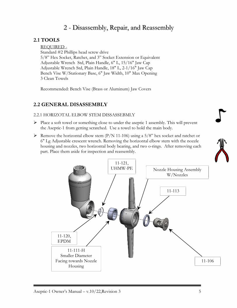
2.2.1 HORIZOTAL ELBOW STEM DISSASSEBMLY
Place a soft towel or something close to under the aseptic 1 assembly. This will prevent the Aseptic-1 from getting scratched. Use a towel to hold the main body.
Remove the horizontal elbow stem (P/N 11-106) using a 5/8” hex socket and ratchet or 6" Lg Adjustable crescent wrench. Removing the horizontal elbow stem with the nozzle housing and nozzles, two horizontal body bearing, and two o-rings. After removing each part. Place them aside for inspection and reassembly.
11-113
11-121, UHMW-PE
11-111-H Smaller Diameter
Facing towards Nozzle Housing
11-106
11-120, EPDM
Nozzle Housing Assembly W/Nozzles
Aseptic-1 Owner’s Manual – v.10/22,Revision 3 6
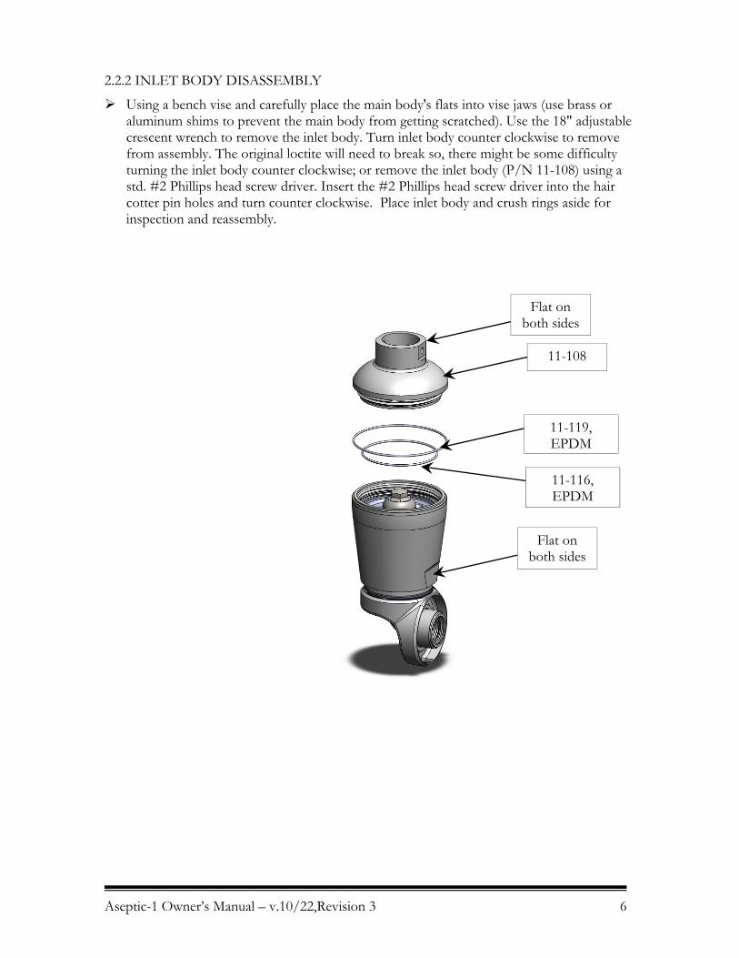
2.2.2 INLET BODY DISASSEMBLY
Using a bench vise and carefully place the main body's flats into vise jaws (use brass or aluminum shims to prevent the main body from getting scratched). Use the 18" adjustable crescent wrench to remove the inlet body. Turn inlet body counter clockwise to remove from assembly. The original loctite will need to break so, there might be some difficulty turning the inlet body counter clockwise; or remove the inlet body (P/N 11-108) using a std. #2 Phillips head screw driver. Insert the #2 Phillips head screw driver into the hair cotter pin holes and turn counter clockwise. Place inlet body and crush rings aside for inspection and reassembly.
11-108
11-119, EPDM
11-116, EPDM
Flat on both sides
Flat on both sides
Aseptic-1 Owner’s Manual – v.10/22,Revision 3 7
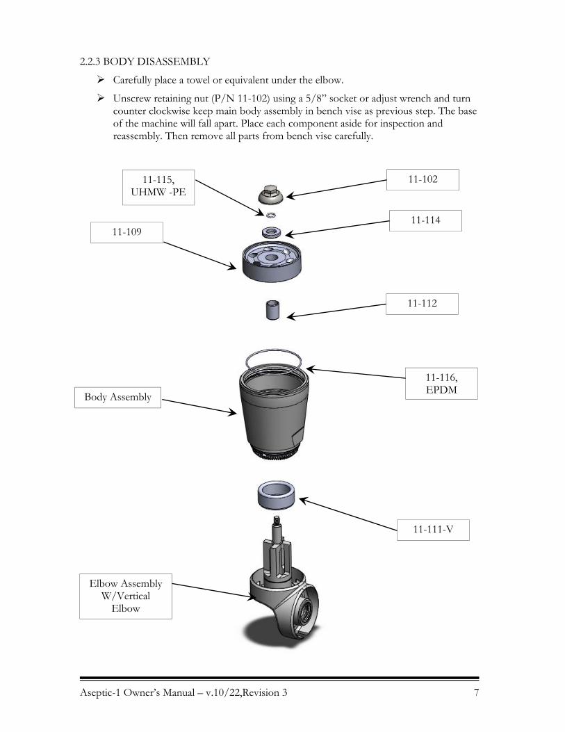
2.2.3 BODY DISASSEMBLY
Carefully place a towel or equivalent under the elbow.
Unscrew retaining nut (P/N 11-102) using a 5/8” socket or adjust wrench and turn counter clockwise keep main body assembly in bench vise as previous step. The base of the machine will fall apart. Place each component aside for inspection and reassembly. Then remove all parts from bench vise carefully.
11-102 11-115, UHMW -PE
11-114 11-109
11-112
11-116, EPDM
11-111-V
Elbow Assembly W/Vertical
Elbow
Body Assembly

Aseptic-1 Owner’s Manual – v.10/22,Revision 3 8
2.2.4 NOZZLE HOUSING DISASSEMBLY
Place nozzle housing assembly in a bench vise. Place bevel gear and front face against jaws (make sure vise jaws are covered this will prevent major scratches and etc).
Unscrew each nozzle with a crescent wrench. Place each nozzle and each o-ring aside for inspection and reassembly.
2.2.4 ELBOW DISASSEMBLY
Place assembly into soft bench vise jaws. Use a flat head screw driver and rotate counter clockwise. Place o-rings and vertical elbow stem aside for inspection.
11-111
11-124, EPDM
11-125, EPDM
NOZZLE HOUSING ASSEMBLY
W/NOZZLES
11-103
11-120 UHMW-PE
11-104
11-121, EPDM
Aseptic-1 Owner’s Manual – v.10/22,Revision 3 9
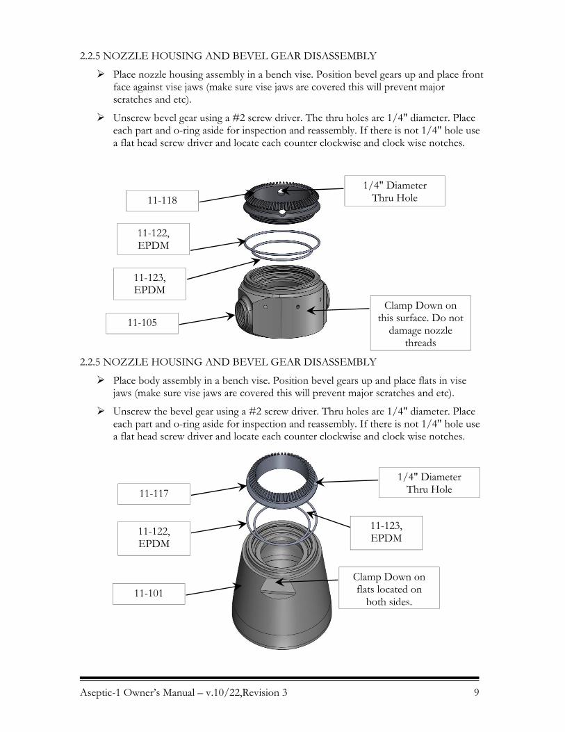
2.2.5 NOZZLE HOUSING AND BEVEL GEAR DISASSEMBLY
Place nozzle housing assembly in a bench vise. Position bevel gears up and place front face against vise jaws (make sure vise jaws are covered this will prevent major scratches and etc).
Unscrew bevel gear using a #2 screw driver. The thru holes are 1/4" diameter. Place each part and o-ring aside for inspection and reassembly. If there is not 1/4" hole use a flat head screw driver and locate each counter clockwise and clock wise notches.
2.2.5 NOZZLE HOUSING AND BEVEL GEAR DISASSEMBLY
Place body assembly in a bench vise. Position bevel gears up and place flats in vise jaws (make sure vise jaws are covered this will prevent major scratches and etc).
Unscrew the bevel gear using a #2 screw driver. Thru holes are 1/4" diameter. Place each part and o-ring aside for inspection and reassembly. If there is not 1/4" hole use a flat head screw driver and locate each counter clockwise and clock wise notches.
Clamp Down on this surface. Do not
damage nozzle threads
1/4" Diameter Thru Hole
Clamp Down on flats located on
both sides.
1/4" Diameter Thru Hole
11-118
11-122, EPDM
11-123, EPDM
11-105
11-117
11-122, EPDM
11-101
11-123, EPDM

Aseptic-1 Owner’s Manual – v.10/22,Revision 3 10
2.3 INSPECTION AND SERVICE OF COMPONENTS & ASSEMBLY
2.3.1 REFERENCE THE 3A SANITARY STANDARDS FOR SPRAY CLEANING DEVICES INTENED TO REMAIN IN PLACE, NUMBER 78-01.
Section D4 states; Cleaning and Inspectability, Spray cleaning devices shall be design so that the product and solution contact surfaces of the spray cleaning devices and all nonremoved appurtenances thereto can be mechanically cleaned and shall be installed to be accessible and readily removable for inspection or readily inspectable in place.
2.3.2 PART INSPECTION
2.3.2.1 Stator
Inspect all the openings on Stator (P/N 11-109) to be sure that they are clear and free of debris.
Holes
Aseptic-1 Owner’s Manual – v.10/22,Revision 3 11
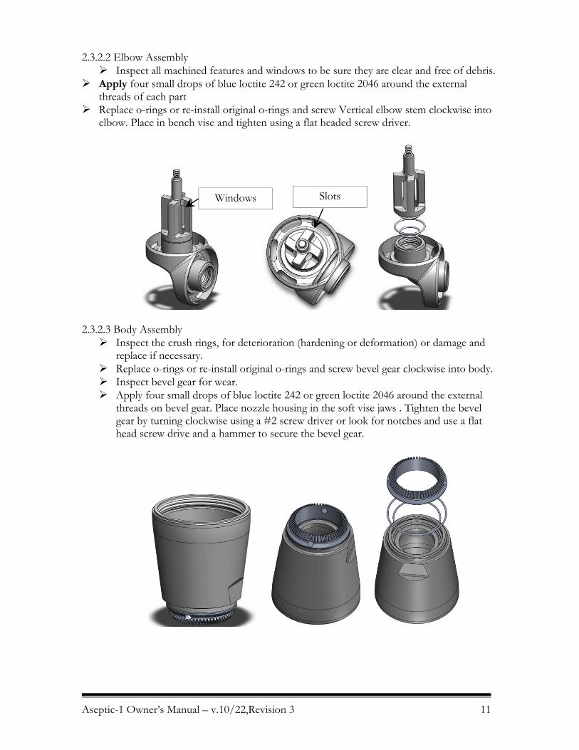
2.3.2.2 Elbow Assembly Inspect all machined features and windows to be sure they are clear and free of debris.
Apply four small drops of blue loctite 242 or green loctite 2046 around the external threads of each part
Replace o-rings or re-install original o-rings and screw Vertical elbow stem clockwise into elbow. Place in bench vise and tighten using a flat headed screw driver.
2.3.2.3 Body Assembly Inspect the crush rings, for deterioration (hardening or deformation) or damage and
replace if necessary. Replace o-rings or re-install original o-rings and screw bevel gear clockwise into body. Inspect bevel gear for wear. Apply four small drops of blue loctite 242 or green loctite 2046 around the external
threads on bevel gear. Place nozzle housing in the soft vise jaws . Tighten the bevel gear by turning clockwise using a #2 screw driver or look for notches and use a flat head screw drive and a hammer to secure the bevel gear.
SlotsWindows
Aseptic-1 Owner’s Manual – v.10/22,Revision 3 12
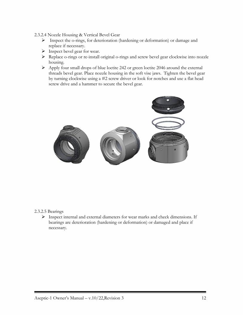
2.3.2.4 Nozzle Housing & Vertical Bevel Gear Inspect the o-rings, for deterioration (hardening or deformation) or damage and
replace if necessary. Inspect bevel gear for wear. Replace o-rings or re-install original o-rings and screw bevel gear clockwise into nozzle
housing. Apply four small drops of blue loctite 242 or green loctite 2046 around the external
threads bevel gear. Place nozzle housing in the soft vise jaws. Tighten the bevel gear by turning clockwise using a #2 screw driver or look for notches and use a flat head screw drive and a hammer to secure the bevel gear.
2.3.2.5 Bearings Inspect internal and external diameters for wear marks and check dimensions. If
bearings are deterioration (hardening or deformation) or damaged and place if necessary.
Aseptic-1 Owner’s Manual – v.10/22,Revision 3 13
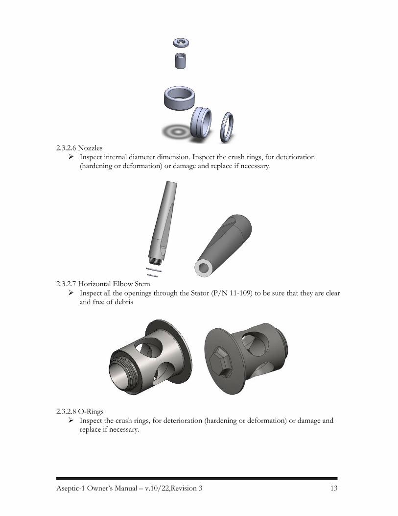
2.3.2.6 Nozzles Inspect internal diameter dimension. Inspect the crush rings, for deterioration
(hardening or deformation) or damage and replace if necessary.
2.3.2.7 Horizontal Elbow Stem Inspect all the openings through the Stator (P/N 11-109) to be sure that they are clear
and free of debris
2.3.2.8 O-Rings Inspect the crush rings, for deterioration (hardening or deformation) or damage and
replace if necessary.
Aseptic-1 Owner’s Manual – v.10/22,Revision 3 14
2.4 REASSEMBLY
2.4.1 GENERAL NOTES
All parts must be cleaned thoroughly before reassembling. Any deposits remaining on the parts can cause difficult disassembly the next time the Gamajet needs servicing.
Apply four small drops of blue loctite 242 or green loctite 2046 around the external threads of each part.
Assemble each o-rings using a cup of water for lubrication. This will allow the each o-ring to be compressed uniformly in each threaded joint assembly.
2.4.2 ELBOW AND BODY ASSEMBLY
Find the elbow assembly and (11-102) Retaining Nut, (11-115) Retaining Nut O-Ring , (11-114) Thrush Bearing, (11-109) Stator, (11-112) Upper Stem Bearing, (11-110) Rotor, (11-116) Stator O-Ring, Body Assembly, (11-111-V) Large Stem Bearing, Elbow Assembly. Place (11-111-V) Large Stem Bearing over the vertical elbow. Place the body assembly onto of the large stem bearing and over the vertical elbow
stem. Slide Upper Stem Bearing (11-112) over the vertical elbow stem shaft. The upper
bearing will rest onto vertical stem windows. Insert the Stator O-Ring in the stator o-ring groove. There is a machined channel at
the bottom of the stator seat. The O-Ring will rest inside the body. Insert the Stator (11-109), with the o-ring groove facing up, into the body. Place
stator over upper stem bearing. Place Thrust Bearing (11-114) onto of the stator. Insert retaining nut o-ring (11-115) onto the vertical elbow. Nearing the small threads.
There is an o-ring groove located at the bottom of the threads. Make sure to snap o-ring into place.
Fasten retaining nut (11-102) onto the vertical elbow stem. Make sure the elbow assembly rotates smoothly. Reference: Page 7.
2.4.3 FASTENING NOZZLES TO NOZZLE HOUSING
Insert the inside nozzle o-ring (11-125) into the nozzle housing with bevel gear. Then insert the outer nozzle o-ring (11-124) into the nozzle housing with bevel gear. Screw in the nozzle; make sure each o-ring stays in place; tighten with a crescent wrench. Repeat previous steps on the second nozzle.
Reference: Page 8.
2.4.4 FASTENING HORIZONTAL ELBOW TO ELBOW ASSEMBLY
Place the horizontal body bearing (11-111-H) onto elbow reference page 5. Insert outside elbow o-ring (11-120) and inside elbow o-ring (11-121) into the elbow
assembly. Place the horizontal elbow stem (11-106) into the horizontal stem bearing. Make sure the
point side of the bearing is face the flange on the horizontal stem. The orientation of the bearing matters.
Aseptic-1 Owner’s Manual – v.10/22,Revision 3 15
Slide the assembled nozzle housing with nozzles onto the horizontal elbow stem. The bevel gear shall face the threads on the elbow stem.
Insert the large body bearing into the nozzle housing assembly. The large body bearing with slip into the bevel gear. Make sure the large body bearing, horizontal elbow stem bearing, and nozzle assembly rotate effortlessly around the horizontal elbow stem. Be vary care assembly the horizontal stem to the elbow. Make sure threads mate together smoothly.
Place the sub assembly down for now. Tighten the horizontal elbow stem with a 5/8” socket or adjustable wrench. Hold the elbow and rotate the nozzle housing assembly nothing should be drawings. Reference: Page 5.
2.4.5 INLET BODY TO BODY ASSEMBLY
Insert another stator o-ring (11-116) locate the stator o-ring groove on top of the stator and insert one upper body o-ring (11-119) onto the body.
Screw the inlet body (11-108) into the body. Fasten down each part using the flats located on the main body and inlet body to tighten down each part.
Spin the gamajet once the assembly is complete. Reference: Page 6.
This completes the reassembly process.

Aseptic-1 Owner’s Manual – v.10/22,Revision 3 16
3 - Preventive Maintenance
Note: A rigorously implemented preventative maintenance program will significantly reduce repair costs over the life of the Gamajet. The foundation of such a program is regularly scheduled inspections to discover and replace worn or damaged parts before they can cause the failure of other, more costly, components. The inspection intervals required will depend on the severity of the application, but 100 hours of operation is recommended initially.
Note: Part numbers appearing below may be used to identify parts in the exploded views in Appendix B.
3.1 STORAGE The Gamajet should be washed out with clean water after each use to remove any foreign material or soft substances left in the machine that may harden during storage and cause the Gamajet to seize or lock up. A clean water rinse through the Gamajet will also wash out any residues of chemical cleaners or recirculated wash water that could adversely affect the seals and O-rings during prolonged contact in storage. The best position to store the Gamajet is to stand it up with the inlet connection facing down.
3.2 EXTERNAL INSPECTION INTERVALS Before every shift, the Stator and the Nozzles should be inspected for debris. Examine the Stator by loosening the inlet body. Look into each Nozzle for signs of debris or build-up. Also, the vent holes on either side of the nozzle housing should be checked for blockage. Use a fine wire or compressed air to clear them, if necessary.
3.3 INTERNAL INSPECTION INTERVALS An interval of 100 hours is recommended initially. If all of the components are found to be in acceptable condition after the first 100 hours, the Gamajet may then be inspected and routine preventive maintenance should be performed every 300 to 500 hours of operation, depending on the severity of use.
3.4 TIPS All the Bearings, Bushings, Seals and O-rings are wear parts. Ideally, they should all be replaced, as a group, every 300 to 500 hours of operation, depending on the severity of use. If just one Bearing or Seal is worn or damaged, replace both it and its mate, not just the worn or damaged part.
Aseptic-1 Owner’s Manual – v.10/22,Revision 3 17
4 - Troubleshooting Guide
Note: Part numbers appearing below may be used to identify parts in the exploded views in previous sections and Appendix B.
4.1 MACHINE DOES NOT ROTATE
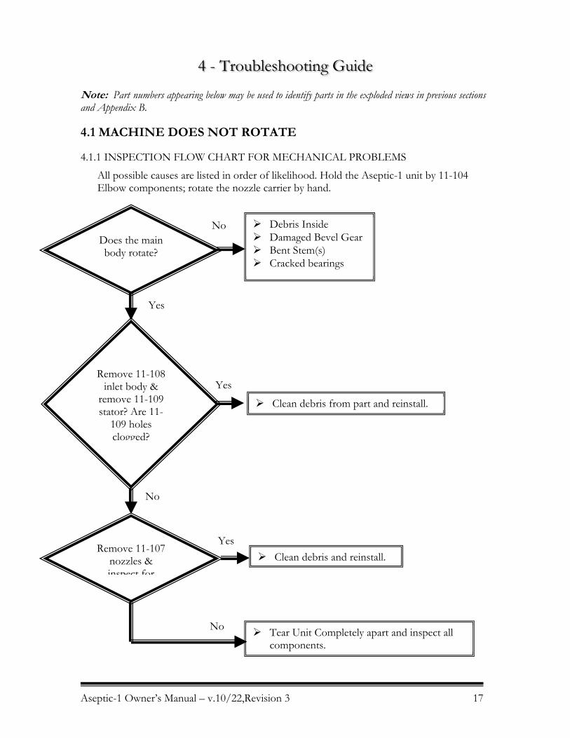
4.1.1 INSPECTION FLOW CHART FOR MECHANICAL PROBLEMS
All possible causes are listed in order of likelihood. Hold the Aseptic-1 unit by 11-104 Elbow components; rotate the nozzle carrier by hand.
Does the main body rotate?
Debris Inside Damaged Bevel Gear Bent Stem(s) Cracked bearings
Remove 11-108 inlet body &
remove 11-109 stator? Are 11-
109 holes clogged?
Clean debris from part and reinstall.
Remove 11-107 nozzles & inspect for
Clean debris and reinstall.
Tear Unit Completely apart and inspect all components.
No
Yes
Yes
No
Yes
No
Aseptic-1 Owner’s Manual – v.10/22,Revision 3 18
4.1.2 INSUFFICIENT FLOW
The Gamajet was configured to meet certain operating conditions supplied to us, such as flow rate (GPM), pressure (PSI), temperature, chemical content of the wash fluid, cycle time, etc. If the Nozzle size is too small and/or the opening at the bottom of the Stator is too large, the Tee Housing will not turn.
Look for restrictions in the fluid supply such as a clogged filter, kinked hose, or deposits in the piping.
4.1.3 TIGHT CLEARANCES
A newly overhauled Aseptic-1 should to operate when first returned to service. If the machine seems otherwise fine, try running it with at least one Nozzle Tip removed. The reduction in pressure and additional flow will invariably be enough to overcome the extra resistance of new Bearings. A few minutes of operation should loosen the clearances enough for the machine to run normally with the Nozzles remounted. The nozzle carrier may only need to be rotated several times
4.1.4 DEBRIS INSIDE
Loosen the remove the inlet body, and then look at the Stator. Look for and remove any debris caught in the passageways of Stator. Remove any material wound around the Rotor Shaft. You may need to remove the retaining nut if debris is adhered to the rotor. In addition check for any debris caught in the outlet holes of the Stems, the vent holes, the nose of the elbow, the Nozzle Housing, and the Nozzles.
4.2 CLEANING SOLUTION LEAKAGE
4.2.1 WORN BEARINGS & SEALS
Water exiting from the CIP holes and the self rinse holes of the nozzle carrier will cause a significant spray to exit around the body and elbow. However, excessive leakage from the elbow or Nozzle Housing usually indicates the machine is fine. Inspect them for wear marks on each bearing. If excessive wearing as occurred replace the bearing.
4.2.5 WORN ELBOW STEMS
If the horizontal and vertical elbow stem have sever worn marks. Replace them if metal surfaces are scored or grooved.
4.3 POOR CLEANING PERFORMANCE
4.3.1 INADEQUATE FLOW AND PRESSURE
Check the pressure at the Gamajet inlet under actual operating conditions. The supply piping and hoses must be large enough to handle the flow rate required for the nozzle size being used to ensure adequate pressure.
Insufficient pressure may also result from line losses when the machine is far from the pump, so the line size must be increased accordingly for long runs. Although the Gamajet will rotate at low flow rates, effective cleaning may require considerably more flow.
Aseptic-1 Owner’s Manual – v.10/22,Revision 3 19
Proper mechanical operation (the unit turns) is NOT the same thing as effective cleaning (the soils have been removed)!
4.3.2 CHEMICAL CONCENTRATION AND TEMPERATURE
Verify that the cleaning solution is the correct compound and in the concentration needed for the deposit being cleaned. If heating is necessary, also check that the solution is at the proper temperature.
4.3.3 PLUGGED NOZZLES
Unscrew the Nozzles and inspect for any debris.
4.3.4 SLOW OR NO ROTATION OF THE HOUSINGS
This will result in partial or erratic washing coverage. Refer to previous sections for more information.
4.3.5 GAMAJET CONFIGURATION
Determine if the deposit being cleaned requires greater jet impact or longer jet dwell time (slower rotation) for more thorough scrubbing. Confirm that the Gamajet nozzle size, turbine, and gearing are correct for the specific application. Contact Gamajet for assistance, if needed.
4.3.6 INADEQUATE DRAINAGE
Ensure that the vessel drains the effluent or used wash fluid as fast as it’s being sprayed in through the Gamajet. The floor of the vessel should be sloped or pitched toward the drain and the drainage opening should be large enough to gravity-drain the effluent from the vessel. If you still have puddling (build-up of the wash fluid so it covers the floor and shields the residues underneath), use some form of pump to suck out the effluent.
4.4 OWNER’S MANUAL UPDATES Please visit our web site, www.gamajet.com, for information on receiving updates to this manual.

Aseptic-1 Owner’s Manual – v.9/02 C-1
Appendix A –Spare Part List
GAMAJET ASEPTIC 1 SPARE PART LIST
KIT #11-3A-KIT
Aseptic-1 Spare Parts Kit
Part No. Quantity Description
11-111-H 1 Large Horizontal Stem Bearing
11-111-V 1 Large Vertical Stem Bearing
11-112 1 Upper Stem Bearing
11-113 1 Horizontal Stem Bearing
11-114 1 Thrust Bearing
11-115 1 Retaining Nut O'Ring (UHMW-PE)
11-116 2 Stator O'Ring (EPDM)
11-119 1 Upper Body O'Ring (EPDM)
11-120 2 Outside Elbow O’Ring (UHMW-PE)
11-121 2 Inside Elbow O'Ring (EPDM)
11-122 2 Outside Bevel Gear O'Ring (EPDM)
11-123 2 Inside Bevel Gear O'Ring (EPDM)
11-124 2 Outer Nozzle O'Ring (EPDM)
11-125 2 Inner Nozzle O'Ring (EPDM)
Aseptic-1 Owner’s Manual – v.9/02 C-2
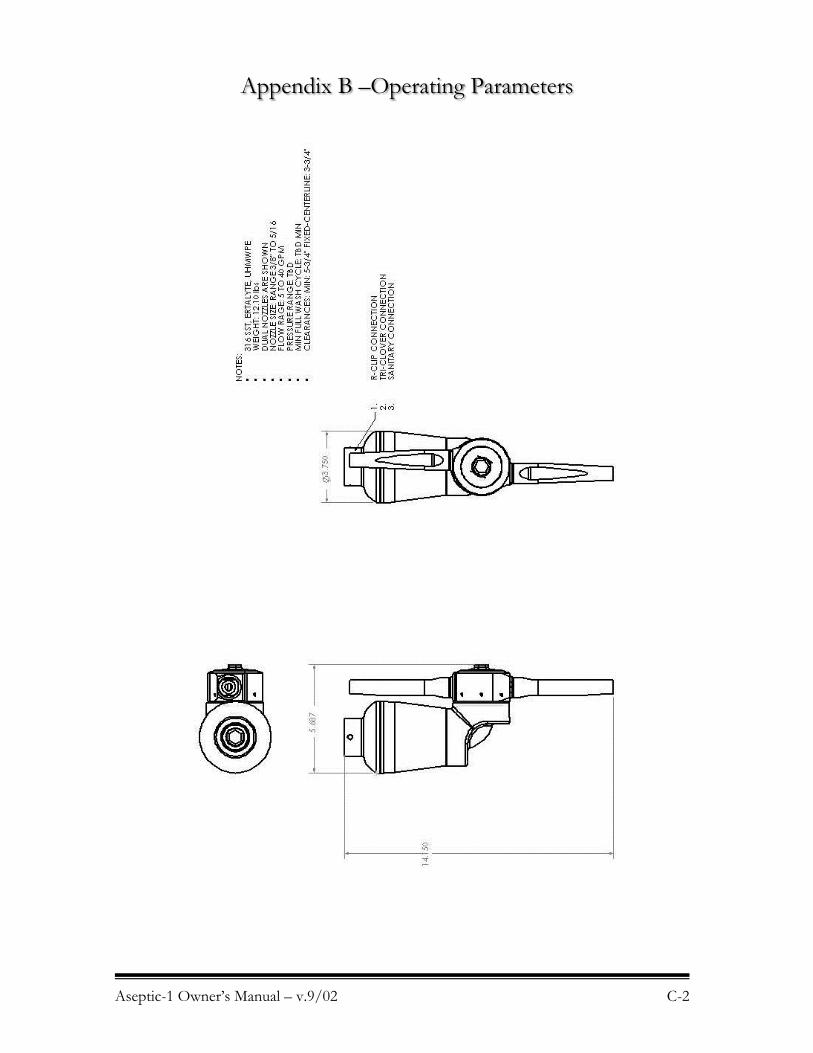
Appendix B –Operating Parameters

Aseptic-1 Owner’s Manual – v.9/02 C-3
Appendix C –Performance Curves
Under construction