garage door operator carteck drive 500 carteck drive 600 · dear customer, congratulations on your...
TRANSCRIPT

CarTeck_46900V202_472017_0-DRE_Rev-D_EN
Platz für Garantieaufkleber
EN TRANSLATION OF THE ORIGINAL INSTALLATION AND OPERATING MANUAL
Garage door operator
CarTeck DRIVE 500CarTeck DRIVE 600
EN TRANSLATION OF THE ORIGINAL INSTALLATION AND OPERATING MANUAL
01926 463 888 www.garagedoorsonline.co.uk 06/2019
01926 463 888 www.garagedoorsonline.co.uk 06/2019

Dear customer,
Congratulations on your purchase of a product of SOMMER Antriebs- und Funktechnik GmbH.This product has been developed and manufactured under high standards of quality and with reference to ISO 9001. Our passion for the product is just as important to us as the needs and requirements of our customers. We place particular emphasis on the safety and reliability of our products.Read this installation and operating manual carefully and follow all instructions. This will ensure that you can install and operate the product safely and optimally.If you have any questions, please contact your specialist retailer, installer or contact.
Information on the operator:Serial No.: See the title page of the installation and operating manual (if applicable warranty label).
Year of manufacture: from 03/2015Information on the installation and operating manualVersion of the installation and operating manual: CarTeck_46900V202_472017_0-DRE_Rev-D_EN
WarrantyThe warranty complies with statutory requirements. The contact person for warranties is the qualified dealer. The warranty is only valid in the country in which the operator was purchased. There is no warranty for consumables such as batteries, accumulators and safety products as well as bulbs. This also applies for wear parts. The operator is only designed for a limited frequency of use. More frequent use leads to increased wear.
Contact dataIf you require after-sales service, spare parts or accessories, please contact your qualified specialist retailer or installer.
Feedback on this installation and operating manualWe have tried to make the Installation and Operating Manual as easy as possible to follow. If you have any suggestions as to how we could improve it or if you think more information is needed, please send your suggestions to us:
+49 (0) 7021 8001-403
ServiceIf you require service, please contact us on our service hotline (fee required) or see our web site:
+49 (0) 900 1800-150(0.14 euros/minute from land line telephones in Germany, mobile prices may vary)
www.sommer.eu/de/kundendienst.html
Copyright and proprietary rightsThe manufacturer retains the copyright for this Installation and Operating Manual. No part of this installation and operating manual may be reproduced in any form without the written permission of SOMMER Antriebs- und Funktechnik GmbH or processed, copied, or distributed using electronic systems. Violations of the above stipulations will lead to damage claims. All brands mentioned in these instructions are the property of their respective manufacturer and hereby recognized as such.
01926 463 888 www.garagedoorsonline.co.uk 06/2019
01926 463 888 www.garagedoorsonline.co.uk 06/2019
3
Table of contents
10. Connections and special functions of the motor carriage 40
10.1 Motor carriage circuit board 4010.2 Connection options on the motor carriage 4110.3 Reducing illumination power of LEDs 4210.4 Explanation of the radio channels 4210.5 Programming the transmitter 4210.6 Information on Memo 4210.7 Cancelling programming mode 4310.8 Deleting a transmitter button from the radio
channel 4310.9 Deleting transmitter completely from
the receiver 4310.10 Deleting radio channel in the receiver 4310.11 Deleting all radio channels in the receiver 4310.12 Programming a second transmitter by radio
(HFL) 4410.13 Resetting the control unit 4410.14 Setting the DIP switches on the motor carriage 4510.15 Setting automatic closing function - defining
basic values 4510.16 Setting the lighting function 4610.17 Setting partial opening 4610.18 Deleting partial opening 4710.19 Wicket door safety device 4710.20 12 V output 4710.21 SOMlink 48
11. Connections and special functions of the ceiling control unit 49
11.1 Ceiling control unit circuit board 4911.2 Connection options of the ceiling control unit 5011.3 Setting the DIP switches on the ceiling
control unit 5211.4 Button 2 for partial opening 5211.5 Deleting partial opening 5311.6 Photocell and frame photocell 5311.7 Wall station 5411.8 Conex 5511.9 Output OC 5511.10 Relay 5611.11 Installing and removing the accumulator 56
12. twin operation 5812.1 twin operation 5812.2 Installing the operators 5812.3 Selecting and configuring master and slave 5812.4 Partial opening 5912.5 Defined opening and closing 5912.6 Door status display 5912.7 Lighting for twin operation 5912.8 Photocell 5912.9 External button 5912.10 Reset 59
1. About this installation and operating manual 51.1 Storage and circulation of the installation and
operating manual 51.2 Important for translations 51.3 Description of the product type 51.4 Target groups of the installation and operating
manual 51.5 Explanation of warning symbols and notes 51.6 Special warnings, hazard symbols and
mandatory signs 61.7 Information regarding the depiction of text 81.8 Intended use of the operator 81.9 Improper use of the operator 91.10 Qualifications of personnel 91.11 For the user 10
2. General safety instructions 112.1 Basic safety instructions for operation 112.2 Additional safety information for the radio
remote control 13
3. Description of function and product 143.1 The operator and its mode of operation 143.2 Safety equipment 143.3 Product designation 153.4 Explanation of tool symbols 153.5 Scope of delivery 163.6 Dimensions 173.7 Technical data 173.8 Door types and accessories 18
4. Tools and protective equipment 194.1 Required tools and personal protective
equipment 19
5. Declaration of Installation 20
6. Installation 216.1 Important information on installation 216.2 Preparation for installation 236.3 Installation of the operator system 246.4 Installation on the door 26
7. Removing and fastening covers 327.1 Cover of the motor carriage 327.2 Cover of the ceiling control unit 33
8. Electrical connection 348.1 Connection to a power socket 34
9. Commissioning 359.1 Safety information for commissioning 359.2 Initial operation 369.3 Detecting obstacles during the force
programming run 389.4 Mechanical adjustment of the end positions 389.5 Attaching information sign and warning signs 39
01926 463 888 www.garagedoorsonline.co.uk 06/2019
01926 463 888 www.garagedoorsonline.co.uk 06/2019

4
13. Function test and final test 6013.1 Testing obstacle detection 6013.2 Handover of door system 61
14. Operation 6214.1 Safety information on operation 6214.2 Handover to the user 6314.3 Operating modes of door movement 6414.4 Obstacle detection 6514.5 Power-saving mode 6514.6 Operation during power failure 6514.7 Function of the emergency release 65
15. Maintenance and care 6715.1 Safety instructions for maintenance and care 6715.2 Maintenance schedule 6815.3 Care 69
16. Troubleshooting 7016.1 Safety instructions for troubleshooting 7016.2 Troubleshooting 7116.3 Time sequences of operator lighting in normal
mode and in case of faults 7216.4 Troubleshooting table 7316.5 Replacing the motor carriage 74
17. Taking out of operation, storage and disposal 7517.1 Taking the operator out of operation and
disassembly 7517.2 Storage 7617.3 Disposal of waste 76
18. Short instructions for installation 77
19. Connection diagrams and functions of the DIP switches 80
01926 463 888 www.garagedoorsonline.co.uk 06/2019
01926 463 888 www.garagedoorsonline.co.uk 06/2019
5
1. About this installation and operating manual
1.1 Storage and circulation of the installation and operating manual
Read this installation and operating manual carefully and completely before installation, commissioning and operation and also before removal. Follow all warnings and safety instructions.Keep this installation and operating manual accessible to all users at all times at the place of use.A replacement for the installation and operating manual can be downloaded from SOMMER at:www.sommer.euDuring the transfer or resale of the operator to third parties, the following documents must be passed on to the new owner:
• EC Declaration of Conformity• handover protocol and inspection book• this installation and operating manual• proof of regular maintenance, testing and care• documents recording retrofitting and repairs
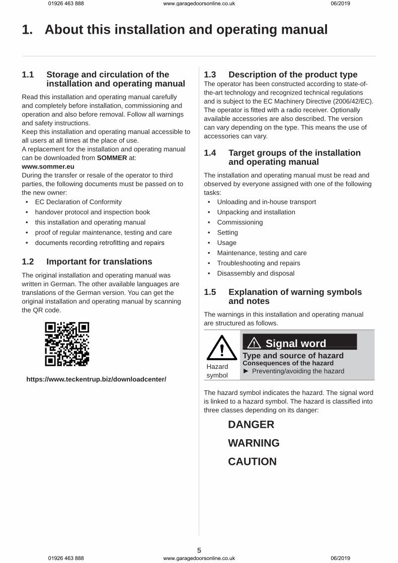
1.2 Important for translationsThe original installation and operating manual was written in German. The other available languages are translations of the German version. You can get the original installation and operating manual by scanning the QR code.
https://www.teckentrup.biz/downloadcenter/
1.3 Description of the product typeThe operator has been constructed according to state-of-the-art technology and recognized technical regulations and is subject to the EC Machinery Directive (2006/42/EC).The operator is fitted with a radio receiver. Optionally available accessories are also described. The version can vary depending on the type. This means the use of accessories can vary.
1.4 Target groups of the installation and operating manual
The installation and operating manual must be read and observed by everyone assigned with one of the following tasks:
• Unloading and in-house transport• Unpacking and installation• Commissioning• Setting• Usage• Maintenance, testing and care• Troubleshooting and repairs• Disassembly and disposal
1.5 Explanation of warning symbols and notes
The warnings in this installation and operating manual are structured as follows.
Hazard symbol
Signal wordType and source of hazardConsequences of the hazard
► Preventing/avoiding the hazard
The hazard symbol indicates the hazard. The signal word is linked to a hazard symbol. The hazard is classified into three classes depending on its danger:
DANGER WARNING CAUTION
01926 463 888 www.garagedoorsonline.co.uk 06/2019
01926 463 888 www.garagedoorsonline.co.uk 06/2019
6
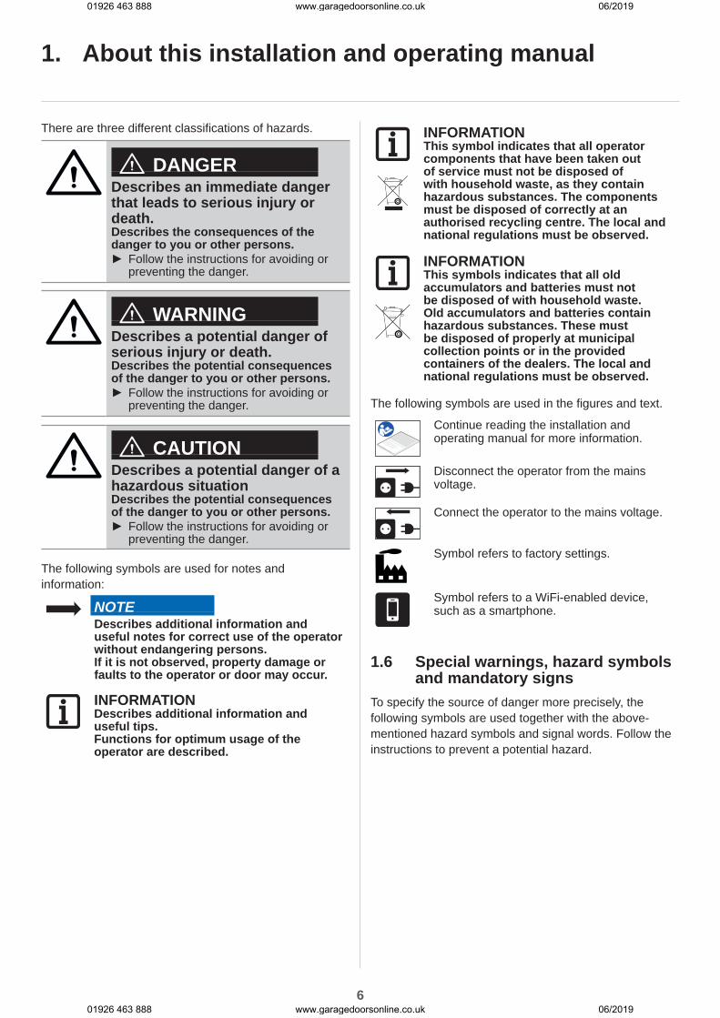
There are three different classifications of hazards.
DANGERDescribes an immediate danger that leads to serious injury or death.Describes the consequences of the danger to you or other persons.
► Follow the instructions for avoiding or preventing the danger.
WARNINGDescribes a potential danger of serious injury or death.Describes the potential consequences of the danger to you or other persons.
► Follow the instructions for avoiding or preventing the danger.
CAUTIONDescribes a potential danger of a hazardous situationDescribes the potential consequences of the danger to you or other persons.
► Follow the instructions for avoiding or preventing the danger.
The following symbols are used for notes and information:
NOTEDescribes additional information and useful notes for correct use of the operator without endangering persons.If it is not observed, property damage or faults to the operator or door may occur.
INFORMATIONDescribes additional information and useful tips.Functions for optimum usage of the operator are described.
INFORMATIONThis symbol indicates that all operator components that have been taken out of service must not be disposed of with household waste, as they contain hazardous substances. The components must be disposed of correctly at an authorised recycling centre. The local and national regulations must be observed.
INFORMATIONThis symbols indicates that all old accumulators and batteries must not be disposed of with household waste. Old accumulators and batteries contain hazardous substances. These must be disposed of properly at municipal collection points or in the provided containers of the dealers. The local and national regulations must be observed.
The following symbols are used in the figures and text.
Continue reading the installation and operating manual for more information.
Disconnect the operator from the mains voltage.
Connect the operator to the mains voltage.
Symbol refers to factory settings.
Symbol refers to a WiFi-enabled device, such as a smartphone.
1.6 Special warnings, hazard symbols and mandatory signs
To specify the source of danger more precisely, the following symbols are used together with the above-mentioned hazard symbols and signal words. Follow the instructions to prevent a potential hazard.
1. About this installation and operating manual
01926 463 888 www.garagedoorsonline.co.uk 06/2019
01926 463 888 www.garagedoorsonline.co.uk 06/2019
7
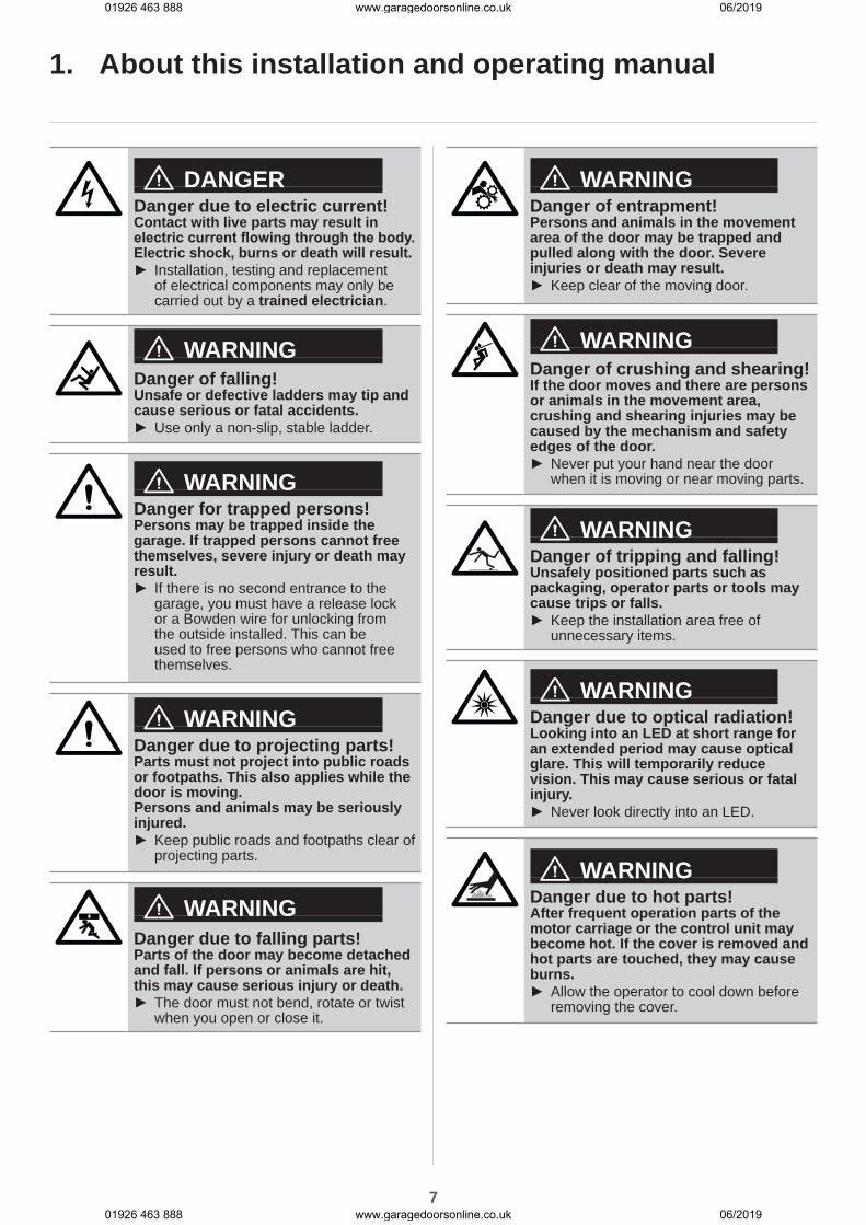
DANGERDanger due to electric current!Contact with live parts may result in electric current flowing through the body. Electric shock, burns or death will result.
► Installation, testing and replacement of electrical components may only be carried out by a trained electrician.
WARNINGDanger of falling!Unsafe or defective ladders may tip and cause serious or fatal accidents.
► Use only a non-slip, stable ladder.
WARNINGDanger for trapped persons!Persons may be trapped inside the garage. If trapped persons cannot free themselves, severe injury or death may result.
► If there is no second entrance to the garage, you must have a release lock or a Bowden wire for unlocking from the outside installed. This can be used to free persons who cannot free themselves.
WARNINGDanger due to projecting parts!Parts must not project into public roads or footpaths. This also applies while the door is moving.Persons and animals may be seriously injured.
► Keep public roads and footpaths clear of projecting parts.
WARNINGDanger due to falling parts!Parts of the door may become detached and fall. If persons or animals are hit, this may cause serious injury or death.
► The door must not bend, rotate or twist when you open or close it.
WARNINGDanger of entrapment!Persons and animals in the movement area of the door may be trapped and pulled along with the door. Severe injuries or death may result.
► Keep clear of the moving door.
WARNINGDanger of crushing and shearing!If the door moves and there are persons or animals in the movement area, crushing and shearing injuries may be caused by the mechanism and safety edges of the door.
► Never put your hand near the door when it is moving or near moving parts.
WARNINGDanger of tripping and falling!Unsafely positioned parts such as packaging, operator parts or tools may cause trips or falls.
► Keep the installation area free of unnecessary items.
WARNINGDanger due to optical radiation!Looking into an LED at short range for an extended period may cause optical glare. This will temporarily reduce vision. This may cause serious or fatal injury.
► Never look directly into an LED.
WARNINGDanger due to hot parts!After frequent operation parts of the motor carriage or the control unit may become hot. If the cover is removed and hot parts are touched, they may cause burns.
► Allow the operator to cool down before removing the cover.
1. About this installation and operating manual
01926 463 888 www.garagedoorsonline.co.uk 06/2019
01926 463 888 www.garagedoorsonline.co.uk 06/2019
8
1. About this installation and operating manual
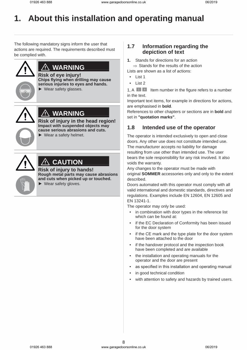
The following mandatory signs inform the user that actions are required. The requirements described must be complied with.
WARNINGRisk of eye injury!Chips flying when drilling may cause serious injuries to eyes and hands.
► Wear safety glasses.
WARNINGRisk of injury in the head region!Impact with suspended objects may cause serious abrasions and cuts.
► Wear a safety helmet.
CAUTIONRisk of injury to hands!Rough metal parts may cause abrasions and cuts when picked up or touched.
► Wear safety gloves.
1.7 Information regarding the depiction of text
1. Stands for directions for an action ⇒ Stands for the results of the action
Lists are shown as a list of actions:• List 1• List 2
1, A 1 A Item number in the figure refers to a number in the text.Important text items, for example in directions for actions, are emphasised in bold.References to other chapters or sections are in bold and set in "quotation marks".
1.8 Intended use of the operatorThe operator is intended exclusively to open and close doors. Any other use does not constitute intended use. The manufacturer accepts no liability for damage resulting from use other than intended use. The user bears the sole responsibility for any risk involved. It also voids the warranty.Any changes to the operator must be made with original SOMMER accessories only and only to the extent described.Doors automated with this operator must comply with all valid international and domestic standards, directives and regulations. Examples include EN 12604, EN 12605 and EN 13241-1.The operator may only be used:
• in combination with door types in the reference list which can be found at:
• if the EC Declaration of Conformity has been issued for the door system
• if the CE mark and the type plate for the door system have been attached to the door
• if the handover protocol and the inspection book have been completed and are available
• the installation and operating manuals for the operator and the door are present
• as specified in this installation and operating manual• in good technical condition• with attention to safety and hazards by trained users.
01926 463 888 www.garagedoorsonline.co.uk 06/2019
01926 463 888 www.garagedoorsonline.co.uk 06/2019

9
1.9 Improper use of the operatorAny other use or additional use that has not been described in Chapter 1.8 constitutes improper use. The user bears the sole responsibility for any risk involved.The manufacturer's warranty will be voided by:
• damage caused by other use and improper use• use with defective parts• unauthorised modifications to the operator• modifications and non-approved programming of the
operator and its componentsThe door must not be part of a fire protection system, an evacuation path or an emergency exit that automatically closes the door in the event of fire. Installation of the operator will prevent automatic closing.Observe the local building regulations.The operator may not be used in:
• areas with explosion hazard• very salty air• aggressive atmosphere, including chlorine
1.10 Qualifications of personnelPeople under the influence of drugs, alcohol, or medications that can influence their ability to react may not work on the operator.After installation of the operator, the person responsible for the installation of the operator must complete an EC Declaration of Conformity for the door system in accordance with Machinery Directive 2006/42/EC and apply the CE mark and a type plate to the door system. This also applies if the operator is retrofitted to a manually operated door. In addition, a handover protocol and an inspection book must be completed.The following is available:
• EC Declaration of Conformity• handover protocol for the operator
http://som4.me/konform
Trained qualified specialist for installation, commissioning and disassemblyThis installation and operating manual must be read, understood and complied with by a qualified specialist who installs or performs maintenance on the operator.Work on the electrical system and live parts may be performed only by a trained electrician in accordance with EN 50110-1.The installation, commissioning and disassembly of the operator may only be performed by a qualified specialist.The qualified specialist must be familiar with the following standards:
• EN 13241-1 Doors and gates - Product standard
• EN 12604 Doors and gates - Mechanical aspects - Requirements
• EN 12605 Doors and gates - Mechanical aspects - Test methods
• EN 12445 and EN 12453 - Safety in use of power-operated doors
A qualified specialist is a person ordered by the installer. The qualified specialist must instruct the user:
• on the operation of the operator and its dangers• on the handling of the manual emergency release• on regular maintenance, testing and care which the
user can carry out
The user must be informed that other users must be instructed on the operation of the operator, its dangers as well as the emergency release.The user must be informed about which work must only be performed by a qualified specialist:
• installation of accessories• settings• regular maintenance, testing and care• troubleshooting and repairs
The following documents for the door system must be handed over to the user:
• EC Declaration of Conformity• handover protocol and inspection book• the installation and operating manuals for the
operator and the door
1. About this installation and operating manual
01926 463 888 www.garagedoorsonline.co.uk 06/2019
01926 463 888 www.garagedoorsonline.co.uk 06/2019

10
1. About this installation and operating manual
1.11 For the userThe user must ensure that the CE mark and the type plate have been attached to the door system.The following documents for the door system must be handed over to the user:
• the installation and operating manuals for the operator and the door
• inspection book• EC Declaration of Conformity• handover protocol
The user must always keep this installation and operating manual at the place of use, ready for consultation and accessible to all users.The user is responsible for:
• the intended use of the operator• its good condition• instructing all users how to use the door system and
in the associated hazards• operation• maintenance, inspection and care by a qualified
specialist• troubleshooting and repair by a qualified specialist
The operator must not be used by persons with restricted physical, sensory or mental capacity or who lack experience and knowledge. All users must be specially instructed and have read and understood the installation and operating manual.Children must never play with or use the operator, even under supervision. Children must be kept clear of the operator. Handheld transmitters or other control devices must never be given to children. Handheld transmitters must be safely stored and protected against unintended and unauthorised use.The user will observe the accident prevention regulations and the applicable standards in Germany. In other countries, the user must comply with the applicable national regulations.The guideline "Technical regulations for workplaces ASR A1.7" of the German committee for workplaces (ASTA) is applicable for commercial use. The guidelines described must be observed and complied with. This applies for the use in Germany. In other countries the user must comply with the applicable national regulations.
01926 463 888 www.garagedoorsonline.co.uk 06/2019
01926 463 888 www.garagedoorsonline.co.uk 06/2019
11
2. General safety instructions
2.1 Basic safety instructions for operation
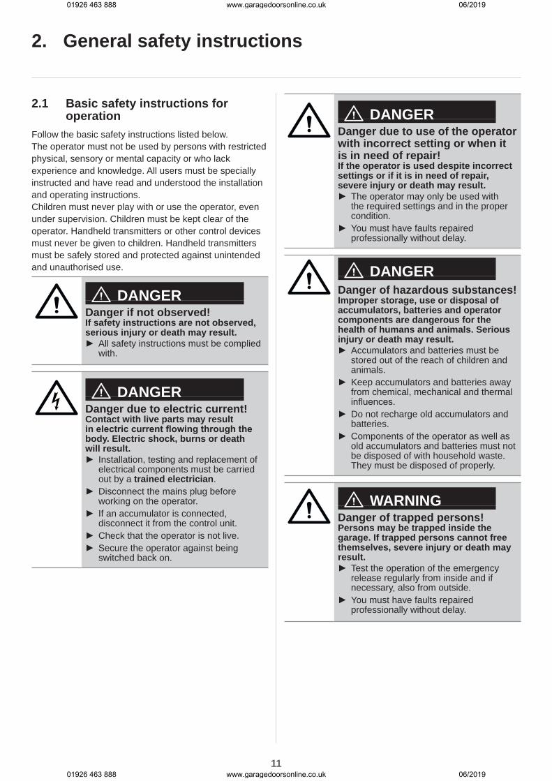
Follow the basic safety instructions listed below.The operator must not be used by persons with restricted physical, sensory or mental capacity or who lack experience and knowledge. All users must be specially instructed and have read and understood the installation and operating instructions.Children must never play with or use the operator, even under supervision. Children must be kept clear of the operator. Handheld transmitters or other control devices must never be given to children. Handheld transmitters must be safely stored and protected against unintended and unauthorised use.
DANGERDanger if not observed!If safety instructions are not observed, serious injury or death may result.
► All safety instructions must be complied with.
DANGERDanger due to electric current!Contact with live parts may result in electric current flowing through the body. Electric shock, burns or death will result.
► Installation, testing and replacement of electrical components must be carried out by a trained electrician.
► Disconnect the mains plug before working on the operator.
► If an accumulator is connected, disconnect it from the control unit.
► Check that the operator is not live. ► Secure the operator against being switched back on.
DANGERDanger due to use of the operator with incorrect setting or when it is in need of repair!If the operator is used despite incorrect settings or if it is in need of repair, severe injury or death may result.
► The operator may only be used with the required settings and in the proper condition.
► You must have faults repaired professionally without delay.
DANGERDanger of hazardous substances!Improper storage, use or disposal of accumulators, batteries and operator components are dangerous for the health of humans and animals. Serious injury or death may result.
► Accumulators and batteries must be stored out of the reach of children and animals.
► Keep accumulators and batteries away from chemical, mechanical and thermal influences.
► Do not recharge old accumulators and batteries.
► Components of the operator as well as old accumulators and batteries must not be disposed of with household waste. They must be disposed of properly.
WARNINGDanger of trapped persons!Persons may be trapped inside the garage. If trapped persons cannot free themselves, severe injury or death may result.
► Test the operation of the emergency release regularly from inside and if necessary, also from outside.
► You must have faults repaired professionally without delay.
01926 463 888 www.garagedoorsonline.co.uk 06/2019
01926 463 888 www.garagedoorsonline.co.uk 06/2019

12
WARNINGDanger due to projecting parts!Gate leaves or other parts must not project into public roads or footpaths. This also applies while the door is moving.This may cause serious injury or death to persons or animals.
► Keep public roads and footpaths clear of projecting parts.
WARNINGDanger due to falling parts of doors!Actuating the emergency release can lead to uncontrolled door movement if
• springs are weakened or broken.• the door has not been optimally
weight-balanced.Falling parts may cause a hazard. Severe injuries or death may result.
► Check the weight balance of the door at regular intervals.
► Pay attention to the movement of the door when the emergency release is actuated.
► Keep clear of the movement area of the door.
WARNINGDanger of entrapment!Persons and animals in the movement area of the door may be trapped and pulled along with the door. Severe injuries or death may result.
► Keep clear of the movement area of the door.
WARNINGDanger of crushing and shearing!If the door moves and there are persons or animals in the movement area, crushing and shearing injuries may be caused by the mechanism and safety edges of the door.
► Only use the operator when you have a direct view of the door.
► All danger zones must be visible during the entire door operation.
► Always keep the moving door in sight. ► Keep persons and animals clear of the range of movement of the door.
► Never put your hand near the door when it is moving or near moving parts. In particular, do not reach into the moving push arm.
► Do not reach into the ceiling suspension unit when the motor carriage is running along the track.
► Do not drive through the door until it has opened completely.
► Store the handheld transmitter so that unauthorised or accidental operation, e.g., by children or animals, is impossible.
► Never stand under the opened door.
WARNINGDanger due to optical radiation!Looking into an LED at short range for an extended period may cause optical glare. This may temporarily reduce vision. This may cause serious or fatal accidents.
► Never look directly into an LED.
NOTEDispose of all components in accordance with local or national regulations to avoid environmental damage.
2. General safety instructions
01926 463 888 www.garagedoorsonline.co.uk 06/2019
01926 463 888 www.garagedoorsonline.co.uk 06/2019
13
2. General safety instructions
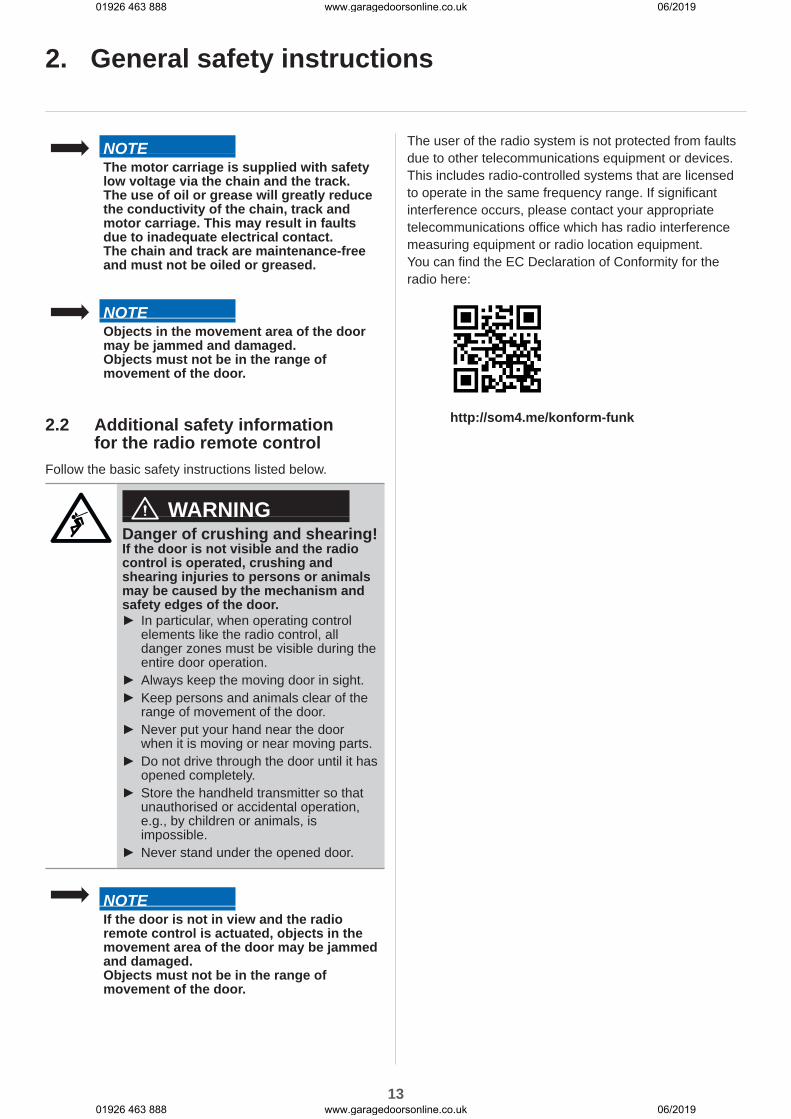
NOTEThe motor carriage is supplied with safety low voltage via the chain and the track.The use of oil or grease will greatly reduce the conductivity of the chain, track and motor carriage. This may result in faults due to inadequate electrical contact.The chain and track are maintenance-free and must not be oiled or greased.
NOTEObjects in the movement area of the door may be jammed and damaged.Objects must not be in the range of movement of the door.
2.2 Additional safety information for the radio remote control
Follow the basic safety instructions listed below.
WARNINGDanger of crushing and shearing!If the door is not visible and the radio control is operated, crushing and shearing injuries to persons or animals may be caused by the mechanism and safety edges of the door.
► In particular, when operating control elements like the radio control, all danger zones must be visible during the entire door operation.
► Always keep the moving door in sight. ► Keep persons and animals clear of the range of movement of the door.
► Never put your hand near the door when it is moving or near moving parts.
► Do not drive through the door until it has opened completely.
► Store the handheld transmitter so that unauthorised or accidental operation, e.g., by children or animals, is impossible.
► Never stand under the opened door.
NOTEIf the door is not in view and the radio remote control is actuated, objects in the movement area of the door may be jammed and damaged.Objects must not be in the range of movement of the door.
The user of the radio system is not protected from faults due to other telecommunications equipment or devices. This includes radio-controlled systems that are licensed to operate in the same frequency range. If significant interference occurs, please contact your appropriate telecommunications office which has radio interference measuring equipment or radio location equipment.You can find the EC Declaration of Conformity for the radio here:
http://som4.me/konform-funk
01926 463 888 www.garagedoorsonline.co.uk 06/2019
01926 463 888 www.garagedoorsonline.co.uk 06/2019

14
3. Description of function and product
3.1 The operator and its mode of operation
Fig. Door structure with operator
3.2 Safety equipmentThe operator stops and reverses slightly if it encounters an obstacle. This prevents injury and damage to property. The door will be partially of completely opened depending on the setting.In the event of a power failure, the door can be opened from the inside via an emergency release or from the outside with a Bowden wire or emergency release lock. For more information, contact your specialist dealer.
Sectional doors and other door types can be opened and closed with the electrically powered operator and its available accessories. The operator control unit can be controlled with a handheld transmitter.The track is mounted on the ceiling and the lintel above the garage door. The motor carriage is attached to the door by a push arm. The motor carriage moves along the track on a spring-mounted chain and opens or closes the door.The handheld transmitter can be stored in a holder in the garage or in the vehicle.A plug-in light for the ceiling control unit is available as an accessory. It is automatically activated during operation. The use of accessories can vary depending on the type.For more information on using the operator with different door types or accessories contact your specialist dealer.
01926 463 888 www.garagedoorsonline.co.uk 06/2019
01926 463 888 www.garagedoorsonline.co.uk 06/2019
15
3. Description of function and product
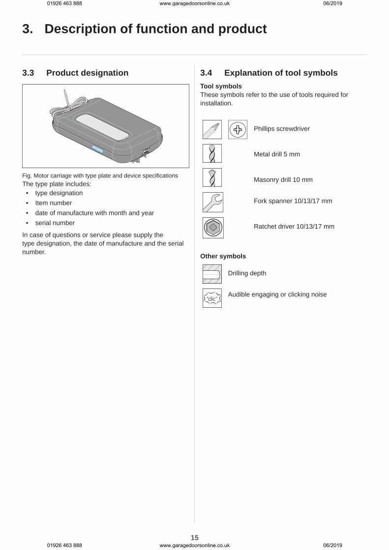
3.3 Product designation
Fig. Motor carriage with type plate and device specificationsThe type plate includes:
• type designation• Item number• date of manufacture with month and year• serial number
In case of questions or service please supply the type designation, the date of manufacture and the serial number.
3.4 Explanation of tool symbolsTool symbolsThese symbols refer to the use of tools required for installation.
Phillips screwdriver
Metal drill 5 mm
Masonry drill 10 mm
Fork spanner 10/13/17 mm
Ratchet driver 10/13/17 mm
Other symbols
Drilling depth
“clic”Audible engaging or clicking noise
01926 463 888 www.garagedoorsonline.co.uk 06/2019
01926 463 888 www.garagedoorsonline.co.uk 06/2019

16
3. Description of function and product
3.5 Scope of delivery
1612
1013
14
15
23
2.1
3
4
2
1
6
8
10
712
9
11
17
5
24
11
22
21 20
1819
Fig. Scope of delivery
1) Ceiling control unit
2) Track, pre-assembled with 1 x guide idler, chain and motor carriage
2.1) Isolator, pre-assembled on the chain
3) Connecting sleeves, 2 x
4) Track, 2 x
5) Plug-in unit, pre-assembled
6) Ceiling holder, 2-part
7) Perforated strip, angled, 2 x
8) Screw M8 x 20 mm, 2 x
9) Hexagonal nut self-locking M8, 2 x
10) S10 wall plugs, 4 x
11) Washer, 4 x
12) Screw 8 x 60 mm, 4 x
13) Lintel bracket, 2 x
14) Hexagonal nut, self-locking M10
15) Hexagonal head screw M10 x 100 mm
16) Emergency release handle
17) Push arm, straight
18) Safety bolt 10 mm, 2 x
19) Bolt 10 x 34.5 mm, 2 x
20) Door bracket
21) Combination self-tapping screw, 4 x
22) Handheld transmitter, preprogrammed, channel 1 pulse sequence, with CR 2032, 3 V lithium battery
23) Information sticker for garage interior
24) Installation and Operating Manual
When unpacking make sure that all articles are included in the packages. If anything is missing, contact your specialist dealer. The actual scope of delivery may vary depending on the type or customer specifications.
01926 463 888 www.garagedoorsonline.co.uk 06/2019
01926 463 888 www.garagedoorsonline.co.uk 06/2019
17
3. Description of function and product
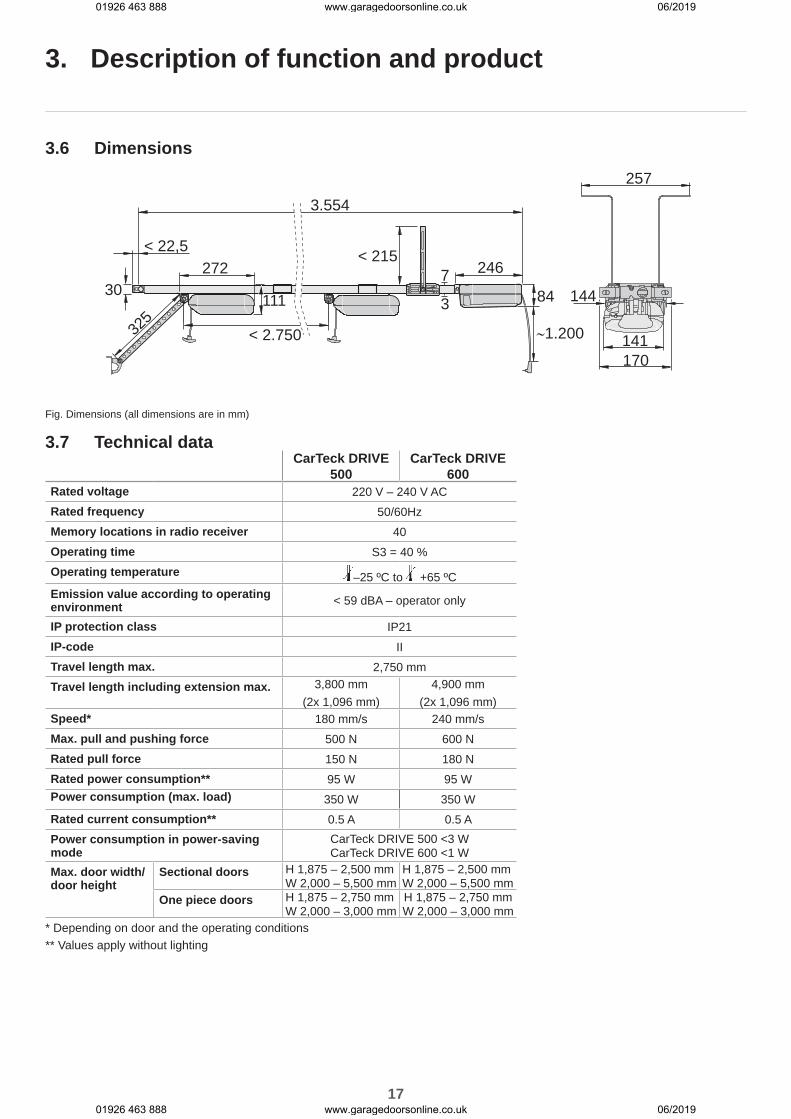
3.6 Dimensions257
170141
144
246
84
3.554
< 215< 22,5272
11130
325
< 2.750
7
3
∼1.200
Fig. Dimensions (all dimensions are in mm)
3.7 Technical dataCarTeck DRIVE
500CarTeck DRIVE
600Rated voltage 220 V – 240 V ACRated frequency 50/60HzMemory locations in radio receiver 40Operating time S3 = 40 %Operating temperature –25 ºC to +65 ºCEmission value according to operating environment < 59 dBA – operator only
IP protection class IP21IP-code IITravel length max. 2,750 mmTravel length including extension max. 3,800 mm
(2x 1,096 mm)4,900 mm
(2x 1,096 mm)Speed* 180 mm/s 240 mm/sMax. pull and pushing force 500 N 600 NRated pull force 150 N 180 NRated power consumption** 95 W 95 WPower consumption (max. load) 350 W 350 WRated current consumption** 0.5 A 0.5 APower consumption in power-saving mode
CarTeck DRIVE 500 <3 W CarTeck DRIVE 600 <1 W
Max. door width/door height
Sectional doors H 1,875 – 2,500 mm W 2,000 – 5,500 mm
H 1,875 – 2,500 mm W 2,000 – 5,500 mm
One piece doors H 1,875 – 2,750 mm W 2,000 – 3,000 mm
H 1,875 – 2,750 mm W 2,000 – 3,000 mm
* Depending on door and the operating conditions** Values apply without lighting
01926 463 888 www.garagedoorsonline.co.uk 06/2019
01926 463 888 www.garagedoorsonline.co.uk 06/2019

18
3.8 Door types and accessoriesDoor type Accessories
One piece door No accessories required
Sectional door with single track
Sectional door fitting with curved push arm*
Sectional door with double track
Sectional door fitting without curved push arm**
Sectional overhead door
No accessories required
Up-and-over door
Curved arm*
Side-opening door, side-opening sectional door
Side-opening/Side-opening sectional door fitting**
* Accessories not included in the scope of delivery** The standard fitting can also be used depending on the installation type. Custom fittings are not included in the scope of delivery.
A number of accessories are available for the operator.
Here are a few examples:Accessories FunctionSenso Pluggable humidity sensor
If humidity is high, the garage door automatically opens a bit, providing ventilation
Memo(red housing)
Pluggable EEPROMMemory for expanding the capacity of transmitter commands from 40 internal to 450 external
Lock Pluggable locking magnetFor mechanical locking of the motor and therefore improvement of break-in protection
Alarm/warning buzzer
Pluggable acoustic signal generatorOption of alarm tone when a break-in attempt occurs or a warning tone in the case of a wicket door contact, for example
Laser Pluggable parking position laserThe parking end position is displayed by a laser point on the dashboard
Battery pack AccumulatorOperator is supplied with power during a power failure
For more information on accessories such as track extensions, additional locking mechanism, custom fittings or different transmitters, contact your specialist dealer or see:www.sommer.eu
3. Description of function and product
01926 463 888 www.garagedoorsonline.co.uk 06/2019
01926 463 888 www.garagedoorsonline.co.uk 06/2019

19
4. Tools and protective equipment
4.1 Required tools and personal protective equipment
10 mm13 mm17 mm
5 mm 10 mm
10 mm13 mm17 mm 2x
Fig. Recommended tools and personal protective equipment for installationYou will require the tools shown above to assemble and install the operator. Lay out the required tools beforehand to ensure fast and safe installation.
WARNINGRisk of eye injury!Chips flying when drilling may cause serious injuries to eyes and hands.
► Wear safety glasses when drilling.
WARNINGRisk of injury in the head region!Impact with suspended objects may cause serious abrasions and cuts.
► You must wear a safety helmet when installing suspended parts.
CAUTIONRisk of injury to hands!Rough metal parts may cause abrasions and cuts when picked up or touched.
► Wear safety gloves when deburring or performing similar work.
Wear your personal protective equipment. This includes safety glasses, safety gloves and a safety helmet.
01926 463 888 www.garagedoorsonline.co.uk 06/2019
01926 463 888 www.garagedoorsonline.co.uk 06/2019

20
5. Declaration of Installation
Declaration of Installationfor the installation of an incomplete machine
in accordance with the Machinery Directive 2006/42/EC, Annex II, Section 1 B
SOMMER Antriebs- und Funktechnik GmbHHans-Böckler-Straße 21–27
73230 KirchheimGermany
hereby declares that the control units
CarTeck DRIVE 500, CarTeck DRIVE 600
have been developed, designed and manufactured in conformity with the:• Machinery Directive 2006/42/EC• Low Voltage Directive 2014/35/EU• Electromagnetic Compatibility Directive 2014/30/EU• RoHS Directive 2011/65/EU
The following standards were applied:• EN ISO 13849-1, PL "C" Cat. 2 Safety of machines - safety-related parts of controls - Part 1: General
design guidelines• EN 60335-1, where applicable Safety of electrical appliances/operators for doors• EN 61000-6-3 Electromagnetic compatibility (EMC) - interference• EN 61000-6-2 Electromagnetic compatibility (EMC) - interference resistance• EN 60335-2-95 General safety requirements for household and similar electrical appliances
- Part 2: Particular requirements for operators for vertically moving garage doors for residential use
• EN 60335-2-103 General safety requirements for household and similar electrical appliances - Part 2: Special requirements for operators for gates, doors and windows
The following requirements of Annex 1 of the Machinery Directive 2006/42/EC are met:1.1.2, 1.1.3, 1.1.5, 1.2.1, 1.2.2, 1.2.3, 1.2.4, 1.2.5, 1.2.6, 1.3.1, 1.3.2, 1.3.4, 1.3.7, 1.5.1, 1.5.4, 1.5.6, 1.5.14, 1.6.1, 1.6.2, 1.6.3, 1.7.1, 1.7.3, 1.7.4 The special technical documents have been prepared in accordance with Annex VII Part B and are submitted electronically to the regulators on request.
The incomplete machine is intended for installation in a door system only to form a complete machine as defined by the Machinery Directive 2006/42/EC. The door system may only be put into operation after it has been established that the complete system complies with the regulations of the above EC Directive.
The undersigned is responsible for compilation of the technical documents.
Kirchheim, 01-12-2017
i.V.
Jochen Lude Responsible for documents
01926 463 888 www.garagedoorsonline.co.uk 06/2019
01926 463 888 www.garagedoorsonline.co.uk 06/2019

21
6. Installation
6.1 Important information on installation
In particular, please observe and comply with the following safety instructions to ensure safe installation.People under the influence of drugs, alcohol, or medications that can influence their ability to react may not work on the operator.The installation of the operator may only be performed by a qualified specialist.This installation and operating manual must be read, understood and complied with by a qualified specialist who installs the operator.
DANGERDanger if not observed!If safety instructions are not observed, serious injury or death may result.
► All safety instructions must be complied with.
WARNINGDanger of falling!Unsafe or defective ladders may tip and cause serious or fatal accidents.
► Use only a non-slip, stable ladder. ► Ensure that ladders are safely positioned.
WARNINGDanger for trapped persons!Persons may be trapped inside the garage. If trapped persons cannot free themselves, severe injury or death may result.
► Test the operation of the emergency release regularly from inside and if necessary, also from outside.
► If there is no second entrance to the garage, you must have a release lock or a Bowden wire for unlocking from the outside installed. This can be used to free persons who cannot free themselves.
WARNINGDanger due to projecting parts!Gate leaves or other parts must not project into public roads or footpaths. This also applies while the door is moving.This may cause serious injury or death to persons or animals.
► Keep public roads and footpaths clear of projecting parts.
WARNINGDanger due to falling parts of doors!If a door is incorrectly balanced, springs may break suddenly. Falling door parts may cause serious injury or death.Check:
► the stability of the door. ► that the door does not bend, rotate or twist when you open or close it.
► that the door runs smoothly in the tracks.
WARNINGDanger due to falling ceiling and wall parts!The operator cannot be installed correctly if ceiling and walls are unstable or if unsuitable mounting materials are used. Persons or animals may be struck by falling parts of the wall, ceiling or operator. Severe injuries or death may result.
► You must test the stability of the ceiling and the walls.
► Use only permissible mounting materials appropriate for the supporting surface.
WARNINGDanger of entrapment!Loose clothing or long hair may be trapped by moving parts of the door. Severe injuries or death may result.
► Keep clear of the moving door. ► Always wear tight-fitting clothing. ► Wear a hairnet if you have long hair.
01926 463 888 www.garagedoorsonline.co.uk 06/2019
01926 463 888 www.garagedoorsonline.co.uk 06/2019
22
6. Installation
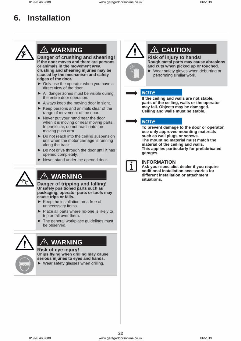
WARNINGDanger of crushing and shearing!If the door moves and there are persons or animals in the movement area, crushing and shearing injuries may be caused by the mechanism and safety edges of the door.
► Only use the operator when you have a direct view of the door.
► All danger zones must be visible during the entire door operation.
► Always keep the moving door in sight. ► Keep persons and animals clear of the range of movement of the door.
► Never put your hand near the door when it is moving or near moving parts. In particular, do not reach into the moving push arm.
► Do not reach into the ceiling suspension unit when the motor carriage is running along the track.
► Do not drive through the door until it has opened completely.
► Never stand under the opened door.
WARNINGDanger of tripping and falling!Unsafely positioned parts such as packaging, operator parts or tools may cause trips or falls.
► Keep the installation area free of unnecessary items.
► Place all parts where no-one is likely to trip or fall over them.
► The general workplace guidelines must be observed.
WARNINGRisk of eye injury!Chips flying when drilling may cause serious injuries to eyes and hands.
► Wear safety glasses when drilling.
CAUTIONRisk of injury to hands!Rough metal parts may cause abrasions and cuts when picked up or touched.
► Wear safety gloves when deburring or performing similar work.
NOTEIf the ceiling and walls are not stable, parts of the ceiling, walls or the operator may fall. Objects may be damaged.Ceiling and walls must be stable.
NOTETo prevent damage to the door or operator, use only approved mounting materials such as wall plugs or screws.The mounting material must match the material of the ceiling and walls.This applies particularly for prefabricated garages.
INFORMATIONAsk your specialist dealer if you require additional installation accessories for different installation or attachment situations.
01926 463 888 www.garagedoorsonline.co.uk 06/2019
01926 463 888 www.garagedoorsonline.co.uk 06/2019
23
6. Installation
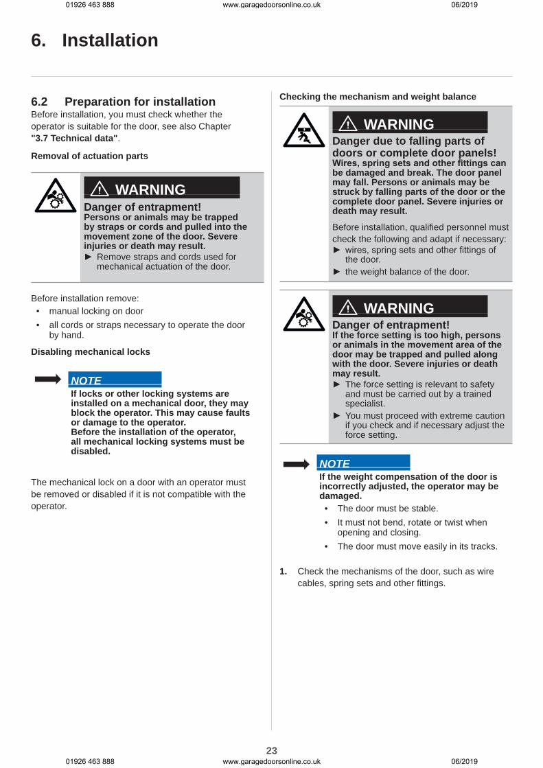
6.2 Preparation for installationBefore installation, you must check whether the operator is suitable for the door, see also Chapter "3.7 Technical data".
Removal of actuation parts
WARNINGDanger of entrapment!Persons or animals may be trapped by straps or cords and pulled into the movement zone of the door. Severe injuries or death may result.
► Remove straps and cords used for mechanical actuation of the door.
Before installation remove:• manual locking on door• all cords or straps necessary to operate the door
by hand.
Disabling mechanical locks
NOTEIf locks or other locking systems are installed on a mechanical door, they may block the operator. This may cause faults or damage to the operator.Before the installation of the operator, all mechanical locking systems must be disabled.
The mechanical lock on a door with an operator must be removed or disabled if it is not compatible with the operator.
Checking the mechanism and weight balance
WARNINGDanger due to falling parts of doors or complete door panels!Wires, spring sets and other fittings can be damaged and break. The door panel may fall. Persons or animals may be struck by falling parts of the door or the complete door panel. Severe injuries or death may result.Before installation, qualified personnel must check the following and adapt if necessary:
► wires, spring sets and other fittings of the door.
► the weight balance of the door.
WARNINGDanger of entrapment!If the force setting is too high, persons or animals in the movement area of the door may be trapped and pulled along with the door. Severe injuries or death may result.
► The force setting is relevant to safety and must be carried out by a trained specialist.
► You must proceed with extreme caution if you check and if necessary adjust the force setting.
NOTEIf the weight compensation of the door is incorrectly adjusted, the operator may be damaged.
• The door must be stable.• It must not bend, rotate or twist when
opening and closing.• The door must move easily in its tracks.
1. Check the mechanisms of the door, such as wire cables, spring sets and other fittings.
01926 463 888 www.garagedoorsonline.co.uk 06/2019
01926 463 888 www.garagedoorsonline.co.uk 06/2019
24
6. Installation
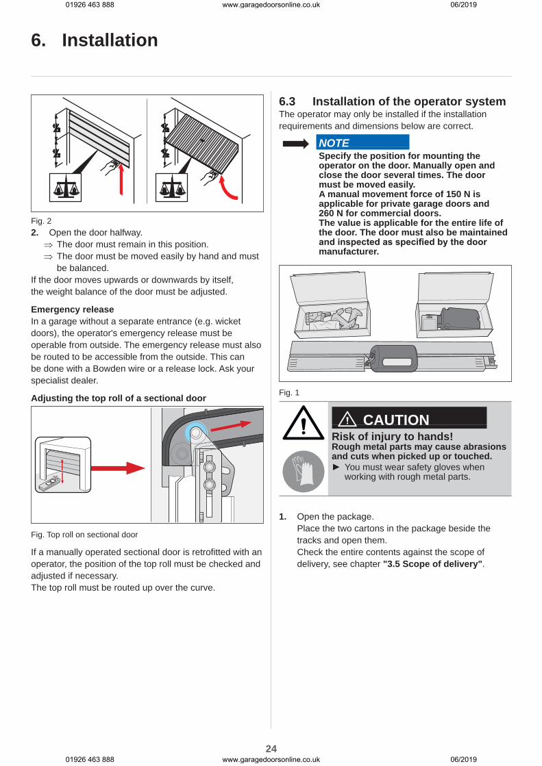
Fig. 22. Open the door halfway.
⇒ The door must remain in this position. ⇒ The door must be moved easily by hand and must be balanced.
If the door moves upwards or downwards by itself, the weight balance of the door must be adjusted.
Emergency releaseIn a garage without a separate entrance (e.g. wicket doors), the operator's emergency release must be operable from outside. The emergency release must also be routed to be accessible from the outside. This can be done with a Bowden wire or a release lock. Ask your specialist dealer.
Adjusting the top roll of a sectional door
Fig. Top roll on sectional door
If a manually operated sectional door is retrofitted with an operator, the position of the top roll must be checked and adjusted if necessary.The top roll must be routed up over the curve.
6.3 Installation of the operator systemThe operator may only be installed if the installation requirements and dimensions below are correct.
NOTESpecify the position for mounting the operator on the door. Manually open and close the door several times. The door must be moved easily.A manual movement force of 150 N is applicable for private garage doors and 260 N for commercial doors.The value is applicable for the entire life of the door. The door must also be maintained and inspected as specified by the door manufacturer.
Fig. 1
CAUTIONRisk of injury to hands!Rough metal parts may cause abrasions and cuts when picked up or touched.
► You must wear safety gloves when working with rough metal parts.
1. Open the package.Place the two cartons in the package beside the tracks and open them.Check the entire contents against the scope of delivery, see chapter "3.5 Scope of delivery".
01926 463 888 www.garagedoorsonline.co.uk 06/2019
01926 463 888 www.garagedoorsonline.co.uk 06/2019
25
“clic”
“clic”
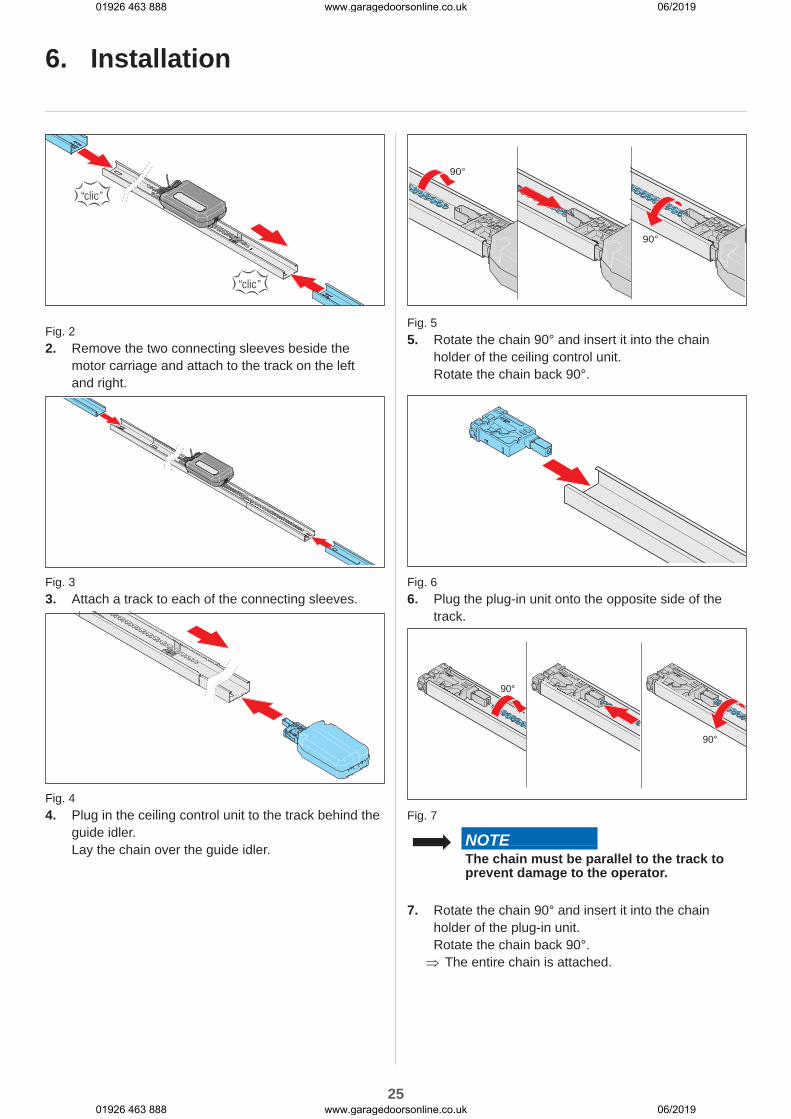
Fig. 22. Remove the two connecting sleeves beside the
motor carriage and attach to the track on the left and right.
Fig. 33. Attach a track to each of the connecting sleeves.
Fig. 44. Plug in the ceiling control unit to the track behind the
guide idler.Lay the chain over the guide idler.
90°
90°
Fig. 55. Rotate the chain 90° and insert it into the chain
holder of the ceiling control unit.Rotate the chain back 90°.
Fig. 66. Plug the plug-in unit onto the opposite side of the
track.
90°
90°
Fig. 7
NOTEThe chain must be parallel to the track to prevent damage to the operator.
7. Rotate the chain 90° and insert it into the chain holder of the plug-in unit.Rotate the chain back 90°. ⇒ The entire chain is attached.
6. Installation
01926 463 888 www.garagedoorsonline.co.uk 06/2019
01926 463 888 www.garagedoorsonline.co.uk 06/2019

26
10 mm 17 mm 17 mm
Fig. 8 Fig. 98. Tension the chain to the mark on the plug-in unit,
see arrow in the detailed view.
9. Screw the two header brackets to the plug-in unit with bolt and nut.
13 mm
BACKHINTEN
100 mm -700 mm
Fig. 10 Fig. 1110. Turn the track to install the ceiling bracket.
The distance between the ceiling control unit and the ceiling holder should be 100 - 700 mm.Place the ceiling holder on the track and slide into one another.
11. Fasten the perforated strips to the ceiling holder on the right and left. Also observe the distances for installation to the ceiling or lintel. ⇒ The track is prepared for the remainder of the installation.
For further installation, see Chapter "6.4 Installation on the door".
6.4 Installation on the doorINFORMATIONBecause the track of the operator and the rear distance track are on the same level, the distance track must be severed and displaced.
b
b
c
c
Version 1
C = 120 - 160
6. Installation
01926 463 888 www.garagedoorsonline.co.uk 06/2019
01926 463 888 www.garagedoorsonline.co.uk 06/2019

27
6. Installation
Version 2
C = 120 - 160
Version 3
C = 120 - 160
b
!b - 40
X
5-6
5 m
m
min
.35
mm
X
Fig. 1.1 Highest point for one piece and up-and-over doors
X
5-6
5 m
m
min
.35
mm
X
Fig. 1.2 Highest point for a sectional door
INFORMATIONIf the distance between the ceiling and the bottom edge of the track is greater than 245 mm, extend the ceiling holder with additional perforated strips.
1. Measure the highest point of the door "X" depending on the type of door:Open the door and measure the closest distance (min. 35 mm) between the top edge of the door and the ceiling.The distance between "X" and the bottom edge of the track must be at least 5 mm and no more than 65 mm.
max. 30°
Fig. 2
01926 463 888 www.garagedoorsonline.co.uk 06/2019
01926 463 888 www.garagedoorsonline.co.uk 06/2019

28
6. Installation
INFORMATIONThe distance may be reduced if a door handle is attached to the middle of the door. The door must be able to run freely.
2. The push arm must be at a max. angle of 30° with the door closed.
½ ½½ ½70 mm 70 mm
21 mm
Fig. 3 Fig. 43. Close the door.
Select the lintel or ceiling for installation. Measure the centre of the door at the front and mark the position on the door and the lintel or ceiling.
4. Mark points 70 mm to the right and left of the centre of the door at the same height on the lintel or ceiling.
30 mmmin.15 mm
15 m
m
10 mm 65 mm15
½ ½½ ½
Fig. 5 Fig. 6
NOTECover the operator during drilling to prevent dirt from entering the operator unit and damaging it.
INFORMATIONIf installing on the ceiling, space the drill holes 15 mm apart if possible. This reduces the tilting angle of the mounting bracket.
INFORMATIONThe drilling depth must be considered concerning the ceiling and wall thickness, particularly with prefabricated garages. It may be necessary to reduce the hole depth.Only use permissible mounting materials appropriate for the supporting surface.
5. Drill two holes (Ø 10 x 65 mm deep) in the ceiling or lintel.
6. Open the door.Transfer the mark from the centre of the door to the ceiling at the rear.
13 mm
Fig. 77. Close the door.
Insert the wall plug into the lintel or ceiling. Lift the track at the front.Screw the lintel fitting at the front to the lintel or ceiling with two screws and the washers. Tighten the screws. ⇒ The track is attached to the lintel or ceiling.
X
X
Fig. 8
NOTEThe operator must always be installed parallel to the tracks of the door to prevent damage to the operator and the tracks.
8. Align the operator parallel to the tracks of the door.
01926 463 888 www.garagedoorsonline.co.uk 06/2019
01926 463 888 www.garagedoorsonline.co.uk 06/2019

29
100 mm
700 mm
10 mm
65 mm
13 mm
Fig. 9 Fig. 109. Align the track parallel to centre of the door at
the rear.Align the ceiling bracket.The distance between the ceiling control unit and the ceiling holder should be 100 - 700 mm. The ceiling bracket should be installed in this area.Check the alignment of the track with a spirit level if necessary.
10. Mark the holes on the ceiling for the ceiling holder.Drill two holes (Ø 10 x 65 mm deep).Insert the wall plugs.Insert two screws with washers and screw the perforated strip to the ceiling.Tighten the screws. ⇒ The track is attached to the ceiling.
Fig. 11
CAUTIONRisk of injury to hands!Rough, projecting metal parts may cause abrasions and cuts when picked up or touched.
► The projecting perforated strips must be sawn off and deburred to prevent injury.
► Wear safety gloves when deburring.
11. The projecting perforated strips must be shortened.
< 1,8 m
2x
Fig. 12
WARNINGDanger of entrapment!Persons or animals in the movement area of the door may be trapped in a loop of the emergency release cord and the door may be accidentally unlocked. Severe injuries or death may result.
► The emergency release handle which is included must be used.
NOTEThe emergency release handle may cause damage, e.g. scratches on the vehicle.The distance between the garage floor and the emergency release cord must be less than 1.8 m.The emergency release handle must be at least 50 mm from moving and fixed parts throughout its complete path.
12. Attach the emergency release handle:Pull the cord through the emergency release handle. Tie a double knot in the cord at an appropriate point. Pull the emergency release handle over the double knot. If necessary, shorten the cord or lengthen it with suitable materials.
6. Installation
01926 463 888 www.garagedoorsonline.co.uk 06/2019
01926 463 888 www.garagedoorsonline.co.uk 06/2019
30
6. Installation
“clic”
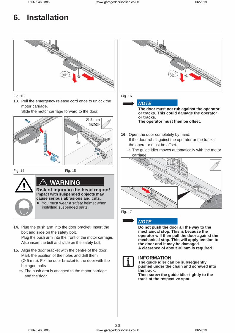
Fig. 1313. Pull the emergency release cord once to unlock the
motor carriage.Slide the motor carriage forward to the door.
5 mm
Fig. 14 Fig. 15
WARNINGRisk of injury in the head region!Impact with suspended objects may cause serious abrasions and cuts.
► You must wear a safety helmet when installing suspended parts.
14. Plug the push arm into the door bracket. Insert the bolt and slide on the safety bolt.Plug the push arm into the front of the motor carriage. Also insert the bolt and slide on the safety bolt.
15. Align the door bracket with the centre of the door.Mark the position of the holes and drill them (Ø 5 mm). Fix the door bracket to the door with the hexagon bolts. ⇒ The push arm is attached to the motor carriage and the door.
“clic”
Fig. 16
NOTEThe door must not rub against the operator or tracks. This could damage the operator or tracks.The operator must then be offset.
16. Open the door completely by hand.If the door rubs against the operator or the tracks, the operator must be offset. ⇒ The guide idler moves automatically with the motor carriage.
Fig. 17
NOTEDo not push the door all the way to the mechanical stop. This is because the operator will then pull the door against the mechanical stop. This will apply tension to the door and it may be damaged.A clearance of about 30 mm is required.
INFORMATIONThe guide idler can be subsequently pushed under the chain and screwed into the track.Then screw the guide idler tightly to the track at the respective spot.
01926 463 888 www.garagedoorsonline.co.uk 06/2019
01926 463 888 www.garagedoorsonline.co.uk 06/2019
31
6. Installation
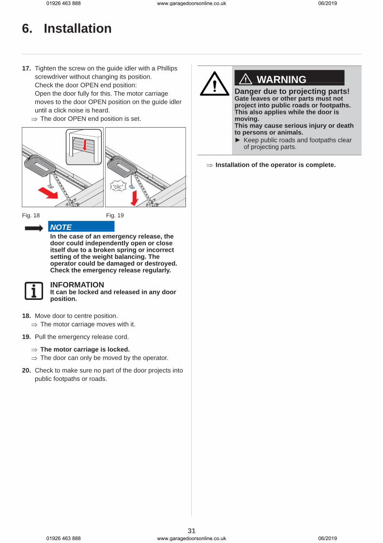
17. Tighten the screw on the guide idler with a Phillips screwdriver without changing its position.Check the door OPEN end position:Open the door fully for this. The motor carriage moves to the door OPEN position on the guide idler until a click noise is heard. ⇒ The door OPEN end position is set.
“clic”
Fig. 18 Fig. 19
NOTEIn the case of an emergency release, the door could independently open or close itself due to a broken spring or incorrect setting of the weight balancing. The operator could be damaged or destroyed.Check the emergency release regularly.
INFORMATIONIt can be locked and released in any door position.
18. Move door to centre position. ⇒ The motor carriage moves with it.
19. Pull the emergency release cord.
⇒ The motor carriage is locked. ⇒ The door can only be moved by the operator.
20. Check to make sure no part of the door projects into public footpaths or roads.
WARNINGDanger due to projecting parts!Gate leaves or other parts must not project into public roads or footpaths. This also applies while the door is moving.This may cause serious injury or death to persons or animals.
► Keep public roads and footpaths clear of projecting parts.
⇒ Installation of the operator is complete.
01926 463 888 www.garagedoorsonline.co.uk 06/2019
01926 463 888 www.garagedoorsonline.co.uk 06/2019
32
7. Removing and fastening covers
7.1 Cover of the motor carriageObserve in particular the following safety instructions for this chapter.
WARNINGDanger due to optical radiation!Looking into an LED at short range for an extended period may cause optical glare. This may temporarily reduce vision. This may cause serious or fatal accidents.
► Never look directly into an LED.
WARNINGDanger due to hot surfaces!After frequent operation parts of the motor carriage or the control unit may become hot. If the cover is removed and hot parts are touched, they may cause burns.
► Allow the operator to cool down before removing the cover.
Removing cover
Fig. 1
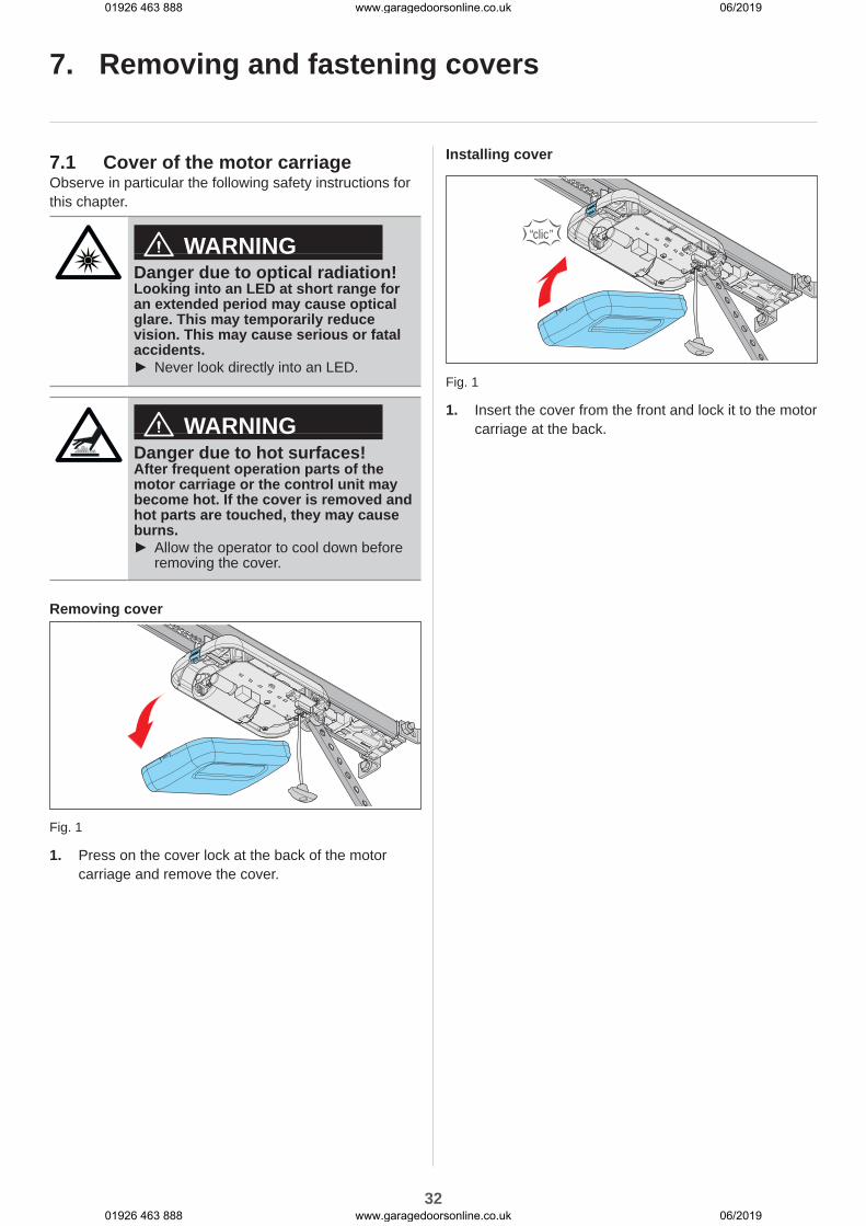
1. Press on the cover lock at the back of the motor carriage and remove the cover.
Installing cover
“clic”
Fig. 1
1. Insert the cover from the front and lock it to the motor carriage at the back.
01926 463 888 www.garagedoorsonline.co.uk 06/2019
01926 463 888 www.garagedoorsonline.co.uk 06/2019
33
7. Removing and fastening covers
7.2 Cover of the ceiling control unitObserve in particular the following safety instructions for this chapter.
DANGERDanger due to electric current!Contact with live parts may result in electric current flowing through the body. Electric shock, burns or death will result.
► All work on electrical components may only be carried out by a trained electrician.
► Disconnect the mains plug before working on the operator.
► If an accumulator is connected, disconnect it from the control unit.
► Check that the operator is not live. ► Secure the operator against being switched back on.
WARNINGDanger due to hot surfaces!After frequent operation parts of the motor carriage or the control unit may become hot. If the cover is removed and hot parts are touched, they may cause burns.
► Allow the operator to cool down before removing the cover.
Unscrewing cover
< 1100 mm
Fig. 1
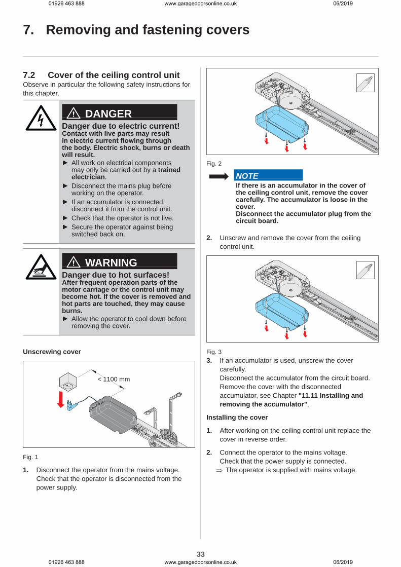
1. Disconnect the operator from the mains voltage.Check that the operator is disconnected from the power supply.
Fig. 2
NOTEIf there is an accumulator in the cover of the ceiling control unit, remove the cover carefully. The accumulator is loose in the cover.Disconnect the accumulator plug from the circuit board.
2. Unscrew and remove the cover from the ceiling control unit.
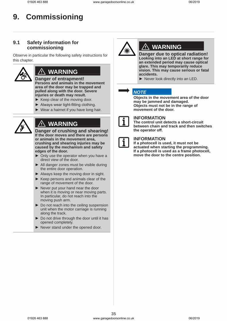
Fig. 33. If an accumulator is used, unscrew the cover
carefully.Disconnect the accumulator from the circuit board.Remove the cover with the disconnected accumulator, see Chapter "11.11 Installing and removing the accumulator".
Installing the cover
1. After working on the ceiling control unit replace the cover in reverse order.
2. Connect the operator to the mains voltage. Check that the power supply is connected. ⇒ The operator is supplied with mains voltage.
01926 463 888 www.garagedoorsonline.co.uk 06/2019
01926 463 888 www.garagedoorsonline.co.uk 06/2019

34
8. Electrical connection
8.1 Connection to a power socketA power socket is required for the electrical connection of the operator.A power socket must be installed by trained electricians only. The power socket must be protected by a fuse. Local and national regulations must be observed (e.g. VDE).People under the influence of drugs, alcohol, or medications that can influence their ability to react may not work on the operator.Observe in particular the following safety instructions for this chapter.
DANGERDanger due to electric current!Contact with live parts may result in electric current flowing through the body. Electric shock, burns or death will result.
► All work on electrical components may only be carried out by a trained electrician.
► Before inserting the mains power plug for the first time, ensure that the voltage of the power source matches the voltage listed on the operator type plate.
► Do not connect the power supply until installation is complete.
► Disconnect the mains plug before working on the operator.
► If an accumulator is connected, disconnect it from the control unit.
► Check that the operator is not live. ► Secure the operator against being switched back on.
NOTEDo not connect the ceiling control unit to the power supply until the installation is complete to prevent damage to the operator.
< 1100 mm
Fig. Distance of ceiling control unit to power socket
Note that the distance between the ceiling control unit and the power socket must not exceed 1.1 m.
INFORMATIONThe power socket must be installed as follows:
• within easy reach of the ceiling control unit power cable
• easily visible and clear of obstacles
INFORMATIONThe power cable is approx. 1.2 m long.
INFORMATIONThe mains supply line that has been provided may not be shortened or extended.All devices to be connected externally must have a safe isolation of the contacts from the mains voltage supply according to IEC 60364-4-41.Wiring for external devices must be installed in accordance with IEC 60364-4-41.All electrical wiring must be firmly secured to prevent displacement.
01926 463 888 www.garagedoorsonline.co.uk 06/2019
01926 463 888 www.garagedoorsonline.co.uk 06/2019
35
9. Commissioning
9.1 Safety information for commissioning
Observe in particular the following safety instructions for this chapter.
WARNINGDanger of entrapment!Persons and animals in the movement area of the door may be trapped and pulled along with the door. Severe injuries or death may result.
► Keep clear of the moving door. ► Always wear tight-fitting clothing. ► Wear a hairnet if you have long hair.
WARNINGDanger of crushing and shearing!If the door moves and there are persons or animals in the movement area, crushing and shearing injuries may be caused by the mechanism and safety edges of the door.
► Only use the operator when you have a direct view of the door.
► All danger zones must be visible during the entire door operation.
► Always keep the moving door in sight. ► Keep persons and animals clear of the range of movement of the door.
► Never put your hand near the door when it is moving or near moving parts. In particular, do not reach into the moving push arm.
► Do not reach into the ceiling suspension unit when the motor carriage is running along the track.
► Do not drive through the door until it has opened completely.
► Never stand under the opened door.
WARNINGDanger due to optical radiation!Looking into an LED at short range for an extended period may cause optical glare. This may temporarily reduce vision. This may cause serious or fatal accidents.
► Never look directly into an LED.
NOTEObjects in the movement area of the door may be jammed and damaged.Objects must not be in the range of movement of the door.
INFORMATIONThe control unit detects a short-circuit between chain and track and then switches the operator off.
INFORMATIONIf a photocell is used, it must not be actuated when starting the programming.If a photocell is used as a frame photocell, move the door to the centre position.
01926 463 888 www.garagedoorsonline.co.uk 06/2019
01926 463 888 www.garagedoorsonline.co.uk 06/2019
36
9. Commissioning
9.2 Initial operationBefore initial operation, read this chapter with special care to ensure that you can make the adjustments to the operator safely and optimally.
WARNINGDanger of entrapment!If the force setting is too high, persons or animals in the movement area of the door may be trapped and pulled along with the door. Severe injuries or death may result.
► The force setting is relevant to safety and must be carried out by a trained specialist.
► You must proceed with extreme caution if you check and if necessary adjust the force setting.
► Please note that the operator may only be operated if a non-hazardous force value has been set.
► Select the force setting low enough to eliminate any danger of injury by the closing force.
NOTEDo not use a metal object to set the DIP switches, because this may damage the DIP switches or the circuit board.Use a suitable tool to set the DIP switches, such as a flat, thin plastic object.
INFORMATIONThe force setting must be checked after installation of the operator. See also chapter "13.1 Testing obstacle detection."
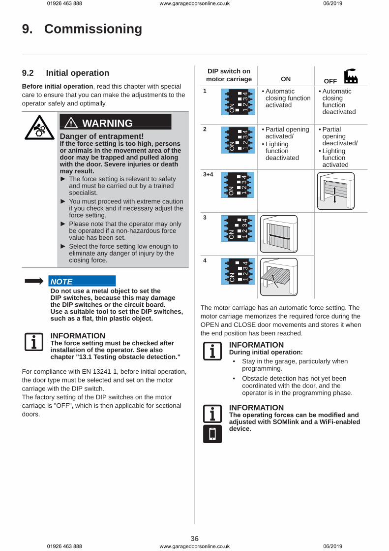
For compliance with EN 13241-1, before initial operation, the door type must be selected and set on the motor carriage with the DIP switch.The factory setting of the DIP switches on the motor carriage is "OFF", which is then applicable for sectional doors.
DIP switch on motor carriage
ON OFF
1
ON 1 2
34
• Automatic closing function activated
• Automatic closing function deactivated
2
ON 1 2
34
• Partial opening activated/
• Lighting function deactivated
• Partial opening deactivated/
• Lighting function activated
3+4
ON 1 2
34
3
ON 1 2
34
4
ON 1 2
34
The motor carriage has an automatic force setting. The motor carriage memorizes the required force during the OPEN and CLOSE door movements and stores it when the end position has been reached.
INFORMATIONDuring initial operation:
• Stay in the garage, particularly when programming.
• Obstacle detection has not yet been coordinated with the door, and the operator is in the programming phase.
INFORMATIONThe operating forces can be modified and adjusted with SOMlink and a WiFi-enabled device.
01926 463 888 www.garagedoorsonline.co.uk 06/2019
01926 463 888 www.garagedoorsonline.co.uk 06/2019

37
< 1100 mm
Fig. 1
1. Compare the existing power supply with the type plate.Connect the operator with the mains voltage. ⇒ The status LED of the motor carriage flashes green.
Fig. 22. After the operator has been connected to the power
supply, its first movement after a pulse is always door OPEN.Press button 1 briefly on the preprogrammed handheld transmitter. See also the separate instructions for the "Handheld transmitter". ⇒ The motor carriage moves slowly to the door OPEN end position and automatically switches off at the guide idler.
⇒ The operator lighting flashes.
Fig. 33. Press button 1 on the handheld transmitter again
briefly.
⇒ The motor carriage moves slowly in the door CLOSE direction.
⇒ The operator lighting flashes.The motor carriage switches off automatically when it reaches the factory-set closing force at the door CLOSE end position.
⇒ The operator lighting flashes in a different sequence.
Fig. 4
4. Press button 1 on the handheld transmitter briefly (< 1 second) to save the end position. ⇒ The operator lighting flashes briefly in a fast sequence.The operator automatically starts its programming process:
⇒ The motor carriage moves automatically to the door OPEN end position again and programs the required operating force.
⇒ The motor carriage automatically moves to the door CLOSE end position.If necessary, the motor carriage moves over the path several times for programming with a greater door weight.
⇒ The motor carriage automatically moves briefly in the door OPEN direction to program the soft run.
⇒ The door automatically returns to the door CLOSE end position.
⇒ The motor carriage automatically moves to the door OPEN end position.
⇒ The LEDs of the operator lighting remain steady. ⇒ Operator is programmed and ready for use.
INFORMATIONThe motor carriage stops if the door is difficult to move. The door mechanism must be checked, see Chapter "9.3 Detecting obstacles during the force programming run."
It may be necessary to readjust the end positions, see Chapter "9.4 Mechanical adjustment of the end positions".
9. Commissioning
01926 463 888 www.garagedoorsonline.co.uk 06/2019
01926 463 888 www.garagedoorsonline.co.uk 06/2019
38
9.3 Detecting obstacles during the force programming run
If the door detects an obstacle during its first door CLOSE movement and the force programming runs cannot be completed, the door stops.
NOTECheck the travel path, mechanism, spring tension and the weight balance to prevent damage to the door system.
1. Press and hold button 1 on the handheld transmitter. ⇒ The motor carriage jerks briefly and moves in the door CLOSE direction until the desired end position has been reached.
2. Release button 1 on the handheld transmitter.
3. Fine adjustment:Press and hold button 1 on the transmitter until the motor carriage jerks briefly.Release button 1 on the handheld transmitter.
3.1 The process can be repeated until the desired end position is reached.Press button 1 on the handheld transmitter briefly (< 1 second) to save the door CLOSE end position. ⇒ The motor carriage starts the automatic force programming runs for the door OPEN end position.
⇒ The motor carriage starts the automatic force programming runs for the door CLOSE end position.
If an obstacle is detected again, the motor carriage stops and reverses a short distance.
1. Press and hold button 1 on the handheld transmitter. ⇒ The motor carriage starts without jerking, because the end position of the door is already saved.
⇒ The motor carriage moves to the end position.
2. Release button 1 on the handheld transmitter.
3. Press button 1 on the handheld transmitter briefly.
⇒ Restart automatic force programming runs. ⇒ On completion of the force programming runs the motor carriage automatically moves to the door OPEN end position.
⇒ The LEDs of the operator lighting remain steady.
⇒ Operator is programmed and ready for use.
9. Commissioning
9.4 Mechanical adjustment of the end positions
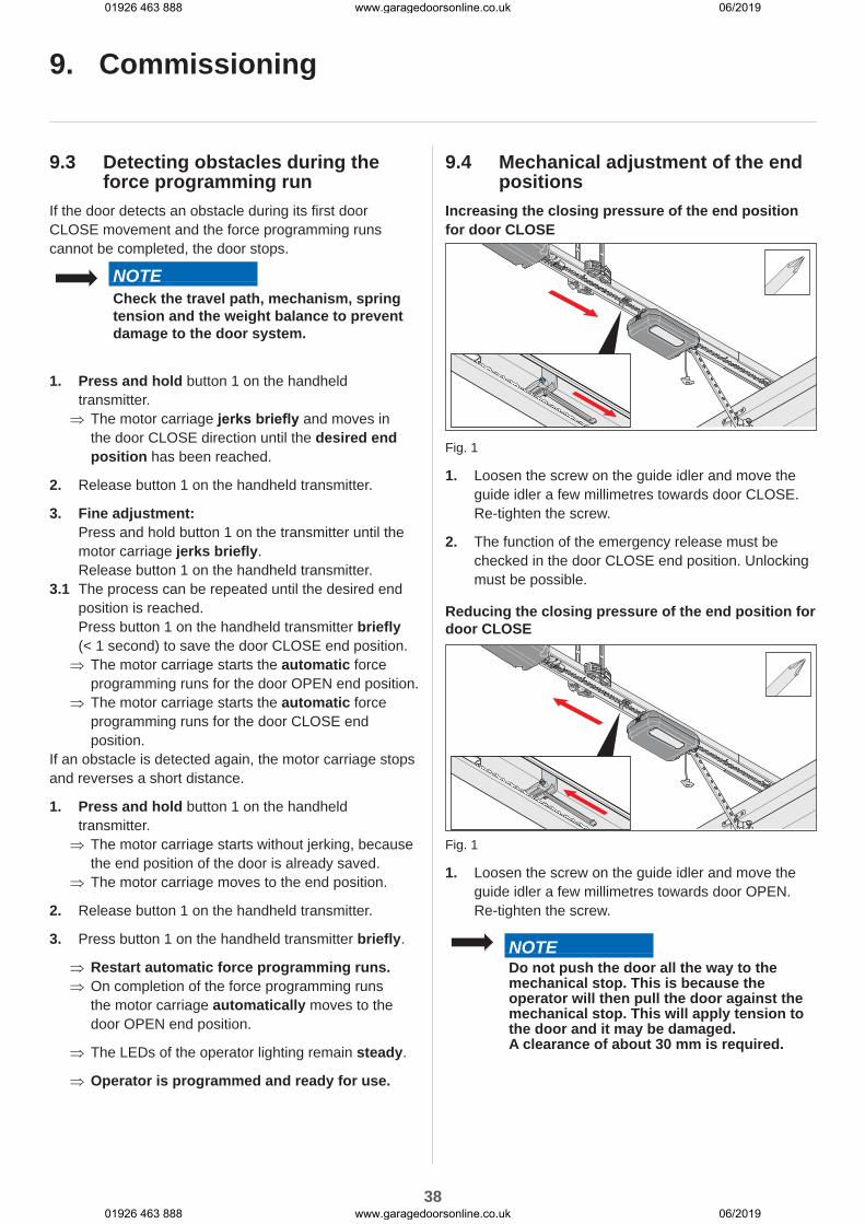
Increasing the closing pressure of the end position for door CLOSE
Fig. 1
1. Loosen the screw on the guide idler and move the guide idler a few millimetres towards door CLOSE. Re-tighten the screw.
2. The function of the emergency release must be checked in the door CLOSE end position. Unlocking must be possible.
Reducing the closing pressure of the end position for door CLOSE
Fig. 1
1. Loosen the screw on the guide idler and move the guide idler a few millimetres towards door OPEN. Re-tighten the screw.
NOTEDo not push the door all the way to the mechanical stop. This is because the operator will then pull the door against the mechanical stop. This will apply tension to the door and it may be damaged.A clearance of about 30 mm is required.
01926 463 888 www.garagedoorsonline.co.uk 06/2019
01926 463 888 www.garagedoorsonline.co.uk 06/2019
39
9.5 Attaching information sign and warning signs
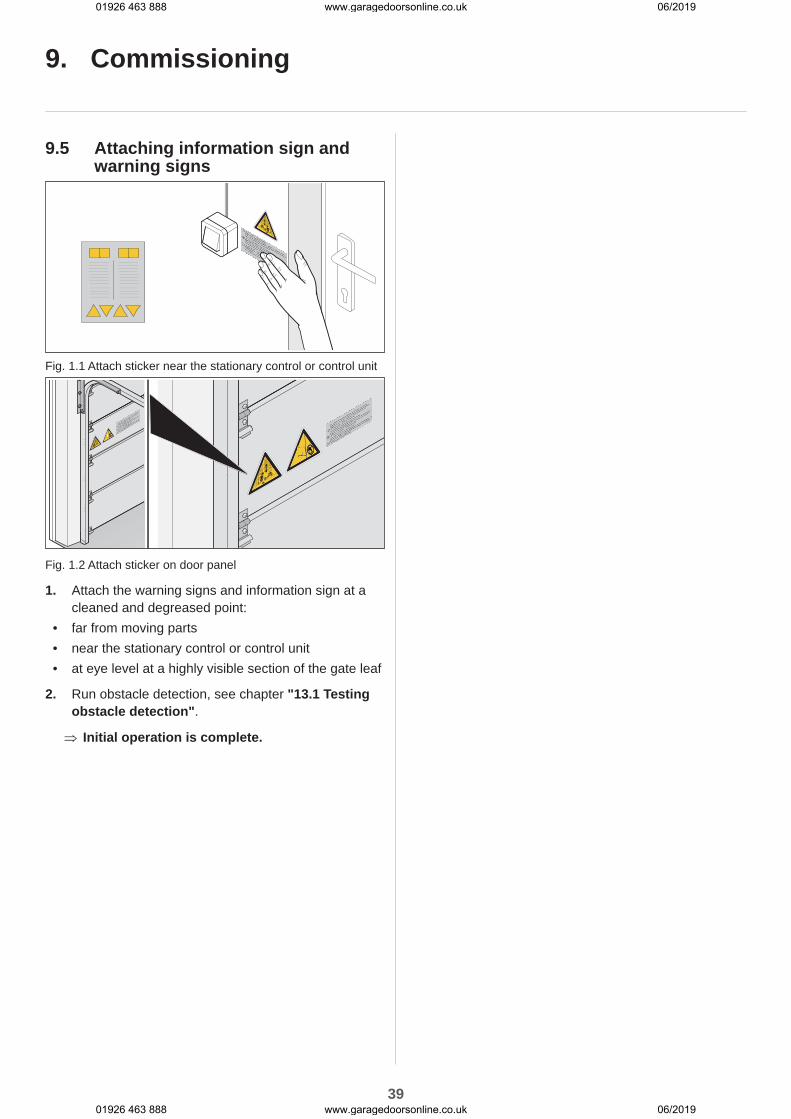
Fig. 1.1 Attach sticker near the stationary control or control unit
Fig. 1.2 Attach sticker on door panel
1. Attach the warning signs and information sign at a cleaned and degreased point:
• far from moving parts• near the stationary control or control unit• at eye level at a highly visible section of the gate leaf
2. Run obstacle detection, see chapter "13.1 Testing obstacle detection".
⇒ Initial operation is complete.
9. Commissioning
01926 463 888 www.garagedoorsonline.co.uk 06/2019
01926 463 888 www.garagedoorsonline.co.uk 06/2019

40
10. Connections and special functions of the motor carriage
10.1 Motor carriage circuit board
ws
gn
LW-APCXXXXXXX
SOMMERAntriebs- u.Funktechnik GmbH
8K2
ws
rtsw
+12V br gn wh
BUZZER
+12V
RADIO
RESET
MEMO
LIM
IT
MAGNET
SENSO
LAS
ER
ON 1 2
34
CH1CH2CH3CH4
STATUS
US
AR
T
OSE
+
-
MO
TIO
N
2
4
3
5
1
16
15 14
13 12 10
11
9 8 7 6
17
Fig. Motor carriage circuit board (complete version*)
Connection options on the motor carriage1 LED, CH 1 - CH 4, red
Display for radio channel10 LASER slot*, white
Parking position laser terminal2 MAGNET slot*, green
Lock terminal11 MOTION slot*, white, 3-pin
Terminal for movement sensor3 LIMIT slot, blue
Limit switch terminal (OPEN)12 Terminal for safety contact strip*
8k2/OSE4 Circuit board label 13 Terminal for wicket door safety device
potential-free5 LEDs, operator lighting 12/13 Terminal 12V DC, max. 100 mA
6 MEMO slot*Memo terminal
14 Status LED, green
7 USART slot*Interface
15 Reset button, green
8 BUZZER slot*, blackWarning or alarm buzzer terminal
16 DIP switches
9 SENSO slot*Senso terminal
17 Radio button, red (radio)
*The version can vary depending on the type. This means the use of accessories can vary
A connection diagram can be found in Chapter “19. Connection diagrams and functions of the DIP switches”.
01926 463 888 www.garagedoorsonline.co.uk 06/2019
01926 463 888 www.garagedoorsonline.co.uk 06/2019
41
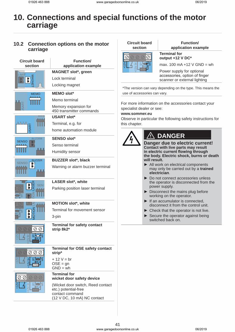
10.2 Connection options on the motor carriage
Circuit board section
Function/application example
LIMIT MA
GN
ET
LIMITMAGNET slot*, greenLock terminalLocking magnet
MEMO
US
AR
TU
SA
RT
MEMO slot*Memo terminalMemory expansion for 450 transmitter commands
MEM
US
AR
T
MEM USART slot*Terminal, e.g. forhome automation module
BUZZERSENSO
BUZZER SENSO slot*Senso terminalHumidity sensor
BUZZERSENSOSENSO
BUZZER slot*, blackWarning or alarm buzzer terminal
8K2 wh
SENS
LAS
ER
TIO
N
SENS
8K2 wh
TIO
N
LASER slot*, whiteParking position laser terminal
8K2 wh
LAS
SE MO
TIO
N
8K2 wh
SEE
LAS MOTION slot*, white
Terminal for movement sensor3-pin
8K2+12V br gn wh
+12V OSE
+12V br
+12V
Terminal for safety contact strip 8k2*
8K2+12V br gn wh
+12V OSE
+12V
Terminal for OSE safety contact strip*+ 12 V = br OSE = gn GND = wh
8K2+12V br gn wh
+12V OSE
8K2
br gn wh
+12V OSEE
Terminal for wicket door safety device(Wicket door switch, Reed contact etc.) potential-free contact command (12 V DC, 10 mA) NC contact
Circuit board section
Function/application example
8K2+12V br gn wh
+12V OSE
8K
br gn
+12V OSE
Terminal for output +12 V DC*max. 100 mA +12 V GND = whPower supply for optional accessories, option of finger scanner or external lighting
*The version can vary depending on the type. This means the use of accessories can vary.
For more information on the accessories contact your specialist dealer or see:www.sommer.euObserve in particular the following safety instructions for this chapter.
DANGERDanger due to electric current!Contact with live parts may result in electric current flowing through the body. Electric shock, burns or death will result.
► All work on electrical components may only be carried out by a trained electrician.
► Do not connect accessories unless the operator is disconnected from the power supply.
► Disconnect the mains plug before working on the operator.
► If an accumulator is connected, disconnect it from the control unit.
► Check that the operator is not live. ► Secure the operator against being switched back on.
10. Connections and special functions of the motor carriage
01926 463 888 www.garagedoorsonline.co.uk 06/2019
01926 463 888 www.garagedoorsonline.co.uk 06/2019

42
10. Connections and special functions of the motor carriage
10.3 Reducing illumination power of LEDs
WARNINGDanger due to optical radiation!Looking into an LED at short range for an extended period may cause optical glare. This may temporarily reduce vision. This may cause serious or fatal accidents.
► Never look directly into an LED.
The illumination power of the LEDs can be reduced during adjustment work by pressing the reset button or radio button once briefly.
1. Press the radio or reset button once briefly. ⇒ Illumination power of LEDs reduced.
10.4 Explanation of the radio channelsLED Radio
channelSetting/function
1 CH 1 Pulse mode
2 CH 2 Partial opening or lighting function
3 CH 3 Defined OPEN
4 CH 4 Defined CLOSE
10.5 Programming the transmitter
RADIO
RESET
CH1CH2CH3CH4
STATUS
ON 1 2
34
Fig. 1
INFORMATIONIf no transmission command is received within 30 seconds after pressing the radio button, the radio receiver switches to normal mode.
1. Press the radio button repeatedly to select the required radio channel.
LED
1 x 2 x 3 x 4 x
CH 1
CH 2
CH 3
CH 4
2. Press the desired button on the transmitter until the previously selected LED (CH 1, CH 2, CH 3, CH 4) is off. ⇒ LED goes out - programming is complete. ⇒ The transmitter has transferred the radio code to the radio receiver.
3. Repeat the above steps to program additional transmitters.
INFORMATIONFurther transmitters cannot be programmed if all memory positions of the handheld transmitter are occupied.
If the memory capacity has been reachedA total of 40 handheld transmitter commands are available for all channels. If an attempt is made to program additional transmitters, the red LEDs of radio channels CH 1 - CH 4 flash. If more memory positions are needed, see Chapter "10.6 Information on Memo".
10.6 Information on MemoThe use of the Memo depends on the version of the motor carriage circuit board.The memory capacity can be extended to 450 handheld transmitter commands using the optional Memo accessory part. When plugging in the Memo, all available transmitters are transferred from the internal memory to the Memo and stored there. The Memo must remain plugged in on the control unit.No more transmitters are stored in the internal memory. Stored transmitters cannot be transferred from the Memo back to the internal memory.All radio channels, including the memory of the Memo, can be deleted, see Chapter "10.11 Deleting all radio channels in the receiver".
INFORMATIONDelete the Memo on a new operator.Otherwise, all stored transmitters of an operator are deleted and must be reprogrammed.
01926 463 888 www.garagedoorsonline.co.uk 06/2019
01926 463 888 www.garagedoorsonline.co.uk 06/2019

43
10. Connections and special functions of the motor carriage
10.7 Cancelling programming mode1. Press the radio button until all LEDs are out or make
no input for 30 seconds. ⇒ Programming mode is cancelled.
10.8 Deleting a transmitter button from the radio channel
1. Press the radio button repeatedly to select the required radio channel.Press and hold the radio button for 15 seconds.
LED
1 x 2 x 3 x 4 x
CH 1
CH 2
CH 3
CH 4
⇒ The LED flashes after 15 seconds.
2. Release the radio button. ⇒ The radio receiver is in deletion mode.
3. Press the transmitter button for which the command is to be deleted in the radio channel. ⇒ LED goes out. ⇒ The deletion procedure is ended.
Repeat the process for additional buttons as required.
10.9 Deleting transmitter completely from the receiver
1. Press and hold the radio button for 20 seconds. ⇒ The LED flashes after 15 seconds. ⇒ After another 5 seconds the flash sequence changes to flashing.
2. Release the radio button. ⇒ The radio receiver is in deletion mode.
3. Press any button on the transmitter that is being deleted. ⇒ LED goes out. ⇒ The deletion procedure is completed. ⇒ The transmitter is deleted from the radio receiver.
Repeat the process for additional transmitters as required.
10.10 Deleting radio channel in the receiver
1. Press the radio button repeatedly to select the required radio channel.Press and hold the radio button for 25 seconds.
LED
1 x 2 x 3 x 4 x
CH 1
CH 2
CH 3
CH 4
⇒ The LED flashes after 15 seconds. ⇒ After another 5 seconds the flash sequence changes to flashing.
⇒ After another 5 seconds, the LED of the selected radio channel remains steady.
2. Release the radio button. ⇒ The deletion procedure is ended. ⇒ All programmed transmitters on the selected radio channel are deleted from the radio receiver.
10.11 Deleting all radio channels in the receiver
1. Press and hold the radio button for 30 seconds. ⇒ The LED flashes after 15 seconds. ⇒ After another 5 seconds the flash sequence changes to flashing.
⇒ After another 5 seconds, the LED of the selected radio channel remains steady.
⇒ After another 5 seconds all LEDs light up.
2. Release the radio button. ⇒ All LEDs are off after 5 seconds. ⇒ All programmed transmitters are deleted from the receiver.
⇒ Receiver is completely deleted, this also applies if the Memo is plugged in.
01926 463 888 www.garagedoorsonline.co.uk 06/2019
01926 463 888 www.garagedoorsonline.co.uk 06/2019
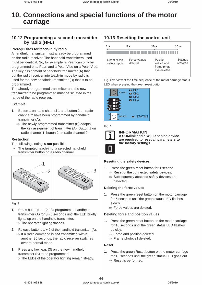
44
10. Connections and special functions of the motor carriage
10.12 Programming a second transmitter by radio (HFL)
Prerequisites for teach-in by radioA handheld transmitter must already be programmed on the radio receiver. The handheld transmitters used must be identical. So, for example, a Pearl can only be programmed on a Pearl and a Pearl Vibe on a Pearl Vibe.The key assignment of handheld transmitter (A) that put the radio receiver into teach-in mode by radio is used for the new handheld transmitter (B) that is to be programmed. The already-programmed transmitter and the new transmitter to be programmed must be situated in the range of the radio receiver.
Example:
1. Button 1 on radio channel 1 and button 2 on radio channel 2 have been programmed by handheld transmitter (A). ⇒ The newly-programmed transmitter (B) adopts the key assignment of transmitter (A): Button 1 on radio channel 1, button 2 on radio channel 2.
RestrictionThe following setting is not possible:
• The targeted teach-in of a selected handheld transmitter button on a radio channel.
12
A3
B
Fig. 1
1. Press buttons 1 + 2 of a programmed handheld transmitter (A) for 3 - 5 seconds until the LED briefly lights up on the handheld transmitter. ⇒ The operator lighting flashes.
2. Release buttons 1 + 2 of the handheld transmitter (A). ⇒ If a radio command is not transmitted within another 30 seconds, the radio receiver switches over to normal mode.
3. Press any key, e.g. (3) on the new handheld transmitter (B) to be programmed. ⇒ The LEDs of the operator lighting remain steady.
10.13 Resetting the control unit
15 s1 s 5 s 10 s
Reset of the safety inputs
Force values deleted
Position values and frame photo eye deleted
Settings restored
Fig. Overview of the time sequence of the motor carriage status LED when pressing the green reset button
RADIO
RESET
CH1CH2CH3CH4
STATUS
ON 1 2
34
Fig. 1
INFORMATIONA SOMlink and a WiFi-enabled device are required to reset all parameters to the factory settings.
Resetting the safety devices
1. Press the green reset button for 1 second. ⇒ Reset of the connected safety devices. ⇒ Subsequently attached safety devices are detected.
Deleting the force values
1. Press the green reset button on the motor carriage for 5 seconds until the green status LED flashes slowly. ⇒ Force values are deleted.
Deleting force and position values
1. Press the green reset button on the motor carriage for 10 seconds until the green status LED flashes quickly. ⇒ Force and position deleted. ⇒ Frame photocell deleted.
Reset
1. Press the green Reset button on the motor carriage for 15 seconds until the green status LED goes out. ⇒ Reset is performed.
01926 463 888 www.garagedoorsonline.co.uk 06/2019
01926 463 888 www.garagedoorsonline.co.uk 06/2019
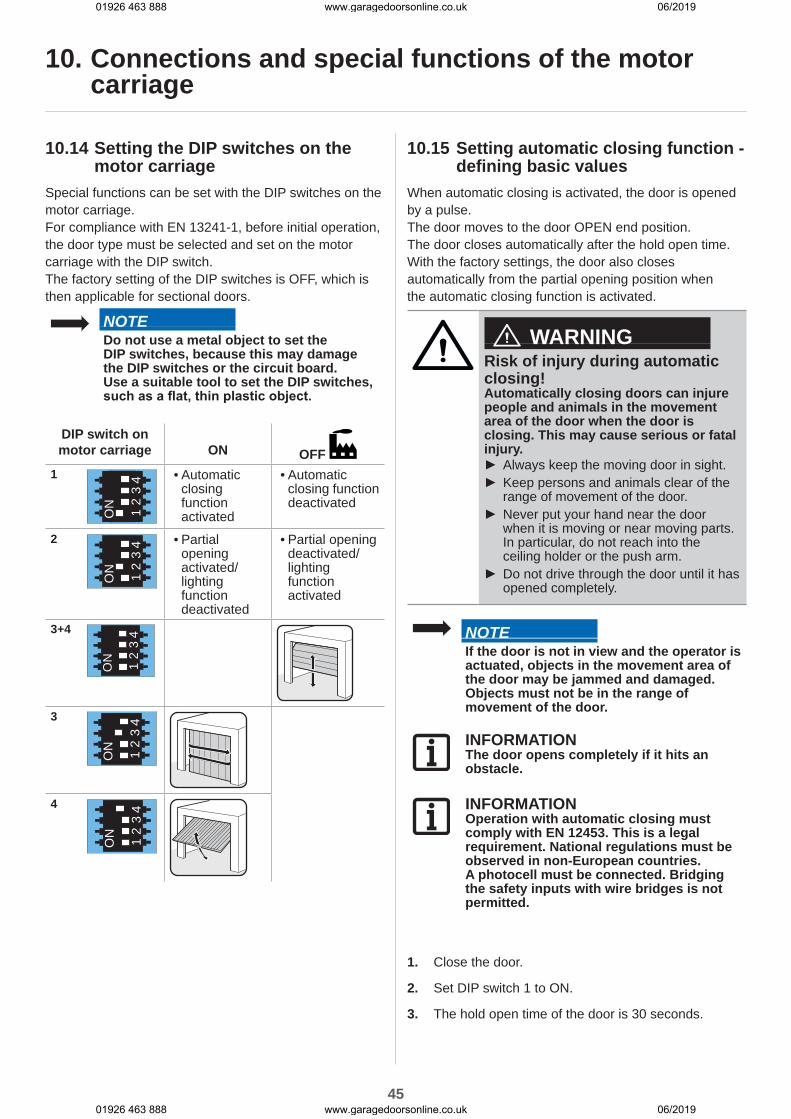
45
10. Connections and special functions of the motor carriage
10.14 Setting the DIP switches on the motor carriage
Special functions can be set with the DIP switches on the motor carriage.For compliance with EN 13241-1, before initial operation, the door type must be selected and set on the motor carriage with the DIP switch.The factory setting of the DIP switches is OFF, which is then applicable for sectional doors.
NOTEDo not use a metal object to set the DIP switches, because this may damage the DIP switches or the circuit board.Use a suitable tool to set the DIP switches, such as a flat, thin plastic object.
DIP switch on motor carriage ON OFF
1
ON 1 2
34 • Automatic
closing function activated
• Automatic closing function deactivated
2
ON 1 2
34
• Partial opening activated/lighting function deactivated
• Partial opening deactivated/lighting function activated
3+4
ON 1 2
34
3
ON 1 2
34
4
ON 1 2
34
10.15 Setting automatic closing function - defining basic values
When automatic closing is activated, the door is opened by a pulse.The door moves to the door OPEN end position. The door closes automatically after the hold open time. With the factory settings, the door also closes automatically from the partial opening position when the automatic closing function is activated.
WARNINGRisk of injury during automatic closing!Automatically closing doors can injure people and animals in the movement area of the door when the door is closing. This may cause serious or fatal injury.
► Always keep the moving door in sight. ► Keep persons and animals clear of the range of movement of the door.
► Never put your hand near the door when it is moving or near moving parts. In particular, do not reach into the ceiling holder or the push arm.
► Do not drive through the door until it has opened completely.
NOTEIf the door is not in view and the operator is actuated, objects in the movement area of the door may be jammed and damaged.Objects must not be in the range of movement of the door.
INFORMATIONThe door opens completely if it hits an obstacle.
INFORMATIONOperation with automatic closing must comply with EN 12453. This is a legal requirement. National regulations must be observed in non-European countries.A photocell must be connected. Bridging the safety inputs with wire bridges is not permitted.
1. Close the door.
2. Set DIP switch 1 to ON.
3. The hold open time of the door is 30 seconds.
01926 463 888 www.garagedoorsonline.co.uk 06/2019
01926 463 888 www.garagedoorsonline.co.uk 06/2019
46
10. Connections and special functions of the motor carriage
Every new command within 30 seconds restarts the hold open time. If button 1 on the transmitter is pressed, the door moves to door OPEN end position.The door movement cannot be stopped with the transmitter.
4. The door closes automatically after 30 seconds. The closing movement can be stopped by a command with the transmitter. ⇒ Door opens completely - after reversal of direction.
5. The door starts the closing process again after 30 seconds. ⇒ Door CLOSE.
INFORMATIONThe factory setting is fully automatic closing with a preset hold open time of 30 seconds from the door OPEN end position and 60 seconds from partial opening.When driving through, the photocell is activated and the hold open time is shortened to 5 seconds for sectional doors and side-opening sectional doors.This setting and the selection of semi-automatic closing can be set via SOMlink and a WiFi-enabled device.
INFORMATIONThe pre-warning time can be activated and adjusted via SOMlink and a WiFi-enabled device.The progress of the pre-warning time is displayed by the flashing operator lighting and the warning light.
10.16 Setting the lighting functionThe operator lighting on the motor carriage can be switched on and off separately via radio channel CH 2. This function is pre-set in the factory settings.Program the desired handheld transmitter button on radio channel CH 2.The factory setting of DIP switch 2 is OFF, and the lighting function is therefore activated.
INFORMATIONThe lighting function or partial opening can be operated.
1. Set DIP switch 2 on the motor carriage to OFF.
2. Press the radio button repeatedly to select the radio channel CH 2. Programme the lighting function on the desired transmitter button. ⇒ The lighting function is available.
The operator lighting on the motor carriage can be switched on and off with the transmitter button.
INFORMATIONIf the operator lighting is not switched off manually, it switches off automatically after 60 minutes. This value can be changed via SOMlink and a WiFi-enabled device.
Other lights and functions are available with the Lumi+ and the relay accessories.The Lumi+ is an LED strip with 12 LEDs (24V, 7W). It can be attached to the ceiling control unit as supplemental lighting.Parallel to the operator lighting, the Lumi+ and relay switch on with the "Start" impulse. The light burning time set at the factory is 180 seconds. If the light function is activated via the CH 2 radio channel, the operator lighting, the Lumi+ and the relay can also be switched on and off separately. This does not trigger a travel command.After 60 minutes, the operator lighting, the Lumi+ or the relay are switched off automatically.The Lumi+ and the relay accessories can be purchased from your specialist dealer or at:www.sommer.eu
10.17 Setting partial openingThis function allows you to set a desired partial opening. The door then does not open completely, but only to the set door position.
Example:A side-opening sectional door can be opened to allow a person to pass through. The partial opening can only be used via radio control system or button 2, see Chapter "11.4 Button 2 for partial opening".
01926 463 888 www.garagedoorsonline.co.uk 06/2019
01926 463 888 www.garagedoorsonline.co.uk 06/2019

47
10. Connections and special functions of the motor carriage
INFORMATIONThe specified partial opening can be from any position of the door.
INFORMATIONA partial opening function can only be programmed with automatic closing deactivated.
1. Close the door completely up to the door CLOSE end position.
2. Press the radio button repeatedly to select radio channel CH 2 and to program the partial opening function to the desired transmitter button.
3. Set DIP switch 2 on the motor carriage to ON.
4. Press the desired button on the transmitter for the partial opening function. ⇒ The door moves in door OPEN direction.
5. When the door reaches the desired partial opening position, press the button on the transmitter again. ⇒ The door stops at the desired position.
10.18 Deleting partial opening1. Set DIP switch 2 on the motor carriage to OFF.
2. Open the door completely up to the door OPEN end position. ⇒ Partial opening is deleted.
To program a new position, see Chapter "10.17 Setting partial opening".
10.19 Wicket door safety deviceThe wicket door safety device prevents operation of the door with open wicket doors.
1. The wicket door safety device must be installed so that the switch reliably detects the open door. Do not install the wicket door safety device on the hinge side.
2. Connect the wicket door safety device on the terminal block on the motor carriage. The contact command is at 12 V DC, 10 mA. The normally closed contact is potential-free.
3. Check the function.
INFORMATIONIf the wicket door is opened, the operator lighting on the motor carriage switches on. If the door closes, the operator lighting lights up for the set burning time and then switches off. The burning time can be modified with SOMlink and a WiFi-enabled device.
INFORMATIONIf the wicket door remains open longer than 60 minutes, the operator lighting switches off automatically after 60 minutes. This value can be changed via SOMlink and a WiFi-enabled device.
INFORMATIONIf the control unit receives a new command with the wicket door open, the LEDs of the operator lighting change from permanent to blinking light.
10.20 12 V outputThe use of the 12 V output depends on the version of the motor carriage circuit board.This output can be used for the power supply of external accessories. The 12 V output offers 2 operating modes. 12V DC, max. 100 mA are available for them
8K2+12V br gn wh
+12V OSE
8K
br gn
+12V OSE
Fig. Output 12 V
Operating mode 1 (factory setting)Power supply for external devices, for example finger scanners mounted in the door panel.
INFORMATIONPower-saving mode must be deactivated for this operating mode. Set DIP switch 3 on the ceiling control unit to ON. See Chapter "14.5 Power-saving mode."
Operating mode 2 (external lighting)In this operating mode, external lighting can be connected and switched via the CH2 radio channel, for example lighting with LEDs. This operating mode can only be activated via SOMlink and a WiFi-enabled device.
01926 463 888 www.garagedoorsonline.co.uk 06/2019
01926 463 888 www.garagedoorsonline.co.uk 06/2019

48
10. Connections and special functions of the motor carriage
In the "External lighting" operating mode, the OSE/8K2 safety device can no longer be used on the motor carriage.
INFORMATIONIf the "External lighting" operating mode is used, the operator lighting works with reduced illumination power.
10.21 SOMlinkSOMlink makes it possible for qualified specialists to change many functions and settings on the door operator. These include force and speed values as well as operating parameters and other convenient functions.If you would like to make changes, contact your specialist dealer.
INFORMATIONSOMlink is a combination of an additional device and a web-based application for changing door operator functions.Since safety-relevant values can also be changed, SOMlink is only sold to qualified specialists.All changes to settings by the SOMlink are logged.
INFORMATIONAll operator parameters are reset to the factory settings by a factory reset. All settings via SOMlink and WiFi-enabled device are also reset.The DIP switches can only be manually reset.
01926 463 888 www.garagedoorsonline.co.uk 06/2019
01926 463 888 www.garagedoorsonline.co.uk 06/2019

49
11. Connections and special functions of the ceiling control unit
11.1 Ceiling control unit circuit board
WL24V/1A
Signal
COM
GND
+24V
~ 2
4 V
AC
Ligh
t gn rt+ -
SOMMERAntriebs- u.FunktechnikGmb
ACCU
GT-G-1PCxxxxxxx
L` N` N L
KEYPAD
14
S1ON
1 2 3 4
1 2 3 4
11
9 567810
Fig. Ceiling control unit circuit board (complete version*)
Connection options to the ceiling control unit
1 DIP switches 7 2-pin terminal block24 V/AC transformer secondary side
2 ACCU slotTerminal for accumulator
8 Circuit board label
3 Slot, KEYPAD, blackConex connection
9 2-pin terminal blockChain and track, 24 V DC
4 SlotTerminal for relay
10 Light slot, whiteConnection for Lumi+ supplemental lighting
5 2-pin terminal blockSupply voltage 220 - 240 V AC, 50/60 Hz
11 8-pin terminal block
• Button, potential-free• Warning light (24 V DC, max. 25 W)• 2/4-wire photocell
(max. 100 mA regulated)6 2-pin terminal block
Transformer primary side 220 - 240 V AC, 50/60 Hz
*The version can vary depending on the type. This means the use of accessories can vary.
A connection diagram can be found in Chapter “19. Connection diagrams and functions of the DIP switches”.
01926 463 888 www.garagedoorsonline.co.uk 06/2019
01926 463 888 www.garagedoorsonline.co.uk 06/2019

50
11.2 Connection options of the ceiling control unit
Observe the following safety instructions for this chapter.
WARNINGDanger of crushing and shearing!The door can be actuated by a button.Persons who cannot see the door and are in the range of movement of the mechanism or the closing edges may be injured by crushing or shearing.
► Keypads and other control devices may only be installed within view of the door only.
► Only use keypads or other control devices when you can see the movement of the door.
► All danger zones must be visible during the entire door operation.
► Always keep the moving door in sight. ► Keep persons and animals clear of the range of movement of the door.
► Never stand under the opened door.
WARNINGDanger due to hot surfaces!After frequent operation parts of the motor carriage or the control unit may become hot. If the control unit cover is removed and hot parts are touched, they may cause burns.
► Allow the operator to cool down before removing the cover.
NOTENever lay the control cable along a power line as this could cause interference in the control unit. Note the length of the control cable and install it correctly.
11. Connections and special functions of the ceiling control unit
INFORMATIONThe control unit detects a short-circuit between chain and track and then switches the operator off. If the short circuit is no longer present, the operator runs normally again.
INFORMATIONControl or regulating units in a fixed position must be mounted within sight of the door at a height of at least 1.60 m.
INFORMATIONThe power cable is approx. 1.2 m long.
INFORMATIONThe maximum cable length for connected accessories is 25 m.
01926 463 888 www.garagedoorsonline.co.uk 06/2019
01926 463 888 www.garagedoorsonline.co.uk 06/2019
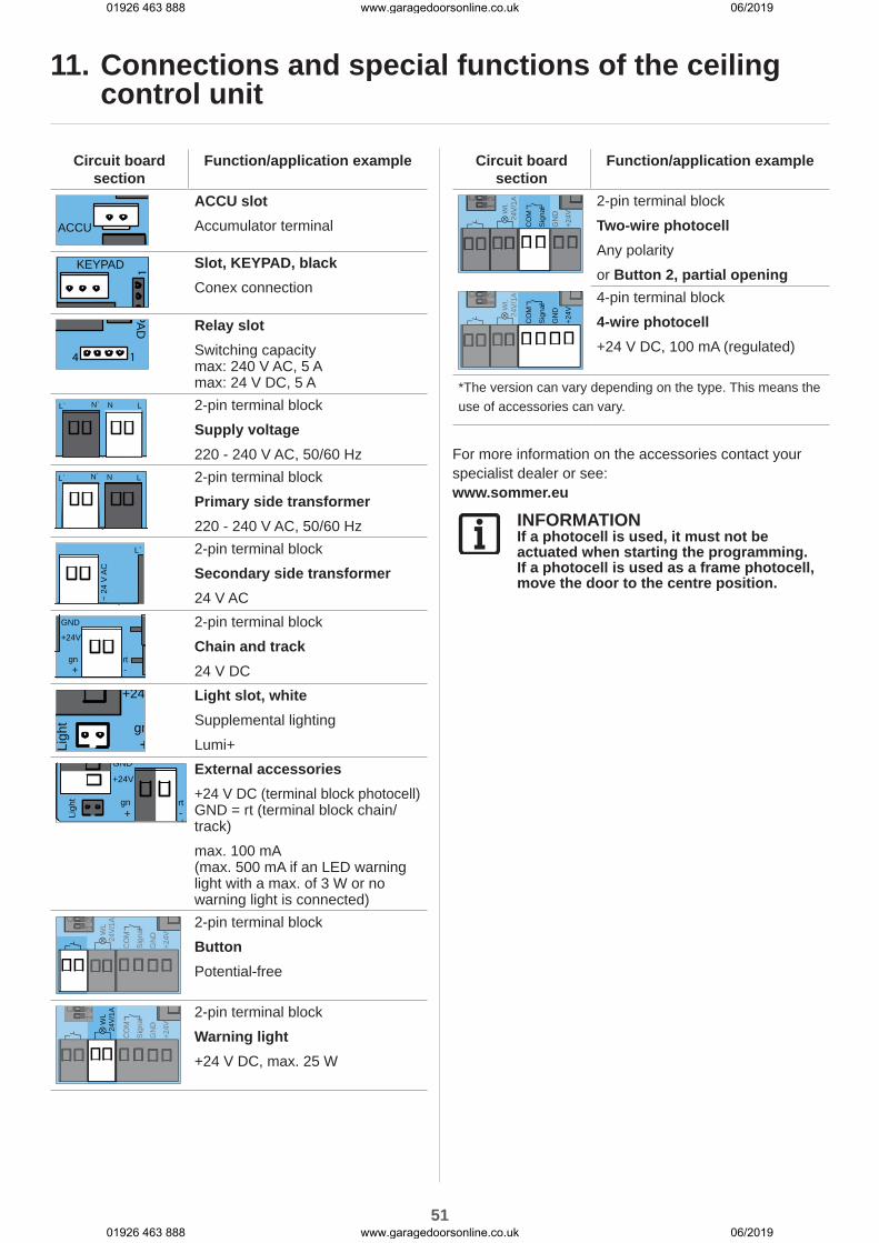
51
11. Connections and special functions of the ceiling control unit
Circuit board section
Function/application example
ACCU
ACCU slotAccumulator terminal
KEYPAD
1
Slot, KEYPAD, blackConex connection
PAD
14
Relay slotSwitching capacity max: 240 V AC, 5 A max: 24 V DC, 5 A
L` N` N L 2-pin terminal blockSupply voltage220 - 240 V AC, 50/60 Hz
L` N` N L 2-pin terminal blockPrimary side transformer220 - 240 V AC, 50/60 Hz
~ 2
4 V
AC
L` 2-pin terminal blockSecondary side transformer24 V AC
GND
+24V
gn rt+ -
2-pin terminal blockChain and track24 V DC
+24
Ligh
t gn+
Light slot, whiteSupplemental lightingLumi+
GND
+24V
Ligh
t gn rt+ -
External accessories+24 V DC (terminal block photocell) GND = rt (terminal block chain/track)max. 100 mA (max. 500 mA if an LED warning light with a max. of 3 W or no warning light is connected)
WL
24V
/1A
Sig
nal
CO
M
GN
D
+24V
O
12
WL
24V
/1A
Sig
nal
CO
M
GN
D
+24V
al12O
12 2-pin terminal block
ButtonPotential-free
WL
24V
/1A
Sig
nal
CO
M
GN
D
+24V
O
12O
12
Sig
nal
CO
M
GN
D
+24V
al12 2-pin terminal block
Warning light+24 V DC, max. 25 W
Circuit board section
Function/application example
WL
24V
/1A
Sig
nal
CO
M
GN
D
+24V
O
12
WL
24V
/1AO
12
GN
D
+24V
2-pin terminal blockTwo-wire photocellAny polarityor Button 2, partial opening
WL
24V
/1A
Sig
nal
CO
M
GN
D
+24V
O
12
WL
24V
/1AO
12 4-pin terminal block
4-wire photocell+24 V DC, 100 mA (regulated)
*The version can vary depending on the type. This means the use of accessories can vary.
For more information on the accessories contact your specialist dealer or see:www.sommer.eu
INFORMATIONIf a photocell is used, it must not be actuated when starting the programming.If a photocell is used as a frame photocell, move the door to the centre position.
01926 463 888 www.garagedoorsonline.co.uk 06/2019
01926 463 888 www.garagedoorsonline.co.uk 06/2019

52
11. Connections and special functions of the ceiling control unit
11.3 Setting the DIP switches on the ceiling control unit
Special functions can be set with the DIP switches on the ceiling control unit.All DIP switches are set to OFF by default.
NOTEDo not use a metal object to set the DIP switches, because this may damage the DIP switches or the circuit board.Use a suitable tool to set the DIP switches, such as a flat, thin plastic object.
DIP switches on the ceiling control unit ON OFF
1
ON
1 2 3 4
• "Conex" additional circuit board
• T1 defines door OPEN
• T2 defines door CLOSE
• "Conex" additional circuit board
• T1 pulse sequence
• T2 lighting function/partial opening
2
ON
1 2 3 4
• Relay (MUFU) trips during door movement and if the door is not closed*
• Relay (MUFU) lighting function
3
ON
1 2 3 4
• Continuous power to the complete system activated
• Power-saving mode activated
4
ON
1 2 3 4
• COM and Signal activated as button input (partial opening)
• COM and Signal activated as safety contact for photocell
* e.g.: door status display
11.4 Button 2 for partial openingIf required, another button can be connected for partial opening operation. After installation of the keypad, all settings must be made on the ceiling control unit and the motor carriage.
NOTEThe control unit cover is connected to the circuit board of the ceiling control unit via a connection cable. If an accumulator has been installed, it is also connected to the circuit board.Carefully remove the control unit cover and disconnect the connections to prevent damage to the ceiling control unit.
INFORMATIONIf button 2 (partial opening) is used, a photocell cannot be connected. The automatic closing operating mode is then not possible.
Installing the keypad
1. When installing the potential-free keypad, select a suitable position at a height of at least 1.6 m.
2. Install the keypad.
3. The keyboard cable for the ceiling control unit must be firmly secured to prevent displacement.
Installation of the control cable and settings on the ceiling control unit
1. Disconnect the operator from the mains voltage.Check that the operator is disconnected from the power supply.
2. Unscrew the cover from the ceiling control unit.
3. If an accumulator is used, it must also be disconnected, see Chapter "11.11 Installing and removing the accumulator".
4. Remove the control unit cover.
WL
24V
/1A
Sig
nal
CO
M
GN
D
+24V
O
12
WL
24V
/1AO
12
GN
D
+24V ON
1 2 3 4
Fig. 5 Fig. 6
01926 463 888 www.garagedoorsonline.co.uk 06/2019
01926 463 888 www.garagedoorsonline.co.uk 06/2019

53
11. Connections and special functions of the ceiling control unit
5. Connect the cable of button 2 to the terminal block for COM and Signal. ⇒ Button 2 is connected.
6. Set DIP switch 4 on the wall device to ON.
7. Plug in the connection cable for the button and for the accumulator, if necessary.
8. Close the ceiling control unit in reverse order, see Chapter "11.11 Installing and removing the accumulator" and "7.2 Cover of the ceiling control unit".
9. Supply the operator with the mains voltage.
Settings on the motor carriageTo determine the partial opening door position, the following settings must be made on the motor carriage.
1. Close the door completely up to the door CLOSE end position.
2. Open the motor carriage, see chapter "7.1 Cover of the motor carriage".
3. Set DIP switch 2 on the motor carriage to ON.
4. Press button 2 for the partial opening function. ⇒ The door moves in door OPEN direction.
5. Press button 2 again for the desired position for stopping. ⇒ The door stops at the desired position.
11.5 Deleting partial opening1. Set DIP switch 2 on the motor carriage to OFF.
2. Open the door completely up to the door OPEN end position. ⇒ Partial opening is deleted.
To program a new position, see Chapter "10.17 Setting partial opening".
11.6 Photocell and frame photocellA 2-wire photocell from SOMMER or a 4-wire photocell can be connected to the control unit. The control unit automatically detects which version it is and sets itself to that version.
Fig. Terminal for a 2-wire photocell
WL
24V
/1A
Sig
nal
CO
M
GN
D
+24V
O
12
WL
24V
/1AO
12
Fig. Terminal for a 4-wire photocell
INFORMATIONIf a photocell is retrofitted on a programmed system, the control unit must be reset, see Chapter "10.13 Resetting the control unit."
INFORMATIONIf a photocell is used, it must not be triggered when starting the programming.If a photocell is used as a frame photocell on the door, move the door to the centre position.
INFORMATIONDuring commissioning, the frame photocell must not be interrupted by persons or objects.
Frame photocell
1. Install the frame photocell in the frame, see separate "Frame photocell" installation instructions.
2. Align the frame photocell and connect to the ceiling control unit.
01926 463 888 www.garagedoorsonline.co.uk 06/2019
01926 463 888 www.garagedoorsonline.co.uk 06/2019

54
11. Connections and special functions of the ceiling control unit
3. Commissioning is performed as described in Chapter "9. Commissioning". ⇒ If the door passes the frame photocell, the illumination power of the operator lighting is reduced.If the illumination power is not reduced, the frame photocell must be realigned and the control unit must be reset.
⇒ During commissioning, the operator learns the exact position of the frame photocell in order to blank it out in normal mode shortly before reaching the door.
4. Check the frame photocell function.
11.7 Wall stationOther functions are available with the wall station. For example, a travel command can be executed, the lighting can be switched on or off or the operator can be locked. The selection of the locked areas can be changed via SOMlink. The connection features a polarity-protected 2-wire bus.The wall station is only supported by operators from 07/2017.
WL
24V
/1A
Sig
nal
CO
M
GN
D
+24V
O
12
WL
24V
/1A
Sig
nal
CO
M
GN
D
+24V
al12O
12
Fig. Button connection
INFORMATIONThe connection features a polarity-protected 2-wire bus.
Installing the wall stationSee the separate instructions for the "Wall station" for installation.
1. The following conditions must be met for installation of the wall station:
• a second separate access point• a suitable position with minimum height of 1.6 m.
2. Install the wall station.
3. The wall station cable for the ceiling control unit must be firmly secured to prevent displacement.
4. Connect the wall station to the button connection.
5. The power-saving mode must be deactivated. Set DIP switch 3 on the ceiling control unit to ON.
1
3
2
Fig. Wall station
Functions of the buttons• Opening, stopping and closing the door• Turning the lighting on and off• Locking or unlocking the operator
Opening, closing and stopping the door
1. Press the button (1) to open and close. ⇒ The door opens or closes depending on the starting position.
2. Press the button (1) during the opening or closing process. ⇒ The door stops:
3. Press the button (1) again. ⇒ The door moves into the respective starting position.
Turning the lighting on and offThe button (2) lights up green when the wall station is ready for operation and the operator is not locked.
1. Press the button (2). ⇒ Operator lighting switched on
2. Pressing the button (2) again switches the operator lighting back off. ⇒ Operator lighting off.
INFORMATIONIf the operator lighting is not switched off manually, it switches off automatically after 60 minutes. This value can be changed via SOMlink and a WiFi-enabled device.
The lighting cannot be switched off when the operator is moving.
Locking or unlocking the operatorUnauthorised access can be prevented by locking the operator. For example in the absence of the user
01926 463 888 www.garagedoorsonline.co.uk 06/2019
01926 463 888 www.garagedoorsonline.co.uk 06/2019

55
or to prevent unintentional activation with a handheld transmitter.The following functions are deactivated in the factory settings when the lock button is activated:
• Radio (handheld transmitter)• Senso ventilation function• Control device (corded external button)
To lock:The button (2) on the wall station lights up green when the operator is unlocked. The button (2) lights up red when the operator has been locked by the wall station.
1. Press and hold the button (3) for at least 5 seconds with the door closed. ⇒ Button (2) flashes green. ⇒ After 5 seconds, the button (2) lights up red. ⇒ Locking function activated. ⇒ All the functions of the operator are locked.
INFORMATIONIf the door was still open, it can be closed using the handheld transmitter. Only then are all operator functions locked.
To unlock:
1. Press the button (3) for at least 5 seconds. ⇒ Button (2) flashes red. ⇒ Button (2) lights up green. ⇒ Locking function deactivated. ⇒ All the functions of the operator are activated again.
INFORMATIONAll locking and unlocking functions can be modified and adjusted with SOMlink and a WiFi-enabled device. For more information ask your specialist dealer.
11.8 ConexTwo corded external buttons can be connected to the KEYPAD connection with the Conex accessory part. The function of the external buttons can be configured via DIP switch 1 of the ceiling control unit. The factory setting of DIP switch 1 is OFF.
KEYPAD
1
Fig. Keypad connectionThe Conex accessory part is plugged into the KEYPAD slot, see separate "Conex" instructions.
DIP switchesof the ceiling control unit ON OFF
1 ON
1 2 3 4
• "Conex" additional circuit board
• T1 defines door OPEN
• T2 defines door CLOSE
• "Conex" additional circuit board
• T1 pulse sequence
• T2 lighting function/partial opening
11.9 Output OCThe door status display can be shown with the Output OC (open collector output) accessory part. Set DIP switch 2 on the ceiling control unit to ON.
PAD
14
Fig. Relay slot for Output OCThe Output OC accessory part is plugged into the Relay slot, see separate "Output OC" instructions.
11. Connections and special functions of the ceiling control unit
01926 463 888 www.garagedoorsonline.co.uk 06/2019
01926 463 888 www.garagedoorsonline.co.uk 06/2019
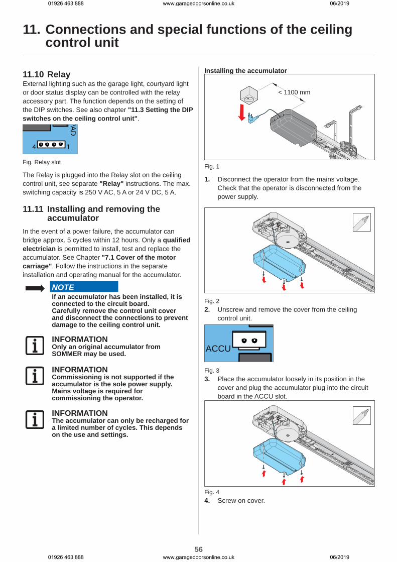
56
11.10 RelayExternal lighting such as the garage light, courtyard light or door status display can be controlled with the relay accessory part. The function depends on the setting of the DIP switches. See also chapter "11.3 Setting the DIP switches on the ceiling control unit".PA
D
14
Fig. Relay slot
The Relay is plugged into the Relay slot on the ceiling control unit, see separate "Relay" instructions. The max. switching capacity is 250 V AC, 5 A or 24 V DC, 5 A.
11.11 Installing and removing the accumulator
In the event of a power failure, the accumulator can bridge approx. 5 cycles within 12 hours. Only a qualified electrician is permitted to install, test and replace the accumulator. See Chapter "7.1 Cover of the motor carriage". Follow the instructions in the separate installation and operating manual for the accumulator.
NOTEIf an accumulator has been installed, it is connected to the circuit board.Carefully remove the control unit cover and disconnect the connections to prevent damage to the ceiling control unit.
INFORMATIONOnly an original accumulator from SOMMER may be used.
INFORMATIONCommissioning is not supported if the accumulator is the sole power supply.Mains voltage is required for commissioning the operator.
INFORMATIONThe accumulator can only be recharged for a limited number of cycles. This depends on the use and settings.
Installing the accumulator
< 1100 mm
Fig. 1
1. Disconnect the operator from the mains voltage.Check that the operator is disconnected from the power supply.
Fig. 22. Unscrew and remove the cover from the ceiling
control unit.
ACCU
Fig. 33. Place the accumulator loosely in its position in the
cover and plug the accumulator plug into the circuit board in the ACCU slot.
Fig. 44. Screw on cover.
11. Connections and special functions of the ceiling control unit
01926 463 888 www.garagedoorsonline.co.uk 06/2019
01926 463 888 www.garagedoorsonline.co.uk 06/2019

57
5. Attach the sticker "ACCU INSIDE" sticker to the outside of the housing in a highly visible place.
6. Run a function test. ⇒ Pull the power plug out of the power outlet. ⇒ The operator is powered by the accumulator.
7. Press the button on the handheld transmitter. ⇒ Operator opens or closes the door at reduced speed.
8. Connect the operator to the mains voltage.Check that the power supply is connected.
Removing the accumulatorThe accumulator is removed in the reverse order, see Chapter "11.11 Installing and removing the accumulator", section "Installing the accumulator".
DANGERDanger of hazardous substances!Improper storage, use or disposal of accumulators, batteries and operator components are dangerous for the health of humans and animals. Serious injury or death may result.
► Accumulators and batteries must be stored out of the reach of children and animals.
► Keep accumulators and batteries away from chemical, mechanical and thermal influences.
► Do not recharge old accumulators and batteries.
► Components of the operator as well as old accumulators and batteries must not be disposed of with household waste. They must be disposed of properly.
NOTEDispose of all components in accordance with local or national regulations to avoid environmental damage.
INFORMATIONAll operator components that have been taken out of service must not be disposed of with household waste, as they contain hazardous substances. The components must be disposed of correctly at an authorised recycling centre. The local and national regulations must be observed.
INFORMATIONOld batteries and battery packs must not be disposed of with household waste as they contain hazardous substances. These must be disposed of properly at municipal collection points or in containers provided by dealers. National guidelines must be observed.
11. Connections and special functions of the ceiling control unit
01926 463 888 www.garagedoorsonline.co.uk 06/2019
01926 463 888 www.garagedoorsonline.co.uk 06/2019
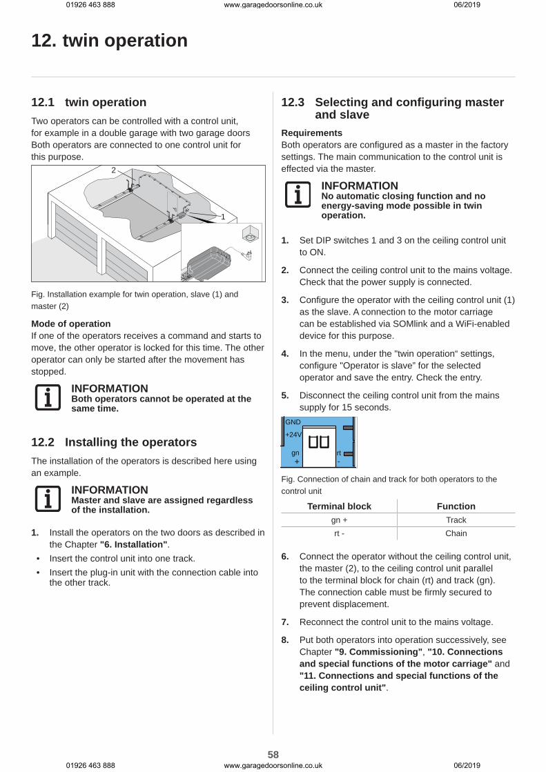
58
12. twin operation
12.1 twin operationTwo operators can be controlled with a control unit, for example in a double garage with two garage doors Both operators are connected to one control unit for this purpose.
2
1
Fig. Installation example for twin operation, slave (1) and master (2)
Mode of operationIf one of the operators receives a command and starts to move, the other operator is locked for this time. The other operator can only be started after the movement has stopped.
INFORMATIONBoth operators cannot be operated at the same time.
12.2 Installing the operatorsThe installation of the operators is described here using an example.
INFORMATIONMaster and slave are assigned regardless of the installation.
1. Install the operators on the two doors as described in the Chapter "6. Installation".
• Insert the control unit into one track.• Insert the plug-in unit with the connection cable into
the other track.
12.3 Selecting and configuring master and slave
RequirementsBoth operators are configured as a master in the factory settings. The main communication to the control unit is effected via the master.
INFORMATIONNo automatic closing function and no energy-saving mode possible in twin operation.
1. Set DIP switches 1 and 3 on the ceiling control unit to ON.
2. Connect the ceiling control unit to the mains voltage. Check that the power supply is connected.
3. Configure the operator with the ceiling control unit (1) as the slave. A connection to the motor carriage can be established via SOMlink and a WiFi-enabled device for this purpose.
4. In the menu, under the "twin operation“ settings, configure "Operator is slave” for the selected operator and save the entry. Check the entry.
5. Disconnect the ceiling control unit from the mains supply for 15 seconds.
GND
+24V
gn rt+ -
Fig. Connection of chain and track for both operators to the control unit
Terminal block Functiongn + Trackrt - Chain
6. Connect the operator without the ceiling control unit, the master (2), to the ceiling control unit parallel to the terminal block for chain (rt) and track (gn). The connection cable must be firmly secured to prevent displacement.
7. Reconnect the control unit to the mains voltage.
8. Put both operators into operation successively, see Chapter "9. Commissioning", "10. Connections and special functions of the motor carriage" and "11. Connections and special functions of the ceiling control unit".
01926 463 888 www.garagedoorsonline.co.uk 06/2019
01926 463 888 www.garagedoorsonline.co.uk 06/2019

59
12. twin operation
9. Programme the handheld transmitters for the respective operators, see Chapter "10.4 Explanation of the radio channels" and "10.5 Programming the transmitter".
INFORMATIONOnly one handheld transmitter can be assigned per function. Undesired malfunctions could otherwise occur.
12.4 Partial openingOne partial opening can be programmed for each of the two operators (master and slave). Programming or deletion is performed as for the standard equipment, see Chapter "10.17 Setting partial opening" and "10.18 Deleting partial opening".
Example:Master on radio channel CH 2 (partial opening) on handheld transmitter button 3. For the slave, on radio channel CH 2 (partial opening) on handheld transmitter button 4.
WiredThe COM input and signal on the ceiling control unit can be used for this purpose. DIP switch 4 on the ceiling control unit must be ON.The input is then no longer available for connection of a photocell.
Mode of operationIf button 2 (partial opening) is activated, the master receives the partial opening command. See also chapter "10.17 Setting partial opening".
12.5 Defined opening and closingThe functions Defined opening and closing of the operators (master and slave) can only be configured via the CH 3 and CH 4 radio channels. These settings are not available when corded or via the Conex accessory part.
12.6 Door status displayIf DIP switch 2 on the ceiling control unit is set to ON, the relay is activated during door movement and when the door is open. It remains activated until both operators (master and slave) are again at the door CLOSE end position.
12.7 Lighting for twin operationThe lighting can be switched on and off for the selected operator via the respective handheld transmitter. This also applies for the connected supplemental lighting, see also Chapter "10.16 Setting the lighting function".
12.8 PhotocellOptionally, a photocell can be connected. The photocell must be configured in such a way that it can be aligned to cover two doors. If the photocell is interrupted, the operator of the moving door reverses. See also chapter "11.6 Photocell and frame photocell".
INFORMATIONIf a photocell is retrofitted on a programmed system, the control unit must be reset, see Chapter "10.13 Resetting the control unit."
12.9 External buttonWith the Conex additional circuit board, both operators (master and slave) can be operated in pulse sequence mode. Fit the Conex as described in the separate instructions. Set DIP switch 1 on the ceiling control unit to ON.
Mode of operationButton 1 - masterButton 2 - slave
12.10 ResetThe slave becomes the master again when a factory reset is carried out. The operator must be configured as the slave again via SOMlink and a WiFi-enabled device, see Chapter "12.3 Selecting and configuring master and slave".
01926 463 888 www.garagedoorsonline.co.uk 06/2019
01926 463 888 www.garagedoorsonline.co.uk 06/2019
60
13. Function test and final test
13.1 Testing obstacle detectionObserve in particular the following safety instructions for this chapter.After commissioning the operator, the force measurement of the operator must be checked with a force measurement device and an obstacle detection test must be performed.
WARNINGDanger due to projecting parts!Gate leaves or other parts must not project into public roads or footpaths. This also applies while the door is moving.This may cause serious injury or death to persons or animals.
► Keep public roads and footpaths clear of projecting parts.
WARNINGDanger of entrapment!If the force setting is too high, persons or animals in the movement area of the door may be trapped and pulled along with the door. Severe injuries or death may result.
► The force setting is relevant to safety and must be carried out by a trained specialist.
► You must proceed with extreme caution if you check and if necessary adjust the force setting.
WARNINGDanger of crushing and shearing!If the door moves and there are persons or animals in the movement area, crushing and shearing injuries may be caused by the mechanism and safety edges of the door.
► Note that obstacle detection does not operate below 50 mm.
► The obstacle detection must be tested once a month.
► Only use the operator when you have a direct view of the door.
► All danger zones must be visible during the entire door operation.
► Always keep the moving door in sight. ► Keep persons and animals clear of the range of movement of the door.
► Never put your hand near the door when it is moving or near moving parts. In particular, do not reach into the moving push arm.
► Do not reach into the ceiling suspension unit when the motor carriage is running along the track.
► Do not drive through the door until it has opened completely.
► Never stand under the opened door.
NOTEObserve the national standards, guidelines and regulations for cut-off of the operating forces.
NOTEThe obstacle detection must be tested once a month to prevent damage to the operator.
01926 463 888 www.garagedoorsonline.co.uk 06/2019
01926 463 888 www.garagedoorsonline.co.uk 06/2019
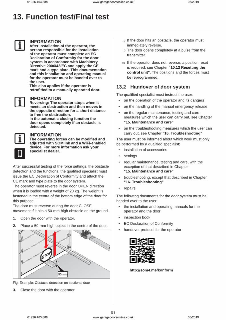
61
13. Function test/Final test
INFORMATIONAfter installation of the operator, the person responsible for the installation of the operator must complete an EC Declaration of Conformity for the door system in accordance with Machinery Directive 2006/42/EC and apply the CE mark and a type plate. This documentation and this installation and operating manual for the operator must be handed over to the user.This also applies if the operator is retrofitted to a manually operated door.
INFORMATIONReversing: The operator stops when it meets an obstruction and then moves in the opposite direction for a short distance to free the obstruction.In the automatic closing function the door opens completely if an obstacle is detected.
INFORMATIONThe operating forces can be modified and adjusted with SOMlink and a WiFi-enabled device. For more information ask your specialist dealer.
After successful testing of the force settings, the obstacle detection and the functions, the qualified specialist must issue the EC Declaration of Conformity and attach the CE mark and type plate to the door system.The operator must reverse in the door OPEN direction when it is loaded with a weight of 20 kg. The weight is fastened in the centre of the bottom edge of the door for this purpose.The door must reverse during the door CLOSE movement if it hits a 50-mm-high obstacle on the ground.
1. Open the door with the operator.
2. Place a 50-mm-high object in the centre of the door.
50 mm
Fig. Example: Obstacle detection on sectional door
3. Close the door with the operator.
⇒ If the door hits an obstacle, the operator must immediately reverse.
⇒ The door opens completely at a pulse from the transmitter.
⇒ If the operator does not reverse, a position reset is required, see Chapter "10.13 Resetting the control unit". The positions and the forces must be reprogrammed.
13.2 Handover of door systemThe qualified specialist must instruct the user:
• on the operation of the operator and its dangers• on the handling of the manual emergency release• on the regular maintenance, testing and care
measures which the user can carry out, see Chapter "15. Maintenance and care"
• on the troubleshooting measures which the user can carry out, see Chapter "16. Troubleshooting"
The user must be informed about which work must only be performed by a qualified specialist:
• installation of accessories• settings• regular maintenance, testing and care, with the
exception of that described in Chapter "15. Maintenance and care"
• troubleshooting, except that described in Chapter "16. Troubleshooting"
• repairs
The following documents for the door system must be handed over to the user:
• the installation and operating manuals for the operator and the door
• inspection book• EC Declaration of Conformity• handover protocol for the operator
http://som4.me/konform
01926 463 888 www.garagedoorsonline.co.uk 06/2019
01926 463 888 www.garagedoorsonline.co.uk 06/2019

62
14. Operation
14.1 Safety information on operationIn particular, observe the following safety instructions and the safety instructions in Chapters "15. Maintenance and care" and "16. Troubleshooting".The operator must not be used by persons with restricted physical, sensory or mental capacity or who lack experience and knowledge. All users must be specially instructed and have read and understood the installation and operating instructions.Children must never play with or use the operator, even under supervision. Children must be kept clear of the operator. Handheld transmitters or other control devices must never be given to children. Handheld transmitters must be safely stored and protected against unintended and unauthorised use.
DANGERDanger if not observed!If safety instructions are not observed, serious injury or death may result.
► All safety instructions must be complied with.
DANGERDanger due to use of the operator with incorrect setting or when it is in need of repair!If the operator is used despite incorrect settings or if it is in need of repair, severe injury or death may result.
► The operator may only be used with the required settings and in the proper condition.
► You must have faults repaired professionally without delay.
WARNINGDanger due to falling parts of doors!Actuating the emergency release can lead to uncontrolled door movement if
• springs are weakened or broken.• the door has not been optimally
weight-balanced.Falling parts may cause a hazard. Severe injuries or death may result.
► Check the weight balance of the door at regular intervals.
► Pay attention to the movement of the door when the emergency release is actuated.
► Keep clear of the movement area of the door.
WARNINGDanger of entrapment!Persons and animals in the movement area of the door may be trapped and pulled along with the door. Severe injuries or death may result.
► Keep clear of the moving door.
01926 463 888 www.garagedoorsonline.co.uk 06/2019
01926 463 888 www.garagedoorsonline.co.uk 06/2019

63
14. Operation
NOTEObjects in the movement area of the door may be jammed and damaged.Objects must not be in the range of movement of the door.
INFORMATIONKeep this installation and operating manual accessible to all users at the place of use.
14.2 Handover to the userThe user must ensure that the CE mark and the type plate have been attached to the door system.The following documents for the door system must be handed over to the user:
• the installation and operating manuals for the operator and the door
• inspection book• EC Declaration of Conformity• handover protocol
The qualified specialist must instruct the user:• on the operation of the operator and its dangers• on the handling of the manual emergency release• on regular maintenance, testing and care which the
user can carry out
The user must be informed about which work must only be performed by a qualified specialist:
• installation of accessories• settings• regular maintenance, testing and care which can
be carried out by the user, except that described in Chapter "15. Maintenance and care"
• Troubleshooting measures which can be carried out by the user, except those described in Chapter "16. Troubleshooting"
The user is responsible for:• the intended use of the operator• its good condition• operation• instructing all users how to use the door system and
in the associated hazards• the handling of the manual emergency release• maintenance, testing and care• tests by a qualified specialist• troubleshooting in case of faults by a qualified
specialist
WARNINGDanger of crushing and shearing!If the door moves and there are persons or animals in the movement area, crushing and shearing injuries may be caused by the mechanism and safety edges of the door.
► Only use the operator when you have a direct view of the door.
► All danger zones must be visible during the entire door operation.
► Always keep the moving door in sight. ► Keep persons and animals clear of the range of movement of the door.
► Never put your hand near the door when it is moving or near moving parts. In particular, do not reach into the moving push arm.
► Do not reach into the ceiling suspension unit when the motor carriage is running along the track.
► Do not drive through the door until it has opened completely.
► Never stand under the opened door.
WARNINGDanger due to optical radiation!Looking into an LED at short range for an extended period may cause optical glare. This may temporarily reduce vision. This may cause serious or fatal accidents.
► Never look directly into an LED.
NOTEIf the weight compensation of the door is incorrectly adjusted, the operator may be damaged.
• The door must be stable.• It must not bend, rotate or twist when
opening and closing.• The door must move easily in its tracks.
Defects must be repaired without delay by a qualified specialist.
01926 463 888 www.garagedoorsonline.co.uk 06/2019
01926 463 888 www.garagedoorsonline.co.uk 06/2019

64
14. Operation
The user must keep this installation and operating manual ready for consultation in the vicinity of the door system at all times.
14.3 Operating modes of door movement
WARNINGDanger of crushing and shearing!The door can be actuated by a keypad or another control device.Persons who cannot see the door and are in the range of movement of the mechanism or the closing edges may be injured by crushing or shearing.
► Keypads or other control devices may be used only if the movement of the door can be viewed directly.
► Keep persons and animals clear of the range of movement of the door.
► Never stand under the opened door.
INFORMATIONAll functions can be programmed for all buttons.
Button 1 (CH 1)
STOP STOP
Fig. Pulse sequence door OPEN, door stop, door CLOSE, door stop
Button 2 (CH 2)
Fig. Pulse sequence forpartial opening: DIP switch 2 ONLighting function: DIP switch 2 OFF
Button 3 (CH 3)
STOP
Fig. Pulse sequence for defined door OPEN
Button 4 (CH 4)
STOP
Fig. Pulse sequence for defined door CLOSE
01926 463 888 www.garagedoorsonline.co.uk 06/2019
01926 463 888 www.garagedoorsonline.co.uk 06/2019
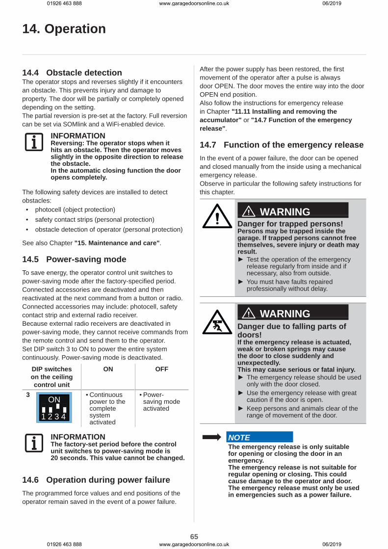
65
14. Operation
14.4 Obstacle detectionThe operator stops and reverses slightly if it encounters an obstacle. This prevents injury and damage to property. The door will be partially or completely opened depending on the setting.The partial reversion is pre-set at the factory. Full reversion can be set via SOMlink and a WiFi-enabled device.
INFORMATIONReversing: The operator stops when it hits an obstacle. Then the operator moves slightly in the opposite direction to release the obstacle.In the automatic closing function the door opens completely.
The following safety devices are installed to detect obstacles:
• photocell (object protection)• safety contact strips (personal protection)• obstacle detection of operator (personal protection)
See also Chapter "15. Maintenance and care".
14.5 Power-saving modeTo save energy, the operator control unit switches to power-saving mode after the factory-specified period. Connected accessories are deactivated and then reactivated at the next command from a button or radio.Connected accessories may include: photocell, safety contact strip and external radio receiver.Because external radio receivers are deactivated in power-saving mode, they cannot receive commands from the remote control and send them to the operator.Set DIP switch 3 to ON to power the entire system continuously. Power-saving mode is deactivated.
DIP switches on the ceiling control unit
ON OFF
3 ON
1 2 3 4
• Continuous power to the complete system activated
• Power-saving mode activated
INFORMATIONThe factory-set period before the control unit switches to power-saving mode is 20 seconds. This value cannot be changed.
14.6 Operation during power failureThe programmed force values and end positions of the operator remain saved in the event of a power failure.
After the power supply has been restored, the first movement of the operator after a pulse is always door OPEN. The door moves the entire way into the door OPEN end position.Also follow the instructions for emergency release in Chapter "11.11 Installing and removing the accumulator" or "14.7 Function of the emergency release".
14.7 Function of the emergency releaseIn the event of a power failure, the door can be opened and closed manually from the inside using a mechanical emergency release.Observe in particular the following safety instructions for this chapter.
WARNINGDanger for trapped persons!Persons may be trapped inside the garage. If trapped persons cannot free themselves, severe injury or death may result.
► Test the operation of the emergency release regularly from inside and if necessary, also from outside.
► You must have faults repaired professionally without delay.
WARNINGDanger due to falling parts of doors!If the emergency release is actuated, weak or broken springs may cause the door to close suddenly and unexpectedly.This may cause serious or fatal injury.
► The emergency release should be used only with the door closed.
► Use the emergency release with great caution if the door is open.
► Keep persons and animals clear of the range of movement of the door.
NOTEThe emergency release is only suitable for opening or closing the door in an emergency.The emergency release is not suitable for regular opening or closing. This could cause damage to the operator and door. The emergency release must only be used in emergencies such as a power failure.
01926 463 888 www.garagedoorsonline.co.uk 06/2019
01926 463 888 www.garagedoorsonline.co.uk 06/2019

66
NOTEIn an emergency release, the door could open or close by itself surprisingly quickly due to a broken spring or incorrect setting of the weight balancing.Damage to the door system could occur.
NOTEAfter the operator is locked back in, move the door into the door OPEN end position. Otherwise the guide idler will be hit with too much force.
NOTEObjects in the movement area of the door may be jammed and damaged.Objects must not be in the range of movement of the door.
INFORMATIONIt can be locked and released in any door position.
1. Disconnect the operator from the mains voltage.Check it is disconnected from the power supply.
“clic”
Fig. 1 Fig. 2
2. Pull once on the emergency release cord.
⇒ The motor carriage is released. ⇒ Door can be moved by hand.
14. Operation
3. Pull the emergency release cord once more.
⇒ The motor carriage is locked. ⇒ The door can only be moved by the operator.
4. Connect the operator to the mains voltage. Check that the power supply is connected.
5. Give the operator a command. ⇒ After a power failure, the first pulse of the operator is always in the door OPEN direction.
⇒ The operator must drive completely to the door OPEN end position.
01926 463 888 www.garagedoorsonline.co.uk 06/2019
01926 463 888 www.garagedoorsonline.co.uk 06/2019
67
15. Maintenance and care
15.1 Safety instructions for maintenance and care
Follow the basic safety instructions listed below.Service the operator regularly as directed below. This ensures safe operation and a long service life of your operator.
DANGERDanger if not observed!If safety instructions are not observed, serious injury or death may result.
► All safety instructions must be complied with.
DANGERDanger due to electric current!Contact with live parts may result in electric current flowing through the body. Electric shock, burns or death may result.
► All work on electrical components may only be carried out by a trained electrician.
► Disconnect the mains plug before working on the operator.
► If an accumulator is connected, disconnect it from the control unit.
► Check that the operator is not live. ► Secure the operator against being switched back on.
WARNINGDanger of falling!Unsafe or defective ladders may tip and cause fatal or serious accidents.
► Use only a non-slip, stable ladder. ► Ensure that ladders are safely positioned.
WARNINGDanger for trapped persons!Persons may be trapped inside the garage. If trapped persons cannot free themselves, severe injury or death may result.
► Test the operation of the emergency release regularly from inside and if necessary, also from outside.
► You must have faults repaired professionally without delay.
WARNINGDanger due to falling parts of doors!Parts of the door may become detached and fall. If persons or animals are hit, this may cause serious injury or death.
► Always keep the moving door in sight. ► Keep all persons and animals away from the door until it is completely opened or closed.
WARNINGDanger of crushing and shearing!If the door moves and there are persons or animals in the movement area, crushing and shearing injuries may be caused by the mechanism and safety edges of the door.
► Only use the operator when you have a direct view of the door.
► All danger zones must be visible during the entire door operation.
► Always keep the moving door in sight. ► Keep persons and animals clear of the range of movement of the door.
► Never put your hand near the door when it is moving or near moving parts. In particular, do not reach into the moving push arm.
► Do not reach into the ceiling suspension unit when the motor carriage is running along the track.
► Do not drive through the door until it has opened completely.
► Never stand under the opened door.
01926 463 888 www.garagedoorsonline.co.uk 06/2019
01926 463 888 www.garagedoorsonline.co.uk 06/2019

68
15. Maintenance and care
WARNINGDanger due to hot surfaces!After frequent operation parts of the motor carriage or the control unit may become hot. If the cover is removed and hot parts are touched, they may cause burns.
► Allow the operator to cool down before removing the cover.
NOTEThe motor carriage is supplied with safety low voltage via the chain and the track.The use of oil or grease will greatly reduce the conductivity of the chain, track and motor carriage. This may result in faults due to inadequate electrical contact.The chain and track are maintenance-free and must not be oiled or greased.
NOTEThe use of unsuitable cleaning agents may damage the surface of the operator.Clean the operator with a dry lint-free cloth only.
15.2 Maintenance scheduleHow
often? What? How?
Once a month
• Test the emergency release
• See Chapter "14.7 Function of the emergency release"
• Test obstacle detection
• See Chapter "13.1 Testing obstacle detection"
• Test photocell
• Interrupt the active photocell while the door is closing. The door must stop and open slightly. If automatic closing is activated, the door opens completely.
• If necessary, clean the photocell, see Chapter "15.3 Care"
Once a year
• Test the door and all moving parts
• As directed by the door manufacturer
• Check screws on door, ceiling or lintel
• Check that screws are tight and tighten if necessary
As needed
• Chain and track • Maintenance-free
• Track • See Chapter• "15.3 Care"
• Clean the housing of the ceiling control unit and motor carriage
• See Chapter• "15.3 Care"
01926 463 888 www.garagedoorsonline.co.uk 06/2019
01926 463 888 www.garagedoorsonline.co.uk 06/2019
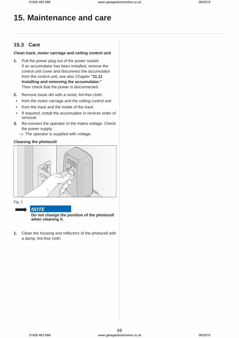
69
15. Maintenance and care
15.3 CareClean track, motor carriage and ceiling control unit
1. Pull the power plug out of the power socket.If an accumulator has been installed, remove the control unit cover and disconnect the accumulator from the control unit, see also Chapter "11.11 Installing and removing the accumulator."Then check that the power is disconnected.
2. Remove loose dirt with a moist, lint-free cloth:• from the motor carriage and the ceiling control unit• from the track and the inside of the track• If required, install the accumulator in reverse order of
removal.3. Re-connect the operator to the mains voltage. Check
the power supply. ⇒ The operator is supplied with voltage.
Cleaning the photocell
Fig. 1
NOTEDo not change the position of the photocell when cleaning it.
1. Clean the housing and reflectors of the photocell with a damp, lint-free cloth.
01926 463 888 www.garagedoorsonline.co.uk 06/2019
01926 463 888 www.garagedoorsonline.co.uk 06/2019

70
16. Troubleshooting
16.1 Safety instructions for troubleshooting
Follow the basic safety instructions listed below.
DANGERDanger if not observed!If safety instructions are not observed, serious injury or death may result.
► All safety instructions must be complied with.
DANGERDanger due to electric current!Contact with live parts may result in electric current flowing through the body. Electrical shock, burns, or death may result.
► All work on electrical components may only be carried out by a trained electrician.
► Disconnect the mains plug before working on the operator.
► If an accumulator is connected, disconnect it from the control unit.
► Check that the operator is not live. ► Secure the operator against being switched back on.
WARNINGDanger of falling!Unsafe or defective ladders may tip and cause serious or fatal accidents.
► Use only a non-slip, stable ladder. ► Ensure that ladders are safely positioned.
WARNINGDanger for trapped persons!Persons may be trapped inside the garage. If trapped persons cannot free themselves, severe injury or death may result.
► Test the operation of the emergency release regularly from inside and if necessary, also from outside.
► You must have faults repaired professionally without delay.
WARNINGDanger due to falling parts!Parts of the door may become detached and fall. Persons may be hit. Severe injuries or death may result.
► Always keep the moving door in sight. ► Keep all persons and animals away from the door until it is completely opened or closed.
► Do not drive through the door until it has opened completely.
WARNINGDanger of entrapment!Loose clothing or long hair may be trapped by moving parts of the door.
► Keep clear of the moving door. ► Always wear tight-fitting clothing. ► Wear a hairnet if you have long hair.
01926 463 888 www.garagedoorsonline.co.uk 06/2019
01926 463 888 www.garagedoorsonline.co.uk 06/2019
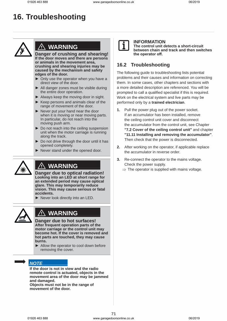
71
WARNINGDanger of crushing and shearing!If the door moves and there are persons or animals in the movement area, crushing and shearing injuries may be caused by the mechanism and safety edges of the door.
► Only use the operator when you have a direct view of the door.
► All danger zones must be visible during the entire door operation.
► Always keep the moving door in sight. ► Keep persons and animals clear of the range of movement of the door.
► Never put your hand near the door when it is moving or near moving parts. In particular, do not reach into the moving push arm.
► Do not reach into the ceiling suspension unit when the motor carriage is running along the track.
► Do not drive through the door until it has opened completely.
► Never stand under the opened door.
WARNINGDanger due to optical radiation!Looking into an LED at short range for an extended period may cause optical glare. This may temporarily reduce vision. This may cause serious or fatal accidents.
► Never look directly into an LED.
WARNINGDanger due to hot surfaces!After frequent operation parts of the motor carriage or the control unit may become hot. If the cover is removed and hot parts are touched, they may cause burns.
► Allow the operator to cool down before removing the cover.
NOTEIf the door is not in view and the radio remote control is actuated, objects in the movement area of the door may be jammed and damaged.Objects must not be in the range of movement of the door.
INFORMATIONThe control unit detects a short-circuit between chain and track and then switches the operator off.
16.2 TroubleshootingThe following guide to troubleshooting lists potential problems and their causes and information on correcting them. In some cases, other chapters and sections with a more detailed description are referenced. You will be prompted to call a qualified specialist if this is required.Work on the electrical system and live parts may be performed only by a trained electrician.
1. Pull the power plug out of the power socket.If an accumulator has been installed, remove the ceiling control unit cover and disconnect the accumulator from the control unit, see Chapter "7.2 Cover of the ceiling control unit" and chapter "11.11 Installing and removing the accumulator".Then check that the power is disconnected.
2. After working on the operator, if applicable replace the accumulator in reverse order.
3. Re-connect the operator to the mains voltage. Check the power supply. ⇒ The operator is supplied with mains voltage.
16. Troubleshooting
01926 463 888 www.garagedoorsonline.co.uk 06/2019
01926 463 888 www.garagedoorsonline.co.uk 06/2019
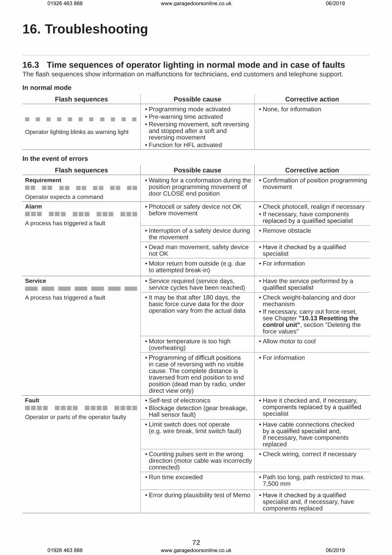
72
16.3 Time sequences of operator lighting in normal mode and in case of faultsThe flash sequences show information on malfunctions for technicians, end customers and telephone support.
In normal modeFlash sequences Possible cause Corrective action
Operator lighting blinks as warning light
• Programming mode activated• Pre-warning time activated• Reversing movement, soft reversing
and stopped after a soft and reversing movement
• Function for HFL activated
• None, for information
In the event of errorsFlash sequences Possible cause Corrective action
Requirement
Operator expects a command
• Waiting for a conformation during the position programming movement of door CLOSE end position
• Confirmation of position programming movement
Alarm
A process has triggered a fault
• Photocell or safety device not OK before movement
• Check photocell, realign if necessary• If necessary, have components replaced by a qualified specialist
• Interruption of a safety device during the movement
• Remove obstacle
• Dead man movement, safety device not OK
• Have it checked by a qualified specialist
• Motor return from outside (e.g. due to attempted break-in)
• For information
Service
A process has triggered a fault
• Service required (service days, service cycles have been reached)
• Have the service performed by a qualified specialist
• It may be that after 180 days, the basic force curve data for the door operation vary from the actual data
• Check weight-balancing and door mechanism
• If necessary, carry out force reset, see Chapter "10.13 Resetting the control unit", section "Deleting the force values"
• Motor temperature is too high (overheating)
• Allow motor to cool
• Programming of difficult positions in case of reversing with no visible cause. The complete distance is traversed from end position to end position (dead man by radio, under direct view only)
• For information
Fault
Operator or parts of the operator faulty
• Self-test of electronics• Blockage detection (gear breakage,
Hall sensor fault)
• Have it checked and, if necessary, components replaced by a qualified specialist
• Limit switch does not operate (e.g. wire break, limit switch fault)
• Have cable connections checked by a qualified specialist and, if necessary, have components replaced
• Counting pulses sent in the wrong direction (motor cable was incorrectly connected)
• Check wiring, correct if necessary
• Run time exceeded • Path too long, path restricted to max. 7,500 mm
• Error during plausibility test of Memo • Have it checked by a qualified specialist and, if necessary, have components replaced
16. Troubleshooting
01926 463 888 www.garagedoorsonline.co.uk 06/2019
01926 463 888 www.garagedoorsonline.co.uk 06/2019

73
16. Troubleshooting
16.4 Troubleshooting table
Problem Possible cause Test/check RemedyThe operator opens the door when the transmitter or control device is actuated but does not close it.
• Photocell and safety device interrupted
• Check photocell and safety devices
• Remove obstacle• The photocell must be aligned• Have it checked and replaced by a qualified specialist
• Automatic closing function activated
• Wait to see whether the operator starts automatically after 30 seconds
• Automatic closing function deactivated
• Have the cause corrected by a trained electrician
Operator cannot be operated with the control device.
• No power • Check power supply • Check the power socket with a different device, for example by plugging in a lamp
• Limit switch on motor carriage defective
• Unlock operator and push motor carriage to the centre of the track
• Lock operator• Actuate transmitter• If the operator still closes the
door but does not open it, the limit switch is defective
• Have the limit switch replaced by a qualified specialist
• The operator was unlocked by the emergency release mechanism
• Check that the door can be moved manually
• Pull the emergency release handle to lock the operator
• Control device incorrectly connected to the operator
• Check function of operator with a transmitter
• Check wiring, correct if necessary
• Transmitter defective • Operator cannot be started with the transmitter
• Check transmitter power supply• If necessary, replace the battery of
the transmitter• If necessary, replace the
transmitter with a new one• Operator defective • Operator cannot be started
with the transmitter or the connected control device
• Have operator repaired or replaced by a qualified specialist
• Electrical supply voltage outside the approved range
• Have the mains voltage checked by a trained electrician
• Have the cause corrected by a trained electrician
When a button on the transmitter is pressed, the door does not open or close.
• Transmitter not programmed
• Radio LED does not light up when the transmitter is operated
• Programme transmitter
• Battery in the transmitter is flat
• Replace the battery of the transmitter
• Transmitter defective • LED on transmitter does not light up
• Replace transmitter
Radio command cannot be programmed.
• Memory full • All four LEDs for radio blink cyclically for about 3 seconds
• Memory full, see Chapter "10.6 Information on Memo" and "10.8 Deleting a transmitter button from the radio channel"
MEMO Identifier error • Incorrect MEMO • All four LEDs blink cyclically for a short time and then go out for a long time. The operator lighting of the motor carriage blinks 4 times short and 4 times long.
• Disconnect operator from the power supply, unplug Memo, re-supply operator with power
MEMO device type error
• System error • All four LEDs blink cyclically for a long time and then go out for a short time. If voltage is present, the operator lighting of the motor carriage blinks an additional four times.
• Memo can be deleted via the Radio button, see Chapter "10.8 Deleting a transmitter button from the radio channel"
01926 463 888 www.garagedoorsonline.co.uk 06/2019
01926 463 888 www.garagedoorsonline.co.uk 06/2019
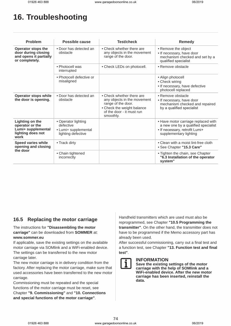
74
Problem Possible cause Test/check RemedyOperator stops the door during closing and opens it partially or completely.
• Door has detected an obstacle
• Check whether there are any objects in the movement range of the door.
• Remove the object• If necessary, have door
mechanism checked and set by a qualified specialist
• Photocell was interrupted
• Check LEDs on photocell. • Remove obstacle
• Photocell defective or misaligned
• Align photocell• Check wiring• If necessary, have defective
photocell replacedOperator stops while the door is opening.
• Door has detected an obstacle
• Check whether there are any objects in the movement range of the door.
• Check the weight balance of the door - it must run smoothly.
• Remove obstacle• If necessary, have door
mechanism checked and repaired by a qualified specialist
Lighting on the operator or the Lumi+ supplemental lighting does not work
• Operator lighting defective
• Lumi+ supplemental lighting defective
• Have motor carriage replaced with a new one by a qualified specialist
• If necessary, retrofit Lumi+ supplementary lighting
Speed varies while opening and closing the door
• Track dirty • Clean with a moist lint-free cloth• See Chapter "15.3 Care"
• Chain tightened incorrectly
• Tighten the chain, see Chapter "6.3 Installation of the operator system"
16. Troubleshooting
16.5 Replacing the motor carriageThe instructions for "Disassembling the motor carriage" can be downloaded from SOMMER at:www.sommer.euIf applicable, save the existing settings on the available motor carriage via SOMlink and a WiFi-enabled device. The settings can be transferred to the new motor carriage later.The new motor carriage is in delivery condition from the factory. After replacing the motor carriage, make sure that used accessories have been transferred to the new motor carriage.Commissioning must be repeated and the special functions of the motor carriage must be reset, see Chapter "9. Commissioning" and "10. Connections and special functions of the motor carriage".
Handheld transmitters which are used must also be reprogrammed, see Chapter "10.5 Programming the transmitter". On the other hand, the transmitter does not have to be programmed if the Memo accessory part has already been used.After successful commissioning, carry out a final test and a function test, see Chapter "13. Function test and final test".
INFORMATIONSave the existing settings of the motor carriage with the help of SOMlink and a WiFi-enabled device. After the new motor carriage has been inserted, reinstall the data.
01926 463 888 www.garagedoorsonline.co.uk 06/2019
01926 463 888 www.garagedoorsonline.co.uk 06/2019

75
17. Taking out of operation, storage and disposal
17.1 Taking the operator out of operation and disassembly
Follow the basic safety instructions listed below.People under the influence of drugs, alcohol, or medications that can influence their ability to react may not work on the operator.The disassembly and disposal of the operator may only be performed by a qualified specialist.This installation and operating manual must be read, understood and complied with by the qualified specialist who disassembles the operator.
DANGERDanger if not observed!If safety instructions are not observed, serious injury or death may result.
► All safety instructions must be complied with.
DANGERDanger due to electric current!Contact with live parts may result in electric current flowing through the body. Electric shock, burns or death will result.
► All disassembly work on electrical components may only be carried out by a trained electrician.
► Disconnect the power plug before disassembling the operator.
► If an accumulator is connected, disconnect it from the control unit.
► Check that the operator is not live. ► Secure the operator against being switched back on.
WARNINGDanger of falling!Unsafe or defective ladders may tip and cause serious or fatal accidents.
► Use only a non-slip, stable ladder. ► Ensure that ladders are safely positioned.
WARNINGDanger of tripping and falling!Unsafely positioned parts such as packaging, operator parts or tools may cause trips or falls.
► Keep the installation area free of unnecessary items.
► Place all parts where no-one is likely to trip or fall over them.
► The general workplace guidelines must be observed.
WARNINGDanger due to optical radiation!Looking into an LED at short range for an extended period may cause optical glare. This may temporarily reduce vision. This may cause serious or fatal accidents.
► Never look directly into an LED.
WARNINGDanger due to hot surfaces!After frequent operation parts of the motor carriage or the control unit may become hot. If the cover is removed and hot parts are touched, they may cause burns.
► Allow the operator to cool down before removing the cover.
WARNINGRisk of eye injury!Eyes and hands may be seriously injured by chips when removing screws.
► Wear safety glasses.
WARNINGRisk of injury in the head region!Impact with suspended objects may cause serious abrasions and cuts.
► You must wear a safety helmet when disassembling suspended parts.
01926 463 888 www.garagedoorsonline.co.uk 06/2019
01926 463 888 www.garagedoorsonline.co.uk 06/2019
76
17. Taking out of operation, storage and disposal
CAUTIONRisk of injury to hands!Rough, projecting metal parts may cause abrasions and cuts when touched.
► Wear safety gloves.
NOTEIf there is an accumulator in the control unit, it must be removed by a trained electrician. See Chapter "11.11 Installing and removing the accumulator".
The operator and its accessories must be disconnected from electrical power when taking them out of operation or during disassembly.
1. Pull the power plug out of the power socket.If an accumulator has been installed, remove the control unit cover and disconnect the accumulator from the control unit. See also chapter "11.11 Installing and removing the accumulator".Then check that the power is disconnected.
2. Disassembly is in reverse order of installation.
17.2 StorageStore the packaging units as follows:
• in enclosed, dry rooms so that they are protected from moisture
• at a storage temperature from –25 °C to +65 °C• secure to prevent falling• leave room for unhindered passage
NOTEImproper storage may damage the operator.The operator must be stored in closed and dry rooms.
17.3 Disposal of wasteObserve the instructions for disposal of packaging, components, batteries and, if applicable, the accumulator.
DANGERDanger of hazardous substances!Improper storage, use or disposal of accumulators, batteries and operator components are dangerous for the health of humans and animals. Serious injury or death may result.
► Accumulators and batteries must be stored out of the reach of children and animals.
► Keep accumulators and batteries away from chemical, mechanical and thermal influences.
► Do not recharge old accumulators and batteries.
► Components of the operator as well as old accumulators and batteries must not be disposed of with household waste. They must be disposed of properly.
NOTEDispose of all components in accordance with national regulations to avoid environmental damage.
INFORMATIONAll components that have been taken out of service must not be disposed of with normal waste. Unwanted components with pollutants must be disposed of correctly at an authorised recycling centre. The local regulations must be observed.
INFORMATIONOld batteries and battery packs must not be disposed of with household waste as they contain hazardous substances. These must be disposed of properly at municipal collection points or in the provided containers of the dealers. The local and national regulations must be observed.
01926 463 888 www.garagedoorsonline.co.uk 06/2019
01926 463 888 www.garagedoorsonline.co.uk 06/2019

77
18. Short instructions for installation
The short instructions do not replace the installation and operating manual.Read this installation and operating manual carefully and, most importantly, follow all warnings and safety instructions.This will ensure that you can install the product safely and optimally.
01926 463 888 www.garagedoorsonline.co.uk 06/2019
01926 463 888 www.garagedoorsonline.co.uk 06/2019

78
10 mm13 mm17 mm 5 mm 10 mm
2x
10 mm13 mm17 mm
“clic”
“clic”
90°
90°
90°
90°
7
10 mm
7
17 mm 17 mm
1
2
3
4
5
6
7
8 9
10 11
01926 463 888 www.garagedoorsonline.co.uk 06/2019
01926 463 888 www.garagedoorsonline.co.uk 06/2019

79
13X
min
.35
mm
5–65
mm
X
½ ½½ ½70 mm 70 mm
21 mm
30 mmmin.15 mm
15 m
m
10 mm 65 mm15
½ ½½ ½
13 mm
X
X
HM
100 mm–
700 mm
10 mm
65 mm
13 mm
“clic”
5 mm
“clic”
< 1100 mm
14 15
16 17
1918
21
23
26
27
30
20
22
24 25
28 29
12
01926 463 888 www.garagedoorsonline.co.uk 06/2019
01926 463 888 www.garagedoorsonline.co.uk 06/2019

80
19. Connection diagrams and functions of the DIP switches
DIP switches on the motor
carriage ON OFF
ON 1 2
34 • Automatic
closing function activated
• Automatic closing function deactivated
ON 1 2
34 • Partial
opening activated/lighting function deactivated
• Partial opening deactivated/lighting function activated
ON 1 2
34
ON 1 2
34
ON 1 2
34
DIP switches on the ceiling control unit ON OFF
ON
1 2 3 4
• "Conex" additional circuit board
• T1 defines door OPEN
• T2 defines door CLOSE
• "Conex" additional circuit board
• T1 pulse sequence• T2 lighting function/
partial opening
ON
1 2 3 4
• Door status display relay is activated during door movement and if the door is not closed*
• Lighting function
ON
1 2 3 4
• Continuous power to the complete system activated
• Power-saving mode activated
ON
1 2 3 4
• COM and Signal activated as button input (partial opening)
• COM and Signal activated as safety contact for photocell
* e.g.: door status display
*500 mA are only available if an LED warning light (max. 3 W) or no warning light is connected
Warning light
SignalGND
24 V AC 220–240 V AC 220–240 V AC
Mains connectionTransformer
LNN`L`
max. 100 mA
ChainTrack
Fig. Connection diagram, ceiling control unit
Button
+24 V DC
COM
24 V DC/max. 25 W
GN
D
external device
24 V
/max
. 100
mA
(500
mA*
)
gn+
rt-
whgn
+12
Vbr
12 V
/max
.100
mA
Optional
Fig. Connection diagram, motor carriage*
Supp
ly o
f ext
erna
l acc
esso
ries
OSE
8K2
* The version can vary depending on the type. This means the use of accessories can vary.
When connecting external devices, power-saving mode must be deactivated to ensure the power supply.
01926 463 888 www.garagedoorsonline.co.uk 06/2019
01926 463 888 www.garagedoorsonline.co.uk 06/2019