garcía-espinel, j. d., alvarez-garcía-lubén, r., gonzález
TRANSCRIPT
Post-print version:
García-Espinel, J. D., Alvarez-García-Lubén, R., González-Herrero, J. M., & Castro-Fresno, D. (2016).
Design and construction methods of caisson-type maritime infrastructures using GFRP. Journal of
Composites for Construction, 20(1) doi:10.1061/(ASCE)CC.1943-5614.0000591
Design and Construction Methods of Caisson-Type Maritime Infrastructures Using GFRP
J.D. Garcia-Espinel1; R. Alvarez-Garcia-Luben2;
J.M. Gonzalez-Herrero3; D. Castro-Fresno4
(1) José Daniel García-Espinel
Civil engineer PhD student - Universidad de Cantabria, Spain
& Technology Transfer Manager of Innovation Division. ACCIONA S.A
Av.Europa 18, 28108 Alcobendas, Madrid, Spain
Email: [email protected]
(2) Ricardo Alvarez García-Lubén
Civil engineer & Innovation Manager, ACCIONA INGENIERIA
Anabel Segura, 11, Centro Empresarial Albatros, Edificio D, 28108 Alcobendas, Madrid, Spain
Email: [email protected]
(3) José Manuel González-Herrero
Civil engineer & Head of the Water and Environment Area, ACCIONA INGENIERIA
Anabel Segura, 11, Centro Empresarial Albatros, Edificio D, 28108 Alcobendas, Madrid, Spain
Email: [email protected]
(4) Daniel Castro-Fresno
Technical Director of GITECO Research Group. Universidad de Cantabria.
Avda. De los Castros, s/n. 39005 Santander, Spain.
Corresponding author: [email protected]
ABSTRACT
Glass fiber-reinforced polymers (GFRPs) are commonly used in various applications in civil
engineering projects. However, they are not common in the construction of civil marine
structures. GFRP caisson technology was developed for the construction of two mooring
dolphins in Puerto el Rosario (Fuerteventura, Spain). UV-protected glass fiber and epoxy resin
coats were used to build a 12 m diameter, 13.3 m high cylindrical structure. A finite element
model was used to verify the sandwich composite configuration using the Tsai-Hill criteria – the
shear strength of the skins and honeycomb core and the buckling and local failure modes with
respect to the composite configuration. This is the first time that the two caissons were
designed and built of polymeric materials and installed in a seaport. Accordingly, the
construction technique marks a milestone in civil engineering because of its highly innovative
nature and because it will significantly reduce the time associated with and the complexity of
construction operations.
Keywords: Caisson, glass, epoxy, GFRP, mooring, dolphin.
INTRODUCTION
Currently, two main techniques are used to build docking infrastructures for ships - sloped or
vertical concrete breakwater structures. The principal materials used are rocks and earth
extracted from a quarry for the sloped structures and concrete for the vertical breakwater
structures. Concrete caissons are gravity structures of vertical walls made of concrete used to
build sea infrastructures where ships can be docked. Caissons could be used to build a pier if
several of them are placed together or as mooring dolphins if they are separated, thus
enlarging an existing pier to add more mooring points for ships. Countries where vertical
concrete breakwaters are more common include Italy (Franco 1994), Spain and Japan. Sloped
breakwaters are commonly used throughout the world. Both techniques have advantages and
disadvantages according to Recommendations for Maritime Works (Puertos del Estado [PE],
2008). Sloped breakwater structures are environmentally more aggressive, as they require large
amounts of raw materials be extracted from nearby quarries. They also have a strong impact on
sea-floor wildlife, as they require considerably more area than the concrete-type structures
(Frihy, 2001). Accordingly, concrete-type structures cause less damage to the sea floor.
However, one of the disadvantages of concrete-type structures is that they require skilled
technicians and advanced machinery for their operations. This machinery, which is generally
placed in the harbor, affects port operations. Moreover, the environmental impact of this
strategy is important because the manufacturing of concrete requires crushed rocks and sand
to be extracted from a quarry, thus placing a heavy demand on energy use. Given all of these
issues, it appears evident that a new construction strategy for building docks in seaports using
caisson-type solutions that are environmentally friendly and less intrusive on port operations
should be developed. Consistent with this new thinking, structures have been developed using
glass/epoxy composite rather than concrete and pre-fabricated elements that have to be
assembled on site. This new construction technique is relevant in civil engineering because of
its highly innovative nature and because it significantly reduces both the time and complexity of
construction operations.
State-of-the-art
The use of fiber-reinforced polymer (FRP) composites in the construction of civil infrastructures
has increased during the last two decades in Spain. Bridge construction using FRP composites is
well known. The most representative examples are in the Province of Asturias (Spain), where a
10-m span carbon fiber composite highway bridge was constructed in 2004 (Mieres et al., 2006)
and the M-111 highway in the Province of Madrid, Spain, where two 14-m span twin carbon
fiber composite highway bridges were constructed in 2007 (Garcia-Espinel & Del Amo-Sanz,
2010). In the USA, the most representative FRP road bridges are the 57-m County Line Road
Bridge over Ohio’s Tiffin River, which was built in 2003, and Ohio’s 67-m Fairgrounds Road
Bridge, which was built in 2002 (Creese & Gangarao 2004, p.107). Built in 1990 in the UK and
having a 63-m main span, the Aberfeldy, the world’s first major advanced composite
footbridge, is the most representative GFRP composite pedestrian footbridge (Potyrała, 2011).
With a 12-m main span and a length of 80 m, the River Leri Footbridge, built in 2009 in the UK,
is another representative GFRP footbridge (Strongwell 2009, ‘Leri footbridge built with
Strongwell’s lightweight, corrosion resistant FRP’, para. 1). The most recently constructed GFRP
composite footbridge is the Ooypoort Bridge. With its 56-m span, this footbridge, which was
built in the Netherlands in 2014, is the longest single-span composite footbridge in the world
(Delf Infra Composites 2014, ‘Bridges and bridge decks with composites’, para. 1). FRP
composites have also been used to build long pedestrian footbridges, such as a stress-ribbon
footbridge in the Province of Cuenca in Spain (Garcia-Espinel et al., 2012). This bridge, which is
217 m long and has a 70-m span, consists of a 25 cm thick concrete slab supported by CFRP
cables. Moreover, FRP composites have been used to reinforce damaged structures, such as
bridge piers (Hoshikuma et al., 1997), and GFRP bars have been used as alternatives to steel
reinforcements to reinforce concrete (Benmokrane et al., 1995).
Despite the numerous examples cited herein, however, there are limited examples of GFRP
materials being used in maritime civil engineering constructions. The few references to
composite elements built for seashore protection against the impact of waves include the
Tuapse-Adler railway on the Russian Black Sea Coast (Ashpizet al., 2010). There are also some
examples of composite piles being used for mooring ships, such as the 190 GFRP piles that
measure 14.3 m in length and 30.5 cm in diameter (Creative Pultrusions 2011, ‘San Francisco
West Harbor Renovation Project. San Francisco CA.’, para.1). Another application is the use of
reinforced composite sheet pilings to build retaining sea walls (Moreau 2004, 2005, 2007), such
as the construction of a 141-m sea wall in the Martinez Marina in Canada or the construction of
a 421-m long-shore protective breakwater in Keyport, New Jersey, USA. However, there are no
examples of composites being used to build caissons for seaports.
BACKGROUND
Background of the project
During the last two decades, Fuerteventura (one of the Canary Islands in Spain) has developed
extensively, and sea transported bulk freight has increased by more than 80% (Consejo de
Usuarios del transporte Marítimo y Aéreo de Las Palmas [CUTMAP], 2005). These
developments, coupled with the demographic predictions, have prompted decision to build
new seaport infrastructures that will meet future social objectives. Puerto del Rosario,
Fuerteventura’s most important seaport, has a 305 m long ocean cruiser pier. Consequently, an
84-m extension is needed to create better mooring conditions for the 280 m long ocean-going
cruise ships.
In 2012, Las Palmas Port Authority, which controls Puerto del Rosario, decided to build two
square 12x12 m wide mooring dolphins, separated by 30 m, using concrete blocks (see Figure
1). As there were no-floating caisson manufacturing ships in Puerto del Rosario or in the
surrounding seaports, this was an exceptional opportunity to design and test a new glass/epoxy
(GFRP) caisson construction technique using pre-fabricated elements that would be transported
to Puerto el Rosario for assembly on site. Lightweight GFRP caissons allow light cranes to be
used to assemble all of the elements and launch the final caisson.
Description of the technique
To take advantage of GFRP’s outstanding tensile properties, the mooring dolphins were
designed as cylinders. As circumferential stresses were the most important forces in the design
- soil pressure inside of the caisson is double the external water pressure, most of the
cylindrical structure was tensile stressed. Consequently, a 12 m diameter, 13.3 m high
cylindrical GFRP caisson was designed and filled with soil to prevent sliding or turning (see
Figure 2-a-b). At the top of the GFRP cylinder, a 2-m reinforced concrete slab that rests over the
GFRP walls was added to fix a bollard for the installation of the mooring points. Moreover, this
concrete slab was used to distribute loads into the GFRP cylinder in the event of ships colliding
with the mooring dolphins. The concrete slab was not considered to be supported by the soil
filling the GFRP cylinder, but rather, it was considered to be supported by GFRP caisson walls.
As the concrete slab’s own weight is an important compression load on the GFRP cylinder, a
second cylinder was placed inside, separated by 0.5 m, with 24 vertical stiffeners to prevent
buckling. At the bottom of the GFRP cylinder, there was a composite sandwich panel slab
foundation with vertical and radial stiffeners. When the GFRP cylinder was finally installed, a
0.5-m concrete slab was also poured into the bottom. This slab was placed once the composite
structure was launched into the sea. The composite structure’s design weight for this first GFRP
caisson was 21,000 kg. This is important as it enables the caisson structure to be launched with
a light crane, which in turn enables the pre-fabricated elements to be used in the caisson. In
comparison, this option is 50 times lighter than the traditional concrete alternative, which could
not be pre-fabricated in a similar manner. All designs and calculations have been performed
according to established design standards. For the specific case of Puerto del Rosario's new
mooring dolphins, the design fulfilled all required margins of safety, according to
Recommendations for Maritime Works (Spanish Standards, 2011), the Spanish Concrete Design
Code (Spanish Standards, 2008), and the Eurocomp Design Code (Clarke, 1996).
DESIGN AND ANALYSIS OF THE STRUCTURE
Material selection
The durability and corrosion resistance of composites is well known, and there are extensive
references that address this, but unfortunately, there are few examples of real civil marine
structures in the world. The main reason why GFRP is not used in maritime civil constructions is
because the seawater environment effects degrade the long-term mechanical properties of
GFRP composites and the interlaminar shear strength (ILSS) (Nguyen et al., 1997). The effects of
seawater vary, however, depending on the type of resin used, as there are several types that
can be used for maritime structures such as phenols, polyurethane, polyester, vinylester and
epoxy. As polyester, vinylester and epoxy resins are the most commonly used (Kootsookos &
Mouritz, 2004), they have been well covered in several scientific journal publications on
different aspects of seawater effects. From among the various publications, different
conclusions have been presented (Liao et al., 1999).
After having analyzed scientific publications related to the degradation of mechanical
properties in phenols, polyurethane, polyester, vinylester (Gellert & Turley, 1999) and epoxy
GFRP composites, the conclusion is that the most suitable resin for this specific application is
epoxy because, after moisture stabilization has occurred, the degradation of the mechanical
properties decreases and stabilizes. The tensile strength of a glass/epoxy resin composite
decreases 24% after 90 days, and the flexural strength reduces by 35% (Weib et al., 2011). After
an additional 60 days, this value stabilizes, thus indicating that epoxy resin could be safely used
for structural design, applying a conservative mechanical strength margin of safety of 2; this
means that the material strength is reduced by 50% (Garcia-Espinel et al., 2015b). Another
factor considered in the design was that the cyclic occurrence of UV effects combined with a
seawater environment influence the degradation of the mechanical properties (Kumaret al.,
2002). Several authors have studied the effects of UV radiation and moisture on glass fiber
composites and concluded that the changes in mechanical properties due to UV radiation have
a limited influence, affecting, above all, the material’s surface (Correia et al, 2005). Chromatic
and gloss changes due to UV radiation have been resolved by applying a UV-resistant coating on
the top 4 m of the composite structure. As this is the area most affected by UV radiation, it is
deemed the area that needs protection. The biodegradation of composites was analyzed to
improve the design, and the conclusion was that epoxy and vinylester resins, carbon fibers, and
epoxy composites are not adversely affected by microbial species (Wagner et al., 1996).
Moreover, fatigue analysis conclusions indicate that as expected, the excellent fatigue
performance of epoxy glass fiber composites does not change in seawater environments (Shan
& Liao, 2002; Boothby & Johnstone, 1997; Poodts et al., 2013). Finally, the material selected for
this solution was a glass/epoxy composite (GFRP), and an aluminum honeycomb was used to
increase the composite stiffness in vertical walls and in the bottom slab. The glass fibers used
were UD1200HM and B45800G, and the aluminum honeycomb used was ALUNID 3000- Ø1/4-
80-L1250-W2500-P-T50 (see Table 1).
Load analysis
A load analysis was conducted to determine the worst-case affecting the caisson structure
construction process and its final use. The following load scenarios were considered for load
analysis:
• GFRP caisson lifting process
• Flotation
• Anchoring
• Final installation
The following main loads affected the GFRP caisson:
• GFRP caisson and concrete superstructure weight
• Filling material weight and lateral pressure
• External hydrostatic pressure
• Mooring load (1,500 kN)
• Ship impact load (918 kN)
• Pressure of wave crest
• Pressure of sine wave
• Seismic loads
Four different wave heights were considered under various work conditions (Spanish Standards
2011, p. 27):
• Usual operational conditions: CT1
• Extreme working conditions (wave return period Tr=50 years): CT2
• Exceptional working conditions (wave return period Tr=500 years): CT3.1
• Wave conditions under seismic loads: CT3.32
Therefore, the wave conditions considered are presented in Table 2:
All considered loads are combined with wave conditions in different load scenarios (see Table
3).
The GFRP caisson is installed on top of a 3.4-m rock bed of 500 to 1,000 kN of rocks. Thus, the
drained deformation modulus considered was 7 MPa, and the ballast modulus was 916 kN/m3.
Calculation criteria
The composite structure was designed using a commercial finite element model (FEM) software
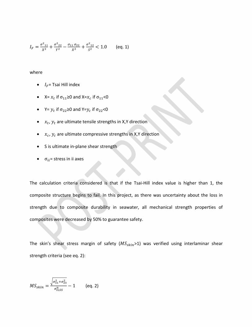
used to design complex structures. To verify the composite integrity calculations, the criterion
used was Tsai-Hill (Jones, 1999) (see eq.1):
𝐼𝐼𝐹𝐹 = 𝜎𝜎211𝑋𝑋2
+ 𝜎𝜎222𝑌𝑌2
− 𝜎𝜎11 𝜎𝜎22 𝑋𝑋2
+ 𝜎𝜎212𝑆𝑆2
< 1.0 (eq. 1)
where
• 𝐼𝐼𝐹𝐹= Tsai Hill index
• X= 𝑥𝑥𝑡𝑡 if σ11≥0 and X=𝑥𝑥𝑐𝑐 if σ11<0
• Y= 𝑦𝑦𝑡𝑡 if σ22≥0 and Y=𝑦𝑦𝑐𝑐 if σ22<0
• 𝑥𝑥𝑡𝑡, 𝑦𝑦𝑡𝑡 are ultimate tensile strengths in X,Y direction
• 𝑥𝑥𝑐𝑐, 𝑦𝑦𝑐𝑐 are ultimate compressive strengths in X,Y direction
• S is ultimate in-plane shear strength
• σ𝑖𝑖𝑖𝑖= stress in ii axes
The calculation criteria considered is that if the Tsai-Hill index value is higher than 1, the
composite structure begins to fail. In this project, as there was uncertainty about the loss in
strength due to composite durability in seawater, all mechanical strength properties of
composites were decreased by 50% to guarantee safety.
The skin’s shear stress margin of safety (𝑀𝑀𝑀𝑀𝑠𝑠𝑠𝑠𝑖𝑖𝑠𝑠>1) was verified using interlaminar shear
strength criteria (see eq. 2):
𝑀𝑀𝑀𝑀𝑠𝑠𝑠𝑠𝑖𝑖𝑠𝑠 =�𝜎𝜎312 +𝜎𝜎232
𝜎𝜎𝐼𝐼𝐼𝐼𝐼𝐼𝐼𝐼𝑢𝑢 − 1 (eq. 2)
where:
• 𝑀𝑀𝑀𝑀𝑠𝑠𝑠𝑠𝑖𝑖𝑠𝑠= skin’s shear stress margin of safety
• 𝜎𝜎𝐼𝐼𝐼𝐼𝑆𝑆𝑆𝑆𝑢𝑢 = maximum interlaminar shear strength
• σ𝑖𝑖𝑖𝑖= stress in ii axes
Core strength was verified (𝑀𝑀𝑀𝑀𝑐𝑐𝑐𝑐𝑐𝑐𝑐𝑐<1) using (see eqs. 3, 4 and 5):
𝜏𝜏13 = 𝑄𝑄1𝑐𝑐
(eq. 3)
𝜏𝜏23 = 𝑄𝑄2𝑐𝑐
(eq. 4)
𝑀𝑀𝑀𝑀𝑐𝑐𝑐𝑐𝑐𝑐𝑐𝑐 = 𝑆𝑆𝑠𝑠𝑠𝑠𝑆𝑆𝑠𝑠𝑠𝑠
�𝑆𝑆𝑠𝑠𝑠𝑠2 𝜏𝜏132 +𝑆𝑆𝑠𝑠𝑠𝑠2 𝜏𝜏232
− 1 (eq. 5)
where:
• 𝑀𝑀𝑀𝑀𝑐𝑐𝑐𝑐𝑐𝑐𝑐𝑐= core shear stress margin of safety
• 𝜏𝜏𝑖𝑖𝑖𝑖= shear stress following i axes
• 𝑐𝑐 = core thickness
• 𝑀𝑀𝑠𝑠𝑖𝑖= ultimate shear stress in i axes (w: width and l: longitudinal)
• 𝑄𝑄𝑖𝑖= shear load following i axe
Moreover, buckling and local instability sandwich failure modes, such as face wrinkling, intracell
buckling or dimpling, and local compression or crimping, were verified using the analysis of
sandwich structures design criteria (America Society for Metals [ASM], 2001).
Finite element model design
The numerical model was established using laminate FEM elastic and orthotropic elements to
simulate the composite material and the honeycomb. Solid elements were used to simulate
concrete, while filling material was not simulated but rather considered as a load. The model
had more than 28,000 nodes and consisted of 25,000 laminate parts and 3,000 solid elements.
As a buckling analysis was performed on this structure, the GFRP caisson was studied in the
final scenario where the mooring load needed to start buckling was calculated. The first
buckling mode occurred at an eigenvalue of 4.1. As shown in the buckling chart, the GFRP
caisson is far from buckling (see Figure 4 a-b).
Analyses of the loads considered in different scenarios and the stress results of the GRFP
caisson show that the most restrictive scenarios were CT2-b and CT1-d (see Table 3). Hence, the
composite laminate configuration was designed for these scenarios in each part of the GRFP
caisson. As evidenced in the stress analysis results, the GFRP caisson structure has a Tsai-Hill
index lower than 1, as maximum values are found at the bottom of the caisson but never
exceed 1. Furthermore, the structure’s bottom slab and vertical and base stiffeners were
analyzed, but all of them exhibited low Tsai-Hill index levels (see Table 4 and Figures 5 a-b-c-d).
Shear stress was also analyzed, but all results from the various scenarios were well below the
maximum value of 30 MPa. The honeycomb core was checked, and shear stresses were less
than 1.5 MPa and 2.1 MPa in different directions (see Figure 6 a-b). All shear stresses scenarios
provided MS values higher than 1 (see eq. 5). The composite sandwich buckling and local
instability failure modes were also verified, and MS was always found to be higher than 1.
The laminate configuration was examined in three different areas - area A, at the bottom,
which was 6 m high; area B, in the middle, which was from 6 m to 9.4 m high; and area C, the
rest of the GFRP caisson. The configuration was verified using the FEM, and angle measures
from the vertical cylindrical alignment were as follows:
• External skin (B45800G):
• A: 0/0/45/0/H90/0/45/0/0
• B: 0/45/0/HC90/0/45/0
• C: 0/0/HC90/0/0
• Internal skin (B45800G):
• A: 0/0/45/0/HC90/0/45/0/0
• B: 0/0/45/HC90/45/0/0
• Stiffeners (B45800G):
• 45/0/0/45/0/0/45/45/0/0/45/0/0
• Basement (UD1200HM):
• 45/0/0/45/0/0/45/45/0/0/45/0/0
The final configuration of the GFRP caissons found that their total weight using composite
materials was 20,000 kg. This allows for GFRP caissons to be pre-fabricated in a factory in the
south of Spain, shipped to Fuerteventura, assembled on the Puerto del Rosario dock and
launched with a light crane. In contrast, the concrete block option weighs 3,600,000 kg (180
times more) and thus requires a large surface for the installation of a concrete block
manufacturing factory (6,000 m2), an alternative that would affect the port’s functionality. The
GFRP caisson is also a sustainable solution for building ports because the installation process
reduces CO2 emissions by 75% compared to the concrete option.
CONSTRUCTION
Manufacture, transport and assembling of GFRP caissons
GFRP composite caissons were manufactured using a resin infusion technique in a factory
located in Jerez, a region in the south of Spain. First, the composite bases for the caissons were
manufactured, and all parts were prepared. The caisson base was constructed of 12
symmetrical elements, all of which were radial parts of the circular structure, which had an
external radius of 6 m. These foundation elements were designed to be moved by hand, not by
cranes, at the work site. The caisson walls were also manufactured in 12 elements. Each wall
element was made of two pieces, the outer skin, with a radius of 6 m, and the inner skin, with a
radius of 5.4 m, and were composed of composite sandwich panels. They were then bonded
together and pre-assembled at the factory. The assembly of the caisson walls was accomplished
using specially manufactured mechanical elements that overlapped both caisson walls and
were then pinned to the walls.
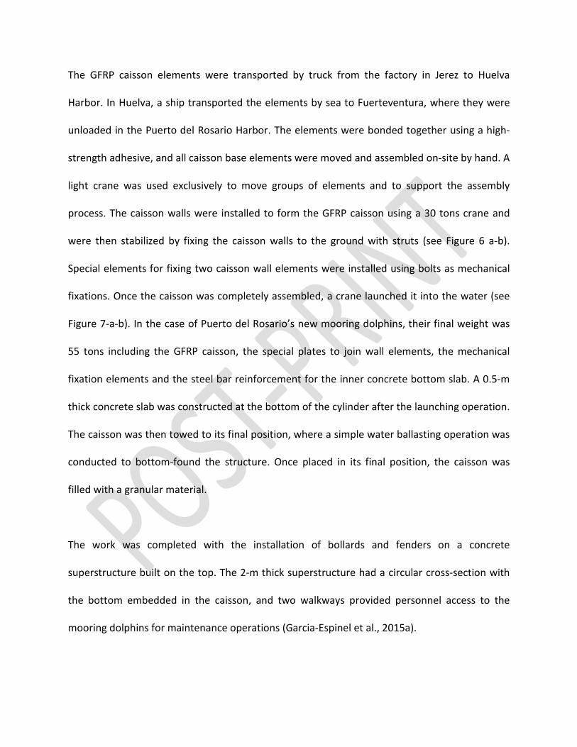
The GFRP caisson elements were transported by truck from the factory in Jerez to Huelva
Harbor. In Huelva, a ship transported the elements by sea to Fuerteventura, where they were
unloaded in the Puerto del Rosario Harbor. The elements were bonded together using a high-
strength adhesive, and all caisson base elements were moved and assembled on-site by hand. A
light crane was used exclusively to move groups of elements and to support the assembly
process. The caisson walls were installed to form the GFRP caisson using a 30 tons crane and
were then stabilized by fixing the caisson walls to the ground with struts (see Figure 6 a-b).
Special elements for fixing two caisson wall elements were installed using bolts as mechanical
fixations. Once the caisson was completely assembled, a crane launched it into the water (see
Figure 7-a-b). In the case of Puerto del Rosario’s new mooring dolphins, their final weight was
55 tons including the GFRP caisson, the special plates to join wall elements, the mechanical
fixation elements and the steel bar reinforcement for the inner concrete bottom slab. A 0.5-m
thick concrete slab was constructed at the bottom of the cylinder after the launching operation.
The caisson was then towed to its final position, where a simple water ballasting operation was
conducted to bottom-found the structure. Once placed in its final position, the caisson was
filled with a granular material.
The work was completed with the installation of bollards and fenders on a concrete
superstructure built on the top. The 2-m thick superstructure had a circular cross-section with
the bottom embedded in the caisson, and two walkways provided personnel access to the
mooring dolphins for maintenance operations (Garcia-Espinel et al., 2015a).
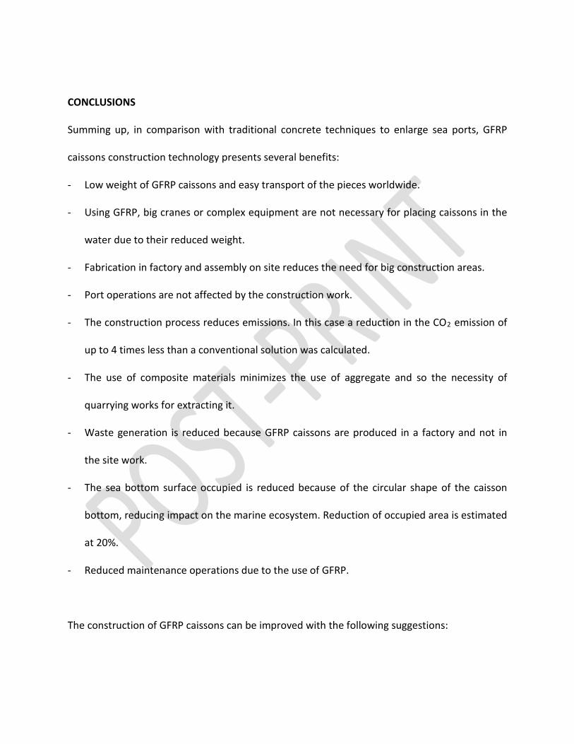
CONCLUSIONS
Summing up, in comparison with traditional concrete techniques to enlarge sea ports, GFRP
caissons construction technology presents several benefits:
- Low weight of GFRP caissons and easy transport of the pieces worldwide.
- Using GFRP, big cranes or complex equipment are not necessary for placing caissons in the
water due to their reduced weight.
- Fabrication in factory and assembly on site reduces the need for big construction areas.
- Port operations are not affected by the construction work.
- The construction process reduces emissions. In this case a reduction in the CO2 emission of
up to 4 times less than a conventional solution was calculated.
- The use of composite materials minimizes the use of aggregate and so the necessity of
quarrying works for extracting it.
- Waste generation is reduced because GFRP caissons are produced in a factory and not in
the site work.
- The sea bottom surface occupied is reduced because of the circular shape of the caisson
bottom, reducing impact on the marine ecosystem. Reduction of occupied area is estimated
at 20%.
- Reduced maintenance operations due to the use of GFRP.
The construction of GFRP caissons can be improved with the following suggestions:
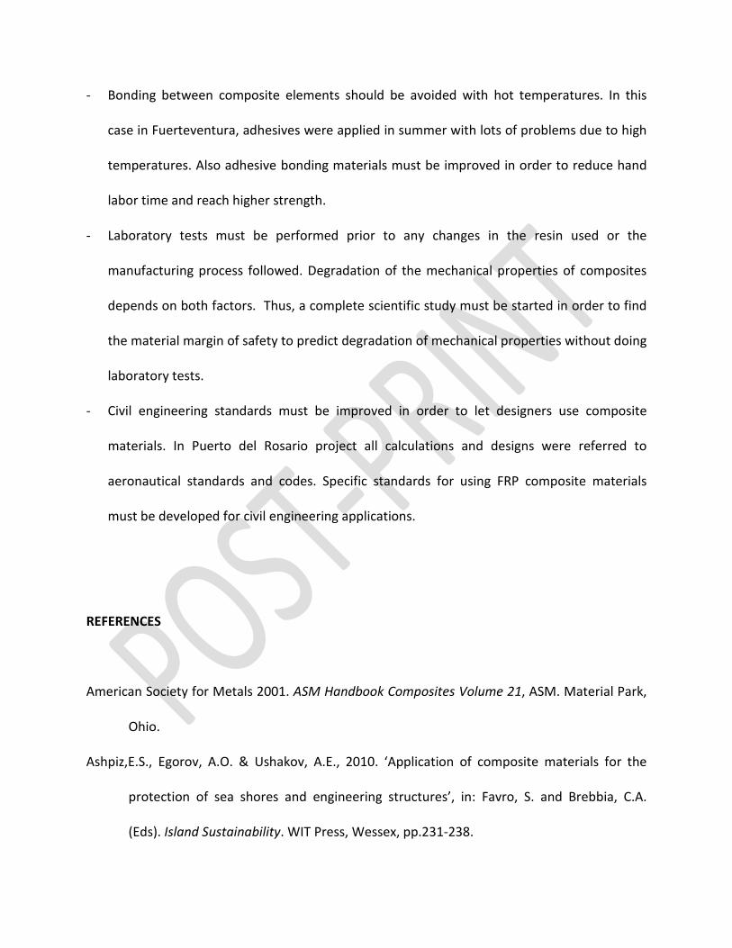
- Bonding between composite elements should be avoided with hot temperatures. In this
case in Fuerteventura, adhesives were applied in summer with lots of problems due to high
temperatures. Also adhesive bonding materials must be improved in order to reduce hand
labor time and reach higher strength.
- Laboratory tests must be performed prior to any changes in the resin used or the
manufacturing process followed. Degradation of the mechanical properties of composites
depends on both factors. Thus, a complete scientific study must be started in order to find
the material margin of safety to predict degradation of mechanical properties without doing
laboratory tests.
- Civil engineering standards must be improved in order to let designers use composite
materials. In Puerto del Rosario project all calculations and designs were referred to
aeronautical standards and codes. Specific standards for using FRP composite materials
must be developed for civil engineering applications.
REFERENCES
American Society for Metals 2001. ASM Handbook Composites Volume 21, ASM. Material Park,
Ohio.
Ashpiz,E.S., Egorov, A.O. & Ushakov, A.E., 2010. ‘Application of composite materials for the
protection of sea shores and engineering structures’, in: Favro, S. and Brebbia, C.A.
(Eds). Island Sustainability. WIT Press, Wessex, pp.231-238.
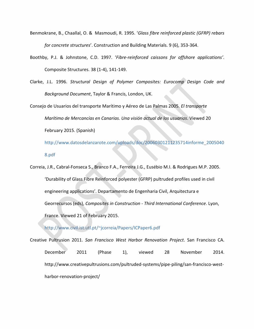
Benmokrane, B., Chaallal, O. & Masmoudi, R. 1995. ‘Glass fibre reinforced plastic (GFRP) rebars
for concrete structures’. Construction and Building Materials. 9 (6), 353-364.
Boothby, P.J. & Johnstone, C.D. 1997. ‘Fibre-reinforced caissons for offshore applications’.
Composite Structures. 38 (1-4), 141-149.
Clarke, J.L. 1996. Structural Design of Polymer Composites: Eurocomp Design Code and
Background Document, Taylor & Francis, London, UK.
Consejo de Usuarios del transporte Marítimo y Aéreo de Las Palmas 2005. El transporte
Marítimo de Mercancías en Canarias. Una visión actual de los usuarios. Viewed 20
February 2015. (Spanish)
http://www.datosdelanzarote.com/uploads/doc/20060301211235714informe_2005040
8.pdf
Correia, J.R., Cabral-Fonseca S., Branco F.A., Ferreira J.G., Eusébio M.I. & Rodrigues M.P. 2005.
‘Durability of Glass Fibre Reinforced polyester (GFRP) pultruded profiles used in civil
engineering applications’. Departamento de Engenharia Civil, Arquitectura e
Georrecursos (eds), Composites in Construction - Third International Conference. Lyon,
France. Viewed 21 of February 2015.
http://www.civil.ist.utl.pt/~jcorreia/Papers/ICPaper6.pdf
Creative Pultrusion 2011. San Francisco West Harbor Renovation Project. San Francisco CA.
December 2011 (Phase 1), viewed 28 November 2014.
http://www.creativepultrusions.com/pultruded-systems/pipe-piling/san-francisco-west-
harbor-renovation-project/
Creese R.C., Gangarao H. 2004. Polymer composites III. Transportation infrastructure, defense
and novel applications of composites. Destech publications, Pennsylvania, PA.
Delf Infra Composites 2014. Bridges and bridge decks with composites. Nijmegen, The
Netherlands, viewed 21 February 2015. http://www.infracomposites.com/bridges-and-
bridge-decks-with-composites.html
Franco, L., 1994. ‘Vertical breakwaters: the Italian experience’. Coastal Engineering. 22 (1-2),
31-55.
Frihy, O.E., 2001. ‘The necessity of environmental impact assessment (EIA) in implementing
coastal projects: lessons learned from the Egyptian Mediterranean Coast’. Ocean &
Coastal Management. 44 (7-8), 489-516
Garcia-Espinel, J.D., Alvarez-Garcia-Lubén, R., Gonzalez-Herrero, J.M. & Castro-Fresno, D.,
2015a. ‘Glass fiber-reinforced polymer caissons used for construction of mooring
dolphins in Puerto del Rosario harbor (Fuerteventura, Canary Islands)’. Coastal
Engineering. 98. 16–25
García-Espinel, J.D., Ayala-Luna, J. & Clemente-Ortega, L.R. 2012. ‘Ejemplo del uso de materiales
innovadores en la ingeniería civil. Pasarela peatonal en Cuenca’. Congreso Nacional de
Ingeniería Civil, Valencia. (Spanish)
Garcia-Espinel, J.D.; Castro-Fresno, D.; Parbole Gayo, P. & Ballester-Muñoz F. 2015b. ‘Effects of
sea water environment on glass fiber reinforced plastic materials used for marine civil
engineering constructions’. Material and Design. 66. 46–50
García-Espinel, J.D. & Del Amo-Sanz, E. 2010. ‘Duplicación de la M-III y variante de Fuente el Saz
de Jarama’. Cauce 2000. 32-39. (Spanish)
Gellert, E.P. & Turley, D.M., 1999. ‘Seawater immersion ageing of glass-fibre reinforced
polymer laminates for marine applications’. Composites Part A: Applied Science and
Manufacturing, 30 (11), 1259-1265.
Hoshikuma, J., Kawashima, K., Nagaya, K., & Taylor, A., 1997. ‘Stress-Strain model for confined
reinforced concrete in bridge piers’. J. Structural Engineering.123 (5), 624–633.
Jones, R.M. 1999. Mechanics of composite materials, Taylor & Francis, Philadelphia, PA.
Kootsookos A., Mouritz A.P., 2004. ‘Seawater durability of glass- and carbon-polymer
composites’. Composites Science and Technology. 64 (10-11), 1503-1511
Kumar,B.G., Singh, R.P. & Nakamura, T., 2002. ‘Degradation of Carbon Fiber-reinforced Epoxy
Composites by Ultraviolet Radiation and Condensation’. Journal of Composite Materials.
36 (24), 2713-2733.
Liao K., Schultheisz C.R., Hunston D.L., 1999. ‘Effects of environmental aging on the properties
of pultruded GFRP Composites’. Composites Part B: Engineering. 30 (5), 485-493.
Mieres, J.M., Calvo,I., Miravete, A., Gutiérrez, E., Shahidi, E., López, C., J. Cuartero, J., Comino,
P., & Guzmán de Villoria, R., 2006. ‘Description of a traffic bridge of the Cantabrian
Speedway made of composite materials’. Materiales de Construcción. 56 (284), 81-86.
Moreau, Jeff. 2004. Carbon fiber re-enforced composite sheet piling segments. US Patent
number 0126193. Sol. 10/702,351.
Moreau, Jeff. Multipanel seawall segment. 2005. US Patent number 0058514 A1. Sol.
10/939,708.
Moreau; Jeff. 2007. Re-enforced composite sheet piling segments. US Patent number 7182551.
Sol. 10/286,564.
Nguyen,T., Aouadi, K., Alsheh, D. & Chin,J. 1997. ‘Effects of Civil Engineering Environments of
Interfacial Properties of Polymer/Glass Fiber Composites’, in Hui, D., (ed). Composites
Engineering, 4th International Conference. International Community for Composites
Engineering (ICCE/4). University of New, Hawaii, pp 725-726.
Poodts, E., Minak, G. & Zucchelli, A., 2013. ‘Impact of sea-water on the quasi static and fatigue
flexural properties of GFRP’. Composite Structures. 97, 222-230.
Potyrała P.B., 2011. Use of Fibre Reinforced Polymer Composites in Bridge Construction. State of
the Art in Hybrid and All-Composite Structures. Universidad Politécnica de Cataluña.
Barcelona. BA.
Puertos del Estado 2008. Guía de buenas prácticas para la ejecución de obras marítimas, PE,
Madrid. (Spanish)
Shan, Y. & Liao, K. 2002. ‘Environmental fatigue behavior and life prediction of unidirectional
glass–carbon/epoxy hybrid composites’. International Journal of Fatigue. 24 (8), 847-
859.
Spanish Standards, 2008. EHE-08. Instrucción del hormigón estructural. Ministerio de Fomento.
Gobierno de España. (Spanish)
Spanish Standards 2011. ROM 2.0-11 Recomendaciones para el proyecto y ejecución en las
Obras de Atraque y Amarre. Ministerio de Fomento. Gobierno de España. (Spanish)
Strongwell 2009. Leri footbridge buil with strongwell’s lightweight, corrosion resistans FRP.
Strongwell, viewed 21 February 2015. http://www.strongwell.com/news/leri-
footbridgebuilt-with-strongwells-lightweight-corrosion-resistant-frp/
Wagner,P.A., Little,B.J., Hart. K.R. & Ray, R.I., 1996. ‘Biodegradation of Composite Materials’.
International Biodeterioration & Biodegradation. 38 (2), 125-132.
Wei,B., Cao,H., Song,S. 2011. ‘Degradation of basalt fibre and glass fibre/epoxy resin
composites in seawater’. Corrosion Science. 53 (1), 426-431.
Figure Captions
Figure 1 - General view of the construction of two mooring dolphins in Puerto del Rosario
(Fuerteventura, Spain) (image by José Daniel García Espinel)
Figure 2 - GFRP caisson structure for mooring dolphins in Puerto del Rosario (Fuerteventura,
Spain) (a) top view; (b) general view; (c) cross section
Figure 3 - Details of wave conditions used in the GFRP design; (a) pressure of wave crest; (b)
pressure of wave sine
Figure 4.- Details of the FEM model and first buckling mode for mooring load (λ=4.1); (a) FEM
elements model; (b) first buckling mode for mooring load (Eigenvalue=4.1)
Figure 5 Tsai-Hill failure index for the (a) external side; (b) internal side, (c) vertical wall
stiffeners, and (d) base stiffeners
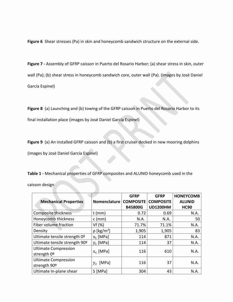
Figure 6 Shear stresses (Pa) in skin and honeycomb sandwich structure on the external side.
Figure 7 - Assembly of GFRP caisson in Puerto del Rosario Harbor; (a) shear stress in skin, outer
wall (Pa); (b) shear stress in honeycomb sandwich core, outer wall (Pa). (images by José Daniel
García Espinel)
Figure 8 (a) Launching and (b) towing of the GFRP caisson in Puerto del Rosario Harbor to its
final installation place (images by José Daniel García Espinel)
Figure 9 (a) An installed GFRP caisson and (b) a first cruiser docked in new mooring dolphins
(images by José Daniel García Espinel)
Table 1 - Mechanical properties of GFRP composites and ALUNID honeycomb used in the
caisson design
Mechanical Properties Nomenclature GFRP
COMPOSITE B45800G
GFRP COMPOSITE UD1200HM
HONEYCOMB ALUNID
HC90 Composite thickness t (mm) 0.72 0.69 N.A. Honeycomb thickness c (mm) N.A. N.A. 50 Fiber volume fraction Vf (%) 71.7% 71.1% N.A. Density ρ [kg/m3] 1,905 1,905 83 Ultimate tensile strength 0º xt [MPa] 114 871 N.A. Ultimate tensile strength 90º yt [MPa] 114 37 N.A. Ultimate Compression strength 0º xc [MPa] 116 610 N.A.
Ultimate Compression strength 90º yc [MPa] 116 37 N.A.
Ultimate In-plane shear S [MPa] 304 43 N.A.
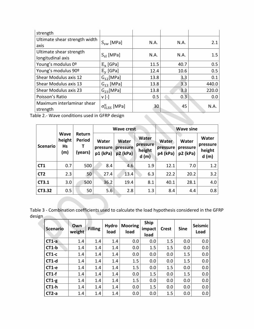
strength Ultimate shear strength width axis Ssw [MPa] N.A. N.A. 2.1
Ultimate shear strength longitudinal axis Ssl [MPa] N.A. N.A. 1.5
Young’s modulus 0º Ex [GPa] 11.5 40.7 0.5 Young’s modulus 90º Ey [GPa] 12.4 10.6 0.5 Shear Modulus axis 12 G12[MPa] 13.8 3.3 0.1 Shear Modulus axis 13 G13 [MPa] 13.8 3.3 440.0 Shear Modulus axis 23 G23[MPa] 13.8 3.3 220.0 Poisson’s Ratio ν [-] 0.5 0.3 0.0 Maximum interlaminar shear strength σILSSu [MPa] 30 45 N.A.
Table 2.- Wave conditions used in GFRP design
Scenario
Wave height
Hs (m)
Return Period
T (years)
Wave crest Wave sine
Water pressure p1 (kPa)
Water pressure p2 (kPa)
Water pressure
height d (m)
Water pressure p4 (kPa)
Water pressure p2 (kPa)
Water pressure
height d (m)
CT1 0.7 500 8.4 4.6 1.9 12.1 7.0 1.2
CT2 2.3 50 27.4 13.4 6.3 22.2 20.2 3.2
CT3.1 3.0 500 36.2 19.4 8.1 40.1 28.1 4.0
CT3.32 0.5 50 5.6 2.8 1.3 8.4 4.4 0.8
Table 3 - Combination coefficients used to calculate the load hypothesis considered in the GFRP design
Scenario Own weight Filling Hydro
load Mooring
load
Ship impact
load Crest Sine Seismic
Load
CT1-a 1.4 1.4 1.4 0.0 0.0 1.5 0.0 0.0 CT1-b 1.4 1.4 1.4 0.0 1.5 1.5 0.0 0.0 CT1-c 1.4 1.4 1.4 0.0 0.0 0.0 1.5 0.0 CT1-d 1.4 1.4 1.4 1.5 0.0 0.0 1.5 0.0 CT1-e 1.4 1.4 1.4 1.5 0.0 1.5 0.0 0.0 CT1-f 1.4 1.4 1.4 0.0 1.5 0.0 1.5 0.0 CT1-g 1.4 1.4 1.4 1.5 0.0 0.0 0.0 0.0 CT1-h 1.4 1.4 1.4 0.0 1.5 0.0 0.0 0.0 CT2-a 1.4 1.4 1.4 0.0 0.0 1.5 0.0 0.0
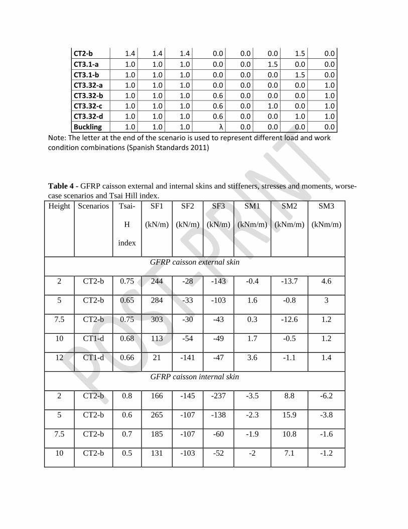
CT2-b 1.4 1.4 1.4 0.0 0.0 0.0 1.5 0.0 CT3.1-a 1.0 1.0 1.0 0.0 0.0 1.5 0.0 0.0 CT3.1-b 1.0 1.0 1.0 0.0 0.0 0.0 1.5 0.0 CT3.32-a 1.0 1.0 1.0 0.0 0.0 0.0 0.0 1.0 CT3.32-b 1.0 1.0 1.0 0.6 0.0 0.0 0.0 1.0 CT3.32-c 1.0 1.0 1.0 0.6 0.0 1.0 0.0 1.0 CT3.32-d 1.0 1.0 1.0 0.6 0.0 0.0 1.0 1.0 Buckling 1.0 1.0 1.0 λ 0.0 0.0 0.0 0.0
Note: The letter at the end of the scenario is used to represent different load and work condition combinations (Spanish Standards 2011) Table 4 - GFRP caisson external and internal skins and stiffeners, stresses and moments, worse-case scenarios and Tsai Hill index. Height Scenarios Tsai-
H
index
SF1
(kN/m)
SF2
(kN/m)
SF3
(kN/m)
SM1
(kNm/m)
SM2
(kNm/m)
SM3
(kNm/m)
GFRP caisson external skin
2 CT2-b 0.75 244 -28 -143 -0.4 -13.7 4.6
5 CT2-b 0.65 284 -33 -103 1.6 -0.8 3
7.5 CT2-b 0.75 303 -30 -43 0.3 -12.6 1.2
10 CT1-d 0.68 113 -54 -49 1.7 -0.5 1.2
12 CT1-d 0.66 21 -141 -47 3.6 -1.1 1.4
GFRP caisson internal skin
2 CT2-b 0.8 166 -145 -237 -3.5 8.8 -6.2
5 CT2-b 0.6 265 -107 -138 -2.3 15.9 -3.8
7.5 CT2-b 0.7 185 -107 -60 -1.9 10.8 -1.6
10 CT2-b 0.5 131 -103 -52 -2 7.1 -1.2
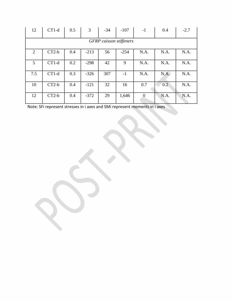
12 CT1-d 0.5 3 -34 -107 -1 0.4 -2.7
GFRP caisson stiffeners
2 CT2-b 0.4 -213 56 -254 N.A. N.A. N.A.
5 CT1-d 0.2 -298 42 9 N.A. N.A. N.A.
7.5 CT1-d 0.3 -326 307 -1 N.A. N.A. N.A.
10 CT2-b 0.4 -121 32 16 0.7 0.2 N.A.
12 CT2-b 0.4 -372 29 1,646 0 N.A. N.A.
Note: SFi represent stresses in i axes and SMi represent moments in i axes