gardening pond elite series
TRANSCRIPT
ELITE SERIESCOMMERCIAL GRADE
GARDENING | IRRIGATIONPOND | FOUNTAIN
ELECTRONICJET PUMP
727194 | 900 GPH
ELECTRONICMULTISTAGE PUMP
727196 | 1416 GPH WARRANTY2YEAR
ELECTRIC MULTISTAGEAND JET PUMPS
INSTRUCTIONS FOR INSTALLATION AND MAINTENANCE
2
INDEX 1. PUMPABLE LIQUIDS ................................................................................................4 2. TECHNICAL SPECIFICATIONS ..................................................................................4 3. DIMENSIONS AND FEATURES ..................................................................................5 4. PERFORMANCE CURVES AND FLOW RATES ............................................................6 5. PLANNING GRID.......................................................................................................7 6. MANAGEMENT AND INSTALLATION ........................................................................8 7. START-UP .................................................................................................................9 8. ELECTRONIC CONTROL INTERFACE ......................................................................10 8.1 OVERVIEW OF THE FEATURES .........................................................................10 8.1.1 Description of the display ................................................................. 11-13 8.2 DESCRIPTION OF THE FUNCTIONS ........................................................... 13-14 8.2.1 Pump ON/OFF (AUTO MODE, MANUAL MODE) .......................................13 8.2.2 Priming phase .........................................................................................13 8.2.3 Alarm reset .............................................................................................13 8.2.4 Power ON/OFF indicator .........................................................................14 8.2.5 Pump ON/OFF indicator .........................................................................14 8.2.6 Alarms indicator .....................................................................................14 8.2.7 Dry run protection ...................................................................................14 8.2.8 ANTI-LEAKAGE .......................................................................................14 8.2.9 Max pump on ..........................................................................................14 8.2.10 Pressure sensor alarm ..........................................................................14 8.3 FIRST START UP ..............................................................................................15 8.3.1 Test on LEDs ...........................................................................................15 8.3.2 First priming ...........................................................................................15 8.4 NORMAL OPERATIONS WITH CUT-OUT DISABLED ..........................................15 8.5 NORMAL OPERATIONS WITH CUT-OUT ENABLED ...........................................15 9. PRECAUTIONS .......................................................................................................15 10. MAINTENANCE AND CLEANING ....................................................................... 15-16 11. TROUBLESHOOTING ..............................................................................................17 12. LIMITED WARRANTY ..............................................................................................18 13. NOTES .............................................................................................................. 19-20
3
WARNING: Read entire instruction manual carefully before using.
REMOVE THE POWER PLUG FROM THE ELECTRICAL SOCKET BEFORE HANDLING THE PUMP TO AVOID ELECTRIC SHOCK.
ABSOLUTELY AVOID DRY OPERATION.
PROTECT THE PUMP AGAINST INCLEMENT WEATHER.
The pump is equipped with a thermal overload safety device. In the event of overheating, this device automatically switches off the pump. The cooling time is roughly 15 to 20 minutes, then the pump automatically comes on again. If the overload cutout is tripped, it is essential to identify and deal with the cause of the overheating. (See Troubleshooting). Do not use in swimming pools, ponds or basins where people are present.Do not use for pumping hydrocarbons (petrol, diesel fuel, combustible oils, solvents). Do not pump continuously for long periods of time unless in the case of emergency.
Always clean the pumps before storage. See the chapter “Maintenance and Cleaning”.
4
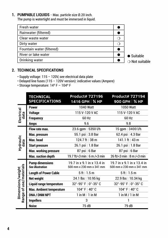
1. PUMPABLE LIQUIDS - Max. particle size Ø.20 inch. The pump is watertight and must be immersed in liquid.
2. TECHNICAL SPECIFICATIONS • Supply voltage: 115 – 120V, see electrical data plate • Delayed line fuses (115 – 120V version): indicative values (Ampere) • Storage temperature: 14º F – 104º F
Fresh water ●
Rainwater (filtered) ●
Clear waste water ❍
Dirty water ❍
Fountain water (filtered) ●
River or lake water ●
Drinking water ●● Suitable❍ Not suitable
Elec
tric
alda
taH
ydra
ulic
data
PowerVoltage
AmpsFlow rate max.Max. pressureMax. headStart pressureMax. working pressureMax. suction depth
Pump dimensionsSee illustration
Liquid range temperatureMax. Ambient temperatureDNA / DNM NPT
Net weightLength of Power Cable
1040 Watt115 V-120 V AC
9.623.6 gpm | 5350 l/h
55.1 psi | 3.8 Bar124.7 ft | 38 m
26.1 psi | 1.8 Bar87 psi | 6 Bar
19.7 ft/<3 min | 6 m /<3 min
19.7 in x 9.1 in x 13.4 in500 mm x 230 mm x 341 mm
5 ft | 1.5 m
32°-95° F | 0°-35° C104° F | 40° C1 in M / 1 in M
3
24.1 lbs | 10.95 kg
75 dB
1050 Watt115 V-120 V AC
9.815 gpm | 3400 l/h62.4 psi | 4.3 Bar
141.1 ft | 43 m26.1 psi | 1.8 Bar
87 psi | 6 Bar26 ft/<3 min | 8 m /<3 min
19.7 in x 9.1 in x 13.4 in500 mm x 230 mm x 341 mm
5 ft | 1.5 m
32°-95° F | 0°-35° C104° F | 40° C1 in M / 1 in M
179 dB
22.9 lbs | 10.34 kg
Frequency 60 Hz 60 Hz
Dim
ensi
ons/
wei
ght
Rang
e of
use
/mat
eria
ls
ImpellersNoise
TECHNICALSPECIFICATIONS 1416 GPH | ¾ HP 900 GPH | ¾ HP
Product# 727196 Product# 727194
5
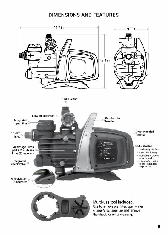
DIMENSIONS AND FEATURES
1” NPT inlet
1” NPT outlet
Integrated check valve
Anti-vibrationrubber feet
Comfortable handleIntegrated
pre-filter
Flow indicator fan
Multistage Pumppart #727196 hasthree (3) impellers
Multi-use tool included.Use to remove pre-filter, open water charge/discharge tap and removethe check valve for cleaning.
LED display• User friendly interface.• Pressure indicating.• Allows user to choose operation modes.• Built-in safety device for anti-leak and dry run protection.
Water cooled motor
9.1 in19.7 in
13.4 in
6
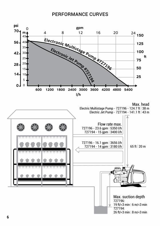
PERFORMANCE CURVES
Max. head Electric Multistage Pump - 727196 - 124.7 ft | 38 m
Electric Jet Pump - 727194 - 141.1 ft | 43 m
Max. suction depth727196:19 ft/<3 min | 6 m/<3 min727194:26 ft/<3 min | 8 m/<3 min
Flow rate max. 727196 - 23.6 gpm | 5350 l/h
727194 - 15 gpm | 3400 l/h
727196 - 16.1 gpm | 3656 l/h 727194 - 14 gpm | 3180 l/h 65 ft | 20 m
4 8 12 16 20
l/h
m150
125
100
75
50
25
0
14
28
42
56
70psi
40
45
35
30
25
20
15
10
5
0
gpm24
0
600 1200 1800 2400 3000 3600 4200 4800 5400
Electronic Multistage Pump #727196
Electronic Jet Pump #727194

7
PLANNING GRID
8
THE PUMP MUST BE SUPPORTED BY A BASE. NEVER SUSPEND THE PUMP FROM PIPES.
3. MANAGEMENT 3.1 Storage: Pump must be stored in a dry, dust free covered area that is free from vibrations. Keep the pump in its original packaging until time of installation.
3.2 Transport: Avoid subjecting the pump to needless impacts and collisions.
4. WARNINGS
DO NOT CARRY PUMP BY THE POWER CABLE. ALWAYS CARRY PUMP USING THE HANDLE. • Never allow the pump to run dry. • It is recommended to open/close the venting/drainage caps (2 and 6) without applying excessive force.
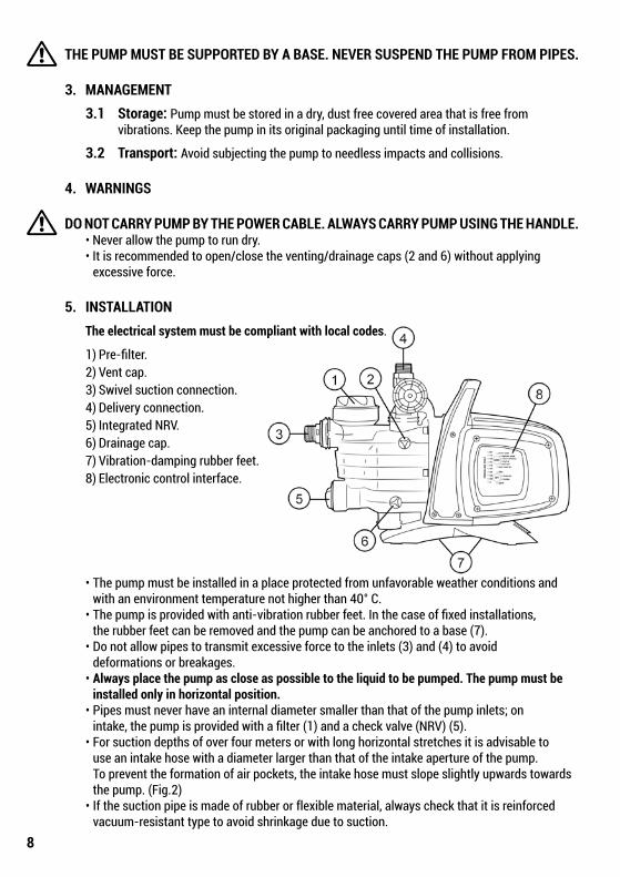
5. INSTALLATION The electrical system must be compliant with local codes.
1) Pre-filter. 2) Vent cap. 3) Swivel suction connection. 4) Delivery connection. 5) Integrated NRV. 6) Drainage cap. 7) Vibration-damping rubber feet. 8) Electronic control interface.
• The pump must be installed in a place protected from unfavorable weather conditions and with an environment temperature not higher than 40° C. • The pump is provided with anti-vibration rubber feet. In the case of fixed installations, the rubber feet can be removed and the pump can be anchored to a base (7). • Do not allow pipes to transmit excessive force to the inlets (3) and (4) to avoid deformations or breakages. • Always place the pump as close as possible to the liquid to be pumped. The pump must be installed only in horizontal position. • Pipes must never have an internal diameter smaller than that of the pump inlets; on intake, the pump is provided with a filter (1) and a check valve (NRV) (5). • For suction depths of over four meters or with long horizontal stretches it is advisable to use an intake hose with a diameter larger than that of the intake aperture of the pump. To prevent the formation of air pockets, the intake hose must slope slightly upwards towards the pump. (Fig.2) • If the suction pipe is made of rubber or flexible material, always check that it is reinforced vacuum-resistant type to avoid shrinkage due to suction.
9
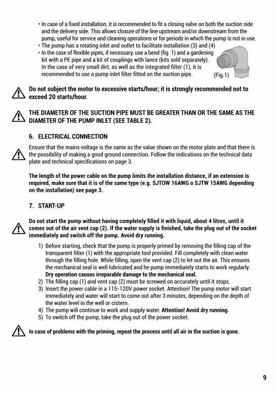
• In case of a fixed installation, it is recommended to fit a closing valve on both the suction side and the delivery side. This allows closure of the line upstream and/or downstream from the pump, useful for service and cleaning operations or for periods in which the pump is not in use. • The pump has a rotating inlet and outlet to facilitate installation (3) and (4) • In the case of flexible pipes, if necessary, use a bend (fig. 1) and a gardening kit with a PE pipe and a kit of couplings with lance (kits sold separately). In the case of very small dirt, as well as the integrated filter (1), it is recommended to use a pump inlet filter fitted on the suction pipe.
Do not subject the motor to excessive starts/hour; it is strongly recommended not to exceed 20 starts/hour.
THE DIAMETER OF THE SUCTION PIPE MUST BE GREATER THAN OR THE SAME AS THE DIAMETER OF THE PUMP INLET (SEE TABLE 2). 6. ELECTRICAL CONNECTIONEnsure that the mains voltage is the same as the value shown on the motor plate and that there is the possibility of making a good ground connection. Follow the indications on the technical data plate and technical specifications on page 3.
The length of the power cable on the pump limits the installation distance, if an extension is required, make sure that it is of the same type (e.g. SJTOW 16AWG o SJTW 15AWG depending on the installation) see page 3. 7. START-UP
Do not start the pump without having completely filled it with liquid, about 4 litres, until it comes out of the air vent cap (2). If the water supply is finished, take the plug out of the socket immediately and switch off the pump. Avoid dry running.
1) Before starting, check that the pump is properly primed by removing the filling cap of the transparent filter (1) with the appropriate tool provided. Fill completely with clean water through the filling hole. While filling, open the vent cap (2) to let out the air. This ensures the mechanical seal is well lubricated and he pump immediately starts to work regularly. Dry operation causes irreparable damage to the mechanical seal. 2) The filling cap (1) and vent cap (2) must be screwed on accurately until it stops. 3) Insert the power cable in a 115-120V power socket. Attention! The pump motor will start immediately and water will start to come out after 3 minutes, depending on the depth of the water level in the well or cistern. 4) The pump will continue to work and supply water. Attention! Avoid dry running. 5) To switch off the pump, take the plug out of the power socket.
In case of problems with the priming, repeat the process until all air in the suction is gone.
(Fig.1)

10
8. ELECTRONIC CONTROL INTERFACE
8.1 Overview of the features
FEATURE DESCRIPTION PARAMETERSController board voltage, frequency 1x115-120V, 60HzPower on/off indicator ●
Motor on/off indicator ●
Alarms indicator ●
Pressure indicator ●
Mode indicator ●
Auto Mode ●
Manual Mode ❍
Dry-running protection ●
Anti-leakage ❍
Max pump on protection ❍ (30 minutes)Cut-in pressure ❍ Variable (22 – 44 psi)Cut-out pressure ❍ (Cut-in + 14.5 psi)Auto priming ●
Selection buttons ●● Fixed❍ Selectable
(A)LED pressure
indicators
(B)MODE selection
button
(C)SET selection
button
11
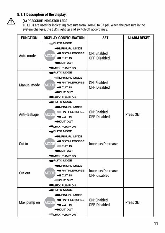
8.1.1 Description of the display: (A) PRESSURE INDICATOR LEDS 10 LEDs are used for indicating pressure from From 0 to 87 psi. When the pressure in the system changes, the LEDs light up and switch off accordingly.
FUNCTION DISPLAY CONFIGURATION SET ALARM RESET
Auto mode ON: EnabledOFF: Disabled
Manual mode ON: EnabledOFF: Disabled
Anti-leakage ON: EnabledOFF: Disabled Press SET
Cut in Increase/Decrease
Cut out Increase/DecreaseOFF: disabled
Max pump on ON: EnabledOFF: Disabled Press SET
12
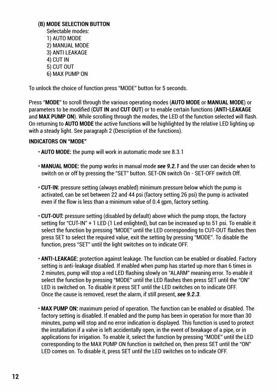
(B) MODE SELECTION BUTTON Selectable modes: 1) AUTO MODE 2) MANUAL MODE 3) ANTI LEAKAGE 4) CUT IN 5) CUT OUT 6) MAX PUMP ON
To unlock the choice of function press “MODE” button for 5 seconds.
Press “MODE” to scroll through the various operating modes (AUTO MODE or MANUAL MODE) or parameters to be modified (CUT IN and CUT OUT) or to enable certain functions (ANTI-LEAKAGE and MAX PUMP ON). While scrolling through the modes, the LED of the function selected will flash. On returning to AUTO MODE the active functions will be highlighted by the relative LED lighting up with a steady light. See paragraph 2 (Description of the functions).
INDICATORS ON “MODE”
• AUTO MODE: the pump will work in automatic mode see 8.3.1
• MANUAL MODE: the pump works in manual mode see 9.2.1 and the user can decide when to switch on or off by pressing the “SET” button. SET-ON switch On - SET-OFF switch Off.
• CUT-IN: pressure setting (always enabled) minimum pressure below which the pump is activated, can be set between 22 and 44 psi (factory setting 26 psi) the pump is activated even if the flow is less than a minimum value of 0.4 gpm, factory setting.
• CUT-OUT: pressure setting (disabled by default) above which the pump stops, the factory setting for “CUT-IN” + 1 LED (1 Led enlighted), but can be increased up to 51 psi. To enable it select the function by pressing “MODE” until the LED corresponding to CUT-OUT flashes then press SET to select the required value, exit the setting by pressing “MODE”. To disable the function, press “SET” until the light switches on to indicate OFF.
• ANTI-LEAKAGE: protection against leakage. The function can be enabled or disabled. Factory setting is anti-leakage disabled. If enabled when pump has started up more than 6 times in 2 minutes, pump will stop a red LED flashing slowly on “ALARM” meaning error. To enable it select the function by pressing “MODE” until the LED flashes then press SET until the “ON” LED is switched on. To disable it press SET until the LED switches on to indicate OFF. Once the cause is removed, reset the alarm, if still present, see 9.2.3.
• MAX PUMP ON: maximum period of operation. The function can be enabled or disabled. The factory setting is disabled. If enabled and the pump has been in operation for more than 30 minutes, pump will stop and no error indication is displayed. This function is used to protect the installation if a valve is left accidentally open, in the event of breakage of a pipe, or in applications for irrigation. To enable it, select the function by pressing “MODE” until the LED corresponding to the MAX PUMP ON function is switched on, then press SET until the “ON” LED comes on. To disable it, press SET until the LED switches on to indicate OFF.
13
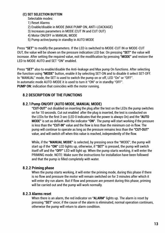
(C) SET SELECTION BUTTON Selectable modes: 1) Reset Alarms 2) Enable/disable in MODE (MAX PUMP ON, ANTI-LEACKAGE) 3) Increases parameters in MODE (CUT IN and CUT OUT) 4) Motor ON/OFF in MANUAL MODE 5) Pump active/pump in standby in AUTO MODE
Press “SET” to modify the parameters. If the LED is switched to MODE-CUT IN or MODE-CUT OUT, the value will be shown on the pressure indication LED bar. On pressing “SET” the value will increase. After setting the required value, exit the modification by pressing “MODE” and restore the LED to MODE-AUTO and SET “ON” enabled.
Press “SET” also to enable/disable the Anti-leakage and Max pump On functions. After selecting the function using “MODE” button, enable it by selecting SET-ON and to disable it select SET-OFF.In “MANUAL” mode, the SET is used to switch the pump on or off, LED “On” or “OFF”.In automatic mode AUTO-MODE it is used to turn it “ON” or in standby “OFF”.PUMP ON: indication that coincides with the motor running.
8.2 DESCRIPTION OF THE FUNCTIONS
8.2.1 Pump ON/OFF (AUTO MODE, MANUAL MODE)“CUT-OUT” out disabled on inserting the plug after the test on the LEDs the pump switches on for 10 seconds. Cut out enabled after the plug is inserted, the test is conducted on the LEDs for the first 3 sec (LED 0 indicates that the power is always On) and the “AUTO MODE” is set as default with the indicator “ON”. The pump will start working if the pressure is less than the “CUT-IN” value and the flow is less than the minimum cut-in flow. The pump will continue to operate as long as the pressure remains less than the “CUT-OUT” value, and will switch off when this value is reached, independently of the flow.
While, if the “MANUAL MODE” is selected, by pressing once the “MODE”, the pump will start up if the “ON” LED lights up, otherwise, if “SET” is pressed, the pump will switch itself off and the “OFF” LED will light up. When the pump starts working, it will enter the PRIMING mode. NOTE: Make sure the instructions for installation have been followed and that the pump is filled completely with water.
8.2.2 Priming phaseWhen the pump starts working, it will enter the priming mode, during this phase if there is no flow and pressure the motor will remain switched on for 3 minutes after which it will enter dry run alarm. But if flow and pressure are present during this phase, priming will be carried out and the pump will work normally.
8.2.3 Alarms resetWhen there is an alarm, the red indicator on “ALARM” lights up. The alarm is reset by pressing “SET” once; if the cause of the alarm is eliminated, normal operation continues, otherwise the pump will return to alarm condition.
14
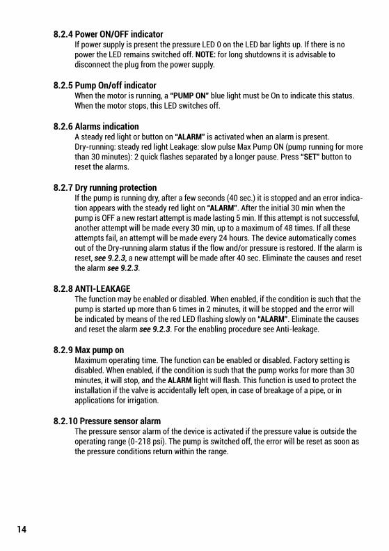
8.2.4 Power ON/OFF indicatorIf power supply is present the pressure LED 0 on the LED bar lights up. If there is no power the LED remains switched off. NOTE: for long shutdowns it is advisable todisconnect the plug from the power supply.
8.2.5 Pump On/off indicatorWhen the motor is running, a “PUMP ON” blue light must be On to indicate this status. When the motor stops, this LED switches off.
8.2.6 Alarms indicationA steady red light or button on “ALARM” is activated when an alarm is present.Dry-running: steady red light Leakage: slow pulse Max Pump ON (pump running for more than 30 minutes): 2 quick flashes separated by a longer pause. Press “SET” button to reset the alarms.
8.2.7 Dry running protectionIf the pump is running dry, after a few seconds (40 sec.) it is stopped and an error indica-tion appears with the steady red light on “ALARM”. After the initial 30 min when the pump is OFF a new restart attempt is made lasting 5 min. If this attempt is not successful, another attempt will be made every 30 min, up to a maximum of 48 times. If all these attempts fail, an attempt will be made every 24 hours. The device automatically comes out of the Dry-running alarm status if the flow and/or pressure is restored. If the alarm is reset, see 9.2.3, a new attempt will be made after 40 sec. Eliminate the causes and reset the alarm see 9.2.3.
8.2.8 ANTI-LEAKAGEThe function may be enabled or disabled. When enabled, if the condition is such that the pump is started up more than 6 times in 2 minutes, it will be stopped and the error will be indicated by means of the red LED flashing slowly on “ALARM”. Eliminate the causes and reset the alarm see 9.2.3. For the enabling procedure see Anti-leakage.
8.2.9 Max pump onMaximum operating time. The function can be enabled or disabled. Factory setting is disabled. When enabled, if the condition is such that the pump works for more than 30 minutes, it will stop, and the ALARM light will flash. This function is used to protect the installation if the valve is accidentally left open, in case of breakage of a pipe, or inapplications for irrigation.
8.2.10 Pressure sensor alarmThe pressure sensor alarm of the device is activated if the pressure value is outside the operating range (0-218 psi). The pump is switched off, the error will be reset as soon as the pressure conditions return within the range.
15
8.3 FIRST START UP
8.3.1 Test on LEDsWhen the device is started up the first time, or after the plug is inserted in the power socket, the Test is conducted on the 20 LEDs, for a few seconds during which all the LEDs will light up in sequence.
8.3.2 First primingThe pump will automatically be in AUTO mode set to ON.There may be three possible behaviors:
1) Flow present,but low pressure: exit priming phase and start normal operation. 2) Pressure present, but no flow: after 10 sec. the pump will switch itself off. 3) No flow and no pressure: the pump will switch itself off and the dry-running error will be displayed after about 3. minutes, indicated by the red LED in SET-ALARM. Eliminate the cause and reset the alarm see 9.2.3.
8.4 Normal operations with CUT-OUT disabled (factory setting)CUT-OUT disabled means the following behaviour is present:
• Pump is activated if there is flow or pressure is absent, pressure is less than CUT-IN (in 10 min). • Pump is stopped if the pressure is present but flow is absent continuously for 10 sec. CUT-OUT LED will be switched OFF during normal operation. To modify the setting see 9.1.1.B.
8.5 Normal operations with CUT-OUT enabled CUT-OUT enabled means the following behaviour is present:: • The pump is activated if the pressure is less than the CUT-IN pressure. • The pump is stopped if the pressure is higher than the CUT-OUT pressure. CUT-OUT LED will be switched ON during normal operation. To modify the setting see 9.1.1.B.
9. PRECAUTIONS RISK OF FREEZING: when the pump remains inactive at a temperature lower than 32º F, it is necessary to ensure that there is no water residue which could freeze causing cracks in the plastic parts. If the pump has been used with substances that tend to form deposits, or with water containing chlorine, rinse after use with a powerful water jet in order to avoid the formation of deposits or coatings which would reduce the performance of the pump.
10. MAINTENANCE AND CLEANING In normal operation the pump does not require any type of maintenance. In any case, all repair and maintenance work must be carried out only after having disconnected the pump from the power supply. When restarting the pump, ensure that the suction filter is always fitted so as not to create the risk or possibility of accidental contact with moving parts.
16
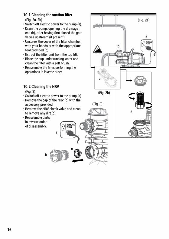
10.1 Cleaning the suction filter (Fig. 2a, 2b) • Switch off electric power to the pump (a). • Drain the pump, opening the drainage cap (b), after having first closed the gate valves upstream (if present). • Unscrew the cover of the filter chamber, with your hands or with the appropriate tool provided (c). • Extract the filter unit from the top (d). • Rinse the cup under running water and clean the filter with a soft brush. • Reassemble the filter, performing the operations in inverse order.
10.2 Cleaning the NRV (Fig. 3) • Switch off electric power to the pump (a). • Remove the cap of the NRV (b) with the accessory provided. • Remove the NRV check valve and clean to remove any dirt (c). • Reassemble parts in reverse order of disassembly.
(Fig. 2a)
(Fig. 2b)
(Fig. 3)
a
b
c
d
a
b
c
b c

17
11. TROUBLESHOOTINGDISCONNECT THE PUMP FROM THE POWER SUPPLY BEFORE TROUBLESHOOTING.If there is any damage to the power cable or pump, necessary repairs or replacements must beperformed by the manufacturer, authorized dealer, or by an equally-qualified party in order toprevent any risks.
ISSUE POSSIBLE CAUSES REMEDIES
The motor doesnot start ormake any noise.
A. Check the electric connections.B. Check that the motor is live.C. Check the protection fuses.D. Possible intervention of thermal protection.
A. Change any burnt out fuses.B. Wait about 20 mins until the motor cools. Check and eliminate the cause of intervention.NOTE: If the issue is repeated, the motor is short circuiting.
The motor does not start, but makes noise.
A. Ensure that the mains voltage is the same as the value on the plate.B. Look for possible blockages in the pump or motor.C. Check for blockage in the shaft.D. Check capacitor condition.
A. Remove any blockages.B. Use the tool provided to release shaft.
C. Replace the capacitor.
The motor turns with difficulty.
A. Check if voltage is sufficient.B. Check whether any moving parts are scraping against fixed parts.
A. Eliminate the cause of scraping.
The pump does not deliver.
A. Pump has been incorrectly primed.B. Diameter of intake pipe is insufficient.C. Clogged NRV valve or filter.
A. Fill pump with water and prime it, unscrew vent cap to release air.B. Replace the pipe with a larger diameter pipe.C. Clean the filter and NRV valve.
The pump does not prime.
A. Suction pipe is taking in air.B. Downward slope of intake pipe is causing formation of air pockets.
A. Eliminate the phenomenon, check if connections and suction pipe are airtight, then repeat the priming operation.B. Correct inclination of intake pipe.
The pump suppliesinsufficientflow.
A. The suction pipe is clogged.B. The impeller is worn or blocked.C. The diameter of the intake pipe is insufficient.
A. Clean the suction pipe.B. Remove the obstructions or replace the worn parts.C. Replace the pipe with a larger diameter pipe.
The pump vibratesand operates noisily.
A. Check that pump and pipes are firmly anchored.B. If there is cavitation in the pump, the amount for water is higher than pump is able to pump.C. The pump is running above its plate characteristics.
A. Fix the loose parts carefully.B. Reduce the intake height or check for load losses.C. It may be useful to limit the flow at delivery.

18
When purchased from an authorized Hawthorne dealer, this product is covered by a LIMITED WARRANTY available at hawthornegc.com/warranties. You can also obtain the Terms of Sale and Limited Warranty by calling Hawthorne toll free at 1-888-478-6544 or writing Hawthorne at: Hawthorne Hydroponics LLC, 3204 NW 38th Circle, Vancouver, WA 98660, Attn: Customer Service.
PRODUCT WARRANTY SCHEDULEPRODUCT WARRANTY PERIODElectric Multistage Pump - 727196 | 1416 GPH 2 year limited warrantyElectric Jet Pump - 727194 | 900 GPH 2 year limited warranty
LIMITED WARRANTY

19
NOTES

Manufactured for Hawthorne Hydroponics LLC, a subsidiary of The HawthorneGardening Company | 3204 NW 38th Circle, Vancouver, WA 98660 | ©2018
HawthorneGC.com | Canada: HawthorneGC.ca
NOTES
1219
18LM