garland likinsr frank rauscher and mohamad hussein · garland likinsr frank rauscher and mohamad...
TRANSCRIPT
---_._----_.
PILESBengt H,Fel1enius, Editor
Introduction to the Dynamics of Pile TestingGarland Likinsr Frank Rauscher and Mohamad HUssein
Piles are frequently required for a widerange of buildings, bridges, towers,dams,and other massive structures. Avz.riety of pile types installed by dif-ferent driving equipment of all typesand even layered soils makes estab-lishing a safe but economical installa-tion diITlcult. Traditionally, staticanalysis, probe piles, dynamic for-mulae, and SLatic testing are used toverify pile foundations. With com-puters and modem electronic measure-me:its, improved teChniques foranalysis and construction control arenow available to obtain a safe andeconomical solution.
BackgroundPile capacity may be estimated fTOmstatic analysis based on soil mechanicsprinciples and CPT and/or SIT fieldtests. Unfonunatejy. different soil test-ing and evaluation methods producewidely different solutions. I
Static testing involves the applica-tion and measurement of static loadsand pile movements. In practice, statictesting either proves the pile can safelyhold the service load (proof test). orestablishes an al10wable load based onthe capacity. Unfonunatdy, proof test-ing is mOre prevalent, reSUlting ingreater foundation Costs due to unneces-sarily long piles. Because of the rela-tively high costs and time required forstatic test, gener.::ll)' only a few piles aretested. Tne c.::pacity or failure defini-tion is also the subject of considerablediscussion and measu,ements Oftencon:ain substantial errors (Fel1enius,1980).
Forcenturies. engineers have tried toUSe dyn3mic formulae to estimatecapaCity. DynJJTlic for.nulae are inac-
Curate due to their over-simplicity inmodelling the hammer, driving system,pile. and soil. In fact, most foundationengineers tOday agree that dynamic for-mulae are dangerously unreliable.
Wave Equation Analysis of Piles(WEAP)Taking advantage of wave propagationtheories, in the 1950's, a discretenumerical solution with realistic ham-mer, pile and soil models was developed(Smith 1960) and became known as the"Wave Equation" to which various im-provements have been added (Gobleand Rausche, 1986). Based upon as-sumpt:ions of hammer efrlciency andsoil properties, the computerikd solu-
. .. ItlOn assumes a capacIty ana computes apenetration resistance (blow coum) andstresses, producing a SO-called bearinggraph_ Soil strength changes with time(set-up or relaxation) due to reroldingor pore pressure dissipation, s~ou1d beconsidered; at every site, so~efilesshould be restruck and the penetr tionres·istance reCorded. A1though the aveequation is an excellent tool, becausethe solution depends on assumptions,the only method to 2.$Sure accurateresullS is the measurement of hammerand/or pile perfoffilance during piledriving or during restrike to confmn theinput assumptions.
Dynamic MeasurementsPile hammers are complex devices. Ex.tensive srudies (Rausche er a/.. 1985b),show considerable scatter oi effiCiencyvalues for different hamme;s making
I -measurements a necessity Observa-tions of the ram t13ve1 during operation(SITo};e. blows per minute. etc.l) isrecommended. By detecting [he Sound
of and time berween nz.mmer blows. theSaximeter calculates the blows De.minute (or ram stroke for sinele actina
- bdiesel hammers). By employing radartechnOlogy, a Hamr';]er PerformanceAnalyzer can measure t.he ram velocitywith time (Likins, 1988).
The teChniques most widelyemployed Ioday for both measurementand analysis of piles were developed byProfessor G.G. Goble a: Case InsrirJteof Technology, hence collectively theCase Method (Rausche et a1., 1985a).Tne Case Method requires the measure-ment of pile force and veloci ty during ahammer blow. Reusable transducersare quickly attached to any pile type;driven, drilled shaft, or caisson. Thesedata are SUITlcienr for evaluating piiedriving stresses. pile in:egrity, hz.'Tlr:1erperformance, and pile capaciry. Ai Ithese closed-form solution resullS arecomputed in a fraction of a second foreach hammer blow by L1)ePile DrivingAnalyzer (FDA) in the field.
Capacity MethodsUsing wave propagation cheory and as-suming a uniform elastic pile, the CaseMethod Iot31 soil resis12.r;ce (R) activeduring pile driving can be calculated.Tnis total resistance. R. is the sum ofstatic. S. (displacemerlt de.:Jendent) Jnddynamic, D. (yelociry dq:;>e:ldent ) com-ponents. To extract the static resis[3nce.Ihe follOwing must be c2~ed ou,: (A)elimination of the dz.rnping COrr.poilenr:(8) correction for e2r!y unl03din~ ofshaft resistance; (C) rime de~endent soilstr::ngIh changes (i.e .. seI-up or rel2..'d'lion); and (D) no. 0, very small. pilepenetration will mobilize only a ponionof the [oL:l1resisL:lnce. Tne method :JndIhese considerations hJ"e tx::::n

planned programme of periodicdynamic monitoring to confirm consis-tent hammer performance Jnd soil con-ditions across the site. In particular,since the trend in recent years has beento higher capacity piles. When hammerproblems occur, early detection is criti-cal to the foundation quality.
On many Concrete pile projects. thepile shaft integrity is conflITT1ed usingLowS train Testing by a s~al1 hand.heldhammer (Rausche et ai., 1988). Tht;pile Integrity Tester™ hardware andSOftware, developed for this function,present results in both time and frequen-cy domain. Tnis method is simple andquick but only investigates shaft in-tegrity and is subject to some limita-tions. Tne test can be econOmicallyapplied to a large number of piles toestablish typical records, minimizemisinterpretations of single results, andassure good qUality Contro1.
Dynamic pile testing methods havebecome Widely aC::"'''Pted within the lastdecade and benefit all parties.associate<:lwith a pile project Since dynarnictest-ing with the PDA and CAPWAJl is sofleXible, engineers are creatively adapt-ing this technique to· their specificprojects. The engineer is presented withmuch more information to assist indesign and construction Control. T;leContractor obl1ins infor:nation on theperformance of his hammer systemwhich can be used to re<:luce driVingtime and lower his costs. Knowledge ofstresses and ~i1e integrity, can lead toprocedures to reduce damage.j Theowner is assJre<:l of a higher qillalityf d· . I .J I doun auon SInce more pl.es are teste .The faster dynlmic resting reducc:; con-Struction ti~e alnd is less e~,pensi ve thanstaric tests. Testing indicator piles ~ftenverifies adequate capaci ry at smallerpenetration depth for reduced time andcosr of the founaJation. If problems aredetected, they cJn be corrected early ina projecr at comparatively modest clostand reduce legal problems Or constnu1,c-(JOn cl3Jms.
Because of the lower COSt and ad I i-!iona1 information provided. d)'na1icpile testing has been rapidly gaini1gacceptance worldwide. Tne resear9hbegun in 1964 Il:d to [he formation Gf
thoroughly Covered (Rausche er al.,1985a).
CAPWAP is a further nume,ica1analysis methOd for confirming .thePDA Calculated pile capacity. To stanthe CAPWAP ar.alysis, a wave equationsoil model is assumed and entered wi ththe hammer model replaced by themeasured velocity. CAJlWAP then cal-culates the force necessary to induce theimposed velocity. If the computed andmeasured forces do not agree, the soilmodel is changed and the analysisrepeated (Rausche et al., 1972). Thisaltemative process is repeated until nofunher improve:nenr in ·the force matchcan be obtained. Results indicate thestatic soil resistance distribution,quakeand damping factors, and stresses alongthe pile shafL Tne CAPWAP analysisCan therefore be used to confirm !bewave equation soil assumptions.
Dynamic Pile TestingThe delays and expenses of static test-ing are leading reasons why dynamictesting is often requested as a replace- .ment for or supplement to static tests.Several piles can be tested per day, and
.. therefore dynamic testing is Very costeffective. As many soils changestrengrh with time, restriking the pileafter a waiting pe:-iod often results inmore economical founcations for pileswith set-up (capacity increase) orpreVents major problems due to relaxa-tion (capacity loss). "Refusal" driVingma Y underpredict the capacity (similaranalogy to static proof tests wirh smallmOvemenr only indicting that pan ofrhecapacity has been mobilized).Dynamic testing also provides extra in-fonmation on hammer performance,driving Stresses, and pile integrityWhich is not availabJe by static testingalone. The driving criterion is USUallyeSlab1ished v,-ith one panicular hammerbut can be extended to all t)'p::s of otherhammers, of the same make ordifferenr,by compa,ing capacity and transferredenergy results from the POll..
Most problems on a piling site aredue to the hammer system sin.:::e theinstalling equipment is also relied uponfor Conslruction contra/. Thl:refore. alllarger projects should h<lvc a well
P:k DynamiCs. L~c. In ! 972 to lu,develop and promoted the cqUlpr;-
and methOds. ThrOUgh extenSivefons of cducarior:. training. and St•.client SUPPOI1. ovc~ 200 PDA Uf1lts h.been placed into operation inCountries with about 2000 projebeing tested yearly. As engineers h~realized the benetlts, this has fuf1.'resulted in inclUSion in specificaticand codes of pracrice by man y agenc.ooverning oile testing.c .
SummaryStatic testing to failure is ideal to assestatic bearing capacity but is verv 0
pensive and time consuming. li~iti~;the numberofpiles tested. Wave Eou:tion is excellent for predictino ·ti-
t>dynamics of pile driving if assUmptiorare realistic. Dynarnic measuremen:and analysis Can verify these assum!=tions. On site, the Cz.se MethOd wirhPile Driving Analyze:- can calcUlate pi!
. capacity, monitor hammer performanc:'-and-pi1es stresses, and investigare pi):integrity. Because of their flexibilir;,and low cost, dynamic testing methodcmay be applied to a relatively large per-centage of the piles to CUtCosts. increasepile loads, or eliminate problems. TnePiJe Integrity Tester can evaluate shaftimeg:;ity of all piJes .::,a re2.Sona01e cost.
A well. Conceived 2.'1d prop::rly ex-ecuted testing prograrnme will give en-gineers, contractors. and Ownersconfidence in the behaviourofrhe foun-dation. Installation difrlculties will bedetected early in the project and cor-rected. Decisions and prod uCtion dJi l_
ing will be kept On schedule.minimizing delays, I.lnnecessary ·cost).and claims aiding the project [OII:Jrctimely compleLion to the s2.tisfJction orthe Owner. Dynamic pik resting hasbecome bOlh routine and widespread asspecifications and codes of praclic::recognize the v<llue of [his powe."iulteChnique.
References
Fellenius. B.H .. 1980. Tile An31ysis O!Results from ROutine Pile LOJdinf:Tests. Ground EnginC'"Erillg. Vol. 1':;.No.6. pp. 19.31.
Goble, G,G .. and Rausch::-. E. ! 9S(,.
W3V: EqL:arion Analysis of Pi]:Found3tions - WEAP86 FHWAContracr DTFH61-84-C-00100.
Likins, G. and Rausch:, F., 1988, Ham-mer Inspection Tools, T1l1fd Interna-tional Conference on.the Applicationof Stress Wave Theory on Piles,Editor B.H. Fellenius, BiTech Pub-lishers Ltd., Vancouver, pp. 659-667.
Rausche, F., Goble, G.G., and Likins,G.E., March 1985 (a), DynamicDetermination of Pile Capacity,ASCE Journal of Georechnical En-gineering, Vol. 111, No.3, pp. 367-383.
RaUSCh:. F., Goble, G.G .. and Likins,G.E. and Miner. R.. 1985 (b), TnePerfonnance of Pile Driving Sys-tems, FHWA Contract DTFH61-82-1-0J059.
Rausche, F., Likins, G.£., and Hussein,M., 1988, Pile Integrity Evaluationby Impact Methods, Tnird Interna-tional Conference on the Applicationof Stress Wave Theory on Piles,Editor B.H. Fellenius, BiTech Pub-lishers Ltd., Vancouver. pp. 44-55.
Rausche, F., Moses, F., and Goble,G.G., 1972, Soil Resistance Predic-tions from Pile Dynamics, ASCE,
JOlirnal of Soil Mechanics andFoundations, Vol. 98. SM9. P;::. 917.937.
Smith, E.A.L., 1960. Pile DriVingAnalysis by Wave Equation, ASCi:.Journal of Soil Mechanics andFoundations, SM, Vol. 86, pp. 36-61.
-------------------------------Garland Likins, Pile Dynamics, Inc.,
Cleveland, Ohio, USA
Frank Rausche and MoharnadHussein, Goble Rausche Likins andAssociates, Inc .. Cleveland. Ohio. {jSA.

GRL SOILVVare: ------.CAse Pile Wave Analysis Programs I
----..:CAPWAPCTM, P.I.T.WAPTM?,::;OGh:"f,1 ~!SiORY :"ND SACKCriOUND
In L1e 1218 1SOD's, un::::?, tiie sDonsorshiD at 1I1e OhioOepar.:7lenr ct Trans:::Or1a!icn, a program was develcped a!CaSB Institut8 cf iec,'":nolOgy in Cleveland, Ohio{l), whic.'1determined the Smith;:) soil resistance parameters from pilelOp measuremenlS. OriginaJly, a large computer automaticallySCNed :he proolem for relative!y sner1 piles.
CA.;:;n.,yA? de1ermines :''121set cf soil resis:anca patamet8r.3whic:l procuces a beS! male,., b8'tW8Bf1 measuffid andccmptrted pile rep forces and veloc,t)'. HalI1er t11an modelingand analyzing ,he hammer, one of the two measured curvesis LlSed as a pile top boundary ccndrtion.. TI1B complemernaryqUantiy is ccmpuled and comp2.Ied with !he appropriatemeasured curve. CA?WA? is J2.Sed on the premise that bestagreement ~rHeen measured and computed piIe top curvesis actlieved with a set of soil resistance parameters whichmaS( closely acprcxima:es the ac:ual soil behavior. The soilresistance moCel is repreSented by three parameter.;: ultima!eresistance, c;uake and damping. The program can be runimeraC:ively by the engineer or in a COmple1ely 21.10maticmOde. Obvicusly, as in alJ piie :eSLing, the resulting valuesreprssem ihe soii at It:8 lime of teSLing. Extensive correlationshave been maCe and repcned(J.<.Sl.
Features of :!le ,iSw CA?WAPC7}J, program which models the
pila wiLi CcntinuOL:s s.egi"7ien!s inc:ude: -• SI, r:-letric;, imporiaJ un~
• Ca~ Me1hod tMaring cap",6ty o=ed on ~ ckl .. "d form 3.Oi:"itcn• R.eo.idual Stre~ MMf3is• low S~n R..cord MatChing (P.L T.WAP)• P:::SWAP (Pile End s"aring WlSYtJ ArlaJy:.i3 Proc&eurei ~14to3
piie toe r"~" v:! pil<. to« movem<tf1'tfor and ~arin-;; pil""• wmprehenme numerical and (00/0() graphic. ot.'t:lu:• CAPwEAP, a wave ~uation an~~ ~in\l PCfe top
me~uremeno i~ead of a hamm&f mod",St.;rtlc load-s.<Jt curve ~ on the CAPHAPC r"~1t:3
• MatChing of fo~, Y"lo<:itie~ or upwan:b tr=&iin<; wav~
GRL effers CAP'NAPC ancJyS<3s.':::y its experienCed engi..-:eeG.H6weyer 'n..it11e program is comp~ble with the ;::lIe DrlvIngAnalyzer and may b€ acqUIred by PDA owners inexecutable form. tt requires the following h2.Icw2.Ie:
" IBM-PC, AT, 385 0( other ::omp.atiolo with gr"phi~, S4DK ~arn,Hard di!lk d1'ld on" floppy drive
" ~riaJ Port for HP74CO S-erie3 Plonor or c-:>mplUioie" Parallel Port (or primer (graphiC3 or l=<.r printor preierr<Ki)
Tna CA?WAPC Scftw2.Ie SyS!em inc:uces G?'LW:=AD (Naveequation of Pile Driving), ·G,~W ..1AG= ry¥a:ve equationDemonst,ator), DATPRO, P.LT.WAP and other [email protected] updates 2.I8 made available to ~ with c;,;rremsOftware support
CorrelatIon of ultim218 bearing C3pac,1y vcJues frc;m CA?'yV;.,pand lead tes~ based on the ~esearch wcli< a:r Case ir.s:;ilute atTechnology. ~ .,... _
~ i I~ u._ ~I ---------------- ___
~ ;~ ~--------------------------ua
REFE:=1ENCES:
I. GOble, G.G., Rausc:.e, F. and i,kse~, r., 'Cynamic St1Jdi~ on the 3eanng Ca;=lac~ of ?ile~, Phase ilr, SMSI'.lD, i'1eoor: No. ~, C.o..:;"Western Reserve Univer:i;y, 1S70.
2. Smith. S-\.L. 'Pile Driving Anaiysi~ :,y :.'1" Wave EqUation", Journal of Soif M=.'Jani= and FOUndation:;, ASC::' Aug~ 1960. ?p. 25-31.J. .'..iure. J.N.. :<ic;r.:!ey, ,\.1.:..., Gravare, C..J. and H"rmar.~Ofl, I.. "CAPWAP _ An =::onomic and Comorehensive A,~emetiv" :;J "r3Ci::jo,~aJ
.l,i~.'1oCsot Load .,e~,;,,; ~f ?iles'. Fiiing and Gr.;und Trearmenr FCJrFcundac·ons, ?a~r ~.s, Thoma:; "7' ~Hor::, London. 1S?.-J. ,::r 107. i 7".! .
.! i'iiva~a. S .. De ,.;. '\;';lrti,,~. JA. :::e !,jeceir03, C., Jr. and Lxin~, G.::', Jr., 'Oyna"71ic; Pile InstnJmef7t<ltion in 1l Caic;;.reous Sand C:c~ to pcr;.2?!a:;'Or7n, 3
ra:::!'. Ao;;fica~·on of St,-es.s·WaveJ ThEXJry on Pifes, Second lr;ter.:2.c·onaJ Conference, =::i1ec: ~y G. Holm. H. 3re::ier.:..ery, C.-J.Gravare. S"'eCis;, ?ile C.ommission, Stockholm, 1985. op . .J.J5-312.
5. SeiCel, J. and i'1ausche ::., 'Correlalion of Slaiic and Cynamic ,oile lests on !...arge Diameter DriIJed Shab', Appiication c.' S~=.W2'(eTn~ry, StOckholm 1SC5.;:>0.JI3-318.
Corr~lation cf CAPWA?C Com;Jl.J1ed and measur~ staticicac teSLCC1rves~:Cm a P~A and CAPWAPC dSmOnSLRiion a!the 1938 Or:i ann'-1ci C::::r.72:2ncein ,~alejgh, NC.
'.0.1 0 /)1"0 ~ I
"Xl
Goble Rausche Likins and Associates, Inc.Oaveiand 215-&31-<3131 D8fTYs( ~702(.''.1ain OHi::e) Phitadsiphia 215-S--g...27TO o r.a"l do
Se2171a4D7~9S292(-5- /TS-;:,,85
, CAPWAPCTM ~I
---JThe -::"pw;"pc PIle and SolI MadejThe C;"PW;"P Procedure
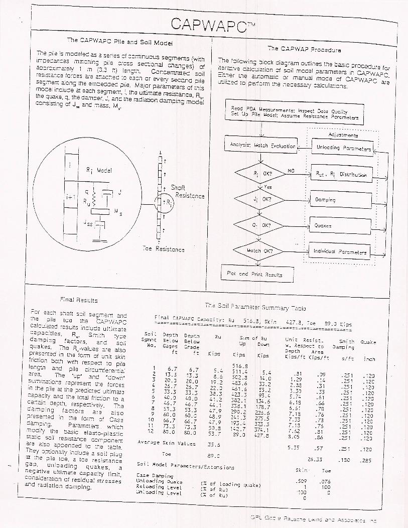
The ~iie is mcdelec as a series ct ::cr.tinuCt.!s segme-ms (withim;;ecanc:es mZ!::.'1ing :::ile cress secJonaJ c.'langes) ofac:::r::;:;iI71atety 1 m (3.3 ttl len;:,'l. Cvncsntra!ed soilres;s;anc:e forces are 2~act1ed :8 Bac.' or every sec~d pileseSiTlem along tile emceaaec ;:lils. Major param91ers cf thismCCel include at each segmem, i, the ultimate resistance, 1\"the quake. q, the darnper. J, and me radiation damping medelccnsis:ing cf J .. and m2SS, M"
R i Model
IR:~ If J
c=J MsI
Jss 171I
i~1
III
The f::llowins block diagrarTl oL.r.lines the basiC ~C<:Bd~r8 ferrterc::.ye CaJc:.;lation cf seil moeel parameters il: CAPwAPC=~,"ner L'le aU10matic or manual mods of c.:..?WA?C ar~,~;'I;--ri [0 "e.J--~ 'he ne"'''SS~''1 -"'cula'I·~ns~~ _=--- ,.. "1""'" ~- "". -~ .~.
Ke-:Jd FDA ~e-:J:surement:s; In=t Dolo QualitySet Up Pilei i.4o<Jel; Assume Re~~tonce Pcrcmeten
II ."'---- Adju:!tmef'lblAi1Civ>is: UGl:h E:voluation l :i UnkxJd:nq Pcr::m.eter:;l~
. I : l -1' -----,
NO
ShottResistance
Dcmping
/ ui
Toe Resistance individuci
................ - ..... ""
Plot and Print ReS'Jlb
Final Results
;=8r 22:;' shaH soil sec:~er.r ::nc:he pile toe tile CAPWA?CC2.lcu!arec rssutts include ultimateCapaCities, R
u' Sr.;i:h type
damping factors, and soilquakes. The R..,.values are aJsoprssemedin the fonm cf unit skinfriction both wrth respe;:c to pilelengtn and pile circumferemi2.lersa. The 'up"' and 'dC"Nn'sU"'r.:arions represem L'ls forcesin the ~ile at the predicte<:! ultimatec2.pac:ry and the Ictal fric;i:::m to acer;2in depth, respeC:-:iveiy. Thece.mping factors are alsopreser:;ed in tllS ferm cf C2Sed2.Inping. P2iarneters. whichmCd~ the C2Sic ela~~pl2.stlc~atic soil resistar.ce c:;mponemare 2.!so appended to tile table.They OP'jCrtally include a soil pluga:! ttle pile toe, 2. toe resis-:ancegap, unloading qual<;es, anega1ive ultlma1e C3pacity limit,consjderation of residt.;al Slressesc.nd radiation camping.
T:'l2 Soil ?3.ratn2ter S~rr;~2..ry ~2cie
:'27.3, Toe. 89.0 (i~~==================~=;==========================================Soi l Depth Depth R'.J SLI1! of <u Uni: Resis:. s.m i ::-:QlAli::eSs;:rnt 8elo« 8elolol Up DOlin 1-1. Respe-.:: to Oar.ni,~No. Gag e-s Grade
De,:Jch Areaft ft Ki;:>s (i;:>s Kips (i;:-slft (i?Slft slf: ire;'516.81 6.7 6.7 , ' 511. t, 5.4 .31 .09 .251 .120
,.~2 13.3 13.3 8.6 502.8 1~. a 1.29 " .251 .120. , ..3 20.0 20.0 19.2 .:...53.6 33.2 Z.3.5 .31 25' .120. ,t. 26.7 26.7 22.0 '-61.6 55.2 3.30 .35 .251 .1205 33 .3 33.3 38.3 ~23.3 93.t. 5.7:' .61 .251 .1206 '-D.O 40.0 4 i.2 2-02. 1 134 .6 6.18 .66 .251 .1207 '-6.7 '-6.7 :":'.1 338.1 1713.7 6.61 .70 .25 T .1208 53.3 53.3 47.9 290.2 226.6 7.18 .76 .251 .1209 W.O W.O t.8.9 2(.1.3 275 .5 7.33 .78 .251 .12010 66.7 66.7 :'7.9 193.(. 323.3 7.18 .76 .251 .12011 73.3 73.3 50.8 i~2.7 17:'.1 7.62 .81 .251 .12012 CO.O 3D.O c;- - 8>'.0 4zr·8 S.05 .s.s .251 .120
,.). I
Average $~in Values 35.5 5.35 .57 .251 .120Toe 89.0
26.33 .18-0 .2.';5Soi l Hcx:)"l ?ara'net::rs/::-':~.s iO<',s
$( i., ToeCase D~ir.g
. 5G-;l .076Llnlo~irl9 Du..l:e ( of lo.x:ing ~J:e) 1 100Re l O<)(j i ng levI!
, CAPWAPCIM ----jI
I
-J
CA?WA?C incl~des the residual stress analysis (RSA) feature,Soi l D~t:h Pi l e pi le Soi l Di spl.earlier introduced into GMl WEAP n... The calculation process
S9mt: Bel 0'0< Residt.;.al St:ress Resi=linvolves several eynamic trial analyses with imermediate static ~o. Gages Forces ror::escalculations which yield the state of equilibrium at the end d the a I::~ l::H 1=2 l::H "'"hammer blow. The thus compU1ed forces remaining in pile andPi le Top
3.101soil are presemed in both a table and bar graph (the ultimate soil
1 4.0 14.08 .13 -14.:;S 3.101resis:anca forces are also included for comparison).2 6.0 2(,.18 .31 -10. i0 3 ~-.""-..)3 8.0 2B.08 ,~ .36 -3.90 3.G'S'
... a......l .... lf~:. 10.0 30.52 .39 -2.4..:. 3.019
... '"5 12.0 t.D.56 .52 -10.04 2.9616 14.0 59.52 .76 -18.96 2_931
I I I7 16.0 78.57 1.00 -19.04 2.&57I 8 18.0 93.94 1.20 -15.38 2.76JJ'" I
I )) 20.0 111. (.2 1.(.2 -17_:..3 2.64.:.) I I I 10 22.0 13(..38 1.71 - 22. 96 2.5C611 24.0 161. 76 2.06 -27.38 2.~012 26.0 198.49 2.53 -36.:-3 2.14:1i3 28.0 220.10 2.30 -21.Q 1.~)It;....-r?~.l ~'r.~fa""t:rS
30.0 205.(.0 2.Q 14.7D 1.6.22I~
;-;-,. 01
15 3Z~O 161.98 2.06 'i . ...,1.3C.3"'t.,.,i. _~16 -, " 101.&5 1.30 6JJ. : 2 1.1&3
J.'o.u17 36.0 '-<1.23 .61 53.3 1 .0-'.2I I Toe
:"8.2..3""
Final Sumr.-:ary Plot
CCmOlI!ed and me2.St.;rcc ;cile lep forcesand/or velec;ty matches (ucper 1s1t)demons:;ar2 :he quality of ::;e final resutt.The simulated ~atlc test (I:::::wer [8ft) isCa.Jc:.;lcneCfrom pile anc scil STiffness andCAP\VA?C predicted Ru·values. The resuttingpile rap lead S81 CUNS may be comparedwith actcal static load teS1s.
f.J.cxima of compression i'.nC ter.sion forces and stresses, velocitIes, displacements and transferre(J energies err c. IimitE:dnumber of pCir;.s ere listed as pan of :he final OlItput. The table also contains absolute S1ress maxima including :,'1eir locaticnand time ct Occurrence.
The Resistance DistributIon Plot Oowerrigr.t) depic::; the final results underneathmeasured force and velocity (upper right)with :ime and lan:;th scales chosen such thatthe imoac: lime correspcnds to the pile tcpanc! :,"le pile toe reflecticn to the enc! bearing.
? j le De;:;:h max. mln. rr.ax. ;;'.ax. rr.ax .. max. i7;3X.
S;;7r) : bel 0'" Forc~ Forc~ Cooo. T~s ion :rnsfd. Veloc_ D is:Jl.No. Gages
Stress S:~ess Energym U~ 't:N (Ii! c:n2 r.1i!c;n2 1::>1 • m m/s =1.0 1821.3 -'-8.6 23 .21 .. S2 42.30 3.B 3.S013 3.0 1923.1 -56.8 Z'.50 .. /2 37.31 3.8 3.1507 7.0 1Q" - -98.7 23.'-8 '1.26 31.07 3.7 2.710
....-j . ..,)10 10.0 1829.1 -1'-8.7 Z3 .30 '1.39 28.02 3.6 2.390I~ 1~. CJ 1786.2 -190.1 22.7'S . Z.:'2 23.65 3.5 1.97'017 17.0 1665.1. -188.9 21.22 - 2.:' 1 19.21 3.~ 1.57'021 21.0 1569.S -183.6 19.99 '2.:'0 15.02 3.3 1.2'9025 25.0 1(.29.2 -151.0 18.21 ,1. ?2 11.19 3.0 .91.0
~
28 23.0 1323.0 -118.9 16.85 -1. 51 9.03 2.8 .iDO
-,32.0 1192.:' .0 15.19 .00 6.29 2.5 • :.,sc
.:.-35 35.0 956.3 .0 12.18 .00 , .29 2.6 .3:'036 36.0 9&5.5 .0 12.57 .:JO 3.1....: 2.5 .3C6,bsolu:~
'.02~ _50
(T= 3.5.1 os)L 20.0. Z.:Xl (T= 64.3 =)
,:;?~ ':;'::>e .~2L.'s':"·e !_rklns a:::j ....'..SS2:12:~ ,;-:::
I I I"---11. ..
ResIduaJ Force Graph and Table
The Ex1rema Table

./
Pile Variable Historle!l
The eX"-""pla CAPV'/A?C OL;~;Juts.,cws forcas and veloc;tiescc :"ree ::1itterer.; 10Cal:ons. Discla::amems, resistance fo~::asar;;:: :~ansf2rTed ener;;:es may 2.1so::l8 gracneC.
"'\\
! ~\...~
Simil3I to a corrYemior,aJ wave e<;'Jation, c,;PW~? procL:casa bearing graph relating ::leafing capac:ty aIle pile SUeSSBs toole ....coum. ine analysIs usai ~ CAPWAPC prediced statica'ld cynamic soil resls:a.nce i=2f3Inetar;;. ~'le ,'l3J7lmer isreplaCed by the me2,Sured pile !ap inpl.:t.o I I I I j ::::,:::-
~II I I
.Il c...c, ••
I I I I
\ I I I I I't,,-I I I I
- IIIU-1%11 I1 I I I 1
II 1 1 I I ..r I I J J I
, \....,/ .
'0'
-00
'00
- '0'1 .... 'CJ rt,
P.L T.WAP Alltoma!lc MOde
The fil.2.! resutt frcm P.l.T.WA? is the pile impecance as afunction of depth. These valc:es (typically every 2.50 mm or10 inc::esj rTK'!'j be a LIlomatIcally caJc'Ji21ed a.'1.er:.'1e engin~hc.s 2.S.3igne.j CBI-:2in seil resiS-~ca vacia:Jles. T;,a prog,c.r;oC:isclays :....:8 progrss.:> of adj~,errts as shCYIn :::.elow. Itinc:c2!es with a cur;;or the 100000cnswhere the a::justmen:sCJ8 being maCa in the c:.;rrerrt Cilalysis cyc:e .
P.1.T.WAP
This progr3J71 (related to CA?WA?C) mcnches pile top"eloc::ies based on low strain records (cb+.ained from 1heirncac: of " sm211 hanc-held hamGler). Program Options:~c::uce c2!c:...:iated and measured v8icc:ty vs Urns:;)'T~:J2.riso:1s and rast Fourier Transforms lea:::ing to ~he,'Icbiiity o~ Mechanical :"'cmi:-7ance c;f the pile.
...... 1.1.. _ .....
I..... I~l ..
'J
~··~l :'1
,..
,..'J
:: [1 ..1 AVI~~LIJsj ...~ ....... u_ u c..J - =T :....:t...:>- u....,.Eiilll'f'111 0 U :x:.w. ,-:..:s ::nD ='-' ,.....
""'",..
,..~. i"'_'~~
- ~L(\/ \
! \ .i ~_~~ .. ':"-~v.
Goble Rausche Likins and ASSOCiates) Inc,4535 ~fT.ery Industrial P2Ik'Nay
Cleveland, Ohio ~ 125 USA. 216-C:J1.o1312i6-C:Jl-D915