garlock - erikseriks.nl/documentatie/afdichtingen/asafdichtingen/garlock-ps-seal.pdf · ps-seal...
TRANSCRIPT

PS-SEAL Thermo-Elastic High-Performance Seals
Garlock
ISO 9002-94Cert. #001762
PS-SEAL - the shaft seal you‘re looking for
2
Content
General introduction . . . . . . . . . . . . . . . . . . . . . 2
Technical data . . . . . . . . . . . . . . . . . . . . . . . . . . 3+4
PS-SEAL Standard . . . . . . . . . . . . . . . . . . . . . . . 5
PS-SEAL Lip . . . . . . . . . . . . . . . . . . . . . . . . . . . . 6
PS-SEAL Special . . . . . . . . . . . . . . . . . . . . . . . . . 7
PS-SEAL Floating Seal Device . . . . . . . . . . . . . . 8
Assembly and installation instructions . . . . . . . 9
Application examples . . . . . . . . . . . . . . . . . . . . 10
Seals in the thermoelastic high-per-formance PS-SEAL series operatewith a sealing lip made from modi-fied PTFE. This material is producedusing a method specially developedby Garlock and marketed under thebrandname GYLON. Sealing lipsmade from GYLON have a particu-larly effective memory characteristic,are highly elastic and flexible, causevery low friction, thanks to their non-stickslip motion, suffer little wear andtear, and need no metallic springelement.
Garlock’s high-performance PS-SEALare specially designed for the task ofreliably sealing rotating shafts withhigh peripheral speeds, high pressureand temperature fluctuations, andaggressive media. In such demandingapplications conventional radial shaftseals with elastomer sealing lips areof only limited use or often no use atall. A seal in the thermo-elastic high-performance PS-SEAL series is thesensible alternative to mechanicalseals and packings. Use of Garlock’shigh-performance PS-SEAL offers inmany applications the ideal answerto your problem and really reliablesealing.
For over 25 years the PS-SEAL hasproven its value as a sealing element.The PS-SEAL is suitable for a widerange of applications, in the chemi-cals industry, process engineering,and general machine construction.
Here are just a few typical applications:
• centrifuge machinery• separators• rotating air compressors• mixers• agitators• spiral conveyors• rotary lead-throughs• pumps
The advantages of PS-SEAL are:
• suitable for applications underpressurized or vacuum conditions
• capable of handling highperipheral speeds
• suitable for a temperature range of- 60 °C to + 260 °C
• outstanding resistance to chemicalmedia
• can be used in the food and drinksindustry and in the pharmaceuticalsindustry
• good dry-running characteristics• low friction, and good resistance
to wear and tear.
Given the many different needs in-volved in practical applications,Garlock’s thermo-elastic high-perfor-mance PS-SEAL series is also theeconomical solution. Garlock offersusers four different product versions,ranging from the standard sealingring, available from stock and ready-to-install, right through to customizedspecial designs:
PS-SEAL Standard
PS-SEAL Lip
PS-SEAL Special
PS-SEAL Floating Seal Device

Technical data
3
Case material
Special material for applicationwhere improved chemical resis-tance is required.
Static sealing element
PS-SEAL Special
PS-SEAL Standard
Fluoroelastomer FKM
GYLON
Standard material
Special material for the pharma-ceutical industry and for the foodand drinks industry (carries FDAapproval)
Special material with good dry-run-ning characteristics and suitable forsoft counter-running surfaces
Materials for the sealing lip
GYLON-B
GYLON-W
GYLON-F
Standard material: Stainless steel 1.4571
Standard material: Stainless steel 1.4571
Standard material
Materials
GYLON, the basic material used for the sealing lips, isthe most significant reason for the success of the PS-SEALseries. Several variants of this sealing lip material areavailable. Suitable application-specific materials mustalso be selected for the case and for the static seal.
Unless specifically requested otherwise in the orderdocumentation, all seals in the PS-SEAL series are delivered in the standard materials.
Shaft surface
In order to achieve optimal hermeticity between the PS-SEAL and the shaft and ensure high functional reliability and a long useful life, the shaft should have the following surface roughness characteristics:
Ra = 0.10 - 0.40 µmRz = 0.65 - 2.50 µm R max = 4.00 µm
The shaft surface must have been processed without anynicks, gouges, or other surface defects which might leadto a leak. The surface hardness must be selected accor-ding to the pressure.
up to 1.5 bar minimum 45 HRCabove 1.5 bar minimum 60 HRC
For unusually exacting combinations (p x v) of over 20 bar x m/s we recommend a plasma coating withchromium oxide, ground without any nicks, gouges, or other surface defects, and PTFE-sealed.
Pressure/Vacuum
PS-SEAL Standard max. 10 barPS-SEAL Lip max. 25 barPS-SEAL Special max. 25 bar
For maximum pressure applications please check the p x v value. To this, please also see page 4 ”Applicationlimits“. The PS-SEAL is also recommended in applicationswith vacuum.
Operating temperatures
GYLON, the lip material used in the PS-SEAL series, hasa theoretical temperature range of - 90 °C to + 260 °C.However, when used in dynamic shaft seals, GYLON isof course subject a number of operating parametersbesides temperature, e.g. pressure and the shaft’srotational speed. These other parameters may reducethis maximum theoretical operating temperature range.
Technical data
4
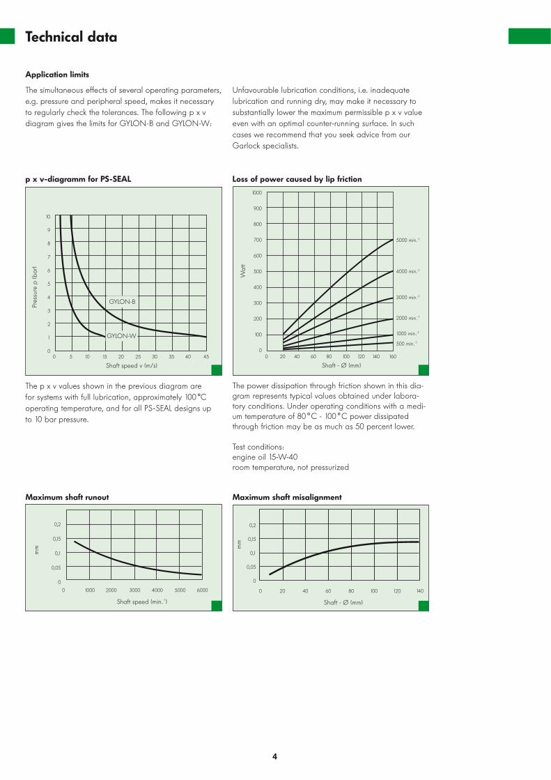
p x v-diagramm for PS-SEAL
The power dissipation through friction shown in this dia-gram represents typical values obtained under labora-tory conditions. Under operating conditions with a medi-um temperature of 80 °C - 100 °C power dissipatedthrough friction may be as much as 50 percent lower.
Test conditions: engine oil 15-W-40 room temperature, not pressurized
M tnemngilasim tfahs mumixaMtuonur tfahs mumixa
10
9
8
7
6
5
4
3
2
1
00 5 10 15 20 25 30 35 40 45
Shaft speed v (m/s)
Pres
sure
p (b
ar)
GYLON-W
GYLON-B
Loss of power caused by lip friction
0 20 40 60 80 100 120 140 160
Shaft - Ø (mm)
1000
900
800
700
600
500
400
300
200
100
0
Wat
t5000 min.-1
4000 min.-1
3000 min.-1
2000 min.-1
1000 min.-1
500 min.-1
0 1000 2000 3000 4000 5000 6000
Shaft speed (min.-1)
0,2
0,15
0,1
0,05
0
mm
0 20 40 60 80 100 120 140
Shaft - Ø (mm)
0,2
0,15
0,1
0,05
0
mm
Application limits
The simultaneous effects of several operating parameters,e.g. pressure and peripheral speed, makes it necessaryto regularly check the tolerances. The following p x vdiagram gives the limits for GYLON-B and GYLON-W:
The p x v values shown in the previous diagram are for systems with full lubrication, approximately 100 °Coperating temperature, and for all PS-SEAL designs up to 10 bar pressure.
Unfavourable lubrication conditions, i.e. inadequatelubrication and running dry, may make it necessary tosubstantially lower the maximum permissible p x v valueeven with an optimal counter-running surface. In suchcases we recommend that you seek advice from ourGarlock specialists.

PS-SEAL Standard
5
The PS-SEAL Standard is a ready-to-install radial sealingring with a stainless steel case and a sealing lip madefrom GYLON-B. Models with dimensions printed in thelist in bold face are available from stock and for modelswith dimensions not featured in the list we can make asuitable offer. If you need non-standard materials for thecase and/or the sealing lip, please contact us.
28
30
32
32
35
35
38
40
40
40
42
42
45
45
48
48
47
47
47
47
47
50
55
55
60
62
60
62
62
65
62
65
10
10
8
10
10
10
7
10
10
10
10
8
10
10
8
10
d1 d2 B
PS-SEAL Standard sizes
Stock sizes are indicated with bold type face.
50
50
50
55
55
60
60
62
65
70
70
73
75
75
80
PS-SEAL Standard sizes
R 0,5
Ra ≤ 2,0
20°
1,5 ± 0,2B +0,3
d 2H
8
d 1h1
1
GYLON-lip
Stat
ic s
ealin
g el
emen
t Stainlesssteelcases
80
85
90
90
95
100
100
105
110
110
115
120
125
130
135
140
110
110
110
120
120
120
130
130
130
140
140
150
150
160
170
165
10
12
10
12
12
12
13
12
12
13
12
12
12
12
12
10
65
70
72
72
80
75
80
80
85
90
95
100
95
100
100
10
10
10
10
8
8
10
10
10
10
10
10
13
10
10
d1 d2 B d1 d2 B
8
10
12
12
14
15
16
17
17
18
20
22
25
25
25
18
25
25
28
30
30
30
28
35
35
35
40
35
42
47
5
7
7
8
7
8
8
8
8
7
8
8
8
8
7
d1 d2 B
PS-SEAL Standard, special versions
Garlock PS-SEAL seals are also available in series dimen-sions but with different PS-SEAL lips and configurations.
Reserve lip Standard configurationwith dust lip
Double opposing lippressure/vacuum
Double Lippressure
PS-SEAL Lip
6
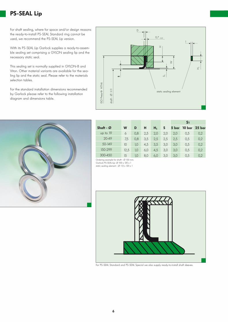
For shaft sealing, where for space and/or design reasonsthe ready-to-install PS-SEAL Standard ring cannot beused, we recommend the PS-SEAL Lip version.
With its PS-SEAL Lip Garlock supplies a ready-to-assem-ble sealing set comprising a GYLON sealing lip and thenecessary static seal.
This sealing set is normally supplied in GYLON-B andViton. Other material variants are available for the sea-ling lip and the static seal. Please refer to the materialsselection tables.
For the standard installation dimensions recommendedby Garlock please refer to the following installation diagram and dimensions table.
D
0,7 - 0,05
1
static sealing element
H1
W
S
shaf
t - Ø
h11
ISO
Pre
ss-fi
t H
7/r6
S 1
HOrdering example for shaft - Ø 100 mm:Garlock PS-SEAL-Lip- Ø 100 x 120 x 1static sealing element - Ø 113 x 120 x 1
W
6
7,5
10
12,5
15
D
0,8
0,8
1,0
1,0
1,0
H
2,5
3,5
4,5
6,0
8,0
H1
2,0
2,5
3,5
4,5
6,0
up to 19
20-49
50-149
150-299
300-450
Shaft - Ø S
2,0
2,5
3,0
3,0
3,0
5 bar
2,0
2,5
3,0
3,0
3,0
25 bar
0,2
0,2
0,2
0,2
0,2
10 bar
0,5
0,5
0,5
0,5
0,5
S1
For PS-SEAL Standard and PS-SEAL Special we also supply ready-to-install shaft sleeves.

PS-Seal Special
7
Since the range of possible applications for seals inGarlock’s thermo-elastic high-performance PS-SEALseries is so wide, the PS-SEAL Standard or PS-SEAL Lipversions may, for dimensional and/or application-specificreasons, not always represent the ideal solution.
In order to be able to offer customers an economicalanswer for such special situations, Garlock producesother single-lip and dual-lip variants in standardizeddimensions.
If you wish to use any of these PS-SEAL Special variantswe recommend that you seek advice from our Garlockspecialists.
PS-SEAL Special is available not only in the standardmaterials here listed but also in other material variants.
up to 1920-6465-119
120-199200-299300-450
Ordering example for shaft - Ø 100; 10 bar: Garlock PS-SEAL Special 100 x 128 x 10; 10 barOrdering example with O-ring:Garlock PS-SEAL Special - 100 x 130 x 10; 10 bar with O-ring
H8
11141517,520
H1
1012,515172025
Shaft - Ø B8
1010121520
5 bar2,22,53,03,03,03,0
25 bar0,20,20,20,20,20,2
10 bar0,50,50,50,50,5 0,5
Ordering example for shaft - Ø 100; 10 bar: Garlock PS-SEAL Special, double lip100 x 130 x 20; 10 bar with O-ring
Ordering example for shaft - Ø 100; 10 bar: Garlock PS-SEAL Special, double lip, pressure/vacuum100 x 130 x 17; 10 bar with O-ring
S1
PS-SEAL Special, single lip
H10
12,515172025
B141718202325
up to 1920-6465-119
120-199200-299300-450
Shaft - Ø B1
161920242630
5 bar2,22,53,03,03,03,0
25 bar0,20,20,20,20,20,2
10 bar0,50,50,50,50,50,5
S1
H10
12,515172025
B121517202425
up to 1920-6465-119
120-199200-299300-450
Shaft - Ø 5 bar2,22,53,03,03,03,0
25 bar0,20,20,20,20,20,2
10 bar0,50,50,50,50,5 0,5
S1
PS-SEAL Special, double lip
PS-SEAL Special, double lip pressure/vacuum
B + 0,2
Hou
sing
bore
- Ø
H7
Shaf
t - Ø
h11
HH
1
S 1
B + 0,2
B1+ 0,2
Hou
sing
bore
- Ø
H7
Shaf
t - Ø
h11
H
S 1S 1S 1
5 bar design
B + 0,2
Hou
sing
bore
- Ø
H7
Shaf
t - Ø
h11
H
S 1
10 and 25 bardesign

PS-SEAL Floating Seal Device
8
Garlock’s PS-SEAL Floating SealDevice is designed to provide acomplete solution to very individualproblems. This version can be usedin mixers and other similar machinesinvolving substantial excursion ordeflection in the shaft area to besealed. With conventional radialsealing rings or gland packings,shaft movement of this nature mightlead to immediate short-term failure.
The basic idea behind Garlock’s PS-SEAL Floating Seal Device is toseparate the sealing assembly onthe shaft from the fixed parts of thecase and to provide a permanentlyelastic connection between thesetwo elements.
All applications for which Garlock’sPS-SEAL Floating Seal Device mightbe used require individual consulta-tion and customized design and construction. You can contact us at Garlock at any time and withoutany obligation.
Flexible connector
Media
Seal housing withintegrated bearings
PS-SEAL Lip
All the information and recommendations provi-ded in this catalogue are based on our manyyears of experience and on state-of- the-arttechnology. However, the validity of thesegenerally applicable values may be restrictedby the influence of unknown variables. Binding
statements regarding the compatibility of ourproducts can only be made therefore afterpractical trials on the customer’s premises underrealistic operating conditions. Information provi-ded in our catalogues does not represent anattestation of any particular characteristrics.
All sizes in this catalogue are in mm.

Assembly and Installation Instructions
9
The sealing lip of seals in theGarlock PS-SEAL series must beinstalled without being damaged. It must never be mounted it oversharp edges.
When installing the GYLON sealinglip with its back to the shaft, auxiliaryradii or bevels must be used on theshaft end; (see Figure1). All edgesmust be chamfered, rounded, andpolished.
When installing the GYLON sealinglip towards the shaft end, an auxili-ary bevel of approximately 10 de-grees is required. This auxiliary bevelcan be placed directly on the shaftend. If, however, for structural rea-sons this is not possible, we recom-mend using a specially made moun-ting cone as an installation aid; (see Figure 2).
The use of the auxiliary bevel andexamples for the shape of the moun-ting cone are shown in Figure 2 andFigure 3. The surface of these instal-lation aids must be smooth and freefrom all nicks and gouges. All edgesmust be rounded off.
R min. 1and polished
Shaf
t - Ø
plu
s 0,
4
Shaf
t - Ø
min
us 5
10°
Shaf
t - Ø
plu
s 0,
4
Shaf
t - Ø
min
us 5
10°
Fig. 1
Fig. 2
Fig. 3

Application examples
10
PS-SEAL Special:Sealing a bearing
PS-SEAL Standard: Sealing ascrew-type compressor shaft
PS-SEAL Standard:Sealing a boring head
PS-SEAL Standard:Sealing a spiral conveyor shaft
PS-SEAL Lip: Sealing a pump assubstitute for gland packing
PS-SEAL Lip:Lip arrangement for overpressure or vacuum with a block
PS-SEAL Lip:Sealing a worm shaft bearing
Our staff are available for advice at any time,ensuring that your particular application isassigned exactly the right design. Take us atour word. Talk to us.

© M
its voorzien van duidelijke bronvermelding is overnam
e uit deze publicatie toegestaan. Alle rechten w
orden door ERIK
S nadrukkelijk voorbehouden. N
o part of this publication m
ay be reproduced
without clear reference to the source. A
ll rights expressly reserved by ERIK
S
ERIKS Servicecenters
AlkmaarSaffierstraat 31812 RM Alkmaar T +31 72 514 17 17F +31 72 514 16 25E [email protected]
AlmeloPlesmanweg 127602 PE AlmeloT +31 546 87 30 70 F +31 546 87 32 68 E [email protected]
AmsterdamDynamostraat 46-481014 BK AmsterdamT +31 20 448 96 10 F +31 20 613 77 65 E [email protected]
ArnhemPieter Calandweg 466827 BK Arnhem T +31 26 362 92 44F +31 26 361 00 63E [email protected]
Bergen op ZoomVan Konijnenburgweg 44 b4612 PL Bergen op Zoom T +31 164 27 55 44 F +31 164 27 55 49 E [email protected]
The HagueNeckar 2 2491 BD The Hague T +31 70 381 84 84F +31 70 381 84 36E [email protected]
DoetinchemHavenstraat 557005 AG DoetinchemT +31 314 34 37 20F +31 314 34 37 41E [email protected]
EerbeekLoubergweg 196961 EJ EerbeekT +31 313 67 95 00F +31 313 65 47 68E [email protected]
EindhovenDe Witbogt 22 a 5652 AG EindhovenT +31 40 291 19 00F +31 40 291 19 09E [email protected]
EmmenWillem Schoutenstraat 117825 VV EmmenT +31 591 66 80 00F +31 591 66 80 06E [email protected]
GroningenRouaanstraat 89723 CD GroningenT +31 50 368 49 99F +31 50 368 49 98E [email protected]
HengeloHassinkweg 16 7556 BV HengeloT +31 74 291 57 57F +31 74 291 59 39E [email protected]
HoornDe Factorij 35 d1689 AK ZwaagT +31 229 21 28 82F +31 229 21 93 74E [email protected]
LeeuwardenJames Wattstraat 19 8912 AS LeeuwardenT +31 58 215 05 87F +31 58 215 85 16E [email protected]
MaastrichtAmerikalaan 286199 AE MaastrichtT +31 43 604 91 80F +31 43 363 87 28E [email protected]
RoermondThomas Alva Edisonweg 56045 GN RoermondT +31 475 37 22 70F +31 475 37 23 05E [email protected]
Rotterdam-BotlekShannonweg 33 Haven 50793197 LG Rotterdam-BotlekT +31 10 231 34 00F +31 10 296 96 18E [email protected]
Rotterdam-NoordwestCaïrostraat 803047 BC RotterdamT +31 10 245 50 55F +31 10 262 00 38E [email protected]
TilburgEllen Pankhurststraat 95032 MD TilburgT +31 13 571 45 61F +31 13 570 06 42E [email protected]
ZwolleAmpèrestraat 278013 PT ZwolleT +31 38 467 29 20F +31 38 467 29 29E [email protected]
www.eriks.nl
ERIKS bv I Toermalijnstraat 5 I P.O. Box 280 I 1800 BK Alkmaar I T +31 72 514 18 55 I F +31 72 515 56 45 I E [email protected] I www.eriks.nl