gas and electric space heater mk ii sh2202 / sh2212b heater and 4 screws 1 space heater and 10...
TRANSCRIPT
Thank you for purchasing this Whale® product. For over 40 years Whale® has led the way in the design and manufacturer of freshwater and waste systems including:- plumbing, faucets, showers and pumps for low voltage applications. The company and its products havebuilt a reputation for quality, reliability and innovation backed up by excellent customer service. For information on our full product range visit: www.whalepumps.comCONTENTS1. Principles of Operation2. Specification3. Application4. Warnings5. Parts List6. Instructions for Installation7. Instructions for Use8. Maintenance9. Trouble Shooting10. Winterising11. Service Support Details12. EU Declaration of Conformity13. Patents and Trademarks14. Warranty15. Appendix A - Identifying Flue TypeLIST OF IMAGESFig. 1 Components drawingFig. 2 Installation in vehicleFig. 3 Installation under vehicleFig. 4 Dimensions – top view inside vehicleFig. 5 Dimensions – side view inside vehicleFig. 6 Dimensions – front view inside vehicleFig. 7 Dimensions – top view outside vehicleFig. 8 Dimensions – side view outside vehicleFig. 9 Dimensions – front view outside vehicle Fig. 10 Flue locating diagramFig. 11 Attaching fluesFig. 12 Heater locatingFig. 13 Installation and securing of heaterFig. 14 Floor construction and cut outFig. 15 Attaching under floor heaterFig. 16 Attaching fluesFig. 17 Secure flue bracketsFig. 18 Connect to gas supplyFig. 19 Connect gas supply to under floor heaterFig. 20 Hot air ductFig. 21 Hot air duct to under floor heaterFig. 22 Tee fitting orientation Fig. 23 Cold air ductFig. 24 Cold air duct to under floor heaterFig. 25 Insert control panelFig. 26 Secure control panelFig. 27 Installed control panel
Gas and Electric Space Heater Mk II SH2202 / SH2212B
1
INSTALLATION & USER INSTRUCTIONS
Fig. 28 Connect 12V connector Fig. 29 Connect 12V to interface plateFig. 30 Mains electrical connectionFig. 31 Mains connectionFig. 32 Completed installationFig. 33 Completed installation under vehicleFig. 34 Control panelFig. 35 Flue Type - for vehicle in motionFig. 36 Flue Type - for standard installation
The Whale® Space Heater Mk II is a gas and electric blown air space heater. Nominal heat output is 2kW on gasand 2kW on mains electric. When on electric mode, heat output is adjustable to low, medium and high settings withan automatically adjusting fan speed which minimises noise and current draw. The compact design provides versatili-ty in installation locations and needs minimal maintenance. The vehicle internal temperature is set by a room con-troller which can be manually adjusted to a wide range of temperature settings or to warm weather ventilation. Keyenhancements to the Mk II design are improved insulation, improved service access and lighter more compactdesign. Read the following carefully before installation
Model: SH2202 (inside vehicle) Maximum dimensions: Height: 230mm, Width: 157mm, Length: 634mm SH2212B (under-floor) Maximum dimensions: Height: 121mm, Width: 290mm, Length: 714mmCountries of Destination: AT, BE, BG, CH, CY, CZ, DE, DK, EE, ES, FI, FR, GB, GR, HU, HR, IE, IS, IT, LT, LU, LV,MT, NL, NO, PT, SE, SI, SK, TRWeight: Inside Vehicle Installation 7.7kg Under-floor Installation 7.7kgGas: Butane 28-30mbar - CAT I3+ (28-30/37), Butane/Propane 30mbar - CAT I3B/P (30)
Propane 37mbar - CAT I3p (37)
Gas Consumption (M) 150g/hClassification of Heater: Type: C53 (Fanned) Normal Installation
C13 Vehicle In Motion Installation
Nominal Heat Input: Gas 2.0kWNominal Heat Input Electric 2.0kW.Mains Electric:
Nominal voltage: 230V a.c. 50Hz Power options: 500/1000/2000WMaximum current a.c.: 9 Amps
Battery SupplyNominal voltage: 12V d.c. Operating range: 10.0V d.c. min. to 15V d.c. max. Maximum current d.c. gas operation: 1.7 Amps (0.01Amps on standby) Maximum current d.c. electric operation: 2.2 Amps (0.01Amps on standby)
Dry Storage Temperature: -20°C to 70°C Hot Air Duct Diameter: 60mm IDFlue Diameter: 22mm ID
2. SPECIFICATION
1. PRINCIPLES OF OPERATION
2
Maximum Exhaust Flue Length: 2m Minimum Exhaust Flue Length: 0.75m Maximum Combustion Air Flue Length: 2mMinimum Combustion Air Flue Length: 0.75mEnsure that the position allows access for servicing the Space Heater and that there is a minimum of 25mm distancearound the heater to adjacent walls when mounted inside the vehicle. Whale’s policy is one of continuous improvement and we reserve the right to change specifications without priornotice.
The Whale® Space Heater has been designed for caravan, motor home and mobile applications, and is more thanadequate for typical recreational vehicle use. The Whale® Space Heater is designed to be installed in conjunctionwith a ducted hot air system. If the heater is to be used in motion, the vehicle in motion kit must be fitted. This is anaccessory to the Whale® Space Heater and must be fitted to allow use in motion. Otherwise, do not operate theappliance while the vehicle is in motion. Please see Appendix A for information on identifying flue type. For moreinformation on this kit, contact Whale® Support.
This symbol indicates that this appliance is suitable for use in Leisure Accommodation Vehicles.
This symbol indicates that this appliance is not suitable for use in boats.
Observe all warnings.In the unlikely event of leaks in the gas system, or if there is a smell of gas:
• Extinguish all naked flames• Do not operate any electrical switches• Turn off all gas appliances • Open windows and doors for ventilation• Do not smoke• Shut off gas connection
Get the system thoroughly checked by a registered gas engineer at a Whale® Approved Service Centre / Technician. The space heater shall not be operated in the following situations:
• When refuelling the vehicle, the vehicle towing the caravan, or other appliances• When the vehicle in which the heater is installed is in motion; unless the vehicle in motion flue kit is
installed (please see Appendix A for information on identifying flue type)• When the vehicle in which the heater is installed is in a confined space such as a garage
3. APPLICATION
4. WARNINGS
3

This appliance is not intended for use by persons (including children) with reduced physical, sensory or mental capabilities, or lack of experience and knowledge, unless they have been given supervision or instruction concerninguse of the appliance by a person responsible for their safety. Children should be supervised to ensure that they donot play with the appliance. Ensure that a minimum of one of the hot air outlet vents is permanently open. This hot air vent should be the furthestfrom the Space Heater.Any alteration to the appliance, including flue components, use of non-Whale® spare parts/accessories and non-observation of the installation and operation instructions shall lead to cancellation of the warranty and exclusion of liability claims and results in it becoming illegal to use the appliance.Please note that incorrect installation, misuse or use of non original Whale® parts may invalidate the warranty. It alsobecomes illegal to use the appliance if incorrectly installed, and in some countries this even makes it illegal to usethe vehicle. When operating using gas, the combustion air inlet flue and outlet flue for the products of combustion (exhaust flue)shall never be obstructed. They should be checked regularly, and if necessary cleaned by the user (e.g. in winter,snow shall be removed from the combustion outlet and air intake).Where the open end of the exhaust flue terminates, three sides of the under-floor space are to be kept open and notobstructed, and not contain through floor ventilation openings. The heater, its gas supply, and flues for the products of combustion are to be inspected in accordance with nationalregulations or if these do not exist, the manufacturer’s recommendations, however, it is advised that this should bedone at least annually.Please note: The heater and ducts will become hot. Please avoid anything directly touching the heater orducts.
The Whale® Space Heater kit contains:
Please note that the Whale® Space Heater requires a separate flue kit for installation. Exhaust flues are available inlengths of 0.75m to 2m. A kit is also available specifically to allow the heater to be used while the vehicle is in motion.For a full list of flue kits available please contact Whale® Support.
5. PARTS LIST
4
SH2202 SH2212BSpace heater and 4 screws 1Space heater and 10 screws 1Control panel / Room thermostat and 4 screws 13.5m control panel cable (retail only) 1Warranty registration card 1 1Instruction manual including installation templates 1 1Instruction manual storage pocket, with adhesive fixing strip 1
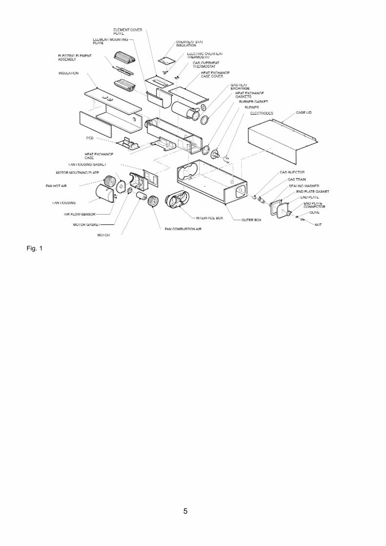
Fig. 1
5
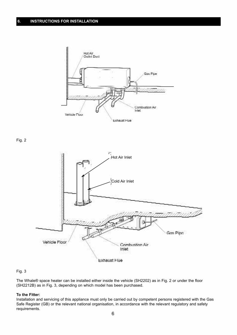
Fig. 2
Fig. 3 The Whale® space heater can be installed either inside the vehicle (SH2202) as in Fig. 2 or under the floor(SH2212B) as in Fig. 3, depending on which model has been purchased.To the Fitter:Installation and servicing of this appliance must only be carried out by competent persons registered with the GasSafe Register (GB) or the relevant national organisation, in accordance with the relevant regulatory and safetyrequirements.
6
6. INSTRUCTIONS FOR INSTALLATION
Cold Air Inlet
Hot Air Inlet
Before installation, ensure the appliance has been supplied in good condition and if damaged do not install. A competent person should install the appliance in accordance with the appliance installation instructions. This appliance is for use with LPG (see appliance data plate) and mains electricity (230V a.c.). Check that the product issuitable for the intended application, in particular the installer must check the compatibility of the data plate information with the LPG supply requirements of the vehicle. Follow these installation instructions and ensure all relevant personnel read the points listed below. Also ensure that these operating instructions are passed on to theend user. Please note: The appliance should be installed in accordance with any relevant regulations in the country where theappliance is installed. For this appliance in Europe the standard is BS EN 1949:2002 “Specification for the installationof LPG systems for habitation purposes in leisure accommodation vehicles and in other road vehicles”.Ventilation must comply with relevant national and/or local requirements.
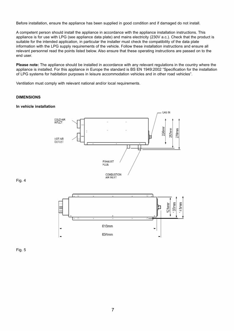
DIMENSIONSIn vehicle installation
Fig. 4
Fig. 5
7
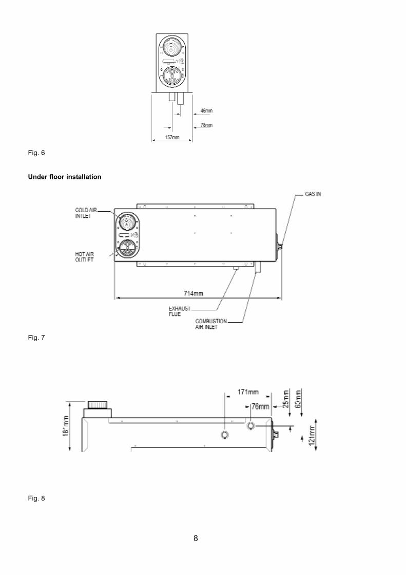
Fig. 6
Under floor installation
Fig. 7
Fig. 8
8
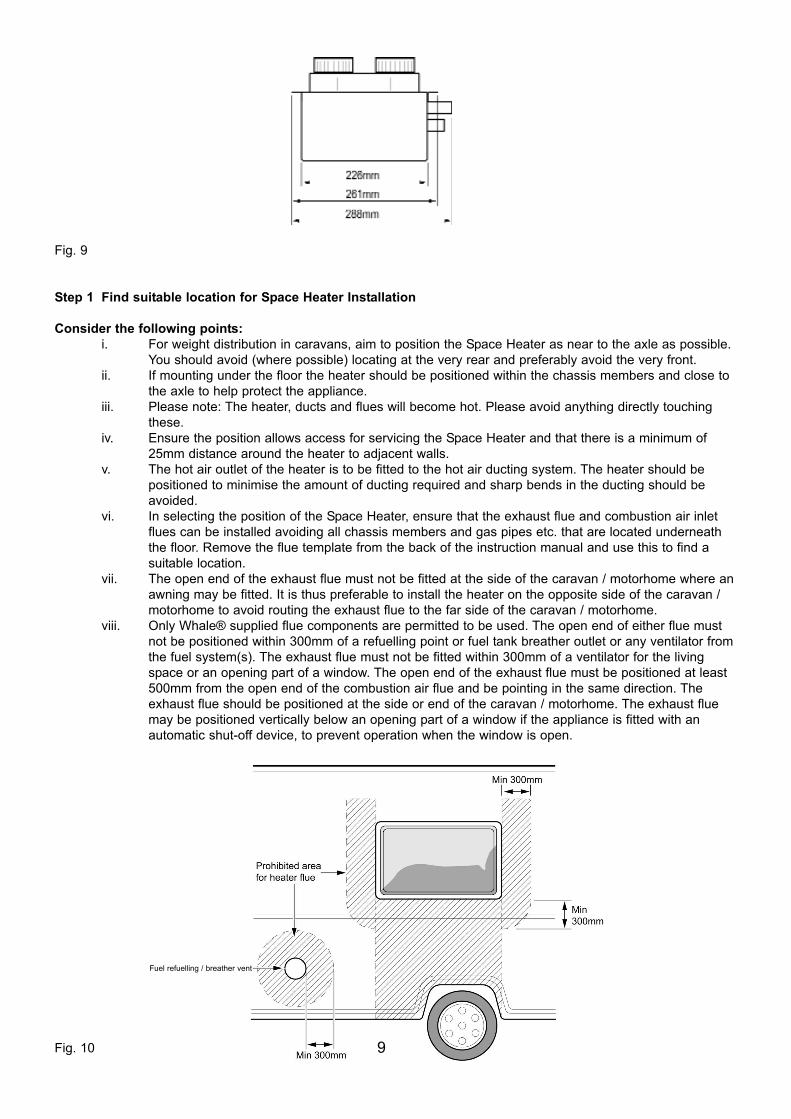
Fig. 9
Step 1 Find suitable location for Space Heater InstallationConsider the following points:
i. For weight distribution in caravans, aim to position the Space Heater as near to the axle as possible. You should avoid (where possible) locating at the very rear and preferably avoid the very front.
ii. If mounting under the floor the heater should be positioned within the chassis members and close to the axle to help protect the appliance.
iii. Please note: The heater, ducts and flues will become hot. Please avoid anything directly touching these.
iv. Ensure the position allows access for servicing the Space Heater and that there is a minimum of 25mm distance around the heater to adjacent walls.
v. The hot air outlet of the heater is to be fitted to the hot air ducting system. The heater should be positioned to minimise the amount of ducting required and sharp bends in the ducting should be avoided.
vi. In selecting the position of the Space Heater, ensure that the exhaust flue and combustion air inlet flues can be installed avoiding all chassis members and gas pipes etc. that are located underneath the floor. Remove the flue template from the back of the instruction manual and use this to find a suitable location.
vii. The open end of the exhaust flue must not be fitted at the side of the caravan / motorhome where anawning may be fitted. It is thus preferable to install the heater on the opposite side of the caravan / motorhome to avoid routing the exhaust flue to the far side of the caravan / motorhome.
viii. Only Whale® supplied flue components are permitted to be used. The open end of either flue must not be positioned within 300mm of a refuelling point or fuel tank breather outlet or any ventilator fromthe fuel system(s). The exhaust flue must not be fitted within 300mm of a ventilator for the living space or an opening part of a window. The open end of the exhaust flue must be positioned at least 500mm from the open end of the combustion air flue and be pointing in the same direction. The exhaust flue should be positioned at the side or end of the caravan / motorhome. The exhaust flue may be positioned vertically below an opening part of a window if the appliance is fitted with an automatic shut-off device, to prevent operation when the window is open.
Fig. 10 9
Fuel refuelling / breather vent

ix. The combustion air inlet flue can be terminated underneath the vehicle. The open end of it must be at least 500mm away from the open end of the exhaust flue, and pointing in the same direction. Takecare to ensure that both flues have a slight downward slope from as close to the heater as possible to prevent any possibility of water traps. Make sure neither the exhaust nor the combustion air inlet flues are terminated in an under-floor box section.
x. The minimum length of the exhaust flue is 0.75m, and maximum length 2m. The minimum length of the combustion air inlet flue inlet must be 0.75m, and maximum length 2m.
xi. When operating using gas, the combustion air inlet flue and outlet openings for the products of combustion (exhaust flue) must never be obstructed. They should be checked regularly, and if necessary cleaned by the user (e.g. in winter, snow shall be removed from the combustion outlet flueand combustion flue intake).
xii. Where the open end of the exhaust flue terminates, three sides of the under-floor space are to be kept open and not obstructed, and not contain through-floor ventilation openings.
xiii. The heater, its gas supply, ducting and flues are to be inspected in accordance with national regulations or if these do not exist, the manufacturer’s recommendations, however, it is advised that this should be done at least every year.
xiv. The heater must not be used when the vehicle is in motion unless the vehicle in motion flues and bracket are fitted. The vehicle in motion kit is not standard and is available separately. Please refer tothe vehicle in motion kit instruction for further fitting considerations or contact Whale® Support for more information.
If installing on the underside of the vehicle floor skip Steps 2 and 3.
Step 2 Cut out holes for exhaust and combustion air flues Position the template on the floor where the heater is to be mounted. Mark the position of the two holes for the combustion air inlet and exhaust flues, then drill holes with a 51mm (2”) minimum diameter hole saw.
Fig. 11Push on the ends of the flues with the blue adaptor to the pipes on the underside of the Space Heater ensuring theyare fully pushed on, and secure with supplied hose clips.
Fig.12
10

Step 3 Attach heater to the floor From inside the vehicle, feed the exhaust and combustion air flues through the holes drilled on the floor. Locate theheater so that the flues are centralised in the holes, and attach heater to floor with 4 screws supplied (No. 8 x ¾”), asper Figs. 12 & 13
Fig.13
Proceed to Step 6Step 4 Underfloor heater locationFor under-floor installation the floor of the vehicle should be manufactured as per the Fig. 14. It is important thatwooden batons are incorporated in the floors construction to allow the screws to secure into.
Fig. 14Locate the heater in the correct position such that the screws will enter the batons, and attached with 10 screws (No.8 x 5/8”) provided. Ensure that the mains cable is fed through the rectangular cut out and is not trapped between theouter cover box and the floor.
11

Fig. 15Step 5 Securing the flues
Fig. 16Push on the ends of the flues with the blue adaptor to the pipes on the underside of the Space Heater ensuring theyare fully pushed on, and secure with supplied hose clips.Step 6 Mounting the fluesWhen mounting the combustion inlet flue and exhaust flue, they should ideally run downwards from the heater totheir open end to allow any condensation to drain out. The open ends should be angled downwards to prevent rainfrom entering. Care should be taken to route exhaust flues around chassis members and avoiding gas pipes andwires. The flues should otherwise be kept as straight as possible.Please note: The exhaust flue should be positioned at the side or the rear end of the vehicle. The open end of thecombustion air flue must be at least 500mm away from the open end of the exhaust flue and pointing in the samedirection.
12

The combustion air inlet flue is attached to the underside of the floor with two of the brackets supplied. The remainingbrackets supplied with the flue kit are used to attach the exhaust flue. Clip the bracket around the flue and use twoscrews (No.8 x ¾”) to attach each bracket to the floor as per diagram, Fig.17.
Fig. 17
Step 7 Connect to gas supply
Fig. 18
13
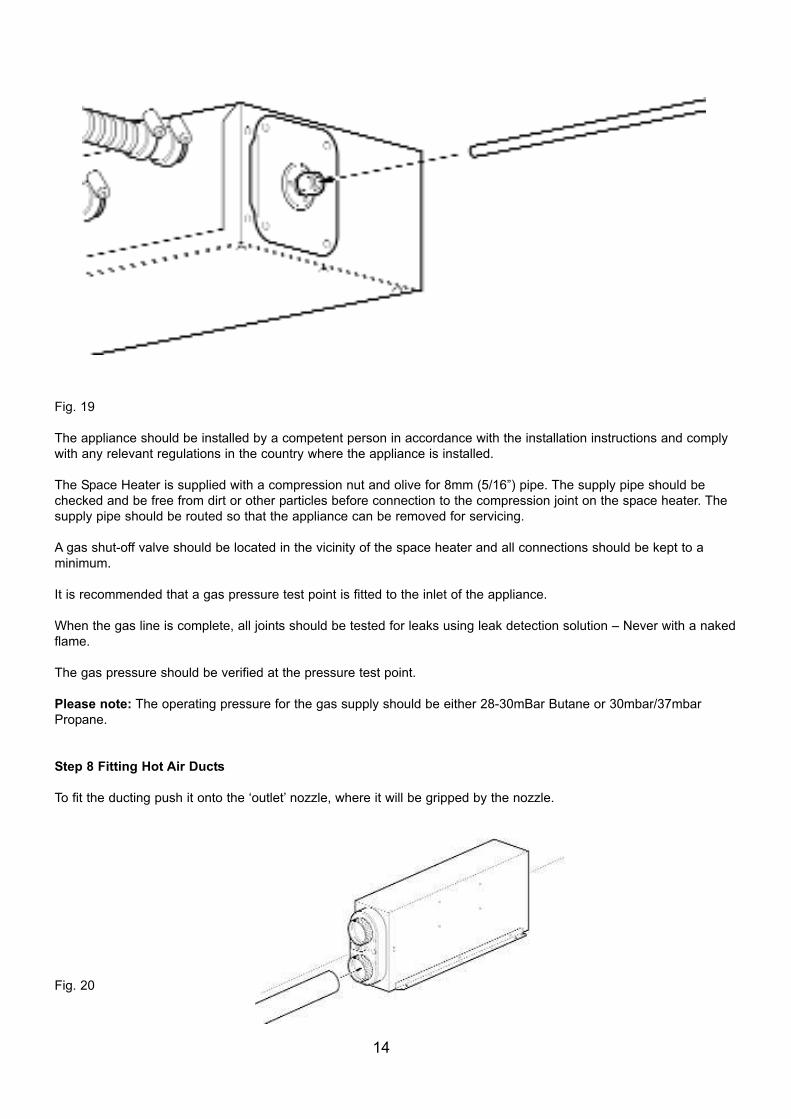
Fig. 19The appliance should be installed by a competent person in accordance with the installation instructions and complywith any relevant regulations in the country where the appliance is installed.The Space Heater is supplied with a compression nut and olive for 8mm (5/16”) pipe. The supply pipe should bechecked and be free from dirt or other particles before connection to the compression joint on the space heater. Thesupply pipe should be routed so that the appliance can be removed for servicing. A gas shut-off valve should be located in the vicinity of the space heater and all connections should be kept to a minimum.It is recommended that a gas pressure test point is fitted to the inlet of the appliance.When the gas line is complete, all joints should be tested for leaks using leak detection solution – Never with a nakedflame.The gas pressure should be verified at the pressure test point.Please note: The operating pressure for the gas supply should be either 28-30mBar Butane or 30mbar/37mbarPropane.
Step 8 Fitting Hot Air DuctsTo fit the ducting push it onto the ‘outlet’ nozzle, where it will be gripped by the nozzle.
Fig. 20
14

Fig. 21 If fitting an under floor heater, fit the air duct into the hot air outlet fitting. Important: At least one hot air outlet vent is to be permanently open. The hot air duct should not be fed into the centre branch of a Tee fitting as per Fig. 22.
Fig. 22
Step 9 Fitting Cold Air SupplyThe Whale® Space Heater must be adequately supplied with cold air. If the heater is installed in a bed box or another confined space, either vents into the area must be fitted or ducting used to supply the heater with cold air. Ifa vent is fitted, it must be no smaller than one designed for use with 60mm ducting. If ducting is fitted it should supplyair from the living space of the vehicle. To fit the ducting, push it onto the cold air inlet nozzle, where it will be grippedby the nozzle.
15

Fig. 23
Fig. 24
Step 10 Mounting of Whale® Control PanelWhen mounting the Whale® control panel, find a suitable convenient and accessible position. For good temperaturecontrol, select a position away from draughts and approximately 1.5m above the floor. Ensure suitable access forwiring loom connection and cable. Note that the cable supplied with the retail heater to connect the control panel tothe space heater is 3.5m long. The minimum depth behind panel for wiring must be 40mm. If using a control panelspecific to the manufacturer of the vehicle the electrical connections must be made in accordance with step 11.
16
Cold Air Intlet
Hot Air Outlet
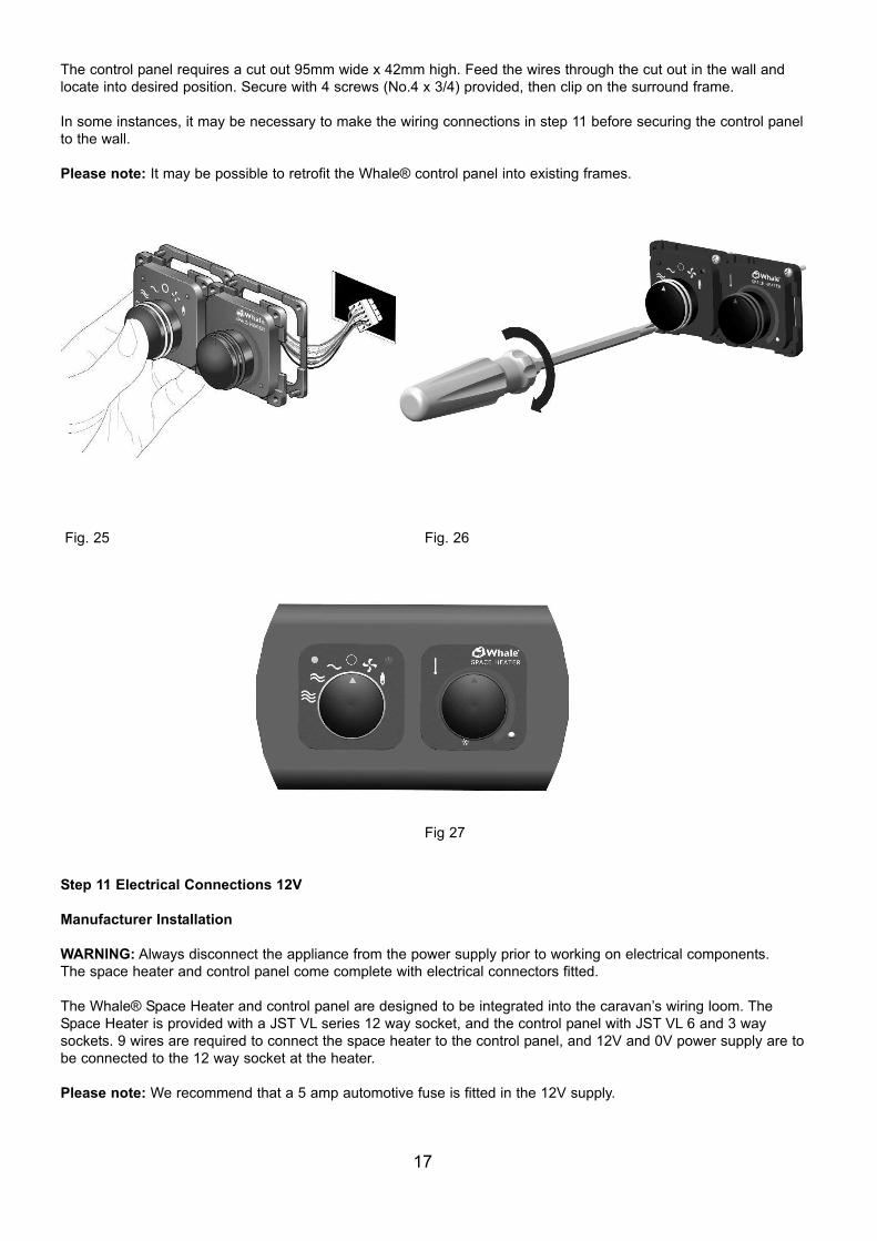
The control panel requires a cut out 95mm wide x 42mm high. Feed the wires through the cut out in the wall andlocate into desired position. Secure with 4 screws (No.4 x 3/4) provided, then clip on the surround frame.In some instances, it may be necessary to make the wiring connections in step 11 before securing the control panelto the wall. Please note: It may be possible to retrofit the Whale® control panel into existing frames.
Fig. 25 Fig. 26
Fig 27
Step 11 Electrical Connections 12VManufacturer InstallationWARNING: Always disconnect the appliance from the power supply prior to working on electrical components.The space heater and control panel come complete with electrical connectors fitted.The Whale® Space Heater and control panel are designed to be integrated into the caravan’s wiring loom. TheSpace Heater is provided with a JST VL series 12 way socket, and the control panel with JST VL 6 and 3 way sockets. 9 wires are required to connect the space heater to the control panel, and 12V and 0V power supply are tobe connected to the 12 way socket at the heater.Please note: We recommend that a 5 amp automotive fuse is fitted in the 12V supply.
17
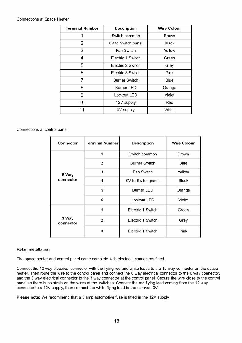
Connections at Space Heater
Connections at control panel
Retail installationThe space heater and control panel come complete with electrical connectors fitted.Connect the 12 way electrical connector with the flying red and white leads to the 12 way connector on the spaceheater. Then route the wire to the control panel and connect the 6 way electrical connector to the 6 way connector,and the 3 way electrical connector to the 3 way connector at the control panel. Secure the wire close to the controlpanel so there is no strain on the wires at the switches. Connect the red flying lead coming from the 12 way connector to a 12V supply, then connect the white flying lead to the caravan 0V. Please note: We recommend that a 5 amp automotive fuse is fitted in the 12V supply.
18
Terminal Number Description Wire Colour1 Switch common Brown2 0V to Switch panel Black3 Fan Switch Yellow4 Electric 1 Switch Green5 Electric 2 Switch Grey6 Electric 3 Switch Pink7 Burner Switch Blue8 Burner LED Orange9 Lockout LED Violet10 12V supply Red11 0V supply White
Connector Terminal Number Description Wire Colour
6 Way connector
1 Switch common Brown2 Burner Switch Blue3 Fan Switch Yellow4 0V to Switch panel Black5 Burner LED Orange
6 Lockout LED Violet
3 Way connector
1 Electric 1 Switch Green
2 Electric 1 Switch Grey
3 Electric 1 Switch Pink
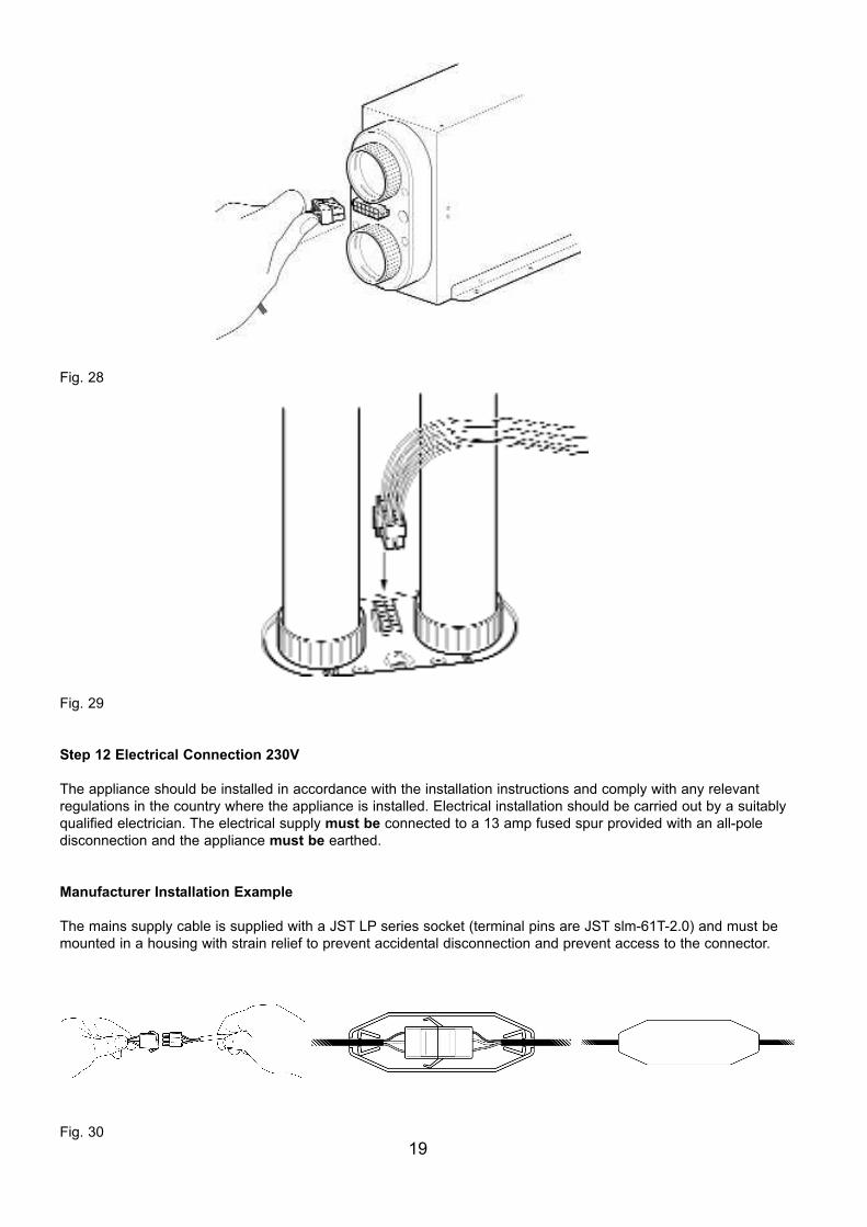
Fig. 28
Fig. 29
Step 12 Electrical Connection 230V The appliance should be installed in accordance with the installation instructions and comply with any relevant regulations in the country where the appliance is installed. Electrical installation should be carried out by a suitablyqualified electrician. The electrical supply must be connected to a 13 amp fused spur provided with an all-pole disconnection and the appliance must be earthed.
Manufacturer Installation ExampleThe mains supply cable is supplied with a JST LP series socket (terminal pins are JST slm-61T-2.0) and must bemounted in a housing with strain relief to prevent accidental disconnection and prevent access to the connector.
Fig. 3019
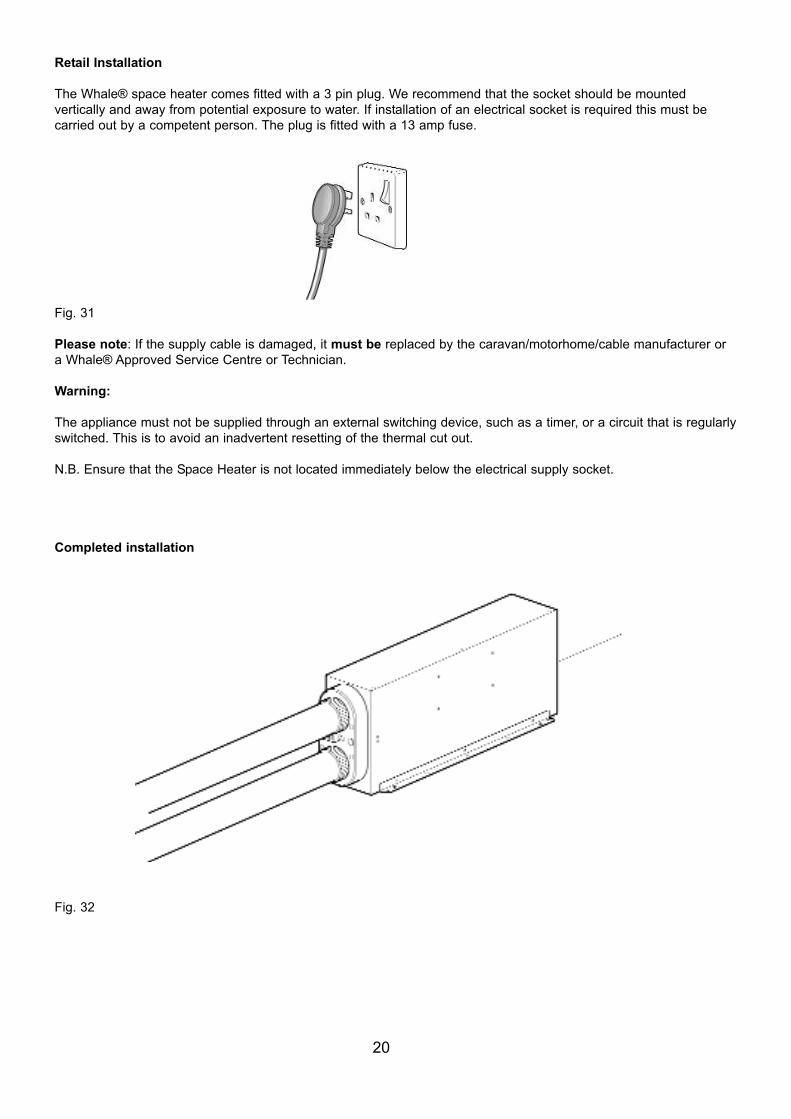
Retail InstallationThe Whale® space heater comes fitted with a 3 pin plug. We recommend that the socket should be mounted vertically and away from potential exposure to water. If installation of an electrical socket is required this must be carried out by a competent person. The plug is fitted with a 13 amp fuse.
Fig. 31Please note: If the supply cable is damaged, it must be replaced by the caravan/motorhome/cable manufacturer ora Whale® Approved Service Centre or Technician. Warning: The appliance must not be supplied through an external switching device, such as a timer, or a circuit that is regularlyswitched. This is to avoid an inadvertent resetting of the thermal cut out. N.B. Ensure that the Space Heater is not located immediately below the electrical supply socket.
Completed installation
Fig. 32
20
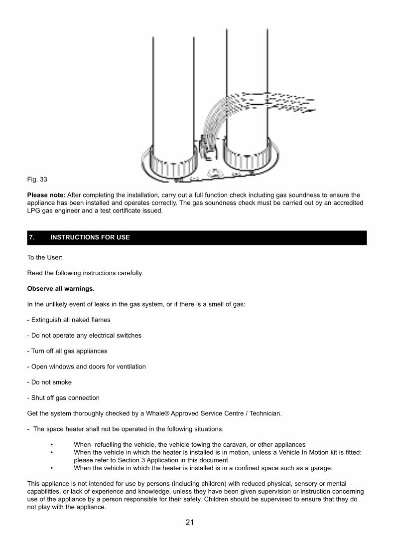
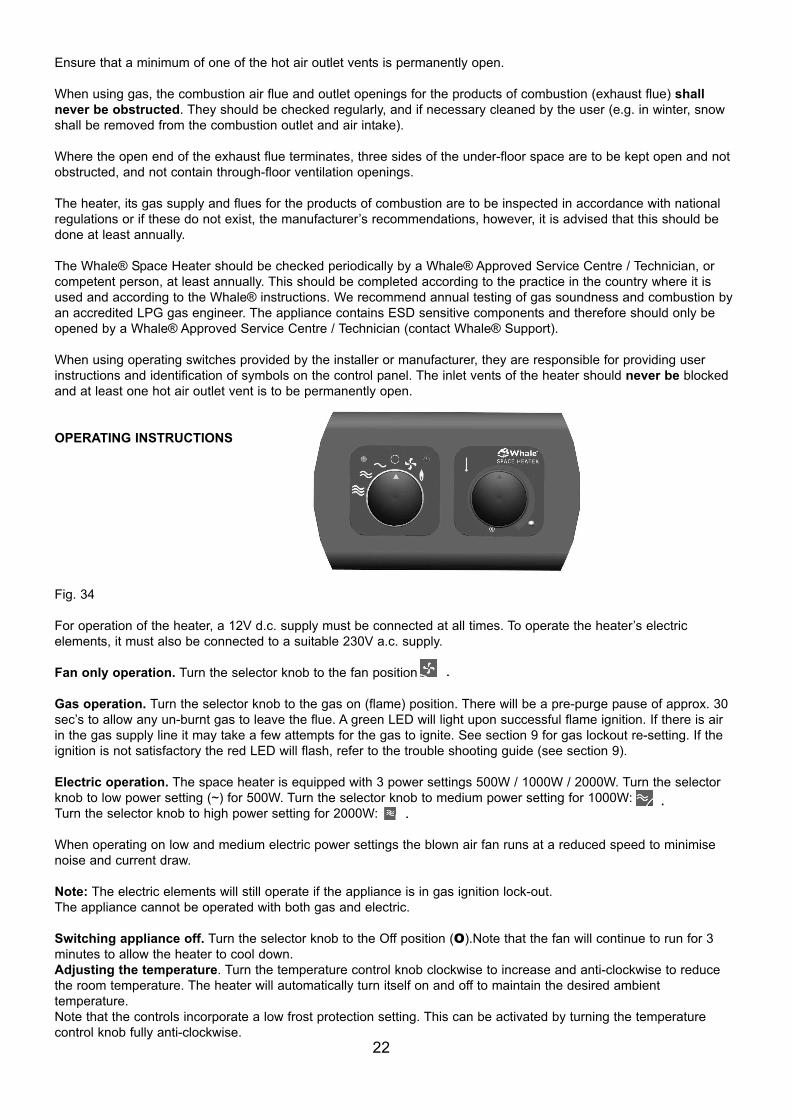
Fig. 33 Please note: After completing the installation, carry out a full function check including gas soundness to ensure theappliance has been installed and operates correctly. The gas soundness check must be carried out by an accreditedLPG gas engineer and a test certificate issued.
To the User:Read the following instructions carefully.Observe all warnings.In the unlikely event of leaks in the gas system, or if there is a smell of gas: - Extinguish all naked flames - Do not operate any electrical switches- Turn off all gas appliances - Open windows and doors for ventilation- Do not smoke- Shut off gas connectionGet the system thoroughly checked by a Whale® Approved Service Centre / Technician. - The space heater shall not be operated in the following situations:
• When refuelling the vehicle, the vehicle towing the caravan, or other appliances• When the vehicle in which the heater is installed is in motion, unless a Vehicle In Motion kit is fitted:
please refer to Section 3 Application in this document.• When the vehicle in which the heater is installed is in a confined space such as a garage.
This appliance is not intended for use by persons (including children) with reduced physical, sensory or mental capabilities, or lack of experience and knowledge, unless they have been given supervision or instruction concerninguse of the appliance by a person responsible for their safety. Children should be supervised to ensure that they donot play with the appliance.
21
7. INSTRUCTIONS FOR USE
Ensure that a minimum of one of the hot air outlet vents is permanently open. When using gas, the combustion air flue and outlet openings for the products of combustion (exhaust flue) shallnever be obstructed. They should be checked regularly, and if necessary cleaned by the user (e.g. in winter, snowshall be removed from the combustion outlet and air intake).Where the open end of the exhaust flue terminates, three sides of the under-floor space are to be kept open and notobstructed, and not contain through-floor ventilation openings. The heater, its gas supply and flues for the products of combustion are to be inspected in accordance with nationalregulations or if these do not exist, the manufacturer’s recommendations, however, it is advised that this should bedone at least annually.The Whale® Space Heater should be checked periodically by a Whale® Approved Service Centre / Technician, orcompetent person, at least annually. This should be completed according to the practice in the country where it isused and according to the Whale® instructions. We recommend annual testing of gas soundness and combustion byan accredited LPG gas engineer. The appliance contains ESD sensitive components and therefore should only beopened by a Whale® Approved Service Centre / Technician (contact Whale® Support).When using operating switches provided by the installer or manufacturer, they are responsible for providing userinstructions and identification of symbols on the control panel. The inlet vents of the heater should never be blockedand at least one hot air outlet vent is to be permanently open.
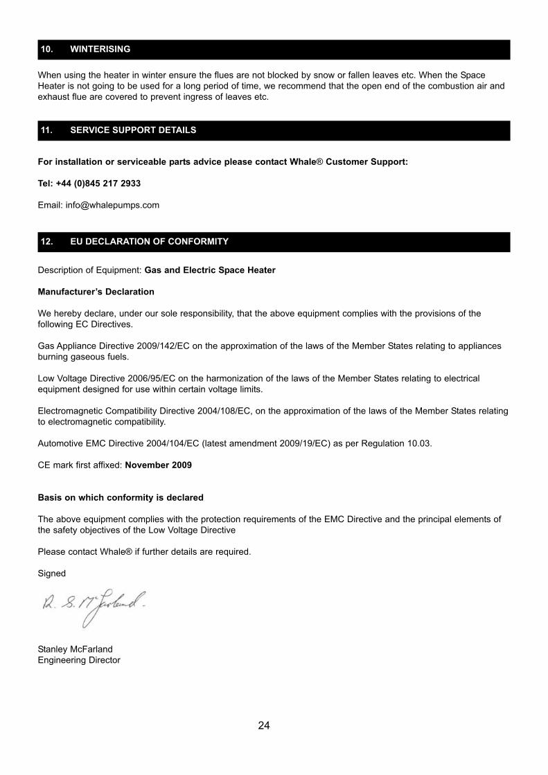
OPERATING INSTRUCTIONS
Fig. 34For operation of the heater, a 12V d.c. supply must be connected at all times. To operate the heater’s electric elements, it must also be connected to a suitable 230V a.c. supply. Fan only operation. Turn the selector knob to the fan position Gas operation. Turn the selector knob to the gas on (flame) position. There will be a pre-purge pause of approx. 30sec’s to allow any un-burnt gas to leave the flue. A green LED will light upon successful flame ignition. If there is airin the gas supply line it may take a few attempts for the gas to ignite. See section 9 for gas lockout re-setting. If theignition is not satisfactory the red LED will flash, refer to the trouble shooting guide (see section 9).Electric operation. The space heater is equipped with 3 power settings 500W / 1000W / 2000W. Turn the selectorknob to low power setting (~) for 500W. Turn the selector knob to medium power setting for 1000W: Turn the selector knob to high power setting for 2000W: When operating on low and medium electric power settings the blown air fan runs at a reduced speed to minimisenoise and current draw.Note: The electric elements will still operate if the appliance is in gas ignition lock-out.The appliance cannot be operated with both gas and electric. Switching appliance off. Turn the selector knob to the Off position (O).Note that the fan will continue to run for 3minutes to allow the heater to cool down.Adjusting the temperature. Turn the temperature control knob clockwise to increase and anti-clockwise to reducethe room temperature. The heater will automatically turn itself on and off to maintain the desired ambient temperature.Note that the controls incorporate a low frost protection setting. This can be activated by turning the temperature control knob fully anti-clockwise.
22
.
. .

If the heater has not been used for some time, dust may have settled inside the heater and the ducting. Run theheater on the “Fan only” setting until it clears. The outside of the appliance should not normally require cleaning. If itdoes, isolate the electrical supplies and wipe down with a soft, damp cloth only. Allow to fully dry before reconnectingthe electrical supplies.The Whale® Space Heater should be checked periodically by a Whale® Approved Service Centre / Technician, or competent person, at least annually. This should be completed according to the practice in the country where it isused and according to the Whale® instructions. We recommend annual testing of gas soundness and combustion byan accredited LPG gas engineer. The appliance contains ESD sensitive components and therefore should only beopened a Whale® Approved Service Centre / Technician (contact Whale® Suport).
The heater is equipped with an electronic diagnostic system which will detect fault conditions ranging from poor gasor d.c. supply to internal heater malfunctions. In the unlikely event of a failure, the red light on the control panel willflash a number of times, pause, and repeat until switched off. Count the number of flashes and refer to the tablebelow.
Gas LockoutsGas lockouts must be cleared by turning the selector knob from gas on (flame) position to off position then back tothe on position. The complete sequence of switch movements must be completed within 2.5 seconds for a lockout tobe successfully cleared. If there is air in the gas line, e.g. after a gas bottle change, the space heater may requireseveral attempts before it lights. Lockouts can also be cleared by switching to the ‘fan only’ position and then back to‘on’ within this 2.5 second period.Other LockoutsIf the lockout is caused when the unit is operated on electric, the lockout can be cleared by turning the selector knobfrom electric ‘on’ position to ‘off’ position then back to the ‘on’ position. The complete sequence of switch movementsmust be completed within 2.5 seconds for a lockout to be successfully cleared.Note: A cycling of the power supply to the unit will not clear a lockout. Some gas lockouts, e.g. ignition lockout andcombustion air faults will still permit use of the appliance in electric only operation.If the problem persists contact Whale Support on +44 (0)845 217 2933
23
8. MAINTENANCE
9. TROUBLE SHOOTING
Number of flashes Fault Remedy
1 No flame detected
2 Overheat
3 Low/high supply voltage
4 Combustion air fault
5 Other / internal fault
Check gas supply making sure there is gas in the bottle and no blockage inthe gas line. Ensure propane is used at temperatures below +5°C. Clearlockout as described below.
Minimum operating voltage is 10V, maximum is 15V, when measured at theheater. Check battery voltage. If between 10V and 15V, check connectionsbetween heater and battery. Check alternator or external battery charging.Clear lockout as described below.
Check the air ducts and vents are not blocked or restricted. We recommendyou wait at least 5 to 10 minutes to allow the heater to cool before clearinglockout as described below.
Check combustion air inlet flue and exhaust flue for blockages.
Attempt to clear lockout as shown below. If this fails, contact a WhaleApproved Service Centre / Technician.
When using the heater in winter ensure the flues are not blocked by snow or fallen leaves etc. When the SpaceHeater is not going to be used for a long period of time, we recommend that the open end of the combustion air andexhaust flue are covered to prevent ingress of leaves etc.
For installation or serviceable parts advice please contact Whale® Customer Support:Tel: +44 (0)845 217 2933Email: [email protected]
Description of Equipment: Gas and Electric Space HeaterManufacturer’s DeclarationWe hereby declare, under our sole responsibility, that the above equipment complies with the provisions of the following EC Directives.Gas Appliance Directive 2009/142/EC on the approximation of the laws of the Member States relating to appliancesburning gaseous fuels. Low Voltage Directive 2006/95/EC on the harmonization of the laws of the Member States relating to electrical equipment designed for use within certain voltage limits.Electromagnetic Compatibility Directive 2004/108/EC, on the approximation of the laws of the Member States relatingto electromagnetic compatibility.Automotive EMC Directive 2004/104/EC (latest amendment 2009/19/EC) as per Regulation 10.03.CE mark first affixed: November 2009
Basis on which conformity is declaredThe above equipment complies with the protection requirements of the EMC Directive and the principal elements ofthe safety objectives of the Low Voltage DirectivePlease contact Whale® if further details are required. Signed
Stanley McFarlandEngineering Director
24
10. WINTERISING
11. SERVICE SUPPORT DETAILS
12. EU DECLARATION OF CONFORMITY
The Whale® Space Heater is protected by the following patent and design registration applications:UK Patent application number: 0902533.9 & 0915825.4Whale® is a registered trademark of Munster Simms Engineering Ltd (also trading as Whale®).
The Whale® Space Heater is covered by a 3 year warranty. Please complete the enclosed warranty card and return to Whale.For warranty details, please see the enclosed warranty statement. Munster Simms Engineering Ltd.Old Belfast Road, Bangor, N. Ireland BT19 1LT Tel: +44 (0)28 9127 0531Fax: +44 (0)28 9146 6421www.whalepumps.comEmail: [email protected]
25
13. PATENTS AND TRADEMARKS
14. WARRANTY
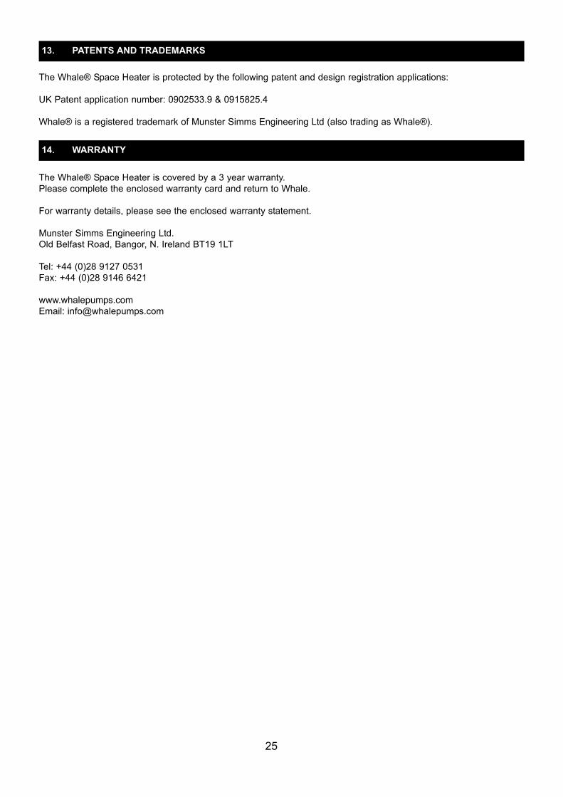
See below for identification of the flue type and installation.C13 Flue Type – for Vehicle in MotionThe C13 type utilises the Vehicle in Motion Double Flue Bracket, whereby both flues exit the vehicle wall via thesame bracket, with one flue located above the other (see below). For reference, the Exhaust Flue should always belocated above the Inlet Flue.
Fig. 35
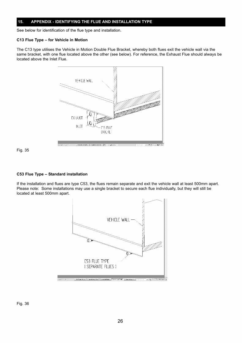
C53 Flue Type – Standard installationIf the installation and flues are type C53, the flues remain separate and exit the vehicle wall at least 500mm apart.Please note: Some installations may use a single bracket to secure each flue individually, but they will still be located at least 500mm apart.
Fig. 36
26
15. APPENDIX - IDENTIFYING THE FLUE AND INSTALLATION TYPE


Ref: 181.175_v1_0611