gas blower - le réseau Яé · pdf filebefore programming the eurotherm 902 check...
TRANSCRIPT

Cyberstar S.A. Siège social : Parc Sud Galaxie - 1 rue des tropiques - BP 344 - 38435 Echirolles cedex - France Tél : (33) 4.76.40.35.91 - Facs.: (33) 4.76.40.39.26.
Cyberstar S.A. au capital de 250 000 Euros - RCS Grenoble B 338 222 060 - 338 222 060 RM 381 siret 338 222 060 00026 - APE 333Z - nr tva FR 20 338222060
GAS BLOWER
User manual
April 2004

2/16
CONTENTS
page TECHNICAL INFORMATIONS 3 SAFETY RULES 4 PRACTICAL ADVICES 5 INSTALLATION 6 USER MANUAL 8 REGULATION PARAMETERS 13 GAS FLOW METER 14 CALIBRATION 15

3/16
TECHNICAL INFORMATIONS • Control unit Dimensions: L=550 mm, l=450 mm, h=270 mm • Gas blower Diameter=50 mm Height=80 mm Weight=680 g Materials: inox, aluminium, alumina and alumina fibers Power : 220 V - 1000 W (fuse 10A) Gas supply : 6 bars, 600 l/h maximum flow Water cooling supply : maximum 6 bars, water flow 30 l/h minimum, inlet temperature 25 °C. Features and limits • Maximum temperature : 1000 °C with a gas flow set to 500 l/h (air). • Repeatibility in the isotherm zone : ≤ ± 2°C • Stability during temperature dwell : ± 0.5°C • The sample temperature corresponding to the setpoint temperature must be defined by a calibration. The calibration must take into account:
- the emissivity of the sample - the geometry - the position in the flux - the gas flow

4/16
SAFETY RULES Do not use hydrogen or any toxic gas. Watch out for fire risks. The use of the gas blower in a closed room increases the fire risk as it increases the oxygen content. This device is hazardous, it can burn people or put fire to objects even away. The hazardous zone is set along the axis of the gas blower on a distance of 500 mm and a diameter of 150 mm. For example never put any X-ray detector along the axis of the gas blower. The water flow meter must be compulsory connected to the water circuit. In case of water leak or low water flow it switches off the power supply of the heating element and switches off the Eurotherm 902P temperature controller. Suitable gas above 1000°C are air, argon and oxygen. Never use nitrogen above 500 °C.

5/16
PRACTICAL ADVICES This device is meant to be set on 4 circle diffractometer with a spherical sample of up to 0.3 mm in diameter. The sample can be set very close to the output of the gas blower, the maximum distance being 3.5 mm. The drawing bellows shows a typical setting of the sample. In order to avoid "over-shooting" when changing the temperature setpoint it is best to use the "program mode" of the Eurotherm 902 temperature controller. Let increase the temperature slowly (<10 °C/minute). High temperature performance is dependant on the gas flow. At low rates the temperature at the sample position can be influenced by air draughts deflecting the gas stream. Under certain conditions an excessive flow can make the sample vibrating. Increasing the flow of gas reduces the radial isothermal plateau and increases the isothermal area in the axial direction.
gas blower SiO2 rod or tube
sample ~0.2 mm diameter glued with e.g. VISHAY micromesures GA100
2.5 mm

6/16
INSTALLATION • Before connecting or disconnecting any element of this equipment, always check that the control cabinet is switched off.
On the rear rack panel, connect C5 (thermocouple), C2 (heating element power supply). C7 is the RS232 connector. Connect the gas supply to the filter on the rear rack panel under the mention "GAS INLET". Pressure must be 6 bars oil free. The gas tubing must be 4 mm internal diameter and 6 mm external diameter. Connect the rack to a 230 V - 50Hz mains socket minimum power 1KVA using the standard cable. Connect the gas blower to a 4 bars water cooling system, minimum flow is 1 l/mn. Mentions “WATER INLET" and “WATER OUTLET” are set on the rear rack panel. A water safety device is connected into the water cooling circuit between the gas blower and the water outlet.

7/16
On the gas blower, connect the thermocouple connector, the gas fitting, the water fittings and the small Jaeger connector
8/16
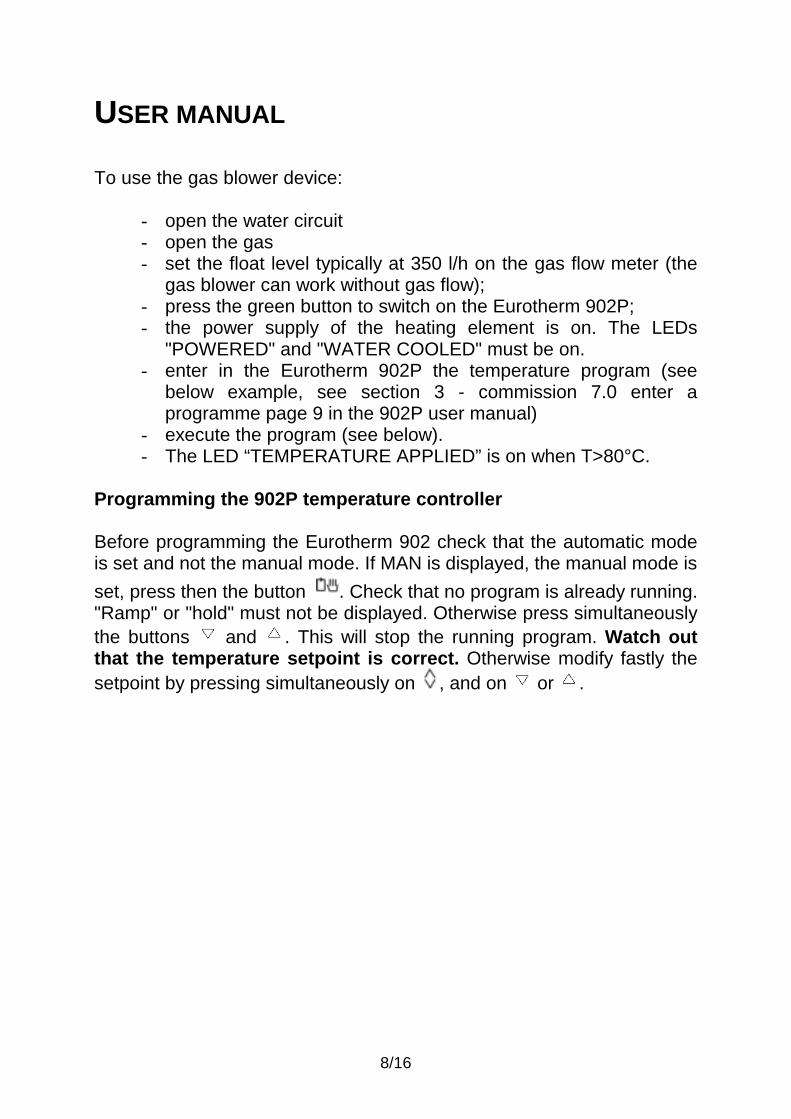
USER MANUAL To use the gas blower device:
- open the water circuit - open the gas - set the float level typically at 350 l/h on the gas flow meter (the
gas blower can work without gas flow); - press the green button to switch on the Eurotherm 902P; - the power supply of the heating element is on. The LEDs
"POWERED" and "WATER COOLED" must be on. - enter in the Eurotherm 902P the temperature program (see
below example, see section 3 - commission 7.0 enter a programme page 9 in the 902P user manual)
- execute the program (see below). - The LED “TEMPERATURE APPLIED” is on when T>80°C.
Programming the 902P temperature controller Before programming the Eurotherm 902 check that the automatic mode is set and not the manual mode. If MAN is displayed, the manual mode is set, press then the button . Check that no program is already running. "Ramp" or "hold" must not be displayed. Otherwise press simultaneously the buttons and . This will stop the running program. Watch out that the temperature setpoint is correct. Otherwise modify fastly the setpoint by pressing simultaneously on , and on or .

9/16
-
0
2040
60
80100
120
140
160180
200
0 100 200 300 400
Temps [minutes]
Tem
péra
ture
[°C
]
The program described herebellow corresponds to the temperature cycle shown on the above picture. Programming:
- press and hold till OpEr is displayed - press on , PrOG is displayed - press on , Pr1 is displayed - press on and to select 1 °C per minute as rate for the first
ramp. - press on , Pl1 is displayed - press on and to select 60 °C as final setpoint. - press on , Pd1 is displayed - press on and to select 0.5 hour as dwell time. - press on , Pr2 is displayed - press on and to select 1 °C per minute as rate for the
second ramp. - press on , Pl2 is displayed - press on and to select 180 °C as final setpoint. - press on , Pd2 is displayed - press on and to select 1 hour as dwell time. - press on , Pr3 is displayed - press on and to select 2 °C per minute as rate for the last
ramp. - press on , Pl3 is displayed - press on and to select 0 °C as final setpoint.
10/16
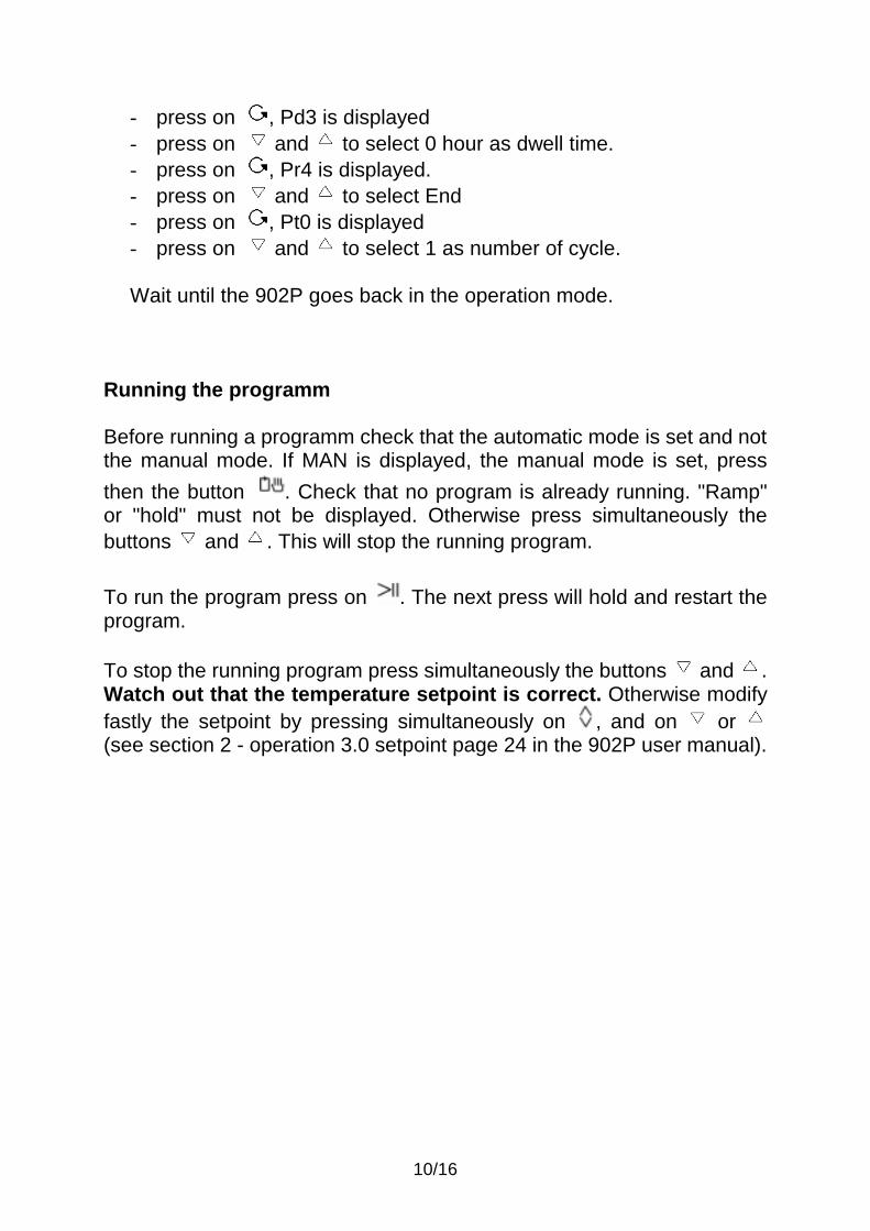
- press on , Pd3 is displayed - press on and to select 0 hour as dwell time. - press on , Pr4 is displayed. - press on and to select End - press on , Pt0 is displayed - press on and to select 1 as number of cycle. Wait until the 902P goes back in the operation mode.
Running the programm Before running a programm check that the automatic mode is set and not the manual mode. If MAN is displayed, the manual mode is set, press then the button . Check that no program is already running. "Ramp" or "hold" must not be displayed. Otherwise press simultaneously the buttons and . This will stop the running program. To run the program press on . The next press will hold and restart the program. To stop the running program press simultaneously the buttons and . Watch out that the temperature setpoint is correct. Otherwise modify fastly the setpoint by pressing simultaneously on , and on or (see section 2 - operation 3.0 setpoint page 24 in the 902P user manual).

11/16
902P heating program software Software installation with Windows™ 1) Insert the floppy disk HEATING PROGRAM in drive A: 2) Click on the Start button and select Run. 3) Type a:setup and click on the OK button. 4) The default directory is C:\Demo, you can not change it. Then click on the Ok button. 5) After a while you will get the following message : Setup has installed the software successfully and added the application(s) to the Program Manager. Click on the OK button. To run this program click twice on the Programmes/Cyberstar/”Heating program" icon. The Temperature program button can be pressed to define and/or run the heating temperature programs loaded in the 902P temperature controller driving the furnace heating element. The current program is plotted on the screen (see picture below). Every time a value is modified, the plot is updated. You can define up to 8 segments (ramp and dwell). A ramp rate of -0.2 means end of program (see Eurotherm documentation for further explanation). The Save button allows to update the defined programs on the hard disk (C:\TESTPT\DEMO\HEAT.TXT file). The Cancel button allows not to take into account any modification. The Run button allows to start immediately the defined program if necessary. All measurements are stored on the hard disk (C:\TESTPT\DEMO\DATA.TXT file). The Exit button ends the program.

12/16

13/16

14/16
REGULATION PARAMETERS The following parameters for the Eurotherm 902P are advised to obtain a temperature stability of +/-0.5 °C:
- Pb=5.7% - Ti=40 - Td=6.6 - Cbl=Non - Cbh=Non - C1h=23.3% - Maximum power Hl=100% - Maximum temperature setpoint Sph=1000°C
Watch out, as factory settings the ramps rate are defined in °C/minute. In order to avoid damaging the device it is advised not to use ramp rate higher than 10°C/minute. The factory settings are the following:
- C3 = 2400 - C6 = 0111 - C7 = 0000 - Al1 = 80°C - Add = 0

15/16
GAS FLOW METER The graduation of the gas flow meter is ln/h Air @ 20°C. The full scale is 600 is ln/h Air @ 20°C. The graph float travel as a function of the flow is given hereafter. To define the graduation corresponding to gas flow of other gas than air a conversion factor is used: Gas flow (ln/h) = graduation * (µair / µgas)1/2 Where µair is the air volumic mass, is the gas used volumic mass. µair = 1.293 g/l µnitrogen = 1.251 g/l µargon = 1.784 g/l Exemple: To set a gas flow of 340 ln/h Argon, the graduation must be set to: graduation = 340 / (µair / µargon) = 340 / (1.293/1.784)1/2 = 399.4
16/16
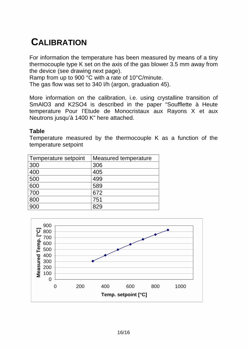
CALIBRATION For information the temperature has been measured by means of a tiny thermocouple type K set on the axis of the gas blower 3.5 mm away from the device (see drawing next page). Ramp from up to 900 °C with a rate of 10°C/minute. The gas flow was set to 340 l/h (argon, graduation 45). More information on the calibration, i.e. using crystalline transition of SmAlO3 and K2SO4 is described in the paper “Soufflette à Heute temperature Pour l’Etude de Monocristaux aux Rayons X et aux Neutrons jusqu’à 1400 K” here attached. Table Temperature measured by the thermocouple K as a function of the temperature setpoint
0100200300400500600700800900
0 200 400 600 800 1000Temp. setpoint [°C]
Mea
sure
d Te
mp.
[°C
]
Temperature setpoint Measured temperature 300 306 400 405 500 499 600 589 700 672 800 751 900 829