gas chromatograph gc-14b user’s manual - inicio liuc... · 22 1 -40323 gas chromatograph gc-14b...
TRANSCRIPT

22 1 -40323
GAS CHROMATOGRAPH
GC-14B
USER’S MANUAL
I READ AND UNDERSTAND THIS MANUAL I BEFORE OPERATION. SAVE THIS MANUAL. 1
SHIMADZU CORPORATION ANALYTICAL INSTRUMENTS DIVISION
KYOTO, JADAN

Copyright 0 Shimadzu Corporation 1993. All rights are reserved, including those to reproduse this publication or parts there of in any form without permission in writing from Shimadzu Corporation.
Information in this publication is subject to change without notice and does not represent a commitment on the part of the vendor.
Any errors or omissions which may have occurred in this publication despite the utmost care taken in its production will be corrected as soon as possible, but not necessarily im- mediately upon detection.
Note that Shimadzu does not have any obligation concerning the effects resulting from the application of the contents of this manual. Shimadzu Corporation will continue to supply original Shimadzu maintenance parts associat- ed with a given product for a period up to 10 years from the cessation of production of that product. Please be informed that after this period of time, Shimadzu Corporation cannot guar- antee supply of such original maintenance parts. However, following discontinuation of a product, the period of availability of maintenance parts which have been produced on a sub- contract basis is up to the discretion of the concerned Subcontracting company.
MS-DOS and MS-Windows are trademarks of the Microsoft Corporation.

Safety Precautions
This gas chromatograph is an analysis system designed to perform qualitative and quantitative
analysis .
For safe operation, observe the following precautions. If not observed, the safety may be
compromised.
1. Use the unit only for the purpose for which it is intended.
2.
3.
4.
Follow the procedures, warnings and precautions described in the manual.
Do not disassemble or modify the unit.
For repairs, contact our sales office or service representative.
THREE CATEGORIES OF DANGER SYMBOLS ARE USED THROUGHOUT THE MANUAL.
-1 Used for situations that may cause death or serious injury. -1 Used for situations that may cause slight injury or damage to
the instrument. Emphasizes additional information or provides tips for easier operation.
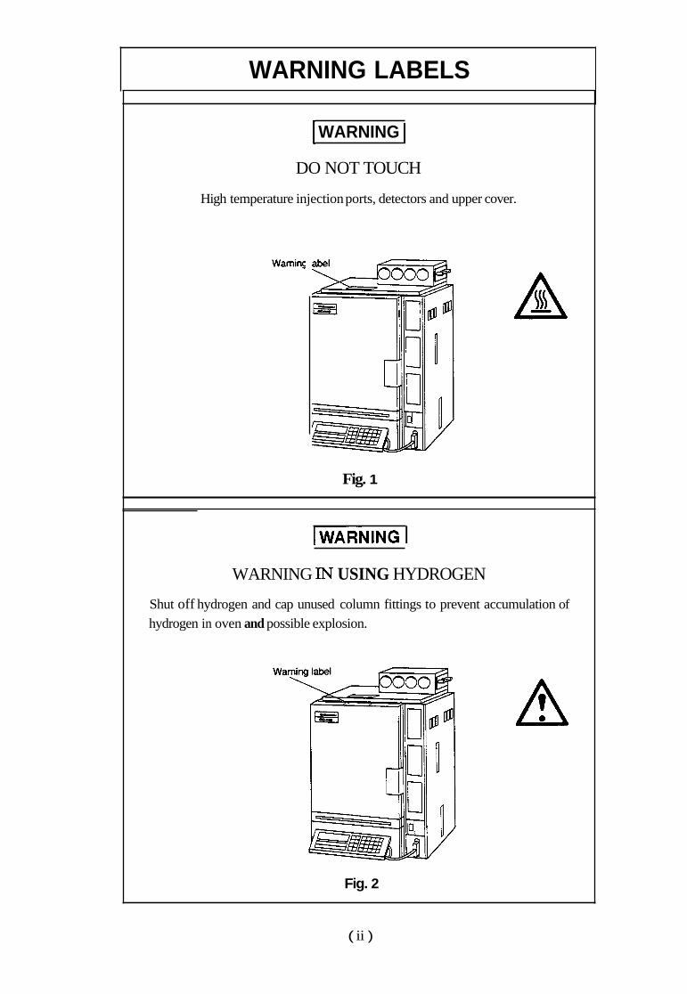
WARNING LABELS
WARNING I DO NOT TOUCH
High temperature injection ports, detectors and upper cover.
WaminC
Fig. 1
WRNING I WARNING IN USING HYDROGEN
Shut off hydrogen and cap unused column fittings to prevent accumulation of hydrogen in oven and possible explosion.
A
Fig. 2
( ii )

HOT AIR EXHAUST
Keep temperature sensitive materials away from opening.
Fig. 3
A
HIGH VOLTAGE
Disconnect power cable before removing cover. Refer servicing to qualified service personnel.
4 Warning label
A
Fig. 4
( iii )

WARNINGS IN USING HYDROGEN
When hydrogen gas is in use, care should be exercised in order to prevent accident. 1.
2.
3.
4.
5.
Connect gas lines correctly. Do not connect the hydrogen line to the air inlet, or hydrogen will leak excessively. When the device is not in use, the main valve of the hydrogen gas cylinder or generator must be closed. Also, make sure that there is no gas leakage from the main valve of the supply. The flow line for hydrogen gas should be checked for leakage whenever it is used. To prevent buildup of explosive concentration in case the hydrogen gas leaks, the room in which the device is used should be well ventilated. When analyses are completed, close the main valve of the hydrogen gas container immediately before performing other procedures.
Wami Wami
A
Fig. 5

EMERGENCY MEASURES
In an emergency such as trouble detected in the gas chromatograph, take the following countermeasures.
Before restarting operation, check the gas chromatograph. Contact our service personnel if necessary.
Emergency stop operation
1. 2. 3.
4.
! power cable.
Turn OFF the power switch for the gas chromatograph. Turn OFF all power switches of the supplied equipment. Close the main valve that supply the carrier gas, hydrogen, air, and make-up gas. Shut down the power supply.
0 When the power cable is fixed to the switchboard with the screws, turn OFF the switch on the board. When the power cable is connected with the plug, disconnect the 0
GC-14B
I
Power switch ' \
n
li Power cord
Fig. 6 Power switch and power cable for the gas chromatograph
( v >

Other Symbols
@ indicates protective conductor terminal. Grounding circuit continuity is vital for safe operation of equipment. Never operate equipment with ground conductor disconnected.
indicates functional earth terminal. I

Con tents
1 . Introduction 1.1 Installation Environment ..................................................................................... 1 . 1 1.2 Parts List ............................................................................................................ 1 . 3
2 . Specification ...................................................................................................... 1 . 6
2 . Installation 1.1 Inspection at Unpacking of GC Main Body ...................................................... 2 . 1
1.2 Installation ......................................................................................................... 2 . 2
2 . Setting of Column .............................................................................................. 2 . 7 3 . Addition or Change of Installation Place of Sample Injection Port Unit .......... 2 -16 4 . Types of Sample Evaporating Chamber Unit .................................................... 2 -18 5 . All input and output connection ........................................................................ 2 -21
3 . Operation 1
1 . 2 .
Explanation of Operation Panel ......................................................................... 3 . 1
Setting Procedures for Operation Check ........................................................... 3 . 2
4 . Operation 2 1 . Classification of Keys ........................................................................................ 4 . 1
2 . Explanation of Individual Keys ......................................................................... 4 . 7 3 . Control Parameters and Default Values ............................................................ 4 . 13
4 . Meanings of Indication Lamps .......................................................................... 4 -17 5 . Function of Files ................................................................................................ 4 -18
6 . Error Messages, etc ............................................................................................ 4 -19
5 . Operation 3 1 . Temperature Setting .......................................................................................... 5 . 1
2 . Detectors ............................................................................................................ 5 -28
3 . Starting and Ending Temperature Control ......................................................... 5 -31
4 . Operation Performed During Analysis .............................................................. 5 -36
5 . Time Program .................................................................................................... 5 -47 6 . Files ................................................................................................................... 5 -52
7 . Other Operations ................................................................................................ 5 -55 Appendix 1 Error Display ....................................................................................... 5 -60

6 . Construction and Maintenance 1 . Construction ....................................................................................................... 6 . 1
2 . Removal and Replacement of Column Oven Door.
Rear Panel and Side Panel ................................................................................. 6 . 3
Troubleshooting and Remedy ............................................................................ 6 . 7
Maintenance ....................................................................................................... 6 -10 3 . 4 .
7 . SPL-14 SpliUSplitless Smaple Injector 1 . Split/Splitless Sample Injection ......................................................................... 7 . 1
2 . Installation ......................................................................................................... 7 . 6
8 . Flow Controller 1 . Introduction ....................................................................................................... 8 . 1
2 . Components of Flow Controllers ...................................................................... 8 . 3 3 . Specifications ..................................................................................................... 8 . 13
4 . Construction and Part List ................................................................................. 8 . 14
9 . Capillary Column Assembly (Option) 1 . 2 . 3 .
Capillary Column Holder CLH- 14 (P/N 22 1-32995-9 1) .................................. 9 . 1 Components for Capillary Column Flowlines ................................................... 9 . 5
Capillary Column Flowline Parts ...................................................................... 9 . 9
10 . Outline of Optional Units 1 . Current Loop ...................................................................................................... 10- 1
2 . COS-GC14A ...................................................................................................... 10- 5
3 . Control of GC-14B by Personal Computer Outline .......................................... 10- 6
4 . Heated Connection Unit .................................................................................... 10- 10
5 . Add-on Unit Case .............................................................................................. 10-1 1
11 . Thermal Conductivity Detector (TCD) 1 . Heneral Description ........................................................................................... 1 1- 1
2 . Structure ............................................................................................................. 11- 2 3 . Mounting the TCD in the Main Body ............................................................... 11- 5
4 . Carrier Gas Flow Line ....................................................................................... 11- 8
5 . Operation ........................................................................................................... 1 1- 9 6 . TCD Troubleshooting ........................................................................................ 1 1 . 1 1

12 . Hydrogen Flame Ionization Detector (FID)
1 . General Description ........................................................................................... 12- 1
2 . Structure ............................................................................................................. 12- 3
3 . Mounting FID in Main Body ............................................................................. 12- 5
4 . Operation ........................................................................................................... 12- 7
5 . FID Troubleshooting ......................................................................................... 12- 1 1
221 -4001 0-01
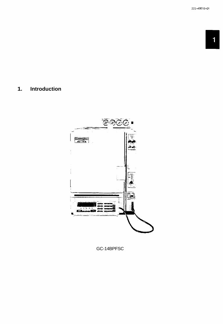
1. Introduction
GC-14BPFSC

. PI Thank you very much for your purchase of Shimadzu's GC-14B series Gas Chromatograph.
The GC-14B series Gas Chromatograph, which is controlled by microcomputer, is a multipurpose
gas chromatograph exhibiting high performance. This GC unit has particularly distinguishing features
-~
such as small installation area requirements and large system expansion capabilities.
1.1 Installation Environment
1.1.1 Operating Temperature, Specified Temperature, humidity
Although the unit operates in the range of ambient temperatures of 5°C - 40°C and relative
humidity of 5% - 90%, use it within the range of 10°C - 30°C ambient and 50 - 60% relative
humidity for longer service life and the optimum specifications. (Operating temperature range: 5°C
- 4OoC, specified temperature range: 10°C - 30°C)
Installation place
1-1 As high-temperature (400°C) air is exhausted from the rear of the unit, do not
place combustible things around the unit.
The following installation area is required. Install the unit at place which is protected from vibra-
tion and direct sunlight.
Dimensions of installation place
External dimensions of the unit
H : Height 520mm
W : Width 400mm
D : Depth 475mm
E : Height of flow controller 70mm
A : Required space behind the unit
300mm or more
B : With option unit 76mm
C : For C-R7A Chromatopac 364mm
Weight of GC-14B main body: Approx. 40kg
1 - 1

I Caution I The sample is vaporized and discharged from the split vent, purge vent, and detector vent, etc. When analyzing toxic substance, properly ventilate the place and provide a means of recovery if necessary.
1.1.2 Electro-magnetic wave and the noise of power source
This unit should not be used in the strong electro-magnetic field. And it should not be used with
the power source which conteins a strong noise. Such a noise will disturb the unit to give correct
data.
1.1.3 Power
115/22OV/23OV/24OV AC (50HA60Hz) and 2.2kVA max. capacity are necessary for the power
source of the unit (with no satellite oven installed.)
Column oven 1.3kVA
INJ block 150VA
DET block 300VA
TCD block 200VA
Total consumed power is calculated by totalling the power consumed by INJ, DET, column
oven, and AUX blocks.
Range of source voltage
Specified range of source voltage k 5%
lk 10%
Power cable
-1 High Voltage 1. When connecting the power cable directly to the terminal block on the
distribution panel, be sure to turn OFF the switch on the distribution panel before installation. Always supply the power from the power source that incorporates the leakage breaker. Do not put any heavy articles on the power cable.
2.
3.
In the case of 115V power, the maximum capacity of power exceeds 15A. So the power cannot
be supplied from a general outlet. Accordingly, supply power from a specially-wired terminal with
large capacity. Exercise caution in wiring in accordance with the functions and color of the power
cable, as described below.
1 - 2

Pole Color of power cord leads of GC main body
Black HOT I I
White I NEUTRAL I No electric potential OV against ground.
Remarks
Electric potential of 11 5/220V against ground.
Green I GROUND I Ground
In the case of 22OV/23OV/24OV power, the plug of the power cable can be connected to a
general outlet. The rated voltage is printed on the equipment.
1.2 Parts List
1. Main body of GC .......................................................... 1 (Note 1)
2. Flow controller .............................................................. 1 (Note 2)
3. Pack of accessories ........................................................ 1 (Note 3)
Note 1. At shipment, detectors TCD and FID are incorporated in the main body, and ECD,
and FPD are usually separately packaged.
Note 2. Quantity and type of detectors are different depending upon the ordered types
and combination.
Note 3. Refer to the attached sheet for the contents of the accessories package.
1 - 3
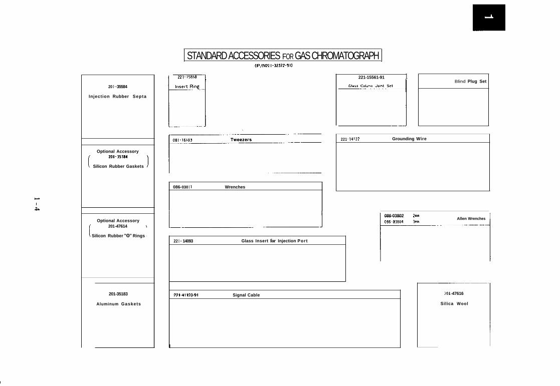
20 I - 35584
Injection Rubber Septa
Optional Accessory 201-35184
Silicon Rubber Gaskets I
Optional Accessory 201 -47614
Silicon Rubber "0" Rings
201-35183
Aluminum Gaskets
I STANDARD ACCESSORIES FOR GAS CHROMATOGRAPH 1 (P/N22 1-32372-91)
221-158581
Tweezers
086- 030 I 1 Wrenches
221-15561-91 1 Blind Plug Set
Grounding Wire 221 - 14 122
Glass Insert for Injection Port 22 I - 14093
I Allen Wrenches 086-03802 Zmn
221-41 123-91 Signal Cable
I
201 -47616
Silica Wool

Overall Configuration
f Injection Port System A variety of injection port artangements are available depending upon the analytical requirements.
Flow Controller Flow control configuration depends upon analytical requirements
Optional Controller Case Allows simultaneous installation of upto 4 detectors
Operator Interface Detachable keyboard and display unit for parameter setting, control and monitoring, etc., of the instrument.
L 1
1 - 5

2. Specifications
Column oven 0 Dimensions of column compartment: 230 (W) X 140 (D) X 360 (H) mm
Length of columns to be accommodated:
S t d e s s steel column 10m X 2
3m X 2 Glass column
Capdlary column lOOm X 1
Range of temperature setting: Temperature; -80-+399 I"C step
O-40°C/min 0 . 1 " ~ step
0.1"C step
Rate of temperature rise;
Constant temperature hold time; 0-655 min
Program stages 5 stages max.
Range of temperature control (with power voltage of 1OOV) Range of h e a r temperature 3O0C/min 150°C or less increase:
2o0C/min 250°C or less
1o0C/min 330°C or less
5"C/min 399°C or less
When INJ and DET temperature is 300"C,
room temperature + 15°C
When INJ and DET temperature is 150"C,
room temperature + 10°C
Additional cryogenic equipment is required for control-
ling at lower temperatures than those above.
Approx. 9 min to reduce from 399°C to 100°C with
room temperature of 25°C.
Approx. 14 min for reducing from 399°C to 50°C with
room temperature of 25OC
Lower-limit temperature:
Cooling speed:
Detector oven
Range of temperature setting:
TCDoven
Range of temperature setting:
Sample injection port unit
Range of temperature setting:
Room temperature - 399°C (in 1°C steps)
Room temperature - 399°C (in 1°C steps)
Room temperature - 399°C
1 - 6

U Sample injection port unit (Either one of the following units is provided)
Single injection port unit: For packed glass column, combination type of glass
insert and on-column injection, 1 flow line
Dual injection port unit:
Injection port unit for for capillary columns:
For packed glass column, combination of glass insert
and on-column injection,
Exclusive injection port for capillary analysis
2 flow lines
Overheat protection circuit 3 circuits
1. 450°C-fixed independent protection circuit.
2.
3.
Protection circuit for which the upper-limit temperature can be set via key operation.
Overheat protection circuit by CPU abnormality detection
I Combination of Detectors
1. Four detectors at maximum from among TCD, FID, ECD, FPD, and FTD can be simul-
taneously installed to the detector oven of the GC main body.
be set simultaneously.
Two TCD detectors cannot
2. Only two types of detector controllers (except FTD) can be installed simultaneously to
the control section of the GC. Another unit should be applied for installing three or more
detector controllers, or FTD.
1 - 7

22 1-4001 0-92
2. Installation
.- .- .-I

I
1. Installation
I Note I GC- 14B weighs more than 40kg.
knock it during unpacking.
1.1 Inspection a t Unpacking of GC Main Body
0 Main body of GC-14B Gas Chromatograph
So, it should be carried by two people, and care should be given not to drop it or
@ Main body .................................................... @ Keyboard unit ................................................ 1
Single model .............................................. 1
@ Flow controller
Dual model ................................................ 2
@ Package of standard accessories
0 Detectors
TCD ........... Incorporated in the GC-14B.
FID ........... Incorporated in GC-14B. For dual flow lines, they may be packed separately
for each flow line, and added on installation.
Other detectors ....... They are packaged in separate boxes, and added on installation.
Flow controller
The flow controller is included in the package of the main body. Mount it at the place
shown in the diagram below on installation.
2 -1

.
1.2 Installation
Operations
1) Place it on the table.
_E .
Flow controller (Another flow controller is placed above for dual flow lines.)
Remarks
@ Column oven door
@ Sub door
@ Operation panel (keyboard) of the main body
a Power switch
a Heater switch
a Keyboard unit cable connector
@ @ @
Detector control section (normally TCD)
Detector control section (normally FID)
Capillary split/splitless injection system con-
troller
2 - 2

2) Installation of keyboard unit
,*. 8 .
d
3) Open the oven door and check that
no foreign matter exists inside.
I
Insert the keyboard unit cable connector into the
recess in the column oven as shown below. Observe
screws firmly. u the key on the connector. Tighten the two knurled
0
!b 3 For fixing the keyboard unit to the sub door,
mount the metal brackets provided by the screws
indicated by the arrows.
Temperature control sensor
3 Overheat prevention thermocouple
@ Door switch (Heater is turned OFF if the door
is opened.)
9 Sub door mounting hole
Detaching 7 l Q
2 - 3

4) Inspect the rear of the oven
5) Connection of power in the case of
11 5V power.
6) Insert of signal cable
A
9 Fan motor clamping screws
Remove the fan motor clamping screws located
at @ before operation. As these screws are only
used for fixing the motor during transportation,
they should be removed prior to operation to pre-
vent vibration.
removal.
3 Exhaust port during cooling
As hot air is exhausted from this port, do not
place any dangerous materials near the back of the
oven. (30cm or more clearance is required to pre-
vent danger.)
3 Intake port during cooling
3 Power cord (Specifications are different depending
upon source voltage.) Check that the power switch on
the front panel is OFF before connection.
Connect as follows in the case of 115V power.
black ....... connected to HOT side of AC line
white ...... connected to NEUTRAL side of AC lint
green ...... grounded
to a power source with capacity of 115V AC. In
the case of 22OV/23OV/24OV power, connect the
plug of the power cord to the power source.
@ signal cable connect port
Insert signal cable to connection port at the
rear of the control section of the detector to be
used. For detaching the signal cable, first remove
lock a by screwdriver or the supplied tool,
then pull the connector out.
U 2 - 4

7) Lead wire feed through
Cut the plastic joints to open the feed through when necessary.
8) Inspect the top
I 9
9) Set FID guard
Feed through for current loop and/or RS-232-C
interface cords
3 Feed through for external control signals
AUX terminal board
3 ~ o p c o v e r
3 INJ/DET cover
3 INJunit
When an INJ unit is already installed in the
main body, inspect it in that condition (or after
inserting a glass insert). For changing the position
or type of INJ unit, refer to paragraph 3.
3 ov oven When the GC unit is not provided with a TCD,
this surface is continuous with @ .
8 Left-side face, TCD vent
3 Set FIDguard
FID guards are incorporated in the main body
at the plant before shipment.
If adding an FID later, set the guard as in the
method shown in the diagram on the left.
2 - 5

10) Connect flow controller @ Flow controller
@) Positioning pin
@ Piping
Connect the pipes exiting from the notch in the
back of top cover to the OUT-side joints on the
back panel of the flow controller. The pipes are
color-coded and labeled for identification. Be sure
to connect each pipe to the correct joint.
Identification of pipes Yellow
Carriergas FLOW2
. FID Hz FLOW 1
I- / Red
\ - I
FLOW2
. FID AIR FLOW 1 # A # 1
/ Blue
FLOW2 # A H 2
Yellow
TCD Reference side #T#2
Installation of column .......... Refer to paragraph 2 of the ‘‘Installation of Column” section.
Details of gas supply and flow controller ........ Refer to the instruction manual for the flow
controller.
Addition of INJ unit .......... Refer to the paragraph with reference to addition, and change of
position of INJ unit.
Addition of detector .......... Refer to the instruction manual attached to each detector.
-1 Do not turn on the power if a TCD is installed without first establishing carrier gas
flow. TCD filaments may be damaged otherwise.
2 - 6

2. Setting of Column
2.1 Glass Column (On-column type)
Injection port side Detector side
0 0
c
r I
Cap nut \ Washer \ Glass column joint
i
@ I
Glass column
1 spring P/N 221-15561-91
- End of packing must be below the column connection joint.
01
1) Fix parts @ - @ on t h e d e t andoutlet
\ Backring /
sides of the glass column as shown in the diagram
on the left. Be careful about the orientation of
back rings @ . (The ends with the smaller outer
diameter should contact the graphite ferrules.)
2) Lightly tighten nuts @ by hand, and press the
column up until the end of the column bottoms in
the column joint on the detector side.
3) With the column correctly positioned, tighten
the joint at the injection port side with wrenches.
I Caution J As excessive tightening may
damage the column, tighten the
joint gradually while checking
leakage with soapy water
applied to the joint until the
optimum extent of tightening is
found.
If this procedure is conducted while watching the
carrier gas pressure gauge, when carrier gas is
controlled by mass flow controller, the pressure gauge
indication rises when the leakage stops.
4) Tighten the column joint on the detector side
to a similar extent.
I-- PartsNo. 1 Name of parts
@ 1 221-15563-91 1 Graphite femle (4)
2 - 7

2.2 Glass Column (Insert type)
Graphite f e d e for TCD use
Sleeve
Inlet and outlet necks of the column are of differ-
ent lengths. Insert the glass insert into the shorter
neck, and set the assembly into the injection port.
1 Tightening method is the same as that for the on-
column type described in the previous paragraph.
* Two types of glass inserts are available to fit
the inner diameter of the glass column to be used.
A glass insert of 3.2@ is provided in the set of
Set of 10 P/N 221-10076-91
PIN 221-10073
standard accessories.
Glass insert, 3.26 I P/N 221-14093 I For columns of inner diameter 3 - 3.46
Glass insert, 2.66 I P/N 221-14094 1 For columns of inner diameter 2.5 - 2.76
2.3 When Connecting Glass Column to TCD The TCD has no passage to purge the column out-
let as in other detectors. With the FID, for instance,
hydrogen gas enters at the column outlet to purge
dead space.
Accordingly, for TCD, the graphite ferrule and
back ring are special ones, and the seal occurs at the
bottom of the column connection port to minimize
dead space.
Graphite f e d e for TCD use
Sleeve
r
i Glass column joint
2 - 8
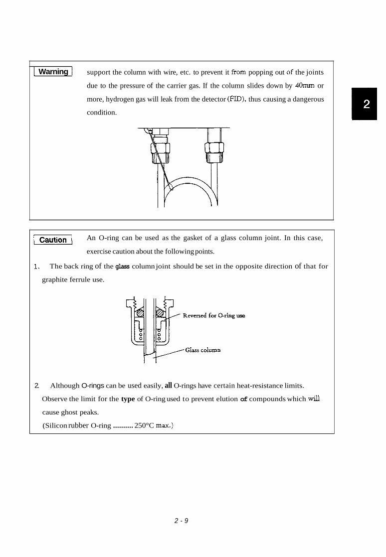
I Warning I support the column with wire, etc. to prevent it from popping out of the joints
due to the pressure of the carrier gas. If the column slides down by 40mm or
more, hydrogen gas will leak from the detector (FID), thus causing a dangerous
condition.
-1 An O-ring can be used as the gasket of a glass column joint. In this case,
exercise caution about the following points.
1. The back ring of the glass column joint should be set in the opposite direction of that for
graphite ferrule use.
2.
use
Although O-rings can be used easily, all O-rings have certain heat-resistance limits.
Observe the limit for the type of O-ring used to prevent elution of compounds which d cause ghost peaks.
(Silicon rubber O-ring .......... 250°C max.)
2 - 9

2.4 Stainless Column
As no parts for connecting a s t d e s s column are provided with the standard unit, purchase
stainless steel column adapters separately.
Stainless steel column adapters can be used interchangeably for Shimadzu GC-7A, GC-9A,
1) Stainless steel column adapters
for Shimadzu gas chromatographs
(for SUS column)
c 1
7 SUS column
) Stainless steel column adapter
P/N 221-14087-91 for INJ
) Stainless steel column adapter
P/N 221-08882-91 for DET
) Stainless steel column adapter
P/N 221-10079-91 for TCD
-1 When inserting a glass insert
into a SUS column adapter, set
an insert ring @ (P/N 221-
15858) as shown in the
diagram. This prevents
breakage of the glass which
may otherwise occur due to the
difference in heat expansion
between the glass and metal.
For connecting a SUS column, tighten with column gasket @ . (When aluminum gaskets are applied,
overlap a few gaskets together.)
Column gasket (Aluminum)
Set of 100 P/N 201-35183
Column gasket (Silicon rubber)
Set of 50 P/N 201-35184
Some SUS column adapters on the INJ side use
stainless steel pipes instead of glass inserts. In this
case, join by glass column joint.
0
SUS column adapter (On-column)
P/N 221-17920-91
2 - 10

2) Adapters for use when fractional-inch-
sized stainless steel pipe is used for the
column
These adapters are for Shimadzu stain-
less steel column in 1) with swagelock type
joints.
Column outer diameter
For l/S-inch column
For 3/16-inch column
A I B
P/N
221-22910-22
22 1-229 10-23
I For 1/4-inch column
C
221-22910-24
-1 Fractional-inch-sized columns
For 3/16-inch column
For 1/4-inch column
or materials for such columns
221-22910-73
221-22910-74
are not supplied by Shimadzu
except for the adapters.
For 1/4-inch column
A. SUS column adapter on INJ side
(On-column type)
221-229 10-64
B. SUS column adapter on INJ side
(Glass insert type)
C. SUS column adapter on DET side ~~~
Column outer diameter I P/N
For l/S-inch column I 221-22910-72
D. SUS column adapter on TCD side
Column outer diameter I p/N
For l/S-inch column I 221-22910-62
For 3/16-inch column I 221-22910-63
2 -11

2.5 Setting of Capillary Column
For capillary column analysis, use the split/splitless system (SPL-14). The GC-14B capdary
model (GC-14B SC model) is provided with the SPL-14 as standard. For the standard GC-14B
packed column model the SPL-14 is an optional accessory.
Refer to chapter 7 for details of the capdary system.
1. When setting a capiUary column to the SPL-14
L8' I t
Setting of graphite ferrules for the capillary column
Slide a graphite ferrule @ onto both ends of the
capdary column, and tighten by nuts @ . The nuts
can be tightened sufficiently by hand.
/[Caution/ Excessive tightening by wrenches will cause breakage
of the neck of the joint.
Expanded diagram of capillary column joint
Graphite ferrule P/N 221-32126-05
Split nut P/N221-32705
Length between graphite ferrule and column end
Injection port side A 35mm
Detector side B 75mm
When the detector is an FID, and the column is
to be inserted upto the middle of the nozzle, the
2 - 12
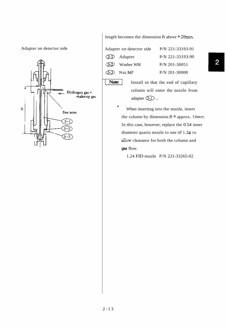
Adapter on detector side
1
A C
-.
B
V I
1
length becomes the dimension B above + 20mm.
Adapter on detector side P/N 221-33193-91
a Adapter P/N 221-33 193-90
a Washer WM P/N 201-30051
a NutMF P/N 201-30008
1 Note I Install so that the end of capillary
column will enter the nozzle from
adapter @ .
* When inserting into the nozzle, insert
the column by dimension B + approx. 10mm.
In this case, however, replace the 0.54 inner
diameter quartz nozzle to one of 1.24 to
d o w clearance for both the column and
gas flow.
1.24 FID nozzle P/N 221-33265-02
2 - 1 3

kT. - z
aPp?aN
1 I I
I I I I I I I I I I I
16-08PZS-TZZ N / d iaadEpv
TO-866ZS-TZZ N / d u a q s-13
n I

2.7 When setting a wide-bore capillary column to an injection port meant for packed column use.
Some capdary columns have an inner diameter of 0.53mm (wide-bore column). Such columns
Nut MF
Set of 10 graphite fermles
Nuts
Set of 4 graphite ferrules
Glass column joint
do not aim at high resolution separations like those columns with small diameters (O.Imm.-0.3mm).
The value of such columns is the importance placed on the merits of the inactive stationary phase
carrier, usually silica. Wide-bore columns can be set to the split/splitless system described in 1).
1
1
2
1
1
However, as a n easier (and less costly) method, a wide-bore column can be set to an injection port
intended for packed column use as the column can be loaded with the whole sample quantity.
The following adapters are used for this method.
Wide-bore column adapter (WBC attachment)
I N J side DET side
Wide-bore capillary column
PIN 221-29992-91
pm
221-29676
221-29757
22 1-38 1 07
201-30051
201-30008
221-32126-08
221-32705
221-15563-91
221-15561-9 1
Name of parts I Q'ty
WBC adapter, INJ
WBC adapter, DET
Glass insert
Washer WM I
2 - 1 5

3. Addition or Change of Installation Place of Sample Injection Port Unit
~
DI - D4
T1, T2
T3
H
11 "14
Sample injection port and various detectors of the GC-14B are installed at the places shown below.
Locations for detectors except TCD
Locations for column-teTCD connection
Spare
Piping port to column oven
Locations for injection port unit
Detector Location is fixed, however, the injection port is unitized for relocation as required.
Detector oven
Sample injection port unit
The diagram above is the top view of the detector section.
Setting holes I Uses
3.1 Location of Injection Port Unit
o When a glass column is used.
As shown here, the distance between glass column inlet and outlet should be 40mm o n
centers. For installing the column, fix the injection port unit
just in front of the detector to be used. As the TCD detector
uses T, and T, (see Section 11), TI can be used with injection u port unit attached at I,- or I , , and T, can be used with the
injector located at either I, or 13.
0 When a stainless steel column or capillary column is used.
As the distance between centers of the column inlet and outlet is flexible to some extent,
there is no restriction as to injection port location as with a glass column.
2 - 1 6

3.2 Installation of Injection Port Unit
Front Rear
Insert positioning pin through the hole in the injection port unit.
Injection unit
of the oven. This prevents the unit from rotating when
I
Insert a glass column from below to check the set position.
I nstdation procedures
1) Remove the insulating material at the
place where the injection port unit is to
be installed.
(Any of I, - I4 in the diagram shown
before, as required.)
2) When setting the hexagonal part of the
injection port unit into the hexagonal hole
of the column oven, pass the locating pin
through the positioning hole on the top
flange of the unit.
3) When both items above are done, press
the unit downward to assume the position
shown in the diagram.
4) Fill any empty space around the unit
with insulating material (ceramic wool).
(Thickness of the insulating material
should be approximately 20 - 40mm.)
[Note] For those unused holes provided
with no insulating material, apply
aluminum foil to cover the holes
before fding with insulating material.
5) When using a glass column, after instal-
ling the unit, check that the glass column
can be inserted from below smoothly
(and falls freely when released). If the
column binds, small adjustments should
be made otherwise the column may
fracture when the joints are tightened.
6) Replace the flange to hold the unit in
place.
2 - 17

4. Types of Sample Evaporating Chamber Unit
This GC unit has the sample injection unit, which is installed to the top of column oven. With a l l
sample injection port units removed, the space leading to the column oven as shown in the diagram
can be obtained.
4.1
ing to the
Injection Port Unit Remarks (P/N)
Dual injection port unit
Dual injection port for packed column use
2 - 1 8
For source voltage 115V (PIN 22
220V (P/N22
230V (PIN22
-29280-92)
-29280-93)
-29280-3 8)

4.2
Single injection port unit
Single injection port for packed column use
For source voltage 115V (P/N 221-31222-92)
220V (P/N 22 1-3 1222-93)
230V (P/N 22 1-3 1222-38)
SP/SPL Iniection port
Single split/splitless injection port for capillary
column use
For source voltage 11 5V (P/N 22 1-32547-92)
220V (P/N 221-32547-93)
230V (P/N 221-32547-38)
Wiring of Injection Port Units
Pin configuration for wiring of all injection port units is shown below.
Terminal unit
f - I iinit
Connector
I ' Heater cable ASSY I 1 - I PIN 221-32964-91 (115V. 220V, 240V) LkET3 - --A in the case of 230V
PIN 221-32964-38 (230V)
2 - 19

When installing or removing injection port units be certain the power switch is OFF before
plugging/unplugging connectors. If done with the power switch ON, the CPU sees a disconnection
of the circuit, thus actuating the protective circuit and automatically turning all heaters OFF at
that point.
vl When the AUX-2 temperature control function is not being used for any sections,
injection port temperature can be controlled by this circuit. In this case, the following
parts are necessary:
Connect to terminals No. 3 and 4. 1 (AUX)
Connect the thermocouple to the AUX thermocouple terminal by properly connecting + and - . (*)
%) Insertinto JXETj. Heater cable ASSY P/N 221-32964-93 (1 15V, 220V, 24OV)
Insert into the AUX pin on the PC board. Short pin
P1 N 070-53 2 16-02 PIN 22 1-32964-30 (230V)
The most important thing for this operation is to correctly connect heater, heat sensor, and
thermocouple to the PC board in accordance with the way shown. If they are not properly con-
nected, temperature control does not function correctly causing excessive increase or decrease
of temperature.
Note I * As a standard, safety circuits with thermocouples are provided at 4 places in the GC-
14B temperature control section. If the safety circuits are already used for all 4 places,
the thermocouple of an additional unit cannot be connected.
In this case, apply either one of the following three methods.
1) Leave it without connection. In this case, this circuit monitors overheating
with the heat sensor for temperature control.
If any one of the safety circuits is not to be operated simultaneously with
other circuits, remove the thermocouple of that circuit, and exchange it with
the thermocouple of the added unit.
Add an external overheat protection device (option). In this case,
temperature control functions for an additional four more zones.
2 )
3)
2 - 20

5. All input and output connection
The connectors which are detachable for user are the outpuit connectors of detectors shown as the fol-
lowing figure.
The signal cable is connected to one of these connectors.
DETECTOR
CONNECTORS
n ‘“I I C 1 Power cord
I Note I Don’t touch the connector pins, or electrostatic discharge may damage the circuit.
2-21

22 1-400 10-03
3. Operation 1
This chapter describes operations necessary for power supply and checlung the operating
conditions of the instrument.

1. Explanation of Operation Panel
‘@g@@> Flow controller .-
S plit/splitless control section
Detector controller (shown: FID)
Heater switch
Temperature control display lamps
Power switch
Keyboard unit
3- 1

1 el For detectors such as the FID, FPD, and FTD, do not allow hydrogen to flow
with no column connected. Otherwise, hydrogen will escape into the column
oven creating an explosion hazard.
-1 Touching connectors or terminals with power on may damage instruments.
-1 Exercise caution in the following points when applying power with no column I
connected. 1. When a thermal conductivity detector (TCD) is provided, turn the
pushbutton switch of the TCD control section OFF, or set TCD CURRENT to 2mA or less to prevent damage to the TCD filaments. Check the inside of column oven. Particularly, check that no plastic objects (cushioning materials, etc.) are inside.
2.
2. Setting Procedures for Operation Check
(200°C) ---- Temperature of detector I Temperature
Temperature (180°C) - of injection unit
Find temperature ( 150°C 1 - - -
Rate of column oven ( loot/ temperature rise
Initial temperature ( 80°C 1
Room temperature
> Time
Power t switch ON START i Heater switch ON I READY 1
Detector FID RANGE 2 Polariy ( POL 1 1 (+I
Detector TCD CURRENT 2mA Polarity ( POL 1 1 (+I or less
Fig. 32 Example of Condition Setting for Operation Check
Procedures for setting conditions above are described below.
3 - 2

Setting
1) Turn the power switch ON.
m] Be sure to remove the clamp screws of the fan motor used for transportation.
2) Set detector temperature.
3) Set injection port temperature.
4) Set the column oven initial temperature
5) Set the initial temperature hold time
6) Set temperature rise rate
7) Set &al temperature
8) Set final temperature hold time
in the diagrams above can be omit-. ted when setting of column oven conditions is uninterrupted by other key operations.
Operation
o Fan motor rotates. LED of POLARITY 1 or 2 of detector lights.
Either LED of RANGE lights ON. Zero-point on-base LED may light. ~-
0 I*/ isdisplayed.
o Display after pressing the [ENTI key. I
1-1
3 -3

9) Set conditions of FID controller
10) Set TCD controuer
11) Monitor operation
in order to monitor the DET temperature
or COL temperature, depress
respectively before exercising keying-in
procedures for setting. -1 is not
necessary for monitoring* (except special
cases).
12) (START/
- COL m 1-1
- I I
13) Depress the heater switch.
1-1 RANGE2 lamp of the FID con- troller lights.
wl is displayed if the FID is not installed, or the controller switch is OFF.
-1 lights.
INJl(+) lamp of the controller
FI controller lights.
INJl (+) lamp of the TCD
JDETT. X X ]
Even if power is turned ON, the GC is in stand-by with no heaters working
I until the initial key is
depressed.
Room temperature is displayed.
I c 1 ~ P . k The temperature displayed may be somewhat higher than actual room temperature due to operation of the fan motor.
If the heater is turned ON the temperature displayed on the monitor above increases. (The LED inside of the heater switch lights.)
3 - 4

Upon completion of these procedures, the temperature of each section starts rising towards the
set value, and the READY lamp lights when the temperatures reach the set values. Program control
starts by pushing 1-1 while the READY lamp is ON. After the FINAL TIME (2 min), the
temperature is automatically reduced to return to the i n i t d condition, and waits for the next key
input for restarting. If the unit enters the cooling process (COOL) during the series of operations,
hot air exhausts from the vent at the rear.
Display upon supplying power
CITP XX :
ERROR CM :
INITIAL
FAULT
This is the normal monitor display of column oven temperature. But the actual
measurement value is not displayed as the -1 key has not yet been
pressed after power is supplied. The actual measurement is displayed by depress-
ing the 1-1 key.
This is displayed when the contents of memory become unreliable due to changes
while power is OFF, or changes of setting conditions just before turning power
OFF. If this is displayed, turn power OFF, and ON again after approximately
10 seconds.
When the contents of memory are greatly changed, the setting conditions in
all files are initialized, and this display is shown. In this case, repeat of the con-
ditions is necessary.
This is displayed if the system program has a fault. As the unit is unable to
function properly in this condition, contact our serviceman.
3 - 5

221 -4001 0-04
4. Operation 2
In this chapter, the various kinds of keys used for setting are described along with their functions.
For examples of operations which use these keys, please refer to chapter 5, Operation 3.

1. Classification of keys
1.1 Numeric keys
By pressing the numeric keys, the numerals selected are displayed. Actual input of the number
then on display occurs with the subsequent pressing of the ml key.
The range of figures that can be entered for display is up to 4 digits to the left of the decimal
point and up to two digits to the right of the decimal point. If the integer portion of a figure
entered exceeds four digits, the excess integer(s) becomes invalid. In the same way, if the decimal
portion of a figure entered should exceed two digits to the right of the decimal point, the excess
digit (s) becomes invalid.
1-1 1. No zero-suppression is effected in entering numerals. (If numeral 0 is entered at
the head of desired input for 1234, then actual input to the system is done as
0123, with the numeral 4 at the least significant digit being neglected.)
Be careful of the fact that pressing two or more keys at a time will result in an
erroneous key input.
2.
4-1

1.2 Command keys
The following 11 COMMAND keys are available for the outright execution of the selected
command by pressing the relevant key. (There is no need for subsequent pressing of any of the
numeral keys, following the pressing of such a COMMAND key.)
[-Emq /STOP1 lENT] F] -1 [HoLD] /FLM1 [sCANI rsmmq ISTWJ
1.3 FUNCTION keys
Functions of the following keys become effective only when any of these keys has been
operated, followed with input of an appropriate number (as described in para. 1.1) and by pressing
t h e m [ key.
1 INIT TEMPI [ PROG RATE1 1 FINAL TIME] [ FLVAL TEMPI
If, after pressing any of these keys, the [m] key is pressed without pressing a numeric key, the
value then set for the system is indicated on the display
1.4 Keys available specifically for monitoring
The key is used when the actual measured values of the chromatograph are to be
indicated on the display. The following keys cause display of measured values, as described below,
when pressed just after the Im] key:
INIT TEMP
INIT TIME
Actual temperature of column oven
Retention time counted from the moment when the START key was
pressed
Actual temperature in the column oven
Retention time counted from the moment when the START key was
pressed
Actual temperature in the column oven
PROG RATE
FINAL TIME
FINAL TEMP
4 - 2

COL
AUXl Actual temperature in AUXl
INJ
TCD-T
AUX2
DET-T
S -NO
PROG
STR-T
STP-T
SLP-T
RET-T
Actual temperature in the column oven
Actual temperature in INJ (sample injection port)
Actud temperature in TCD (TCD oven)
Actual temperature in AUX2 (auxhary temperature control unit)
Actual temperature in DET (detector unit)
Sample number in AOC at that time
Step number to be executed next (time program)
Time elapsed since Shift-down START
Time elapsed since Shiftdown STOP
Time elapsed since Shift-down STOP
Retention time counted from the moment when the START key
was pressed
Retention time counted from the moment when the START key
was pressed
HOLD-T
For each of the above keys, the relevant measurement value can be indicated on the DISPLAY as
soon as the key is pressed following the key.
Indicates the type of detector being used.
Indicates measurement value for flow rate.
(Obtainable, however, only when the optional flow measurement device
is connected.)
DET
FLOW
For the two keys shown above, the relevant data is indicated on the display by operating keys
as for example JWI lENTJ ; that is, by pressing the M G J key first, followed with
the pressing of either the m] or m\ key, as desired, and of the desired numeral key, and the
pressing of the (m/ key to complete the necessary key operation.
I .5 Interactive function keys
A. Once is pressed, the display and all the other keys are occupied for preparing the
time program for the period till the pressing of the [ESCP] key. r - I
By pressing the m, keys, the DIALOG lamp hghts and the display
indicates TIME?, signalling that the time program editing routine is in effect. To escape this
dialog routine for returning to the normal state, it is necessary to press the I 3
keys.
4 -3

B. By pressing the jFUNC/ key, the whole period till the pressing of the i-1 key is
dedicated to the necessary AUX function setting routine, with the content of the selected
function being displayed.
If there is no need for changing the content (value) then on display, you can either call up
the next function by the pressing of the F I key, or you can escape from the AUX func-
tion routine by pressing the [TI key. If the content then on display is to be changed,
first enter the correct number and then press t h e [ m I k e y . The display is then changed to
1
2
3
4
the next function in the list along with its value (if any).
By pressing the (desired number) [ENTI keys in that order, the FUNC DIALOG lamp lights and the content of the selected function is indicated on the display.
Selection of parameters required for AOC
Request for listing of time program to Chromatopac
Request for listing of AOC parameters to Chromatopac
Request for listing of GC parameters to Chromatopac
*3
*1
*1
*1
1.6 Setting functions not assigned to specific keys
Each of the following functions can be set by operaring the FUNC key. The functions avail-
able for setting and the corresponding code numbers are listed below.
5
6
Code- 1
Setting upper limit temperature of detector and injection units
Setting upper limit temperature in AUXl oven *4
Function
7
8
Setting upper limit temperature in column oven
Setting for link device (communications interface) *1
13
14
Starting self-diagnosis function (When this functionis executed, all the user settings are deleted and return to their default values.)
Setting the value “K”, the constant used for flow rate measurement *2 ~~~ ~~ ~~~
T e R e q u e s t for listing of temperature program to Chromatopac $1 ~~
*1.
* 2 .
Has meaning only if a Chromatopac is connected.
Has meaning onIy if a flow rate measuring device is connected. On some occassion,
however, this key may not be used depending on the type of particular flow rate
measuring methods employed.
Has meaning only if an automatic sample injector is connected. On some occassion,
however, this key may not be used depending on the particular type of AOC used.
*3.
4 -4

Explained below is an example of setting. --- -
In this case, 350°C is set as the upper limit for the detector temperature.
I Note I Once a desired function has been set by operating the FUNC key, all of the
subsequent key operations are effected in the dialog system, with the DIALOG lamp
being lit. It is necessary to press the ESCP key to escape from the dialog state effected
with the FUNC kev.
When input has been made for 350°C, the upper limit value for the temperature in AUXl oven,
that has just been set, appears on the display. Then press t h e m ]
in that order to terminate the FUNC dialog.
Upper limit temperature of of column oven of AUXl
Upper limit temperature Setting for link device I I I
I t should be noted, however, that the function for requesting listing of parameters to the
Chromatopac and the function of self-diagnosis are not included in this circular list and cannot be
selected no matter how many times the IENT] key is pressed.
If the function for setting parameters for the AOC is selected, each of the parameters involved
is displayed in succession each time the ]m] key is pressed.
AOC parameters available are the following 10 items. For details on them, please refer to the
instruction manual for the AOC in use.
4 - 5

STRK
ISNO
FSNO
REPT
WASH
WSHT
TWTE PROD
I J1T
IJ2T
Syringe stroke
Initial sample number
Final sample number
Number of times of repetitious sampling
Selection of washing liquid
Number of washing times
Setting for waiting time
Analysis time
Number of times of injecting sample to the injection port No. 1
Number of times of injecting sample to the injection port No. 2
4 - 6

2. Explanation of Individual Keys
1: TEh4P
I g I_ FINAL
I
I
Meaning
(1) When pressed first after supplying power to the GC proper, it means starting of power supply to each of the temperature control zones. (Up till this moment, no power has been supplied to these temperature control zones.)
(2) When pressed a second time and on after power is supplied to the GC, it means starting of the temperature program, time
time program and automatic sample injector ( A X ) .
Executes stopping the operations started as per item (2) above. Relevant operation is executed from the beginning when the
key is pressed next time.
Sets initial temperature for column ovem or AUXl. If no program is involved, temperature is controlled at this setting. (isothermal analysis).
Sets intitial temperature hold time for column oven or AUXI. If the heating rate is set at O"C/min, then the times set here becomes invalid.
Sets heating rate ('C/min) for column oven or AUXl (Can be set h-t up to 5 stages.)
Sets the temperature to be reached at the end of each rise stage of heating of the colum oven or AUXl.
4 - 7
Example
Column oven temperature is set at IOO'C
Temperature for AUXl is set at 100°C.
Initial time for column oven is set at 10 minutes. Wj-T-mm Initial time for AUXl is set at 10 minutes.
The 1st step heating rate is set at 5.2'C/min. Subsequent inputs with appropriate values allow setting for the 2nd and 3rd steps (and so on as required) for heating rate.
210" is set as the ultimate temperature to be attained in the 1 st step of the heating of the AUXl . Subsequent inputs with appropriate values allows setting for the respective temper- atures to be attained in the 2nd and 3rd steps of the program.


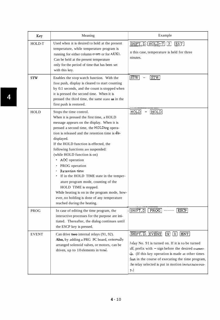
HOLD-T
STW
HOLD
PROG
EVENT
Meaning
Used when it is desired to hold at the present temperature, while temperature program is running for either column overn or for AUX1. Can be held at the present temperature only for the period of time that has been set with this key.
Enables the stop watch function. With the first push, display is cleared to start counting by 0.1 seconds, and the count is stopped when it is pressed the second time. When it is pressed the third time, the same state as in the first push is restored.
Stops the time control. When it is pressed the first time, a HOLD message appears on the display. When it is pressed a second time, the HOLDing opera- tion is released and the retention time is dis- displayed. If the HOLD function is effected, the following functions are suspended: (while HOLD function is on)
* AOC operation
* PROG operation - Retentiontime - If in the HOLD TIME state in the temper-
ature program mode, counting of the HOLD TIME is stopped.
While heating is on in the program mode, how- ever, no holding is done of any temperature reached during the heating.
In case of editing the time program, the interactive processes for the purpose are ini- tiated. Thereafter, the dialog continues until the ESCP key is pressed.
Can drive two internal relays (91, 92). Also, by adding a PRG PC board, externany arranged solenoid valves, or motors, can be driven, up to 10 elements in totaL
Example
n this case, temperature is held for three ninutes.
1- lEVENTl pJ [il /ENTI
Xelay No. 91 is turned on. If it is to be turned ,ff, prefix with - sign before the desired numer- rls. (If this key operation is made at other times :han in the course of executing the time program, :he relay selected is put in motion instantaneous-
Ye)
4 - 10

Meaning
i) Where an AOC is attached, the present sample number is indicated on the display. Direct designation of the next sample
Deletion of contents of the selected file. Deletes one step in the time program then in execution.
ii)
i) ii)
Example
[m -1 m]
[SHIFT.DI All the contents of File No. 3 are deleted.
Allows setting only when PROG program is in
I
Used for copying the contents of the present 1 -1 (copy] 141
1-1 m] execution. When a time program is executed, steps in the time program are repeated auto- matically with the selected File No. up to the particular step where this RETURN func- tion is programmed beforehand. After having executed repetitively by the preset number of times, the fde is changed to the newly selected one for further execution.
Set the time before stopping power supply to 1-1 IENT( the heater in each of the temperature control
103 LNo. of File to be executed next (selectable
from among 0 t o 9)
Number of times t o be executed repeti- tively with the present File No. (selectable from among 1 to 99.)
file to a different Gle.
Sets the wait time, the time duration till the starting of power supply to the heater in each of the temperature control zones after power supply to the GC. The time elapsed can be monitored by operating this key in combi- nation with the MONIT key.
4 - 1 1
If the number of file then in use is 2, contents in said f i e are copied into File 4.
-1 [STR-TI 131 (ENTI
START time is set at 3 minutes.
zones in the GC. When this time has elapsed, the GC enters the SLEEP state.
Sets the time to be dormant after bringing the GC to the SLEEP state till power supply to the heater in each of the temperature control zones is to be resumed.
Inhibits operation of all the keys, except for START and STOP, SHIFT. D and LOCK keys. Lock is released by pressing the LOCK key again.
Used for cyclical display of actual measured temperatures in each of the temperature control zones. Each value is displayed for c a 2 sec.
time is set at minutes-
1- 151 The GC for minutes before power is resumed.
[-I
[-I [SCA"
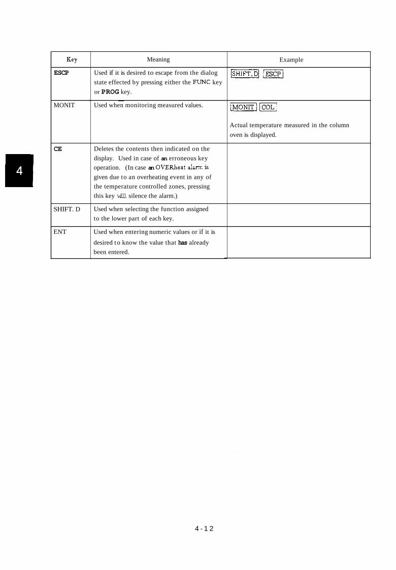
ESCP
MONIT
CE
SHIFT. D
ENT
Meaning
Used if it is desired to escape from the dialog state effected by pressing either the FUNC key or PROG key.
~
Used when monitoring measured values.
~~ ~
Deletes the contents then indicated on the display. Used in case of an erroneous key operation. (In case an OVERheat a h m is given due to an overheating event in any of the temperature controlled zones, pressing this key will silence the alarm.)
Used when selecting the function assigned to the lower part of each key.
Used when entering numeric values or if it is desired t o know the value that has already been entered.
Example
Actual temperature measured in the column oven is displayed.
4 - 1 2

3. Control Parameters and Default Values
The following Table h t s the reserved words of parameters available for control of the GC-l4B,
showing the parameters, maximum and minimum values avadable for input and their units. These
can be used for setting conditions from an externally arranged computer, via RS-232C or current
loop interface board (optional). Param- eter
DlRG
DlPL
DlCR
D2RG
D2 PL
D2CR
D3RG
D3PL
D3CR
D4RG
D4 PL
D4CR
FLW 1
FLW2
FLW3
FLW4
FLW5
INJT
DETT
AUXT
CITM
CITP
AITM
AITP
CPR 1
CPR2
CPR3
CPR4
CPR5
CFPl
CFP2
Meaning
DETECTOR 1 RANGE
I/ POLARITY
N CURRENT
DETECTOR 2 RANGE
N POLARITY
I, CURRENT
DETECTOR 3 RANGE
I/ POLARITY
N CURRENT
DETECTOR 4 RANGE
I, POLARITY
,/ CURRENT
FLOW CARRIER 1
N CARRIER 2
I/ H2 1
n Hz 2 /I AIR
INJECTION TEMP.
DETECTOR TEMP.
AUX. 2 TEMP.
COLUMN INITIAL HOLD TIME
COLUMN INITIAL TEMP.
AUXl INITIAL HOLD TIME
AUXl INITIAL TEMP
COLUMN PROGRAM RATE1
2
3 4
5
N
I,
N
N
COLUMK FINAL TEMP1
2 ,I
Max./&. values
0 , 1 . 2 , 3
2 (-1. l (+)
0 - 200
0 - 999.8
,I
I,
/I
0 - 399
0 - 399
0 - 399
0 -655
- 99.0-399.0
0- 655
- 99. w 399
0- 40.0
,,
,,
n
,
-99.0 -399.0
Unit
1 ox
mA, nA
rr
rr
rr
m C /min
N
N
N
I/
deg. "C
I,
min
deg. "C
min
deg. "C W m i n
n
I
I,
I
deg. "C N
Default value
40.0
40.0
30.0
30.0
200.0
200
200
200
0.0
100.0
0.0
100
0.0
I,
,/
,, ,,
200.0
0.0
4 - 13

%F- 1 Meaning 1 Max./Min.values 1 Unit 1 Default value
I
I,
N
- 7
CFP3
CFP4
CFP5
CFM 1
CFM2
CFM3
CFM4
CFM5
APRl
APR2
APR3
APR4
APR5
AFPl
AFP2
AFP3
AFP4
AFP5
AFM 1
AFM2
AFM3
AFM4
AFM5
TCDT
SNO
STRK
ISNO
FSNO
REPT
WASH
WSHT
TWTE
,,
I
min
,,
I
0. 0
,,
_ _ _ _ ~ _ _ _ _ ~ ~~
N 3
,, 4
5
COLUMN FINAL TIME 1
, 2
,I 3
4
,, 5
AUXl PROGRAM RATE1
I, 2
, 3
, 4
,, 5
AUXl FINAL TEMP1
I, 2
,, 3
4
5
AUXl FINAL TIME 1
N 2
,I 3
,, 4
N 5
TCD TEMP
SAMPLE NUMBER
STROKE
INITIAL SAMPLE NUMBER
FINAL SAMPLE NUMBER
REPEAT
WASHING LIQUID
WASHING TIME
TIME WAIT
PERIOD INJECTION 1 TIME
INJECTION2 TIME
FLOW K
DETECTOR TEMP MAX
1
49
1
1
I "
PROD IJ lT
IJ2T
FLWK
DMAX,
I "
0- 655 1 N
I N
I ,I
,,
0 - 250.0
I /I
-99.0 - 399
~ "
0 - 655
~ N
I ,I
0 - 399
0- 50
1 0- 80
0- 50
0- 50
1- 10 0 ( SAMPLE ) 1 SOLVENT )
1- 10
1, 2, 3, ...'... 10
0 - 655 0 - 10
0 - 10
0.01 - 999.8
10 - 450
I/
,
"C/min
0
N
I,
0.0
" I " I N
I,
deg. "C N
min
,,
I,
,,
200
0
I,
N
0.0
,,
i
deg."C 1 30
1 1
I I 1
l 5 min 1 10
deg. "C
4 - 14

param eter
CMAE
AMAI
HLDA
HLDC
SLPT
STRT
STPT
LDVC
STTS
FILE
STAR
STOP
FLM
AUXF
MON'I
SSTR
SSTP
DET 1
RT
SCAN
COPY
KLOK
CKSM
VALU
FNC $
DIGN
HOLD
ESCP
EVNT
LPRG LAOC
LPRM
AOC
PROG
Meaning
COLUMN TEMP MAX
AUXl TEMP MAX
HOLD AUXl
HOLD COLUMN
SLEEP TIME
START TIME
STOP TIME
LINK DEVICE
STATUS ( PRINT 1
FILE NUMBER
START
STOP
FLOW MEASURE
AUX. FUNCTION ( PRINT )
MONITOR
SHIFT DOWN START
SHIFT DOWN STOP
DETECTOR 1 ( PRINT )
RETENTION TIME (PRINT)
SCAN
FILE COPY
KEY LOCK
;HECK SUM
VALUE PRINT )
?UNCTION ( PRINT )
3IAGNOSTICS
<OLD
ESCAPE
EVENT
LIST PROGRAM LIST AOC PARAMETERS
LIST GC PARAMETERS
4 0 C i PRINT
PROGRAM
Max./Min. values
-99 - 400
-99 - 450
0 - 655
0.1 -3000
0 -3000
0 - 3000
0 - 55
0 - 9
0 - 9
1 ( UNLOCK )
1 ( L O C K )
2 ( INVERSE )
) ( O N ) . l ( 0 F F )
I ( INVERSE 1
0 - 255
Unit
,,
,I
min
I/
min
/I
Default value
400
/I
0.0
10
I
I
0
0
4 - 1 5
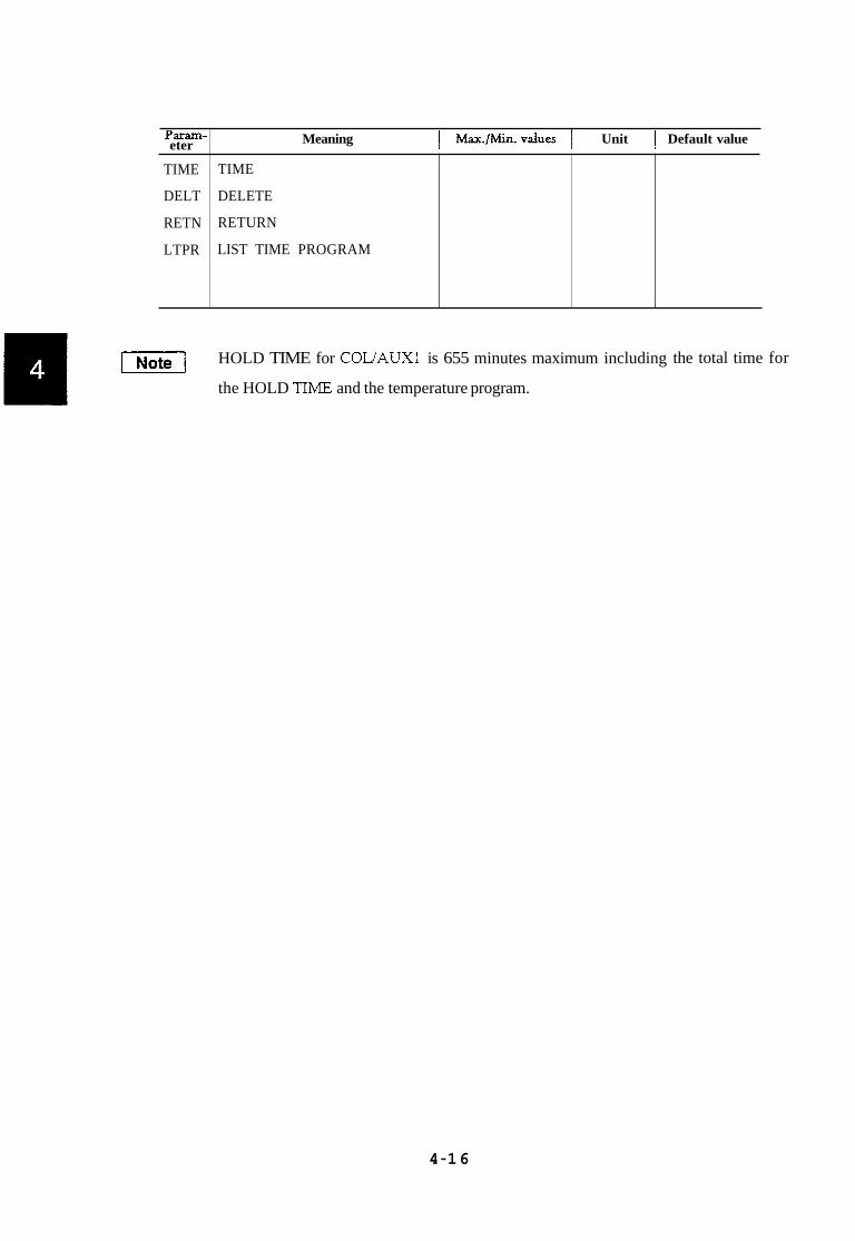
Yaram- eter Meaning I ~ = . / ~ i n . v d u e s 1 Unit 1 Default value
[Note/ HOLD TIME for COL/AUXl is 655 minutes maximum including
the HOLD TIME and the temperature program.
TIME
DELT
RETN
LTPR
the total time for
TIME
DELETE
RETURN
LIST TIME PROGRAM
4-16

4. Meanings of Indication Lamps
READY
(FINAL)
(RAISE)
(INITIAL)
COOL
Lights when the temperature in the column oven is stabilized within
+1"C of the setpoint. The time program and/or temperature program
and/or the AOC connected can be executed/operated. (START is
possible .)
Lights when the column oven temperature has risen to the next step and
is held there in the temperature program mode. In case of a single-stage
heating program, the temperature then equals the FINAL temperature.
Lights when the column oven temperature is in the course of rising.
Lights when the column oven temperature, reading within k1"C of the
setpoint, is in the initial HOLD in the heating mode, or the time program
or the AOC in use is at work.
Lights when the time of column oven FINAL temperature has elapsed
in the program mode, and remains lit till it stabilrzes at the initial
temperature. If the INITIAL and the COOL lamps hght simultaneously,
it indicates that the heating program of the column oven has terminated
and the AOC or the time program is now in the course of execution.
DIALOG Lights while the interactive operations are going on after pressing the
PROG key or FUNC key.
When this lamp is on, it means that the key to be pressed next is in the
SHIFT DOWN mode.
When this lamp is lit, it indicates that all the key operations are locked.
S. DOWN
LOCK
vl In the transition period fiom FINAL, to COOL in the program for the column oven, a
lamp other than COOL may light momentarily. This, however, can occur due to the
time lag that can be caused with these indication lamps, because of the time-sharing
software employed, and is not a symptom of failure.
0 2 1 DIALOG (INITAL) (RAISE) (FINAL) 0 I LOCK
I I - - n U U
READY COOL
4 - 17
u S- DOWN

5. Functionof Files
Ten files in all are made available from File Nos. 0 to 9, for accommodating such functions as
temperature setting for individual temperature controlled zones, temperature programs, setting
conditions for individual detectors, flow conditions, and time programs. Memory area for each file
is not fixed so that as much memory area as would be required can be occupied depending on the
size of each file. Therefore, the length of a time program may be made fairly long if the number of
files used is only a few. (Example: About 250 steps are available when the number of previously
opened files is only one.)
When a new file is opened, all of its contents are initialized bringing the time program for that
file to the blank state. Deletion of a file that has been opened is accomplished by operating the
Ii5EE-I key. It should be noted that no deletion can be executed of the presently used file.
If key operations are made as
If it is desired to copy the contents of the present file to another file, copying is accomplished by
[=I , File 3 is deleted.
using the lcopy[ key. If key operations are made as [SHIFT.] @ m] , contents of [ W W I I J
the present file are copied into File 4. In such a case, it is necessary that the file selected as the
destination for the copying should have never been opened before (that is, no setting has ever been
made in that particular file in the past.) Copying to a file that has been opened in the past should
be made by first deleting the contents in that file then by executing copying, otherwise, the contents
of the destination file may be corrupt.
(Ex.) Copy to an already used file (No.4) as follows:
Display of “LIMIT” appearing during operations to a file indicates that there is no reserve for
expansion of the file. In such a case, unwanted files need to be deleted to secure more memory.
I Note 1 Only one file can be designated at a time. Accordingly, in case of a change in file
number, the GC is controlled from the moment of the change according to the
contents of the file that has newly been selected. When temperature control operation
is going on in the GC, the setting temperature may change in some cases if another
file is selected inadvertently if the contents of that file have not been prepared
correctly. To avoid such trouble, new setting for several files or checking of their
contents should be done before pressing the I START 1 key. * When power is turned ON, the default file number selected is always 0.
4 - 18

6. Error Messages, etc.
OVER INJ
OVER AUX
Error Message displayed Contents
Injection port or detector temperature exceeds preset MAX. temperature.
Temperature of the oven controlled by AUXl exceeds present MAX. temperature.
I OVER COL I Temperature of the column oven exceeds preset MAX. temperature.
ERROR CR Trouble has occurred in the transmission of data between this unit and a Chromatopac data processing unit.
I ERROR CM 1 File contents changed during the period of power off.
~
ERROR 1
ERROR 2
ERROR 3
Error occurred in data transmitted or received.
Inability of measurement with externally arranged flow rate measuring device (optional item (optional item)
Operation error; no function available which corresponds to the one selected for input
SET. LDVC
NOT. LINK
I ERROR 4 I Operation error; value input is beyond the allowable limit.
~
When performing program listing, a number has not been set for the link device.
No linkage has been established between the 1/0 devices used for data transmission.
I
INITAL
No detector attached at the selected DET NO. Or switch on the detector control unit is in the off state.
Automatic initialization occurred as a result of a radical change in the data saved in the memory due to some reason such as lightning or freezing temperatures.
I CITP. XX I Temperature control has not been started yet. Appears at the time of power supply.
FAULT Given in case of partial destruction of the data in ROM. A service request is necessary is such a case.
Given when no extra space is available for expansion of a file, or if heating program has b been set for 6 or more stages. I I
4 - 1 9

22 1-4001 0-05
5. Operation 3
In this chapter, details of operation are described.

1. Temperature Setting
Contents
1.1 Outline
1.2 Temperature setting procedures
1. Column oven
2. Injector
3. Detector
4. AUXl
5. AUX2
6. TCD
1.3 How to look up a preset temperature
1.4 Heating program
1. Column oven
2. AUXl
3. Genera precautions
1.5 How to look up a preset program
1.6 Partial modification of program
1.7 Setting maximum temperature
1.1 Outline
This unit allows temperature control at six points in all, of which programmed heating is
possible for the column oven and for the AUXl. ____ -
This chapter describes in detail how temperature settings are made and how such heating
programs are prepared.
5 - 1
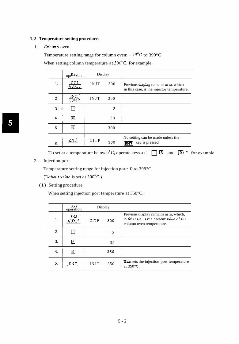
1.2 Temperature setting procedures
1. Column oven
Temperature setting range for column oven: - 99°C to 399°C
When setting column temperature at 3OO0C, for example:
operatlon Key Display
1.
2.
3 . 1 I
I N J T 2 0 0 Previous display remains as is, which in this case, is the injector temperature.
I N J T 200
3 1
5.
30 I Dl 300
Key Display operatlon
I. CITp 300
No setting can be made unless the
6. 1 1 C I T P 300 1 0 ENT key is pressed
Previous display remains as is, which, inthiscase,isthepresentvs~ueofthe column oven temperature.
To set at a temperature below OOC, operate keys a s " and 101 ", for example.
2.
3.
2. Injection port
3
0 35
Temperature setting range for injection port: 0 to 399°C
(Default vdue is set at 200OC.)
(1) Setting procedure
When setting injection port temperature at 350°C:
This sets the injection port temperature at 350°C. 5. I 1 I N J T 350 1
5 - 2

3 . Detector
Key. operatlon
Temperature setting range for detector: 0 to 399°C
(Default vdue is set at 30°C.)
Setting procedure:
When setting detector temperature at 100°C:
Display
1 wi I I N O O Previous display remains as is, which, in
this case, is the injection port temperature.
3.1 Dl I
5.
4 . 1 la I W] DETT 1 0 0 Now, detector temperature is set at 100OC.
1 0 0 I
Key. operaQon Display
4. AUXl
In this GC, temperature control of up to two auxiliary heating zones can be made, in addition
to that for the column oven, detector and the injection port. (e.g. for AUXl and AUX2)
Furthermore, programmed heating is made available for AUXl, in the same manner as for the
column oven.
Temperature setting range for AUX1: - 99°C to 399°C
Default vdue: Set at 100°C
Temperature setting procedure:
Ex. When temperature of AUXl is to be set at 150°C:
1. 1 -1 1 CITP 200
I I
1
5 - 1 0 I 1 5
150
Previous display remains as is, which, in this case,is the initial temperature of the column oven. S.DOWN lamp is lit when -1 key is pressed.
SHIFT.D lamp goes out.
Now, temperature at AUXl (initid temperature) is set at 150°C.
5 - 3

5. AUX2
Key. Display operatlon
I N J T 2 o o
2. 1x1 I NJ T 2 0 0
A heating block connected to AUX2 is controlled at a constant temperature; no program-
ming is possible.
Previous display remains as is, which, in this case, is the injection port temperature. SDOWNlampislitwhen this key operation is done.
S.DOWN lamp goesout.
AUX2 temperature setting range: 0 to 399°C
Default d u e : Set at 200°C
Setting procedure:
Ex. When setting AUX2 temperature at 150°C:
4.
5.
0 15
ml 150
2.
3.
4.
5.
6.
6. I m1 I AUXT 150 I Now, AUX2 temperature is set at 150OC.
- .
in this case, is the injection port INJT 2 O O temperature. S.DOWN lamp is lit when
this key is pressed. lml INJT 2 0 0 S.DOWN lamp goes out.
El 1
0 15
ml 150
[ENTI TCDT 1 5 0 Now, TCD temperature is set at 15OoC.
6. TCD
TCD temperature setting range: 0 to 399°C
Default value: Set at 200°C
(1) Setting procedure
Ex. When setting TCD temperature at 150°C:
Display Key. operatlon Previous display stiu remains as is, which,
5-4

1.3 How to look up preset temperatures
If you wish to look up the temperature set for a zone, you can get the value displayed by
effecting the following key operations. (Listing of preset values is also available.)
Key. operatlon
1.
2.
3.
4.
Display
Column
1.
2.
Previous display remains as is, which, in this case, is the injection port temperature. Preset value for injection port temper-
has been set at 2OO0C.
CITP 300
[mi I N J T 2 0 0 ature is displayed, which, in this case,
3. I 1 CITP 300
4.
Injection port
Preset value for AUXl temperature is
set at 150°C. AITP 150 displayed, which, in this case, has been
Previous display remains as is, which, in this case, is the injection port temperature.
Preset value for column oven temper- ature is displayed, which, in this case, has been set at 300°C.
Key. I Display I I overatlon
Detect or
Display operatlon ml I INJT 2 0 0 Previous display remains as is, which, in this case, in injection port temperature.
7 1 DET-T Preset value for detector temperature is displayed, which, in this case, has
I 1 1 been-set at 30°C.
AUXl
Previous display remains as is, which, in this case, is detector tern erature. S.DOWN lamp is lit when tlis key is pressed.
S.DOWN lamp goes out.
31 TEMP
5 - 5

5. AUX2
operaaon Key Display
1. 1 1-j 1 AITP 1 5 0
I I I
I Preset vdue for AUX2 temperature is
Previous display remains as is, which, in this case, is AUXl temperature.
I AUXT 250 displayed, which, in this case, has been set at 25OoC.
operaaon Kex
6. TCD
Display
3.
Previous display remains as is, which, in this case, in AUX2 temperature.
Preset vdue for TCD temperature is
set at 2 0 0 " ~ . TCD-T 200 displayed, which, in this case, has been
5 - 6

1.4 Heating program
Heating of the column oven can be executed by a desired multi-step heating program of up to
five steps.
1.4.1 Basic single-step heating
TEMP
B \
TIME 0
Parameters necessary to prepare the single-step heating program of the heating pattern shown
above are as follows:
unit
INIT TEMP setting temperature T1 "C
INIT TEMP setting time period a min
PROG RATE setting for T2- T1 " C/min
FINAL TIME setting time period c min b
FINAL TEMP setting temperature T2 "C
Key operations for inputting these parameters are done as foUows:
],,,lWJ [6110/ Iim
WlIIDlENT/
~ p n E l IENT/
/!a0 lENTl
~ ~ D l D l ~ E E l Through the above shown key operations, the necessary parametrs are set as shown below.
INIT TIME 10 minutes
INIT TEMP 60°C
PROG RATE 2. 5OCIrnin
FINAL TIME 15 minutes
FINAL TEMP 200°C
5 - 7

1.4.2 Heating in multi-steps (case of 3-step heating)
Initial state
1st step
2nd step
3rd step
In case of a multi-step heating program, necessary parameters are associated with respective
keys as shown below.
X 1 0 0 1 0 - Initial Temp, Time
5 1 5 0 5
Final Temp, Time
2 0 l 5 I 1 0 1 7 5
5 2 0 0
............... a
T, ...............
...............
............... c, e, g
............... Tz, T B ~ T4
200 -
It is recommended that a list be prepared as shown below to show all the necessary param-
eters to facilitate subsequent setting.
175 - / 15 -
0 10 20 25 42.5
~ 20 c
min 67.5
5 - 8

Key operations for inputting parameters are done as follows:
When preparing a multi-step heating program, one push of the m] key preceding inputs
for the parameters effect those parameters set for the 1st step of the program. Thereafter, each
round of parameter setting causes the steps to progress by one step without the need to push
[COLJ . Unless there is change in function selected, you can go on pressing relevant numeral keys,
followed with the pressing of the LENT] key repetitively, for one step after another, to load
a multi-step program.
In case of an erroneous loading of any of the parameters, a complete reloadmg from the
beginning is necessary for an erroneous entry on Program Rate. If, however, an erroneous
entry occurred for either Final Temp or Final Time, keep on pressing the m] key, without
pressing any numeral keys, until the value one step before the one to be corrected is indicated
on the display. When it appears on the display, enter the right value via numeral keys and then
press the key to effect the correction.
vl Effective time for a heating program is 655 minutes in total.
5 - 9

Preparing Heating Program
1. Column oven
(1) Setting initial temperature
The initial temperature is the temperature that has been set in section 1.2 "Column Oven"
Setting initid temperature HOLD time
Initial temperature HOLD time (Time period from START to the moment when the first
(2)
heating rise is started.)
Allowable setting range
Default vdue 0.0 min
Setting procedure
0 to 6 5 5 min
Ex. When initid temperature HOLD time for column oven is to be set at 20 min:
4.
I I
Initial temperature HOLD time for the column oven has been set at 20 minutes.
IENT( C I T M 20.0
Previous display remains as is, which, in this case, is the initial temperature of
(3) SettingPROG RATE
PROG RATES are set for each of the heating rises to be programmed for each step of
heating.
Allowable setting range:
Default v due :
Setting procedure
0 to 40.0°C/min
at O.O°C/min for each step
Ex. Column heating rate in step 1. at 5'C/min I1 step 2. at 2OoC/min
11 step 3. at 5"C/min
l l step 4. at 10°C/min
11 step 5. at 20°C/min
5 - 1 0

ODeratlOn Key Display
1 CITM 20.0
PROG RATE 3 for the column oven is set at 5.0°C/min. 8 1 1 CPR3 5.0 1
Previous dis lay remains as is, which, in
time for the column oven. this case is t x e initial temperature HOLD
PROG RATE 4 for the column oven is set at 10 .0~~ /min . 10 I 1 CPR4 10.0 I
3
4
5
6
7
PROG RATE 5 for the column oven is set at 20.0°~/min. 12 I “T_] 1 CPR5 20.0 1
5
PROG RATE 1 for the column oven is IENT/ CPR1 5.0 set at 5.0°C/min.
El 2
a 20
PROG RATE 2 for the column oven is IENTl CPR2 20.0 set at 20.00c/min.
0 5
1 I 1
1-1 From then on, even if numerals are input followed with pressing of the mi key, no
changes occurs in the display, etc., as the limit of the steps for P.RATE has been
reached.
(4) FINAL TEMP
This sets the final temperature for each step in the programmed heating. The final tem-
perature set for a step means the starting temperature for the next step in the heating
program. It does not matter if the final temperature set for a step is lower than that for the
preceding step.
Allowable setting range:
Default value:
- 99 to 399°C
at 200°C for FINAL TEMP 1, others are set at 0°C
5 - 1 1
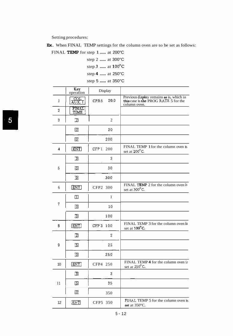
Setting procedures:
Ex. When FINAL TEMP settings for the column oven are to be set as follows:
FINAL TEMP for step 1 ..... at 200°C
step 2 ..... at 300°C
step 3 ..... at 1 0 0 " ~
step 4 ..... at 250°C
step 5 ..... at 350°C
12
I I Display operation
lENTJ CFP5 350
3 1 a I 2
4 1 1 CFPl 200
6 1 1 CFP2 300
7 1 I 10
10 1 1 CFP4 250
I D 1 350
Previous dis lay remains as is, which in this case is t i e PROG RATE 5 for the column oven.
FINAL TEMP 1 for the column oven is set at 200'~.
FINAL TEMP 2 for the column oven is set at 300'C.
FINAL TEMP 3 for the column oven is set at IOO"C.
FINAL TEMP 4 for the column oven is set at 250'C.
FINAL TEMP 5 for the column oven is set at 350°C.
5 - 12

(5) FINAL TIME
Sets find temperature HOLD time for each step in the programmed heating.
0 to 655 rnin
0.0 min for all steps
Allowable setting range:
Default value:
Setting procedure:
Ex. When setting FINAL TIMES for the steps as follows:
Step 1 ..... at 30 min
Step 2 ..... at 0 min
Step 3 ..... at 20 rnin
Step 4 ..... at 0 min
Step 5 ..... at 60 min
1
operatlon Key: Display
Previous dis lay remains as is, which in th+ case is tge FINAL TEMP 5 for the CFP5 350
I column oven.
3 1
9
I I
FINAL TIME 3 for the column oven is CFM3 20.0 set at 20.0 min. [rnj
30 I
11
FINAL TIME 1 for the column oven is set at 30.0 min.
5 1 m] 1 CFMl 30.0 1
FINAL TIME 4 for the column oven is set at 0.0 min.
CFM4 0.0
6 1 a I O I FINAL TIME 2 for the column oven is set at 0.0 min.
7 1 (ENTI I CFM2 0.0 I
1 0 1 a j O I
12 } I I
FINAL TIME 5 for the column oven is set at 60.0 min. 13 1 IENT/ I CFM5 60.0 1
5 - 13

2. AUXl
Key. Display operatlon
1 [=D] C I T P 100 Previous display remains as is, which in this case is the INIT TEMP of the column oven. -
I I
5 AITM 3 0.0 INIT TIME for AUXl is set at 30 min.
(3) SettingPROG RATE
Allowable setting range:
Default value:
0 to 250.0°C/min
O.O°C/min for all steps
Setting procedure:
Ex. When setting PROG RATE for the steps as follows:
Step 1 ..... at 10°C/min
Step 2 ..... at 20°C/min
Step 3 ..... at 5*C/min
Step 4 ..... at 2.5"C/min
Step 5 ..... at 10°C/min
5 - 14

Key: oDeranon
1 I [SHIFT.] I AITP 100
Display
4 l o / 1
10
5 1 JENT] 1 A P R l 10.0
6 1 I 2
2 0
7 1 1 APR2 20.0
8 l I 5
9 I I APR3 5.0
11 1 m] 1 APR4 2.5
1 1 APR5 10.0
Previous display remains as is, which in this case is the INIT TEMP for AUX1.
PROG RATE 1 for AUXl is set at 10.0"Clmin.
PROG RATE 2 for AUXl is set at 20.0°c/min.
PROG RATE 3 for AUXl is set at 5.0"Clmin.
PROG RATE 4 for AUXl is set at 2.S0C/min.
PROG RATE 5 for AUXl is set at lo.ooc/min.
5 - 1 5

(4) Setting FINAL TEMP
Allowable setting range:
Default value:
Setting procedure:
- 99 to 399°C
O°C for all the steps except step 1 which is set at 200°C
Ex. When setting FINAL TEMPS for the steps as follows:
Step 1 ..... at 2 0 0 " ~
Step 2 ..... at 300°C
Step 3 ..... at 1 0 0 ~ ~
Step 4 ..... at 15OoC
Step 5 ..... at 3OO0C
operanon Key. Display
Previous display remains as is, which in 1 11-1 1 APR5 10.0 lrhis case is the PROG RATE 5 for AUX1.
3
4
5
El 2
20
Dl 200 FINAL TEMP 1 for AUXl is set at AFPl 200 2oooc.
a 3
Dl 30
7 1 I
8
El
1 0 0
AFP o o FINAL TEMP 3 for AUXl is set at 10oOc.
1
9 1 El I 10
15 1 FINAL TEMP 4 for AUXl is set at AFP4 150 1500c.
El 3
11 30
AFp 5 300 "TI
5 - 16
FINAL TEMP 5 for AUXl is set at 30OoC.

0 to 6 5 5 rnin
0 min for all the steps
Key operation
Setting FINAL TIME
Allowable setting range:
Default value:
Setting procedure:
Ex. When setting FINAL TIMES for the steps as follows:
Step 1 ..... at 10 min
Step 2 ..... at 0 min
Step 3 ..... at 30 rnin
Step 4 ..... at 20 min
Step 5 ..... at 20 min
Display
1 [SHIFT.DJ A F p 3 0 Previous display remains as is, which in this case is the FINAL TEMP 5.
! Q l 0
4
l o I 1
FINAL TIME 1 for AUXl k set at 5 1 I A F M l l o . o ! 10 min.
7
4 Dl I FINAL TIME 2 for AUXl is set at mi AFM2 0.0 omin.
O I
9 30.0 FINAL TIME 3 for AUXl is set at 30 min. “TI AFM3
3 1
11
Dl 2 0
FINAL TIME 4 for AUXl is set at [m] AFM4 20.0 2 ~ - .
30 I
13 20, FINAL TIME 5 for AUXl is set at 20 min. IENT/ AFM5
12 I I I I I
2 o I
5 - 17

3 . General precautions
ICOLI and \mJ keys
I t has been described, in setting for a heating program, that either the key or [ml key should be pressed first to designate whether the setting is for the column oven or for AUXl
(by pressing jSHIFT.D]and keys for AUX1. Refer to the relevant paragraphs on
column oven temperature and AUXl temperature.)
Either of these two keys, however, remains effective, once pressed, till the other one is
pressed. If setting is being done for the column oven, for example, you don't have to press the
ml key each time you set for PROG RATE or FINAL TEMP, but you may press directly
either the 1'"""1 or ml key. RATE
Key. oDeranon Display
Previous display remains as is, which in this case is the initial temperature of AUXl. T h i s remains effective till next operation AITP 1 0 0 is performed as m. (or, tiu some other operation is
1 & 1 and
performed for AUX1.)
AITP 1 0 0
1 3.
4. 10
Setting for initial temperature HOLD t ime for the column oven. C I T M 10.0
C I T M 10.0
5
C P R l 5.0
0 Setting PROG RATE for the column oven.
9. C P R l 5.0
10. 2
11. 20
12.
13. Setting FINAL TEMP for the column oven.
C F P l 200
5 - 1 8

Once either the column oven or AUXl is selected, no change occurs in that status till the other
one is selected.
3.
Key. I ODeratlon
ml CITP. 1 0 0
Display
4.
1. 1 1 CITP. 1 0 0
CITP 1 0 0
Previous display remains as is, which in this case is the initial column oven temDerature.
5. m] CITP 100
2- INITIAL INIT ITEMPI
2. 1 1 CITP. 100 Column oven is selected by this operation.
Observation of the setting of the initial temperature of the column oven.
Observation of the initial temperature HOLD time for the column oven.
6. I LENTI I CITM 5.0
7. I [MoNITI CITM 5.0
.%DOWN lamp lights.
AITP. 150 Now, the temperature of AUX.1 is monitored. But, this is not the operation for selecting AUX.l status.
10. 1 L-1 I AITP. 150
PROG RATE for the column oven is displayed. C P R l 3.0
Precautions for programming
In preparing a temperature program, for example, while programming for heating the column
oven, you can proceed to set for INIT TEMP, INIT TIME, PROG RATE, FINAL TEMP and
FINAL TIME in an optiondy selected sequence.
Key. I operatlon Display
I 1 INITIAL Previous display remains as is, which in this case is the initialized state.
~~~
INIT TEMP ..... 100DC 4. I I CITP 100
5- I CITP 100
1 1 0
5 - 1 9

- 7.
8. -
CITM 10.0 INIT TEMP HOLD t ime ..... 10 min
m CITM 10.0
5 9.
10.
11.
-
-
- 12.
13. -
C P R l 5.0 PROG RATE 1 ..... 5°C
1
10
jENTl C P R 2 10.0
C P R 2 10.0
14.
- 15.
16. -
1 15
1 5 0
El 0 Dl
~
C F P l 150 FINAL TEMP 1 ..... 150°C
2 20
2 0 0
17.
18.
19.
-
-
C F P Z 2 0 0 FINAL TEMP 2 ..... 200°C
Dl
C F P Z 2 0 0
1 1 0
20. "T1 C F M l 10.0 FINAL TEMP 1 ..... 10.0 min
21. 0
22.
23, -
FINAL TEMP 2 ..... 0.0 min C F M 2 0.0
3 3 0
24. CFMS 30.0 FINAL TEMP 3 ..... 30 min
25. CFMS 30.0
26.
27, - 0 5
C P R 3 5.0 PROG RATE 3 ..... 50°C
28 C P R 3 5.0
29 1 1 5
1 5 0
El 0 Dl
30 FINAL TEMP 3 ..... 150.0"C C F P 3 150
5 - 20

Even if other operations as for setting INJ temperature, for example, are done midway in
the programming operation, the parameter set can be programmed for the next step succeedmg
the one for which a setting has been made, if any one of the program parameters is keyed 1
in. By pressing key, for example, the next F.TEMP step can be programmed.
key, e.g., I t should be noted, however, that any key operations prefixed by the Ki COL
Key operatxon
rendering the subsequent setting as starting with step 1.
If the “LIMIT” message should appear in the display in the course of setting, it indicates
Display
that setting has exceeded the limit of the five steps allowed. For example, if further key-in
2.
operation is performed by pressing TEMP
been made up to CFP5, a “LIMIT” message is displayed.
lm] , while settings have already IFINAL/ However, if you tried to set FINAL TEMP by pressing the [ml key only right after having
set CFP5, for example, immediately before it, no such “LIMIT” message appears, as shown
El
El
below.
2. El
El
I I I
3.
4.
5.
1. 1 El 1 C P R 5 10.0 /Pre~ousdispiayremainsuis.
CFP5 300 SeningforFINAL TEMP5
3
350 El 35
Display does not change, with nothing being set indicating that it is a setting iptended for a step beyond the allowable 5 steps.
IENT] 3 5 0
3 30
3 0 0
5 - 21

1.5 How to look up a preset program
If you wish to look up the contents of the preset program, proceed as follows.
Column oven heating program
(1) INIT TEMP (Ini td Temperature)
1
Key. Display operatlon m] INJT 20 0 this case is the injection port temperature Previous display remains as is, which in
which has been set at 2OOOC.
3 @EI
(2) INIT TIME (Initial Temperature HOLD Time)
Preset initial temperature of the column 'ITP l o o ovenisdisplayed.
Key Display operatlon
m] INJ .
3 IENT] CITM 10.0
( 3 ) PROG RATE
Previous display remains as is, which in this case is the injection port temperature which has been set at 200°C.
Preset INIT TIME ( I n i d temperature HOLD time) is displayed, which in this case has been set at 10 min.
operatron Key. Display
k@d 'ITM Previous display remains as is, which in this case is the INIT TIME.
3
4
5 - 22
PROG RATE 1 is displayed, which in this case has been set at 5.0°C/min.
IENT] C P R l 5.0
C P R 2 10.0 PROG RATE 2 is displayed.
5
6
7
C P R 3 5.0 PROG RATE 3isdisplayed.
C P R 4 2.5 PROGRATE4isdisplayed.
"T] C P R 5 0.0 PROG RATE 5 isdisplayed.

(4)
(5)
5
FINAL TEMP
C F P 3 1 5 0 FINAL TEMP 3 is displayed.
6 " T ] C F P 4 250 FINAL TEMP 4 is displayed.
Key I Display I I oDeranon
operanon Key
Previous display remains as is, which in this case is PROG RATE 5.
COL
Display
FINAL TEMP 1 is displayed, which in this case has been set at 20OoC. 3 1 1 C F P l 200 1
4 1 1 C F P 2 250 1 FINALTEMP2isdisplayed.
7 I I C F P 5 0 1 FINAL TEMP 5 is displayed.
FINAL TIME
Previous display remains as is, which in this case is FINAL TEMP 5.
FINAL TIME 1 is displayed, which in this case, has been set at 0.0 rnin.
3 1 1 C F M l 0.0 1
5 1 1 C F M 3 30.0 1 FINALTIME3isdisplayed.
6 I I C F M 4 0.0 I FINALTIME4isdisplayed.
7 I I C F M 5 0.0 I FINAL TIME 5 isdisplayed.
AUX. 1 heating program
Contents of the heating program can be looked up in the same manner as described above.
In this case, key operation is to be made as , instead of the pressing of only
the ml key. Formats of displays given to indicate the initial temperature, etc. are as shown
below. . __
AUX.l INIT TEMP ................. AITF'
INIT TIME ................. AITh4
PROG RATE 1-5 ..... APRl - 5
FINAL TEMP 1- 5 ..... AFP1- 5
FINAL TIME 1 - 5 ..... AFMl - 5
5 - 23

Precation: key
C F P l 150
C F P 2 250
As was described in the section on how to prepare a heating program, key-in operations as
FINALTEMP1
FINALTEMP2
, or as EJ ml, or lxjm , ..... etc. cause
22
23
respective displays to be returned to the first step in the heating program. Therefore, the
following operations are also possible, fore xample:
rn m]
1
2
3
4
5
6
7
8
9
10
11
12
13
14
15
16
17
IENT]
"TJ
IENT]
LENT]
By pressing the
20 I FINAL
21 1 L]
Display
C I T P 1 0 0
CITM 10.0
C P R 1 5.0
C F P 1 1 5 0
C F M 1 0.0
C P R 2 10.0
C P R 3 5.0
C F P 2 2 5 0
C F P 3 1 5 0 1
Display is cleared.
INIT TEMP
INIT TIME
PROG RATE 1
FINAL TEMP 1
FINAL TIME 3
PROG RATE 2
PROG RATE 3
FINAL TEMP 2
FINAL TEMP 3
3 key here, display returns again to step 1.
C P R l 5.0 PROG RATE 1
5 - 24

1.6 Partial change to a program
If partial change to the heating program is required, proceed as follows.
Ex. When column FINAL TEMP 3 is to be changed to 15OoC, and FINAL TIME 2 is to be
changed to 20 min.
1
2
3
4
5
6
7
8
9
10
11
12
13
Display
CITP 1 0 0
C F P l 150
C F P 2 2 5 0
1
15
150
C F P 3 150
C F M l 0.0
2
20
CFM2 20.0
Previous display remains as is, which in this case, is the INIT TEMP of the column oven.
FINAL TEMP 1 is displayed.
FINAL TEMP 2 is displayed. Key in the desired value while the item just before the one to be changed is still displayed.
FINAL TEMP 3 is set at 150°C.
Key in desired value in the same manner while the item just before the one to be changed is on display.
FINAL TEMP 2 is set at 20 min.
1 Note ] Once PROG RATE is set, the PROG RATE for the next step is automatically set at
O"C/min.
This is to prevent an unwanted heating rise to be executed if the value in the new
program is smaller than that in the previous program in preparting the heating
program. (No heating is performed for the step if the PROG RATE for the step has
been set at OWmin.)
Accordingly, in case of a partial change attempted in the PROG UTE, it is necessary
to set all the PROG RATES again for the steps following the step for which the PROG
RATE has been changed.
5 - 25

1.7 Setting the maximum temperature
For both the column overn and the AUX.1, it is possible to set the upper limits for their tempera-
tures. Temperature control will stop if the temperature in either of these parts should exceed the
preset upper limit.
(1) Maximum value for column oven temperature
Maximum value for column temperature can be set within the range of -99°C to 40OoC.
(Default value: 400°C) If the column oven exceeds the preset maximum value, the “OVER
COL” warning message appears on the display, and the buzzer sounds continously and heating
with the oven heater is stopped. To release this, either press the key when the column
oven temperature has fallen sufficiently, or set the maximum value for the column oven tem-
perature at a new value which is higher than the present column oven temperature, and then
Key. operaaon
pressthe key.
Display
Setting procedure (for setting at 350°C)
3
4
5
El 7 %DOWN lamp goes out.
CMAX 50 Displayed is the max. value then set for column oven temperature. DIALOG lamp is lit up.
3
Previous display remains as is, which in this case is the column temperature that has been set at 300°C.
6
I‘ 1-
IIFUNCI I
I3 35
I s.DowN lamp is lit up.
8 Now, the upper hitofor column oven tem- perature is set at 350 C, with display shifted one function forward in the list.
LDVC 1 1
10
I I I
While the display remains as is, the DIALOG lamp goes out. psm]
7 1 I 3 5 0 1
5 - 26

(2) Maximum value for AUX. 1 temperature
Maximum value for AUX. 1 temperature can be set within the range of -99°C to 450°C.
(Default value: 400°C)
If AUX.1 temperature should exceed the preset maximum value, the “OVER AUX” warn-
ing appears on the display and the buzzer keeps on sounding. At the same time, heating
with the heater is stopped. To release this condition, press the key when the temper-
Key. oDeratIOn
ature of AUX. 1 has fallen sufficiently, or set a new value, which is higher than the present max.
Display
AUX. 1 temperature, as the revised max. oven temperature, and press the /CEI key.
Ex. When setting the upper limit for AUXl temperature at 350°C:
Wl EJ
F]
Last display remains as is, which in this caSe is the INIT TEMP set for AUX.l. 50
s.DowN lamp is lit up.
S.DOWN lamp goes out.
6
Set vdue for max. AUXl temperature is dis- played, with the DIALOG lamp lit up. Skip to step 9 if no change is desired for the value.
AMAX 2 0 0
7
9
5 1 I
Dl 350
35OoC is set for the max. AUXl temperature,
in the list.
S.DOWN lamp is lit up.
8 m CMAX 4 0 0 with display shifted one function forward
lsHIFTl
3 1 35 I
1 Both DIALOG and S.DOwN lamps go out.
Operations 9 and 10 are intended to let you escape from the DIALOG mode, hence they are
musts before performing other operations.
5 - 27

2. Detectors
ODeratlon Key.
Contents
Dispby
2.1 Outline
2.2 Selecting a particular detector
2.3 How to look up the selected detector
a. To look up the number of the detector then selected
b. To identify the type of detector corresponding to the assigned detector number
2.4 RANGE, POLARITY and CURRENT
1
2.1 Outline
Five different types of detectors, e.g. FID, TCD, FTD, FPD and ECD, are available for con- E
-~ ~
The last display remains as is, which in this case is the column oven temperature, which has been set at IOOOC.
C I T P 1 0 0
nection with this unit. Matching these different types of detectors with particular numbers
selected from among DETECTOR 1 to 4 has been determined beforehand on the detector PC
board, at the time of shipment or installation of the unit.
3
2.2 Selecting a particular detector
Selection must be made as to which one of the detectors provided for the unit is to be used for
the analysis.
DET 4 Now, detector 4 is selected. If a TCD is con- nected as DETECTOR 4, for example, the TCD is selected as the detector for use.
4 1
5 - 28

2.3 How to look up the selected detector
a. To look up the number of the detector presently selected
1.
operanon Key Display The last display remains as is, which in
I N J T 2 0 0 this case is the iniection ~ ~ r t temperature,
2.
I Note I When performing this operation, if the display given already consists only of a
number, that value is set for the DETECTOR No. To avoid this, such a display should
be cleared beforehand by pressing the a key.
which has been sit at 202C.
The number assigned to the selected DET 4 is displayed, which in this case is
DETECTOR 4.
operation Key =Play
2 1.
2. 1 I DET 2
[DETI A numeral key, e.g. key 2 ii~ this case, was pressed before this operation with 2 remaining on the display.
Now, DETECTOR 2 is set.
1
b. To identify the type of detector with the assigned detector number (from among DETECTOR
Nos. 1 - 4)
operation Key Display
1-J INJT 2 0 0
2
3
INJT 200
i2 2 Enter DETECTOR No. 2.
4
5 - 29
FID Indicates that DETECTOR 2 is FID.

2.4 RANGE, POLARITY and CURRENT
a. Setting procedure
After selecting a particular one of the detectors, RANGE, POLARITY and CURRENT are
set for the detector (as applicable).
Ex. Setting POLARITY
3.
I operagon Ke I Display I
Now, “l” is set as the POLARITY of DETECTOR 4. (That is, signd is output as positive when sample is injected into the injection port at side 1.)
D 4PL
The last display remains as is, which in this case is selection of DETECTOR No. 4. 1. 1 1 DET
vl If only the numeric value entered remains in the last display appearing after these key-
in operations, it indicates that no parameter settings have been made for that particular
detector. In such a case, some other necessary parameters settings must first be made
for the detector.
If you attempt to set kwith any value that is beyond the allowable setting range
specified for the detector (in this regard, please refer to the section concerning these
detectors), an “ERROR 4” message appears on tr.5 display, with no change occurring
from the last setting value.
In case of a setting for RANGE, P9LARITY or CURRENT, attempted for a
DETECTOR No., to which no detector is connected, or in case of a setting attempted
for such an item that is prohibited for that detector, (refer to the section on Detectors)
a “NON” message will appear, telling that such a setting is not possible for that
detector or the detector doesn’t exist (the switch might be OFF).
5 - 30

3. Starting and Ending Temperature Control
Contents
3.1 O u t h e
3.2 Starting and ending of temperature control
3.3 Timer functions
(1) SHIFT DOWN START
. (a) Setting
(b) Execution
(2) SHIFT DOWN STOP
3.4 Monitoring of SLEEP time
3.1 Outline
Upon completion of settings for temperature, temperature control operation is started. At this
time, the starting and the ending times can be set for the intended temperature control.
3.2 Starting and ending temperature control
By pressing the -1 key, controlled heating and holding operations are started at each
of the temperaturecontrolled zones, toward the respective setpoints. For the column oven and
the AUX. 1, temperature control is executed at their respective INIT Temps. The READY lamp
lights up when the column oven temperature has become settled within -tl"C of the set value.
3.3 Timer functions
Starting and ending the temperature control can be done automatically by utilizing the follow-
ing timer functions.
(1) SHIFT DOWN Start
This operation is performed when it is desired to start the temperature control after a certain
time delay, while no present temperature control is being done.
(a) First, the START TIME is set, which is the time period desired before starting the temper-
ature control. Duration of this START TIME is set at the default value of 10 minutes at
the time of turning on power. It can be set at a desired value within the range of 0.1 min
to 3000.0 min. It should be noted that the START TIME appearing on the display is the
value obtained by counting fractions over 5 as the unit and disregarding the rest in tenths
5 - 3 1

place. For example, if it is set at 0.1 min, display will appear as START TIME “0”, but
actually it is set exactly at 0.1 min (or 6 seconds).
(Ex. When setting START TIME at 10 hr)
3.
4.
5.
6.
The last display remains as is, which in
S.DOWN lamp is lit.
6
60
Dl 60 0
IENT] STRT 6 0 0 600 min (10 hr) is set for START TIME.
I I I
operanon Key. Display The last display remains as is, which in
(b) Execution
1.
2.
The following key operations are to be performed to get the temperature control started
[ - I CIT p 00 this case is he-column oven INIT TEMP, which has been set at 100°C. S.DOWN lamp is lit. Display changes to read as shown on the
last for the time set for the START TIME. 1-j SLEEP left, entering a WAIT condition, which
after the expiration of the START TIME in actual operation.
I I I
Temperature control starts when the * * I time set for the START TIME has expired.
If the above key operations are performed while the temperature control is going on,
illumination of READY lamp goes out momentarily with display changing to read “SLEEP”.
But, the temperature control is resumed immediately thereafter, with the display appearing
as “**”.
I Note 1 Execution of these key-in operations while the heating program is going on brings
about a HOLD state, with the counting of retention time being suspended. To leave
this state, either press the 1-1 key, or press the -1 key again. Note that,
upon completion of the execution of the program, display changes to “**”.
5 - 32

(2) SHIFT DOWN Stop
While the temperature control is going on, it can be suspended temporarily after a certain
period of time and then can be resumed for continued operation.
(a) Setting
First, the STOP TIME (the time period up to the moment when the temperature control
is to be suspended) is to be set. The default value for the STOP TIME 10 min, and it can
be set within the range from 0.1 to 3000 min. Setting can be made down to the tenths
place, but in such a case, the value on the display wil l appear by counting fractions over 5 as
the unit but disregarding the rest.
Ex. When setting STOP TIME at 5 hr
operatxon Key Display
1. The last display remains as is, which in this case is the column oven INIT TEMP. S.DOWN lamp is lit up.
1-1 C I T P 1 0 0
Next the SLEEP TIME (the time period during which the temperature control is to be
suspended) is set, which lasts for 10 min as the default value.
SLEEP TIME can be set as desired within the range from 0.1 to 3000 min. I t may be set
down to the tenths place, but the value appearing on the display is rounded off by counting
fractions over 5 as the unit but disregarding the rest.
2.
3.
4.
5.
6.
5 - 33
~- =I CITP 100 S.DOWNlampgoesout.
3 3
E l 30
3 0 0
STPT 3 0 0 5 hr (300 min) is set for STOP TIME.

Ex. When setting SLEEP TIME at 12 hr
Key. operanon Display
The last +lay remains as is, which in 1. 1-1 I N J T 2 0 0 this case is the injection port temperature.
S.DOWN lamp is lit up.
If you attempt to set a value beyond the allowable limit for the setting, an “ERROR 4”
message appears with no change occurring in the previously registered value.
(c) Execution
The following key operations are to be performed to have the operations of stopping and
starting of temperature control executed in actual operation.
2.
3.
4.
5.
6.
1.
1x1 INJT 2 0 0 S.DOWN lamp goesout.
El 7
El 7 2
D 7 2 0
SLPT 7 20 12 hr (720 min) is set for SLEEP TIME.
2.
Key oDeranon Display
The last display remains as is, which in this case is the INIT TEMP of the column oven. S.DOWN lamp is lit up. 4 SLEEP
Message as shown on the left appears on the display, and temperature control is carried out for the mriod as has been set for STOP TIME.
After the expkation of the time set as the STOP TIME, display changes to read as shown on the left, and the temperature con- trol stops. Remains in standby for the period of time as has been set for the SLEEP TIME.
I
Temperature control is resumed after the time set for the SLEEP TIME has expired.
* *
I
No change occurs if the above operation is executed while temperature control is not
going on.
If the -1 key is pressed to have the program executed while in the WAIT state
(standby) while performing temperature control, execution of the program is started and it
is kept on to the last even if the preset STOP TIME expires before the completion of the
5 - 34

program, i.e., the START key has priority override. If the set STOP TIME has not expired
yet even when the program has come to the end, the GC remains in standby while perform-
ing temperature control, with READY lamp remaining lit. If the STOP TIME has expired
already, the temperature control terminates at once.
If SHIFT DOWN STOP operation is made while the heating program is going on, the
situation is a little different from that described above; counting of the STOP TIME starts
after completing the execution of the program. Therefore, the temperature control comes
to a stop when the STOP TIME has expired after the completion of execution of the program.
Key. operatlon
2. -1
Display
The last display remains as is, which in this case is the set value of the injection port temperature.
I NJ
I N J T 2 0 0 S.DOWN1ampishup.
sLpT- SLP-T
Temperature control starts when the preset SLEEP TIME has expired, but the display remains
on without clearing even after the temperature control has started.
If this operation is performed during the WAIT time which spans from the SHIFT DOWN STOP
operation to the completion of temperature control, then the current count of the STOP TIME at
that moment is displayed. (Be careful, however, in that the display appears as “SLPT.
The temperature control stops when the preset STOP TIME has expired, then display is reset to
“0” and counting of SLEEP TIME is started.
”.)
S.DOWN lamp goes out. Current count of SLEEP TIME is dis- played in minutes, with the display ad- vancing in increments of one minute.
5 - 3 5

4. Operations Performed During Analysis
Contents
4.1 Outline
4.2 Starting analysis
(1) START (1)
(2) START (2)
( 3 ) Case of heating AUX. 1
4.3 Operations performed during measurement
(1)
(2) HOLD
Monitoring the temperature for each temperature controlled zone
a. HOLDing temperature
b. HOLDing retention time
c. HOLDing AUX.1
(3) Monitoring retention time
(4) Monitoring program
( 5 ) Others
operatlon Key
4.1 Outline
After all the settings necessary for analysis have been completed, including column oven
temperature, heating program, setting for the detector, etc., actual analysis is started. Various
operations are possible during analysis.
Display
4.2 Starting analysis
(1) START (1)
By pressing the m] key, temperature control is started.
1. -1 * * Starting temperature controL
5 - 36

By pressing the p] key, the column oven (and also the AUX.1, if it is connected) is
controllably heated to the temperature set as the INIT TEMP. Also, the injection port and the
detector (and the TCD and/or AUX.2 as well, if such options are connected) are heated to and
controlled at their preset temperatures.
The READY lamp is lit up when the column oven temperature has reached and settled
within k1”C of the set temperature. The temperature may fluctuate sllghtly before the column
oven temperature has stabilized causing the READY lamp to be turned off once or twice, but
this is stabilized soon afterwards.
(2) START (2)
By pressing the [m\ key once again, the heating program is executed and the analysis
is started.
1. I -1 1 RT. 0.0 0 Retention t ime is displayed in “min”.
o Case of heating the column
If this operation is performed before the column has reached the preset INIT TEMP, the
heating program and/or the time program are started in the absence of the normal temper-
ature control.
If the -1 key is pressed, execution of the heating program is started even when
the detector temperature has not reached the setpoint yet, To avoid such trouble, be sure
to check the detector temperature to see if it has reached the setpoint before starting
operation.
Progress of the execution of the heating program can be monitored with the lamps provided
on the control panel; fitst, when the step is entered, where the column oven temperature is
held at the set INIT TEMP, the READY lamp goes out and the INITIAL lamp is lit up instead.
The RAISE lamp is lit when the heating step is entered, and the FINAL lamp is lit when
that rise is completed, where it is to be held at the FINAL TEMP in the heating process
(FINAL TIME). When entering the next heating cycle, the RAISE lamp is lit again, and the
FINAL lamp is lit when arriving at the FINAL TEMP step.
These processes are repeated as many times as have been programmed. In case of a heat-
ing process, where the FINAL TEMP for the step is set at a lower temperature than the
START TEMP for the next step, however, the RAISE lamp lghts momentarily but it is
5 - 37

replaced with the lighting of the FINAL lamp soon thereafter, and temperature starts falling
at that moment. (As described already in the section on the Heating Program, the FINAL
TIME step sets in at that moment. Therefore, the FINAL TIME for the step should be
provided sufficiently long enough to allow for the s tabhat ion at that FINAL TEMP for
the step.)
When the heating program has come to the end (if the PROG RATE for the next step has
been set at O.O°C/min, it is judged to be the end of the heating program.), the COOL lamp
lights and the column oven temperature is lowered to the INIT TEMP set for the column
oven. At the same time, counting of retention time terminates, and the READY lamp lights
when the set INIT TEMP is reached.
Even when the FINAL TEMP for the last step is lower than the INIT TEMP set for the
column oven, the COOL lamp lights upon completion of execution of the program. In this
case, however, the column temperature continues rising even after the COOL lamp lights, to
return to its INIT TEMP.
(3) Case of heating the AUX.l
Heating is carried out in the same manner as for thecolumn oven, but no facility for monitor-
ing status with indication lamps is provided.
2.
4.3 Operations during measurement
(1) Monitoring of temperature
Temperature of the column oven at that time is CITP. 122 displayed prefixed by “CTTP”, but that does not
show the INIT TEMP set for the column oven. It can be differentiated from the INIT TEMP set- ting with the flashing “period” sign appearing
Current temperature at each of the temperature control points can be monitored during
measurement.
operanon
Display operanon I
Display
The last display remains as is, which in ‘ITP- 122 this c s e is the column oven temperature.
The last display remains as is, which in this case is the retention time. 5.36 I
2. I N J T . 199 ’ Current temperature of injection port. B]
I between CITP and the temperature value.
5 - 38

Key. operatlon Display
I N J T -
1.
The last display remains as is, whic.h in this case is the injection port temperature.
2.
3.
2.
The last display remains as is, which in this case is detector temperature.
ml DETT. 50 Current temperature of TCD.
DETT. 50 1 S.DOWN1ampislitup.
1. 1 1-1 1 AITp.
AITP. 1 0 0
Thelastdqlayremainsasis,whichin this caSe is the temperature of AUX.1.
Current temperature of AUX.1. S.DOWN lamp goes out.
AUX 2
Display Ke I operagon I
S.DOWN lamp goes out. Current tem- perature of AUX.1 is displayed.
2. I [m] 1 AITP. 1 0 0 1 S.DOWNlampislitup. 1 I I
I I 1
TCD-T 3- I
Display
AUXT. 150
AUXT. 1 5 0
TCDT. 2 0 0
The last display remains as is, which in this case is the temperature of AUX.2.
S.DOWN lamp goes out.
S.DOWN lamp goes out. Current temperature of TCD is displayed.
By effecting these key operations, temperature at the selected measurement point, which
undergoes constant change, is kept on display until the next key operation is made.
I Note 1 To differentiate the displays shown above from the setpoints for those different points
of measurement, a flashing “period” appears between the displayed code word and the
measured temperature value, when the current temperature at that point is being
displayed.
5 - 39

The 1-1 key is provided to display the temperatures measured at the six different
points in sequence at intervals of about two seconds.
~~~~ ~
‘ITE O0
A IT P. 1 0 0
I N J T. 2 0 0
DETT. 2 0 0
AUXT 1 5 0
TCDT. 4 0
CIT P . 1 0 0.1
1.
Indicates current column oven temperature. S.DOWN lamp goes out.
Current AUX. 1 temperature
Current injector temperature
Current detector temperature
Current AUX.2 temperature
Current TCD temperature
Current column oven temperature
2.
Key. operanon
[SHIFT.]
ISCAN]
Display
The last display remains as is, which in this case is the PROG RATE 1 set for the column oven. .%DOWN lamp is lit up.
[ Note I Current temperatures of those zones listed above appear on the display in the
sequence shown above, though you cannot know which one comes at the moment you
pressd the m1 key. Display of these current temperatures at the different parts is
kept on in succession until the next key-in operation is made. To terminate the display,
either press the (CEI key, or effect other key-in operation.
These temperatures can be monitored irrespective of whether an AUX. or TCD is
connected or not. If no such additional part is connected, display will appear as AITP,
-105, AUXT, -5, or as TCDT, -5, for example.
HOLD (H0LD.T)
(a) Holding temperature
This refers to the operation performed during the execution of a program, to suspend the
heating for a while during which period, counting of retention time is continued.
5 - 4 0

operaaon Key.
2. 1 -1 1 CITP. 1 0 0 1 SDOWNlampislitup.
Display
The last display remains as is, which in CITP. O 0 this case is the column oven temperature.
5.
6.
1 0
In this case, temperature is held at the temperature measured when the key is-pressed, for 10 min.
1 0.0
1.
The last set value is displayed, and is set
4. 1 1 HLDC 2.001 again at that value.
operation Key. Display
The last display remains as is, which in this case is the retention time.
ml RT. 0.00
5-41
2. [m] RT. 0.00 I I S.DOWNlampislitup.

(.b) Holding retention time
It is possible to temporarily hold the retention time while measurement is going on.
By pressing the I=] key, counting of retention time is suspended temporarily.
By pressing the [m] key again, counting is resumed.
operatlon Key. Display I I I I jH%T 1 1 HOLD Counting of retention time stops.
opreratlon Display I I I
Counting of retention time is resumed with that value.
l*v] I RT. 3.67 I '. HOLD. T
* You may press the -1 key instead.
If these key operations are performed while the column oven temperature is held at either
its INIT TEMP or at its FINAL TEMP, the column oven temperature is also held at the
constant level, along with the retention time, until the holding function is released.
When HOLD is released,execution of the program is resumed returning to the point where
the HOLD was effected.
If the HOLD function is effected while the column temperature is rising, the column oven
temperature will rise up to the FINAL TEMP and then be maintained at that level.
When HOLD is released, the temperature is returned to the temperature at the final stage of
the heating program, and execution of the program is resumed. In other words, after HOLD
is released, the column oven temperature is held for the duration of the FINAL TIME set
for the said step in the heating program, and then moves on to the next heating step.
Even if in the HOLD state before execution of the program, a pressing of the 1 START]
key enables you to leave the HOLD state without any exception.
If you are not certain whether the GC is in HOLD state or not, due to a change occurring
in the display as a result of other key-in operation effected after entering the HOLD state,
make judgement by monitoring the retention time by making the operation described in the
next section; if execution of the program is going on, the retention time value displayed will
increment.
5 - 42

A I T P. 2 1 9 The last display remains as is, which in this case is the temperature of AUX.l S. DOWN lamp is lit up.
A I T P . 2 19 S.DOWN h p goes out.
operaZion Ke Display The last display remains as is, which in
C I T P . 100 S.DOWN lamp is lit up.
5 . R T . Count of retention time is displayed. S.DOWN lamp goes out.
(c) Holding the temperature of AUX. 1
As with the case of the column oven, it is also possible to temporarily suspend execution
of program for the AUX. 1, so that the AUX. 1 temperature will be kept at that level for the
duration of the set time period and execution of the program will be resumed after the
expiration of the hold time period.
Ke operazon Display I
1.
2.
3. A I T P . 2 2 0 I S.DOWNlampislitup.
4. A I T P . 2 2 0 1 S.DOWN lamp goes out. ‘-1 5. 0
6. I 7. 10 min at the temperature measured at the
moment when this step then execution of the program is resumed upon expiration of the HOLD time.
is effected, and
(3) Monitoring retention time
Count of the retention time is displayed simultaneous with the pressing of the key.
If you wish to display the current retention time count again after the display has disappeared
due to the monitoring of temperature or otherwise, perform the following key-in operations:
- . this case is the column oven temper-
CITP- l o o I ature.
2. / m m ]
3.
rted
yet, the display appears as “RT. 0.00”. If the retention time is in the HOLD state, the display
remains still indicating the retention time at the moment when the HOLD was effected.
5 -43
If these key-in operations are performed with execution of the program not being

(4) Monitoring the time program
The number of the program step to be executed next can be monitored using this function.
By effecting the following key-in operations, the step to be executed next is displayed identified
by the step number assigned in the sequence of execution of the preset time program.
(The number which appears when monitoring the time program can also be displayed via the
printer or on the CRT display of the Chromatopac.)
operatron Key. Display
1.
2.
CITP. 100 I The last display remains as is, which in this case is the column oven temperature.
CITP. 100 i s.DowN lamp is lit up.
I S.DOWN lamu goes out. A ”
Number of the program step to be exe- cuted next is displayed. In this case, steps 5 1 3- 1 E] 1 PROG.
up to No. 4 have already been executed, and step No. 5 is to be executed next.
While being monitored, the display changes as the step with the number then appearing on
the display is executed.
If these key operations are performed where no time program has been loaded, “PROG 0”
appears on the display, indicating that there is no time program then at work.
Or, if these operations are performed while no temperature control is going on, the display
appears as “PROG. XX”.
(5) Direct operation using the EVENT key
Shown below is an example of outputting a desired EVENT using relevant keys at a desired
time, without relying on any time program.
Reversal
All the EVENTS are turned OFF.
Relevant triac output is turned ON.
Relevant relay output (mounted in the GC-14A) is turned ON.
5 -44

operanon Key. Display
If an EVENT that has already been turned ON undergoes further ON operation, the same
contents appears on the display, with no change occurring in the state of operation.
The following key operations are to be performed when turning OFF an EVENT.
1.
2.
3.
4.
5.
The last +lay remains as is, which in 1-1 CITP. 150 this case is the column temperature.
S.DOWN lamp is lit up. [&I CITP. 1 5 0 S.DoWNlamp goes out.
Dl 1
El 12
When step above is performed, output for EVENT 12 is turned ON. I
1. 1 -1 1 CITP. 1 0 0
operanon Key.
The last display remains as is, which in this case is the column oven temperature. SDOWN lamp is lit up.
S.DOWN lamp goes out.
Display
Output for EVENT 2 is turned OFF.
Further OFF operation effected on an EVENT that has already been put in the OFF state
causes no changes to take place in the state although it is displayed as such.
Selection of EVENT 0 causes all triac or relay outputs then in the ON state to be reversed to
the OFF state, and those which are in the OFF state to be reversed to the ON state. EVENT-0
causes all the triac and relay outputs then in the ON state to be turned OFF.
Portion of an EVENT number in decimals is disregarded and only the integer portion thereof
is accepted as the EVENT Number. If you try to set any value that cannot be accepted for
EVENT number setting (any value smaller than -255, or that is greater than 255), an “ERROR
4” message appears on the display, with no changes occurring in the state.
Care should be paid to the case of acceptance of an unwanted EVENT number, which may
result from the following key operations:
5 - 4 5
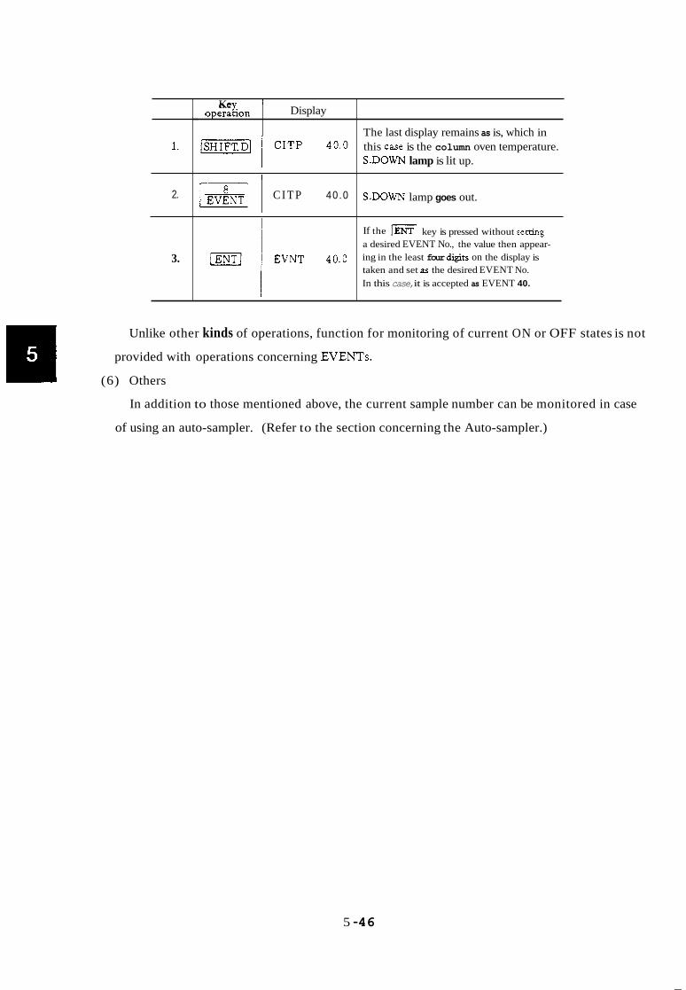
1.
2.
3.
I Display Ke
operagon
1 C I T P 40.0
The last display remains as is, which in this caSe is the column oven temperature. S-DOWN lamp is lit up.
S.DOWN lamp goes out.
If the a desired EVENT No., the value then appear- ing in the least four +U on the display is taken and set ar the desired EVENT No. In this case, it is accepted as EVENT 40.
key is pressed without setting
Unlike other kinds of operations, function for monitoring of current ON or OFF states is not
provided with operations concerning EVENTS.
(6) Others
In addition to those mentioned above, the current sample number can be monitored in case
of using an auto-sampler. (Refer to the section concerning the Auto-sampler.)
5 -46

5. Time Program
Contents
5.1 Outline
5.2 Items available for inclusion in a time program
5.3 Editing the time program
5.4 How to look up the time program
5.5 Changing the time program
5.6 If a time program is too big to be stored in memory
5.7 Starting and ending the time program
5.1 Outline
A time program consists of a set of programmed parameters to be changed at such and such
times elapsed after the program start. A variety of time programs can be edited for each of the
files used for the unit.
5.2 Items available for programming
(a) RANGE, POL, CURR
Sensitivity, polarity of a detector, and elecmcal current allowed to flow therethrough can
be changed as desired.
Ex. “DIRG 2” sets sensitivity to l o 2
(b) EVENT 91, EVENT 92
Those two relays are available for ON/OFF control of external devices as desired.
“EVNT-91” : EVENT 91 OFF
(c) Other EVENTS available as options
Eight different triac outputs are available by adding optional PC boards (PRG boards).
“EVNT 1” : EVENT 1 ON
(d) RETN.
This allows repetitive execution of a program as desired.
Further, after the program has been executed for the desired number of times, the file
number is changed for further execution.
For example, if set to “RETN 102”, first execution is repeated 10 times with the current
file number and then select file number 2 for execution of the program therein.
5 -47

INJ
Allows changes in temperature of the injection port.
AUX2
Allows changes in temperature of the temperature controlled zone AUX.2.
STRK
Allows changes in syringe stroke of the AOC.
“STRK 60” 60% of the full stroke
REPT.
Changes the number of times of repeat sample injection to be performed by the AOC.
“REPT 5” Repetition for 5 times
DET
This done has no meaning.
Used for designating a particular one of the detectors prior to setting for RANGE, POL
and/or CURR.
Ex. [=I m\ 1-1 121 [m] (j) STOP
Execution of the program can be suspended by using this key.
5.3 Editing the time program (Time can be set in minutes down to the hundredths place.)
Display
CITP 100
TIME ?
1
10
FUNC VL ?
1
The last display remains as is, which in this case is the column oven temperature.
DIALOG lamp is lit up, with inquiry made first asking for the t h e when the step is to be executed.
s.DowN lamp is lit up.
lamp goes out.
Has been set at 10 min after START.
Inquires as to which function should be manipulated at that time.
5 -48

9
1 0
1 1
1 2
1 3
1 4
1 5
1 6
1 7
1 8
1 9
2 0
2 1
2 2
2 3
2 4
2 5
2 6
2 7
2 8
2 9
3 0
3 1
3 2
3 3
3 4
3 5
3 6
3 7
3 8
TIME ?
1
15
FUNC VL ?
-
-1
TIME ?
1
15
FUNC VL ?
1
TIME ?
FUNC VL ?
TIME 10.0
FUNC VL ?
5
50
TIME ?
~ ~~ ~~
EVENT 1 is to be set to the ON state. Prompts for the time when the next step is to be executed.
Has been set at 15 min after START.
Set EVENT 1 to the OFF state at 15 minutes after START. Prompts for the time when the next step is to be executed.
Two or more actions may be performed in the same step, ie., at the same time.
Range is to be set to RANGE 1.
The actual execution may come slightly earlier or later.
RANGE 2 is to be set.
Though the time of the next step is the same as one that has been previously set, you may proceed on editing the program under this condition.
This time program is repeated five times (5 STARTS executing the heating program as well five times, of course), then returns to file 0. S.DOWN lamp is lit up.
Both S.DOWN lamp and DIALOG lamp go out, and the 14B has left the DIALOG state.
5 - 4 9

5.4 How to look up the time program loaded First, call the file into which the time program in question is loaded. ( h i FILE (3/ /ENT/ )
Be careful of the fact that if the file is changed while temperature control is going on, all the
temperatures under control shift from the temperatures set in the file then in use to those set in
the new file to which the transfer has been made.
1
2
3
4
5
6
7
8
9
1 0
1 1
1 2
1 3
1 4
Display
INJT 200
TIME 5.00
DIRG 2
TIME 10.00
EVNTl
TIME 15.00
EVNT - 1
TIME 15.00
DIRG 1
TIME 30.00
REPT 50
TIME ?
The last display remains as is, which in this case is the injection port temperature. SHIFT.D lamp is
rime of the first program step is displayed.
Parameter related to that time.
Proceed in the same manner thereafter.
Lit up.
Indicates that the end of the time program has been reached. If any addition is required, just go ahead and input further. Any desired value can be entered for the time, the program loaded is sorted auto- matically by the GC.
s.DowN lamp is lit up.
S.DOWN lamp and DIALOG lamp are extinguished.
5.5 Changes to the time program
If it is required to change part of the time program loaded, input while the display reads either
“TIME ?” or “TIME XX” (XX represents any given values), if only for the addition of new
parameters.
To delete part of the time program, proceed as follows.
5 - 50

Display
CITP 100
TIME 5.00
DIRG 2
TIME 15-00
TIME 30.00
Previous display remains as is. SHIFT.D lamp lights.
DIALOG lamp lights.
Depress the El key repeatedly to step through the program.
When the time of the step to be deleted is displayed ...
Press SHIFT.D followed by ... DEL. The step will then be deleted and the time of the next step (if any) will be displayed.
If no further deletions are required, press SJ3IFT.D (the SHIFT.D lamp lights) ... and ESCP to terminate the dialog. (The DIALOG lamp and SHIFT.D lamp are extinguished.)
5.6 Time program memory requirements
If when programming the time for a step when the prompt “TIME ?” appears, and “TIME
O.OO” is displayed upon input of some value, then there is insufficient memory available.
Secure additional memory by deleting unwanted files.
5.7 Time program START and STOP
As in the case of the heating program, a time program is started up by pressing the START
button. (Refer to the section on Heating Program.)
If execution of the time program is to be stopped midway, press the key. You cannot
continue execution of the heating program with only the execution of the time program being
suspended.
5 - 5 1

6. Files
Contents
6.1 Outline
6.2 Setting
6.3 How t o look up the number of the file then in use
6.4 Copying the contents of a file
6.5 Deletion of the contents in a file
6.6 If there is no more space for expanding a file
6.1 Outline
It is possible to generate up to 10 files for this unit. And it is possible to save time programs,
GC parameters, heating programs and AOC parameters in each of these files. It is to be noted,
however, that, as for the AOC parameters, except for the four items (IJlT, IJ2T, STRK and REPT)
they are used commonly for all the files.
Each of the fdes is made to have a variable length, that is, area of a file can only be secured in
the memory by setting the file. Accordingly, a number of files can be generated if each of them
is small in size (up to 10 fdes), but not so many files can be generated if each of them is large in
size.
“File 0,’ is open at the time of turning on the power switch (e.g. when no setting has been made
for file yet), therefore, all the programs loaded without selecting a file are saved in “File 0”.
6.2 Calling a file
Prior to the editing of time program, GC parameters and heating program, the following key-in
operations are to be made to set a file into which they are to be loaded. (If no setting is made,
File 0 is set.)
5 - 52

Ex. When calling File 4:
~ 1 operanon Key. , Display
2.
6.3 How to look up the file No. then in use
m 4
1 operagon Ke Display
CITP 100 The last display remains as is, which in this caSe is the colum oven temperature.
6.4 Copying the contents of a file
The contents of file then in use can be copied into another file as they are. If copying is to be
made into a file that has already been opened, it is recommended that deletion of the file should
be made first to clear it (referring to Para. 6-5) before copying to it.
2. I w] FILE 4 1 Number of the file then in use is displayed, which i in this case is FILE 4.
1.
5 - 53
Key: Display I operanon
-1 INJT 200 The last display remains as is.
3.
S.DOWN h n p is Lit up.
S.DOWN lamp goes out.
3
COPY 3 Contents of the current file used have been copied into FILE 3.
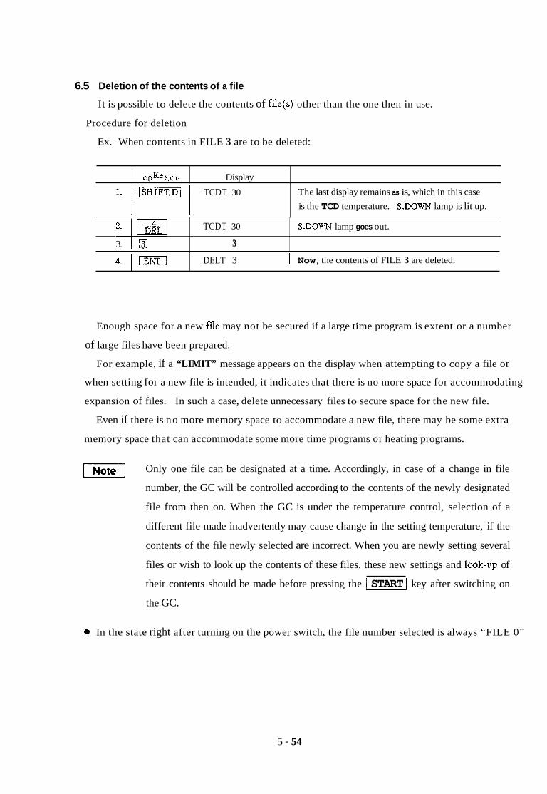
6.5 Deletion of the contents of a file
It is possible to delete the contents of file(s) other than the one then in use.
Procedure for deletion
Ex. When contents in FILE 3 are to be deleted:
operaaon Key. Display
1. 1 [-I 1 TCDT 30 The last display remains as is, which in this case is the TCD temperature. S.DOwN lamp is lit up.
3. 0
Enough space for a new fde may not be secured if a large time program is extent or a number
of large files have been prepared.
For example, if a “LIMIT” message appears on the display when attempting to copy a file or
when setting for a new file is intended, it indicates that there is no more space for accommodating
expansion of files. In such a case, delete unnecessary files to secure space for the new file.
Even if there is no more memory space to accommodate a new file, there may be some extra
memory space that can accommodate some more time programs or heating programs.
TCDT 30 S.DOWN lamp goes out.
3
-1 Only one file can be designated at a time. Accordingly, in case of a change in file
number, the GC will be controlled according to the contents of the newly designated
file from then on. When the GC is under the temperature control, selection of a
different file made inadvertently may cause change in the setting temperature, if the
contents of the file newly selected are incorrect. When you are newly setting several
files or wish to look up the contents of these files, these new settings and look-up of
4. 1 IENTJ
their contents should be made before pressing the I START 1 key after switching on
the GC.
DELT 3 1 Now, the contents of FILE 3 are deleted.
0 In the state right after turning on the power switch, the file number selected is always “FILE 0”
5 - 54

7. Other Operations
operaQon Key
I. 1
Contents
Display
The last display remains as is, which in this case INJT 200
7.1 Self-diagnosis function
7.2 Listing
7.3 Connection with an external data processing unit
is the injection port temperature. S.DOWN lamp is lit up.
2. 1 INJT 200 I
S.DOWN lamp goes out.
4. j 5. ' [ENT]
7.2 Listing
(1) Listing
~
13
CITP. x x
~ Self-diagnosis is provided as AUX function 13.
Display appears in the format shown on the left if
It is possible to list on an external unit (Chromatopac, etc.) the AOC parameters, heating
program, time program and GC parameters of the file designated.
(2) Operation for listing
The number assigned for the device selected for output of the list is set according to the
instructions in Para. 7.3 on Link Device. Also the file number selected for listing is set accord-
I I I I
~
5 - 55
no abnormality is found. If there is any sign of abnormality noted, the address of the faulty part is displayed.

Display Ke ope ragon
1. 1 mJ CITP 100 The last display remains as is.
I I
6. -1
LIST. P
LIST. P While listing is going on, the DIALOG lamp remains on. Upon completion of listing, the DIALOG lamp goes out to show escape from the DIALOG mode.
DIALOG lamp is lit up, indicating the DIALOG
mode.
operatlon Key.
5. I D l I 1 1 Key in 66179 when listing is desired.
Display
1. [SHIFT.Di
2.
3-
CITP 100
MI CITP 100 I
~ Listing of AOC parameters is available as AUX function 3. El 3
The last display remains as is.
S.DOWN lamp is lit up.
5-
6. a 1 Key in “1” when listing of parameters is desired.
Listing of parameters s t a r t s . Upon completion of
hting, DIALOG lamp goes out.
LIST. A
I I I I
4 . 1 1 LIST. A 1 DIALOG lamp is lit up.
1.
operatlon Key. Display
-1 CITP 100 The last display remains as is.
S.DOWN lamp is lit up.
2.3 Listing GC parameters
2.
3.
4.
I I ’ CITP 100 S.DOWN lamp goes out.
I-& pm-1 LIST GI DIALOG lamp is lit up.
4 Listing of GC parameters is available as AUX function 4.
5.
6.
g j 1 Key in “1” when listing of parameters is desired.
1 LIST GI Listing of parameters starts. Upon completion of
1 listing, DIALOG lamp goes out.
5 - 56

2.4 Listing of heating program
operanon Key. Display
1. 1 JSHIFT.D/ I CITP 100
~ ~ ~~~
2.
3.
4.
1 The last display remains as is.
mi CITP 100 S.DOWN lamp goes out.
1
g 15 Listing of heating program is available as AUX function 15.
I 1 S.DOWN lamp is lit up.
5. /m 6.
7. [ENTI
DIALOG lamp is lit up.
Key in “1” when listing of parameters is desired.
Listing of parameters s t a r t s . Upon completion of
listing, DIALOG lamp goes out.
LIST GP
1
LIST GP
(3) When no listing of parameters is required:
When no listing of parameters is required, key in “0” instead of “1”. Then, no luting is
performed and DIALOG lamp goes out, allowing escape from the DIALOG mode. You can
also escape from the DIALOG mode by pressing the -1 and keys.
(4) Error display
If either of the following error messages appears on the display when you attempt to list,
it indicates failure to perform some necessary setting. If either error message is given, the
unit leaves the DIALOG mode.
“SET LDVC”
This error message appears when the listing device (printer, CRT, etc.) has not been desig-
nated. In such a case, set the appropriate h k device code. (Refer to 7.3 Link Device.)
“NOT LINK”
This display appears when no link has been established between the GC and the external
output device. In this case, make necessary steps needed for establishing a proper linkage with
the output device (e.g., “OPEN TRS l”, etc., a t the Chromatopac). See next.
5 - 57

7.3 Connection with an external data processing unit
By adding a proper current loop interface, the unit can be operated in combination with
a Chromatopac. By making use of the BASIC capability of the Chromatopac, the GC functions
can be enhanced substantdy.
For details on the operating procedures for the Chromatopac, refer to chapter 10; “Other Curren
Loops”, or the instruction manual for the Chromatopac.
1. Setting of the link device code
(1) Link device
When the contents of time program, AOC parameters, GC parameters, etc. used for the
unit are to be output to an external device, setting should be made beforehand for the code
number of the selected external output device. External output device numbers avdable
for setting are between 0 and 55, and the default value is 0.
(2) Setting procedure
operatlon Key. Display
1. The last display remains as is.
S.DOWN lamp is lit up.
(-1 CITP 100
I I 1
3. I El
2. 1 mi 1 CITP 100 S.DOWN lamp goes out.
8 1 Settine for link device is a d a b l e as AUX function 8.
4.
5.
6.
7.
“TI LDVC 0 The link device then set is displayed.
DIALOG lamp is lit up entering the DIALOG mode.
m 1 Link device 11 is set.
m 11 1 [ENTI STRK 10 11 is set for link device and display advances to
~ the next item in the parameter list. I
~
8.
9.
5 - 58
[SHIFT.?j] STRK 10 When setting is complete, operation must be made
to escape from the DIALOG mode.
S.DOWN h n p is fit up.
[EsCPI STRK 10 DIALOG lamp goes out.
S.DOWN lamp goes out.
Now, the GC has escaped from the DIALOG mode.

(3) In case of erroneous setting
In case of an erroneous setting, if you haven’t pressed the lml key yet, delete the
display by pressing the
the /ENTI key already, call up the LDVC display once again by pressing the [m] key by
the required number of times, or escape temporarily from the DIALOG mode by effecting
steps )8j and , and start again from step . What you have to bear in mind in this regard is the need for escaping from DIALOG mode
key, and then enter the right number. If you have pressed
temporanly upon completion of necessary setting. Otherwise, you cannot make any other
key-in operations.
(4) To look up the set value:
1.
operatlon Key Display
1-1 CITP 100 The last display remains as is.
I ~ S.DOWN lamp is lit up.
2.
3.
I 1 I
CITP 100 S.DOWN lamp goes out.
@I 8
4. ~ 1 LDVC 11 The link device currently set is displayed.
DIALOG lamp is lit up.
S.DOWN lamp is lit up.
Take necessary steps for escaping from DIALOG mode.
.%DOWN lamp goes out.
DIALOG lamp goes out.
Now, has escaped from DIALOG mode.
(5) Meaning of LDVC
LDVC stands for Link Device Code, used to specify the selected output device, e.g. either
the CRT of the external device (Chromatopac) or a plotter, etc. Setting is done with two
digits; the MSD is for setting the particular channel of the Chromatopac to which signals
from the detector are connected. (“3” is set if connected with both channels 1 and 2.)
The LSD is used for designating either CRT or the plotter of the Chromatopac. Designate 2
if listing is desired on the CRT, or set 1 if listing is desired via the plotter.
LDVC 22 means that signals from the detector are connected with channel 2 and listing
is to be made on the CRT.
5 - 59

Appendix 1. Error Display
The following error displays appear in case of an erroneous operation by‘the user, or due to an
abnormal occurrence in the unit, or other causes.
“OVER COL”
This error message appears on the display if column oven temperature exceeds the set maximum
column oven temperature, and the buzzer keeps on sounding. At the same time, temperature
control for the column oven stops.
If the setting of the maximum temperature is too low, while the column oven temperature is the
right temperature as has been set, raise the maximum temperature setpoint. If column oven temper-
ature is abnormally higher than the setpoint, which suggests a failure, turn off the power switch and
investigate.
To escape from this abnormal condition, press the key after the column oven temperature
has fallen sufficiently lower than the set maximum value. Then, the buzzer stops sounding and
temperature control operation is resumed.
“OVER INJ”
If temperature of the injection port exceeds 45OoC, or the temperature of the detector exceeds
the set maximum value, this error message appears and the buzzer keeps on sounding. Since such
a high temperature cannot be set for the injection port, this is a symptom of failure.
Care should be given also to the fact that the same error message appears if the temperature of the
detector should exceed the set maximum temperature. If this error message is given, all temperature
control is suspended.
“OVER AUX”
This error message appears if the temperature of AUX.l exceeds the set maximum temperature,
and the buzzer keeps on sounding.
“ERROR CM”
This error message appears if there was a change to the contents of the fdes while the power
supply was off due to battery discharge or lightning, etc. The file contents are now presumed to be
corrupt.
“ERROR CRY’
This error message appears in case of trouble in information exchanged between the gas chromato-
graph and the Chromatopac. In such a case, switch off both the gas chromatograph and the
Chromatopac temporarily and establish the link between them correctly.
5 - 60

“ERROR 1”
Error in data transmitted or received.
“ERROR 2”
This message tells that either no gas is flowing in flow rate measurement, or the flow rate is
extremely low disabling measurement. (Option)
“ERROR 3”
General error display. This error message appears if there is no such function as has been selected.
“ERROR 4”
General error display. This error message appears if the value input is unacceptable.
c‘ NON”
This indicates that the particular one of the detectors with the number selected is not connected,
in monitoring detectors.
“NON ”
This indicates that, in setting for a detector, there exists no such detector as selected when
entering a number other than 1 to 4.
“CITP.XX”, “INJT.XX”, “PROG.XX”
These pseudo-error messages appear, when monitoring current temperature or current program
number, etc., if temperature control operation has not yet been started. As the temperature control
operation starts by pressing the -1 key, the right value is displayed in place of “XX”.
“SET LDVC”
This appears, in listing of a program, etc., if no setting has been made for the link device code.
“NOT LINK”
This appears, in transferring/receiving to or from the outputlinput units (data processing unit), if
no linkage has been established with such an external unit.
Other displays c c * * > ,
Indicates that temperature control operation is started, or is now going on.
“LINK OK”
This appears when linkage is established with the external unit, with the buzzer sounding for
about two seconds.
“LIMIT~y
This appears if there is no more space available for expanding a fde, or if it is attempted to create
a heating program involving 6 or more steps.
5-61

“INITIAL”
This message appears in case of a catastrophic change occurred in the contents of memory, with
all the setting conditions being initdized. In such a case, set the conditions again from the begin-
ning.
“FAULT”
This appears if part of the system program (ROM) has been destroyed. In such a case, contact
OUT service staff, as it is impractical to use the unit with this condition.
5 - 6 2

221-40010-06
6. Construction and Maintenance

1. Construction
nl
Side view
0 m - ~ a s e u n i t
@ Terminalunit
0 5~ power supply
@ TCD power controller
@ PCB switch unit
@ Key unit
@ Power cord assembly
@ Auto-cooling unit
Rear view
P/N 221-44388-91 P/N 22 1-44403-92 (1 15V ~ O W H Supply)
221 -44403-93 (22OV, 230V. 240V. ~ O W I Supply)
P/N 074-80642-15
P/N 221 -328%-%
P/N 221-4193-91
P/N 221-31772-%
P/N 221-43318-93
P/N 221-32068-91
6 - 1

---I - - I--
Detector conmller(FPD)
I---
i RS232C or Curnnt loop or optical link i
c1 .- E 3 A s
8 P B 0
a 0 \o
Detector contmll@TD)
I n I
I I I I I
I I
U
- 11""
1 cRG
1
- } STARTOUT -
} STARTlN I I
l k
Power switch unit
Block Dia

Heating units
sensor
mrcontroller
V
I i n
4 j l TCD oontrol unit
switch unit
fJ
agm of Electrical systems
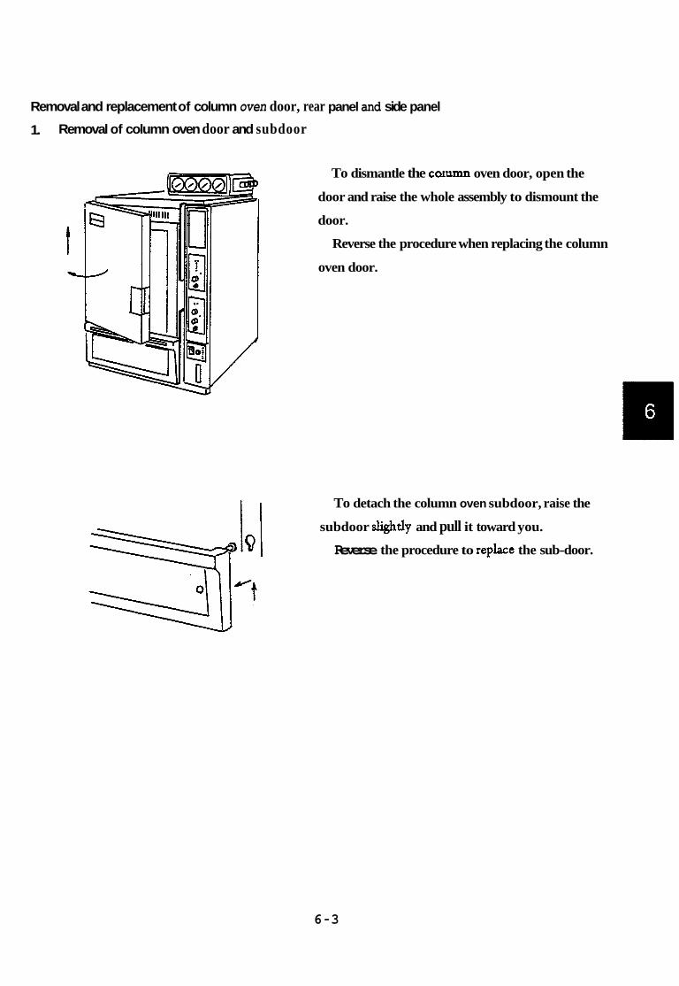
Removal and replacement of column oven door, rear panel and side panel
1. Removal of column oven door and subdoor
To dismantle the cc,ann oven door, open the
door and raise the whole assembly to dismount the
door.
Reverse the procedure when replacing the column
oven door.
To detach the column oven subdoor, raise the
subdoor slightly and pull it toward you.
Reverse the procedure to replace the sub-door.
6 -3

-1 Highvoltage
You may get an electric shock. Only the authorized service engineer is allowed
to detach the rear panel and right side panel.
2. Removal of rear panel
To detach the rear panel, first disconnect wiring
for the detector control unit and for the optional
boards.
By removing the 11 screws shown in the drawbg,
the rear panel can be detached easily.
Reverse the procedure to replace the rear panel.
To ensure safety, be sure to disconnect the power
cord for GC-14B from the outlet without a.
3. Removal of right side panel
To detach the right side panel, remove the four
screws on the side and three screws on the rear face
as shown in the figure. Then the panel can be
removed easily. Be careful as catches protruded
from the top panel.
Reverse the procedure to replace the side panel.
6 - 4

Construction of basic components and spare parts required are as follows.
Construction
Column oven
INJ unit, single/dual
DET oven
Spare parts @ Column oven heater assembly (1.3kW)
Part No. for 115V power supply 221-28919-92
for 220V - 24OV power supply 221 -28919-93
Tu-"-q Heater insulator 221-28919-05
Sleeveinsulator 221-32897
@ Ptsensor 221-41059-92
@ Thennocouple 221-32977-92
@ Single INJ heater (80W)
for 1 15V power supply 221-32877-01
for 220V - 240V power supply 221 -32877-03
@ Dual INJ heater (150W)
for 1 15V power supply 221-29281-01
for 220V - 240V power supply 221-29281-03
22 1-44685-9 1
@ Thermocouple 221-32977-92
0 Heater wiring cord 221-32964-91
@ Pt sensor
(1 15V, 220V, 24OV)
(230V) -38
0' Heater wiring cord used for temperature Control with AUX2 oven 221-32964-93
(1 15v. 220v. 240V) -30
(230V)
@ DET heater assembly (200W)
for 1 15V power supply 221-32980-91
for 220V - 240V power supply 221-32980-93
0 Pt sensor 22 1-44685-92
0 Thermocouple 221-32977-92
6 -5

Electrical system and related parts (Refer to the Block Diagram of Electrical Systems)
Construction Terminal unit and peripheral parts
Switch unit
Base unit
Smre D ~ S
See fuses information page 6-7
Door switch Power switch
Lamp switch
Lithium battery
Service life 5 years
22 1-2978 1-9 1 064-14021 064-54604-06
074-73307-01
6 -6

Fuses information
Terminal unit fuses
Fuse designation Line Voltage Fuse rating and type Part Number
F1, F2 115V AC250V 15A UL STD 198G 072-01665-36 ceramic body
ceramic body
ceramic body
glass body
glass body
F1, F2 22OV/23OV/24OV AC250V 8A UL STD 198G 072-01665-33
F3, F4 115V AC25OV 1OA UL STD 198G 072-01665-34
F3, F4 22OV/23OV/24OV AC250V 5A UL STD 198G 072-01 66423
F5, F6 115V AC250V 5A UL STD 198G 072-01 66433
F5, F6 22OV/23OV/24OV AC250V 3A UL STD 198G 072-01 66430
6 - 7

3. Troubleshooting and Remedy
To ensure safety, be sure to disconnect the power plug of the GC-14B from the outlet before
checking electrical part(s) inside the unit main body.
Troubleshooting procedures for failure occurring in the unit main body and countermeasures taken
Phenomenon
1. Does not work at all.
2. Heater switch cannot be turned on.
3. Temperature of each part does not rise.
4. Temperature in column oven does not rise. (Requirement in item 3 above is met.)
5 . Temperature in AUX.2 does not rise. (Requirement in item 3 is met.)
~
6. Temperature at each part does not stabilize.
7. There is a certain difference between the setting point and measurement value.
Cause ~~
a. AClOOV is not supplied. b. Fuse burnt out. c. Faulty power switch.
a. Faulty heater switch.
a. Break in heater.
b. Break in heat-sensitive element.
c. Overheat protector is activated due to overheat in thermo- couple.
d.
e. Faulty relay used in power
f. Faulty temperature control supply unit.
circuit. ~~ ~ ~~
a. Faulty door switch.
a. AUX.2 oven short pin is open on terminal unit.
a. Faulty heat-sensitive element.
b. Faulty triac. c. Faulty temperature control
circuit.
a. Faulty heat-sensitive element.
b. Faulty base unit.
Check and countermeasure taken
a. Check with tester. b. Check with tester. c. Check with tester.
a. Check with tester.
a. Disconnect connector and check with tester.
b. OVER (abnormal temperature) message appears and buzzer sounds. Disconnect terminals and check with tester.
c. Check performance of protector with LED on terminal unit.
d. Check output from triac with tester or on oscilloscope.
e. Check with tester.
f. Repair or replace.
a. Check with tester.
a. Check with tester.
a. Disconnect terminals and check with tester.
b. Check on oscilloscope. c. Repair or replace.
a. Disconnect terminals and check with tester.
b. Adjust, repair or replace.
6 - 8

Phenomenon
8. Unable to perform key inputs. Abnormal characters appear on display.
Resistance of the heat-sensitive element in normal conditions is 100 + 0.4 X temperature of the
heat-sensitive element ("C)Q.
Cause Check and countermeasure taken
a. Check to see if connector is posi- tioned correctly. If not, set it correctly.
a. Faulty contact between key unit and main body.
b. Faulty switch unit. c. Faulty 5V power supply. d. Faulty base unit.
b. Set connector correctly. c. Check with tester. d. Repair or replace.
6 - 9

4. Maintenance
Periodic maintenance and inspection of the GC-14B will ensure good analysis results. The items cov-
ered in this chapter are listed below.
1. Overtemperature protection system
2. Cleaning of cover
3. Glass insert
4. Septum
5. Graphite ferrule
6. Capillary column
7. Hydrogen flame ionization detector (RD)
4.1 Overtemperature protection system
Check the overtemperature protection system every six months.
0 Checking procedure
(1) Disconnect the column.
(2)
(3)
(4)
(5)
Set the maximum temperature of COL to 90°C. (FUNCTION 7)
Set the column oven temperature to 100°C.
C o n f m that the overtemperature protection system operates properly, and the temperature falls.
Check the temperature control zones respectively in the same way.
4.2 Cleaning of cover
Cleaning of cover should be done with a soft cloth slightly damped with water or a solution of
water and a mild detergent. Carry out appropriate decontamination if hazardous material is spilt on or
inside the equipment on user’s responsibility. Before using any cleaning or decontamination method
except those recommended by the manufacturer, user should check with the manufacturer that the pro-
posed method will not damage the equipment.
4.3 Maintenance of glass insert
I CAUTION 1 HIGH TEMPERATURE
Maintenance of the injection port should be performed only once the temperature has been low-
ered. Also, turning the injection port nut when hot can cause the nut to seize.
-1 For details on handling the glass insert, refer to “Chapter 7: Splithplitless injection port”.
6 - 10
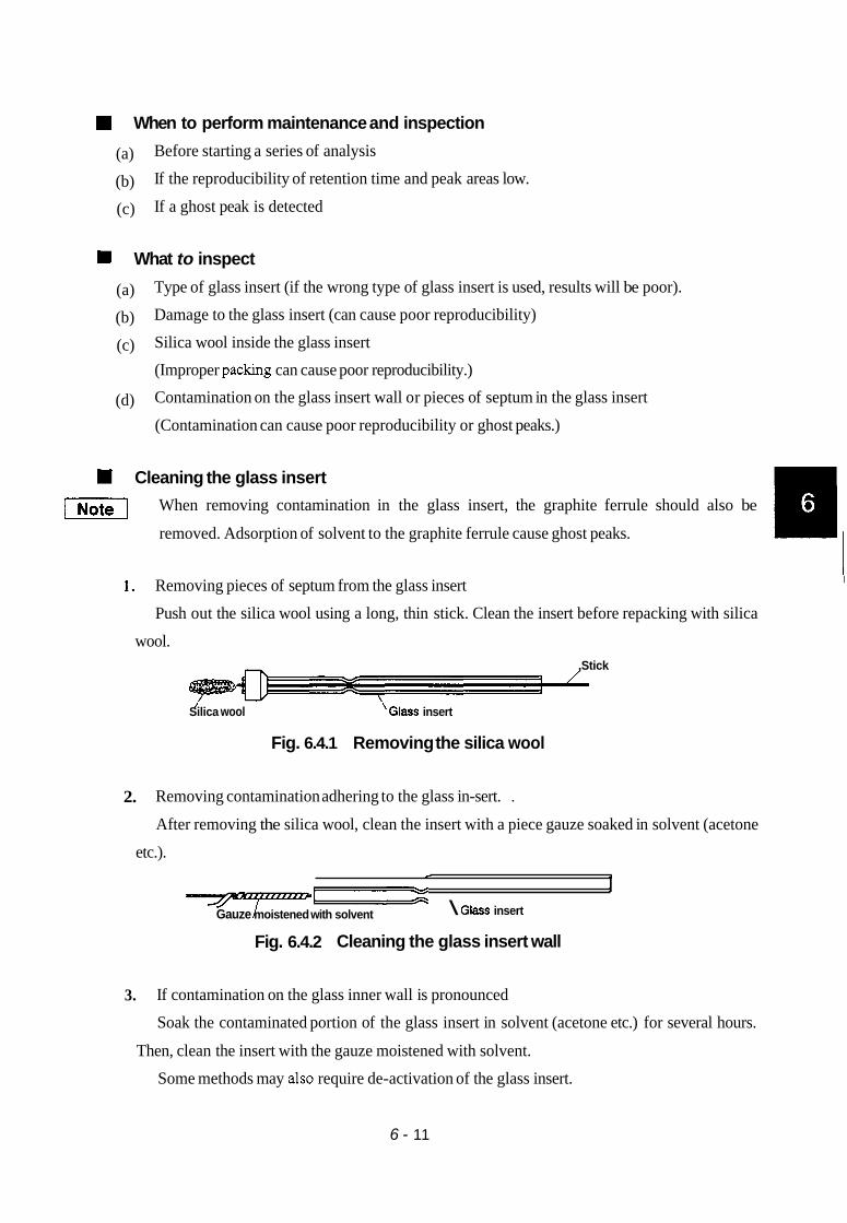
H When to perform maintenance and inspection
(a)
(b)
(c)
Before starting a series of analysis
If the reproducibility of retention time and peak areas low.
If a ghost peak is detected
What to inspect
(a)
(b)
(c)
Type of glass insert (if the wrong type of glass insert is used, results will be poor).
Damage to the glass insert (can cause poor reproducibility)
Silica wool inside the glass insert
(Improper packing can cause poor reproducibility.)
Contamination on the glass insert wall or pieces of septum in the glass insert
(Contamination can cause poor reproducibility or ghost peaks.) (d)
I Cleaning the glass insert
[=I When removing contamination in the glass insert, the graphite ferrule should also be
removed. Adsorption of solvent to the graphite ferrule cause ghost peaks.
I 1. Removing pieces of septum from the glass insert
Push out the silica wool using a long, thin stick. Clean the insert before repacking with silica
wool. ,Stick
/ Silica wool \GIXS insert
Fig. 6.4.1 Removing the silica wool
2. Removing contamination adhering to the glass in-sert. .
After removing the silica wool, clean the insert with a piece gauze soaked in solvent (acetone
etc.). e 1
T7z Gauze moistened with solvent \ Glass insert
Fig. 6.4.2 Cleaning the glass insert wall
3. If contamination on the glass inner wall is pronounced
Soak the contaminated portion of the glass insert in solvent (acetone etc.) for several hours.
Then, clean the insert with the gauze moistened with solvent.
Some methods may also require de-activation of the glass insert.
6 - 11

Test tube -
Solvent (acetone etc.) 1
I Put the solvent of the quantity required for cleaning.
Fig. 6.4.3
4.4 Maintenance of septum
1 CAUTION 1 HIGH TEMPERATURE
Maintenance of the injection port should be performed only once the temperature has been low-
ered. Also, turning the injection port nut when hot can cause the nut to seize.
vl For details on handling the septum, refer to “Chapter 7: Splithplitless injection port”.
W When to perform maintenance and inspection
(a) Before starting a series of analysis
(b) When reproducibility of retention times and peak areas are poor.
(c) When a ghost peak is detected (d) After approximately lo0 injections.
W What to inspect 0
0
Gas leakage (This will be evidents as retention times shift.)
Contaminated septum (This will be evident as ghost or extra peaks appear.)
6 - 12
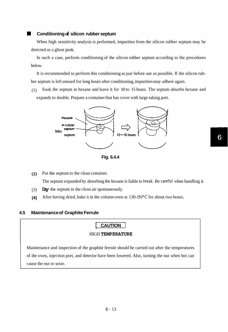
Conditioning of silicon rubber septum
When high sensitivity analysis is performed, impurities from the silicon rubber septum may be
detected as a ghost peak.
In such a case, perform conditioning of the silicon rubber septum according to the procedures
below.
It is recommended to perform this conditioning as just before use as possible. If the silicon rub-
ber septum is left unused for long hours after conditioning, impurities may adhere again.
(1) Soak the septum in hexane and leave it for 10 to 15 hours. The septum absorbs hexane and
expands to double. Prepare a container that has cover with large taking port.
Silicon rubber H e x a n e ~ septum 10-15 hours M
Fig. 6.4.4
(2) Put the septum to the clean container.
The septum expanded by absorbing the hexane is liable to ,re&. Be carefu, when handling it.
Dry the septum in the clean air spontaneously.
After having dried, bake it in the column oven at 130- 1 5OoC for about two hours.
(3)
(4)
4.5 Maintenance of Graphite Ferrule
[ CAUTION 1 HIGH TEMPERATURE
Maintenance and inspection of the graphite ferrule should be carried out after the temperatures
of the oven, injection port, and detector have been lowered. Also, turning the nut when hot can
cause the nut to seize.
6 - 13

Areas where graphite ferrules are used
Graphite ferrule (glass insert)
I
\ 1
t I
I
I /' Graphite ferrule
(capiilary column)
Capillary column
/
GraDhite ferrule (FID jet)
Fig. 6.4.5
When to perform maintenance and inspection
(a) When installing a new graphite ferrule
(b) When a ghost peat is detected in the Programmed analysis
(c) When a large baseline drift occurs during programmed analysis
What to inspect
Gasleakage
(Leakage of carrier gas caused by deterioration of the graphite will cause poor reproducibility.)
0 Impurities in the graphite
If impurities are present at the connection of the glass insert or column inlet, a ghost peak
may appear. (In the typical split analysis, column graphite ferrule contamination is much less
likely to cause ghost peaks because of the carrier gas flow path.)
If impurities are present at the connection of the column outlet or FID jet, baseline drift may
occur.
Conditioning of graphite ferrule
If impurities in the graphite ferrule cause problems, condition the graphite ferrule using any of
the following methods. Perform conditioning just prior to analysis. After extended periods of non-
use, conditioning may become necessary.
6 - 14

1. Conditioning with gas torch
Place the graphite ferrule into blue flame of gas torch for approx. 30 seconds.
Use tweezers or a wire to hold the ferrule in the flame. I Graphite ferrule ,
Fig. 6.4.6
2. Conditioning in the column oven
Place the graphite ferrule in the column oven and condition at 399°C for 2 - 3 hours.
4.6 Maintenance of Capillary Column
HIGH TEMPERATURE
Maintenance and inspection of the graphite ferrule should be carried out after the temperatures
of the oven, injection port, and detector have been lowered. Also, turning the nut when hot can
cause the nut to seize.
vl For details of handling of the capillary column, consult the column instruction manual.
W When to perform maintenance and inspection
(a) When using a new graphite ferrule or a graphite fermle that has not been used for an extend-
ed period
(b) If ghost peaks are is detected
6 - 15
(c) If the baseline is unstable
What to inspect
(a) Baseline (If impurities have adhered to the liquid phase of the capillary column, the baseline
becomes unstable or a ghost peak may be detected.)
(b) Visual inspection of capillary column
Conditioning the capillary column
1. Changing the carrier gas flow rate
When conditioning the column, it is not necessary to modify the flow rate of the carrier gas
from that which is required for analysis. However, carrier gas can be conserved by decreasing
the split ratio.
2. Setting the column oven temperature
Set the temperature of the column oven approximately 3OoC higher than that is required for
analysis. However, do not exceed the maximum allowable temperature of the column.
3. Setting temperature of the injection port and the detector
It is not necessary to change the temperature of the injection port. Set the temperature of the
detector approximately. 3OoC higher than that of the column oven.
4. Conditioning time
Perform conditioning for two or three hours, depending on the degree of contamination.
1x1 Some types of column liquid phase are easily damaged. Take note of the maximum temper-
ature of the column and conditioning time. In addition, if the presence of oxygen in the car-
rier gas can seriously damage the liquid phase.
6 - 16

4.7 Maintenance of FID
[ CAUTION I HIGH TEMPERATURE, HIGHLY FLAMMABLE, SHOCK HAZARD
Before performing maintenance and inspection of the HD, be sure to frrst perform as follows.
1.
2.
3.
4.
Cur off the hydrogen gas supply to extinguish the flame.
Lower the detector temperature to below 100°C.
Turn OFF the power to the instrument.
Remove the capillary column from the FID.
If maintenance is performed when the FID is hot, a burning hazard exits. Damage to the detec-
tor may occur when disassembly is performed when hot. The threaded set screws and nuts may
potentially seize.
vl For details on handling the FID, refer to Chapter 12 “Hydrogen flame ionization detector”.
When to perform maintenance and inspection
Perform inspection and maintenance in the situations listed below.
(a) FID cannot be ignited.
(b) No peaks are detected
(c) Noise is severe.
(d) Peak shape is abnormal.
Points of inspection
0
0
Clogged jet. (Clogging of the jet may cause ignition failure or no detection of peaks.)
Contaminated jet. (Contamination may cause noise.)
Damaged jet. (Damage can cause abnormal peak shape.)
Cleaning the FID jet
If thip of the FID jet is clogged, remove the FID jet reffering chapter12 and insert a thin stick
into the jet tip to clean it.
6 - 17

22 1-4001 0-07A
7. SPL-14 SpIit/SpIitless Sample Injector
In this chapter, explanation is given on how samples are introduced for the capillary system.
The model GC-14BSC is equipped with this SPL-14 split/splitless sample injector as standard.
SPL-14 Injection unit Flow controller \ -I--- -
SPL- 14 low controller

1. Split/Splitless Sample Injection
The capillary sample injection part of the unit is adaptable to either split or splitless type sample
injection. In order to avoid ghost peaks that may result from impurities eluted from the rubber
septum, which presents problems in trace analyses, the sample injection port is provided with a flow-
line for purging the rubber septum, which is called the “septum purge flowline”.
Solenoid valve SVl is provided before the split flow control resistance (needle valve) to allow ON-
OFF of the gas flow.
Also, a filter is provided for each of these flowlines to protect these parts against attack by organic
substances.
Explained briefly are the principles of the split and splitless sample injection methods.
Sample evaporation chamber
Carrier gas
Make-up gas
Hydrogen
a High-voltage electrode
Fig. 7.1 Split/splitless sample injection method
7 - 1

1.1 Split sample injection method
(1) Three different kinds of gases can be used as carrier gas; of these helium gas is generally
used as the carrier gas for its high resolving power and less time needed for analysis. Control of
carrier gas flow rate is usually done in constant flow rate control with a packed column or
wide-bore capillary column. With capillary columns, a constant-pressure control method is
usually employed, because the flow rate of fluid flowing in the capillary column can be main-
tained constant when adjusting the split ratio, as to be explained below.
(2) The inlet side of the capillary column is inserted into the glass insert in the injection port,
and carrier gas supplied is divided into two separate flowlines; the capillary column and the
splitter, respectively. Assuming that the flow rates of carrier gas flowing in these two
separate flowlines to be v1 andv, [mP/min], then the split ratio can be expressed as
v1:v1 +v2.
( 3 ) Split ratio is selected usually in the range between 1/20 and 1/200. The reason for providing
a splitter is that the absolute quantity of sample needs to be kept low to obtain the high separa-
tion performance that can be attained with the capdary column. Accordingly, when the split
ratio is set at 1/50, 1/50 of the quantity of sample injected is introduced into the capillary colum
and the remaining sample is discharged to the outside by way of the splitter. (Although accurate
control may be necessary if concentration of the sample is extremely low or high, split ratio is
normally set at around 1/50 or at 1/100.)
(4) To obtain separation on the capillary column in high efficiency, selection of proper flow rate
of the carrier gas is essential. When helium is used as the carrier gas, around 40cm/sec is
appropriate, for example, in terms of the linear velocity. The optimum flow rate of carrier gas
is obtained on the H-U curve as to be explained later with reference to Fig. 7.2. Flow rate
inside the capillary column is adjusted with the column inlet pressure. Two methods are avail-
able for measurement of flow rate; (1) direct measurement at the column outlet using a soap
film flow meter, and (2) with the column connected with the detector, methane gas is injected
and the carrier gas flow rate (linear velocity) is calculated from the retention time measured.
(5) The outlet side of the capillary column is connected with the detector, and a gas called
make-up gas is fed to the connection part, at a rate of 40 to 60mPlmin in normal cases.
The reasons for adding such a make-up gas are; (1) to obtain carrier gas flow rate necessary for
maintaining the sensitivity of the detector (because of the low flow rate in the capillary column)
and (2) to increase the gas flow rate for preventing expansion of peaks at the junction of the
detection and the column.
7 - 2

( 6 ) In the case of split sample injection, once the flow rate in the capiuary column, split flow
rate and the make-up gas flow rate have been decided, subsequent operations are carried out
just in the same manner as those for ordinary analysis using packed columns. This method is
most commonly used for analysis where concentrations of samples are relatively high.
When concentration of sample is low, however, splitless sample injection, as to be described
next, becomes necessary.
HETP
- I I I I
10 20 30 40 cm/ sec
Linear velocity of carrier gas
Fig. 7.2 Influence by the kinds of carrier gas (H-U curves)
1.2 Splitless sample injection method
This sample injection method is used when concentration of sample is low (at 10ppm or lower,
for example), which cannot be detected accurately by the split sample injection method.
This method (called the Grob method) can be used interchangeably with the split sample injection
method. Samples applicable to this method are limited to samples that have been diluted with
solvents.
.
To avoid ghost peaks (peaks resulting from impurities), a rubber septum purging flowline is
provided. Solenoid valve SVl is provided before the split resistor (needle valve) to allow ON-OFF of gas
flow.
7 - 3

(1) Solenoid valve SV1 is installed in the split gas flowline, which closes immediately before
sample injection.
Since the carrier gas flow rate is controlled by the pressure regulator, the pressure at the inlet
part of the capillary column is maintained constant even when the solenoid valve opens or
closes. As a result, flow rate of carrier gas fed through the capillary column is always main-
tained at a constant rate.
Flow rate of carrier gas allowed to flow in the injection port is low, measuring
at around 1 to 2mQ/min, when the solenoid valve is closed, but it is increased to 50 to 100mQ/
min (when the split ratio has been set at around 50).
(2) Sample injected into the glass insert with solenoid valve SV1 closed is fed to the capillary
column vaporized. Since the inner volume of the injection port is approximately
0.4mQ, most of the sample is to enter the capillary column in 0.5 to 1 minute, if carrier gas is
allowed to flow at a rate of 1 to 2mQ/min.
If analysis is conducted under this condition, however, heavy tailing may occur due to the
solvent that has diffused and is staying within the injection port. To avoid this, solenoid
valve SV1 is opened later to increase the flow rate of carrier gas flowing in the port,
so as to expel such residues to the outside of the system through the split discharge
outlet. Thus, trouble due to the tailing of the solvent peaks can be minimized with the
Grob method.
(3) Initid temperature of the capillary column is kept low for the stage where sample is fed
from the injection port to the capillary column. It is generally considered that the
appropriate temperature for the stage will be the temperature lower by 10 to 40°C than the
boiling point of the sample solvent. The reason for this is that, if the temperature is kept with
this range, the solvent evaporated within the injection port will condense immediately
after entering the capillary column to form a liquid film on the inner surface of the
capillary, which in turn will act as a sort of fixed phase, so that even the components of
relatively low boiling points can be trapped in the narrow zone to suppress expansion of peaks.
(Needless to say that this effect cannot work with those components with boiling points lower
than that of the solvent, which cannot be trapped.) Such an effect is called the “solvent
effect”, and is differentiated from the trapping attained by cooling in normal cases. Therefore,
when analyzing components of relatively low boiling points on this unit, proper selection of
the types of solvents used and setting optimum initial temperature of the column are especially
important. In this unit, analysis is made on such components only as can be introduced into
7 - 4

the column from the injection port within a certain period of time. Therefore, in some
cases, substances of high boiling points may not be fed to the column completely.
(4) Selection of the proper type of carrier gas, flow rate in the capillary column, split flow rate
and the make-up gas flow rate, etc. is done in the same manner as for the split sample injection
method. The only differences from those for the split method are that the initial temperature
of the column needs to be changed depending on the boiling point of the solvent used for the
sample, and that analysis needs to be executed under heating to meet the purpose.
1.3 Specifications
Method : Grobmethod
Range of temperature : Room temperature-399°C
7 - 5

2. Installation
1. De tds of components
The split/splitless sample injector (SPL-14) consists of the following components. In the case
of a gas chromatograph main body of the capillary model, the components 1) and 2) are assembled
in the main body before shipment.
1) SP/SPL INJ unit 221-32547-91 (for lOOV) 221-32547-92 (for ll5V) 221-32547-93 (for 220V, 240V) 221-32547-38 (for 230V)
Part No.
SP/SPL Flow controller unit
Standard accessory pack 221-32750-91
Description Graphite fenule (for glass insert)
Column mounting nut (w/slit) Pipe MN2W-GN2W L700 Branch-off pipe, for make-up gas Capillary adapter, for DET side Capillary column holder Aluminum packing Aluminum gasket (for column) Pipe insert, G6 Spanner, 6 X8 O-ring, silicone P12 Glass insert, for split Glass insert, for splitless Graphite forming jig (MM5)
G, 0.5 (for capillary column)
I1 (Back ring) If (Nut) I1 (Forming shaft)
Spanner SPL, for evaporation chamber FID nozzle for capillary
P / N 22 1-1 5563-9 1 221-32126-05 221-32705 221-33462-70 201-48386 221-33193-91 22 1-3 1567-91 221-32543 20 1-35183 201-36364-01 086-03003 036-1 1013 221-37574-01 221-32544 221-32510 221-12105 221-32790 221-35549 221-34123 221-37304-03
Quantity I(4pcs.per pack)
l(l0pcs.per pack)
2 1 1 1 1 1 1 1 1 1 1 1 1 1 1 1 1 1
7 - 6

2. Assembling in the main body
(1) Mounting SP/SPL INJ unit
Mount as shown on the left, at the left end of
the INJ unit mounting part in front of the DET Set in the pin. oven in the main body. \ A
Press with this flange (supplied with GC main body).
Pack periphery with heat insulation m a t e d
Insert the hexagonal nut at the ca ill- column mounting joint into the hexagonJhole provided in the oven roof.
(2) Mounting the SPL flow controller
Remove the front panel for the control unit (refer to chapter 6. Construction, Removal of
Right Side Panel.), and mount the flow controller in the uppermost position.
Connect with terminals 15 & 16 of AUX terminal board (in rear of the oven).
Connect with IOOVAC connector on termixial unit.
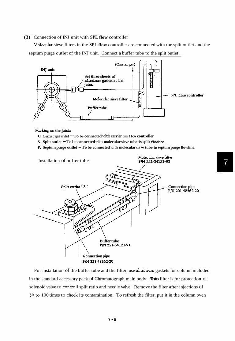
(3) Connection of INJ unit with SPL flow controller
Molecular sieve filters in the SPL flow controller are connected with the split outlet and the
septum purge outlet of the INJ unit. Connect a buffer tube to the split outlet.
Set three sheets of aluminum gasket at the
Mole& sieve filter SPL flow controller -T
Marking on the joints C. Cvrier gas inlet - To be connected with carrier gas flow controller S. Split outlet - To be connected with molecular sieve tube in split flowline. P. Septum purge outlet - To be connected with molecular sieve tube in septum purge flowline.
Installation of buffer tube Molecular sieve f i e r P/N 221-34121-93
Connection pipe P/N 20148562-20
Buffer tube P/N 221-34121-91 m Connection pipe
P/N 22148562-20
For installation of the buffer tube and the filter, use alminium gaskets for column included
in the standard accessory pack of Chromatograph main body. This filter is for protection of
solenoid valve to controll split ratio and needle valve. Remove the filter after injections of
50 to 100 times to check its contamination. To refresh the filter, put it in the column oven
7 -8

of high temperature (approximately 3OO0C), flow carrier gas and drive out the contamination
or refill molecular sieve (filler).
(4) Connecting carrier gas and make-up gas branch-off pipe
When used in the capillary split/splitless mode, the constant-pressure control method is
employed, in which the column inlet pressure is controlled. Connections with the INJ unit and
with the make-up gas flowline are done as shown below.
Resistance pipes are incorporated at each of the AIR, H2 and PI outlets.
At H2 outlet and PI outlet, make-up gas is merged with H2 gas via branch-
r off pipe 20148386, to be fed to - FID cell.
AIR pressure gauge FID c d AIR outlet
c
H2 pressure gauge Flow controller
outlet CFC- 14 PP
-3 P, cal-rier gar (PI ) pressure gauge outlet
41- To be connected with canier gas inlet “C” in INJ unit. cal-rier gas (P2) pz
pre-e gauge outlet
* Before setting this make-up gas branchoff pipe, check reading on the PI pressure gauge and the quantity of make-up gas fed to the PI outlet. (Flow rate of about 4 0 m ! h b can be obtained with N2 gas when the pressure gauge indicates 5OkPa.)
7 - 9

(5) Fitting the glass insert
@ B . . - _ - I
crd
I
I i
Remove nut @ and pull seal ring @ upward.
Then, O-ring @ is exposed. Replace the O-ring if
it is worn.
Using a pair of tweezers, extract ferrule holder
@ upward.
Insert glass insert @ fitted with graphite ferrule
@ into the injection port main body @ . Refer to the section on Construction of Injection
Port of SPL-14 to identify the numbers
assigned for these parts.
Reverse the above described steps to assemble,
with good care taken to see that the ferrule holder
@ is positioned in the right direction (with the
groove coming at the right position). The pipe used
at the septum purge outlet should fit in this groove.
To replace rubber septum used at the injection
port, remove nut @ and replace septum @) with P
a new one.
Press glass insert 9 securely so that its bottom
edge reaches the bottom of the evaporation
chamber.
If this is not enough, upper edge of the glass
insert touches the injection rubber valve. This
becomes the cause that normal septum purging
flow is not obtained and there may be ghost peaks
of septum.
I-. Insert @ with @ @ and press down.
7'- 10

P/N221-37574-01 PfN221-32544
For split injection For splitless method injection method
Fitting graphite ferrule @ Using the forming jig included in the accessory
pack, reform the ferrule with the following
sequence.
4 -8
4.7
4.6
Forming shaft
From around the outside diameter rp/ diameter of lassinsert of forming s t aft P/N P/N 221-35549.
Back ring
Cap nut P/N 221-32790 Graphite ferrule
P/N 221-12105
P/N 221-15563-91 1 Socket P/N 221-32510
As shown in the above fiiure, put the graphite
ferrule in the forming shaft and fasten its hexagonal
nut with a spanner. Then, take out the graphite
ferrule only and fix it in the glass insert.
The standard size of the graphite after forming
is that the hollow € 3 B from side rings is
mmJ 4 ~ 2 m m 2mm. The thickness
of the head of the forming shaft is 2mm. Measure
the hollow size by putting it in the hollow of the
graphite.
When the hollow is smaller than 2mm, remove some graphite on the back ring side with
tweezers to get the size. This is necessary for adjusting vertical positions of side holes of the
carrier gas inlet of the injection port and side holes of the ferrule holder.
(6) Type of glass insert
The SPL-14 is provided with two different glass inserts; one for split analyses, and the other
for splitless analyses.
For split analyses, glass insert having larger I.D. is used so that larger amount of sample can
be injected. For splitless analyses, glass insert having smaller I.D. is used to increase the linear
velocity.
7 - 1 1

Silica wool should be packed in the glass insert to prevent high boiling mist from entering the
capillary column and to mix vaporized sample sufficiently. It is appropriate to pack silica wool
at the position 1 or 2 mm apart from the needle tip at injection. If silica wool is too apart from
the needle tip, satisfactory reproducibility may not be obtained.
Position of silica wool (length (A) in the figure) depends on the needle length of the syringe
used and whether auto injector is used or not. Positions of silica wool in different cases are listed
in the following table for reference.
s usually, this shorter side is placed upBut, turn it upside down when a large amount of silica wool is to be packed
z
/ ilica wool
Pack 3 to 6mg of silica wool to a depth of 5 to 1Omm. Do not squeeze it into tighly.
# 1.2 I. D. - - # 3.4 I. D 3
Table
' Sica wool
n Be careful not to fluff silica wool. Pack it uniformly.
Injection by
' Needle len,@h of syringe for AOC- 14/17 is 43mm
AOC- 14
1 Injection by AOC-17
Needle ]en,* of syringe for AOC- , 14/17 is 43mm.
Manual injection using syringe for
(needle length is 43mm.)
AOC-14/17
Manual injection using 50mm- long needle
Position of silica wool (dimension (A) in mm)
20mm 23mm 27mm 35mm
7 - 12

The above table indicates standard positions and weights of silica wool. For some
particular samples, better result may be obtained by changing the amount of silica
wool as follows.
1. For samples, such as agricultural chemicals, which have high adsorptivity,
better result may be obtained by packing smaller amount of silica wool than
listed.
For solvents, such as water, which have large latent heat of vaporization, better
result may be obtained by packing larger amount of silica wool than listed.
2.
[I\ :.:.:..., .,... ..:. ...... .... :.
........ ...., . . . ~ .... . ..
Silica wool may be dislocated due to fluctuation of carrier gas flow rate during
replacement of injection port septum or replacement of column. Before replacing
injection port septum or column, return the inlet port pressure of the column to the
atmospheric pressure. After replacement, return the inlet port pressure of the column
gradually to the set pressure.
When injection is made manually in the INJ unit using AOC-14/17 (INJ unit in which
silica wool position is adjusted for AOC- 141 17), use a syringe for AOC- 1 4 17.
To inject manually using a syringe for AOC-14/17 with silica wool at the same
position as in AOC-14/17, insert an injection port septum into the bottom of the
needle.
- Insert an injection port septum
Insert an injection port septumwith / - its lower port cut off.
Manual injection when usinn AOG14
jbr ::.:... ..".$ .I...... :...:. ....
Manual injection when using AOC-17
u
cut off this part i-Y
7 - 13
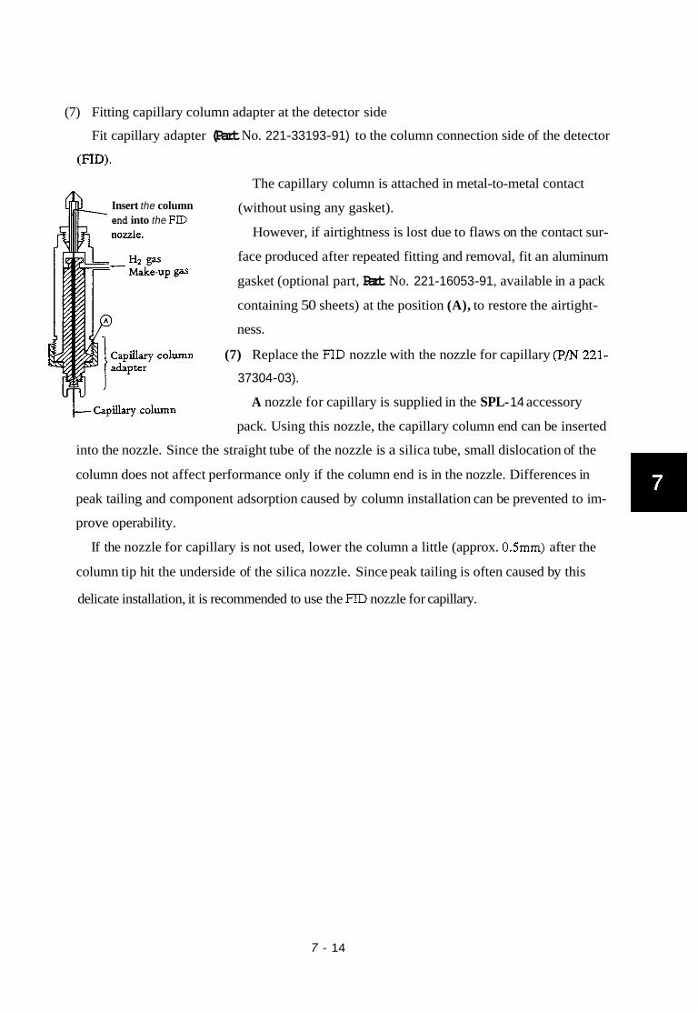
(7) Fitting capillary column adapter at the detector side
Fit capillary adapter (Part No. 221-33193-91) to the column connection side of the detector
(RD).
Insert the column end into the FID
The capillary column is attached in metal-to-metal contact
(without using any gasket).
However, if airtightness is lost due to flaws on the contact sur-
face produced after repeated fitting and removal, fit an aluminum
gasket (optional part, Part No. 221-16053-91, available in a pack
containing 50 sheets) at the position (A), to restore the airtight-
ness.
(7) Replace the FID nozzle with the nozzle for capillary (P/N 221-
37304-03).
A nozzle for capillary is supplied in the SPL- 14 accessory
pack. Using this nozzle, the capillary column end can be inserted
into the nozzle. Since the straight tube of the nozzle is a silica tube, small dislocation of the
column does not affect performance only if the column end is in the nozzle. Differences in
peak tailing and component adsorption caused by column installation can be prevented to im-
prove operability.
If the nozzle for capillary is not used, lower the column a little (approx. 0.5mm) after the
column tip hit the underside of the silica nozzle. Since peak tailing is often caused by this
delicate installation, it is recommended to use the FID nozzle for capillary.
7 - 14

(8) Fitting the column holder
The column holder is included in the accessory pack, divided into two sub-assemblies, one
consisting of the parts @ to 0 , and the other consisting of the parts @ to @) .
To install the column holder inside the gas chromatograph oven, insert the threaded portion of
hook @ into the wire mesh as shown in the figure and fasten it with the supplied screw.
When two capillary holders are fixed, fix the fkst holder with this spacer and fix another holder to the threaded portion of the spacer.
Column holder assembly Part NO. 221-31567-91 - - 11 12 13 14 15 16 17 18 19 20 21 -
Description
Arm Guide, Arm Fixing screw Nut
Screw Washer Stopper Post Mounting bracket
Screw, M4X 8 Spacer
PIN 22 1-3 1 568 22 1 -3 1 56 9 22 1 -3 1 57 0 22 1-3 157 1 22 1-3 1 572 023-7705 0 026-66204 221-31573 22 1-32146 020-46535 22 1-34015
Set it at the central part in the oven, e.g. at around the center shaft of the fan motor, and
fasten it securely.
The remaining parts @ to 0 (in a sub-assembly) are fit to the post @ with screw @ after the column is set on the column holder. The arm @) , when assembled, is so constructed
that the coil diameter held can be changed as desired in the range of lOOmm and 22Omm.
7 - 15

(9) Mounting column
I
Graphite ferrule PIN 221-32126-05
r=* Extract core wire and
pass it through to reach the end of the capillary column.
L J
(Injector side) (Detector side)
I I
Q
E E In b
m
Injector side Detector side
7 - 16

3. Construction of SPL-14 injection port
Construction of the injection port is shown on the left. It is so constructed that the
glass insert inside the evaporation chamber can be
replaced through the injection side.
Note. This septum purge flowline may not be formed correctly if the glass insert is dislocated upward, resulting in ghost peak of septum. Insert the glass insert deeply into the vaporization chamber. hI - Septumpurgeout
Note. Tighten the nut @ securely not to allow clearance at this section. If the flowline is cut short at this section, septum purge will lost its effect. ---- split out
- 1
2
3
4
5
6
7
8
9
10
11
12 -
Description
Needle guide
Septum holder A
Septum
Nut
Seal ring
O-ring
Ferrule holder
Graphite ferrule
Glass insert split
Glass insert splidess
Gasket
Column joint metal Main body of evaporation chamber
P / N
221-34579
22 1- 32538
201- 47435
221- 32539
221- 32540
036- 11013
22 1- 32541
221- 15563- 91
221-37574-01
2 2 1- 32544
2 2 1- 32543
221- 32542
221- 32535- 91
Fig. 7.10 Injection port of SPL-14
. .
7 - 17

4. Construction of SPL flow controller
//
//
Q Q VENT
split flowline
N 0.
1
2
3
4
5
6
7
8
10
11
12
13
14
~
Description
Pipe GF-MF
Mole& 6eve filter
Pipe MM-MF
Solenoid valve US-5M-37
Pipe M5-MF
Needle vdve, spbt
Needle vdve, septum purge
Pipe GLMF
Pipe GFGF
Buffer tube
Molecular sieve fdter
Pipe M5-GF
Pipe GF-GF
3 1 ~ Septum purge flowline
P I N
201 -48560-50
201-36992-91
201 -48557-30
040- 50271
221- 32428- 91
221- 17482
221- 26995
221- 31298- 91
201-48562-20
221- 34121-91
221- 34121-93
221-32428-92
20 1 -48562-25
7 - 18

5. Operation of SPL-14
/ Split gas
/ Select switch
outlet Purge gas outlet
Pressure regulator PZ
( / 7 T Carrier gas flowline
Septum purge flowline
1 Split flowline . . . , .. , . . . . _ . , . . . . . . . . . - :.:.
Filter Solenoid valve
1) Control parts of the SPL-14 are shown in the above figure.
When the power switch for the gas chromatograph is turned on and the SAMPLING-
ANALYSIS select switch is set at the SAMPLING side, power is supplied to the solenoid
valves and the indication lamp is lit up. At this time, the split flowline is blocked.
7 - 19

When analysis is made in the split method, this select switch is to be set at the ANALYSIS
side at all times.
When analyzing in the splitless method, sample is injected with the select switch set at the
SAMPLING side, and then it is shifted to the ANALYSIS side when a certain period of time
has elapsed.
Procedures to be taken after fitting the column are explained in the following paragraphs.
Pressure should rise gradually by turning the control knob on the side clockwise, while
observing the pressure of carrier gas (Pz) on the pressure gauge. Set to optimum pressure
according to the Table below, to match the inside diameter and length of the capillary column
used. (The figures shown in the Table are for the case where helium is used as the carrier gas.)
2)
0.20 mm
0.25 mm
0.30 mm
0.50 mm
25m 50m
300kPa 1 SOkPa
13OkPa 250kPa
1 OOkPa 200kPa
SOkPa 1 OOkPa I I
When the pressure is set properly, the linear velocity of carrier gas inside the capillary column
should become the appropriate flow. As those figures shown above are given as a guideline,
make further fine adjustment as necessary.
3) Shift the select switch to ANALYSIS. (The indication lamp should go out. Connecting
a soap film type flow meter to the VENT port, and adjust with the control knob so that flow
rate in the septum purge flowline and that in the split flowline will become 5 to lOmll/rnin and
to 40 to 80mP/min, respectively.
4) Setting temperature in the injection port
Setting of temperature in the injection port greatly affects the result of measurements.
A too low injection port temperature tends to prolong the analysis time, or will result
poor recovery rate of high b o d q temperature substances. Conversely, a too high injection
port temperature is likely to cause distillation effects at the syringe tip, to degrade the
reproducibility. So, it is necessary to select optimum temperature for the injection port
according to the boiling point of the substance aimed at and the kind of solvent used for the
sample. Generdy, it seems to be appropriate to operate with the temperature set in the range
from 200 to 300°C.
7 - 20
5) Setting column initial temperature
Setting of column initial temperature is especially important in the splitless sample injection
method. To make best use of the solvent effect, the initial column temperature is set 10 to
40°C lower than the boiling point of the sample solvent. In the case of a high boiling point
substance, which does not need the solvent effect, the column initial temperature is selected at
temperature 150 to 200°C lower than the boiling point of the target component(s).
6) Determination of wait time
Another important factor on which reproducibility of analysis is dependent is the wait time,
the time period from injecting sample till the opening of the solenoid valve. After injecting
sample with the select switch being set at the SAMPLING side, wait for a predetermined period
of time before switching over to the ANALYSIS side. If this wait time is too short, there wil
be large loss in the high-bohg point substances, whereas too long a wait time may cause
expansion of peaks of low-boiling point substances. By observing the changes in peak areas
with time, it is known that the high boiling points substances enter the capillary column requir-
ing fairly long period of time.
To cope with this problem, it is necessary to take appropriate measures, for example, by
extending the wait time, or by increasing the carrier gas flow rate, or by raising the temperature
in the injection port.
Normally, wait time is set between 0.5 and 2 minutes.
In order to obtain good reproducibdity, it is essential to maintain the wait time at a constant
value for each repeat analysis.
7 ) Determination of make-up gas flow rate
When detection is made with the FID after leaving the capillary column, inert gas is added
to obtain optimum sensitivity. As in the case of carrier gas, helium can be used as the make-up
gas. Alternately, nitrogen can also be used for this purpose, separately from its use as the
carrier gas. Nitrogen allows shghtly better sensitivity than that obtainable with helium gas.
When other types of detectors than FID are used, it is also necessary to add make-up gas in
oder to prevent expansion of peaks that may otherwise occur at the connections between the
detector and the capillary column. Kind of the gas used and flow rate should be determined
properly depending on the actual detectors used for analysis.
(Example: ECD ... N,, FTD ... He, FPD ... N, or He)
7 - 21

8) sample injection rate
When the splitless sample injection method is used, flow rate of the carrier gas at the time of
sample injection is fairly low, measuring about 1 to 2mPlmin. Therefore, if a liquid sample is
injected in a large volume, it will evaporate and increase its volume, to flow backward in the
carrier gas flowline, causing it to deposit on the wall of the flowline. In the splitless injection
method, the normal quantity with which sample can be injected at normal speed is about 11.111.
If it is necessary to inject sample in higher quantities, some considerations are necessary, for
example, by pushing the plunger slowly and by increasing the flow rate of the carrier gas.
9) Selection of solvent
When analyzing high boiling point substances, it is advantageous to use solvents of relatively
high boiling points, like decane (Clo) or tetradecane (C14). When such kind of solvent is used,
there is little distillation effect occurring at the tip of the syringe, even if it is injected slowly,
enabling determination with good reproducibility. Furthermore, initial temperature of the
column can be made higher, thus shortening the analysis time.
In case of analysis involving a sample containing many components ranging from low to high
boiling points, it is inevitable to use solvent of the lower boiling point than that of the target
component(s). In the case of such analysis, it is often advantageous in terms of rgliable re-
producibility and determination, to introduce low sample volume in an as quickly as possible
injection operation.
It is generally said that paraffins or acetone, etc. should preferably be selected as solvent for
assured long life of the liquid phase in the column, avoiding use of aromatics or polar solvents
for the purpose.
10) Routine operations (in the case of splitless injection method)
Once optimum analytical conditions have been decided (as to the flow rate, temperature
condition, injection rate and wait time), routine operations for analysis are to proceed as follows.
(1)
(2)
( 3 )
(4)
(5)
Confirm that the column oven temperature is stabilized at the set initial temperature.
Set the select switch at SAMPLING.
Inject sample via a microsyringe.
Start up heating* and the data processing unit.
**Wait for a predetermined period of time. (Wait tU the sample shifts to the capillary
column.)
( 6 ) **Set the select switch at ANALYSIS.
7 - 22

* I t is necessary to set the time period during which the column to be held at the set initial
temperature (INITIAL TIME) longer than the WAIT TIME.
* * For the SPL-14, these operations can be automated by using a time program. (Refer to
12 to follow.)
11) Use as a splitter
Changing the glass insert to the one intended for splitting (of 3.4mm I.D. with its one end
reduced to 1.2mm I.D.), inject sample with the sampling switch set at the ANALYSIS position.
Split ratio can be changed by turning the control knob for the needle valve in the SPLIT fI ow-
line. Measure the split ratio by connecting a soap film type flow meter to the VENT port.
12) Case of operating solenoid valves for the SPL-14 using a time program:
The solenoid valves used in the SPL-14 are connected as shown in the circuit diagram shown
below.
L I lOOV AC I SAMPLING -
I
- To be connected with relay contacts for EVENT 91 in the GC main body. Relay “91”
Accordingly, when this solenoid valve is to be operated via the time program functions
provided for the GC main body, the solenoid valve SVl can be turned ON and OFF
via relay for EVENT 91, with the select switch set at ANALYSIS side. Even in this case, the
indication lamp for monitoring the status of the stop valve is working effectively. That is, it
indicates that the unit is then in SAMPLING state when the indication lamp is on, and indicates
ANALYSIS state if the lamp is turned off. Key operations needed for standard time program
are as follows:
7 - 23

With the above key operations, ANALYSIS state is entered automatically in two minutes
after starting injection and pressing the START button.
Needless to say, it is necessary to make key operation as shown below immediately before
injecting sample to recover the SAMPLING state. (This can also be time programmed.)
13) Handling precautions
(1) When the glass insert has been replaced with a new one, there may a possibility of peaks
resulting from surface soiling or otherwise in the next round of analysis. To avoid this,
a blank test must always be conducted prior to the starting of actual analysis.
(2) Residue of sample deposited on the glass insert, if any, should be washed out with the
proper solvent without fail.
(3) In some cases of splitless injection, column oven temperature may be lowered at the time
of injection, and then raised abruptly at the time of analysis. If applied in such an operation,
the column and the related parts made of PEG m a t e d may be damaged as they are suscepti-
ble to thermal shocks.
(4) If initial temperature of the column oven is too low, there may be a possibility of the
liquid phase in the column being dissolved in the sample solvent.
(5) In case of a sample including components of wide boiling point range, the injection
technique will have serious influence on the result of measurement.
Generally speaking, the injection method called “cold needle method” is adequate for the
purpose. (Let air be drawn through the needle of the syringe. After sticking the needle tip
into the septum, press the plunger promptly to inject sample. Extract the needle tip after
5 seconds or so after injecting the sample.)
7 - 24

5. Maintenance
Peaks of low boiling point substances expand.
Routine maintenance
(1) In order to protect the needle valves inside the flow controller, molecular sieve filter tubes
are provided. Condition those filter tubes once a month.
Clean the glass insert with proper solvent at regular intervals.
In case of a high-sensitivity analysis, condition the graphite ferrule before use without fail.
Some solvents may damage the liquid phase in the column.
There may be a case, where the liquid phase at the tip of the column may flow out as a result
(2)
(3)
(4)
(5)
of repetitious splitless sample injection, degrading peak shapes. In such a case, cut off part of
the column by 50cm or so from its tip and reconnect it in place.
Lower initial temperature of column.
Change to solvent with higher boiling point.
Exchange column.
Troubleshooting
Symptom Countermeasure I
Peaks of high boiling point substances appear
small. ~
T d i n g of solvent peak is large. x *Extend wait time.
Raise temperature in injection port.
Increase flow rate of carrier gas.
*Insert capillary column farther into the injection port.
Increase split flow rate.
Increase septum purge flow rate.
*Decrease injection rate.
Heavy ghost peaks appear. Condition graphite ferrule.
*Increase septum purge flow rate.
Clean glass insert.
Clean carrier gas flowline.
0 Insert molecular sieve in the carrier gas flowline.
7 - 25

221-4001 &08
8. Flow Controller
The flow controllers of the GC-14B series are separate units. Description will be made on typical
flow controller units.

1. Introduction
Carrier gas, hydrogen gas for the flame ionization detector, air for supporting combustion, and
others are required for the operation of the gas chromatograph. The accuracy of the gas supply unit
has a direct effect on the accuracy of analysis by the gas chromatograph and the flow controller
is an important component of the chromatograph system.
The flow controller which is being outlined is a unit developed for gas chromatography permitting
setting up an optimum arrangement for analysis and easy extension of the flow control system.
1.1 Gases used for gas chromatography
Detector
Thermal conductivity detector (TCD) Gas with thermal conductivity considerably different from that of sample is generally used as the detector perceives the differ- ence in thermal conductivity between carrier gas and sample.
Hydrogen flame ionization detector (FID) Hydrogen and air are required in addition to carrier gas for mixing carrier gas with hydro- gen and burning the mixture by supplying combustion support air.
Flame photometric detector (FPD)
Flame thermionic detector (FTD)
Electron capture detector (ECD)
Type of Gas
Carrier gas o Helium (most optimum) o Hydrogen (requiring
o Nitrogen (usable but careful handling)
low in sensitivity)
Carrier gas o Nitrogen (most opti-
mum) o H e h m (usable) Combustion gas o Hydrogen o Air
Same as FID
Carrier gas o H e a m (most optimum) o Nitrogen (usable) Others same as FID
Nitrogen gas
Purity
99.99% min.
99.99%
As high a purity as possible. Supply compressed air from an oil-less air compressor after removing moisture.
Use air from cylinder.
99.999% min.
8 - 1

1.2 Cautions about high pressure gas cylinders
High pressure gas cylinders are used as gas supply sources. Handle them carefully according to
the cautions and guidance given by the high pressure gas cylinder supplier for preventing an
accident.
(1) Place cylinders in an outdoor place of good ventilation protected from the direct rays of the
sun and lead gases in by piping. This is compulsory in some countries when liquified gases are
used.
( 2 ) The temperatures of gas cylinders should be always kept below 40°C. Open flames must be
kept away; at least 2m from gas cylinders.
( 3 ) When high pressure gases are used, maintain good vendation and check for gas leakage with
soapy water, etc., before starting up the system. No smoking or use of open flames is permitted
within 5m from the apparatus when flammable gases (for instance, acetylene, hydrogen and
propane) or combustion supporting gases (for instance, oxygen and nitrous oxide) are used.
Provide effective fire extinguishers also.
(4) Secure cylinders with a rope or the like so that they can not fall down. Liquefied gas cylin-
ders (acetylene, propane, liquefied carbonic acid, nitrous oxide and others) must not be thrown
down on their side.
( 5 ) Use an oil-free reducing valve for the oxygen gas cylinder. Make sure that the interiors of
the tubes and others coming into contact with oxygen are free from oil.
(6) Close the shutoff valve of the cylinder immediately after ceasing the use of the gas.
(7) Check the pressure gauges for function, at least every three months.
(8) We are sticking aluminum plates stating cautions about hydrogen gas handling to our products
delivered to the users. If the plate is required urgently, contact us. We will send it free.
Pay attention to your national or local regulations on high pressure gases. Total amount of
gases to be stored or maximum pressure of gases may be limited.
Exercise care in the following points for preventing a hazard when hydrogen gas is used.
-1 Warning in using hydrogen
(1) Close the shutoff valve of the hydrogen gas cylinder and ascertain that the
gas does not leak from the valve when the system is not used.
Check the hydrogen flow line from the hydrogen gas cylinder to the final
outlet port through the apparatus for leakage every time hydrogen gas is
used.
(2)
8 - 2

(3) Ventilate the room and don’t use open flames unnecessarily in the room
where the system is installed to prevent hydrogen gas explosion by an
accident.
Close the shut off valve of the hydrogen gas cylinder immediately up on
completion of operating the apparatus, and switch off the power supply of
the nearby apparatus before following other steps to be done at the end of
operation.
( 5 ) Install the protective blind caps to the connection port of the column and
detector when the FID is not used.
(4)
2. Components of Flow Controllers
The flow controller is accommodated in a separate case from the gas chromatograph proper.
The controller is avadable in the following types according to the internal flow line arrangement.
a. Model CFG14PM
This type is equipped with one pressure regulator and one mass flow controller for the carrier
gas flow line, two pressure regulators for the FID flow line, and one pressure gauge for each flow
line.
b. Model CFC-14P
This type is equipped with two pressure regulators for the carrier gas flow lines, two pressure
regulators for the FID flow lines, and one pressure gauge for each flow line.
c. Other types
Other types are outlined in Para. 2.3.
lkPa = 1.02 x 10⁻²kgf/cm’
1 k&m2 = 98. lkPa
8 - 3

2.1 Flow controller - - model .._ CFC-l4PM, P/N 221-41 - - 806-91
The flow controller regulates the flow rate of carrier gas (mass flow control) and is most suitable
for the packed column single flow line.
Fig. 84A CFC-14PM
Leak valve diminishing air flow rate
Air flow line Air resistance tube built in
Hydrogen flow line Hydrogen resistance tube built in
I I
I Branch pipe I
T
Carrier gas IN 33-J (mass flow control)
OUT
I-- -- J P : Pressure regulator
M : Mass flow controller
4, : Full scale lOOOkPa pressure gauge
:
@ :
Full scale 600kPa pressure gauge
Full scale 200kPa pressure gauge 8
Fig. 84B Flow line diagram
8 -4

Application Example 1 - For Packed Column
Iniection port FTn
CARRIER IN
Set carrier gas pressure regulator SO that pressure gauge reading shall be 5OOkPa when primary pressure is controlled by regulator. 0 Carrier gas regulated to constant pressure is acquired by
branch pipe. 0 Carrier gas is supplied from branch pipe to injection port
evaporation chamber for regulating column inlet pressure of carrier gas to given level.
CARRIER IN
Branch pipe SO that pressure gauge reading shall be 5OOkPa when primary pressure is controlled by regulator. 0 Carrier gas regulated to constant pressure is acquired by
branch pipe. 0 Carrier gas is supplied from branch pipe to injection port
evaporation chamber for regulating column inlet pressure of carrier gas to given level.
Fig. 85 Application example for a packed column
When the carrier gas flow line is regulated to a constant flow rate (mass flow control), the flow
rate of carrier gas entering the detector is maintained constant and change in the sensitivity of the
detector is prevented though the column resistance is changed with the rise of column temperature
in temperature programmed analysis.
Carrier gas may be regulated in pressure (by the pressure regulator) when temperature program-
med analysis is not made, as the column temperature is constant and the flow rate of carrier gas
does not change during analysis. Pressure regulation is rather preferable when a part changing in
inner volume such as a gas sample valve is connected to the upstream side of the column.
Change in pressure due to valve switching is prevented and the fluctuation of the baseline by
pressure change is minimized.
8 - 5

Application Example 2 - For Packed Column and TCD
esistance column
Fig. 86 Application example to packed column and TCD
The reference flow line of the TCD is arranged in one of the following methods.
1. The reference flow line is set up by connecting the resistance column to the port A of the
branch pipe connected to the down-stream side of the primary pressure regulator. In this case,
set pressure so that the reading of PI is higher by at least 50kPa than that of the column inlet
port P2.
2. The port A of the branch pipe is connected to the port H and the reference flow line is set
up by connect the port B to the port C by utilizing the FID hydrogen pressure regulator.
3. The GC-14A provided with the TCD is equipped with a resistance tube (P/N 221-33431-91)
as a substitute for the resistance column. The resistance tube provides a flow rate of 40mQ/min
(helium gas) at an inlet pressure of 5OOkPa
8 - 6

Application Example 3 - For Dual Flow Lines and Dual Columns
CFC-14PM
. '=
CFC-14PM
Fig. 87 Application for dual columns
In dual flow line and dual column arrangement, two model CFG14PM flow controllers are used
in parallel. Whereby a complete dual flow line and dual column system is set up.
8 - 7

2.2 Flow controller model CFC-I4PP, P/N 221-41805-91
This flow controller regulates the flow pressure of carrier gas constant (pressure control) and
is most suitable for capillary column analysis.
Fig. 88A CFC-14PP
I Leak valve for reducing air flow rate at FID ignition
Air flow line Air resistance tube built in
Hydrogen flow h e drogen resistance tube built in
Carrier gas pressure regulator PI
ydrogen resistance tube built in 3 Branch pipe
Carrier gas pressure regulator Pz
Fig. 88B Example of flow lines
1 Note I The outlet port of the carrier gas pressure regulator PI is equipped with a resistance
tube (indentical with that equipped in the hydrogen flow line). If gas is discharged
from the outlet port via the resistance tube, a flow rate of 40mZlmin is acquired for
nitrogen gas at a pressure gauge reading 5OkPa.
8 - 8
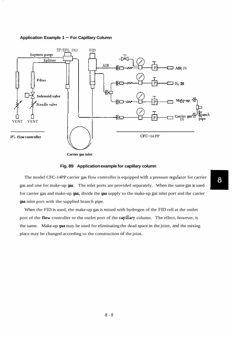
Application Example 1 - For Capillary Column
SPISPL INJ FID
y y ----- I Solenoid valve
t I VENT VENT
;PL flow controller
AIR IN
HZ IN
b Carrier gas inlet
Make-up
0 Carrier IN gas P Branch IN Pipe
CFC- 14 PP
Fig. 89 Application example for capillary column
U The model CFC-14PP carrier gas flow controller is equipped with a pressure regulator for carrier
gas and one for make-up gas. The inlet ports are provided separately. When the same gas is used
for carrier gas and make-up gas, divide the gas supply to the make-up gas inlet port and the carrier
gas inlet port with the supplied branch pipe.
When the FID is used, the make-up gas is mixed with hydrogen of the FID cell at the outlet
port of the flow controller or the outlet port of the cap% column. The effect, however, is
the same. Make-up gas may be used for eliminating the dead space in the joint, and the mixing
place may be changed according to the construction of the joint.
8 - 9

2.3 Other flow controllers
Other flow controllers of different combibations of pressure regulators and mass flow controller
from those outlined in Para. 2.1 and 2.2 are available. Those controllers are options as they can
be substituted for the controllers outlined in Para. 2.1 and 2.2. (The FPD flow controller model
FpFC-14, however, is a standard unit for the chromatograph equipped with the FPD.)
(1) Carrier Gas Flow Controller Model CFC-14, P/N 221-32233-91
The flow controller incorporates a primary pressure regulator and two mass flow controllers.
It is also provided with a space for installing one pressure regulator and one pressure gauge as
standby instruments.
CARRIER 1 CARRIER 2 PRIMARY -7 7 7 AUX
\ CFC-14 Flow line diagram - -- 7-- ! CARRIER IN
I
I I CARRIER OUT @
( 1 ) I I
CARRIER OUT ( 2 )
I -- -- 1
Fig. 810 FCF-14 I
8 - 10

(2) FID Flow Controller Model FFC-14, P/N 221-32234-91
The controller regulates hydrogen and air for the FID.
HYDROGEN1 AUX -\ , \
HYDROGEN2 1- I AIR \ \ I I .
\ FFC-14
Flow line diagram
Hz IN Hydrogen
H z 2 OUT
I - , I Hydrogen resistance 2K itube built 200kpa
AIR OUT b-w-Eb-4 AIR IN
Air resistance tube built in
Fig. 811 FFC-14
8 - 11

(3) Flow Controller Model FpFC-14, P/N 221-32235-91
The controller is designed to regulate hydrogen and air of the FPD.
HYDROGEN / A I R I
\ FPFC-14 Flow line diagram
r -- -- 7 I
Hz OUT
AIR O U T c AIR IN
FGD air resistance tube built in
Fig. 812 FpFC-14
8 - 12

3. Specifications
Overall dimensions
Designation
Front
Secondafy pressure Maximum Max. re&Mg range I inlet press Accuracy flow rate
~ L
M S S flow controuer 1 Inlet press
P/N 221- 3 2 2 3 8 - 91 SOOkPa
Rear
h.
2oorn~lrnin Accuracy flow rate
fluctuation Less than 1% ofsecondary against 80% resistance
Weight: 2.6kg when four pressure regulators are built in.
Fig. 813A
Gas inlet and outlet port fitting dimensions
0 m 1#Tao 4
MlOPl
(Flow controller)
Fig. 813B
Pressure redators
(Connection pipe)
Fig. 813C
IPlmin Less than 1% inlet pressure fluctuation
2K pressure regulator PM 221-18150-91
6K pressure regulator P/N 221-18150-92
I1
8 - 13
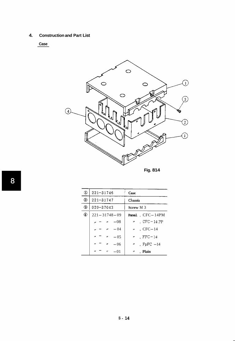
4. Construction and Part List
@
Case
221-31748-09 Panel , CFC-14PM
N - -08 /’ , CFC-14PP
I, - -04 , CFC-14
’1 -05 // , FFC-14
’’ -06 // , FpFC -14
” -01 ” , Plain
/I - I, - I, -
Fig. 814
Screw M 3
8 - 14

Pressure regulator and mass flow controller flow line parts
Part Number
@ 221- 32238- 91
Fig. 815
Part Name
Mass flow controller with filter
W
Fig. 815
Pressure regulator flow line
Ref. No.
1
2
3
4
5
6
7
8
9
10
Part Number ~
221- 18150- 92
221-18150-91
6 7 0-1 8 5 58-14
67 0-1 8 558- 13
6 7 0- 18558- 12
670- 18558- 11
221- 31739- 93
221- 09864- 18
201- 30211- 02
2 0 1-468 33
221-31745
221- 19502- 08
201- 35584 (20 pclpackage)
20 1-4 8386
Part Name
6K pressure regdator (for c k e r gas)
2K
IOOOkPa pressure ,oauge
6OOkPa pressure gauge
300kPa pressure gauge
200kPa pressure gauge
Pipe PG-h4.F-MF
Pipe MF-Mh4L-17
Washer
Nut
Resistance tube socket
Resistance tube (for hydrogen)
Rubber septum (utilizing injection port septa)
Branch pipe
(for FID hydrogen and air)
The resistance tube @ and septum @) are used only for the hydrogen flow line and make-up
flow line.
8 - 15

FID and FPD air flow line parts of pressure regulator flow lines
Ref. No
1
2
3
4
5
6
7
8
9
10
11
12
13
Fig. 816
Part Number
221-18150-91
6 7 0-1 8 5 58- 11
221-31738-92
221- 09864- 18
201-30211-02
201- 46833
221- 31745
221-19503-08
221- 19502- 06
20 1- 35584 (20pclpackage
016- 31350- 07
221- 32848
20 1-3 0 2 4 8
221- 32849
Part Name
Pressure regulator (2K)
Pressure gauge 200kPa
Pipe PG-MF-MF42
Pipe MF-h4MG17
Washer
Nut
Resistance tube socket
Resistance tube (for FID air)
Resistance tube (for FPD air)
Septum (utilizing injection port septum)
Silicon rubber tube 1 X 3 X 2 5 h m
Shaft
spring
Pin
8 - 16

221 -4001 0-09
9. Capillary Column Assembly (Option)

1. Capillary Column Holder CLH-14 (P/N 221-32995-91)
1.1 Description
The CLH-14 capillary column holder allows the modification of packed column chromatographs
(GC-l4B, GC-lSA/ 16A) to splitlsplitless capillary column configurations. The holder will accept
narrow-bore, middle-bore, semiwide-bore, and wide-bore fused silica capillary columns with inner
diameters of O.lmm, 0.22mm, 0.33mm, and 0.53mm, respectively. The maximum outer diameter
of the capillary column which can be accommodated by this holder is 0.8mm.
1.2 Specifications
(1) Maximum column coil diameter:
(2) Maximum column length:
(3) Maximum column outer diameter:
(4) Column type:
(5) Applicable GC:
22cm
5 Om
0.8mm
Fused silica capillary column with cage
Shimadzu Gas Chromatograph models GC-l4B, GClSA,
GC-16A, GC-9A, GC-l2A, and GC-7A
1.3 Structure
This holder includes splitter, split ratio adjustor, and column connection components.
All components are shown and listed in Fig. 1 and Table 1, respectively.
9 - 1

J The split ratio adjustor is installed on the left side of gas
\ I
0 chromatograph main body.
P P
c b
w \
Oven backplane mesh
1
' Capillary column
Fig. 1 Construction of CLH-14 (No. 1)
When the split ratio adjustor is installed on the left of the main body
9 - 2

INJ side
1
For the GC-14B series, split ratio adjusting unit can be installed in the top slot of the control section using the attached panel.
Fig. 2 Construction of CLH-14 (No. 2)
When the split ratio adjustor is installed in the top slot of the control section
(GC-14B series only)
9 - 3

Table 1 Parts List for CLH-14 (221-32995-91)
Ref. No.
7
8
9
1 0
1 1
1 2
1 3
1 4
1 5
1 6
1 7
1 8
1 9
2 0
2 1
2 2
2 3
3 1
3 2
3 3
3 4
3 5
~~
Name of part
Glass insert INJ 0.8
Graphite ferrule 5mm
Splitter joint
Graphite ferrule 0.5
Capillary joint nut (Slotted)
Column holder
Needle valve holder plate
Buffer
MS-5A fdter
Nut
Washer
Needle vdve
Knob
SUS bolt M4 X 16
Graphite ferrule 4mm
Side ring
Back ring
Cap nut M4
Glass insert DET
Graphite ferrule 5mm
Splitter joint
Graphite ferrule 0.5
Capillary joint nut (Slotted)
Pipe MF-MM 250
Pipe GL-MF
Nut
Pipe MF-MM 700
Panel CLH-14
~
Part No.
22 1 -329Y8-0 1
221-15563-91
221-32480- 91
2 2 1 - 3 2 1 2 6 - 0 5
221-32705
221-3 1567-91
221-33001
221-32997
22 1-32996-91
201-46833
201-30211-02
221-17482
037-024 0 1-01
020-4651 1
22 1-23160
221-21922
221-23161
201 -30008-04
22 1-33000
22 1-15563-9 1
221-32480-91
221 -32126-05
22 1-32705
201-48557-25
221-3 1298-9 1
20 1-48464
201-48557-70
22 1-33464
Q'ty.
1
1
1
1
1
1
1
4
1
1
1
1
Remarks
Note 1
Note 2
Note 3
Note 4
Note 1
Note 2
Note 3
Note 4
Note 1
Note 2
Note 3
Note 4
As standard, one set of 5mm graphite ferrule @ and 20 containing four pieces is provided.
As standard, two splitter joints @) and 21 are provided.
As standard, one set of 0.5mm graphite ferrules @ and @ containing 10 pieces is provided.
As standard, two capillary joint nuts @ and @) (Slotted) are provided.
9 - 4

2. Components for Capillary Column Flowlines
The following flowline components are used for constructing the appropriate flowline for capillary
analysis.
(1) Capillary adaptor P/N 221-32480-91
SUS304T 2 @ x l b x 2 5 0 r n m I (2) Graphite ferrule for the capillary column
(One set provided containing 10 pieces)
G-0.5 PIN 221-32126-05
G-0.8 P/N 221-32126-08
(31 Capillary column nut \ Slotted nut (8>7 P/N 221-32705
0 - (Large)
Non-slotted @T P/N221-16325-01 (s /
141 Dud column adaptor P/N 221-32485-91
Application example
Glass insert (with outer dia- meter of 5mm) is inserted from the column oven side of the standard packed column irjec- tion port which is connected to the capillary column via this adaptor.
Graphite ferrule A to be attached to the glass insert should be P/N 221-15563-91 (one set provided containing four pieces).
Capillary column
' I Two capillary columns can be installed. See the installation example below.
Capillary column

Name of part (P/N)
(5) Dual column adaptor for SPG14 P/N 221-33487-91
M 6
(6) Adaptorjoint C-MM-m P/N 221-32489-91
P = l
(7) Adaptor joint C-GMM-MF P/N 221-32491-91
Application example
If the column joint of INJ unit P/N 221-32547-91 of the SPL-14 is replaced with this adaptor, two capillary columns can be installed as in (4).
I INJ unit S P L - I ~ I
Use an aluminum packing P/N 221-32543.
This adaptor allows connection to a glass tube of 5mm outer diameter.
Glass column joint P/N 221-15561-91 m
9 - 6

Name of part (P/N)
(8) Branch joint, detector P/N 221-32515-91
Holder
Stainless wire 1$ i-" (Fd size)
Application example
This adaptor branches the outlet of the capillary column to provide flow to two detectors. A make-up flowline is provided at the branch.
Holder T
I Cross section of branch
Capillary tube /
Purge - gas 7'"" ' 1) IF capillary column
d Column
9 - 7

Name of part (P/N)
(9) Nut MM P/N 221-32510
I \ M l O P = l
UO) Adaptorjoint C-Mh4 P/N 221-32490-01
(11) Adaptor joint C-C-MM P/N 221-32491-92
(12) Adaptor nipple C-MN PIN 221-32509
(13) Adaptor nipple CGN PIN 221-32508
Application example
Glass tube with outer diameter of S@
- Graphite ferrule for glass column
Capillary adaptor
These adaptor joints ( 6 ) and (7) without purge gas pipes are used to connect glass tube with outer diameter of 5@ and capillary column.
This is the connection joint between pipingjoint and capillary tube.
MF W M MM
Column packing I 7
9 - 8

3. Capillary Column Flowline Parts
3.1 Parallel branch column flowline parts
With SPL-14 capillary system
Detector 1 Detector 2
/ Y \ Y
Standard accessories for SPG14 are used for flow- line 1. flow line 1.
Those parts shown in the following table are used for
Dual column parts set (for SPL-14) P/N 221-33293-91
P/N
22 1-33487-91
221-32543
22 1-16325-0 1
221-32126-05
22 1-33 193-9 1
201-48386
Name of part
Dual capillary adaptor
Aluminum gasket
Nuts
Graphite ferrule G0.5
DET-side adaptor
Branch pipe make-up
Q’ty.
1
1
4
1 (10 pcs.)
1
1
1 Note 1 For organizing this flowline with a single flowline GC-l4B, flow controller CFC-14PP
(P/N 221-41805-91) or CFC-14PM (P/N 221-41806-91) is required for detector 2.
9 - 9

With CLH-14 capillary system
Detector 1
c
+ Detector 2
' This is provided at the sample injection port of the CLH-14.
\ V
J
Those parts shown in the follow- ing table are used for flowline 2.
Dual column parts set (for CLH-14) P/N 221-33494-91
Lef. No. P/N
221-32485-91
221-15563-91
221-16325-01
22 1-32 126-05
221-33000
201-48557-70
Graphite ferrules (for column) 1 (4 pcs.)
Nuts
Graphite ferrules G 0.5
Glass insert for DET
Pipe MF-MM 700
4
1 (10pcs.)
1 11 vl For organizing this flowline with a GC-14B with single flowline, flow controller
CFC-I4PP or CFC-14PM is required for detector 2.
9 - 10

3.2 Dual detector flowline
For capillary column
r:
Detector-side branch parts set P/N 221-33495-91
P/N
221-32515-91
221-33193-91
221-16325-01
221-32126-05
221-25964-02
221-32508
20 1-30006
20 1-30050
201-48563-70
Name of part
Branch joint, detector
DET-side adaptors
Nuts
Graphite ferrules
FQ tube
Adaptor GGN
Cap nut GF
Washer WG
Pipe GM-MF
Q’ty.
1
2
6
1 (10 pcs.)
2 m
1
1
1
1
Cut to the appropriate length for application.
9 - 11
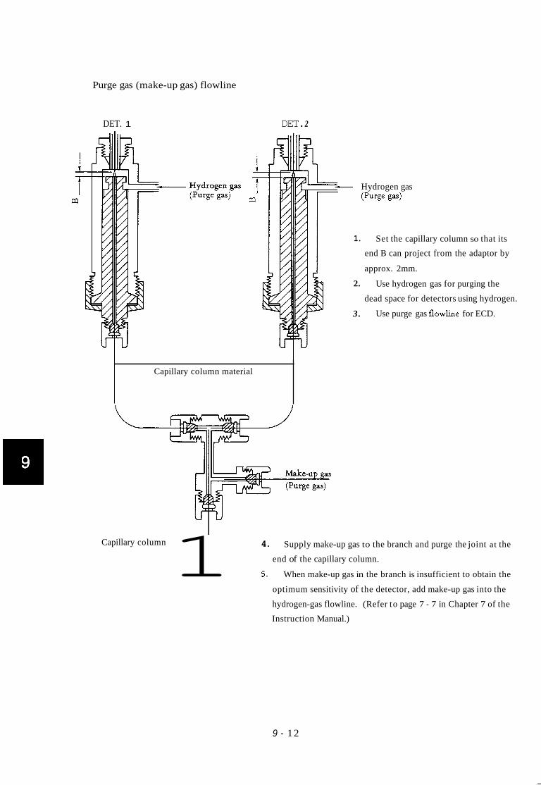
Purge gas (make-up gas) flowline
DET. 1 DET. 2
Hydrogen gas (Purge gas)
1. Set the capillary column so that its
end B can project from the adaptor by
approx. 2mm.
2. Use hydrogen gas for purging the
dead space for detectors using hydrogen.
3. Use purge gas f l o w h e for ECD.
Capillary column material
4. Supply make-up gas to the branch and purge the joint at the
end of the capillary column.
5. When make-up gas in the branch is insufficient to obtain the
optimum sensitivity of the detector, add make-up gas into the
hydrogen-gas flowline. (Refer to page 7 - 7 in Chapter 7 of the
Instruction Manual.)
1 Capillary column
9 - 12

221 -40010-10
10. Outline of Optional Units

1. Current Loop
Outline
The current loop (Option P/N 221-24200-93) or optical link inerface (221-42171-91) (In this case,
PC56N or PC57N is needed in chromatopac.) is designed to connect the Chromatopac (C-R2A (X), C-
R3A, C-R4A, C-RSA, C-R6A or C-R7A) to the GC-14B. Whereby, the GC-14B parameter list setting,
set value check and updating, measurement display, and others can be made by the Chromatopac, Other
functions can be added by utilizing the BASIC functions of the Chromatopac.
The detail of GC-14B key operation is outlined in Chap. 5 “Operation”, Para. 3.7.4 “List”.
Operation
1. Port opening
The port should be opened in the following steps before transmitting through the current loop.
Key in from the Chromatopac as stated below.
OPEN TRS MI 1 a 1 PortNo.
The port No. is determined by the dip switch of the current loop PCB (printed circuit board)
on the Chromatopac side. The port No. is generally 1. Another port No. may be set when two
or more current loops are used.
When the port is opened, the GC-14B displays “LINK OK” and sounds the buzzer. (If the port
has been opened previously, the GC-14B does not display or sound the buzzer.)
10- 1

2. Link device code (LDVC)
The link device code comprises two figures having the following meanings.
LDVC= 1 1 I 1 I ' I I l'sposition i t I I L - - l List is printed out by printer.
I
I I 10's position
L - 1 : Connected to channel 1 of the Chromatopac (start signal)
I
I I
2 : List is displayed on CRT.
I
2 : Connected to channel 2 of the Chromatopac (When channel 2 is available.)
Connected to both channels of the Chromatopac 3
For instance, LDVC = 11 means that the list is output by the printer and the channel 1 of the
Chromatopac is started up by pressing the 1-1 key of the GC-14B.
2.1 Link device code setting
Example: Setting LDVC to 11
(1) Setting from GC-14B
FILE -1 bl DisplayingLDVC
Setting 11
(2) Setting from Chromatopac
LDVC #1= _I 11
L- PortNo.
Ending communication with GC-14A
On the C-R7A, port opening and link device code setting can be made on the basic setting
menu. The details are given in the instruction manual of the C-R7A.
10 - 2

3. Check and updating of GC-14B settings and display of measurements by Chromatopac
3.1 Check of settings
(Example) Check of column initial temperature
PRINT CITP # 1 a _M_-
PortNo. L Control parameter of column initial temperature
The column initial temperature setting in the current file of the GC-14A is printed
out.
3.2 Updating of setting
(Example) Updating the injection port temperature setting to 200°C
INJT # l=200
I P o r t ~ o . _5_.
i Control parameter of injection port temperature
The injection port temperature parameter in the current file of the GC-14A is set
to 200°C
3.3 Display of measurements
(Example) Display of actual measured temperatures
PRINT DETT # l M L-UWCI h.-
L Standing for monitor
Port No.
Control parameter of detector temperature
The measured detector temperature is printed out.
Refer to Chapter 4 “Operation,” Sub-para. 2.3 “Control parameters.”
4. Port closing
A transmission error is caused if the power supply of either the GC-14B or the Chromatopac is
switched off with the current loop port opened. Close the port in the following manipulation
from the Chromatopac before switching off the power supply for preventing the error.
CLOSE u T R S u 1 - PortNo.
1 0 - 3

5. Instdation of current loop PCB
Remove the current loop PCB mounting plate on the gas chromatograph side and fasten the
PCB with two screws to the right side of the GC-14B proper as dlustrated. ~~ -
Connect the PCB to the GC-14B proper with the 60P cable inside the GC-14B.
10 -4

2. COSGC14A
Outline
The COS (card operation system) model GC-14B is a system comprised of the model GR5A
Chromatopac with a current loop.
All the conditions are automatically set by just inserting the IC card. The GC parameters of the
GC-14B and the analysis parameters of the C-R5A are automatically set. Manual setting is not
necessary and an error in manual setting is eh ina ted .
The system is suitable for carrying out several types of routine analysis.
COS-GC14B system
Components required for setting up COS-GC-14B
(1) GC-14B series gas chromatograph
(2) C-R5A Chromatopac
(3) Current loop for GC--l4B
P/N 221-02135-91
P/N 22 1 -24200-93
(4) IC card (with COS-GC program loaded) 10-card pack P/N 221-32522-91
l-card pack P/N 221-32522-01
1 0 - 5

3. Control of GG14B by Personal Computer Outline
The GC-14B series can be connected to a personal computer provided with an RS-232C interface (op-
tion P/N 221-27633-91). Whereby, it is possible to check and update the settings of the GC-14B and dis-
play measurements by the personal computer (as with the current loop outlined previously).
I. Specifications
Baud rate
Start bit 1 fixed
Stop bit
Bit length 8 fixed
Parity On-off selectable
Data type Character (ASCII)
110, 300, 600, 1200, and 2400 selectable
1 or 2 selectable
1 0 - 6

2. Setting of dip switches SW1 and SW2
SW1 Baud Rate Setting
1
2
3 4
5
6
1 1 0 3 0 0 6 0 0 1 2 0 0 2 4 0 0
0 0 0 0
0
- - - - - 0 ...... ON 0
0 ...... OFF - - 0 - -
0 - 0 - - - - - - - - - - -
SW2 Baud Rate, Stop Bit and Parity Setting
I ON I OFF ~~ ~~
1200 or 2400 baud
Parity off
Stop bit 1
~ ~~~ ~~
110,300 or 600 baud
Parity on
Stop bit 2
3. Installation of RS-232C PCB
Remove the mounting plate of the RS-232C PCB and install the PCB with two screws as Illust-
rated. Connect the PCB to the mGC-14B proper with the 60P cable (supplied with the GC-14B
proper).
The 232C cable connector on the PCB is a D-sub connector 25P socket type*. Purchase a cable
matching the connector. The cable is avdable also from us as stated below.
2 2 1-3346 0-05
221-33460-10
the connector on
1 0 - 7

4. Operation
Refer to the instruction manud of the persond computer for the details of operating procedure!
for port opening, baud rate setting, and others.
There are the following three control modes.
Parameter setting mode to GC
Parameter reading mode from GC
Measurement reading mode from GC
Prefix K, S , or M to the transmission command (shown in the next page) for specifying the
control mode.
K: Setting mode
S : Setting request mode
M: Measurement request mode
(Example) Setting column initid temperature to 100°C
K CITP 0100.00 -__I - L Lcaniagere tu rn
Only decimal point and figures 1,L Parameter reserved word
On receipt of the above message, the GC-14B answers ACK (acknowledged) or
NACK (not acknowledged) in a character string. After ascertaining the message from
the GC-l4B, proceed to the next step.
Setting mode
(Example) Displaying column initial temperature setting
I L Pumk:z:L:: Setting request mode
The GC-14A sends the data in 8 bytes and the computer receives and prints out the
8 bytes of data (INPUT$(8, #l)).
(Example) Displaying measured column temperature
L Carriage return Parameter reserved word
Measurement request mode
The GC-14B sends data in 8 bytes. The computer receives the 8 bytes (INPUT$
(8, #1)) and prints them out.
1 0 - 8

5. RS-232C GC Parameter Reserved Words
CITP AITM CITM INJT DETT AUXT AITM DlRG DlPL DlCR D2RG D2PL D2CR D3RG D3PL D3CR D4RG D4PL D4CR FILE TCDT EVNT
STTS DMAX CMAX AMAX RT CKSM STAR STOP CPR 1 CPR 2 CPR 3 CPR 4 CPR 5 CFP 1 CFP 2 CFP 3 CFP 4 CFP 5 CFM 1 CFM 2 CFM 3
CFM 4 CFM 5 APR 1 APR 2 APR 3 APR 4 APR 5 AFP 1 AFP 2 AFP 3 AFP 4 AFP 5 AFM 1 AFM 2 AFM 3 AFM 4 AFM 5 FLW 1 FLW 2 FLW 3 FLW 4
FLW 5 SNO STRK ISNO FSNO REPT WASH WSHT TWTE PROD I J l T IJ2T SLPT STRT SSTR SSTP
Refer to Para. 4 “Operation,” Sub-para. 2.3 “Control parameters” for the meanings of the
reserved words.
The words marked by “*”, however, are not shown in the description of the control
parame ten.
6. Example of a BASIC program for displaying measured GC-14B column, injection and detector
temperatures through the RS-232C port of a PC-9800 (NEC).
10 20 30 40 50 60 70 80 90
100 110 120
CLS LOCATE 10, 11 PRINT ’‘ COL. TEMP ” LOCATE 10, 12 : PRINT ‘‘ INJ. TEMP ” LOCATE 10, 13 PRINT ‘‘ DET. TEMP ” OPEN “COM N81NN” AS#1 FOR 1=1 T O 3 : READ A $ PRINT 81, A$ : C$=INPUT$(8, # l ) LOCATE 50, l o t 1 : PRINT C$ : NEXT RESTORE 120 GOT0 60 DATA ” MCITP ”, ‘‘ MINJT ”, ” MDETT ”
1 0 - 9
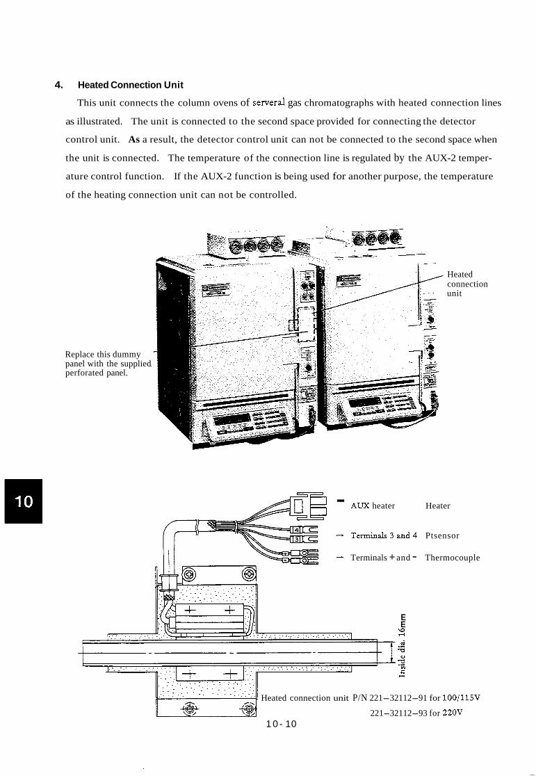
4. Heated Connection Unit
This unit connects the column ovens of serveral gas chromatographs with heated connection lines
as illustrated. The unit is connected to the second space provided for connecting the detector
control unit. As a result, the detector control unit can not be connected to the second space when
the unit is connected. The temperature of the connection line is regulated by the AUX-2 temper-
ature control function. If the AUX-2 function is being used for another purpose, the temperature
of the heating connection unit can not be controlled.
Replace this dummy panel with the supplied perforated panel.
Heated connection unit
- AUX heater Heater
- Termiuals3and4 Ptsensor
.-L Terminals + and - Thermocouple
E E
d
2
\o 4 -- *
Q)
v)
CI E
Heated connection unit P/N 221-32112-91 for 100/115V
221-32112-93 for 22OV 1 0 - 10

5. Add-on Unit Case
The add-on unit case is hung with a hook on the right side of the GC-14B as illustrated.
To add a detector control unit and an interface (PRG-14, AOC, etc.), the following extension bus
cables are required.
60P extension cable
40P extension cable
P/N 221-32374-91 (For adding interface)
P/N 221-32373-91 (For adding detector)
Add-on unit case, control unit P/N 221-32364-91
10 - 11

FIX the ground wire of add-on unit case to the rear panel of GC-14B as following figure.
Ground wire
\I n n
I
10 - 12
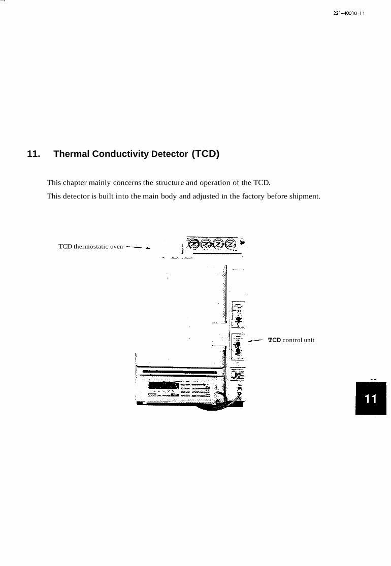
1
221-40010-1 1
11. Thermal Conductivity Detector (TCD)
This chapter mainly concerns the structure and operation of the TCD.
This detector is built into the main body and adjusted in the factory before shipment.
TCD thermostatic oven
TCD control unit

1. General Description
1.1 Principle of operation
When the metallic filaments heated with current flowing are present in a thermally conductive
carrier gas such as helium, the sample components with lower thermal conductivity than the
carrier gas raise the filament temperature when they pass through the carrier gas.
The chromatogram is obtained by measuring a change in the filament resistance caused by the
temperature rise.
1.2 Major system components
0 TCD thermostatic oven (100- 1 2 0 ~ )
1.3 Specifications
221-32743-91
The TCD for the GC-14B consists of the
@
units shown at left.
221-23821-9 1 TCD control unit (1 15v, 220v, 240V)
@
I TCD thermostatic oven (220-2240~) I 221-32745-93
221-23821-96 (230V)
Triac unit for thermal control 22 1-32896-96
@ Power transformer 221 -32253-91 (1 15V. 220V, 240V)
Standard attachments
SUS column adaptor
SUS column adaptor
Graphite ferrule (X 10)
Column joint parts
Reference flow h e piping
INJ side
DET side
PIN
221-14087-91
221-1 0079-91
221- 10076-91
22 1-1 0078-91
201-48560-70
Q'tY
2
2
1
2
1
Detector: Tungsten rhenium filaments (Approx. 10052 each at ambient temper-
ature) . 4element filament semi-diffusion differential flow line type.
Maximum temperature: 399°C
11 - 1

Power source:
Current:
Polarity selection:
Constant current control type
0 - 2-mA (In steps of 1mA)
(In He carrier gas, a positive peak appears when the sample is injected
to column 1 at POLARITY, INJl(+).)
Zero adjustment: COARSE and FINE
Built-in fdament protection circuit
Sensitivity: Approx. 6000mV.m!2/mg (Differs depending on the sample and operat-
ing conditions)
-1 These specifications are applicable to the unit built into the main body and adjusted
in the factory.
@ TCD cell
0 TCDheater looV 220v
@ Pt sensor
2. Structure
TCD Thermostatic Oven
4-element h e n t 20 1-40034 provided 221-32974-91 221-32974-93
221-06625-93
TCD cell @ is cased in the
thermally controlled aluminium block.
The inlet side of the TCD is connected
&om the lead pipe and column joint
@ to the column oven via the
detector thermostatic oven.
The outlet side is connected to the
the pipe @ on the left side of GC
main body.
0 ~ ~ l ~ ~ ~ j ~ ~ ~ FLOW 1 side 221-32577-91 FLOW 2 side 221-32577-92
8 I ventpip pipe ~ 221-13964-91 I
0
@
Washer 201-3021 1-02
Nut 201-46833
0 1 Spacer I 221-23552 I
11 - 2

7
TCD Control Unit
ON-OFF switch:' TCD ON-OFF switch
Zero adjustment: COARSE
Zero adjustment: FINE
On-base pilot lamp: Lights when the zero point lies within approx. klOmV of zero.
Overcurrent pilot lamp: Lights when the overcurrent protection circuit is actuated.
Polarity pilot lamp: A chromatogram at FLOW 1 side appears positive at INJl(+).
Connecting terminah: 1 - 4: TCD s igna l input
5, 6:
7, 8: Triac drive signal
Pt sensor for thermal control
Output connector
Main body connector (40P bus line)
TCD power connector
11 -3

Triac Unit for Thermal Control, Power Transformer
Triac unit for TCD thermal control
1 TCD transformer __ . - __
-I-;
@ Triac Assy for thermal control: P/N 221-32896-96
TCD thermostatic oven heater power control parts
TCD power transformer: P/N 221-32253-30 (for 230V) @ : P/N 221-32253-91 (for other power)
TCD control unit power transformer
11 -4

7
3. Mounting the TCD in the Main Body
The TCD is built into the main body before fatctory shipment. The mounting procedures shown
here will serve for maintenance.
3.1 Mounting the TCD thermostatic oven
% 47
. . . . . . . . 1 . . I . - I.
The TCD thermostatic oven is provided at the rear of the detector thermostatic oven at the
upper part of the column oven.
This detector delivers the chromatograph sgnal by sensing even a &ght temperature difference.
In mounting, the detector should be insulated with due care.
Mounting procedures
@ Remove the detector thermostatic oven cover and insulating material, and expose the
aluminum heating block. See @ in the m e .
@ Locate TCD thermostatic oven @(with the column connecting pipe supplied) at the
nght-hand side of the detector thermostatic oven at the upper stage of the oven case.
(To make this operation easier, remove the mounting base @ from the oven and attach it
to the rear panel.)
@ Fit the column joints@ into the detector block holes 0, and fix it with the sleeves,
washers and nuts from the column oven side.
@ Bring the piping close to the detector block, and clamp the block with the pipe clamp.
Then cover the block with aluminum foil (commercially available cooking foil), and charge
with the insulating materials.
1 1 -5

3.2 Mounting TCD control unit
M4 screw
- __ -_ The TCD control unit is contained in the control unit casing at the right of the oven.
Normally it is mounted in the 1st position.
Procedures
@ Remove the control unit front cover, side panel and rear cover. Insert the control unit form
your side and fx it at the upper and lower parts of the front panel with M4 screws and tooth
Washers.
- @ Connect 40P bus line. -
-1 If the power of the unit is turned ON without connecting the 4OP bus line,
control is disabled. An overcurzent may flow in the TCD cell.
@ Connect the lead coming from the power transformer.
@) Attach the terminals to the rear terminal strip.
*If the unit is mounted in the 2nd position, high sensitivity recording may be interfered with
by electromagnetic noise of the pulse motor at the column oven side. (Approx. 5pV of spike
noise appears in the record at TCD current of 200mA).
@ Mount the ground wire of the control unit to the rear panel as the fieme of 1 1-7.
1 1 - 6

1
3.3 Mounting TCD power transformer and triac assy for thermal control
The triac unit for TCD thermal control is mounted on the rear panel and TCD transformer on
the mounting base inside the rear panel.
TCD contrc unit
t 1 r
$ 4
‘ ~ ~ ~ t r a n s f o m e x
Layout of unit
11 - 7

4. Carrier Gas Flow Line
As the TCD is a density detector, the carrier gas flowing into the TCD should be maintained
constant. Temperature programmed analysis is done with the mass flow controller line.
Schematic drawing for flow line
In Single Flow Line
Injection port
I I
I I I
I
Carrier gas IN
Follow either of the methods 1 or 2 to establish the TCD reference flow line.
1. Establish the reference flow line by connecting the short-circuit pipe @ behind the pressure
regulator to the resistance column*. At this instance, set PI at least 5OkPa higher than the column
inlet pressure P2.
2. Connect the short-circuit @ to @ and make the reference flow line from @ utilizing
FID hydrogen pressure governor.
*A resistance tube charged with packing is available as an alternative resistance column. P/N 221-
3343 1-9 1
In Dud Flow Line or Dud Column
INJ n FID I
J
tl I CFC- 14PM [ Column 11
TCD
I t I 1 i j / /
IN J FID -
I I u 4 M I I I t // If
( / 1 T
- Carriergas
I I tl Colllmnl:l CFC- 14PM
In dual flow line or dual column, two units of the flow controller CFC-14M are used to establish
the complete dual flow line or dual column system.
11 - 8

5. Operation
5.1 Temperature setting
To set TCD thermostatic oven temperature, hit the 1-1 m] keys first, enter the
desired temperature, then hit the lml key. As the maximum operating temperature is fixed
at 399"C, the temperature cannot be set beyond this range. Be sure to set the temperature about
20 - 5OoC higher than the column oven temperature (final temperature in temperature elevation).
As shown in the schematic drawing, the TCD analytical unit controls the sample injection port
temperature and column-to-detector temperature separately. To set the sample injection port
temperature, hit the IINJ( key first, enter the desired temperature, then hit the Imj key.
To set the column-to-detector temperature, hit the -1 key first, enter the desired temperature,
thenhit the mi key.
5.2 Current setting
Current flowing in the TCD filaments is set from the keyboard. As the TCD is normally fixed
at DET No. 4, operate the keys in the sequence of m] [TI 101 m] . Kl (At this instance, the current setting is 1OOmA.)
CURRENT Current can be set from OmA to 1OOmA in
@ Carrier gaS He steps of 1mA. The upper limit of current
supplied to the TCD filament differs, as shown
in the figure at left, depending on the carrier gas
type an TCD thermostatic oven temperature
setting.
mA
200
100
I I I I
100 200 300 400 TCD TEMPOC
Sensitivity characteristics:
The detector sensitivity changes in proportion the cube of the current supply (CURRENT).
If the sensitivity is insufficient, increase the current value* in the range shown in the figure,
Note that an unnecessarily large current flowing into the detector may increase the filament
temperature and shorten the filament life, with resultant noise or drift.
*If the current setting is changed during analysis, the detector d be unstable for a while.
1 1 - 9
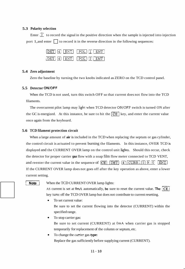
5.3 Polarity selection
Enter Kt to record the signal in the positive direction when the sample is injected into injection
port 1, and enter to record it in the reverse direction in the following sequences:
5.4 Zero adjustment
Zero the baseline by turning the two knobs indicated as ZERO on the TCD control panel.
5.5 Detector ON/OFF
When the TCD is not used, turn this switch OFF so that current does not flow into the TCD
filaments.
The overcurrent pilot lamp may lght when TCD detector ON/OFF switch is turned ON after
the GC is energized. At this instance, be sure t o hit the key, and enter the current value
once again from the keyboard.
5.6 TCD filament protection circuit
When a large amount of air is included in the TCD when replacing the septum or gas cylinder,
the control circuit is actuated to prevent burning the filaments. In this instance, OVER TCD is
displayed and the CURRENT OVER lamp on the control unit hghts. Should this occur, check
the detector for proper carrier gas flow with a soap film flow meter connected to TCD VENT,
and reenter the current value in the sequence of m] -1 (I1 10/ ml If the CURRENT OVER lamp does not goes off after the key operation as above, enter a lower
current setting.
v 1 When the TCD CURRENT OVER lamp lights:
AS current is set at O ~ A automatically, be sure to reset the current value. The
key turns off the TCD OVER lamp but does not contribute to current resetting.
To set current value:
Be sure to set the current flowing into the detector (CURRENT) within the
specified range.
To stop carrier gas:
Be sure to set current (CURRENT) at OmA when carrier gas is stopped
temporarily for replacement of the column or septum, etc.
To change the canier gas type:
Replace the gas sufficiently before supplying current (CURRENT).
11 - 10

6. TCD Troubleshooting
Trouble
1. Current does not flow.
Possible cause
a. T O control swicth OFF. b. CURRENT OVER lamp lit.
c. TCD filament burnt out.
d. TCD contrd unit fdty
a. Carrier gas does not flow. b. Gasleakage. c. Meter deflected beyond the full
d. Sensiti- too low. scale.
e. Sample adsorbed.
f. Data processor faulty.
a supply voltage fluctuates.
b. Data processor faulty.
c. Contact failure in the signal cable. d. Gas leakage. e. Detector contaminated. f. Piping contaminated. g. Column contaminated. h. Evaporator contaminated. i. Purity of carrier gas. j. Mass flow controuer (or pressure
k. Affected by the air-conditioner. 1. Flow control unit purged insuffici-
regulator) faulty.
ently. m. TCD cell defective. n. TCD c o d unit defective.
a Power source noise.
b. Data processor faulty.
c. Sensitivity too high.
e. Strong electromagnetic wave.
Check and correction
a. Turn the switch ON. b. Eliminate the cause and reset the
current value. c. Detach TCD lead from the termi-
nal and check it with atester.
6 Repair or rephe.
a. CheckTCD VENT. b. Run the gas leak test. c. Turn the zero adjustment.
d. Check the current value and sample quantity.
Check the analytical conditions.
check for faulty operation.
e. Conduct a repeat analysis.
f. Short-circuit the input signal and
a Checkwitbatesterandoscillo- scope.
b. Short-circuit the input signal and
c. Vibrate the signal cable. d. Run the gas leak test. e. Clean with solvent. f. Replace the piping. g. Replace or age the column. h. Clean with solvent. i Replace or attach the filter.
j. Replace the mass flow controller (or pressure regulator).
k. Stop the air conditioner. 1. Repeat purge.
check for faulty operation.
m. Replace. n. Repairorrepke.
a Change the power source or attach a p w e s Bter.
b. Short-circuit the input signal and check for faulty operation.
c. Check the current value and sample quantity.
e. Install GC- 14B at another place or remove the noise source.
11 - 11

Trouble
5 . Peak becomes broad.
5. Peak becomes sharp.
7. Peak tailing.
8. Abnormal peak appears.
Possible cause
f. TCD filament contaminated. g. The unit vibrates. h. Data processor interfered with by
electromagnetic waves.
i. TCDceIl defective.
a. Carrier gas flow low. b. Column temperature low. c. Dead volume present.
d. Column deteriorated. e. Erroneous selection of the column
(type or length).
low. f. Evaporator or detector temperature
a. Carrier gas flow high. b. Column temperature high. c. Column deteriorated. d. Erroneous selection of the column
(type or length).
a. Glass insert damaged. b. Excessive injection amount.
c. Erroneous selection of the column. d. Evaporator contaminated.
a. TCD cell defective. b. The previous peak appears.
c. Sample decomposed (changed).
d. Glass insert contaminated. e. Injection rubber plug pierced with
hole.
Check and correction
f. Purge or replace TCD cell.
g. Check the fan motor cushion. h. Keep away from a transceiver or
other oscillators.
a. Increase the flow. b. Increase the temperature. c. Check the column joint.
d. Replace or age the column. e. Replace the column.
f. Increase the temperature.
a. Reduce the flow. b. Reduce the temperature. c. Replace or age the column. d. Replace the column.
a. Replace. b. Check the current value and
injection amount. c. Replace the column. d. Clean with solvent.
a. Replace TCD cell. b. Age the column
c. Check the analytical conditions and sample storage method.
d. Clean the insert and evaporator. e. Replace.
11 - 12

221-40010-12
12. Hydrogen Flame Ionization Detector (FID)
This chapter mainly concerns the structure and operation of the FID.
This detector is built into the main body at the factory or at the installation site.

1. General Description
1.1 Principle of operation
When organic compounds are burnt in the hydrogen flame, ions are produced in the flame.
The electrode with DC voltage applied traps these ions whose current is measured with the
electrometer.
1.2 Major system components
The FID for the GC-14B consists of the following units.
n
C n controller
L
- -
Air Hydrogen
A
II I I I I
I I I I
I
I I I I I
A: FID control unit (Electrometer) P/N 221-23820-96 (for 230V)
PIN 221-23820-92 (for 115V, 220V, 240V)
B: FIDcell P/N 221-32361-91 (including mounting parts)
C: HVcord P/N 221-23710-94
Note I FID control unit A’ is required to control FID cell signals B and By independently.
To measure the difference in the signals B and B’ of the FID cell, connect B and B’
signal cables to FID control unit A.
Standard accessaries
Ignitor P/N 670- 12584 1
Battery SUM-2 P/N 074-70010 1
Sus column adaptor DET 1 (2 peaces for Dual)
1 2 - 1

1.3 Specifications
FID cell . Sample injection port evaporator: . FID (Hydrogen flame ionization detector)
Glass insert type/on-column type
Collector electrode: Cylindrical type
Electrode applied voltage: k200V
Dynamic range: 10'
Minimum detecting amount: 3 X 10-12g/sec (sample: diphenyl)
Maximum operating temperature: 400°C
Ignitor:
Nozzle: Quartz
Filament externally attached, common to both flow lines
Electrometer
Range: i o o , i o l , 102,103
Polarity selection: INJl (+), INJ2(+)
Coarse zero adjustment:
ON BASE lamp:
Maximum sensitivity:
Linearity: l o 5 min
Noise:
Background compensation: NORM position -+8 X 10-"A
k6.4 X 10-IOA
-+ 1 OmV
1 X 10-I2A/mV (fun scale)
1% or less at maximum sensitivity
EXT position k80% of attenuation 1024 irrelevant
of the range
0 Setting with key operation:
Setting with electrometer:
Range, polarity selection
Coarse zero adjustment, ON/OFF switch
OFF mode does not allow key entries and maintains
the setting before the switch was turned OFF.
0 FID ON/OFF switch:
1 2 - 2
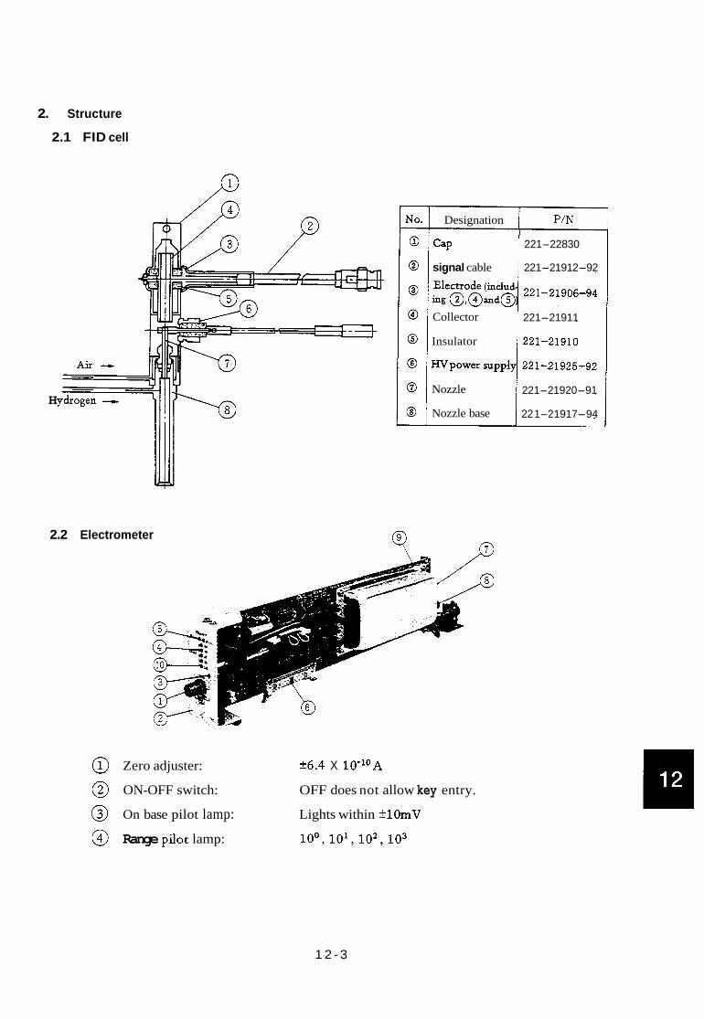
2. Structure
2.1 FID cell
H
i
Designation PIN I
221-22830 Cap
signal cable 221-21912-92
221-21911
221-21910
221-21920-91
22 1-2 1917-94
Collector
Insulator
Nozzle
Nozzle base
2.2 Electrometer
@) Zero adjuster: k6.4 X 10-l0A
@ ON-OFF switch: OFF does not allow key entry.
@ On base pilot lamp: Lights within *lOmV
@ Range pilot lamp: io0,io1,io2,103
1 2 - 3

@ Polarity pilot lamp: INJ(+) ..... Positive peak appears when the sample is
injected to 1.
INJ(-) ..... Positive peak appears when the sample is
injected to 2.
@ 40P bus cord connector: Control signal
@ Signalinlet: Connected to FID cell collector
@ HVoutput:
@ @ SATLAMP: Light more than 1 V output
Connected to FID voltage electrode via FID and HV cord
Backing mode selector switch: t NORM 4 EXT
Parts Designation
7276M 1OOK
KSD I-2-0-LL-DC
LED GL3PR2
LED 3HY2
SW slide
Reed relay
~
sw1
Parts No.
054-22850
064-50641-13
061-78037-07
061-78039-02
064-16035-02
065-63426-02
Remarks
For zero adjustment
For ON-OFF SW
For pilot lamp (red)
For pilot lamp (yellow)
For backing mode selection
For range selection
1 2 - 4

3. Mounting FID in Main Body FID cell mounting
Fit the hexagonal section of PID cell to the hexagonal holeinthecolumn oven roof.
I
Mounting procedures
1) Remove the detector thermostatic oven
cover and insulating material, fit insulation Sleeve 0, then'insert FID cell &om the top.
~ i x the c e ~ by amaching Sleeve 0, washer
@ and nut @ fiom the column oven side.
Let the hydrogen and air pipes through the
notch of insulation sleeve @ and lead them
out of the oven rear.
2 )
3)
4) Detach Hv electrode from the detector
heating block and charge the block with the
insulating material.
5) Chargetheinsulatingmad Atthis
instance, blow out any dust ifFID electrode
mounting parts are seen as dusty. 6 ) Attach the electrode.
1x1 If the FID is mounted in the
second hole from the left side of
the detector block and mtedaced
with the TCD, replace insulation
sleeve @ with P/N 221-32978 far TCD. (Standard attachment of
TCD oven)
- column oven -
12- 5

Mounting parts
@ Insulation sleeve P/N 221-22542 @ Nut P/N 22146833
@ Sleeve P/N 221-23552 @ a c a p P/N 221-22830
@ Wder P/N 201-30211-02 @ Protector P/N 221-32362
Mounting FID control unit
4oPilatcable
Mounting procedures
1) Remoie the front cover, side panel and mar cover from the electric control unit at right of the
oven. Insert FID control unit from your side, and fix it at the upper and lower parts of the front panel
with M4screws andtooth washers.
2) 3) Insert 40P flat cable.
4)
Attach the p u u d wire of FID umml uuit @em line with the tuminal at the ad) to therearpaneL
Connect FID signal input cable (one cable when FID is used singly) with Hv cord.
HV cord ends are branched into 1 and 2. When FID signal input cable is attached to 1,
a peak appears in the positive direction with the polarity selection of POL( 1). m 12-6

4. Operation
4.1 FID control unit
(1) Range (RANGE) setting
Select the electrometer sensitivity from the keyboard.
Magnify the peak in steps of 10 times. The sensitivity becomes lower in the sequence of
1 -+ 10 -+ l o 2 4 lo3 . Enter numericals of the exponent part from the key board
For instance, to set the range at 10 when FID is connected to DET No. 1, enter the keys in the
sequence of [=I ffl W l m 111 mJ . To set the range at 1, key in 0.
Once DETl is set, FID remains at DETl until DET No. is changed. If -1 m are keyed to change the range or polarity without operating m] [ENTI . FID range is
switched to lo3. The setting is displayed on the detector control panel. To display it on the
keyboard panel, hit [m] key
Sat lamp lights when the F’ID signal output is +1V or higher. Output signal at this time is
around +1V. In this case, quantitation is not available. If quantitation is required, take
appropriate measures such as diluting the sample or changing the split ratio.
(2) Polarity setting
Select the polarity from the keyboard. The signal from the column 1 appears positive at the
recorder terminal output with 1 entered, while the signal from column 2 appears positive with
2 entered.
For instance, with [=I m] (not required when DETl was already selected)
/II w] keyed, the signal from the column 1 appears positive at the recorder output.
The setting is displayed by the lamp on FID control panel. INJl(+) lamp being lit means that
the signal from column 1 is positive. To display the setting on the keyboard panel, enter
( 3 ) Backing mode selection
The backing mode selector switch is mounted on the PC board of the FID control unit.
If FID background value is so large that zero adjustment is impossible simply by turning the
zero adjusting volume, set the backing mode selector switch at “EXT” to examine the degree
of unbalance. At this instance, the output signal becomes too large due to insufficient aging
of the column or flow line contamination.
1 2 - 7

4.2 Hydrogen and air flow setting
The detector sensitivity differs depending on the mixing ratio of carrier gas (nitrogen), hydrogen
and air. The optimum mixing ratio is required to maximize the sensitivity.
1.5-
x
-2 2 -5 m E: 0 0.5 1.0- 1 -
1.5-
4.l Hz 50ml/min
NZ 6Oml/n11n .2, .- c) .- ; 1.0
Nz 2h:r 60ml/min v) 0.5 Air 500ml/min
( , , , . , , , , , I
0 20 30 40 50 60 70 80 90 100 0 200 500 1000 - H2 flow ( d / m h ) - Air flow (mQ/mh)
Mixing ratio of nitrogen and hydrogen, and sensitivity
Air flow and sensitivity
In the 3mm-inner dia. column, set the flows as follows.
Carrier gas (nitrogen) 60mPlmin (40 - 60mP/min)
Hydrogen* SOmPlmin (30 - 60mP/min)
Air 500mP/min (400 - 600mP/min)
*Do not increase the hydrogen pressure beyond 1OOkPa.
The hydrogen and air flows are controlled with pressure regulators. The pressure - flow
calibration curve shown in the figure below is useful in setting the flows from the pressure
readings.
mUmin lo00
0 20 40 60 8 6 100 kPa Air pressure vs Flow rate
mumin The araDh shows the twical curve. - . .. I I I I I
0 20 40 60 80 100 kpa
Hydrogen pressure vs Flow rate
1 2 - 8

4.3 Flow measurement
FID hydrogen and air flows are measured at the flow controller H, OUT or AIR OUT joint.
H2 or AIR OUTjoht II / Resistance tube
Flowcontroller JJJ /
Remove FID cell lead pipe and attach the flow meter (option) to measure the flows.
4.4 FID ignition
The FID does not ignite at the mixing ratio of hydrogen and air preset for analysis. To ignite,
reduce the air flow. After ignition, return the flow to the specified value.
When the lighter is brought near the FID outlet cap as shown in the figure, push the button.
Note 1 The lighter generates noises when igniting.
During ignition, do not bring the lighter into contact with the FID outlet cap or collector outlet. Keep distance of about 5mm. Also, do not use the lighter during
analysis.
I I If the R D cannot be easily ignited, remove the cap and ignite.
1 2 - 9

4.5 Reduction of air flow
With IGNIT button of the flow controller depressed, the leak valve opens to reduce FID
auxiliary combustion air flow, thereby making the FID ready for ignition. At this instance, ignite
FID with the lighter as mentioned above.
After ignition, release IGNIT button so that the air is fed into FID cell at the flow preset with
the pressure regulator.
4.6 Confirmation of ignition
A slight “pop” is heard upon ignition. The FID is ignited if moisture (vapors produced by
hydrogen combustion) are deposited on a mirror or lustrous metallic surface that is brought close
to the FID cell exhaust hole.
4.7 Nozzle cleaning If ??ID is not ignited smoothly or a peak is not detected, the FID nozzle should be cleaned.
First turn off the power of the system and remove the FID collector. Insert a thin stick into
the nozzle and clean inside.
<Option> Wire for cleaning FTD nozzle (P/N 221-24165-91) is convenient.
1 2 - 10

5. FID Troubleshooting
I Trouble
1. FID does not ignite. Flame goes off.
Possible cause
a. Carrier gas, H and Air flows im- proper.
b. Detector temperature low. c. Nozzle clogging. d. Air leak valve defective. e. H2 flow line clogging.
a. Flame goes off. - b. HV not applied to the nozzle end. c. Gas leakage. d. Meter deflected beyond the full
scale of -. e. Sensiti~ty too low.
f. Sample adsorbed.
g. Data processor faulty.
a. Supply voltage fluctuates.
b. Contact failure in the signal cable. c. Gasleakage. d. Detector contaminated. e. Piping contaminated. f. Column contaminated. g. Sample evaporator contaminated. h. Purity of carrier gas. i. Mass flow controller (pressure
remulator) defective. "
j. i?ID control unit defective.
a. Powernoise.
b. Zero adjusting volume defective. c. Nozzle contaminated. ~ ~ ~~~ ~
d. FLD control unit defective. e. Data processor faulty.
f. Contact failure in FID signal cable. g. Air supply silica gel deteriorated. h. Strong electro-magnetic wave
a. Carrier gas flow low. b. Column temperature low. c. Dead volume present.
Check and correction
a. Check the flows with the flow meter.
b. Increase the temperature. c. Clean or replace. d. Check for proper operation. e. Replace.
a. Re-ignite. b. Check with the tester. c. Run the gas leak test. d. Check by turning the zero adjust-
ing volume. e. Check RANGE and sample
quantity. f. Conduct repeated analysis.
g. Short-circuit the input signal and Check the analytical conditions.
check for proper operation.
a. Check with a tester or osciIlo- scope.
b. Vibrate the signal cable. c. Run the gas leak test. d. Dismantle and clean. e. Replace. f. Replace or age the column. g. Clean with solvent. h. Replace or attach the filter. i. Replace.
j. Repairorrepbce..
a. Change the power source or
b. Replace. attach a power &ez
c. Dismantle and clean. d. Repair or replace. e. Short-circuit the input s igna l and
f. Dismantle and clean. g. Replace. h. Install GC-14B at another place
check for proper operation.
or remove the noise source.
a. Increase the flow. b. Increase the temperature. c. Check the column joint.
12- 11

Trouble
6 . Peak becomes sharp.
7. Peak tailing.
8. Abnormal peak appears.
Possible cause
d. Column deteriorated. e. Erroneous selection of the column
(type or length).
temperature low. f. Sample evaporator or detector
a. Carrier gas flow high. b. Column temperature high. c. Column deteriorated. d. Erroneous selection of the column
(type or length).
a. Glass insert damaged. b. Excessive injection amount.
c. Erroneous selection of the column. d. Sample evaporator contaminated.
a. Ghost appearing from the injection
b. Sample decompsed (or changed). septum.
c. The previous peak appears. d. Glass insert contaminated.
e. Injection septum pierced with a hole.
Check and correction
d. Replace or age the column. e. Replace the column.
f. Increase the temperature.
a. Reduce the flow. b. Reduce the temperature. c. Replace or age the column. d. Replace the column.
a. Replace. b. Check RANGE and injection
c. Replace the column. d. Clean with solvent.
amount.
a. Age the septum.
b. Check the analytical conditions and sample preparation method.
c. Age the column. d. Clean the insert and sample evapo-
rator. e. Replace.
12 - 12

SHIMADZU CORPORATION 63 SHIMAOZU CORPORATION. lntamtioaal Markation Division 3. Kanda-Nishikicho 1-chome. Chiyoda-ku. Tokyo 101. Japan
Phone:81(3)3219-5641 F a x 81 (3)32l9-5710 Cable Add.:SHIMAOZU TOKYO Overseas Telex No.:0232-329 ISHMDT J) SHIMADZU SCIENTIFIC INSTRUMENTS. I I C . 7102. Riverwood Drive. Columbia. Maryland 21046. USA. Phone:l(410)381-1227 Fax. 1 (410)3m-1222 Toll Free: 1 (800)477-1227
SHIMAOZU EUROPA 6mbH AlbeR-Hahn-Strase 6-10. D- 47269 Duisburg 29. F.R. Germany
Phone 49 (203)7687-0 Fax. 49(203)766625
SHIMADZU (ASIA PACIFIC) PTE 110. 16 Science Park Drive z 01 -01 Singapore Science Park Singapore 0511 Republic of Singapore
Phone 65-778 6280 Fax.65-779 2935
SHIMADZU OCEANIA PTY. LTD. Unit 5 7 Srubbs Street Auburn N S W 2144 Australia
Phone 61 (2)748-3233 Fax.61(2)748-3172
1995. I2 3500-I2500-155TD (A-742)