gas electron multiplier technology for digital hadron calorimetry fermilab, september 2005 andy...
TRANSCRIPT
Gas Electron Multiplier Technology
for
Digital Hadron CalorimetryFermilab, September 2005
Andy White
(for the GEM-DHCAL group:
UTA, U.Washington, Tsinghua U. )

OVERVIEW
- Goals of GEM-DHCAL program
- Brief statement of DHCAL requirements
- GEM-DHCAL design concept
- GEM – basics of foils, stability,…
- UTA GEM prototypes
- Results on crosstalk, multiplicity
- Signal sizes
- Medium scale prototype plans
- 1m3 stack plansNote: Simulation, PFA, ASIC, test beam trigger/timing NOT discussed.
Goals of DHCAL/GEM Project
Design and construct a Linear Collider Detector calorimeter system based on GEM technology. Build/study GEM systems (in process)
Define operational characteristics of GEM system (in process)
Understand DHCAL/GEM systems in terms of proposed LC detector design concepts (in process)
Construct full size test beam module and beam test (planning)
Use test beam results to develop PFA for GEM-based DHCAL (started)
Develop full DHCAL/GEM calorimeter system design.
Digital Hadron Calorimetry
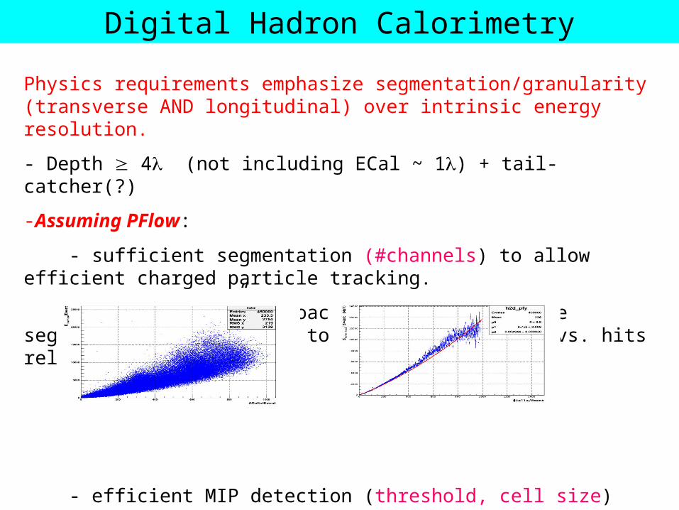
Physics requirements emphasize segmentation/granularity (transverse AND longitudinal) over intrinsic energy resolution.
- Depth 4 (not including ECal ~ 1) + tail-catcher(?)
-Assuming PFlow:
- sufficient segmentation (#channels) to allow efficient charged particle tracking.
- for “digital” approach – sufficiently fine segmentation (#channels) to give linear energy vs. hits relation
- efficient MIP detection (threshold, cell size)
- intrinsic, single (neutral) hadron energy resolution must not degrade jet energy resolution.
Digital Hadron Calorimetry
- A hit should be a hit -> keep multiplicity/crosstalk low to aid in pattern recognition/PFA
- Comparable granularity to the ECal – continuous tracking of charged particles.
- Provide efficient muon tracking through the calorimeter.
- Long term stable operation .
- Minimal module boundaries/dead areas.
- Stable technology – little/no access to active layers(?)

Why GEM ?
- Operates at modest voltages ~400V/GEM
- Fast (if needed) – electron collection, not ion drift.
- A lot of parallel GEM development for LC/TPC systems and other experiments (e.g. T2K)
- Shares ASIC development with RPC.
- A flexible technology with easy segmentation to well below the cell size needed for digital hadron calorimetry
- An alternative to RPC, Scintillator
- Works well with simple gas mixture (Ar/CO2)
- Demonstrated stability against aging
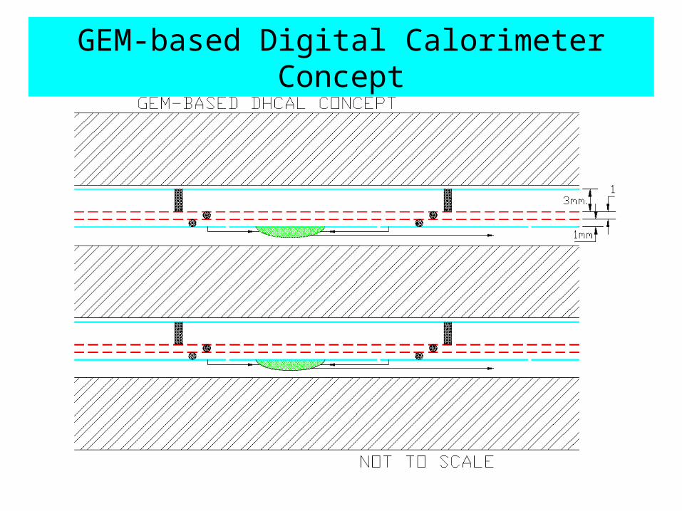
GEM-based Digital Calorimeter Concept
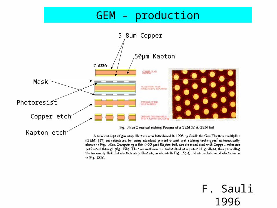
GEM – production
F. Sauli 1996
5-8µm Copper
50µm Kapton
Mask
Photoresist
Copper etch
Kapton etch

GEM – production
70m
140mCopper edges
Hole profile
Exposed kapton
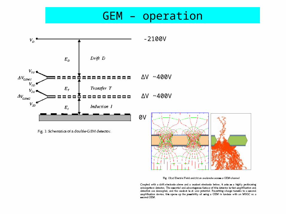
GEM – operation
-2100V
∆V ~400V
∆V ~400V
0V


COMPASS – triple GEM, CERN-made foils

GEM – aging
~1012 part/mm2

UTA GEM-based Digital Calorimeter
Prototype
UTA GEM - initial prototype

Anode pad
layout
1x2 cm2 pad
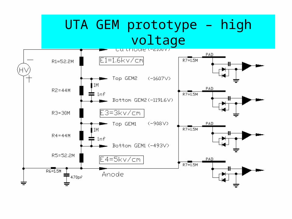
UTA GEM prototype – high voltage


Single cosmic event: upper = trigger,
lower = preamp output
UTA GEM Calorimeter prototype

(First!) GEM cosmic signal distribution with Landau fit

Landau Distribution from Cs137 Source
Signal Amplitude (mV)
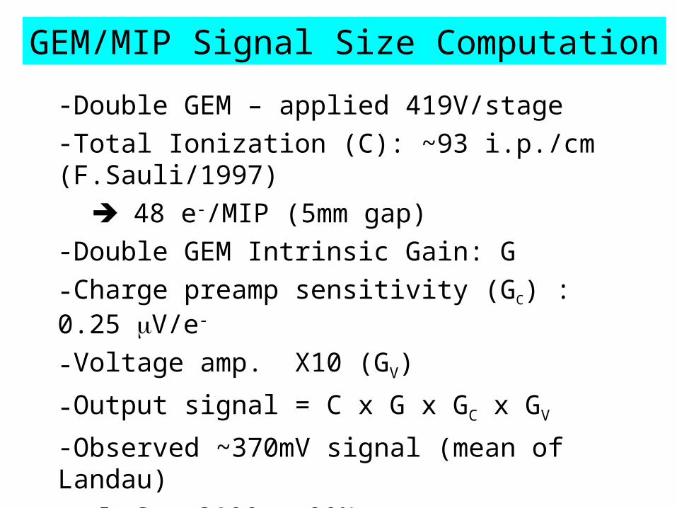
GEM/MIP Signal Size Computation
-Double GEM – applied 419V/stage -Total Ionization (C): ~93 i.p./cm (F.Sauli/1997)
48 e-/MIP (5mm gap)-Double GEM Intrinsic Gain: G-Charge preamp sensitivity (GC) : 0.25 V/e-
-Voltage amp. X10 (GV)
-Output signal = C x G x GC x GV
-Observed ~370mV signal (mean of Landau) G = 3100 ± 20%

CERN GDD group measurements
Measured UTA GEM Gain
UTA Prototype

Experience using GEM foils
- We have used the small (10cm x 10cm) framed GEM foils from CERN/GDD, and are starting to use the 30cm x 30cm foils from 3M Corporation.
- Started out in a Class 1000 clean room – for first prototype assembly.
- Later experience showed that foils can be “handled” carefully in normal lab. environment.
- We have assembled/disassembled our prototypes many times – they always work when you turn them on!
- Typical current ~few nA
- We provoked discharges and examined foils – damage found in few holes limited area – fixed by drop of acid.

0
100
200
300
400
500
600
700
800
900
1000
300 310 320 330 340 350 360 370 380 390 400 410 420 430
GEM signal levels for various gas mixtures

Nine Cell GEM Prototype Readout
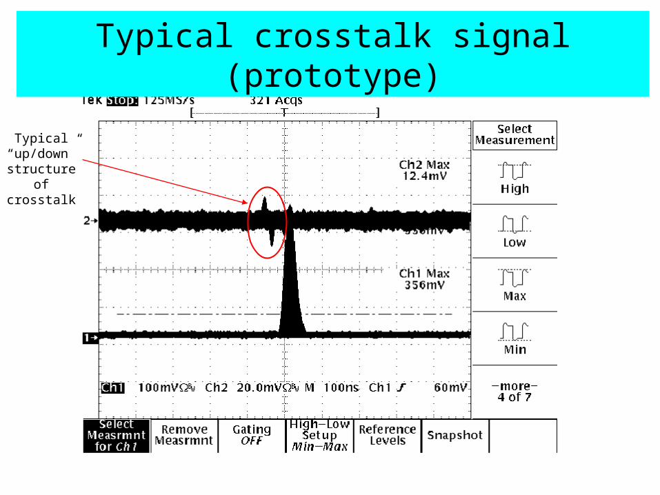
Typical crosstalk signal (prototype)
Typical “up/down” structure
of crosstalk
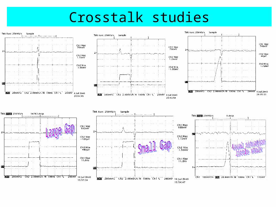
Crosstalk studies
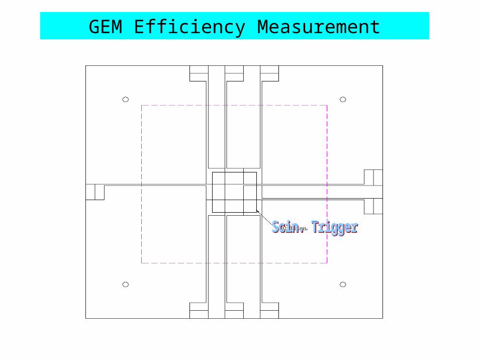
GEM Efficiency Measurement

Setup for 9-pad GEM efficiency measurement
3rd counter added

78
80
82
84
86
88
90
92
94
96
0 5 10 15 20 25 30 35 40 45
Efficiency of the 9-pads GEM chamber:
Ar:Co2=80:20V=409v
Two fold
Three fold
Three foldwith 3' separation
Threshold mv.
%
Eff. = 94.6%
after ensuring that cosmics must hit a pad
GEM efficiency measurement using cosmic rays

GEM/DHCAL MIP Efficiency - simulation
95%
Energy Deposited (MeV)
Eff
icie
ncy
Energy Deposit
MIP Efficiency

GEM Multiplicity Measurement
- 9-pad (3x3) GEM Chamber – double GEM
- Ar/CO2 80:20
- HV = 409V across each GEM foil
- Threshold 40mV -> 95% efficiency
- Sr-90 source/scintillator trigger
-> Result: Average multiplicity = 1.27

GEM/DHCAL signal sizes
Goal: Estimate the minimum, average and maximum signal sizes for a cell in a GEM-based digital hadron calorimeter.
Method: Associate the average total energy loss of the Landau distribution with the total number of electrons released in the drift region of the GEM cell.

Ionization in the GEM drift region
A charged particle crossing the drift region will have a discrete number of “primary” ionizing collisions (ref. F.Sauli, CERN 77-09, 1977).
An ejected electron can have sufficient energy to produce more ionization. The sum of the two contributions is referred to as the “total ionization”. In general,
nT = nP * 2.5
Using Sauli’s table, we calculate nT = 93.4 ion pair/cm for Ar/CO2 80/20 mixture.

Characteristics of the Landau energy loss distribution
The Landau distribution is defined in terms of the normalized deviation from the “most probable energy loss”, which is associated with the peak of the distribution – see the following slide.
The average total energy loss occurs at about 50% of the peak (on the upper side). This is the point we associate with the quantity nT.
In order to set a value for the minimum signal, we need to chose a point on the low side of the peak corresponding to a certain expected efficiency. From our GEM simulation, we find that we expect a 95% efficiency with a threshold at ~40% of the peak value – result from simulation (J.Yu, V.Kaushik, UTA)
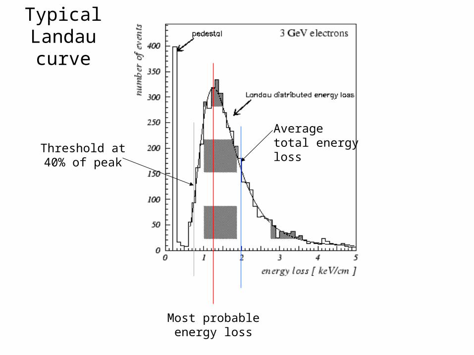
Most probable energy loss
Average total energy lossThreshold at
40% of peak
Typical Landau curve

GEM/DHCAL MIP Efficiency - simulation
95%
Energy Deposited (MeV)
Eff
icie
ncy
Energy Deposit
MIP Efficiency

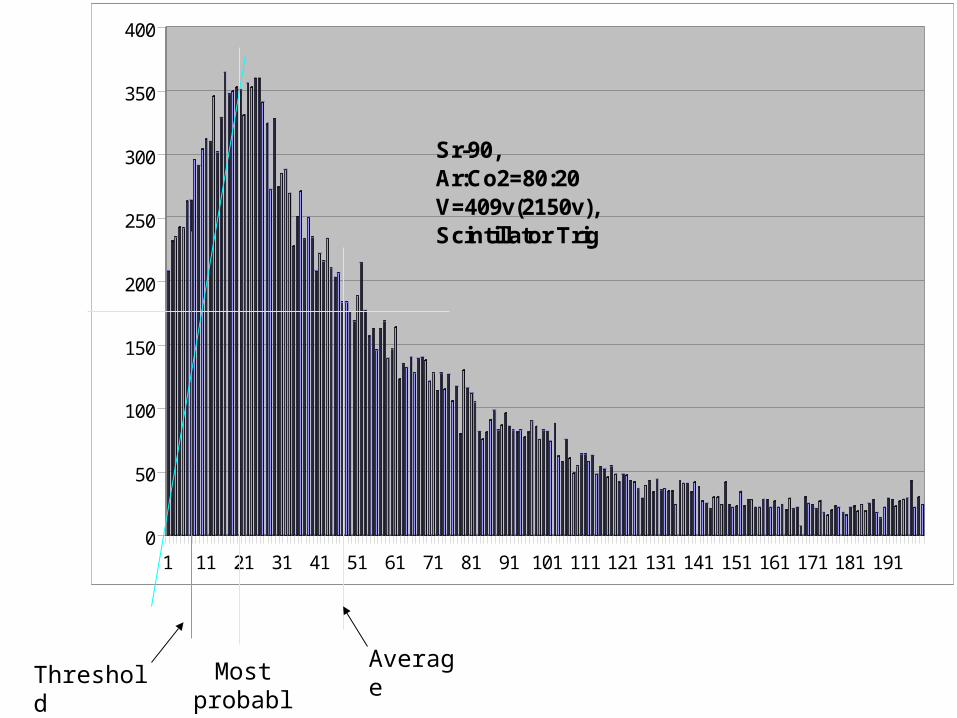
Calculating our GEM signal levels
Looking at the following slide for Ar/CO2 80/20 we see that the average total energy loss occurs at a signal size that is ~5x that for a minimum signal at 40% of the peak height on the low side of the peak.
So then, if nT = 93.4 ion pair/cm, then we expect ~28 total electrons on the average per MIP at normal incidence on our 3mm drift region. This gives 5.6 electrons for the minimum signal.
The gain we measured for our 70/30 mixture was ~3500, and we see a factor x3 for 80/20 (see following plot). Putting this all together, we expect
Minimum signal size = 5.6 x 3,500 x 3 x 1.6 x 10-19
= 10 fC
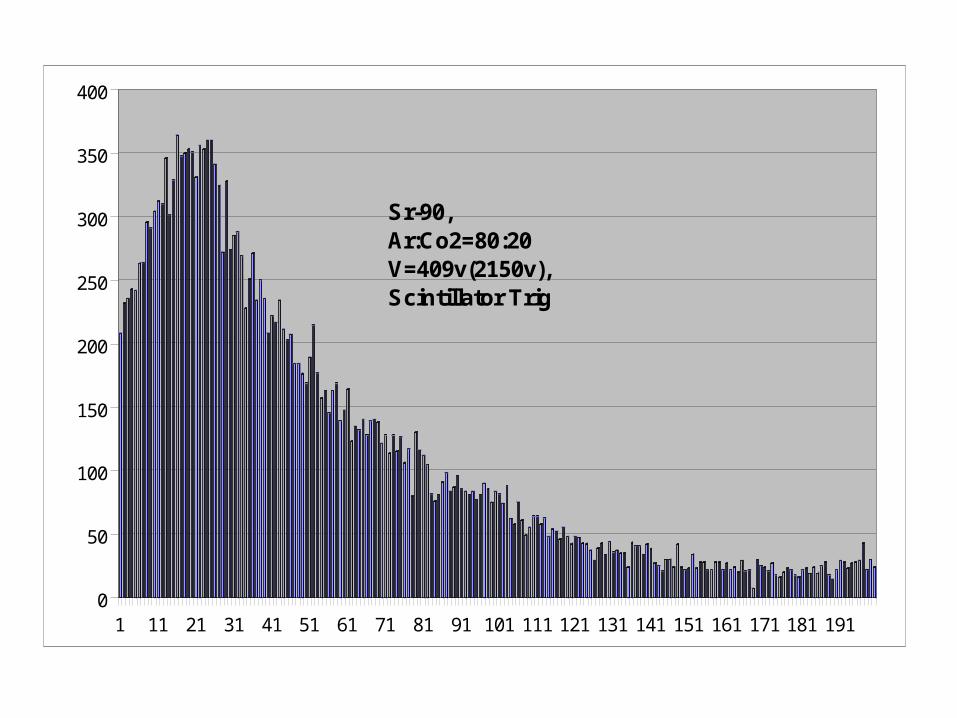
0
50
100
150
200
250
300
350
400
1 11 21 31 41 51 61 71 81 91 101 111 121 131 141 151 161 171 181 191
Sr-90,Ar:Co2=80:20V=409v(2150v),Scintillator Trig
Most probabl
e
AverageThreshol
d

0
100
200
300
400
500
600
700
800
900
1000
300 310 320 330 340 350 360 370 380 390 400 410 420 430
~ factor of 3 increase in signal at same voltage for 80:20 vs 70:30

Calculating our GEM signal levels
We also expect:
Most probable signal size ~20 fC
Average signal size ~50fC
These estimates are essential input to the circuit designers for the RPC/GEM ASIC front-end readout.
The estimate of the maximum signal size requires input from physics (+background(s)) simulation…

Plans for next GEM assemblies
- Produce and use larger GEM foils.
- Intermediate step towards full-size foils for test beam.
- Present 3M process allows ~30cm x 30cm foil production – etch window
- 30 foils ordered/ ~80 produced/being evaluated.
- Assemble 5 layers of DGEM chambers – Fall 2005.

Fermilab beam chamber
Fermilab beam chamber
DGEM
DGEM
DGEM
DGEM
DGEM
Cosmic stack using Double GEM counters
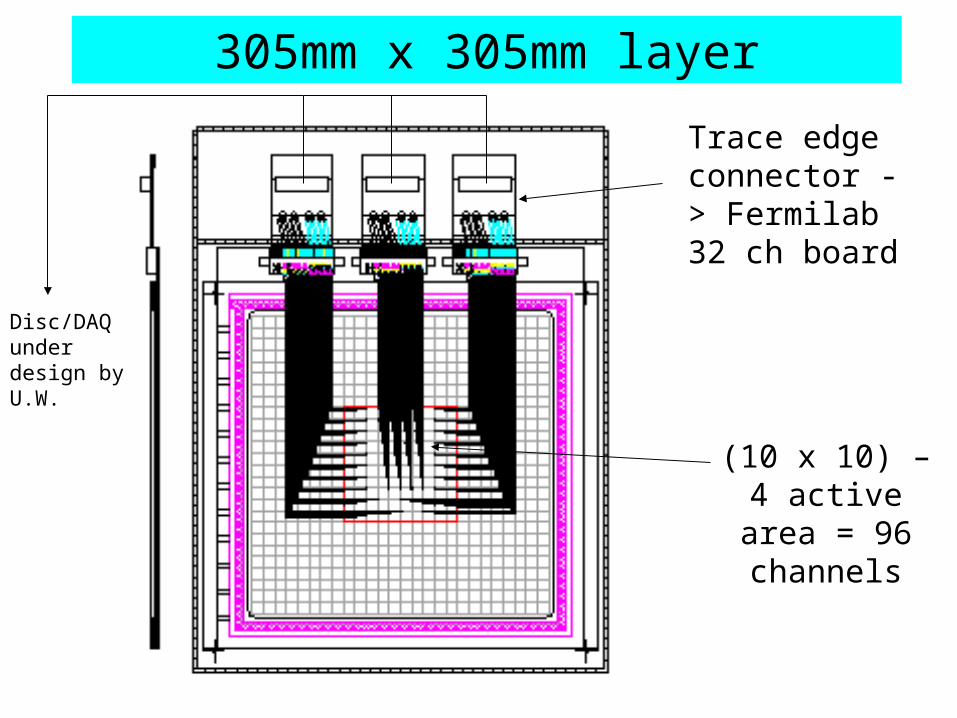
(10 x 10) – 4 active area = 96 channels
Trace edge connector -> Fermilab 32 ch board
305mm x 305mm layer
Disc/DAQ under design by U.W.

Cosmic stack using Double GEM counters
- Single cosmic tracks.
- Hit multiplicity (vs. simulation)
- Signal sharing between pads (e.g. vs. angle)
- Efficiencies of single DGEM counters
- Effects of layer separators
- Operational experience with ~500 channel system
- Possible test-bed for ASIC when available – rebuild one or more DGEM chambers.
- Proposal submitted to Korean Nuclear Laboratory for beam tests for 500-channel prototype.
T2K large GEM foil design
Institutes cooperating on foil production:
- U. Victoria BC (Canada) (T2K and LC TPC)
- U. Washington (DHCAL)
- Louisiana Tech. U. (LC TPC)
- Tsinghua U. (DHCAL)
- IHEP Beijing (GEM development)
- U. Texas Arlington (DHCAL)
(share cost of masks, economy of scale in foil production)

T2K large GEM foil design
(Close to COMPASS(CERN) foil design)
Dean Karlen, U.Victoria BC

3M GEM foil design
HV tabs to be longer

3M – gap between HV sectors
Guaranteed gap = 135µm

First 30cm x 30cm 3M GEM foils

First 30cm x 30cm 3M GEM foils
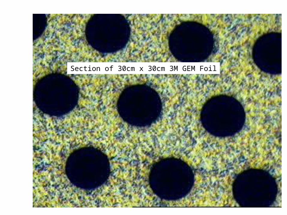
Section of 30cm x 30cm 3M GEM Foil


A piece of fiber inside the hole on uncoated GEM

A piece of fiber inside the hole on uncoated GEM

Something on the top surface
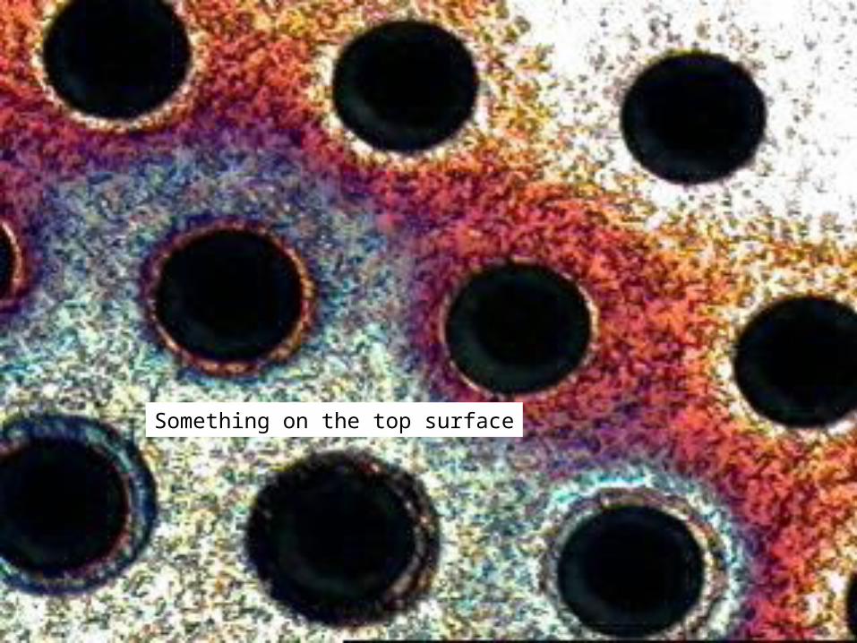
Something on the top surface

A “bad” hole on the coated foil?
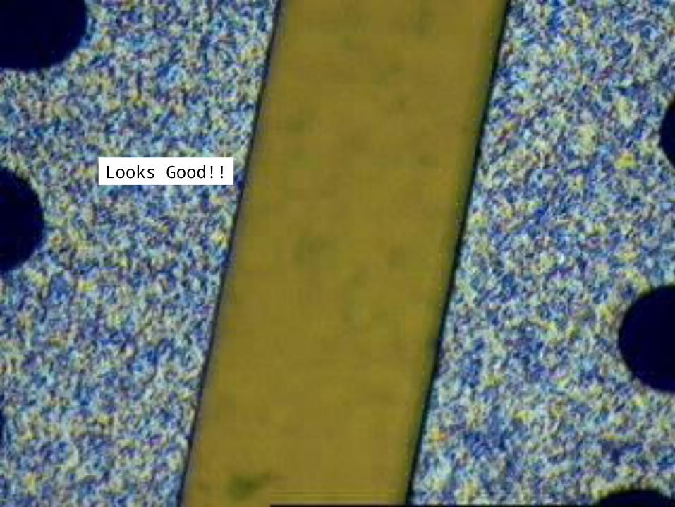
Looks Good!!


GEM foil costs
- CERN 10cm x 10cm, framed $400 each
- 3M 30cm x 30cm foils
- in small quantities ~$600 each
- for 1m3 stack (720 needed) ~$150 each
- for final calorimeter (80,000) $?? Each
- goal ~$1,000/m2 (foils ~5% of HCal cost)
Other potential sources of foils
- Other commercial (TechEtch, Techtra,…)
- Other institutes/countries: China, Korea,…
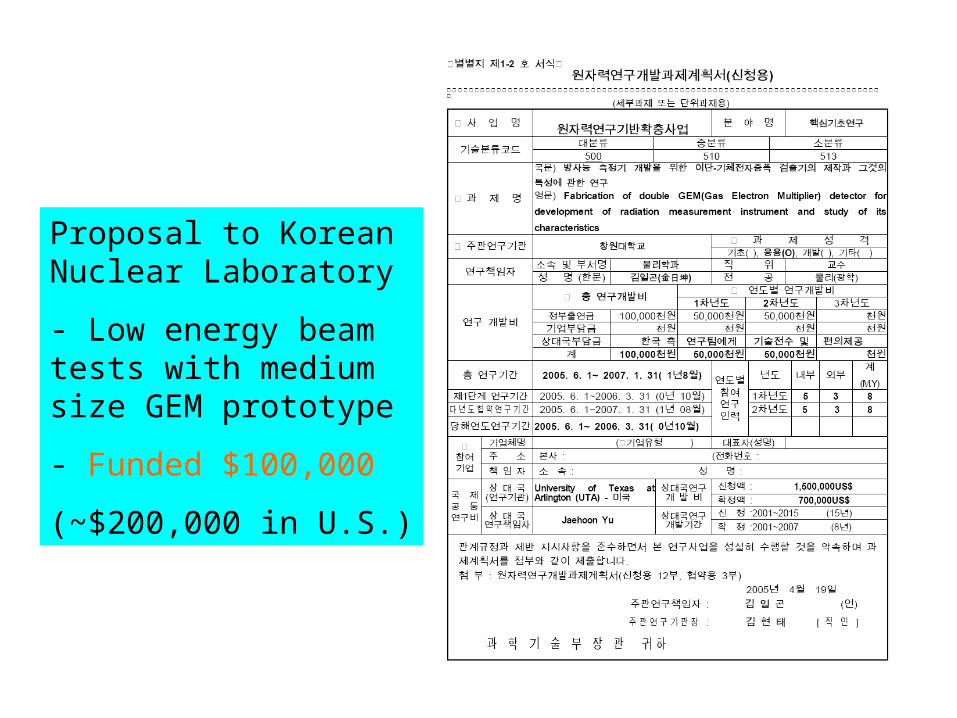
Proposal to Korean Nuclear Laboratory
- Low energy beam tests with medium size GEM prototype
- Funded $100,000
(~$200,000 in U.S.)

Development of GEM sensitive layer
9-layer readout pc-board
3 mm
1 mm
1 mm
Non-porous, double-sided
adhesive strips
GEM foils
Gas inlet/outlet (example)
Cathode layer
Absorber strong back
Fishing-line spacer schematic
Anode(pad) layer
(NOT TO SCALE)

Full-scale (1m3) prototype development
Frame for stretching/flattening GEM foils

Trying out spacer designs, GEM-cathode, GEM-GEM, GEM-Anode
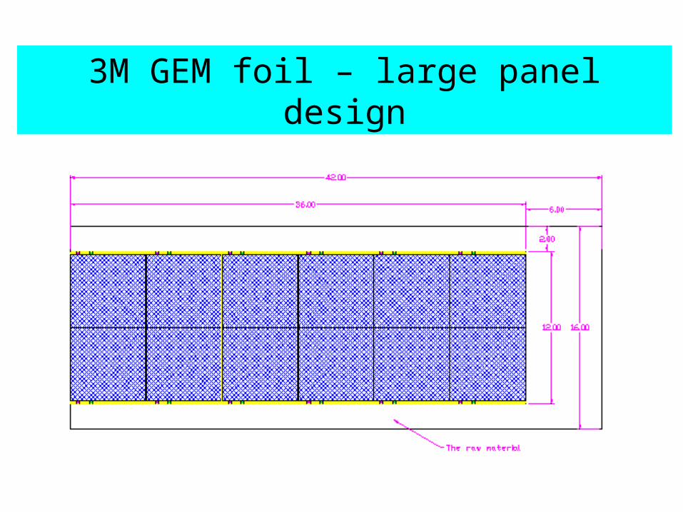
3M GEM foil – large panel design

Full-scale (1m3) prototype development
- 40 layers
- 3 large GEM “panels”/layer
- Double-GEM structure throughout
- 40 layers x 3 panels/layer x 2 x 3 “units”/panel = 720 units
- Fabrication of ~1m x 30cm GEM foils requires some development/process modification by 3M
- Goal is enable large foil production by Fall 2005.

DHCAL/GEM Module concepts
GEM layer slides into gap between absorber sheets
Include part of absorber in GEM active layer - provides structural
integrity
Side plates alternate in adjacent modules

New collaborators(1):
Visit to Tsinghua University, IHEP BeijingDeveloping interest in China for Linear Collider
Detector groups at Tsinghua and IHEP building first GEM prototypes – learning curve, but great facilities and detector expertise.
-> Tsinghua will receive 3M 30cm x 30cm foils and build prototype for comparison with UTA (and others)
-> Tsinghua/IHEP investigating local GEM foil production.
-> Tsinghua has readout system for BES-muon that will work for next GEM/DHCAL prototype (30cm x 30cm), using Fermilab amplifier cards. U.Washington/Tsinghua
-> Use beam at IHEP for GEM prototype tests?

New collaborators(2): Korean Groups
Changwon National UniversityLarge collaboration of Physics and Engineering
faculty;generic GEM research and test beam work at KAERI.
Korean Atomic Energy Research InstituteFive years of GEM research for radiation detectors. Will
be used for characterization (using test beam) of our large GEM detectors.
Proposals submitted:DGEM fabrication+characterization $100K (awarded!) ,
2 years, to KST.GEM applications (Portable Rad. Det. + TEM) $300K, 3
years, to KST.
GEM/DHCAL work
We welcome others to join us!
GEM’s are interesting to work with, and are finding wider applications.
There is still much to do to for the full test of a GEM-based DHCAL system!

To do list for hardware• Large GEM foil development and testing, making it cost
effective• Development of construction technique for GEM planes,
including 30cm x 1m chambers• (Semi)-automation for assembly for large scale GEM planes• Beam and cosmic test of 30x30cm2 stack• Readout of 30x30cm2 stack (U. Washington and IHEP,
Beijing)• Anode board for 30x30cm2 stack• Construction of chambers for 1m3 test beam stack (UTA)• Setting up 1m3 GEM stack at MTBF• Data taking of 1m3 stack• Analyses of cosmic and beam test data• Design of GEM/DHCAL for SiD
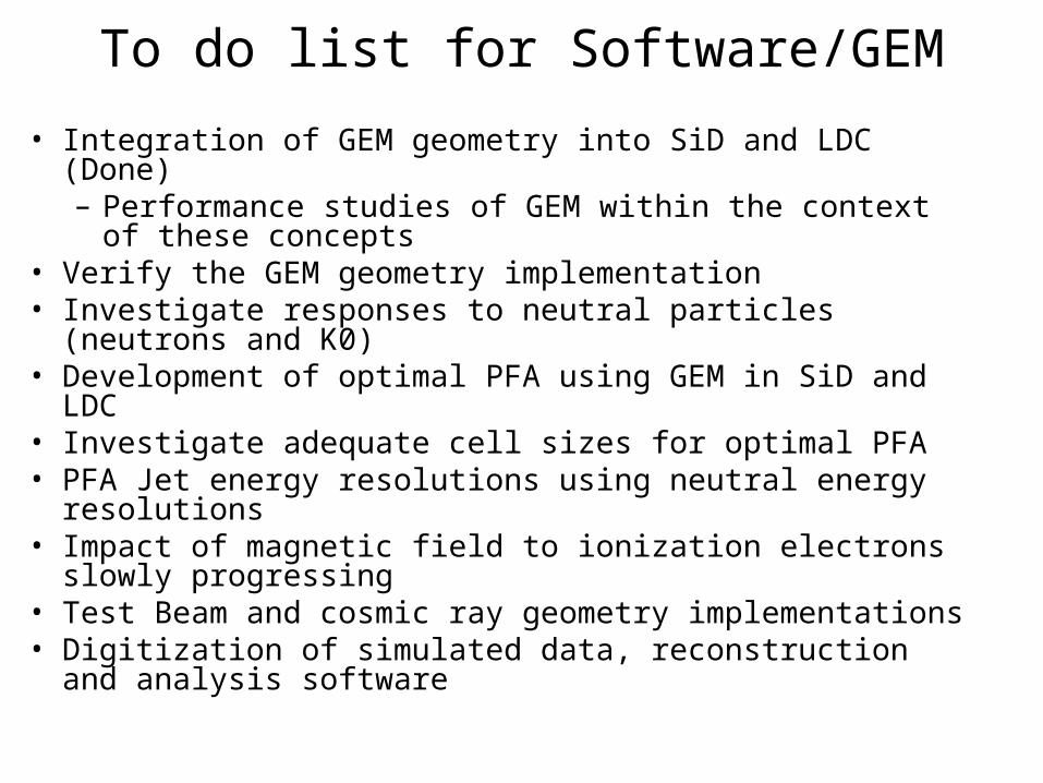
• Integration of GEM geometry into SiD and LDC (Done)– Performance studies of GEM within the context of
these concepts• Verify the GEM geometry implementation• Investigate responses to neutral particles (neutrons and
K0)• Development of optimal PFA using GEM in SiD and LDC• Investigate adequate cell sizes for optimal PFA• PFA Jet energy resolutions using neutral energy
resolutions• Impact of magnetic field to ionization electrons slowly
progressing• Test Beam and cosmic ray geometry implementations• Digitization of simulated data, reconstruction and analysis
software
To do list for Software/GEM

CONCLUSIONS
- Prototype studies of GEM detector
- Much learned about construction and operation of GEM’s
- Technology well suited to implementation of digital hadron calorimetry
- About to construct 500-channel system
- Plans for 1m3 test beam stack in progress.

G10 Frame 30cm x 30cm

G10 Frame 30cm x 30cm
0
50
100
150
200
250
300
350
400
1 11 21 31 41 51 61 71 81 91 101 111 121 131 141 151 161 171 181 191
Sr-90,Ar:Co2=80:20V=409v(2150v),Scintillator Trig