gas flaring reduction projects - world...
TRANSCRIPT

Gas Flaring Reduction Projects
Framework for Clean Development Mechanism (CDM) Baseline Methodologies
Revised Printing April 2005
THE WORLD BANK

© 2005 The International Bank for Reconstruction and Development / The World Bank 1818 H Street, NW Washington, DC 20433 Telephone 202-473-1000 Internet www.worldbank.org E-mail [email protected] All rights reserved. Revised printing April 2005 First printing September 2004 The findings, interpretations, and conclusions expressed herein are those of the authors and do not necessarily reflect the views of the GGFR Partners, or the Board of Executive Directors of the World Bank and the governments they represent.
The World Bank does not guarantee the accuracy of the data included in this publication and accepts no responsibility whatsoever for any consequence of their use.
Rights and Permissions
The material in this work is copyrighted. Copying and/or transmitting portions or all of this work without permission may be a violation of applicable law. The World Bank encourages dissemination of its work and will normally grant permission promptly.
For permission to photocopy or reprint any part of this work, please send a request with complete information to the Copyright Clearance Center, Inc., 222 Rosewood Drive, Danvers, MA 01923, USA, telephone 978-750-8400, fax 978-750-4470, www.copyright.com.
All other queries on rights and licenses, including subsidiary rights, should be addressed to the Office of the Publisher, World Bank, 1818 H Street NW, Washington, DC 20433, USA, fax 202-522-2422, e-mail [email protected].
iii
Acknowledgments This report is one of the outputs of the Global Initiative on Gas Flaring Reduction, led by the World Bank Group in collaboration with the Government of Norway. The Initiative was transformed into the Global Gas Flaring Reduction Public Private Partnership (GGFR) at the World Summit on Sustainable Development held in Johannesburg in August 2002. The GGFR aims to support national governments and the petroleum industry in their efforts to reduce flaring and venting of gas associated with the extraction of crude oil.
In addition to the World Bank this Partnership currently comprises the governments of Algeria, Angola, Chad, Equatorial Guinea, Ecuador, Indonesia, Nigeria, the region of Khanty Mansiysk in Russia, Canada, Norway, and the United States of America. The following oil companies, BP, ChevronTexaco, ENI, ExxonMobil, Norsk Hydro, Shell, SNH, Sonatrach, Statoil, and TOTAL, as well as OPEC are also partners.
This report was prepared by a team from ECON Analysis managed by Torleif Haugland with contributions made by Paul Parks, Ashvini Sharma, Randall Spalding-Fecher and Deborah Stowell. The development of the report was led by Calliope Webber from the GGFR core team in the Bank together with significant collaboration by Johannes Heister and Lasse Ringius from the Methodology and Quality Assurance team of the Bank’s Carbon Finance Business. Highly valuable input and support was provided by specialized consultants, the GGFR core team, World Bank Group staff, and GGFR partners. Several GGFR workshops and CDM conferences provided the basis for extensive discussions and valuable input to the development of the report. Esther Petrilli, World Bank Oil and Gas Policy Division, was responsible for editing and formatting the document.


v
Contents Acknowledgments ............................................................................................. iii Abbreviations and Acronyms ........................................................................... ix Units of Measure ................................................................................................ ix Executive Summary ............................................................................................ 1 1 Introduction ............................................................................................. 9
1.1 The CDM and Gas Flaring Reduction............................................ 9 1.2 The CDM and Baseline Methodologies ....................................... 10
2 Structure and Development of a Methodology....................................... 13 2.1 Key Concepts .............................................................................. 13
2.1.1 Baseline Approaches, Methodologies, and Scenarios..... 13 2.1.2 Project Boundaries and Leakage..................................... 14
2.2 Approaches to Baseline Methodologies ...................................... 15 2.2.1 Three Approaches ........................................................... 15 2.2.2 Suitable Approaches for GFR projects ............................ 15
2.2.3 Projects Already Underway ......................................................... 17 2.3 Guiding Principles........................................................................ 18 2.4 Key Elements of Baseline Methodologies ................................... 19 2.5 Applicability/Scope of GFR Baseline Methodologies................... 20
2.5.1 Emissions Sources from the Gas Value Chain ................ 21 2.5.2 Options for Developing AG and Impact on the Gas Value
Chain................................................................................ 22 2.5.3 A Modular Approach to Baseline Methodologies ............. 23 2.5.4 New Upstream Elements ................................................. 23 2.5.5 Modules for Downstream Emission reductions................ 24
3 Additionality............................................................................................... 27 3.1 Additionality in Baseline Methodologies ...................................... 27 3.2 The EB Additionality Tool ............................................................ 28
3.2.1 Step 0: Projects That Started Prior to Registration .......... 28 3.2.2 Step 1: Identification of Alternatives................................. 29 3.2.3 Step 2: Investment Analysis............................................. 30 3.2.4 Step 3: Barrier Analysis ................................................... 30 3.2.5 Step 4: Common Practice ................................................ 30 3.2.6 Step 5: Impact of CDM Registration ................................ 30 3.2.7 Previous EB Guidance on Assessing Additionality .......... 31
3.3 Assessing Additionality for GFR Projects .................................... 32 3.3.1 Regulatory Requirements ................................................ 32 3.3.2 Economic and Financial Assessment .............................. 32 3.3.3 Barrier Analysis................................................................ 34 3.3.4 Common Practice ............................................................ 34
3.4 Constructing an Additionality Tool for GFR Methodologies ......... 34 3.5 Considering Country Policies....................................................... 36 3.6 Implications of the Voluntary Standard ........................................ 37
4 Project Boundary and Leakage................................................................ 39 4.1 How to Determine the Project Boundary ..................................... 39
4.1.1 Principles ......................................................................... 39

vi
4.1.2 Project Types ................................................................... 40 4.1.3 Multi-country Projects ...................................................... 41
4.2 How to Determine Leakage ......................................................... 41
5 Data and Monitoring.................................................................................. 43 5.1 Key Parameters ........................................................................... 43 5.2 Data Sources and Availability ...................................................... 43 5.3 Uncertainties................................................................................ 44 5.4 Transparency and Conservatism................................................. 44 5.5 Monitoring Methodology Elements .............................................. 45
Annex 1 CDM Primer .................................................................................... 47 A.1.1 The CDM after Marrakech ........................................................... 47 A.1.2 The CDM Project Cycle ............................................................... 48 A.1.3 Methodology Approval Process................................................... 49
Annex 2 GFR and the CDM .......................................................................... 53 A.2.1 Key Features of GFR Projects..................................................... 53 A.2.2 The Gas Value Chain .................................................................. 53 A.2.3 GHG Emissions along the Gas Value Chain ............................... 55
Annex 3 Modules for downstream emission reductions .......................... 59 A.3.1 Grid-Connected Electricity Generation ........................................ 59
A.3.1.1 Introduction ................................................................ 59 A.3.1.2 Background to the Methodology ................................ 59 A.3.1.3 Calculating the Baseline Emissions Rate .................. 60 A.3.1.5 Key Issues ................................................................. 61
A.3.2 Industrial Fuel Switching............................................................. 61 A.3.2.1 Introduction ................................................................ 61 A.3.2.2 Calculating the Baseline Emissions Rate .................. 62
Annex 4 Summary of the Approved Baseline Methodology AM009........ 63 A.4.1 Applicability.................................................................................. 63 A.4.2 Additionality ................................................................................. 63 A.4.3 Project Boundary ......................................................................... 64 A.4.4 Baseline Emissions...................................................................... 64 A.4.5 Project Emissions ........................................................................ 64 A.4.6 Leakage....................................................................................... 65
A.4.6.1 Leakage Emissions Comprise ................................... 65 A.4.7 Emission Reductions ................................................................... 65
Annex 5 Approved Methodologies as of March 2005 .............................. 67 Annex 6 Glossary of CDM Terms................................................................ 73 Annex 7 Proposed New Methodology Formats ......................................... 81
A.7.1 Baseline (CDM-NMB) .................................................................. 81 Section A Identification of Methodology .................................. 81 Section B Overall Summary Description ................................. 81 Section C Choice of and Justification As to Why One of the
Baseline Approaches Listed in Paragraph 48 of CDM Modalities and Procedures is Considered to be the Most Appropriate..................................................... 82
Section D Explanation and Justification of the Proposed New Baseline Methodology............................................. 82
vii
Section E Data Sources and Assumptions.............................. 84 Section F Assessment of Uncertainties (Sensitivity to Key
Factors and Assumptions) ...................................... 84 Section G Explanation of How the Baseline Methodology Allows
for the Development of Baselines in a Transparent and Conservative Manner ....................................... 84
A.7.2 Monitoring (CDM-NMM)............................................................... 84 Section A Identification of Methodology: ................................. 84 Section B Proposed New Monitoring Methodology ................. 85
List of Figures
Figure 2.1 Relationship Among Baseline Approach, Methodology, and Scenario................................................................................. 16
Figure 2.2 Schematic Illustration of the Project Activity as Presented in AM0009/Ver.1........................................................................ 20
Figure 2.3 Example of Emission reduction Formulas ............................. 21 Figure 2.4 Examples of Emissions Impacts along the Gas Chain .......... 23 Figure 2.5 Modular Approach to GFR Project baselines ........................ 24 Figure 3.1 Flowchart for EB Additionality Tool ........................................ 29 Figure 3.2 Tools to Test Additionality for GFR projects .......................... 36 Figure A.1.1 Steps in the CDM Project Cycle ............................................ 49 Figure A.1.2 Steps in the Process of Methodology Approval ..................... 51 Figure A.2.1 Overview of Upstream and Midstream Gas Industry ............. 55
List of Tables
Table 1.1 Methodologies Used for CDM Projects Submitted for Validation.......................................................................... 11
Table A.2.1 Summary of Emissions Sources and Emission reductions Opportunities at Each Stage of the Gas Chain...................... 57


ix
Abbreviations and Acronyms AG Associated gas API American Petroleum Institute CAPEX Capital Expenditures CDM Clean development mechanism CDM-NBM CDM new baseline methodology form CDM-NMM CDM new monitoring methodology form CERUPT Certified Emission Reduction Unit Procurement
Tender CH4 Methane CHP Combined heat and power systems CO2 Carbon dioxide CO2e Carbon dioxide equivalents COP Conference of the Parties COP/MOP Conference of the Parties serving as the Meeting of
the Parties DNA Designated national authority DOE Designated operational entity EB CDM executive board ERUPT Emission Reduction Unit Procurement Tender EU European Union GFR Gas flaring reduction GGFR Global Gas Flaring Reduction Public-Private
Partnership GHG Greenhouse gas(es) GTL Gas-to-liquids GWh Gigawatt hours H2S Hydrogen sulfide HFC Hydrofluorcarbons IEA International Energy Agency IPCC Intergovernmental Panel on Climate Change IPIECA International Petroleum Industry Environment
Conservation Association IRR Internal rate of return LFG Landfill gas LNG Liquefied natural gas LPG Liquefied petroleum gas LRMC Long run marginal cost Meth. Panel Baseline and Monitoring Methodology Panel MWh Megawatt hours N20 Nitrous oxide NGL Natural Gas Liquids NM New methodology NMB New methodology baseline NMM New methodology monitoring

x
NPV Net present value OECD Organization for Economic Cooperation and
Development OGP International Organization of Oil and Gas Producers OPEX Operational Expenditures PCF Prototype Carbon Fund PDD Project Design Document PSA Production sharing agreement QA Quality assurance QC Quality control RE Renewable energy UNFCCC United Nations Framework Convention on Climate
Change WBCSD World Business Council for Sustainable
Development WRI World Resources Institute
Units of Measure GJ Gigajoule GWh Gigawatt hour Kg Kilogram Km Kilometer kWh Kilowatt hour m3 Cubic meters MCM Million cubic meters MW Megawatt MWh tCO2
Megawatt hours Tons of carbon dioxide

1
Executive Summary Abstract Flaring of associated gas contributes significantly to the global emissions of greenhouse gases; flaring emissions are currently estimated to be 300 million tons of carbon dioxide equivalents (CO2e) per year. The Clean Development Mechanism (CDM) can help stimulate investments in projects that reduce flaring and venting of associated gas. These projects will in turn be instrumental in defining and furthering the role of the CDM in gas flaring reductions.
The CDM rules require a CDM project developer to use a baseline methodology approved by the CDM executive board (EB). If an appropriate methodology does not exist, the project developer must develop a new baseline methodology to be forwarded for approval to the EB. To date, only one baseline methodology for flaring reduction projects has been approved, and the overall applicability of this methodology is probably relatively narrow. Several more methodologies need to be developed and approved to cover the range of project options in this sector. Drawing on recent decisions by the CDM executive board and recommendations from the Methodology Panel, this report presents a framework for constructing such methodologies and outlines the tools that can be used to demonstrate additionality.
The original report presented developments and discussions held up to June 2004, while this version includes updates to April 2005.
Background For more than a decade, flaring and venting of associated gas (AG) has remained stable at a level representing global emissions of greenhouse gases (GHG) of about 300 million tons CO2e per year. The Global Gas Flaring Reduction Public Private Partnership (GGFR)1 was established to supplement and strengthen efforts made by governments and companies to reduce and eventually eliminate flaring. The GGFR considers the CDM an important means to achieve flaring reductions and also sees such projects to be central to the objectives of the Kyoto Protocol. With the entry into force of the Kyoto Protocol on 16 February 2005 the importance of the CDM in the GGFR’s work program has taken on new significance. This report contains updated information pertaining to GFR projects and CDM baseline methodologies in order to assist project developers of GFR projects in utilizing the CDM. The report identifies and explains salient factors in developing baseline methodologies for gas flaring reduction projects, and provides a framework to guide project developers in developing baseline methodologies.
A baseline methodology is used to select a baseline scenario, calculate baseline emissions, and determine project additionality for a particular project type or within a particular sector. The CDM rules require that any CDM project 1 See www.worldbank.org/ggfr

2
developer identify and use a baseline methodology approved by the CDM executive board (EB). If an applicable methodology does not exist, the project developer must develop a new baseline methodology to be put forward for approval to the EB.
Currently, only one baseline methodology for gas flaring reduction (GFR) projects is approved by the EB: AM0009, derived from the Rang Dong gas flare reduction project in Vietnam (summarized in Annex 4). Although elements of this methodology are relevant and useful for other projects particularly the monitoring methodology, many project developers may find it difficult to apply the baseline methodology in total. This means that either revisions to the baseline methodology are necessary or that more robust baseline methodologies for GFR projects will have to be developed and approved in order for the CDM to have a major impact on this sector.
Although the specific aim of this study is to contribute to the development of flare reduction baseline methodologies, the broad objective is to assist GGFR partners in utilizing the CDM as a financial incentive to reduce flaring. An important part of this project has been to collect input from key stakeholders to develop guidelines and recommendations for baseline methodologies. The following activities were undertaken:
• Extensive analysis of proposed baseline methodologies and the reviews and decisions of these by the EB and the Meth. Panel
• Consultation with a wide range of CDM experts and stakeholders
• Analysis of proposed GFR activities
These activities helped clarify concepts and outline a framework for project developers to assist them in creating consistent and valid baseline methodologies.
This report does not develop methodologies for specific project categories. Rather, it provides guidance on key concepts and issues, and a framework for constructing baseline methodologies for flare reduction projects. The report supplements other guidebooks relevant for petroleum sector project developers. 2
Key Elements This report discusses two specific criteria that CDM project activities must meet: development of a baseline and a test of the additionality of the project’s emission reductions. Development of the baseline, also known as the baseline scenario, is one of the most important criteria that potential CDM project activities must meet. The CDM rules define a baseline scenario as the “scenario that reasonably
2 For example, Petroleum Industry Guidelines for Reporting Greenhouse Gas Emissions, developed by International Petroleum Industry Environment Conservation Association (IPIECA), Oil and Gas Producers (OGP), and American Petroleum Institute (API); Compendium of Greenhouse Gas Emissions Methodologies for the Oil and Gas Industry developed by API; and The Greenhouse Gas Protocol: Project Quantification Standard developed by World Resources Institute (WRI) and World Business Council for Sustainable Development (WBCSD).

3
represents the anthropogenic emissions by sources of greenhouse gases that would occur in the absence of the proposed project activity.” It is used to show what would most likely have happened to emissions if the project had not occurred, and is therefore a hypothetical situation. The baseline is used in calculating the emission reductions and the corresponding certified emission reductions (CERs) the project is likely to achieve.
The second criterion that projects must adhere to is that of additionality. It has been one of the most difficult issues to define. As with a baseline, additionality is not always a clear cut issue. The CDM rules require that project developers reasonably demonstrate that the emission reductions by the project are additional to those that would have occurred in the absence of the CDM project activity. In other words, project developers will need to show that the project goes beyond business as usual.
According to the CDM rules, the baseline scenario must be derived using an approved baseline methodology. In addition, it must set out a logical framework that clearly addresses three issues:
• Selection of a baseline scenario
• Determination of whether the project is part of the baseline, that is, whether the project is part of the most likely course of development
• Assurance that the project will reduce emissions beyond what would have occurred without the project activity
A baseline methodology is therefore a protocol for selecting the baseline scenario and calculating baseline emissions for a particular project type, or within a specific sector, so as to produce a project-specific baseline scenario.
A baseline methodology contains formulas and algorithms for a particular project type, as well as certain parameters for calculating emissions from the baseline scenario. The methodology also explains how additionality will be tested for project activities using the baseline methodology. The project activity’s emissions are considered additional only if they are not part of the baseline and if the emissions are lower than that of the baseline. A methodology is judged by the logic and transparency of its design and how well it addresses these three issues.
Design Considerations The analysis of decisions and reviews of the baseline methodologies submitted thus far to the EB identified several key lessons and principles that should guide project developers in proposing new baseline methodologies. These general guidelines are as follows:
• Simplicity: Use straightforward, transparent elements that are clearly applicable to the creation of a baseline.
• Precedence: Elements of approved methodologies (for example, emissions factors for power generation, energy efficiency,

4
industrial fuel switching) should be incorporated where appropriate to demonstrate consistency with established methodologies.
• Conservatism: If more than one element (or algorithm, factor, or assumption) is appropriate, then the one that generates the least emission credits should be used.
Given that all GFR projects have common elements and can impact on one or more of the three sectors in the gas value chain (that is, production, transport and processing, downstream use), developing algorithms, such as emissions factors, for the various components of a GFR project may simplify the process of baseline development and project validation.3 A project developer who proposes a new methodology could draw on previously developed elements in designing a methodology for a new project type, or even refer to approved methodologies to calculate the baseline and project emissions factors for downstream elements of the investment. For the upstream component of a project, the baseline emissions are based on the amount of gas that would be flared and vented without the project. Treatment of processing facilities will be dependent on the project, but could be a separate element of the methodology, at least for LNG and GTL. Downstream components would be added to the core upstream component. A number of modules can be developed to establish emissions factors for downstream components of projects, particularly in the power sector and industrial fuel switching, where approved methodologies are available that could be easily adapted to flaring reduction projects. Given the bottom-up process adapted by the EB, the probable course of development is that several additional methodologies will be approved, which in the future could be combined to one or more consolidated methodologies.
Additionality The Kyoto Protocol states that the CDM must provide, “real, measurable, and long-term benefits related to the mitigation of climate change…” and provide “reductions in emissions that are additional to any that would occur in the absence of the certified project activity.” In determining whether the emission reductions from a project activity are additional, the project developer must show that the anthropogenic emissions of GHGs by sources are below those, which would have occurred in the absence of the registered CDM project activity.4 In developing a baseline methodology, project developers must provide an “explanation of how, through use of the methodology, it can be demonstrated that a project activity is additional and therefore not the baseline scenario.”
Using an approved baseline methodology does not automatically confer additionality on the project’s emission reductions, but rather provides a means for
3 For example, the Rang Dong approved methodology contains specific algorithms for calculating carbon dioxide (CO2) emissions and emission reductions that can be used when developing new methodologies. 4 Marrakech Accords, Decision 17 /CP.7, Section G, paragraph 43.
5
testing additionality. In developing a methodology, the developer must describe how the additionality of the emissions reduced by the proposed CDM project activity can be determined through the application of the methodology; whereas, in the Project Design Document (PDD) the project developer must apply the methodology and explain why the emission reductions would not occur in the absence of the proposed project activity, that is, how the project is not included in the baseline scenario.
In October 2004, the EB released the “tool for the demonstration and assessment of additionality,” which project developers may use for additionality assessment when developing a new baseline methodology. The EB tool consists of six sequential steps that project developers are to follow when using this tool. The EB tool is accompanied by a flow chart that illustrates the fact that the additionality tools are primarily sequential—in other words, projects must pass more than one kind of assessment to be considered additional.5 However, the EB has made it clear that project developers may alter its tool or use other tools for demonstrating additionality. Hence tools need not necessarily have the sequential steps of the tool issued by the EB. It should be noted that several of the already approved baseline methodologies only have one tool for assessing additionality rather than multiple tools. In addition, previous guidance from the EB listed four different alternative options for additionality testing that can be used individually.
Regarding baseline methodology for flaring reductions projects, certain additionality issues should be noted:
• Regulatory requirements: Flaring may be prohibited by law and, hence, not be a plausible baseline activity; however, a legal prohibition can be ambiguous. Even where regulation de jure prohibits flaring, in many instances flaring still occurs either because of nonenforcement, exceptions to the regulation, or the low cost of noncompliance. This is recognized in the EB approved tool for additionality testing. The methodology must be broad enough to cover such eventualities and allow the additionality of projects to be tested on a case-by-case basis.
• Qualitative or quantitative assessment: This assessment may be applied to determine whether the potential CDM project would not be viable based on a normal business analysis6 of the project developer. Economic and financial assessments will not be the only determinants of project additionality and often other factors, such as a barrier analysis, should be used to establish project additionality.
5 For example, a project would either have to go through a regulatory screen, barriers, common practice, and impact of CDM registration, or a regulatory screen, investment analysis, common practice and impact of CDM registration, or all five tests sequentially. 6 Business as usual, in this case, means that the project would not be implemented under the normal course of events.
6
• Barriers analysis: This refers to factors generally outside the direct control of the project developer that affect the project’s likelihood of implementation. Barrier analysis can be a critical factor in justifying many CDM GFR project, but, by nature, barriers are specific to the area, regime, or type of project. Thus, a methodology will need to identify and provide a general means to analyze and measure the impact of such barriers in determining project additionality.
• Common practice: Common practice can be used as a justification for additionality if the developer can demonstrate that the project type is not in general use in the proposed area of implementation. Applying this tool requires documentation that common practice in the sector does not include the project type; and, in addition to the project, reference should be made to the practices of other companies.
Project Boundary and Leakage In developing a CDM project activity, project developers must be able to clearly define the project boundary and the project’s potential for leakage. Under the CDM rules, the project boundary must encompass all anthropogenic emissions of greenhouse gas (GHG) emissions by sources under the control of the project developers that are significant and reasonably attributable to the project, while leakage is defined as the net changes of anthropogenic emissions by sources of GHGs that occur outside the project boundary and that are measurable and attributable to the project.
The baseline methodology must specify the process and principles to be applied in determining the boundaries for the category of projects covered by the methodology. For GFR projects this means that all emissions from extraction, capture, and processing should be included in the project boundary, including any fugitive and combustion emissions at the production and processing sites. Fugitive and combustion emissions from transport and distribution infrastructure that are part of the project investment would also be included in the project boundary.
Downstream emissions from end-use sites may be included in the project boundary if the project owner has investment in these activities, can identify the dedicated end use of the gas downstream, and is contractually able to monitor the direct impacts of the project and claim certified emission reductions (CERs).
The Global Gas Venting and Flaring Reduction Voluntary Standard In May 2004, the GGFR Partnership announced a Voluntary Global Standard for Gas Venting and Flaring Reduction. The Standard outlines a plan of action, including implementation of the Standard by partner companies and countries. The Voluntary Standard should not influence the baseline for flare reduction activities. The Standard is a process not a fixed target and should be seen as an aspiration to achieve reduction and, eventually, elimination of flaring. In

7
addition, the EB has ruled that policies put in place after November 2001 should not be considered in developing a baseline.7
The approach set forth in the Standard is intended to support other flare reduction initiatives and go beyond prevailing flaring and venting practices, which would otherwise occur in many countries. One way to achieve the aspiration of the Standard is to use the CDM. When relevant, project developers can reference the Standard in the baseline methodology and clarify how it relates to the additionality assessment.
Conclusions and Next Steps This report aims to clarify concepts and outline a framework to help project developers create transparent, consistent, and justifiable baseline methodologies, so that GFR projects can qualify for CDM status. From a GGFR perspective, it is vital that methodologies developed and submitted to the EB are appropriate to the GGFR partners’ needs and are broadly applicable to GFR projects. Only in this way can the GGFR partners ensure that their concerns and viewpoints in this area are taken into account and are incorporated into CDM baseline methodologies.
This report concludes that several new gas flaring methodologies will be required to encompass the full range of gas flaring CDM projects. Once a body of GFR methodologies has been established, the EB may then choose to create a smaller subset of consolidated methodology(ies) that should cover a broad range of GFR projects. Regardless, once methodologies have been tested, that is, applied by more than one project, costs of developing Project Design Documents (PDDs) will be lowered and uncertainty over what qualifies as a CDM project activity will be reduced.
Lower transaction costs and simplified robust CDM procedures, will be key to facilitating more flare reduction projects. This report is designed to contribute to such an outcome.
7 EB 16 Report, Annex 3, “Clarifications on the treatment of national and/or sectoral policies and regulations (paragraph 45 (e) of the CDM Modalities and Procedures) in determining a baseline scenario.”

9
1 Introduction This section presents the context of the report, the relevance of the clean development mechanism (CDM) for gas flaring reduction (GFR) projects, and an introduction to CDM baseline methodologies.
1.1 The CDM and Gas Flaring Reduction Flaring and venting of associated gas (AG) contribute significantly to global emissions of greenhouse gases (GHGs). Specifically, these activities are currently estimated to result in about 300 million metric tons of carbon dioxide equivalents (CO2e) per year. This level may rise as oil production increases in countries and regions that currently flare a large share of their AG. The Global Gas Flaring Reduction Public Private Partnership (GGFR) works to supplement and strengthen efforts made by governments and companies to reduce and eventually eliminate flaring of AG. The CDM can be a valuable tool in achieving this goal by stimulating investments in flare reductions. The entering into force of the Kyoto Protocol on 16 February 2005 has further underlined the potential contribution from the CDM to help finance flare reduction projects and provide other sustainable development benefits.
The GGFR Report No. 2, Kyoto Mechanisms for Flaring Reductions,8 explored how and under what circumstances GFR projects can earn carbon credits. The report concluded that GFR projects can offer results that are central to the objectives of the Kyoto Protocol and the CDM because often they do the following:
• Offer large, real, measurable, and long-term emission reductions;
• Have relatively moderate transaction costs;
• Are central to the host country policies in terms of resource management, environment, and fiscal benefits;
• Can serve to support sustainable development goals on both a national and local basis; and
• Can mobilize substantial technological, financial, and political resources from international energy companies.
These results formed the basis for several new activities in the GGFR’s work program to promote the use of the Kyoto Mechanisms and to accelerate flaring reduction investments.
Guidelines and recommendations for establishing CDM baseline methodologies, presented here, represent one of these efforts. Although the specific aim of this study is to contribute to the development of flare reduction baseline methodologies, the broad objective is to assist GGFR partners in using the CDM. The goal is to decrease CDM transaction costs and enhance investment in flare 8 See http://www.worldbank.org/ogmc/ggfr report published 2003.

10
reduction projects while assuring environmental integrity and the overall objectives of the CDM.
1.2 The CDM and Baseline Methodologies The CDM rules9 require a CDM project developer to use a baseline methodology10 approved by the CDM executive board (EB) in preparing a baseline. If an appropriate methodology does not exist, the project developer must develop a new baseline methodology to be put forward for approval to the EB. Approved methodologies contain descriptive information on their “applicability,” that is, the conditions that a project must meet in order to use the methodology. The “applicability” of a methodology can be narrow, or, as with the consolidated methodologies, inclusive. To date, most baseline methodologies have been developed with restrictions or limitations on the types of projects that can use a methodology.
At the time of writing, only one baseline methodology for GFR projects had been approved by the EB: AM0009 Recovery and utilization of gas from oil wells that would otherwise be flared, derived from the Rang Dong Oil Field Associated Gas Recovery and Utilization Project located in Vietnam (see Annex 4).11 This means that more baseline methodologies for GFR projects are likely be developed and presented for approval.
One of the difficulties inherent in the CDM system, is that the CDM rules require that baselines be developed and projects approved on a case-by-case basis (the so-called bottom-up approach), rather than through a more standardized top-down approach. One of the ways the CDM attempts to compensate for this is through development and application of baseline methodologies. These methodologies give guidance to project developers in the assumptions and parameters they are to use in developing baseline scenarios for their projects. It also provides designated operational entities (DOEs) with a framework for evaluating baselines and validating projects. Again, however, the CDM rules specify that new baseline methodologies must be submitted with a draft PDD, meaning that methodologies are developed “bottom up” based on specific projects. This was seen as essential at COP-7 in order to allow the CDM project development process to start immediately. The EB does not, therefore, have a mandate to develop methodologies “top down” but can only work with what is submitted by project developers.12 One of the results of this process is that, after the rejection of eight 9 For simplicity and clarity, in this report the term “CDM rules” will encompass the CDM modalities and procedures and any guidance issued by the EB, COP and COP/MOP. 10 A baseline methodology is a means to select a baseline scenario, calculate emissions for a baseline scenario applicable to a particular project type or particular sector, and determine project additionality. 11 AM0009 is the first gas flaring–related methodology to be submitted to the CDM executive board, as NM0026. Complete information is provided at http://cdm.unfccc.int/methodologies. 12 The exception is for small scale projects (that is <15MW energy production, <15GWh energy savings, or <15kt emissions), where the EB was given mandate to develop standard methodologies.
11
methodologies during the first round of methodology reviews, project submissions seemed to err on the side of conservativeness and suggesting a narrow applicability for the proposed methodology.
If a broad range of methodologies for GFR projects is developed, the EB is likely to consolidate the methodologies. In cases where several methodologies have been approved for projects within a specific category, that is, landfill gas capture, the EB has published consolidate methodologies that draw on key elements from approved methodologies and apply them to a range of projects within a sector. For example, ACM0001 (derived from four methodologies) covers almost all landfill gas projects, whether the gas is utilized for energy or not; and ACM0002 covers a wide range of renewable electricity projects. The Meth. Panel has also proposed that one be developed for biomass power generation projects.
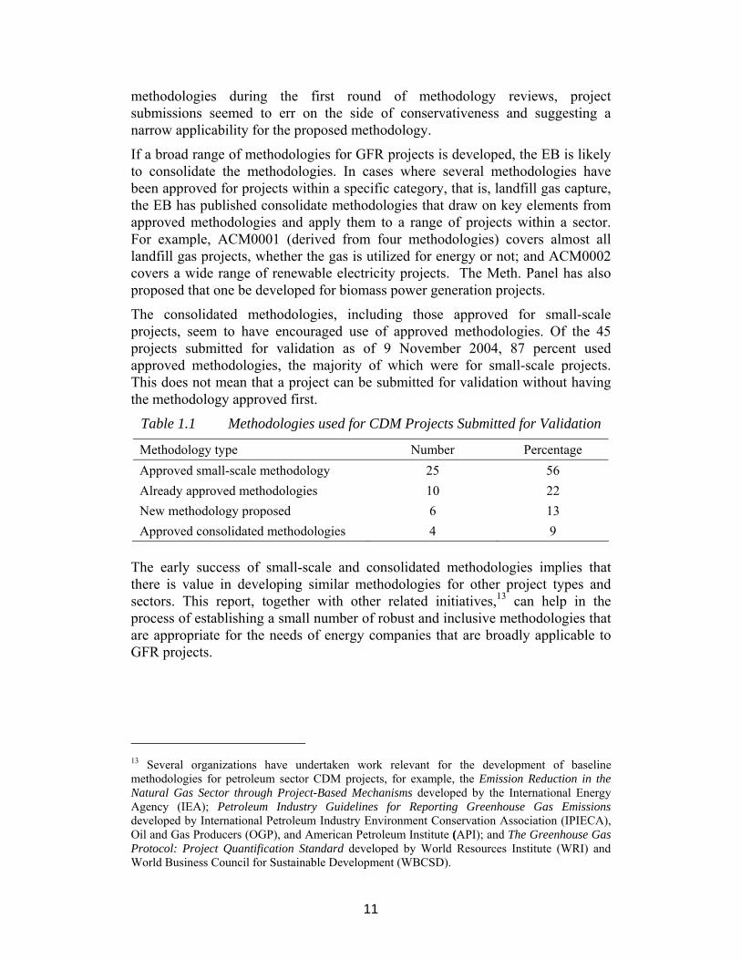
The consolidated methodologies, including those approved for small-scale projects, seem to have encouraged use of approved methodologies. Of the 45 projects submitted for validation as of 9 November 2004, 87 percent used approved methodologies, the majority of which were for small-scale projects. This does not mean that a project can be submitted for validation without having the methodology approved first.
Table 1.1 Methodologies used for CDM Projects Submitted for Validation
Methodology type Number Percentage Approved small-scale methodology 25 56 Already approved methodologies 10 22 New methodology proposed 6 13 Approved consolidated methodologies 4 9
The early success of small-scale and consolidated methodologies implies that there is value in developing similar methodologies for other project types and sectors. This report, together with other related initiatives,13 can help in the process of establishing a small number of robust and inclusive methodologies that are appropriate for the needs of energy companies that are broadly applicable to GFR projects.
13 Several organizations have undertaken work relevant for the development of baseline methodologies for petroleum sector CDM projects, for example, the Emission Reduction in the Natural Gas Sector through Project-Based Mechanisms developed by the International Energy Agency (IEA); Petroleum Industry Guidelines for Reporting Greenhouse Gas Emissions developed by International Petroleum Industry Environment Conservation Association (IPIECA), Oil and Gas Producers (OGP), and American Petroleum Institute (API); and The Greenhouse Gas Protocol: Project Quantification Standard developed by World Resources Institute (WRI) and World Business Council for Sustainable Development (WBCSD).


13
2 Structure and Development of a Methodology The CDM rules state that a project developer must “forward the proposed methodology, together with the draft PDD, including a description of the project and identification of the project developers, to the EB for review.” Such a process requires that the project be in a fairly advanced state of development since a baseline study and monitoring plan, that is, an example of the application of the proposed new methodologies, must be included in the draft PDD.
Initially, proposed baseline methodologies were presented as Annex 3 to the PDD. In mid-2004, the EB introduced a freestanding form for submitting new baseline and monitoring methodologies (CDM-NMB, refer to Annex 7, and also available at http://cdm.unfccc.int). The CDM-NMB form covers the following:
• Section A: Identification of methodology
• Section B: Overall summary description
• Section C: Choice of and justification for the baseline approaches listed in paragraph 48 of CDM modalities and procedures to be considered the most appropriate
• Section D: Explanation of and justification for the proposed new baseline methodology
• Section E: Data sources and assumptions
• Section F: Assessment of uncertainties (sensitivity to key factors and assumptions)
• Section G: Explanation of how the baseline methodology allows for the development of baselines in a transparent and conservative manner
The remainder of this chapter focuses on the key concepts and guiding principles for developing a GFR baseline methodology. In addition, the applicability of methodologies and their relation to the gas value chain are considered before addressing specific approaches to baseline methodology development.
2.1 Key Concepts Understanding key concepts in the CDM rules is critical to the development of sound methodologies, particularly since many of the terms used in the CDM have meanings specific to the CDM that differ from traditional usage, such as the term “leakage.” Additionality is discussed in depth in the following chapter and is therefore not addressed here.
2.1.1 Baseline Approaches, Methodologies, and Scenarios
The term baseline or baseline scenario is used to describe the case against which the impacts of any emission reductions measure or program are evaluated. The baseline scenario for a CDM project activity is a hypothetical scenario of what would most likely have happened to emissions in the absence of the CDM project

14
activity. The baseline scenario is also used to calculate the amount of emission reductions the potential project activity is likely to generate, and once the emission reductions are verified and certified, the resulting credits become a marketable commodity. Certified emission reduction units (CERs) are carbon credits that can be bought, sold, banked, or used in the international emissions trading system or in domestic trading schemes that recognize CERs as a valid commodity.14
As previously mentioned, the baseline scenario must be developed through application of an approved baseline methodology. The methodology is a protocol for selecting the baseline scenario and calculating baseline emissions for a particular project type or within a particular sector so as to produce a baseline scenario. A baseline methodology contains formulas and algorithms for estimating emissions in the baseline and the project activity, as well as for calculating emission reductions. The methodology must also explain how through its use the additionality of emissions will be determined, that is, tested (see chapter 3).
In addition to requiring projects to use approved baseline methodologies, the CDM rules spell out three broad approaches that baseline methodologies should follow (see section 2.2).
2.1.2 Project Boundaries and Leakage
CDM project activities may either be part of larger and more complex energy infrastructure projects or a standalone activity that uses existing infrastructure. Determining the boundaries of the proposed CDM project activity is critical. This includes determining the proposed project activity’s impact on emissions, which emissions are covered in the baseline, and what effect, if any, the project activity has on emissions outside these boundaries. These issues are determined through two concepts: project boundaries and leakage.
A project boundary must be defined to include all GHG emissions and sources as well as a physical delineation for the CDM project activity. All GHG emissions by sources that are under the control of the project developers and are significant and reasonably attributable to the project activity must be included within the project boundary.
In the CDM, leakage refers to changes in emissions due to the CDM project activity that occur outside the project’s boundaries rather than physical leakage as commonly referred to in the oil and gas sector (for example, fugitive emissions from pipelines). The exact definition of leakage under the CDM rules is: “the net change of anthropogenic emissions by sources of greenhouse gases (GHG) which occurs outside the project boundary, and which is measurable and attributable to the CDM project activity.”
14 The Marrakech Accords and national rules and regulations determine the extent to which emission reductions can be traded as certified emission reduction units (CERs) and used as “compliance tools” toward emission reductions targets in Annex 1 countries.

15
2.2 Approaches to Baseline Methodologies 2.2.1 Three Approaches
The CDM rules require that in choosing a baseline methodology project developers select from one of the three approaches contained in the CDM rules.15 The approaches for baseline methodologies are provided in paragraph 48 of the CDM rules.16 They are as follows:
• Approach A: Existing actual or historic GHG emissions, as applicable
• Approach B: Emissions from a technology that represents an economically attractive course of action, taking into account barriers to investment
• Approach C: Average emissions of similar projects undertaken in the previous five years, in similar social, environmental, and technological circumstances, and whose performance is in the top 20 percent of their category
According to experts interviewed for this project, the choice of approach is not a key factor in the approval of a methodology. In fact, the EB recognizes that the three approaches overlap and that although a methodology is based on one approach, the methods for determining the baseline, additionality, and so forth may contain similarities across the three approaches. Nevertheless, a baseline methodology must be developed using one of the three approaches.
As illustrated in Figure 2.1, one way of interpreting this process is to look at it as moving from the general to the specific. Choosing a baseline approach is the first and most general step in this process. The approach does not include specific guidance on calculating baseline emissions and, therefore, should be viewed as more of a principle than a tool. It will, however, have some implications for the types of data required.
2.2.2 Suitable Approaches for GFR projects
In developing a baseline methodology for GFR projects, the three approaches may have some advantages and disadvantages. Approach A provides an advantage for the upstream portion of a project in that it provides a simple principle for constructing a baseline emissions scenario. Approach B places greater emphasis on the economics of a project which could present some difficulties for project developers. This approach, however, can be combined with other tools to show that, regardless of the economics of the project, other factors make the implementation of the project difficult, that is, barriers to implementation.
15 In section 3 of the CDM-NMB, project developers must select the approach that is most consistent with the project type; only one approach may be used in developing a baseline methodology. 16 The Executive Board has left open the possibility of adding approaches.

16
Figure 2.1 Relationship Among Baseline Approach, Methodology, and Scenario
Approach C is likely to be problematic for GFR projects due to the lack of data on a regional or national “control group” and because typically, within the oil industry, this data is considered confidential. If there are only one or two facilities in a region managing and using AG, these facilities could become the baseline even if they have different geological and economic characteristics than the proposed project area. An exception might be a project that employs very specific technologies for improving flaring efficiency, but it is unclear whether project developers would use this approach in developing a methodology.
Many stakeholders have raised concerns that a baseline methodology for GFR projects, while incorporating economic and financial assessments, should not require economic analysis as the sole determinant of project additionality and baseline development. This concern should be alleviated given EB guidance on additionality. The EB tool for assessing and determining additionality may be used regardless of the approach adopted; as will be discussed in chapter 3, it also incorporates multiple methods or tools for testing additionality. This should also assist project developers in de-linking the tools for testing additionality from the approach used in proposed new methodologies. It is worth noting that this has already occurred in earlier approved methodologies. An example of this is the approved baseline methodology for industrial fuel switching,17 which uses approach A but also incorporates economic and investment barriers in order to test the additionality of the projects emissions.
17 See AM0008 Industrial fuel switching from coal and petroleum fuels to natural gas without extension of capacity and lifetime of the facility.
PPrroottooccooll ffoorr hhooww ttoo ccaallccuullaattee bbaasseelliinnee eemmiissssiioonnss:: •• FFoorrmmuullaass//aallggoorriitthhmmss •• AAddddiittiioonnaalliittyy tteessttiinngg •• PPrroojjeecctt bboouunnddaarriieess aanndd
lleeaakkaaggee
Approaches Methodology Scenario
SSppeecciiffiieedd bbyy tthhee CCDDMM rruulleess ttoo ccoovveerr aallll mmeetthhooddoollooggiieess
AApppprroovveedd bbyy CCDDMM EExxeeccuuttiivvee BBooaarrdd
PPrrooppoosseedd ffoorr ssppeecciiffiicc CCDDMM pprroojjeecctt aaccttiivviittyy
Increasing ssppeecciiffiicciittyy
PPrriinncciipplleess:: AA.. EExxiissttiinngg hhiissttoorriiccaall eemmiissssiioonnss BB.. EEccoonnoommiiccaallllyy aattttrraaccttiivvee ggiivveenn
bbaarrrriieerrss CC.. TToopp 2200%% ppeerrffoorrmmaanncceess llaasstt
ffiivvee yyeeaarrss CDM project emission
Year
GH
G e
mis
sio
n
Baseline emissions
Projectimplementation
CDM project emission
Year
GH
G e
mis
sio
n
Baseline emissions
Projectimplementation
Year
GH
G e
mis
sio
n
Baseline emissions
Projectimplementation

17
An additional question is whether approach A can be used to develop a baseline methodology for green field GFR projects18 as well as brown field GFR projects. For brown field projects, current flaring and venting emissions per unit of AG production are known and should be used in developing a baseline study for a project activity. Green field projects, on the other hand, lack documented current and historic emissions. A project developer, however, will have detailed information on key characteristics of the oil field and project (for example, gas composition, likely flare efficiency) from feasibility studies and testing. For green field projects, using known data combined with conservative standards (for example, 98 percent flaring efficiency) could be nearly as accurate as actual or historic emissions. This would have to be tested in the CDM process through development and application of a baseline methodology.19
2.2.3 Projects Already Underway
Stakeholders have also raised questions as to whether the implementation status of the project (that is, whether it is already in operation) affects the choice of approach or the development of the methodology. Special provisions were made for projects that commenced operation between January 2000 and December 2001.20 Projects under way are not excluded from the CDM and can be “grandfathered” into the CDM. The practical challenge for these projects is to comply with section B.4 of the PDD. This asks for an “explanation of how and why this project is additional and therefore not the baseline scenario.”
Methodologies are developed irrespective of the stage of implementation of the project. As mentioned above, the primary issue for projects that have begun generating emission reduction is to determine whether the emissions are additional to what would have occurred in the absence of the project activity. This has occurred in several proposed methodologies where a series of barrier tests have been proposed that include not only financial viability but also capital availability, institutional barriers, and so on. AM0009, for instance was derived from a project already underway, the Rang Dong project. In reviewing the methodology submitted by the Rang Dong Project developers, Meth. Panel comments suggest that implementation status of the project does not affect the baseline methodology. This has also been borne out in discussions with experts in the preparation of this report.
18 A green field project is an investment at a site where presently there is no associated gas (AG) production and where AG production as a result of the project has to be managed. 19 Because the principle component of both green field and brown field GFR projects is the forecast of gas production, the actual degree of uncertainty between the two types of projects could be very small. 20 The CDM modalities and procedures (paragraph 13, p. 23, FCCC/CP/2001/13/ad2) allow for projects begun in 2000 and 2001 to be eligible for validation and registration as a CDM project activity if submitted for registration before December 31, 2005.

18
2.3 Guiding Principles Analysis of decisions and reviews of the baseline methodologies submitted thus far to the EB identified several key lessons and principles that should be useful in guiding project developers in proposing new baseline methodologies. These general guidelines are as follows:
• Keep the methodology as simple as the project type allows: Complex approaches that are difficult to understand and illustrate have not been well-received. For example, methodologies involving energy sector models have been criticized as impenetrable “black boxes” that are difficult to understand. Conceptually simple, transparent methodologies with well-defined applicability have been among the first to be approved.
• Incorporate elements from approved methodologies: CDM methodologies are being developed on a precedence basis. If elements of approved methodologies can be incorporated into a proposed methodology, this should help to show that it is consistent with existing methodologies and the CDM rules. For example, if a GFR project includes downstream emission reductions from fuel displacement at an industrial site, emissions factors from an approved industrial fuel switching methodology could be incorporated for that component of the project.
• Use the EB tool or a series of tools for determining additionality: As will be discussed in chapter 3, a methodological argument is strengthened through a combination of tools––such as market and/or regulatory barriers, economic and financial assessment––and common (prevailing) practice.
• Ensure the methodology is conservative: As required by the CDM rules, baseline methodologies must be demonstrably conservative. This means that if more than one methodology (or algorithm, factor, or assumption) can be applied, then the one that generates the least emissions credits should be used.
• The methodology must be applicable to more than one project: A methodology should not incorporate project-specific information, and must be applicable to a category of projects. For example, power sector methodologies generally have been for a particular technology but, in some cases, have had additional restrictions on the applicability. The CDM-NBM also asks for “conditions under which the methodology is applicable to CDM project activities,” where the developers can specify how broadly the methodology can be applied within the sector.
• Emphasize monitoring: The baseline methodology has to be accompanied by a monitoring methodology applicable to the project. The monitoring methodology should include information

19
on provisions for collecting data necessary to calculate emission reduction accurately, including ex post calculation of emissions factors when appropriate.21
• Incorporate national policies: The methodology must include a component explaining how the CDM project scenario and baseline scenario will be tested for conformity with national and sectoral policies of the host country.
2.4 Key Elements of Baseline Methodologies All baseline methodologies must address the same basic components: baseline selection, additionality, determination of baseline emissions, determination of project emissions, identification of leakages, and estimation of emission reductions by the project activity.
Selection of the baseline scenario and determination of additionality are conducted through a similar process. In determining what the baseline scenario is, and in order to determine the additionality of a proposed project, all plausible project options should be identified, including the project itself and the business as usual case.22
One method for narrowing down the list of options is to use criteria for screening similar to those listed in the EB’s additionality tool. For instance the first step could be to examine all options to determine whether they comply with existing regulations and/or are considered common practice in the project area. Those options which do not would be eliminated. The remaining options would then be subject to investment and/or barrier analysis with the purpose of selecting the baseline scenario. These steps could involve the following:
• Analysis of barriers to implementation, with those scenarios facing prohibitive barriers eliminated.
• Estimation of costs and calculation of present value of future costs. The economic attractiveness is assessed for those options that are feasible in technical terms and that are identified as legally permitted by law or other (industrial) agreements and standards.
The outcome results in the identification of the baseline scenario from a set of plausible alternatives and provides a test on the additionality of emissions from the proposed project activity. If the baseline scenario is not the project, and the project is not common practice, then the project is additional. 21 While monitoring should be used to track impacts, such as fugitive emissions from production, processing, and transport, the EB has cautioned against the use of ex post emissions factors for power generation (EB9 Report, Annex 3, page 2). For downstream baseline methodology modules, therefore, emissions factors should be established ex ante and reported in the PDD, using the protocols laid out in the baseline methodology. 22 For instance, in AM0009, five options are listed for purposes of determining additionality. These options could instead be used as a plausible alternative for determining the baseline scenario.

20
Once the baseline scenario has been identified, the boundary of the project activity must also be determined. This should include a descriptive as well as schematic illustration of the project boundaries (see Figure 2.2). All sources of GHG emissions directly related to the proposed project activity must be identified, as well as any emissions outside the project boundary directly attributable to the project and measurable, must be accounted for. The methodology must also identify any sources of emissions that are to be monitored. Formulas for the estimation of emissions from the project activity must be included in the methodology. Finally a method for calculating the estimated emission reductions from the project activity in comparison to estimated baseline emissions (taking into account any leakages) must be provided.
Figure 2.2 Schematic Illustration of the Project Activity as Presented in AM0009/Ver.1
Emission reductions are calculated as the difference between baseline and project emissions, taking into account any adjustments for leakage. An example of this is show in Figure 2.3 below, from the approved methodology AM0009.
2.5 Applicability/Scope of GFR Baseline Methodologies As previously mentioned, approved baseline methodologies are defined in part by their applicability. There is a question of how broadly applicable a methodology should be across different sectors, technologies, regions, and so on.23 Should the methodology, for example, be applied to projects of a particular technology or restricted to a particular technology in countries with certain regulatory
23 If methodologies are too narrow, the number of methodologies could be too large, causing difficulty in determining the appropriate methodology for a given project and reducing the ability to lower transaction costs. Conversely, if methodologies are too broad, they may not sufficiently capture the specific characteristics of a given project and, thus, be less accurate at projecting baseline emissions.

21
environments? In the following sections we discuss various aspects related to applicability such as emissions sources and options for developing AG.
Figure 2.3 Example of Emission reduction Formulas
Formula for calculating emission reductions in AM0009:
EFy = BLy − PECO2,gas,y − PE CO2,other fuels,y - PECH4,plants,y - PECH4,pipeline,y - Ly
where:
EFy Are the emission reductions of the project activity, adjusted for leakage, during the period y in tons of CO2 equivalent.
BLy Are the baseline emissions during the period y in tons of CO2 equivalents.
PECO2,gas,y Are the CO2 emissions from the project activity due to combustion, flaring or venting of recovered gas during the period y in tons of CO2.
PECO2,other
fuels,y Are the CO2 emissions due to consumption of other fuels than the recovered gas due to the project activity during the period y in tons of CO2.
PECH4,plants,y Are the CH4 emissions from the project activity at the gas recovery facility and the gas processing plant during the period y in tons of CO2 equivalents.
PECH4,pipeline,y Are the CH4 emissions from the project activity due to transport of the gas recovered in the pipeline during the period y in tons of CO2 equivalents.
Ly Are any leakage emissions during the period y in tons of CO2 equivalents.
2.5.1 Emissions Sources from the Gas Value Chain
In addition to flaring AG, three basic categories of GHG emissions occur along the gas value chain: vented gas, fugitive emissions, and emissions from combustion for energy use. These emissions occur at the three primary stages in the gas value chain: production and processing, transport and distribution, and end-use consumption.24
Venting occurs when AG from the oil wells is released directly into the atmosphere as methane (CH4). Given that CH4 is 21 times more powerful as a GHG than carbon dioxide (CO2), even a small amount of venting has a relatively large impact on climate change. Even if the AG is routinely flared, not all will be combusted and converted to CO2––a fraction will be vented. International studies
24 Although these three stages can be further broken down, it is not necessary for the purposes of the baseline methodology; we have simplified the presentation of the value chain.

22
suggest that best-practice flare efficiency is 98 percent, which means that 2 percent of the gas is vented.25
Fugitive emissions refer to unintentional emissions from leaky valves, loose dry seals in compressors, flanges, and intentional venting away from the production site. Gas is normally vented to prevent a dangerous build up of pressure in the system, or to release gas to undertake maintenance on a section of the system. Fugitive emissions of CH4 also occur during loading and unloading of liquefied natural gas (LNG) carrier vessels.
Combustion either along the production chain or at the point of end use is the third source of emissions. The equipment that drives the gas production, processing, and transport system, including LNG processing, is generally powered by a portion of the gas produced, so the operation of this equipment leads to CO2 emissions. CO2 is also released when the gas is consumed as a fuel by the final end user.
2.5.2 Options for Developing AG and Impact on the Gas Value Chain
All of the development options for AG begin with the capture of the gas at the production site, rather than allowing it to be flared or vented. After the gas is captured, a variety of factors influence what happens to it, including upstream conditions such as field characteristics and the oil-to-gas ratio, downstream market opportunities for the recovered gas, and the legal and fiscal frameworks that may include various incentives and penalties. Major options that would be evaluated include the following:
• Capture and transport of the gas by pipeline to end users.
• Reinjecting the gas at the site.
• Processing the gas into liquids (for example, LNG, gas-to-liquids [GTL], or liquefied petroleum gas [LPG]) that can be transported and sold locally or internationally.
Capturing gas at the production site results in the largest amount of emission reductions, as illustrated in Figure 2.4. Switching fuels at the point of end use could also reduce emissions, depending on the amount of carbon in the replaced fuel and the efficiency rates. In most cases, project infrastructure for capture and transport does not exist in the baseline, therefore some increase in emissions from processing and transport may occur. This should not, however, affect net carbon emission reductions greatly.
Reinjection may be treated similarly to capture and transport projects, even if the reinjected gas eventually is extracted and marketed. The difference is in the timing of the emission reductions. Extraction of the gas is likely to be outside of the crediting period of a CDM project activity. At the time of CDM project 25 It should, however, be noted that actual flare efficiency can vary substantially depending largely on wind speeds. See The Flare Research project at University of Alberta at http://www.mece.ualberta.ca/groups/combustion/flare/index.html.

23
registration future extraction of the gas will be hypothetical. It is therefore difficult to see that this leakage can be considered “measurable and attributable to the project” which is a requirement to include it in calculations of emission reductions.
Figure 2.4 Examples of Emissions Impacts along the Gas Chain
Increase
Emissions
Baseline
Decrease
Upstream Midstream Downstream
Flare/ventingelimination
Fugitive emissions& energy use
Fuel switching
Increase
Emissions
Baseline
Decrease
Upstream Midstream Downstream
Flare/ventingelimination
Fugitive emissions& energy use
Fuel switching
Emissions
Baseline
Decrease
Upstream Midstream Downstream
Flare/ventingelimination
Fugitive emissions& energy use
Fuel switching
2.5.3 A Modular Approach to Baseline Methodologies
Given that all GFR reduction projects have common elements and can affect one or more of the three sectors in the gas value chain, developing algorithms, such as emissions factors, for the various components of a GFR project may simplify the process of baseline development and project validation. A project developer that proposes a new methodology could draw on elements from approved methodologies in designing a methodology for a new project type, or even refer to approved methodologies to calculate the baseline and project emissions factors for downstream elements of the project. By drawing on elements of approved methodologies (in the form of guidance or fully developed baseline methodologies to calculate emission reductions) the methodology, and the PDD for a given project, will take less time and effort to develop and be more consistent with the guidance of the EB.
2.5.4 New Upstream Elements
Because AM0009 is the only GFR methodology approved at this point, and its range of applicability probably is relatively narrow, upstream project developers may choose to propose new methodologies. Upstream baseline emissions are emissions from the associated gas that would be flared and/or vented in the absence of the project––it is only in the project scenario in which we must net out the emissions increases in transport and processing.26 Treatment of processing
26 For a brown field project, the historic emissions serve as the basis, while for a green field project the emissions are based on tests and production forecasts.
24
facilities will be dependent on the project, but could be a separate element of the methodology, at least for LNG and GTL.
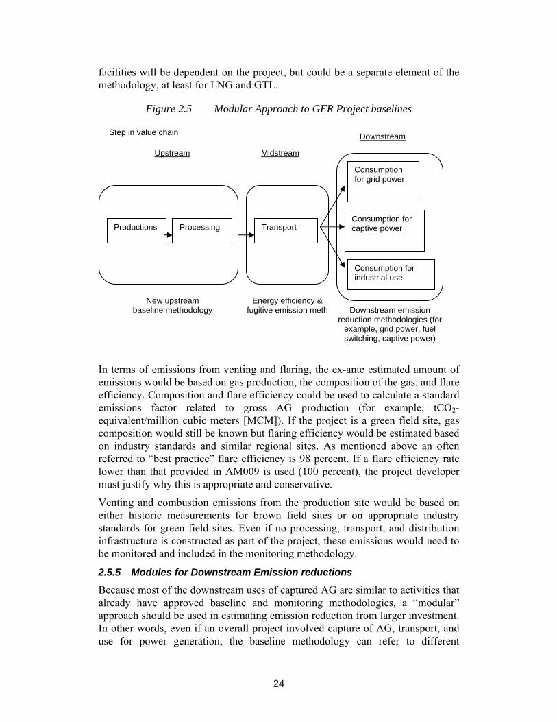
Figure 2.5 Modular Approach to GFR Project baselines
In terms of emissions from venting and flaring, the ex-ante estimated amount of emissions would be based on gas production, the composition of the gas, and flare efficiency. Composition and flare efficiency could be used to calculate a standard emissions factor related to gross AG production (for example, tCO2-equivalent/million cubic meters [MCM]). If the project is a green field site, gas composition would still be known but flaring efficiency would be estimated based on industry standards and similar regional sites. As mentioned above an often referred to “best practice” flare efficiency is 98 percent. If a flare efficiency rate lower than that provided in AM009 is used (100 percent), the project developer must justify why this is appropriate and conservative.
Venting and combustion emissions from the production site would be based on either historic measurements for brown field sites or on appropriate industry standards for green field sites. Even if no processing, transport, and distribution infrastructure is constructed as part of the project, these emissions would need to be monitored and included in the monitoring methodology.
2.5.5 Modules for Downstream Emission reductions
Because most of the downstream uses of captured AG are similar to activities that already have approved baseline and monitoring methodologies, a “modular” approach should be used in estimating emission reduction from larger investment. In other words, even if an overall project involved capture of AG, transport, and use for power generation, the baseline methodology can refer to different
Productions Processing Transport
Consumption for grid power
Consumption for captive power
Consumption for industrial use
New upstream baseline methodology
Energy efficiency & fugitive emission meth
Downstream emission
reduction methodologies (for example, grid power, fuel switching, captive power)
Step in value chain
Upstream Midstream
Downstream

25
elements from approved methodologies, for example, to establish baseline emissions factors for each step in the gas value chain. This simplifies the baseline process, because there is no need to develop completely new baseline methodologies for most of the downstream components, and project developers can draw on these modules to create a straightforward baseline scenario for many different combinations of projects. Examples of downstream modules for estimating emission reductions include the following:
• For grid-connected power generation, projects could draw from AM0005 or ACM0002, which use a combined margin methodology27 and are quite comprehensive or from the monitoring methodology for AM0010, which uses average grid emissions calculated ex post. An example of this is NM0079,28 which uses the formulas from AM0005 to set baseline emissions from grid power, even though the project activity uses gas as a fuel.
• For captive power generation, NM0079, which the Meth. Panel has recommended to the EB for approval, provides a methodology for establishing an emissions factor for captive power.
• For industrial fuel switching, AM0008 for industrial fuel switching facilities can be used for downstream fuel switching from coal or oil to gas.
• For energy efficiency of compressors, project developers could draw on the small-scale CDM rules for industrial energy efficiency to develop a stand alone baseline methodology that could be referenced in gas flaring reduction projects.29 Although developers would still need to propose a new methodology for large-scale efficiency projects, they could draw on accepted procedures for small projects as a starting point.
27 The “combined margin” approach means that both the impact of the project on current grid dispatch (“operating margin”) and the impact on the development of the power sector (“build margin”) are used to estimate the overall impact of the project on power sector emissions. For small CDM projects, for example, project developers can simply use the average of the build margin and operating margin emissions factors as their baseline emissions factor. See Practical Baseline Recommendations for Greenhouse Gas Mitigation Projects in the Electric Power Sector, 2002. Organization for Economic Cooperation and Development (OECD) and IEA Information Paper, International Energy Agency, Paris. 28 Baseline methodology for greenhouse gas reductions through waste heat recovery and utilization for power generation at cement plants. 29 See Appendix B Simplified Methodologies for Baseline Determination and Monitoring Plans for Small-Scale Projects, available at http://cdm.unfccc.int/pac/howto/SmallScalePA/index.html.

27
3 Additionality This chapter explains ways in which CDM baseline methodologies can address tools for testing additionality, with emphasis on the EB’s tool for the demonstration and assessment of additionality, as well as previous guidance on tools for additionality. The later section of the chapter includes a GFR related discussion on the various assessments for demonstrating additionality.
3.1 Additionality in Baseline Methodologies Additionality has been one of the more difficult and contentious concepts in the CDM, including its relation to projects, baseline methodologies, and baseline scenarios. Some would argue that the debate on additionality has distracted from a greater focus on developing simple and effective baseline tools. The CDM rules state that a project activity is considered additional if anthropogenic emissions of GHGs by sources are “below those, which would have occurred in the absence of the registered CDM project activity.” Developing a project’s baseline scenario therefore plays an important role in the “additionality test” of a project’s emissions. The baseline methodology must specify how this will be done. Using an approved baseline methodology does not automatically confer additionality on the project’s emission reductions, but rather provides a means for testing additionality.
In developing a baseline methodology, project developers must explain “how, through use of the methodology, it can be demonstrated that a project activity is additional and therefore not the baseline scenario.” In the PDD, however, the project developer must apply the methodology and explain why the emission reductions would not have occurred in the absence of the proposed project activity, that is, how the project is not included in the baseline scenario. The importance of addressing these two issues has been demonstrated in that five of the first eight proposed new methodologies were rejected, among other things, because they did not provide sufficient basis to establish the additionality of the projects.30
The baseline methodology must lay out the means for testing additionality when it is applied to a specific project. For example, the methodology can specify a list of questions to be addressed or contain a flow chart to demonstrate the additionality of the project or require use of the EB’s additionality tool (see below). When completing the PDD, the project developer applies the methodology including the sections pertaining to additionality. The designated operational entity (DOE) validates the assumptions used by the project developer and checks that the baseline methodology has been correctly applied, including testing for additionality.
30 NM0006 El Canada Hydroelectric Project, NM0008 Penas Blancas, NM0009 Rice Husk Power Displacement of Grid Electricity, NM0011 Bagasse biomass cogeneration, Koppa, NM0014 Rice Husk Power Displacement of Stream, NM0015 Rice Husk Power Methane Avoidance.
28
The EB is charged with the task of interpreting and applying the CDM rules including on additionality and how it is to be addressed in a baseline methodology. In October 2004, therefore, the EB released a “tool for the demonstration and assessment of additionality,” referred to here as the EB additionality tool, which may be used as part of a new baseline methodology. In developing new or revised methodologies, project developers are not required to use this tool. Project developers are free to develop their own or modify the EB additionality tool. Hence tools need not necessarily have the sequential steps of the tool issues by the EB. It should be noted that several of the already approved baseline methodologies only have one tool for assessing additionality.
3.2 The EB Additionality Tool The EB additionality tool consists of six sequential steps which project developers should follow (see Figure 3.1). The EB additionality tool flow chart illustrates that the additionality assessments are primarily sequential—in other words, projects must pass more than one kind of assessment to be considered additional.31 This is not the case for the additionality tests in many of the earlier approved baseline methodologies. In some cases, these methodologies only have one assessment, or have parallel options for assessing additionality. In addition, previous guidance from the EB listed four different alternative options for additionality testing.
The steps in the EB additionality tool include:
• Screening for projects that started prior to registration;
• Identification of alternatives to the project activity;
• Investment analysis to determine that the proposed project activity is not the most economically or financially attractive; and/or
• Barriers analysis;
• Common practice analysis; and
• Impact of registration of the proposed project activity as a CDM project activity.
3.2.1 Step 0: Projects That Started Prior to Registration
Step 0 of the tool requires proposed projects that started before registration to provide evidence that the incentives provided by the CDM were considered in the decision to proceed with the project activity. The challenge with this section is that the CDM rules only say that projects starting between 1 January 2000 and the signing of the Marrakech Accords can register as CDM project activities as long as they are submitted by 31 December 2005, and that they can receive credits for periods prior to registration (but not before 1 January 2000). In reality this is 31 For example, a project would either have to go through a regulatory screen, barriers, common practice, and impact of CDM registration, or a regulatory screen, investment analysis, common practice and impact of CDM registration, or all five tests sequentially.
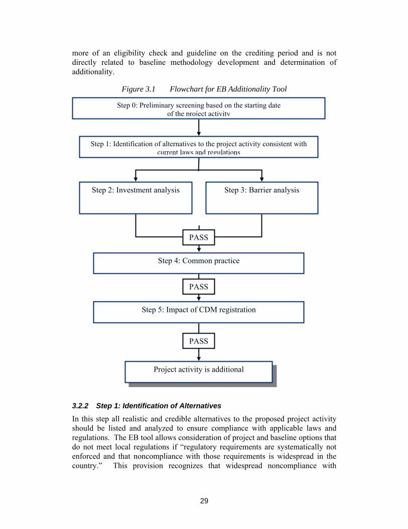
29
more of an eligibility check and guideline on the crediting period and is not directly related to baseline methodology development and determination of additionality.
Figure 3.1 Flowchart for EB Additionality Tool
3.2.2 Step 1: Identification of Alternatives
In this step all realistic and credible alternatives to the proposed project activity should be listed and analyzed to ensure compliance with applicable laws and regulations. The EB tool allows consideration of project and baseline options that do not meet local regulations if “regulatory requirements are systematically not enforced and that noncompliance with those requirements is widespread in the country.” This provision recognizes that widespread noncompliance with
Step 0: Preliminary screening based on the starting date of the project activity
Step 1: Identification of alternatives to the project activity consistent with current laws and regulations
Step 2: Investment analysis
Step 4: Common practice
Step 5: Impact of CDM registration
Project activity is additional
Step 3: Barrier analysis
PASS
PASS
PASS
30
environmental regulations is a major challenge in developing countries, and has already been included in one approved methodology (AM0012).
As stated previously, this step is also applicable to selection of the baseline scenario.
3.2.3 Step 2: Investment Analysis
For the investment analysis portion of the additionality tool, project developers have several options, depending on the nature of the project and alternatives. If the project generates no financial benefits other than CDM related income (for example, HFC destruction), then a simple cost analysis is used. Otherwise, investment comparison analysis is used for projects where the alternatives are of similar scale, and benchmark analysis is used where the scale are not similar.
The benchmark analysis is based on “standard returns in the market…but not linked to the subjective profitability expectation or risk profile of a particular project developer.” It does, however, allow the use of a “company internal benchmark (weighted average capital cost of the company); if there is only one potential project developer (for example, when the project activity upgrades an existing process).” In this case, the project developers must demonstrate that this benchmark has been consistently used in the past.
Limiting the use of internal benchmarks to this narrow case could be problematic. While in theory an external benchmark could be more objective, in practice the choice of an external benchmark will be complex and subjective, and it is not the basis upon which the developer will make an investment decision. If benchmark analysis is used, it should be based on the internal benchmark of the project developer, verified on the basis of official internal documents (for example, Board minutes, company investment policies). Proprietary information provided for this purpose should be kept confidential, and only used for purposes of validation and verification.
3.2.4 Step 3: Barrier Analysis
Project developers have the option of using either step 2 or step 3. If step 3, barrier analysis, is used the project developer must show that the proposed project activity faces barriers that prevent the implementation of the type of proposed project activity and do not prevent implementation of at least one of the alternatives identified in step 1.
3.2.5 Step 4: Common Practice
This step provides analysis of the extent to which the proposed project type (for example, technology or practice) has already diffused in the relevant sector and region. This step is a credibility check to complement investment analysis (Step 2) or barrier analysis (Step 3).
3.2.6 Step 5: Impact of CDM Registration
In this step project developers must show “how the approval and registration of the project activity as a CDM activity, and the attendant benefits and incentives

31
derived from the project activity, will alleviate the economic and financial hurdles…or other identified barriers….” To some extent, this repeats the analysis in the investment and barriers steps, since project developers must address how the project and baseline face economic or other barriers that cannot be overcome with implanting the project as a CDM project activity. In practice, evaluating the impact of the CDM on the project will be difficult, particularly ex-ante, given the complex dynamics of implementation and uncertainty on future carbon prices. More importantly, it is unclear how this test is derived from the Marrakech Accords, since the COP rejected the idea of “investment additionality” or “programmatic additionality.”32 In developing tools to address additionality, this step could be removed without compromising the integrity of the project.
3.2.7 Previous EB Guidance on Assessing Additionality
The guidance provided in the EB additionality tool, supplements previous work by the EB in which they recommended use of four distinct tools in determining additionality.33
The following options were included in the report released at the EB’s tenth meeting:
• Tool 1: A flow chart or series of questions that lead to a narrowing of potential baseline scenario options.
• Tool 2: A qualitative or quantitative assessment of different potential baseline scenarios and an indication of why the non-project is more likely.
• Tool 3: A qualitative or quantitative assessment of one or more barriers facing the proposed project activity.
• Tool 4: An indication that the project type is not common practice in the proposed area of implementation.
These tools represent four individual ways to address and justify additionality. The tools were designed to be used in concert, but in certain cases, use of only one tool could be so definitive that the other tools are not needed or relevant.
If, in developing a new methodology, project developers choose to construct an alternative additionality tool rather than the EB additionality tool, it is important to identify clearly in the baseline methodology which tool(s) will be used and how, so that each project using the methodology can then insert project-specific data and parameters into the tools to determine the additionality of the emissions related to that particular project.
32 Investment additionality was the idea that commercially viable projects can not be considered additional, which was an option in the CDM negotiating text prior to Marrakech, but was rejected in the final negotiations. Programmatic additionality means that the project would not have happened without the CDM, and was a criterion used by some national governments to screen pilot phase Activities Implemented Jointly projects, but again was not included in the MA. 33 See report from the Tenth Meeting of the EB, at http://cdm.unfccc.int/EB/Meetings.

32
3.3 Assessing Additionality for GFR Projects The following sections provide in depth discussions of various tools for determining additionality, including those included in the EB additionality tool.
3.3.1 Regulatory Requirements
The reason for assessing regulatory requirements, as well as technical feasibility, is to ensure that the project is not a priori prohibited from being additional. For gas flaring projects, this is often determined by law. If flaring is not allowed, then extinguishing the flare is obligatory and, therefore, the project is not additional. Yet even a legal prohibition can be ambiguous, particularly if it is not enforced or exemptions are granted. In some countries, flaring is prohibited but still accepted to maintain oil production, or the fines imposed are so low that flaring continues. In essence, the first tool acts to verify whether the proposed project investment is already required, either de jure or de facto.
The EB has recognized that regulations that are not enforced should not determine the baseline. In the evaluation of regulatory compliance of potential project alternatives, the EB tool states that “if the alternative does not comply with all applicable legislation and regulations, then show that, based on an examination of current practice in the country or region in which the law or regulation applies, those applicable legal or regulatory requirements are systematically not enforced and that noncompliance with those requirements is widespread in the country.” In addition, the EB has stated that policies put in place after November 2001 that support the project activity should not be considered in the baseline.34
3.3.2 Economic and Financial Assessment
Given that a project passes the first set of criteria, the issue is to determine whether a project exists that would be viable and implemented based on a normal business analysis of the project developer. While this is normally a question as to whether the project justifies investment from an economic standpoint, it can also include issues related to the project’s position relative to overall company priorities and strategies.
Economic and financial assessment has been prominent in discussions on additionality for all project types. In the case of flare reduction projects, it is often assumed that AG is flared because the economic benefits of capturing and transporting the gas to market are not sufficient to justify the investment. Factors that may provide disincentives for recovery and marketing of gas can include the following:
• High infrastructure costs
• Development costs
34 EB 16 Report, Annex 3, “Clarifications on the treatment of national and/or sectoral policies and regulations (paragraph 45 (e) of the CDM Modalities and Procedures) in determining a baseline scenario.”

33
• Limited local markets that necessitate large investments (such as LNG) to reach international markets
• Relatively small quantity or value of the gas compared with the oil
• Limited value (or different ownership) of the gas in areas that are developed as oil concessions
The implication is that the financial return in such projects is below that required by a prudent investor to justify the investment.
While financial return is important, other factors may be equally relevant in making capital allocation decisions. Companies and investors operate under capital constraints, and the estimated financial returns of such projects may not justify the diversion of capital from high-return or more strategic projects. Financial and economic measures, such as internal rate of return or net present value, are based on assumptions and the specific financial and policy regime under which the developer works. Any one measure may not provide an accurate understanding of the project’s overall economic and financial status. Therefore, care should be taken in using such measures and the assessment should be as robust as possible. For example, a developer wishing to show why a project is not in its business-as-usual scenario could demonstrate the following:
• The project is below the financial returns normally required for a project of this type and in this risk category.
• The project does not contribute significantly to the firm’s operational and strategic priorities.
• The firm’s capital limitations do not justify development of the project at this time.
Another important point is that most GFR projects will be in concession areas. In many concessions, the legal requirements are such that the only potential CDM project developers are the existing partners whose return from the project might differ substantially among one another (this is particularly true when the state is a partner or cases in which gas pipelines are owned by outside interests). Furthermore, cases exist in oil concessions in which ownership of the AG is different than that of the oil and, thus, any CDM project economics could differ among partners. This is exemplified in the most extreme case in which the AG belongs exclusively to the state and the private partners derive no benefit from its sale; the legal requirement, however, could well be that the partners must share equally in all investments.
Finally, the use of any single project economic indicator is directly influenced by the financial regime under which the project falls and the financial status of the investor. For example, AG projects in areas that have higher taxes are a priori more marginal than those in low tax areas. To the investor, the financial return of any one project is dependent on the company’s overall tax situation and its cost of raising money. Such factors suggest that any of the financial indicators used to test for additionality often will vary by location and investor. Additionally,

34
subjective but necessary assessments of geologic, political, and price risks add an additional level of complexity to investment decisions.
It is suggested that the additionality assessment related to economics should be based on a suite of economic and financial indicators that clearly demonstrate why the project would not be implemented.
3.3.3 Barrier Analysis
Barrier analysis can be thought of as those factors that are outside the direct control of the project developer and yet impact the project’s likelihood of implementation. Some of these factors can be economic, such as when the domestic gas price is controlled by the host government at a level below that needed to justify the investment in gas recovery. The fiscal regime may be designed for oil and thus provide de facto disincentives for gas recovery or even assign the ownership of the gas to a different entity than the operators of the field. A lack of access to capital may prevent project implementation (regardless of the project’s economic attractiveness).
• A proposed new technology may have higher technological and implementation risk, higher operating cost, less experience, and greater performance uncertainty than the baseline technology.
• Local market conditions, institutional weaknesses, or structural issues (for example, lack of open access to the gas transmission lines) could prevent implementation of certain projects.
• Limited information, managerial resources, organizational capacity, and so on could affect project implementation.
Barrier analysis can be a critical factor in justifying many CDM GFR projects but are, by nature, specific to the area, regime, or type of project. Thus, a methodology needs to identify and provide a general means to analyze and measure the impact of such barriers in determining the baseline scenario.
3.3.4 Common Practice
In some cases, common practice could be a major deterrent to capture and transport of AG, especially in smaller fields. A company can have a standard practice to flare AG that is small in volume or distant from the existing gas infrastructure.
Applying this tool requires documentation that common practice in the sector does not include the project type; and, in addition to the project, reference should be made to the practices of other companies.
3.4 Constructing an Additionality Tool for GFR Methodologies The methods of assessing additionality discussed above are useful and can have a place within a methodology. Many methodologies approved prior to the release of the EB additionality tool generally use more than one of these tools, and some include all four. In cases where more than one tool is used, the methodology generally indicates (a) whether answers are needed for all of the tests, (b) the

35
order in which the tools should be applied, and (c) the role of different tools in addressing various aspects of additionality.
Often, but not always, economic and financial analysis has been an important factor in demonstrating additionality since CER revenues to a project increases its economic rationale. However, it is possible to develop an additionality argument without economic analysis. The key point is: the methodology must recognize that any such test needs to cover a range of indicators and be balanced with an analysis of other barriers to project implementation.
Additionally, economic issues can play a major role in other barriers. For example, if a controlled domestic market for gas results in low gas prices, this is a market barrier with direct implications on a project’s economics. Indeed almost all the barriers, except for purely technical, have economic implications that are, or can be, addressed by economic means.35
As previously mentioned, the EB additionality tool provides scope for adapting the tool itself, as well as for the construction of alternative tools for testing additionality. Figure 3.2 below illustrates a potential alternative to the EB additionality tool based on the information presented in this chapter. It draws on the four tools provided by the EB at its tenth session. Note, however, different methodologies could use different combinations of tools, and might give different priorities or weightings, depending on the project type.
Once a set of plausible alternative project options have been identified for purposes of selecting the baseline scenario, the tools would be applied. The first tool narrows the potential baseline options considered as permissible and plausible development options for AG. Often reference is made to three sets of screening criteria: (a) regulatory requirements, (b) geophysical conditions, and (c) technological feasibility. Regulatory requirements are central in the context of GFR projects because many developing countries have stringent flaring regulations, particularly for green field projects.
The second tool is a quantitative and qualitative assessment of the plausible and permissible options identified by the first tool. In the case of a green field project, this would typically be a comparison between various options for handling the AG, such as flaring and venting, reinjection, liquefaction, or pipeline transport for downstream use. Normally, the most attractive project option, if feasible from an investor’s perspective, would be considered the most likely option and, hence, the baseline scenario. In the case of a brown field project, the comparison generally would be between continued flaring and venting and one or more of the other options identified as plausible and permissible by the first tool. In this case, ranking of options according to economic attractiveness is more complex than for green field projects because continuing “business-as-usual” activity (for example, the baseline scenario of continued flaring and venting) does not require
35 For example, the risk of a project is often offset not by reducing the risk but by requiring a higher economic return to compensate for that risk.

36
investment. Therefore, comparing the economic attractiveness of the different options may not be as straightforward as for green field projects.
Figure 3.2 Tools to Test Additionality for GFR projects Narrowing of Baseline Options
Plausible and permissible AG development options • Regulatory requirements • Technological feasibility • Geophysical conditions
Qualitative or Quantitative Assessment • Green field: compare attractiveness of investment options • Brown field: compare investment against “business-as-usual” based on a suit of
relevant economic and financial indicators Barriers Analysis
• Domestic fuel prices, risk related to local markets • Fiscal regimes, PSA, and other regulatory risks • Technological and implementation risks
Reference to Common Practice • Empirical evidence of common practice required • Not a standalone tool? * NOTE: This figure illustrates the use of these tools. However, as noted above, no specific sequence may be appropriate for all GFR project categories. (“The Greenhouse Gas Protocol: Project Quantification Standard,” developed by WRI and WBCSD, recommends that barriers analysis should be conducted before any economic and financial assessment, and the latter only be applied if the barriers analysis does not give any conclusive result.)
Quantitative and qualitative assessments may provide a definitive answer as to which option is the most likely and, hence, the baseline. For brown field projects in particular, however, further examination is often required. Options that are deemed attractive based on the second tool, for example, may in the end be unattractive and/or unlikely when barriers and common practices are considered. Tentative conclusions based on the second tool may therefore be inconclusive and necessitate the application of the third and fourth tools. Again, however, it should be stressed that, depending on the project category, one tool may be sufficient and others not relevant.
Although this section gives a description of how an alternative tool could be used in the case of GFR projects, actual baseline methodologies needs to be more specific on the key characteristics and methods for assessing additionality. The framework provided in this section is meant to help the project developer explore options for assessing additionality beyond that provided in the EB additionality tool.
3.5 Considering Country Policies The CDM rules state that baselines should take into consideration national policies of the host country. In developing new methodologies, the project developer must specify how factors such as national policy have been considered
37
(see Annex 7, section D.4 of the CDM-NBM). As noted above, national policies and, in particular, flaring regulations are also addressed in the PDD.
These considerations are particularly important for GFR projects, because many countries in the developing world have implemented laws preventing flaring, and this could make flaring reduction projects in those countries nonadditional––albeit in many countries such legislation applies only to green field projects, and, in a number of cases, legislation is not enforced or does not change operational practices.
The general consensus among experts consulted in this project is that national policies of the host country will almost certainly be considered, because considerable language exists in the CDM rules regarding national circumstances in baselines. As discussed in the GGFR Report No. 2 on the Kyoto Mechanisms, statements, commitments, and targets for flaring reductions may be incorporated into an additionality assessment. Generally, they are indicative of the baseline, but, because the types and implementation of policies can vary greatly, this does not mean that they automatically exclude a project. As stated previously, however, the EB has ruled that national policies that favor project implementation (for example, favor the reduction of flaring) that were put in place after November 2001 should not be considered in developing baseline scenarios.
Most countries have instituted direct regulations, although application and implementation differ significantly. In almost all oil-producing countries, flaring may take place only after it is authorized by a regulatory body. When authorized, flaring is subject to a variety of conditions. Emission standards and technical requirements may help to provide a concise description of the baseline conditions, so that if an investment/technology does not offer greater flaring reductions than mandatory standards do, the project is not additional.
However, direct regulation of flaring is often ambiguous; and physical, technological, and economic opportunities to avoid flaring will typically vary from site to site. Regulations may restrict flaring only where it is economically viable to do so, in which case a CDM project activity in such an area could be considered additional. While technical and economic assessments of this sort form the basis for flaring prohibition or permits, the rigor of such assessments differs greatly among countries.
It is important to judge whether national policies are binding regulations on producers or softer policy aspirations to meet certain targets. For example, it is one thing for a national government to state that it wants to progressively phase out flaring by 2008, but another for the government to make it illegal to flare after that date, with binding and enforceable consequences.
3.6 Implications of the Voluntary Standard In May 2004, GGFR partners endorsed a Global Gas Venting and Flaring Reduction Voluntary Standard. The Standard outlines a plan of action, including

38
adoption within one year of the Standard by partner companies and countries. This Voluntary Standard,36 at the outset should not influence the baseline for flare reduction activities. It is a process not a fixed target and should be seen as an aspiration, a means to achieve reduction and, eventually, elimination of flaring. One way to achieve this aspiration is to use the CDM. The CDM can make an important contribution to stimulating investments in flaring reductions; hence, it can also make an important contribution to objectives of the GGFR Voluntary Standard. When relevant, project developers can reference the Standard in the baseline methodology and clarify how it relates to the additionality assessment.
36 GGFR Report No. 4, A Voluntary Standard for Global Gas Flaring and Venting Reduction, May 2004.

39
4 Project Boundary and Leakage This section explains how to set the project boundary and related leakage issues for GFR projects and recommends how these can be best addressed in baseline methodologies. Leakage is defined as the net change of GHG, which occurs outside the project boundary and which is measurable and attributable to the CDM project activity. Project boundary and leakage are interrelated because emissions outside the project boundary that are directly influenced by the project are considered leakage and must be identified. These issues are addressed primarily in sections 4.5 and 4.8 of CDM-NMB.
4.1 How to Determine the Project Boundary 4.1.1 Principles
Project boundaries for CDM projects must be determined on a project specific basis. In order to accomplish this, the baseline methodology must specify the process and principles to be applied in determining the boundaries for the category of projects covered by the methodology. According to the CDM rules, the project boundary should include all GHG emissions that are:
• Under the control of the project developers—implies direct control or influence, including, where appropriate, the scope of Production Sharing Agreements.
• Significant—determined as significant if they can be calculated with a reasonable level of accuracy (for example, to be more than 1 percent of the total emissions/emission reductions of the project).37
• Reasonably attributable to the GFR project activity—closely linked to “under the control of…,” and project developers may wish to consider the boundary of the gas infrastructure or investment made for the GFR component, or the capture, transport, and utilization of the AG.38
When applying these principles, the key issue to consider is the extent to which project partners control different stages of the gas value chain. The following subsections apply these principles to different project types.
37 This is a rule of thumb used by the Dutch Certified Emission Reduction Unit Procurement Tender (CERUPT/ERUPT) guidelines, and this rule is included in one of the approved methodologies (NM0021 CERUPT methodology for landfill gas recovery). Some of the concerns pointed out in this section may, in the end, not be deemed material to the project and, thus, not pass a significance test. As the CDM process develops, more guidance should be forthcoming on what constitutes appropriate project boundaries. 38 These points are based on Decision 17/CP.7, Draft decision article, Section G, paragraph 52. The EB stated in its fifth meeting that it would develop further guidance on the terms of “under the control of,” “significant,” and “reasonably attributable.” At the time of writing, this guidance has not yet been published.

40
4.1.2 Project Types
In the GFR project categories considered in this report, upstream activities, including processing, are assumed to be under the control of the project. Upstream activities are normally key components for GFR projects and give the largest emission reductions. In addition, any transport and distribution infrastructures that are constructed for the project may also be significant components of the project.
For reinjection projects, the project boundary would include the production site and any processing facilities. As a result of the review process for AM0009, onsite fugitive emissions of that methodology were included within the project boundary.
For projects that capture and transport gas for end-use consumption, the transport and distribution infrastructure may be included within the boundary, but whether the end-use site is included will depend on the contractual arrangements among the owners of different parts of the gas value chain. AM0009 requires that fugitive emissions from the pipeline and compressor combustion emissions be included in the boundary. In the case of the Rang Dong project, on which AM0009 is derived, these emissions while small were judged to be under the control of the project developers and directly attributable to the project activity.39
To determine whether to include the end-user site within the project boundary, the following questions should be asked:
• Are project partners for the upstream project also the investors in the downstream activities?
• Do the contractual arrangements between the end user and gas supplier give the supplier the right to monitor the use of the gas (so it can be attributed to the project) and right to the CERs that result from the emission reductions at the end-use site?
• Is the gas supplied to a single dedicated point of end use, in which case the end user could possibly be included within the boundary?
If any one of these questions is answered in the affirmative, then the end-use site may be included in the project boundary. In the case of the first question, it is because the project partners own at least part of the whole value chain, and thus the emissions from that chain are under their control. In the case of the second, monitoring the impact of the gas means that the project developers can justify that the emission reductions are attributable to the CDM project activity. The third question determines whether the emission reductions can be attributed to the project with certainty, although some form of monitoring would be needed in this case. If the gas is discharged into a pipeline network that feeds multiple end users and has multiple sources, then it is more difficult to attribute changes at these various sites to the CDM project activity.
39 The transport infrastructure for Rang Dong was built specifically for this project.

41
The first two questions also identify who is considered a “participant” (or developer) in the project. The official CDM glossary defines project participants as, “parties or private and/or public entities that take decisions on the allocation of CERs from the project activity under consideration.” This means that national law on allocation of CERs and contractual arrangements regarding CER ownership are key determinants of who is a project partner and in setting the project boundary.
Capture and processing of liquids is treated similarly to any other project that supplies gas for end-use consumption. The project boundary may include the production site, processing, and loading onto a tanker. These activities are normally all under the control of the project developer. To determine whether the end user of the liquids should be included in the project boundary, the project developer would ask the three questions listed above.
4.1.3 Multi-country Projects
A project may cross borders and cover more than one country (for example, capture of gas in one country and use of it in a neighboring country). For example, the West African Gas Pipeline project’s flaring reductions occur in Nigeria, whereas fuel switching from diesel to natural gas for power generation due to the project could be achieved in Benin, Togo, and Ghana.40 In this case, arguably the project boundary should comprise the relevant project sites in all of the countries involved, to encompass all of the affected emissions sources. The same would be true of a project that uses the AG for grid power generation, but this power generation displaces imports of electricity, not domestic generation.
For project developers to be able to claim the emission reductions for the entire project, one issue that must be addressed is the role of Designated National Authorities (DNAs) in approving multi-country projects, and whether national sovereignty would be a barrier to claiming these credits. A second issue is how to decide who should appear as project participants for purposes of receiving CERs.
In many cases, a potential multi-country project could also be submitted as individual projects, with separate DNAs given the responsible for approving the component within their national borders. This may be easier, because it would not require negotiations among countries about credit ownership and would simplify the legal and contractual process––and the project developers would still earn all of their credits.
4.2 How to Determine Leakage The question of leakage is closely linked to the definition of the project boundary. Leakage is defined in the CDM rules as “the net change of anthropogenic emissions by sources of greenhouse gases (GHG) which occurs outside the project boundary, and which is measurable and attributable to the CDM project activity.” As previously noted, in the CDM, leakage does not refer to physical 40 A short description of West African Gas Pipeline as a GFR project can be found in GGFR Report No. 2 Kyoto Mechanisms for Flaring Reductions.

42
leakage (for example, fugitive emissions from pipelines) but rather impacts on GHG emissions that are outside the defined project boundary.
If an upstream GFR project affects emissions downstream, this could constitute leakage. In practice, this is unlikely to be common, because in cases where it is possible to measure downstream impacts, the project developers are likely to include the end-use site in the project boundary; thus, these emission reductions will not be leakage since they will be covered in the project boundary.
If the downstream emissions cannot be quantified, then changes in emissions, while outside of the project boundary, are not “measurable and attributable” and, therefore, cannot be counted as leakage. For example, if the gas captured goes into a pipeline that has multiple sources and multiple users, then the impact of the gas on end-use emissions is not quantifiable. This, therefore, could not be treated as leakage.
One leakage issue for GFR projects raised by some stakeholders is the impact of reinjection on current oil production (through enhanced oil recovery) and future/postponed production of gas. It is unlikely that these increases in production are measurable and can be attributed to the project as leakage.
In terms of local market impacts, project developers should demonstrate that gas from the project is not significant enough to affect local market prices and demand by showing that the increase in gas availability is not significant and will not change the supply-demand balance. Information provided by the Rang Dong project developers in response to Meth. Panel comments, for example, demonstrated––through comparison with local demand––that the supply of gas products from the project was insufficient to impact price or consumption.
Fugitive emissions along the transport system, including emissions from LNG tankers, may be considered as a potential leakage. The question is whether these emissions can be measured and whether they are attributable to the project activity. For example, if initial calculations show that these emissions are more than 1 percent of total project emissions they should be estimated as leakage. Several proposed methodologies have used this 1 percent significant rule.
Gas deliveries into the international market or integrated pipeline networks with no dedicated gas user would normally be outside the project boundary. These also would not be considered leakage because it would not be possible to measure the impact of an individual input on consumption demand patterns of the overall market. Whether standard leakage rates from these pipeline systems would need to be considered when calculating the net impact of flaring reduction projects is not clear, but this most likely would depend on whether the captured gas affected the overall volume transported by the pipeline and whether the pipeline operated within international norms concerning losses.

43
5 Data and Monitoring The purpose of this section is to identify the data and monitoring key parameters and issues for GFR methodologies.
5.1 Key Parameters Sections 4.6 and 4.7 of CDM-NBM require that the project developer elaborate and justify all of the formulas, algorithms, variables, and parameters that are used in the baseline methodology, while section 5 should contain specific data and assumptions used. Any standard values should be reported here.
For GFR projects, AG production is the key variable in terms of assessing mitigation potential. Because AG production levels and characteristics can change over time, all of the methodologies should lead to some form of standardized, or rate-based, baselines. This means that baseline emissions would be related to activity level (that is, production). For example, emissions from flaring AG could be expressed as tCO2/MCM of gas production. Setting a standard emission factor for the baseline means that the credits awarded to the project can be adjusted based on actual gas production, so any uncertainty in ex-ante production projections will not affect the actual number of CERs issued.
If the baseline emissions factor is fixed, project monitoring should establish project emissions per MCM of gas production. The product of the difference between these two emissions factors and actual measured gas production gives the number of CERs. Other standardized measures for the baseline could include emissions from pipeline systems (tCO2/kilometer [km]) and compressor stations (tCO2/megawatt [MW]), as well as emissions from LNG processing (tCO2/MCM of gas processed) within the designated monitoring period.41
The gross carbon emissions for a given AG production site and the investment required are known with relatively high certainty. The emission projections are based on the forecasted oil production, the gas-to-oil ratio, and the flaring efficiency. The first two factors are based on historic production (or well tests) and the reservoir models, while the last factor is based on gas composition and estimated efficiency.
Other key parameters include fractional composition of AG before combustion (for example, proportion of methane [CH4], CO2, and other hydrocarbons, accurately quantified and usually expressed as a percentage).
5.2 Data Sources and Availability Section 5 of the CDM-NBM covers the data sources and assumptions that should be used in the baseline methodology.
41 For more examples, see Table 13 in the IEA report Emission Reduction in the Natural Gas Sector through Project-Based Mechanisms, 2003, at: http://www.iea.org/dbtw-wpd/textbase/papers/2003/devbase.pdf.

44
For baseline emissions, data availability and standards used are particularly important issues for green field projects, since brown field projects normally will have existing data. The baseline scenario will need to forecast the emissions at various stages of the gas chain, based on relevant comparisons in the region or internationally. As discussed in section 2.5.1 of this document, fugitive emissions can occur at each stage along the gas value chain, because of leaks, venting during maintenance, and the use of gas in pneumatic devices. National regulations may specify what levels of fugitive gas are acceptable, in which case these will be useful for constructing the baseline. If national regulations do not exist, then regional or international standards can be used (see examples in the International Energy Agency [IEA] report Emission Reduction in the Natural Gas Sector through Project-Based Mechanisms).
After projects are implemented, the monitoring plan will include quantification of fugitive emissions and compressor/on-site energy use. The project developer should conservatively estimate these factors/standards using established factors and practices (for examples, compressor energy use). It is important to remember that, in most cases, gas is monitored along the value chain, and therefore, limited additional project monitoring is required for a CDM project.
5.3 Uncertainties Section 6 of the CDM-NBM covers uncertainties in the baseline methodology. Uncertainties for GFR projects relate both to the assessment of additionality (for example, the accuracy of the barrier assessment or economic analysis of alternatives) and the main parameters and assumptions outlined above. These assumptions include quantity of AG; fractional composition of the gas, which is directly measurable using commercially available metering equipment; and emissions from energy consumption for compressors and processing facilities. The uncertainties are managed insofar as emission reductions are accrued only for actual gas recovered and used (for example, gas delivered to the power plant).
5.4 Transparency and Conservatism Section 7 of the CDM-NBM requires a description of how the baseline methodology was developed in a transparent and conservative manner. The transparency requirement is best met by ensuring that the methodology is logical; fully documented; and, to the degree possible, developed using established factors, algorithms, and protocols. Where possible, approved methodologies, either in whole or in part, should be used to construct proposed or revised methodologies. The methodology should also require the project developer to clearly cite all reference documents, such as oil field development plans or protocols.
The issue of conservatism is crucial both in the calculation of GHG baseline emissions and the justification of the additionality of the project. Concerning emissions, the implication is that all of the relevant emissions impacts (positive and negative) should be fully incorporated and, when uncertainty exists in the factors used for calculating emissions, the one providing the lowest emission

45
reductions must be used. In AM0009, for example, a measure of conservatism was the assumption that all CH4 would be converted to CO2, thus having the impact of lowering the baseline emission scenario.42
Concerning the assessment of economic attractiveness, fuel prices and other variables should be consistent with the firm’s policy, because these are important for the project’s economic attractiveness. Any risk premium incorporated into the economic analysis, or anywhere else within the evaluation, should be clearly identified, quantified, and justified.
When applying an approved methodology to a specific project, the project developer should bear in mind that assumptions, statements, algorithms, or data will be subject to validation by an independent third party.
5.5 Monitoring Methodology Elements While the focus on this report is on baseline methodologies for GFR projects, the EB has stated that monitoring methodologies must accompany new baseline methodologies, because both are used in combination to calculate emission reductions. The CDM-NMM form (new monitoring methodology form) is contained in Annex 8 of this report. The main areas covered include:
• A brief description of new methodology.
• Data to be collected or used to monitor emissions from the project activity, and how these data will be archived.
• Potential sources of emissions, which are significant and reasonably attributable to the project activity, but which are not included in the project boundary and identification of whether and how data will be collected and archived on these emission sources.
• Assumptions used in elaborating the new methodology.
• Quality control (QC) and quality assurance (QA) procedures are being undertaken for the items monitored.
• The potential strengths and weaknesses of this methodology.
• Whether the methodology has been applied successfully elsewhere and, if so, in which circumstances.
The CDM–NMM includes tables to indicate data to be monitored, how it will be collected and archived, and what QC procedures will be applied to each process.
As with baseline methodologies for upstream elements of GFR projects, downstream elements of these projects can draw on existing monitoring methodologies developed for end-use of the gas. Each major step in the value chain would have its own set of parameters that should be monitored, which 42 The methodology recognizes that some gas would be uncombusted, that is, up to 2 percent released into the atmosphere, but argues that, because of difficulties in measuring this, it should be assumed that all methane would be flared in the interest of conservatism.

46
would make it relatively simple for a project developer to put together their monitoring plan for the overall gas flaring reduction project. For upstream elements, key data to be monitored would be as follows: AG captured, gas composition, flaring efficiency (if there is any emergency flaring in the project case), fugitive emissions on site and during processing, and gas consumption for energy use on site.43 Gas use for energy in compressors and processing can be calculated indirectly from the difference in gas production and gas export from the processing site. The monitoring protocol should specify where along the gas chain the flow of gas would be measured, and the data should then be used to estimate gas utilized for energy in production and processing.
For pipeline transport, monitoring will occur in any case to ensure the safety and integrity of the pipeline network.
This monitoring plan should be part of the PDD.
43 For the Rang Dong project, the project developers argued that fugitive emissions on site and during processing would be negligible because of safety concerns and local regulations.

47
Annex 1 CDM Primer A.1.1 The CDM after Marrakech The clean development mechanism (CDM) is one of three market-based mechanisms established in the Kyoto Protocol to assist Annex I44 countries in meeting greenhouse gas (GHG) emission reduction and limitation targets.45 It enables project developers and investors to earn credits (certified emission reduction units [CERs]), which can be used against domestic emission reduction targets46 (now or in subsequent or other defined future commitment period), or sold in various carbon markets.
The CDM became operational following the conclusion of the seventh session of the Conference of the Parties (COP-7) to the United Nations Framework Convention on Climate Change (UNFCCC). It was at COP-7 that the majority of rules and procedures for the CDM were adopted as contained in Decision 17/CP.7 of the Marrakech Accords. In this report, the term “CDM rules” encompasses the CDM modalities and procedures47 and any guidance issued by the CDM Executive Board (EB), the COP and COP/MOP.
The EB held its first meeting following COP-7. It is required to meet at least three times per year. As of March 2005, the EB has held 18 meetings in which they have approved methodologies, registered projects, issued guidance on various issues, and established advisory panels to assist it in accomplishing its goals. Three panels have been established: (a) a the small-scale panel, responsible for recommending modalities and procedures for small CDM projects (this panel has since completed its work);48 (b) the accreditation panel, responsible for setting up the accreditation system and for recommending accreditation of entities as operational entities (the first step in becoming a designated operational entity [DOE]); and (c) the baseline and monitoring methodology panel (referred to as the Meth. Panel), responsible for providing recommendations to the EB on baseline and monitoring methodologies, among other issues. In addition, an
44 Annex I countries are defined as countries that have signed the Kyoto Protocol. A list of these countries can be found at: http://unfccc.int/resource/conv/ratlist.pdf. 45 For a more thorough introduction of the CDM, please see GGFR report on Kyoto Mechanisms for Flaring Reduction available at http://www.worldbank.org/ogmc/ggfr. For detailed information, the reader is referred to the UNFCCC CDM website at http://cdm.unfccc.int/. 46 Validity of CERs within a domestic emissions trading schemes (ETS) will be dependent on the scheme’s design. For instance, the European Union (EU) will allow CERs into its ETS, but may impose limits. Clearly, the value of a CER is likely to be higher if it can be used in a domestic or regional ETS than if the CERs cannot enter into any established systems. 47 In many reports, the term Marrakech Accords is used to refer to the CDM modalities and procedures. Strictly speaking, the Marrakech Accords, however, encompasses 24 Decisions taken by the COP covering a range of issues, many of which have no relation to the CDM. 48 The three main project types are (a) projects that do not exceed 15 megawatts (MW) of nominal capacity, (b) EE [Energy Efficiency] projects that do not save more than 15 GWh per year, and projects that do not directly emit more than 15,000 tCO2e annually.

48
expert Working Group on Afforestation and Reforestation and on Small Scale Project Activities has also been established.
With implementation of the European Unions Emissions Trading Scheme from 1 January 2005 and the Kyoto Protocol in force from 16 February 2005 the CDM can now be applied broadly as a compliance tool for meeting Kyoto Protocol obligations.
A.1.2 The CDM Project Cycle Typical steps in the CDM project cycle are as follows (see Figure A.1.1):
• Project identification and design: The project owner/project developer identifies an opportunity, conducts a prefeasibility study, and develops a CDM Project Design Document (PDD).
• Host country approval: The designated national authority (DNA) of the host country approves “voluntary participation” of the project. This approval is generally based domestic requirements for CDM projects such as a country’s evaluation criteria and its assessment of the project’s contribution to sustainable development.
• Third-party validation of project design and baseline: The PDD is validated by a DOE that serves as an independent third-party auditor.
• Registration: Once a project is validated by a DOE and approved by the host country, it is considered for registration by the EB.
• Financing and implementation: The project is financed and implemented like a normal investment project.
• Monitoring: Project performance, including baseline conditions, is measured by the project developer in the commissioning process and throughout the crediting lifetime of the project, to calculate the actual emission reductions.
• Verification of project performance: The DOE verifies project performance, against the validated design and baseline, to certify the credits.
• Issuance: Based on the successful performance of these steps, CERs are issued by the EB in accordance with the verification report and distributed in accordance with the agreement between project participants.

49
Figure A.1.1 Steps in the CDM Project Cycle
Project design document
Host country approval Designatednational authority
Operational entities
Project owner
Executive Board
Validation
Registration
Financing & implementation
Monitoring
Verification & certification
Issue CERs
Selecting a baseline methodology relates to the first step of the CDM project cycle. Other activities in this step include (a) designing the CDM project (or, if it is a subset of a larger project, defining the CDM portion of the project), (b) reviewing host country regulations, (c) developing a baseline scenario and monitoring plan, and (d) soliciting stakeholder comments.
Project developers must choose an approved methodology. If an appropriate methodology does not exist for a specific project type, then project developers must develop one based on it proposed CDM project activity. The CDM rules require that, at a minimum, a draft Project Design Document (PDD) be submitted to the EB for approval of a new methodology. A draft PDD differs from a complete PDD in that an environmental assessment, stakeholder comments, and host country approval are not required. Project developers have generally submitted full or almost complete PDDs
A.1.3 Methodology Approval Process
The EB set up a process to evaluate baseline methodologies within the four month time frame required under the CDM rules. During this time, the Meth. Panel

50
evaluates the methodology, including on the basis of inputs by expert desk reviewers, and provides recommendations to the EB. The EB takes decisions on the methodologies by approving the methodology, rejecting it or requesting revisions.49 Rejection of a methodology, however, does not mean that the project has been rejected. Those methodologies can in fact be revised and resubmitted for approval. The EB generally requests project developers to do so in their recommendations.
In practice the four month time frame would have meant approving or rejecting methodologies outright. In order to enable more methodologies to be approved, the EB expanded the process to include revisions and feedback loops, thereby potentially increasing the time required for methodology approval. While a few of the approved methodologies have taken four months or less to approve, most have taken longer. Six to seven months has been more typical, with some methodologies taking more than a year to be approved. Part of this is due to the newness of the process, and it may take some time to implement an efficient system of evaluation. Recent rejections have taken roughly five months, although there are examples of longer process times. Of the “B” cases of methodologies under consideration, three methodologies were submitted more than a year ago and another eight that have been under review for nine months. It is unclear, however, whether this is due to the EB process or whether the project developers have chosen to delay or suspend the process.
The EB agreed on a process for reviewing and approving new methodologies, which is shown in Figure A.1.2.
49 EB recommendations on methodologies are A=approved, B=revisions requested, and C=rejected. Even C category methodologies, however, can be revised and submitted again. In fact, the EB requests project developers to do so in their recommendations.

51
Figure A.1.2 Steps in the Process of Methodology Approval

53
Annex 2 GFR and the CDM A.2.1 Key Features of GFR Projects Associated gas (AG)50 is a blend of various hydrocarbons that are released when crude oil is brought to the surface. The composition and amount of such gases varies from one field to another. AG combusted or released as un-combusted gas produce the primary greenhouse gases (GHG), carbon dioxide (CO2), and methane (CH4).51 The ratio of combusted to uncombusted gas is crucial because the impact of CH4 on global warming is greater than that of CO2. Therefore, a small change in the ratio of flaring to venting has a disproportionate change in the impact on the global environment.
A flare reduction project typically reduces GHG emissions by one or more of the following development options for AG that is currently or expected to be flared:
• Capture and reinjecting the gas into the oil reservoir,
• Capture and delivery through a pipeline to an end user, and
• Capture and process the gas into liquids (that is, liquefied natural gas [LNG], gas-to-liquids [GTL], or liquefied petroleum gas [LPG]) that can be transported and sold locally or internationally.
In general, choosing the appropriate option(s) depends on upstream conditions, such as field characteristics and the oil-to-gas ratio, downstream market opportunities for the recovered gas, and the legal and fiscal frameworks that may include various incentives and penalties. Understanding and documenting how these factors influence decisions made by the petroleum industry are critical for the CDM to become an effective instrument that supports the objectives of the Kyoto Protocol and the UNFCCC.
A.2.2 The Gas Value Chain
Disaggregation of the gas value chain for the purposes of baseline methodology development is useful and appropriate, because it reflects industry practice (that is, a closed chain of activities involving distinct processes, often under the control of different actors and stakeholders) and the nature of emission reductions in each stage are materially different. This annex and the next describe each step of the gas chain, and the emissions that occur in each stage.52 Because the focus is on
50 Sometimes called solution gas. 51 Flaring and venting of AG also give rise to relatively small quantities of nitrous oxide (N2O) emissions, also listed as a GHG and covered by the emission targets of the Kyoto Protocol. 52 This section of the annex is adapted from "Developing Baselines for Natural Gas Projects" published by the IEA (www.iea.org). An additional source of information on the identification and evaluation of GHG emissions and the reporting of these is the Petroleum Industry Guidelines for Reporting GHG Emissions available at http://www.ipieca.org/working_groups/climate_change/cc_home.html.

54
AG from oil production, issues that relate only to dedicated natural gas production are not discussed.
Extraction/production: Oil reserves are identified through a combination of seismic analysis and remote sensing technology, after which exploratory wells are drilled to evaluate the quality and quantity of reserves. Even where the wells are drilled primarily for oil production, the AG exits the well under high pressure. In the past, because the focus was solely on crude oil extraction, the natural AG from these wells was often flared or vented into the atmosphere.
Processing: While gas from some fields meets the quality conditions necessary for transport through a pipeline, generally AG must be processed before it can be used. Gas processing removes the water and any acidic substances such as hydrogen sulfide (H2S) and/or CO2. In addition, if heavier hydrocarbons are present in the gas (such as ethane, propane, butane, and/or pentane), they must be processed before transporting the dry gas by pipeline. These heavier hydrocarbons are referred to as natural gas liquids once they are removed from the gas stream.
Pipeline transmission: After processing, gas may be used on site (for example, for power generation), reinjected, transported to market via a pipeline, or liquefied and transported in a tanker by sea. The decision on transmission mode is based on the economics of transport, because pipelines require a large capital investment to cover significant distances. Pipeline systems include compressor stations to efficiently move gas through the pipelines, as well as period valves used to close off sections for maintenance and repairs. Depending on the distance from the market, the cost of pipeline infrastructure can often be a major barrier to marketing gas.
LNG: For long distances, gas can be liquefied, put into tankers, and then vaporized at the destination port. LNG liquefaction, transport, and re-gasification are separate procedures logistically and geographically, often operated by separate companies. The process requires a large investment in port facilities, and, thus, is done only when large quantities of gas are involved. A number of different processes can be used to vaporize the gas at the destination before it is charged into a pipeline network.
Storage: Storage facilities are used at many stages of the gas chain to balance supply and demand in the gas market. Facilities include geologic storage in aquifers, depleted oil fields, and salt caverns, as well as dedicated LNG storage facilities.
Distribution: Local gas distribution companies take the gas from pipelines, reduce the pressure, add an odorant, and move the gas into a smaller diameter pipeline system for local end users.
End-use consumption: Gas is a versatile fuel that can be used for power generation, industrial boilers and process heat, commercial and residential heating, cooling, and cooking, and even as a transport fuel. Other end-use applications are gas as feedstock in the chemical industry and GTL processes.

55
Figure A.2.1 provides an overview of the facilities and processes to take produced gas to market.
Figure A.2.1 Overview of Upstream and Midstream Gas Industry
Source: International Energy Agency. 2003. “Developing Baselines for Natural Gas Projects.” A.2.3 GHG Emissions along the Gas Value Chain
There are basically three categories of GHG emissions along the gas value chain: vented gas, fugitive emissions, and emissions from combustion for energy use. These emissions are summarized in Table A.3.1. Venting occurs when AG from the oil wells is released directly into the atmosphere as CH4. Given that CH4 is more potent as a GHG than carbon CO2, even a small amount of venting has a major impact on climate change. Even if the AG is routinely flared, not all will be combusted and converted to CO2: a fraction will be vented. International studies suggest that best-practice efficiency of combustion is 98 percent, which means that 2 percent of the gas would be released as CH4. It should, however, be noted

56
that actual flare efficiency can vary substantially, depending largely on gas composition and wind speeds.53
Fugitive emissions refer to unintentional emissions from leaky valves, loose dry seals in compressors, flanges, and/or intentional venting away from the production site. Gas is normally vented to prevent a dangerous build up of pressure in the system, or to release gas to undertake maintenance on a section of the system. Gas is often emitted during the decompression of equipment, before maintenance, to help ensure a safe working environment during repair activities. Typically, operators will block the smallest segment of pipeline needed to make the repair and vent the contained CH4 into the atmosphere. An alternative to this direct CH4 release is to capture, recompress, and reinject the gas back into the system. In addition, pneumatic devices are often powered by pressurized natural gas and are used as liquid level and valve controllers, as well as pressure and temperature regulators. Gas-powered devices such as this “bleed” CH4 emissions. Fugitive emissions also occur during loading and unloading of LNG into ships.
The equipment that drives the gas production, processing, and transport system is generally powered by a portion of the gas produced, so the operation of this equipment leads to CO2 emissions. Onsite equipment for extraction, compressors, and processing facilities all burn gas for energy. In the production of LNG, liquefaction requires significant amounts of energy as well.
The focus of this report is on mitigation projects whose primary aim is to eliminate or reduce flaring and venting of associated gas. These projects will reduce emissions at the production site, but they could actually increase emissions in processing, transport, and distribution if these facilities are not present in the baseline. At a site where all AG is flared and there is no equipment for processing, there cannot be any fugitive emissions from processing. Of course, projects that collect, process, and market the gas will result in downstream emission reductions as well. The net carbon reductions are estimated (or measured), thus, the carbon emission from gas that is marketed instead of flared will be the sum of carbon reductions at the wellhead minus any losses along the chain, plus the reductions from end-use fuel switching. It is important to quantify the net carbon emission changes from production to burner tip.
The mitigation options for each stage of the gas chain are summarized in Table A.2.1.
53 See The Flare Research project at the University of Alberta at http://www.mece.ualberta.ca/groups/combustion/flare/index.html.

57
Table A.2.1 Summary of Emissions Sources and Emission reductions Opportunities at Each Stage of the Gas Chain
Stage of the Gas Chain Nature of Emissions Opportunities for Emission
Reductions Natural Gas Extraction and Production
Venting and flaring of associated gas Emissions from on-site energy use Fugitive CH4 emissions from production facilities and gathering lines
Reinjection of associated gas Improve energy efficiency of operations; convert from higher to lower carbon fuels (for example, oil to gas). Eliminate venting or enhance flaring efficiency (increase proportion of methane converted to CO2) Capture of AG and use on site or downstream
Processing Fugitive CH4 emissions from the following: • Treating gas to remove
liquids and other gases • Compressor use in pipelines
and LNG liquefaction and re-gasification
• Maintenance Energy use emissions from processing plant, including liquefaction
During maintenance, capture, recompress, and reinject the gas into the system Enhance energy efficiency in compressors to reduce fuel consumption (for example, replacement of compressors, or components such as wet seals with dry seals and compressor rod and ring replacement) Waste heat recovery and use of high-efficiency turbines
Transmission and Storage
Fugitive CH4 losses from the following: • Compressor use in pipeline
transportation • Leaks in pipelines • Tanker loading and
unloading • Gas not recaptured in LNG
boil off • Maintenance Energy use emissions in transport
Reduce fugitive emissions by replacing compressor components, installing vapor locks on tanker loading, and capturing and reinjecting gas during maintenance Enhancing energy efficiency in compressors to reduce fuel consumption (see above)
Distribution Fugitive emissions from pipelines, meters, pneumatic devices, and maintenance
Replacement of gas-fired pneumatic devices with compressed air systems or other “low-bleed devices”
Consumption Energy use emissions from power sector, commercial and industrial, or domestic use
Fuel switching to less carbon-intensive fuels Domestic uses displace unsustainably forested (traditional) biomass


59
Annex 3 Modules for Downstream Emission reductions
A.3.1 Grid-Connected Electricity Generation A.3.1.1 Introduction
This is an example of a methodology from which elements may be drawn upon to calculate the baseline emissions factors for a grid connected power generation component of a gas flaring reduction (GFR) project activity. The approved methodology uses the “combined margin” approach to establish a baseline emissions factor for a grid-connected power project.54
The methodology is applicable in cases where the following occurs:
• There is sufficient publicly available information on the nature of the barriers and the common practice in the sector,
• The project supplies a grid whose geographic and system boundaries are well known and information is available on its characteristics,
• The grid is not dominated by zero- or low-cost generating sources (hydro, geothermal, wind, solar, nuclear, and low-cost biomass).
A.3.1.2 Background to the Methodology
When considering the emission reductions gained from downstream activities, such as consumption of gas by power stations, a standardized baseline approach may be required for the electric power sector, taking into account regional, national, or subnational circumstances. Simply expressed, these are benchmarks in the form of emissions rate per unit of activity (for example, kilograms carbon dioxide per kilowatt hour).
The method used in the approved baseline methodologies for grid connected power is based on recommendations for baseline methodologies developed by the Organization for Economic Cooperation and Development (OECD)/International Energy Agency (IEA).55 These are based on a model of the electricity sector as a whole in that country and an understanding of the project activity within that generating mix. An electric power grid usually has different types of power plants that are operated simultaneously, including thermal plants (coal, gas, and oil), hydroelectric, nuclear, renewables, and so on. Some are operated as baseload 54 Based on AM0005, Barrier analysis, baseline scenario development, and baseline emission rate calculation for a proposed grid-connected project that displaces power from the operation and expansion of the electric sector, and ACM0002, “Consolidated baseline methodology for grid-connected electricity generation from renewable sources”, both available at http://cdm.unfccc.int/methodologies. 55 See Practical Baseline Recommendations for Greenhouse Gas Mitigation Projects in the Electric Power Sector, 2002. OECD and IEA Information Paper, International Energy Agency, Paris.

60
power plants at a high capacity factor, and others as intermediate and peaking plants, depending on economics and availability. Thus, establishing a baseline for a CDM electricity project requires determining how that project affects the operation and/or future construction of other plants on an interconnected grid.
Simple models include calculating average emission rates, which uses an overly simplistic assumption that the project activity displaces a proportion of all plants on the grid. Others exclude nuclear, hydro, or other renewable plants, because of their low operating costs or because it is not possible to shift the hours of generation. Another approach is to use marginal plant only, assuming that those running at highest cost will be displaced first. It requires modeling of the generation of each plant for each hour in a year to determine what is being displaced and, hence, an hourly emissions rate. This approach, while most accurate, is subject to a lack of sufficient data in many developing country contexts.
A.3.1.3 Calculating the Baseline Emissions Rate
The approved methodologies use a combined margin methodology for most grid-connected projects, where the counterfactual scenario is the ongoing expansion and operation of the overall grid. This approach reflects the fact that grid connected projects are likely to both affect the operation of current or future plants as well as the building of new facilities. The approach is a weighted average of the emissions in metric tons of carbon dioxide per megawatt hour (CO2/MWh) of the following:
• Operating margin (assuming that the project activity affects the operation of existing plants on the grid in the short term)
• Build margin (assuming that the project activity will delay or replace the construction of a new plant in the long term).
The operating margin reflects the project’s impact on the operation of the existing plant. Ideally, this would be based on detailed information about the last plants to be dispatched to meet demand at any time, including historic dispatch data, the hourly cost of different plants, and so on. Because much of this information is difficult to obtain in the developing country context,56 a proxy is used. The proxy is a weighted average of all plants in operation on the grid, excluding “must run” plants and those that have zero-cost fuels (hydro, geothermal, wind, low-cost biomass, for example, sugar cane bagasse and paper and pulp residues). In situations where hydro is a major component of the generating mix, an adjustment is required.
The build margin attempts to predict the type of generating facility that would have been built in the absence of the CDM project. Even if the project does not displace new plant additions, it is likely to delay them, affecting all new 56 For their application to the developing country context in Chile, South Africa, and Brazil, see Road Testing Baselines for Greenhouse Gas Mitigation Projects in the Electric Power Sector, 2002. OECD and IEA Information Paper, International Energy Agency, Paris.

61
prospective capacity. The methodology should reflect all plant types being added to the grid system, based on the recent and ongoing power plant construction activity. The build margin baseline emissions rate based on the generation-weighted average emissions of the most recent 20 percent of power plants or the last five plants commissioned, whichever represents the larger annual generation. These are representative of the sector’s development.
The methodology uses the combined margin emissions rate, which is the simple average of the operating margin and build margin rates, expressed in metric tons CO2/MWh.
A.3.1.5 Key Issues
Importance of the Monitoring Methodology. The baseline should be considered in parallel with the monitoring methodology, which provides for the following elements:
• Measuring generation from the project activity
• Determining on an ex post basis (that is, observable operation) the electricity sector generation and fuel consumption and plants recently commissioned to allow ex post recalculation of the baseline emissions rate
• An ongoing check on the additionality of the project based on an assessment of the common practice indicator
Availability of Data. In all cases, the availability of key information sources is a constraint, and collaboration with local sources is identified as an important conclusion of the original IEA work. The approach offers a consistent and transparent calculation, which is readily verifiable, and offers an opportunity for a standardized baseline for use by other project proponents.
Only for Grid-Connected Projects. For off-grid projects, different methodologies are proposed, and are generally simpler because off-grid electricity is typically generated using a single power source such as a diesel generator. In this case, a project-specific analysis should be undertaken.
A.3.2 Industrial Fuel Switching A.3.2.1 Introduction
This is an example of a module that can be used for a downstream component of a GFR project activity. The approved methodology describes the baseline scenario in terms of a simple algorithm of actual fossil fuel consumption and relevant emission factors.57
The methodology is applicable when the following occurs:
57 Based on AM0008, Industrial fuel switching from coal and petroleum fuels to natural gas without extension of capacity and lifetime of the facility available at http://cdm.unfccc.int/methodologies.

62
• There is an industrial fuel switching component from coal and petroleum fuels to natural gas.
A.3.2.2 Calculating the Baseline Emissions Rate
The baseline emissions are based on actual or historic emissions of carbon dioxide (CO2) and methane (CH4) through the combustion of coal and petroleum fuels (diesel and liquefied petroleum gas [LPG]) using standard emission factors (for example, kgCO2 per gigajoule [GJ] of lower heating value basis, kilograms methane (kgCH4) per ton of coal used) and projected fuel consumption based on plant output.
The emission reductions are simply those of the baseline (status quo) less those of the project activity (the fuel switch). These are computed using the monitoring and verification protocol, using the following key parameters:
• Quantities of fossil fuels used
• Quantity of natural gas
• Estimates of fugitive CH4 emissions from pipelines
• Production at the plant
• Emission factors (specified by the Intergovernmental Panel on Climate Change [IPCC])
• Lower heating values (measured, LHV used for conservatism)

63
Annex 4 Summary of the Approved Baseline Methodology AM009
The AM0009 methodology58 for the “Recovery and Utilization of Gas from Oil Wells that Would Otherwise be Flared” is based on the methodology NM0026, associated with the Rang Dong project. The approach used is 48 (b).
A.4.1 Applicability The methodology is applicable to CDM projects recovering gas at oil wells under the following conditions:
• Gas at oil wells is recovered and transported by pipeline to a processing plant where dry gas, LPG and condensate are produced
• Energy required for transport and processing of the recovered gas is generated by using the recovered AG
• The products (dry gas, LPG and condensate) are likely to substitute in the market only the same type of fuels or fuels with a higher carbon per energy intensity
• The substitution of fuels due to the project activity is unlikely to lead to an increase of fuel consumption in the respective markets
• In the absence of the project activity, the gas is mainly flared
• Data is accessible on the products of the gas processing plant and on the gas recovered from other oil exploration facilities in cases where the facilities supply AG to the same plant
A.4.2 Additionality Additionality is addressed by determining the most likely course of action, taking into account economic attractiveness and barriers.59 A series of technical options for treating AG at oil fields are identified, and subject to
• Step 1—an evaluation of legal aspects (are the options permitted by law or industrial agreements or standards, or are there laws which restrict certain options)
• Step 2—evaluation of economic attractiveness using Internal Rate of Return of each option (all calculations should be described and documented transparently, and will be verified by the designated operational entity, who will also determine the appropriate IRR for the country in question).
58 AM0009 was approved in June 2004. The full baseline methodology is available at http://cdm.unfccc.int/methodologies/PAmethodologies/approved.html. 59 It should be noted that AM009 was approved before the final version of the EB additionality tool.

64
The option that is the most economically attractive is the baseline scenario. The project developers should demonstrate that flaring is the baseline in order to use AM0009, so that the project activity can be judged additional if the IRR of the project activity is lower than the hurdle rate of the project developers (stated as “typically” 10 percent).
A.4.3 Project Boundary The project activity includes recovery of AG at oil fields, transportation to a gas processing plant and production of dry gas, LPG and condensate. These products are distributed to end-users, substituting fossil fuels and thereby reduce GHG emissions.
The project area should also be defined clearly by the project developers, taking into account wells under a Production Sharing Contract with a given production target.
Emission sources under the control of the project developers should be included as project emissions within the boundary for example, where the transportation system and gas processing plant are operated by the project developers. If these sources are not under their control, they should be considered as leakage effects.
A.4.4 Baseline Emissions The baseline emissions depend on the quantity of gas recovered, which is linked to the oil production. Oil production is projected using reservoir simulations, reflecting site specific characteristics such as rock and fluid properties in the reservoir.
In calculating baseline emissions, it is assumed that all the gas would have been flared in the absence of the project.60
Similarly, even though generally part of AG is not flared completely (releasing methane and other volatile gases), the methodology takes a very conservative approach and assumes 100 percent flare efficiency.
The quantity and composition (methane content) of the recovered gas are monitored ex-post and the baseline and project emissions are adjusted accordingly during the monitoring.
Baseline emissions are a simple function of volume of gas recovered multiplied by average carbon content, and adjusted by 44/12.
A.4.5 Project Emissions The methodology covers the following sources of project emissions:
• CO2 emission from fuel combustion for recovery, transport and processing of the AG
60 Venting of AG is associated with CO2 emissions as it is assumed that all hydrocarbons, including methane, are oxidized to CO2 in the atmosphere over time.

65
• CO2 emissions due to the consumption of other fuels in place of the recovered gas
• CH4 and CO2 emissions from leaks, venting and flaring during the recovery, transport and processing of recovered gas
The following approaches for calculating the emissions are described in the methodology:
• CO2 emissions from fuel combustion, leaks, flaring and venting during transportation and processing of AG are calculated by a mass balance approach (not from single emission sources) as set out in the methodology.
• The fugitive CH4 emissions from the recovery and processing of AG (for example, through, valves, pump seals, connectors, flanges, open ended lines etc) may be small but should be estimated using a conservative approach. This involves using emission factors are determined by IPCC Good Practice Guidance and /or the US EPA 1995 Protocol for Equipment Leak Emission Estimates. Emission should be determined for all relevant activities and all equipment.
• Fugitive CH4 emissions from transport of AG in pipelines should be continuously monitored, again using a mass balance approach of comparing gas quantities arriving at the gas processing plant with quantities compressed into the gas recovery pipelines at the oil wells.
A.4.6 Leakage Leakage emissions comprise :
• CO2 emission due to fuel combustion for transport and processing of gas beyond the area of control by the project developers;
• CH4 and CO2 emissions from leaks, venting and flaring during transport and processing, beyond the area of control by project participants; and
• Changes in CO2 emissions due to the substitution of fuels at end users (downstream). In this case a market-based assessment should be made of whether the supply of additional fuels to the market would lead to additional fuel consumption, and whether or not these would substitute fuels with a lower carbon intensity.
A.4.7 Emission Reductions Emission reductions are calculated as the difference between baseline and project emission, taking into account any adjustments for leakage.


67
Annex 5 Approved Methodologies as of March 2005

68
Meth. Number Methodology Title (including baseline and monitoring methodologies) Sectoral Scope
Approval history of methodologies
AM0001 Incineration of HFC 23 Waste Streams (Currently on hold) 11 http://cdm.unfccc.int/ DOE/scopes.html#11
NM0007-rev http://cdm.unfccc.int/methodologies/PAmethodologies/process?cases =A&OpenNM=NM0007 -rev
AM0002 Greenhouse gas emission reductions through landfill gas capture and flaring where the baseline is established by a public concession contract
13 http://cdm.unfccc.int/ DOE/scopes.html#13
NM0004-rev http://cdm.unfccc.int/methodologies /PAmethodologies/process?cases=A& OpenNM=NM0004-rev
AM0003 Simplified financial analysis for landfill gas capture projects http://cdm.unfccc.int/UserManagement/FileStorage/CDMWF_AM_529250970
13 http://cdm.unfccc.int/ DOE/scopes.html#13
NM0005-rev http://cdm.unfccc.int/methodologies /PAmethodologies/process?cases=A& OpenNM=NM0005-rev
AM0004 Grid-connected biomass power generation that avoids uncontrolled burning of biomass http://cdm.unfccc.int/UserManagement/FileStorage/CDMWF_AM_383333082
1 http://cdm.unfccc.int/ DOE/scopes.html#1
NM0019 http://cdm.unfccc.int/methodologies/PAmethodologies/process?cases=A&OpenNM=NM0019
AM0005 Small grid-connected zero-emissions renewable electricity generation http://cdm.unfccc.int/UserManagement/FileStorage/AM0005.pdf
1 http://cdm.unfccc.int/ DOE/scopes.html#1
NM0023 http://cdm.unfccc.int/methodologies/PAmethodologies/process?cases=A&OpenNM=NM0023
AM0006 GHG emission reductions from manure management systems http://cdm.unfccc.int/UserManagement/FileStorage/CDMWF_AM_343163180
13 http://cdm.unfccc.int/ DOE/scopes.html#13 15 http://cdm.unfccc.int/ DOE/scopes.html#15
NM0022-rev http://cdm.unfccc.int/methodologies/PAmethodologies/process?cases=A&OpenNM=NM0022-rev

69
Meth. Number Methodology Title (including baseline and monitoring methodologies) Sectoral Scope
Approval history of methodologies
AM0007 Analysis of the least-cost fuel option for seasonally-operating http://cdm.unfccc.int/UserManagement/FileStorage/CDMWF_AM_374220993
1 http://cdm.unfccc.int/ DOE/scopes.html#1 4 http://cdm.unfccc.int/ DOE/scopes.html#4
NM0028 http://cdm.unfccc.int/methodologies/PAmethodologies/process?cases=A&OpenNM=NM0028
AM0008 Industrial fuel switching from coal and petroleum fuels to natural gas without extension of capacity and lifetime of the facility http://cdm.unfccc.int/UserManagement/FileStorage/CDMWF_AM_446454474
4 http://cdm.unfccc.int/ DOE/scopes.html#4
NM0016-rev http://cdm.unfccc.int/methodologies/PAmethodologies/process?cases=A&OpenNM=NM0016-rev
AM0009 Recovery and utilization of gas from oil wells that would otherwise be flared http://cdm.unfccc.int/UserManagement/FileStorage/CDMWF_AM_577581847
10 http://cdm.unfccc.int/DOE/scopes.html#10
NM0026 http://cdm.unfccc.int/methodologies/PAmethodologies/process?cases=A&OpenNM=NM0026
AM0010 Landfill gas capture and electricity generation projects where landfill gas capture is not mandated by law http://cdm.unfccc.int/UserManagement/FileStorage/CDMWF_AM_675903718
1 http://cdm.unfccc.int/ DOE/scopes.html#1 13 http://cdm.unfccc.int/ DOE/scopes.html#13
NM0010-rev http://cdm.unfccc.int/methodologies/PAmethodologies/process?cases=A&OpenNM=NM0010-rev
AM0011 Landfill gas recovery with electricity generation and no capture or destruction of methane in the baseline scenario http://cdm.unfccc.int/UserManagement/FileStorage/CDMWF_AM_385122402
13 http://cdm.unfccc.int/ DOE/scopes.html#13
NM0021 http://cdm.unfccc.int/methodologies/PAmethodologies/process?cases=A&OpenNM=NM0021
AM0012 Biomethanation of municipal solid waste in India, using compliance with MSW rules http://cdm.unfccc.int/UserManagement/FileStorage/CDMWF_AM_627397095
13 http://cdm.unfccc.int/ DOE/scopes.html#13
NM0032 http://cdm.unfccc.int/methodologies/PAmethodologies/process?cases=A&OpenNM=NM0032

70
Meth. Number Methodology Title (including baseline and monitoring methodologies) Sectoral Scope
Approval history of methodologies
AM0013 Forced methane extraction from organic waste-water treatment plants for grid-connected electricity supply http://cdm.unfccc.int/UserManagement/FileStorage/CDMWF_AM_993713108
13 http://cdm.unfccc.int/ DOE/scopes.html#13
NM0039 http://cdm.unfccc.int/methodologies/PAmethodologies/process?cases=A&OpenNM=NM0039
AM0014 Natural gas-based package cogeneration http://cdm.unfccc.int/UserManagement/FileStorage/CDMWF_AM_303247792
1 http://cdm.unfccc.int/ DOE/scopes.html#1 4 http://cdm.unfccc.int/ DOE/scopes.html#4
NM0018-rev http://cdm.unfccc.int/methodologies/PAmethodologies/process?cases=A&OpenNM=NM0018-rev
AM0015 Bagasse-based cogeneration connected to an electricity grid http://cdm.unfccc.int/UserManagement/FileStorage/CDMWF_AM_678093135 The additionality of the project activity shall be demonstrated and assessed using the Tool for the demonstration and assessment of additionality. http://cdm.unfccc.int/UserManagement/FileStorage/CDMWF_AM_678093135
1 http://cdm.unfccc.int/ DOE/scopes.html#1
NM0001-rev http://cdm.unfccc.int/methodologies/PAmethodologies/process?cases=A&OpenNM=NM0001-rev
AM0016 Greenhouse gas mitigation from improved animal waste management systems in confined animal feeding operations http://cdm.unfccc.int/UserManagement/FileStorage/CDMWF_AM_525171634
13 http://cdm.unfccc.int/ DOE/scopes.html#13 15 http://cdm.unfccc.int/ DOE/scopes.html#15
NM0034-rev2 http://cdm.unfccc.int/methodologies/PAmethodologies/process?cases=A&OpenNM=NM0034-rev2
AM0017 Steam system efficiency improvements by replacing steam traps and returning condensate http://cdm.unfccc.int/UserManagement/FileStorage/CDMWF_AM_620003005
3 http://cdm.unfccc.int/ DOE/scopes.html#3
NM0017-rev http://cdm.unfccc.int/methodologies/PAmethodologies/process?cases=A&OpenNM=NM0017-rev

71
Meth. Number Methodology Title (including baseline and monitoring methodologies) Sectoral Scope
Approval history of methodologies
AM0018 Steam optimization systems http://cdm.unfccc.int/UserManagement/FileStorage/CDMWF_AM_616352530 The additionality of the project activity shall be demonstrated and assessed using the Tool for the demonstration and assessment of additionality http://cdm.unfccc.int/methodologies/PAmethodologies/AdditionalityTools/eb16repan1.pdf
3 http://cdm.unfccc.int/ DOE/scopes.html#3
NM0037-rev http://cdm.unfccc.int/methodologies/PAmethodologies/process?cases=A&OpenNM=NM0037-rev
AM0019 Renewable energy project activities replacing part of the electricity production of one single fossil-fuel-fired power plant that stands alone or supplies electricity to a grid, excluding biomass projects. http://cdm.unfccc.int/UserManagement/FileStorage/CDMWF_AM_610874500 The additionality of the project activity shall be demonstrated and assessed using the Tool for the demonstration and assessment of additionality http://cdm.unfccc.int/methodologies/PAmethodologies/AdditionalityTools/eb16repan1.pdf
1 http://cdm.unfccc.int/ DOE/scopes.html#1
NM0053 http://cdm.unfccc.int/methodologies/PAmethodologies/process?cases=A&OpenNM=NM0053
AM0020 Baseline methodology for water pumping efficiency improvements http://cdm.unfccc.int/UserManagement/FileStorage/CDMWF_AM_51165746 The additionality of the project activity shall be demonstrated and assessed using the Tool for the demonstration and assessment of additionality http://cdm.unfccc.int/methodologies/PAmethodologies/AdditionalityTools/eb16repan1.pdf
3 http://cdm.unfccc.int/ DOE/scopes.html#3
NM0042-rev http://cdm.unfccc.int/methodologies PAmethodologies/process?cases=A&OpenNM=NM0042-rev
AM0021 Baseline Methodology for decomposition of N2O from existing adipic acid production plants http://cdm.unfccc.int/UserManagement/FileStorage/CDMWF_AM_802035877
5 http://cdm.unfccc.int/ DOE/scopes.html#5
NM0061 http://cdm.unfccc.int/methodologies/PAmethodologies/process?cases=A&OpenNM=NM0061


73
Annex 6 Glossary of CDM Terms Annexes 6 and 7 are provided for reference purposes only and comprise edited highlights of the guidelines and forms taken from the UNFCC website. Please refer to the UNFCC61 website for complete guidance documents.
The following CDM glossary intends to assist in clarifying terms used in the Project Design Document (CDM-PDD), the Proposed New Methodology: Baseline (CDM-NMB) and the Proposed New Methodology: Monitoring (CDM-NMM) and the in the CDM modalities and procedures in order to facilitate the completion of the CDM-PDD, CDM-NMB and CDM-NMM by project participants.
Clean development mechanism (CDM):
Article 12 of the Kyoto Protocol defines the clean development mechanism. "The purpose of the clean development mechanism shall be to assist Parties62 not included in Annex I in achieving sustainable development and in contributing to the ultimate objective of the Convention, and to assist Parties included in Annex I in achieving compliance with their quantified emission limitation and reduction commitments under article 3."
At its seventh session, the Conference of the Parties (COP) adopted modalities and procedures for a clean development mechanism (CDM modalities and procedures, see annex to decision 17/CP.7, document FCCC/CP/2001/13/Add.2) and agreed on a prompt start of the CDM by establishing an Executive Board and agreeing that until the entry into force of the Kyoto Protocol (a) this Board should act as the Executive Board of the CDM and (b) the Conference of the Parties (COP) should act as the Conference of the Parties serving as the meeting of the Parties to the Kyoto Protocol (COP/MOP) as required by the Protocol and the CDM modalities and procedures.
Terms in alphabetical order:
"Attributable": See "measurable and attributable". Authorization of a private and/or public entity to participate in a CDM project activity:
The authorization of a private and/or public entity, to participate in a CDM project activity referred to in paragraph 33 of the modalities and procedures, is provided in writing by the DNA of the Party pursuant to the laws of which the private and/or public entity is constituted as a legal entity.
61 http://cdm.unfccc.int/Reference/Documents/cdm_nmb/English/CDM_NMB.pdf. 62 In this glossary, the term "Party" is used as defined in the Kyoto Protocol: "Party" means, unless the context otherwise indicates, a Party to the Protocol. "Party included in Annex I" means a Party included in Annex I to the Convention, as may be amended, or a Party which has made a notification under Article 4, paragraph 2(g), of the Convention.

74
In the case of a bilateral or multilateral fund wishing to be a project participant, Party(ies) which is/are directly or indirectly party(ies) to the fund shall provide the required authorization.
In the case of a private equity fund wishing to be a project participant, the DNA of the Party in which the entity is a legal entity shall provide the required authorization.
The authorization referred to in the above three paragraphs:
• May be included in the written approval referred to in paragraph 40 (a) of the CDM modalities and procedures.
• Can pertain to a specific project activity or be of a general character.
The DOE shall receive documentation of the authorization.
Baseline: See baseline scenario.
Baseline approach: A baseline approach is the basis for a baseline methodology. The Executive Board agreed that the three approaches identified in sub-paragraphs 48 (a) to (c) of the CDM modalities and procedures be the only ones applicable to CDM project activities. They are:
• Existing actual or historical emissions, as applicable; or
• Emissions from a technology that represents an economically attractive course of action, taking into account barriers to investment; or
• The average emissions of similar project activities undertaken in the previous five years, in similar social, economic, environmental and technological circumstances, and whose performance is among the top 20 per cent of their category.
Baseline methodology: A methodology is an application of an approach as defined in paragraph 48 of the CDM modalities and procedures, to an individual project activity, reflecting aspects such as sector and region. No methodology is excluded a priori so that project participants have the opportunity to propose a methodology. In considering paragraph 48, the Executive Board agreed that, in the two cases below, the following applies:
• Case of a new methodology: In developing a baseline methodology, the first step is to identify the most appropriate approach for the project activity and then an applicable methodology;
• Case of an approved methodology: In opting for an approved methodology, project participants have implicitly chosen an approach.

75
Baseline—new methodology: Project participants may propose a new baseline methodology established in a transparent and conservative manner. In developing a new baseline methodology, the first step is to identify the most appropriate approach for the project activity and then an applicable methodology. Project participants shall submit a proposal for a new methodology to a designated operational entity by forwarding a completed "Proposed New Methodology: Baseline (CDM-NMB)" along with a completed "Proposed New Methodology: Monitoring (CDM-NMM)" and the Project Design Document (CDM-PDD) with sections A to E completed in order to demonstrate the application of the proposed new methodology to a proposed project activity.
The proposed new methodology will be treated as follows: If the designated operational entity determines that it is a new methodology, it will forward, without further analysis, the documentation to the Executive Board. The Executive Board shall expeditiously, if possible at its next meeting but not later than four months review the proposed methodology. Once approved by the Executive Board it shall make the approved methodology publicly available along with any relevant guidance and the designated operational entity may proceed with the validation of the project activity (applying the approved methodology) and submit the project design document for registration. In the event that the COP/MOP requests the revision of an approved methodology, no CDM project activity may use this methodology. The project participants shall revise the methodology, as appropriate, taking into consideration any guidance received.
Baseline—approved methodology: A baseline methodology approved by the Executive Board is publicly available along with relevant guidance on the UNFCCC CDM website (http:llunfccc.int/cdm) or through a written request sent to [email protected] or Fax: (49-228) 815-1999.
Baseline scenario: The baseline for a CDM project activity is the scenario that reasonably represents the anthropogenic emissions by sources of greenhouse gases (GHG) that would occur in the absence of the proposed project activity. A baseline shall cover emissions from all gases, sectors and source categories listed in Annex A (of the Kyoto Protocol) within the project boundary. A baseline shall be deemed to reasonably represent the anthropogenic emissions by sources that would occur in the absence of the proposed project activity if it is derived using a baseline methodology referred to in paragraphs 37 and 38 of the CDM modalities and procedures.
Different scenarios may be elaborated as potential evolutions of the situation existing before the proposed CDM project activity. The continuation of a current activity could be one of them; implementing the proposed project activity may be another; and many others could be envisaged. Baseline methodologies shall require a narrative description of all reasonable baseline scenarios.
To elaborate the different scenarios, different elements shall be taken into consideration, including related guidance issued by the Executive Board. For instance, the project participants shall take into account national / sectoral policies and circumstances, ongoing technological improvements, investment barriers, etc.

76
(see Appendix C paragraph b (vii) and paragraphs 45 (e), 46, 48 (b) of decision 17/CP.7).
Crediting period: The crediting period for a CDM project activity is the period for which reductions from the baseline are verified and certified by a designated operational entity for the purpose of issuance of certified emission reductions (CERs). Project participants shall choose the starting date of a crediting period to be after the date the first emission reductions are generated by the CDM project activity. A crediting period shall not extend beyond the operational lifetime of the project activity.
The crediting period may only start after the date of registration of the proposed activity as a CDM project activity. In exceptional cases, for project activities starting between 1 January 2000 and the date of the registration of a first clean development mechanism project, the starting date of the crediting period may be prior to the date of registration of the project activity if the project activity is submitted for registration before 31 December 2005 (please refer to paragraphs 12 and 13 of decision 17/CP.7, paragraph 1 (c) of decision 18/CP.9 and clarifications by the Executive Board, available on the UNFCCC CDM website).
The project participants may choose between two options for the length of a crediting period: (I) fixed crediting period or (ii) renewable crediting period, as defined in paragraph 49 (a) and (b) of the CDMM&P.
Crediting period—fixed (also fixed crediting period): "Fixed Crediting Period" is one of two options for determining the length of a crediting period. In the case of this option, the length and starting date of the period is determined once for a project activity with no possibility of renewal or extension once the project activity has been registered. The length of the period can be a maximum of ten years for a proposed CDM project activity. (Paragraph 49 (b) of CDM modalities and procedures).
Crediting period—renewable (also renewable crediting period): "Renewable crediting period" is one of two options for determining the length of a crediting period. In the case of this option, a single crediting period may be of a maximum of seven years. The crediting period may be renewed at most two times (maximum 21 years), provided that, for each renewal, a designated operational entity determines that the original project baseline is still valid or has been updated taking account of new data, where applicable, and informs the Executive Board accordingly (paragraph 49 (a) of the CDM modalities and procedures). The starting date and length of the first crediting period has to be determined before registration.
Certification: Certification is the written assurance by the designated operational entity that, during a specified time period, a project activity achieved the reductions in anthropogenic emissions by sources of greenhouse gases (GHG) as verified.
Certified emission reductions (CERs): A certified emission reduction or CER is a unit issued pursuant to Article 12 and requirements thereunder, as well as the

77
relevant provisions in the CDM modalities and procedures, and is equal to one metric ton of carbon dioxide equivalent, calculated using global warming potentials defined by decision 2/CP.3 or as subsequently revised in accordance with Article 5 of the Kyoto Protocol.
Conservative: See "Transparent and conservative".
Designated operational entity (DOE): An entity designated by the COP/MOP, based on the recommendation by the Executive Board, as qualified to validate proposed CDM project activities as well as verify and certify reductions in anthropogenic emissions by sources of greenhouse gases (GHG). A designated operational entity shall perform validation or verification and certification on the same CDM project activity. Upon request, the Executive Board may however allow a single DOE to perform all these functions within a single CDM project activity. COP at its eight session decided that the Executive Board may designate on a provisional basis operational entities (please refer to decision 21/CP.8).
Fixed Crediting Period: See crediting period—fixed.
Host Party: A Party not included in Annex I to the Convention on whose territory the CDM project activity is physically located. A project activity located in several countries has several host Parties. At the time of registration, a Host Party shall meet the requirements for participation as defined in paragraphs 28 to 30 of the CDM modalities and procedures.
Issuance of certified emission reductions (CERs): Issuance of CERs refers to the instruction by the Executive Board to the CDM registry administrator to issue a specified quantity of CERs for a project activity into the pending account of the Executive Board in the CDM registry, in accordance with paragraph 66 and Appendix D of the CDM modalities and procedures.
Upon issuance of CERs, the CDM registry administrator shall, in accordance with paragraph 66 of CDM modalities and procedures, promptly forward the CERs to the registry accounts of project participants involved, in accordance with their request, having deducted the quantity of CERs corresponding to the share of proceeds to cover administrative expenses for the Executive Board and to assist in meeting costs of adaptation for developing countries vulnerable to adverse impacts of climate change, respectively, in accordance with Article 12, paragraph 8, to the appropriate accounts in the CDM registry for the management of the share of proceeds.
Leakage: Leakage is defined as the net change of anthropogenic emissions by sources of greenhouse gases (GHG) which occurs outside the project boundary, and which is measurable and attributable to the CDM project activity.
Measurable and attributable: In an operational context, the terms measurable and attributable in paragraph 51 (project boundary) of the CDM modalities and procedures should be read as "which can be measured" and "directly attributable", respectively

78
Monitoring of a CDM project activity: Monitoring refers to the collection and archiving of all relevant data necessary for determining the baseline, measuring anthropogenic emissions by sources of greenhouse gases (GHG) within the project boundary of a CDM project activity and leakage, as applicable.
Monitoring methodology: A monitoring methodology refers to the method used by project participants for the collection and archiving of all relevant data necessary for the implementation of the monitoring plan.
Monitoring methodology—approved: A monitoring methodology approved by the Executive Board and made publicly available along with relevant guidance.
Monitoring methodology—new: Project participants may propose a new monitoring methodology. In developing a monitoring methodology, the first step is to identify the most appropriate methodology bearing in mind good monitoring practice in relevant sectors. Project participants shall submit a proposal for a new methodology to a designated operational entity by forwarding a completed "Proposed New Methodology: Baseline (CDM-NMB)" along with a completed "Proposed New Methodology: Monitoring (CDM¬NMM)" and the project design document (CDM-PDD) with sections A to E completed in order to demonstrate the application of the proposed new methodology to a proposed project activity.
A new proposed methodology will be treated as follows: If the designated operational entity determines that it is a new methodology, it will forward, without further analysis, the documentation to the Executive Board. The Executive Board shall expeditiously, if possible at its next meeting but not later than four months review the proposed methodology. Once approved by the Executive Board it shall make the approved methodology publicly available along with any relevant guidance and the designated operational entity may proceed with the validation of the project activity (applying the approved methodology) and submit the project design document for registration. In the event that the COP/MOP requests the revision of an approved methodology, no CDM project activity may use this methodology. The project participants shall revise the methodology, as appropriate, taking into consideration any guidance received.
Operational lifetime of a project activity: It is defined as the period during which the project activity is in operation. No crediting period shall end after the end of the operational lifetime (calculated as from starting date).
Project activity: A project activity is a measure, operation or an action that aims at reducing greenhouse gases (GHG) emissions. The Kyoto Protocol and the CDM modalities and procedures use the term "project activity" as opposed to "project". A project activity could, therefore, be identical with or a component or aspect of a project undertaken or planned.
Project boundary: The project boundary shall encompass all anthropogenic emissions by sources of greenhouse gases (GHG) under the control of the project participants that are significant and reasonably attributable to the CDM project activity.

79
The Panel on methodologies (Meth. Panel) shall develop specific proposals for consideration by the Executive Board on how to operationalize the terms "under the control of", "significant" and "reasonably attributable", as contained in paragraph 52 and appendix C, paragraphs (a) (iii) and (b) (vi) of the CDM modalities and procedures. Pending decisions by the Executive Board on these terms, project participants are invited to explain their interpretation of such terms when completing and submitting the CDM-NMB and CDM-NMM.
Project participants: In accordance with the use of the term project participant in the CDM modalities and procedures, a project participant is (a) a Party involved, and/or (b) a private and/or public entity authorized by a Party to participate in a CDM project activity.
In accordance with Appendix D of the CDM modalities and procedures, the decision on the distribution of CERs from a CDM project activity shall exclusively be taken by project participants.
Project participants shall communicate with the Executive Board, through the secretariat, in writing in accordance with the "modalities of communication" submitted together with the registration form.
If a project participant does not wish to be involved in taking decisions on the distribution of CERs, this shall be communicated to the Executive Board through the secretariat at the latest when the request regarding the distribution is made.
See also. "Authorization of a private and/or public entity to participate in a CDM project activity " and "Request for distribution of CERs "
Renewable crediting period: See Crediting period—renewable.
Request for distribution of CERs: The request regarding the distribution of CERs can only be changed if all signatories of the previous instruction have agreed to the change and signed the appropriate document.
A change of project participants shall immediately be communicated to the Executive Board through the secretariat. The indication of change shall be signed by all project participants of the previous communication and by all new and remaining project participants. Each new project participant needs authorization, as required.
Stakeholders: Stakeholders mean the public, including individuals, groups or communities affected, or likely to be affected, by the proposed CDM project activity or actions leading to the implementation of such an activity.
Starting date of a CDM project activity: The starting date of a CDM project activity is the date at which the implementation or construction or real action of a project activity begins. Project activities starting between 1 January 2000 and the date of the registration of a first clean development mechanism project have to provide documentation, at the time of registration, showing that the starting date fell within this period, if the project activity is submitted for registration before 31 December 2005.

80
Transparent and conservative: Establishing a baseline in a transparent and conservative manner (paragraph 45 (b) of the CDM modalities and procedures) means that assumptions are made explicitly and choices are substantiated. In case of uncertainty regarding values of variables and parameters, the establishment of a baseline is considered conservative if the resulting projection of the baseline does not lead to an overestimation of emission reductions attributable to a CDM project activity (that is, in the case of doubt, values that generate a lower baseline projection shall be used).
Registration: Registration is the formal acceptance by the Executive Board of a validated project activity as a CDM project activity. Registration is the prerequisite for the verification, certification and issuance of CERs related to that project activity.
Validation: Validation is the process of independent evaluation of a project activity by a designated operational entity against the requirements of the CDM as set out in decision 17/CP.7 its annex and relevant decisions of the COP/MOP, on the basis of the project design document (CDM-PDD).
Verification: Verification is the periodic independent review and ex post determination by a designated operational entity of monitored reductions in anthropogenic emissions by sources of greenhouse gases (GHG) that have occurred as a result of a registered CDM project activity during the verification period. There is no prescribed length of the verification period. It shall, however, not be longer than the crediting period.

81
Annex 7 Proposed New Methodology Formats A.7.1 Baseline (CDM-NMB) Section A Identification of Methodology
A.1 Proposed methodology title:
Provide an unambiguous title for a proposed methodology. Avoid project-specific titles. The title, once approved, should allow project participants to get an indication of the applicability of an approved methodology.
A.2 List of category(ies) of project activity to which the methodology may apply:
Use the list of categories of project activities and of registered CDM project activities by category available on the UNFCCC CDM website, please specify the category(ies) of project activities for which this proposed new methodology may be used. If no suitable category(ies) of project activities can be identified, please suggest a new category(ies) descriptor and its definition, being guided by relevant information on the UNFCCC CDM website.
A.3 Conditions under which the methodology is applicable to CDM project activities:
Provide conditions under which the methodology is applicable to CDM project activities: (for example, circumstances, region, data, availability, resource availability). Please indicate if an approved methodology exists for the same conditions of application.
What are the potential strengths and weaknesses of this proposed new methodology?
Please outline how the accuracy and completeness of the new methodology compares to that of approved methodologies, in particular with regard to approved methodologies for the same conditions of application.
Section B Overall Summary Description
Summarize the description of the proposed new methodology. Provide information on how baseline emissions are determined. Provide step “by” step instructions for the baseline methodology, including how through the methodology, it can be demonstrated that a project activity is additional and therefore not the baseline scenario (detailed explanation of the methodology to be provided in section 6).
Please do not exceed more than 1 page.
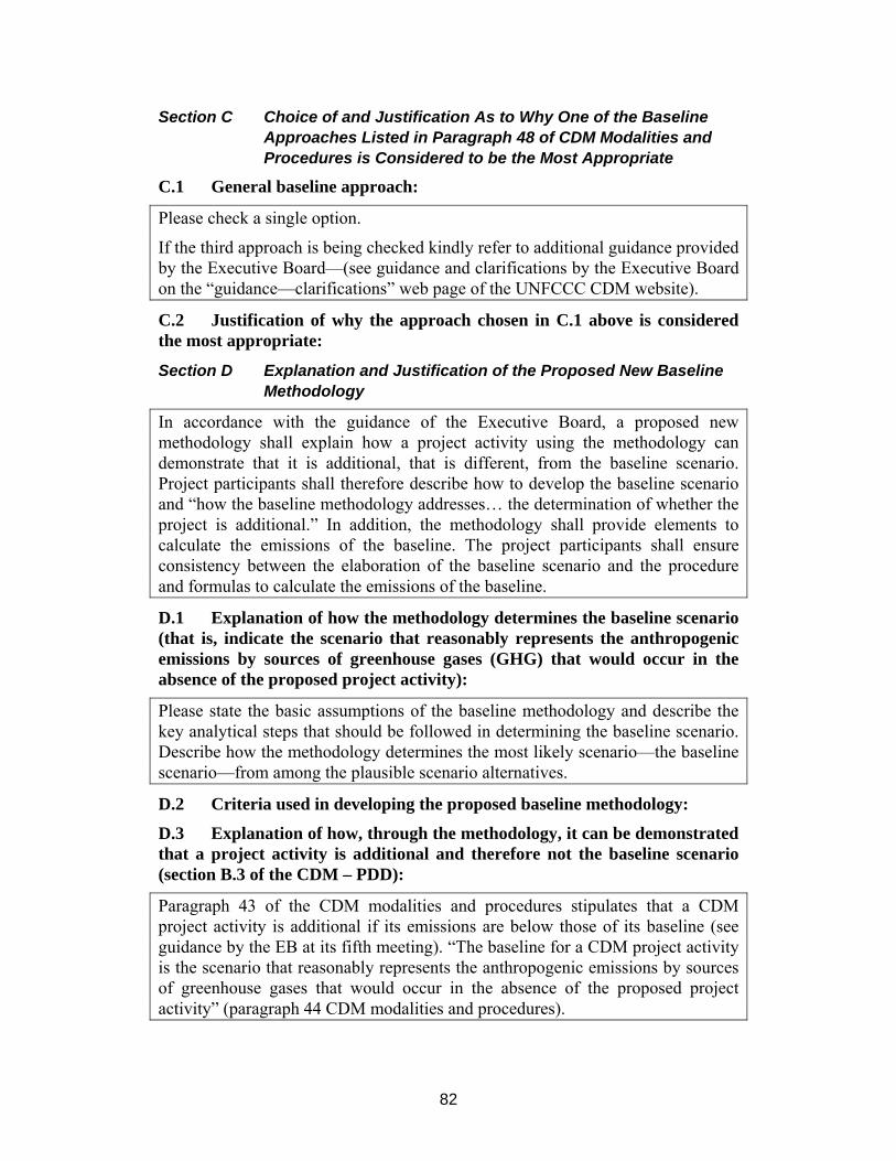
82
Section C Choice of and Justification As to Why One of the Baseline Approaches Listed in Paragraph 48 of CDM Modalities and Procedures is Considered to be the Most Appropriate
C.1 General baseline approach:
Please check a single option.
If the third approach is being checked kindly refer to additional guidance provided by the Executive Board—(see guidance and clarifications by the Executive Board on the “guidance—clarifications” web page of the UNFCCC CDM website).
C.2 Justification of why the approach chosen in C.1 above is considered the most appropriate:
Section D Explanation and Justification of the Proposed New Baseline Methodology
In accordance with the guidance of the Executive Board, a proposed new methodology shall explain how a project activity using the methodology can demonstrate that it is additional, that is different, from the baseline scenario. Project participants shall therefore describe how to develop the baseline scenario and “how the baseline methodology addresses… the determination of whether the project is additional.” In addition, the methodology shall provide elements to calculate the emissions of the baseline. The project participants shall ensure consistency between the elaboration of the baseline scenario and the procedure and formulas to calculate the emissions of the baseline.
D.1 Explanation of how the methodology determines the baseline scenario (that is, indicate the scenario that reasonably represents the anthropogenic emissions by sources of greenhouse gases (GHG) that would occur in the absence of the proposed project activity):
Please state the basic assumptions of the baseline methodology and describe the key analytical steps that should be followed in determining the baseline scenario. Describe how the methodology determines the most likely scenario—the baseline scenario—from among the plausible scenario alternatives.
D.2 Criteria used in developing the proposed baseline methodology:
D.3 Explanation of how, through the methodology, it can be demonstrated that a project activity is additional and therefore not the baseline scenario (section B.3 of the CDM – PDD):
Paragraph 43 of the CDM modalities and procedures stipulates that a CDM project activity is additional if its emissions are below those of its baseline (see guidance by the EB at its fifth meeting). “The baseline for a CDM project activity is the scenario that reasonably represents the anthropogenic emissions by sources of greenhouse gases that would occur in the absence of the proposed project activity” (paragraph 44 CDM modalities and procedures).
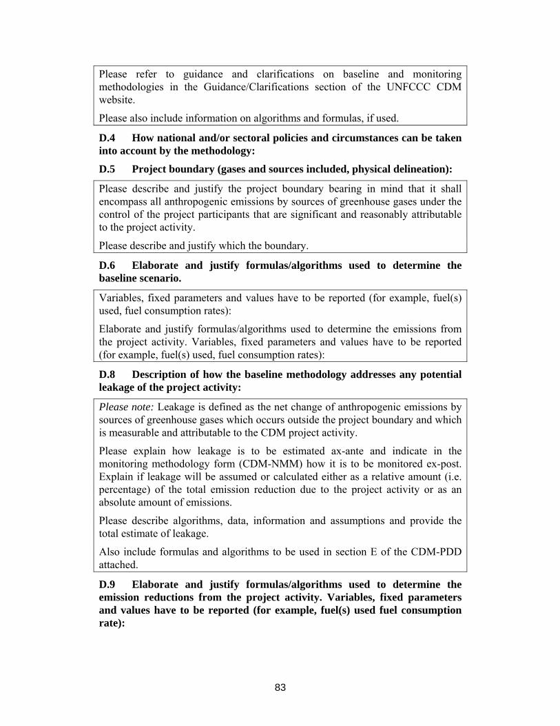
83
Please refer to guidance and clarifications on baseline and monitoring methodologies in the Guidance/Clarifications section of the UNFCCC CDM website.
Please also include information on algorithms and formulas, if used.
D.4 How national and/or sectoral policies and circumstances can be taken into account by the methodology:
D.5 Project boundary (gases and sources included, physical delineation):
Please describe and justify the project boundary bearing in mind that it shall encompass all anthropogenic emissions by sources of greenhouse gases under the control of the project participants that are significant and reasonably attributable to the project activity.
Please describe and justify which the boundary.
D.6 Elaborate and justify formulas/algorithms used to determine the baseline scenario.
Variables, fixed parameters and values have to be reported (for example, fuel(s) used, fuel consumption rates):
Elaborate and justify formulas/algorithms used to determine the emissions from the project activity. Variables, fixed parameters and values have to be reported (for example, fuel(s) used, fuel consumption rates):
D.8 Description of how the baseline methodology addresses any potential leakage of the project activity:
Please note: Leakage is defined as the net change of anthropogenic emissions by sources of greenhouse gases which occurs outside the project boundary and which is measurable and attributable to the CDM project activity.
Please explain how leakage is to be estimated ax-ante and indicate in the monitoring methodology form (CDM-NMM) how it is to be monitored ex-post. Explain if leakage will be assumed or calculated either as a relative amount (i.e. percentage) of the total emission reduction due to the project activity or as an absolute amount of emissions.
Please describe algorithms, data, information and assumptions and provide the total estimate of leakage.
Also include formulas and algorithms to be used in section E of the CDM-PDD attached.
D.9 Elaborate and justify formulas/algorithms used to determine the emission reductions from the project activity. Variables, fixed parameters and values have to be reported (for example, fuel(s) used fuel consumption rate):

84
Section E. Data Sources and Assumptions
E.1 Describe parameters and/or assumptions (including emission factors and activity levels):
E.2 List data used indicating sources (for example, official statistics, expert judgment, proprietary data, IPCC, commercial and scientific literature) and precise references and justify the appropriateness of the choice of such data:
E.3 Vintage of data (for example, relative to starting date of the project activity):
E.4 Spatial level of data (local, regional, national):
Section F. Assessment of Uncertainties (Sensitivity to Key Factors and Assumptions)
Please highlight any factors and assumptions that would have a significant impact on the baseline and/or the calculation of baseline emission levels and how uncertainty related to those assumptions and factors are to be addressed.
Section G. Explanation of How the Baseline Methodology Allows for the Development of Baselines in a Transparent and Conservative Manner
A.7.2 Monitoring (CDM-NMM) Section A: Identification of Methodology:
A.1 Proposed methodology title:
Provide an unambiguous title for a proposed methodology. Avoid project-specific titles. The title, once approved, should allow project participants to get an indication of the applicability of an approved methodology.
A.2 List of category(ies) of project activity to which the methodology may apply:
Use the list of categories of project activities and of registered CDM project activities by category available on the UNFCCC CDM website, please specify the category(ies) of project activities for which this proposed new methodology can be used. If no suitable category(ies) of project activities can be identified, please suggest a new category(ies) descriptor and its definition, being guided by relevant information on the UNFCCC CDM website.
A.3 Conditions under which the methodology is applicable to CDM project activities:
Provide conditions under which the methodology is applicable to CDM project activities: (for example, circumstances, region, data, availability, resource availability). Please indicate if an approved methodology exists for the same conditions of application.

85
A.4 What are the potential strengths and weaknesses of this proposed new methodology?
Please outline how the accuracy and completeness of the new methodology compares to that of approved methodologies, in particular with regard to approved methodologies for the same conditions of application.
Section B. Proposed New Monitoring Methodology
Please provide a detailed description plan, including the identification of data and its quality with regard to accuracy, comparability, completeness and validity.
Different types of project activities will have different monitoring requirements. For some project activities, emission reductions are calculated as the differences between the project activity and the baseline emissions. For others emission reductions are monitored directly.
Depending on the type of project activity, please fill out their option 1 or option 2.
Option 1 (section 2.2): Please describe the data and information that will be collected in order to monitor the emissions in the baseline scenario and the project scenario.
Option 2 (section 2.3): Please describe the data and information that will be collected in order to directly monitor and calculate the emission reductions from the project activity.
B.1 Brief description of the new methodology:
Please outline the main points and give a reference to a detailed description of the monitoring methodology.
B.2 Option 1: Monitoring of the emissions in the project scenario and the baseline scenario:
B.2.1 Data to be collected or used in order to monitor emissions from the project activity, and how this data will be archived:
Monitored data shall be archived for 2 years following the end of the crediting period.
Header of table and titles of columns shall not be modified and columns shall not be deleted.
Please add rows to the table below, as needed.
B.2.2 Description of formulas used to estimate project emissions (for each gas, source, formulas/algorithm, emissions units of CO2e):
Formulas should be consistent with the formulas outlined in the description of the baseline methodology.
B.2.3 Relevant data necessary for determining the baseline of anthropogenic emissions by source of greenhouses gases (GHG) within the project boundary and how such data will be collected and archived:

86
Monitored data shall be archived for 2 years following the end of the crediting period.
Header of table and titles of columns shall not be modified and columns shall not be deleted.
Please add rows to the table below, as needed.
B.2.4 Description of formulas used to estimate baseline emissions (for each gas, source, formulas/algorithm, emissions units of CO2e):
Formulas should be consistent with the formulas outlined in the description of the baseline methodology.
B.3 Option 2: Direct Monitoring of Emission Reductions from the Project Activity
Value should be consistent with those in section E of the CDM-PDD.
B.3.1 Data to be collected or used in order to monitor emissions from the project activity, and how data will be archived.
Monitored data shall be archived for 2 years following the end of the crediting period.
Header of table and titles of columns shall not be modified and columns shall not be deleted.
Please add rows to the table below, as needed.
B.3.2 Description of formulas used to calculate project emissions (for each gas, source, formulas/algorithm, emissions units of CO2e):
Formulas should be consistent with the formulas outlined in the description of the baseline methodology.
B.4 Treatment of leakage in the monitoring plan:
Please explain if leakage will be monitored during the implementation of the project activity. If relevant, please explain and justify if leakage will not be estimated ex-post. Explain if leakage will be calculated as the difference between emissions occurring outside the boundaries of the project and emissions in the baseline scenario, or if leakage will be monitored directly.
B.4.1 If applicable, please describe the data and information that will be collected in order to monitor leakage effects of the project activity:
Monitored data shall be archived for 2 years following the end of the crediting period.
Header of table and titles of columns shall not be modified and columns shall not be deleted.
Please add rows to the table below, as needed.

87
B.4.2 Description of formulas used to estimate leakage (for each gas, source, formulas/algorithm, emissions units of CO2e):
Formulas should be consistent with the formulas outlined in the description of the baseline methodology.
B.5 Description of formulas used to estimate emission reductions for the project activity (for each gas, source, formulas/algorithm, emissions units of CO2e):
Formulas should be consistent with the formulas outlined in the description of the baseline methodology.
B.6 Assumptions used in elaborating the new methodology:
Please list information used in the calculation of emissions which is not measured or calculated, for example, use of any default emission factors.
B.7 Please indicate whether quality control (QC) and quality assurance (QA) procedures are being undertaken for the items monitored:
See tables in sections B.2 or B.3 and B.4 above.
Header of table and titles of columns shall not be modified and columns shall not be deleted.
Rows are allowed to be added, as needed.
B.8 Has the methodology been applied successfully elsewhere and, if so, in which circumstances?
