gas-liquid two phase flow through a vertical 90deg elbow bend
TRANSCRIPT

Gas-liquid two phase flow through a vertical 90deg elbow bend
Spedding, P. L., & Benard, E. (2007). Gas-liquid two phase flow through a vertical 90deg elbow bend.Experimental Thermal and Fluid Science, 31 (7)(7), 761-769.https://doi.org/10.1016/j.expthermflusci.2006.08.003
Published in:Experimental Thermal and Fluid Science
Queen's University Belfast - Research Portal:Link to publication record in Queen's University Belfast Research Portal
General rightsCopyright for the publications made accessible via the Queen's University Belfast Research Portal is retained by the author(s) and / or othercopyright owners and it is a condition of accessing these publications that users recognise and abide by the legal requirements associatedwith these rights.
Take down policyThe Research Portal is Queen's institutional repository that provides access to Queen's research output. Every effort has been made toensure that content in the Research Portal does not infringe any person's rights, or applicable UK laws. If you discover content in theResearch Portal that you believe breaches copyright or violates any law, please contact [email protected].
Download date:04. Apr. 2022

1
2
3
4
56
7
89
10111213141516171819
2021
22
2324252627282930313233
ETF 6851 No. of Pages 9, Model 5+
28 August 2006 Disk UsedARTICLE IN PRESS
www.elsevier.com/locate/etfs
Experimental Thermal and Fluid Science xxx (2006) xxx–xxx
OF
Gas–liquid two phase flow through a vertical 90� elbow bend
P.L. Spedding, E. Benard *
School of Aeronautical Engineering, Queen’s University Belfast, BT9 5AH, UK
Received 24 March 2006; received in revised form 1 August 2006; accepted 7 August 2006
CTED
PR
O
Abstract
Pressure drop data are reported for two phase air–water flow through a vertical to horizontal 90� elbow bend set in 0.026 m i.d. pipe.The pressure drop in the vertical inlet tangent showed some significant differences to that found for straight vertical pipe. This was causedby the elbow bend partially choking the inflow resulting in a build-up of pressure and liquid in the vertical inlet riser and differences in thestructure of the flow regimes when compared to the straight vertical pipe. The horizontal outlet tangent by contrast gave data in generalagreement with literature even to exhibiting a drag reduction region at low liquid rates and gas velocities between 1 and 2 m s�1.
The elbow bend pressure drop was best correlated in terms of le/d determined using the actual pressure loss in the inlet vertical riser.The data showed a general increase with fluid rates that tapered off at high fluid rates and exhibited a negative pressure region at lowrates. The latter was attributed to the flow being smoothly accommodated by the bend when it passed from slug flow in the riser tosmooth stratified flow in the outlet tangent.
A general correlation was presented for the elbow bend pressure drop in terms of total Reynolds numbers. A modified Lockhart–Martinelli model gave prediction of the data.� 2006 Elsevier Inc. All rights reserved.
Keywords: Air–water flow; Two phase flow in bend; Bend pressure loss; Prediction of pressure loss
E
34353637383940414243444546
UNC
OR
R1. Introduction
Single phase pressure drop can be predicted for curvedpipes [1]. Recently Crawford et al. [2] extended the predic-tion ability to tight bends. Early work on two phase flow incurved pipes and bends highlighted difficulties in under-standing the pressure drop characteristics [3–6]. Detailedstudies of two phase pressure loss have largely beenconfined to the horizontal plane. Chenoweth and Martin[7] showed that while two phase pressure drop aroundbends was higher than for single phase flow it could becorrelated by an adoption of the Lockhart–Martinelli [8]model developed originally for straight pipe. The correla-
474849505152
0894-1777/$ - see front matter � 2006 Elsevier Inc. All rights reserved.
doi:10.1016/j.expthermflusci.2006.08.003
* Corresponding author. Tel.: +44 28 9097 4180; fax: +44 28 9097 5576.E-mail address: [email protected] (E. Benard).
Please cite this article as: P.L. Spedding, E. Benard, Gas–liquid two pmal and Fluid Science (2006), doi:10.1016/j.expthermflusci.2006.08.
tion was claimed to predict loss in bends and other pipe fit-tings. Also at high mass velocities agreement was achievedwith the homogeneous model. Fitzsimmons [9] presentedtwo phase bend pressure loss data in terms of the equiva-lent length, le/d (i.e. the bend pressure loss over straightpipe frictional pressure gradient) and the Lockhart–Marti-nelli multiplier /2
GB referred to the single phase gas pressureloss in the bend. Comparison against pressure drop instraight pipe gave a poor correlation. Sekoda et al. [10] alsoused /2
LB referred to single phase liquid pressure loss in thebend. The two phase bend pressure drop was found to beindependent of pipe diameter and depended on R/d in amanner similar to that found for single phase flow. Bruce[11] confirmed that the standard Lockhart–Martinelliparameter over-predicted bend pressure loss. Also thehomogeneous model gave acceptable prediction of R12
refrigerant for bends presumably at high mass flows. Free-ston and Dole [12,13] presented widely scattered geother-mal data. For long and short radius bends results were
hase flow through a vertical 90� elbow bend, Experimental Ther-003
T
RO
OF
53545556575859606162636465666768697071727374757677787980818283848586878889
90919293949596979899100101102103104
105
106107108109110111112113114115116117118119120121122123124
Nomenclature
d pipe internal diameter, mG mass flow rate, kg m�2 s�1
L pipe length, m‘e equivalent length, mP pressure, kg m�1 s�2
Q volume flow rate, m3 s�1
R centre line radius of bend, mRe Reynolds number, dV q=lU* shear velocity, m s�1
V velocity, m s�1
W mass flow rate, kg s�1
X Lockhart–Martinelli parameter, Eq. (4)X,Y,Z inlet pipe, bend, outlet pipe, length, m.q density, kg m�3
l viscosity, kg m�1 s�1
/ Lockhart–Martinelli pressure parameter
Subscripts
A total mass as liquidB bendE equivalentf frictionG gasL liquidP phaseS superficialT totalX fluid
2 P.L. Spedding, E. Benard / Experimental Thermal and Fluid Science xxx (2006) xxx–xxx
ETF 6851 No. of Pages 9, Model 5+
28 August 2006 Disk UsedARTICLE IN PRESS
UN
CO
RR
EC
R/d = 90, le/d = 225 [±20%]; R/d = 1.5, le/d = 58 [+30% to�40%]; Tee, le/d = 115 [+50% to �75%]. Despite wide var-iation of the data it was used by the Engineering ScienceData Unit [14] to develop a model for two phase flowthrough pipe components. Chisholm [15] presented an ele-mentary model for prediction of two phase flow in bends,based on /2
LA, which was claimed to give prediction forall pipe diameters, R/d values and flow rates. Noersteboe[16] showed the model gave high values of bend pressureloss when checked against refrigerant data. Most studieshave taken little interest in the actual flow regimes present.In some cases they are mentioned only in passing. How-ever, Hoang and Davies [17] have realised the significanceof flow regimes and have reported data on bubbly flow invertical return bends. Graf and Neti [18] studied two phasepressure drop in square bends. Reported work on the ori-entation of the plane of the bend has often given contraryresults. Deobold [19] claimed that the horizontal bend, thehorizontal to vertical up bend and the vertical down to hor-izontal bend all gave the same bend pressure loss. Howevera horizontal to vertical down bend had a pressure drop thatwas 35% less. The correlation for elevation was assumed tofollow the homogeneous model by Deobold [19] but otherssuch as Alves [20] ignored head pressure differencesentirely. Peshkin [21] reported that horizontal to verticaldown flow had about 10% more bend pressure drop thanthe corresponding horizontal to vertical up flow case.Kutateladze [22] by contrast concluded the direct oppositethat the horizontal to vertical up flow bend created thegreater pressure drop. Pressure drop in geothermal expan-sion loops also reported some contrary results [23–25].Studies in helical coils and boilers have been conducted[26–33]. Modelling of the pressure drop data have beenattempted with the Lockhart–Martinelli parameter [8] orthe Baroczy [34] model [32,33]. Hart et al. [30] also devel-oped models for low liquid flows. Rippel et al. [31] showedthat the bend pressure loss varied significantly with the flow
Please cite this article as: P.L. Spedding, E. Benard, Gas–liquid two pmal and Fluid Science (2006), doi:10.1016/j.expthermflusci.2006.08.
ED
Pregime present. Work has recently been presented on waterhammer in bends [35].
It can be concluded that a two phase flow through acurved pipe and elbow bends possesses similar features tothose for a single phase flow. It is not clear as to the bestmethod of data presentation and modelling, while theeffects of flow regimes on the pressure drop which mustbe of significance requires elucidation. Currently uncertain-ties have been handled by over design. Such an approach issuspect particularly where safety issues are involved. Forexample, conveying to a destructor unit of the suddenrelease from safety valves where unexpected back pressurecould be a real hazard.
In this work two phase air water flow through a vertical90� to horizontal elbow bend is investigated.
2. Experimental
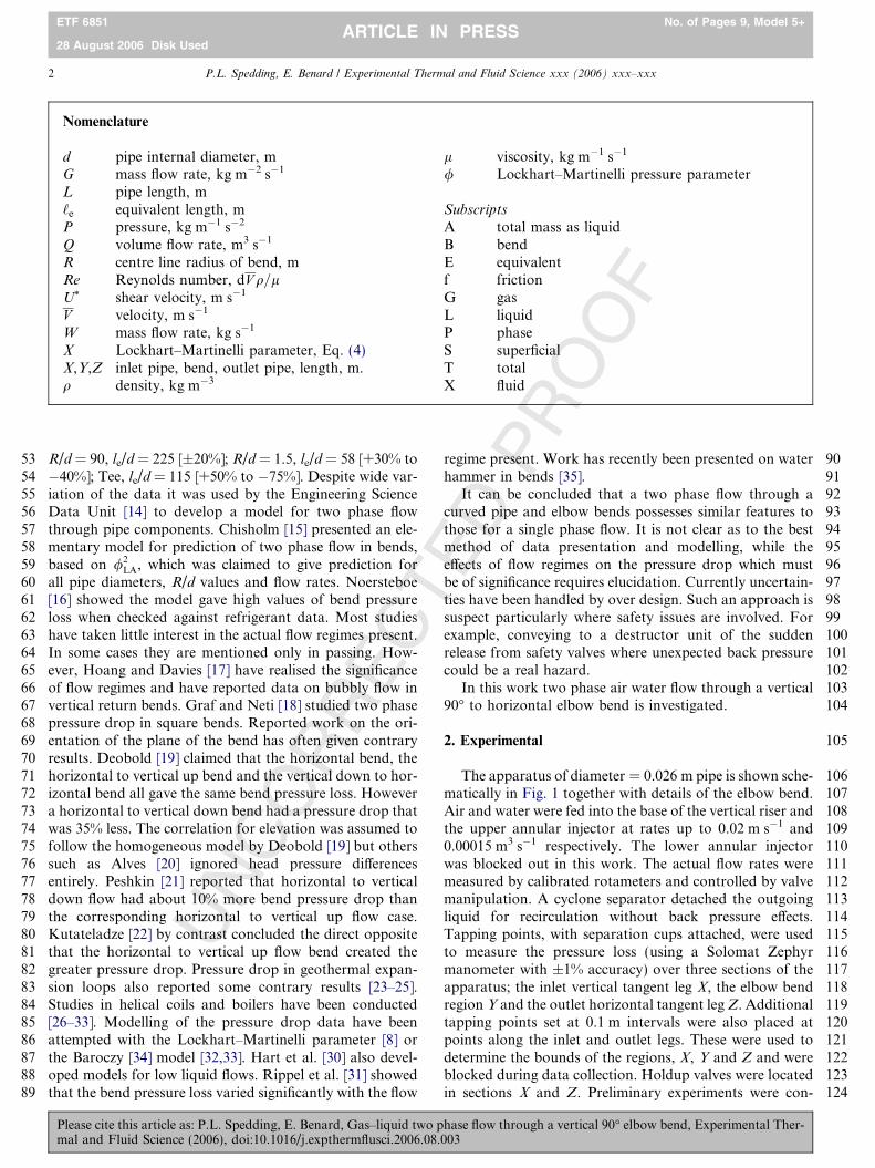
The apparatus of diameter = 0.026 m pipe is shown sche-matically in Fig. 1 together with details of the elbow bend.Air and water were fed into the base of the vertical riser andthe upper annular injector at rates up to 0.02 m s�1 and0.00015 m3 s�1 respectively. The lower annular injectorwas blocked out in this work. The actual flow rates weremeasured by calibrated rotameters and controlled by valvemanipulation. A cyclone separator detached the outgoingliquid for recirculation without back pressure effects.Tapping points, with separation cups attached, were usedto measure the pressure loss (using a Solomat Zephyrmanometer with ±1% accuracy) over three sections of theapparatus; the inlet vertical tangent leg X, the elbow bendregion Y and the outlet horizontal tangent leg Z. Additionaltapping points set at 0.1 m intervals were also placed atpoints along the inlet and outlet legs. These were used todetermine the bounds of the regions, X, Y and Z and wereblocked during data collection. Holdup valves were locatedin sections X and Z. Preliminary experiments were con-
hase flow through a vertical 90� elbow bend, Experimental Ther-003
CO
RR
EC
T
PR
OO
F
125126127128129130131132133134135136
137
138139140141142143144145146147148149150151152153154155156157158159160161162163164165166167
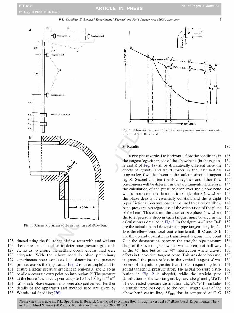
Fig. 2. Schematic diagram of the two-phase pressure loss in a horizontalto vertical 90� elbow bend.
Fig. 1. Schematic diagram of the test section and elbow bend.
P.L. Spedding, E. Benard / Experimental Thermal and Fluid Science xxx (2006) xxx–xxx 3
ETF 6851 No. of Pages 9, Model 5+
28 August 2006 Disk UsedARTICLE IN PRESS
UNducted using the full range of flow rates with and without
the elbow bend in place to determine pressure gradientsetc so as to ensure the settling down lengths used wereadequate. With the elbow bend in place preliminaryexperiments were conducted to determine the pressureprofiles across the apparatus (Fig. 2 is an example) and toensure a linear pressure gradient in regions X and Z so asto allow accurate extrapolation into region Y. The pressureat the base of the inlet leg varied up to 1.35 · 105 kg m�1 s�2
(a). Single phase experiments were also performed. Furtherdetails of the apparatus and method used are given byWoods and Spedding [36].
Please cite this article as: P.L. Spedding, E. Benard, Gas–liquid two pmal and Fluid Science (2006), doi:10.1016/j.expthermflusci.2006.08.
ED
3. Results
In two phase vertical to horizontal flow the conditions inthe tangent legs either side of the elbow bend (in the regionsX and Z of Fig. 1) will be dramatically different since theeffects of gravity and uplift forces in the inlet verticaltangent leg X will be absent in the outlet horizontal tangentleg Z. Secondly, often the flow regimes and other flowphenomena will be different in the two tangents. Therefore,the calculation of the pressure drop over the elbow bendwill be more complex than that for single phase flow wherethe phase density is essentially constant and the straightpipes frictional pressure loss can be used to calculate elbowbend pressure loss regardless of the orientation of the planeof the bend. This was not the case for two phase flow wherethe total pressure drop in each tangent must be used in thecalculation as detailed in Fig. 2. In the figure A–C and D–Fare the actual up and downstream pipe tangent lengths, C–D is the elbow bend total centre line length, B–C and D–Eare the up and downstream transitional regions. The pointG is the demarcation between the straight pipe pressuredrop of the two tangents which was chosen, not half wayat the 45� line but at the 90� intersection where gravityeffects in the vertical tangent cease. This was done because,in general the pressure loss in the vertical tangent X wasorders of magnitude greater than the corresponding hori-zontal tangent Z pressure drop. The actual pressure distri-bution in Fig. 2 is abcgdef, while the straight pipedistribution in the two tangent legs are abc 0g 0 and g 0d 0e 0f 0.The corrected pressure distribution abc 0g00d000e000f000 includesa straight pipe loss equal to the actual length C–D of theelbow bend centre line, DPBE, that is composed of C–G
hase flow through a vertical 90� elbow bend, Experimental Ther-003

TED
PR
OO
F168169170171172173174175176177178179180181182183184185186187188189190191192
193194195196197198199200201202203204205206207208209210211212213214215216217
Table 1Two phase flow in curved pipe and bends
Fluids Diameter(m)
Rd
Geometry Flow Correlation Ref.
Air–water 0.0780 7.5 180� bend Horizontal /2LA against QL/QT [7]
Steam–water 0.0488 1, 1.5, 5.2 90� bend Horizontal /2GB against le/d [9]
Air–water 0.018, 0.0257 2.36, 5.02 90� bend Horizontal /2LB [10]
Air–water 0.019 4.6, 10.5, 90� bend Horizontal /2LB [11]
R12 14.5, 22.6Air–water 0.019 1, 2, 3, 4, 5, 6 90� bend Horizontal /2
LB [11]Steam–water 0.01 0.75, 4.5 90�, 45�, 180� bends Horizontal le/d against V L [12]R12, R717 0.0223,
0.0825, 0.1201.3, 1.4 90�, 180� bends Horizontal DPTP � DPLA/DPGA � DPLA [16]
Air–water 0.0266 7 180� bend Horizontal tovertical
le/d against ReSG [20]
Air–oilSteam–water 0.0266 1.5 90� bends in vertical
square coilHorizontal, upand down vertical
/2L [19]
Steam–water 0.307 1.5 90� bends inexpansion loop
Horizontal to updown vertical
/2L [23]
Steam–water 0.201 1.5 90� bends Up, down verticalto horizontal
/2L against WG/WL [24]
Air–water 0.0102 9.95 Up right helical Down /2G [31]
He–waterFreon 12–waterAir–2/propanolAir–water 0.0159 4.8, 7.2, 9.6 Up right helical Up Film inversion [27]Steam–water 0.0127 22.8, 52.0,
92.9, 101.6Up right helical Up /2
LA [32]
Air–water 0.0147 14.4 Up right helical Up RL [33]Air–aq glycerolAir–water 0.0254 1, 5, 10 30�, 45�, 60�, 90�
vertical to horizontalUp Data [28]
Air–water 0.0254 12 180� vertical Up/down Data [29]
4 P.L. Spedding, E. Benard / Experimental Thermal and Fluid Science xxx (2006) xxx–xxx
ETF 6851 No. of Pages 9, Model 5+
28 August 2006 Disk UsedARTICLE IN PRESS
UN
CO
RR
EC
and G–D the two elements from each tangent leg. Thus thetotal bend pressure drop DPBT is composed of the bendpressure loss from the inlet and outlet tangent legs pressuregradients DPB and the equivalent centre line bend lengthDPBE (see Table 1).
In the calculation of DPBT it was assumed that theactual pressure drops in the vertical X and horizontal Ztangents should be used to determine DPBE. While thelatter should not cause any problems the former pressuredrop may be different to that in a straight vertical pipewithout the following elbow. Spedding et al. [37] showedthat for near vertical two phase flow slight disturbancesin the distribution of the fluids across the pipe generallyled to a rise in pressure drop over that observed for thecorresponding straight vertical pipe [38] due, in the main,to increased liquid holdup. Therefore, possible distur-bances due to the elbow bend could affect the flow in thevertical tangent X by instituting some measure of chokingand increased pressure loss.
Firstly, the actual straight pipe tangent pressure loss insections X and Z of Fig. 1 were compared with reportedtwo phase data for vertical and horizontal flow respec-tively. This was done to determine if the elbow bend didindeed have any effect on the flow in the tangent legs. Figs.3–6 detail the results for four different liquid rates. As the
Please cite this article as: P.L. Spedding, E. Benard, Gas–liquid two pmal and Fluid Science (2006), doi:10.1016/j.expthermflusci.2006.08.
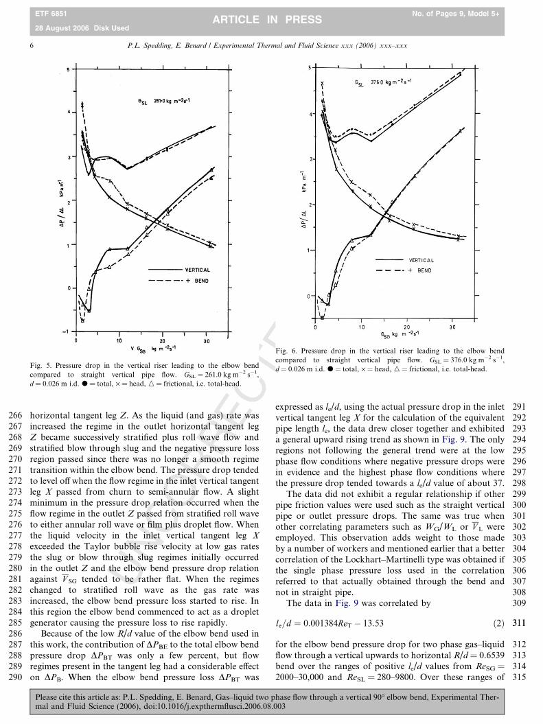
gas rate was increased for a set liquid rate the flow patternspassed successively from slug to churn to semi-annular andthen annular flow. At the lowest liquid rate in Fig. 3 thetotal pressure drop with the elbow bend was above thatfor undisturbed straight vertical pipe flow in the slug andsome churn flows at low gas rates GSG < 4.2 kg m�2 s�1.Thereafter, at higher gas rates the total pressure drops werethe same for both systems. At low gas rates aboutGSG = 0.8–1.5 kg m�2 s�1 the frictional pressure drop(being the total minus the head) gave a negative value.As the liquid rate was increased from Figs. 3–6 a differencebetween the total pressure loss between the two systemsbegan to appear which eventually extended progressivelyacross the entire gas range. In the regions where the pres-sure loss was larger with the inclusion of the elbow bend,the flow regimes between the two systems exhibited subtledifferences, e.g. the slugs tended to be of shorter length withthe elbow bend resulting in a narrower but increased fre-quency of pressure fluctuations. In addition, the liquidholdup tended to be higher with the elbow bend which,particularly at the higher liquid rates, led to the head pres-sure loss with the elbow bend being above that of thestraight vertical pipe. Indeed the head pressure loss exhib-ited a more marked effect with increasing gas rate than thetotal head loss. The effect of uplift was less noticeable with
hase flow through a vertical 90� elbow bend, Experimental Ther-003

TED
PR
OO
F218219220221222223224225226227228229230231232233234235236237
239239
240241
242
243
244245246247248249250251252253254255256257258259260261262263264265
Fig. 3. Pressure drop in the vertical riser leading to the elbow bendcompared to straight vertical pipe flow. GSL = 10.97 kg m�2 s�1,d = 0.026 m i.d. Frictional pressure drop, total pressure loss minus headpressure drop calculated from holdup.
Fig. 4. Pressure drop in the vertical riser leading to the elbow bendcompared to straight vertical pipe flow. GSL = 62.67 kg m�2 s�1,d = 0.026 m i.d. Frictional pressure drop, total pressure loss minus headpressure drop calculated from holdup.
P.L. Spedding, E. Benard / Experimental Thermal and Fluid Science xxx (2006) xxx–xxx 5
ETF 6851 No. of Pages 9, Model 5+
28 August 2006 Disk UsedARTICLE IN PRESS
UN
CO
RR
ECthe elbow bend in place and the frictional loss was virtually
unaltered from that of the straight vertical pipe. Thus theinclusion of the elbow bend gave a similar effect to thatnoted by Spedding et al. [37], for the case when the pipewas slightly off the vertical where the anisotropy of theliquid flow caused an increase in both liquid holdup andpressure drop over vertical pipe under similar conditions.In addition the elbow bend caused an increase in the abso-lute pressure within the inlet vertical tangent leg X due to ameasure of throttling of the flow by the elbow bend. Thusthe presence of the elbow bend often led to an increase inpressure drop in the inlet vertical tangent leg X thatresulted in an increase in DPBE. Figs. 3–6 therefore are ofvalue as they provide some estimate of the excess pressureexpected in the inlet vertical tangent leading to an elbowbend.
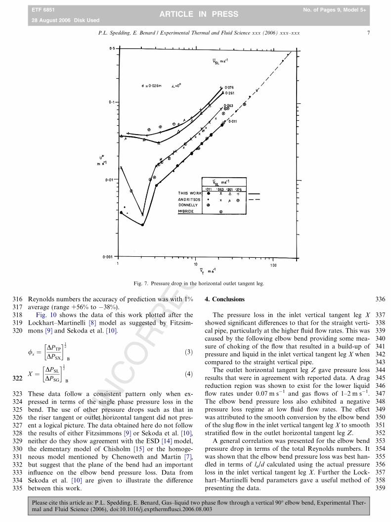
The outlet horizontal tangent leg Z exhibited a pressuredrop that showed agreement with other reported horizon-tal data [39–41] as shown in Fig. 7. The data were presentedin terms of shear velocity
U � ¼
ffiffiffiffiffiffiffiffiffiffiffiffiffiffiDPDL
� �sf
d4qL
ð1Þ
following the method of Spedding et al. [42]. One interest-ing feature in Fig. 7 was that at low liquid velocities and
Please cite this article as: P.L. Spedding, E. Benard, Gas–liquid two pmal and Fluid Science (2006), doi:10.1016/j.expthermflusci.2006.08.
gas rates V SG = 1.5–2.5 m s�1 there was a region of drag
reduction where DP TP
DP SG
h i0:5
¼ /G < 1:0. This was in agree-
ment with the findings of Ferguson and Spedding [43]who reported on this phenomenon in two phase horizontalflow in pipes with a size range of 0.045–0.051 m i.d. Thiswork shows that the effect appeared at the lower diameterof 0.026 m as well. Fig. 8 gives the total elbow bend pres-sure drop DPBT for four liquid rates. At the lower liquidrates, the elbow bend positive pressure drop passedthrough a slight minimum value as V SG was increased.As the liquid rate increased the pressure drop rose steadilywith V SG and possessed very few other features. There wasan observable difference between the pressure drop relationthat depended on whether V SL was below or above the freebubble rise velocity in the inlet vertical tangent leg X. Atthe lower liquid (and gas rates) the elbow bend pressuredrop was negative while at the highest liquid (and gas rate)the pressure drop commenced to level off.
These observed effects can be attributed to the flowregimes present in the two tangent legs of the elbow bend.The negative elbow bend pressure drop region at the lowerphase flow rates occurred when the slug regime in the inletvertical tangent leg X passed smoothly through the elbowbend and formed the smooth stratified regime in the outlet
hase flow through a vertical 90� elbow bend, Experimental Ther-003
TED
PR
OO
F266267268269270271272273274275276277278279280281282283284285286287288289290
291292293294295296297298299300301302303304305306307308309
311311
312313314315
Fig. 5. Pressure drop in the vertical riser leading to the elbow bendcompared to straight vertical pipe flow. GSL = 261.0 kg m�2 s�1,d = 0.026 m i.d. d = total, · = head, n = frictional, i.e. total-head.
Fig. 6. Pressure drop in the vertical riser leading to the elbow bendcompared to straight vertical pipe flow. GSL = 376.0 kg m�2 s�1,d = 0.026 m i.d. d = total, · = head, n = frictional, i.e. total-head.
6 P.L. Spedding, E. Benard / Experimental Thermal and Fluid Science xxx (2006) xxx–xxx
ETF 6851 No. of Pages 9, Model 5+
28 August 2006 Disk UsedARTICLE IN PRESS
UN
CO
RR
EC
horizontal tangent leg Z. As the liquid (and gas) rate wasincreased the regime in the outlet horizontal tangent legZ became successively stratified plus roll wave flow andstratified blow through slug and the negative pressure lossregion passed since there was no longer a smooth regimetransition within the elbow bend. The pressure drop tendedto level off when the flow regime in the inlet vertical tangentleg X passed from churn to semi-annular flow. A slightminimum in the pressure drop relation occurred when theflow regime in the outlet Z passed from stratified roll waveto either annular roll wave or film plus droplet flow. Whenthe liquid velocity in the inlet vertical tangent leg X
exceeded the Taylor bubble rise velocity at low gas ratesthe slug or blow through slug regimes initially occurredin the outlet Z and the elbow bend pressure drop relationagainst V SG tended to be rather flat. When the regimeschanged to stratified roll wave as the gas rate wasincreased, the elbow bend pressure loss started to rise. Inthis region the elbow bend commenced to act as a dropletgenerator causing the pressure loss to rise rapidly.
Because of the low R/d value of the elbow bend used inthis work, the contribution of DPBE to the total elbow bendpressure drop DPBT was only a few percent, but flowregimes present in the tangent leg had a considerable effecton DPB. When the elbow bend pressure loss DPBT was
Please cite this article as: P.L. Spedding, E. Benard, Gas–liquid two pmal and Fluid Science (2006), doi:10.1016/j.expthermflusci.2006.08.
expressed as le/d, using the actual pressure drop in the inletvertical tangent leg X for the calculation of the equivalentpipe length le, the data drew closer together and exhibiteda general upward rising trend as shown in Fig. 9. The onlyregions not following the general trend were at the lowphase flow conditions where negative pressure drops werein evidence and the highest phase flow conditions wherethe pressure drop tended towards a le/d value of about 37.
The data did not exhibit a regular relationship if otherpipe friction values were used such as the straight verticalpipe or outlet pressure drops. The same was true whenother correlating parameters such as WG/WL or V L wereemployed. This observation adds weight to those madeby a number of workers and mentioned earlier that a bettercorrelation of the Lockhart–Martinelli type was obtained ifthe single phase pressure loss used in the correlationreferred to that actually obtained through the bend andnot in straight pipe.
The data in Fig. 9 was correlated by
le=d ¼ 0:001384ReT � 13:53 ð2Þ
for the elbow bend pressure drop for two phase gas–liquidflow through a vertical upwards to horizontal R/d = 0.6539bend over the ranges of positive le/d values from ReSG =2000–30,000 and ReSL = 280–9800. Over these ranges of
hase flow through a vertical 90� elbow bend, Experimental Ther-003
TED
PR
OO
F316317318319320
322322
323324325326327328329330331332333334335
336
337338339340341342343344345346347348349350351352353354355356357358359
Fig. 7. Pressure drop in the horizontal outlet tangent leg.
P.L. Spedding, E. Benard / Experimental Thermal and Fluid Science xxx (2006) xxx–xxx 7
ETF 6851 No. of Pages 9, Model 5+
28 August 2006 Disk UsedARTICLE IN PRESS
UN
CO
RR
EC
Reynolds numbers the accuracy of prediction was with 1%average (range +56% to �38%).
Fig. 10 shows the data of this work plotted after theLockhart–Martinelli [8] model as suggested by Fitzsim-mons [9] and Sekoda et al. [10].
/x ¼DP TP
DP SX
� �12
B
ð3Þ
X ¼ DP SL
DP SG
� �12
B
ð4Þ
These data follow a consistent pattern only when ex-pressed in terms of the single phase pressure loss in thebend. The use of other pressure drops such as that inthe riser tangent or outlet horizontal tangent did not pres-ent a logical picture. The data obtained here do not followthe results of either Fitzsimmons [9] or Sekoda et al. [10],neither do they show agreement with the ESD [14] model,the elementary model of Chisholm [15] or the homoge-neous model mentioned by Chenoweth and Martin [7],but suggest that the plane of the bend had an importantinfluence on the elbow bend pressure loss. Data fromSekoda et al. [10] are given to illustrate the differencebetween this work.
Please cite this article as: P.L. Spedding, E. Benard, Gas–liquid two pmal and Fluid Science (2006), doi:10.1016/j.expthermflusci.2006.08.
4. Conclusions
The pressure loss in the inlet vertical tangent leg X
showed significant differences to that for the straight verti-cal pipe, particularly at the higher fluid flow rates. This wascaused by the following elbow bend providing some mea-sure of choking of the flow that resulted in a build-up ofpressure and liquid in the inlet vertical tangent leg X whencompared to the straight vertical pipe.
The outlet horizontal tangent leg Z gave pressure lossresults that were in agreement with reported data. A dragreduction region was shown to exist for the lower liquidflow rates under 0.07 m s�1 and gas flows of 1–2 m s�1.The elbow bend pressure loss also exhibited a negativepressure loss regime at low fluid flow rates. The effectwas attributed to the smooth conversion by the elbow bendof the slug flow in the inlet vertical tangent leg X to smoothstratified flow in the outlet horizontal tangent leg Z.
A general correlation was presented for the elbow bendpressure drop in terms of the total Reynolds numbers. Itwas shown that the elbow bend pressure loss was best han-dled in terms of le/d calculated using the actual pressureloss in the inlet vertical tangent leg X. Further the Lock-hart–Martinelli bend parameters gave a useful method ofpresenting the data.
hase flow through a vertical 90� elbow bend, Experimental Ther-003

UN
CO
RR
EC
TED
PR
OO
FFig. 8. Total elbow bend pressure drop against V SG for various liquidrates.
Fig. 9. Elbow bend pressure drop as le/d against ReSG.
Fig. 10. Elbow bend pressure drop according to the Lockhart–Martinelli model. d = 0.018 – R/d = 2.36, 5.02 [10].
8 P.L. Spedding, E. Benard / Experimental Thermal and Fluid Science xxx (2006) xxx–xxx
ETF 6851 No. of Pages 9, Model 5+
28 August 2006 Disk UsedARTICLE IN PRESS
Please cite this article as: P.L. Spedding, E. Benard, Gas–liquid two phase flow through a vertical 90� elbow bend, Experimental Ther-mal and Fluid Science (2006), doi:10.1016/j.expthermflusci.2006.08.003

T
360
361362363364365366367368369370371372373374375376377378379380381382383384385386387388389390391392393394395396397398399400401402403404405406407408409410411412413414
415416417418419420421422423424425426427428429430431432433434435436437438439440441442443444445446447448449450451452453454455456457458459460461462463464465466467
P.L. Spedding, E. Benard / Experimental Thermal and Fluid Science xxx (2006) xxx–xxx 9
ETF 6851 No. of Pages 9, Model 5+
28 August 2006 Disk UsedARTICLE IN PRESS
NC
OR
REC
References
[1] P.L. Spedding, E. Benard, G.M. McNally, Fluid flow through 90degree bends, Dev. Chem. Eng. Min. Process 12 (2004) 107–128.
[2] N.M. Crawford, G. Cunningham, P.L. Spedding, Prediction ofpressure drop for turbulent fluid flow in 90� bends, Proc. Inst. Mech.Eng. 217E (2003) 1–3.
[3] W. Struiver, Two phase fluid flow. Flow through bends andpreliminary study of bends and preliminary study of pressure dropalong pipe, Dominion Physical Lab, New Zealand, ANL 6734-1694R257, 1955.
[4] M.I. Cohen, An investigation of pressure drop in a two-phasetwo-component flow in bends, M.Sc. Thesis, MIT, 1957.
[5] J.R. Castillo, Study of two-phase flow in pipe bends, M.Sc. ThesisMIT, 1957.
[6] L.G. Straub, E. Silberman, Air–water mixture flow through orificesbends and other fittings in a horizontal pipe, St Anthony Falls,Hydraulic Lab., Univ. Minnesota, Rept. 63, 1960.
[7] J.M. Chenoweth, M.W. Martin, Turbulent two-phase flow, Pet. Ref.34 (10) (1955) 151–155.
[8] R.W. Lockhart, R.C. Martinelli, Proposed correlation of data forisothermal two-phase two-component flow in pipes, Chem. Eng.Prog. 45 (1) (1949) 39–48.
[9] P.E. Fitzsimmons, Two phase pressure drop in pipe components.General Electric Res., Rept HW-80970 Rev 1, 1964.
[10] K. Sekoda, Y. Sato, S. Kariya, Horizontal two-phase air–water flowcharacteristics in the disturbed region due to a 90-degree bend, J. Jpn.Soc. Mech. Eng. 35 (289) (1969) 2227–2333.
[11] J.M. Bruce, Two-phase flow in straight pipe and 90� bends, Ph.D.Thesis, Univ. Aberdeen, 1971.
[12] D.H. Freeston, H. Dole, Duct losses in a two-phase steam water flow,in: Aust. Hydo. Fluid Mech. Conf., vol. 6, 1977, pp. 210–215.
[13] D.H. Freeston, Duct losses in a geothermal steam water flow, Univ.Auckland, Dept. Mech. Eng., Rept. 78/5, 1978.
[14] Engineering Science Data Unit Ltd., Pressure losses in curved duct,single bends, ESDU Rept. No. 77008, 1977.
[15] D. Chisholm, Two-phase flow in pipelines and heat exchanges,Godwin (1988) 154–156.
[16] A. Noersteboe, Pressure drop in bends and valves in two phaserefrigerant flow, Chem. Eng. World 21 (6) (1986) 55–60.
[17] K. Hoang, M.R. Davies, Flow structure and pressure loss for twophase flow in return bends, J. Fluids Eng. 106 (1984) 30–37.
[18] E. Graf, S. Neti, Two-phase flow pressure drop in right angle bends,J. Fluids Eng. 122 (2000) 761–768.
[19] T.L. Deobold, An experimental investigation of two-phase pressurelosses in pipe elbows, MSc., Univ. Idaho, Chem. Eng., Rept. HW-SA2564, 1962.
[20] G.E. Alves, Co-current liquid–gas flow in a pipe-line contactor, CEP50 (9) (1954) 449–456.
[21] M.A. Peshkin, About the hydraulic resistance of pipe bends to theflow of gas–liquid mixtures, Teploenergetika 8 (6) (1961) 79–80.
[22] S.S. Kutateladze, Problems of Heat Transfer and Hydraulics of Two-phase Media, Pergamon, Oxford, 1969.
[23] C.R. James, G.R. McDowell, M.D. Allen, Results from two-phaseflow tests carried out as a 12 inch diameter pipeline during theshutdown of the Wairaki field, in: DSIR Geothermal R.J.10, 1969.
UPlease cite this article as: P.L. Spedding, E. Benard, Gas–liquid two pmal and Fluid Science (2006), doi:10.1016/j.expthermflusci.2006.08.
ED
PR
OO
F
[24] Y. Takahashi, J. Hayashida, S. Soezima, S. Aramaki, and M. Soda,An experiment on pipeline transmission of steam–water mixtures atOtake Geothermal field, U.N. Symp. VIII/5 Pisa, 1970.
[25] P.F. Quinlivan, A proposed simplified design procedure for pressuredrops across 90� bends in the two-phase flow of steam–watermixtures, N.Z. Electricity Dept., Rept., 1975.
[26] P.B. Whalley, Air–water two phase flow in a helically coiled tube, Int.J. Multiphase Flow 6 (1980) 345–356.
[27] S. Banerjee, E. Rhodes, D.S. Scott, Film inversion of co-current twophase flow in helical coils, AIChE J. 13 (1967) 189–191.
[28] C. Maddock, P.M.C. Lacey, M.A. Patrick, The structure of twophase flow in a curved pipe, in: I. ChemE. Symp. Ser., vol. 38, PaperJ2, 1974, pp. 1–22.
[29] G.H. Anderson, P.D. Hills, Two phase annular flow in tube bends, in:IChemE. Symp. Ser., vol. 38, Paper J1, 1974, pp. 1–21.
[30] J. Hart, J. Ellenberger, P.J. Hamersma, Single and two phase flowthrough helically coiled tubes, Chem. Eng. Sci. 43 (1988) 775–783.
[31] G.R. Rippel, C.M. Eidt, H.B. Jordan, Two phase flow in a coiledtube, IEC Process Des. Dev. 5 (1966) 32–39.
[32] W.T. Anglesea, D.J.B. Chambers, R.C. Jeffrey, Measurement ofwater/steam pressure drop in helical coils at 179 Bars, in: IChemE.Symp. Ser., vol. 38, Paper I2, 1974, pp. 1–37.
[33] A.E. Ruffell, The application of heat transfer and pressure drop datato the design of helical coil once-through boilers, in: IChemE. Symp.Ser., vol. 38, Paper I5, 1974, 1–22.
[34] C.J. Baroczy, A systematic correlation for two phase pressure drop,in: Chem. Eng. Prog. Symp. Ser., vol. 62(64), 1966, pp. 232–249.
[35] Wang Shuli, Li Zhuo, Water hammer phenomena is gas–watertwo-phase bubbly flow through a 90-degree bend tube, J. Fluids Eng.125 (2003) 736–737.
[36] G.S. Woods, P.L. Spedding, Vertical near vertical and horizontalco-current multiphase flow, Queen’s Univ. Belfast, Dept ChemicalEngineering, Rept. CE/96/WOODS/2, 1996.
[37] P.L. Spedding, G.S. Woods, R.S. Raghunathan, J.K. Watterson,Flow pattern, holdup and pressure drop in vertical and near verticaltwo and three-phase up flow, Trans. Inst. Chem. Eng. 78A (2000)404–418.
[38] G.S. Woods, P.L. Spedding, J.K. Watterson, S.R. Raghunathan,Vertical two phase flow, Dev. Chem. Eng. Min. Process 7 (1999) 7–16.
[39] N. Andritsos, Effect of pipe diameter and liquid viscosity on stratifiedflow, Ph.D. Thesis, Univ. Illinois, Urbana, 1986.
[40] W.J. McBride, P.L. Spedding, Data on two-phase air–water andthree-phase air/water/oil, multiphase flows transversing across a 90�horizontal bifurcating Tee-junction, Queen’s Univ., Belfast, Rept.CE/1/95, 1995.
[41] G.F. Donnelly, An analytical evaluation of horizontal multiphaseflow, Ph.D. Thesis Queen’s Univ., Belfast, 1997.
[42] P.L. Spedding, J.J.J. Chen, V.T. Nguyen, Pressure drop in two-phasegas–liquid flow in inclined pipes, Int. J. Multiphase Flow 8 (1982)407–431.
[43] M.E.G. Ferguson, P.L. Spedding, Drag reduction in two-phasegas–liquid flow, Dev. Chem. Eng. Min. Process 4 (1996) 183–196.
hase flow through a vertical 90� elbow bend, Experimental Ther-003