gas log 101 troubleshooting...gas log 101 troubleshooting ernie haupt rh peterson company course...
TRANSCRIPT

Gas Log 101 Troubleshooting
Ernie Haupt RH Peterson Company
Course Description In this session we will discuss the basics of gas log troubleshooting. Topics will include: proper sizing for gas logs and burners, a review of vented and unvented system requirements, proper burner installation, pilot light and burner troubleshooting and a special "What Not To Do" safety review. .

2/22/2018
1
Technical TrainingHosted by: Ernie Haupt
Welcome To:
“Gas Log 101 Troubleshooting” Sizing Burner to Fireplace
Sizing the Fireplace
* Is Gas Supplied To Fireplace?
* Where Is The Gas Stub?
* What Is The Line Size?
* Gas Pressure Reading For Supply?
* What type Of Gas?
ANSI Burner Systems
* G45 ANSI Certified Burner (Factory Installed Valve)• Controls: Manual, On/Off Millivolt,
Variable, Electronic IPI, IPI With Variable• ANSI Sizes Range 16” to 36”• Many Available in See Thru Models
Specialty Burners
• Stainless Steel Outdoor Burners• Applicable for Freestanding fireplaces• Stainless Heat Shield Box• Outdoor Safety Manual Valve• Push Button Battery Piezo Igniter• Pilotless System With Thermocouple• Some Available in See Thru
• Glass Burner• ANSI Sizes 16”/19” to 36”• Optional ANSI Controls • Unregulated Listed Sizes 16” to 60”• Special Designed Glass Screen• Some Available in See Thru
2/22/2018
2
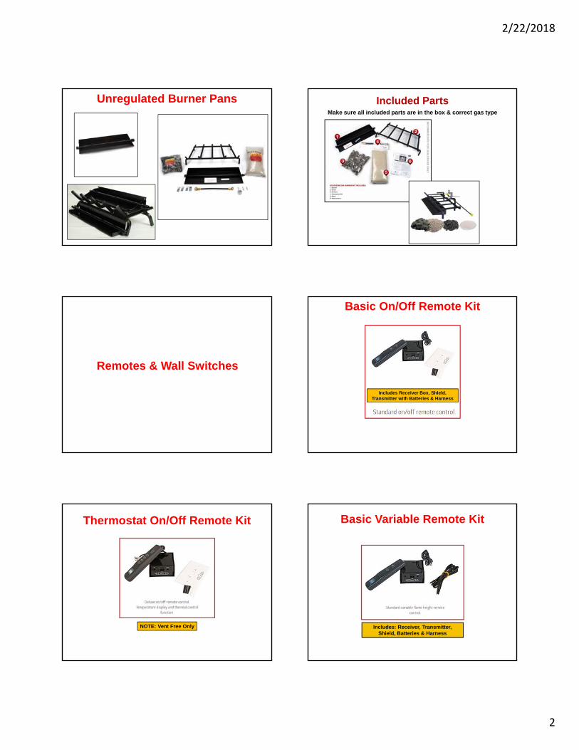
Unregulated Burner Pans Included PartsMake sure all included parts are in the box & correct gas type
Remotes & Wall Switches
Basic On/Off Remote Kit
Includes Receiver Box, Shield, Transmitter with Batteries & Harness
Thermostat On/Off Remote Kit
NOTE: Vent Free Only
Basic Variable Remote Kit
Includes: Receiver, Transmitter, Shield, Batteries & Harness

2/22/2018
3
Variable Thermostat Remote Kit
NOTE: Vent Free Only
On/Off Wall Switches
Applicable For Millivolt Automatic Pilot Valves:
NOTE: Vent Free & Vented
On/Off One Hour Timers
Applicable For Millivolt Control Pilot Valves Only
NOTE: Vent Free & Vented
Variable Wall Switches
Variable Wall Switches Include Rocker Switch & Battery Pack
NOTE: Vent Free & Vented
Vent Free Burners
• Certified Heating Appliance Z21.11.2B‐2010
• Equipped with An Oxygen Depletion Sensor (ODS)
• Use in Listed Solid‐Fuel Burning or Vent Free Firebox
• Active Natural Flames & Glowing Embers For Realism On Most Sets.
• 99% Heating Efficiency Which Means Less Gas
• Available for LP or NAT Gas
• Logs or Contemporary Glass Styles to Choose From
Vent Free Burner Features
2/22/2018
4
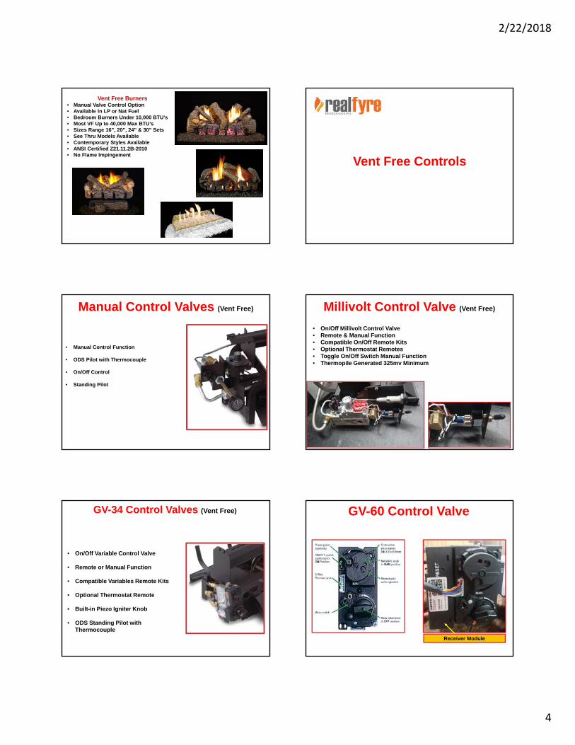
Vent Free Burners• Manual Valve Control Option• Available In LP or Nat Fuel• Bedroom Burners Under 10,000 BTU’s• Most VF Up to 40,000 Max BTU’s • Sizes Range 16”, 20”, 24” & 30” Sets• See Thru Models Available• Contemporary Styles Available • ANSI Certified Z21.11.2B-2010• No Flame Impingement
Vent Free Controls
Manual Control Valves (Vent Free)
• Manual Control Function
• ODS Pilot with Thermocouple
• On/Off Control
• Standing Pilot
Millivolt Control Valve (Vent Free)
• On/Off Millivolt Control Valve• Remote & Manual Function• Compatible On/Off Remote Kits• Optional Thermostat Remotes• Toggle On/Off Switch Manual Function• Thermopile Generated 325mv Minimum
GV-34 Control Valves (Vent Free)
• On/Off Variable Control Valve
• Remote or Manual Function
• Compatible Variables Remote Kits
• Optional Thermostat Remote
• Built-in Piezo Igniter Knob
• ODS Standing Pilot with Thermocouple
GV-60 Control Valve
Receiver Module

2/22/2018
5
GV-60 Features
Vent Free Electronic IPI System
Battery Operated 6 Volt System
“On Demand Pilot” Electronic Ignition System
Defaults to Manual Mode After Ignition
Flame Height Control
“Learns the Room System” Measures Room Temp & Compares it To Set-Point Temperature.
Remote Transmitter Sends Signal Every 4 Minutes to the receiver
Features:
GV-60 System Features
• Low Battery Receiver: Low battery power in the receiver, the system shuts off the fire completely.
• 6-Hour No Motor Movement: Manual/Temp/Timer Modes= The valve will turn to pilot if there is no change in flame height for a 6 hour period.
Temp/Timer Mode= If the ambient room temp changes, the flame height will adjust automatically to maintain set temp and the fire will continue to function normally. Valve will turn to pilot flame if the set temp & ambient temp remain the same over a 6 hour period.
Burner Installation Procedures
Gas Rated Tape or Pipe Compound on pipe thread fittings Only (Not on flared Fittings)
MFL Male Flare Fitting
½” NPT Rigid Pipe Thread
FPT Female Pipe Taper/Thread
NPT= (National Pipe Thread) FPT= Female Pipe Taper Both Require Joint Sealing Compounds or Joint Tape. US Standard.
Safety Pilot Kit Installation
Installing Flame Diverter
2/22/2018
6
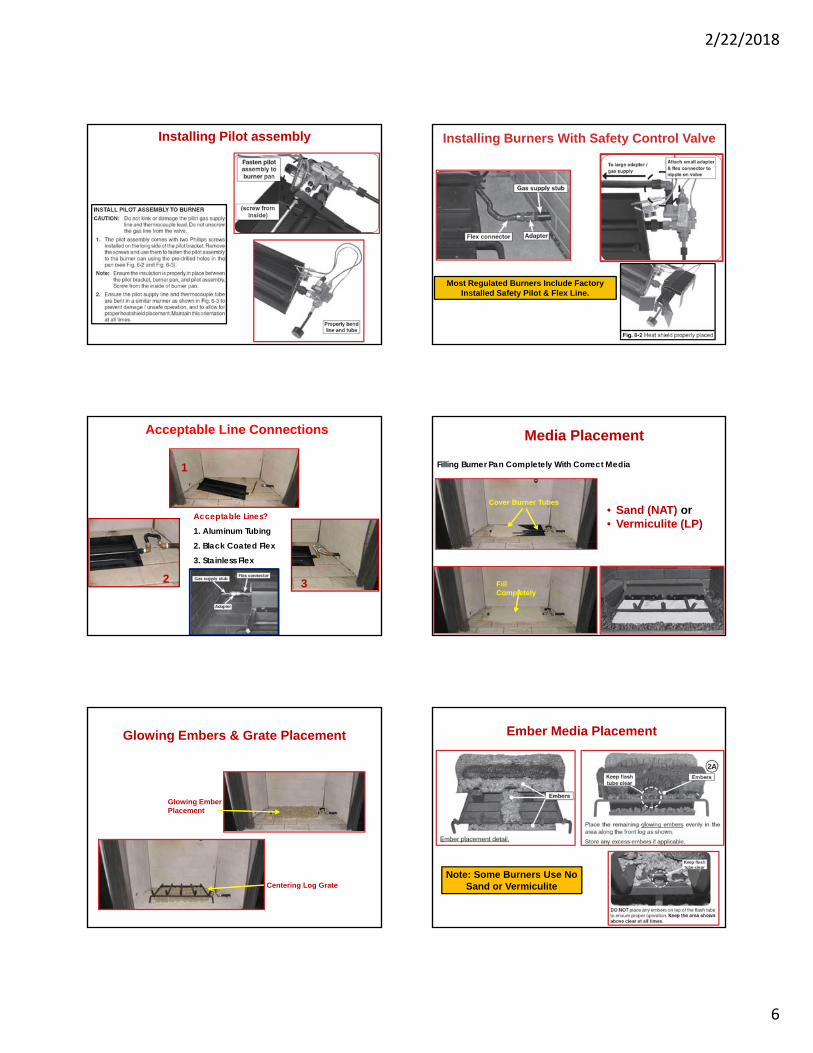
Installing Pilot assembly Installing Burners With Safety Control Valve
Most Regulated Burners Include Factory Installed Safety Pilot & Flex Line.
Acceptable Lines?1. Aluminum Tubing
2. Black Coated Flex3. Stainless Flex
1
2 3
Acceptable Line Connections Media Placement
Filling Burner Pan Completely With Correct Media
Fill Completely
• Sand (NAT) or• Vermiculite (LP)
Cover Burner Tubes
Glowing Embers & Grate Placement
Glowing Ember Placement
Centering Log Grate
Ember Media Placement
Note: Some Burners Use No Sand or Vermiculite
2/22/2018
7
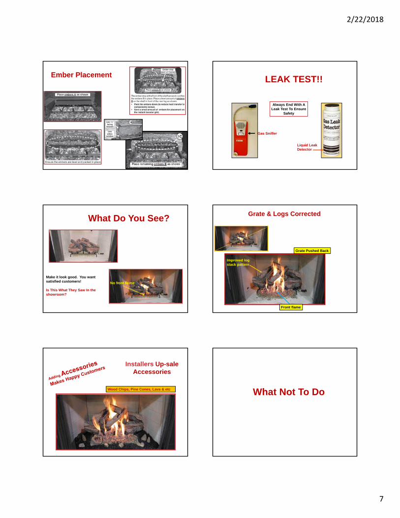
Ember Placement LEAK TEST!!
Always End With A Leak Test To Ensure
Safety
Gas Sniffer
Liquid Leak Detector
What Do You See?
No front flame Make it look good. You want satisfied customers!
Is This What They Saw In the showroom?
Grate & Logs Corrected
Grate Pushed Back
Improved log stack pattern
Front flame
Installers Up-sale Accessories
Wood Chips, Pine Cones, Lava & etc. What Not To Do
2/22/2018
8
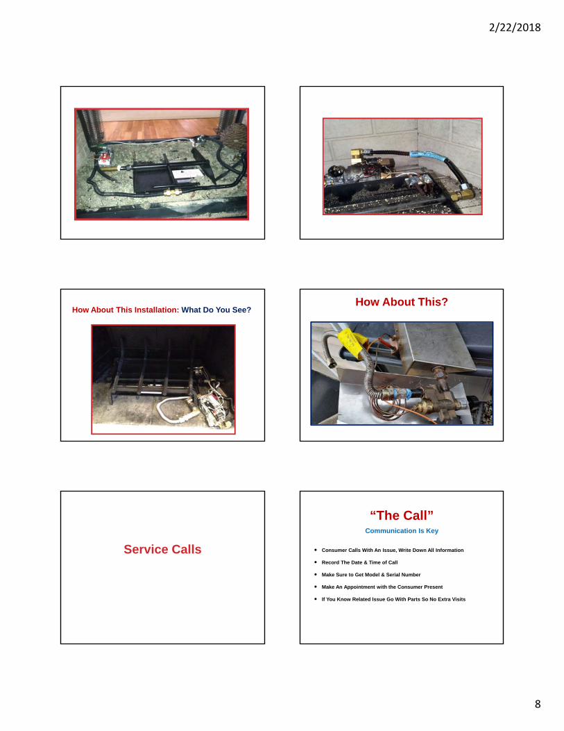
How About This Installation: What Do You See?How About This?
Service Calls
“The Call”Communication Is Key
Consumer Calls With An Issue, Write Down All Information
Record The Date & Time of Call
Make Sure to Get Model & Serial Number
Make An Appointment with the Consumer Present
If You Know Related Issue Go With Parts So No Extra Visits
2/22/2018
9
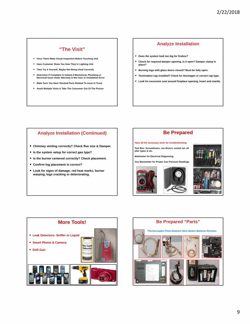
“The Visit”
Once There Make Visual Inspection Before Touching Unit
Have Customer Show You How They’re Lighting Unit
Then Try It Yourself, Maybe Not Being Used Correctly
Determine If Complaint Is Indeed A Mechanical, Plumbing or Electrical Issue Under Warranty & Not User or Installation Error
Make Sure You Have Stocked Parts Related To Issue In Truck
Avoid Multiple Visits & Take The Consumer Out Of The Picture
Analyze Installation
Does the system look too big for firebox?
Check for required damper opening. Is it open? Damper clamp in place?
Burning logs with glass doors closed? Must be fully open.
Termination cap installed? Check for blockages or correct cap type.
Look for excessive soot around fireplace opening, insert and mantle.
Analyze Installation (Continued)
Chimney venting correctly? Check flue size & Damper.
Is the system setup for correct gas type?
Is the burner centered correctly? Check placement.
Confirm log placement in correct?
Look for signs of damage; red heat marks, burner warping, logs cracking or deteriorating.
Be Prepared
Have all the necessary tools for troubleshooting:
Tool Box: Screwdrivers, nut drivers, socket set, all plier types & etc.
Multimeter for Electrical Diagnosing.
Gas Manometer for Proper Gas Pressure Readings.
More Tools!
Leak Detectors: Sniffer or Liquid
Smart Phone & Camera:
Drill Gun
Be Prepared “Parts”
Thermocouples-Pilots-Modules-Valve Bodies-Batteries-Remotes
2/22/2018
10
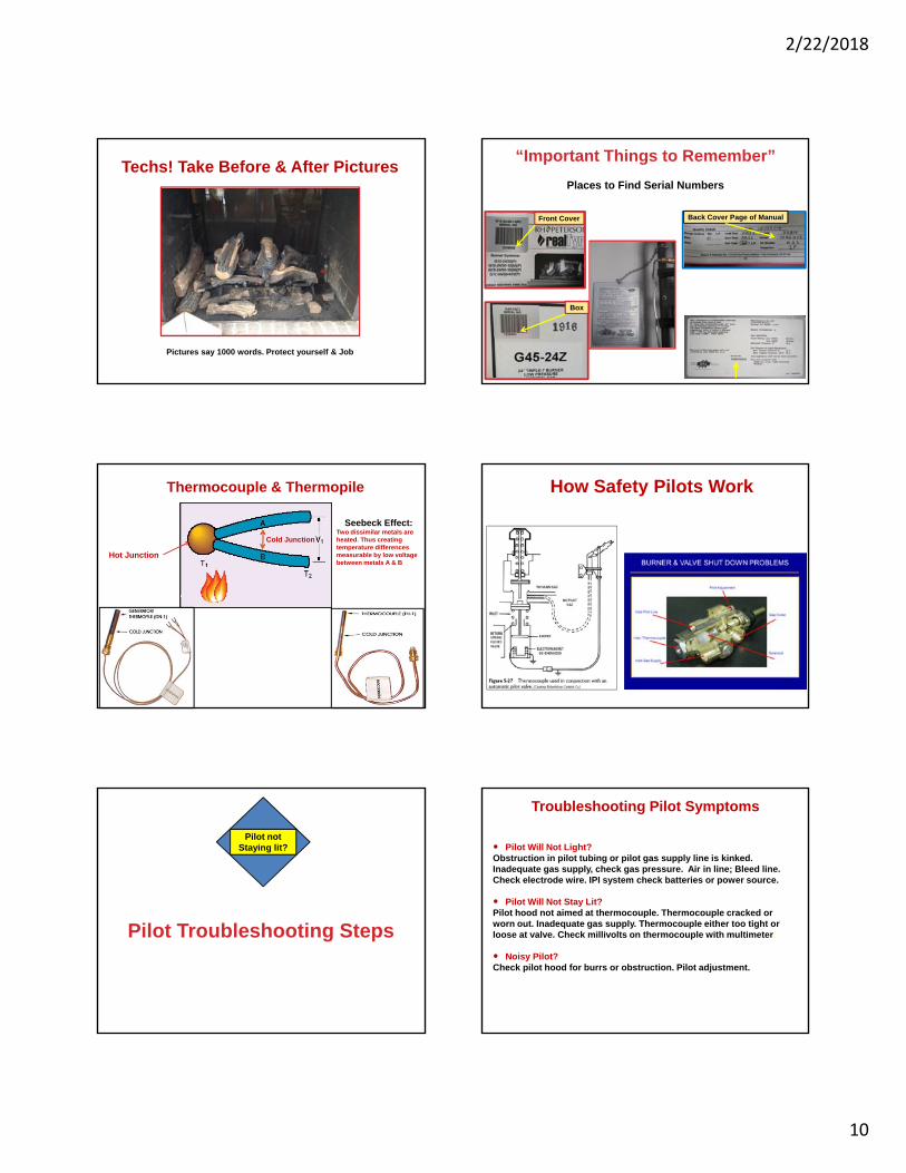
Techs! Take Before & After Pictures
Pictures say 1000 words. Protect yourself & Job
“Important Things to Remember”
Places to Find Serial Numbers
Back Cover Page of ManualFront Cover
Box
Thermocouple & Thermopile
Hot Junction
Cold Junction
Seebeck Effect:Two dissimilar metals are heated. Thus creating temperature differences measurable by low voltage between metals A & B
How Safety Pilots Work
Pilot Troubleshooting Steps
Pilot not Staying lit?
Troubleshooting Pilot Symptoms
Pilot Will Not Light? Obstruction in pilot tubing or pilot gas supply line is kinked. Inadequate gas supply, check gas pressure. Air in line; Bleed line. Check electrode wire. IPI system check batteries or power source.
Pilot Will Not Stay Lit? Pilot hood not aimed at thermocouple. Thermocouple cracked or worn out. Inadequate gas supply. Thermocouple either too tight or loose at valve. Check millivolts on thermocouple with multimeter.
Noisy Pilot? Check pilot hood for burrs or obstruction. Pilot adjustment.
2/22/2018
11
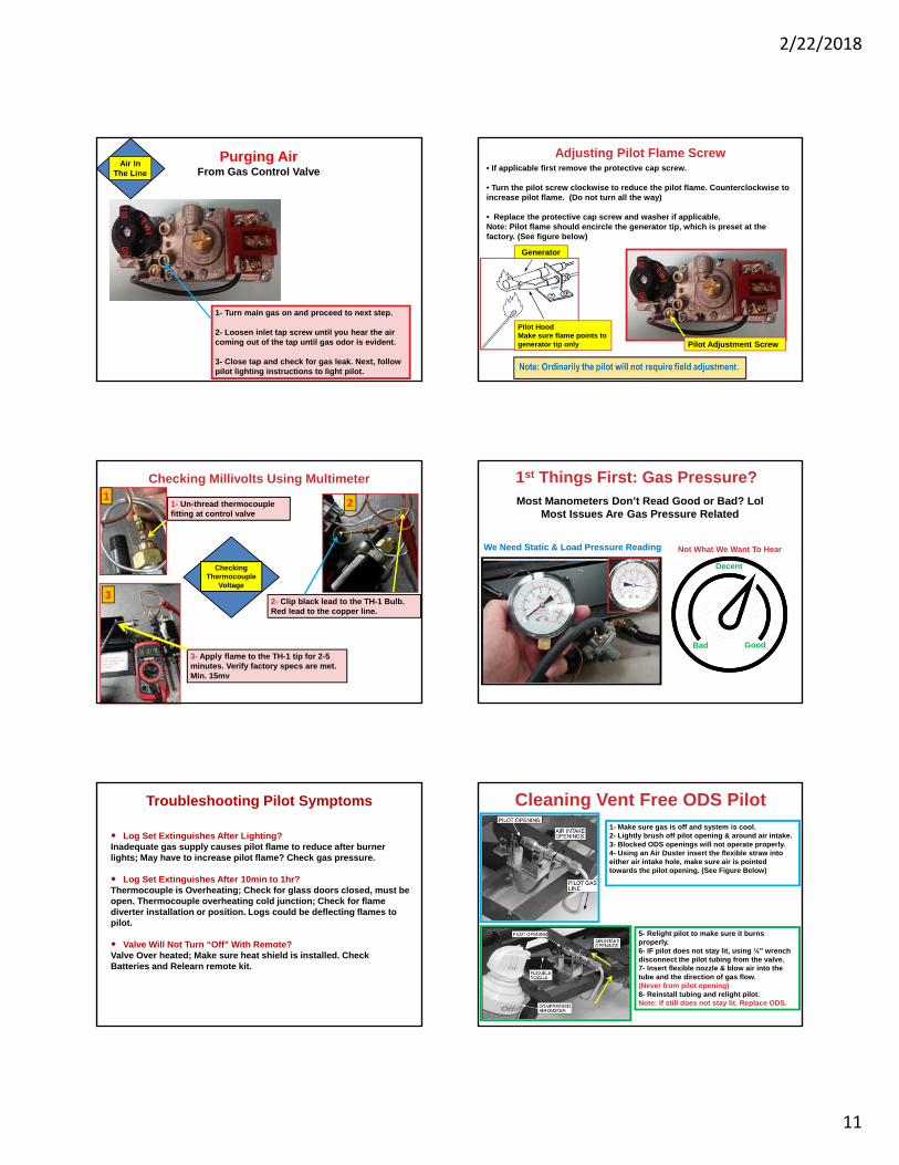
Purging AirFrom Gas Control Valve
1- Turn main gas on and proceed to next step.
2- Loosen inlet tap screw until you hear the air coming out of the tap until gas odor is evident.
3- Close tap and check for gas leak. Next, follow pilot lighting instructions to light pilot.
Air In The Line
• If applicable first remove the protective cap screw.
• Turn the pilot screw clockwise to reduce the pilot flame. Counterclockwise to increase pilot flame. (Do not turn all the way)
• Replace the protective cap screw and washer if applicable.Note: Pilot flame should encircle the generator tip, which is preset at the factory. (See figure below)
Generator
Pilot HoodMake sure flame points to generator tip only Pilot Adjustment Screw
Adjusting Pilot Flame Screw
Checking Millivolts Using Multimeter1
1- Un-thread thermocouple fitting at control valve
2- Clip black lead to the TH-1 Bulb. Red lead to the copper line.
2
3
3- Apply flame to the TH-1 tip for 2-5 minutes. Verify factory specs are met. Min. 15mv
Checking Thermocouple
Voltage
1st Things First: Gas Pressure?Most Manometers Don’t Read Good or Bad? Lol
Most Issues Are Gas Pressure Related
Bad Good
Decent
Not What We Want To HearWe Need Static & Load Pressure Reading
Troubleshooting Pilot Symptoms
Log Set Extinguishes After Lighting?Inadequate gas supply causes pilot flame to reduce after burner lights; May have to increase pilot flame? Check gas pressure.
Log Set Extinguishes After 10min to 1hr? Thermocouple is Overheating; Check for glass doors closed, must be open. Thermocouple overheating cold junction; Check for flame diverter installation or position. Logs could be deflecting flames to pilot.
Valve Will Not Turn “Off” With Remote? Valve Over heated; Make sure heat shield is installed. Check Batteries and Relearn remote kit.
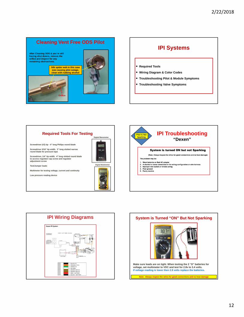
Cleaning Vent Free ODS Pilot1- Make sure gas is off and system is cool.2- Lightly brush off pilot opening & around air intake.3- Blocked ODS openings will not operate properly.4- Using an Air Duster insert the flexible straw into either air intake hole, make sure air is pointed towards the pilot opening. (See Figure Below)
5- Relight pilot to make sure it burns properly.6- IF pilot does not stay lit, using ¼” wrench disconnect the pilot tubing from the valve.7- Insert flexible nozzle & blow air into the tube and the direction of gas flow. (Never from pilot opening)8- Reinstall tubing and relight pilot. Note: If still does not stay lit. Replace ODS.
2/22/2018
12
Cleaning Vent Free ODS Pilot
After Cleaning ODS & you’re still having shut downs, remove the orifice and inspect for any remaining obstructions.
Silk spider web in this case was causing pilot outage, clean with rubbing alcohol
Orifice
IPI Systems
Required Tools
Wiring Diagram & Color Codes
Troubleshooting Pilot & Module Symptoms
Troubleshooting Valve Symptoms
Required Tools For Testing
Screwdriver (#2) tip - 4" long Philips round blade
Screwdriver 3/16" tip width. 3" long slotted narrow round blade for pressure taps
Screwdriver, 1/4" tip width. 4" long slotted round blade to access regulator cap screw and regulator adjustment screw
Test/Jumper leads
Multimeter for testing voltage, current and continuity
Low pressure reading device
Digital Multimeter
Digital Manometer
IPI Troubleshooting“Dexen”
Pilot Is Not Sparking
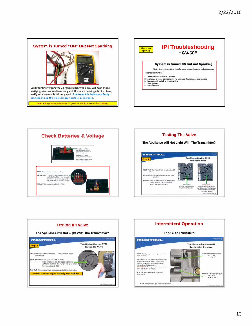
IPI Wiring Diagrams System is Turned “ON” But Not Sparking
Make sure leads are on tight. When testing the 2 “D” batteries for voltage, set multimeter to VDC and test for 2.8v to 3.4 volts. If voltage reading is lower then 2.8 volts replace the batteries.
Note: Always inspect the wires for good connections and no heat damage
2/22/2018
13
System is Turned “ON” But Not Sparking
Verify continuity from the 2 brown switch wires. You will hear a tone verifying wires connections are good. If you are hearing a broken tone, verify wire harness is fully engaged. If no tone, this indicates a faulty connection and the wire harness needs to be replaced.
Note: Always inspect the wires for good connections and no heat damage
IPI Troubleshooting“GV-60”
Pilot Is Not Sparking
Check Batteries & Voltage Testing The Valve
The Appliance will Not Light With The Transmitter?
Step 1
Step 2
Testing IPI Valve
The Appliance will Not Light With The Transmitter?
Result: If Burner Lights Manually, Bad Module?
Intermittent Operation
Test Gas Pressure

2/22/2018
14
Burner Troubleshooting Steps
Burner Not Staying Lit
Troubleshooting Burner Symptoms
• Burner Shutting Down? Check incoming gas pressure under load; Check manual for gas requirements. Check for other appliances on same gas line, could drop gas pressure to set. Check damper size requirement. Log set too big.
• Low Flame Height? Check gas pressure. Propane tank may be low.
• Not Burning Evenly? Burner orifice clogged; Clean orifice. Check for sand or vermiculite compaction; Loosen with screwdriver or hack saw blade.
• Remote Not Communicating? Check batteries. Relearn remote kit. Remote receiver overheating; May be able to hear audible beeps at shut down.
Remote Receiver PlacementBurner Shut Down
6”-8” Min. Clearance from burner needed
Note: Never place receiver in back of firebox due to overheating, always place forward of the burner as shown above. (Overheating Receiver Will Shut Unit Down)
Remote Not Turning On Burner?
• Check Switch Position (Remote)• Check Batteries For
Voltage & Placement• Check Wiring• Check Receiver Location in Firebox• Check Receivers Heatshield
is being used.
No Communication
Switch Heat Shield
No Communication
1- Make sure switch is on “Remote”Code will not learn in On or Off position.2- Push & release the learn button. Should hear a beeping sound.3- Next, press & release any button on the transmitter. A change in the beeping pattern at the receiver indicates transmitter’s code has been programmed into the receiver.
Re-Learning Remote Kit No
Communication
01V Remote• Receiver Module 4 AA (6
Volt) (AR-01V-2)• Transmitter 9 Volt Battery
(AT-01V-2)
2/22/2018
15
My Bottom Burner Is Not Lighting?Ember
Placement
• Ember Burner Will Not Light Without Glowing Embers• Embers Create Back Pressure For Combustion
Ever Have This Happen?
No Embers
Troubleshooting Burner Symptoms
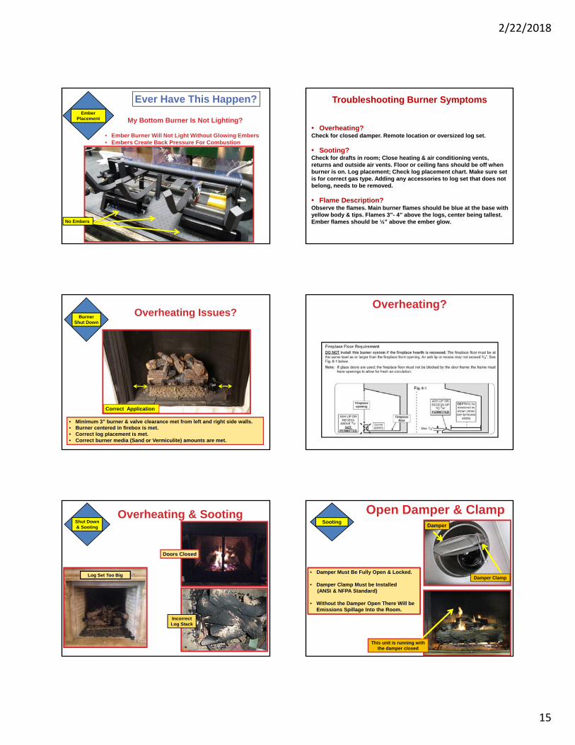
• Overheating? Check for closed damper. Remote location or oversized log set.
• Sooting? Check for drafts in room; Close heating & air conditioning vents, returns and outside air vents. Floor or ceiling fans should be off when burner is on. Log placement; Check log placement chart. Make sure set is for correct gas type. Adding any accessories to log set that does not belong, needs to be removed.
• Flame Description? Observe the flames. Main burner flames should be blue at the base with yellow body & tips. Flames 3”- 4” above the logs, center being tallest. Ember flames should be ¼” above the ember glow.
Overheating Issues?
• Minimum 3” burner & valve clearance met from left and right side walls.• Burner centered in firebox is met.• Correct log placement is met.• Correct burner media (Sand or Vermiculite) amounts are met.
Burner Shut Down
Correct Application
Overheating?
Shut Down& Sooting
Overheating & Sooting
Doors Closed
Log Set Too Big
Incorrect Log Stack
Open Damper & ClampSooting
• Damper Must Be Fully Open & Locked.
• Damper Clamp Must be Installed (ANSI & NFPA Standard)
• Without the Damper Open There Will be Emissions Spillage Into the Room.
Damper
Damper Clamp
This unit is running with the damper closed
2/22/2018
16
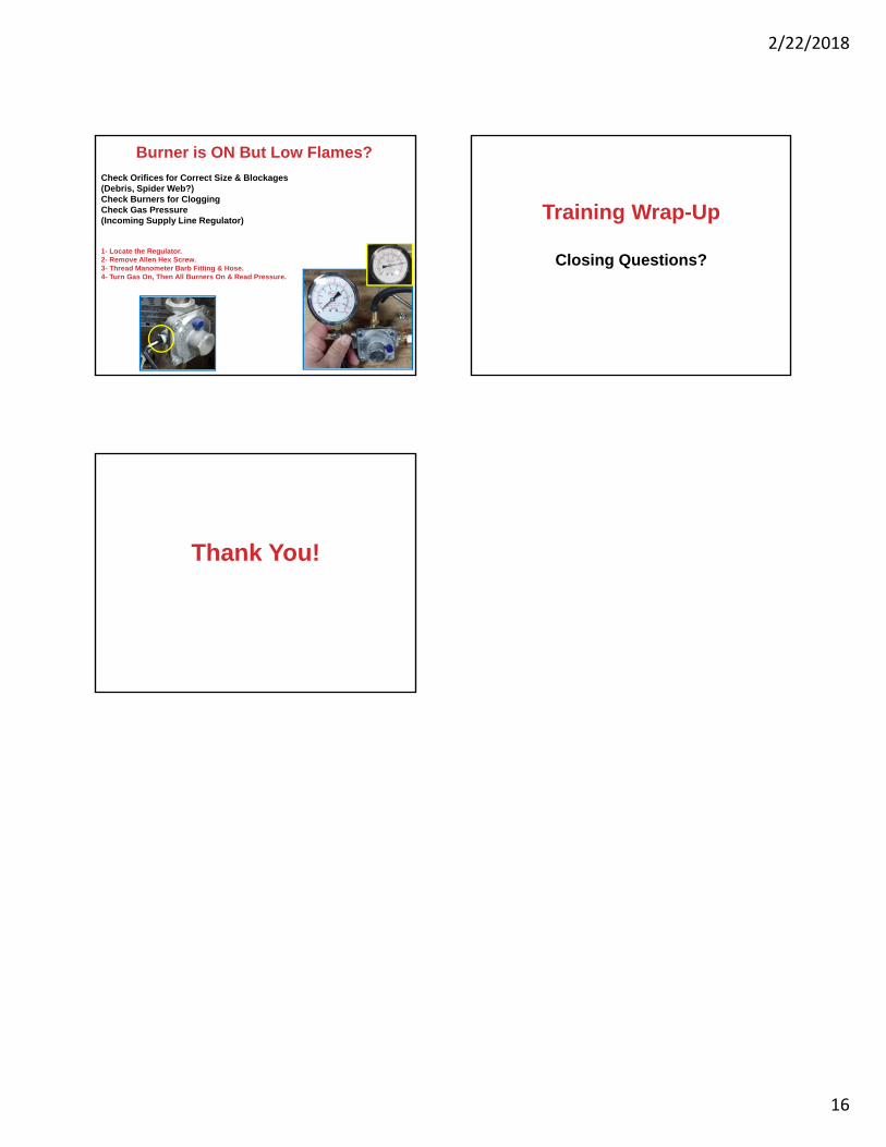
Burner is ON But Low Flames?
Check Orifices for Correct Size & Blockages (Debris, Spider Web?)Check Burners for CloggingCheck Gas Pressure (Incoming Supply Line Regulator)
1- Locate the Regulator.2- Remove Allen Hex Screw.3- Thread Manometer Barb Fitting & Hose.4- Turn Gas On, Then All Burners On & Read Pressure.
Training Wrap-Up
Closing Questions?
Thank You!