gas tank leakage detector and monitoring system … · kewaspadaan berterusan diperlukan dalam...
TRANSCRIPT

i
GAS TANK LEAKAGE
DETECTOR AND MONITORING
SYSTEM
MIMI HARYANI BINTI TASANI
BACHELOR OF COMPUTER SCIENCE
(INTERNET COMPUTING) WITH HONOURS
UNIVERSITY SULTAN ZAINAL ABIDIN (UNISZA)
2019

ii
DECLARATION
I hereby declare that this report is based on my original work except for
quotations and citations, which have been duly acknowledged. I also declare that
it has not been previously or concurrently submitted for any other degree at
Universiti Sultan Zainal Abidin or other institutions.
Name:..Mimi Haryani binti Tasani……
Date:……..26th December 2019…...….

iii
CONFIRMATION
This is to confirm that gas tank leakage detector and monitoring system was prepared
by Mimi Haryani binti Tasani matric number BTCL17047147. This project have
checked and from our perspective this project research have fulfilled the condition
to be recognized for the level of Bachelor of Computer Science of Internet
Computing. The research conducted and writing this report under my guidance
supervision.
Name: DR. AZRUL AMRI JAMAL
Date : ................................................

iv
ACKNOWLEDGEMENTS
In the name of Allah, Most Gracious, and the Most Merciful. Alhamdulillah
with blessed from Allah that allow me to complete the final project which is Gas Tank
Leakage Detector and Monitoring System.
Here I would like to express my sincere thanks and dedicate to my beloved
supervisor of this Final Year Project, Dr Azrul Amri bin Jamal for this suggestion or
ideas and also the valuable guidance and advice that encourage me to complete the
system successfully.
Sincere thanks to all my friends for their kindness and moral support. Last but
not least, my deepest gratitude to my beloved parents for their prayers and
encouragement. For those who are indirectly contributing, your kindness means a lot to
me.
Thank You.
v
ABSTRACT
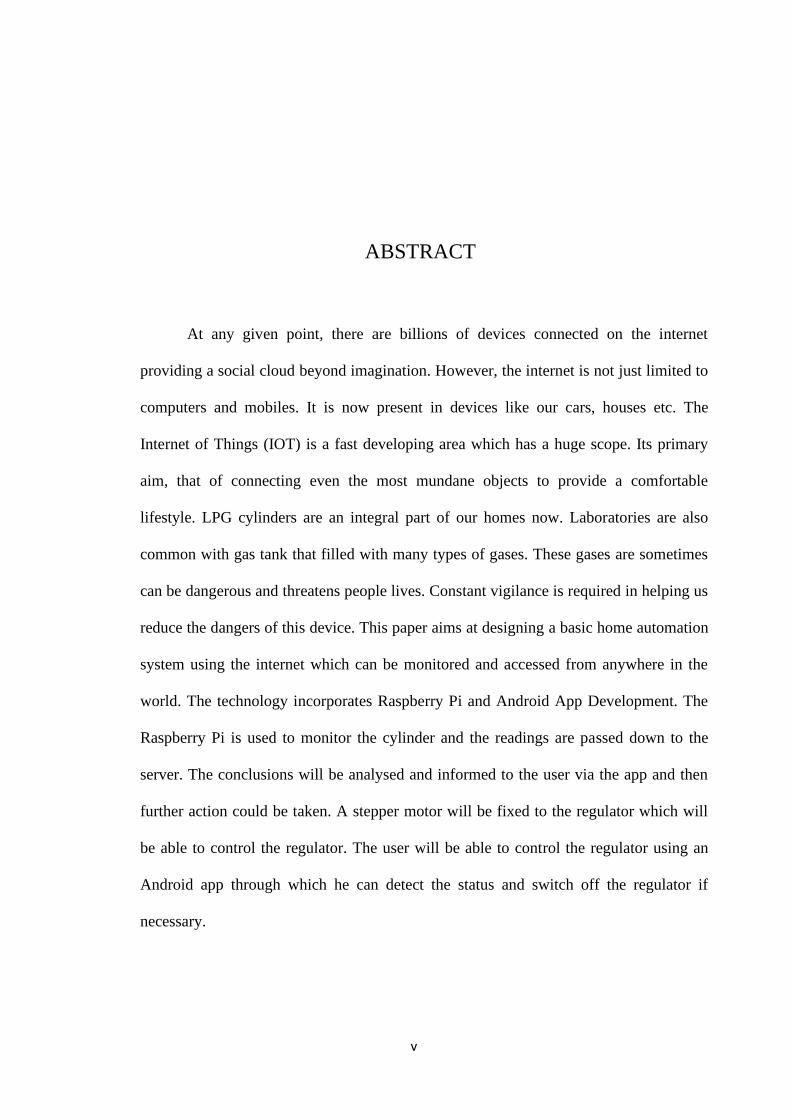
At any given point, there are billions of devices connected on the internet
providing a social cloud beyond imagination. However, the internet is not just limited to
computers and mobiles. It is now present in devices like our cars, houses etc. The
Internet of Things (IOT) is a fast developing area which has a huge scope. Its primary
aim, that of connecting even the most mundane objects to provide a comfortable
lifestyle. LPG cylinders are an integral part of our homes now. Laboratories are also
common with gas tank that filled with many types of gases. These gases are sometimes
can be dangerous and threatens people lives. Constant vigilance is required in helping us
reduce the dangers of this device. This paper aims at designing a basic home automation
system using the internet which can be monitored and accessed from anywhere in the
world. The technology incorporates Raspberry Pi and Android App Development. The
Raspberry Pi is used to monitor the cylinder and the readings are passed down to the
server. The conclusions will be analysed and informed to the user via the app and then
further action could be taken. A stepper motor will be fixed to the regulator which will
be able to control the regulator. The user will be able to control the regulator using an
Android app through which he can detect the status and switch off the regulator if
necessary.

vi
ABSTRACT
Di mana-mana titik tertentu, terdapat berbilion-bilion peranti yang
disambungkan di internet menyediakan sosial awan melampaui imaginasi. Walau
bagaimanapun, internet tidak hanya terhad kepada komputer dan telefon bimbit. Ia kini
hadir dalam peranti seperti kereta, rumah dan lain-lain. Internet Perkara (IOT) adalah
kawasan pembangunan yang cepat yang mempunyai skop yang besar. Matlamat
utamanya, iaitu menyambungkan objek yang paling biasa untuk disampaikan gaya
hidup yang selesa. Silinder LPG adalah sebahagian daripada rumah kami sekarang.
Makmal juga biasa dengan tangki gas yang dipenuhi dengan banyak jenis gas. Gas-gas
ini kadang-kadang boleh membahayakan dan mengancam kehidupan manusia.
Kewaspadaan berterusan diperlukan dalam membantu kami mengurangkan bahaya
peranti ini. Makalah ini bertujuan untuk merekabentuk automasi rumah asas sistem
yang menggunakan internet yang boleh dipantau dan diakses dari mana saja di dunia.
Teknologi menggabungkan Raspberry Pi dan Android App Pembangunan. Raspberry Pi
digunakan untuk memantau silinder dan bacaan dibuang ke pelayan. Kesimpulan akan
dianalisis dan dimaklumkan kepada pengguna melalui aplikasi dan kemudian tindakan
selanjutnya boleh dilakukan diambil. Motor stepper akan ditetapkan kepada pengawal
selia yang akan dapat mengawal pengawal selia. Pengguna akan dapat mengawal
pengawal selia menggunakan Android aplikasi di mana dia boleh mengesan status dan
suis off the regulator jika perlu.

vii
TABLE OF CONTENTS
Page
DECLARATION ii
CONFIRMATION iii
ACKNOWLEDGEMENT iv
ABSTRACT vii
CONTENTS viii
LIST OF TABLES xii
LIST OF FIGURES xiii
LIST OF ABBREVIATIONS xvi
LIST OF APPENDICES xvii
CHAPTER I INTRODUCTION
1.1 Project Background 1
1.2 Problem Statement 2
1.3 Objectives 4
1.4 Scopes 4
1.5 Limitation 5

viii
1.6 Expected Result 5
CHAPTER II LITERATURE REVIEW
2.1 Introduction 6
2.2 Research 6
2.3 Summary 9
CHAPTER III METHODOLOGY
3.1 Introduction 10
3.2 Prototyping model 11
3.3 Phase 1: Requirement Gathering 12
3.4 Phase 2: Quick Design 12
3.5 Phase 3: Prototype Evaluated 13
3.6 Phase 4: Refined the End Functionality 13
3.7 Requirement 13
3.7.1 Hardware Requirement 14
3.7.2 Software Requirement 15
3.8 Framework Design 16

ix
3.9 Process Model 17
3.9.1 Data Flow Diagram (DFD)
17
3.10 Data Model
17
3.10.1 Entity Relationship Diagram (ERD)
17
3.10.2 Data Dictionary
18
3.11 Proof of Concept
22
3.12 Solution Complexity
29
3.12.1 Hybrid Technique
29
3.12.2 Algorithm
30
3.13 Summary
30
REFERENCES 31
APPENDIX 33

x
LIST OF TABLES
TABLE TITLE PAGE
3.1 List Of Hardware Requirement 14
3.2 List Of Software Requirement 15
3.3 Data Dictionary For Staff 19
3.4 Data Dictionary for Admin 19
3.5 Data Dictionary for Department 20
3.6 Data Dictionary for Sensor Monitor 20
3.7 Data Dictionary for Gas Tank 20

xi
LIST OF FIGURES
FIGURE TITLE PAGE
3.1 Prototyping Model 11
3.2 Framework 16
3.3 Data Flow Diagram 17
3.4 Entity Relationship Diagram 18
3.5 Prototype front page for admin 22
3.6 Prototype of front page for staff 23
3.7 Prototype of tank list for Admin and Staff 24
3.8 Prototype gas tank details for Admin and Staff 24
3.9 Prototype of Sensor list page for Admin and Staff 25
3.10 Prototype of Sensor details for Admin and Staff 25
3.11 Prototype of UCL Staff list for Admin 26
3.12 Prototype of Staff profile for admin 26
3.13 Prototype of Leakage History List 27
3.14 Prototype of Alert Message on website 28
3.15 Prototype of Alert Message on mobile phone 28
3.16 Algorithm of solution complexity of system 30

xii
LIST OF ABBREVIATIONS
DFD Data Flow Diagram
ERD Entity Relationship Diagram
FYP Final Year Project
xiii
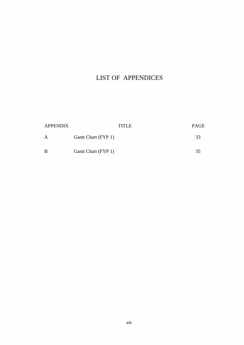
LIST OF APPENDICES
APPENDIX TITLE PAGE
A Gantt Chart (FYP 1)
33
B Gantt Chart (FYP 1)
35

1
CHAPTER I
INTRODUCTION
1.1 Introduction
Gases employed in the semiconductor industries are required to have high
purity levels, and also sensitive monitoring and analytical techniques, not of the
laboratory level, but of the level employable on the spot, have been strongly desired.
Whenever flammable or toxic gases are used, it is possible that a gas could be leaking
into the room or contiguous areas. Monitoring for the presence and concentration of
these gases is a prudent safety precaution.
Modern laboratories use a number of gases as part of their daily operations. A
number of gases are used in laboratories to support various applications such as
Chromatography (GC and LC-MS) Spectroscopy, ELSD and Sample Preparation.
Laboratories use a wide range of gases including carbon dioxide, enriched oxygen and
inert gases including helium, argon and nitrogen. All of these gases carry risks.
This project is focus on nearest lab in UniSZA Tembila which is FBIM
laboratory. There few gases used which are carbon dioxide, oxygen, nitrogen and

2
argon gases. This system will sensing the argon or nitrogen gas leak and will display
on computer monitor system through ethernet. This system can remotely control even
there is no person on duty and will giving alert if there any leakage and giving the
exact place where the leak happens.
Since there are dangerous gases used, gas leakage detector is very important for
multiple laboratory purposes. It is a process that can identify potential hazardous gas
leak using sensors. These sensors usually employ an audible alarm to alert people
when a dangerous gas has been detected.
1.2 Problem Statement
Gases employed in the semiconductor industries are required to have high
purity levels, and also sensitive monitoring and analytical techniques, not of the
laboratory level, but of the level employable on the spot, have been strongly desired.
Whenever flammable or toxic gases are used, it is possible that a gas could be leaking
into the room or contiguous areas. Monitoring for the presence and concentration of
these gases is a prudent safety precaution.
Modern laboratories use a number of gases as part of their daily operations. A
number of gases are used in laboratories to support various applications such as
Chromatography (GC and LC-MS) Spectroscopy, ELSD and Sample Preparation.
Laboratories use a wide range of gases including carbon dioxide, enriched oxygen and
inert gases including helium, argon and nitrogen. All of these gases carry risks.
This project is focus on nearest lab in UniSZA Tembila which is FBIM
laboratory. There few gases used which are carbon dioxide, oxygen, nitrogen and
argon gases. This system will sensing the argon or nitrogen gas leak and will display
on computer monitor system through ethernet. This system can remotely control even

3
there is no person on duty and will giving alert if there any leakage and giving the
exact place where the leak happens.
Since there are dangerous gases used, gas leakage detector is very important for
multiple laboratory purposes. It is a process that can identify potential hazardous gas
leak using sensors. These sensors usually employ an audible alarm to alert people
when a dangerous gas has been detected.

4
1.3 Objectives
Internal leakage and external leakage should be avoided absolutely for security
sake, since they can cause accidents if they occur when highly reactive gases are being
analyzed. Thus, to avoid this incidents a gas leakage detector system is implemented to
achieve some of this objectives.
1) To study about gas tank monitoring method.
2) To design a gas leakage detector through regulator pressure that easier to
monitor.
3) To implement a gas tank leakage detector which complete with alert alarm
and screen monitoring system that can show the specific place of gas
leakage and and at the same time the person on duty can fix the leak as
soon as possible before it getting worst.
1.4 Scopes
This system focus on any places that use flammable or inert gas tank. For now it
focus on Fakulti Biosumber & Industri Makanan (FBIM), University Sultan Zainal
Abidin (UniSZA) or UniSZA Central Lab (UCL) laboratories. Admin also includes to
monitor the tank gas monitoring and leakage system.
5
1.5 Limitation
This system for detecting the gas leakage only for gas tank that install with
pressure regulator. Since this IoT system only use pressure sensor as the leakage
detector.
1.6 Expected Result
Expectations is when the system should be capable of giving a warning of both
the presence and the general location of an accident accumulation of flammable gases,
in order to initiate one or more of the following actions, either automatically or under
manual control. This system is complete with IOT system which is provide better
performance which can monitor and fix easily. This system also can be monitored
remotely.

6
CHAPTER II
LITERATURE REVIEW
2.1 Introduction
Expectations is when the system should be capable of giving a warning of
both the presence and the general location of an accident accumulation of
flammable gases, in order to initiate one or more of the following actions, either
automatically or under manual control. This system is complete with IOT system
which is provide better performance which can monitor and fix easily. This system
also can be monitored remotely.
2.2 Research
Based on study, there are few ways to detect gas leakage . For example
detect gas by using image. An infrared source consisting of a fibre coupled InGaAs
laser diode (LASER 2000, LAS-022527) is used to illuminate a high-speed DMD
(Vialux, V-7000) [Gibson, 2017]. There is also a system which uses PZT sensor as
gas detectors. Lead zirconate titanate (PZT) sensors were used to detect the arrival

7
time of negative pressure wave (NPW) associated with leakage in a model pipeline
[Zhu J, 2017].
There is also gas leakage detector that can detect earlier process of gas leak
before it happen for example an article mention about earlier gas detection and
alerting system were designed for detecting carbon monoxide and oxygen level in a
vehicle cabin [Jewel M, 2018]. System for sensing each chemical element is costly
and often unaffordable for small research labs. The main objective of our work is to
design a low-cost microcontroller-based gas and air quality detection and monitoring
system for nanofabrication labs. The system is capable of sensing common chemical
species in a fabrication lab like butane, IPA, and acetone. The amount of chemical
species and environmental conditions are shown on an LCD display continuously.
The analog sensor readings are transferred on a computer screen using an Ethernet
module. The system is customizable and sensors readings can be observed remotely
[Jewel M, 2018].
There are few gas sensors that used in existing gas detector for example
MQ137 and MiCS-6814 sensors will be annexed to the microcontroller to sense NH3
and NO2 gases in a fabrication lab [Jewel M, 2018]. Gas sensor MQ2 is a sensor that
detects gases, specifically hydrogen (H2), Liquid Petroleum Gas (LPG), Methane
(CH4), Carbon Monoxide (CO), Alcohol, Propane, Smoke at the atmosphere
[Iskandar, 2018]. MQ-4 gas sensor used to sense poisonous gas and has high
sensitivity to LPG and also response to natural gas [Wassim, 2017].
Since this project is focus only on fewer gases such as Carbon Dioxide(CO2),
Oxigen(O2), Argon(Ar) and Nitrogen(N2) gas. Inert gases, such as argon, do not
support human breathing and a leak of argon into the atmosphere can cause oxygen
levels to deplete, leading to asphyxiation. Normal air usually has an oxygen
concentration of 20.9%. A drop to 19% is enough for some people to suffer

8
physiological effects, whilst a drop to 10% can cause loss of consciousness or even
death. There are few systems that related with laboratory gases are using oxygen gas
sensor to sense the gases mentioned. For example since nitrogen does not have a
color or scent, gases like nitrogen and argon can deplete oxygen from the
environment and it will be seen through the level of oxygen gas by the sensor
[Carrino A, 2016].
If there are fires, a sensor called DHT11 will be used to detect fire
temperature. For example, it is used to sense a high temperature or positive change of
temperature and it will send a pulse to microcontroller and also send an alert message
through android apps and location via GPS through IOT to the nearest fire
station[Iskandar, 2018]. To give the real time response, Espresso lite V2.0 was used
as Wi-Fi module and Blynk act as software that use to display all the reading
[Iskandar,2018].
This IOT system will apply Arduino as the microcontroller for the physical
computing. Research found few articles that use Arduino as the microcontroller for
example Arduino Microcontroller is a source of open electronics prototyping
platform based on flexible, easy to use hardware and software and it is capable to
sense the environment by receiving input signals from different sensors and can
accordingly control different operations[Himanshu T., 2017]. Arduino Uno is also a
part of this project that acts as a microcontroller and espresso can use as Wi-Fi
module for example LPG leakage detector controlled by Arduino Uno using MQ-2
gas sensor to detect the presence of gas leakage and DHT-11 temperature sensor
[Iskandar, 2018]. The Arduino project provides the Arduino integrated development
environment (IDE), which is a crossplatform application written in the programming
language Java [Anandhakrishnan, 2017].
9
2.3 Summary
This chapter provides an overview of the concept of the application. Based on
research that has been made it show that literature review is one of the important parts
as we can use the technique from the current and existing system to develop the
proposed application. The technique is chosen based on the previous articles and
journal.

10
CHAPTER III
METHODOLOGY
3.1 Introduction
Methodology is defined as a set of procedures. The methodology that I used to
develop this gas leakage detector and monitoring system is prototyping model. This
model consist four phases that are applied in order to develop the application. This
model is also used to briefing more details about the four phases that involved in order
to develop this system inclusive the system requirement.
In this section will be described on the design of implementing the system. There
are two parts of design, which is system design and database design. For system design,
it contains of framework diagram, Data Flow Diagram (DFD). Besides that, for
database design, it consists Entity Relationship Diagram (ERD) and data dictionary.

11
3.2 Prototyping Model
Figure 3.1: Prototyping Model
The Prototyping Model is a systems development method in which a prototype
is built, tested, and then reworked until an acceptable prototype is finally accomplished
from which the complete system or product can now be developed. Thus, this model
works best in scenarios where not all of the project requirements are known in detail
ahead of time. This model is an iterative, trial-and-error process that takes place between
the developers and the users. Other than that, a prototype also is a model or a program
which is not based on exact planning but is an early approximation of the final product
or software system. There are 4 phases in the prototype model which are requirement
gathering, quick design, client evaluation, and refined the end functionality.
The advantages of prototyping model are the users can view their requirements
as prototypes as new requirements are being gathered. Besides, the prototyping model

12
has a flexible design and flexibility in development can be achieved and thus a more
accurate end product. Other than that, it also can reduce time and costs and of course,
there is a great involvement of users in software development. Consequently, the
requirements of the users are met to the greatest extent. A systems development life
cycle (SDLC) has three primary objectives which are to ensure that high-quality
systems are delivered, to provide strong management controls over the projects, and to
maximize the productivity of the systems developer.
3.3 Phase 1: Requirement Gathering
This is the first phase and there is no planning involved. Instead of that, this
application being considered by thinking what is needed for making the genuine product
that is going to be developed. This phase is carried out at the earliest stage of each cycle.
In this phase, Software Requirement Specification (SRS) is made. The user is
interviewed in order to know the requirements of the system. The process of gathering
requirements is usually more than simply asking the users what they need and writing
their answers down and also based on research and review on existing system. This is
to make sure there are no data that is left over to put in the project. For modification,
the data of the changes from the old evaluation are being saved and added into the new
system development.
3.4 Phase 2: Quick Design
When requirements gathering phase is done, a preliminary design or quick
design for the system is created. It is not a detailed design and includes only the prime

13
aspects of the system, which gives an idea of the system to the user. A quick design
helps in developing the prototype. The requirement acquired during planning and
requirement phase was analysed and transform into the design. There are some diagrams
such as Framework of the project, Context Diagram (CD), Data Flow Diagram (DFD)
level 0, Data Flow Diagram (DFD) level 1, Entity Relation Diagram (ERD) and Data
Dictionary.
3.5 Phase 3: Prototype Evaluated
Prototype evaluated phase is where developer show their prototype to the client
and for this proposed project, it is show to the panel. The panel will evaluated is it satisfy
or not. Plus, in this phase also developer able to know what is lack of the system. Thus,
develop will know is it fulfil the requirement of needed or not.
3.6 Phase 4: Refined the End Functionality
This phase is refined the function that cannot be working. First of all, this phase
begin with brainstorming session with the supervisor to come up with the solution of
the problem that occurred and refined the end functionality for the coding project.
3.7 Requirement
Software and hardware tools are extremely important and essential in
developing this project. In order to accomplish the project, the facilities from hardware
and software must be used. The consumption of these facilities depend on what already

14
provide or has being used. These are details of the requirement for Online Study Group
using real-time technologies.
3.7.1 Hardware Requirement
HARDWARE DESCRIPTION
LAPTOP
Processor : Intel Core i5
RAM : 8.00 GB
OS :IOS
SMARTPHONE
Brand : Apple
Model : iPhone X
Model number : MQAJ2LL/A
IOS version : 13.0
USB
Universal Serial Bus
Brand : Apple
Function : Connect the smartphone with the laptop
PRINTER
Function: Print the report
Table 3.1: List of Hardware Requirement

15
3.7.2 Software Requirement
SOFTWARE DESCRIPTION
Microsoft Office 2013
Microsoft Powerpoint
2013
Function: Used as platform for report writing and
presentation slides.
CSS Template Function: Editor to write PHP coding to develop a
system.
TextEdit Function: developing the code for function and
interface.
Safari Function: medium to find previous research paper.
Microsoft Edge Function: medium to open the project interface.
MySQL Database Function: open source relational database management
system that use Structured Query Language and store
data of the system.
Pusher Real-Time
Technologies
Function: A hosted service that makes it easy to create
real-time data and functionality to web and mobile
applications.
Arduino, Java Function: writing code, run code
Table 3.2: List of Software Requirement

16
3.8 Framework Design
The proposed framework is produced utilizing the NodeMCU. NodeMCU
may be a digital computer which might created and adjusted completely different
ways it permits us to run different projects and moreover bolster distinctive
peripherals that are to ways in which it permits us to run different projects and
moreover bolster numerous peripherals which are to be utilized in our framework
MPX4250AP pressure sensor are introduced on the point of the LPG Supply to
acknowledge the spillage of gas, Once the button edge is achieved it will send an
alarm message to power versatile, The message is sent to Email. LED is cautioned
while gas spillage takes places and furthermore. The sound sign is associated with the
framework. This data is kept in webpage utilizing it. The whole working on the
framework can be accomplished by executing a python code and by introducing the
required sensor libraries. Figure 3.2 below shows the framework of Gas Leakage
Detector and Monitoring System.
Figure 3.2: Framework of Online Study Group using Real-Time Technologies

17
3.9 Process Model
3.9.1 Data Flow Diagram (DFD)
A data flow diagram (DFD) which is maps out the flow of information
for any process or system. DFD is a process which will involve the front-end
users.
Figure 3.3: Data Flow Diagram of Gas Leakage Detector and Monitoring System
3.10 Data Model
3.10.1 Entity Relationship Diagram (ERD)
An Entity Relationship Diagram (ERD) is a data modelling technique
that creates a graphical representation of the entities and the relationship
between the entities in a system. On the other hand, ERD is graphical
representations that illustrate the logical structure of database. ERD has four
different components which are entities, relationships, attributes, and

18
cardinalities.
Entity Relationship Diagram (ERD) for Gas Tank Leakage Detector
and Monitoring System is as shown in Figure 3.4. It consists of four entities.
The entities are admin , staff, monitor sensor and gas tank.
Figure 3.4: Entity Relationship Diagram (ERD)

19
3.10.2 Data Dictionary
Data dictionary for Gas Leakage Detector and Monitoring System is
created. There are 4 tables that are involved in storing data of the system.
UniSZA Central Laboratory(UCL) Staff
No Attribute Type Length Key Description
1 Staff_id Varchar 10 Primary The staff ID when
register
2 Name Varchar 191 The staff name
3 Email Varchar 191 Staff email
4 Department Varchar 100 Foreign Staff department
5 Password Varchar 191 Staff password
Table 3.3: Data Dictionary for Staff
Admin
No Attribute Type Length Key Description
1 Admin_id Varchar 10 Primary The admin ID when
register
2 Name Varchar 191 The admin name
3 Email Varchar 191 Admin email
4 Password Varchar 191 Admin password
Table 3.4: Data Dictionary for Admin

20
Department
No Attribute Type Length Key Description
1 Department_id Varchar 30 Primary Department ID
2 Dpm_name Varchar 191 Department name
3 Dpm_locate Varchar 191 Location of
department
Table 3.5: Data Dictionary for Staff Department
Sensor_Monitor
No
.
Attributes Type Length Key Description
1 Sensor_id varchar 10 Primary Sensor ID
2 Tank_id varchar 10 Foreign Gas tank ID
3 Sensor_reading Varchar 191 Sensor read
4 Sensor_place Varchar 191 Sensor placed at
which tank
Table 3.6: Data Dictionary for Sensor_Monitor
Gas_Tank
No
.
Attribute Type Lengt
h
Key Description
1 Tank_id varchar 10 Primary Gas tank ID
2 Sensor_id varchar 10 Foreign Sensor ID
3 Gas_type varchar 100 Type of gases used
4 Gas_name varchar 100 Gas that filled in the
tank
5 Weight varchar 100 Tank weight
6 Best_before varchar 100 Until when the tank
gas can be used

21
7 Date_install varchar 100 When the gas tank
installation
8 Colour varchar 100
Tank colour
9 Place varchar 100
Where the gas tank is
placed
Table 3.7: Data Dictionary for Gas_Tank

22
3.11 Proof of Concept
Figures below show the prototype for Gas Tank Leakage Detector and
Monitoring System for Admin and Staff.
Figure 3.5: Prototype front page for admin

23
Figure 3.6: Prototype of front page for staff
24
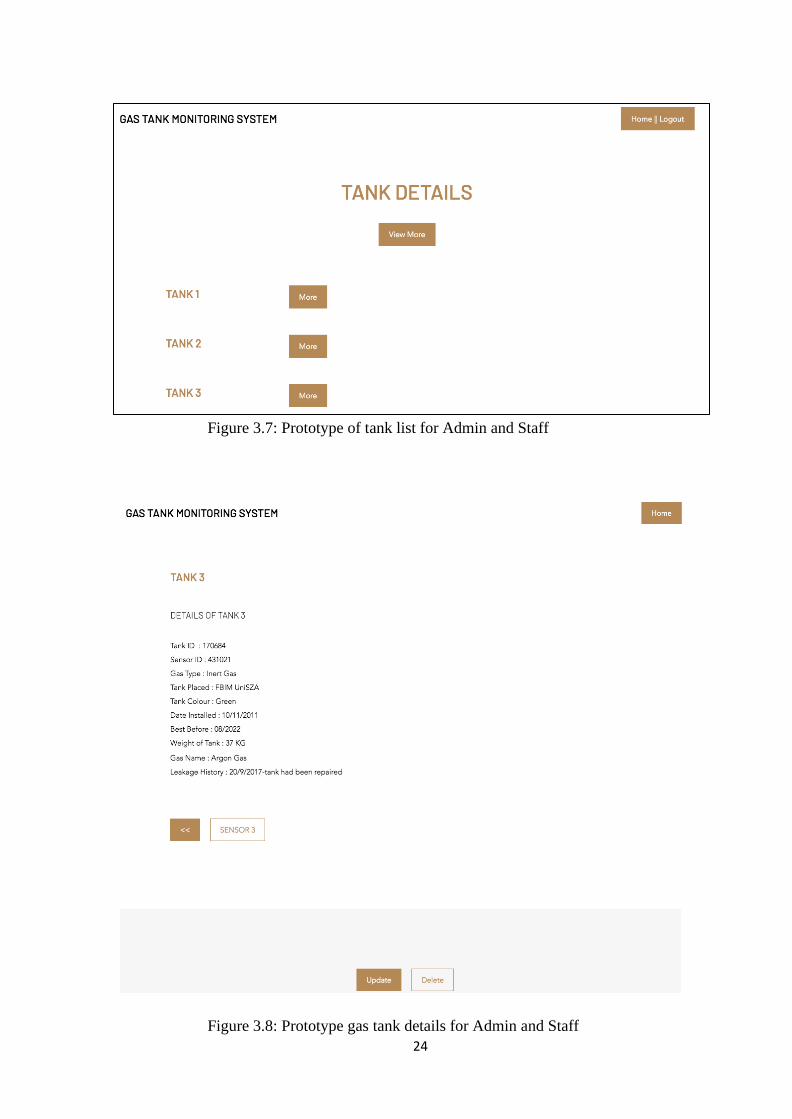
Figure 3.7: Prototype of tank list for Admin and Staff
Figure 3.8: Prototype gas tank details for Admin and Staff

25
Figure 3.9: Prototype of Sensor list page for Admin and Staff
Figure 3.10: Prototype of Sensor details for Admin and Staff

26
Figure 3.11: Prototype of UCL Staff list for Admin
Figure 3.12: Prototype of Staff profile for admin

27
Figure 3.13 Prototype of Leakage History List

28
Figure 3.14: Prototype of Alert Message on website
Figure 3.15: Prototype of Alert Message on mobile phone

29
3.12 Solution Complexity
3.12.1 Hybrid Technique
Hybrid mobile apps is the combine features of smartphone apps and
web apps. They are written in HTML5 and JavaScript, similar like web apps.
Mostly, they are web pages wrapped in a mobile app using WebView.
Nevertheless, they also have access to the built-in capabilities of a device.
Normally, they are built using cross-platform frameworks like React, Ionic,
Sencha and Xamarin. But for this project, I am using Laravel 5.7. Laravel is a
free, open-source PHP web framework and intended for the development of
web applications following the model–view–controller (MVC) architectural
pattern and based on Symfony. Therefore, HTML5 framework it needs a
native wrapper like Cordova in order to run as a native app.
Apache Cordova is a Hybrid application that uses standard web
technologies such as HTML5, CSS3, and JavaScript for cross-platform
complaint development. These applications execute inside wrappers targeted
platform. They access various device functions via standards-compliant API
bindings. We can extend a web application to be packaged and distribute it as a
mobile application on various platform using apache Cordova.

30
3.12.2 Algorithm
Figure 3.16: Algorithm of solution complexity of system
3.13 Summary
In this chapter, we describe the methodology that used by Gas Leakage
Detector and Monitoring System which is prototyping model. It also explains about
data model, process model, proof of concept, hardware and software requirement and
solution complexity that are used in this project that was guided to the success of this
project.

31
REFERENCES
[1] Gibson, G. M., Sun, B., Edgar, M. P., Phillips, D. B., Hempler, N., Maker, G. T., ... &
Padgett, M. J. (2017). Real-time imaging of methane gas leaks using a single-pixel
camera. Optics express, 25(4), 2998-3005.
[2] Jewel, M. U., DasGupta, B., & Valles, D. (2018). Gas and Air Quality Detection, and
Monitoring Using Embedded System for Nanofabrication Facility. In Proceedings of
the International Conference on Embedded Systems, Cyber-physical Systems, and
Applications (ESCS) (pp. 45-48). The Steering Committee of The World Congress in
Computer Science, Computer Engineering and Applied Computing (WorldComp).
[3] Mohd Iskandar, A. A. (N.D.)(2018).An LPG Leakage Detector System Using IoT) in
Profile View. Retrieved from https://eportfolio.utm.my/artefact/ artefact.php?
view=35008&artefact=375387
[4] Siddiqui, M. W., Mishra, H. M., & undefined, K. undefined. (2017). LPG Leakage
Detection and Prevention. (IJIR) Vol-3, Issue-5, ISSN: 2454-1362.
[5] Zhu, J., Ren, L., Ho, S. C., Jia, Z., & Song, G. (2017). Gas pipeline leakage
detection based on PZT sensors. Smart Materials and Structures, 26(2), 025022.
[6] Carrino A. (2016). Oxygen Monitors for Nitrogen, Argon, or Cryogenics.
[7] H. T., & A. P. (2017). Arduino Based Gas Leakage Detecting System. IJARIIE-
ISSN(O)-2395-4396.
[8] Anandhakrishnan, S., Nair, D., Rakesh, K., Sampath, K., & Nair, G. S. (2017). IOT
Based Smart Gas Monitoring System. In National Conference on" Emerging
Research Trends in Electrical, Electronics & Instrumentation (pp. 82-87).
[9] F. Chraim, Y. Erol & K. Pister (2016) Wireless gas leakage detection and
localization. IEEE Trans. Ind. Informat, vol.12, no. 2. 768-779
[10] Noor Muzamil Mohamad, Personal Communication, (October 8, 2019).
[11] Banchchan A., Bhasharkar K., Gundagi Z.M., Bhan V.(2016). Design of Smart LPG
Regulator using Internet of Things. ISSN 2349-4476, 4(2), 166–169. Research

32
Scholar, Dept. of Information Technology, Sinhgad Institute of Technology &
Science, Pune,India
[12] Dewi L, Somantri Y (2018). Wireless Sensor Network on LPG Gas Leak Detection
and Automatic Gas Regulator System Using Arduino. IOP Conf. Ser.: Mater. Sci.
Eng. 384 012064. Department of Electrical Engineering Education, Universitas
Pendidikan Indonesia, Bandung, Indonesia.
[13] Nasuhation H.T., Nasution R.Y., Nasution F.C. (2019). Automatic Regulator Design
for Liquified Petroleum Gas. IOP Conf. Ser.: Mater. Sci. Eng. 648 012012.
Department of Electrical Engineering, Universitas Sumatera Utara, Medan, Indonesia
[14] Lakshmi M.K.P., Sri Aruna P.S.G., Krishna G.P. (2019). An IOT Based LPG
Leakage Sensing and Alerting System. IJITEE-ISSN 2278-3075, 8(6).

33
APPENDIX
A) Gantt Chart (FYP 1)
Week/Activity 1 2 3 4 5 6 7 8 9 10 11 12 13 14 15 16
Final Year Project 1
Topic
Discussion
and
Determination
Project Title
Proposal
Introduction
Literature
Review
Proposal
Presentation
and Review
Discussion
and
Correction
Proposal
Methodology
Proof Of
Concept

34
Draft Report
Draft
Submission to
Supervisor
Seminar
Presentation
Report Correction
Final Report Submission

35
B) Gantt Chart (FYP 2)
Week/Activity 1 2 3 4 5 6 7 8 9 10 11 12 13 14 15 16
Final Year Project 2
Design
Interface
Implementation
And
Development
Presentation 1
Documentation
Integrated
added value
Testing
Seminar
Presentation
Draft Report
Draft
Submission to
Supervisor
Report
Correction
Final Report
Submission