gauff technical specifications - part 2€¦ · · 2012-09-191.1.3 reinforced concrete ... 2.6.5...
TRANSCRIPT
REPUBLIC OF SOUTH SUDAN MINISTRY OF WATER RESOURCES AND IRRIGATION YEI RIVER COUNTY
In Cooperation with
CONSULTANCY SERVICES FOR DETAILED DESIGN AND TENDER DOCUMENTATION FOR WATER AND SANITATION FACILITIES FOR YEI TOWN TECHNICAL SPECIFICATIONS
Chapter 2 Standard Specifications for Civil Works
MAY 2012
GAUFF INGENIEURE GmbH & Co. KG - JBG Berner Strasse 45
-60437 Frankfurt am Main, Germany
Email: [email protected]
Water and Sanitation Project, Yei, Southern Sudan May 2012 Consultancy – Design and Tender Documentation Standard Specifications for Civil Works
Gauff Ingenieure II
TECHNICAL SPECIFICATIONS
Chapter 2 Standard Specifications for Civil Works

Water and Sanitation Project, Yei, Southern Sudan May 2012 Consultancy – Design and Tender Documentation Standard Specifications for Civil Works
Gauff Ingenieure III
Table of Contents
1 GENERAL REQUIREMENTS .............................. ............................................................................. 1
1.1 GENERAL ................................................................................................................................... 1 1.1.1 Design nomenclature ....................................................................................................... 1 1.1.2 Design loads .................................................................................................................... 1 1.1.3 Reinforced concrete ......................................................................................................... 1 1.1.4 Timber works and scaffolding .......................................................................................... 1 1.1.5 Steelwork ......................................................................................................................... 2 1.1.6 Waterproofing .................................................................................................................. 2 1.1.7 Masonry work ................................................................................................................... 2 1.1.8 Codes of practice ............................................................................................................. 2
1.2 WORKS TO BE MEASURED ........................................................................................................... 2 1.3 APPROVAL OF MATERIALS AND WORKMANSHIP .............................................................................. 3
2 EARTHWORKS ........................................ ........................................................................................ 3
2.1 GENERAL ................................................................................................................................... 3 2.1.1 Scope ............................................................................................................................... 3 2.1.2 Definitions ........................................................................................................................ 3 2.1.3 Standards and rules ......................................................................................................... 3
2.2 GENERAL REQUIREMENTS ........................................................................................................... 4 2.2.1 Levels to be recorded ...................................................................................................... 4 2.2.2 Excess excavation to be made good ............................................................................... 4 2.2.3 Explosives ........................................................................................................................ 4 2.2.4 Temporary fencing and protection ................................................................................... 4 2.2.5 Safety measures .............................................................................................................. 4
2.3 PREPARATION OF SITE................................................................................................................. 4 2.3.1 Site clearance .................................................................................................................. 4 2.3.2 Trees and stumps ............................................................................................................ 4 2.3.3 Stripping topsoil ............................................................................................................... 5 2.3.4 Demolition works .............................................................................................................. 5
2.4 EXCAVATION ............................................................................................................................... 5 2.4.1 General excavation .......................................................................................................... 5 2.4.2 Maintaining and supporting other services and structures .............................................. 5 2.4.3 High Water Table to be Expected .................................................................................... 5 2.4.4 Excavation to be kept free from water ............................................................................. 6 2.4.5 Trial holes ........................................................................................................................ 6 2.4.6 Supporting excavations.................................................................................................... 6 2.4.7 Shoring ............................................................................................................................. 6 2.4.8 Disposition of excavated material .................................................................................... 7 2.4.9 Spoil tips on site ............................................................................................................... 7 2.4.10 Disposal of excavated material (off-site) .......................................................................... 7 2.4.11 Disposal of materials ........................................................................................................ 7 2.4.12 Trimming excavations and blinding ................................................................................. 7 2.4.13 Inspection by Engineer .................................................................................................... 7 2.4.14 Excavation beneath structures ........................................................................................ 8 2.4.15 Excavation beneath structure paved areas ..................................................................... 8 2.4.16 Over-excavation for structures ......................................................................................... 8 2.4.17 Trench excavation ............................................................................................................ 8 2.4.18 Trenches for inter-connections ........................................................................................ 8 2.4.19 Preparation of trench for inter-connections ..................................................................... 8 2.4.20 Trenches for transport lines ............................................................................................. 9 2.4.21 Excavation for transport lines .......................................................................................... 9 2.4.22 Preparation of trench for transport lines .......................................................................... 9 2.4.23 Trenches not to be left open ............................................................................................ 9
2.5 MATERIALS ................................................................................................................................. 9
Water and Sanitation Project, Yei, Southern Sudan May 2012 Consultancy – Design and Tender Documentation Standard Specifications for Civil Works
Gauff Ingenieure IV
2.5.1 Fill materials ..................................................................................................................... 9 2.5.2 Free draining fill / filters .................................................................................................. 10 2.5.3 Rip rap ........................................................................................................................... 10 2.5.4 Stone pitching ................................................................................................................ 10
2.6 BACKFILLING............................................................................................................................. 10 2.6.1 General .......................................................................................................................... 10 2.6.2 Filling adjacent to completed structures ........................................................................ 11 2.6.3 Refilling trenches ........................................................................................................... 11 2.6.4 Refill material - special measures .................................................................................. 12 2.6.5 Field drains .................................................................................................................... 12
2.7 EMBANKMENTS AND FILL ........................................................................................................... 12 2.7.1 Embankments generally ................................................................................................ 12 2.7.2 Materials for embankments ........................................................................................... 12 2.7.3 Filling with hardcore ....................................................................................................... 12
2.8 REINSTATEMENT ....................................................................................................................... 12 2.8.1 Surface reinstatement in field. ....................................................................................... 12 2.8.2 Surface reinstatement in roads ...................................................................................... 13 2.8.3 Existing services ............................................................................................................ 13 2.8.4 Hedges, fences and walls .............................................................................................. 13
2.9 TOPSOILING AND LANDSCAPING ................................................................................................. 13 2.9.1 General .......................................................................................................................... 13 2.9.2 Topsoiling ....................................................................................................................... 13 2.9.3 Landscaping and grassing ............................................................................................. 14
2.10 TESTING OF MATERIAL ............................................................................................................... 14 2.10.1 General .......................................................................................................................... 14 2.10.2 Main tests and standards ............................................................................................... 14 2.10.3 Compaction test ............................................................................................................. 14
2.11 GABIONS .................................................................................................................................. 15 2.12 AUXILIARY WORKS .................................................................................................................... 16
2.12.1 General .......................................................................................................................... 16 2.13 MEASUREMENT ......................................................................................................................... 16 2.14 SPECIAL MEASURES .................................................................................................................. 16
2.14.1 Refill material - PVC pipes ............................................................................................. 16
3 CONCRETE, REINFORCEMENT, FORMWORK AND JOINTS....... ............................................. 17
3.1 GENERAL ................................................................................................................................. 17 3.2 CONCRETE ............................................................................................................................... 17
3.2.1 Scope ............................................................................................................................. 17 3.2.2 Organisation of Concrete Production at the site ............................................................ 17 3.2.3 Test certificates .............................................................................................................. 17 3.2.4 Aggregate samples ........................................................................................................ 17 3.2.5 Record of concreting ...................................................................................................... 17 3.2.6 Concrete mixes .............................................................................................................. 18 3.2.7 Construction joints and lifts ............................................................................................ 18 3.2.8 Prestressed concrete ..................................................................................................... 18 3.2.9 Cement .......................................................................................................................... 18 3.2.10 Storage of cement .......................................................................................................... 18 3.2.11 Aggregates ..................................................................................................................... 19 3.2.12 Storage of aggregates ................................................................................................... 19 3.2.13 Water.............................................................................................................................. 19 3.2.14 Admixtures ..................................................................................................................... 19 3.2.15 Calcium chloride ............................................................................................................ 20 3.2.16 Test equipment .............................................................................................................. 20 3.2.17 Proportioning in general ................................................................................................. 20 3.2.18 Water-cement ratio and compressive strength .............................................................. 20 3.2.19 Limits of salt content ...................................................................................................... 20 3.2.20 Consistency ................................................................................................................... 21 3.2.21 Mix design ...................................................................................................................... 21
Water and Sanitation Project, Yei, Southern Sudan May 2012 Consultancy – Design and Tender Documentation Standard Specifications for Civil Works
Gauff Ingenieure V
3.2.22 Trial mixes ...................................................................................................................... 21 3.2.23 Material batching ............................................................................................................ 22 3.2.24 Mixing Concrete ............................................................................................................. 22 3.2.25 Ready-mixed concrete ................................................................................................... 23 3.2.26 Preparing for concreting................................................................................................. 23 3.2.27 Exclusion of water .......................................................................................................... 23 3.2.28 Transporting and placing ............................................................................................... 24 3.2.29 Concreting in hot weather .............................................................................................. 25 3.2.30 Compaction .................................................................................................................... 25 3.2.31 Attendance of steel fixer and carpenter ......................................................................... 26 3.2.32 Curing of concrete .......................................................................................................... 26 3.2.33 Care and repair of concrete ........................................................................................... 26 3.2.34 Finish of concrete surfaces ............................................................................................ 27 3.2.35 Unformed surfaces ......................................................................................................... 27 3.2.36 Treatment of surface defects ......................................................................................... 27 3.2.37 Building-in pipes and plant ............................................................................................. 28 3.2.38 Puddle flanges and pipe supports ................................................................................. 28 3.2.39 Corrosion protection requirements ................................................................................ 28 3.2.40 Precast concrete ............................................................................................................ 28 3.2.41 Installation of precast concrete units ............................................................................. 29 3.2.42 Prestressed concrete ..................................................................................................... 29 3.2.43 No-fines concrete ........................................................................................................... 29 3.2.44 Precast concrete products ............................................................................................. 30 3.2.45 Concrete for benching.................................................................................................... 30 3.2.46 Air-entrained concrete.................................................................................................... 30 3.2.47 Pumping concrete .......................................................................................................... 30 3.2.48 Sampling and testing of aggregate ................................................................................ 30 3.2.49 Sampling and testing of concrete .................................................................................. 30 3.2.50 Compliance with specified requirements ....................................................................... 31 3.2.51 Non-compliance ............................................................................................................. 31 3.2.52 Cutting and testing of core samples .............................................................................. 31 3.2.53 Inspection procedures.................................................................................................... 32 3.2.54 Concrete protection system ........................................................................................... 32 3.2.55 Concrete protection procedures .................................................................................... 34 3.2.56 Machinery bases and grouting in ................................................................................... 34 3.2.57 Test for watertightness of water-retaining structures ..................................................... 34
3.3 REINFORCEMENT ...................................................................................................................... 34 3.3.1 Scope ............................................................................................................................. 34 3.3.2 Submissions ................................................................................................................... 34 3.3.3 Steel reinforcement ........................................................................................................ 35 3.3.4 Steel wire and bars for prestressing .............................................................................. 35 3.3.5 Accessories .................................................................................................................... 35 3.3.6 Dowels ........................................................................................................................... 35 3.3.7 Detailing ......................................................................................................................... 35 3.3.8 Cutting and bending of reinforcement............................................................................ 35 3.3.9 Storage of reinforcing bars and fabric ............................................................................ 35 3.3.10 Storage of prestressing wire and bars ........................................................................... 36 3.3.11 Fixing of reinforcement .................................................................................................. 36 3.3.12 Concrete cover ............................................................................................................... 36 3.3.13 Tolerances ..................................................................................................................... 36 3.3.14 Inspection and testing .................................................................................................... 36 3.3.15 Straightening .................................................................................................................. 36 3.3.16 Approval by Engineer..................................................................................................... 36
3.4 FORMWORK .............................................................................................................................. 37 3.4.1 Scope ............................................................................................................................. 37 3.4.2 Submissions ................................................................................................................... 37 3.4.3 General .......................................................................................................................... 37 3.4.4 Form ties ........................................................................................................................ 37

Water and Sanitation Project, Yei, Southern Sudan May 2012 Consultancy – Design and Tender Documentation Standard Specifications for Civil Works
Gauff Ingenieure VI
3.4.5 Number of forms ............................................................................................................ 37 3.4.6 Design ............................................................................................................................ 37 3.4.7 Vertical surfaces ............................................................................................................ 38 3.4.8 Formed surfaces - class of finish ................................................................................... 38 3.4.9 Erection of formwork ...................................................................................................... 38 3.4.10 Maintenance of forms .................................................................................................... 39 3.4.11 Removal of formwork ..................................................................................................... 39 3.4.12 Building in plant .............................................................................................................. 39 3.4.13 Inspection and testing .................................................................................................... 39
3.5 JOINTS ..................................................................................................................................... 39 3.5.1 Construction joints ......................................................................................................... 39 3.5.2 Performance of construction joints and lifts ................................................................... 40 3.5.3 Movement joints generally ............................................................................................. 41 3.5.4 Sliding planes ................................................................................................................. 42
4 MASONRY AND PLASTER WORK .......................... ..................................................................... 42
4.1 SCOPE ..................................................................................................................................... 42 4.2 MASONRY WORK ....................................................................................................................... 42
4.2.1 Materials ........................................................................................................................ 42 4.2.2 Workmanship ................................................................................................................. 43
4.3 RENDERING AND PLASTERING .................................................................................................... 45 4.3.1 General .......................................................................................................................... 45 4.3.2 Materials ........................................................................................................................ 45 4.3.3 Mixing ............................................................................................................................. 46 4.3.4 Preparation .................................................................................................................... 46 4.3.5 Finish.............................................................................................................................. 46 4.3.6 Tolerances ..................................................................................................................... 46 4.3.7 Connection of work ........................................................................................................ 46 4.3.8 Thickness and workmanship ......................................................................................... 46 4.3.9 Waterproof ..................................................................................................................... 47 4.3.10 Measurement for payment ............................................................................................. 47
5 TILING, FLOORING, SCREEDS, SUSPENDED CEILINGS AND R OOFING............................... 47
5.1 SCOPE ..................................................................................................................................... 47 5.2 TILING ...................................................................................................................................... 47
5.2.1 General .......................................................................................................................... 47 5.2.2 Materials ........................................................................................................................ 48 5.2.3 Tiles - adhesives ............................................................................................................ 48 5.2.4 General preparation ....................................................................................................... 48 5.2.5 Preparation of tiles ......................................................................................................... 48 5.2.6 Placing ........................................................................................................................... 49 5.2.7 Bedding .......................................................................................................................... 49 5.2.8 Jointing ........................................................................................................................... 49 5.2.9 Tolerances ..................................................................................................................... 50 5.2.10 Stone, concrete and marble slabs ................................................................................. 50 5.2.11 Measurement for payment ............................................................................................. 51
5.3 FLOORING ................................................................................................................................ 51 5.3.1 General .......................................................................................................................... 51 5.3.2 Materials ........................................................................................................................ 51 5.3.3 Workmanship generally ................................................................................................. 51 5.3.4 Preparation of the surface ............................................................................................. 52 5.3.5 General requirements for application ............................................................................. 52 5.3.6 Marble ............................................................................................................................ 52 5.3.7 Precast concrete slabs................................................................................................... 53 5.3.8 Thin floor coverings: PVC .............................................................................................. 53 5.3.9 Fitting of cover strips and nosings ................................................................................. 53
5.4 SCREEDS ................................................................................................................................. 53 5.4.1 General .......................................................................................................................... 53

Water and Sanitation Project, Yei, Southern Sudan May 2012 Consultancy – Design and Tender Documentation Standard Specifications for Civil Works
Gauff Ingenieure VII
5.4.2 Floor screeds and in-situ finishings ............................................................................... 53 5.4.3 Weather conditions ........................................................................................................ 53 5.4.4 Screed dimensions ........................................................................................................ 53 5.4.5 Materials ........................................................................................................................ 53 5.4.6 Base concrete preparation ............................................................................................. 54 5.4.7 Screed mix ..................................................................................................................... 54 5.4.8 Placing and compaction ................................................................................................. 54 5.4.9 Finishing ......................................................................................................................... 54 5.4.10 Curing and protection..................................................................................................... 54 5.4.11 Tolerances ..................................................................................................................... 55 5.4.12 In-situ toppings ............................................................................................................... 55 5.4.13 Measurement for payment ............................................................................................. 55
5.5 SUSPENDED CEILINGS ............................................................................................................... 56 5.5.1 General .......................................................................................................................... 56 5.5.2 Materials ........................................................................................................................ 56 5.5.3 General requirements .................................................................................................... 56 5.5.4 Coordination ................................................................................................................... 56 5.5.5 Suspension systems ...................................................................................................... 57 5.5.6 Setting out tiles .............................................................................................................. 57 5.5.7 Fixing devices ................................................................................................................ 57 5.5.8 Measurement for Payment ............................................................................................ 57
5.6 ROOFING .................................................................................................................................. 57 5.6.1 General .......................................................................................................................... 57 5.6.2 Waterproofing ................................................................................................................ 57 5.6.3 Roof insulation ............................................................................................................... 57 5.6.4 Precast cement and sand roofing tiles ........................................................................... 57 5.6.5 Aluminium flashing ......................................................................................................... 57 5.6.6 Screeds .......................................................................................................................... 58 5.6.7 Rainwater outlets ........................................................................................................... 58 5.6.8 Workmanship ................................................................................................................. 58 5.6.9 Galvanized iron sheet covering (Pitched roofs) ............................................................. 58 5.6.10 Timber roof structures (pitched roofs) ............................................................................ 58
6 TIMBER AND GLAZING................................. ................................................................................ 59
6.1 SCOPE ..................................................................................................................................... 59 6.2 TIMBER .................................................................................................................................... 59
6.2.1 General .......................................................................................................................... 59 6.2.2 Materials ........................................................................................................................ 59 6.2.3 Soft wood ....................................................................................................................... 59 6.2.4 Hardwood ....................................................................................................................... 59 6.2.5 Plywood ......................................................................................................................... 59 6.2.6 Fibreboard ...................................................................................................................... 59 6.2.7 Hardboard ...................................................................................................................... 59 6.2.8 Chipboard ...................................................................................................................... 59 6.2.9 Melamine ....................................................................................................................... 60 6.2.10 Samples ......................................................................................................................... 60 6.2.11 Miscellaneous material .................................................................................................. 60 6.2.12 Ironmongery ................................................................................................................... 60 6.2.13 Selected timber .............................................................................................................. 60 6.2.14 Protection of soft wood .................................................................................................. 60 6.2.15 Moisture content of timber ............................................................................................. 61 6.2.16 Wet-check meter ............................................................................................................ 61 6.2.17 Dimensions .................................................................................................................... 61 6.2.18 Exposed faces ............................................................................................................... 61 6.2.19 Natural finish .................................................................................................................. 61 6.2.20 Shrinkage ....................................................................................................................... 61 6.2.21 Tolerance ....................................................................................................................... 61 6.2.22 Fabrication ..................................................................................................................... 61
Water and Sanitation Project, Yei, Southern Sudan May 2012 Consultancy – Design and Tender Documentation Standard Specifications for Civil Works
Gauff Ingenieure VIII
6.2.23 Joints .............................................................................................................................. 62 6.2.24 Adhesives ...................................................................................................................... 62 6.2.25 Mouldings ....................................................................................................................... 62 6.2.26 Bendwork ....................................................................................................................... 62 6.2.27 Circular work .................................................................................................................. 62 6.2.28 Veneering ....................................................................................................................... 62 6.2.29 Scribing .......................................................................................................................... 62 6.2.30 Capillarity ....................................................................................................................... 62 6.2.31 Weathering ..................................................................................................................... 62 6.2.32 Finishing ......................................................................................................................... 62 6.2.33 Hardwood work fixings ................................................................................................... 63 6.2.34 Priming ........................................................................................................................... 63 6.2.35 Accuracy ........................................................................................................................ 63 6.2.36 Defective work ............................................................................................................... 63 6.2.37 Clearing up ..................................................................................................................... 63 6.2.38 Framing .......................................................................................................................... 63 6.2.39 Fixing of frames ............................................................................................................. 63 6.2.40 Flush doors .................................................................................................................... 63 6.2.41 Hardwood doors ............................................................................................................. 63 6.2.42 Hardboard in doors ........................................................................................................ 64 6.2.43 Folding shutter doors ..................................................................................................... 64 6.2.44 Frames ........................................................................................................................... 64 6.2.45 Floor runners .................................................................................................................. 64 6.2.46 Timber ceilings ............................................................................................................... 64 6.2.47 Timber boarded floors .................................................................................................... 64 6.2.48 Timber soffits ................................................................................................................. 64
6.3 GLASS AND GLAZING ................................................................................................................. 64 6.3.1 General .......................................................................................................................... 64 6.3.2 Materials ........................................................................................................................ 64 6.3.3 Size delivery and storage .............................................................................................. 65 6.3.4 Installation ...................................................................................................................... 65 6.3.5 Tests .............................................................................................................................. 65 6.3.6 Cleaning Up ................................................................................................................... 65
7 MISCELLANEOUS BUILDING WORKS ...................... .................................................................. 66
7.1 SCOPE ..................................................................................................................................... 66 7.2 SUNDRY ITEMS ......................................................................................................................... 66
7.2.1 Drying and cleaning ....................................................................................................... 66 7.2.2 Fixing to structures. brick and concrete etc. .................................................................. 66 7.2.3 Metal windows, louvres and doors ................................................................................. 66 7.2.4 Kind of windows and doors ............................................................................................ 66
7.3 FINISH HARDWARE .................................................................................................................... 67 7.3.1 General .......................................................................................................................... 67 7.3.2 Hardware description ..................................................................................................... 67
7.4 SANITARY INSTALLATION ........................................................................................................... 68 7.4.1 Connections to equipment and fixtures ......................................................................... 68 7.4.2 Cutting and repairing...................................................................................................... 68 7.4.3 Protection to fixtures and equipment ............................................................................. 68 7.4.4 Sanitary. waste water and vent piping - generally ......................................................... 68 7.4.5 Sanitary, waste water and vent piping installations ....................................................... 68 7.4.6 Buried drainage pipes .................................................................................................... 68 7.4.7 Flashing ......................................................................................................................... 69 7.4.8 Traps .............................................................................................................................. 69 7.4.9 Floor drains .................................................................................................................... 69 7.4.10 Downspouts and gutters ................................................................................................ 69 7.4.11 Water pipe, fittings and connection - generally .............................................................. 69 7.4.12 Water pipe, fittings and connection ................................................................................ 69 7.4.13 Valves ............................................................................................................................ 70
Water and Sanitation Project, Yei, Southern Sudan May 2012 Consultancy – Design and Tender Documentation Standard Specifications for Civil Works
Gauff Ingenieure IX
7.4.14 Unions ............................................................................................................................ 70 7.4.15 Hose taps ....................................................................................................................... 70 7.4.16 Pipe sleeves ................................................................................................................... 70 7.4.17 Pipe hangers insert and supports .................................................................................. 70 7.4.18 Fixture support ............................................................................................................... 70 7.4.19 Type of fixtures - generally ............................................................................................ 71 7.4.20 Fixtures .......................................................................................................................... 71 7.4.21 Testing and sterilization of sanitary system - generally ................................................. 72 7.4.22 Drainage and venting system ........................................................................................ 72 7.4.23 Water test for drainage and venting system .................................................................. 72 7.4.24 Final test ........................................................................................................................ 72 7.4.25 Testing and sterilization of water system ....................................................................... 72 7.4.26 Cleaning and adjusting .................................................................................................. 73 7.4.27 Disinfection .................................................................................................................... 73
7.5 FIRE PROTECTION..................................................................................................................... 73 7.6 DISINFECTION ........................................................................................................................... 73
7.6.1 General .......................................................................................................................... 73 7.6.2 Preliminary cleansing and flushing ................................................................................ 74 7.6.3 Disinfection .................................................................................................................... 74
8 ENGINEERING METALWORK ............................. ......................................................................... 75
8.1 SCOPE ..................................................................................................................................... 75 8.1.1 General .......................................................................................................................... 75 8.1.2 Design and detailing ...................................................................................................... 75 8.1.3 Erection .......................................................................................................................... 75
8.2 WELDING AND HEAT TREATMENT ................................................................................................ 75 8.2.1 General .......................................................................................................................... 75 8.2.2 Preparation for welding .................................................................................................. 75
8.3 FLOORING ................................................................................................................................ 75 8.3.1 General .......................................................................................................................... 75 8.3.2 Floor plating ................................................................................................................... 76 8.3.3 Cast iron access covers ................................................................................................. 76 8.3.4 Permissible differences .................................................................................................. 76 8.3.5 Handrailing ..................................................................................................................... 76
8.4 LADDERING AND STAIRWAYS ...................................................................................................... 77 8.4.1 General .......................................................................................................................... 77 8.4.2 Ladders .......................................................................................................................... 77 8.4.3 Steel stairways ............................................................................................................... 77
8.5 MISCELLANEOUS ....................................................................................................................... 78 8.5.1 Dissimilar metals ............................................................................................................ 78 8.5.2 Opening tools ................................................................................................................. 78 8.5.3 Step irons ....................................................................................................................... 78 8.5.4 Surface boxes ................................................................................................................ 78 8.5.5 Road gully gratings ........................................................................................................ 78 8.5.6 Protection ....................................................................................................................... 78 8.5.7 Installation ...................................................................................................................... 78 8.5.8 Inspection and testing .................................................................................................... 79
9 PAINTING AND PROTECTIVE COATING.................... ................................................................. 80
9.1 GENERAL ................................................................................................................................. 80 9.2 CONTRACTOR'S RESPONSIBILITY ................................................................................................ 80 9.3 SUBMISSIONS ........................................................................................................................... 80 9.4 APPROPRIATE STANDARDS ........................................................................................................ 81 9.5 LOCAL CONDITIONS ................................................................................................................... 81 9.6 DECORATIVE FINISH AND FINAL APPEARANCE .............................................................................. 81 9.7 COATINGS IN CONTACT WITH PORTABLE WATER .......................................................................... 81 9.8 TRIAL AREAS AND SAMPLE PIECES .............................................................................................. 81 9.9 PRECAUTIONS, ETC. .................................................................................................................. 82

Water and Sanitation Project, Yei, Southern Sudan May 2012 Consultancy – Design and Tender Documentation Standard Specifications for Civil Works
Gauff Ingenieure X
9.10 WORK SUCCESSION .................................................................................................................. 82 9.11 APPLICATION OF PROTECTIVE COATING AND PAINT SYSTEM ......................................................... 82 9.12 EQUIPMENT AND CONDITION ...................................................................................................... 82 9.13 PAINT THICKNESS AND CONTINUITY ............................................................................................ 82 9.14 DRY FILM THICKNESS ................................................................................................................ 83 9.15 COLOUR CODING ....................................................................................................................... 83 9.16 KNOTTING AND STOPPING .......................................................................................................... 84 9.17 PAINT SOURCE AND SUPERVISION .............................................................................................. 84 9.18 SYSTEM TO BE COMPATIBLE AND COMPLETE ............................................................................... 84 9.19 BITUMEN COATING .................................................................................................................... 84 9.20 IDENTIFICATION ......................................................................................................................... 84 9.21 STORAGE AND USE OF PAINT, THINNERS ETC. ............................................................................. 84 9.22 PAINT PREPARATION ................................................................................................................. 85 9.23 WASTE ..................................................................................................................................... 85 9.24 SPRAY APPLICATION .................................................................................................................. 85 9.25 BRUSH APPLICATION ................................................................................................................. 85 9.26 METAL COATINGS ...................................................................................................................... 85 9.27 PREFABRICATION PRIMERS ........................................................................................................ 85 9.28 SURFACE PREPARATION BY BLASTING ........................................................................................ 85 9.29 DEHUMIDIFICATION REQUIRED FOR SPECIAL PURPOSES............................................................... 85 9.30 CLASSIFICATION OF PAINTING .................................................................................................... 86 9.31 EMBEDDED STEEL ..................................................................................................................... 86 9.32 UNCOATED SURFACES .............................................................................................................. 86 9.33 REPAIR OF DAMAGED WORK - GENERAL ...................................................................................... 86 9.34 FASTENINGS ............................................................................................................................. 86 9.35 PAINTING AND PROTECTION OF BOLTED CONNECTIONS................................................................ 87 9.36 COPPER AND BRASS .................................................................................................................. 87 9.37 PLASTER AND CONCRETE PROTECTION ...................................................................................... 87 9.38 PREPARATION OF CONCRETE AND RENDERED SURFACES ............................................................ 87 9.39 MINIMUM THICKNESS AND ADHESION TESTS FOR PAINTING SYSTEMS FOR CONCRETE AND PLASTER 87 9.40 PREPARATION OF PLASTER, BRICKWORK AND CONCRETE SURFACES ........................................... 87 9.41 PREPARATION OF WOOD SURFACES ........................................................................................... 88 9.42 FINAL TREATMENT OF WOOD, PLASTER, ETC ............................................................................... 88
10 PIPELINES ................................................................................................................................. 88
10.1 SCOPE ..................................................................................................................................... 88 10.2 GENERAL ................................................................................................................................. 88 10.3 MATERIALS ............................................................................................................................... 88
10.3.1 Ductile iron pipes and fittings ......................................................................................... 88 10.3.2 Steel pipes and fittings ................................................................................................... 88 10.3.3 Asbestos cement pipes and fittings ............................................................................... 88 10.3.4 Polyvinyl -chloride pipes ................................................................................................ 89 10.3.5 Repair of coating and linings ......................................................................................... 89 10.3.6 Joints - general requirements ........................................................................................ 89 10.3.7 Push-on joints ................................................................................................................ 89 10.3.8 Mechanical joints ........................................................................................................... 89 10.3.9 Flanged joints ................................................................................................................. 89 10.3.10 Welded joints ............................................................................................................. 89 10.3.11 Screwed joints ........................................................................................................... 89 10.3.12 Thrust resisting .......................................................................................................... 90
10.4 HANDLING AND STORAGE .......................................................................................................... 90 10.4.1 General .......................................................................................................................... 90 10.4.2 Ductile iron pipes ........................................................................................................... 90 10.4.3 Steel pipes ..................................................................................................................... 90 10.4.4 Asbestos cement pipes .................................................................................................. 90 10.4.5 Polyvinyl-chloride pipes ................................................................................................. 90 10.4.6 Stacking pipes ................................................................................................................ 91 10.4.7 Taking delivery of pipes and valves provided by Contractor ......................................... 91
Water and Sanitation Project, Yei, Southern Sudan May 2012 Consultancy – Design and Tender Documentation Standard Specifications for Civil Works
Gauff Ingenieure XI
10.4.8 Transport on site ............................................................................................................ 91 10.4.9 Temporary storage ......................................................................................................... 91 10.4.10 Inspection at time of installation ................................................................................ 91
10.5 CUTTING OF PIPES .................................................................................................................... 92 10.5.1 Ductile iron pipe ............................................................................................................. 92 10.5.2 Steel pipe ....................................................................................................................... 92 10.5.3 Asbestos cement pipe.................................................................................................... 92 10.5.4 Polyvinyl -chloride pipe .................................................................................................. 92 10.5.5 Closing lengths .............................................................................................................. 92
10.6 INSTALLATION OF PIPES - GENERALLY ......................................................................................... 92 10.7 INSTALLATION OF PIPES UNDERGROUND ..................................................................................... 92
10.7.1 Lowering of pipes into trench ......................................................................................... 92 10.7.2 Cleaning of pipes and fittings ......................................................................................... 93 10.7.3 Laying of pipes ............................................................................................................... 93 10.7.4 Coordination with excavation ......................................................................................... 93 10.7.5 Socket ends ................................................................................................................... 93 10.7.6 Unsuitable conditions ..................................................................................................... 93 10.7.7 Pipe insulation ................................................................................................................ 93 10.7.8 Buried ductile iron pipes................................................................................................. 93 10.7.9 Bedding to pipes ............................................................................................................ 94 10.7.10 Concrete bed and surround ....................................................................................... 94 10.7.11 Installation of pipes above around ............................................................................. 94 10.7.12 Installation of service connections ............................................................................. 94
10.8 INSTALLATION OF VALVES AND FITTINGS ..................................................................................... 94 10.8.1 General .......................................................................................................................... 94 10.8.2 Air valves ....................................................................................................................... 94 10.8.3 Washouts ....................................................................................................................... 95 10.8.4 Fire hydrants .................................................................................................................. 95 10.8.5 Isolation valves .............................................................................................................. 95 10.8.6 Bends and fittings .......................................................................................................... 95 10.8.7 Blind ends ...................................................................................................................... 95 10.8.8 Valve chambers and similar structures .......................................................................... 95 10.8.9 Anchor blocks ................................................................................................................ 95 10.8.10 Concrete protection ................................................................................................... 96 10.8.11 Railway crossings ...................................................................................................... 96 10.8.12 Metal tape .................................................................................................................. 96
10.9 TESTING, DISINFECTION AND RINSING ......................................................................................... 96 10.9.1 General .......................................................................................................................... 96 10.9.2 Testing ........................................................................................................................... 96 10.9.3 Cleaning out after testing ............................................................................................... 96 10.9.4 Disinfection .................................................................................................................... 97 10.9.5 Water for testing and cleaning ....................................................................................... 97
10.10 MARKERS ............................................................................................................................. 97
11 SITEWORKS .............................................................................................................................. 97
11.1 SCOPE ..................................................................................................................................... 97 11.2 MASS EARTHWORKS ................................................................................................................. 97 11.3 ROADS, PAVEMENTS AND SURFACE DRAINAGE ........................................................................... 97
11.3.1 Design of roads .............................................................................................................. 97 11.3.2 Design of drainage ......................................................................................................... 97 11.3.3 Precast concrete kerbs and flags .................................................................................. 97 11.3.4 Pipes and fittings ............................................................................................................ 98 11.3.5 Manholes chambers and gullies .................................................................................... 98
11.4 ROADS AND PAVEMENTS ........................................................................................................... 98 11.4.1 General .......................................................................................................................... 98 11.4.2 Formation and subgrade ................................................................................................ 98 11.4.3 Sub-base and roadbase ................................................................................................ 99 11.4.4 Sealing ........................................................................................................................... 99

Water and Sanitation Project, Yei, Southern Sudan May 2012 Consultancy – Design and Tender Documentation Standard Specifications for Civil Works
Gauff Ingenieure XII
11.4.5 Surface dressing ............................................................................................................ 99 11.4.6 Flexible road surfacing ................................................................................................... 99 11.4.7 Delivery of coated macadam ......................................................................................... 99 11.4.8 Concrete paved areas.................................................................................................. 100 11.4.9 Kerbs ............................................................................................................................ 100 11.4.10 Gravel roads ............................................................................................................ 100 11.4.11 Footpaths ................................................................................................................. 101 11.4.12 Reinstatement of existing roads and footpaths ....................................................... 101
11.5 SURFACE DRAINAGE ................................................................................................................ 101 11.5.1 General ........................................................................................................................ 101 11.5.2 Drainage work .............................................................................................................. 101
11.6 FENCING AND GATES ............................................................................................................... 101 11.6.1 General ........................................................................................................................ 101 11.6.2 Standard fencing .......................................................................................................... 102 11.6.3 Security fencing ........................................................................................................... 102 11.6.4 Gates............................................................................................................................ 102 11.6.5 Installation .................................................................................................................... 102
11.7 TESTS AND INSPECTION - GENERALLY ...................................................................................... 103 11.8 CONCRETE REPAIR AND REFURBISHMENT ................................................................................ 103
11.8.1 Scope ........................................................................................................................... 103 11.8.2 Personnel ..................................................................................................................... 103 11.8.3 Equipment .................................................................................................................... 103 11.8.4 Clearing of rubbish etc. and cleaning of structures ..................................................... 103 11.8.5 Delivery and storage of materials ................................................................................ 104 11.8.6 Preparation of subbase ................................................................................................ 104 11.8.7 Survey, investigations and reporting ............................................................................ 104 11.8.8 Works not specified ...................................................................................................... 104 11.8.9 Dust exhaust ................................................................................................................ 104 11.8.10 Provisions for protection .......................................................................................... 104 11.8.11 Waste ....................................................................................................................... 105 11.8.12 Drainage .................................................................................................................. 105 11.8.13 Protective coating system........................................................................................ 105 11.8.14 Crack injection, general ........................................................................................... 105 11.8.15 Preparation of subbase for injection ........................................................................ 106 11.8.16 Installation of nuts and packers, tamping ................................................................ 106 11.8.17 Injection ................................................................................................................... 106 11.8.18 Replacement of and/or additional reinforcement..................................................... 106 11.8.19 Daily reports ............................................................................................................ 106 11.8.20 Tests ........................................................................................................................ 107 11.8.21 Cover meters ........................................................................................................... 107 11.8.22 Measurement and payment ..................................................................................... 107
12 ANNEX...................................................................................................................................... 109

Water and Sanitation Project, Yei, Southern Sudan May 2012 Consultancy – Design and Tender Documentation Standard Specifications for Civil Works
Gauff Ingenieure 1
PART 6.2 STANDARD SPECIFICATION FOR CIVIL WORKS
1 GENERAL REQUIREMENTS
1.1 GENERAL
This Specification sets out, but is not limited to, the main DIN standards to be used by Contractor for the design, construction, supply and erection of the works.
1.1.1 Design nomenclature DIN 1080 Definitions, formula-signs and technical units for civil works
DIN 1356 Drawings for civil works
1.1.2 Design loads DIN 1055 Design loads for civil works (general), characteristic values of soil, traffic loads,
wind load
DIN 1072 Design loads for bridges
DIN 4112 Design loads for mobile structures subsoil and foundation
DIN 1054 Subsoil; design loads
DIN 4014 Piling
DIN 4017 Calculations for foundation failure
DIN 4018 Calculation of soil pressure below spread foundation
DIN 4019 Calculation of settlements
DIN 4021 Exploration of subsoil
DIN 4026 Driving piles
DIN 4084 Calculations of Slope failure
DIN 4095 Subsoil; drainage
DIN 4124 Subsoil and trenches; slopes, working spaces, supporting
DIN 4085 Subsoil; calculation of earth pressure at retaining walls
1.1.3 Reinforced concrete DIN 1045 Concrete and reinforced concrete, dimensioning and performance
DIN 1048 Quality tests of concrete
DIN 1164 Cement
DIN 4226 Concrete aggregates; definitions, sizes, quality requirements and testing
DIN 488 Reinforcing steel; dimensions, quality requirements, marking and testing
DIN 4099 Welding of Reinforcing steel
DIN 1084 Quality control for concrete
1.1.4 Timber works and scaffolding DIN 1052 Timber works; performance
DIN 68800 Protective coating for woodwork
DIN 4074 Construction timber; quality requirements
DIN 4420 Scaffolding; calculations and performance

Water and Sanitation Project, Yei, Southern Sudan May 2012 Consultancy – Design and Tender Documentation Standard Specifications for Civil Works
Gauff Ingenieure 2
1.1.5 Steelwork DIN 4114 Steelwork; basis for calculation, instructions, terms of reference
DIN 15018 Steel construction; basis for design and performance, calculations
DIN 18800 Steel construction; dimensioning, construction, welding
DIN 4102 Fire capability of structural elements
DIN 18230 Fire resistance of structural elements
1.1.6 Waterproofing DIN 18795 Waterproofing for structures; general, materials, dimensioning and performance
1.1.7 Masonry work DIN 1053 Masonry work; calculations and performance
1.1.8 Codes of practice DIN 18300 Earthworks
DIN 18301 Drilling works
DIN 18303 Excavation lining
DIN 18304 Driving works
DIN 18305 Ground water lowering
DIN 18330 Masonry works
DIN 18331 Concrete and reinforced concrete
DIN 18332 Natural stonework
DIN 18333 Artificial stonework
DIN 18334 Carpentry
DIN 18336 Waterproofing against moisture
DIN 18337 Waterproofing against pressurized
DIN 18338 Roofing
DIN 18339 Plumbing works
DIN 18350 Plastering
DIN 18352 Tiling
DIN 18353 Screeding works
DIN 18354 Bituminous paving
DIN 18355 Joinery
DIN 18361 Glazing
DIN 18363 Painting works
DIN 18365 Flooring
DIN 18379 Ventilation works
DIN 18381 Sanitary installation
1.2 WORKS TO BE MEASURED
In the case of lump sum, the Contractor shall estimate the percentage of completion for all work he intends to claim for his payment certificates. The Contractor’s estimate is subject to the Engineer’s
Water and Sanitation Project, Yei, Southern Sudan May 2012 Consultancy – Design and Tender Documentation Standard Specifications for Civil Works
Gauff Ingenieure 3
approval.
Wherever levels, measurements, quantities, etc. of any work done cannot be checked at a later stage, the measurements made by the Engineer or approved by him, shall be taken to be correct measurements of the work.
The contractor shall provide all survey instruments and measuring equipment required. The cost for the measurement of works shall be deemed to be included in the respective unit prices for construction and installation of works.
1.3 APPROVAL OF MATERIALS AND WORKMANSHIP
The supply of all materials, items and accessories shall be subject to the approval of the Engineer. The Contractor shall provide such samples as the Engineer may require in advance for the purposes of approval and when approved the quality shall be at least equal to the approved samples.
The Contractor shall furthermore provide sample areas, panels, or items of finished workmanship for approval by the Engineer as required by the Engineer. All workmanship shall be at least equal to the approved samples.
2 EARTHWORKS
2.1 GENERAL
2.1.1 Scope This Specification covers the requirements for site clearance, demolition, excavation, shoring, backfilling, compaction, importation or exportation of materials, placing and compacting fill for embankments and other related earthworks required for structural works and installation of pipelines and appurtenances as specified. The work shall also include the placing of rip rap or stone pitching for bank protection.
2.1.2 Definitions The following terms shall have the meanings assigned to them:
“topsoil” means any surface material, including turf, suitable for use in soiling areas to be grassed or cultivated (class 1, DIN 18300).
“rock” is defined as material occurring in solid unweathered banks or layers which, in the opinion of the Engineer, can only be removed by blasting, percussion drilling, wedging or splitting. Boulders exceeding one cubic metre in volume shall be classified as “rock” (class 7, DIN 18300).
“Subsoil” any material other than topsoil and rock shall be classified as (class 2-6, DIN 18300).
means excavation in open cut (excluding trench excavation) down to levels specified on the drawings or otherwise as being the general levels after completion of excavation other than incidental excavation.
“trench excavation” means excavation, to levels and limits specified on the drawings or otherwise, of trenches into which pipes and the like are to be laid.
“incidental excavation” means excavation (generally in small quantities) below or outside the limits of normal excavation and trench excavation, but excluding excess excavation.
“excess excavation” means excavation outside the limits specified for normal, trench or incidental excavation. Excess excavation shall not qualify for any extra payment.
If the Contractor encounters material other than that specified and which requires another performance procedure he shall be entitled for additional price negotiations.
2.1.3 Standards and rules The Contractor shall carry out works described in this Specification in accordance with the appropriate DIN standards and the ZTVE-STB 76.

Water and Sanitation Project, Yei, Southern Sudan May 2012 Consultancy – Design and Tender Documentation Standard Specifications for Civil Works
Gauff Ingenieure 4
The main standards for the execution are, but are not limited by, the following:
DIN 4124 Building pits and trenches
DIN 18300 General technical code for earthworks
DIN 18303 General technical code for excavation lining
2.2 GENERAL REQUIREMENTS
2.2.1 Levels to be recorded Before the surface of any part of the site is disturbed or the works thereon are begun, the contractor shall take and record levels of any such part, in the manner specified or as agreed with the Engineer in his presence. Such levels, when agrees with the Engineer, are the basis for measurement. The Contractor shall also take and record such other levels and dimensions as are necessary during the progress of excavation.
2.2.2 Excess excavation to be made good The Contractor at his own expense shall remove from the site all material to be made resulting from excess excavation and shall make good the same with such kind of fill material or in such class of concrete as may be reasonably required by the Engineer having regard to the circumstances.
2.2.3 Explosives Explosives, if needed, shall not be used without the prior consent of the Engineer. The Contractor shall ensure that all shots are adequately covered so that no damage can occur through flying rock fragments. He shall be responsible for any damage or claim arising through the use of explosive.
The Contractor shall observe all laws, regulations and ordinances and make necessary applications for permits and give all necessary notices for the use, carrying and storage of explosives.
2.2.4 Temporary fencing and protection The Contractor shall have particular regard to the safety of persons and livestock and shall ensure that all open excavations, access routes and steep or loose slopes arising from the Contractor’s operations are adequately fenced and protected.
2.2.5 Safety measures The Contractor is responsible for all necessary safety measures. From the commencement of the work until final acceptance the Contractor shall strictly follow the safety regulations in order to prevent accidents.
Proper strutting, sheeting and bracing, including pre-arrangement of the installations when necessary, protection of slopes, methods of excavation to reduce risks of slides, etc., shall be deemed to be included in the rates and prices entered for other items in the Schedule of Prices. In the event of soil slides occurring during earth and rock work all damage will be at the expense of the Contractor. The additional moving of soil resulting from such damage will not be paid for.
2.3 PREPARATION OF SITE
2.3.1 Site clearance All areas of the site, marked on the drawings for clearance or from which material is to be excavated or upon which filling is to be deposited, shall be cleared of all buildings, walls, gates, fences and other structures and obstructions and of all bushes, hedges, trees, stumps, roots and other vegetation, except for trees marked for preservation. Material so cleared shall so far as suitable be reserved and stacked for further use but shall otherwise be disposed of at the site at locations to be found by the Contractor.
2.3.2 Trees and stumps Where directed by the Engineer trees shall be uprooted or cut down as near to subsoil level as possible. Branches and foliage shall be removed and disposed of off the site at locations to be found by the Contractor.
Stumps and roots whether existing or remaining after tree felling shall, where directed by the Engineer, be grubbed out and disposed of off the site at locations to be found by the Contractor. The resulting hole shall be filled with approved material and well compacted.

Water and Sanitation Project, Yei, Southern Sudan May 2012 Consultancy – Design and Tender Documentation Standard Specifications for Civil Works
Gauff Ingenieure 5
2.3.3 Stripping topsoil Topsoil shall be stripped from areas of excavation to such depths and over such areas as may be needed, as a separate operation prior to any further excavation which may be required. Topsoil shall be stored in tidy, stable and well-drained spoil tips until required for topsoiling.
For further information refer to clause “Spoil tops on site”.
2.3.4 Demolition works Existing structures on site which the Engineer may order to be demolished or may require to be removed for the construction of the permanent works shall be demolished to the extent necessary to construct the various units to a depth of 0.5 m below the finished subsoil level when not otherwise required in the particular specification.
Before commencing demolition work on any unit the Contractor shall ensure that all services to that unit have been disconnected.
2.4 EXCAVATION
2.4.1 General excavation General excavation means excavation, whether normal or incidental, required for structures, road works, trenches and borrow areas.
Where nominal “payment” limits of excavation are not shown on the drawings or not otherwise specified they shall be deemed to be the minimum net limits which would allow the outline of the completed structures to be lowered vertically from subsoil level into its final position. The Contractor shall make his own allowance for any working space required, and any excavation outside the aforesaid limits which has not been ordered by the Engineer, whether it be excavated to suit the Contractor’s method of working or unavoidable over break or due to his carelessness or error, shall be held to be excess excavation.
2.4.2 Maintaining and supporting other services and structures The Contractor shall be responsible for maintaining all watercourses, sewers, drains, gas pipes, water pipes, electricity and telecommunication cables, other services and structures encountered during the construction of the works and for any remedial measures necessary to make good any damage arising out of the construction of the works. He shall temporarily support or divert and subsequently reinstate all such services and structures to the satisfaction of the Engineer and the appropriate authority.
As soon as an existing service is encountered in the excavation the Contractor shall forthwith call the attention of the Engineer and the appropriate utilities service authority thereto.
Where permanent diversion or support is rendered necessary as the unavoidable result of the construction of the works in accordance with the Contract or where in the opinion of the Engineer the position of existing services warrants temporary diversion or support the Engineer will instruct the Contractor accordingly.
Notwithstanding any relevant information furnished by the Employer or the Engineer, the Contractor shall be responsible for ascertaining, from his own inspection of the site and from the respective supply authorities and other public bodies and by excavating trial pits, the position of all mains, pipes and cables whether underground or overhead, within or near the site.
2.4.3 High Water Table to be Expected If it is expected that the high level of the water table may present problems during excavation, the Contractor shall satisfy himself as to the extent of this problem and make due allowance in his tender for draining and maintaining all works in a dry condition during construction. Water removed from excavations must not be allowed to cause nuisance or damage to traffic or any public or private property or service.
Generally all dewatering arising shall be pumped to drains and under no circumstances shall they be discharged into any part of the sewerage system or an irrigation canal.
All proposed methods for dewatering excavations shall be submitted to the Engineer for his approval. The responsibility for dewatering rests with the Contractor for the duration of the Contract. Care shall be exercised during dewatering so that no material in or around the excavations is disturbed as a result
Water and Sanitation Project, Yei, Southern Sudan May 2012 Consultancy – Design and Tender Documentation Standard Specifications for Civil Works
Gauff Ingenieure 6
of dewatering.
The Contractor shall include for the necessary diversion of all natural and artificial waterways encoun-tered in the work.
Land drains may be used to lead away from the site any springs encountered during excavation. The Contractor shall seek the Engineer’s approval for the type and routing of any such drains.
The Contractor shall take care to avoid undermining any part of the works or other properties by pumping but should undermining occur he shall immediately make good the same to the satisfaction of the Engineer.
In cases where the Contractor considers it desirable to place the construction on a layer of waterproof paper he shall obtain prior approval of the Engineer but all costs related to the provision and use of such paper shall be borne by the Contractor.
2.4.4 Excavation to be kept free from water The Contractor shall keep all excavations free from water and sewage whether caused by tides, floods, storms or otherwise so that the works shall be constructed in dry conditions.
The Contractor shall keep the sub-soil or accumulated water at a level lower than the bottom of the permanent work for such a period as required by the provisions of this Specification and the Contractor’s method of construction.
In the event of the Contractor requiring drainage grips channels or sub-drains the Engineer will permit these to be constructed below the level of and within the width limits of the permanent work provided he has approved the details of the Contractor’s proposals.
Any sub-drainage that the Contractor constructs below the permanent works shall if left in place be made to provide support at least equal to the permanent support. Ballast filled sub-drains underneath permanent in-situ concrete shall be covered with a water-proof membrane.
No sub-drainage pipes shall be left in place unless they are sealed with concrete or other approved material.
No water shall be discharged into any watercourse without the Contractor having first obtained all necessary consent and the permission in writing of the Engineer and such permission shall not be granted unless the Contractor shall have provided to the satisfaction of the Engineer an efficient settling basin or sand trap through which all such water shall pass before discharge into the said watercourse.
2.4.5 Trial holes The Engineer may direct that trial holes shall be excavated well ahead of excavation to such depths, as he shall order to determine the location of the works. Such excavation shall be held to be incidental excavation.
2.4.6 Supporting excavations The Contractor shall support the sides and ends of all excavations including trench excavations to prevent any fall or run from any portion of the ground outside the excavation and to prevent settlement or damage to structures adjacent to the excavation.
The Contractor shall provide, install and maintain all materials necessary to provide such support.
If, for any reason, any portion of the bottoms, sides or ends of any excavations shall give way the Contractor shall take all necessary remedial measures including the excavation and removal of all the subsoil thereby disturbed both inside and outside the nominal limits of excavations.
Where the Contractor proposes to perform excavations with sloping faces (other than sloping excavations shown on the drawings or required as permanent features of the works) and without shoring, the excavated faces shall be to stable slopes and heights. Full details shall be submitted to the Engineer for approval.
2.4.7 Shoring When the material being excavated has bedding planes inclined towards the trench, adequate shoring must be carried out immediately after excavation. Particular care should be taken with earth, which, though firm when trenched, may be rendered unstable by rain or seepage of groundwater.

Water and Sanitation Project, Yei, Southern Sudan May 2012 Consultancy – Design and Tender Documentation Standard Specifications for Civil Works
Gauff Ingenieure 7
If the width of the trench is unavoidably increased by slipping or collapsing of the sides of the trench, work should be suspended and the Engineer informed of the occurrence, in order that the design of the pipeline may be reviewed in the light of the increased trench width and, if necessary, the class of bedding amended accordingly.
The method of shoring to be used is left to the discretion of the Contractor. He will be fully responsible for the stability and the effectiveness of the shoring. Costs for shoring shall be included in rates and prices entered for other items in the Schedule of Prices.
2.4.8 Disposition of excavated material Subject to any specific requirements of the Contract the disposition of excavated material shall be at the Contractor’s discretion but shall be so arranged as to suit the overall requirements for the construction of the works.
The Contractor shall ensure that no excavated material which is suitable for and is required for re-use in the works is disposed of outside the site.
The term “excavation” shall be deemed to include for disposing of excavated material within the site in any of the following ways:
• Backfilling to excavations and completed structures (except where such backfilling is specified as special filling) using suitable excavated material and including placing in temporary spoil tips and any double handling required all as specified hereafter; or
• Transporting and placing (approved) excavated material in permanent spoil tips, including the shaping and drainage of such tips all as specified hereafter; or
• Transporting selected excavated material to locations within the site where embankments are to be constructed or where filling around structures is specified to be constructed as embankment including tipping ready for spreading and compacting; or
• Transporting excavated material off the site all as specified hereafter
2.4.9 Spoil tips on site Only material which is approved by the Engineer shall be placed in the various spoil tips. No tree trunks, stumps, roots, branches or rubbish of any kind shall be placed in spoil tips.
Temporary spoil tips may be used to store excavated material as required and shall be arranged by the Contractor subject to the Engineer’s approval having regard to any particular requirements of the Contract. Temporary spoil tips shall be so shaped as to maintain stability and good drainage at all times. Topsoil stripped from the site shall be stored in separate spoil tips for use in reinstatement or landscaping.
2.4.10 Disposal of excavated material (off-site) Excavated material which is not required or is unsuitable for re-use in the works shall be disposed of off-site at locations to be found by the Contractor.
Material to be disposed shall become the property of the Contractor and he shall be entirely responsible for its removal from the site and ultimate disposal.
2.4.11 Disposal of materials The disposal by the Contractor of materials arising from site clearance or from excavations shall be undertaken as work progresses so that the site is kept free from unnecessary obstruction.
2.4.12 Trimming excavations and blinding All foundation surfaces must be levelled, profiled and compacted either by suitable materials or concrete in such a manner that further execution of works will not disturb the foundation surface. If not mentioned otherwise in this Specification, all foundation surfaces shall be protected by a minimum 10 cm thick concrete layer (blinding) immediately upon completion of the excavation.
2.4.13 Inspection by Engineer When the specified levels or limits of excavation are reached the Engineer will inspect the subsoil exposed, and if he considers that any part of the subsoil is by its nature unsuitable he may direct the Contractor to excavate further. Such further excavation shall be refilled to the specified levels or limits
Water and Sanitation Project, Yei, Southern Sudan May 2012 Consultancy – Design and Tender Documentation Standard Specifications for Civil Works
Gauff Ingenieure 8
with class B 10 concrete or approved selected imported material.
Should the material forming the bottom of any excavation, whilst acceptable to the Engineer at the time of his inspection, subsequently become unacceptable to him due to exposure to weather conditions or due to flooding or have become puddled, soft or loose during the progress of the works, the Contractor shall remove such damaged, softened or loosened material and excavate further by hand. Such further excavation shall be held to be excess excavation.
The omission by the Engineer to give an instruction under this clause shall not relieve the Contractor from any responsibility for defects in the works due to the construction being placed upon an unsuitable formation if prior to the construction of the work the Contractor shall have failed to call the attention of the Engineer thereto in writing.
2.4.14 Excavation beneath structures Except where otherwise specified for a particular structure or ordered by the Engineer, excavation shall be carried out to the grade of the bottom of the footing, slab or drain rock layer. Where ordered, areas beneath structures shall be over-excavated. After the required excavation or over-excavation has been completed, the exposed surface shall be scarified to a depth of 15 cm, brought to optimum moisture content and compacted to 100 % of maximum density in accordance with the appropriate DIN standard.
2.4.15 Excavation beneath structure paved areas Excavation under areas to be paced shall extend to the bottom of the aggregate base, if such base is called for; otherwise it shall extend to the paving thickness. After the required excavation has been completed, the exposed surface shall be scarified to a depth of 15 cm, brought to optimum moisture contents, and compacted to 98 % of maximum density in accordance with the appropriate DIN standard.
2.4.16 Over-excavation for structures Extreme care shall be taken in order to prevent over-excavation. If any part is over-excavated, it must be made up to the required level with class B 10 concrete. The Contractor shall bear all costs for such work in the event of over-excavation.
2.4.17 Trench excavation Trench excavation means excavation of trenches into which inter-connections to be laid and the term pipes shall means inter-connections of all kinds and for whatever purpose and shall include pipe and cable connection among the structures but shall not include trenches for long distance transport lines. Requirements for trenches for long distance transport pipelines are stated in the clause “Trenches for transport lines”.
2.4.18 Trenches for inter-connections Unless otherwise shown or ordered, excavation for inter-connections shall be open-cut trenches. The bottom of the trench shall be excavated uniformly to the grade of the bottom of the pipe or cable, where necessary, to the bottom of the sand bedding.
Bedding shall be as required by the kind of pipes or cables (preparation of foundation surface accordingly).
All trenches shall be in accordance to DIN 4124 and DIN 18303.
The depth of trench will always be measured from the final surface level.
2.4.19 Preparation of trench for inter-connections Where the pipeline is to be bedded on natural earth, a continuous trough should be excavated, trimmed to the required line and grade, and shaped to fit the pipe barrel over the appropriate width. Recesses should be provided in the trench bottom to accommodate couplings so that only the pipe barrel bears on the prepared bed.
Where the pipeline is to be laid on a bed of fine granular material, the trench bottom shall be trimmed to accommodate the required width and depth of fine granular material. The fine granular material shall then be placed, compacted, and trimmed, in accordance with clause “Compaction tests”.
All pipes shall be laid in trenches excavated in undisturbed soil. Under no circumstances may pipes be laid in non-compacted backfill. The Engineer reserves the right to change depth and grade indicated on the drawings, if necessary.

Water and Sanitation Project, Yei, Southern Sudan May 2012 Consultancy – Design and Tender Documentation Standard Specifications for Civil Works
Gauff Ingenieure 9
2.4.20 Trenches for transport lines Trenches for transport pipelines means trenches for long distance transport pipelines and cables except where the context clearly renders this inapplicable. Trenches for inter-connections shall not be included. The line and level of trenches shall be as shown on the drawings or as may be directed by the Engineer. Before commencing trench excavation, the routes of trenches shall be pegged out accurately and the natural subsoil levels shall be agreed with the Engineer. Strong sight rails shall then be fixed and maintained at each change of gradient, and at as many intermediate points as may be necessary. On these rails shall be marked the centre line and the level to which the excavation is to be carried out, such rails being not more than 40 m apart.
2.4.21 Excavation for transport lines Trench excavation shall be carried out in accordance to DIN 4124 and DIN 18303.
The sides of trench excavation shall be vertical unless the Engineer permits otherwise.
Any widening or deepening of trench excavations necessary to accommodate curves, joints or bends in the pipe or to provide extra working space for the construction thereof shall be held to be excess excavation.
All excavation and other work carried out within the limits of any highway shall be completed as rapidly as possible and not more than half of the width of the carriageway shall be obstructed at one time.
The Engineer will normally direct that trench excavation in highways shall be located in the verges rather than in the carriageway. In any event the Contractor shall take special precautions, which shall include the continuous support of the sides of the excavation, from the time when excavation is begun until the refilling of the trench is completed, to ensure that there is no disturbance of the adjacent road or road foundation.
Where excavated material has temporarily been deposited on a grass margin, the margin shall on completion of refilling be restored entirely to its original condition and left free from loose stones.
The term “fields” includes fields, grass verges and the like and all private lands, and no excavation located in fields shall be commenced until suitable temporary fencing has been erected around such length.
Temporary fencing shall not be removed without the permission of the Engineer which will not normally be given until the excavation has been refilled and reinstated
2.4.22 Preparation of trench for transport lines The following procedures shall be observed prior to laying any pipes.
Where bedding material is required, all shattered and loose material shall be removed from the bottom of the trench excavation so that the bedding material rests on a solid and clean foundation.
2.4.23 Trenches not to be left open Trench excavation both for inter-connections and transport lines shall be carried out expeditiously and, subject to any specific requirements of the Contract, the refilling and surface reinstatement of trench excavation shall be commenced and completed as soon as reasonably practicable after the pipes have been laid and jointed.
Pipelaying shall follow closely after trench excavation, and the Contractor shall not permit unreasonably excessive lengths of trench excavation to remain open while awaiting testing. The Contractor shall take precautions to prevent flotation of pipes in locations where open trench excavation may become flooded, and these precautions may include the partial refilling of trench leaving pipe joints exposed while awaiting tests of the joints.
2.5 MATERIALS
2.5.1 Fill materials Fill material shall be, where not otherwise specified, selected and broken down after excavation so that no particle exceeds one half of the thickness of the layer for compaction. Fill material shall contain all sizes of material distributed through it from the largest permitted size to the smallest.
Fill material shall not contain gap graded materials except on the written authority of the Engineer for
Water and Sanitation Project, Yei, Southern Sudan May 2012 Consultancy – Design and Tender Documentation Standard Specifications for Civil Works
Gauff Ingenieure 10
each case. Fill material shall not contain organic, soluble or other deleterious materials.
Should the material selected as filling, while acceptable at the time of selection, become unacceptable to the Engineer for any reason including exposure to weather conditions, flooding, contamination by other materials or segregation during the progress of the works, the Contractor shall remove such damaged, softened or segregated material and replace it with fresh approved material at his own expense.
2.5.2 Free draining fill / filters Free drainage fill material and filters shall be formed of hard durable particles and shall be free from clay, silt, soluble or organic matter.
The particle size distribution of free draining fill materials and filters shall be calculated in accordance with the filter rules set out in Terzaghi and Peck, 1967.
Material for free draining fill shall be provided by the Contractor from an approved source. The Contractor may use material from excavations having first processed it so that it complies with the specification for free draining materials.
2.5.3 Rip rap Rip rap material shall be sound, unweathered and with a low water absorption in order to avoid cracking, bursting and dripping as a result of weather influence. The rock shall mainly consist of large pieces with a lateral length of approximately 150 mm to 400 mm and smaller parts to secure the boulders against sliding and to form a mechanically interlocked uniform surface protection against the action of flowing water, waves, heavy rainfall, washouts, earthquakes, etc., and to provide stability to the fill structure.
Each piece of rip rap shall have its greatest dimension not more than twice its least dimension.
The density shall be not less than 22 kN/m3 (solid volume without voids).
The material delivered shall be dumped and graded off to a uniform surface up to lines and grades shown on approved drawings.
No pockets of small rocks and clusters of large blocks will be permitted.
The Contractor shall submit full details of the proposed source, certified test results and samples for the approval of the Engineer.
2.5.4 Stone pitching The materials used in stone pitching shall be obtained by the Contractor from sources approved by the Engineer.
The stone shall be sound durable and hard. It shall be free from laminations, weak cleavages, and undesirable weathering and shall be of such character that it will not disintegrate from the action of air, water or in handling and placing.
The maximum dimension of the stone shall be in the range of 300 mm to 400 mm and the minimum dimension shall be 200 mm. The minimum plane dimension shall be not less than two thirds the maximum plane dimension for each stone. The stones shall be rough hammered dressed so that they fit reasonably closed together. They shall be laid to a true and even surface, the spaces between the stones being clinked with spalls.
The density shall be not less than 22 kN/m3 (solid volume without voids).
2.6 BACKFILLING
2.6.1 General The approved materials shall be placed in layers, not exceeding 500 mm in depth before compaction and shall be well compacted as specified hereafter.
Where necessary the Contractor shall adjust the moisture content of the backfill to an optimum either by drying out or by adding water. After such drying out or adding of water the backfill shall be thoroughly mixed until the moisture content is uniform.
The Contractor shall, when placing the backfilling, make due allowance for any settlement that may
Water and Sanitation Project, Yei, Southern Sudan May 2012 Consultancy – Design and Tender Documentation Standard Specifications for Civil Works
Gauff Ingenieure 11
occur before the end of the period of maintenance. Where necessary, the Contractor shall at the end of the period of maintenance remove any excess material or make up any deficiency of backfilling to specified levels.
2.6.2 Filling adjacent to completed structures The Contractor shall arrange the timing and rate of placing of fill material around or upon any completed or partially completed structure in such a way that no part of the works is overstressed, weakened, damaged or endangered. The layers of fill material shall be so placed as to maintain adequate drainage and to prevent accumulation of water.
In particular, the placing of fill material around the walls of basements and tanks shall commence only after the walls and floors have been completed and have attained their full-specified strength. Fill around the walls of reservoirs shall not commence until after satisfactory completion of testing. Fill material behind walls fixed at the top to the roof shall not be placed until the roof has been completed and, if made of concrete, has attained its full specified strength and had the temporary supports removed. The material shall be placed so as to exert a uniform pressure around the walls of a structure, and each layer shall be placed with a fall to prevent the accumulation of water.
Special measures shall be taken in compacting material laid immediately adjacent to a concrete wall to ensure that the material is well compacted. Hand operated vibrating plate compactors, vibro-tampers or power rammers shall be used. In other cases compaction shall carried out by vibrating compactors smooth wheel or pneumatic tyre rollers of types approved by the Engineer.
2.6.3 Refilling trenches Trench excavation shall normally be refilled using suitable material selected from excavation carried out within 200 m of the length to be refilled.
Except where concrete or granular bed, haunch or surround is specified, material Type “A” shall be deposited in 150 mm layers and thoroughly rammed under and around the pipe with suitably shaped rammers, working alternatively on either side of the pipe (particular care being taken to avoid damage to the pipe and any sheathing) until the trench has been refilled up to the swell of the pipe. Thereafter the filling shall be carried up to at least 300 mm above the top of the pipe, in 150 mm layers well compacted as specified hereafter.
Type “A” material shall be readily compatible material free from stones and lumps greater than the following sizes:
• 20 mm (with occasional lumps up to 40 mm) for PVC pipes; additional requirements for Type “A” fill material for PVC pipes are specified in the following clause.
• 50 mm for all other pipes.
The remainder of the refilling may consist of coarse material Type “B” free from boulders and clods of earth larger than 150 mm in size provided that the compacted backfill is, in the opinion of the Engineer, sufficiently dense to prevent material from the superimposed layers being washed into the voids in such backfill.
This coarse material shall be spread in layers of not greater depth than 250 mm and be thoroughly rammed by an approved mechanical rammer.
Type “B” filling is to be carried up to the level at which in roads surface reinstatement is to commence or (elsewhere) to such level as with the surface reinstatement of the whole of the topsoil will leave the finished work sufficiently “proud” to allow for future settlement to the original subsoil level.
Hard material such as original road metalling shall normally be used only for the surface reinstatement or roads as specified but where it is suitable and available in sufficient quantity it may be used in place of or as well as the aforesaid coarse material.
Where necessary the Contractor shall adjust the moisture content of the refill material either by drying out or by adding water to assist the compaction of the material.
Should the material being placed as refilling, while acceptable at the time when approved, become unacceptable to the Engineer due to exposure, weather conditions or flooding or have become puddled, soft or segregated during the progress of the works, the Contractor shall at his own expense remove such damaged, softened or segregated material and replace it with approved fresh material.

Water and Sanitation Project, Yei, Southern Sudan May 2012 Consultancy – Design and Tender Documentation Standard Specifications for Civil Works
Gauff Ingenieure 12
Where directed by the Engineer, trench excavations shall be refilled with concrete, class B 10.
2.6.4 Refill material - special measures Where in the opinion of the Engineer sufficient supplies of measures the aforesaid material Type “A” for trench refilling cannot reasonably be obtained from trench excavations within 200 m of the length of the trench to be refilled without resorting to sieving or other special means, then the Engineer may order the Contractor:
• to carry out such work as may be necessary to sieve out stones, or
• to transport suitable material from trench excavation at distances greater than 200 m from the length to be refilled (“overhaul”), or
• to excavate material from suitable borrow areas and transport it to the length of trench to be refilled
and the Contractor shall do any or all of these things as directed.
2.6.5 Field drains Should any existing subsoil or field drains be uncovered during general excavation, the Contractor shall either carefully replace them when backfilling, or, if this is impractible, shall divert them to new drains or ditches, or otherwise relay them as the Engineer may direct.
2.7 EMBANKMENTS AND FILL
2.7.1 Embankments generally The term “embankment” includes the construction of embankments around structures, hard or other filling, embankments for road works and the like.
Backfilling to general excavations, the forming of spoil tips, and the re-filling of trenches are specified and included in clauses dealing with excavation.
2.7.2 Materials for embankments Excavated material (including material excavated from borrow pits) used as filling around structures shall be free from clods and lumps and shall be approved by the Engineer.
Should the material being placed as filling, while acceptable at the time of selection, become unacceptable to the Engineer due to exposure to weather conditions or due to flooding or have become puddled soft or segregated during the progress of the works, the Contractor shall at his own expense remove such damaged, softened or segregated material and replace it with fresh approved material.
When not otherwise specified, cohesive soil shall be placed in layers not exceeding 200 mm in compacted thickness, cohesionless soil shall be placed in layers not exceeding 400 mm in compacted thickness.
Material for hard filling shall be as specified below.
2.7.3 Filling with hardcore All filling under structures unless indicated otherwise on the approved drawings or instructed by the Engineer shall be constructed with hardcore obtained from sources approved by the Engineer.
Hardcore shall be hard inert material passing a 75 mm sieve and free from clay silt soil and vegetable matter and shall not deteriorate in the presence of water.
Hardcore shall be placed in layers not exceeding 150 mm thick (measured after consolidation) and each layer shall be thoroughly compacted by mechanical means.
The final surface of hardcore shall be blinded with fine crushed stone and thoroughly compacted.
2.8 REINSTATEMENT
2.8.1 Surface reinstatement in field. After the Contractor has refilled excavations in fields and grass verges in the manner and to the level specified he shall replace all topsoil previously removed and it shall be evenly distributed and levelled over the full extent of the stripped area.
Water and Sanitation Project, Yei, Southern Sudan May 2012 Consultancy – Design and Tender Documentation Standard Specifications for Civil Works
Gauff Ingenieure 13
Such of the working areas occupied by the Contractor as were originally down to grass shall be sown with grass seed of equivalent quality and maintained until the new grass is properly established.
Other areas not originally down to grass shall be dressed with suitable fertilizers harrowed in so as to restore the original level of fertility.
2.8.2 Surface reinstatement in roads Surface reinstatement of refilled excavations in metalled roads shall be in accordance with the re-quirements of the appropriate road authority.
The top layer of surface reinstatement to metalled roads shall be well rolled and finished level with existing surfaces and shall be so maintained (including topping up with additional material when necessary) until the end of the period of maintenance or until taken over for permanent reinstatement by the appropriate highway or other authority whichever shall be the sooner.
Gravel roads and unpaved roads shall be reinstated to their original condition. If the original road construction cannot clearly be applied, then 100 mm approved large gravel and 150 mm well graded gravel material compacted to 95 % of maximum density in correspondence to the tests in DIN 18127 shall be provided.
2.8.3 Existing services Where excavation is carried out close to or across the line of sewers, pipes, cables and other services whether underground or overhead, the Contractor shall where necessary provide at his own cost temporary supports or slings and where such sewer, pipe, cable or other service is temporarily disturbed it shall be replaced.
2.8.4 Hedges, fences and walls Where excavation disturbs features, such as hedges, fences and walls, the Contractor, as a temporary measure, shall provide temporary fencing for any parts of such barriers as have had to be removed.
After excavation has been reinstated, the Contractor shall carry out such work as approved by the Engineer for permanent restoration of such barriers. In the case of a hedge the section removed shall be replaced by saplings of the appropriate variety and on both sides by providing an adequate post and barbed wire fence. During the period of maintenance all hedges replanted in the above manner shall be inspected and any dead saplings replaced by the Contractor.
2.9 TOPSOILING AND LANDSCAPING
2.9.1 General After most of the construction work is completed and after finalizing the mass earthworks, the area around structures and paved areas shall be planted with grass, shrubs and trees as specified by the Engineer.
2.9.2 Topsoiling So far as is practicable topsoil shall be obtained from material emanating from excavations and separately stored in temporary spoil tips as specified. If, in the opinion of the Engineer, the Contractor cannot reasonably obtain sufficient topsoil in this way, the Engineer may order the Contractor to provide extra material from an approved source off the site.
Topsoil shall be evenly spread and trimmed over embankments and filled excavation to the slopes and levels as shown on the approved drawings. The depth after spreading and trimming shall be 250 mm measured perpendicularly to the surface. All clods and lumps shall be broken up and any rubbish, large stones, roots and weeds shall be removed.
Where the upper layer of natural soil is poor in organic matter, it shall be improved to a minimum depth of 25 cm by adding either clay or sand or silt to create a loamy soil texture consisting of:
• 40 % sand (particle size 2.00 mm - 0.05 mm)
• 30 % silt (particle size 0.05 mm - 0.002 mm)
• 30 % clay (particle size below 0.002 mm).
A shallow ripping will be required before adding clay or sand or silt, which should be undermixed properly by using a disc harrow.
Water and Sanitation Project, Yei, Southern Sudan May 2012 Consultancy – Design and Tender Documentation Standard Specifications for Civil Works
Gauff Ingenieure 14
If it should be necessary for topographical reasons, levelling shall be carried out before adding sand, clay or silt.
After planting of lawn, shrubs or trees, the topsoil shall receive a dressing of fertilizer.
As minimum requirements dressing of topsoil shall be as follows:
• lime
• potash
• superphosphate.
Dressing of topsoil shall only be carried out after watering or raining. The surface of the soil shall be kept wet until fertilizers have dissolved.
2.9.3 Landscaping and grassing Where the topsoil shall be sown with grass seed, the top 75 mm of the previously laid topsoil shall be brought to a fine tilth suitable for seeding, and sowing shall be carried out as soon as practicable after completion of topsoiling having regard to the season and to weather conditions. If ordered by the Engineer, subsoil lime and fertilizer shall be applied in accordance with his directions.
After the seeds have been sown uniformly they shall be raked and lightly rolled into the surface. The young grass shall be kept free from weeds and any bare patches shall be re-seeded until an even close turf is established. The grass shall be watered mown and rolled as required and maintained in good condition until the expiry of the period of maintenance.
The Contractor shall replace, at his own cost, any damaged area where the grass has dried up, or has not adhered to the slope surface, which contains undesirable plants, or which has an irregular or unattractive appearance in the Engineer’s opinion.
Shrubs for borders and hedges shall have a minimum height of 600 mm. A minimum of 2 plants per m2
are to be planted to create an evenly dense area.
Trees to be supplied and planted shall have a minimum height of 1.5 m. For the plant holes, vegetable soil is to be used. Stabilization of freshly planted trees against wind shall be provided. Shrubs and trees shall be suitable for the site climatic conditions. The species the Contractor intends to plant shall be approved by the Engineer. Growth of shrubs and trees shall be guaranteed for one year from the day of planting. Any shrubs or trees which have died within the guarantee period must be substituted without extra payment.
2.10 TESTING OF MATERIAL
2.10.1 General The Contractor shall furnish all equipment and materials necessary for collecting samples and carrying out field laboratory tests on materials for earthworks. Laboratory equipment shall be housed in a suitable laboratory building on the site, which shall also incorporate space for storage of field test equipment.
2.10.2 Main tests and standards The Contractor shall carry out all tests in correspondence with ZTVE-STB 76.
For the various tests DIN standards given below are valid but not limited:
DIN 18121 Moisture test
DIN 18122 Consistency test
DIN 18123 Grading test
DIN 18124 Density test (solid volume without voids)
DIN 18125 Density test for the soil (including voids)
DIN 18127 Proctor test DIN 18134 Loading test
2.10.3 Compaction test The Engineer will conduct regular compaction tests in accordance with the appropriate DIN standards
Water and Sanitation Project, Yei, Southern Sudan May 2012 Consultancy – Design and Tender Documentation Standard Specifications for Civil Works
Gauff Ingenieure 15
on the various layers of material during construction. If the results of such tests do not meet the specified requirements, the Engineer may instruct the Contractor to remove certain sections of the work and reconstruct them according to the specifications at the Contractor’s own expense.
All holes made by the Engineer for the purpose of tests shall be restored by the Contractor to conform to the characteristics of the adjacent layers. This work shall be conducted at the Contractor’s expense.
Costs for compaction tests shall be to the Employer’s account, except where test results fail to comply with the specified standards. In this case, the cost of such test shall be to the Contractor’s account. All tests conducted on materials (sieve analysis, etc.) will be debited to the Contractor.
The compaction (as partially specified) required for various fills shall be as follows:
Item Material Prescribed for Fill Required Compaction (% of the Maximum Density
Mass fill and spoiled material No special requirements
Backfill for over- excavation (for pipetrenches only)
Fine granular material 100 %
Initial backfill and bedding layer Fine granular material 100 %
Crushed stone supporting bedding layer Crusher run 95%
Final backfill of pipe trenches under roads Fine granular material 100%
Final backfill of trenches in general Fine granular material 98%
Sandy material 95%
Clayey material 93%
Backfill to structures Fine granular material 98%
Specification of materials
Material Plasticity Index Material
Fine granular material 0 - 2
Sandy material 2 - 6
Clayey material 6 - 10
Gravel 10
2.11 GABIONS
Not used.

Water and Sanitation Project, Yei, Southern Sudan May 2012 Consultancy – Design and Tender Documentation Standard Specifications for Civil Works
Gauff Ingenieure 16
2.12 AUXILIARY WORKS
2.12.1 General Unless otherwise specified, all and any kind of works, materials, services, safety measures, etc., as well as, and if so requested by the Engineer, all tests and samples required for the completion of the work shall be included in the other items and prices entered in the Schedule of Prices. Hence, the auxiliary works comprise, but are not necessarily limited to, the following:
• Removing and storing of boundary stones, bench marks, etc., protection of surveying points and designation by means of boards, survey and protection of all secondary survey points, profiles etc.;
• Difficulties to be overcome where excavation may have to be carried out in layers or by hand;
• Keeping off or diversion of water, any pumping required, difficult work caused by water, etc.,
• Removal or any groynes, buried pipes1 wattle-work, fascines and the like that might interfere with excavation profiles, irrespective of whether or not such structures are specified in the Bill of Quantities;
• Difficulties resulting from the specifications relating to fills, compaction tests, eliminating unsuitable material from fills, and, if necessary, mixing of different soil materials;
• Transport of excavated material to fill or deposit, placing and spreading in layers according to conditions and drawings, and careful compaction;
• Difficulties in transport due to existing subsoil conditions;
• Grading of intermediate and top fill surfaces and slopes to lines and levels required;
• Sorting of excavated material, which, if necessary, is to be used for special purposes;
• Any expenditure for providing1 maintaining and later removal of drive-ways, maintaining existing ways and roads; providing, placing, maintaining and later removal of conveying and dumping equipment that might be required.
2.13 MEASUREMENT
See clause 1.2.
2.14 SPECIAL MEASURES
2.14.1 Refill material - PVC pipes PVC pipes shall be bedded and backfilled in accordance with the particular requirements indicated below, and the special backfill material shall extend 100 mm above and below the pipe to the full trench width.
The compaction fraction of the special backfill material shall be between 0.1 and 0.3.
Should the compaction fraction exceed 0.3 the Engineer may order the Contractor to supply suitable bedding material which meets the above requirements to provide a 100 mm layer above and below the pipe to the full trench width.
The compaction fraction is determined by the following method:
• Obtain a representative sample more than sufficient to fill an open-ended cylinder 250 mm long and 150 mm internal diameter. It is important that the moisture content of the sample should not differ materially from that of the main body of the material at the time of its use in the trench.
• Place the cylinder on a firm surface and gently pour the sample into it, loosely and without tamping. Strike of f the top surface level with the top of the cylinder and remove all surplus spilled material. Lift the cylinder up clear of its contents and place on a fresh area of flat surface. Place about one quarter of the material back in the cylinder and tamp vigorously until no further compaction can be obtained. Repeat with the second quarter, tamping as before and so on for the third and fourth quarters, tamping the final surface as level as possible.
• Measure down from the top of the cylinder to the surface of the compacted material. This
Water and Sanitation Project, Yei, Southern Sudan May 2012 Consultancy – Design and Tender Documentation Standard Specifications for Civil Works
Gauff Ingenieure 17
distance divided by the height of the cylinder gives the compaction fraction.
3 CONCRETE, REINFORCEMENT, FORMWORK AND JOINTS
3.1 GENERAL
This section covers all requirements concerning concrete, reinforcement and formwork. For clarity, this section is divided into three sub-sections as follows:
3.2 Concrete
3.3 Reinforcement
3.4 Formwork
3.5 Joints
The sub-sections are complementary to each other and shall be read accordingly.
3.2 CONCRETE
3.2.1 Scope This sub-section covers the supply of materials for concrete, design of concrete mixes, quality control of concrete, mixing, transporting, placing and curing of concrete and testing of water retaining structures.
3.2.2 Organisation of Concrete Production at the si te At the commencement of the contract, the Contractor shall submit for the approval of the Engineer a method statement detailing with regard to the requirements of this Specification his proposals for the organization of concreting activities at the site.
The method statement shall include the following items:
• Plant proposed;
• Layout of concrete production facility;
• Proposed method of organization of the concrete production facility;
• Quality control procedures for concrete and concrete materials;
• Method of transport and placing of concrete;
• Striking times for formwork and procedure for temporary support of beams and slabs.
3.2.3 Test certificates Unless otherwise directed by the Engineer, manufacturer's test sheets shall be supplied with each consignment of cement and admixture certifying compliance with the relevant standard.
The Contractor shall also submit to the Engineer certificates of calibration for the weighing and dispensing equipment on the concrete batch mixing plant.
The Contractor shall also submit to the Engineer certified test results for all tests carried out on aggregate, water, fresh concrete and hardened concrete, all as specified.
In case of doubt, new tests shall be executed at the Contractor' s expense.
3.2.4 Aggregate samples Before work on trial mixes of concrete is commenced, the Contractor shall submit for approval samples 50 kg in weight of each aggregate, which he proposes to use. The source of each aggregate shall be clearly marked on the container of each sample.
Certified test results demonstrating compliance with relevant quality standard shall be submitted at the same time. Samples approved by the Engineer shall be preserved at site for reference.
3.2.5 Record of concreting An accurate and up to date record showing dates, times, weather and temperature when various sections of the works were concreted shall be kept by the Contractor and shall be available for

Water and Sanitation Project, Yei, Southern Sudan May 2012 Consultancy – Design and Tender Documentation Standard Specifications for Civil Works
Gauff Ingenieure 18
inspection by the Engineer. The Contractor shall also record the results of all concrete tests and shall identify these results for the parts of the works of which the sampled material is representative.
The Contractor shall submit to the Engineer, not more than twenty-four hours in arrears, a daily return for each grade of concrete of the number of batches mixed, the number of batches and total volume of concrete placed, the number of batches wasted or rejected and the weight of cement used.
The return shall also include specific details of each location in the works where concrete was placed, together with the grade of concrete, total volume of concrete placed and the number of batches used for each location.
3.2.6 Concrete mixes At the commencement of the works the Contractor shall design a mix for each grade of concrete, which will be required for use in the works and shall submit full details of the mix designs to the Engineer for his approval. Each mix design shall be according to the requirements of the Specification.
3.2.7 Construction joints and lifts The Contractor shall submit to the Engineer for his approval, as soon as is practicable after the acceptance of his tender and not less than three weeks before the commencement of concreting, drawings showing his proposals for placing concrete on which the position of all construction joints and lifts shall be shown. No concreting shall be started until the Engineer has approved the method of placing, the positions and form of the constructions joints and the lifts. The construction joints shall be located so as not to impair the strength of the structure. Rebates, keys or notches shall be formed and water stops inserted as the Engineer may require. The position of construction joints and the size of formwork panel shall be so coordinated that where possible the line of any construction joint coincides with the line of a formwork joint and that in any case all construction joint lines and formwork joint lines appear as a regular and uniform series.
For all exposed horizontal joints and purposely inclined joints, a uniform joint shall be formed with a batten of approved dimensions to give a straight and neat joint line.
3.2.8 Prestressed concrete The Contractor shall submit to the Engineer for approval his proposed method of carrying out all operations connected with prestressed concrete work and his proposals for handling, hoisting and placing in position any precast prestressed concrete units.
3.2.9 Cement All cement used on the work shall be standard brand Portland cement from a single approved source conforming to the requirements of Portland cement class PZ 25-NW or class PZ 35-L (DIN 1164 or BS12). The source of cement shall not be changed without prior approval of the Engineer.
The cement shall be tested for soundness in accordance with the relevant DIN or BS standards.
Cement used in the works for structural parts underground shall be sulphate-resisting Portland cement unless otherwise specified or agreed with the Engineer.
The Contractor shall provide from each consignment of cement delivered to site such samples as the Engineer may require for testing. Any cement which is, in the opinion of the Engineer, lumpy or partially set shall be rejected and the Contractor shall promptly remove such cement from the site. Cement, which has been stored on the site for more than forty days, and cement, which in the opinion of the Engineer is of doubtful quality, shall not be used in the works unless it is retested and the test results show that it complies in all respects with the relevant standard.
3.2.10 Storage of cement Immediately upon arrival at the site, cement shall be stored in silos designed for the purpose or in dry weather-tight and properly ventilated structures with floors raised 500 mm above ground level with adequate provision to prevent absorption of moisture. Insulation shall be provided to prevent the temperature of the cement exceeding 770C. As a minimum cement storage silos shall be painted with a light reflecting material. All storage facilities shall be subject to approval by the Engineer and shall be such as to permit easy access for inspection and identification. Each consignment of cement shall be kept separately and the Contractor shall use the consignments in the order in which they are received.
Cement of different types and from different sources shall be kept in clearly marked secure storage

Water and Sanitation Project, Yei, Southern Sudan May 2012 Consultancy – Design and Tender Documentation Standard Specifications for Civil Works
Gauff Ingenieure 19
facilities. Cement delivered to the site in drums or bags provided by the supplier or manufacturer shall be stored in the unopened drums or bags until it is used in the works.
Any cement in drums or bags, which have been opened on the site, shall be used immediately or shall be disposed of.
3.2.11 Aggregates Aggregates shall be hard, durable and clean and shall not contain deleterious materials in such form or quantity as to adversely affect the strength of concrete.
Aggregates for concrete shall be obtained from an approved source, shall conform to the requirements of DIN 1045 and DIN 1084 (or BS 882) and shall be washed clean.
Sampling and testing of aggregates shall be carried out in accordance with the requirements of the appropriate clause of DIN 4226.
The aggregates to be supplied shall not give rise to any alkali reaction with the cement, weather silica or carbonate. Potential reactivity or otherwise of aggregates shall be determined in accordance with ASTM C 289.
In addition, the soluble chlorides and sulphates content of the aggregates shall be such that the concrete mix as a whole complies with the specified limits of salt content.
Tests for chlorides and sulphates and for potential alkali reaction shall be carried out when required by the Engineer.
3.2.12 Storage of aggregates The Contractor shall provide means of storing the aggregates at each point where concrete is made such that:
• each normal size of coarse aggregate and fine aggregate shall be kept separate at all times;
• contamination of the aggregates by the ground or other foreign matter shall be effectively prevented at all times;
• each heap of aggregate shall be capable of draining freely.
• aggregates are kept as cool as possible by shading and provision of water sprinkling if required.
The Contractor shall ensure that graded coarse aggregates are tipped, stored and removed from store in a manner that does not cause segregation.
Wet fine aggregate shall not be used until, in the opinion of the Engineer, it has drained to a constant and uniform moisture content, unless the Contractor measures the moisture content of the fine aggregate continuously and adjusts the amounts of fine aggregate and added water in each batch of concrete mixed to allow for the water contained in the fine aggregate. If necessary to meet the requirements of this clause, the Contractor shall protect the heaps of fine aggregate against inclement weather.
3.2.13 Water Water for washing aggregates and for mixing concrete shall be in accordance with DIN 4030 and DIN 1045 and shall be clean and free from objectionable quantities of organic matter, alkali, salts and other impurities.
When required by the Engineer, the Contractor shall take samples of the water being used or which it is proposed to use for mixing concrete and test them for quality1 including determining the concentration of sulphates and chlorides, which shall be such that the concrete mix as a whole complies with the specified limit for salt content.
The Contractor shall ensure that sufficient quantities of water for production and curing are available on the site at all times.
3.2.14 Admixtures At the Contractor's opinion, or at the request of the Engineer, but in either case at the expense of the Contractor, an admixture may be added to the concrete to control the set, effect water reduction and increase workability. Such admixture may be either a hydroxylated carboxylic acid type or a ligning-
Water and Sanitation Project, Yei, Southern Sudan May 2012 Consultancy – Design and Tender Documentation Standard Specifications for Civil Works
Gauff Ingenieure 20
sulphonate type but shall contain no calcium chloride. The required quantities of cement shall be used in the mix regardless of whether or not any admixture is used. The quantity of admixture used and the method of mixing shall be in accordance with the manufacturer's instructions. Use of admixture is to be avoided whenever possible.
Admixtures shall not be used unless the Engineer has given his prior approval in writing for each instance. Both, the amount added and the method of use, shall be to the approval of the Engineer who shall also be provided with the following information:
• the typical amount added and the detrimental effects, if any, of an increase or decrease in this amount;
• the chemical name(s) of the main active ingredient(s) in the admixture;
• whether or not the admixture leads to the entrainment of air when used at the amount the manufacturer recommends.
Any approved admixture shall fulfil the test requirements of the Institut fur Bautechnik (IfBt) in West Berlin, Edition No. 3, February 1984.
When more than one admixture is used in a concrete mix, the compatibility of the various admixtures shall be ascertained by standard tests and certified by the manufacturers.
3.2.15 Calcium chloride The use of calcium chloride in concrete will not be permitted.
3.2.16 Test equipment The Contractor shall furnish all equipment and materials necessary for collecting samples and carrying out field laboratory tests on materials for concrete and on fresh and hardened concrete. Laboratory equipment shall be housed in a suitable laboratory building on the site, which shall also incorporate space for storage of field test equipment and for curing of concrete test cubes in an orderly manner so that they are readily accessible for testing on the due date. The Contractor shall also furnish all weights, containers and other equipment necessary for testing the weigh-batching equipment for concrete materials and the dispensers for admixtures.
3.2.17 Proportioning in general Concrete shall be composed of cement, aggregates, admixtures and water. These materials shall be of the qualities specified. The exact proportions in which these materials are to be used for different parts of the work shall be determined by the Contractor in accordance with all requirements given in DIN 1045 and submitted to the Engineer for review prior to use in the work. In general, the mix shall be designed to produce a concrete capable of being deposited so as to obtain maximum density and smoothness of surface. The proportions shall be changed whenever necessary or desirable in the opinion of the Engineer.
3.2.18 Water-cement ratio and compressive strength The minimum compressive strength and cement contents of concrete shall be not less than required in the appropriate DIN standard. The Engineer may order the cement contents for any class of concrete to be increased over the quantity specified in the tabulation if he determines that such increase is necessary to obtain the required strength. Such increased quantities of cement, if so ordered, shall be furnished by the Contractor at no additional cost to the Employer. The maximum water-cement ratio shall be 55 litres of water per 100 kilograms of cement.
3.2.19 Limits of salt content No concrete shall contain more than the following total quantities of substances expressed as percent-ages by weight of cement:
For all mixes:
• total chlorides 0.6 % (as Chloride ions)
• total acid soluble sulphate 4.0 % (as S03 ions)
Tests shall be carried out in accordance with the appropriate DIN standards.

Water and Sanitation Project, Yei, Southern Sudan May 2012 Consultancy – Design and Tender Documentation Standard Specifications for Civil Works
Gauff Ingenieure 21
3.2.20 Consistency The quantity of water entering into a batch of concrete shall be in accordance with DIN 1045, just sufficient, with a normal mixing period, to produce a concrete which, in the judgement of the Engineer, can be worked properly into place without segregation and which can be compacted by the vibratory methods herein specified to give the desired density, impermeability and smoothness of surface. The quantity of water shall be changed as necessary, with variations in the nature or moisture contents of the aggregates, to maintain uniform production of a desired consistency. The consistency of the concrete in successive batches shall be determined by tests in accordance with DIN 1048. The slumps to be used will be determined by the Engineer for the various parts of the work but in general they shall be <40 cm.
3.2.21 Mix design The Contractor shall submit to an independent laboratory, approved by the Engineer, samples of coarse and fine aggregate and cement proposed to be used in the work. From analyses and tests of the samples furnished, the laboratory shall design a concrete mix to meet each of the strength requirements and slumps specified. The laboratory shall also prepare two (2) test cylinders of each design mix from the samples furnished and test one at 7 days and one at 28 days. Three (3) copies of test results and mix designs shall be submitted to the Engineer for approval. All costs for furnishing samples mix design and testing shall be at the expense of the Contractor.
3.2.22 Trial mixes As soon as the Engineer has approved each of the concrete mix designs, three batches of concrete for each grade shall be made at site under full-scale production conditions using the same mixing time and handled by means of the same plant, which the Contractor proposes to use in the works.
The proportions of cement, aggregates and water shall be carefully determined by weight in accordance with the Contractor's approved mix design and sieve analyses shall be made in accordance with DIN 4226 of fine aggregate and of coarse aggregate used.
The amount of cement and of each separate size of aggregate entering into each batch of concrete shall be determined by direct weighing equipment furnished by the Contractor and approved by the Engineer.
The quantity of water entering the mixer shall be measured by a suitable water meter or other measuring device of a type approved by the Engineer and capable of measuring the water in variable amounts within a tolerance of three percent.
The slump of each batch of each trial mix shall be determined immediately after mixing by the method described in DIN 1048 and not be outside the limits specified in clause 3.2.20.
In accordance with DIN 1048 three test cubes from each of the three batches shall be made by the Contractor in the presence of the Engineer
from each trial mix. The cubes shall be made, cured, stored and tested at 28 days after manufacture in accordance with the method described in DIN 1048. If the average value of the compressive strength of the nine cubes taken from any trial mix is less than the target mean strength used in the mix design or if any individual cube test result falls below 85 % of the target mean strength, the Contractor shall re-design that mix and make a further trial mix and set of test cubes.
A full-scale test of the workability of each trial mix of each grade of concrete shall be made by the Con-tractor in the presence of the Engineer. The trial mix of each grade of concrete shall be batched, mixed and then transported a representative distance in the manner that the Contractor proposes to batch, mix and transport the concrete to be placed in the works. After discarding the first batch so made, the concrete from later batches shall be placed and compacted in trial moulds both for reinforced and mass concrete with dimensions typical of the works in accordance with the procedures described in later clauses, the sides of the moulds being capable of being stripped without undue disturbance of the concrete placed therein. The sides of the moulds shall be stripped after the concrete has set and the workability judged by the surface appearance and compaction obtained. If the workability test shows that the required workability is not attained for any trial mix for any grade of concrete, the trial mix shall be re-designed by the Contractor and a further full scale workability test undertaken for that trial mix.
The re-design of the concrete mixes and the making and testing of trial mixes of concrete shall be repeated for each grade of concrete until trial mixes of concrete have been established which meet the
Water and Sanitation Project, Yei, Southern Sudan May 2012 Consultancy – Design and Tender Documentation Standard Specifications for Civil Works
Gauff Ingenieure 22
specified requirements and have the required workability as demonstrated in the full scale workability test described above.
If at any time during the construction of the works the Engineer approves a change in the source of cement of aggregate or if the grading of the aggregate alters to such an extent that the fraction of aggregate retained on any sieve cannot be maintained within five percent of the total quantity of fine and coarse aggregate when adjusted as specified for sampling and testing of aggregates, then further trial mixes of concrete shall be made, tested and approved for use.
3.2.23 Material batching All cement used in the manufacture of concrete shall be measured by weight with an approved weighing machine.
For concrete of grade more than B 10, the fine aggregate and the several nominal sizes of coarse aggregate shall be measured singularly or cumulatively by weight using weigh-batching machines.
For concrete of grade B 10, the fine and coarse aggregate shall be measured separately either by weight using weigh-batching machines or by volume in gauge boxes.
Weigh-batching machines shall provide facilities for the accurate control and measurement of the aggregates either singularly or cumulatively and shall be capable of immediate adjustment by semi-skilled operators in order to permit variations to be made to the mix. All weigh dials shall be easily visible from the place at which filling and emptying of the hoppers is controlled.
Every concrete mixing machine shall be fitted with a device to measure added water by weight and shall be so constructed that the water inlet and outlet valves are interlocked so that either one of them cannot be opened unless the other is fully closed. The weighing device shall be provided with an overflow with a cross-sectional area at least four times that of the inlet pipe and with its discharge point clear of the mixing plant. The entire water system shall be maintained free of leaks at all times and the measuring device shall be fitted with a drain pipe which allows the full quantity of water being measured to be drained off for checking the measurement. The outlet arrangement of the measuring device shall be such that between five and ten percent of the water enters the mixer before the other materials and a further five to ten percent of the water enters the mixer after the other materials. The remainder of the water shall be added at a uniform rate with the other materials. The water measuring device shall be readily adjustable so that the quantity of water added to the mixer can, if necessary, be varied for each batch.
Where volume batching is permitted by the Specification, gauge boxes shall be soundly constructed of timber of steel to contain exactly the volume of the various aggregates required for one batch of each mix. They shall have closed bottoms and shall be clearly marked with the mix and the size of the gauge box for fine aggregate, an allowance shall be made for the bulking of the fine aggregate due to the average amount of moisture contained in the stockpiles on the site. Before the Contractor shall put any gauge box into use on the site, he shall obtain the approval of the Engineer of the size and construction of such gauge box.
Any admixtures, which may be used, shall be measured separately in calibrated dispensers.
All mixing and batching plants shall be maintained free of set concrete or cement and shall be clean before commencing mixing. The accuracy of calibration of any weighing plant, water measuring plant and admixture dispenser shall be checked before carrying out trial mixes, before mixing concrete for inclusion in the works, after each service or adjustment to the mixing plant, and in any case at least once per month.
3.2.24 Mixing Concrete All concrete shall be mixed in accordance with DIN 1045 with batch mixers in accordance with DIN 459. The mixing of each batch shall continue not less than 1.5 minutes after all materials, including water, are in the mixer.
Hardened concrete or mortar shall not be permitted to accumulate on the inner surfaces of the mixer. Re-tempering, i.e. remixing with the addition of water to concrete that has been partially hardened, will not be permitted.
On commencing work with a clean mixer, the first batch shall contain only half the normal quantity of coarse aggregate to compensate for the adhesion of the other materials to the drum.

Water and Sanitation Project, Yei, Southern Sudan May 2012 Consultancy – Design and Tender Documentation Standard Specifications for Civil Works
Gauff Ingenieure 23
3.2.25 Ready-mixed concrete Ready-mixed concrete shall not be used in any part of the works without the Engineer's written approval, which may be withdrawn at any time.
The Contractor shall satisfy the Engineer that ready mixed concrete complies with the Specification in all respects, and that the manufacturing and delivery resources of the proposed supplier are adequate to ensure proper and timely completion of each concreting operation.
The specified requirements as to the sampling, trial mixing, testing and quality of concrete of various grades shall apply equally to ready-mixed concrete.
Any additional facility, which the Engineer may require for the supervision and inspection of the batching, mixing and transporting of ready-mixed concrete shall be provided by the Contractor at his own expense.
3.2.26 Preparing for concreting For the preparation of concreting, the following shall apply:
• Each surface shall be thoroughly wetted by sprinkling, prior to the placing of any concrete, and these surfaces shall be kept moist by frequent sprinkling up to the time of placing concrete thereon. The surface shall be free from standing water, mud and debris at the time of placing concrete.
• Concrete surfaces upon or against which concrete is to be placed, where the placement of the old concrete has been stopped or interrupted so that, in the opinion of the Engineer, the new concrete cannot be incorporated integrally with that previously placed, are defined as construction joints. The surface of horizontal joints shall be levelled with a wooden float to provide a reasonably smooth surface. A surface consisting largely of coarse aggregate shall be avoided. Except where the drawings call for joint surfaces to be painted, the joint surfaces shall be cleaned of all laitance, loose or defective concrete and foreign material. Such cleaning shall be accomplished by sandblasting followed by thorough washing. All pools of water shall be removed from the surface of construction joints before the new concrete is placed. After the surfaces have been prepared to the satisfaction of the Engineer, all approximately horizontal construction joints shall be covered with a layer of mortar approximately 25 mm thick. The mortar shall have the same proportions of cement and sand as the regular concrete mixture, unless otherwise directed by the Engineer. The water-cement ratio of the mortar in place shall not exceed that of the concrete to be placed upon it and the consistency of the mortar shall be suitable for placing and working in the manner hereinafter specified. The mortar shall be spread uniformly and shall be worked thoroughly into all irregularities of the surface and wire brooms shall be used where possible to scrub the mortar into the surface. Concrete shall be placed immediately upon the fresh mortar.
For construction joints refer to items 3.5.1 and 3.5.2.
• When the placing of concrete is to be interrupted long enough for the concrete to take a set, the working face shall be given a shape by the use of forms or other means, that will secure proper union with subsequent work, provided that construction joints shall be made only where approved by the Engineer.
• No concrete shall be placed until all formwork, installation of reinforcement and parts to be embedded and preparation of surfaces involved in the placing have been approved by the Engineer. All surfaces of forms, reinforcement and embedded items that have become encrusted with dried grout from concrete previously placed shall be cleaned of all such grout before the surrounding or adjacent concrete is placed.
Where specified and elsewhere as ordered by the Engineer, the excavated surfaces shall be prepared as specified under concrete protection.
3.2.27 Exclusion of water No concrete shall be placed in any water structure until all water entering the space to be filled with concrete has been properly cut off or has been diverted by pipes or other means and carried out of the forms, clear of the work. No concrete shall be deposited under water without the explicit permission of the Engineer and then only in strict accordance with his directions, nor shall the Contractor, without
Water and Sanitation Project, Yei, Southern Sudan May 2012 Consultancy – Design and Tender Documentation Standard Specifications for Civil Works
Gauff Ingenieure 24
explicit permission, allow still water to rise on any concrete until the concrete has attained its initial set. Water shall not be permitted to flow over the surface of any concrete in such manner and at such velocity as will injure the surface finish of the concrete. Pumping or other necessary dewatering operations for removing groundwater will be subject to the approval of the Engineer.
3.2.28 Transporting and placing Concrete shall be conveyed from the mixer to its place in the works as rapidly as possible by methods which will prevent segregation or drying out and ensure that the concrete is of the required workability at the time of placing.
Concrete, which upon or before placing is found not to conform to the requirements specified herein, shall be rejected and immediately removed from the works. Concrete which is not placed in accordance with these Specifications, or which is of inferior quality as determined by the Engineer shall be removed and replaced by and at the expense of the Contractor. Unless agreed otherwise with the Engineer, no concrete shall be placed except in the presence of the Engineer. Concrete shall not be placed when unsuitable heat of wind conditions will prevent proper placement and curing as determined by the Engineer. Prior to placing any concrete, the Contractor shall give the Engineer 24 hours written notice.
Concrete shall not be dropped through reinforcement steel or into any deep form, whether reinforcement is present or not, causing separation of the coarse aggregate from the mortar on account of repeatedly hitting rods or the sides of the form as it falls, nor shall concrete be placed in any form in such a manner as to leave accumulation of mortar on the form surfaces above the placed concrete. In such cases, some means such as the use of hoppers and, if necessary, vertical ducts of canvas, rubber or metal shall be used for placing concrete in the forms in a manner that it may reach the place of final deposit without separation.
In no case shall the free fall of concrete exceed 1.5 m below the ends of ducts, chutes or buggies. Concrete shall be uniformly distributed during the process of depositing and in no case after depositing shall any portion be displaced in the forms more than 2 m in horizontal direction. Concrete in forms shall be deposited in uniform horizontal layers not deeper than 60 cm and care shall be taken to avoid inclined layers or inclined construction joints except where such are required for sloping members. Each layer shall be placed while the previous layer is still soft. The rate of placing concrete in forms shall not exceed 1 m of vertical rise per hour.
All ends of chutes, hopper gates and all other points of concrete discharge throughout the Contractor's conveying, hoisting and placing system shall be so designed and arranged that concrete passing from them will not fall separated into whatever receptacle immediately receives it. Conveyor belts, if used, shall be of a type approved by the Engineer. Chutes longer than 15 m will not be permitted. Minimum slopes of chutes shall be such that concrete of the specified consistency will readily flow in them. If a conveyor belt is used, it shall be wiped clean by a device operated in such a manner that none of the mortar adhering to the belt will be wasted. All conveyor belts and chutes shall be covered. Sufficient illumination shall be provided in the interior of all forms so that the concrete at the places of deposit is visible from the deck or runway.
Concrete shall be placed and compacted before the initial set has occurred and, in any event, not later than 45 minutes from the time of mixing.
When pneumatic placers are used, if the end of the placer pipe is not equipped with an energy-absorbing device, it shall be kept as close to the work as practicable. Mortar or water used at the beginning or end of a run shall be discharged outside the formwork.
When pumps are used, the end of the supply pipe shall be kept immersed in the concrete during placing to assist compaction. Mortar and water used at the beginning or end of a run shall be discharged outside the formwork
The order of placing concrete in all parts of the work shall be subject to the approval of the Engineer. In order to minimize the effects of shrinkage, the concrete shall be placed in units as bounded by construction joints. The placing of units shall be done by placing alternate units in a manner such that each unit placed shall have cured at least 7 days before the continuous units are placed, except that vertical walls shall not be placed until the wall footings have cured at least 14 days and the corner sections of vertical walls shall not be placed until all the adjacent wall panels have cured at least 14 days.

Water and Sanitation Project, Yei, Southern Sudan May 2012 Consultancy – Design and Tender Documentation Standard Specifications for Civil Works
Gauff Ingenieure 25
The surface of the concrete shall be level whenever a run of concrete is stopped. To ensure a level, straight joint on the exposed surface of walls, a wood strip at least 20 mm thick shall be tacked to the forms on these surfaces. The concrete shall be carried about 13 mm above the underside of the strip. About one hour after the concrete is placed, the strip shall be removed and any irregularities in the edge formed by the strip shall be levelled with a trowel and all laitance shall be removed.
3.2.29 Concreting in hot weather Care shall be taken to prevent rapid drying of newly placed concrete. When the ambient temperature in the forms is more than 300C or when so directed, the temperature of the concrete as placed shall not exceed 300C.
To achieve this, the Contractor shall provide sun shades over stockpiles of aggregate, cement silos, mixing water tanks and pipelines and in addition, shall carry out the first and as necessary others of the following procedures (preferably pouring concrete at night) which shall be submitted to the Engineer for approval:
• Cool the mixing water and replace part of the water by chipped ice. The ice shall be completely melted by the time mixing is completed.
• Spray clean cool water over the aggregate stockpiles. The Contractor shall carry out regular tests on the aggregates to ensure that concentrations of sulphates or chlorides do not rise to unacceptable levels and to ensure that moisture content determinations allow for such spraying.
• Shade or wet the outside of the formwork.
• Apply a fine moisture (fog) spray of clean cool water to shaded areas immediately prior to placing concrete.
• Pour concrete at night.
The fresh concrete shall be shaded as soon as the surface of fresh concrete is sufficiently hard. Concrete placement will not be permitted, if in the opinion of the Engineer, the Contractor does not have proper facilities available for placing, curing and finishing the concrete in accordance with these Specifications.
3.2.30 Compaction As concrete is placed in the forms or in excavations, it shall be thoroughly settled and compacted, throughout the entire depth of the layer which is being consolidated, into a dense, homogenous mass, filling all corners and angles, thoroughly embedding the reinforcement, eliminating rock pockets, and bringing only a slight excess of water to the exposed surface of concrete during placement.
For compaction the Contractor shall use power driven internal type vibrators supplemented by hand spading and tamping, except as otherwise approved by the Engineer. The vibrators shall at all times be adequate in number, amplitude and power to compact the concrete properly and quickly throughout the whole of the volume being compacted. For each three vibrators in operation one standby vibrator shall be readily on hand.
Care shall be used in placing concrete around water stops. The concrete shall be carefully worked by rodding and vibrating to make sure that all air and rock pockets have been eliminated. Where flat-strip type water stops are used, the concrete shall be worked out under the water stops by hand, making sure that all air and rock pockets have been eliminated.
Vibrators shall be inserted into the uncompacted concrete vertically and at regular intervals. Where the uncompacted concrete is in a layer above freshly compacted concrete, the vibrator shall be allowed to penetrate vertically for about 100 mm into the previous layer. In no circumstances shall vibrators be allowed to come into contact with the reinforcement or formwork nor shall they be withdrawn quickly from the mass of concrete but shall be drawn back slowly so as not to leave voids. Internal type vibrators shall not be placed in the concrete in a random or haphazard manner nor shall concrete be moved from one part of the work to another by means of the vibrators.
The duration of vibration shall be limited to that required to produce satisfactory compaction without causing segregation. Vibration shall on no account be continued after water or excess grout has appeared on the surface.
Water and Sanitation Project, Yei, Southern Sudan May 2012 Consultancy – Design and Tender Documentation Standard Specifications for Civil Works
Gauff Ingenieure 26
3.2.31 Attendance of steel fixer and carpenter During the concreting of all reinforced concrete including prestressed concrete, a competent steel fixer and carpenter shall be in attendance on each concreting gang and shall ensure that the reinforcement, formwork and embedded fittings including form-work and reinforcement spacers are kept in position as work proceeds.
3.2.32 Curing of concrete All concrete shall be cured by protecting the surface from the effects of sun shine, drying winds, and rain, running water or mechanical damage for a continuous period of four days when the cement used in the concrete is sulphate resisting Portland cement. The production shall be applied as soon as practicable after completion of placing by one or more of the following methods:
Method 1:
Wooden forms shall be wetted immediately after concrete has been poured and shall be kept wet with water until removed. If forms are removed within 14 days of placing the concrete, curing shall be continued in accordance with the applicable method.
Method 2:
The surface shall be covered with burlap mats which shall be kept wet with water for the duration of the curing period, until the concrete in the walls has been placed. No curing compound shall be applied to surfaces cured under method 2.
Method 3:
The surface shall be covered with moist earth not less than 4 hours, not more than 24 hours, after the concrete is placed.
Method 4:
The surface shall be sprayed with a liquid curing compound which will not affect the bond of paint to the concrete surface. It shall be applied in accordance with the manufacturer's instruction at a maximum coverage rate of 5 square metres per litre in such a manner as to cover the surface with a uniform film which will seal thoroughly. The curing compound shall be as approved by the Engineer.
Where the curing compound method is used, care shall be exercised to avoid damage to seal during the curing period. Should the seal be damaged or broken before the expiration of the curing period, the break shall be repaired immediately by the application of additional curing compound over the damaged portion.
Wherever curing compound may have been applied by mistake to surfaces against which concrete subsequently is to be placed and to which it is to adhere, said compound shall be entirely removed by wet sand-blasting just prior to the placing of new concrete. Where curing compound is specified, it shall be applied within 2 hours after completion of the finish of unformed surfaces, and within 2 hours after removal of forms on formed surfaces. Repairs required to be made to formed surfaces shall be made within the said 2 hour period provided, however, that any such repairs which cannot be made within the 2 hour period shall be delayed until after the curing compound has been applied. When repairs are to made to an area on which curing compound has been applied, the area involved shall first be wet-sandblasted to remove the curing compound.
Liquid curing membranes (d) shall not be used on class U 1 surfaces where laitance is to be removed and aggregate exposed to provide a satisfactory bond for placing further concrete or mortar screeds or on surfaces where the Engineer is of the opinion that the appearance of the concrete surface will be affected.
3.2.33 Care and repair of concrete The Contractor shall protect all concrete against injury or damage from excessive heat, lack of moisture, overstress, or any other cause until final acceptance by the Engineer. Particular care shall be taken to prevent the drying of concrete and to avoid roughening or otherwise damaging the surface. Any concrete found to be damaged, or which may have been originally defective, or which becomes defective at any time prior to the final acceptance of the completed work or which departs from the established line or grade, or which for any other reason does not conform to the Specifications, shall be satisfactorily repaired or removed and replaced with acceptable concrete at the Contractor's expense.
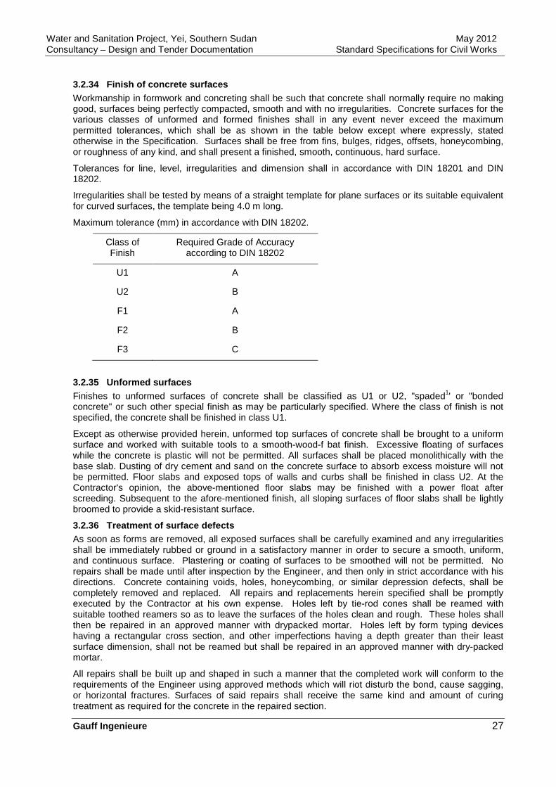
Water and Sanitation Project, Yei, Southern Sudan May 2012 Consultancy – Design and Tender Documentation Standard Specifications for Civil Works
Gauff Ingenieure 27
3.2.34 Finish of concrete surfaces Workmanship in formwork and concreting shall be such that concrete shall normally require no making good, surfaces being perfectly compacted, smooth and with no irregularities. Concrete surfaces for the various classes of unformed and formed finishes shall in any event never exceed the maximum permitted tolerances, which shall be as shown in the table below except where expressly, stated otherwise in the Specification. Surfaces shall be free from fins, bulges, ridges, offsets, honeycombing, or roughness of any kind, and shall present a finished, smooth, continuous, hard surface.
Tolerances for line, level, irregularities and dimension shall in accordance with DIN 18201 and DIN 18202.
Irregularities shall be tested by means of a straight template for plane surfaces or its suitable equivalent for curved surfaces, the template being 4.0 m long.
Maximum tolerance (mm) in accordance with DIN 18202.
Class of Finish
Required Grade of Accuracy according to DIN 18202
U1 A
U2 B
F1 A
F2 B
F3 C
3.2.35 Unformed surfaces Finishes to unformed surfaces of concrete shall be classified as U1 or U2, "spaded1' or "bonded concrete" or such other special finish as may be particularly specified. Where the class of finish is not specified, the concrete shall be finished in class U1.
Except as otherwise provided herein, unformed top surfaces of concrete shall be brought to a uniform surface and worked with suitable tools to a smooth-wood-f bat finish. Excessive floating of surfaces while the concrete is plastic will not be permitted. All surfaces shall be placed monolithically with the base slab. Dusting of dry cement and sand on the concrete surface to absorb excess moisture will not be permitted. Floor slabs and exposed tops of walls and curbs shall be finished in class U2. At the Contractor's opinion, the above-mentioned floor slabs may be finished with a power float after screeding. Subsequent to the afore-mentioned finish, all sloping surfaces of floor slabs shall be lightly broomed to provide a skid-resistant surface.
3.2.36 Treatment of surface defects As soon as forms are removed, all exposed surfaces shall be carefully examined and any irregularities shall be immediately rubbed or ground in a satisfactory manner in order to secure a smooth, uniform, and continuous surface. Plastering or coating of surfaces to be smoothed will not be permitted. No repairs shall be made until after inspection by the Engineer, and then only in strict accordance with his directions. Concrete containing voids, holes, honeycombing, or similar depression defects, shall be completely removed and replaced. All repairs and replacements herein specified shall be promptly executed by the Contractor at his own expense. Holes left by tie-rod cones shall be reamed with suitable toothed reamers so as to leave the surfaces of the holes clean and rough. These holes shall then be repaired in an approved manner with drypacked mortar. Holes left by form typing devices having a rectangular cross section, and other imperfections having a depth greater than their least surface dimension, shall not be reamed but shall be repaired in an approved manner with dry-packed mortar.
All repairs shall be built up and shaped in such a manner that the completed work will conform to the requirements of the Engineer using approved methods which will riot disturb the bond, cause sagging, or horizontal fractures. Surfaces of said repairs shall receive the same kind and amount of curing treatment as required for the concrete in the repaired section.
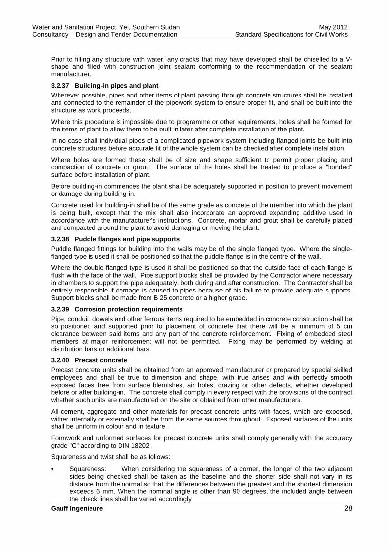
Water and Sanitation Project, Yei, Southern Sudan May 2012 Consultancy – Design and Tender Documentation Standard Specifications for Civil Works
Gauff Ingenieure 28
Prior to filling any structure with water, any cracks that may have developed shall be chiselled to a V-shape and filled with construction joint sealant conforming to the recommendation of the sealant manufacturer.
3.2.37 Building-in pipes and plant Wherever possible, pipes and other items of plant passing through concrete structures shall be installed and connected to the remainder of the pipework system to ensure proper fit, and shall be built into the structure as work proceeds.
Where this procedure is impossible due to programme or other requirements, holes shall be formed for the items of plant to allow them to be built in later after complete installation of the plant.
In no case shall individual pipes of a complicated pipework system including flanged joints be built into concrete structures before accurate fit of the whole system can be checked after complete installation.
Where holes are formed these shall be of size and shape sufficient to permit proper placing and compaction of concrete or grout. The surface of the holes shall be treated to produce a "bonded" surface before installation of plant.
Before building-in commences the plant shall be adequately supported in position to prevent movement or damage during building-in.
Concrete used for building-in shall be of the same grade as concrete of the member into which the plant is being built, except that the mix shall also incorporate an approved expanding additive used in accordance with the manufacturer's instructions. Concrete, mortar and grout shall be carefully placed and compacted around the plant to avoid damaging or moving the plant.
3.2.38 Puddle flanges and pipe supports Puddle flanged fittings for building into the walls may be of the single flanged type. Where the single-flanged type is used it shall be positioned so that the puddle flange is in the centre of the wall.
Where the double-flanged type is used it shall be positioned so that the outside face of each flange is flush with the face of the wall. Pipe support blocks shall be provided by the Contractor where necessary in chambers to support the pipe adequately, both during and after construction. The Contractor shall be entirely responsible if damage is caused to pipes because of his failure to provide adequate supports. Support blocks shall be made from B 25 concrete or a higher grade.
3.2.39 Corrosion protection requirements Pipe, conduit, dowels and other ferrous items required to be embedded in concrete construction shall be so positioned and supported prior to placement of concrete that there will be a minimum of 5 cm clearance between said items and any part of the concrete reinforcement. Fixing of embedded steel members at major reinforcement will not be permitted. Fixing may be performed by welding at distribution bars or additional bars.
3.2.40 Precast concrete Precast concrete units shall be obtained from an approved manufacturer or prepared by special skilled employees and shall be true to dimension and shape, with true arises and with perfectly smooth exposed faces free from surface blemishes, air holes, crazing or other defects, whether developed before or after building-in. The concrete shall comply in every respect with the provisions of the contract whether such units are manufactured on the site or obtained from other manufacturers.
All cement, aggregate and other materials for precast concrete units with faces, which are exposed, wither internally or externally shall be from the same sources throughout. Exposed surfaces of the units shall be uniform in colour and in texture.
Formwork and unformed surfaces for precast concrete units shall comply generally with the accuracy grade "C” according to DIN 18202.
Squareness and twist shall be as follows:
• Squareness: When considering the squareness of a corner, the longer of the two adjacent sides being checked shall be taken as the baseline and the shorter side shall not vary in its distance from the normal so that the differences between the greatest and the shortest dimension exceeds 6 mm. When the nominal angle is other than 90 degrees, the included angle between the check lines shall be varied accordingly
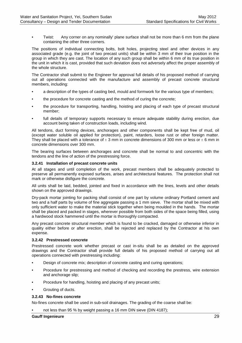
Water and Sanitation Project, Yei, Southern Sudan May 2012 Consultancy – Design and Tender Documentation Standard Specifications for Civil Works
Gauff Ingenieure 29
• Twist: Any corner on any nominally' plane surface shall not be more than 6 mm from the plane containing the other three corners.
The positions of individual connecting bolts, bolt holes, projecting steel and other devices in any associated grade (e.g. the joint of two precast units) shall be within 3 mm of their true position in the group in which they are cast. The location of any such group shall be within 6 mm of its true position in the unit in which it is cast, provided that such deviation does not adversely affect the proper assembly of the whole structure.
The Contractor shall submit to the Engineer for approval full details of his proposed method of carrying out all operations connected with the manufacture and assembly of precast concrete structural members, including:
• a description of the types of casting bed, mould and formwork for the various type of members;
• the procedure for concrete casting and the method of curing the concrete;
• the procedure for transporting, handling, hoisting and placing of each type of precast structural member;
• full details of temporary supports necessary to ensure adequate stability during erection, due account being taken of construction loads, including wind.
All tendons, duct forming devices, anchorages and other components shall be kept free of mud, oil (except water soluble oil applied for protection), paint, retarders, loose rust or other foreign matter. They shall be placed with a tolerance of ± 3 mm in concrete dimensions of 300 mm or less or ± 6 mm in concrete dimensions over 300 mm.
The bearing surfaces between anchorages and concrete shall be normal to and concentric with the tendons and the line of action of the prestressing force.
3.2.41 Installation of precast concrete units At all stages and until completion of the work, precast members shall be adequately protected to preserve all permanently exposed surfaces, arises and architectural features. The protection shall not mark or otherwise disfigure the concrete.
All units shall be laid, bedded, jointed and fixed in accordance with the lines, levels and other details shown on the approved drawings.
Dry-pack mortar jointing for packing shall consist of one part by volume ordinary Portland cement and two and a half parts by volume of fine aggregate passing a 1 mm sieve. The mortar shall be mixed with only sufficient water to make the material stick together when being moulded in the hands. The mortar shall be placed and packed in stages, wherever possible from both sides of the space being filled, using a hardwood stock hammered until the mortar is thoroughly compacted.
Any precast concrete structural member which is found to be cracked, damaged or otherwise inferior in quality either before or after erection, shall be rejected and replaced by the Contractor at his own expense.
3.2.42 Prestressed concrete Prestressed concrete work whether precast or cast in-situ shall be as detailed on the approved drawings and the Contractor shall provide full details of his proposed method of carrying out all operations connected with prestressing including:
• Design of concrete mix; description of concrete casting and curing operations;
• Procedure for prestressing and method of checking and recording the prestress, wire extension and anchorage slip;
• Procedure for handling, hoisting and placing of any precast units;
• Grouting of ducts.
3.2.43 No-fines concrete No-fines concrete shall be used in sub-soil drainages. The grading of the coarse shall be:
• not less than 95 % by weight passing a 16 mm DIN sieve (DIN 4187);
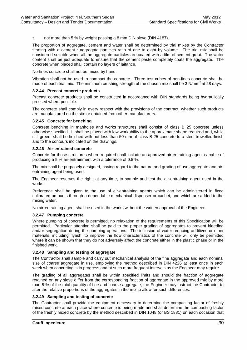
Water and Sanitation Project, Yei, Southern Sudan May 2012 Consultancy – Design and Tender Documentation Standard Specifications for Civil Works
Gauff Ingenieure 30
• not more than 5 % by weight passing a 8 mm DIN sieve (DIN 4187).
The proportion of aggregate, cement and water shall be determined by trial mixes by the Contractor starting with a cement : aggregate particles ratio of one to eight by volume. The trial mix shall be considered suitable when all the aggregate particles are coated with a film of cement grout. The water content shall be just adequate to ensure that the cement paste completely coats the aggregate. The concrete when placed shall contain no layers of laitance.
No-fines concrete shall not be mixed by hand.
Vibration shall not be used to compact the concrete. Three test cubes of non-fines concrete shall be made of each trial mix. The minimum crushing strength of the chosen mix shall be 3 N/mm2 at 28 days.
3.2.44 Precast concrete products Precast concrete products shall be constructed in accordance with DIN standards being hydraulically pressed where possible.
The concrete shall comply in every respect with the provisions of the contract, whether such products are manufactured on the site or obtained from other manufacturers.
3.2.45 Concrete for benching Concrete benching in manholes and works structures shall consist of class B 25 concrete unless otherwise specified. It shall be placed with low workability to the approximate shape required and, while still green, shall be finished with not less than 50 mm of class B 25 concrete to a steel trowelled finish and to the contours indicated on the drawings.
3.2.46 Air-entrained concrete Concrete for those structures where required shall include an approved air-entraining agent capable of producing a 5 % air-entrainment with a tolerance of 0.5 %.
The mix shall be purposely designed, having regard to the nature and grading of use aggregate and air-entraining agent being used.
The Engineer reserves the right, at any time, to sample and test the air-entraining agent used in the works.
Preference shall be given to the use of air-entraining agents which can be administered in fixed calibrated amounts through a dependable mechanical dispenser or cachet, and which are added to the mixing water.
No air-entraining agent shall be used in the works without the written approval of the Engineer.
3.2.47 Pumping concrete Where pumping of concrete is permitted, no relaxation of the requirements of this Specification will be permitted. Particular attention shall be paid to the proper grading of aggregates to prevent bleeding and/or segregation during the pumping operations. The inclusion of water-reducing additives or other materials, including flyash, to improve the flow characteristics of the concrete will only be permitted where it can be shown that they do not adversely affect the concrete either in the plastic phase or in the finished work.
3.2.48 Sampling and testing of aggregate The Contractor shall sample and carry out mechanical analysis of the fine aggregate and each nominal size of coarse aggregate in use, employing the method described in DIN 4226 at least once in each week when concreting is in progress and at such more frequent intervals as the Engineer may require.
The grading of all aggregates shall be within specified limits and should the fraction of aggregate retained on any sieve differ from the corresponding fraction of aggregate in the approved mix by more than 5 % of the total quantity of fine and coarse aggregate, the Engineer may instruct the Contractor to alter the relative proportions of the aggregates in the mix to allow for such differences.
3.2.49 Sampling and testing of concrete The Contractor shall provide the equipment necessary to determine the compacting factor of freshly mixed concrete at each place where concrete is being made and shall determine the compacting factor of the freshly mixed concrete by the method described in DIN 1048 (or BS 1881) on each occasion that

Water and Sanitation Project, Yei, Southern Sudan May 2012 Consultancy – Design and Tender Documentation Standard Specifications for Civil Works
Gauff Ingenieure 31
a set of test cubes is made and not less than once a day or as the Engineer may direct.
For each grade of concrete, works test cubes shall be made whenever required by the Engineer but not less frequently than as follows unless otherwise particularly specified:
• for concrete of grade more than B 10: one set of cubes per 25 m3 or part thereof concreted per day;
• for concrete of grade B 10 and less: one set of cubes per 10 batches or part thereof concreted per day.
Each set of cubes (six cubes per set) shall be made from a single sample taken from a randomly selected batch of concrete. Three cubes shall be tested 7 days after manufacture and three cubes 28 days after manufacture when requested by the Engineer and additional set of cubes shall be made for testing three days after manufacture.
Test reports shall be submitted to the Engineer in duplicate.
3.2.50 Compliance with specified requirements The concrete shall be deemed satisfactory provided that:
• The average 28 days strength determined from any group of four consecutive test cubes exceeds the specified characteristic strength by not less than 5 N/mm2 for grade B 10 concrete and 7.5 N/mm2 for grades more than B 10 (or one-half of the current margin for any grade where a reduced margin has been approved by the Engineer for that mix design);
• Each individual test result is greater than 85 % of the specified characteristic strength.
If only one cube result fails to meet the second requirement, that result may be considered to represent only the particular batch of concrete from which the cube was taken, provided that the average strength of the group satisfies the first requirement.
If more than one cube in a group fails to meet the second requirement or if the average strength of any group of four consecutive test cubes fails to meet the first requirement then all the concrete in all the batches represented by all such cubes shall be deemed not to comply with the strength requirements.
3.2.51 Non-compliance When the average strength of four consecutive test cubes fails to meet the first requirement, no further concrete from that mix shall be placed in the work and the Contractor shall establish the cause of the failure and apply such remedies as are necessary. The Contractor shall demonstrate by trial mixes and test cube results that the revised mix is in accordance with the specified requirements.
The Contractor shall, within 24 hours of the date of test, make proposals for agreement with the Engineer about action to be taken in respect of any concrete represented by test cubes which fail to meet either of the requirements. These proposals may include, but shall not be limited to, cutting and testing cores.
Concrete which is ultimately found not to comply with any of the requirements of the Specification shall be rejected and shall be broken out and replaced or otherwise dealt with as agreed with the Engineer at the expense of the Contractor.
Furthermore, the Engineer may order additional cement added to the mix immediately. The mixes used may also be changed whenever, in the opinion of the Engineer, such change is necessary or desirable to secure the required workability, density, impermeability, surface finish and strength, and the Contractor shall be entitled to no additional compensation because of such changes.
3.2.52 Cutting and testing of core samples As and where directed by the Engineer cylindrical core specimens of 150 mm nominal diameter shall be taken normal to the face of the hardened concrete for the purposes of examination and testing. The procedure for drilling, examination, measurement and testing for comprehensive strength shall be in accordance with DIN 1048. Prior to preparation for testing, the specimen shall be made available for examination by the Engineer. If the crushing strength of the specimen deter-mined in accordance with DIN 1048 is less than the characteristic strength at 28 days for the grade requirements in other respects, the concrete in that part of the works of which it is a sample shall be considered not to comply with the specified requirements.
Water and Sanitation Project, Yei, Southern Sudan May 2012 Consultancy – Design and Tender Documentation Standard Specifications for Civil Works
Gauff Ingenieure 32
3.2.53 Inspection procedures Before any lift of concrete is placed, the Contractor shall carry out an inspection to ensure that all preparations are complete, including the provision of the necessary equipment and personnel and shall ensure that sufficient materials are available to complete the works proposed.
After completion of this inspection, the work shall be offered for inspection by the Engineer, sufficient time being allowed for inspection and correction of any defects. No concrete shall be placed until the Engineer has inspected and approved the surfaces upon which the concrete is to be placed, the formwork and the reinforcing steel.
The Contractor shall institute a "pour card" system in which a card is made out for each lift of concrete and is initialled by the Contractor and Engineer indicating that the inspections have been carried out.
The "pour card" shall include spaces to identify the concrete being placed and to signify completion of the inspections by the Contractor and Engineer of the following items:
• preparation of surface on which concrete is to be placed;
• formwork;
• reinforcement;
• ready for concrete placing;
• inspection after removal of formwork (any remedial work shall be agreed and noted);
• curing procedures;
• completion of remedial work (if any).
3.2.54 Concrete protection system All structural concrete in contact with the ground shall be protected by one of the methods specified below. Unless otherwise specified, in-situ concrete surfaces which are to be protected shall have either U2 or F2 finish as appropriate.
Prefabricated membrane tanking:
The membrane shall be performed consisting of 1.5 mm thick rubber/bitumen compound formulated for use in hot climates, backed with 0.3 mm thick PVC sheet. The membrane shall adhere with watertight joints to itself at overlaps and to concrete surfaces prepared with suitable priming compound.
The membrane and primer shall be applied in accordance with the manufacturer’s instructions to horizontal, inclined and vertical surfaces.
After the blinding concrete has hardened, the membrane shall be applied, bitumen face downwards, and shall extend at least 200 mm beyond the outer limits of the structure. As soon as the membrane has been applied and before any reinforcement or structural concrete is placed, the membrane shall be covered by a sand/cement screed 50 mm thick, extending over the whole area of the base of the structure. The membrane projection of 200 mm shall be temporarily protected with a layer of board as specified below to prevent mechanical damage.
Alternatively a purpose made rock-proof non-compressible board may be used instead of screed if approved by the Engineer.
After the concrete structure has been constructed up to ground level and curing is completed, the surfaces, which will be in contact with the ground, or as detailed otherwise on the approved drawings, shall be primed with the material supplied by the membrane manufacturer. The vertical membrane shall be bonded onto the projection of the base membrane and terminated in a chase at the top completed with a rubber bitumen seal. Fillets and reinforcing strips shall be used.
Completed areas of vertical membrane shall be protected from mechanical damage during backfill operations by 12 mm thick cardboard, fibreboard or chipboard secured with suitable adhesive, or by concrete blockwork.
Made-in-place membrane tanking:
As an alternative to prefabricated membrane tanking on horizontal surfaces, the Contractor may propose to design, supply and install a made-in-place membrane of bitumen asphalt concrete laid on a
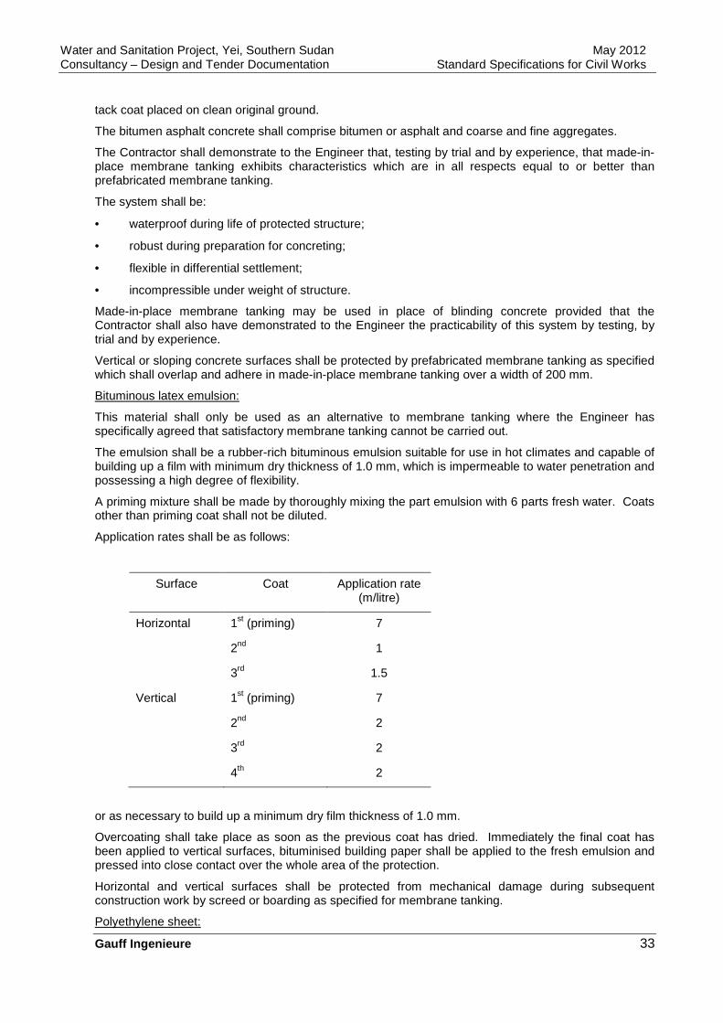
Water and Sanitation Project, Yei, Southern Sudan May 2012 Consultancy – Design and Tender Documentation Standard Specifications for Civil Works
Gauff Ingenieure 33
tack coat placed on clean original ground.
The bitumen asphalt concrete shall comprise bitumen or asphalt and coarse and fine aggregates.
The Contractor shall demonstrate to the Engineer that, testing by trial and by experience, that made-in-place membrane tanking exhibits characteristics which are in all respects equal to or better than prefabricated membrane tanking.
The system shall be:
• waterproof during life of protected structure;
• robust during preparation for concreting;
• flexible in differential settlement;
• incompressible under weight of structure.
Made-in-place membrane tanking may be used in place of blinding concrete provided that the Contractor shall also have demonstrated to the Engineer the practicability of this system by testing, by trial and by experience.
Vertical or sloping concrete surfaces shall be protected by prefabricated membrane tanking as specified which shall overlap and adhere in made-in-place membrane tanking over a width of 200 mm.
Bituminous latex emulsion:
This material shall only be used as an alternative to membrane tanking where the Engineer has specifically agreed that satisfactory membrane tanking cannot be carried out.
The emulsion shall be a rubber-rich bituminous emulsion suitable for use in hot climates and capable of building up a film with minimum dry thickness of 1.0 mm, which is impermeable to water penetration and possessing a high degree of flexibility.
A priming mixture shall be made by thoroughly mixing the part emulsion with 6 parts fresh water. Coats other than priming coat shall not be diluted.
Application rates shall be as follows:
Surface Coat Application rate (m/litre)
Horizontal 1st (priming) 7
2nd 1
3rd 1.5
Vertical 1st (priming) 7
2nd 2
3rd 2
4th 2
or as necessary to build up a minimum dry film thickness of 1.0 mm.
Overcoating shall take place as soon as the previous coat has dried. Immediately the final coat has been applied to vertical surfaces, bituminised building paper shall be applied to the fresh emulsion and pressed into close contact over the whole area of the protection.
Horizontal and vertical surfaces shall be protected from mechanical damage during subsequent construction work by screed or boarding as specified for membrane tanking.
Polyethylene sheet:

Water and Sanitation Project, Yei, Southern Sudan May 2012 Consultancy – Design and Tender Documentation Standard Specifications for Civil Works
Gauff Ingenieure 34
250 micron polyethylene sheet shall be placed against vertical or sloping surfaces of excavated ground before placing concrete directly against such surfaces.
Backfilling with sand against protected surfaces shall be carried out in such a manner that the protection is not damaged. Nevertheless, if such damage occurs, the damage shall be made good to the satisfaction of the Engineer.
3.2.55 Concrete protection procedures Details of concrete protection shall be shown by the Contractor on the working drawings. Such details shall include corners, overlaps, brick or board protection and details for curved faces, etc.
Concrete protection Systems proposed for use in the works shall be demonstrated by the Contractor to the Engineer for approval before submission of preliminary working drawings showing use of such systems in the works.
3.2.56 Machinery bases and grouting in Bases to take machinery and associated pipework shall be finished to class F 2 or U 2, as appropriate to the dimensions shown on the approved drawings or as ordered by the Engineer. The mounting surface of the base shall be steel floated to true and level planes.
The structural concrete on which the bases are to be erected shall be prepared by hacking and cleaning off.
Bases shall be tied to the structural concrete with vertical reinforcement. Horizontal reinforcement will also normally be provided at the level of the pockets for the holding down bolts.
Bolt pockets and lead-ins for grout shall be formed by means approved by the Engineer. Polystyrene formers will not be permitted. Where expand metal is used as a former it shall be left in.
When the machinery has been erected the bolt pockets shall on approval of the Engineer be completely filled using a mixture of 2 parts of sulphate resisting cement to 3 parts sharp sand by volume with sufficient water to form a thick creamy consistency.
The machinery will be run under the supervision of the Contractor and witnessed by the Engineer after the grout has hardened. When so directed the Contractor shall complete the grouting operation by filling the space between the top of the concrete and the underside of the machinery base plate.
3.2.57 Test for watertightness of water-retaining s tructures Water-retaining structures for water supply purposes shall satisfy the following tests for watertightness, before any external rendering or other finishes are applied (if any).
The water for testing shall fill the first 1.25 m and be filled as quickly as supply permits. Between this and top water level the rate of filling shall not exceed a steady rate of 300 mm per 24 hours unless otherwise directed. After filling to top water level no further water shall be introduced for 7 days and the structure shall satisfy the test if at the end of this week no leakage is apparent and the water level does not drop more than 3 mm plus an allowance for evaporation during the last 48 hours. Throughout the 48 hour period the water level shall be recorded every 4 hours by means of two hook and vernier gauges approved by the Engineer and sited as directed by him. In addition to the foregoing visible leakages will not be accepted.
Following satisfactory completion of the tests the structures shall be disinfected in accordance with DVGW working sheet W291.
3.3 REINFORCEMENT
3.3.1 Scope This Specification covers detailing, fabricating, supplying and placing of reinforcing steel and acces-sories for all cast in place and precast concrete.
The Contractor shall be entirely responsible for the correctness of bar schedules before arranging for the supply, cutting and bending of steel reinforcement.
3.3.2 Submissions The following submissions are required by this Specification:
Water and Sanitation Project, Yei, Southern Sudan May 2012 Consultancy – Design and Tender Documentation Standard Specifications for Civil Works
Gauff Ingenieure 35
(1) Test certificates
Manufacturer’s test certificates for each delivery of reinforcing steel. Each certificate shall show the country of origin and test.
Welding procedure tests.
Welder qualification tests.
(2) Data
Manufacturer's data on accessories and mechanical couplings.
(3) Drawings
All reinforcement drawings and bending schedules prepared by the Contractor.
3.3.3 Steel reinforcement Steel for reinforcement shall be of the following kinds in accordance to DIN 488 and DIN 1045 or BS 4449, BS 4461 and BS 4483 as appropriate.
• Type - IG - untreated plain round mild steel bars 220/340 GU
• Type - IR - untreated deformed round mild steel bars 220/340 RU
• Type - IIIU - untreated deformed round high yield steel bars 420/500 RU
• Type - IV G - welded hard drawn steel wire and other cold worked high bond barfabric500/550 GK
3.3.4 Steel wire and bars for prestressing Prestressing steel wire or bars shall be in accordance to DIN 4227.
3.3.5 Accessories The Contractor shall supply all accessories such as reinforcing steel supports, hold-downs, spreaders, hangers, tie wire and all other incidentals necessary to complete an acceptable installation of all concrete reinforcement. All accessories shall be of steel with the exception of spacers to maintain concrete cover to reinforcement against formed or blinded surfaces which shall be of concrete of same texture, colour and composition as cast-in-place concrete. Concrete spacers shall be in the form of a truncated cone or pyramid and shall be used with the larger face towards the reinforcing steel. The smaller face of a truncated cone or pyramid shall have minimum dimension of 50 mm.
3.3.6 Dowels Dowel shall be of the same size and spacing as bars with which they are lapped. Unless otherwise noted, the lap and embedment shall be 64 times bar diameter minimum of each. Dowels shall be wired or otherwise held in position. Dowels shall be installed prior to placing concrete. They shall not be placed into freshly placed concrete.
3.3.7 Detailing Steel reinforcement shall be as shown on the approved drawings. The Contractor shall be responsible for checking the drawings before cutting and bending reinforcement. When any information relating to reinforcement is missing or apparently incorrect, the Contractor shall remedy the missing or incorrect information to the approval of the Engineer.
3.3.8 Cutting and bending of reinforcement Bars shall be cut and bent in accordance with the provisions of DIN 1045. All bending shall be done cold with the use of an approved bending machine. Rebending of bars will not be permitted. Cut and bent bars shall be bundled and labelled for positive identification with the drawings and bending schedules, until they are incorporated into the work.
3.3.9 Storage of reinforcing bars and fabric The Contractor shall stack separately and label different types of reinforcement for positive identi-fication. Steel reinforcing bars shall be kept clean and shall be free from pitting, loose rust, mill scale, oil, grease, earth, paint, or any other material, which may impair the bond between the concrete and the reinforcement.

Water and Sanitation Project, Yei, Southern Sudan May 2012 Consultancy – Design and Tender Documentation Standard Specifications for Civil Works
Gauff Ingenieure 36
Reinforcing steel shall be stored and fabricated under cover on wooden or concrete supports such that the steel is elevated from the ground surface by a minimum of 150 mm.
3.3.10 Storage of prestressing wire and bars In addition to complying with the above storage requirements, the Contractor shall ensure that pre-stressing wire and bars are protected from mechanical damage by storing on time supports above a concrete slab, and shall ensure that during storage the wire and bars are kept properly coated with water soluble oil inside protective wrappings.
3.3.11 Fixing of reinforcement All reinforcement shall be securely and accurately fixed in positions shown on the approved drawings using approved spacer blocks or chairs. All intersections of bars shall be secured by using suitable clips or annealed iron wire, the ends being turned into the body of the concrete. The Contractor shall ensure that all reinforcement is maintained in position at all times, particular care being taken during placing of concrete.
Concrete cover to reinforcement shall be as specified in the table below. Correct concrete cover to reinforcement shall be maintained with the aid of approved spacer pieces.
Reinforcement in slabs shall be maintained in position by means of chairs at 90 cm centres maximum.
Reinforcement in walls with two layers of reinforcement shall be maintained in position by using 6 mm U or Z-shaped spacers at 180 cm centres maximum.
No part of the reinforcement shall be used to support formwork, access ways, working platforms, or the placing equipment or for the conducting of an electric current. Welding of reinforcement is subject to the Engineer' s permission.
3.3.12 Concrete cover Except as otherwise shown on the approved drawings reinforcement shall be installed with clearance coverage in centimetres as follows:
• All surfaces in contact with water or placed against soil: 5.0 cm
• Underside of slabs over water in enclosed conduits and beams and columns not exposed to soil or water: 4.0 cm
• Surfaces exposed to air and all interior surfaces in pipe galleries and dry rooms: 3.0 cm
3.3.13 Tolerances Tolerances in placing reinforcement shall be:
• for members 60 cm or less in depth ± 0.5 cm
• for members more than 60 cm in depth ± 1.5 cm
3.3.14 Inspection and testing When required by the Engineer, the Contractor shall take samples from reinforcement delivered to site and shall arrange for the samples to be tested by an approved testing agency. Test certificates from that agency shall be submitted to the Engineer.
The Engineer or his authorized representative may require witnessing such testing and also routine testing at the manufacturer's works.
The Contractor shall be responsible for all checking and inspection of reinforcement before preparations for placing concrete are offered for inspection by the Engineer.
3.3.15 Straightening Reinforcing steel shall not be straightened or rebent in a manner that will injure the material. Bars with kinks or bends not shown on the drawings shall not be used.
3.3.16 Approval by Engineer In no case shall any reinforcing steel be covered by concrete until the amount and position of the reinforcement have been checked by the Engineer and his permission given to proceed with concreting.
Water and Sanitation Project, Yei, Southern Sudan May 2012 Consultancy – Design and Tender Documentation Standard Specifications for Civil Works
Gauff Ingenieure 37
3.4 FORMWORK
3.4.1 Scope This section covers the supply, erection and removal of formwork, the finishes to be attained and the remedial action to be taken to the finished concrete after removal of formwork.
3.4.2 Submissions When required by the Engineer, the Contractor shall submit calculations and designs for formwork including layout of panels, before fabrication has commenced.
3.4.3 General Formwork shall be constructed of timber, sheet metal or other approved material. The Contractor shall also furnish all struts, braces and ties to withstand the placing and vibrating of concrete and the effects of weather.
Except as otherwise expressly approved by the Engineer, all material brought on the job site as forms, struts or braces shall be new material. All forms shall be smooth surface forms and shall be of good quality.
For each class of finish the Contractor shall provide sample panels to the satisfaction of the Engineer. If the sample panels do not meet the requirements, the Contractor shall perform new samples.
Sample panels shall be not less than 0.30 m thick and about 2 m2 in area.
All surface finishes of constructed concrete shall be equal to the sample panels approved by the Engineer.
3.4.4 Form ties Form ties for use in water-retaining structures shall incorporate a diaphragm not less than 50 mm diameter welded to the mid point of the tie, designed to prevent water passing along the tie.
Form ties with integral waterstops shall be provided in a cork or other suitable means for forming a conical hole to ensure that the form tie may be broken off back of the face of the concrete. The maximum diameter of removable cones for rod ties, or of other removable form tie fasteners having a circular cross section, shall not exceed 40 mm and all such fasteners shall be such as to leave holes of regular shape for reaming. Holes left by the removal of fasteners having a circular cross section, shall not exceed 40 mm and all such fasteners shall be such as to leave hole of regular shape for reaming. Holes left by the removal of fasteners from the ends of snap-ties or form ties shall be reamed with suitable toothed reamers so as to leave the surfaces of the holes clean and rough before being filled with mortar. Wire ties for holding forms will not be permitted. No form-tying device or part thereof, other than metal, shall be left embedded in the concrete, not shall any tie be removed in such manner as to leave a hole extending through the interior of the concrete member. The use of snap-ties which cause spalling of the concrete upon form stripping or tie removal will not be permitted. If steel panel forms are used, rubber grommets shall be provided where the ties pass through the form in order to prevent loss of cement paste. Where metal rods extending through the concrete are used to support or to strengthen forms, the rods shall remain embedded and shall terminate not less than 50 mm back from the surface in the case of reinforced concrete and 150 mm in the case of unreinforced concrete.
3.4.5 Number of forms A sufficient number of forms of each kind shall be provided to permit the required rate of progress to be maintained. Whenever, in the op inion of the Engineer, additional forms are necessary to maintain the progress schedule, such additional forms shall be provided by the Contractor at his own expense. The design and inspection of concrete forms, falsework and shoring shall comply with the applicable standards.
3.4.6 Design The Contractor shall be responsible for the adequacy and safety of formwork.
All forms shall be true in every respect to the required shape and size, shall conform to the established alignment and grade, and shall be of sufficient strength and rigidity to maintain their position and shape under the loads and operations incident to placing and vibrating the concrete. Suitable and effective means shall be provided on all forms for holding adjacent ends of panels and section rightly together and in accurate alignment so as to prevent the formation or ridges, fins, offsets, or similar surface

Water and Sanitation Project, Yei, Southern Sudan May 2012 Consultancy – Design and Tender Documentation Standard Specifications for Civil Works
Gauff Ingenieure 38
defects in the finished concrete. Plywood, 15 mm and greater in thickness, may be fastened directly to studding if the studs are spaced close enough to prevent visible deflection marks in the concrete. The forms shall be tight so as to prevent the loss of water, cement and fins during placing and vibrating of the concrete. Adequate clean-out holes shall be provided at the bottom of each lift of forms. The size, number and location of such clean-outs shall be subject to the approval of the Engineer.
On formwork to external faces which will be permanently exposed, all horizontal and vertical form-work joints shall be so arranged that joint lines shall form a uniform pattern on the face of the concrete. The Contractor shall make up the formwork from standard sized manufactured formwork panels, the size of such panels shall be approved by the Engineer before they are used in the construction of the work. The finished appearance of the entire elevation of the structure and adjoining structures shall be considered when planning the pattern of joint lines caused by formwork and by construction joints to ensure continuity of horizontal and vertical lines.
Concrete construction joints will not be permitted at locations other than those shown on the approved drawings, except as may be approved by the Engineer. When a second lift is placed on hardened concrete, special precautions shall be taken in the way of the number, location and tightening of ties at top of the old lift and bottom of the new to prevent any unsatisfactory effect whatsoever on the concrete. Pipe stubs and anchor bolts shall be set in the forms where required.
Unless otherwise shown, exterior corners in concrete members shall be provided with 20 mm x 20 mm chamfers. Re-entrant corners in concrete members shall not have fillets unless otherwise shown.
3.4.7 Vertical surfaces All vertical surfaces of concrete members shall be formed, except where placement of the concrete against the ground is called for on the drawings or explicitly authorized by the Engineer. Permission for placing concrete against trimmed ground in lieu of forms will be granted only for members of comparatively limited height and where the character of the ground is such that it can be trimmed to the required lines and will stand securely without caving or sloughing until the concrete has been placed.
3.4.8 Formed surfaces - class of finish Finishes to formed surfaces shall be classified as Fl, F2 or F3 as finish specified in elsewhere. Where the class of finish is not specified the concrete shall be finished to class F 2.
3.4.9 Erection of formwork All formwork shall be soundly constructed, firmly supported, adequately strutted, braced and tied to withstand the placing and vibrating of concrete and the effects of weather. Formwork shall not be tied to or supported by reinforcement.
Faces of formwork in contact with concrete shall be free from adhering foreign matter, projecting nails and the like, splits or other defects, and all form-work shall be clean and free from standing water, dirt, shavings, chippings or other foreign matter. Joints shall be sufficiently watertight to prevent the escape of mortar or the formation of fins or other blemishes on the face of the concrete.
All exposed exterior angles on the finished concrete of 90 degrees or less shall be given 20 mm by 20 mm chamfers.
Formwork shall be provided for the top surfaces of sloping work where the slope exceeds 15 degrees from the horizontal (except where such top surface is specified as spaded finish) and shall be anchored to enable the concrete to be properly compacted and to prevent air being trapped.
Formwork in contact with the concrete shall be treated with a suitable non-staining mould oil prior to reinforcement and concrete placement to prevent adherence of the concrete except where the surface is subsequently to be rendered.
Care shall be taken to prevent the oil from coming in contact with reinforcement or with concrete at construction joints. Surface retarding agents shall not be used unless approved by the Engineer.
Where ties are built into the concrete for the purpose of supporting formwork, the whole or part of any such supports shall be capable of removal so that no part remaining embedded in the concrete shall be nearer than 50 mm from the surface in the case of reinforced concrete and 150 mm in the case of unreinforced concrete. Holes left after removal of such supports shall be neatly filled with well rammed dry-packed mortar.
Water and Sanitation Project, Yei, Southern Sudan May 2012 Consultancy – Design and Tender Documentation Standard Specifications for Civil Works
Gauff Ingenieure 39
Openings for inspection of the inside of the formwork, for the removal of water used for washing down and for placing concrete shall be provided and so formed as to be easily closed before or during placing concrete. Before placing concrete all bolts, pipes or conduits or any other fixtures which are to be built in shall be held fast by fixing to the formwork or otherwise. Holes shall not be cut in any concrete without prior approval of the Engineer.
3.4.10 Maintenance of forms Forms shall be maintained at all times in good condition, particularly as to size, shape, strength, rigidity, tightness and smoothness of surface. Forms, when in place, shall conform to the established alignment and grades. Before concrete is placed, the forms shall be thoroughly cleaned. The forms' surfaces shall be treated with a non-staining mineral oil or other lubricant approved by the Engineer. Any excess lubricant shall be satisfactorily removed before placing the concrete. In addition, all forms shall be given a preliminary oil treatment by the manufacturer or shall be oiled by the Contractor at least two weeks in advance of their use. Care shall be exercised to keep oil off the surfaces of steel reinforcement and other metal items to be embedded in concrete. Forms may be re-used if in good condition and if approved by the Engineer.
Light sanding between uses shall be required wherever necessary in the opinion of the Engineer to obtain uniform surface texture on all exposed concrete surfaces. Exposed concrete surfaces are defined as surfaces, which are permanently exposed to view. In the case of forms for the inside wall surfaces of hydraulic structures, unused tie rod holes shall be covered with metal caps or shall be filled by other methods approved by the Engineer.
3.4.11 Removal of formwork Formwork shall be so designed as to permit easy removal without resorting to hammering or levering against the surface of the concrete.
The period of time elapsing between the placing of the concrete and the striking of the formwork shall be as approved by the Engineer after consideration of the loads likely to be imposed on the concrete and shall in any case be not less than the period stated in DIN1045.
The Contractor shall be held responsible for any damage arising from removal of formwork before the structure is capable of carrying its own weight and any incidental loading.
3.4.12 Building in plant The Contractor shall erect all formwork, struts and other temporary work to enable plant to be built in, and such formwork shall be designed to allow placing of the concrete, mortar or grout so as to fill the voids completely, and to enable air to escape from any cavities during filling. The formwork shall be sealed against pipework and other items of plant to prevent leakage of grout. Formwork shall be supported independently of all plant and pipework. The Contractor shall use such templates and moulds as are necessary to achieve the accurate positioning of such items as penstocks and access cover.
3.4.13 Inspection and testing Before concrete is placed against any formwork, the formwork shall be inspected by the Contractor and offered for inspection and approval by the Engineer.
If a “pour-card” system is in operation, the card shall be signed by the Contractor and submitted to the Engineer with the request for inspection of the formwork.
3.5 JOINTS
3.5.1 Construction joints A construction joints is defined as a joint in the concrete introduced for convenience in construction at which special measures are taken to achieve subsequent continuity without provision for further relative movement.
Concrete placed to form the face of a construction joint shall have all laitance removed and the large aggregate exposed prior to the placing of fresh concrete.
The laitance shall wherever practicable be removed when the concrete has set but not hardened by spraying the concrete surface with water under pressure or brushing with a wire brush sufficient to remove the outer mortar skin and expose the large aggregate without being disturbed. Where the
Water and Sanitation Project, Yei, Southern Sudan May 2012 Consultancy – Design and Tender Documentation Standard Specifications for Civil Works
Gauff Ingenieure 40
laitance cannot be removed due to hardening of the concrete, the whole of the concrete surface forming the joint shall be treated by high pressure water jet, sand blasting, use of a needle gun or a scaling hammer to remove the surface laitance.
3.5.2 Performance of construction joints and lifts General
Bonding shall be required at all joints in walls, except where otherwise shown or specified.
Concrete next to waterstops shall be placed in accordance with below.
Construction joint sealant
Where required, construction joints in floor slabs shall be formed with grooves which shall be filled with a construction joint sealant. The materials used for forming the grooves shall be left in the grooves until just before the grooves are cleaned and filled with joint sealant. After removing the form from the grooves, all laitance and fins shall be removed and the grooves shall be sandblasted. The grooves shall be allowed to become thoroughly dry, after which they shall be blown out, immediately thereafter, they shall be primed and filled with the construction joint sealant. The primer used shall be supplied by the same manufacturer supplying the sealant. No sealant will be permitted to be used without a primer. Care shall be used to completely fill the sealant grooves. Areas designated to receive a sealant fillet shall be thoroughly cleaned, as outlined for the grooves, prior to application of the sealant. The sealant shall be two-pack polyurethane polymer designed for bounding to concrete which is continuously submerged in water. No material will be acceptable which has an unsatisfactory history as to bond or durability when used in the joints of hydraulic structures. Prior to ordering the sealant material, the Contractor shall submit to the Engineer for approval sufficient data to show general compliance with the specification requirements.
The material shall meet the following requirements:
• Work life 45-90 mins. time to reach “A” hardness (at 250C, 200 gr quantity) 20 hrs max.
• Ultimate hardness: 20-40 shore "A'
• Tensile strength: 16 kg/cm2 min.
• Ultimate elongation: 400 5 mins.
• Tear resistance: 120 kg per cm of thickness
Alternatively a two-pack polysulphide may be used as a sealant.
Certified test reports from the sealant manufacturer on the actual batch of material being supplied indicating compliance with the above requirements shall be furnished to the Engineer before the sealant is used on the job. The primer and sealant shall be placed strictly in accordance with the recommendations of the manufacturer, taking special care to properly mix the sealant prior to applica-tion. Before any sealant is placed, the persons carrying out the work shall be carefully instructed as to the proper method of application. All sealant shall cure at least 7 days before the structure is filled with water.
Waterstops
Materials and manufacture
Central waterstops shall have 10 mm thick webs and be extruded from an elastomeric polyvinylchloride compound containing the necessary plasticisers, resins, stabilizers and other materials necessary to meet the requirements of these Specifications. No reclaimed or scrap material shall be used. The waterstop manufacturer shall furnish to the Engineer current test reports and a written certification that the material to be supplied meets the following physical requirements:
Unit Value
Physical property (sheet material):
Tensile strength min (kg/cm2) 120
Ultimate elongation min (%) 350
Water and Sanitation Project, Yei, Southern Sudan May 2012 Consultancy – Design and Tender Documentation Standard Specifications for Civil Works
Gauff Ingenieure 41
Stiffness in flexure min (kg/cm2) 28
28 Accelerated extraction:
Tensile strength min (kg/cm2) 105
Ultimate elongation min (%) 300
Finished waters top:
Tensile strength min (kg/cm2) 100
Ultimate elongation min (%) 280
Splices and joints
Prior to use of the waterstop material in the field, a cross section sample of a fabricated waterstop of each size or shape to be used shall be submitted to the Engineer for approval. These samples shall be fabricated so that the material and workmanship represent in all respect the fittings to be furnished under this contract. When tested, they shall have a tensile strength across the joints equal to at least 42 kg/cm2.
Field splices and joints shall be made in accordance with the waterstop manufacturer's instructions using a thermostatically controlled heating iron.
Flat-steel waterstops
For flat-steel waterstops the thickness shall be less than 5 mm. Adequate means shall be provided for anchoring the waterstop in concrete. In placing flat-steel waterstops in the forms, means shall be provided to prevent them from being folded over by the concrete as it is placed. Horizontal waterstops shall be held in place with continuous supports to which the top edge of the waterstop shall be tacked. Vertical waterstops shall be held in place with light wire ties at 45 cm centres which shall be passed through the edge of the waterstop and tied to the two curtains of reinforcing steel. In placing concrete around waterstops, concrete shall be worked under the waterstops by hand so as to avoid the formation of air and rock pockets.
3.5.3 Movement joints generally Movement joints for expansion and contraction shall be constructed in accordance with the details and to the dimensions shown on the approved drawings or where otherwise ordered by the Engineer and shall be formed of the elements specified.
The Contractor shall pay particular attention to the effects of climatic extremes about the works on any material which he may desire to use in any movement joints and shall submit for approval by the Engineer his proposals for the proper storage handling and use of the said materials having due regard to any recommendations in this connection made by manufacturers.
Waterstops shall conform to the requirements specified elsewhere.
Waterstops shall be incorporated into all expansion and contraction joints in units which retain or exclude liquids.
Different types of waterstop material shall not be used together in any complete installation.
Waterstops shall be fabricated into the longest practical units at the supplier's works and shall be continuous throughout the structure below highest water level. Intersections and joints shall be factory made where possible.
Waterstops shall be carefully maintained in the position and supported on accurately profiled stop boards to create rigid conditions.
Joint filler shall be either cork/bitumen joint filler or cellular joint filler. Cork/bitumen joint filler shall be waterproof and rot proof and shall not extrude as a result of compression. Cork joint filler shall compress to less than 50 % of its original thickness with immediate recovery to 80 % or more of its original thickness.
Cellular joint filler shall be used only for joints of low horizontal loading and shall be a preformed low compression joint filler made from foam rubber. Cellular joint filler shall recover to its original thickness after each loading and unloading.
Water and Sanitation Project, Yei, Southern Sudan May 2012 Consultancy – Design and Tender Documentation Standard Specifications for Civil Works
Gauff Ingenieure 42
The joint filler shall be fixed to the required dimensions of the joint cross section and shall provide a firm base for the joint sealer. Where the depth of joint between the concrete surface and the waterstop does not exceed 500 mm, a filler shall be placed in single depth sections.
Sealing of movement joints shall be carried out only when adjacent concrete surfaces are perfectly dry and as long after the concrete has been set as possible. Immediately before the application of the joint sealer the groove protection batten shall be removed in such lengths as represent a single day's work for sealing the joints.
The joint grooves shall be cleaned, adequately primed and filled with approved sealer strictly in accordance with the manufacturer's instructions and on joints of 25 mm and larger with a shape factor of 2:1 (width to depth).
On permanently exposed areas of structures joint sealing is to be carried out with the aid of masking tape to form neatly defined surface limits to the sealer.
3.5.4 Sliding planes Sliding planes on the concrete and joint blinding layers shall consist of a bitumen sand mixture 1 to 4 by volume spread evenly 3 mm thick over the carpet coat or of building paper either of which shall be applied immediately before the structural floor is concreted and shall be at all times suitably protected. Where building paper is used the concrete formation carpet shall be finished with a steel trowel to give a smooth surface.
Sliding joints shall consist of two layers of purpose made preformed plastic membrane which when in contact shall give a coefficient of friction of not more than 0.2 when subjected to a load of 270 Kg/m2. Where formed in concrete structures the lower joint bedding surface shall be steel float finished to a smooth true surface.
4 MASONRY AND PLASTER WORK
4.1 SCOPE
This Specification covers the requirements for masonry work and plaster work.
4.2 MASONRY WORK
4.2.1 Materials Bricks and blocks
Bricks shall be clay facing bricks manufactured locally. The quality shall correspond to DIN 105.
Blocks shall be dense concrete blocks to DIN 18153 with a compressive strength of > 7.5 N/mm2. Bricks and blocks shall be hard, sound, square and clean with sharp well defined arises.
The Contractor shall submit samples of each type of brick and block and obtain approval before placing orders with suppliers.
Strength test certificates performed on the basis of appropriate DIN standards for all bricks and blocks shall also be submitted to the Engineer.
Reinforcement
Reinforcement for brickwork shall be in accordance with DIN 488, DIN 1045 and DIN 1053. Reinforcement for brickwork shall be Type I G or Type III U standard. Reinforcement shall be detailed, stored and tested as specified under ‘Reinforcement for concrete.’
Fixings
Stainless steel for sheet, strip, plate and bars shall be “1.4302 E 23” quality to DIN 17440.
Sand, cement, water
Sand shall be clean and sharp coarse grit, fresh water river or pit sand conforming in all respects to DIN 1053 and DIN 18550 and shall be re-washed in site if the silt loam or clay content exceeds the requirements described in DIN 4226. The sand shall be obtained from a source approved by the
Water and Sanitation Project, Yei, Southern Sudan May 2012 Consultancy – Design and Tender Documentation Standard Specifications for Civil Works
Gauff Ingenieure 43
Engineer.
Cement shall be sulphate resisting Portland cement as specified in DIN 1164.
Water shall be clean and free from impurities and shall at regular intervals be tested to ensure compli-ance with DIN 4030 and DIN 38404.
Mortar mix
Masonry mortar for setting blocks and bricks shall be of the quality of Group III according to DIN 18550. The proportion shall be 1 part cement to 4 parts sand or as otherwise approved by the Engineer.
Mortar shall be mixed with water in an amount compatible with workability. Mortar constituents shall be measured by volume, using clean gauge boxes made to size to suit volumes required. Gauge boxes shall be overfilled and excess material struck off with a straight edge.
Mortar shall be mixed in a mechanically operated mortar mixer for at least three minutes after all ingredients are in the drum, and at least long enough to make a thorough, complete, intimate mix of the materials.
The mixing of mortar by hand will be permitted only when the quality of hand mixing is comparable to mechanical mixing. The Engineer reserves the right to reject hand mixing and require all mixing to be by mechanical means.
Mortar shall be used within two hours of discharge from the mixer at normal temperature and on no account shall mortar be used after the initial set has taken place. Reconstitution of mortar will not be permitted. Mortar boxes shall be cleaned out at the end of each day and all tools shall be kept clean.
Coloured mortar shall be mixed as specified using cement and sand in the above proportions with the addition of a coloured pigment in accordance with appropriate DIN standards.
4.2.2 Workmanship General
All masonry shall be laid plumb and true to lines and built to the thickness and bond required with courses level and joints and bond uniform. Masonry shall be carried up in a uniform manner. No one portion shall be raised more than a meter above adjacent portions, except with the approval of the Engineer.
Sample panels 1 m2 shall be prepared for each type of facing brickwork/blockwork, including jointing or pointing, and the Contractor shall obtain approval before proceeding with the work.
Hot weather:
Bricks and blocks shall be stacked on a level hardstanding so as to prevent the absorption or ingress of water. Suitable shading shall be provided to prevent high temperatures existing within the brick and block stacks.
Dry weather:
Clay brickwork and blockwork shall be kept wet to the minimum extent necessary to prevent mortar drying out prematurely.
Wet weather:
Freshly laid brickwork/blockwork shall be protected during interruption through rain and at the completion of each day's work.
Facework shall be kept clean during construction and until practical completion. Scaffold boards shall be kept clear of the building at night and during heavy rain. Rubbing to remove stains will not be permitted.
All bricks shall be wetted before being laid.
Clay bricks shall not be used until completely cold from the kiln.
Facing bricks of varying colour shall be distributed evenly throughout the work so that no patches appear. Different deliveries which vary in colour shall be mixed to avoid horizontal stripes.
Brickwork shall be carried up, including both skins of cavity work where applicable, with no portion more
Water and Sanitation Project, Yei, Southern Sudan May 2012 Consultancy – Design and Tender Documentation Standard Specifications for Civil Works
Gauff Ingenieure 44
than 1.5 m above another at any time, racking back between levels.
Brickwork shall be gauged for four courses to 300 mm including joints.
Bricks shall be laid on a full bed of mortar and all joints filled. Bed and vertical joints shall be of equal and consistent thickness.
Solid bricks shall be laid on a full bed of mortar with joints filled solid to a consistent thickness not more than 12 mm.
Should single frogged bricks be permitted, they shall be laid with the frog upwards and these shall be filled with mortar. Double frogged bricks shall not be used.
Courses shall be kept level and perpends vertical and in line. Quoins and other angles shall be plumbed as the work proceeds.
Templates shall be used for forming openings in face work where doors and windows are not built in at the time.
Brickwork and blockwork abutting concrete columns, walls and beams shall be tied with stainless steel ties in accordance with the relevant references and as directed by the design. Additional ties shall be supplied at openings. Walls which are to be fair face shall have selected bricks and blocks with perfect arises and flat surfaces and with faces in line.
Bonding
Where not otherwise required, bricks throughout the work shall be laid with the cross joints in any course not less than a quarter of a brick from those in the course below.
All brick and blockwork shall be laid in a regular pattern to the satisfaction of the Engineer.
Exposed concrete block
Concrete block shall be laid in "stack" bond, unless otherwise indicated, with joints not exceeding 1.0 cm and uniform throughout and finished slightly concave and smooth, tool dense and neat (no finger pointing allowed). All blocks shall be laid in a full bed of mortar applied to shells only. Mortar shall be applied to the vertical joint of blocks already set in the wall and all contact faces of the unit to be set. Each unit shall be placed and shoved against the block previously laid so as to produce a well-compacted vertical mortar joint for the full shell thickness. Moisture contents of blocks shall not exceed 35 % when laid. Intersection bearing walls shall be tied together with metal ties at one meter vertical spacing. Bends of tie bars and reinforcing shall be embedded in cells filled with mortar. Where indicated, concrete blocks shall be reinforced and concrete block lintel types shall be built in.
All necessary block cutting shall be neatly done by saws.
Control joints shall be installed at the intersection of block walls with structural concrete and elsewhere where such joints are useful. Joints not detailed otherwise shall be raked out to a depth of 2 cm for the full height of the wall and caulked. Maximum length between joints shall be 10 m.
Joints are to be examined to locate cracks, holes or other defects and all such defects shall be filled with mortar and pointed.
Concrete blocks to be plastered
Concrete block walls to be plastered may be laid with bonds described above. Joints are to be left rough to assist in bounding of plaster. Otherwise, concrete block masonry shall conform to previous paragraph "Exposed concrete block". Control joints in plastered block walls shall be carried through the plaster. The joint shall not be plastered.
Brickwork
Solid brick shall be laid in common bond with all joints filled solidly with mortar and backs fully purged to form solid masonry structures. Joints of walls to receive plaster shall be lightly raked to provide a bond for plaster. Solid brick shall be plastered only when so indicated on the approved drawings or required in the particular specifications.
Otherwise brickwork masonry shall conform to the paragraph 4.2.2.3 "Exposed concrete block". Control joints in plastered brick walls shall be carried through the plaster. The joint shall not be plastered.
Water and Sanitation Project, Yei, Southern Sudan May 2012 Consultancy – Design and Tender Documentation Standard Specifications for Civil Works
Gauff Ingenieure 45
Lintels, ties, miscellaneous
The Contractor shall build in or provide all miscellaneous items to be set in masonry including frames, lintels, reinforcing steel, electrical boxes and fixtures, sleeves, grilles, anchors and other miscellaneous items. All anchorage, attachments and bonding devices shall be set so as to prevent stoppage and shall be completely covered with mortar.
Wired butterfly and double triangle type wall ties will not be permitted in any wall. Wall ties shall be stainless steel strip, but of a twist type for the leaves of any cavity walls.
Padstones shall be bedded in mortar of the same strength as the adjacent wall, to give a level top surface.
Grouting
Grout and cement mortar for setting structural steel columns, railings, frames in walls and where otherwise required shall be done with mortar as hereinbefore specified. Before placing grout thoroughly clean all surfaces.
Grout shall be tamped into place with a blunt tool to fill the entire void. In the event space does not permit tamping, the Contractor shall build the necessary forms and place grout by pouring from one side only. When grout is placed by pouring a head of grout shall be maintained in the form. Grout shall be kept wet for three days and after the temporary supports adjusting wedges are removed the empty space shall be grouted and the surrounding grout pointed.
Cleaning
Masonry work, to be exposed, shall be thoroughly cleaned. Mortar smears and droppings on concrete block walls shall be dry before removal with a trowel. Masonry work may be cleaned using a mild muriatic acid solution.
Damp-proof courses
As a minimum requirement, damp-proof courses shall be in accordance with DIN 4117 and DIN 4122.
Bituminous sheet damp-proof courses shall be laid on a level bed of cement mortar with a minimum lap of 75 mm at angles and joints and neatly pointed in matching mortar on exposed edges. Horizontal and sloping damp-proof coursing over door openings shall be in single pieces of material of a length to extend 225 mm at both sides beyond the width of the frame.
Waterproof building paper
Waterproof building paper shall be laid beneath structural concrete. The paper shall be laid with 150 mm lapped joints which shall be treated and sealed with an approved bituminous solution. The weight of the paper shall not be less than 0.3 kg/m2.
Measurement for payment
Not used
4.3 RENDERING AND PLASTERING
4.3.1 General The work required under this Specification shall include all labour, materials, equipment, scaffolding etc., required to complete all internal and external plastering specified herein.
On completion, all surfaces shall be left in a neat and clean condition before handing over.
Materials, workmanship and construction shall be in accordance with the requirements of DIN 18550.
Work shall not be started or continued when the air temperature exceeds 400C.
4.3.2 Materials Sand shall be clean and sharp course grit, fresh water river or pit sand conforming in all respects to DIN 1053 and DIN 18550 and shall be re-washed on site if the silt loam or clay content exceeds the requirements described in DIN 4226. The sand shall be obtained from a source approved by the Engineer.
Water and Sanitation Project, Yei, Southern Sudan May 2012 Consultancy – Design and Tender Documentation Standard Specifications for Civil Works
Gauff Ingenieure 46
Cement shall be sulphate resisting Portland cement as specified in DIN 1164.
Water shall be clean and free from impurities and shall at regular intervals be tested to ensure compliance with DIN 4030 and DIN 38404.
4.3.3 Mixing Plaster shall be mixed with proportions according to DIN 18550.
Plaster shall be mixed with water in an amount compatible with workability.
Plaster constituents shall be measured by volume.
Plaster shall be mixed in a mechanically operated plaster mixer at least long enough to make a thorough, complete, intimate mix of the materials.
The mixing of plaster by hand shall not be permitted.
Bunkers, gauge boxes, gauging boards, etc. shall be thoroughly cleaned after each mix.
Mixer drums shall be thoroughly washed out at least four times a day if the mixer is in continuous use, and after each batch if not in continuous use. All tools shall be kept clean, and care taken to ensure that fresh plaster is not contaminated with set plaster.
4.3.4 Preparation Surfaces that are to receive plaster shall be carefully examined by the Contractor and any unsatisfactory surface shall be repaired as directed by the Engineer.
Where finished surfaces such as tile, lighting or other fixtures have been installed prior to plastering they shall be protected from damage during plastering. Protection shall consist of covering with a nonstaining building paper or polyethylene sheet. Protection shall be removed when plaster work is completed.
Concrete masonry and brick surfaces shall have sufficient roughness to provide proper bond and shall be dampened by brushing or spraying with water followed by plastering.
4.3.5 Finish Finishing coats shall be trowelled to a smooth and even finish.
4.3.6 Tolerances All surfaces shall be true to line, level, plumb and all junctions, angles and arises truly square. On two or three coat work, the plaster surface shall not show any deviation greater than specified in DIN 1 8202 for accuracy class B.
4.3.7 Connection of work Completion of work shall be as follows:
Curing:
Cement sand plasters shall be kept moist by sprinkling with water at regular intervals for a period of at least three days and until no powdery particles are present.
The Contractor shall plan his work such that rendering and plastering work is not carried out at extreme temperatures.
Defects:
Work shall be free of all defects, and any work which shows signs of blistering, bond failure, hollow patches, flaking, peeling, cracking, crazing, grinning, tool marks, discolouration or any other defects will not be accepted, and shall be removed and replaced with acceptable work.
Upon completion of the work, all plaster surfaces shall be cleaned and all rubbish, debris and excess material and equipment shall be removed.
4.3.8 Thickness and workmanship All plaster shall be applied according to the following thicknesses. Additional thickness will be required for any unevenness in the masonry surface.
Location Thickness of Coat (mm) Total Thickness
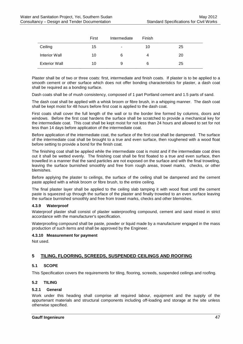
Water and Sanitation Project, Yei, Southern Sudan May 2012 Consultancy – Design and Tender Documentation Standard Specifications for Civil Works
Gauff Ingenieure 47
First Intermediate Finish
Ceiling 15 - 10 25
Interior Wall 10 6 4 20
Exterior Wall 10 9 6 25
Plaster shall be of two or three coats: first, intermediate and finish coats. If plaster is to be applied to a smooth cement or other surface which does not offer bonding characteristics for plaster, a dash coat shall be required as a bonding surface.
Dash coats shall be of mush consistency, composed of 1 part Portland cement and 1.5 parts of sand.
The dash coat shall be applied with a whisk broom or fibre brush, in a whipping manner. The dash coat shall be kept moist for 48 hours before first coat is applied to the dash coat.
First coats shall cover the full length of the wall or to the border line formed by columns, doors and windows. Before the first coat hardens the surface shall be scratched to provide a mechanical key for the intermediate coat. This coat shall be kept moist for not less than 24 hours and allowed to set for not less than 14 days before application of the intermediate coat.
Before application of the intermediate coat, the surface of the first coat shall be dampened. The surface of the intermediate coat shall be brought to a true and even surface, then roughened with a wood float before setting to provide a bond for the finish coat.
The finishing coat shall be applied while the intermediate coat is moist and if the intermediate coat dries out it shall be wetted evenly. The finishing coat shall be first floated to a true and even surface, then trowelled in a manner that the sand particles are not exposed on the surface and with the final troweling, leaving the surface burnished smoothly and free from rough areas, trowel marks, checks, or other blemishes.
Before applying the plaster to ceilings, the surface of the ceiling shall be dampened and the cement paste applied with a whisk broom or fibre brush, to the entire ceiling.
The final plaster layer shall be applied to the ceiling slab tamping it with wood float until the cement paste is squeezed up through the surface of the plaster and finally troweled to an even surface leaving the surface burnished smoothly and free from trowel marks, checks and other blemishes.
4.3.9 Waterproof Waterproof plaster shall consist of plaster waterproofing compound, cement and sand mixed in strict accordance with the manufacturer's specification.
Waterproofing compound shall be paste, powder or liquid made by a manufacturer engaged in the mass production of such items and shall be approved by the Engineer.
4.3.10 Measurement for payment Not used.
5 TILING, FLOORING, SCREEDS, SUSPENDED CEILINGS AND ROOFING
5.1 SCOPE
This Specification covers the requirements for tiling, flooring, screeds, suspended ceilings and roofing.
5.2 TILING
5.2.1 General Work under this heading shall comprise all required labour, equipment and the supply of the appurtenant materials and structural components including off-loading and storage at the site unless otherwise specified.
Water and Sanitation Project, Yei, Southern Sudan May 2012 Consultancy – Design and Tender Documentation Standard Specifications for Civil Works
Gauff Ingenieure 48
Tiling and flooring shall be applied in accordance with the finishes, specified in the particular specifications.
Workmanship and construction for tiles to floors and walls shall generally be in accordance with DIN 18352.
All materials and structural components not standardized shall be used only with the approval of the Engineer.
All tiles and slabs for which there are several grades shall be of the best standard commercial grade unless grade is stipulated in the specifications.
Before starting the work, the Contractor shall ascertain the Employer's selection of patterns and colours and the Contractor shall furnish the Engineer with duplicate samples of the patterns and colours of the material selected by the Employer.
Tiling shall be free of all defects and any work which shows signs of bond failure, hollow patches, misalignment, cracking or any other defect will not be accepted and shall be removed and replaced with acceptable work.
The Contractor, before the commencement of his work, shall inspect and test backgrounds to ensure that their cleanliness, moisture content, alkalinity, sulphate content, etc., are such that they will not adversely affect his work.
Joint fillers, sealer and adhesives shall be mixed and used strictly in accordance with the manufacturer's instructions.
Additives shall not be used in rendered backings to receive wall tiling.
5.2.2 Materials In general, tiles and flags shall meet the requirements for quality stated in DIN 18155, DIN 18158 and DIN 18166.
Where tiles and flags are not standardized, the quality features (e.g. parallelism of the edges, state and colour of the top surface, water absorption) shall satisfy the standard commercial requirements.
All floor and wall tiles of a particular type and colour shall be from the same batch.
Glazed ceramic tiles for walls shall be either white or coloured, true to shape, flat, free from flaws, cracks and crazing, uniform in colour, keyed on the back and shall comply with DIN 18155. The tiles shall be of a suitable type, size, colour and acid resistant.
Ceramic floor tiles shall be oil and acid resistant, true to shape, flat, free from flaws, cracks, uniform in colour and of an approved type, make and colour. Dimensions and tolerance shall comply with DIN 18158 and DIN 18166.
PVC (vinyl asbestos) floor tiles shall be to DIN 16951 and DIN 16952.
5.2.3 Tiles - adhesives Cement based adhesives shall comply with the requirements of DIN 18156. Other adhesives shall be subject to the approval of the Engineer and mixed and used strictly in accordance with the manufacturer's printed instruction.
Mortar materials and adhesives shall not alter or damage the top surface of the covering.
Grout for wall tiling shall be to DIN 18156.
5.2.4 General preparation Surfaces shall be prepared before covering with tiles is started in accordance with the manufacturer's instructions.
5.2.5 Preparation of tiles Tiles, which are to be laid in cement mortar, shall be soaked in clean water for 15 - 30 minutes before fixing and allowed to drain for 10 - 15 minutes. Any surplus water shall be removed from the backs before laying.
Tiles to be fixed with adhesives shall not be soaked or wetter prior to laying.
Water and Sanitation Project, Yei, Southern Sudan May 2012 Consultancy – Design and Tender Documentation Standard Specifications for Civil Works
Gauff Ingenieure 49
All cutting to tiles shall be fair cutting using a tile cutter.
5.2.6 Placing In interior finishing works all tiles, flags and mosaic shall only be set and laid before the fixing of window and door frames and trims, and after stop rails, plumbing installations and the application of plaster unless otherwise specified.
All tiles, flags and mosaic shall be set or laid plumb, in true alignment and horizontal or at the slope specified, without any projections, with regard to any specified reference and level lines.
In wall coverings, projections shall be allowed only to the extent dictated by the particular type of tile or slab specified.
All tiles, flags, mosaic, or the like shall be set or laid in normal mortar bedding unless otherwise specified below.
Tiles shall be laid so that the key patterns on the back of the tiles lie in the same direction.
5.2.7 Bedding Fixing and bedding of tiles shall be as follows:
Adhesives:
Thin tiles shall generally adhesive fixed. Backgrounds shall be cleaned and primed according to the manufacturer's instructions and the adhesive shall be applied by the notched trowel technique and trowelled over the area to be tiled at a thickness of 4 mm, and then combed with a trowel having 4 x 4 mm notches at 16 mm centres to form ribs. Tiles shall be pressed in as recommended.
Mortars:
Thick tiles shall generally be bedded in cement/ sand mortar at least 10 mm thick to a true vertical or horizontal face with continuous horizontal and vertical joints and shall be pointed in neat white or coloured cement. Any surplus which adheres to the face of the tile shall be wiped off with a damp cloth before it sets hard.
The external angles and side and top edges of glazed wall tiling shall be formed with rounded edge (bullnose) tiles.
At intersections, returned rounded edge tiles shall be used.
Joints shall match those of the floor tiling and special approved fittings shall be used at the intersections between wall tiles and horizontal surfaces.
Where tiling abuts against wood or metal frames or other tiling at angles and around pipes, etc., it shall be carefully cut and fitted to form a close neat joint. Open irregular joints filled with cement and sand or plaster will not be permitted.
Tile fittings:
Skirtings, coves, channels and other fittings shall be bedded as tiles.
5.2.8 Jointing The widths of joints shall suit the type of tiles and flags used, the purpose and stress of coverings and the type of jointing chosen. The joints shall be equal in width.
Unless otherwise specified, the coverings shall have the following widths of joints:
Ceramic wall tiles with lengths of sides up to 15 cm 2 mm
Ceramic floor tiles with lengths of sides up to 15 cm 2 mm
Glass tiles min. 1.5 mm
max. 3 mm
Ceramic tiles with length of sides over 15 cm min. 2 mm
max. 8 mm
Water and Sanitation Project, Yei, Southern Sudan May 2012 Consultancy – Design and Tender Documentation Standard Specifications for Civil Works
Gauff Ingenieure 50
Jointing shall be by the washing-in method unless otherwise specified.
Cement mortar shall be used in jointing unless otherwise specified.
For jointing wall coverings of glass walling panels, permanently elastic sealing compounds shall be used.
All parting, expansion and connecting joints shall be closed with suitable sealing compounds unless other means are specified, e.g. elastic joint sections, open joints.
Parting joints in buildings shall extend into the wall and floor coverings at the same point and in an adequate width. No mortar bridging shall occur.
The expansion joints of the coverings shall penetrate to the bonding surface.
In oil-proof and acid-proof tile and flag coverings, the kind of stress shall be taken into account.
The movement joints in tiling mentioned above shall be 6 mm to 10 mm wide, shall be formed around the perimeter of the floors and generally at 3.6 m in both directions of surfaces for the full thickness of tile and bed. The joints shall be filled to not more than 6 mm from the face of the tile with joint filler, and sealed with polysulphide sealant applied by gun and neatly smoothed of f and pressed home.
The surface of the tiling shall be protected by the use of masking tape which shall be removed before the sealant has set. Any sealant on the face of the tile shall be cleaned off.
Brass junction strip shall be fixed at the junction of tile and other floorings. It shall be set in position before the tiles are laid and shall extend through the full thickness of the tiling and bed.
5.2.9 Tolerances The surface of the finished wall tiling shall meet the accuracy as required in DIN 18202.
5.2.10 Stone, concrete and marble slabs General:
Materials and workmanship generally shall be in accordance with the requirements of DIN 18352, DIN 18515, DIN 18155, DIN 18158 and DIN 18166.
Cutting:
Stone displaying defects such as cracks, chipped edges and corners, shall be rejected, and in no case incorporated in the works.
Slabs shall be pre-cut to size, and where the lower edge abuts a staircase flight, the panel shall be scribed to the stair profile.
Rectangular holes for switchplates and socket outlets shall be cut with a rebated edge to allow faceplates to finish flush with the panel surface. Joints between individual panels shall be flush pointed to ensure an even and continuous surface between arises or changes of direction.
Fitting:
Stone lining slabs shall be fitted using cramps and hooks and plaster dabs leaving an air pace of 12 mm behind the slabs to prevent transfer of soluble salts from the backing material.
Finishing:
All marble work shall be cleaned, polished to a uniform glassy surface and finished with an approved compound. Exposed edges shall be protected with lime putty or the like and finished faces shall be free from scratches or other defects.
Fixings:
Fixing dowels and restraining hooks shall be of stainless steel to DIN 17440 and shall generally comprise two per slab. Allowance shall be made for drilling holes in the top edge of a slab to receive dowels, and for site drilling dense concrete block-work, and wedging and grouting following insertion of dowels. Mortar used for jointing and bedding shall be in accordance with the requirements of DIN 18156.
Water and Sanitation Project, Yei, Southern Sudan May 2012 Consultancy – Design and Tender Documentation Standard Specifications for Civil Works
Gauff Ingenieure 51
Marble shall be best quality, for walls grey marble shall be used, cut square and true and shall be uniform in shape and thickness.
Window sills shall be bedded hollow on plaster dabs and pointed all around with white cement/sand mortar (1:4 mix).
Skirtings shall be fixed solid on a backing 10 mm thick. Joints in skirtings shall be arranged to coincide with joints in adjacent paving.
Rounded arises, nosings and mouldings shall be adequately protected by means of timber casings or lime putty coatings.
Treads, risers, skirtings and window sills shall be grouted and protected in a manner similar to pavings.
5.2.11 Measurement for payment Not used.
5.3 FLOORING
5.3.1 General All materials and structural components merely to be provided by the Contractor and not, therefore, ultimately incorporated in the structure shall be new and unused unless otherwise specified.
They shall be suitable for their intended purpose and appropriately matched to each other.
All materials and structural components covered by DIN standards shall meet the respective quality and dimension requirements.
All materials and structural components requiring approval by official regulations shall be officially approved and shall comply with the conditions laid down for such approval.
Any materials and structural components for which there are neither standards nor official approval requirements may be used subject to the Engineer's consent only.
The floorings shall be such as to provide a cover surface that can well be walked on. They must not give rise to any unreasonable inconvenience. Deviations in colour as against the samples may only be slight.
5.3.2 Materials The quality of marble shall be in accordance with DIN 52100. Marble shall be first quality, matched for colour and pattern. Slabs displaying defects such as stains, chipped edges or corners shall be rejected and in no case incorporated in the works.
White marble shall be used for floors.
Concrete paving slabs shall be 50 mm thick hydraulically pressed precast concrete slabs in accordance with DIN 18500.
Terrazzo shall be in accordance with the appropriate DIN standard. The marble chippings shall be of an approved quality in irregular pieces with no flaky pieces.
PVC flooring material shall comply with the requirements of DIN 16951 and DIN 16952 and shall have the following properties: temperature resistant within the limits of -300C and +700C, waterproof, abrasion resistant, flameproof, pigment or colour proof to light, evenly coloured throughout, resistant to chemicals, fats, slight acids and alkalines, odour-less, easily laid and flexible, non-porous and slip-proof.
All adhesives shall have suitable properties to ensure a firm and durable bond. They must not adversely affect either the flooring or the underlays or the base and shall be odourless once applied.
All fillers and levelling compounds shall have a firm and durable bond to the base, provide a good bonding surface for the adhesive and be of suitable property so as to give an adequate support to the covering. They must have no adverse effect on base, adhesive, underlay, or covering.
5.3.3 Workmanship generally The Contractor shall examine the base to see whether it is in a suitable condition for him to carry out his work. Any doubts the Contractor may have in this connection shall be communicated by him to the Engineer immediately in writing.
Water and Sanitation Project, Yei, Southern Sudan May 2012 Consultancy – Design and Tender Documentation Standard Specifications for Civil Works
Gauff Ingenieure 52
All materials and structural components whose processing is subject to manufacturer's instructions shall be processed accordingly.
The covering must not close any expansion joint in the structure.
The Contractor shall clean the flooring and treat it in accordance with the flooring material manufacturer' s instructions.
The contractor shall furnish the Engineer with the written instructions for the care and maintenance of the flooring.
5.3.4 Preparation of the surface The subsurface will be cleaned.
The base for coverings to the placed without underlay shall be smoothed with filler compound. In the case of major unevenness a suitable levelling compound shall be used.
Any filler or levelling compound shall be applied so that it will bond firmly and durably to the base, will not crack and will adequately withstand pressure.
Any screeds such as magnesia and anhydride screed to which the filler or levelling compound will, but insufficiently, bond, shall receive a priming coat.
5.3.5 General requirements for application Workmanship generally shall be in accordance with DIN 18352 and DIN 18365.
Floorings shall be placed without underlays unless otherwise specified.
The courses shall be laid towards the main window wall, in halls and corridors, however, in longitudinal direction, unless otherwise specified.
Deviations in colour which are not of minor importance and not due to the flooring pattern shall not be allowed if marring the overall appearance of the flooring.
Courses with pattern repeats shall be laid so as to suit these.
Where courses run towards doors, recesses and the like, they shall be laid so as to cover also the floor areas of such door openings, recesses etc. Strips or slabs may be used as coverings of such floor areas.
Plastic flooring shall not be welded unless otherwise specified or expressly required in the flooring material manufacturer's processing instructions.
Any adhesive lodged on the flooring shall be removed at once.
Where floorings are raised in grooves on walls they shall be accurately fitted together in the corners of the grooves, if necessary, by inserting adapter sections.
5.3.6 Marble Marble slabs shall be stacked under cover on paving a clean level surface, protected against water penetration from the ground.
Units shall be stacked vertically on edge with nonstaining laths or battens placed between each unit.
To avoid discolouration, panels shall not be prematurely delivered. to site nor come into contact with rope, straw, hardwood or other materials likely to cause staining, nor shall they be exposed to direct sunlight.
Laying:
Marble slabs shall be fixed solid on a bed of cement/sand mortar (1:4 nominal mix), 20 mm thick with tight joints grouted in lime putty. A protective slurry of lime putty at least 3 mm thick shall be applied to the marble pavings and subsequently cleaned off.
Slabs shall be laid with staggered joints. Treads to stairs shall be fixed solid on a bed 15 mm thick.
Risers to stairs shall be fixed solid on a backing10 mm thick.

Water and Sanitation Project, Yei, Southern Sudan May 2012 Consultancy – Design and Tender Documentation Standard Specifications for Civil Works
Gauff Ingenieure 53
5.3.7 Precast concrete slabs All precast concrete slabs shall be laid in bays not exceeding 10 m in length, the bays being separated by an expansion joint 10 mm wide.
5.3.8 Thin floor coverings: PVC Flexible PVC sheeting or tiles to walls or floors shall be laid on a level and smooth background generally consisting of anhydride screed. The screed surfaces shall be clean, dust-free and dry. Tiles shall be laid and bedded in strict accordance with manufacturer' 5 instructions.
Where resilient backing is used, this shall be a rubber underlay, with glass fibre weave surface.
5.3.9 Fitting of cover strips and nosings All skirting boards and cover strips shall be snugly fitted and durably fastened.
When not otherwise specified wooden cover strips shall be provided throughout all office rooms, laboratories, residential buildings, etc..
Wooden cover strips shall be fixed at distances not exceeding 60 cm.
Stair tread nosings and other edgings of metal shall be screw-fastened at distances not exceeding 18 cm unless any other means, e.g. anchoring, is specified.
Any plastic or rubber nosings in stairs shall be fixed to the treads of the steps only.
5.4 SCREEDS
5.4.1 General Workmanship and construction generally, shall be in accordance with DIN 18353 and DIN 18560.
Materials used for mortar shall be measured in proper gauge boxes.
All concrete surfaces shall be adequately keyed to receive screeds.
5.4.2 Floor screeds and in-situ finishings The works described below shall generally include the following:
• Dense aggregate cement screeds - base and wearing courses.
• Granolithic and terrazzo toppings.
5.4.3 Weather conditions Floor screeds shall not be laid in areas exposed to high temperatures, strong sunlight, strong draughts, or winds, unless protected from such conditions.
5.4.4 Screed dimensions Screeds shall be as follows:
• Floor screeds shall be laid to the thickness, levels and falls according to the approved drawings. When laid "monolithically" a screed shall not be less than 20 mm and not more than 30 mm thick, and when laid "unbonded" on a separating layer, it shall not be less than 50 mm thick.
• Thick floor screeds shall be laid in bays of maximum size 20 m2. Bays shall be laid alternately. Floor screeds for thin floorings shall be laid in strips not larger than 3 m wide.
• Separation layer shall be a bituminous sheeting or equivalent.
5.4.5 Materials Materials for screeds shall be in accordance with DIN 18560 and set out below:
• Cement shall be Portland cement complying with DIN 1164.
• Sand shall comply with DIN 1053 and DIN 18550 and shall be rewashed on site if the silt loam or clay content exceeds the requirements described in DIN
• Granite for granolithic screeds shall be in accordance with the appropriate DIN standard.
• Water shall be clean and free from harmful matter in suspension and solution. Preferably only
Water and Sanitation Project, Yei, Southern Sudan May 2012 Consultancy – Design and Tender Documentation Standard Specifications for Civil Works
Gauff Ingenieure 54
clean water from mains shall be used. Where doubt exists, it shall be tested in accordance with DIN 4030 and DIN 38404.
• Lime shall be to DIN 1060. Anhydride shall be to DIN 4208.
5.4.6 Base concrete preparation Base concrete to receive floor screeds shall be prepared as follows:
• For screeds laid ‘separate’ - within three to twelve hours of the base concrete being placed, the laitance on the base concrete shall be removed by light or mist spraying with water and brushing to removed prior to laying toppings; or
• For screeds laid “separate” - after twelve hours of the base concrete being placed, the laitance on the base concrete shall be completely removed by hacking to expose clean aggregate particles. All loose concrete, dust and dirt shall be removed by thorough washing with water. Any excess water shall be removed prior to applying the cement slurry.
• For screeds laid "unbonded" - no special preparation is necessary, except to remove all projecting nibs and sweep the concrete surface clean prior to laying the separating layer.
5.4.7 Screed mix The mix preparations shall be in accordance to DIN 18550. Materials for a screed mix shall be thoroughly and efficiently mixed dry by mechanical means until a uniform distribution is obtained, and then water added. The water content shall be kept as low as is necessary to allow sufficient workability for laying and compacting. No extra water, or other material, shall be added to the mix after it has left the mixer. Where only small quantities are required, mixing may be carried out by hand, on a clean watertight surface. For this the approval from the Engineer is required.
5.4.8 Placing and compaction Fixing of forms etc. shall be as follows:
Form setting:
The side forms shall be fixed rigid on a firm foundation and supported throughout their length so that they will not be disturbed by the spreading and compacting of the floor screeds. Forms shall be set true to line with + 3 mm, and to level within ± 3 mm, and shall be checked for level immediately before work starts.
Placing and compaction:
The screed mix shall be placed between the forms (and or other bays) worked around the penetrations, duct covers, manhole covers, gutters, balustrade standards, pipes, etc., and shall be fully compacted by means of a screed board, or other suitable compacting equipment, providing laitance is not brought to the surface.
Joints:
All edge joints of floor screeds shall be simple butt joints without filler. Screeds laid over construction joints in concrete shall be separated by 10 mm impregnated oakum strips or the like.
Joints in wearing courses shall be 10 mm polysulphide to DIN 18540.
5.4.9 Finishing Finishes shall be as follows:
• Screed base course shall generally be finished with wood float to give and even texture. The sprinkling of cement onto the surface and trowelling in to absorb water will not be permitted.
• Screed wearing course shall be tamped with a wood float and trowelled twice with a steel trowel to produce a smooth finish. Matured sub-base shall first be well cleaned, wetted and brushed with a Portland cement grout before topping is laid. Finishing screeds shall be made good around gullies and any penetrations through the floor surface.
5.4.10 Curing and protection As soon as a floor screed has hardened sufficiently to prevent damage to the surface, it shall be cured for a minimum period of seven days after, by means of either wet canvas, straw mats, rand, polythene
Water and Sanitation Project, Yei, Southern Sudan May 2012 Consultancy – Design and Tender Documentation Standard Specifications for Civil Works
Gauff Ingenieure 55
or sheeting laid on the surface and kept continuously damp and in position for the full curing period.
Protection:
As soon as the laying of the floor screed has been completed, it shall be protected against rapid drying out caused by wind, draughts and strong sunlight.
5.4.11 Tolerances Tolerances shall be as follows:
General:
The finished surface of base course screeds, when laid, shall not depart more than specified in DIN 18202 for accuracy class B.
Floor screeds, when laid, shall be free of all defects and any work which shows signs of bond failure, hollow patches, crazing, cracking or any other defects will not be accepted, and shall be removed and replaced with acceptable work by the Contractor.
The extent of the work to be removed and the method to be used in the removal and replacement of this work shall be to the approval of the Engineer.
All surfaces shall be approved by the Engineer before further work.
5.4.12 In-situ toppings In-situ toppings shall be as follows:
Granolithic toppings:
These shall be mixed with sufficient water to give a matured concrete sub-base, the concrete shall first be well cleaned wetted and brushed with a Portland cement grout.
To produce a wearing surface, the granolithic mixture shall be tamped in with a wood float and trowelled twice with a steel trowel to produce a smooth finish.
The paving shall be laid in alternate bays not exceeding 9 m2 in area and the bays shall be separated by expansion strips of mastic or other approved material.
Terrazzo:
This shall be mixed with sufficient water to give a plasticity suitable for laying. The finished thickness shall not be less than 25 mm for pavings and 10 mm for wall facing and skirtings.
Terrazzo shall be laid immediately following screed of cement/sand at least 15 mm thick. The concrete sub-base shall first be well cleaned, wetted and brushed with a Portland cement grout.
The terrazzo shall be laid in bays not exceeding 9 m2 in area and the bays shall be separated by expansion strips of brass or other approved material truly level with the finished surface.
The pavings shall be rolled and trowelled to a dense and even surface.
Terrazzo pavings shall be rubbed down to a grit finished surface free from blemishes after the initial set, and cured by covering with waterproof paper or wetted hessian for a period of a least three days.
After curing, the pavings shall be filled in with a cement grout of the same colour and polished by approved machine using a suitable carborundum abrasive and potable water until an even and smooth surface is obtained to the satisfaction of the Engineer.
Before opening to traffic, terrazzo shall be scrubbed with an acid and alkali-free soap.
After 24 hours, all surfaces shall be scrubbed vigorously with hot water and rinsed.
No strong detergents or disinfectants shall be used.
5.4.13 Measurement for payment Not used.
Water and Sanitation Project, Yei, Southern Sudan May 2012 Consultancy – Design and Tender Documentation Standard Specifications for Civil Works
Gauff Ingenieure 56
5.5 SUSPENDED CEILINGS
5.5.1 General The standard of workmanship for these works shall be of the highest standard and in strict accordance with manufacturer' 5 instructions.
The terms "suspended ceiling" or "ceiling" mean all component parts of an integrated ceiling installation including all junctions to perimeters, cores, columns, etc.
The ceiling panel surface shall be of a consistent appearance and the Contractor shall ensure that the surface finishes are uniform in colour, texture and appearance throughout.
No fixing screws, cleats1 etc., shall be visible on the ceilings.
5.5.2 Materials Materials used in suspended ceilings shall in general comprise one of the following:
• Mineral fibre ceiling tiles;
• Aluminium strip acoustic ceiling;
• Plasterboard ceiling.
Ceiling installation systems shall have the fire classification approved in accordance with DIN 4102.
Ceilings shall include a concealed, clipped metal suspension and framework system, installed in accordance with the manufacturer's written instruction.
Additionally, a framework shall be provided of galvanized mild steel angles supported from the structure above by means of galvanized mild steel hangers. Ends of hangers shall be threaded and bolted to the framework in such a way as to permit reasonable degree of adjustment to achieve the required levels and effect. All metal components shall be corrosion resistant.
Plasterboard used in metal stud partitions or suspended ceiling systems shall be 12.5 mm wall board to DIN 18184 or equal approved. The inner lining to walls providing one hour fire resistance shall be board comprising a gypsum core. The suspended ceiling or any of its parts shall not contain any substance which, as a result of overheating or combustion, will emit abnormally toxic fumes.
5.5.3 General requirements The suspended ceiling shall be capable of sustaining and transmitting to its point of support all loadings resulting from its dead weight, and the dead weight of integral lighting fittings, without deflection, fracture or permanent deterioration of its performance. No irreversible deformation or progressive creep shall occur beyond the tolerances given herein from such applied force.
Ceiling panels and their method of fixing shall be sufficiently robust to withstand removing without permanent damage or disfigurement (especially during commissioning or any air conditioning installation).
Any changes in dimensions and shape of the suspended ceiling system or its parts, due to changes in temperature or humidity, shall not affect its performance.
The construction method proposed shall include bracing stiffeners, etc., to render the finished work rigid, free from deflection, distortion, bending, warping, etc.
In addition to the above requirements, all work shall remain securely fixed without free play.
Finished ceilings shall be level and true to line in all directions. Joints between tiles shall be straight and level and no deflection shall be apparent at butt edges between tiles and other components. Any variation from true level shall not be more than 3 mm in any 3 m.
5.5.4 Coordination The Contractor shall ensure that an adequate number of permanent access hatches are incorporated in all suspended ceiling systems.
Particular attention is drawn to the requirement that the component parts of the works shall be fixed by tradesmen normally responsible for such work, e.g. electrical work and light fittings fitted by electricians, ceilings by ceiling firms, etc.
Water and Sanitation Project, Yei, Southern Sudan May 2012 Consultancy – Design and Tender Documentation Standard Specifications for Civil Works
Gauff Ingenieure 57
The method of construction shall allow for prefabrication and other forms of off-site manufacture as necessary to suit the nature of the works and the incomplete state or otherwise of the project at the time of construction.
5.5.5 Suspension systems Suspension systems shall be adequate and suitable to meet the specified requirements.
The method of construction shall take account of the following restrictions with regard to fixings:
• Fixings and suspension systems shall not be connected to any services installation. All ceiling suspension members shall be fixed clear of all services or insulation.
• Fixings to reinforced concrete beams and slabs shall be made using a fixing method approved by the Engineer.
• Fixing to steelwork shall be by drilling and bolting. Clip-on fixings will not be permitted.
5.5.6 Setting out tiles Acoustic and other tile ceilings shall be set out each direction from the centre of the room, on either the centre of a tile or a tile joint as agreed in each case by the Engineer.
5.5.7 Fixing devices Metal fixing devices shall be manufactured entirely of non-ferrous metals or be otherwise thoroughly protected from corrosion.
Timber fixing devices shall be pressure impregnated with an approved preservative.
Brackets, plugs or bolts shall be of a type, make and pattern approved by the Engineer. The Engineer's approval shall be obtained for all proposed methods of fixing.
5.5.8 Measurement for Payment Not used.
5.6 ROOFING
5.6.1 General The work shall consist of supplying, laying and finishing complete insulation and roof coverings and shall include provision of all necessary skirtings, copings, flashings etc. as required.
On completion, all roofs shall be left sound and watertight and in a neat and clean condition. All roof finishes shall be carefully worked or fitted around pipes or openings.
Roofing systems shall be in general the "inverted root" or "protected membrane roof" system where the waterproof membrane is laid directly onto the structural slab. The insulating layer is then laid on the membrane and protected by a layer of files.
Any special working details that may be prepared by the Contractor shall be submitted to the Engineer for approval. This work shall be done in good time, prior to commencement of construction.
Falls for rainwater drainage shall slope away from movement or other joints where practicable.
5.6.2 Waterproofing The structural slab or surface screed membrane shall be primed with primer before application of the membrane according to the manufacturer's instructions.
5.6.3 Roof insulation Roof insulation board shall have a minimum density of 35 kg/m3.
5.6.4 Precast cement and sand roofing tiles Precast cement and sand roofing tiles shall be formed with a minimum 10 mm facing of one part white cement and three parts of sand, set on a backing of sulphate resisting cement mortar with a minimum cement content of 305 kg/m3.
5.6.5 Aluminium flashing Flashings shall be formed out of 0.8 mm super purity aluminium with natural mill finish. Accessories
Water and Sanitation Project, Yei, Southern Sudan May 2012 Consultancy – Design and Tender Documentation Standard Specifications for Civil Works
Gauff Ingenieure 58
such as hooks, nails, screws and clamps shall be of the same material and alloy.
5.6.6 Screeds Cement, sand and water for screeds shall be as described in the section for concrete. Lightweight aggregate shall be a proprietary type approved by the Engineer.
5.6.7 Rainwater outlets Rainwater outlets shall be a proprietary type approved by the Engineer. Outlets shall drain from the top interface between the waterproof membrane.
5.6.8 Workmanship Workmanship shall be carried out in accordance with DIN 18338. The roof surfaces shall be uniform, compact and free from all debris.
Waterproof membranes shall be 1.5 mm thick self-adhesive rubber bitumen applied strictly in accordance with the manufacturer's instructions. The membrane shall be continuous and taken up abutments and pipes to above the insulation layer. Exposed membrane shall be solar protected.
The waterproof membrane shall be carried up walls, beams, etc., over fillets to form a skirting continuous with the roof covering.
The waterproof membrane shall be dressed and bonded into rainwater outlets and under flashings.
The insulation boards shall be not less than 50 mm thick closed cell extruded polystyrene loose laid in a single layer with tight staggered butt joints in accordance with the manufacturer's instructions.
The boards shall be trimmed to fit any fillets used under the waterproof membrane.
Flashings shall be sheet aluminium neatly cut to a width and length required. Aluminium shall be carefully bent using a slightly rounded former so as to avoid surface cracking.
Where surface fixing is required, the sheet shall be pre-drilled and fixed with inoxydisable screws to proprietary fixings or hardwood grounds let into the surface of the base concrete or brickwork.
Where flashings are built into joints or tucked into rooves, the aluminium shall be set to full depth. Where set into grooves, aluminium shims or wedges shall be used at 450 mm intervals to secure the flashing. The exposed edges above the flashing shall be neatly flush pointed with cement mortar.
Lightweight screeds shall be laid in accordance with the manufacturer's instructions and to falls not less than 1 in 40 with a minimum thickness of 100 mm. The screed shall be laid in two courses, the lower course not less than 50 mm thick and in bays not exceeding 15 m or 1.80 m in width laid alternately and finished with a 10 mm thick topping of 1:4 cement/sand mortar.
Screeds shall be trowelled smooth.
Immediately after laying, the screed shall be protected from wind or strong sunlight and upon hardening shall be protected with waterproof sheeting for a period of not less than 7 days.
Screeds shall be laid to a tolerance in accordance with DIN 18202 accuracy class with high spots between drainage outlets, and shall be thoroughly cured before the roof finish is laid. Care shall be taken to avoid damage to screeds prior to installation of the roof finish.
5.6.9 Galvanized iron sheet covering (Pitched roofs ) In the case of a pitched roof with galvanized iron sheets, corrugated galvanized iron sheeting shall be new sheets of 0.65 mm thickness fixed with forge headed screws and rubber and leather washers or special mastic into 8 cm x 5 cm hardwood purlins. All ridges, cappings, flashings, etc., are to be of galvanized iron 0.65 mm thick.
5.6.10 Timber roof structures (pitched roofs) Where timber roof structures are foreseen, the timber for trusses and the timber for purlins and joints shall be selected hardwood. Trusses are generally to be constructed in the connected double-wood system and bulldog connectors and all necessary ironmongery are to be allowed for. Unless otherwise indicated, timber trusses shall be spaced 2 m apart, and shall be wall-plated, secured to beams, or string course by means of rag-bolts, rag-bolted angle cleats with bolts, cast-in reinforcing bars, or cast-in hoop irons to the approval of the Engineer. If open soffits are indicated, all visible members of trusses shall be planed and painted with three coats of oil paint. All timber utilized in the construction of
Water and Sanitation Project, Yei, Southern Sudan May 2012 Consultancy – Design and Tender Documentation Standard Specifications for Civil Works
Gauff Ingenieure 59
roof structures shall be well sawn, sound, free from warps and other defects, and shall be treated in accordance with the general specification for painting and protective coatings.
6 TIMBER AND GLAZING
6.1 SCOPE
This Specification covers the requirements for, but is not limited to, all carpentry, joinery and glazing works.
6.2 TIMBER
6.2.1 General A high standard of workmanship and materials shall be achieved in the works. The completed installations shall be durable, well finished, complimentary to the works and designed and constructed to achieve a service life of at least 25 years.
Workmen employed in the manufacture and installation of the timberwork shall be experienced cabinet makers.
6.2.2 Materials Timber shall be of best quality, sound, in good condition, reasonably free from shakes, and free from loose dead knots, insect attack, decay, twisting and warping. Timber shall be properly seasoned to suit the purpose for width it is intended as shown in DIN 4074.
Only knots with characteristics similar to those detailed in DIN 4074 will generally be allowed. Where timber is described as "Selected1 it shall be free from knots.
6.2.3 Soft wood Soft wood shall be as follows:
• Redwood, specially selected from the best unsorted and joinery quality.
• Douglas fir or selected merchantable quality or better.
6.2.4 Hardwood Hardwoods shall be selected and of the best quality; it shall be particularly checked for infestation by pinhole borers. Selected Iroko hardwood shall comply with DIN 4074, Grade IA.
6.2.5 Plywood All plywood shall be approved by the Engineer and shall comply with the requirements of DIN 68705 and bonded to type AW 100.
Grade FU I/Il or TI I/Il where varnished.
Grade FU Il/Il or TI Il/Il elsewhere.
Plywood and face veneers shall be free from end joints (including joints in veneers), overlaps in core veneers, dead knots, patches and plugs, open defects, depressions due to defect in cure, insect attack, fungal attack, and from discolouration differing from that normally associated with species.
Face veneers require approval by the Engineer and shall be hard and durable and shall be capable of being finished to a smooth surface. Face veneers shall closely match the general joinery timber supplied and shall be applied to one or more sides as required.
6.2.6 Fibreboard Fibreboard shall be in accordance with DIN 68750 (insulating board), type HFD.
6.2.7 Hardboard Hardboard shall be in accordance with DIN 68750 (standard hardboard), type HFH.
6.2.8 Chipboard Chipboard or materials incorporating chipboard elements shall not be used in the works without the express permission in writing of the Engineer.
Water and Sanitation Project, Yei, Southern Sudan May 2012 Consultancy – Design and Tender Documentation Standard Specifications for Civil Works
Gauff Ingenieure 60
Where authorized, it shall be medium density wood particle board complying with DIN 68762, produced in factories by an approved process.
Veneered chipboard, where used, shall be faced at factory with hardboard veneer (minimum 1 mm thickness). Where work has only one visible face, the rear (invisible) face shall have an approved balancing system. Veneers shall be carefully chosen and applied so as to present a good appearance. Choice of veneer shall be at the discretion of the Engineer. Full sheets shall have edges lipped with matching hardwood fillets. The fillets shall cover the full thickness of the sheet, and shall have a minimum thickness of 6 mm.
6.2.9 Melamine Laminate shall be high pressure laminated sheets with a white suede or matt finish, with melamine resin surface, manufactured to DIN 68751 with a resistance to surface spread of flame in accordance with DIN 16926 grade AF.
Laminate adhesives shall be selected, stored and applied in accordance with the recommendations of the laminate manufacturers.
6.2.10 Samples Before commencing work, the Contractor shall submit samples of all types of timber to be used for the approval of the Engineer.
Timber, or carpentry and joinery units of which the material on delivery to the site does not conform to the standard of approved samples will be rejected and replaced by the Contractor at his own expense.
6.2.11 Miscellaneous material Screws shall comply with DIN 95, DIN 96 and DIN 97.
Timber connectors, where used, shall be two single-sided toothed plate (round or square) for demountable joints or one double sided toothed plate (round or square) for permanent joints in accordance with DIN
Fixings to walls and floors and ceilings shall be carried out by the following means:
• Approved patent fibre or purpose made filling plugs fixed in accordance with manufacturer's instruction;
• Approved parallel expanding anchors;
• Hardwood plugs cut on the twist, providing the structure is approved as sufficient to take the plugs.
Soft wood plugs shall not be used.
6.2.12 Ironmongery The Contractor shall provide all necessary ironmongery including matching screws, bolts, plugs and other fixings. The use of nails for fixing ironmongery will not be permitted.
Ironmongery shall be of the best quality and to the approval of the Engineer and, unless otherwise specified, shall be solid brass. The Contractor will be required to submit samples of all items of ironmongery (including hinges) for approval.
All fittings shall be removed before starting any painting operation and shall be refixed in place after all painting works are completed and approved by the Engineer.
6.2.13 Selected timber Timber described as "selected" shall be selected and kept clean for polishing, varnishing, staining or oiling and prices shall include for finishing by hand with fine glass paper and for carefully matching adjacent pieces of timber to the same colour and character. Staining of timber will only be permitted as an integral part of the surface finishing process and if carried out by a fully trained operative.
6.2.14 Protection of soft wood All soft wood incorporated in the works or delivered to the site shall be treated in accordance to DIN 68800 by means of double vacuum impregnation after final machining, but before assembly.
Where cutting or boring after treatment is essential, two coats of the preservative medium shall be
Water and Sanitation Project, Yei, Southern Sudan May 2012 Consultancy – Design and Tender Documentation Standard Specifications for Civil Works
Gauff Ingenieure 61
liberally applied to the cut surfaces.
Where the preservative leaves visible evidence of treatment, it shall be suitable to receive the specified painting or staining. Where the preservative leaves no visible signs of treatment, a chemical tracer shall be incorporated in the preservative and a spray reagent applied by the preservative manufacturer as a ready means of identifying treated timber from untreated timber on site.
The treatment shall be applied only to the fully machined components which in all cases shall have a moisture content of less than 16 %.
Drying out time shall be as recommended by the supplier of the preservative fluid and the equipment.
A certificate in quadruplicate stating that the required preservative treatment has been carried out shall accompany the consignment of joinery on the site and shall be handed over to the Engineer.
6.2.15 Moisture content of timber All timber shall be seasoned. The moisture content of the timber during transit, storage and on site shall be about 25 % and shall be maintained until the works are commissioned.
Prior to transportation all timber shall be polythene wrapped. On arrival to store or site, the polythene shall be removed and timber close-stacked on level bearers or suitable racks spaced to allow circulation of air and protected against water, dirt, decay, insect attack, soil and other deleterious matters.
The Contractor shall take all necessary steps to preserve the timber in best quality condition and at the required moisture content.
Timber for internal use shall be stored on site under dry and warm conditions similar to those of the finished building and for external use shall be stored under cover and protected from sun and rain.
6.2.16 Wet-check meter The Contractor shall use an approved wet-check moisture meter to monitor the timber.
6.2.17 Dimensions All timber is to be sawn, planed, drilled or otherwise machined or worked to the correct sized and shapes shown on the drawings or as specified. Where the "nominal" dimensions are stated for wrought timber, an allowance of 3 mm shall be permitted for each wrought surface. The full size drawings shall be held to show the "actual" dimensions.
6.2.18 Exposed faces All timber that is to be exposed in the finished surfaces of the work shall be wrought on the appropriate faces, unless otherwise specified.
6.2.19 Natural finish When natural finish or finish for staining, clear polishing or varnishing is required, the timber in adjacent pieces shall be matched, uniform, and symmetrical in colour and grain.
6.2.20 Shrinkage The arrangement, jointing and fixing of all joinery works shall be such that shrinkage in any part and in any direction shall not impair the strength and appearance of the finished work, and shall not cause damage to contiguous materials or structures.
6.2.21 Tolerance Reasonable tolerance shall be provided at all connections between joinery works and the building carcass, whether of masonry frame construction, so that any irregularities, settlements or other movements shall be adequately compensated.
6.2.22 Fabrication The cabinet maker shall perform all necessary mortising, tenoning, grooving, matching, tonguing, housing, rebating, and all other works necessary for correct jointing. He shall also provide all metal plates, screws, and other fixings that may be specified or that may be necessary for the proper execution of the works and shall also carry out all works necessary for the proper construction of all framings, linings, etc., and for their support and fixing in the works.
No nails shall be used to assemble or fix hardwood, major supports, or ironmongery. Screws used in exposed locations and/or for hardwood work shall be brass and complete with brass surrounds.
Water and Sanitation Project, Yei, Southern Sudan May 2012 Consultancy – Design and Tender Documentation Standard Specifications for Civil Works
Gauff Ingenieure 62
6.2.23 Joints The joinery shall be constructed exactly as shown on the approved drawings. All joints shall be the recognized forms of joints for each position. The joints shall be made so as to comply with DIN 1052.
Loose joints are to be used where provision must be made for shrinkage or other movements acting other than in the direction of stresses of fixing or loading.
Glued joints shall be used where provision need not be made for shrinkage or other movements in the connections, and where sealed joints are required. All glued joints shall be cross-tongued or otherwise reinforced. All nails, sprigs, etc., are to be punched and puttied. Surfaces in contact shall have a good sawn or planed finish. All cutting edges of tools are to be sharp to avoid burnishing. The surface of plywood to be glued shall be lightly dressed with sand or glass paper. The sand or glass paper must not be allowed to clog and cause burnishing.
Members in construction to be joined by gluing are to be of similar size and shape. All surface to be glued shall be kept clean, free from dirt, sawdust, oil and any other contamination. Adequate pressure shall be applied to glued joints to ensure intimate contact and maintained whilst the glue is setting.
All joints shall be flush, without gaps or imperfections.
Mixing, application and setting conditions should be in accordance with the glue maker's instructions.
6.2.24 Adhesives Adhesives for joints in non-load bearing internal work and for joints in work where the moisture content is always less than 16 %, organic glues or casein may be used.
For work under damp conditions (moisture content normally 20 % or more or conditions liable to fungal attack) resin type adhesives are to be used.
6.2.25 Mouldings All moulded work shall be accurately worked to the full-size details required. All mouldings shall be worked on the solid, except where otherwise specified.
6.2.26 Bendwork Where bending is specified, the work is to be performed by saw-kerfing, keying, backing-a-veneer, laminating or steaming, and shall be carried out to the satisfaction of the Engineer.
6.2.27 Circular work When circular work is specified, it shall be built up with an appropriate number of pieces cut to the required shapes. The pieces shall be put together in two (or three) thicknesses so that joints are staggered and shall be secured with oak keys and wedges or with oak pins (whichever is more appropriate).
6.2.28 Veneering Veneering shall be carried out in an approved manner, and to the entire satisfaction of the Engineer.
6.2.29 Scribing All skirtings, architraves, plates and other joinery works shall be accurately scribed to fit the contour of any irregular surface against which they may be required to form a close butt connection.
6.2.30 Capillarity The Contractor shall take all reasonable measures to check or prevent capillary penetration of water in the joints and open connections of external work, and in all other positions where timber may be exposed to water.
6.2.31 Weathering All weathering surfaces, throatings, grooves and joints etc., and all open connections in external work shall be properly executed, and shall obtain good degree of weather resistance.
6.2.32 Finishing All wrought surfaces shall be finished with a glass papered or scraped surface for decorations as required.
Water and Sanitation Project, Yei, Southern Sudan May 2012 Consultancy – Design and Tender Documentation Standard Specifications for Civil Works
Gauff Ingenieure 63
6.2.33 Hardwood work fixings Fixings shall be by jointing to other timber (glued) or by means of brass screws with countersunk heads to proprietary plugs. Where work is face screwed, heads of screws shall finish not less than 6 mm below the surface and be covered with round hardwood pellets of appropriate thickness. Pellets shall be chosen and fixed so as to match colour and pattern of grain so far as is practical. Nailing will not be permitted. Sections shall be neatly and accurately cut with fine toothed saws.
6.2.34 Priming All joinery which is to be painted shall be delivered to site unpainted and shall be primed on site immedi-ately after the Engineer's inspection and acceptance and before fixing.
6.2.35 Accuracy the finished tolerances for the work shall be stated on the drawings and approved by the Engineer.
All joints, arises, recesses, etc., shall be plumb, true and square. All units and members shall be installed such that they are truly plumb or horizontal.
6.2.36 Defective work All defective materials, workmanship or timber that is defaced or that splits, shrinks or warps excessively shall be removed and replaced, including any ancillary works affected.
6.2.37 Clearing up The Contractor shall clean out all shavings, cut ends and other timber waste from all parts of the building before coverings or infillings are constructed. All waste and rubbish is to be destroyed or removed.
6.2.38 Framing Where described as framed, all joinery shall be put together with well fitting mortise and tenon joints and glued and wedged up solid. Final wedging up shall not be completed until fixing of joinery is commenced. All glued joints shall be cross-tongued and all hardwood joinery shall be secretly fixed. All joinery to be painted shall be knotted and primed with an approved primer before leaving the shop but not until inspected by the Engineer.
6.2.39 Fixing of frames Where windows or door frames are built into existing openings, the jambs shall be plugged at the door head and sill and, in the case of door frames or windows over 900 mm high, at one intermediate point per side. (This timber may be fixed with nails unless otherwise described).
Timber Components
6.2.40 Flush doors Generally flush doors shall have a minimum thickness of 40 mm. They shall be faced both sides with hardwood veneered faces.
Flush doors shall be approved by the Engineer and shall comply with DIN 18101 and DIN 68706. All edges shall be bevelled and lipped with hardwood tongued into the edge of the door.
The core of solid core flush doors shall be constructed of longitudinal laminations of precision planed timber, butt jointed and glued with resin based adhesive under hydraulic pressure, the whole forming a rigid fire-resistant raft.
All external doors shall be glued with AW1OO grade adhesive and faced with AW1OO bonded exterior grade plywood.
Fire-resistant flush doors, if required, shall be constructed in accordance with DIN 4102.
6.2.41 Hardwood doors Hardwood doors shall be constructed out of teak or similar approved hardwood, with 100 x 38 mm stiles, 125 x 28 mm top rails and 225 x 38 mm middle and bottom rails.
Where required, the doors shall be glazed with 6 mm wire polished plate glass, fixed with hardwood glazing beads and shall provide a fire-resistance in accordance to DIN 4102.
Water and Sanitation Project, Yei, Southern Sudan May 2012 Consultancy – Design and Tender Documentation Standard Specifications for Civil Works
Gauff Ingenieure 64
6.2.42 Hardboard in doors Doors shall not contain hardboard.
6.2.43 Folding shutter doors Folding shutter doors shall be proprietary sliding shutter vertically folding doors with panels constructed from galvanized steel and jointed together by galvanized steel hinge sections. The doors shall be approved by the Engineer and shall be supplied complete with all necessary tracks, posts, soffit and jamb closing pieces, etc.
6.2.44 Frames In general, frames, architraves and extension pieces shall be manufactured from red and/or whitewood timber and shall include the use of finger-jointed material.
If exposed in the laboratory the frames shall be in hardwood.
6.2.45 Floor runners Floor runners shall be constructed from 5 x 10 cm and 5 x 7 cm hardwood joists. The joist hangers shall be of the same type of wood and size.
6.2.46 Timber ceilings Ceilings under floor and roof structures of other than concrete construction shall be of 10 mm termite proof "Treetex" fixed with galvanized nails to 50 x 80 mm hardwood battens provided at 600 mm centres in both directions and secured thereto by 25 x 5 mm hardwood cover fillets to form squared pattern of approximately 600 x 600 mm; prices for ceilings shall include for battens, cover fillets, any cornices indicated at junctions of ceilings and walls, and for three coats of oil distemper.
6.2.47 Timber boarded floors Flooring shall be executed in accordance with DIN 18356 and shall not be laid until all wall and ceiling coverings have been formed or constructed. Timber boarded flooring shall be of 30 x 100 mm apart measured in any direction. Boarded flooring shall be secret nailed to hardwood battens laid at a maximum of 500 mm centres and - if on a concrete or reinforced concrete floor slab - spaces between battens shall be filled with screed. Heading joints shall be formed over battens and shall generally be splayed unless specified to be tongued and grooved. Floor boards shall be thoroughly cleaned off and polished on completion. Prices shall include for the provision, fixing, and laying of battens and screed.
6.2.48 Timber soffits Fascia boards and barge-boards (to gables) shall be constructed of selected 25 mm planed selected hardwood as indicated to heights shown, and, where closed soffits are indicated, such soffits shall also be constructed of hardwood 20 mm thick, well planed, tongued and grooved, "V" joined, and fixed to 50 x 50 mm battens. Soffits shall receive three coats of approved oil paint.
6.3 GLASS AND GLAZING
6.3.1 General The Contractor shall supply all the glass required in those items of plant, furnishings and fitments in-cluded in the Contract.
Glass shall be to DIN 1249, or equivalent, and free from all defects. Sheets shall be SQG (selected quality glazing) and of approved weight.
Labels showing glass manufacturer's name, type of glass thickness and quality will be required on each piece of glass. Labels must remain on glass until it has been set and inspected.
All glazing compounds shall be delivered in labelled containers with the seals unbroken.
6.3.2 Materials Obscured glass shall be rough cast to an approved pattern, untinted and 6 mm nominal thickness.
Wired glass shall be transparent with a polished surface, 6 mm thick, selected and cut parallel to the reinforcement. Where individual panels are adjacent the glass wires shall line up.
Clear float glass shall be 6 mm thick.
Putty for glazing to timber frames shall be in accordance to DIN 18540, and to metal frames shall be of

Water and Sanitation Project, Yei, Southern Sudan May 2012 Consultancy – Design and Tender Documentation Standard Specifications for Civil Works
Gauff Ingenieure 65
approved manufacture.
6.3.3 Size delivery and storage The Contractor shall determine the actual sizes required by measuring frames to receive the glass at the work site of from guaranteed dimensions provided by frame supplier.
Dimensions for glass and frame shall provide minimum clearance equal to glass thickness for single glass on all four sides.
The sealed space between face of glass and fixed or applied glazing stops shall be not less than 3 mm minimum.
The Contractor shall deliver glass to site in suitable containers that will protect glass from the weather and from breakage.
6.3.4 Installation Clear glass shall be used except where indicated otherwise. The glass shall be cut and installed with any visible lines or waves running horizontally.
Glazing in wood shall have rebates and beads primed and painted. The glass shall be firmly seated into the previously beaded and back-bedded rebate with glazing compound and secured in place with wood beads, attached with not less than 2.5 cm length finish nails, or flat headed screws, countersunk and set approximately at 15 cm centres. Nails or screws used in beads shall be of the corrosion resistant type.
6.3.5 Tests Glazing shall be flooded from top to bottom using water from a hose without nozzle. Any leaks revealed by the hose test shall be corrected as directed.
6.3.6 Cleaning Up All glass shall be cleaned at the completion of construction and any broken glass replaced.
The glazing shall be maintained in a clean condition until the date of handing over the works.
Water and Sanitation Project, Yei, Southern Sudan May 2012 Consultancy – Design and Tender Documentation Standard Specifications for Civil Works
Gauff Ingenieure 66
7 MISCELLANEOUS BUILDING WORKS
7.1 SCOPE
This specification covers the general requirements for, but is not limited to, sundry items, finish hardware, sanitary installation, fire protection and disinfection.
7.2 SUNDRY ITEMS
7.2.1 Drying and cleaning Upon completion, the Contractor shall thoroughly brush and wipe down to remove dust, etc., and clean the finishing works so that they are left in a condition to the satisfaction of the Engineer.
7.2.2 Fixing to structures. brick and concrete etc. Where fixings to structures previously constructed are to be made by setting a bolt system into preformed holes, such fixings shall be made either by rawlbolting or by using an approved proprietary resin anchor system. Where thin sections are involved or where stresses are likely to be set up which might cause damage to the structure, the use of the resin anchor system only will be permitted. Only in special circumstances will the Engineer permit rag bolts to be used.
Where connections are to be by "casting-in" techniques, the "cementing-in" sockets used with the rawlbolt system or other approved bolt systems shall be accurately set to template prior to placing the surrounding concrete and shall be kept rigidly in place until the concrete has properly set.
Where resin anchorage is used the Contractor shall ensure that the setting time of the resin is appropriate to the requirements for setting up, plumbing and aligning the work before it sets. Bolts shall be set to template and hole diameters shall conform to the recommendations of the suppliers.
Whatever system is used, all bolts shall be cadmium plated. Where aluminium and steel are combined in any fixing system all mating surfaces shall be treated with a zinc-chromate based jointing compound prior to connecting.
7.2.3 Metal windows, louvres and doors Metal windows and doors shall be handled with care and until fixed shall be stacked on edge on clean surfaces.
In brick openings, frames shall be fitted with fixing lugs in adequate number, and bedded in mortar.
In concrete openings, frames shall be plugged to the walls using zinc-coated screws.
To avoid corrosion of aluminium alloy frames, screws and other metal fixing in contact with them shall be of aluminium, zinc or cadmium plated. In no circumstances shall copper fixings be used.
Frames shall not be used as centring for brickwork or to support a lintel.
Frames shall be carefully pointed in 1:3 cement mortar and, after raking out the gap, shall be pointed with mastic.
7.2.4 Kind of windows and doors When not otherwise specified, the Contractor shall use aluminium windows which shall be robust and of good quality.
Extruded aluminium members shall be fabricated conforming to DIN 1784.
Where members are formed from sheet materials they shall be fabricated conforming to DIN 1783.
The main elements of the aluminium solid section out frame shall be at minimum tolerance not less than 2.0 mm thick. The thickness of all other structural elements of the sections shall be at minimum tolerance not less than 1.2 mm except for weather-stripping retaining flanges and glazing beads which may be thinner.
All aluminium alloy parts shall be finished satin matt and anodized in accordance with DIN 4113.
Weather-stripping shall:
• be made from materials known to be compatible with aluminium;

Water and Sanitation Project, Yei, Southern Sudan May 2012 Consultancy – Design and Tender Documentation Standard Specifications for Civil Works
Gauff Ingenieure 67
• not shrink or warp or adhere to sliding surfaces or closing surfaces;
• not promote corrosion when in contact with the aluminium alloy used; and,
• be resistant to deterioration by weathering.
Joints in frames shall be made neatly and accurately either by welding or by mechanical means (e.g. cleating and screwing) and may have flush, stepped or lapped surfaces. Welded joints shall be cleaned of f smooth on the surfaces which are exposed when the window or door is in the closed position or where they come into contact with glazing.
Hinges and pivots shall be either of suitable corrosion-resistant materials or, if not compatible with aluminium, shall be separated from the aluminium by materials which are compatible with it. Hardware, including fixings, shall be of suitable corrosion-resistant materials. Materials or finishes which are not compatible with aluminium shall not be used unless they are satisfactorily separated from the aluminium by materials which are compatible with it.
Glazing beds, gaskets, glass adaptors and glazing compound shall be of materials compatible with aluminium and finishes thereon.
Windows and doors shall be such that glazing and reglazing on site is possible without the need to remove the outer frames from the structure of the building.
Mosquito screens shall be fitted to all windows and external doors.
7.3 FINISH HARDWARE
7.3.1 General The Contractor shall furnish and install all finish hardware to complete the work as specified.
The Contractor shall submit samples of all hardware to the Engineer for approval.
All hardware shall have the required screws, bolts and fastenings necessary for proper installation, wrapped in paper and packed in the same package as the hardware. Each package shall be legibly labelled, indicating that portion of the work for which it is intended.
All hardware shall be of the best grade, entirely free from imperfections in manufacture and finish.
Quantities, weight and sizes specified herein are the minimum that will be acceptable.
Finish of all hardware shall be dull stainless steel unless otherwise noted.
7.3.2 Hardware description Locks:
1) Tabular cylinder locks: stainless finish
2) Entry, exit and office doors: keyed on side, button opposite side
Passage doors knobs both sides, no lock
Storage room: single knob with key
Toilet room: stainless outside, chrome inside, pin opening outside for emergency with button inside.
All keyed locks to be master keys for same building.
All locks to have two keys each.
Door closers: heavy duty type with stainless cover; top installation for either right or left hand operation
Stops: floor or wall mounted type, stainless
Upon completion of the hardware installation, all items shall be inspected for proper operation. All work shall be protected and any damage or incorrectness shall be repaired.
Hardware shall not be fitted until the latest time in the Contract.

Water and Sanitation Project, Yei, Southern Sudan May 2012 Consultancy – Design and Tender Documentation Standard Specifications for Civil Works
Gauff Ingenieure 68
7.4 SANITARY INSTALLATION
7.4.1 Connections to equipment and fixtures The Contractor shall provide all equipment and necessary material and labour to fixtures connect to the plumbing system all fixtures and equipment having plumbing connections, which are specified elsewhere. All connections to the sanitary drainage system shall be trapped. The supply line to each item of equipment or fixture shall be equipped with a cut-off valve to enable isolation of the item for repair and maintenance without interfering with operation of other equipment or fixtures.
7.4.2 Cutting and repairing The work shall be carefully laid out in advance, and no excessive cutting of construction will be permitted. Damage to buildings, piping, wiring, equipment or appurtenances as a result of cutting for installation shall be repaired by persons skilled in the trade involved.
7.4.3 Protection to fixtures and equipment Pipe openings shall be closed with fixtures and caps or plugs during installation. Fixtures and equipment shall be tightly covered and protected against dirt, water and chemical or mechanical injury. Upon completion of all work, the fixtures, materials and equipment shall be thoroughly cleaned, adjusted, and operated. Belts, pulleys, chains, gears, couplings, protecting setscrews, keys and other rotating parts shall be located so that any person in close proximity thereto shall be fully enclosed or properly guarded.
7.4.4 Sanitary. waste water and vent piping - gener ally Pipe materials shall conform to the following requirements:
Polyvinyl Chloride (PVC) Pipe:
Fittings on PVC pipes shall be PVC socket type and shall be installed by solvent welt method.
Cast Iron Pipe:
"Specifications for cast iron soil pipe and fittings (ISO R-13), spigot and socket"; the pipe shall be coal tar pitch coated.
Ductile Iron Pipe:
As specified elsewhere.
7.4.5 Sanitary, waste water and vent piping install ations Horizontal waste and drain pipes shall have a minimum slope of 10 mm per meter. Vent pipes in roof spaces shall be run as close as possible to the underside of the roof without forming traps in pipes, using fittings as required. Vent and branch-vent pipes shall be so sloped and connected as to drip back to the vertical stack by gravity.
Changes in pipe size on sanitary and waste water drain lines shall be made with reducing fittings. Use of bushings will not be permitted. Changes in direction shall be made by the appropriate use of 45o Y- branches, long or short-sweep 90o, 45o, 22½o, or 11¼o bends, or by a combination of these or equivalent fittings. Sanitary tees and 90�-bends or elbows may be used in drainage lines only where the direction of flow is from horizontal to vertical, except elbows may be used where the change in direction of flow is either from horizontal to vertical or from vertical to horizontal, and may be used for making necessary offsets in vertical lines.
Slip joints will be permitted only in trap seals or on the inlet side of the traps.
Installation of pipes and fittings shall be carried out in accordance with the manufacturer's recommendations. Mitring of joints for elbows and notching of straight runs of pipe for tees will not be permitted.
Threaded joints shall have ISO/R7 pipe threads with graphite or inert filler and oil, with an approved graphite compound or with polytetrafluoroethylene tape applied to the male threads only.
7.4.6 Buried drainage pipes Underground drainage pipes between buildings and manholes of drainage systems shall be 150 mm diameter of the material specified above.
Water and Sanitation Project, Yei, Southern Sudan May 2012 Consultancy – Design and Tender Documentation Standard Specifications for Civil Works
Gauff Ingenieure 69
When passing under buildings, paths, roadways, etc., drainage piping shall be laid accurately to falls on a bed of class B 10 concrete, 15 cm thick and 30 cm wide and after laying shall be entirely encased in class B 10 concrete. Exterior piping shall be laid on a bed of class B 10 concrete 15 cm thick and 30 cm wide and shall be haunched up on both sides with class B 10 concrete. Piping fixed vertically is to be well secured to walls, etc., with approved metal holder bats at every joint, built into walls as directed. Rodding and inspection eyes are to be provided at all ends and junctions for cleaning purposes.
The Contractor shall give notice in writing when drainage trenches have been excavated to their full depths and trenches shall be inspected and approved by the Engineer before concrete beds are laid. The Contractor shall give further notice in writing when concrete beds have been laid and these must also be inspected and approved by the Engineer. No drainage trenches shall be filled or drains covered up until they have been inspected, properly tested, and finally approved by the Engineer, or until the dimensions of trenches, etc., have been checked and agreed upon by the Contractor and the Engineer.
7.4.7 Flashing Pipes passing through roofs shall be flashed using lead or copper flashing with an adjustable integral flange of adequate size to extend not less than 200 mm from the pipe in all directions and flashed into the roofing to provide a watertight seal.
Sanitary vent stacks through corrugated asbestos roofing shall be installed to be watertight to the details shown, with a PVC reducing socket, copper flashing and cement mortar.
7.4.8 Traps Each fixture and piece of equipment having an integral trap or seal, requiring connections to the sanitary drainage system shall be equipped with a trap. Each trap shall be placed as near the fixture as possible, and no fixture shall be double trapped. Traps installed on PVC pipe shall be PVC. Traps installed on lavatory wastes shall be brass recess-drainage pattern, or brass-tube type, chrome plated.
7.4.9 Floor drains Floor drains shall have cast iron bodies with double drainage flange, weep holes and bottom outlet. Outlet shall be inside caulked or screwed.
Shower and toilet room drains shall have adjustable chrome plated brass strainers with free strainer area not less than one and one half times the connecting pipe size.
Pump room, equipment room and area drains shall have anti-tilting slotted cast iron grates of not less than 150 mm diameter.
7.4.10 Downspouts and gutters Downspouts for roof drainage shall have a diameter not less than 100 mm and shall be fabricated of light gouge galvanized steel or PVC. All offsets and bends shall be made with 450-bends and no skewed joints or bowed down spouts will be permitted. Downspouts shall be supported with galvanized steel straps or PVC straps.
Gutters shall have half round or rectangular profiles in asbestos cement, PVC, or galvanized iron. The width or diameter of gutters shall be 150 mm.
7.4.11 Water pipe, fittings and connection - genera lly Water pipe within structures shall be of copper and water piping in the ground shall be either of PE or PVC.
Fittings for copper tubing shall be flared brass or solder-type bronze or wrought copper. Fittings for brass pipe shall be brass. Fittings for PVC pipe shall be PVC socket type.
7.4.12 Water pipe, fittings and connection The piping shall be extended to all fixtures, outlets, and equipment. The water piping system shall be installed so as to be drained. Drainage shall be accomplished using 12 mm plugged or capped fittings at each low point, except where a drain valve or a hose tap is reasonable.
Pipe shall be cut accurately to measurements established at the building by the Contractor and shall be worked into place without springing or forcing. Care shall be taken not to weaken structural portions of the building. Exposed piping shall be run parallel with the lines of the building, unless otherwise indicated. Branch pipes from service lines may be taken from top, bottom, or side of the main, using such crossover fittings as may be required by structural or installation conditions. Pipes, valves and
Water and Sanitation Project, Yei, Southern Sudan May 2012 Consultancy – Design and Tender Documentation Standard Specifications for Civil Works
Gauff Ingenieure 70
fittings shall be kept in a sufficient distance from other work and other pipes to permit not less than 25 mm between pipes and other work. No water pipe shall be buried in floors or cast in concrete walls, unless specifically indicated or approved. Changes in pipe sizes shall be made with fittings. Use of bushings will not be permitted. Change in direction shall be made with fittings.
Allowance shall be made throughout for expansion and contraction of pipe. Sufficient flexibility shall be provided on all branch runouts from mains to provide for expansion and contraction of piping. Flexibility shall be provided by installing one or more turns in the line so that the piping will spring enough to allow for expansion without straining.
Joints in steel piping may be screwed or flanged. Installation of pipe and fittings shall be made in accordance with the manufacturer's recommendations. Mitring of joints for elbows and notching of straight runs of pipe for test will not be permitted. Threaded joints shall have ISO/R7 pipe threads with graphite or inert filler and oil, with an approved graphite compound, or with polytetraf luoroethylene tape applied to the male threads only. Unions shall be provided where required for disconnection.
7.4.13 Valves Valves shall be provided for piping to equipment and fixtures. No valve shall be installed on any line with its stem below the horizontal. All valves shall be gate valves, unless otherwise specified or indicated.
7.4.14 Unions Unions shall be installed in easily accessible locations. Gaskets for flanged unions shall be of the best quality fibre, plastic or leather. Unions shall not be concealed in walls, ceilings, or partitions.
7.4.15 Hose taps Hose taps shall be brass with 13 mm inlet threads, hexagon shoulder, and 20 mm hose connection, unless otherwise indicated. Hose taps installed on exterior walls of buildings shall have an integral wall flange which shall be securely anchored to the wall to prevent any strain on the supply pipe when attaching or disconnecting hose. Anchors shall use brass or bronze bolts or screws with expansion shields in the concrete or masonry wall.
7.4.16 Pipe sleeves Pipe passing through concrete or masonry walls or concrete floors shall be provided with pipe sleeves fitted into place at the time of construction. Sleeves shall be steel pipe. Each sleeve shall extend through its respective wall, floor or roof, and shall be cut flush, except sleeves in toilet room floors shall extend 25 mm above the finished floor. Unless otherwise indicated, sleeves shall be of such size as to provide a minimum of 6 mm all around clearance between bare pipe and sleeves. The annular space between pipe and sleeve shall be packed and caulked watertight.
7.4.17 Pipe hangers insert and supports The location of hangers and supports shall be coordinated with the structural work to assure that the structural members will support the intended load.
7.4.18 Fixture support Wall-hung fixtures shall be fastened to the wall by 9.5 mm through bolts where appearance of the bolts is not objectionable. Exposed bolt heads in finished areas shall be hexagonal and painted. Exposed nuts shall be chromium-plated hexagonal cap nuts. Washers shall be painted or chromium-plated to match bolt heads or nuts.
For solid masonry and where through bolting is objectionable, fixtures shall be fastened with 9.5 mm machine bolt expansion shields or 9.5 mm stud-type expansion bolts.
For cellular-masonry construction, where through bolting is objectionable, fixtures shall be fastened with 9.5 mm toggle bolts. Toggle bolts shall extend into the cell of the masonry unit and shall be of the gravity or spring-wing type. Lavatories mounted on pipe chases shall be installed with one or two steel backup plates as required. The backup plates shall be 3.2 mm thick, 100 mm wide and not less than the width of the fixture.
Urinals mounted on pipe chases shall be installed with one or two steel backup plates as required, as specified for lavatories. Backup plates shall be suspended on the inner side of the chase by two 3.2 mm thick metal clips placed in the mortar joint. The metal clips and through bolts shall be tack-welded to each plate. The plates shall be installed horizontally and fastened to the top and bottom of the

Water and Sanitation Project, Yei, Southern Sudan May 2012 Consultancy – Design and Tender Documentation Standard Specifications for Civil Works
Gauff Ingenieure 71
lavatory or urinal as required.
7.4.19 Type of fixtures - generally Material specified herein shall be the product of manufacturers regularly engaged in the manufacture of such products.
Generally, all fixtures, except water closets and urinals, shall have the water supply above the rim. Fixtures with the supply discharge below the rim shall be equipped with backflow preventers. Angle stops, straight stops, stops integral with the taps, or concealed type of lock-shield, and loose-key pattern stops for supplies shall be furnished and installed with fixtures.
Where space conditions will not permit standard fittings in conjunction with the cast iron floor flange, special short-radius fittings shall be provided. Connections between earthenware fixtures and sanitary pipe shall be made absolutely gastight and watertight with a closet-setting compound or with a neoprene gasket and seal. Use of natural-rubber gaskets or putty will not be permitted for these connections. Bolts shall be not less than 6.4 mm in diameter and shall be equipped with chromium-plated nuts and washers. Fixtures with outlet flanges shall be set the proper distance from floor or wall to make a first class joint with the closet-setting compound or gasket and fixture used.
7.4.20 Fixtures The type of fitting to be used in each location shall be in accordance with the following schedule in which the sizes given for wastes taps outlets, etc., refer to the external diameter of the fitting:
• Ball valves to cisterns of sanitary fittings shall be to DIN and of the low-pressure type.
• Taps generally shall be chrome plated easy clean deck pattern bib taps to DIN. Taps shall be 15 mm in diameter and shall have capstan heads clearly marked as appropriate with red and blue spots signifying "hot" and "cold" respectively.
• Shower fittings shall be breech pattern complete with exposed fixed chrome plated riser pipes matching clips swivel pattern shower rose and taps.
• Wash down W.C. pans shall be white vitreous china to DIN 1387 with matching traps and black solid plastic ring seats and covers to DIN complete with chrome plated bar hinges and rubber buffers. Each flushing cistern shall be white vitreous china to DIN or plastic with a capacity of 9 litres and shall be provided with a side connection reversible plastic syphon and flush pipe. The cistern shall include a ball valve with rubber cone joint and a chrome plated flushing lever and shall be supported on white plastic coated support brackets.
• - Eastern type W.C.'s shall be white vitreous china suitable for sinking into floors and provided with raised foot treads and matching traps and vents. Each suite shall be supplied with a 9 litres white vitreous china or plastic side inlet flushing cistern on white plastic coated support brackets. The cistern shall be complete with the following items:
- Plastic valveless syphon;
- Ball valve with rubber cone joint;
- Overflow;
- Chrome plated chain and plastic pull;
- 42 mm diameter stainless steel flush pipe and matching fixing clips.
• Urinals shall be white vitreous china to DIN 1390 complete with division wall hangers and supports. An automatic flushing cistern of 14 litres capacity with syphon drip tap and wall hangers shall be provided. The flush pipe shall be in stainless steel complete with matching spreaders and clips together with 35 mm diameter outlet gratings and 35 mm diameter chrome plated traps.
• Counter top lavatory basins shall be self rinsing white vitreous china supported on white plastic coated support brackets and complete with the following items:
- Overflow;
- Chrome plated chain and plug;
- 35 mm diameter chrome plated waste outlet;

Water and Sanitation Project, Yei, Southern Sudan May 2012 Consultancy – Design and Tender Documentation Standard Specifications for Civil Works
Gauff Ingenieure 72
- Hot and cold taps;
- 35 mm diameter chrome plated bottle trap.
• Wall laboratory basins are to be white vitreous china to DIN 1386 with minimum dimensions of 550 x 400 mm. Each basin shall be complete with the following items:
- Skirting;
- Gap overflow;
- White plastic coated support brackets;
- Hot and cold taps;
- 35 mm diameter chrome plated waste outlet;
- Chrome plated chain and plug;
- 35 mm diameter chrome plated bottle trap.
• Water coolers shall be of an approved type and manufacture. They shall be free standing models of the electrically refrigerated type with a minimum cooling capacity of 30 1/h from 250C inlet water to 100C drinking water in a room temperature of 300C. The cabinets are to be corrosion proof with the cabinet frame fasteners and bases in stainless steel. The bubbler shall have a lever handle and built in pressure regulator to deliver a smooth steady flow of water at supply pressures from 1.40 to 8.60 bars. Waste outlet shall be 35 mm diameter and supply pipes shall be 15 mm diameter. The coolers shall be fitted with chrome plated swan necked glass fillers with push down valves.
• Electric water heaters shall be of an approved pressure vessel type, comprising the electric heating element, adjustable thermostat, control pumps, complete piping connection system with combined check/pressure relieve valve in the inlet side, necessary connection cable and protection switch with fuses. The storage capacity shall be not less than 120 litres.
7.4.21 Testing and sterilization of sanitary system - generally Sanitary, waste, vent and water piping shall be tested by the Contractor and approved before acceptance. Underground sanitary and waste piping shall be tested before backfilling. Equipment required for test shall be furnished by the Contractor.
7.4.22 Drainage and venting system Piping shall be tested with water before the fixtures are installed. After the plumbing fixtures have been set and their traps filled with water, the entire drainage and venting system shall be submitted to a final test with smoke.
7.4.23 Water test for drainage and venting system Water testing shall be applied to the drainage and venting system either in its entirety or in sections. If the entire system is tested, all openings in the pipes shall be tightly closed except the highest opening, and the system shall be filled with water to the point of overflow. If the system is tested in sections, each opening except the highest opening of the section under test shall be tightly plugged, and each section shall be filled with water and tested with at least 3 metres head of water. The water shall be kept in the system, or in. the portion under test, for at least 15 minutes before the inspection starts, the system shall then be tight at all joints.
7.4.24 Final test When the smoke test is employed, the smoke shall be produced by a smoke machine, and a pressure equal to 25 mm water column shall be maintained for 15 minutes before inspection starts.
7.4.25 Testing and sterilization of water system When the roughing-in is completed and before fixtures are set, the entire water piping systems shall be tested at a hydrostatic pressure of not less than 10.0 kg/cm2
and proved tight at this pressure for not less than 30 minutes in order to permit inspection of all joints. Where a portion of the water piping system is to be concealed before completion, this portion shall be tested separately as specified for the entire system.
If inspection or test shows defects, such defective work or material shall be replaced or repaired as

Water and Sanitation Project, Yei, Southern Sudan May 2012 Consultancy – Design and Tender Documentation Standard Specifications for Civil Works
Gauff Ingenieure 73
necessary and inspection and tests repeated. Repairs to piping shall be made with new materials. No caulking of screwed joints or holes will be acceptable.
7.4.26 Cleaning and adjusting Equipment, pipes, valves, fittings, fixtures and appurtenances shall be cleaned of grease, metal cuttings, and sludge that may have accumulated from operation of the system during the test. Any stoppage, discolouration or other damage to the finish, furnishings, or parts of the building, due to the Contractor's failure to properly clean the piping system, shall be repaired by the Contractor. Flush valves and automatic control devices shall be adjusted for proper operation.
7.4.27 Disinfection After pressure tests have been made, the entire water system shall be thoroughly flushed with water until all dirt and mud have been removed before introducing chlorinating material. The chlorinating material shall be either chlorine solution or hypochlorite. The chlorinating material shall provide a dosage of not less than 50 parts per million and shall be introduced into the system in an approved manner. The treated water shall be retained in the pipe long enough to destroy all non-spore forming bacteria. Except where a shorter period is approved, the retention time shall be at least 24 hours and shall produce not less than 10 ppm of chlorine at the extreme end of the system at the end of the retention period. All valves in the system being sterilized shall be opened and closed several times during the contact period. The system shall then be flushed with clean water until the residual chlorine is reduced to less than 1.0 ppm. During the flushing period all valves and taps shall be opened and closed several times.
From several points in the system the Engineer may take samples of water in properly sterilized containers for bacterial examination. Disinfection shall be repeated until tests indicate the absence of pollution for at least 2 full days. The system will not be accepted until satisfactory bacteriological results have been obtained.
7.5 FIRE PROTECTION
Portable fire extinguishers shall be installed in all buildings at strategic positions (stair cases, corridors) in a manner that traffic will not be obstructed. As a further condition, extinguishers shall be located at easily visible and accessible locations regarding the event of a fire.
Preferably dry chemical extinguishers, multipurpose type, shall be supplied. As a rule powder units containing 12 kg shall be supplied, which combine all of the extinguishing effects, and are permitted for fires of class A to C in the presence of electrical voltage up to 1,000 V. For class D fires involving combustible metals dry compound extinguishers shall be introduced. The portable fire extinguishers shall be fitted with spring headed interchangeable safety valves.
Rooms and areas where voltages above 1,000 V are to be present, housing relays, control and computer units shall be equipped with portable carbon dioxide extinguishers in addition. Also suitable masks to prevent any injury to personnel shall be supplied.
All extinguishers shall be designed for service over a period of 20 years taking the conditions at the site into account.
The extinguishers must be provided as early as possible, however, at latest on commencement of the commissioning preparations.
After completion of the installation, random tests of 5 % of the portable extinguishers supplied shall be performed. The necessary refills shall be provided by the Contractor.
The following arrangement criteria shall be met:
• Maximum travel distance to an extinguisher: 22 m
• Maximum areas to be protected per extinguisher: 500 m2
7.6 DISINFECTION
7.6.1 General The Contractor shall furnish all equipment, labour and materials required for disinfecting hydraulic
Water and Sanitation Project, Yei, Southern Sudan May 2012 Consultancy – Design and Tender Documentation Standard Specifications for Civil Works
Gauff Ingenieure 74
structures, and associated pipe work. Water for disinfecting shall be clean and shall be obtained from an approved source and the Contractor shall provide all necessary piping and equipment to deliver water to the points of use. Disinfecting shall be accomplished by chlorination. Chlorine dosages will be computed by the Engineer, who will furnish the Contractor with detailed instruction for proper application of the chlorine. All chlorinating operations shall be carried out in the presence of the Engineer.
The words "Hydraulic Structures" as used in this section shall be taken to mean any water-bearing or water-retaining structures.
7.6.2 Preliminary cleansing and flushing Prior to disinfecting, all hydraulic structures shall be cleaned by thoroughly hosing down all surfaces with a high pressure hose and nozzle of sufficient size to deliver a minimum flow of 3 litres per second. Pipelines and piping shall be thoroughly flushed out before disinfecting.
7.6.3 Disinfection General:
Testing and disinfection are two independent operations, performed one after another. Any leaks found after filling shall be repaired to the satisfaction of the Engineer.
Testing shall be performed in accordance to the requirements for testing stated in the general specifications for concrete before backfill is placed around the walls.
Chlorination:
A strong chlorine solution (about 200 ppm) shall be sprayed on all interior surfaces of the hydraulic structure. Following t his, the structure shall be partially filled with water to a depth of approximately 30 cm. During the filling operation, a chlorine-water mixture shall be injected by means of a solution-feed chlorinating device. The dosage applied to the water shall be sufficient to give a chlorine residual of at least 50 ppm upon completion of the partial filling operation. Precaution shall be taken to prevent the strong chlorine solution from flowing back into the lines supplying the water. After the partial filling has been completed, sufficient water shall be drained from the lower ends of the appurtenant piping to ensure filling the lines with the heavily chlorinated water.
Retention period:
Chlorinated water shall be retained in the hydraulic structure and in the appurtenant piping long enough to destroy all non-spore-forming bacteria and, in any event, for at least 24 hours. After the chlorine-treated water has been retained for the required time, the chlorine residual shall be at least 25 ppm. All valves shall be operated while the lines are filled with the heavily chlorinated water.
Filling in stages:
After the chlorine residual has been checked in accordance with subsection (b), the water level in the hydraulic structure shall be raised by one quarter (¼) of the design maximum depth, by addition of clean water at a uniform rate not to exceed 40 m3/h and then allowed to stand for not less than 24 hours. Filling operations shall be done in the presence of the Engineer and shall not be commenced until he has had an opportunity to check the structure and piping for leaks and differential settlement. The rate of filling thereafter shall not exceed 300 mm/day. Before final filling is commenced, the quantity of heavily chlorinated water remaining in the structure after filling the piping shall, in the opinion of the Engineer, be sufficient to produce a chlorine residual of between 1 and 2 ppm when reservoir is full.
After the structure has been filled, the strength of the chlorinated water shall be determined by the Engineer. If the chlorine residual is less than 1 ppm, an additional dosage shall be applied to the water in the structure.
If the residual is greater than 2 ppm, the structure shall be partially emptied and additional clean water added. In no case shall water be released through the drain lines prior to the end of the required retention period. Any obvious leaks which appear during filling shall be repaired before continuing.

Water and Sanitation Project, Yei, Southern Sudan May 2012 Consultancy – Design and Tender Documentation Standard Specifications for Civil Works
Gauff Ingenieure 75
8 ENGINEERING METALWORK
8.1 SCOPE
This section sets out the general requirements for the engineering metalwork required in the works.
8.1.1 General The permissible design stresses for materials, bolts, rivets, etc., are given in DIN 18800, for welds in DIN 4100.
Rolled structural steel sections shall be mild steel, conforming to DIN 17100. The dimensions, tolerances and properties of the structural sections shall conform to DIN 18201 up to 18203 and to DIN 18800. Where the use of prefabricated proprietary designs is proposed, the standards to which they are manufactures shall be no less rigorous than specified herein.
For structural steel work assemblies, steel bolts, nuts and washers shall be high strength friction grip bolts conforming to DIN 6914 up to DIN 6916 or black bolts including nuts and washers conforming to DIN 7989 and DIN 7990.
All welding consumables (electrodes, wire, filler rods, flux, shielding gas and the like) shall comply with the requirements of the appropriate DIN standard and with the requirements of the appropriate welding procedure.
8.1.2 Design and detailing Structures and components, such as required for the laddering, hoppers, etc., shall be shop fabricated so as to form sub-assemblies of the largest practical size suitable for transportation, handling and erection.
Detailing should be in accordance with DIN 18800.
8.1.3 Erection All erection processes shall be carried out in accordance to DIN 18800.
8.2 WELDING AND HEAT TREATMENT
8.2.1 General All welding carried out during fabrication in the factory and erection on the site shall be carried out in accordance with the requirements of DIN 4100 and as shown on the approved detail drawings.
Before welding is commenced either in the fabrication shop or on site, weld procedure tests shall be carried out where directed by the Engineer.
All welders employed either in the fabrication shop or on site shall pass qualification tests relevant to the weld procedures in use in accordance with the appropriate DIN standard. Welders shall have satisfactory evidence of having been engaged in welding for at least 9 months in the preceding period. If the work of any welders employed on the Contract is unsatisfactory, the Contractor shall carry out such further welder qualification tests as are necessary to demonstrate that the welders are proficient.
When not otherwise specified, welds shall be subject to non-destructive testing by processes which may include but not necessarily be limited to radiographic, ultrasonic, magnetic particle, or dye penetrant methods, depending on the type of weld and its position in the structure. About 50 % of all welding shall be tested.
8.2.2 Preparation for welding No welding over zinc primers or paint will be allowed.
8.3 FLOORING
8.3.1 General Flooring shall be fabricated from chequer plate or open mesh panels.
Flooring and supports thereto shall be designed and manufactured to resist a uniform applied live loading of 7.5 KN/m2 unless otherwise specified or stipulated in the applicable DIN standards.
Flooring panels shall generally be removable by one man and the maximum weight of each panel shall

Water and Sanitation Project, Yei, Southern Sudan May 2012 Consultancy – Design and Tender Documentation Standard Specifications for Civil Works
Gauff Ingenieure 76
not exceed 25 kg. Removable sections of flooring shall be provided with holes for lifting keys, keys to suit for each location, and be arranged to permit removal without disturbance to support brackets, spindles, pipework, etc. Intermediate support members shall be provided as required and attached to the supporting structure.
Flooring shall be detailed and fabricated so that no cutting is required on site. Supporting steelwork shall comply with the requirements of clauses for structural steelwork. Bolt holes in brackets and mountings shall be slotted to allow for adjustment of line and level. Mild steel continuous kerbing shall be provided for seating the flooring in concrete. Kerbing and other supporting structures for building into concrete shall have lugs welded on a maximum spacing of 600 mm. Flooring shall be secured to the kerbing or supports by stainless steel flush screws.
The width of any access walkway shall be not less than 750 mm.
8.3.2 Floor plating Floor plating over openings in concrete or brickwork shall be set flush in mild steel framed kerbing provided with adequate integral lugs for building in.
Plating and frames shall be heavily galvanized or aluminium alloy.
Floor plating shall have a raised pattern.
Open mesh flooring panels shall be fabricated from mild steel load bearing bars of flat section backed with round, square, or twisted bars perpendicular to and welded to each load bearing bar. Panels shall be trimmed across the ends of load bearing bars by flats of the same cross section welded to each load bearing bar. Cut-outs for plant items shall be trimmed with curved or straight edge trimming as appropriate. Panels shall be fixed to the kerbing or supporting steelwork with adequate flush stainless steel screws or clips so that movement is prevented.
Open mesh flooring shall be heavily galvanized.
Internal access covers shall generally be designed and fabricated as specified for flooring. In situations which warrant special measures to prevent pollution of filtered water the covers shall be air tight.
If not anywhere otherwise required, external access covers over such as raw water or sludge channels shall be steel open mesh.
8.3.3 Cast iron access covers Access covers and frames for use with manholes, chambers, draw pits and other structures shall be lockable and shall comply the relevant quality requirements of DIN 1239.
Where covers and frames are supplied from manufacturers to standards other than those specified, the alternatives shall be designed and tested for loadings equal to or greater than the covers specified, and the clear openings of the frames of the alternatives shall be equal to or greater than the covers specified.
8.3.4 Permissible differences For metalwork at floor level joints differences between flooring sections and between steel flooring and adjacent concrete shall be:
- difference in level at joints: 3 mm
- joint gap: 3 mm
8.3.5 Handrailing Hand railing shall be provided along every edge of all metalwork and concrete walkways, stairs or accessible open areas where the drop beyond the edge exceeds 700 mm. Hand railing shall consist of standards at regular intervals not exceeding 1.5 m, and two rails. The upper rail shall be 1.0 m above the adjacent finished floor level, and 900 mm above the nosing line on stairways. The lowest rail shall be midway between floor and upper rail. The hand railing fixing and anchorages shall be designed to withstand a continuous horizontal load at the top rail of 750 N/m.
Unless otherwise required in the particular specification standards for hand railing inside buildings, all rails shall be fabricated from 32 mm bore galvanized medium weight steel tube.
Hand railing shall be flush jointed. Hand railing terminating against a wall shall either have a suitable

Water and Sanitation Project, Yei, Southern Sudan May 2012 Consultancy – Design and Tender Documentation Standard Specifications for Civil Works
Gauff Ingenieure 77
wall fixing flange, or shall terminate at a standard with a gap between the standard and the wall not exceeding 100 mm. Where the shape of the concrete structure does not incorporate an upstand at the edge of walkways, toe plates 5 mm thick and 100 mm high shall be fixed to handrail standards. The bottom edge of such toe plates shall be 10 mm above the surface of the concrete walkway.
The handrail standards for stairways and for landings and walkways of width less than 1.2 m shall have palm fittings for bolting to the side of the structure. Elsewhere the standards shall be designed for fixing 100 mm inside the edge of concrete structures, or at the supporting edge girder of steel flooring, or have palm fittings. Horizontal mounting palms shall be drilled for not less than three bolts with two bolts on a line parallel to and on the walkway side of the line of the hand railing. Vertical mounting palms shall be drilled for not less than two bolts the line through the bolts being vertical.
Where required ladders, stairways or other openings shall be guarded on three sides by hand railing conforming to the requirements stated above. Access to the ladders or openings shall be guarded by two removable galvanized hanging chains secured to eyes at top and middle levels.
Hand railing shall be of uniform appearance and manufacture.
Aluminium alloy handrails and standards shall consist of tubular polished aluminium alloy. Standards shall be fitted with approved bases.
8.4 LADDERING AND STAIRWAYS
8.4.1 General Stairs shall have an inclination of approximately 300 and ladders of 750 where practicable. Stairs shall be complete with handrails, mm. 100 cm vertical height.
Vertical ladders shall be installed alternating left hand/right hand side to horizontal platforms placed approximately every 6 m of vertical height. Vertical ladders of more than 3 m height shall be provided with safety hoops at intervals not exceeding 900 mm, with the lowest hoop 2.5 m above the ladder foot. Load assumptions for ordinary platforms shall be:
- for platforms used by personnel and for support of light equipment with single weights of less than 50 kg
2.5 kN/m2
- for all other platforms 7.5 kN/m2
unless otherwise specified or stipulated in the applicable standards.
8.4.2 Ladders With exception of internal access ladders to water tanks, reservoirs and wet sumps, laddering shall be in steel. Ladders for internal access shall be in aluminium alloy or stainless steel. Generally all ladders shall be in accordance with DIN 3620.
The stringers shall be sized to suit the height of the ladder and the interval of the stringer supports. Stringer shall be radiused over the top and drilled to receive the rungs which shall be welded to the stringers on each side of each stringer. The bottom ends of the stringers shall not be designed for floor fixing, but shall terminate at wall fixing supports at least 150 mm above the floor. All edges of stringers shall be ground smooth to remove burrs and sharp edges.
Where the installation of hoops is not possible or inappropriate, as agreed with the Engineer, anchorage points shall be provided for attaching safety harnesses.
8.4.3 Steel stairways Stairways shall be designed for a loading of 7.5 kN/m2 of plan area of the stairway. Steel stairways shall be provided with tubular handrailing, stringers of cross section suitable for the span and loading, and treads of open mesh flooring or chequer plating. Except where specified otherwise, the rise between treads shall be uniform and between 150 mm and 175 mm. Stairways in the same area of the works and in similar locations shall have the same angle and height of rise between treads.
The width of the treads shall be between 250 mm and 300 mm. The width of the stairways shall not be less than 750 mm.

Water and Sanitation Project, Yei, Southern Sudan May 2012 Consultancy – Design and Tender Documentation Standard Specifications for Civil Works
Gauff Ingenieure 78
The stringer shall be mounted by means of angle brackets with slotted holes for adjustment of line and level.
8.5 MISCELLANEOUS
8.5.1 Dissimilar metals The use of dissimilar metals in contact, liable to lead to galvanic action, shall be avoided.
Mild steel surfaces to be in contact with aluminium or aluminium alloy shall be deemed to satisfy this requirement if they are galvanized. For fixing aluminium to steel structures, bolts, nuts, washers and screws shall be cadmium plated.
8.5.2 Opening tools Lifting keys and devices for unfastening screws shall be galvanized mild steel and supplied at the rate of one set for each five similar covers, with a minimum of two sets of each particular type.
8.5.3 Step irons Step irons for buildings into precast concrete and step irons and handholds for building into the wall of in-situ concrete manholes and chambers shall be of round pattern. All step irons shall be galvanized or stainless steel. Step irons shall only be used where ladders would not be an appropriate alternative.
8.5.4 Surface boxes Surface boxes for key operation of valves shall be cast grey iron or ductile iron and shall comply with the relevant requirements of DIN 405. The lid shall be chained to the frame.
8.5.5 Road gully gratings Gully gratings and frames for road drainage shall be cast iron or ductile iron and shall comply with the relevant requirements.
8.5.6 Protection The engineering metal work shall be protected in accordance with the general specification for "Painting and Protective Coating".
8.5.7 Installation Where metalwork is to be founded on and fastened to concrete, the Contractor shall use one of the following methods as subsequently detailed:
Method Description
1. Bolting or screwing the metalwork to plates or angle sections with anchors set into the concrete structure or set into pockets left in the concrete structure.
2. Setting the metalwork into pockets or recesses formed in the concrete structure.
3. Bolting the metalwork to bolts set into the concrete structure or set in pockets or holes in the concrete structure.
4. Bolting the metalwork to self-anchoring epoxy resin fixed bolts placed in drilled holes.
5. Bedding the metalwork on cement-mortar placed on the concrete surface.
Cement-mortar of 1 part of cement to 3 parts of sand shall be used for bedding access covers and the like and for filling around metalwork or bolts set into pockets or holes smaller than 100 mm2. For larger holes, concrete of the same grade as the structure shall be used instead of mortar. The installation methods permitted for each type of metalwork are specified in the table below:
Metalwork item Permissible methods of installation
Stairs, ladders, flooring 1, 3 and 4
Water and Sanitation Project, Yei, Southern Sudan May 2012 Consultancy – Design and Tender Documentation Standard Specifications for Civil Works
Gauff Ingenieure 79
Step irons 2
Handrailing 3
Access covers, surface boxes and gully gratings 2 and 3
During installation, each item of metalwork shall be temporarily braced as necessary to resist all forces which are likely to be applied to it during installation, fixing and building in. Any bolted connections required as part of the installation operation shall be fitted and tightened before fixing bolts are tightened or pockets are grouted. The nuts of grouted or resin fixed bolts shall not be tightened until the grout has fully cured.
Small or lightly loaded items may be fixed using screws and approved plugs set in drilled holes.
8.5.8 Inspection and testing The Engineer may require to inspect engineering metalwork during fabrication and to witness testing at the fabrication shop in addition to inspections and tests undertaken on site. The Contractor shall give the Engineer 20 working day's notice of any operations which the Engineer has named to the Contractor in order that the Engineer may arrange to undertake such inspections.
Water and Sanitation Project, Yei, Southern Sudan May 2012 Consultancy – Design and Tender Documentation Standard Specifications for Civil Works
Gauff Ingenieure 80
9 PAINTING AND PROTECTIVE COATING
9.1 GENERAL
This Specification covers the general requirements and standards of workmanship and the painting and protective coatings required to be carried out by the Contractor of the works, except where particularly redefined in individual specification clauses or as necessary due to a particularly corrosive local environment, the possible reaction of escaping chlorine on the works or on the structures or the reaction of chlorine residuals on phenolic paints (e.g. inside pipelines), harmful or toxic paint in contact with process liquids, or other special requirements, in which case the Contractor submit his own special specification along with his tender.
No alternative or substitute painting standard or specification will be accepted unless it is specifically required for the above stated reason. No painting or protective coating will be accepted by the Engineer unless it is at least to the standard and of the quality specified herein.
9.2 CONTRACTOR'S RESPONSIBILITY
The Contractor shall be responsible for the complete cleaning, preparation, priming, painting and protection of the works carried out by him.
9.3 SUBMISSIONS
The Contractor shall, within 3 months of the date of acceptance of tender, deliver to the Engineer for approval triplicate copies of a comprehensive submission (in English) with samples, certification and data regarding the final materials, sources, manufacturer's instructions, methods of application, etc., which are specified or which he proposes finally to adopt to protect the works.
The samples shall include for all paints:
• Applied coatings and colours on sample chips;
• Reference samples of the paint.
The certification shall include:
• The results of taste and odour tests for all coatings proposed or specified for any pipeline, or item of plant or surface which is designed to be or could normally be in contact with or feed into the water being processed1 stored or pumped;
• The results of meaningful tests on the effects of water and/or any other chemical fluid or gas which the coating is specifically required to protect against, and to which, by nature of the works arrangements, the protected installations may be exposed.
The data should include:
• A complete schedule of the protective coating and paint systems;
• Colour charts for finishing coats (including the system colour notation);
• Manufacturer's product data on the protective treatment, coatings and paint systems;
• Manufacturer's preparation and application instructions;
• Method of application.
The schedule required with the submission shall contain the following information, in detail:
• Item;
• Environment of item;
• Type of surface;
• Surface preparation;
• Protective or paint system to be applied;
• Name of coating manufacturer;

Water and Sanitation Project, Yei, Southern Sudan May 2012 Consultancy – Design and Tender Documentation Standard Specifications for Civil Works
Gauff Ingenieure 81
• Brand name and reference number for each coat to be used;
• Manufacturer's data sheet for each coat, including the technical description and formulation of paint, and the colour of each paint;
• Colour of finishing coat stating the system colour notation;
• Proposals concerning place of application and detailed method of application of each coat, including information on equipment to be used;
• Wet film minimum and target thickness for each coat;
• Dry film minimum and target thickness for each coat;
• Density of paint for each coat and coverage of paint per unit volume including volume solids.
The work detailed on the painting schedule shall meet the requirements of the Specifications.
Prior to the commencement of erection of the works, the Contractor shall submit quadruplicate and English copies of the final approved painting schedule to the Engineer and during the erection, testing and commissioning periods, maintain a copy of the document on site for his own use and shall provide a separate copy for exclusive use by the Engineer.
9.4 APPROPRIATE STANDARDS
Where no explicit instruction is given standards in the Specification or by the manufacturer concerning any particular aspect of the workmanship, materials or procedures in connection with anti-corrosion protective systems in the works for iron and steel structures, the relevant recommendations of the following standard or code of practice shall apply:
DIN 50900 Corrosion of metal
DIN 50928 Protective coating of iron and steel structures against corrosion
DIN 18364 Surface protection of steel structures
DIN 50976 Hot-dip galvanized coatings on iron and steel articles
DIN 8565 and DIN 8567 Sprayed metal coatings
9.5 LOCAL CONDITIONS
All coatings shall be suitable for the long term protection of the plant under operational conditions at the site of installation. The Contractor's attention is specifically drawn to the extremes of temperature and humidity recorded in the region and he shall take into account possible abrasions, restricted ventilation, and the various potentially corrosive environments within the works buildings and structures.
9.6 DECORATIVE FINISH AND FINAL APPEARANCE
The Contractor is advised that internal civil works finishes, furnishings and decorative colour schemes in the main operational areas (e.g. upper filter gallery) should be of a pleasing appearance, coordinated and designed to produce a comfortable working environment. Accordingly, the Contractor shall allow for consultation with the Engineer regarding the final colour scheme and decoration of the works.
9.7 COATINGS IN CONTACT WITH PORTABLE WATER
Water in contact with the dried coatings shall not acquire an unpleasant taste or odour, shall not show the presence of dissolved phenols and shall not acquire more than 5 Hazen units of colour.
9.8 TRIAL AREAS AND SAMPLE PIECES
Prior to the commencement of the site, painting work designated area(s) or section(s) of the works shall be completely painted as a sample of the work and workmanship to be carried out. The area(s) or section(s) shall include complete samples of all the major painting required in the works.
Water and Sanitation Project, Yei, Southern Sudan May 2012 Consultancy – Design and Tender Documentation Standard Specifications for Civil Works
Gauff Ingenieure 82
The area(s) shall be offered for review by the Engineer and shall, upon approval, be then preserved as a reference standard for the work.
No extra payment will be made for carrying out such protection or decoration in advance of the general work, or for the removal and repetition or improvement of the work if required by the Engineer in order to achieve the specified standard.
9.9 PRECAUTIONS, ETC.
All surface fittings, ironmongery, etc., except hinges shall be removed before painting and refixed on completion. They shall be entirely free of any droppings, paint smears and blemishes. Labels, pump and other machinery name plates, data plates, markings, etc., shall not be overpainted but carefully preserved by removal and replacement or by masking.
The Contractor shall pay particular attention to the toxicity, inflammability and the explosive dangers related to the storage and application of the systems and shall take all precautions necessary to the satisfaction of the Engineer to protect his operatives, the public and other site personnel.
9.10 WORK SUCCESSION
No one site coat may proceed in any section of the works until the entire section is complete and the Engineer has had notice of completion in order that he may inspect the work and authorize the application of subsequent coats. Each successive coat shall preferably be of different colour or shade to facilitate inspection. The Engineer may apply his own identification markings on undercoats to ensure full compliance with the Specification.
9.11 APPLICATION OF PROTECTIVE COATING AND PAINT SY STEM
Unless specifically specified elsewhere, the protective systems shall be applied in accordance with the manufacturer’s instructions to the full thickness range specified, particular note being taken of the requirements for the time interval between successive coats of the system.
The coating thickness for painting on concrete or plaster surfaces shall be in accordance with the manufacturer's instructions or proposals.
9.12 EQUIPMENT AND CONDITION
Brushes, tools and equipment shall be kept in a neat and clean condition. Painting shall not be carried out in the vicinity of other operations, which might cause dust. The final coat shall be uniform in colour and free from brush marks, runs or other defects.
9.13 PAINT THICKNESS AND CONTINUITY
The Contractor shall provide and maintain, during manufacture and on site, gauges and measuring equipment of an approved type to ensure that the specified film thicknesses are achieved, paint holidays are avoided, and adhesion is to the satisfaction of the Engineer.
Wet film thickness gauges shall be provided to and used by each painter to check the rate of paint application.
The thickness of the built-up dry film after each paint coat applied to steel or other magnetic surfaces shall be measured systematically with a dry film thickness gauge.
The Contractor shall adopt holiday detection on concrete, steel and iron surfaces and shall use a suitable method of detecting pinholes in the coating system after trials on test plates, which shall be notified in advance to the Engineer.
The sweep voltage on high voltage DC equipment shall not exceed half the voltage required to spark through the complete paint system specified.
Gauges, instruments and meters shall be maintained in an accurate working condition and shall be made available to the Engineer for checking when requested.
The following instruments, with the manufacturer's operating instructions, shall be provided, maintained and used by the Contractor's inspector. In addition, under the Contract a separate set shall be provided

Water and Sanitation Project, Yei, Southern Sudan May 2012 Consultancy – Design and Tender Documentation Standard Specifications for Civil Works
Gauff Ingenieure 83
and maintained for the Engineer's sole use for the duration of the Contract:
• 1 adhesion tester, cover 0 to 280 kg/cm2;
• 1 DC high voltage holiday detector, 20 kV, with rechargeable batteries;
• 1 paint inspection gauge, 0 to 500 microns;
• 4 "wet-check" moisture meters with suitable concrete and timber scales;
• 1 dry film thickness gauge, 0 to 500 microns;
• 4 wet film gauges, up to 500 microns;
• 1 steel temperature gauge, up to 500C;
• 1 air humidity gauge;
• 1 air thermometer (maximum and minimum);
• surface profile gauge, up to 150 microns.
Daily checks shall be carried out and recorded on site in accordance with the provisions of DIN 55928.
9.14 DRY FILM THICKNESS
References in the Specification to dry film thickness (DFT) shall mean the minimum dry film thickness measured with a suitable instrument, either of individual coats, or the total system, as specified in microns (um). The maximum permissible coat tolerance shall be + 15 %, - 0 % over the DFT.
9.15 COLOUR CODING
Pipework, tanks and ducting shall be colour coded by totally painting with the appropriate code colour as specified. The principal code colours shall be as follows:
Contents Description Colour
Potable water Blue
Hot water Crimson
Raw water Light green
Irrigation water Medium green
Waste water Dark green
Fire fighting water (including sprinkler systems and hydrants)
Signal red
Oil and fuel oil Brown
Gas for fuel Yellow ochre
Chlorine liquid and gas Yellow
Compressed air Light blue
Air (ventilation and air conditioning ducts) Silver
The definition RAL - notation of the colours mentioned above shall be subject to Engineer's approval after the commencement of the works.
The colour coding for other minor pipelines, etc., will be notified to the Contractor prior to the commencement of erection.
All pipes and tanks shall also bear painted labels to indicate the contents. Lettering shall be in both and English. Labels on pipework shall incorporate arrows showing the direction of flow within the pipework.
Water and Sanitation Project, Yei, Southern Sudan May 2012 Consultancy – Design and Tender Documentation Standard Specifications for Civil Works
Gauff Ingenieure 84
Black lettering shall be used on organe, yellow and green and white lettering shall be used on red and blue. Sufficient labels shall be used to ensure adequate identification throughout the length of the pipe runs. These shall be located at least adjacent to each flange or disconnecting joint, where pipework passes through walls, floors, crosses doorways and other access ways and at intervals in long runs of pipework.
9.16 KNOTTING AND STOPPING
Knotting shall comply with DIN 4062.
Stopping for concrete or sand/cement plastering shall be of similar material to the background and shall have a similar surface finish.
Stopping for woodwork, hardboard and plywood shall be a proprietary spirit-based wood filler, tinted to match the woodwork.
Parts to be subjected to manufacturer's shop testing shall not be stopped or surface treated prior to satisfactory completion of the testing. Thereafter the specified treatment shall be applied.
9.17 PAINT SOURCE AND SUPERVISION
All paint shall be "new" and "fresh" and obtained from approved manufacturer(s).
If so directed by the Engineer, the Contractor shall ask the paint manufacturer(s) to spot-check the preparation and painting and submit to the Engineer and the Contractor a written report on his observations.
9.18 SYSTEM TO BE COMPATIBLE AND COMPLETE
All coatings, stopping, primers, compatible and undercoats and finishing paints of any one complete protective system shall be compatible with each other and the completed system shall provide continuous, pore-free coatings resistant to physical and chemical disintegration in the environment in which they are to be used.
As far as is practicable, materials, forming any one protective and/or decorative system used in the permanent works, shall be obtained from one manufacturer.
9.19 BITUMEN COATING
Bitumen coatings shall be to DIN 18195, 18336 and DIN 18337.
Suitable grades shall be selected where the coating will be in contact with potable water.
9.20 IDENTIFICATION
All paint shall be supplied in sealed containers bearing the following information in addition to any statutory requirements:
• Manufacturer's name, initials or trade mark;
• Whether priming, undercoat or finishing coat;
• Whether for interior or external use;
• The colour reference number;
• The method of application (e.g. brush);
• The batch number and date of manufacture of re-test
• The shelf life of the contents.
Containers for materials other than paints shall bear as much of the above information as appropriate.
9.21 STORAGE AND USE OF PAINT, THINNERS ETC.
Paint, thinners, etc., shall be stored in sealed containers in a lock-up store at a temperature of not less than 40C and not more than 270C. Any special storage conditions for the paint recommended by the

Water and Sanitation Project, Yei, Southern Sudan May 2012 Consultancy – Design and Tender Documentation Standard Specifications for Civil Works
Gauff Ingenieure 85
manufacturer shall be observed.
9.22 PAINT PREPARATION
Paint shall be supplied from the Contractor's paint store to the painters ready for application. Any addition of thinners shall be made in the store under supervision and up to the limit detailed on the appropriate manufacturer's paint data sheet for the particular method and conditions of applications concerned.
9.23 WASTE
The Contractor shall provide on site suitable moveable receptacles into which are to be placed all the liquid, slops, washings, etc. All solid refuse or inflammable residues shall be removed from site or carefully burned. No refuse shall be deposited on any soil or disposed down any permanent sanitary fittings, sinks or drains. The Contractor shall immediately clean up any unauthorized deposition and remove from the site any employee found to be responsible.
9.24 SPRAY APPLICATION
The equipment to be used for spray application shall be in strict accordance with the paint manufacturer's instructions for each coating material.
Any runs shall be immediately brushed out.
9.25 BRUSH APPLICATION
The shape and quality of the brushes shall be suitable for the work to be carried out.
Extension handles to brushes shall not be permitted.
9.26 METAL COATINGS
Metal coatings required for protective purposes on any item of metalwork shall be applied after fabrication of the items is completed, including all punching, welding, drilling, grinding, screw tapping and cutting, and after the removal of surface defects. Tapped holes shall be blanked off before the metal coating is applied.
9.27 PREFABRICATION PRIMERS
Unless otherwise specified, prefabrication primers for steelwork shall comply with the relevant DIN standards and contain corrosion-inhibiting pigments, adhere firmly to the substrate and form suitable bases for the succeeding coats in the protective paint system.
9.28 SURFACE PREPARATION BY BLASTING
All surfaces to be coated shall be free of scale, rust, grease, oil, dust and other deleterious materials.
The surface finish of blast cleaned steel shall be in accordance with the relevant DIN standard and to a visual standard in accordance with SIS OS 59 00 at the time of painting. The blast profile shall be within the limits 50 - 75 microns.
Abrasives shall be restricted to re-usable iron or steel (grit and shot) or copper slag. The type and grades of abrasive shall be selected in accordance with the appropriate DIN standard.
Within four hours of completion of surface preparation, and before surface re-rusting occurs, a coating of primer shall be applied to avoid deterioration of the prepared base metal. No contamination shall be permitted to occur between blast cleaning and primer coating.
9.29 DEHUMIDIFICATION REQUIRED FOR SPECIAL PURPOSES
The Contractor shall supply and operate such dehumidification equipment as may be necessary to preserve blast cleaned surfaces in a pristine condition until they can be coated and/or to provide the curing conditions necessary for such coats.
Water and Sanitation Project, Yei, Southern Sudan May 2012 Consultancy – Design and Tender Documentation Standard Specifications for Civil Works
Gauff Ingenieure 86
9.30 CLASSIFICATION OF PAINTING
Lettered classification of surfaces shall be used for the purpose of identifying the protective coating specified herein:
"A": Surfaces above process liquid level and not liable to splashing thereby, in non-aggressive atmosphere;
"B": Surfaces in contact with untreated or treated water for potable use;
"C": Surfaces below process liquid level or liable to splashing thereby in non-aggressive solutions and/or atmospheres.
For the Contractor's convenience the painting requirements are summarized in Annex 5 to the General Specifications, scheduling some of the work.
9.31 EMBEDDED STEEL
Steel which is to be totally embedded in concrete shall be cleaned to Swedish Standard 5t2 and shall not be primed.
9.32 UNCOATED SURFACES
The only surfaces of iron or steelwork or non-corrosion resistant materials which are to be left unprotected by paint or metal coating are:
• The internal surfaces of boxes or hollow sections which are of dimensions too small to permit access for painting either at the fabrication stage or for maintenance during the operation life of the steelwork and which are to be hermetically sealed by welding;
• Those surfaces of built-in iron or steel members which are to have concrete cast against them;
• Machine bright parts and bearing surfaces which shall be thoroughly cleaned, polished and protected from corrosion by painting with one coat of a mixture of white lead and tallow or other similar approved material before despatch. The Contractor shall provide solvent for removing the treatment;
• Parts which are specified to include corrosion allowances instead of protective coatings.
Surfaces of iron or steel members which are to have concrete cast against them shall be clean and free of deleterious matter and loose rust at the time of concreting. The paint protection system, to be applied to the permanently exposed faces of these members before the members are built in1 shall be continued for 50 mm as marginal strip along the contact surface. No paint containing aluminium in metallic form shall be allowed to come into direct contact with the concrete.
9.33 REPAIR OF DAMAGED WORK - GENERAL
Unless specified elsewhere, areas of paint on steel-work which have been damaged shall be cleaned to sound material and the edges of the undamaged paint smoothed with sand-paper to a gentle bevel.
The specified paint system shall then be applied in accordance with manufacturer's instructions to bring the damaged area up to the same state of protection as the surrounding paintwork, with each coat of new paint overlapping the corresponding existing coat of paint by at last 50 mm.
Where epoxy coatings are damaged, suitable repair supplied by the manufacturer of the original coating shall be applied in accordance with the manufacturer's instructions.
9.34 FASTENINGS
Bolts, nuts and washers and other demountable fastenings of all galvanized parts and also aluminium alloy parts shall be in stainless steel to the appropriate DIN standard and shall remain unpainted. P.T.F.E. washers shall be fitted beneath bolt-head and washer when fastening galvanized and aluminium alloy parts.
Fastenings, except high tensile, of all ferrous parts shall be steel prepared and galvanized to or sheradized to the relevant DIN standards, primed and painted in accordance with location.
Water and Sanitation Project, Yei, Southern Sudan May 2012 Consultancy – Design and Tender Documentation Standard Specifications for Civil Works
Gauff Ingenieure 87
Unless specifically approved and required for superior protection, electro-galvanizing, nickel, cadmium or any other plating process, except chromium plating, will not be acceptable, and shall not be offered.
9.35 PAINTING AND PROTECTION OF BOLTED CONNECTIONS
Joints areas of bolted connections shall be masked to maintain the surfaces free from any paint applied prior to making the connections. Masking shall be removed before erection.
After installation and after all bolts have been tightened, the area of the connection shall be cleaned to remove all dirt, dust, oil or other contaminant. Particular care shall be taken to ensure that all traces of oil and grease are removed from bolts, nuts and washers.
Bolts, nuts and washers and any exposed at bolted connections shall also be primed as specified, particular care being taken to ensure that any crevices are fully sealed.
The remaining coats of the paint system shall then be applied.
Following painting and where the bolted connections are in an area to be backfilled (pipe trench flanges, etc.) the bolts, nuts and washers and the entire joint assembly shall be carefully packed with an approved purpose made water proof protective paste (non solvent) and finally wrapped with an approved protective paste impregnated tape to completely encase the assembly. Pipe joint protection shall continue along the length of the barrel for a distance of 200 mm.
9.36 COPPER AND BRASS
Copper pipes and brass fittings shall be painted where they are located in aggressive locations, or to colour code the function.
9.37 PLASTER AND CONCRETE PROTECTION
Where specified or required for the protection of the work or the containment or storage of chemical solutions, concrete or rendered surfaces shall be protected with paint systems accordingly to Table 4 in the Annex to the General Specifications.
9.38 PREPARATION OF CONCRETE AND RENDERED SURFACES
Concrete and rendered surfaces shall be thoroughly cured in accordance to the manufacturer's instructions before the application of any painting system is begun.
9.39 MINIMUM THICKNESS AND ADHESION TESTS FOR PAINT ING SYSTEMS FOR CONCRETE AND PLASTER
The total dry film thickness of any used paint system shall have a minimum value of tests for 0.75 mm. In order to restore the coating integrity and plaster thickness whenever the paint inspection gauge is used or wherever the coating has been otherwise damaged, the surface shall be abraded for 50 mm around such damage and the area touched in with not less than two thick applications.
Adhesion tests will be carried out on the cured coating using the test equipment supplied under the Contract in accordance with the best practice. The resulting test specimen shall show no indication of poor adhesion to the substratum, residual laitance or intercoat adhesion weakness.
9.40 PREPARATION OF PLASTER, BRICKWORK AND CONCRETE SURFACES
Efflorescence present on the surface of internal plaster, brickwork and concrete shall be removed by scraping and brushing before any surface paint is applied. When fluorescence has been removed surfaces shall be left for at least three days before priming. Painting shall be deferred where further salt deposits form on the surface during this period.
Plaster surfaces to be painted shall be cleaned down, smoothed as necessary, and all cracks shall be filled with stopping for plaster. All fittings shall be carried out before paint is applied to the surface.
Brickwork, blockwork and concrete surfaces shall be cleaned of all contaminating matter before being primed. Subject to the approval of the Engineer large holes which would cause a break in the paint film shall be filled with mortar, the surface being rubbed down to match the surrounding areas.
Water and Sanitation Project, Yei, Southern Sudan May 2012 Consultancy – Design and Tender Documentation Standard Specifications for Civil Works
Gauff Ingenieure 88
9.41 PREPARATION OF WOOD SURFACES
Wood surfaces shall not be painted when the moisture content of the timber measured with an electric moisture meter exceeds 12 % for interior surfaces and 18 % for exterior surfaces.
Hardwoods and soft woods for which a clear finish is specified shall be rubbed down with abrasive paper to give a smooth surface which shall be free from contaminating substances, scratches and other imperfections.
Prior to coating all nail and screw holes, etc., shall first be stopped.
Surfaces which are to be painted shall be rubbed down to remove all contaminating substances and imperfections which would be visible in the finished paint film. The surfaces of knots and resinous streaks shall then be painted with two coasts of knotting, the first being allowed to dry before the second is applied.
The surfaces of timber treated with a water-borne preservative by an impregnation process shall be rubbed down and dry brushed to remove all traced of efflorescence before the primer is applied.
Where surfaces are suspected of being infected with mould they shall be thoroughly treated with a fungicide.
9.42 FINAL TREATMENT OF WOOD, PLASTER, ETC
The final painting system required in the works is given in the Annex to the General Specifications, and is presented to tenderers for guidance to include such work in their supply under this Contract.
10 PIPELINES
10.1 SCOPE
This section covers the requirements for pipelines outside structures. The specification for pipework within structures and up to 600 mm outside the face of structures is covered in the General Specification for Mechanical Works.
10.2 GENERAL
The Contractor shall supply and install all piping, valves, fittings and all other appurtenances as required to provide a complete functioning system.
The Contractor shall permit access at all reasonable times to those parts of manufacturer's work where pipes and fittings are being made or tested.
The Contractor shall supply a signed test certificate to confirm that each pipe and fitting conforms to the appropriate DIN standard specified hereafter in all respects, irrespective of whether tensile of any other tests have been carried out in the presence of the Engineer.
10.3 MATERIALS
10.3.1 Ductile iron pipes and fittings Ductile iron pipes and fittings shall be in accordance with DIN 2410, DIN 28500 and DIN 28600 up to DIN 28648.
Standard pipes shall be in any case not less than 5.5 m in length.
Ductile iron pipes and fittings shall be mortar lined to AWWA C 104, double thickness.
Rubber joint rings shall be in EPDM rubber.
10.3.2 Steel pipes and fittings Steel pipes and fittings shall be in accordance with DIN 2401, DIN 2402, DIN 1626, DIN 1629 and the other appropriate DIN standards for fittings.
10.3.3 Asbestos cement pipes and fittings Asbestos cement pipes and fittings shall be in accordance with DIN 2401, DIN 2402, DIN 2410, DIN

Water and Sanitation Project, Yei, Southern Sudan May 2012 Consultancy – Design and Tender Documentation Standard Specifications for Civil Works
Gauff Ingenieure 89
19800 and DIN 19802 up to DIN 19808.
Cast iron fittings shall be obtained through the manufacturer of the asbestos-cement pipes.
All asbestos-cement pipes shall be jointed by flexible detachable ‘Gibault’-type couplings.
10.3.4 Polyvinyl -chloride pipes Polyvinyl-chloride pipes and fittings shall be in accordance with DIN 2401, DIN 2402, DIN 8063,DIN 16450, DIN 16451, DIN 16929 and DIN 19532.
10.3.5 Repair of coating and linings Any pipe with lining that is broken, defective, or not adhering in all places to the metal interior of the pipe, or not otherwise in accordance with the Specification shall be rejected. Remedial lining operations may be carried out by a method that has been approved in writing in advance by the Engineer. The standard of the remedial lining shall satisfy the requirements of the Specification.
Damage to external coatings shall be made good to equivalent for the original coatings applied by the manufacturer and to the satisfaction of the Engineer.
Exposed surfaces shall be finish painted according to the manufacturer's instructions, or as directed by the Engineer, using a corrosion resistant paint.
10.3.6 Joints - general requirements In general all jointing shall be in accordance with the manufacturer's instructions. Before making any joint the Contractor shall ensure that the interior of each pipe or valve is clean and it remains clean. Immediately before starting a joint the Contractor shall clean the end of each pipe to be jointed and shall otherwise specially prepare the ends for jointing as may be necessary for the particular kind of joint. All mechanical joints shall be cleaned and have their paintwork or coating made good before assembly.
The Contractor shall use only the proper jointing parts as specified and obtained through the suppliers of pipes or valves. All joints shall be accurately made and shall be capable of passing tests for individual joints and for the completed pipeline.
10.3.7 Push-on joints A penetration gauge shall be used to check each joint after assembly, to ensure that the rubber ring is properly seated.
When it is desired to deflect push-on joint pipe in order to form a long-radius curve, the amount of deflection shall be directed by the instructions of the manufacturer and approved by the Engineer. It is important that in making the joint the pipes are maintained in a straight line and the deflection introduced after the joint has been assembled.
10.3.8 Mechanical joints Bolts shall be tightened alternately on opposite ends of joint diameter and in rotation around the pipe. When properly assembled the gland shall be equidistant from the socket face at all joints. Under no conditions shall extension wrenches or pipe-over-handle or ordinary ratchet wrenches be used to secure greater leverage.
10.3.9 Flanged joints Normal flanges shall be integrally cast with the body of the pipe and shall be of the raised face type.
Flanged joint pipe shall be firmly and fully bolted with machined bolts provided by the manufacturer. Gaskets shall be used at all flanged joints.
Slip-on flanges shall be double welded to the pipe with a strength weld joining the flange hub to the pipe and a seal fillet weld inside the flange at the pipe end.
All flanges of the same diameter shall be compatible.
10.3.10 Welded joints Welding of joints, where required or directed, shall be in accordance with DIN 19630, DIN 2470 and DIN 2559 (butt welding).
10.3.11 Screwed joints All pipe thread shall conform to the appropriate DIN standard mentioned above.
Water and Sanitation Project, Yei, Southern Sudan May 2012 Consultancy – Design and Tender Documentation Standard Specifications for Civil Works
Gauff Ingenieure 90
All threads for screwed joints shall be clean, machine cut, and all pipe shall be reamed before installation. Each length of pipe shall be up-ended and rapped to dislodge dirt and scale.
Screwed joints shall be made up with good quality thread compound applied to the male thread only. After having been set up, a joint must not be backed off unless the joint is completely broken, the threads cleaned, and new compound applied. All screw joints shall be airtight.
10.3.12 Thrust resisting To prevent the main from pulling apart joints at certain pipe sections, and where those sections are not otherwise anchored, the Contractor shall use fittings with thrust resisting joints in accordance with the appropriate DIN standard.
10.4 HANDLING AND STORAGE
10.4.1 General The Contractor shall only use such methods and equipment as will prevent damage to the pipes and valves and to any sheathing lining or paintwork, and such methods shall include the use in appropriate cases of pipehooks, lifting beams, reinforced canvas slings, protective padding, struts, cradles and pipe trailers.
Temporary packing, coverings or crated provided by the supplier for the protection of pipes and valves in transit shall not be removed (except for purposes of inspection after which they shall be replaced) until immediately before the pipe or valve is installed, and shall then be disposed of by the Contractor.
No pipe shall be moved by rolling save over suitable timber planking so arranged as not to damage the pipe or its sheathing.
10.4.2 Ductile iron pipes The pipe shall be handled in such a way to prevent damage to the cement lining or exterior coating and any damage shall be repaired promptly before installation. For large diameter ductile iron pipes (greater than 600 mm) the ends of the pipe shall have wooden stiffeners at quarter points of the spigot end to prevent any distortion of the pipe at its end. This blocking shall remain in the pipe until it is ready for installation. The pipe shall be stored on site without stacking unless blocking is provided between layers of pipes.
For stacking see the table below (item 10.4.6).
10.4.3 Steel pipes The ends of the pipes shall have wooden stiffeners installed inside the pipe at quarter points at both ends of the pipe. This blocking shall remain inside the pipe until the pipe has been installed. The Contractor shall prevent any fires from being made beside or adjacent to the pipe. While the pipe is stored on site, the pipe sections shall be kept free of any objects being stored inside and the larger diameter pipes shall not be occupied by workmen for any purpose. Stacking of pipe will be allowed only if blocking is provided between pipes.
For stacking see the table below (item 10.4.6).
10.4.4 Asbestos cement pipes While the pipe is stored on site the pipe sections shall be kept free of any objects being stored inside and the larger diameter pipes shall not be occupied by workmen for any purpose. Pipes must not be stored on site with stacking.
10.4.5 Polyvinyl-chloride pipes Careful consideration must be given to the handling and temporary storage on site of PVC pipes and fittings. The pipe must be stored out of any direct sunlight. Extreme care shall be taken to prevent any scarring or nicking of the pipe and from bearing on sharp objects.
Jointing rubber gasket type pipes into the socket shall be achieved by applying pressure against the opposite end of the pipe being installed. A wooden block or other suitable device shall be used to prevent any damage to the socket being pressed. No blocking will be allowed under the pipe and it shall bear evenly along its entire length on the bedding material.
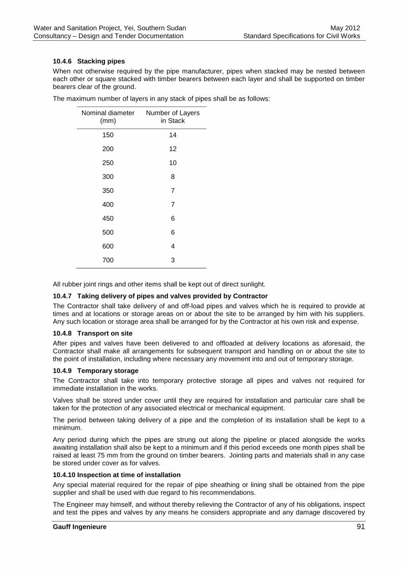
Water and Sanitation Project, Yei, Southern Sudan May 2012 Consultancy – Design and Tender Documentation Standard Specifications for Civil Works
Gauff Ingenieure 91
10.4.6 Stacking pipes When not otherwise required by the pipe manufacturer, pipes when stacked may be nested between each other or square stacked with timber bearers between each layer and shall be supported on timber bearers clear of the ground.
The maximum number of layers in any stack of pipes shall be as follows:
Nominal diameter (mm)
Number of Layers in Stack
150 14
200 12
250 10
300 8
350 7
400 7
450 6
500 6
600 4
700 3
All rubber joint rings and other items shall be kept out of direct sunlight.
10.4.7 Taking delivery of pipes and valves provided by Contractor The Contractor shall take delivery of and off-load pipes and valves which he is required to provide at times and at locations or storage areas on or about the site to be arranged by him with his suppliers. Any such location or storage area shall be arranged for by the Contractor at his own risk and expense.
10.4.8 Transport on site After pipes and valves have been delivered to and offloaded at delivery locations as aforesaid, the Contractor shall make all arrangements for subsequent transport and handling on or about the site to the point of installation, including where necessary any movement into and out of temporary storage.
10.4.9 Temporary storage The Contractor shall take into temporary protective storage all pipes and valves not required for immediate installation in the works.
Valves shall be stored under cover until they are required for installation and particular care shall be taken for the protection of any associated electrical or mechanical equipment.
The period between taking delivery of a pipe and the completion of its installation shall be kept to a minimum.
Any period during which the pipes are strung out along the pipeline or placed alongside the works awaiting installation shall also be kept to a minimum and if this period exceeds one month pipes shall be raised at least 75 mm from the ground on timber bearers. Jointing parts and materials shall in any case be stored under cover as for valves.
10.4.10 Inspection at time of installation Any special material required for the repair of pipe sheathing or lining shall be obtained from the pipe supplier and shall be used with due regard to his recommendations.
The Engineer may himself, and without thereby relieving the Contractor of any of his obligations, inspect and test the pipes and valves by any means he considers appropriate and any damage discovered by
Water and Sanitation Project, Yei, Southern Sudan May 2012 Consultancy – Design and Tender Documentation Standard Specifications for Civil Works
Gauff Ingenieure 92
such inspection shall be repaired by the Contractor as aforesaid.
The Contractor shall remove from the site and shall provide a replacement for any pipe or valve which in the opinion of the Engineer is so badly damaged as to be unfit for repair on the site.
10.5 CUTTING OF PIPES
10.5.1 Ductile iron pipe Any cutting of pipe shall be made by use of cutting tools recommended by the manufacturer and approved by the Engineer. Cutters utilizing compression will not be allowed for cutting ductile iron pipe. All cuts shall be clean and perpendicular to the axis of the pipe. Any damage to the linings shall be repaired.
10.5.2 Steel pipe All field cutting of the pipe shall be minimized. When such cutting is required it shall be done by a suitable cutting machine, leaving a. smooth cut at right angles to the axis of the pipe. Care shall be taken not to damage the coating or lining of the pipe.
10.5.3 Asbestos cement pipe Field cut ends shall be smooth and at right angles to the centreline of the pipe. Tapering of cut ends shall also be made in accordance with the manufacturer's recommendations.
10.5.4 Polyvinyl -chloride pipe Cutting of the pipe shall be kept to a minimum. When cuts are necessary they shall be perpendicular to the axis of the pipe and smooth. Cuts shall be made in accordance with the pipe manufacturer's recommendations. Cut ends shall then be tapered and the bevelled end shall be exactly the same as the spigot end of the pipe as manufactured at the factory.
Solvent welds which are only allowed for service connections shall be made in strict accordance with the manufacturer's recommendations and utilize only solvents furnished by the manufacturer. In addition, it will be necessary to install underground piping so that the offset from true horizontal alignment is not more than 30 cm in 30 metres of the laying length. Care shall be taken to ensure that the temperature of both sections of pipe being joined are the same.
10.5.5 Closing lengths Pipes which are required to be cut to form closing pieces in any portion of the pipeline or to terminate in manholes or other parts of the works shall not be cut until after all adjacent pipes have been installed and jointed.
The Contractor shall determine the length of each closing piece and the required angle and shape of the cut. The cut shall be neatly performed and the end of the pipe shaped up and trimmed so as to ensure an accurate joint or termination as the case may be. Any damage to sheathing coating or lining shall be made good.
The unused part of any cut pipe shall be the property of the Contractor and shall be disposed of by him off the site unless with the Engineer's approval it can be used elsewhere in the works.
10.6 INSTALLATION OF PIPES - GENERALLY
Unless specified otherwise pipes shall be installed singly and shall be jointed at the time of installation or afterwards if appropriate.
The pipes shall be accurately installed to the lines, levels, grades and positions set out by the Contractor. Changes in direction or in grade of the pipeline shall be carried out by making use of any permissible deflection of joints between straight pipes or by the introduction of special bends as may be directed by the Engineer.
10.7 INSTALLATION OF PIPES UNDERGROUND
10.7.1 Lowering of pipes into trench Proper instruments, tools and facilities satisfactory to the Engineer shall be provided and used by the Contractor for the safe and convenient performance of the work. All pipes, fittings, and valves shall be carefully lowered into the trench piece by piece by means of derrick, rope, or other suitable tools or

Water and Sanitation Project, Yei, Southern Sudan May 2012 Consultancy – Design and Tender Documentation Standard Specifications for Civil Works
Gauff Ingenieure 93
equipment, in such a manner as to prevent damage to pipes, valves, fittings, etc., and protective coatings and linings. Under no circumstances shall materials be dropped or dumped into the trench. If damage occurs to any pipe, fitting, valve or accessory in handling, the damage shall be immediately brought to the Engineer's attention. The Engineer shall prescribe corrective repairs or rejection of the damaged items.
10.7.2 Cleaning of pipes and fittings All lumps, blisters, and excess and fittings coating shall be removed from the socket and spigot end of each pipe. The outside of the spigot end and the inside of the socket shall be wiped clean, dry and free from oil and grease before the pipe is laid.
10.7.3 Laying of pipes Every precaution shall be taken to prevent foreign material from entering the pipe while it is being placed in the line. During laying operations no debris, tools, clothing or other materials shall be placed in the pipe.
As each length of pipe is placed in the trench, the spigot end shall be centred in the socket and the pipe forced home and brought to correct line and grade.
The pipe shall be secured in place with approved backfill material tamped under it except at the sockets. Precautions shall be taken to prevent dirt from entering the joint space.
At times when pipe laying is not in progress, the open ends of pipe shall be closed by a means approved by the Engineer.
10.7.4 Coordination with excavation The construction of the pipeline in trenches shall be coordinated with the excavation and refilling of trenches so as to ensure expeditious completion of the whole operation.
10.7.5 Socket ends Pipe shall be laid with socket ends facing in the direction of laying, unless directed otherwise by the Engineer. Where pipe is laid on a grade of 10 % or greater, the laying shall start at the bottom and shall proceed upward with the socket ends of the pipe upgrade.
10.7.6 Unsuitable conditions No pipe shall be laid when, in the opinion of the Engineer, trench conditions are not suitable.
10.7.7 Pipe insulation Wherever it is necessary to join pipes of dissimilar metals pipe insulation shall be installed as approved by the Engineer.
10.7.8 Buried ductile iron pipes Ductile iron pipelines, where buried, shall be protected with proprietary polyethylene sleeving according to DIN 30674. The sleeving shall be provided by the Contractor.
Before installation of each pipe and fitting the Contractor shall apply the sleeving ensuring that it is correctly positioned relative to the spigot end of spigot and socket pipes, and terminated behind the socket. The sleeving shall be pulled tightly around the barrel of the pipe and any surplus folded over at the crown of the pipe to form a triple thickness layer of film.
Plastic adhesive tape shall be used to secure the folds on the crown of the pipe at least four positions along the length of the pipe, and the ends of the sleeving shall be sealed to the pipe by taping around the whole circumference.
The sleeving at joints, tees and tapers shall be completed by using the sleeving cut to form sheets to wrap around the joints, tees and tapers and secured with the adhesive tape, overlapping onto the sleeving of the adjacent pipe of fitting.
Polyethylene sleeving shall not be applied to those sections of pipelines exposed either above ground or in chambers or to be cased in concrete. At such places the sleeving shall be terminated at a point 500 mm below the surface of the ground or at the external face of the valve chamber structure or the face of the concrete surround, whichever is applicable.

Water and Sanitation Project, Yei, Southern Sudan May 2012 Consultancy – Design and Tender Documentation Standard Specifications for Civil Works
Gauff Ingenieure 94
10.7.9 Bedding to pipes Refer to the General Specification for Earthworks, Part 2.
10.7.10 Concrete bed and surround If necessary, pipes shall be bedded haunched or surrounded in concreted. Concrete shall be unreinforced and shall comply with the requirements of the General Specification for Concrete, except that vibration will not be required. Any formwork required shall be of class F1 to the requirements of the General Specification for Formwork.
Such concrete shall not be placed until the joints at each end of the pipe have been completed. Each pipe shall be supported on at least two purpose made precast concrete blocks, which shall be left in place, and the full width and depth of bedding concrete shall be placed and carefully punned beneath the pipe followed at once by the addition of any haunching and surround concrete. Unformed surfaces shall be of spade finish. The pipe shall be prevented from floating or other movement during concreting.
Where necessary, the continuity of concrete bed haunch or surround to pipe with flexible joints shall be broken at each joint.
10.7.11 Installation of pipes above around Pipes shall be installed above ground where required for river crossing and bridge crossing.
The Contractor shall design, install and furnish all pipe hangers and supports to the approval of the Engineer. The Contractor shall install sleeves or wall casting or all pipes passing through masonry walls and concrete floors or walls and concrete inserts for hangers and supports, in accordance with the appropriate specification as soon as forms are erected and before concrete is in place.
All pipes shall be rigidly supported by approved hangers, inserts, or supports with adequate provisions for expansion and contraction. Pipes shall not be supported from other pipes or from stairs, ladders, or walkways unless specifically directed by the Engineer.
Where pipes are installed on structural steel supports, blocking of pipe shall be provided to avoid lateral pipe movement.
All vertical pipes shall be supported at sufficient intervals by approved pipe collars, clamps, brackets, or wall rests, and at all points necessary to ensure rigid construction.
10.7.12 Installation of service connections Service connections comprise the tapping unit at the main, the subsequent tertiary pipe and the actual service line to the house.
The laying of service connections shall comply in general with the procedure specified previously.
Service pipes shall be laid at sufficient depth to clear any obstructions such as stormwater drains, service ducts, irrigation channels, house connection drains and other underground installations.
Caps shall not be removed from pipe ends until they are ready for jointing.
Pipes shall be laid on firmly compacted beds, so that they rest evenly and uniformly.
The connections shall be pressure-tested by applying the full mains pressure before backfilling the trench.
If pipes are not laid in a separate concrete channel they shall be laid in the trench with a minimum of 750 mm of cover below the surface of the ground. The Contractor shall ensure that no water is allowed to enter the trench, and that no water or extraneous matter enters the pipes during laying.
10.8 INSTALLATION OF VALVES AND FITTINGS
10.8.1 General Valves, fittings, plugs, and caps shall be set and joined to pipes in the manner specified above for cleaning, laying and joining pipes. The Contractor shall furnish all components required for construction of valve chambers and valve control access to buried valves, including cast iron covers.
10.8.2 Air valves Air valves shall be installed at all high points when necessary.
Water and Sanitation Project, Yei, Southern Sudan May 2012 Consultancy – Design and Tender Documentation Standard Specifications for Civil Works
Gauff Ingenieure 95
10.8.3 Washouts Washouts shall be installed complete at all low points where necessary. Washouts shall be formed by a standard T-piece with the drain branch.
The outlet of the drain must be directed to the lowest ground level, in such a way that no wash-aways of the main pipe can occur.
The drain pipe of washouts shall not be connected to any sewer, submerged in any stream, or be installed in any other manner that will permit back-siphoning into the distribution system.
If drainage by gravity is not possible the Contractor shall consider the installation of sufficient drainage pits including complete pumping equipment.
10.8.4 Fire hydrants Underground fire hydrants shall not be installed with their tops deeper than 450 mm below the surface. If the pipe is laid in such a way that the hydrant would be positioned deeper than 450 mm1 the vertical pipe to the fire hydrant T-piece must be extended by a flanged pipe section.
The vertical pipe section to standpost hydrant shall be of sufficient length to allow the prescribed position of the hydrant above ground. All extension pipes must be cut and welded.
10.8.5 Isolation valves Isolation valves shall be installed as shown on the approved drawings. Special attention shall be drawn to clean and careful installation of valves. Any foreign matter resting in valve-seats shall be removed to ensure efficient operation of valves.
All isolation valves shall be installed on concrete bases and joined with dismantling pieces. The top of the operating stem shall not be deeper than 600 mm below the surface, otherwise the stem shall be extended.
10.8.6 Bends and fittings Pipelines shall be laid in straight lines with gradual changes being taken up at the joints as approved by the manufacturer. Where a sudden change of direction cannot be avoided, bends shall be used. The location of bends, tees, and other fittings shall be determined in the field in close cooperation with the Engineer.
10.8.7 Blind ends All pipe ends that shall be connected to future extensions plugs, caps or blind flanges shall be installed and secured in place.
10.8.8 Valve chambers and similar structures The surface valve box shall not transmit shock or stress to the valve and shall be centred and plumb over the operating nut of the valve. The lid of the box shall be flush with the surface of the finished pavement or such other level as directed by the Engineer.
Valve chambers shall be constructed of reinforced concrete. A precast concrete chamber may be installed upon the Engineer's approval.
Cover frames shall be set in cement mortar. The construction of a valve chamber shall include the supply and installation of step irons, which shall be installed in all manholes deeper than 0.6 m. They shall be spaced 0.3 m in a vertical directions and 0.2 m in a horizontal direction.
The valve nut shall be readily accessible for operation through the opening of the manhole or the surface box, which shall be set 0.3 m higher than the adjacent surface of the finished pavement.
Valves, which will be installed in the ground, shall be provided with extension spindles and protection tubes up to the surface box.
10.8.9 Anchor blocks All movement of the pipeline shall be prevented by concrete anchor blocks. The Contractor shall design, supply and construct all necessary anchor blocks. Anchor blocks shall be provided for all branches, caps, tapers, bends, reducers, valves, hydrants, etc., and shall be placed in such a manner to allow easy access for removal of valves, hydrants, fittings, etc. The quality of concrete shall be of class B 25 and reinforced anchor blocks shall be of class B 25.

Water and Sanitation Project, Yei, Southern Sudan May 2012 Consultancy – Design and Tender Documentation Standard Specifications for Civil Works
Gauff Ingenieure 96
Thrust forces, calculation and sizing of anchor blocks shall be taken from the manufacturer's instructions for a particular pipe material; pipe pressure for calculation purposes shall be the field test pressure.
Thrust blocks shall be cast between the fitting which is to be supported and the undistributed wall of the trench. The concrete shall be placed around the fitting in such a way that the couplings are not covered or fixed by it to allow for flexibility and to provide access to the collars for replacing when necessary.
Before casting concrete, bituminous felt shall be wrapped around the fittings at the interfere between concrete and the fitting. Where required, anchor clamps shall be cast into the anchor blocks.
10.8.10 Concrete protection Pipelines running under drain channels, streams or roads shall be encased in concrete class B 25 in full length, if not otherwise prescribed. Before the concrete is placed, the pipe and all fittings shall receive a double wrapping of bituminous felt. The minimum thickness of the concrete encasement around the pipeline shall be one quarter of the pipe diameter, but at least 15 cm. The concrete shall be reinforced by steel bars as calculated by the Contractor and approved by the Engineer.
Where pipelines cross over drains or other utilities, and where the soil cover is not sufficient and a concrete encasing is not advisable, a reinforced concrete slab shall be placed 100 mm above the top of the pipe. This lead spreader slab shall be 100 mm thick with a width 3 times the outside diameter of the pipe. The slab may not be cast before the backfilled ground has been compacted. Concrete shall be of class B 25.
10.8.11 Railway crossings Where the pipeline crosses any railway, it shall be installed in accordance with the requirements of the related authorities.
The Contractor shall be responsible for coordinating this work with the National Railway Company and other related authorities.
10.8.12 Metal tape Non-metallic pipes shall be laid with a continuous metallic tape for simple detection after installation. The tape (or wire) shall be or corrosion resistant metal and shall be placed on top of the pipe.
10.9 TESTING, DISINFECTION AND RINSING
10.9.1 General All pipelines and all works shall be subject to pressure and leakage tests after being laid and installed before commissioning.
Pressure and leakage tests will be carried out simultaneously.
10.9.2 Testing The test shall be performed in accordance with DIN 4279.
Where lines cannot be tested under pressure in a single operation, they shall be tested in sections (section test). The length of the sections shall be at the discretion of the Contractor subject to approval by the Engineer.
The results of the tests, specifying the layout of sections of system, pipes and fittings tested including all relevant data of testing as weather, time, duration, filling time, pressure, etc., shall be produced in form of a report by the Contractor to be approved by the Engineer.
This report shall not relieve the Contractor of his responsibility of care and maintenance of the system until the date of the Maintenance Certificate.
10.9.3 Cleaning out after testing After the completed pipeline is tested, approved and backfilled and the Contractor has removed all temporary works and has reconnected any parts temporarily removed from the pipeline, the Contractor shall finally clean out the whole pipeline and flush it through with water.
The Contractor shall be liable to the Employer for any damage caused to the pipeline or to pumps and other equipment of the Employer as a result of foreign matter of any kind not having been cleaned out of the pipeline before it is handed over to the Employer.
Water and Sanitation Project, Yei, Southern Sudan May 2012 Consultancy – Design and Tender Documentation Standard Specifications for Civil Works
Gauff Ingenieure 97
10.9.4 Disinfection After cleaning out, a disinfection shall be performed in the following manner: after flushing the pipes the system shall be drained completely, all valves shall be closed carefully and the system filled with a strong chlorine solution of about 50 ppm free chlorine. This solution shall remain in the system for at least 24 hours uninterruptedly and still show a chlorine content of at least 25 ppm. After draining the solution the system shall be rinsed with potable water with a free chlorine content of 2 to 4 ppm as ordered by the Engineer which is to be tested at the inlet by an orthotolidine reagent with a colour scale. After 24 hours, water samples taken at any outlet of the pipeline shall show the same chlorine content as charged. This proves adequate disinfection and rinsing. In case of failure of the test, chlorination and rinsing shall be repeated until fulfilment of the requirements.
After completion of disinfection and rinsing the Contractor's results shall be reported by the Contractor in writing and signed by the Contractor and the Engineer.
The Contractor shall provide at his own expense such sampling points as the Engineer may direct if permanent points are not available or suitably located.
10.9.5 Water for testing and cleaning The Contractor shall provide all water required for testing and cleaning the pipeline, and shall use only potable water.
10.10 MARKERS
Markers for pipelines, valves and hydrants shall be made out of concrete class B 25 prefabricated with the following dimensions: 30/140/10 cm with chamfered corners and placed in a concrete bed of 50/50/50 cm so that the marker protrudes 90 cm.
Figures and letters shall recess about 8 to 10 mm from the surface and give the following information for pipelines: reference of line, diameter, progressive distance; for valves: number of valve and offset; for hydrants: number of hydrant and offset.
11 SITEWORKS
11.1 SCOPE
The works to be carried out under this chapter comprise various site works as roads and pavements, surface drainage, planting of lawn, shrubs and trees, erection of fences with gates, construction of septic tank with soak-away.
11.2 MASS EARTHWORKS
Not used.
11.3 ROADS, PAVEMENTS AND SURFACE DRAINAGE
11.3.1 Design of roads The structural design for pavements and roads shall correspond to the road category "D V" in accordance with ‘RAS-N’ (Richtlinie fjjr die Anlage von Straßen -Netzfunktion) or equivalent.
Roads and paved areas shall be laid out to plans prepared by the Contractor and approved by the Engineer. The plans shall make proper and adequate allowance for road curvatures, crossfalls, parking spaces and turning room both for passenger vehicles and, where appropriate, for goods vehicles.
Upstanding kerbs shall be provided against footpaths and where it is essential to keep traffic from road verges which contain buried services, which are landscaped or which are close to buildings. Elsewhere kerbs shall be flush with the pavement surface.
11.3.2 Design of drainage Not used.
11.3.3 Precast concrete kerbs and flags Precast concrete kerbs shall comply with DIN 483.

Water and Sanitation Project, Yei, Southern Sudan May 2012 Consultancy – Design and Tender Documentation Standard Specifications for Civil Works
Gauff Ingenieure 98
11.3.4 Pipes and fittings Concrete cylindrical pipes and fittings shall be "standard" quality with approved flexible spigot and socket or ogee joints and shall comply with DIN 4032 or equivalent.
Glazed vitrified clay pipes and fittings shall conform to DIN 1230 or their equivalent. These pipes shall not be used for diameters greater than 300 mm.
Pipes for porous drainage shall be of PVC to DIN 4925.
11.3.5 Manholes chambers and gullies Manholes, inspection chambers and gullies shall be constructed to details shown in the standards. Where precast they shall comply with DIN 4034 or DIN 4052 or equivalent.
Cast iron covers or gully gratings shall comply with DIN 4290 or DIN 4052.
11.4 ROADS AND PAVEMENTS
11.4.1 General Roads and pavements, as specified hereunder, shall include the construction of all roads and pavements to line and levels as shown on the approved drawings. In this work "earthworks" as specified under "General Specification - Earthworks", are not included.
Materials shall be new and shall comply with standard quality and dimension provisions.
For unstandardized materials and building components the Contractor shall, on demand, supply samples and name of manufacturer, and shall be subject to approval by the Engineer.
Mineral materials shall be weatherproof, of adequate hardness, watertight and of sufficient adhesion to bind. They may not contain any swelling, weathering, loamy, clay or organic components in harmful quantities.
Bituminous mixes must be blended so as to be suitable for the purpose of application. Special consideration shall be given to climatic and location conditions, volume and type of traffic.
11.4.2 Formation and subgrade Formation means the surface of the soil in cut or fill after completion of earthworks on which further roadwork construction is to be carried out.
Subgrade means the soil immediately below the formation.
The formation and subgrade shall be graded and compacted to the levels, falls, cambers and densities as required in RSTO 86 (Richtlinien für Standardisierten Oberbau).
The subgrade shall be compacted in accordance with ZTVE-StB 76. As a minimum it shall be so compacted that the dry density of the upper 150 mm of the ground or fill is not less than 95 % of the maximum dry density determined by tests in accordance with DIN 18127.
Where the subgrade is in natural ground the compaction shall, whenever possible, be carried out at or near the natural moisture content of the ground.
Any irregularities or depressions that develop in the formation during compaction of the subgrade shall be corrected by loosening the surface of these places and adding, removing or replacing materials and re-compacting so that the surface is smooth and uniform.
Any area of subgrade that shall become muddy, broken up or loosened due to weather conditions or otherwise damaged shall be corrected or prepared again by the Contractor as specified above.
Where existing ground conditions are such that direct compaction of the subgrade cannot be carried out as specified, unsuitable material shall be removed and replaced with granular sub-base.
The formation shall be kept free of standing water at all times and drains shall be provided so that it will drain quickly and effectively during rain.
On completion of compaction and before commencing the next operation, the surface of the subgrade shall comply with the surface tolerances specified in ZTVE-StB 78 or ZTVV-StB 81.

Water and Sanitation Project, Yei, Southern Sudan May 2012 Consultancy – Design and Tender Documentation Standard Specifications for Civil Works
Gauff Ingenieure 99
11.4.3 Sub-base and roadbase The sub-base and roadbase shall be graded and compacted to the levels, falls, cambers and densities as required in RSTO-86 or as shown on the approved drawings.
Material for the sub-base and roadbase shall be laid in one or more layers, each not exceeding 150 mm thick nor being less than 75 mm, and the total compacted thickness of sub-base and roadbase shall nowhere be less than the specified nominal thickness.
The sub-base and roadbase materials shall be deposited in such a manner that there is no segregation and the material requires the minimum of blading or spreading.
Each layer of material shall be compacted immediately after spreading in accordance to ZTVE-StB 78.
If any of the subgrade material is worked into the sub-base material during the spreading, blading or compaction, all the sub-base material in the affected area shall be removed and replaced with fresh sub-base material.
Upon completion of compaction and before commencing the next operation, the surface of the granular subbase and roadbase shall comply with the surface tolerances specified in ZTVT-StB 86 or ZTV bit-StB 84.
11.4.4 Sealing Wherever possible, of final trimming of the formation, compaction of the subgrade, and placing and compaction of the granular sub-base and roadbase shall be carried out without intermediate delays.
The Contractor shall be responsible for taking all necessary steps to prevent damage to the previously completed layer or layers by excessive wetting or drying due to weather conditions or by traffic or any other cause. If the Contractor considers it advisable or if so ordered by the Engineer, the completed layers shall be sealed using bitumen road emulsions in accordance with RSTO-86 and TV-bit.
In any case, the completed surface of the roadbase shall be sealed as specified above immediately it has been completed and checked for compliance with the specified tolerances.
11.4.5 Surface dressing Where the Contractor proposes to use any completed layer of road construction for any significant amount of traffic, other than that required for the construction of succeeding layers, he shall first obtain the approval of the Engineer, who may direct which areas shall be surface dressed.
In this case the layer shall be surface dressed in accordance with RSTO-86 and TV-bit using bitumen road emulsion and chippings.
The Contractor shall in any case be responsible for making good any damage to the completed layers caused by his own construction traffic whether surface dressing as specified has been carried out in accordance with the Engineer's directions or not.
11.4.6 Flexible road surfacing Unless otherwise specified or detailed, material for flexible road surfacing shall be coated macadam, in a quality corresponding to TV-bit.
The surface on which each course of coated macadam is to be laid shall be free from standing water and any loose or deleterious material and shall be tested for accuracy.
Before laying commences in any area, a tack coat of bitumen road emulsion shall be applied to the whole area of the preceding course, and also to kerbs and other concrete surfaces, manhole covers and gully grating frames, and any other surfaces with which the coated macadam will be in contact, including the edges of previously laid strips of coated macadam. The emulsion shall be allowed to break completely before the coated macadam is laid on it.
The compacted thicknesses of individual layers shall be not less than the minimum compacted thicknesses specified or shown on the approved drawings.
11.4.7 Delivery of coated macadam Coated macadam materials shall be delivered to site in clean vehicles and shall be protected to minimize loss of heat in transit and contamination by dust or other deleterious matter. The use of dust, oil or water on the interior of the vehicles to facilitate discharge is permissible, but the amount shall be
Water and Sanitation Project, Yei, Southern Sudan May 2012 Consultancy – Design and Tender Documentation Standard Specifications for Civil Works
Gauff Ingenieure 100
kept to a minimum, and all necessary steps shall be taken to ensure that any excess is removed by tipping or brushing. The rate of delivery to the site shall be regulated so as to enable the material to be laid with the minimum of delay and so that the paver can operate continuously.
11.4.8 Concrete paved areas Concrete paved areas shall be constructed in accordance with RStO-86 and ZTV Beton 78 and with the relevant requirements of the "General Specification for Concrete, Reinforcement and Formwork".
Concrete for roads and pavements shall be of class B 25. The use of additives shall be subject to the approval of the Engineer. Concrete courses shall be never less than 100 mm thick.
If reinforcement is required, it shall be achieved with reinforcement steel mesh of at least 2 kg/m2, unless otherwise approved. The reinforcement shall not influence the effectiveness of the joints. The concrete cover shall be at least 30 mm thick.
Transport and placing of the concrete shall be coordinated so that the concrete can be completely placed prior to setting.
The strength of the concrete and the properties of the concrete surface shall not be influenced by the execution of joints. The joints shall be made early enough so that no cracks appear.
Expansion joints shall be executed at the required intervals and shall enable expansion of the plates and be fixed. The expansion joints shall be 20 mm wide.
Dummy joints are to be executed by cutting a groove with a depth of at least 25 % of the concrete surface in the set concrete.
In the case of butt joints, the set concrete side surface shall have a simple cold bituminous course.
The upper part of expansion and dummy joints is to be poured to the edges with bituminous joint sealer. Prior to placement of the bituminous joint sealer the joint surfaces shall be dry and clean.
If dowels are required for transmission of transverse forces and protection of the height of the plates, they shall be laid in the middle of the plate thickness and in the inclination of the concrete surface so that they do not obstruct expansion of the plates. Dowels of reinforcement steel with the diameter of 25 mm and a length of 50 cm shall be used.
The distance between dowels shall be uniform and not exceed 30 cm.
In the case of the expansion joints a lead or PVC-sleeve shall be stuck on to the end of each painted dowel half, leaving an expansion facility of 15 mm. Dummy joints and butt joints do not require sleeves.
The concrete shall be protected against harmful influences until correct setting, i.e. against permanent drying out, especially due to sun and wind, against washing out due to rain, against heating or quick cooling. The concrete surface shall be kept moist for 7 days or protected from drying out.
11.4.9 Kerbs Precast concrete kerbs shall be laid true to line and level and any kerb found to be more than 3 mm out of line or level at either end shall be lifted and re-laid.
Kerbs shall be bedded on a layer of 3:1 sand:cement mortar minimum 10 cm thick on a grade B 10 concrete foundation and shall be backed with concrete shaped up to the required cross-section.
Specially cast circular kerbs shall be used on curves of 15 m radius or less.
Kerbs shall be jointed with cement mortar except at expansion joints, which shall be made with preformed joint filler 10 mm thick.
11.4.10 Gravel roads Normally the construction of gravel roads will not be permitted, except if the construction is approved by the Engineer.
The material for gravel roads shall be a natural or crushed well-graded gravel with a maximum grading of stone size of 32 mm.
Preparation of the subgrade shall be as specified previously.
The thickness of the compacted gravel bed shall be not less than 150 mm for roads with vehicular traffic
Water and Sanitation Project, Yei, Southern Sudan May 2012 Consultancy – Design and Tender Documentation Standard Specifications for Civil Works
Gauff Ingenieure 101
or in other cases 100 mm.
The material for gravel roads shall be approved by the Engineer.
11.4.11 Footpaths Footpaths shall be surfaced with either precast concrete flags minimum size 0.3 x 0.3 m or with coated macadam.
The base for footpaths shall be formed from flexible surfacing, laid and compacted to a minimum thickness of 75 mm using a roller of at least 2.5 tonnes mass or other approved equipment giving equivalent compaction.
Precast concrete flags shall be bedded on a layer of sand approximately 50 mm thick tamped into place.
Where footpaths have coated macadam surfacing, the construction shall be as follows: precast concrete edging in accordance with DIN 482 shall be bedded and backed with in-situ concrete. The base for the footpath shall be constructed as specified above and shall then be sealed. Surfacing shall consist of a single course of coated macadam flexible surfacing laid and compacted to a minimum thickness of 25 mm.
Concrete footpaths shall be made of concrete B 25 with a mortar topping, constructed on a prepared bed as specified above. Concrete footpaths shall be constructed in accordance to the “General Specification for Concrete, Reinforcement and Formwork".
11.4.12 Reinstatement of existing roads and footpat hs Nor used.
11.5 SURFACE DRAINAGE
11.5.1 General Surface water shall be discharged or disposed safely at position where it does not endanger any structures, roads, crop fields and private property.
Trenching for drainage pipework and excavation for manholes, gullies and the like shall be as specified in the "General Specification - Earthworks".
11.5.2 Drainage work Pipework, manholes and gullies shall be built and backfilled as specified before drainage is tested for watertightness.
Open channels shall be constructed either as earth channels, in stone work or with precast concrete units in half-round sections or trapezoidal section.
Open channels adjacent to buildings, basins and other structures and channels with longitudinal slopes steeper than 1:100, depending on the soil conditions, shall be constructed with precast concrete or stone work. Channel sections, which are subject to scouring, shall be protected with stone pitching.
Precast concrete channels shall be manufactured from concrete class B 25. Installation of precast concrete channels shall be to the method specified in the "General Specification of Pipelines”.
All backfilling shall be with selected excavated material approved by the Engineer.
If the soil is unsuitable for laying of channels, the Contractor shall place a bedding layer of approved granular material or concrete B 10 under the channel.
All road crossings of channels shall be constructed such that vehicular traffic is not exposed to danger, installation of pipes or culverts, or shall provide gratings over the channel.
11.6 FENCING AND GATES
11.6.1 General The works comprise the supply and erection of fences and gates both around the perimeter of the site and internal fencing.
Internal fencing shall be of the standard type and fencing around the perimeter of the site shall be of the

Water and Sanitation Project, Yei, Southern Sudan May 2012 Consultancy – Design and Tender Documentation Standard Specifications for Civil Works
Gauff Ingenieure 102
security type. Security fences shall be anti-intruder type.
All items of material for fences and gates shall be standard products of manufacturers regularly engaged in the production of the type of fence specified herein.
Posts and struts shall be either reinforced concrete or galvanized steel sections. Timber posts shall not be used.
All wire shall be galvanized wire with plastic coating. The length of the sides of the chain link mesh shall be 50 mm. All chain link fencing shall be barbed along the top edge.
The work pertaining to fencing shall consist of providing all necessary materials and constructing the fencing including all requisite materials, unloading and storage on site as well as any intermediate handling required. All earth, backfilling and concrete work shall be included in the offer. All posts and struts shall be anchored in rigid concrete B 25 foundations of sufficient depth. In the vicinity of gates, structures and fence openings, adequate provision to fix the fences shall be provided. The distance of the bottom of the wire mesh to the levelled ground surface shall not exceed 2.5 m.
11.6.2 Standard fencing Standard fencing shall consist of a 1.0 m high mesh wire fencing with steep posts of circular tubing or other cross sections of high tensile steel as approved by the Engineer. Posts shall be galvanized inside and outside and plastic coated and closed at the top with plastic or cast zinc alloy caps.
End, intermediate, corner and straining posts shall be 1.5 m long, the gate post 1.5 m long. The distance between posts shall be approximately 2.5 - 3.0 m.
Posts are to be set in sufficient B 25 concrete foundations.
Intermediate straining posts are to be installed to 50 m intervals. The intermediate post shall have two diagonal struts and shall be provided with 3 double ratchet winders for the strain line wires and one joint clamp to fix the struts to the post. Strut foundations shall be cast in concrete B 25 and in sufficient size.
Corner and end posts shall either be supported by struts as for intermediate straining posts or by a horizontal bracing. Sufficient straining wires, winding ratchets, jointing clamps and other required fittings shall be provided for all end, corner and gate posts.
Three rows of straining wires are to be installed for the 1 m high fence.
11.6.3 Security fencing Security fencing shall be constructed as described for standard fencing, but with posts provided with barbed wire holders inclined inwards.
The total fence height shall be 2.5 m. Post length shall be 3.5 m minimum. Three rows of galvanized and plastic coated 2 strand, 4 point barbed wire shall be fixed to the cranked top section of the post. Sufficient ratches, winders and clips are to be provided to assemble and to secure the barbed wire.
11.6.4 Gates The tops of the gate frames shall be levelled with the tops of adjacent fencing.
Gates in fencing with barbed wire on extension arms shall also carry wire mounted on extension arms as specified.
All gates shall be of welded steel construction, galvanized and painted and covered with plastic coated chain link mesh and surmounted with galvanized, plastic coated barbed wire to match the fencing. Sliding gates shall be provided with roller support tracks
Gates shall be complete with all fittings such as drop bolts, back catches, locking bars, lock plates and locks, etc., including two keys per lock.
11.6.5 Installation Fences shall be installed in accordance with the fence manufacturer’s drawings and written installation instructions, except as modified herein. Each line of fencing shall be erected so that it is plumb, taut, true to line and grade, and complete in all detail. The outside face of the fabric shall be on the property line where the fence runs along the property boundary.
Straining posts shall be installed at points where the slope of the ground and fence change by 20 degrees or more.
Water and Sanitation Project, Yei, Southern Sudan May 2012 Consultancy – Design and Tender Documentation Standard Specifications for Civil Works
Gauff Ingenieure 103
Straining posts shall also be installed at changes in line where the angle of deflection is 10 degrees or more.
Posts shall be suitably braced during concreting to ensure that they remain in the correct line and level during placing of concrete and the concrete shall be cured for 3 days before any further work is done on the posts.
11.7 TESTS AND INSPECTION - GENERALLY
The Contractor shall, prior to execution, ascertain and upon request of the Engineer, prove that the materials and components used are suitable for the intended application.
The Contractor shall during execution ascertain and shall upon request of the Engineer, prove that the materials and components used correspond to the contractual requirements.
The Contractor's responsibility will not be released even if control tests have been performed by the Engineer.
Sealed joint drains shall be tested in sections by water under a head of not less than 1 m to the Engi-neer's approval. Drains shall not leak under this pressure
Soakaways, where provided, shall be tested by subjecting them to an overflow equivalent in volume to the design rainfall intensity for a time of 15 minutes on the area draining to the soakaway. The soakaway shall not back up during the test.
11.8 CONCRETE REPAIR AND REFURBISHMENT
11.8.1 Scope This specification covers the requirements for the works necessary to repair and refurbish existing concrete units, using normal concrete, cement based shot Crete as replacement for removed concrete sections, crack-overbridging polymer modified protective coatings, and crack injection with synthetic resin.
All works using normal concrete shall comply to part 5.3 of the general Specification, but the maximum aggregate size shall be limited to 8mm if the layer thickness is less than 5cm and 16mm If the layer thickness is equal or more than 5cm.
Shotcrete shall be concrete B II according to DIN 18551. With respect to the maximum aggregate size the same as for concrete shall apply.
11.8.2 Personnel The Contractor’s personnel in charge of concrete repair and refurbishment shall be well-experienced and well-qualified in this field of work. The foreman and the leading hands shall have had previous experience in this field.
The Contractor shall prior to the Commencement Date submit to the Engineer appropriate certificates and documents verifying the experience of the personnel.
Upon the request of the Engineer, the Contractor shall remove from the works all personnel which appear inexperienced in opinion of the Engineer.
11.8.3 Equipment The site shall be equipped in such a manner as to be able to fulfill all the requirements of the Specification. The site shall be equipped with workshops and all the equipment and minor material necessary to carry out the work.
11.8.4 Clearing of rubbish etc. and cleaning of str uctures Before commencement of any repair or refurbishment at any structure, the Contractor shall clear away all rubbish from inside and outside the structure. Furthermore the Contractor shall pre-clean the entire structure (all surfaces, walls, ceilings, floors, stairs, posts, beams etc.) Using high pressure water jets. Where the conditions do not allow for the use of high pressure water jets ( e.g. due to electrical installation to be kept alive to allow continued production) the Contractor shall use brooms and steel wire brushes.
All rubbish shall become the property of the Contractor and shall be disposed of off site at locations to
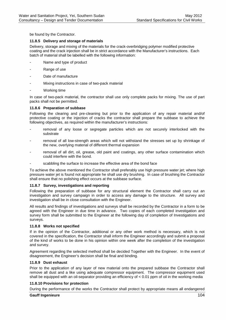
Water and Sanitation Project, Yei, Southern Sudan May 2012 Consultancy – Design and Tender Documentation Standard Specifications for Civil Works
Gauff Ingenieure 104
be found by the Contractor.
11.8.5 Delivery and storage of materials Delivery, storage and mixing of the materials for the crack-overbridging polymer modified protective coating and the crack injection shall be in strict accordance with the Manufacturer’s instructions. Each batch of material shall be labelled with the following information:
- Name and type of product
- Range of use
- Date of manufacture
- Mixing instructions in case of two-pack material
- Working time
In case of two-pack material, the contractor shall use only complete packs for mixing. The use of part packs shall not be permitted.
11.8.6 Preparation of subbase Following the clearing and pre-cleaning but prior to the application of any repair material and/of protective coating or the injection of cracks the contractor shall prepare the subbase to achieve the following objectives, as required within the manufacturer’s instructions:
- removal of any loose or segregate particles which are not securely interlocked with the substrate
- removal of all low-strength areas which will not withstand the stresses set up by shrinkage of the new, overlying material of different thermal expansion
- removal of all dirt, oil, grease, old paint and coatings, any other surface contamination which could interfere with the bond.
- scabbling the surface to increase the effective area of the bond face
To achieve the above mentioned the Contractor shall preferably use high pressure water jet; where high pressure water jet is found not appropriate he shall use dry brushing. In case of brushing the Contractor shall ensure that no polishing effect occurs at the subbase surface.
11.8.7 Survey, investigations and reporting Following the preparation of subbase for any structural element the Contractor shall carry out an investigation and survey campaign in order to access any damage to the structure. All survey and investigation shall be in close consultation with the Engineer.
All results and findings of investigations and surveys shall be recorded by the Contractor in a form to be agreed with the Engineer in due time in advance. Two copies of each completed investigation and survey form shall be submitted to the Engineer at the following day of completion of Investigations and surveys.
11.8.8 Works not specified If in the opinion of the Contractor, additional or any other work method is necessary, which is not covered in the specification, the Contractor shall inform the Engineer accordingly and submit a proposal of the kind of works to be done in his opinion within one week after the completion of the investigation and survey.
Agreement regarding the selected method shall be decided Together with the Engineer. In the event of disagreement, the Engineer’s decision shall be final and binding.
11.8.9 Dust exhaust Prior to the application of any layer of new material onto the prepared subbase the Contractor shall remove all dust and a like using adequate compressor equipment. The compressor equipment used shall be equipped with an oil-separator providing an efficiency of < 0.01 ppm of oil in the working media
11.8.10 Provisions for protection During the performance of the works the Contractor shall protect by appropriate means all endangered

Water and Sanitation Project, Yei, Southern Sudan May 2012 Consultancy – Design and Tender Documentation Standard Specifications for Civil Works
Gauff Ingenieure 105
structural parts as well as all mechanical and electrical equipment which shall either be used in the future or is currently in use or operation. All protection work shall be to the satisfaction of the Engineer.
Any damage to finished work as well as to mechanical or electrical equipment due to insufficient provision of protection shall be made good by the contractor at his own expense. If satisfactory repair of any damage is not possible in the opinion of the Engineer, the Contractor shall arrange for replacement of the entire work and/or equipment.
11.8.11 Waste If not otherwise specified elsewhere all rubbish and waste material shall become the property of the Contractor. All waste shall be disposed of off site at locations to be found by the Contractor.
11.8.12 Drainage In case of any water jetting or similar techniques the Contractor shall provide appropriate drainage to the satisfaction of the Engineer. Submerging of any parts of the structures or surrounding areas due to insufficient drainage shall not be permitted.
Any damage on finished work as well as on mechanical or electrical equipment due to insufficient drainage shall be made good by the Contractor at his own expense. If satisfactory repair of any damage is not possible in the opinion of the engineer, the Contractor shall arrange for replacement of the entire work and/or equipment.
The Contractor shall provide all installations and measures necessary to clean water used during the performance of work to the required quality before discharging to any watercourse.
11.8.13 Protective coating system Following the subbase preparation, the dust exhaust and any crack injection if required, the Contractor shall apply a protective coating which shall consist at least of the following:
- cement based leveling mortar of in average 3mm thickness, in case a 3mm coat will not fill and level surface as agreed with the Engineer shall be applied; the adhesive strength shall be ≥. 3N/mm2
- two layers of cement based polymer modified crack-overbridging protective coating of a minimum thickness of 2000^m, the adhesive strength shall be > 0.8N/mm2
For the protective coating the Contractor shall use only one manufacturer’s complete system. The system shall be applied in strict accordance to the manufacturer’s instructions and recommendations. The manufacturer’s specifications, pamphlets and certificates for the system to be used shall be submitted to the Engineer with the tender. All tendered systems are subject to the Engineer’s approval. The proposed systems tendered must be equivalent to what is described in this specification or better. In any event, deviation from this specification shall be described and established in detail in the tender.
The system of protective coating shall fulfil the following individual Requirements:
- Strong homogenous bond between the subbase and the coating system
- thermal expansion coefficient shall be similar to the original concrete
- vapor diffusion resistance shall be similar to the original concrete
- high resistance to carbon dioxide, sulphate and chlorine ion diffusion
- the materials used shall be certified suitable in contact with potable water, even when permanently submerged
- the top coat of the system shall provide a coloring, complying to RAL 7023 or similar (concrete-gray)
11.8.14 Crack injection, general Unless expressively required otherwise by the Engineer cracks with a crack width of less than 0.2mm shall not be subject of crack injection.
Cracks with a crack width of 0.2mm, water diffused cracks and deep penetrating cracks shall be filled with epoxy resin. The epoxy resin shall be a two component material, shall be cold hardening and solvent free.
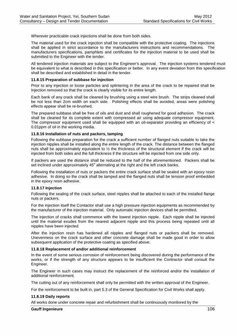
Water and Sanitation Project, Yei, Southern Sudan May 2012 Consultancy – Design and Tender Documentation Standard Specifications for Civil Works
Gauff Ingenieure 106
Wherever practicable crack injections shall be done from both sides.
The material used for the crack injection shall be compatible with the protective coating. The injections shall be applied in strict accordance to the manufacturers instructions and recommendations. The manufacturers specifications, pamphlets and certificates for the injection material to be used shall be submitted to the Engineer with the tender.
All tendered injection materials are subject to the Engineer’s approval. The injection systems tendered must be equivalent to what is described in this specification or better. In any event deviation from this specification shall be described and established in detail in the tender.
11.8.15 Preparation of subbase for injection Prior to any injection or loose particles and splintering in the area of the crack to be repaired shall be Injection removed so that the crack is clearly visible for its entire length.
Each bank of any crack shall be cleaned by brushing using a steel wire brush. The strips cleaned shall be not less than 2cm width on each side. Polishing effects shall be avoided, areas were polishing effects appear shall be re-brushed.
The prepared subbase shall be free of oils and dust and shall roughened for good adhesion. The crack shall be cleaned for its complete extent with compressed air using adequate compressor equipment. The compressor equipment used shall be equipped with an oil-separator providing an efficiency of < 0.01ppm of oil in the working media.
11.8.16 Installation of nuts and packers, tamping Following the subbase preparation for the crack a sufficient number of flanged nuts suitable to take the injection nipples shall be installed along the entire length of the crack. The distance between the flanged nuts shall be approximately equivalent to ½ the thickness of the structural element if the crack will be injected from both sides and the full thickness if the structure will be injected from one side only.
If packers are used the distance shall be reduced to the half of the aforementioned. Packers shall be set inclined under approximately 45o alternating at the right and the left crack banks.
Following the installation of nuts or packers the entire crack surface shall be sealed with an epoxy resin adhesive. In doing so the crack shall be tamped and the flanged nuts shall be tension proof embedded in the epoxy resin adhesive.
11.8.17 Injection Following the sealing of the crack surface, steel nipples shall be attached to each of the installed flange nuts or packers.
For the injection itself the Contactor shall use a high pressure injection equipments as recommended by the manufacturer of the injection material. Only automatic injection devices shall be permitted.
The injection of cracks shall commence with the lowest injection nipple. Each nipple shall be injected until the material exudes from the nearest adjacent nipple and this process being repeated until all nipples have been injected.
After the injection resin has hardened all nipples and flanged nuts or packers shall be removed. Unevenness on the crack surface and other concrete damage shall be made good in order to allow subsequent application of the protective coating as specified above.
11.8.18 Replacement of and/or additional reinforcem ent In the event of some serious corrosion of reinforcement being discovered during the performance of the works, or if the strength of any structure appears to be insufficient the Contractor shall consult the Engineer.
The Engineer in such cases may instruct the replacement of the reinforced and/or the installation of additional reinforcement.
The cutting out of any reinforcement shall only be permitted with the written approval of the Engineer.
For the reinforcement to be built in, part 5.3 of the General Specification for Civil Works shall apply.
11.8.19 Daily reports All works done under concrete repair and refurbishment shall be continuously monitored by the

Water and Sanitation Project, Yei, Southern Sudan May 2012 Consultancy – Design and Tender Documentation Standard Specifications for Civil Works
Gauff Ingenieure 107
Contractor.
The Contractor shall submit daily reports to the Engineer from the previous day for approval. After approval, the Contractor shall supply two copies of the approved reports to the Engineer.
The reports shall include the following information:
- date, weather conditions, maximum- and minimum temperature
- type and locations of works done, materials and quantities used
- particular events, additional investigations and tests
In the case of crack injection works, the reports shall include in addition to the above, the following information:
- type width and location of crack
- start and end of injection works for each injection point
- injection pressure applied
- quantity of material used
temperature of the structural element during injection
11.8.20 Tests The following quality tests shall be carried out, if required by the Engineer. All tests shall be done by the Contractor witnessed by the Engineer. The thickness of the Protective coating shall be tested. Testing of the adhesive Strength and the core sampling for the testing of the success of The injection shall be done only, if irregularities in the performance of the works or obvious deficiencies in the result of the works occur.
The thickness of the protective coating (without leveling mortar) Shall be tested using the v-shape cutting method according to DIN 50 986. The required cutting device and the microscope must be provided by the Contractor. Each 250m2, 30 measures evenly distributed and randomly selected shall be taken. The average of the 30 measures shall be equal to the minimum thickness of 2000 µm or higher.
Tests for the adhesive strength of the protective coating system, the leveling mortar and the protective coating, shall be performed with a tension-test unit according to DIN 51220, class 2. The required test unit including test piston (d=50mm), solvent free glue and the diamond core drilling device (for cores of d=50mm) must be provided by the Contractor. If tests for the adhesive strength are required by the Engineer 3 single tests shall be undertaken on an area of approximately 250m2. The average of the result of the three single tests shall be equal to the criteria specified above or greater.
To assess the success of injection works, the Engineer may instruct to take core samples of 50mm diameter. In order to comply with the requirements of this specification cracks shall be filled to minimum of 80%.
11.8.21 Cover meters In order to locate the position of any reinforcement and to establish the thickness of the concrete cover without disturbing the concrete the Contractor shall provide to the site a cover meter, capable of measuring the thickness of the overlaying concrete down to a depth of 60mm, with an accuracy of -+ 3mm.
11.8.22 Measurement and payment All works required for the provision of the protective coating, shall be summarized and the prices entered in the Bill of Quantity for such items shall be understood to include all costs for The various works required if not otherwise provided for in the Bill of Quantities. Measurement and payment shall be done for each M2 of protective coating applied.
If replacement of concrete sections using normal concrete according to part 5.3 as specified above shall be required measurement and payment shall be for each cbm of new concrete installed. The unit prices shall include all works necessary for the replacement of the concrete section, including removal of the old concrete section and all preparatory measures required if not otherwise provided for in the Bill
Water and Sanitation Project, Yei, Southern Sudan May 2012 Consultancy – Design and Tender Documentation Standard Specifications for Civil Works
Gauff Ingenieure 108
of Quantities.
In case of the application of shotcrete measurement and payment shall be made for each cbm of shotcrete permanently installed, waste due to reflection of material is to be included in the unit rate tendered. Further the unit rate shall include all works necessary incl. Pre-cleaning, preparation of subbase etc. if not otherwise provided for in the Bill of Quantities.
Measurement and payment for the replacement of reinforcement and/or the installation of additional reinforcement shall be made for each type of reinforcement delivered cut, bend and installed. In old reinforcement shall be included in the unit rates tendered if not otherwise provided for in the Bill of Quantities.
Measurement and payment for the crack injection shall be made for the linear meter of crack length on the surface of the structural element. The unit rate shall include all works necessary incl. Pre-cleaning, preparation of subbase etc. if not otherwise provided for In the Bill of Quantities.

Water and Sanitation Project, Yei, Southern Sudan May 2012 Consultancy – Design and Tender Documentation Standard Specifications for Civil Works
Gauff Ingenieure 109
12 ANNEX
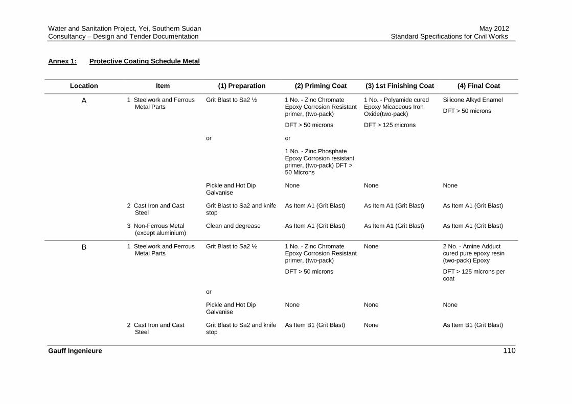
Water and Sanitation Project, Yei, Southern Sudan May 2012 Consultancy – Design and Tender Documentation Standard Specifications for Civil Works
Gauff Ingenieure 110
Annex 1: Protective Coating Schedule Metal
Location Item (1) Preparation (2) Priming Coat (3) 1st Finishing Coat (4) Final Coat
A 1 Steelwork and Ferrous Metal Parts
Grit Blast to Sa2 ½ 1 No. - Zinc Chromate Epoxy Corrosion Resistant primer, (two-pack)
DFT > 50 microns
1 No. - Polyamide cured Epoxy Micaceous Iron Oxide(two-pack)
DFT > 125 microns
Silicone Alkyd Enamel
DFT > 50 microns
or or
1 No. - Zinc Phosphate Epoxy Corrosion resistant primer, (two-pack) DFT > 50 Microns
Pickle and Hot Dip Galvanise
None None None
2 Cast Iron and Cast Steel
Grit Blast to Sa2 and knife stop
As Item A1 (Grit Blast) As Item A1 (Grit Blast) As Item A1 (Grit Blast)
3 Non-Ferrous Metal (except aluminium)
Clean and degrease As Item A1 (Grit Blast) As Item A1 (Grit Blast) As Item A1 (Grit Blast)
B 1 Steelwork and Ferrous Metal Parts
Grit Blast to Sa2 ½ 1 No. - Zinc Chromate Epoxy Corrosion Resistant primer, (two-pack)
DFT > 50 microns
None 2 No. - Amine Adduct cured pure epoxy resin (two-pack) Epoxy
DFT > 125 microns per coat
or
Pickle and Hot Dip Galvanise
None None None
2 Cast Iron and Cast Steel
Grit Blast to Sa2 and knife stop
As Item B1 (Grit Blast) None As Item B1 (Grit Blast)
Water and Sanitation Project, Yei, Southern Sudan May 2012 Consultancy – Design and Tender Documentation Standard Specifications for Civil Works
Gauff Ingenieure 111
3 Non-Ferrous Metal (except aluminium)
Clean and degrease As Item B1 (Grit Blast) None As Item B1 (Grit Blast)
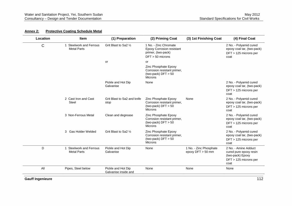
Water and Sanitation Project, Yei, Southern Sudan May 2012 Consultancy – Design and Tender Documentation Standard Specifications for Civil Works
Gauff Ingenieure 112
Annex 2: Protective Coating Schedule Metal
Location Item (1) Preparation (2) Priming Coat (3) 1st Finishing Coat (4) Final Coat
C 1 Steelwork and Ferrous Metal Parts
Grit Blast to Sa2 ½ 1 No. - Zinc Chromate Epoxy Corrosion resistant primer, (two-pack) DFT > 50 microns
2 No. - Polyamid cured epoxy coal tar, (two-pack) DFT > 125 microns per coat
or or
Zinc Phosphate Epoxy Corrosion resistant primer, (two-pack) DFT > 50 Microns
Pickle and Hot Dip Galvanise
None 2 No. - Polyamid cured epoxy coal tar, (two-pack) DFT > 125 microns per coat
2 Cast Iron and Cast Steel
Grit Blast to Sa2 and knife stop
Zinc Phosphate Epoxy Corrosion resistant primer, (two-pack) DFT > 50 Microns
None 2 No. - Polyamid cured epoxy coal tar, (two-pack) DFT > 125 microns per coat
3 Non-Ferrous Metal Clean and degrease Zinc Phosphate Epoxy Corrosion resistant primer, (two-pack) DFT > 50 Microns
2 No. - Polyamid cured epoxy coal tar, (two-pack) DFT > 125 microns per coat
3 Gas Holder Welded Grit Blast to Sa2 ½ Zinc Phosphate Epoxy Corrosion resistant primer, (two-pack) DFT > 50 Microns
2 No. - Polyamid cured epoxy coal tar, (two-pack) DFT > 125 microns per coat
D 1 Steelwork and Ferrous Metal Parts
Pickle and Hot Dip Galvanise
None 1 No. - Zinc Phosphate epoxy DFT > 50 mm
2 No. - Amine Adduct cured pure epoxy resin (two-pack) Epoxy DFT > 125 microns per coat
All Pipes, Steel below Pickle and Hot Dip Galvanise inside and
None None None
Water and Sanitation Project, Yei, Southern Sudan May 2012 Consultancy – Design and Tender Documentation Standard Specifications for Civil Works
Gauff Ingenieure 113
outside
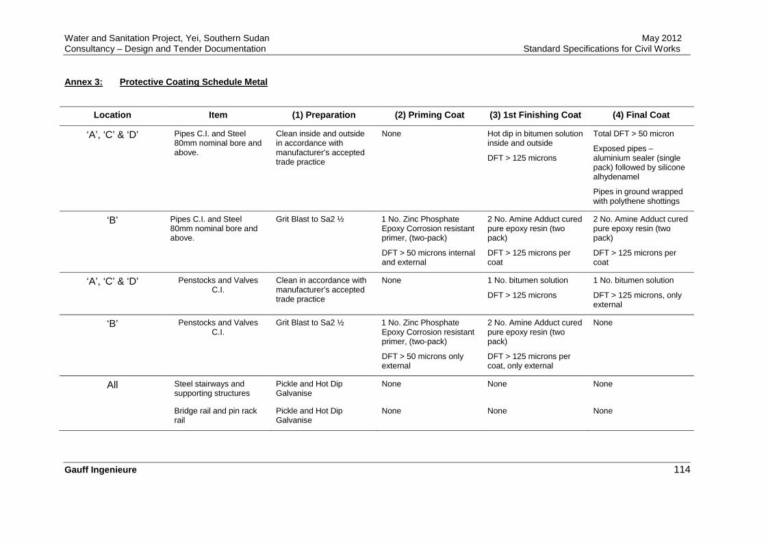
Water and Sanitation Project, Yei, Southern Sudan May 2012 Consultancy – Design and Tender Documentation Standard Specifications for Civil Works
Gauff Ingenieure 114
Annex 3: Protective Coating Schedule Metal
Location Item (1) Preparation (2) Priming Coat (3) 1st Finishing Coat (4) Final Coat
‘A’, ‘C’ & ‘D’ Pipes C.I. and Steel 80mm nominal bore and above.
Clean inside and outside in accordance with manufacturer’s accepted trade practice
None Hot dip in bitumen solution inside and outside
DFT > 125 microns
Total DFT > 50 micron
Exposed pipes – aluminium sealer (single pack) followed by silicone alhydenamel
Pipes in ground wrapped with polythene shottings
‘B’ Pipes C.I. and Steel 80mm nominal bore and above.
Grit Blast to Sa2 ½ 1 No. Zinc Phosphate Epoxy Corrosion resistant primer, (two-pack)
DFT > 50 microns internal and external
2 No. Amine Adduct cured pure epoxy resin (two pack)
DFT > 125 microns per coat
2 No. Amine Adduct cured pure epoxy resin (two pack)
DFT > 125 microns per coat
‘A’, ‘C’ & ‘D’ Penstocks and Valves C.I.
Clean in accordance with manufacturer’s accepted trade practice
None 1 No. bitumen solution
DFT > 125 microns
1 No. bitumen solution
DFT > 125 microns, only external
‘B’ Penstocks and Valves C.I.
Grit Blast to Sa2 ½ 1 No. Zinc Phosphate Epoxy Corrosion resistant primer, (two-pack)
DFT > 50 microns only external
2 No. Amine Adduct cured pure epoxy resin (two pack)
DFT > 125 microns per coat, only external
None
All Steel stairways and supporting structures
Pickle and Hot Dip Galvanise
None None None
Bridge rail and pin rack rail
Pickle and Hot Dip Galvanise
None None None

Water and Sanitation Project, Yei, Southern Sudan May 2012 Consultancy – Design and Tender Documentation Standard Specifications for Civil Works
Gauff Ingenieure 115
Annex 4: Protective Coating Schedule
Surface Environmental Conditions Primer Final Treat ment
Concrete and cement plaster High humidity 1 coat of a highly weather resistant synthetic resin thinned to manufacturer's instructions
2 coats of a highly weather- resistant synthetic resin based paint
Concrete Exposed to oil 1 coat with a plastic modified hydraulic mortar
3 coats of an oil resistant synthetic resin based paint
Concrete Exposed to chemical attack 8mm thick (minimum FRP lining -
Concrete Exposed to mechanical wear Covered with ironite flooring -
Concrete Exposed to oil 1 coat of chlorinated rubber-based paint, thinned to manufacturer’s instructions
2 coats of a 2-pack epoxy-based paint
Internal concrete and plastered walls
Exposed to minor abrasion - 3 coats of an oil-free synthetic resin-based dust-binding paint
Concrete flooring Exposed to minor mechanical wear
- 2 coats of an oil-free synthetic resin-based dust-binding paint
Internal plaster Exposed to normal conditions 1 coat of a polyvinyl-acetate dispersion type, non-chalking thinned to manufacturer’s instructions
2 coats of a polyvinyl-acetate type, non-chalking

Water and Sanitation Project, Yei, Southern Sudan May 2012 Consultancy – Design and Tender Documentation Standard Specifications for Civil Works
Gauff Ingenieure 116
Annex 5: Protective Coating Schedule
Kind of Wood Particular Preparation Primer Final Tr eatment
Softwood a) Sand down before primer
b) Treat knots
c) Sand down after primer
1 coat of fungicide and bactericide ingredients
2 coats of synthetic resin based lacquer with white active pigments
Plywood and Veneer a) Sand down before primer
b) Treat knots
c) Sand down after primer
1 coat of linseed oil 1 coat of oil paint and 1 coat of lustreless varnish
Hardwood a) Sand down before primer
b) Treat knots
c) Sand down after primer
1 coat of linseed oil 2 coats of colourless varnish