gaza power generation company 140 mw … sop-005- electrical.(r6...the gas turbine generators are...
TRANSCRIPT

GAZA POWER GENERATION COMPANY 140 MW CCGT POWER PLANT
GAZA ___________________________________________________________________________ SOP: 005(PART 1) REVISION 6 SECTION: 11KV ELECTRICAL DISTRIBUTION SYSTEM
GPGC SOP-005 Page 1 of 25 JAN,2012
Content CONTENT……………………………………………………………………………………. 1
1. SAFETY …………………………………………………………………………….………3
2. System Description …………………………………………………………………………5
2.1 The Electrical Distribution System ………………………………………………….5
2.2 11 KV SYSTEM …….............................................................................................6
3. BASE POSITION ...................................................................................................................7
3.1. BLOCK 1....................................................................................................................7
3.2. BLOCK 2 ..................................................................................................................7
4. OPERATION MODES……………………………………………………….......................8
4.1. DE-ENERGIZED 66 KV GRID…….......................................................................8 4.1.1. Operating Case............................................................................................................ 8
4.1.2. Start
Position…………………………………………………………………….…………….8
4.1.3. Sequence List.................................................................................................................8
4.2. ENERGIZED 66 KV GRID ……..............................................................................9 4.2.1. Operating Case............................................................................................................. 9
4.2.2. Start Position..................................................................................................................9
4.2.3. Sequence List.................................................................................................................9
4.3 ENERGIZED 11 KV SYSTEM ………………………………………...………....10
4.4. SYSTEM SHUT DOWN..........................................................................................11 4.4.1. Operating Case............................................................................................................11
4.4.2. Start Position............................................................................................................... 11
4.4.3. Sequence List............................................................................................................... 11

GAZA POWER GENERATION COMPANY 140 MW CCGT POWER PLANT
GAZA ___________________________________________________________________________ SOP: 005(PART 1) REVISION 6 SECTION: 11KV ELECTRICAL DISTRIBUTION SYSTEM
GPGC SOP-005 Page 2 of 25 JAN,2012
5. DISTURBANCE INSTRUCTION ……………...................................................................12
5.1 TRIPS ........................................................................................................................12 5.1.1 Block 11........................................................................................................................13
5.1.2 Block 13...................................................................................................................... .13
5.1.3 Block 22....................................................................................................................... 14
5.1.4 Block 24...................................................................................................................... 15
5.2 ALARMS.................................................................................................................. 16 5.2.1 Block 11....................................................................................................................... 16
5.2.2 Block 13....................................................................................................................... 17
5.2.3 Block 22....................................................................................................................... 19
5.2.4 Block 24........................................................................................................................20
6. System Modification…………………………………………………………………………22
7. System History……………………………………………………………………………….24
8. System PID …………….……………………………………………………………..……25

GAZA POWER GENERATION COMPANY 140 MW CCGT POWER PLANT
GAZA ___________________________________________________________________________ SOP: 005(PART 1) REVISION 6 SECTION: 11KV ELECTRICAL DISTRIBUTION SYSTEM
GPGC SOP-005 Page 3 of 25 JAN,2012
1. SAFETY
Before operating the Electrical Distribution System the owner, employers and staff should become familiar, and comply with, all applicable regulations and appropriate local codes, international standards and regulations relative to personal protective equipment. This includes eye and face protective equipment, respiratory protective equipment, equipment intended to protect the extremities, protective clothing, protective shields/barriers and electrical protective equipment as well as noise exposure administration and/or engineering controls and/or personal hearing protective equipment. NOTE: Nearly every plant function depends on the reliable operation of the electrical
distribution system. If you are unsure of the proper operation of a component, DO NOT operate it.
• When a circuit breaker has tripped due to a fault, never re-close that
breaker until the reason for the fault has been remedied and the relays reset. Always check for any actuated relays before resetting any electrical equipment.
• Before energizing any bus for the first time after maintenance, or
after a long shutdown, ensure that all the breakers on the bus are in the open position and all the relays are reset.
• Never start more than one high rated motor at a time which are
powered from the same bus. • Physically check the electrical equipment such as transformers,
breakers, and disconnectors before energizing them, especially after a long shutdown or maintenance.
• In general, energize electrical distribution systems starting from the
high voltage supply and working towards the low voltage components.
• Equipment interlocks should never be overridden. • When common trouble alarms are received at the DCS (Distributed
Control System), the problem should be investigated immediately to ensure the integrity of the electrical system.
• Do not attempt to operate equipment outside of its electrical limits.

GAZA POWER GENERATION COMPANY 140 MW CCGT POWER PLANT
GAZA ___________________________________________________________________________ SOP: 005(PART 1) REVISION 6 SECTION: 11KV ELECTRICAL DISTRIBUTION SYSTEM
GPGC SOP-005 Page 4 of 25 JAN,2012
• Always operate high voltage circuit breakers from their remote
control locations, unless emergency situations dictate local operation.
• Do not energize electrical equipment until all maintenance or repair
to the equipment has been completed and all tags are removed. • Become familiar with the specific precautions set forth in the vendor
instruction manuals for the equipment. These equipment specific precautions should be followed to avoid potential hazard or equipment damage.
• Always close and secure all switchgear and MCC panels and doors
before energizing a bus. • To minimize the hazard of electric shock or burn, approved
grounding practices must be strictly followed by wear personal protection equipment to be used during work

GAZA POWER GENERATION COMPANY 140 MW CCGT POWER PLANT
GAZA ___________________________________________________________________________ SOP: 005(PART 1) REVISION 6 SECTION: 11KV ELECTRICAL DISTRIBUTION SYSTEM
GPGC SOP-005 Page 5 of 25 JAN,2012
2.0 System Description 2.1 The Electrical Distribution System The Electrical Distribution System is one of the most critical systems in the plant. Nearly every system in the plant used to support the generation of power and steam depends on the electrical distribution system. This system serves many functions, including:
• Connecting the Electrical Generators to the Substation Transmission Lines • Supplying Electrical Power to Plant Auxiliary Loads (Motors, Heaters,
Lighting, etc.) • Providing Uninterruptible AC Power to Critical Plant Loads (DCS, etc.) • Providing Reliable DC Power (Control Power for Switchgear, etc.)
In order to safely provide all the functions listed above, the Electrical Distribution System contains many components and is necessarily a very complicated system. A detailed discussion of the technical design of the system is beyond the scope of this document; however, it is very important to understand the major components of the system and how it is operated safely. This manual will provide an understanding of the major components and will provide the information necessary to place the equipment in service and monitor its normal operation. Before beginning any discussion of the major components in the system, it is important to have an overall understanding of the entire system. Electrical single Line Drawing doucument No. 2414925 provides a greatly simplified picture of the major components and how they are connected in the system. Individual plant loads, such as pump motors, air compressors, etc., are not shown on this simplified drawing. In addition, protective relays and monitoring equipment are not shown. Once an overall view of the whole system is understood, it will be much easier to provide a detailed discussion of the individual subsystems and components including:
• Switchgear • Motor Control Centers • Disconnect Switches • Circuit Breakers • Motor Starters • Protective Relays • Power Transformers • Current and Potential Transformers

GAZA POWER GENERATION COMPANY 140 MW CCGT POWER PLANT
GAZA ___________________________________________________________________________ SOP: 005(PART 1) REVISION 6 SECTION: 11KV ELECTRICAL DISTRIBUTION SYSTEM
GPGC SOP-005 Page 6 of 25 JAN,2012
• Metering and Monitoring • Uninterruptible AC Power Supply and DC Power Supply • SFC
The Electrical Distribution System can be divided into five (5) subsystems as follows. Each is discussed briefly below.
1. 11KV System 2. 6 kV System 3. 400 V System and 220/110 V subsystems 4. UPS (Uninterruptible Power Supply) 5. 110 VDC Power System
2.2 11 KV SYSTEM
Each gas turbine generators supply 11 kV power to the 66 kV bus bar:
• GSU Transformer 1 – GT#11 • GSU Transformer 2 – GT#13+ST10 • GSU Transformer 3 – GT#22 • GSU Transformer 4 – GT#24+ST20
The Generator Step-Up Transformers change the voltage from 11kV on the low side, to 66 kV on the high side. The low side of each transformer is connected to a 11 kV bus that connects the associated Gas Turbine Generator, Station Auxiliary Transformer, and Station Services Transformers. The gas turbine generators are equipped with individual circuit breakers (11BAC01,13BAC01,22BAC01,24BAC01) located in MV switchgears block #1 & block #2. The circuit breakers are equipped with protective relays and include control and monitoring circuits. Each GTG is equipped with a motor operated disconnect switch. The motor operated disconnectors provide isolation from the 11 kV system for generator maintenance. The disconnectors are interlocked with the associated generator breaker, preventing breaker closure when the disconnector is open. *** Revio Hisory part.

GAZA POWER GENERATION COMPANY 140 MW CCGT POWER PLANT
GAZA ___________________________________________________________________________ SOP: 005(PART 1) REVISION 6 SECTION: 11KV ELECTRICAL DISTRIBUTION SYSTEM
GPGC SOP-005 Page 7 of 25 JAN,2012
3 Base Position 3.1 Block 1
Item Position DG1 OPEN Breaker to 66 kV switchyard 11BBA01 OPEN Disconnector to power transformer 11BBA02 OPEN Feeder to 6 kV system 11BAC01 OPEN Generator circuit breaker DG2 OPEN Breaker to 66 kV switchyard 13BBA01 OPEN Disconnector to power transformer 13BBA02 OPEN Feeder to 6 kV system 13BAC01 OPEN Generator circuit breaker
3.2 Block 2
Item Position DG4 OPEN Breaker to 66 kV switchyard 22BBA01 OPEN Disconnector to power transformer 22BBA02 OPEN Feeder to 6 kV system 22BAC01 OPEN Generator circuit breaker DG3 OPEN Breaker to 66 kV switchyard 24BBA01 OPEN Disconnector to power transformer 24BBA02 OPEN Feeder to 6 kV system 24BAC01 OPEN Generator circuit breaker
GAZA POWER GENERATION COMPANY 140 MW CCGT POWER PLANT
GAZA ___________________________________________________________________________ SOP: 005(PART 1) REVISION 6 SECTION: 11KV ELECTRICAL DISTRIBUTION SYSTEM
GPGC SOP-005 Page 8 of 25 JAN,2012
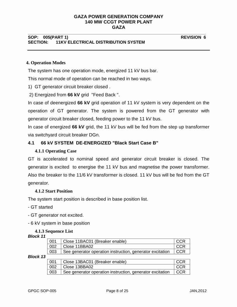
4. Operation Modes
The system has one operation mode, energized 11 kV bus bar.
This normal mode of operation can be reached in two ways.
1) GT generator circuit breaker closed .
2) Energized from 66 kV grid "Feed Back ".
In case of deenergized 66 kV grid operation of 11 kV system is very dependent on the
operation of GT generator. The system is powered from the GT generator with
generator circuit breaker closed, feeding power to the 11 kV bus.
In case of energized 66 kV grid, the 11 kV bus will be fed from the step up transformer
via switchyard circuit breaker DGn.
4.1 66 kV SYSTEM DE-ENERGIZED "Black Start Case B" 4.1.1 Operating Case
GT is accelerated to nominal speed and generator circuit breaker is closed. The
generator is excited to energise the 11 kV bus and magnetise the power transformer.
Also the breaker to the 11/6 kV transformer is closed. 11 kV bus will be fed from the GT
generator.
4.1.2 Start Position
The system start position is described in base position list.
- GT started
- GT generator not excited.
- 6 kV system in base position
4.1.3 Sequence List Block 11
001 Close 11BAC01 (Breaker enable) CCR 002 Close 11BBA02 CCR 003 See generator operation instruction, generator excitation CCR
Block 13 001 Close 13BAC01 (Breaker enable) CCR 002 Close 13BBA02 CCR 003 See generator operation instruction, generator excitation CCR
GAZA POWER GENERATION COMPANY 140 MW CCGT POWER PLANT
GAZA ___________________________________________________________________________ SOP: 005(PART 1) REVISION 6 SECTION: 11KV ELECTRICAL DISTRIBUTION SYSTEM
GPGC SOP-005 Page 9 of 25 JAN,2012
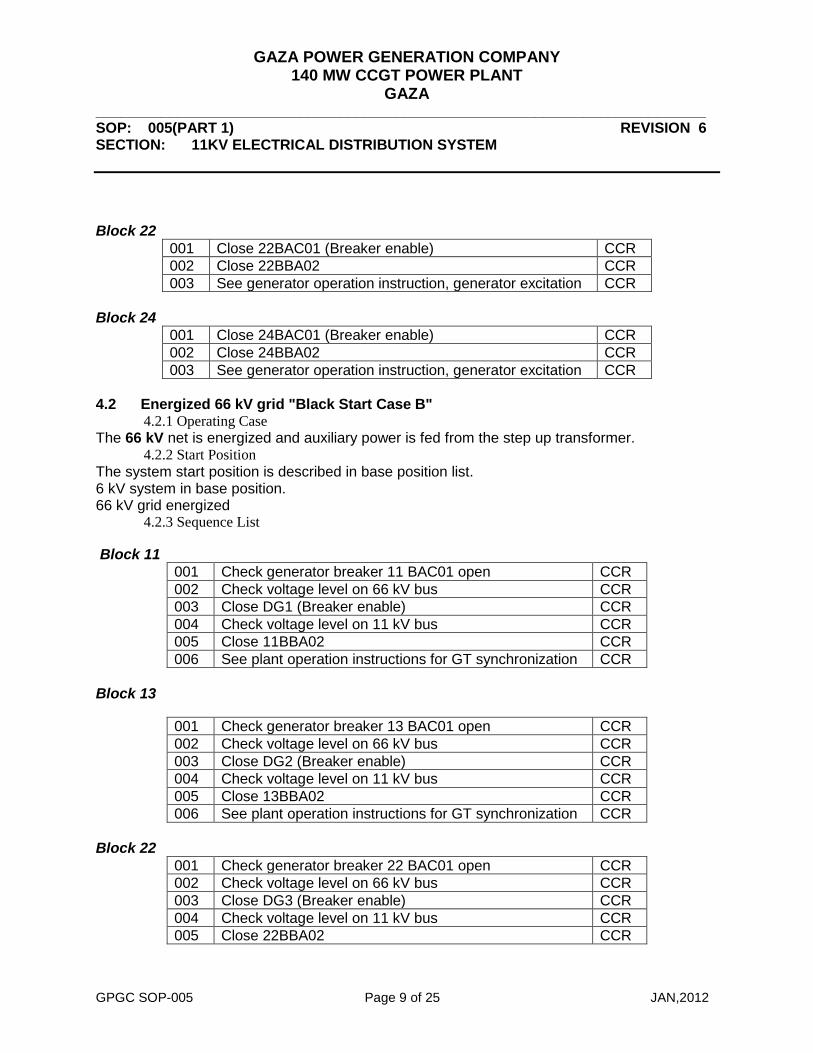
Block 22
001 Close 22BAC01 (Breaker enable) CCR 002 Close 22BBA02 CCR 003 See generator operation instruction, generator excitation CCR
Block 24
001 Close 24BAC01 (Breaker enable) CCR 002 Close 24BBA02 CCR 003 See generator operation instruction, generator excitation CCR
4.2 Energized 66 kV grid "Black Start Case B"
4.2.1 Operating Case The 66 kV net is energized and auxiliary power is fed from the step up transformer.
4.2.2 Start Position The system start position is described in base position list. 6 kV system in base position. 66 kV grid energized
4.2.3 Sequence List Block 11
001 Check generator breaker 11 BAC01 open CCR 002 Check voltage level on 66 kV bus CCR 003 Close DG1 (Breaker enable) CCR 004 Check voltage level on 11 kV bus CCR 005 Close 11BBA02 CCR 006 See plant operation instructions for GT synchronization CCR
Block 13
001 Check generator breaker 13 BAC01 open CCR 002 Check voltage level on 66 kV bus CCR 003 Close DG2 (Breaker enable) CCR 004 Check voltage level on 11 kV bus CCR 005 Close 13BBA02 CCR 006 See plant operation instructions for GT synchronization CCR
Block 22
001 Check generator breaker 22 BAC01 open CCR 002 Check voltage level on 66 kV bus CCR 003 Close DG3 (Breaker enable) CCR 004 Check voltage level on 11 kV bus CCR 005 Close 22BBA02 CCR
GAZA POWER GENERATION COMPANY 140 MW CCGT POWER PLANT
GAZA ___________________________________________________________________________ SOP: 005(PART 1) REVISION 6 SECTION: 11KV ELECTRICAL DISTRIBUTION SYSTEM
GPGC SOP-005 Page 10 of 25 JAN,2012
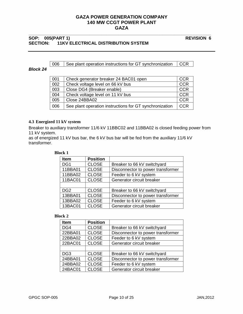
006 See plant operation instructions for GT synchronization CCR Block 24
001 Check generator breaker 24 BAC01 open CCR 002 Check voltage level on 66 kV bus CCR 003 Close DG4 (Breaker enable) CCR 004 Check voltage level on 11 kV bus CCR 005 Close 24BBA02 CCR 006 See plant operation instructions for GT synchronization CCR
4.3 Energized 11 kV system Breaker to auxiliary transformer 11/6 kV 11BBC02 and 11BBA02 is closed feeding power from 11 kV system. as of energized 11 kV bus bar, the 6 kV bus bar will be fed from the auxiliary 11/6 kV transformer.
Block 1 Item Position DG1 CLOSE Breaker to 66 kV switchyard 11BBA01 CLOSE Disconnector to power transformer 11BBA02 CLOSE Feeder to 6 kV system 11BAC01 CLOSE Generator circuit breaker DG2 CLOSE Breaker to 66 kV switchyard 13BBA01 CLOSE Disconnector to power transformer 13BBA02 CLOSE Feeder to 6 kV system 13BAC01 CLOSE Generator circuit breaker
Block 2 Item Position DG4 CLOSE Breaker to 66 kV switchyard 22BBA01 CLOSE Disconnector to power transformer 22BBA02 CLOSE Feeder to 6 kV system 22BAC01 CLOSE Generator circuit breaker DG3 CLOSE Breaker to 66 kV switchyard 24BBA01 CLOSE Disconnector to power transformer 24BBA02 CLOSE Feeder to 6 kV system 24BAC01 CLOSE Generator circuit breaker

GAZA POWER GENERATION COMPANY 140 MW CCGT POWER PLANT
GAZA ___________________________________________________________________________ SOP: 005(PART 1) REVISION 6 SECTION: 11KV ELECTRICAL DISTRIBUTION SYSTEM
GPGC SOP-005 Page 11 of 25 JAN,2012
4.4 System Shut down
4.4.1 Operating Case
The system returns to base position.
4.4.2 Start Position
The system is running.
GT is stopped
4.4.3 Sequence List Block 11
001 Check generator breaker 11 BAC01 open CCR 002 Open DG1 CCR 003 Open BBA02 CCR
Block 13
001 Check generator breaker 13 BAC01 open CCR 003 Open DG2 CCR 003 Open 13BBA02 CCR
Block 22
001 Check generator breaker 22 BAC01 open CCR 002 Open DG4 (Breaker enable) CCR 003 Open 22BBA02 CCR
Block 24
001 Check generator breaker 24 BAC01 open CCR 002 Open DG3 CCR 003 Open 24BBA02 CCR

GAZA POWER GENERATION COMPANY 140 MW CCGT POWER PLANT
GAZA ___________________________________________________________________________ SOP: 005(PART 1) REVISION 6 SECTION: 11KV ELECTRICAL DISTRIBUTION SYSTEM
GPGC SOP-005 Page 12 of 25 JAN,2012
5 Disturbance Instruction Disturbance generator breaker BAC, see GT documentation.
5.1 Trips 5.1.1 Block 11
Trip Cause Action Earth fault 11 kV bus 11BAC01GS001XN12 Earth fault in 11 kV system Trip DG1, 11BBA02.
Locate fault and repair. 11 kV arc detector 11BAC01GS001XN15 Serious fault in switchgear. Trip DG1, 11BAC01, 11BBA02.
Locate fault and repair. Sudden pressure relay 11BAT10CF005XH01N Buchholtz relay
High gas pressure in transformer, Transformer overload, short circuit
Trip DG1, 11BAC01, 11BBA02. Serious fault, See manufacturers instruction
Oil pressure OLTC 11BAT01CP010XH01
High load on OLTC Trip DG1, 11BAC01, 11BBA02. Locate fault and repair. See manufacturers instructions.
Transformer Oil temperature 11BAT10CT010XH01
Bad cooling, High load Trip DG1, 11BAC02, 11BBA02. Locate fault and repair. See manufacturers instructions.
High winding temp 11BAT10CT015XH01
Bad cooling of transformer, Transformer overload or short circuit
Trip DG1, 11BAC02, 11BBA02. Serious fault. See manufacturers instruction
differential trip relay 11BBA01GS001XN13 Short circuit or earth fault.
Trip DG1, 11BAC01, 11BBA02.11BBA01 Serious fault. Check location of fault and disconnect fault. See manufacturer instruction.
Breaker failure DG1 11BAY01EG007XE01 Breaker malfunction
Trip 11BAC01, 11BBA02. Check high voltage switchgear procedures.
Under voltage on 11 kV bus 11BBA01GS001XN12
Tap Changer position fault, voltage governor fault or tripped circuit breaker
Trip DG1, 11BAC01. Locate fault and repair.
Sudden pressure relay 11BBT10CF005XH01 Buchholtz relay
High gas pressure in transformer, Transformer overload, short circuit
Trip 11BBA02, 11BBC02 Serious fault, See manufacturers instruction .
Transformer Oil temperature 11BBT10CT005XH01
Bad cooling, High load Trip 11BBC02. Locate fault and repair. See manufacturers instructions.

GAZA POWER GENERATION COMPANY 140 MW CCGT POWER PLANT
GAZA ___________________________________________________________________________ SOP: 005(PART 1) REVISION 6 SECTION: 11KV ELECTRICAL DISTRIBUTION SYSTEM
GPGC SOP-005 Page 13 of 25 JAN,2012
5.1.2 Block 13 Trip Cause Action Earth fault 11 kV bus 13BAC01GS001XN12 Earth fault in 11 kV system Trip DG2, 13BBA01.
Locate fault and repair.13BBA03
11 kV arc detector 13BAC01GS001XN15 Serious fault in switchgear.
Trip DG2, 13BAC01, 13BBA01.13BBA03 Locate fault and repair.
Sudden pressure relay 13BAT10CF005XH01N Buchholtz relay
High gas pressure in transformer, Transformer overload, short circuit
Trip DG2, 13BBC02, 13BBA02. Serious fault, See manufacturers instruction
Oil pressure OLTC 13BAT01CP010XH01
High load on OLTC Trip DG2, 13BBC02, 13BBA03. Locate fault and repair. See manufacturers instructions.
Transformer Oil temperature 13BAT10CT010XH01
Bad cooling, High load Trip DG2, 13BBA03,13BBC02. Locate fault and repair. See manufacturers instructions.
High winding temp 13BAT10CT015XH01
Bad cooling of transformer, Transformer overload or short circuit
Trip DG2, 13BBC02, 13BBA03. Serious fault. See manufacturers instruction
Block differential trip 13BBA01GS001XN13 Short circuit or earth fault.
Trip DG2, 13BAC01, 13BBA03,13BBA01. Serious fault. Check location of fault and disconnect fault. See manufacturer instruction.
Breaker failure DG1 13BAY01EG007XE01 Breaker malfunction
Trip 13BAC01, 13BBA03. Check high voltage switchgear procedures.
Under voltage on 11 kV bus 13BBA01GS001XN12
Tap changer position fault, Voltage governor fault, tripped circuit breaker
Trip DG2, 13BAC01. Locate fault and repair.
Sudden pressure relay 13BBT10CF005XH01 Buchholtz relay
High gas pressure in transformer, Transformer overload, short circuit
Trip 13BBA02, 13BBC02 Serious fault, See manufacturers instruction .
Transformer Oil temperature 13BBT10CT005XH01
Bad cooling, High load Trip 13BBC02. Locate fault and repair. See manufacturers instructions.

GAZA POWER GENERATION COMPANY 140 MW CCGT POWER PLANT
GAZA ___________________________________________________________________________ SOP: 005(PART 1) REVISION 6 SECTION: 11KV ELECTRICAL DISTRIBUTION SYSTEM
GPGC SOP-005 Page 14 of 25 JAN,2012
5.1.3 Block 22 Trip Cause Action
Earth fault 11 kV bus 22BAC01GS001XN12 Earth fault in 11 kV system
Trip DG4, 22BBA02,22BAC01,22BBA01. Locate fault and repair.
11 kV arc detector 22BAC01GS001XN15 Serious fault in switchgear. Trip DG4, 22BBA01, 22BBA02.
Locate fault and repair.
Sudden pressure relay 22BAT10CF005XH01N Buchholtz relay
High gas pressure in transformer, Transformer overload, short circuit
Trip DG4, 22BBC02, 22BBA02. Serious fault, See manufacturers instruction
Oil pressure OLTC 22BAT01CP010XH01
High load on OLTC Trip DG4, 22BBC02, 22BBA02. Locate fault and repair. See manufacturers instructions.
Transformer Oil temperature 22BAT10CT010XH01
Bad cooling, High load Trip DG4, 22BBC02, 22BBA02. Locate fault and repair. See manufacturers instructions.
High winding temp 22BAT10CT015XH01
Bad cooling of transformer, Transformer overload or short circuit
Trip DG4, 22BBC02, 22BBA02. Serious fault. See manufacturers instruction
Differential trip relay 22BBA01GS001XN13 Short circuit or earth fault
Trip DG4, 22BAC01, 22BBA02,22BBA01. Serious fault. Check location of fault and disconnect fault. See manufacturer instruction.
Breaker failure DG1 22BAY01EG007XE01 Breaker malfunction
Trip 22BAC01, 22BBA02. Check high voltage switchgear procedures.
Under voltage on 11 kV bus 22BBA01GS001XN12
Tap changer position fault, Voltage governor fault, Tripped circuit breaker
Trip DG4, 22BAC01. Locate fault and repair.
Sudden pressure relay 22BBT10CF005XH01 Buchholtz relay
High gas pressure in transformer, Transformer overload, short circuit
Trip 22BBA02, 22BBC02 Serious fault, See manufacturers instruction .
Transformer Oil temperature 22BBT10CT005XH01
Bad cooling, High load Trip 22BBC02. Locate fault and repair. See manufacturers instructions.

GAZA POWER GENERATION COMPANY 140 MW CCGT POWER PLANT
GAZA ___________________________________________________________________________ SOP: 005(PART 1) REVISION 6 SECTION: 11KV ELECTRICAL DISTRIBUTION SYSTEM
GPGC SOP-005 Page 15 of 25 JAN,2012
5.1.4 Block 24 Trip Cause Action
Earth fault 11 kV bus 24BAC01GS001XN12 Earth fault in 11 kV system
Trip DG3, 24BBA03,24AC01,24BBA01. Locate fault and repair.
11 kV arc detector 24BAC01GS001XN15 Serious fault in switchgear.
Trip DG3, 24BAC01, 24BBA03,24BBA01. Locate fault and repair.
Sudden pressure relay 24BAT10CF005XH01N Buchholtz relay
High gas pressure in transformer, Transformer overload, short circuit
Trip DG3, 24BBC02, 24BBA03. Serious fault, See manufacturers instruction
Oil pressure OLTC 24BAT01CP010XH01
High load on OLTC Trip DG3, 24BBC02, 24BBA03. Locate fault and repair. See manufacturers instructions.
Transformer Oil temperature 24BAT10CT010XH01
Bad cooling, High load Trip DG3, 24BBC02, 24BBA03. Locate fault and repair. See manufacturers instructions.
High winding temp 24BAT10CT015XH01
Bad cooling of transformer, Transformer overload or short circuit
Trip DG3, 24BAC02, 24BBA03. Serious fault. See manufacturers instruction
Differential trip relay 24BBA01GS001XN13 Short circuit or earth fault.
Trip DG3, 24BAC01, 24BBA03,24BBA01. Serious fault. Check location of fault and disconnect fault. See manufacturer instruction.
Breaker failure DG1 24BAY01EG007XE01 Breaker malfunction
Trip 24BAC01, 24BBA02. Check high voltage switchgear procedures.
Under voltage on 11 kV bus 24BBA01GS001XN12
Tap changer fault, Voltage governor fault, Tripped circuit breaker
Trip DG3, 24BAC01. Locate fault and repair.
Sudden pressure relay 24BBT10CF005XH01 Buchholtz relay
High gas pressure in transformer, Transformer overload, short circuit
Trip 24BBA02, 24BBC02 Serious fault, See manufacturers instruction .
Transformer Oil temperature 24BBT10CT005XH01
Bad cooling, High load Trip 24BBC02. Locate fault and repair. See manufacturers instructions.

GAZA POWER GENERATION COMPANY 140 MW CCGT POWER PLANT
GAZA ___________________________________________________________________________ SOP: 005(PART 1) REVISION 6 SECTION: 11KV ELECTRICAL DISTRIBUTION SYSTEM
GPGC SOP-005 Page 16 of 25 JAN,2012
5.2 Alarms 5.2.1 Block 11
Alarm Cause Action
11BATCL001 < L1 Transformer Oil Level Low Oil leakage
Check transformer 11BAT10 for leakage see manufacturers instruction
11BAT10CL001 > H1 Transformer Oil Level High
Over filled transformer, temperature rise in transformer
Check transformer 11BAT10 status, see manufacturers instruction,check cooling system.
11 BAT10 CP001 > H1 Transformer pressure high
High gas pressure in transformer
Check transformer 11BAT10 cooling, decrease power to transformer, see manufacturers instruction,check cooling system.
11BAT10CT015 > H1 Winding temp alarm
Bad cooling of transformer, start of transformer overload
Check transformer 11BAT10 cooling, decrease power in transformer, see manufacturers instruction
11BAT10CT010 > H1 Oil temp alarm
Bad cooling of transformer, Transformer overload
Check transformer 11BAT10 cooling, decrease power in transformer, see manufacturers instruction
11BAT10CL010 > H1 OLTC high oil level
Over filled transformer, temperature rise in transformer
Check transformer 11BAT10 OLTC status, see manufacturers instruction
11BAT10CL010 < L1 OLTC low oil level Oil leakage
Check transformer 11BAT10 OLTC for leakage see manufacturers instruction
11BBA01GS001XN14 DC voltage in cubicle
Loss of power feeding to cubicle
Check battery power, check DC wiring in cubicle
11BAC01GS001XN13 DC voltage in cubicle
Loss of Power feeding to cubicle
Check battery power, check DC wiring in cubicle
11BAC01GS001XN11 Breaker alarm Breaker fault Check breaker according to
manufacturers instructions 11BBA02GS001XN13 DC voltage in cubicle
Loss of Power feeding to cubicle
Check battery power, check DC wiring in cubicle
11BBA02GS001XN11 Breaker alarm Fault inside breaker Check breaker according to
manufacturers instructions
GAZA POWER GENERATION COMPANY 140 MW CCGT POWER PLANT
GAZA ___________________________________________________________________________ SOP: 005(PART 1) REVISION 6 SECTION: 11KV ELECTRICAL DISTRIBUTION SYSTEM
GPGC SOP-005 Page 17 of 25 JAN,2012
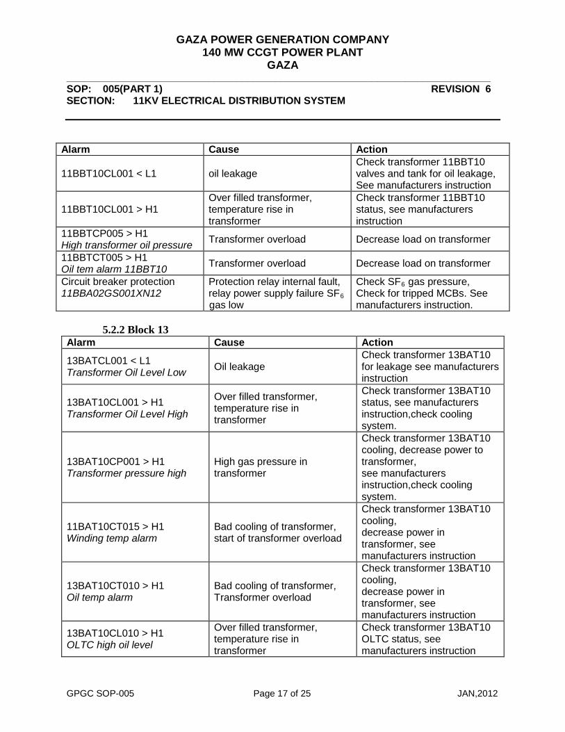
Alarm Cause Action
11BBT10CL001 < L1 oil leakage Check transformer 11BBT10 valves and tank for oil leakage, See manufacturers instruction
11BBT10CL001 > H1 Over filled transformer, temperature rise in transformer
Check transformer 11BBT10 status, see manufacturers instruction
11BBTCP005 > H1 High transformer oil pressure Transformer overload Decrease load on transformer
11BBTCT005 > H1 Oil tem alarm 11BBT10 Transformer overload Decrease load on transformer
Circuit breaker protection 11BBA02GS001XN12
Protection relay internal fault, relay power supply failure SF6 gas low
Check SF6 gas pressure, Check for tripped MCBs. See manufacturers instruction.
5.2.2 Block 13
Alarm Cause Action
13BATCL001 < L1 Transformer Oil Level Low Oil leakage
Check transformer 13BAT10 for leakage see manufacturers instruction
13BAT10CL001 > H1 Transformer Oil Level High
Over filled transformer, temperature rise in transformer
Check transformer 13BAT10 status, see manufacturers instruction,check cooling system.
13BAT10CP001 > H1 Transformer pressure high
High gas pressure in transformer
Check transformer 13BAT10 cooling, decrease power to transformer, see manufacturers instruction,check cooling system.
11BAT10CT015 > H1 Winding temp alarm
Bad cooling of transformer, start of transformer overload
Check transformer 13BAT10 cooling, decrease power in transformer, see manufacturers instruction
13BAT10CT010 > H1 Oil temp alarm
Bad cooling of transformer, Transformer overload
Check transformer 13BAT10 cooling, decrease power in transformer, see manufacturers instruction
13BAT10CL010 > H1 OLTC high oil level
Over filled transformer, temperature rise in transformer
Check transformer 13BAT10 OLTC status, see manufacturers instruction

GAZA POWER GENERATION COMPANY 140 MW CCGT POWER PLANT
GAZA ___________________________________________________________________________ SOP: 005(PART 1) REVISION 6 SECTION: 11KV ELECTRICAL DISTRIBUTION SYSTEM
GPGC SOP-005 Page 18 of 25 JAN,2012
Alarm Cause Action
13BAT10CL010 < L1 OLTC low oil level Oil leakage
Check transformer 13BAT10 OLTC for leakage see manufacturers instruction
13BBA01GS001XN14 DC voltage in cubicle
Loss of power feeding to cubicle
Check battery power, check DC wiring in cubicle
13BAC01GS001XN13 DC voltage in cubicle
Loss of Power feeding to cubicle
Check battery power, check DC wiring in cubicle
13BAC01GS001XN11 Breaker alarm Breaker fault Check breaker according to
manufacturers instructions 13BBA02GS001XN13 DC voltage in cubicle
Loss of Power feeding to cubicle
Check battery power, check DC wiring in cubicle
13BBA02GS001XN11 Breaker alarm Fault inside breaker Check breaker according to
manufacturers instructions
13BBT10CL001 < L1 Low transformer oil level oil leakage
Check transformer 13BBT10 valves and tank for oil leakage, See manufacturers instruction
13BBT10CL001 > H1 High transformer oil level
Over filled transformer, temperature rise in transformer
Check transformer 13BBT10 status, see manufacturers instruction
13BBT10CP005 > H1 High transformer oil pressure Transformer overload Decrease load on transformer
13BBTCT005 > H1 Oil tem alarm 11BBT10 Transformer overload Decrease load on transformer
Circuit breaker protection 13BBA02GS001XN12
Protection relay internal fault, relay power supplyfailure SF6 gas low
Check SF6 gas pressure, Check for tripped MCBs. See manufacturers instruction.

GAZA POWER GENERATION COMPANY 140 MW CCGT POWER PLANT
GAZA ___________________________________________________________________________ SOP: 005(PART 1) REVISION 6 SECTION: 11KV ELECTRICAL DISTRIBUTION SYSTEM
GPGC SOP-005 Page 19 of 25 JAN,2012
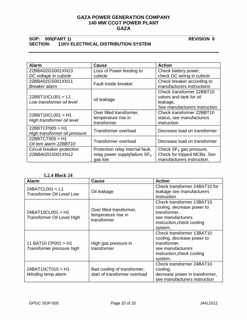
5.2.3 Block 22
Alarm Cause Action
22BATCL001 < L1 Transformer Oil Level Low Oil leakage
Check transformer 22BAT10 for leakage see manufacturers instruction
22BAT10CL001 > H1 Transformer Oil Level High
Over filled transformer, temperature rise in transformer
Check transformer 13BAT10 cooling, decrease power to transformer, see manufacturers instruction,check cooling system.
22BAT10CP001 > H1 Transformer pressure high
High gas pressure in transformer
Check transformer 13BAT10 cooling, decrease power to transformer, see manufacturers instruction,check cooling system.
22BAT10CT015 > H1 Winding temp alarm
Bad cooling of transformer, start of transformer overload
Check transformer 22BAT10 cooling, decrease power in transformer, see manufacturers instruction
22BAT10CT010 > H1 Oil temp alarm
Bad cooling of transformer, Transformer overload
Check transformer 22BAT10 cooling, decrease power in transformer, see manufacturers instruction
22BAT10CL010 > H1 OLTC high oil level
Over filled transformer, temperature rise in transformer
Check transformer 22BAT10 OLTC status, see manufacturers instruction
11BAT10CL010 < L1 OLTC low oil level Oil leakage
Check transformer 22BAT10 OLTC for leakage see manufacturers instruction
22BBA01GS001XN14 DC voltage in cubicle
Loss of power feeding to cubicle
Check battery power, check DC wiring in cubicle
22BAC01GS001XN13 DC voltage in cubicle
Loss of Power feeding to cubicle
Check battery power, check DC wiring in cubicle
22BAC01GS001XN11 Breaker alarm Breaker fault Check breaker according to
manufacturers instructions
GAZA POWER GENERATION COMPANY 140 MW CCGT POWER PLANT
GAZA ___________________________________________________________________________ SOP: 005(PART 1) REVISION 6 SECTION: 11KV ELECTRICAL DISTRIBUTION SYSTEM
GPGC SOP-005 Page 20 of 25 JAN,2012
Alarm Cause Action 22BBA02GS001XN13 DC voltage in cubicle
Loss of Power feeding to cubicle
Check battery power, check DC wiring in cubicle
22BBA02GS001XN11 Breaker alarm Fault inside breaker Check breaker according to
manufacturers instructions
22BBT10CL001 < L1 Low transformer oil level oil leakage
Check transformer 22BBT10 valves and tank for oil leakage, See manufacturers instruction
22BBT10CL001 > H1 High transformer oil level
Over filled transformer, temperature rise in transformer
Check transformer 22BBT10 status, see manufacturers instruction
22BBTCP005 > H1 High transformer oil pressure Transformer overload Decrease load on transformer
22BBTCT005 > H1 Oil tem alarm 22BBT10 Transformer overload Decrease load on transformer
Circuit breaker protection 22BBA02GS001XN12
Protection relay internal fault, relay power supplyfailure SF6 gas low
Check SF6 gas pressure, Check for tripped MCBs. See manufacturers instruction.
5.2.4 Block 24
Alarm Cause Action
24BATCL001 < L1 Transformer Oil Level Low Oil leakage
Check transformer 24BAT10 for leakage see manufacturers instruction
24BAT10CL001 > H1 Transformer Oil Level High
Over filled transformer, temperature rise in transformer
Check transformer 13BAT10 cooling, decrease power to transformer, see manufacturers instruction,check cooling system.
11 BAT10 CP001 > H1 Transformer pressure high
High gas pressure in transformer
Check transformer 13BAT10 cooling, decrease power to transformer, see manufacturers instruction,check cooling system.
24BAT10CT015 > H1 Winding temp alarm
Bad cooling of transformer, start of transformer overload
Check transformer 24BAT10 cooling, decrease power in transformer, see manufacturers instruction

GAZA POWER GENERATION COMPANY 140 MW CCGT POWER PLANT
GAZA ___________________________________________________________________________ SOP: 005(PART 1) REVISION 6 SECTION: 11KV ELECTRICAL DISTRIBUTION SYSTEM
GPGC SOP-005 Page 21 of 25 JAN,2012
Alarm Cause Action
24BAT10CT010 > H1 Oil temp alarm
Bad cooling of transformer, Transformer overload
Check transformer 24BAT10 cooling, decrease power in transformer, see manufacturers instruction
24BAT10CL010 > H1 OLTC high oil level
Over filled transformer, temperature rise in transformer
Check transformer 24BAT10 OLTC status, see manufacturers instruction
24BAT10CL010 < L1 OLTC low oil level Oil leakage
Check transformer 24BAT10 OLTC for leakage see manufacturers instruction
24BBA01GS001XN14 DC voltage in cubicle
Loss of power feeding to cubicle
Check battery power, check DC wiring in cubicle
24BAC01GS001XN13 DC voltage in cubicle
Loss of Power feeding to cubicle
Check battery power, check DC wiring in cubicle
24BAC01GS001XN11 Breaker alarm Breaker fault Check breaker according to
manufacturers instructions 24BBA02GS001XN13 DC voltage in cubicle
Loss of Power feeding to cubicle
Check battery power, check DC wiring in cubicle
24BBA02GS001XN11 Breaker alarm Fault inside breaker Check breaker according to
manufacturers instructions
24BBT10CL001 < L1 oil leakage Check transformer 24BBT10 valves and tank for oil leakage, See manufacturers instruction
24BBT10CL001 > H1 Over filled transformer, temperature rise in transformer
Check transformer 24BBT10 status, see manufacturers instruction
24BBTCP005 > H1 High transformer oil pressure Transformer overload Decrease load on transformer
24BBTCT005 > H1 Oil tem alarm 11BBT10 Transformer overload Decrease load on transformer
Circuit breaker protection 24BBA02GS001XN12
Protection relay internal fault, relay power supplyfailure SF6 gas low
Check SF6 gas pressure, Check for tripped MCBs. See manufacturers instruction.

GAZA POWER GENERATION COMPANY 140 MW CCGT POWER PLANT
GAZA ___________________________________________________________________________ SOP: 005(PART 1) REVISION 6 SECTION: 11KV ELECTRICAL DISTRIBUTION SYSTEM
GPGC SOP-005 Page 22 of 25 JAN,2012
6. System Modification
1- ELMACO STEP UP TRANSFORMERS 11/66KV 25MVA EL-NASR TRANSFORMERS & ELECRICAL PRODUCT CO.
After Bombing of the step-up transformer 11/220KV by Israel army the 220KV network replaced
by 66KV network .
the burned transformers removed and install new transformers work on 66KV network by
Egyptian transformers "ELMACO Company".
From GAZA Power Plant side:
- Unit 13: Remove the burned step up transformer and install new two step up
transformers connected on parallel 11/66KV 25MVA.
- Unit 11 : Remove the burned step up transformer and install new one step up
transformers 11/66KV 25MVA
- Unit 22 : Remove the burned step up transformer and install new one step up
transformers 11/66KV 25MVA
- Unit 24: Remove the burned step up transformer and not install other transformers yet.
But made connection by cables on switchyard from out 11KV Bus Bar of unit24 with
unit 13 to use the step up transformers in case of GT13 and ST10 shut down also by
connect data of transformer terminal protection "ret" of 24 instead of 13.
2- 11KV Grounding transformer / Earthling Resistor Siemens industrial turbo machinery AB Gaza`
There are four 11KV switchgears on Gaza Power Plant (GPP), and each switchgear
shall have an 11KV Grounding Transformer with earthling resistor.
This 11KV grounding transformer shall stabilized the neutral point on the 11KV
system during the time the generator connected to 11KV switchgear is not running
and energized.

GAZA POWER GENERATION COMPANY 140 MW CCGT POWER PLANT
GAZA ___________________________________________________________________________ SOP: 005(PART 1) REVISION 6 SECTION: 11KV ELECTRICAL DISTRIBUTION SYSTEM
GPGC SOP-005 Page 23 of 25 JAN,2012
The 11KV grounding transformers with ear thing resistor consist of one
transformer 11/0.69KV.one resistor connected to earth .automatic functions.
• Electrical installation - The four 11KV grounding transformers placed at the same place as
11,13,22,24BBT10 11/6KV transformers.
- The electrical installations were in three parts: LV, MV and programming of central
control system.
- LV Power each of 11KV Grounding Transformer needs LV power supply, 110VDC
to control equipment and 130VAC for cubical heater.
- The 11KV Grounding Transformer are connected to the existing grounding system.
- MV connecting point between 11KV Grounding Transformer and 11KV side of 11,
13, 22,24BBT10 transformers.
- The 11KV Grounding Transformer has an automatic function to stabilize the neutral
point.
This is to burn (heat) energy with a resistor connected to earth.
The function can only be in operation when the generator is not running and
energized.
- Operating of 11KV Grounding Transformer: the central control system will use the
signal of open and close indication of generator breaker to operate the 11KV
Grounding Transformer.
- Indication: the indication from the 11KV Grounding Transformer will be connected
to the central operation system. Alarms will appear on alarm list in central control.
7. System History

GAZA POWER GENERATION COMPANY 140 MW CCGT POWER PLANT
GAZA ___________________________________________________________________________ SOP: 005(PART 1) REVISION 6 SECTION: 11KV ELECTRICAL DISTRIBUTION SYSTEM
GPGC SOP-005 Page 24 of 25 JAN,2012

GAZA POWER GENERATION COMPANY 140 MW CCGT POWER PLANT
GAZA ___________________________________________________________________________ SOP: 005(PART 1) REVISION 6 SECTION: 11KV ELECTRICAL DISTRIBUTION SYSTEM
GPGC SOP-005 Page 25 of 25 JAN,2012
8. System PID