gb operating instructions - ewm ag · originaldokument liegt jedem gerät bei! hine! original...
TRANSCRIPT
EWM HIGHTEC WELDING GmbH
Dr. Günter - Henle - Straße 8 • D-56271 Mündersbach Phone: +49 (0)2680.181-0 • Fax: +49 (0)2680.181-244
www.ewm.de • [email protected]
GB Operating instructions
Plasma welding torch for plasma welding
• PWH 100 manual welding torch
• PWM 100 machine welding torch
• PWH 150 manual welding torch
• PWM 150 machine welding torch
• PWH 150 manual welding torch with cold wire feed
• PWM 150-ROB 20° robot welding torch with cold wire feed
N. B. These operating instructions must be read before commissioning. Failure to do so may be dangerous. Machines may only be operated by personnel who are familiar with the appropriate safety regulations.
© 2005 Subject to alteration. Item No.: 099-008231-EWM01 Date: 25.10.2005

Originaldokument
liegt jedem Gerät bei!
Original document
is enclosed with each machine!
Document original
est joint à toute machine!
EG - KonformitätserklärungEU - conformity declaration
Déclaration de Conformité de U.E.
Name des Herstellers:Name of manufacturer:Nom du fabricant:
EWM HIGHTEC WELDING GmbH(nachfolgend EWM genannt)(In the following called EWM)(nommé par la suite EWM)
Anschrift des Herstellers:Address of manufacturer:Adresse du fabricant:
Dr.- Günter - Henle - Straße 8D - 56271 Mündersbach – [email protected]
Hiermit erklären wir, daß dasnachstehend bezeichnete Gerät inseiner Konzeption und Bauart sowie inder von uns in Verkehr gebrachtenAusführung den grundlegendenSicherheits-anforderungen der untengenannten EG- Richtlinien entspricht.Im Falle von unbefugtenVeränderungen, unsachgemäßenReparaturen und / oder unerlaubtenUmbauten, die nicht ausdrücklich vonEWM autorisiert sind, verliert dieseErklärung ihre Gültigkeit.
We herewith declare that the machinedescribed below meets the standard safetyregulations of the EU- guidelinesmentionned below in its conception andconstruction, as well as in the design putinto circulation by us. In case ofunauthorized changes, improper repairsand / or unauthorized modifications, whichhave not been expressly allowed by EWM,this declaration will lose its validity.
Par la présente, nous déclarons que laconception et la construction ainsi que lemodèle, mis sur le marché par nous, del´appareil décrit ci - dessouscorrespondent aux directivesfondamentales de sécurité de la U.E.mentionnées ci- dessous. En cas dechangements non autorisés, deréparations inadéquates et / ou demodifications prohibeés, qui n´ont pas étéautorisés expressément par EWM, cettedéclaration devient caduque.
Gerätebezeichnung:Description of the machine:Déscription de la machine:
Gerätetyp:Type of machine:Type de machine:
Artikelnummer EWM:Article number:Numéro d´article
Seriennummer:Serial number:Numéro de série:
Optionen:Options:Options:
keinenoneaucune
Zutreffende EG - Richtlinien:Applicable EU - guidelines:Directives de la U.E. applicables:
EG - Niederspannungsrichtlinie (73/23/EWG)EU - low voltage guidelineDirective de la U.E. pour basses tensionsEG- EMV- Richtlinie (89/336/EWG)EU- EMC guidelineU.E.- EMC directive
Angewandte harmonisierte Normen:Used co-ordinated norms:Normes harmonisées appliquées:
EN 60974 / IEC 60974 / VDE 0544EN 50199 / VDE 0544 Teil 206
Hersteller - Unterschrift:Signature of manufacturer:Signature du fabricant:
Michael Szczesny , Geschäftsführermanaging directorgérant
05.2000

Table of contents Seite
Safety instructions ............................................................................................................................. S/1 For your safety ........................................................................................................................... S/1 Ambient conditions..................................................................................................................... S/2 Notes on the use of these operating instructions....................................................................... S/3
1 Technical data ...........................................................................................................................1/1 1.1 PWH/PWM 100.................................................................................................................1/1 1.2 PWH/PWM 150.................................................................................................................1/1 1.3 Torch variants and main dimensions ................................................................................1/2
1.3.1 PWH/PWM 100.......................................................................................................1/2 1.3.2 PWH/PWM 150.......................................................................................................1/2
2 Torch description......................................................................................................................2/1 2.1 Torch connections.............................................................................................................2/1 2.2 Torch layout ......................................................................................................................2/2
2.2.1 PWH/PWM 100.......................................................................................................2/2 2.2.2 PWH/PWM 150.......................................................................................................2/3 2.2.3 PWH 150 HKD with cold wire feed.........................................................................2/4 2.2.4 PWM 150-ROB 20° with cold wire feed .................................................................2/5
2.3 Torch components ............................................................................................................2/6 2.3.1 Torch body..............................................................................................................2/6 2.3.2 Plasma nozzles ......................................................................................................2/6 2.3.3 Electrode seat in the PWH 100 ..............................................................................2/6 2.3.4 Electrode seat in the PWM 150..............................................................................2/6
2.4 Torch cooling ....................................................................................................................2/7 2.5 Disassembling and assembling the PWH/PWM 100........................................................2/8
2.5.1 Replacing the electrode..........................................................................................2/8 2.5.1.1 Removing the electrode .....................................................................2/8 2.5.1.2 Installing the new electrode ...............................................................2/9
2.5.2 Full disassembly ...................................................................................................2/10 2.5.3 Assembly ..............................................................................................................2/11 2.5.4 Setting the electrode position ...............................................................................2/12 2.5.5 Acoustic setting of the electrode position .............................................................2/12
2.6 Disassembling and assembling the PWH/PWM 150......................................................2/13 2.6.1 Replacing the electrode........................................................................................2/13
2.6.1.1 Removing the electrode ...................................................................2/13 2.6.1.2 Installing the new electrode .............................................................2/14
2.6.2 Full disassembly ...................................................................................................2/15 2.6.3 Assembly ..............................................................................................................2/16 2.6.4 Setting the electrode position ...............................................................................2/17
2.7 Setting values for the electrode position.........................................................................2/18 2.7.1 Setting values with the electrode on the minus pole ............................................2/18 2.7.2 Operation with plus pole of the electrode or alternating current...........................2/18
3 Commissioning .........................................................................................................................3/1 3.1 Proper usage ....................................................................................................................3/1 3.2 Connection to the power source .......................................................................................3/1 3.3 Welding mode ...................................................................................................................3/2
3.3.1 Preparations ...........................................................................................................3/2 3.3.2 Start of welding.......................................................................................................3/2 3.3.3 Setting the electrode...............................................................................................3/2 3.3.4 Nozzle selection .....................................................................................................3/2 3.3.5 Double arc ..............................................................................................................3/3 3.3.6 Grinding the electrode ............................................................................................3/3
Contents/1
Table of contents Seite 3.4 Welding parameters..........................................................................................................3/4
3.4.1 Main welding parameters .......................................................................................3/4 3.4.2 Plasma gas quantity ...............................................................................................3/4 3.4.3 Keyhole welding .....................................................................................................3/4 3.4.4 Plasma gas selection..............................................................................................3/4 3.4.5 Shielding gas quantity ............................................................................................3/4 3.4.6 Shielding gas selection...........................................................................................3/4
3.5 Load tables for plasma nozzles ........................................................................................3/5 3.5.1 Electrode on the minus pole ...................................................................................3/5 3.5.2 Electrode on the plus pole ......................................................................................3/5
4 Maintenance and repair ............................................................................................................4/1 4.1 Maintenance work.............................................................................................................4/1
4.1.1 Daily maintenance tasks.........................................................................................4/1 4.1.2 Monthly maintenance tasks ....................................................................................4/1
4.2 Repairs..............................................................................................................................4/1
5 List of spare parts and replacement parts .............................................................................5/1 PWH/PWM 100 ...........................................................................................................................5/1 PWH/PWM 150 ...........................................................................................................................5/3 PWH 150 HKD with cold wire feed .............................................................................................5/5 PWH 150-ROB 20° with cold wire feed ......................................................................................5/7
Contents/1

Safety instructions
S / 1
For your safety
Ignoring the following safety precautions can be fatal! Observe accident prevention regulations. These operating instructions are valid only in combination with the operating instructions for the relevant welding machine from our product range.
Proper usage
This torch has been manufactured according to the latest developments in technology and current regulations and standards. It should be operated only for the use for which it was designed (see chapter Commissioning).
Improper usage
This torch may be a hazard to persons, animals and property, however, if it is
• not used as designed
• operated by unskilled persons who have not been trained,
• modified or converted improperly
Our operating instructions introduce you to the safe use of the torch. Therefore please read them carefully and only start work when you are familiar with them.
Any person involved in operation, maintenance and repair of this torch must read and follow these operating instructions, especially the safety precautions. Where appropriate, this must be confirmed by signature.
Furthermore, the
• relevant accident prevention regulations,
• generally recognised safety regulations,
• local regulations, etc. must be observed.
Safety instructions specific to the torch
This torch is very different from other torches!
For this reason, ensure that these operating instructions are available to the operator and are also read before the torch is commissioned!
• When replacing replaceable parts such as plasma nozzles, electrodes, etc., and when attaching and detaching the torch on the power source, the power source must be switched off. During all other maintenance work on the welding torch, the torch must be unscrewed from the system.
The connection socket for the acoustic electrode adjustment unit on the tube package of the machine welding torch must be closed at all times!
High frequency!
Use the red plastic cap supplied for this purpose.
• Crown nuts on power/water lines, adapters etc. must be insulated or protected against being touched accidentally!
• Torches and tube packages must be handled with care and protected against damp and against mechanical, chemical and thermal damage, and should be checked at regular intervals.
• The values given in the operating instructions are maximum values, i.e. limit values. If these values are exceeded, the torch could be damaged or destroyed.
• The high process temperature of the plasma beam causes metal vapour to be formed. Appropriate measures should be used to ensure that the relevant regulations and the maximum permissible TRK and MAK values are observed.
• Please note that it is the responsibility of the company management and the welding supervisory staff to ensure that all safety regulations are strictly observed when carrying out welding work, in particular the legal and statutory accident prevention regulations of the relevant country.
Safety instructions
S / 2
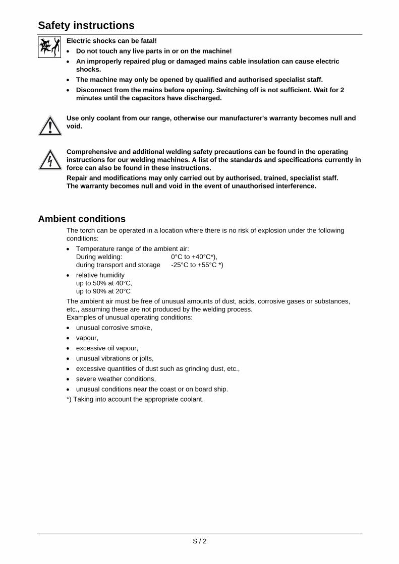
Electric shocks can be fatal!
• Do not touch any live parts in or on the machine!
• An improperly repaired plug or damaged mains cable insulation can cause electric shocks.
• The machine may only be opened by qualified and authorised specialist staff.
• Disconnect from the mains before opening. Switching off is not sufficient. Wait for 2 minutes until the capacitors have discharged.
Use only coolant from our range, otherwise our manufacturer's warranty becomes null and void.
Comprehensive and additional welding safety precautions can be found in the operating instructions for our welding machines. A list of the standards and specifications currently in force can also be found in these instructions.
Repair and modifications may only carried out by authorised, trained, specialist staff. The warranty becomes null and void in the event of unauthorised interference.
Ambient conditions The torch can be operated in a location where there is no risk of explosion under the following conditions:
• Temperature range of the ambient air: During welding: 0°C to +40°C*), during transport and storage -25°C to +55°C *)
• relative humidity up to 50% at 40°C, up to 90% at 20°C
The ambient air must be free of unusual amounts of dust, acids, corrosive gases or substances, etc., assuming these are not produced by the welding process. Examples of unusual operating conditions:
• unusual corrosive smoke,
• vapour,
• excessive oil vapour,
• unusual vibrations or jolts,
• excessive quantities of dust such as grinding dust, etc.,
• severe weather conditions,
• unusual conditions near the coast or on board ship.
*) Taking into account the appropriate coolant.
Safety instructions
S / 3
Notes on the use of these operating instructions
Our operating instructions introduce you to the safe use of the torch. Therefore please read them carefully and only start work when you are familiar with them.
These operating instructions are arranged into chapters.
To help you find your way around more quickly, in the margins you will occasionally see symbols along with the sub-headings. These symbols refer to particularly important passages of text which are graded as follows depending on their importance:
(Note): Applies to special technical features which must be observed by the user.
(Warning): Applies to working and operating procedures which must be carefully followed to avoid damaging or destroying the torch.
(Caution): Applies to working and operating procedures which must be carefully followed to avoid endangering people and includes the "Warning" symbol.

1 Technical data
1 / 1
1.1 PWH/PWM 100 Power range,
maximum value at 100% DC:
0.5 – 100 A with – pole on the electrode (1.5 and 2.4 mm Ø)
max. 80 A in alternating current mode (3.2 mm Ø)
max. 35 A with + pole on the electrode (3.2 mm Ø)
Pilot arc current: 2 – 10 A
Plasma gas: Argon
Shielding gases: Argon, argon/hydrogen (approx. 95/5%), argon/helium, helium
argon/active gas mixtures
Cooling system: Liquid cooling
Cooling medium: Deionised water (free of dissolved minerals)
Absolutely free of impurities, not electrically conductive
Coolant pressure: max. 4.5 bar
Minimum coolant flow rate: 1.2 litres per minute, measured at the tube package outlet
Coolant temperature on the torch inlet:
max. 35°C,
Recommended torch inlet temperature: 12° to 20°C
1.2 PWH/PWM 150 Power range,
maximum value at 100% DC:
0.5 – 150 A with - pole of the electrode (1.5 & 2.4 mm Ø) max. 120 A with AC operation (3.2 mm Ø) max. 50 A with + pole of the electrode (3.2 mm Ø)
Pilot arc current: 2 – 12 A PWH 150 KD; (2 – 30 A PWM 150 KD)
Plasma gas: Argon
Shielding gases: Argon, argon/hydrogen (approx. 95/5%), argon/helium, helium
argon/active gas mixtures
Cooling system: Liquid cooling
Cooling medium: Deionised water (free from dissolved minerals) absolutely free of impurities, not electrically conductive
Coolant pressure: max. 4.5 bar
Minimum coolant flow rate: 1.2 litres per minute, measured at the tube package outlet
Coolant temperature on the torch inlet:
Max. 35°C, recommended torch inlet temperature: 12° to 20°C

1 Technical data
1 / 2
1.3 Torch variants and main dimensions
1.3.1 PWH/PWM 100
ø22
58
ø18
Fig. 1: PWH 100 manual welding torch with torch trigger
Fig. 2: PWM 100 machine welding torch
1.3.2 PWH/PWM 150
Fig. 5: PWH 150 manual welding torch with torch trigger
Fig. 3: PWM 150 machine welding torch
Fig. 4: PWM 150 ROB 20° robot welding torch
Fig. 6: PWH 150 manual welding torch with cold wire feed
2 Torch description
2.1 Torch connections
A1B1
C1
D1
E1
F1
G1
H1
I1
A1B1
C1
D1
E1
F1
G1
H1
I1
Fig. 1: Torch connection PWH/PWM 100 Fig. 2: Torch connection PWH/PWM 150
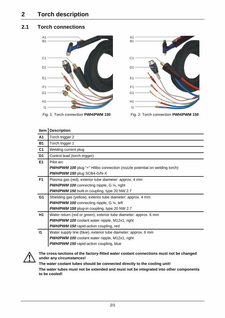
Item Description
A1 Torch trigger 2
B1 Torch trigger 1
C1 Welding current plug
D1 Control lead (torch trigger)
E1 Pilot arc
PWH/PWM 100 plug “+” Hilibo connection (nozzle potential on welding torch)
PWH/PWM 150 plug SCB4-G/N-X
F1 Plasma gas (red), exterior tube diameter: approx. 4 mm
PWH/PWM 100 connecting nipple, G ¼, right
PWH/PWM 150 built-in coupling, type 20 NW 2.7
G1 Shielding gas (yellow), exterior tube diameter: approx. 4 mm
PWH/PWM 100 connecting nipple, G ¼, left
PWH/PWM 150 plug-in coupling, type 20 NW 2.7
H1 Water return (red or green), exterior tube diameter: approx. 6 mm
PWH/PWM 100 coolant water nipple, M12x1, right
PWH/PWM 150 rapid-action coupling, red
I1 Water supply line (blue), exterior tube diameter: approx. 6 mm
PWH/PWM 100 coolant water nipple, M12x1, right
PWH/PWM 150 rapid-action coupling, blue
The cross-sections of the factory-fitted water coolant connections must not be changed under any circumstances!
The water coolant tubes should be connected directly to the cooling unit!
The water tubes must not be extended and must not be integrated into other components to be cooled!
2/1

2 Torch description
2.2 Torch layout
2.2.1 PWH/PWM 100
1
2
3
4
5
6
7
89
10
11
12
Figure 3 Torch layout PWH/PWM 100
Item Description
1 Clamping cap
2 O-ring
3 Collet casing
4 O-ring
5 Collet chuck
6 Electrode
7 Torch body
8 Gas nozzle seal
9 Gas supply insert
10 Plasma nozzle
11 Gas lens
12 Shielding gas nozzle
2/2

2 Torch description
2.2.2 PWH/PWM 150
18
4
6
7
89
10
11
12
Figure 4 Torch layout PWH/PWM 150
Item Description
18 Clamping cap
4 O-ring
6 Electrode
7 Torch body
8 Gas nozzle seal
9 Gas supply insert
10 Plasma nozzle
11 Gas lens
12 Shielding gas nozzle
2/3
2 Torch description
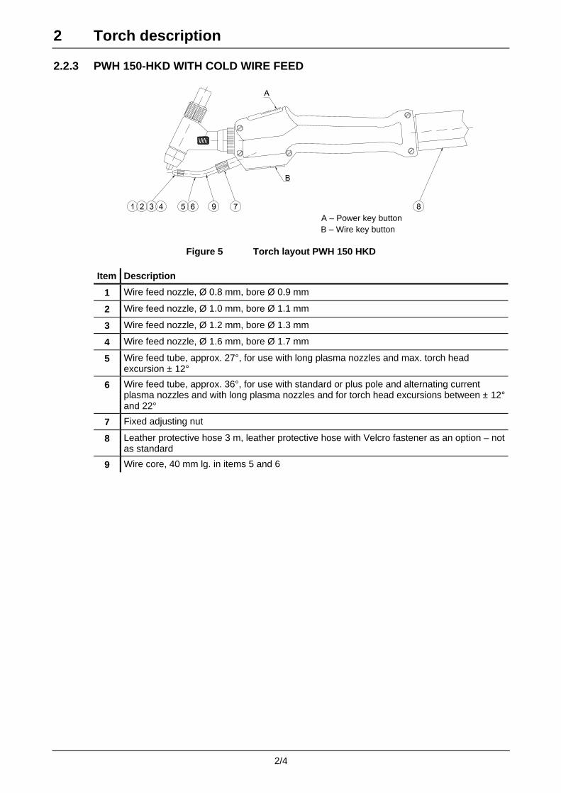
2.2.3 PWH 150-HKD WITH COLD WIRE FEED
A – Power key button
B – Wire key button
Figure 5 Torch layout PWH 150 HKD
Item Description
1 Wire feed nozzle, Ø 0.8 mm, bore Ø 0.9 mm
2 Wire feed nozzle, Ø 1.0 mm, bore Ø 1.1 mm
3 Wire feed nozzle, Ø 1.2 mm, bore Ø 1.3 mm
4 Wire feed nozzle, Ø 1.6 mm, bore Ø 1.7 mm
5 Wire feed tube, approx. 27°, for use with long plasma nozzles and max. torch head excursion ± 12°
6 Wire feed tube, approx. 36°, for use with standard or plus pole and alternating current plasma nozzles and with long plasma nozzles and for torch head excursions between ± 12° and 22°
7 Fixed adjusting nut
8 Leather protective hose 3 m, leather protective hose with Velcro fastener as an option – not as standard
9 Wire core, 40 mm lg. in items 5 and 6
2/4

2 Torch description
2.2.4 PWM 150-ROB 20° WITH COLD WIRE FEED
Figure 6 Torch layout PWM 150-ROB 20°
Item Description
24 Wire feed core
25 Wire core for wire feed tube
26 Support tube
27 Wire infeed nozzle, compl. with core
28 Cap, threaded sleeve
29 O-ring for gas connection
30 O-ring for water connection
31 Wire feed tube
2/5

2 Torch description
2.3 Torch components
2.3.1 Torch body The heat-dissipating conical surface in the torch head (figure 3 or 4, item 7) is used as the clamping surface and centring seat for the plasma nozzle (figure 2 or 3, item 10).
2.3.2 Plasma nozzles Shielding gas nozzle (figure 3 or 4, item 12) and gas lens (figure 3 or 4, item 11) are used as adjusting nut for the plasma nozzle.
The gas lens can be replaced if dirty or if required for the welding task.
The correct combination of gas lens and shielding gas nozzle achieves good shielding gas coverage, even at low gas quantities.
Standard, long and angle nozzles are available.
Thanks to the threadless nozzle holder, angle nozzles can be used in the torch in any position.
No corrections to the torch position following a nozzle change are required with angle nozzles without retaining thread.
2.3.3 Electrode seat in the PWH/PWM 100 The electrode (figure 3, item 6) is held by the draw-in collet (figure 3, item 5) in the collet casing (figure 3, item 3).
The position of the electrode can be adjusted by turning it on the collet casing.
For replacing the electrode, see chapter 2.5.1
2.3.4 Electrode seat in the PWH/PWM 150 The electrode (figure 4, item 6) is held in the clamping cap (figure 4, item 18).
For replacing the electrode, see chapter 2.6.1
2/6

2 Torch description
2.4 Torch cooling Part of the heat is conveyed via the plasma nozzle and gas lens to the cooling system (item 4) of the torch and part of the shielding gas (item 2) is blown out from the torch (item 5).
The electrode's large bearing surface has several advantages:
• Optimum cooling
• Optimum power transfer
• Long electrode service life
2
1
4
3
From 70 A, the cooling output of normal circulating cooling units can be too low.
This can damage the torch.
It may be necessary to use cooling units with a controlled supply line temperature.
The quality of the coolant should be checked at regular intervals (every three months at the latest). Deposits in the cooling unit, in the overall conduit system or in the torch have a negative effect on the cooling output.
The guarantee becomes void in the event of torch damage due to insufficient cooling and/or deposits in the cooling channels!
The torch is supplied in an uncooled power cable! With higher currents and long tube packages, the warming of the power cable can result in power restrictions. Where necessary, use torches with standard tube package lengths (3, max. 4 metres).
Check the power cable for heating. Use suitable measures where necessary!
2/7

2 Torch description
2.5 Disassembling and assembling the PWH/PWM 100
To disassemble or assemble the torch, switch off the power source or disconnect the torch from the power supply.
2.5.1 Replacing the electrode
2.5.1.1 Removing the electrode
• Unscrew the shielding gas nozzle (12).
• Remove the gas lens (11) from the shielding gas nozzle (12).
• Check the gas nozzle seal (8) for perfect condition. Replace if necessary.
The gas nozzle seal (8) need only be replaced if damaged, or for maintenance purposes!
• Remove the plasma nozzle (10) from the retainer cone in the torch head (7).
• Unfasten the nozzle from the retainer cone by turning it slightly (using pliers if necessary).
Never remove the nozzle by pulling it with force!!!
• Remove the gas supply insert (9) from the plasma nozzle (10).
• Loosen the clamping cap (1). Do not completely remove the clamping cap (1)!!
• Remove the electrode (6) from the torch.
7
1
6
9
11
10
12
8
Figure 1 Removing the electrode
2/8

2 Torch description
2.5.1.2 Installing the new electrode PWH/PWM 100
• Insert the new electrode (6) into the torch from the front.
• Tighten the clamping cap (1).
• Adjust the electrode position (see chap. 2.5.4).
• Check the gas lens (11), the retainer cone (7) and the plasma nozzle (10) for perfect condition, dirt and foreign bodies. Clean parts if necessary. Do not damage the cone during cleaning!
• Insert the gas lens (11) into the shielding gas nozzle (12).
• Ensure that the gas lens (11) is perfectly positioned! It should be still possible to move the gas lens!
• Push the gas supply insert (9) into the plasma nozzle (10).
Without a gas supply insert, the torch can be damaged on ignition!
• Insert the plasma nozzle (10) into the gas lens cone (11).
• Place the shielding gas nozzle (12) onto the electrode.
• Screw on the shielding gas nozzle (12) with the torch.
• Check the plasma nozzle (10) (using your fingers) for secure position in the torch.
7
1
6
9
11
10
12
8
Figure 2 Insert new electrode
2/9
2 Torch description
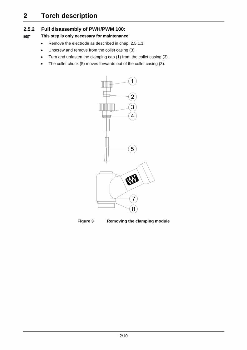
2.5.2 Full disassembly of PWH/PWM 100:
This step is only necessary for maintenance!
• Remove the electrode as described in chap. 2.5.1.1.
• Unscrew and remove from the collet casing (3).
• Turn and unfasten the clamping cap (1) from the collet casing (3).
• The collet chuck (5) moves forwards out of the collet casing (3).
78
Figure 3 Removing the clamping module
2/10

2 Torch description
2.5.3 Assembling the PWH/PWM 100: • Check that the surfaces of the O-rings (2+4) are in good condition.
Regrease or replace as necessary.
• Screw the clamping cap (1) into the collet casing (3). The column on the adjusting ring should be around 0 – 0.5 mm.
• Screw the collet chuck (5) into the clamping cap (1). The collet chuck should protrude approx. 0.5 - 1 mm from the slotted part of the collet casing (3).
• Screw the preassembled clamping module onto the torch (7). A gap of approx. 0.5 mm should remain between the clamping module and the torch head (7).
• Insert the electrode (6) into the collet chuck (5).
• Tighten the clamping cap (1) a little more. The collet chuck (5) is drawn into its casing and the electrode is held in the collet.
• Check that the electrode (6) can still be moved by hand.
• Adjust the electrode position (see chap. 2.5.4).
The collet chuck (5) must not rotate with the clamping cap (1) when it is turned!
If necessary, reassemble the clamping module.
78
0-0,5 mm
0,5 -1 mm
0,5 mm
6
Figure 4 Fitting the clamping module
2/11
2 Torch description
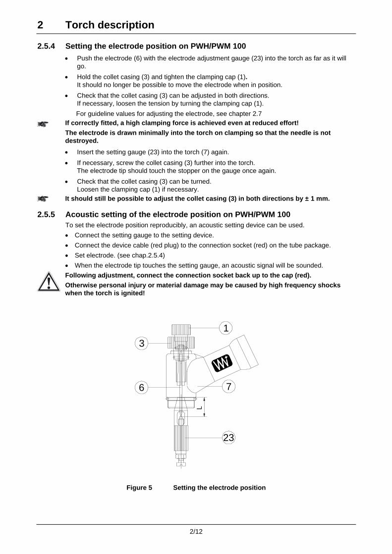
2.5.4 Setting the electrode position on PWH/PWM 100 • Push the electrode (6) with the electrode adjustment gauge (23) into the torch as far as it will
go.
• Hold the collet casing (3) and tighten the clamping cap (1). It should no longer be possible to move the electrode when in position.
• Check that the collet casing (3) can be adjusted in both directions. If necessary, loosen the tension by turning the clamping cap (1).
For guideline values for adjusting the electrode, see chapter 2.7
If correctly fitted, a high clamping force is achieved even at reduced effort!
The electrode is drawn minimally into the torch on clamping so that the needle is not destroyed.
• Insert the setting gauge (23) into the torch (7) again.
• If necessary, screw the collet casing (3) further into the torch. The electrode tip should touch the stopper on the gauge once again.
• Check that the collet casing (3) can be turned. Loosen the clamping cap (1) if necessary.
It should still be possible to adjust the collet casing (3) in both directions by ± 1 mm.
2.5.5 Acoustic setting of the electrode position on PWH/PWM 100 To set the electrode position reproducibly, an acoustic setting device can be used.
• Connect the setting gauge to the setting device.
• Connect the device cable (red plug) to the connection socket (red) on the tube package.
• Set electrode. (see chap.2.5.4)
• When the electrode tip touches the setting gauge, an acoustic signal will be sounded.
Following adjustment, connect the connection socket back up to the cap (red).
Otherwise personal injury or material damage may be caused by high frequency shocks when the torch is ignited!
6
3
7
23
1
L
Figure 5 Setting the electrode position
2/12

2 Torch description
2.6 Disassembling and assembling the PWH/PWM 150
To disassemble or assemble the torch, switch off the power source or disconnect the torch from the power supply.
2.6.1 Replacing the electrode
2.6.1.1 Removing the electrode
• Unscrew the shielding gas nozzle (12).
• Remove the gas lens (11) from the shielding gas nozzle (12).
• Check the gas nozzle seal (8) for perfect condition. Replace if necessary.
The gas nozzle seal (8) need only be replaced if damaged, or for maintenance purposes!
• Remove the plasma nozzle (10) from the retainer cone in the torch head (7).
• Unfasten the nozzle from the retainer cone by turning it slightly (using pliers if necessary).
Never remove the nozzle by pulling it with force!!!
• Remove the gas supply insert (9) from the plasma nozzle (10)
• Loosen the clamping cap (18).
• Remove the electrode from the torch.
18
8
9
10
11
12
7
Figure 6 Removing the electrode
2/13

2 Torch description 2.6.1.2 Installing the new electrode PWH/PWM 150
• Insert the new electrode (6) into the torch from the front.
• Tighten the clamping cap (18).
• Adjust the electrode position (see chap. 2.6.4).
• Check the gas lens (11), the retainer cone (7) and the plasma nozzle (10) for perfect condition, dirt and foreign bodies. Clean parts if necessary. Do not damage the cone during cleaning!
• Insert the gas lens (11) into the shielding gas nozzle (12).
• Ensure that the gas lens (11) is perfectly positioned! It should be still possible to move the gas lens!
• Push the gas supply insert (9) into the plasma nozzle (10).
Without a gas supply insert, the torch can be damaged on ignition!
• Insert the plasma nozzle (10) into the gas lens cone (11).
• Place the shielding gas nozzle (12) onto the electrode.
• Screw on the shielding gas nozzle with the torch.
• Check the plasma nozzle (10) (using your fingers) for secure position in the torch.
18
8
9
10
11
12
7
Figure 7 Insert new electrode
2/14
2 Torch description
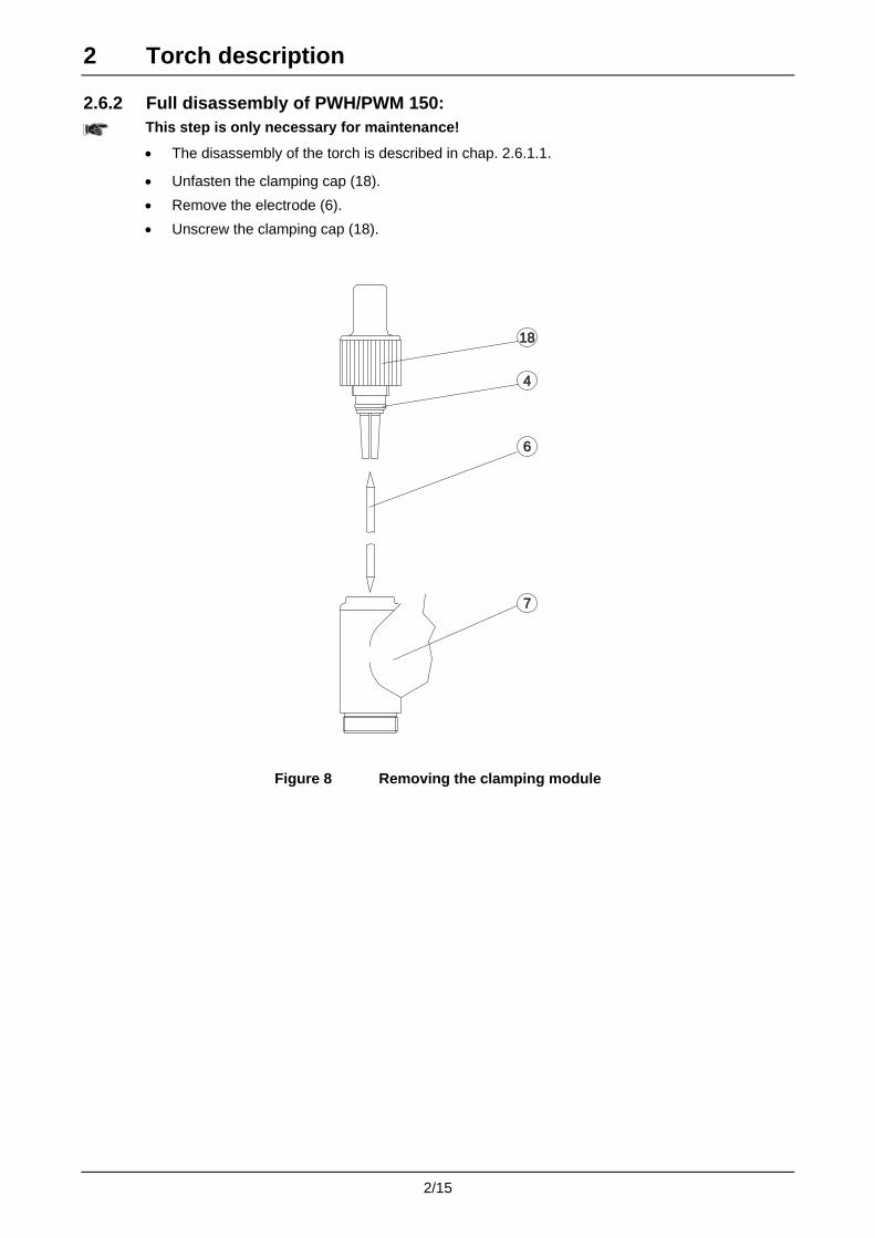
2.6.2 Full disassembly of PWH/PWM 150:
This step is only necessary for maintenance!
• The disassembly of the torch is described in chap. 2.6.1.1.
• Unfasten the clamping cap (18).
• Remove the electrode (6).
• Unscrew the clamping cap (18).
18
4
6
7
Figure 8 Removing the clamping module
2/15

2 Torch description
2.6.3 Assembling the PWH/PWM 150: • Check that the surfaces of the O-rings (4) are in good condition.
Regrease or replace as necessary.
• Screw in the clamping cap (18). Do not screw in fully!
• Insert the electrode (6) into the torch from the front.
• Tighten the clamping cap (18) until the electrode can still be moved, but no longer slips out.
• The setting of the electrode is described in chap. 2.6.4.
18
4
6
8
9
10
11
12
7
Figure 9 Fitting the clamping module
2/16
2 Torch description
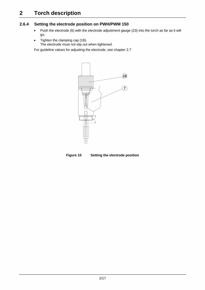
2.6.4 Setting the electrode position on PWH/PWM 150 • Push the electrode (6) with the electrode adjustment gauge (23) into the torch as far as it will
go.
• Tighten the clamping cap (18). The electrode must not slip out when tightened.
For guideline values for adjusting the electrode, see chapter 2.7
18
7
"L"
Figure 10 Setting the electrode position
2/17

2 Torch description
2.7 Setting values for the electrode position The correct position of the electrode affects the properties of the plasma stream and the ignition characteristics.
The following applies:
The greater the nozzle diameter, the smaller the "L" measurement.
With the same nozzle:
The greater the "L" measurement, the lower the nozzle loading.
2.7.1 Setting values with the electrode on the minus pole Measurement "L" is a guideline value. The optimum position is calculated by turning on the collet casing during operation.
"L" (ø5
,1)
Figure 11 Setting gauge
Nozzle type "L" measurement Nozzle diameter ( mm ) 0.5 0.6 0.8 1.0 1.2 1.4 1.6 1.8 2.0 2.2 2.4 2.6 3.0 3.2Standard 17 16 15.5 15 14.5 14 Long 21.5 20.5 20 19.5 19 Angle nozzle 16
2.7.2 Operation with plus pole of the electrode or alternating current Nozzle type "L" measurement for Nozzle diameter ( mm ) 1.2 1.6 2.0 2.4 Plus pole 15.5 15.3 15.1 15.1 After setting the electrode, load with 30-35 A briefly.
A semi-spherical tip will form.
Set the position of the electrode tip back to one of the values given above or to a value you have calculated yourself.
2/18

3 Commissioning
3.1 Proper usage The plasma welding torches PWH 100/150 and PWM 100/150 are intended only for commercial and industrial use by trained specialist staff. All technical conditions given in these operating instructions, and the relevant safety regulations, must be carefully studied and observed. In individual applications, e.g. in the case of particularly high heat reflection, additional measures may be required to prevent damage to the torch or faults. Recognising this and taking the correct remedial actions is the basic responsibility of the operator.
The torches may only be operated using original spare parts and replacement parts. The use of parts not approved by EWM will automatically void your guarantee!
No liability under the guarantee is accepted for damage caused by improper handling, insufficient cooling, overloading or lack of maintanence or incorrect maintenance work, and for replaceable parts.
3.2 Connection to the power source
A1B1
C1
D1
E1
F1
G1
H1
I1
A1B1
C1
D1
E1
F1
G1
H1
I1
Fig. 1: Torch connection PWH/PWM 100 Fig. 2: Torch connection PWH/PWM 150
PWH/PWM 100
• Screw on the plasma gas (red) F1 with connecting nipple G1/4 to the right
• Screw on the shielding gas (yellow) G1 with connecting nipple G1/4 to the left
• Screw on the water supply (blue) I1 and return (red or green) H1 with M12x1 connecting nipple
• Plug the Hilibo/plug E1 into the connection socket
• Plug control lead D1 into the connection socket
• Insert the welding current plug C1 into the socket and lock by turning to the right.
PWH/PWM 150
• Connect the plasma gas (red) F1 to plug-in nipple type 20 NW 2.7 and shielding gas (yellow) G1 to built-in coupling type 20 NW 2.7
• Connect water supply (blue) I1 to rapid-action coupling blue and water return (red) H1 to rapid-action coupling red
• Plug the Hilibo/plug E1 into the connection socket
• Plug control lead D1 into the connection socket
• Insert the welding current plug C1 into the socket and lock by turning to the right.
3/1

3 Commissioning
3.3 Welding mode
3.3.1 Preparations Allow the pilot gas to flow through the torch for a few minutes to blow out any accumulated air humidity. This prevents ignition problems.
The use of the special torch cap prevents air humidity penetration during longer pauses in work (overnight, weekend).
3.3.2 Start of welding The arc must stabilise briefly before welding.
The pilot arc does not burn centrally at this point.
Figure 1 Pilot arc
3.3.3 Setting the electrode Reset the electrode when starting a new welding task.
Set the arc optimally by turning the setting ring on the collet casing (3).
The position of the electrode can be transferred to the electrode gauge and reused each time for the same task.
3.3.4 Nozzle selection To achieve as long a nozzle service life as possible, the nozzle should not be loaded in excess of its maximum current. (see chap. 3.5)
If necessary, change to the next largest nozzle.
The nozzle service life is also affected by the plasma gas quantity used.
The following applies: The smaller the quantity of plasma gas, the shorter the service life.
As a guide, a 1 or 1.5 multiple of the nozzle diameter can be assumed as the distance between the plasma nozzle and the workpiece.
The shielding gas nozzle, Ø 12 mm has a good cleaning effect in aluminium welding.
Other nozzle types can also be tried out to optimise the cleaning effect.
3/2

3 Commissioning
3.3.5 Double arc At too great a current load or too slanted a torch position, a second arc forms between the workpiece and the plasma nozzle.
This results in considerable wear on the nozzle.
Figure 2 Double arc
3.3.6 Grinding the electrode The electrodes for plasma welding should be ground by machine. The electrode service life is extended and welding results are reproducible.
The grinding angle for minus pole welding is 30° (setting angle 15°).
The plus pole electrode, with a tip formed during operation in a sphere or semi-sphere, is pre-ground using an approx. 1 mm long chamfer at a chamfering angle of 45°. Its final form for welding operation is reached after brief loading in the upper power range (approx. 35 A)
The re-grinding lengths depend on the maximum current load.
The following applies: The lower an electrode’s actual current load in operation, the more often it can be reground.
The following guideline values apply to the torch:
Nozzle type Electrodes Ø Tip polishing Max. length Min. length Standard nozzle 1.5 mm 30°, both sides 51 mm 30 mm
Standard nozzle 2.4 mm 30°, one side 34 mm 27 mm
Angle nozzle 1.5 mm 30°, both sides 51 mm 30 mm Long plasma nozzle 1.5 mm 30°, both sides 54 mm 35 mm
Plus pole nozzle 3.2 mm One side, see above 30 mm 26 mm
3/3

3 Commissioning
3.4 Welding parameters
3.4.1 Main welding parameters • Welding current
• Plasma quantity
• Shielding gas
3.4.2 Plasma gas quantity The plasma gas quantities depend on the diameter of the plasma nozzle used.
Common values are at least 0.1 to approx. 1 l/min. These values apply to the following areas:
• Microplasma (up to approx. 20 A)
• Plasma joint welding and GMA-surfacing
The optimum plasma gas quantity must be calculated for the relevant welding task itself.
Higher quantities of plasma gas are required for keyhole welding.
Precise and reproducible quantity measurement must be ensured for the plasma gas quantity meter. In the event of deviations from the expected welding results, please note the actual gas quantity conveyed.
3.4.3 Keyhole welding Thanks to the high proportion of plasma gas (5 times or greater), the plasma stream is so intensive that it penetrates the workpiece and the weld seam behind the plasma stream is produced by the molten pool converging.
The advantages of the process:
• Narrow weld seams
• A high welding speed
• Low distortion of the components
• Thick walls in single layer welding.
3.4.4 Plasma gas selection Argon is normally used as the plasma gas.
3.4.5 Shielding gas quantity A good result is achieved with torches PWM100/PWH100 at a shielding gas quantity of just 2 - 5 litres per minute.
Various nozzles normally make it possible to ensure perfect shielding gas coverage for all welding tasks. In individual cases, additional shielding gas coverage may be necessary.
3.4.6 Shielding gas selection For most welding tasks Argon/hydrogen mixture (Ar + 4-6.5% H2)
For titanium and aluminimum materials Pure argon
Aluminium Helium and argon/helium gas mixtures
3/4
3 Commissioning
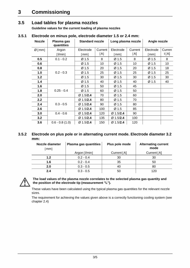
3.5 Load tables for plasma nozzles Guideline values for the current loading of plasma nozzles
3.5.1 Electrode on minus pole, electrode diameter 1.5 or 2.4 mm: Nozzle Plasma gas
quantities Standard nozzle Long plasma nozzle Angle nozzle
Ø [mm] Argon [l/min]
Electrode [mm]
Current [A]
Electrode [mm]
Current [A]
Electrode [mm]
Current [A]
0.5 Ø 1.5 8 Ø 1.5 8 Ø 1.5 8 0.6
0.1 - 0.2 Ø 1.5 10 Ø 1.5 10 Ø 1.5 10
0.8 Ø 1.5 20 Ø 1.5 20 Ø 1.5 18 1.0 Ø 1.5 25 Ø 1.5 25 Ø 1.5 25 1.2 Ø 1.5 30 Ø 1.5 30 Ø 1.5 30 1.4
0.2 - 0.3
Ø 1.5 40 Ø 1.5 40 Ø 1.5 40 1.6 Ø 1.5 50 Ø 1.5 45 1.8 Ø 1.5 60 Ø 1.5 50 2.0
0.25 - 0.4
Ø 1.5/2.4 70 Ø 1.5 60 2.2 Ø 1.5/2.4 80 Ø 1.5 70 2.4 Ø 1.5/2.4 90 Ø 1.5 80 2.6
0.3 - 0.5
Ø 1.5/2.4 100 Ø 1.5 85 3.0 Ø 1.5/2.4 120 Ø 1.5/2.4 90 3.2
0.4 - 0.6 Ø 1.5/2.4 135 Ø 1.5/2.4 100
3.6 0.6 - 0.8 (1.0) Ø 1.5/2.4 150 Ø 1.5/2.4 120
3.5.2 Electrode on plus pole or in alternating current mode. Electrode diameter 3.2 mm:
Plasma gas quantities Plus pole mode Alternating current mode
Nozzle diameter [mm]
Argon [l/min] Current [A] Current [A]
1.2 0.2 - 0.4 30 30 1.6 0.2 - 0.4 35 50 2.0 0.3 - 0.5 40 80 2.4 0.3 - 0.5 50 120
The load values of the plasma nozzle correlates to the selected plasma gas quantity and the position of the electrode tip (measurement "L").
These values have been calculated using the typical plasma gas quantities for the relevant nozzle sizes.
The requirement for achieving the values given above is a correctly functioning cooling system (see chapter 2.4)
3/5

4 Maintenance and repair
4.1 Maintenance work The following checks should be carried out reliably and thoroughly!
4.1.1 Daily maintenance tasks – with the power source switched off: • Check torch, tube package and power connections for exterior damage and replace if available
or have repaired by specialist staff!
• Check that all gas and water connections are securely sealed! Seal correctly, if necessary!
• Check that the cooling unit for the torch and the power source cooling (if necessary) are functioning correctly, and check the coolant level! If required, top up with demineralised water or with the prescribed coolant! If necessary, have repairs carried out!
• Check the replaceable parts in the torch, including the gas lens and gas nozzle seal!
• For torches with integrated cold wire feed: Check the cold wire supply nozzle and adjusting nut on the cold wire supply tube!
4.1.2 Monthly maintenance tasks – with the power source switched off: • Check for filter impurities in the coolant system!
Replace if necessary! Do not clean the filter insert; replace it!
• If no filter is fitted: Check the coolant container for sludge deposits and check the coolant for cloudiness. Clean the coolant container if contaminated, and replace the coolant! Observe the prescribed coolant quality!
• Check the electrical conductivity of the coolant! If conductive, replace the coolant!
• If the coolant is dirty, rinse through the torch alternately several times using the coolant return and supply to remove all deposits from the torch.
• Disassemble and check the plasma welding torch and the electrode clamping module. Clean if necessary! Deposits in the torch can cause high frequency shocks and thus cause damage to the torch!
• Check the O-rings in the clamping cap and in the collet casing! Replace if necessary! Grease the O-rings with silicone grease or Vaseline!
• Check the O-rings on the gas and water nipples on the robot torch! Replace if necessary! Grease the O-rings with silicone grease or Vaseline!
4.2 Repairs If damage occurs to the torch or to the tube package which cannot be corrected as part of the maintenance work, the entire torch must be returned to the manufacturer.
Repairs to the tube package and torch connections may only be carried out by authorised specialist staff!
Do not remove the torch from the tube package!
Do not clamp the torch head in a vice or similar!
This could destroy the torch beyond repair.
4/1
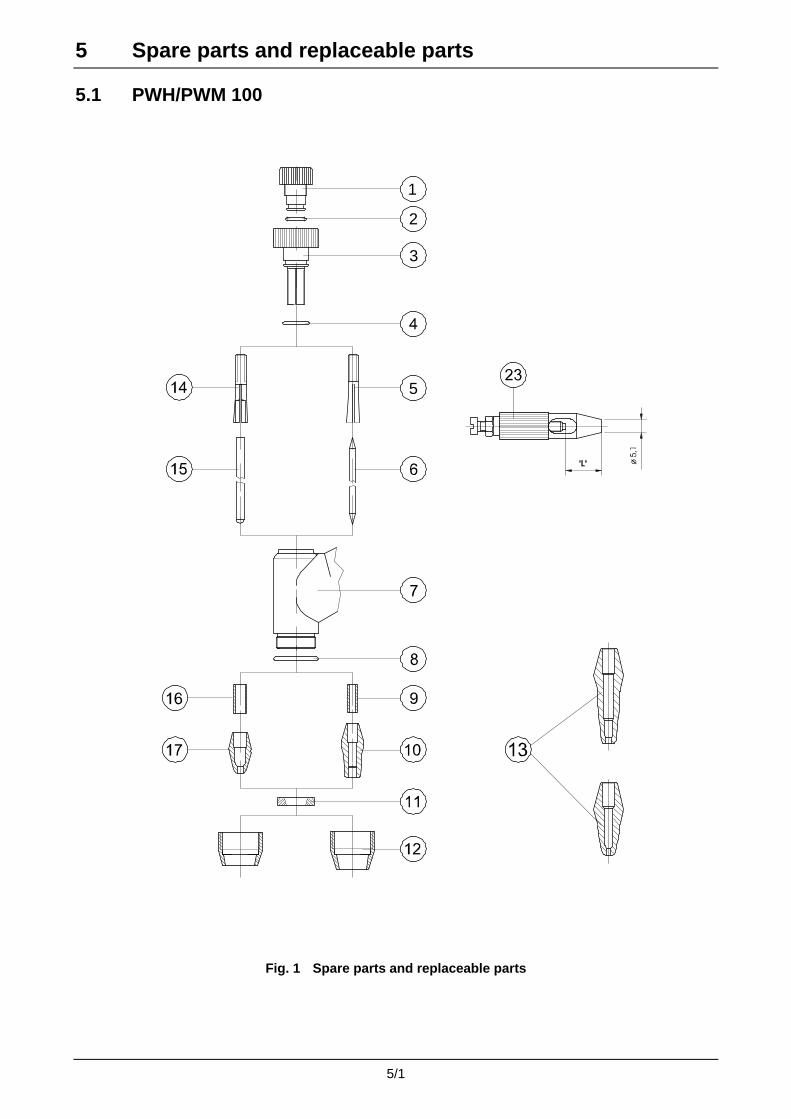
5 Spare parts and replaceable parts
5.1 PWH/PWM 100
1
2
3
5
Fig. 1 Spare parts and replaceable parts
5/1

5 Spare parts and replaceable parts
Item Designation Type Item number 1. Clamping cap, cpl. - 094-008274-00000
2. O-ring O-RING TORCH CAP 094-008233-00000
3. Collet casing, cpl. - 094-008276-00000
4. O-ring O-RING RETAINER 094-008234-00000
5. Collet chuck COLLET 1.5 094-008235-00000
Collet chuck COLLET 2.4 094-008277-00000
6. Tungsten electrode, special TUNGSTEN SPEC D1.5 094-008951-00000
Tungsten electrode, special TUNGSTEN SPEC D2.4 094-008789-00000
Tungsten electrode, special TUNGSTEN SPEC D3.2 094-008952-00000
7. Torch body -
8. Gas nozzle seal SFN DUE 094-008236-00000
9. Gas supply insert TUBE D1.5MM 094-008241-00000
Gas supply insert TUBE D2.4MM 094-008787-00000
10. Plasma nozzle PNOZZ 0.5MM 8A 094-009392-00000
Plasma nozzle PNOZZ 0.6MM 10A 094-008282-00000
Plasma nozzle PNOZZ 0.8MM 20A 094-008243-00000
Plasma nozzle PNOZZ 1.0MM 25A 094-008244-00000
Plasma nozzle PNOZZ 1.2MM 30A 094-008245-00000
Plasma nozzle PNOZZ 1.4MM 40A 094-008246-00000
Plasma nozzle PNOZZ 1.6MM 50A 094-008247-00000
Plasma nozzle PNOZZ 1.8MM 60A 094-008248-00000
Plasma nozzle PNOZZ 2.0MM 70A 094-008249-00000
Plasma nozzle PNOZZ 2.2MM 80A 094-009393-00000
Plasma nozzle PNOZZ 2.4MM 90A 094-008250-00000
Plasma nozzle PNOZZ 2.6MM 100A 094-009394-00000
Plasma nozzle PNOZZ 3.0MM 120A 094-008251-00000
11. Gas lens, fine-pored GASL 094-008242-00000
Gas lens, large-pored GASL 094-008281-00000
12. Shielding gas nozzle, short GASNOZZ SHORT D11MM 094-008237-00000
Shielding gas nozzle, short GASNOZZ SHORT D12MM 094-008238-00000
Shielding gas nozzle, long GASNOZZ LONG D11MM 094-008239-00000
Shielding gas nozzle, long GASNOZZ LONG D9.5MM 094-008240-00000
13. Plasma nozzle, long PNOZZ LONG 0.5MM 8A 094-009396-00000
Plasma nozzle, long PNOZZ LONG 0.6MM 10A 094-009397-00000
Plasma nozzle, long PNOZZ LONG 0.8MM 20A 094-008252-00000
Plasma nozzle, long PNOZZ LONG 1.0MM 25A 094-008253-00000
Plasma nozzle, long PNOZZ LONG 1.2MM 30A 094-008254-00000
Plasma nozzle, long PNOZZ LONG 1.4MM 40A 094-008255-00000
Plasma nozzle, long PNOZZ LONG 1.6MM 45A 094-008256-00000
Plasma nozzle, long PNOZZ LONG 1.8MM 50A 094-008257-00000
Plasma nozzle, long PNOZZ LONG 2.0MM 60A 094-008258-00000
Plasma nozzle, long PNOZZ LONG 2.2MM 70A 094-008550-00000
Plasma nozzle, long PNOZZ LONG 2.4MM 80A 094-008259-00000
Plasma nozzle, long PNOZZ LONG 2.6MM 85A 094-008551-00000
Plasma nozzle, long PNOZZ LONG 3.0MM 90A 094-008260-00000
14. Collet chuck, plus pole COLLET 3.2 094-008278-00000
15. Tungsten electrode, special TUNGSTEN SPEC D3.2 094-008268-00000
Tungsten electrode, special TUNGSTEN SPEC D3.2 094-008953-00000
16. Gas supply insert, plus pole TUBE D3.2MM 094-008280-00000
17. Plasma nozzle, plus pole PNOZZ PLUSPOL AC 1.2MM 094-008264-00000
Plasma nozzle, plus pole PNOZZ PLUSPOL AC 1.6MM 094-008265-00000
Plasma nozzle, plus pole PNOZZ PLUSPOL AC 2.0MM 094-008266-00000
Plasma nozzle, plus pole PNOZZ PLUSPOL AC 2.4MM 094-008267-00000
23. Electrode adjustment gauge ELECTRODE ADJUSTMENT GAUGE 094-008262-00000
5/2

5 Spare parts and replaceable parts
5.2 PWH/PWM 150
Fig. 2 Spare parts and replaceable parts
5/3

5 Spare parts and replaceable parts Designation Type Item number 4. O-ring O-RING RETAINER 094-008234-00000
6. Tungsten electrode, special TUNGSTEN SPEC D1.5 094-008251-00000
Tungsten electrode, special TUNGSTEN SPEC D2.4 094-008789-00000
Tungsten electrode, special TUNGSTEN SPEC D3.2 094-008952-00000
7. Torch body -
8. Gas nozzle seal SFN DUE 094-008236-00000
9. Gas supply insert TUBE D1.5MM 094-008241-00000
Gas supply insert TUBE D2.4MM 094-008787-00000
10. Plasma nozzle PNOZZ 0.5MM 8A 094-009392-00000
Plasma nozzle PNOZZ 0.6MM 10A 094-008282-00000
Plasma nozzle PNOZZ 0.8MM 20A 094-008243-00000
Plasma nozzle PNOZZ 1.0MM 25A 094-008244-00000
Plasma nozzle PNOZZ 1.2MM 30A 094-008245-00000
Plasma nozzle PNOZZ 1.4MM 40A 094-008246-00000
Plasma nozzle PNOZZ 1.6MM 50A 094-008247-00000
Plasma nozzle PNOZZ 1.8MM 60A 094-008248-00000
Plasma nozzle PNOZZ 2.0MM 70A 094-008249-00000
Plasma nozzle PNOZZ 2.2MM 80A 094-009393-00000
Plasma nozzle PNOZZ 2.4MM 90A 094-008250-00000
Plasma nozzle PNOZZ 2.6MM 100A 094-009394-00000
Plasma nozzle PNOZZ 3.0MM 120A 094-008251-00000
Plasma nozzle PNOZZ 3.2MM 135A 094-009126-00000
Plasma nozzle PNOZZ 3.6MM 150A 094-009395-00000
11. Gas lens, large-pored GASL 094-008281-00000
Gas lens, fine-pored GASL 094-008242-00000
12. Shielding gas nozzle, short GASNOZZ SHORT D11MM 094-008237-00000
Shielding gas nozzle, short GASNOZZ SHORT D12MM 094-008238-00000
Shielding gas nozzle, long GASNOZZ LONG D11MM 094-008239-00000
Shielding gas nozzle, long GASNOZZ LONG D9.5MM 094-008240-00000
13. Plasma nozzle, long PNOZZ LONG 0.5MM 8A 094-009396-00000
Plasma nozzle, long PNOZZ LONG 0.6MM 10A 094-009397-00000
Plasma nozzle, long PNOZZ LONG 0.8MM 20A 094-008252-00000
Plasma nozzle, long PNOZZ LONG 1.0MM 25A 094-008253-00000
Plasma nozzle, long PNOZZ LONG 1.2MM 30A 094-008254-00000
Plasma nozzle, long PNOZZ LONG 1.4MM 40A 094-008255-00000
Plasma nozzle, long PNOZZ LONG 1.6MM 45A 094-008256-00000
Plasma nozzle, long PNOZZ LONG 1.8MM 50A 094-008257-00000
Plasma nozzle, long PNOZZ LONG 2.0MM 60A 094-008258-00000
Plasma nozzle, long PNOZZ LONG 2.2MM 70A 094-008550-00000
Plasma nozzle, long PNOZZ LONG 2.4MM 80A 094-008259-00000
Plasma nozzle, long PNOZZ LONG 2.6MM 85A 094-008551-00000
Plasma nozzle, long PNOZZ LONG 3.0MM 90A 094-008260-00000
Plasma nozzle, long PNOZZ LONG 3.2MM 100A 094-008479-00000
Plasma nozzle, long PNOZZ LONG 3.6MM 120A 094-008788-00000
15. Tungsten electrode, special TUNGSTEN SPEC D3.2 094-008268-00000
Tungsten electrode, special TUNGSTEN SPEC D3.2 094-008953-00000
16. Gas supply insert, plus pole TUBE D3.2MM 094-008280-00000
17. Plasma nozzle, plus pole PNOZZ PLUSPOL AC 1.2MM 094-008264-00000
Plasma nozzle, plus pole PNOZZ PLUSPOL AC 1.6MM 094-008265-00000
Plasma nozzle, plus pole PNOZZ PLUSPOL AC 2.0MM 094-008266-00000
Plasma nozzle, plus pole PNOZZ PLUSPOL AC 2.4MM 094-008267-00000
18. Clamping module for electrode 1.5 mm 094-008557-00000
Clamping module for electrode 2.4 mm 094-009398-00000
Clamping module for electrode 3.2 mm 094-009399-00000
23. Electrode adjustment gauge ELECTRODE ADJUSTMENT GAUGE 094-008262-00000
5/4

5 Spare parts and replaceable parts
5.3 PWH 150 HKD with cold wire feed
Fig. 3 Spare parts and replaceable parts
5/5
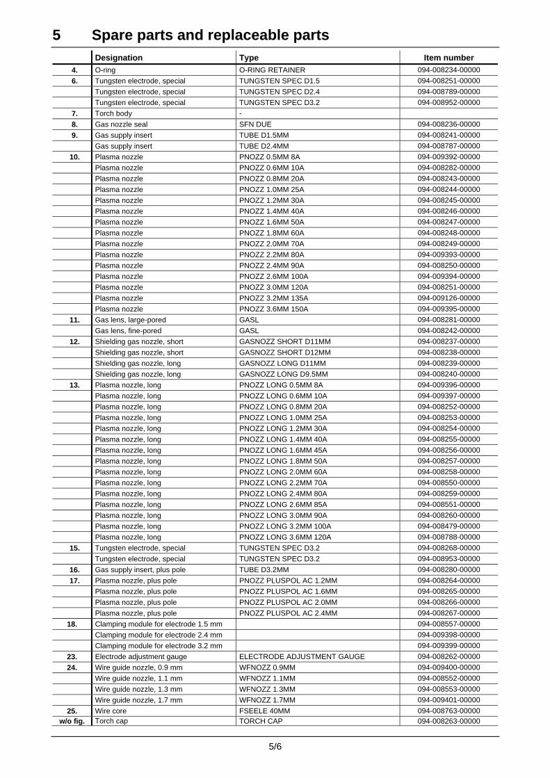
5 Spare parts and replaceable parts Designation Type Item number 4. O-ring O-RING RETAINER 094-008234-00000
6. Tungsten electrode, special TUNGSTEN SPEC D1.5 094-008251-00000
Tungsten electrode, special TUNGSTEN SPEC D2.4 094-008789-00000
Tungsten electrode, special TUNGSTEN SPEC D3.2 094-008952-00000
7. Torch body -
8. Gas nozzle seal SFN DUE 094-008236-00000
9. Gas supply insert TUBE D1.5MM 094-008241-00000
Gas supply insert TUBE D2.4MM 094-008787-00000
10. Plasma nozzle PNOZZ 0.5MM 8A 094-009392-00000
Plasma nozzle PNOZZ 0.6MM 10A 094-008282-00000
Plasma nozzle PNOZZ 0.8MM 20A 094-008243-00000
Plasma nozzle PNOZZ 1.0MM 25A 094-008244-00000
Plasma nozzle PNOZZ 1.2MM 30A 094-008245-00000
Plasma nozzle PNOZZ 1.4MM 40A 094-008246-00000
Plasma nozzle PNOZZ 1.6MM 50A 094-008247-00000
Plasma nozzle PNOZZ 1.8MM 60A 094-008248-00000
Plasma nozzle PNOZZ 2.0MM 70A 094-008249-00000
Plasma nozzle PNOZZ 2.2MM 80A 094-009393-00000
Plasma nozzle PNOZZ 2.4MM 90A 094-008250-00000
Plasma nozzle PNOZZ 2.6MM 100A 094-009394-00000
Plasma nozzle PNOZZ 3.0MM 120A 094-008251-00000
Plasma nozzle PNOZZ 3.2MM 135A 094-009126-00000
Plasma nozzle PNOZZ 3.6MM 150A 094-009395-00000
11. Gas lens, large-pored GASL 094-008281-00000
Gas lens, fine-pored GASL 094-008242-00000
12. Shielding gas nozzle, short GASNOZZ SHORT D11MM 094-008237-00000
Shielding gas nozzle, short GASNOZZ SHORT D12MM 094-008238-00000
Shielding gas nozzle, long GASNOZZ LONG D11MM 094-008239-00000
Shielding gas nozzle, long GASNOZZ LONG D9.5MM 094-008240-00000
13. Plasma nozzle, long PNOZZ LONG 0.5MM 8A 094-009396-00000
Plasma nozzle, long PNOZZ LONG 0.6MM 10A 094-009397-00000
Plasma nozzle, long PNOZZ LONG 0.8MM 20A 094-008252-00000
Plasma nozzle, long PNOZZ LONG 1.0MM 25A 094-008253-00000
Plasma nozzle, long PNOZZ LONG 1.2MM 30A 094-008254-00000
Plasma nozzle, long PNOZZ LONG 1.4MM 40A 094-008255-00000
Plasma nozzle, long PNOZZ LONG 1.6MM 45A 094-008256-00000
Plasma nozzle, long PNOZZ LONG 1.8MM 50A 094-008257-00000
Plasma nozzle, long PNOZZ LONG 2.0MM 60A 094-008258-00000
Plasma nozzle, long PNOZZ LONG 2.2MM 70A 094-008550-00000
Plasma nozzle, long PNOZZ LONG 2.4MM 80A 094-008259-00000
Plasma nozzle, long PNOZZ LONG 2.6MM 85A 094-008551-00000
Plasma nozzle, long PNOZZ LONG 3.0MM 90A 094-008260-00000
Plasma nozzle, long PNOZZ LONG 3.2MM 100A 094-008479-00000
Plasma nozzle, long PNOZZ LONG 3.6MM 120A 094-008788-00000
15. Tungsten electrode, special TUNGSTEN SPEC D3.2 094-008268-00000
Tungsten electrode, special TUNGSTEN SPEC D3.2 094-008953-00000
16. Gas supply insert, plus pole TUBE D3.2MM 094-008280-00000
17. Plasma nozzle, plus pole PNOZZ PLUSPOL AC 1.2MM 094-008264-00000
Plasma nozzle, plus pole PNOZZ PLUSPOL AC 1.6MM 094-008265-00000
Plasma nozzle, plus pole PNOZZ PLUSPOL AC 2.0MM 094-008266-00000
Plasma nozzle, plus pole PNOZZ PLUSPOL AC 2.4MM 094-008267-00000
18. Clamping module for electrode 1.5 mm 094-008557-00000
Clamping module for electrode 2.4 mm 094-009398-00000
Clamping module for electrode 3.2 mm 094-009399-00000
23. Electrode adjustment gauge ELECTRODE ADJUSTMENT GAUGE 094-008262-00000
24. Wire guide nozzle, 0.9 mm WFNOZZ 0.9MM 094-009400-00000
Wire guide nozzle, 1.1 mm WFNOZZ 1.1MM 094-008552-00000
Wire guide nozzle, 1.3 mm WFNOZZ 1.3MM 094-008553-00000
Wire guide nozzle, 1.7 mm WFNOZZ 1.7MM 094-009401-00000
25. Wire core FSEELE 40MM 094-008763-00000 w/o fig. Torch cap TORCH CAP 094-008263-00000
5/6

5 Spare parts and replaceable parts
5.4 PWM 150-ROB 20° with cold wire feed
Fig. 4 Spare parts and replaceable parts
5/7

5 Spare parts and replaceable parts Designation Type Item number 4. O-ring O-RING RETAINER 094-008234-00000
6. Tungsten electrode, special TUNGSTEN SPEC D1.5 094-008251-00000
Tungsten electrode, special TUNGSTEN SPEC D2.4 094-008789-00000
Tungsten electrode, special TUNGSTEN SPEC D3.2 094-008952-00000
7. Torch body -
8. Gas nozzle seal SFN DUE 094-008236-00000
9. Gas supply insert TUBE D1.5MM 094-008241-00000
Gas supply insert TUBE D2.4MM 094-008787-00000
10. Plasma nozzle PNOZZ 0.5MM 8A 094-009392-00000
Plasma nozzle PNOZZ 0.6MM 10A 094-008282-00000
Plasma nozzle PNOZZ 0.8MM 20A 094-008243-00000
Plasma nozzle PNOZZ 1.0MM 25A 094-008244-00000
Plasma nozzle PNOZZ 1.2MM 30A 094-008245-00000
Plasma nozzle PNOZZ 1.4MM 40A 094-008246-00000
Plasma nozzle PNOZZ 1.6MM 50A 094-008247-00000
Plasma nozzle PNOZZ 1.8MM 60A 094-008248-00000
Plasma nozzle PNOZZ 2.0MM 70A 094-008249-00000
Plasma nozzle PNOZZ 2.2MM 80A 094-009393-00000
Plasma nozzle PNOZZ 2.4MM 90A 094-008250-00000
Plasma nozzle PNOZZ 2.6MM 100A 094-009394-00000
Plasma nozzle PNOZZ 3.0MM 120A 094-008251-00000
Plasma nozzle PNOZZ 3.2MM 135A 094-009126-00000
Plasma nozzle PNOZZ 3.6MM 150A 094-009395-00000
11. Gas lens, large-pored GASL 094-008281-00000
Gas lens, fine-pored GASL 094-008242-00000
12. Shielding gas nozzle, short GASNOZZ SHORT D11MM 094-008237-00000
Shielding gas nozzle, short GASNOZZ SHORT D12MM 094-008238-00000
Shielding gas nozzle, long GASNOZZ LONG D11MM 094-008239-00000
Shielding gas nozzle, long GASNOZZ LONG D9.5MM 094-008240-00000
13. Plasma nozzle, long PNOZZ LONG 0.5MM 8A 094-009396-00000
Plasma nozzle, long PNOZZ LONG 0.6MM 10A 094-009397-00000
Plasma nozzle, long PNOZZ LONG 0.8MM 20A 094-008252-00000
Plasma nozzle, long PNOZZ LONG 1.0MM 25A 094-008253-00000
Plasma nozzle, long PNOZZ LONG 1.2MM 30A 094-008254-00000
Plasma nozzle, long PNOZZ LONG 1.4MM 40A 094-008255-00000
Plasma nozzle, long PNOZZ LONG 1.6MM 45A 094-008256-00000
Plasma nozzle, long PNOZZ LONG 1.8MM 50A 094-008257-00000
Plasma nozzle, long PNOZZ LONG 2.0MM 60A 094-008258-00000
Plasma nozzle, long PNOZZ LONG 2.2MM 70A 094-008550-00000
Plasma nozzle, long PNOZZ LONG 2.4MM 80A 094-008259-00000
Plasma nozzle, long PNOZZ LONG 2.6MM 85A 094-008551-00000
Plasma nozzle, long PNOZZ LONG 3.0MM 90A 094-008260-00000
Plasma nozzle, long PNOZZ LONG 3.2MM 100A 094-008479-00000
Plasma nozzle, long PNOZZ LONG 3.6MM 120A 094-008788-00000
15. Tungsten electrode, special TUNGSTEN SPEC D3.2 094-008268-00000
Tungsten electrode, special TUNGSTEN SPEC D3.2 094-008953-00000
16. Gas supply insert, plus pole TUBE D3.2MM 094-008280-00000
17. Plasma nozzle, plus pole PNOZZ PLUSPOL AC 1.2MM 094-008264-00000
Plasma nozzle, plus pole PNOZZ PLUSPOL AC 1.6MM 094-008265-00000
Plasma nozzle, plus pole PNOZZ PLUSPOL AC 2.0MM 094-008266-00000
Plasma nozzle, plus pole PNOZZ PLUSPOL AC 2.4MM 094-008267-00000
18. Clamping module for electrode 1.5 mm 094-008557-00000
Clamping module for electrode 2.4 mm 094-009398-00000
Clamping module for electrode 3.2 mm 094-009399-00000
23. Electrode adjustment gauge ELECTRODE ADJUSTMENT GAUGE 094-008262-00000
24. Wire guide nozzle, 0.9 mm WFNOZZ 0.9MM 094-009400-00000
Wire guide nozzle, 1.1 mm WFNOZZ 1.1MM 094-008552-00000
Wire guide nozzle, 1.3 mm WFNOZZ 1.3MM 094-008553-00000
Wire guide nozzle, 1.7 mm WFNOZZ 1.7MM 094-009401-00000
25. Wire core FSEELE 40MM 094-008763-00000
5/8
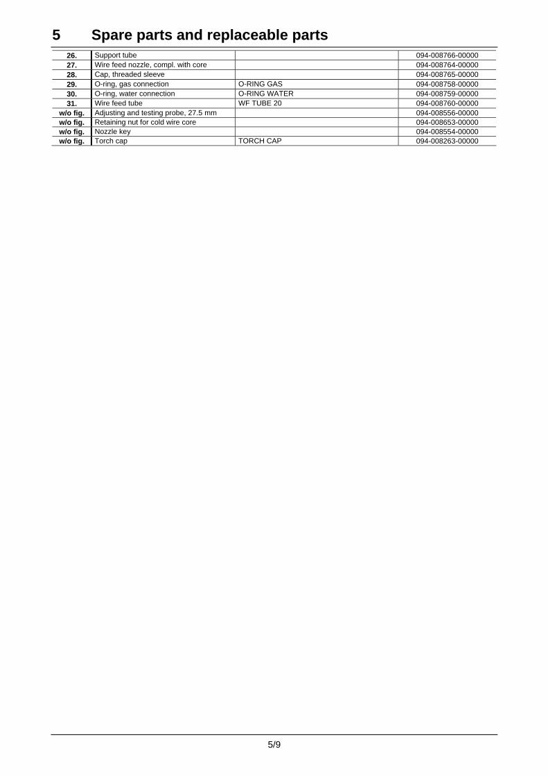
5 Spare parts and replaceable parts 26. Support tube 094-008766-00000 27. Wire feed nozzle, compl. with core 094-008764-00000 28. Cap, threaded sleeve 094-008765-00000 29. O-ring, gas connection O-RING GAS 094-008758-00000 30. O-ring, water connection O-RING WATER 094-008759-00000 31. Wire feed tube WF TUBE 20 094-008760-00000
w/o fig. Adjusting and testing probe, 27.5 mm 094-008556-00000 w/o fig. Retaining nut for cold wire core 094-008653-00000 w/o fig. Nozzle key 094-008554-00000 w/o fig. Torch cap TORCH CAP 094-008263-00000
5/9