gbppr 'zine - pdf.textfiles.compdf.textfiles.com/zines/gbppr/gbppr_zine_12.pdf · gbppr...
TRANSCRIPT

GBPPR 'Zine
Issue #12 / The Monthly Journal of the American Hacker / March 2005
"I'm a great believer in luck, and I find that the harder I work, the more I have of it." − Thomas Jefferson (1743 − 1826)
"Thinking is the hardest work there is, which is probably why so few engage in it." − Henry Ford (1863 − 1947)
"I dried it in a toaster oven and hid it from your mother. I put in a Ziplock bag andsold it to your brother." − Beastie Boys, Car Thief Demo
Table of Contents
Page 2 / Nortel DMS−100 Log Report Information♦ Information on the DMS−100 log reporting system and its subsystems.♦
Page 51 / Nortel DMS−100 Security Log Reports♦ Detailed information on log reports related to DMS−100 system security.♦
Page 87 / Nortel DMS−100 Table DNINV♦ How to list all the directory numbers on a DMS−100 switch.♦
Page 91 / Nortel DMS−100 Table TOFCNAME♦ How to list all the sekret exchanges on a DMS−100 switch.♦
Page 95 / Manhole Covers − Removing & Replacing♦ How to remove Bell System manhole covers.♦
Page 114 / Rescue of Employee from Manhole♦ Oh Shit!♦
Page 119 / Mosque Time−Lapse Surveillance Camera♦ Monitor those bastards.♦
Page 127 / Bonus♦ Old SARTS/SMAS note.♦
Page 128 / The End♦ Editorial and Rants.♦
Page 130 / ERROR!♦
1

Nortel DMS−100 Log Report InformationUnderstanding Log Reports
A log report is a message. The DMS−100 switch generates a log report when an important eventoccurs in the switch or one of its peripherals. Log reports include the following information:
State and activity reports.• Reports on hardware or software errors.• Test results.• Changes in state.• Other events or conditions that affect the performance of the switch.•
A log report appears in response to either a system or a manual action.
Controlling Output from the Log System
Log output includes storage, distribution, prioritization, suppression, and thresholds. There are twoforms of log output control. First, each office changes the appropriate Customer Data tables tocustomize the output from the log system to meet local requirements. Second, Log Utility(LOGUTIL) commands can be executed in the LOGUTIL level of the MAP display. The use ofLOGUTIL commands can temporarily override parameters set in the Customer Data tables. Forexample, commands can override parameters to turn log reports off, or to route output temporarilyto a different device.
In most conditions, a restart will reset any temporary change made through LOGUTILcommands. A restart is a reinitialization of the DMS−100 operating system and userprocesses. Refer to the temporary Routing Commands section of the "Output Control Software"chapter of the Input/Output System Reference Manual.
Log Buffers
Each log buffer holds several hours of subsystem reports at peak output rates. The value of theoffice parameter LOG_CENTRAL_BUFFER_SIZE in table OFCVAR determines the number ofreports the log buffers held. Refer to the OFCVAR parameters section in the Office ParametersReference Manual.
Log buffers store the output reports in the order that they are generated. A Central MessageController (CMC) report that generates at 16:04:39 appears in the log buffer before a report thatgenerates at 16:08:33. When a subsystem buffer is full, the next report that generates displaces theoldest report. Unless the displaced log report is routed to some type of external storage device, thelog report is lost. The user cannot retrieve the log report.
The Critical Message Prioritization feature provides an additional method to define the order logreports are output to a specified log device. This office parameter LOG_PRIORITIZATION in tableOFCENG activates or deactivates the feature. Refer to the OFCENG parameters section in theOffice Parameters Reference Manual.
Active log report alarm levels categorize log reports. The log report alarm levels are Critical, Major,Minor, No Alarm. The reports are output to specified devices in order of most critical to least criticalalarm. The log buffer stores reports of the same alarm category in order.
2

Routing Log Reports
In addition to storing the reports, the output reporting system can route the reports to devices whichthe operating company defines. Devices which the operating company defines include MTD, DDU,Data Link, Printer, and VDU.
Each device has a buffer area, which under normal conditions can handle a large number of logreports. If devices lose reports that the system indicates, increase the size of the log buffer. Toincrease the size of the log buffer, change the office parameter LOG_DEVICE_BUFFER_SIZE intable OFCVAR. Refer to the OFCVAR parameters section in the Office Parameters ReferenceManual.
Routing and Reporting Subsystems
The routing and reporting subsystem routes reports from the log system buffers to an I/Odevice. The I/O device prints, displays, or stores the reports. Data tables LOGCLASS and LGDEVcontrol the subsystem and provide basic permanent routing.
To route a log report to a device, the following units of information must be available to theDMS−100 switch. Table LOGCLASS defines the class number of the report to be routed. TableLOGDEV defines the device(s) that are to receive the class number of log reports.
The following table displays the assignment of class numbers to the CMC log reports. When theCMC subsystem generates a log report, the routing and reporting subsystem references tableLOGCLASS. The routing and reporting subsystem discovers the log report is class 4. When theclass number is available, table LOGDEV searches for the device(s) which table LOGDEV definesto receive class 4 reports. In this example, the device is PRT1. The routing and reportingsubsystem transmits the report through the log device buffer for PRT1 to the accurate device.
−−−−−−−−−−−−−−−−−−−−−−−−−−−−−−−−−−−−−−−−−−−−−−−−−−−−−−−−−−−−−−−−−−−−−−−−−−−−−−−−−−−−−−−−−REPORTS CLASS DEVICE
−−−−−−−−−−−−−−−−−−−−−−−−−−−−−−−−−−−−−−−−−−−−−−−−−−−−−−−−−−−−−−−−−−−−−−−−−−−−−−−−−−−−−−−−−GROUP 1 NET 121 24 PRT1GROUP 2 NET 115 24 PRT2GROUP 3 PM 105 24 PRT3GROUP 4 CMC 105 4 PRT1GROUP 5 LINE 108 24 PRT2GROUP 6 TRK 151 24 PRT3−−−−−−−−−−−−−−−−−−−−−−−−−−−−−−−−−−−−−−−−−−−−−−−−−−−−−−−−−−−−−−−−−−−−−−−−−−−−−−−−−−−−−−−−−
LOGUTIL Commands
The LOGUTIL commands allow the user to perform the following functions:
Obtain information that concerns log reports, I/O devices, and thresholds.• Start and stop devices from receiving log reports.• Browse through log subsystem buffers.• Erase reports to clear log subsystem buffers.• Establish temporary routing commands that override the permanent routing entries in tables LOGCLASS andLOGDEV. The permanent entries in these tables do not change and remain available to reverse conversionback to permanent routing.
•
An example of temporary routing is an I/O device which malfunctions. The I/O device and theassociated log reports must be routed to another device. Operating company personnel requiretemporary routing to route log reports to a Video Display Unit (VDU) for troubleshooting purposes.
3

Tables
The following tables appear in this document. The tables list log header descriptions, logsubsystems, event types, information−only logs, trouble codes, reason codes, equipment states,and call types. The tables also list other information. Spelling and capitalization of the tableinformation are as they appear on the MAP terminal.
Table A: Standard (STD) Header Format.• Table B: Switching Control Center 2 (SCC2) Header Format.• Table C: Software Subsystems Which Generate Log Reports. (Table C identifies log reports associated withcritical and major alarms, and does not list reports associated with minor alarms)
•
Table D: Event Types. (Event types that appear in the field after the header)• Table E: Equipment States. (Equipment states define possible states for any component part of the DMS−100switch)
•
Table F: Line and Trunk Information Text. (Character strings that appear in the LINE and TRK Information field)• Table G: Line and Trunk Trouble Codes. (Character strings that appear in the LINE and TRK Trouble Codefield)
•
Table H: Standard Definitions and Equipment Identification. (Descriptions and equipment identification fordirectory numbers, line equipment codes, and trunk IDs)
•
Table I: Call Treatments.• Table J: Trunk Diagnostic Results. (Character strings that appear in ATT and TRK log reports which generateas a result of automatic or manual diagnostic testing of trunks)
•
Table K: AMA Entry Codes and Call Types. (Two−digit code that defines call types)•
Option of Normal Log or Short Log Formats
The system displays log reports in the normal (long) format, or a short format. The normal format isthe default, and provides all the report information described above. The system generates a shortformat if you request the short format through the LOGUTIL level of the MAP display. The shortformat displays only the first line of the log report. The short format allows you to view log reports atMAP levels where the viewing area is limited.
Log Report Formats
The first line of every log report contains the following elements:
Header − A string for which the data entry in the Customer Data schema determine the components.• Event Type − An abbreviation that indicates the event or condition that the log report indicates. Examples of theabbreviation are SYSB and TBL.
•
Event Description − A string that contains one or more of the following fields:• Event Identification − This is constant for every log report of the same name and number. For example, theevent identification for a LINE101 log report is always LINE_DIAG.
•
Equipment Identification − This variable identifies hardware or software. For example, a peripheral and itslocation, line equipment and an associated Directory Number (DN), or a Common Channel Signaling Service No.7 (CCS7) route identification.
•
Reason Codes − The reason codes, depend on the application. The Event Description field can be left blank.•
The lines of the log report that remain, contain additional information about the event that the logreport indicates.
The following sections examine each element of the log report in detail.
There are three formats for the header section of a log:
Northern Telecom (NT) Standard header format (STD).• NT header format for offices with multiple log generating nodes, for example, Enhanced Core (ECORE) offices.• Switch Control Center 2 header format (SCC2). This format is available in offices that perform downstreamprocessing of logs from a minimum of one switch.
•
4

A comparison of each of the three header formats follows:
Logs in NT Standard Header Format (STD)
The format of the first line of a STD log is as follows:
−−−−−−−−−−−−−−−−−−−−−−−−−−−−−−−−−−−−−−−−−−−−−−−−−−−−−−−−−−−−−−−−−−−−−−−−−−−−−−−−−−−−−−−−−officeid alarm threshold reportid mmmdd hh:mm:ss ssdd event_type event_id−−−−−−−−−−−−−−−−−−−−−−−−−−−−−−−−−−−−−−−−−−−−−−−−−−−−−−−−−−−−−−−−−−−−−−−−−−−−−−−−−−−−−−−−−
Refer to Table A for a description of the header fields. The second and following lines of the logreport contain additional information about the event that the log report indicates. An example of aLINE101 log report that uses the STD header format follows:
−−−−−−−−−−−−−−−−−−−−−−−−−−−−−−−−−−−−−−−−−−−−−−−−−−−−−−−−−−−−−−−−−−−−−−−−−−−−−−−−−−−−−−−−−COMS_0 * LINE101 OCT31 12:00:00 2112 FAIL LN_DIAG LEN HOST 03 0 14 24 DN 7811999 DIAGNOSTIC RESULT No Response from Peripheral ACTION REQUIRED Chk Periphls CARD TYPE 2X17AB−−−−−−−−−−−−−−−−−−−−−−−−−−−−−−−−−−−−−−−−−−−−−−−−−−−−−−−−−−−−−−−−−−−−−−−−−−−−−−−−−−−−−−−−−
This example indicates that the name or office identification of the switch that generated the log isCOMS, side 0. The switch generated the log on October 31 at 12:00 P.M. The switch generatedthe log 21 times earlier, and generated for the 12th time at the device that displays this log. Theevent type and description indicates a failed line diagnostic. The variable message area providesmore data about the defective line, and indicates the action required.
Logs in NT ECORE Office Header Format
The office identification for an ECORE office depends on the value of the ECORE_FORMATparameter. If an ECORE office, with an ECORE_FORMAT = TRUE value outputs the previousLINE101 log, it appears as follows:
−−−−−−−−−−−−−−−−−−−−−−−−−−−−−−−−−−−−−−−−−−−−−−−−−−−−−−−−−−−−−−−−−−−−−−−−−−−−−−−−−−−−−−−−−COMS_0 CM * LINE101 OCT31 12:00:00 2112 FAIL LN_DIAG LEN HOST 03 0 14 24 DN 7811999 DIAGNOSTIC RESULT No Response from Peripheral ACTION REQUIRED Chk Periphls CARD TYPE 2X17AB−−−−−−−−−−−−−−−−−−−−−−−−−−−−−−−−−−−−−−−−−−−−−−−−−−−−−−−−−−−−−−−−−−−−−−−−−−−−−−−−−−−−−−−−−
The office identification includes an eight−character node name and one trailing space that followsthe office name. The same LINE101 log that an ECORE office, with ECORE_FORMAT = FALSEvalue generates, would appear as follows:
−−−−−−−−−−−−−−−−−−−−−−−−−−−−−−−−−−−−−−−−−−−−−−−−−−−−−−−−−−−−−−−−−−−−−−−−−−−−−−−−−−−−−−−−−COMS_0 * LINE101 OCT31 12:00:00 2112 FAIL LN_DIAG LEN HOST 03 0 14 24 DN 7811999 DIAGNOSTIC RESULT No Response from Peripheral ACTION REQUIRED Chk Periphls CARD TYPE 2X17AB−−−−−−−−−−−−−−−−−−−−−−−−−−−−−−−−−−−−−−−−−−−−−−−−−−−−−−−−−−−−−−−−−−−−−−−−−−−−−−−−−−−−−−−−−
The log report does not display the node with the standard office identification. Table A lists andexplains the standard (STD) headers that log reports include.
5
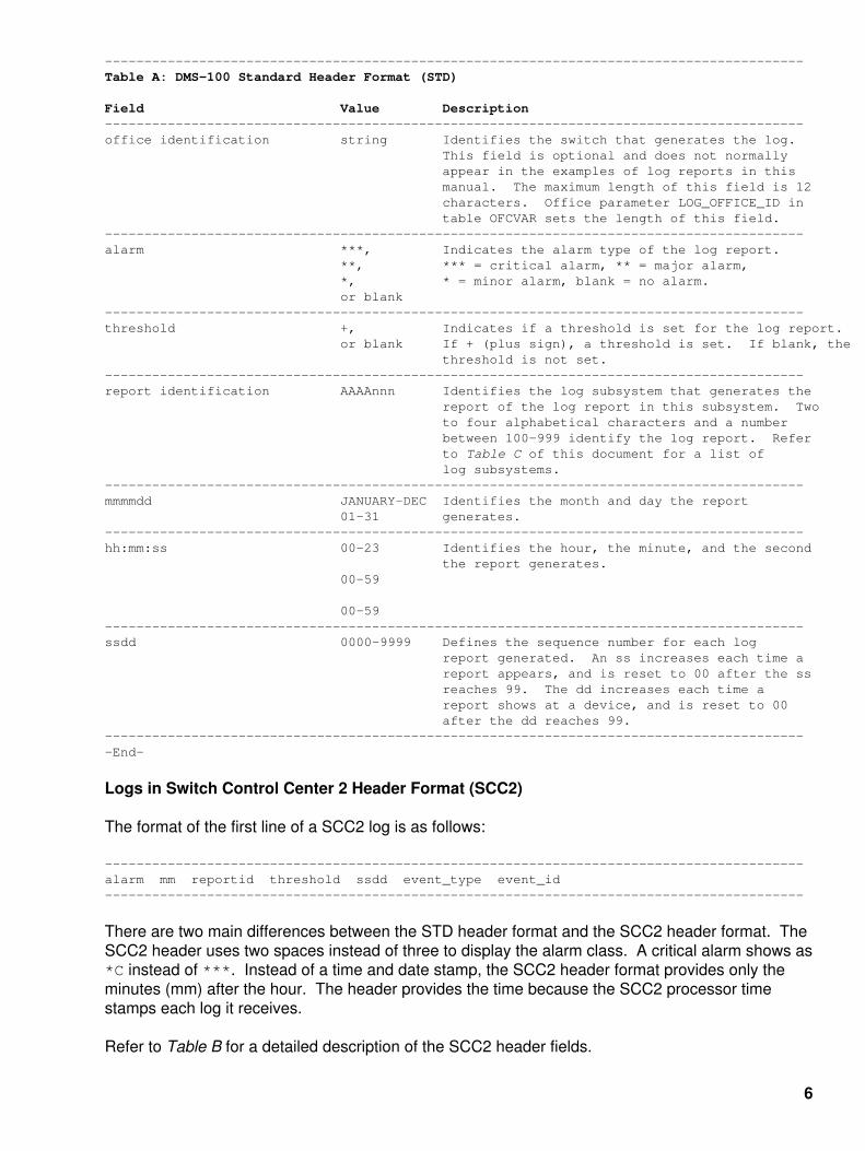
−−−−−−−−−−−−−−−−−−−−−−−−−−−−−−−−−−−−−−−−−−−−−−−−−−−−−−−−−−−−−−−−−−−−−−−−−−−−−−−−−−−−−−−−−Table A: DMS−100 Standard Header Format (STD)
Field Value Description−−−−−−−−−−−−−−−−−−−−−−−−−−−−−−−−−−−−−−−−−−−−−−−−−−−−−−−−−−−−−−−−−−−−−−−−−−−−−−−−−−−−−−−−−office identification string Identifies the switch that generates the log. This field is optional and does not normally appear in the examples of log reports in this manual. The maximum length of this field is 12 characters. Office parameter LOG_OFFICE_ID in table OFCVAR sets the length of this field.−−−−−−−−−−−−−−−−−−−−−−−−−−−−−−−−−−−−−−−−−−−−−−−−−−−−−−−−−−−−−−−−−−−−−−−−−−−−−−−−−−−−−−−−−alarm ***, Indicates the alarm type of the log report. **, *** = critical alarm, ** = major alarm, *, * = minor alarm, blank = no alarm. or blank−−−−−−−−−−−−−−−−−−−−−−−−−−−−−−−−−−−−−−−−−−−−−−−−−−−−−−−−−−−−−−−−−−−−−−−−−−−−−−−−−−−−−−−−−threshold +, Indicates if a threshold is set for the log report. or blank If + (plus sign), a threshold is set. If blank, the threshold is not set.−−−−−−−−−−−−−−−−−−−−−−−−−−−−−−−−−−−−−−−−−−−−−−−−−−−−−−−−−−−−−−−−−−−−−−−−−−−−−−−−−−−−−−−−−report identification AAAAnnn Identifies the log subsystem that generates the report of the log report in this subsystem. Two to four alphabetical characters and a number between 100−999 identify the log report. Refer to Table C of this document for a list of log subsystems.−−−−−−−−−−−−−−−−−−−−−−−−−−−−−−−−−−−−−−−−−−−−−−−−−−−−−−−−−−−−−−−−−−−−−−−−−−−−−−−−−−−−−−−−−mmmmdd JANUARY−DEC Identifies the month and day the report 01−31 generates.−−−−−−−−−−−−−−−−−−−−−−−−−−−−−−−−−−−−−−−−−−−−−−−−−−−−−−−−−−−−−−−−−−−−−−−−−−−−−−−−−−−−−−−−−hh:mm:ss 00−23 Identifies the hour, the minute, and the second the report generates. 00−59
00−59−−−−−−−−−−−−−−−−−−−−−−−−−−−−−−−−−−−−−−−−−−−−−−−−−−−−−−−−−−−−−−−−−−−−−−−−−−−−−−−−−−−−−−−−−ssdd 0000−9999 Defines the sequence number for each log report generated. An ss increases each time a report appears, and is reset to 00 after the ss reaches 99. The dd increases each time a report shows at a device, and is reset to 00 after the dd reaches 99.−−−−−−−−−−−−−−−−−−−−−−−−−−−−−−−−−−−−−−−−−−−−−−−−−−−−−−−−−−−−−−−−−−−−−−−−−−−−−−−−−−−−−−−−−−End−
Logs in Switch Control Center 2 Header Format (SCC2)
The format of the first line of a SCC2 log is as follows:
−−−−−−−−−−−−−−−−−−−−−−−−−−−−−−−−−−−−−−−−−−−−−−−−−−−−−−−−−−−−−−−−−−−−−−−−−−−−−−−−−−−−−−−−−alarm mm reportid threshold ssdd event_type event_id−−−−−−−−−−−−−−−−−−−−−−−−−−−−−−−−−−−−−−−−−−−−−−−−−−−−−−−−−−−−−−−−−−−−−−−−−−−−−−−−−−−−−−−−−
There are two main differences between the STD header format and the SCC2 header format. TheSCC2 header uses two spaces instead of three to display the alarm class. A critical alarm shows as*C instead of ***. Instead of a time and date stamp, the SCC2 header format provides only theminutes (mm) after the hour. The header provides the time because the SCC2 processor timestamps each log it receives.
Refer to Table B for a detailed description of the SCC2 header fields.
6

The format of the following lines of the log report is the same as the format for offices with Standardor ECORE headers.
An example of LINE101 log report that uses the SCC2 header follows:
−−−−−−−−−−−−−−−−−−−−−−−−−−−−−−−−−−−−−−−−−−−−−−−−−−−−−−−−−−−−−−−−−−−−−−−−−−−−−−−−−−−−−−−−−* 27 LINE 101 2112 FAIL LN_DIAG LEN HOST 03 0 14 24 DN 7811999 DIAGNOSTIC RESULT No Response from Peripheral ACTION REQUIRED Chk Periphls CARD TYPE 2X17AB−−−−−−−−−−−−−−−−−−−−−−−−−−−−−−−−−−−−−−−−−−−−−−−−−−−−−−−−−−−−−−−−−−−−−−−−−−−−−−−−−−−−−−−−−
Table B lists and explains the headers that log reports in SCC2 format include.
−−−−−−−−−−−−−−−−−−−−−−−−−−−−−−−−−−−−−−−−−−−−−−−−−−−−−−−−−−−−−−−−−−−−−−−−−−−−−−−−−−−−−−−−−Table B: DMS−100 SCC2 Header Format
Field Value Description−−−−−−−−−−−−−−−−−−−−−−−−−−−−−−−−−−−−−−−−−−−−−−−−−−−−−−−−−−−−−−−−−−−−−−−−−−−−−−−−−−−−−−−−− alarm *C, Indicates the report alarm type. *C is critical, **, ** is major, * is minor, blank is no alarm. *, or blank−−−−−−−−−−−−−−−−−−−−−−−−−−−−−−−−−−−−−−−−−−−−−−−−−−−−−−−−−−−−−−−−−−−−−−−−−−−−−−−−−−−−−−−−−mm 00−59 Identifies the number of minutes after the hour that the report generates.−−−−−−−−−−−−−−−−−−−−−−−−−−−−−−−−−−−−−−−−−−−−−−−−−−−−−−−−−−−−−−−−−−−−−−−−−−−−−−−−−−−−−−−−−report identification AAAA nnn Identifies the log subsystem that generates the report. This field uses two to four alphabetical characters and the number (100−999) of the log report in this subsystem. Note the subsystem name and the log number in this format. Refer to Table C for a list of log subsystems.−−−−−−−−−−−−−−−−−−−−−−−−−−−−−−−−−−−−−−−−−−−−−−−−−−−−−−−−−−−−−−−−−−−−−−−−−−−−−−−−−−−−−−−−−threshold +, Indicates if a threshold is set for the log report. or blank If + (plus sign), a threshold is set. If blank, the threshold is not set.−−−−−−−−−−−−−−−−−−−−−−−−−−−−−−−−−−−−−−−−−−−−−−−−−−−−−−−−−−−−−−−−−−−−−−−−−−−−−−−−−−−−−−−−−ssdd 0000−9999 Defines the sequence number for each log report generated. An ss increases each time a report appears, and is reset to 00 after the ss reaches 99. The dd increases each time a report shows at a device, and is reset to 00 after the dd reaches 99.−−−−−−−−−−−−−−−−−−−−−−−−−−−−−−−−−−−−−−−−−−−−−−−−−−−−−−−−−−−−−−−−−−−−−−−−−−−−−−−−−−−−−−−−−−End−
Event Type and Identification
The Event Type and Event Identification follows the header.
The event type is a one−word, general description of the occurrence that caused the switch togenerate the log report. Some examples of events are FLT, INFO, and SYSB. Refer to Table D fora list of event types and their meanings.
The event Identification is a string that provides additional information about the event. Normallythe string is abbreviated. The event identification can be omitted when the event type and the textin the variable message/data area supply enough information.
7

Variable Message / Data Area
Lines of variable text and data fields normally follow the event type and identification. These fieldsprovide additional information about one or more of the following:
DMS−100 Responses• Equipment Status• Hardware Identification• Problem Isolation• Problem Resolution• Software Identification•
Log reports have a variable message / data area. If the log report does not have a variablemessage data / area, the event type and identification provide information to determine the actionrequired.
Structure of a Log Report Description
This section details the log reports that the DMS−100 outputs. The following headings describeeach log report, in detail:
Report Format• Example• Explanation• Explanation Table• Action Taken• Associated OM Registers•
Log report descriptions can include the following:
Tables exact to the log report.• One or more Additional Information sections.• A table that explains a hexadecimal data dump.•
Report Format
The report format section is the first part of a log report description. The report format descriptionprovides a general model of the log report, and identifies constant and variable text. Refer to LogReport Formats in this document for additional information about the format fields.
Example
The example section is the second part of a log report description. It contains an example of the logreport as it comes from the DMS−100 switch.
Explanation
The explanation section is the third part of the log report description. It contains a short descriptionof the conditions that generate the report.
Explanation Table
The explanation table describes each field (logical part) of the log report in detail, under thecolumns: field, value, and description.
8

Field Column
The field column contains the following types of entry:
The event identification when present.• Constant fields, where the value does not change (normally written in uppercase).• Variable fields, where more than one possible value or a range of values (written in lowercase).• Mixed fields, that consist of a constant and an associated variable (written in a group of uppercase andlowercase letters).
•
Variables Represented
A small number of text variables, known to the reader, are represented by their abbreviations. Forexample: DN (Directory Number), LEN (Line Equipment Number), CLLI (Common LanguageLocation Identifier), TRKID (Trunk Identifier). For a complete list, refer to Table H.
Other text variables are represented by the suffix nm if they are names. For example, modnm formodule name. The suffix txt represents any other sort of character string. For example, stattxtfor state text, fltxt for fault text (a character string that represents a fault).
Decimal numbers are represented by n (where n is zero to nine, unless specified). Hexadecimalnumbers are represented by h (where h is zero to F, unless specified).
Value Column
Five types of values are in the value column:
Separate values.• Numeric ranges.• Symbolic text, indicating a range of values as described in the description column.• Constant, indicating only one value for the field.•
Description Column
The description may include the following information:
The meaning of the field.• The meaning of exact values.• Why the system displays a value.• The relationship between this and other fields.• References to tables that list and describe a set of values.• References to the Customer Data schema tables that define the range of values for an office.•
The general Action to be Taken section of this document gives the action for exact field values. Thesystem includes the action for exact field values in cases not covered in the document.
Action Taken
The Action to be Taken section explains what action should be taken by operating companypersonnel when the log report occurs.
Associated OM Registers
This section of the log report description lists Operational Measurements (OM) that associate withan exact log.
9

How to Understand Hex Tables in AUD and AUDT Log Reports
Most audit log reports (AUD and AUDT) output hex data blocks. This section contains theinformation to understand the hex values.
The documentation that explains hex data blocks has two parts. In the first part of thedocumentation, a diagram of the data fields contains the name of each field. The diagram of thedata fields contains the size of the field, and its location in the data blocks. In the second part of thedocumentation, each page of the diagram has text that explains the purpose of the fields.
The following example is from a standard hex data diagram. Notice that there are two 16−bit wordsin each row (in this occurrence, WORD 2 and 3). WORD 2 contains bits 32 through 47 of the hexdata blocks. WORD 3 has bits 48 through 63. The least significant bit in each word is on theright−hand side.
The field CPTLB extends across WORDS 2 and WORDS 3. Under CPTLB are two rows of fieldnames, one beginning with field MYINDEX and the other with field PRIMINDX. Next to thesenames are numbers in brackets that identify the size of the fields in bits.
The size of the field is in brackets around the first word of a field. A C for continuation replaces thesize in any additional words used by the field. For example, CPTLB begins in a word precedingWORD 2.
The diagram identifies some fields by number. The names of the fields are too large for the spaceallotted in the diagram. The numbers identify the numbered field names under the diagram.
In the preceding example, the diagram shows three rows of field names stacked on top of eachother. There are two possible relationships between these rows. One possibility is that each rowcan represent a separate overlay. This possibility means one or another displays, depending on theconditions software module, using a specified hexadecimal data structure. The other possibility isthat one row comprises subfields of the previous row.
The diagram alone does not specify which relationship exists. An overlay chart defines which fieldsare overlays. Where nested overlays are present, the overlay chart shows the link betweenthem. Fields that do not appear in the chart are subfields.
The overlay chart that accompanies WORD 3 in the previous example appears here. The fields oneither side of the word or can occupy WORD 3 but not at the same time.
10

OVERLAY STRUCTURE WORD 3 2,AUDIT,3,4 or LETTERC
The following figure provides a more detailed example.
The corresponding overlay chart for WORD 83 is:
In this example, the first set of overlay choices, includes subfield XLAB of the CHB field,TOPS_AREA, and FASTMOVE.
These overlays are present in both WORDS 82 and 83.
11

If you select XLAB, there are four new overlay choices in WORD 83, like LOG NETWORK,FILLER_BYTE. If you select AMADATA, AMAINCCB and fields 3 through 7 are the overlay choicesin bits 1328 through 1332. The ENTRY_CODE, field 8, fields 9 through F, and SPARE8B are theoverlay choices in bits 1336 through 1343.
Hexadecimal words in a diagram are numbered continuously from the beginning to the end of thehexadecimal data block. Word 0 corresponds to the top left word in the top row of the accurate logoutput.
The following example shows how actual hexadecimal output relates to the model of hexadecimaloutput in the diagram. For WORD 3 in the previous example, a dumped value of 9C5A is in thediagram as:
Unless stated, all numeric values that appear in the document audit log report descriptions aredecimal. Only the example of an accurate log report contains data in hexadecimal values.
Field descriptions for Boolean names are described as true or false. A name is true (1) if thecondition the field name defines exists. The name is false (0) if the condition the field name definesdoes not exist.
Information Only Logs
The switch generates these information only logs to alert maintenance personnel of the followingconditions:
A transient event occurred.• A switch state like Manual Busy occurred.• The system correctly tested a resource or service.• The system detected software data that was not expected.•
This log type normally does not require maintenance personnel to take any action. This log typedoes not affect service. It is possible that this document does not include detailed log reportdescriptions for these information only logs.
12

Nortel DMS−100 Log Report InformationTable C
Table C lists and explains the subsystems of the DMS−100 switch software that generate logreports.
−−−−−−−−−−−−−−−−−−−−−−−−−−−−−−−−−−−−−−−−−−−−−−−−−−−−−−−−−−−−−−−−−−−−−−−−−−−−−−−−−−−−−−−−− Name Critical Major Description−−−−−−−−−−−−−−−−−−−−−−−−−−−−−−−−−−−−−−−−−−−−−−−−−−−−−−−−−−−−−−−−−−−−−−−−−−−−−−−−−−−−−−−−−ACCS − − The Automatic Calling Card Services (ACCS) subsystem provides the capabilities to obtain information related to calling card services.−−−−−−−−−−−−−−−−−−−−−−−−−−−−−−−−−−−−−−−−−−−−−−−−−−−−−−−−−−−−−−−−−−−−−−−−−−−−−−−−−−−−−−−−−ACD − − The Automatic Call Distribution (ACD) subsystem provides equal distribution of calls to set answering positions. When all the positions are busy, the system queues the calls in the order of their arrival, according to call priority. The ACD performs audits to check for errors in each ACD group.−−−−−−−−−−−−−−−−−−−−−−−−−−−−−−−−−−−−−−−−−−−−−−−−−−−−−−−−−−−−−−−−−−−−−−−−−−−−−−−−−−−−−−−−−ACMS − − The Automatic Call Distribution (ACD) subsystem provides equal distribution of calls to set answering positions. when the positions are all busy, calls are prompted in the order of their arrival, taking into account call priority. The ACD performs audits to check for errors in each ACD group.−−−−−−−−−−−−−−−−−−−−−−−−−−−−−−−−−−−−−−−−−−−−−−−−−−−−−−−−−−−−−−−−−−−−−−−−−−−−−−−−−−−−−−−−−ACNS − − The Attendant Console Night Service (ACNS) subsystem controls the digits dialed to access night services provided by customers connected to MDC.−−−−−−−−−−−−−−−−−−−−−−−−−−−−−−−−−−−−−−−−−−−−−−−−−−−−−−−−−−−−−−−−−−−−−−−−−−−−−−−−−−−−−−−−−ACT − − The Activity (ACT) subsystem checks Central Control Complex (CCC) for transient mismatches between the active and inactive sides.−−−−−−−−−−−−−−−−−−−−−−−−−−−−−−−−−−−−−−−−−−−−−−−−−−−−−−−−−−−−−−−−−−−−−−−−−−−−−−−−−−−−−−−−− ALRM − − The Alarm (ALRM) subsystem checks the accuracy of connections to the Emergency Service Bureau (ESB). The Alarm subsystem sends indications of alarm conditions over a trunk to a remote operator position.−−−−−−−−−−−−−−−−−−−−−−−−−−−−−−−−−−−−−−−−−−−−−−−−−−−−−−−−−−−−−−−−−−−−−−−−−−−−−−−−−−−−−−−−−ALT − − The Automatic Line Testing (ALT) subsystem provides automatic testing for large groups of lines during low traffic periods.
The ALT performs on all line equipment. This includes peripherals, circuit cards, facilities, and connected telephones.−−−−−−−−−−−−−−−−−−−−−−−−−−−−−−−−−−−−−−−−−−−−−−−−−−−−−−−−−−−−−−−−−−−−−−−−−−−−−−−−−−−−−−−−−AMA − − The Automatic Message Accounting (AMA) subsystem gathers and records all necessary data for subscriber−dialed calls that can be billed.−−−−−−−−−−−−−−−−−−−−−−−−−−−−−−−−−−−−−−−−−−−−−−−−−−−−−−−−−−−−−−−−−−−−−−−−−−−−−−−−−−−−−−−−−AMAB − − The Automatic Message Accounting Buffer (AMAB) subsystem establishes and controls the AMA buffer. This buffer is where the AMA subsystem records data for subscriber−dialed calls that can be billed.−−−−−−−−−−−−−−−−−−−−−−−−−−−−−−−−−−−−−−−−−−−−−−−−−−−−−−−−−−−−−−−−−−−−−−−−−−−−−−−−−−−−−−−−−AOSS − − The Auxiliary Operator Services System (AOSS) subsystem allows operators to provide subscribers with services as directory help (local and long distance) and call intercept.−−−−−−−−−−−−−−−−−−−−−−−−−−−−−−−−−−−−−−−−−−−−−−−−−−−−−−−−−−−−−−−−−−−−−−−−−−−−−−−−−−−−−−−−−
13

−−−−−−−−−−−−−−−−−−−−−−−−−−−−−−−−−−−−−−−−−−−−−−−−−−−−−−−−−−−−−−−−−−−−−−−−−−−−−−−−−−−−−−−−−APS − − The Attendant Pay Station (APS) subsystem allows all lines in a service hall to route call information to an exact output device.−−−−−−−−−−−−−−−−−−−−−−−−−−−−−−−−−−−−−−−−−−−−−−−−−−−−−−−−−−−−−−−−−−−−−−−−−−−−−−−−−−−−−−−−−ARN − − The Automatic Recall with Name (ARN) subsystem uses the service node to provide an audible name announcement identifying the last caller to the two−level AR announcement.−−−−−−−−−−−−−−−−−−−−−−−−−−−−−−−−−−−−−−−−−−−−−−−−−−−−−−−−−−−−−−−−−−−−−−−−−−−−−−−−−−−−−−−−−ASR − − The Automatic Set Relocation (ASR) subsystem allows the user to move Integrated Voice and Data (IVD) sets from one location to another without technician interruption.−−−−−−−−−−−−−−−−−−−−−−−−−−−−−−−−−−−−−−−−−−−−−−−−−−−−−−−−−−−−−−−−−−−−−−−−−−−−−−−−−−−−−−−−−ATB − − The All Trunks Busy (ATB) subsystem checks for busy conditions on trunks that terminate to a single location.−−−−−−−−−−−−−−−−−−−−−−−−−−−−−−−−−−−−−−−−−−−−−−−−−−−−−−−−−−−−−−−−−−−−−−−−−−−−−−−−−−−−−−−−−ATME − 201, 204 The Automatic Transmission Measuring Equipment (ATME) subsystem controls equipment that makes transmission measurements ons circuits terminating at long distance switching centers. For example, international gateways.−−−−−−−−−−−−−−−−−−−−−−−−−−−−−−−−−−−−−−−−−−−−−−−−−−−−−−−−−−−−−−−−−−−−−−−−−−−−−−−−−−−−−−−−−ATT − − The Automatic Trunk Testing (ATT) subsystem provides automatic testing for outgoing trunks and outgoing parts of two−way trunks.−−−−−−−−−−−−−−−−−−−−−−−−−−−−−−−−−−−−−−−−−−−−−−−−−−−−−−−−−−−−−−−−−−−−−−−−−−−−−−−−−−−−−−−−−AUD − − The Audit (AUD) subsystem checks the accuracy of Central Control (CC) software and attempts to correct detected errors.−−−−−−−−−−−−−−−−−−−−−−−−−−−−−−−−−−−−−−−−−−−−−−−−−−−−−−−−−−−−−−−−−−−−−−−−−−−−−−−−−−−−−−−−−AUDT − − The Audit (AUDT) subsystem checks the accuracy of Peripheral Module (PM) software and attempts to correct detected errors.−−−−−−−−−−−−−−−−−−−−−−−−−−−−−−−−−−−−−−−−−−−−−−−−−−−−−−−−−−−−−−−−−−−−−−−−−−−−−−−−−−−−−−−−−BERT − − The Bit Error Rate Test (BERT) subsystem reports conditions concerning applications using Integrated Bit Error Rate Testers (IBERT).−−−−−−−−−−−−−−−−−−−−−−−−−−−−−−−−−−−−−−−−−−−−−−−−−−−−−−−−−−−−−−−−−−−−−−−−−−−−−−−−−−−−−−−−−BMS − − The Buffer Management System (BMS) subsystem reports conditions concerning the allocation and deallocation of buffer space to applications using BMS.−−−−−−−−−−−−−−−−−−−−−−−−−−−−−−−−−−−−−−−−−−−−−−−−−−−−−−−−−−−−−−−−−−−−−−−−−−−−−−−−−−−−−−−−−CC 107, 102, 104 The Central Control (CC) subsystem controls the data 128 112, 113, processing functions of a DMS−100 along with its associated 114, 120 Data Store (DS) and Program Store (PS).−−−−−−−−−−−−−−−−−−−−−−−−−−−−−−−−−−−−−−−−−−−−−−−−−−−−−−−−−−−−−−−−−−−−−−−−−−−−−−−−−−−−−−−−−CCI − − The Computer Consoles, Inc. (CCI) subsystem reports on messaging errors between a DMS−100 switch and a CCI (DAS/C) system. This subsystem also provides information on the error and indicates the call should be operator−handled.−−−−−−−−−−−−−−−−−−−−−−−−−−−−−−−−−−−−−−−−−−−−−−−−−−−−−−−−−−−−−−−−−−−−−−−−−−−−−−−−−−−−−−−−−CCIS − 104, 108, The Common Channel Interoffice Signaling (CCIS) 120, 122, subsystem controls information exchange between 130, 131 processor−equipped switching systems over a network of switching links.−−−−−−−−−−−−−−−−−−−−−−−−−−−−−−−−−−−−−−−−−−−−−−−−−−−−−−−−−−−−−−−−−−−−−−−−−−−−−−−−−−−−−−−−−CCS 209, 175, 231 The Common Channel Signaling (CCS) subsystem logs 210, report on CCS7 link−set and routeset management 213, functions. These functions include the maintenance of 214, signaling link−sets and the restoration of signaling to a link 215, in the event of link failure or other interruption in service. 218, 219−−−−−−−−−−−−−−−−−−−−−−−−−−−−−−−−−−−−−−−−−−−−−−−−−−−−−−−−−−−−−−−−−−−−−−−−−−−−−−−−−−−−−−−−−CDC − − The Customer Data Change (CDC) subsystem allows end office subscribers to change data through service orders from their premises.−−−−−−−−−−−−−−−−−−−−−−−−−−−−−−−−−−−−−−−−−−−−−−−−−−−−−−−−−−−−−−−−−−−−−−−−−−−−−−−−−−−−−−−−−
14

−−−−−−−−−−−−−−−−−−−−−−−−−−−−−−−−−−−−−−−−−−−−−−−−−−−−−−−−−−−−−−−−−−−−−−−−−−−−−−−−−−−−−−−−−CDIV − − The Call Diversion (CDIV) subsystem provides information concerning the Call Diversion feature.−−−−−−−−−−−−−−−−−−−−−−−−−−−−−−−−−−−−−−−−−−−−−−−−−−−−−−−−−−−−−−−−−−−−−−−−−−−−−−−−−−−−−−−−−CDRC − − The Call Detail Recording Call Entry (CDRC) subsystem controls data collection, recording, and storage for each call processed by the DMS−300 Gateway.−−−−−−−−−−−−−−−−−−−−−−−−−−−−−−−−−−−−−−−−−−−−−−−−−−−−−−−−−−−−−−−−−−−−−−−−−−−−−−−−−−−−−−−−−CDRE 100 101 The Call Detail Recording Extension Blocks (CDRE) subsystem accesses the recording unit required to record CDR data on a call processed by the DMS−300 Gateway.−−−−−−−−−−−−−−−−−−−−−−−−−−−−−−−−−−−−−−−−−−−−−−−−−−−−−−−−−−−−−−−−−−−−−−−−−−−−−−−−−−−−−−−−−CDRS − − The Call Detail Recording Call Processing (CDRS) subsystem determines if CDR is activated or not activated for calls processed by the DMS−300 Gateway.−−−−−−−−−−−−−−−−−−−−−−−−−−−−−−−−−−−−−−−−−−−−−−−−−−−−−−−−−−−−−−−−−−−−−−−−−−−−−−−−−−−−−−−−−CFW − − The Call Forwarding (CFW) subsystem controls a service−related feature that permits a station to redirect incoming calls to another station.−−−−−−−−−−−−−−−−−−−−−−−−−−−−−−−−−−−−−−−−−−−−−−−−−−−−−−−−−−−−−−−−−−−−−−−−−−−−−−−−−−−−−−−−−CM 105, 104, 112, The Computing Module (CM) subsystem controls the maintenance 109, 122, 125, and call processing capabilities of a DMS−100E Enhanced Core 111, 133, 137, switch. 116 158 −−−−−−−−−−−−−−−−−−−−−−−−−−−−−−−−−−−−−−−−−−−−−−−−−−−−−−−−−−−−−−−−−−−−−−−−−−−−−−−−−−−−−−−−−CMC − 101, 102, The Central Message Controller (CMC) subsystem controls a hardware 110, 111 entity in the Central Control Complex (CCC). The CMC provides an interface between the Central Control (CC) and the Network Message Controllers (NMC), or the Input/Output Controllers (IOC).−−−−−−−−−−−−−−−−−−−−−−−−−−−−−−−−−−−−−−−−−−−−−−−−−−−−−−−−−−−−−−−−−−−−−−−−−−−−−−−−−−−−−−−−−CP − − The Call Processing (CP) subsystem controls processes involved in the set up of connections through the DMS−100 network between the calling and called parties.−−−−−−−−−−−−−−−−−−−−−−−−−−−−−−−−−−−−−−−−−−−−−−−−−−−−−−−−−−−−−−−−−−−−−−−−−−−−−−−−−−−−−−−−−CPM − − The Core Package Modules (CPM) subsystem connect to the DMS−100. The CPM provide information on the link and node maintenance for the Data Package Network (DPN).−−−−−−−−−−−−−−−−−−−−−−−−−−−−−−−−−−−−−−−−−−−−−−−−−−−−−−−−−−−−−−−−−−−−−−−−−−−−−−−−−−−−−−−−−CRMG − − The Call Reference Manager (CRMG) subsystem controls the allocation and recording of call reference numbers on a switch.−−−−−−−−−−−−−−−−−−−−−−−−−−−−−−−−−−−−−−−−−−−−−−−−−−−−−−−−−−−−−−−−−−−−−−−−−−−−−−−−−−−−−−−−−CRT − − The Call Redirect (CRT) subsystem provides residential subscribers with the ability to transfer calls to a pre−defined routing directory number.−−−−−−−−−−−−−−−−−−−−−−−−−−−−−−−−−−−−−−−−−−−−−−−−−−−−−−−−−−−−−−−−−−−−−−−−−−−−−−−−−−−−−−−−−CSC − − The Customer Service Change (CSC) subsystem provides information concerning data changes to subscriber lines.−−−−−−−−−−−−−−−−−−−−−−−−−−−−−−−−−−−−−−−−−−−−−−−−−−−−−−−−−−−−−−−−−−−−−−−−−−−−−−−−−−−−−−−−−CTID − − The Clone Terminal Identifier (CTID) log reports notify operating company personnel about requests for the allocation of a clone virtual Terminal Identifier (TID).−−−−−−−−−−−−−−−−−−−−−−−−−−−−−−−−−−−−−−−−−−−−−−−−−−−−−−−−−−−−−−−−−−−−−−−−−−−−−−−−−−−−−−−−−C6TU − − The Channel 6 Test Utility (C6TU) subsystem provides unit testing of Common Channel Interoffice Signaling (CCIS) features.−−−−−−−−−−−−−−−−−−−−−−−−−−−−−−−−−−−−−−−−−−−−−−−−−−−−−−−−−−−−−−−−−−−−−−−−−−−−−−−−−−−−−−−−−C7TD − − The Common Channel Signaling (CCS7) Test Driver (C7TD) subsystem implements test procedures prescribed by the technician to analyze a CCS7 system network.−−−−−−−−−−−−−−−−−−−−−−−−−−−−−−−−−−−−−−−−−−−−−−−−−−−−−−−−−−−−−−−−−−−−−−−−−−−−−−−−−−−−−−−−−C7TU − − The Common Channel Signaling (CCS7) Test Utility (C7TU) subsystem records the messages or message attempts to and from the C7TU. Do not generate these logs in a office.−−−−−−−−−−−−−−−−−−−−−−−−−−−−−−−−−−−−−−−−−−−−−−−−−−−−−−−−−−−−−−−−−−−−−−−−−−−−−−−−−−−−−−−−−
15

−−−−−−−−−−−−−−−−−−−−−−−−−−−−−−−−−−−−−−−−−−−−−−−−−−−−−−−−−−−−−−−−−−−−−−−−−−−−−−−−−−−−−−−−−C7UP − − The Common Channel Signaling (CCS7) ISDN User Part (ISUP) (C7UP) subsystem controls circuit group blocking and circuit group not blocking messages. The subsystem controls the circuit groups as part of ISUP trunk maintenance.−−−−−−−−−−−−−−−−−−−−−−−−−−−−−−−−−−−−−−−−−−−−−−−−−−−−−−−−−−−−−−−−−−−−−−−−−−−−−−−−−−−−−−−−−DAS − − The Directory Assistance Service (DAS) subsystem enhances the Traffic Operator Position System (TOPS) by using DAS for servicing Directory Assistance (DA) and Intercept (INT) calls.−−−−−−−−−−−−−−−−−−−−−−−−−−−−−−−−−−−−−−−−−−−−−−−−−−−−−−−−−−−−−−−−−−−−−−−−−−−−−−−−−−−−−−−−−DCR − − The Dynamically Controlled Routing (DCR) subsystem determines other toll call destinations and enhances the quality of a toll network.−−−−−−−−−−−−−−−−−−−−−−−−−−−−−−−−−−−−−−−−−−−−−−−−−−−−−−−−−−−−−−−−−−−−−−−−−−−−−−−−−−−−−−−−−DDIS − − The Data Distributor (DDIS) subsystem monitors the DMS−100 database and collects line data changes for the Business Network Management (BNM) database.−−−−−−−−−−−−−−−−−−−−−−−−−−−−−−−−−−−−−−−−−−−−−−−−−−−−−−−−−−−−−−−−−−−−−−−−−−−−−−−−−−−−−−−−−DDM − − The Distributed Data Manager (DDM) subsystem updates the data of many DMS−100 nodes at the same time.−−−−−−−−−−−−−−−−−−−−−−−−−−−−−−−−−−−−−−−−−−−−−−−−−−−−−−−−−−−−−−−−−−−−−−−−−−−−−−−−−−−−−−−−−DISK − − The Disk subsystem manages files and volumes on disk drives of the System Load module (SLM).−−−−−−−−−−−−−−−−−−−−−−−−−−−−−−−−−−−−−−−−−−−−−−−−−−−−−−−−−−−−−−−−−−−−−−−−−−−−−−−−−−−−−−−−−DDU − 204 The Disk Drive Unit (DDU) subsystem controls the disk drive and associated power−converter card installed in an Input/Output (I/O) equipment frame.−−−−−−−−−−−−−−−−−−−−−−−−−−−−−−−−−−−−−−−−−−−−−−−−−−−−−−−−−−−−−−−−−−−−−−−−−−−−−−−−−−−−−−−−−DFIL − − The Datafill (DFIL) subsystem reports on call interruptions during call processing or debugging operations. The reports indicate entry errors. These errors can include specifying more than the maximum number of digits for one stage of outpulsing.−−−−−−−−−−−−−−−−−−−−−−−−−−−−−−−−−−−−−−−−−−−−−−−−−−−−−−−−−−−−−−−−−−−−−−−−−−−−−−−−−−−−−−−−−DIRP − − The Device Independent Recording Package (DIRP) subsystem directs data automatically from the different administrative and maintenance facilities to the correct recording devices.−−−−−−−−−−−−−−−−−−−−−−−−−−−−−−−−−−−−−−−−−−−−−−−−−−−−−−−−−−−−−−−−−−−−−−−−−−−−−−−−−−−−−−−−−DLC − − The Digital Link Control (DLC) subsystem provides a means of passing data to and from an IBM and a DMS−100 switch. Technicians and testers use this tool to load files or data, and is not generally available to the field.−−−−−−−−−−−−−−−−−−−−−−−−−−−−−−−−−−−−−−−−−−−−−−−−−−−−−−−−−−−−−−−−−−−−−−−−−−−−−−−−−−−−−−−−−DNC − − The Directory Number Check (DNC) subsystem is a test run by Faultsman digits test. It provides a mechanism for checking the Directory Number (DN) associated with the line. When you dial a DN, the switch checks the number. If the number is wrong, a DNC100 generates.−−−−−−−−−−−−−−−−−−−−−−−−−−−−−−−−−−−−−−−−−−−−−−−−−−−−−−−−−−−−−−−−−−−−−−−−−−−−−−−−−−−−−−−−−DNPC − − The Directory Number Primary inter−LATA Carrier (DNPC) subsystem allows an operating company to provide operator services. The operator services are for inter−LATA calls from equal access or not−equal access end offices.−−−−−−−−−−−−−−−−−−−−−−−−−−−−−−−−−−−−−−−−−−−−−−−−−−−−−−−−−−−−−−−−−−−−−−−−−−−−−−−−−−−−−−−−−DPNS − − The Digital Private Network Signaling (DPNS) subsystem is a Common Channel Signaling System used between Private Branch Exchanges (PBX). The DPNS logs reports on the state and events of DPNS links.−−−−−−−−−−−−−−−−−−−−−−−−−−−−−−−−−−−−−−−−−−−−−−−−−−−−−−−−−−−−−−−−−−−−−−−−−−−−−−−−−−−−−−−−−DPP 100 100, 101 The Distributed Processing Peripheral (DPP) subsystem provides the DMS−100 with Automatic Message Accounting (AMA) recording and data transmission capabilities. The AMA capabilities comply with the Bellcore specification for Automatic Message Accounting Transmission Systems (ATMAPS).−−−−−−−−−−−−−−−−−−−−−−−−−−−−−−−−−−−−−−−−−−−−−−−−−−−−−−−−−−−−−−−−−−−−−−−−−−−−−−−−−−−−−−−−−
16

−−−−−−−−−−−−−−−−−−−−−−−−−−−−−−−−−−−−−−−−−−−−−−−−−−−−−−−−−−−−−−−−−−−−−−−−−−−−−−−−−−−−−−−−−DRT − − The Digit Reception Test (DRT) is a test run by the Faultsman digit test. The test is to verify that the dialed digits are correctly received by the switch. Digits are dialed according to a preset order. Log DRT100 produces if the switch detects an error.−−−−−−−−−−−−−−−−−−−−−−−−−−−−−−−−−−−−−−−−−−−−−−−−−−−−−−−−−−−−−−−−−−−−−−−−−−−−−−−−−−−−−−−−−DTSR − − The Dial−Tone Speed Recording (DTSR) subsystem provides information on the activation/deactivation of the dialtone speed recorder.−−−−−−−−−−−−−−−−−−−−−−−−−−−−−−−−−−−−−−−−−−−−−−−−−−−−−−−−−−−−−−−−−−−−−−−−−−−−−−−−−−−−−−−−−DVI 100 101 The Data and Voice DS30 Interface (DVI) subsystem handles maintenance, state changes, and requests of the DVI node.−−−−−−−−−−−−−−−−−−−−−−−−−−−−−−−−−−−−−−−−−−−−−−−−−−−−−−−−−−−−−−−−−−−−−−−−−−−−−−−−−−−−−−−−−EAD − − The Engineering and Administration (EAD) subsystem provides an interface between the EAD Acquisition System (EADAS) and the DMS−100. Requested messages or transmission problem reports are sent to EAD.−−−−−−−−−−−−−−−−−−−−−−−−−−−−−−−−−−−−−−−−−−−−−−−−−−−−−−−−−−−−−−−−−−−−−−−−−−−−−−−−−−−−−−−−−EATS − − The Equal Access Traffic Separation (EATS) subsystem pegs traffic sent to default registers in the Traffic Separation Measurement System (TSMS).−−−−−−−−−−−−−−−−−−−−−−−−−−−−−−−−−−−−−−−−−−−−−−−−−−−−−−−−−−−−−−−−−−−−−−−−−−−−−−−−−−−−−−−−−ECO − − The Emergency Cutoff Interruption (ECO) subsystem provides the company with a mechanism for preventing calls that are not necessary during an emergency.−−−−−−−−−−−−−−−−−−−−−−−−−−−−−−−−−−−−−−−−−−−−−−−−−−−−−−−−−−−−−−−−−−−−−−−−−−−−−−−−−−−−−−−−−EKTS − − The Electronic−Key Telephone Service (EKTS) subsystem is a collection of voice band features from a base at central office. The features provide customers with key system capabilities. The EKTS allows call appearances of a single DN on a number of terminals.−−−−−−−−−−−−−−−−−−−−−−−−−−−−−−−−−−−−−−−−−−−−−−−−−−−−−−−−−−−−−−−−−−−−−−−−−−−−−−−−−−−−−−−−−EICTS − − The Enhanced Network Integrity Check Traffic Simulator (EICTS) subsystem tests the performance of the call paths or fabric of the network.−−−−−−−−−−−−−−−−−−−−−−−−−−−−−−−−−−−−−−−−−−−−−−−−−−−−−−−−−−−−−−−−−−−−−−−−−−−−−−−−−−−−−−−−−ENCP − − The Enhanced Network Call Processing (ENCP) subsystem controls processes in setting connections between calling and called parties in a DMS−100 Enhanced Network (ENET).−−−−−−−−−−−−−−−−−−−−−−−−−−−−−−−−−−−−−−−−−−−−−−−−−−−−−−−−−−−−−−−−−−−−−−−−−−−−−−−−−−−−−−−−−ENDB − − The Enhanced Network Data Base (ENDB) subsystem is a database audit system for the Enhanced Network (ENET).−−−−−−−−−−−−−−−−−−−−−−−−−−−−−−−−−−−−−−−−−−−−−−−−−−−−−−−−−−−−−−−−−−−−−−−−−−−−−−−−−−−−−−−−−ENET − − The Enhanced Network (ENET) subsystem provides information about computing module enhanced network maintenance.−−−−−−−−−−−−−−−−−−−−−−−−−−−−−−−−−−−−−−−−−−−−−−−−−−−−−−−−−−−−−−−−−−−−−−−−−−−−−−−−−−−−−−−−−ESA − − The Emergency Stand−Alone (ESA) subsystem permits local calling within a Remote Line Module (RLM) or Remote Line Concentrating Module (RLCM). The ESA permits these calls in the event of loss of communication with the host office.−−−−−−−−−−−−−−−−−−−−−−−−−−−−−−−−−−−−−−−−−−−−−−−−−−−−−−−−−−−−−−−−−−−−−−−−−−−−−−−−−−−−−−−−−ESG − − The Emergency Service Group (ESG) subsystem provides information on terminating hunt group options intended for use by emergency services.−−−−−−−−−−−−−−−−−−−−−−−−−−−−−−−−−−−−−−−−−−−−−−−−−−−−−−−−−−−−−−−−−−−−−−−−−−−−−−−−−−−−−−−−−EXT 103, 102, 107 The External Alarms (EXT) subsystem controls and tests the office 108 alarm unit.−−−−−−−−−−−−−−−−−−−−−−−−−−−−−−−−−−−−−−−−−−−−−−−−−−−−−−−−−−−−−−−−−−−−−−−−−−−−−−−−−−−−−−−−−E911 − − The Enhanced 911 (E911) subsystem provides a central emergency service by routing calls to correct Public−Safety Answering Points (PSAP).−−−−−−−−−−−−−−−−−−−−−−−−−−−−−−−−−−−−−−−−−−−−−−−−−−−−−−−−−−−−−−−−−−−−−−−−−−−−−−−−−−−−−−−−−
17

−−−−−−−−−−−−−−−−−−−−−−−−−−−−−−−−−−−−−−−−−−−−−−−−−−−−−−−−−−−−−−−−−−−−−−−−−−−−−−−−−−−−−−−−−FCO − − The FiberCenter OM Acquisition (FCO) process collects a set of specified OMs from the DMS−100 OM system. The FCO process sends the specified OMs to a client process on the FiberCenter Operational Controller (OPC).−−−−−−−−−−−−−−−−−−−−−−−−−−−−−−−−−−−−−−−−−−−−−−−−−−−−−−−−−−−−−−−−−−−−−−−−−−−−−−−−−−−−−−−−−FM − − The Focused Maintenance (FM) subsystem provides alarm information when failure counts for line and trunk problems exceed established thresholds.−−−−−−−−−−−−−−−−−−−−−−−−−−−−−−−−−−−−−−−−−−−−−−−−−−−−−−−−−−−−−−−−−−−−−−−−−−−−−−−−−−−−−−−−−FMT 100 101 The Fiber Multiplex Terminal (FMT) subsystem reports status changes of a FMT.−−−−−−−−−−−−−−−−−−−−−−−−−−−−−−−−−−−−−−−−−−−−−−−−−−−−−−−−−−−−−−−−−−−−−−−−−−−−−−−−−−−−−−−−−FRB − − The Faultsman Ringback (FRB) subsystem is a maintenance feature used by a field engineer to test continuity of a line. The field engineer can also make other adjustments on the premises of the subscribers.−−−−−−−−−−−−−−−−−−−−−−−−−−−−−−−−−−−−−−−−−−−−−−−−−−−−−−−−−−−−−−−−−−−−−−−−−−−−−−−−−−−−−−−−−FPRT − − The DMS−Core Footprint (FPRT) subsystem provides the ability to record the status and events that make the system start again.−−−−−−−−−−−−−−−−−−−−−−−−−−−−−−−−−−−−−−−−−−−−−−−−−−−−−−−−−−−−−−−−−−−−−−−−−−−−−−−−−−−−−−−−−FTR − − The Feature (FTR) subsystem provides information about the appl− ication of a treatment tone, announcement, or audio to an agent.−−−−−−−−−−−−−−−−−−−−−−−−−−−−−−−−−−−−−−−−−−−−−−−−−−−−−−−−−−−−−−−−−−−−−−−−−−−−−−−−−−−−−−−−−FTU − − The File Transfer System (FTU) subsystem provides information on the downloading of files to a remote DMS−100.−−−−−−−−−−−−−−−−−−−−−−−−−−−−−−−−−−−−−−−−−−−−−−−−−−−−−−−−−−−−−−−−−−−−−−−−−−−−−−−−−−−−−−−−−GWSA − − The Gateway Service Analysis (GWSA) subsystem controls class name of users authorized to access the input/output system of the DMS−300 Gateway. The authorized user obtains information concerning quality of call completion activities.−−−−−−−−−−−−−−−−−−−−−−−−−−−−−−−−−−−−−−−−−−−−−−−−−−−−−−−−−−−−−−−−−−−−−−−−−−−−−−−−−−−−−−−−−HEAP − − The HEAP subsystem is a memory control utility for use by call processing and other Support Operating System (SOS) processes. The HEAP logs inform users of the allocation and deallocation of memory at run time.−−−−−−−−−−−−−−−−−−−−−−−−−−−−−−−−−−−−−−−−−−−−−−−−−−−−−−−−−−−−−−−−−−−−−−−−−−−−−−−−−−−−−−−−−IBM − − International Business Machines (IBM) subsystem controls communication between a DMS−100 and the IBM Directory Assistance System (DAS). This communication provides support for the DMS−100 Auxiliary Operator Services System (AOSS). Refer to the explanation of the AOSS log subsystem in this table.−−−−−−−−−−−−−−−−−−−−−−−−−−−−−−−−−−−−−−−−−−−−−−−−−−−−−−−−−−−−−−−−−−−−−−−−−−−−−−−−−−−−−−−−−IBN − − The Integrated Business Network (IBN) subsystem controls a business services package that uses DMS−100 data−handling capabilities to provide a central telephone exchange service.−−−−−−−−−−−−−−−−−−−−−−−−−−−−−−−−−−−−−−−−−−−−−−−−−−−−−−−−−−−−−−−−−−−−−−−−−−−−−−−−−−−−−−−−−ICMO − 101, 102 The Incoming Message Overload (ICMO) subsystem measures incoming messages from the peripherals to the Central Control (CC). The ICMO subsystem measures the incoming messages over the two Central Message Controller (CMC) ports.−−−−−−−−−−−−−−−−−−−−−−−−−−−−−−−−−−−−−−−−−−−−−−−−−−−−−−−−−−−−−−−−−−−−−−−−−−−−−−−−−−−−−−−−−ICTS − − The Integrity Check Traffic Simulator (ICTS) subsystem identifies and corrects network accuracy problems in the absence of traffic. The ICTS sets up a large number of network connections. The peripherals associated with a connection monitor the accuracy and parity values transmitted over the connection. Defective hardware has the integrity counts incremented against the path data, as the system retains the connection on the specified plane. Access these counts through the NET INTEG level of the MAP terminal.−−−−−−−−−−−−−−−−−−−−−−−−−−−−−−−−−−−−−−−−−−−−−−−−−−−−−−−−−−−−−−−−−−−−−−−−−−−−−−−−−−−−−−−−−IDCHGGAT − − The International Digital Communication Charge Database Procedure Gate (IDCHGGAT) subsystem implements charge rate databases.−−−−−−−−−−−−−−−−−−−−−−−−−−−−−−−−−−−−−−−−−−−−−−−−−−−−−−−−−−−−−−−−−−−−−−−−−−−−−−−−−−−−−−−−−
18

−−−−−−−−−−−−−−−−−−−−−−−−−−−−−−−−−−−−−−−−−−−−−−−−−−−−−−−−−−−−−−−−−−−−−−−−−−−−−−−−−−−−−−−−−IDPL − − Identifier Pools (IDPL) manage the use of Transaction Application Part (TCAP) identifiers.−−−−−−−−−−−−−−−−−−−−−−−−−−−−−−−−−−−−−−−−−−−−−−−−−−−−−−−−−−−−−−−−−−−−−−−−−−−−−−−−−−−−−−−−−INIT − − The Initialization (INIT) subsystem provides information concerning the completion or failure of data initialization after a system starts again.−−−−−−−−−−−−−−−−−−−−−−−−−−−−−−−−−−−−−−−−−−−−−−−−−−−−−−−−−−−−−−−−−−−−−−−−−−−−−−−−−−−−−−−−−INTP − − The Interrupt (INTP) subsystem controls the message counter for messages processed by the CMC. The INTP allows quality measurements of CMC performance and message traffic flow.−−−−−−−−−−−−−−−−−−−−−−−−−−−−−−−−−−−−−−−−−−−−−−−−−−−−−−−−−−−−−−−−−−−−−−−−−−−−−−−−−−−−−−−−−IPGW − − The Internet Protocol Gateway subsystem provides maintenance access for the Gateway node.−−−−−−−−−−−−−−−−−−−−−−−−−−−−−−−−−−−−−−−−−−−−−−−−−−−−−−−−−−−−−−−−−−−−−−−−−−−−−−−−−−−−−−−−−IOAU − − The Input/Output Audit (IOAU) subsystem checks the accuracy of routes and devices. The system uses these routes and devices to achieve a bi−directional data exchange between I/O devices and the Central Control (CC).−−−−−−−−−−−−−−−−−−−−−−−−−−−−−−−−−−−−−−−−−−−−−−−−−−−−−−−−−−−−−−−−−−−−−−−−−−−−−−−−−−−−−−−−−IOD − 103, 104 The Input/Output Device (IOD) subsystem controls the hardware associated with devices used to achieve a bi−directional data exchange.−−−−−−−−−−−−−−−−−−−−−−−−−−−−−−−−−−−−−−−−−−−−−−−−−−−−−−−−−−−−−−−−−−−−−−−−−−−−−−−−−−−−−−−−−IOGA − − The Input/Output Gate (IOGA) subsystem retrieves the node number or name for the I/O device.−−−−−−−−−−−−−−−−−−−−−−−−−−−−−−−−−−−−−−−−−−−−−−−−−−−−−−−−−−−−−−−−−−−−−−−−−−−−−−−−−−−−−−−−−ISA − − The International Service Analysis (ISA) subsystem controls class identification of users authorized to access the input/output system. Authorized users obtain information concerning quality of call completion activities on international switches.−−−−−−−−−−−−−−−−−−−−−−−−−−−−−−−−−−−−−−−−−−−−−−−−−−−−−−−−−−−−−−−−−−−−−−−−−−−−−−−−−−−−−−−−−ISDN 112 111, 113 The Integrated Services Digital Network (ISDN) subsystem controls 114 communications of ISDN DMS−100 switches.−−−−−−−−−−−−−−−−−−−−−−−−−−−−−−−−−−−−−−−−−−−−−−−−−−−−−−−−−−−−−−−−−−−−−−−−−−−−−−−−−−−−−−−−−ISF − − The International Subscriber Feature (ISF) subsystem monitors the feature data updated by a subscriber.−−−−−−−−−−−−−−−−−−−−−−−−−−−−−−−−−−−−−−−−−−−−−−−−−−−−−−−−−−−−−−−−−−−−−−−−−−−−−−−−−−−−−−−−−ISP − − The ISDN Service Provisioning (ISP) subsystem provides information on the errors that occur while ISDN services perform.−−−−−−−−−−−−−−−−−−−−−−−−−−−−−−−−−−−−−−−−−−−−−−−−−−−−−−−−−−−−−−−−−−−−−−−−−−−−−−−−−−−−−−−−−ISUP − − The ISDN User Part (ISUP) subsystem provides information on the performance of ISUP trunks. The ISUP monitors performance in relation to known message volume, attempts not completed, and circuit availability.−−−−−−−−−−−−−−−−−−−−−−−−−−−−−−−−−−−−−−−−−−−−−−−−−−−−−−−−−−−−−−−−−−−−−−−−−−−−−−−−−−−−−−−−−ITN − − The Inter Network (ITN) subsystem operates the Transmission Control Protocol (TCP) for communication between SuperNode and third−party host computers by the Ethernet Interface Units (EIU).−−−−−−−−−−−−−−−−−−−−−−−−−−−−−−−−−−−−−−−−−−−−−−−−−−−−−−−−−−−−−−−−−−−−−−−−−−−−−−−−−−−−−−−−−ITOP − 106 The International Traffic Operator Position (ITOP) subsystem controls the international toll operator position consisting of a video display, keyboard, and headset. The ITOP monitors call details and enters routes and bills information.−−−−−−−−−−−−−−−−−−−−−−−−−−−−−−−−−−−−−−−−−−−−−−−−−−−−−−−−−−−−−−−−−−−−−−−−−−−−−−−−−−−−−−−−−KTRK − − The Killer Trunk Reporting (KTRK) subsystem reports trunks that exhibit at least one killer trunk property. These properties include killer trunk, slow release, always busy, or always idle.−−−−−−−−−−−−−−−−−−−−−−−−−−−−−−−−−−−−−−−−−−−−−−−−−−−−−−−−−−−−−−−−−−−−−−−−−−−−−−−−−−−−−−−−−
19

−−−−−−−−−−−−−−−−−−−−−−−−−−−−−−−−−−−−−−−−−−−−−−−−−−−−−−−−−−−−−−−−−−−−−−−−−−−−−−−−−−−−−−−−−LINE − − The Line Maintenance (LINE) subsystem controls the hardware and software entities associated with line equipment. These entities include, peripherals, circuit cards, facilities, and connected telephones.−−−−−−−−−−−−−−−−−−−−−−−−−−−−−−−−−−−−−−−−−−−−−−−−−−−−−−−−−−−−−−−−−−−−−−−−−−−−−−−−−−−−−−−−−LLC 100 − The Line Load Control (LLC) subsystem selectively denies call origination capabilities to specified subscriber lines. The LLC denies the origination when excessive demands for service are offered to the switching center.−−−−−−−−−−−−−−−−−−−−−−−−−−−−−−−−−−−−−−−−−−−−−−−−−−−−−−−−−−−−−−−−−−−−−−−−−−−−−−−−−−−−−−−−−LMAN − − The Load Management (LMAN) subsystem records each load command entered by the senior supervisor in an Automatic Call Distribution (ACD) setup.−−−−−−−−−−−−−−−−−−−−−−−−−−−−−−−−−−−−−−−−−−−−−−−−−−−−−−−−−−−−−−−−−−−−−−−−−−−−−−−−−−−−−−−−−LOST − − The Lost Message (LOST) documents incoming and outgoing messages, and messages that bounce back and are lost. The record includes the lost messages.−−−−−−−−−−−−−−−−−−−−−−−−−−−−−−−−−−−−−−−−−−−−−−−−−−−−−−−−−−−−−−−−−−−−−−−−−−−−−−−−−−−−−−−−−MCT − − The Malicious Call Trace (MCT) subsystem uses NTLS09 signaling between the DMS−100 switch and the local switching offices. The MCT gathers data for reports on malicious calls.−−−−−−−−−−−−−−−−−−−−−−−−−−−−−−−−−−−−−−−−−−−−−−−−−−−−−−−−−−−−−−−−−−−−−−−−−−−−−−−−−−−−−−−−−MDN − − The Multiple−Appearance Directory Number (MDN) subsystem provides information on software testing. Do not generate these log reports in an office.−−−−−−−−−−−−−−−−−−−−−−−−−−−−−−−−−−−−−−−−−−−−−−−−−−−−−−−−−−−−−−−−−−−−−−−−−−−−−−−−−−−−−−−−−MIS − − The Management Information System (MIS) subsystem provides a downstream processor with the ability to request Automatic Call Distribution (ACD) information from the DMS−100. This information is for old reports and real−time statistics.−−−−−−−−−−−−−−−−−−−−−−−−−−−−−−−−−−−−−−−−−−−−−−−−−−−−−−−−−−−−−−−−−−−−−−−−−−−−−−−−−−−−−−−−−MISC − − The Miscellaneous (MISC) subsystem provides information that allows debugging of trouble encountered in another subsystem.−−−−−−−−−−−−−−−−−−−−−−−−−−−−−−−−−−−−−−−−−−−−−−−−−−−−−−−−−−−−−−−−−−−−−−−−−−−−−−−−−−−−−−−−−MISM − − When a Mismatch (MISM) interrupt occurs, the mismatch logs are sent to the ACTSYS buffer. A mismatch log is not sent to any device printing logs at the time it occurs. The CC102 and CC105 logs print under normal conditions.−−−−−−−−−−−−−−−−−−−−−−−−−−−−−−−−−−−−−−−−−−−−−−−−−−−−−−−−−−−−−−−−−−−−−−−−−−−−−−−−−−−−−−−−−MM − 113 The Mismatch (MM) subsystem reports on mismatch and transient mismatch faults in a DMS−100E Enhanced Core switch.−−−−−−−−−−−−−−−−−−−−−−−−−−−−−−−−−−−−−−−−−−−−−−−−−−−−−−−−−−−−−−−−−−−−−−−−−−−−−−−−−−−−−−−−−MOD − − The Module (MOD) subsystem checks for software processing errors during call processing.−−−−−−−−−−−−−−−−−−−−−−−−−−−−−−−−−−−−−−−−−−−−−−−−−−−−−−−−−−−−−−−−−−−−−−−−−−−−−−−−−−−−−−−−−MPC − − The Multi−Protocol Controller (MPC) subsystem allows data communication between the DMS−100 and another computer. For example, a central office billing computer or another switch, through the use of any data communication protocol.−−−−−−−−−−−−−−−−−−−−−−−−−−−−−−−−−−−−−−−−−−−−−−−−−−−−−−−−−−−−−−−−−−−−−−−−−−−−−−−−−−−−−−−−−MS − 101, 103, The Message Switch (MS) subsystem performs the routing of 263 messages within the DMS−100E Enhanced Core switch.−−−−−−−−−−−−−−−−−−−−−−−−−−−−−−−−−−−−−−−−−−−−−−−−−−−−−−−−−−−−−−−−−−−−−−−−−−−−−−−−−−−−−−−−−MSRT − − The Message Routing (MSRT) subsystem provides information on primary rate access networking failures and rejections.−−−−−−−−−−−−−−−−−−−−−−−−−−−−−−−−−−−−−−−−−−−−−−−−−−−−−−−−−−−−−−−−−−−−−−−−−−−−−−−−−−−−−−−−−MTCB − − The Maintenance Base (MTCB) subsystem provides general support for maintenance software to implement a compatible method for PM software associated with different peripheral types.−−−−−−−−−−−−−−−−−−−−−−−−−−−−−−−−−−−−−−−−−−−−−−−−−−−−−−−−−−−−−−−−−−−−−−−−−−−−−−−−−−−−−−−−−MTD − 103 The Magnetic Tape Device (MTD) subsystem controls the magnetic tape loading device.−−−−−−−−−−−−−−−−−−−−−−−−−−−−−−−−−−−−−−−−−−−−−−−−−−−−−−−−−−−−−−−−−−−−−−−−−−−−−−−−−−−−−−−−−
20

−−−−−−−−−−−−−−−−−−−−−−−−−−−−−−−−−−−−−−−−−−−−−−−−−−−−−−−−−−−−−−−−−−−−−−−−−−−−−−−−−−−−−−−−−MTR − 116, 118, The Metering (MTR) subsystem provides a method for billing 123 subscribers for use of telephone network facilities during a call.−−−−−−−−−−−−−−−−−−−−−−−−−−−−−−−−−−−−−−−−−−−−−−−−−−−−−−−−−−−−−−−−−−−−−−−−−−−−−−−−−−−−−−−−−MTS − − The Message Transfer System (MTS) subsystem provides notification of messaging failures.−−−−−−−−−−−−−−−−−−−−−−−−−−−−−−−−−−−−−−−−−−−−−−−−−−−−−−−−−−−−−−−−−−−−−−−−−−−−−−−−−−−−−−−−−MTXT − − The Mobile Telephone Exchange Text (MTXT) log reports provide information about cellular phone services that the operating company provides to subscribers.−−−−−−−−−−−−−−−−−−−−−−−−−−−−−−−−−−−−−−−−−−−−−−−−−−−−−−−−−−−−−−−−−−−−−−−−−−−−−−−−−−−−−−−−−NCS − − The Network Control System (NCS) system connects with the DMS−100. The connection provides capabilities for operation and maintenance of services for the Packet Handler (PH) by the DMS−100.−−−−−−−−−−−−−−−−−−−−−−−−−−−−−−−−−−−−−−−−−−−−−−−−−−−−−−−−−−−−−−−−−−−−−−−−−−−−−−−−−−−−−−−−−NCAS − − The Non−Call Associated Signaling (NCAS) subsystem provides for signaling connections on Nortel Networks National ISDN Primary Rate Interface (NTNI PRI) links between Class 2 customer premise equipment and a DMS−100 switch.−−−−−−−−−−−−−−−−−−−−−−−−−−−−−−−−−−−−−−−−−−−−−−−−−−−−−−−−−−−−−−−−−−−−−−−−−−−−−−−−−−−−−−−−−NET − − The Network (NET) subsystem controls a group of circuits and terminals where transmission facilities interconnect subscriber stations directly or not directly. For example, as in line−to−line connections or as in line−to−trunk, or trunk−to−line connections.−−−−−−−−−−−−−−−−−−−−−−−−−−−−−−−−−−−−−−−−−−−−−−−−−−−−−−−−−−−−−−−−−−−−−−−−−−−−−−−−−−−−−−−−−NETM − 104, 116 The Network Maintenance (NETM) subsystem controls the status of 128 the network and its links. This subsystem also provides information on the results of diagnostic tests.−−−−−−−−−−−−−−−−−−−−−−−−−−−−−−−−−−−−−−−−−−−−−−−−−−−−−−−−−−−−−−−−−−−−−−−−−−−−−−−−−−−−−−−−−NOP 103 − The Network Operations Protocol (NOP) subsystem provides information concerning problems in file transfer. The NOP provides information concerning problems in transaction and pass through DMS MAP areas of the DMS−NOS (Network Operations System).−−−−−−−−−−−−−−−−−−−−−−−−−−−−−−−−−−−−−−−−−−−−−−−−−−−−−−−−−−−−−−−−−−−−−−−−−−−−−−−−−−−−−−−−−NO6 − 104 The Number 6 Signaling (NO6) checks Common Channel Signaling System (CCSS) integrity within the DMS−100. The CCSS uses an independent signaling network for transmission of telephony messages related to groups of speech circuits.−−−−−−−−−−−−−−−−−−−−−−−−−−−−−−−−−−−−−−−−−−−−−−−−−−−−−−−−−−−−−−−−−−−−−−−−−−−−−−−−−−−−−−−−−NPAC − 212 The Nortel Networks X.25 Controller (NPAC) subsystem reports details concerning X.25 protocol.−−−−−−−−−−−−−−−−−−−−−−−−−−−−−−−−−−−−−−−−−−−−−−−−−−−−−−−−−−−−−−−−−−−−−−−−−−−−−−−−−−−−−−−−−NSC − − The Number Services Code (NSC) subsystem reports on invalid data received by a Service Switching Point (SSP) for Enhanced 800 Service.−−−−−−−−−−−−−−−−−−−−−−−−−−−−−−−−−−−−−−−−−−−−−−−−−−−−−−−−−−−−−−−−−−−−−−−−−−−−−−−−−−−−−−−−−NSS − − The Network Services Software (NSS) subsystem provides a wide range of capabilities and functions associated with network services.−−−−−−−−−−−−−−−−−−−−−−−−−−−−−−−−−−−−−−−−−−−−−−−−−−−−−−−−−−−−−−−−−−−−−−−−−−−−−−−−−−−−−−−−−NWM − − The Network Management (NWM) subsystem controls a set of facilities that operate the DMS−100 Family network. The NWM objective is to make the best use of available resources during an overload or a facility failure.−−−−−−−−−−−−−−−−−−−−−−−−−−−−−−−−−−−−−−−−−−−−−−−−−−−−−−−−−−−−−−−−−−−−−−−−−−−−−−−−−−−−−−−−−N6 113, 111, 112, The Number 6 Signaling (N6) subsystem checks the accuracy 131, 114, 115, of the CCSS as it interacts outside the DMS−100 with other 140 123, 124, switches. 130, 134−−−−−−−−−−−−−−−−−−−−−−−−−−−−−−−−−−−−−−−−−−−−−−−−−−−−−−−−−−−−−−−−−−−−−−−−−−−−−−−−−−−−−−−−−
21

−−−−−−−−−−−−−−−−−−−−−−−−−−−−−−−−−−−−−−−−−−−−−−−−−−−−−−−−−−−−−−−−−−−−−−−−−−−−−−−−−−−−−−−−−N6TU − − The Number 6 Signaling Test Unit (N6TU) subsystem checks accuracy of test equipment used to verify the CCSS is operating correctly.−−−−−−−−−−−−−−−−−−−−−−−−−−−−−−−−−−−−−−−−−−−−−−−−−−−−−−−−−−−−−−−−−−−−−−−−−−−−−−−−−−−−−−−−−OAIN − − The Operator Advanced Intelligent Network (OAIN) subsystem is part of call processing and maintenance for Operator Services System Advanced Intelligent Network (OSSAIN). OSSAIN provides an interface between a DMS−100 TOPS switch and external service nodes.−−−−−−−−−−−−−−−−−−−−−−−−−−−−−−−−−−−−−−−−−−−−−−−−−−−−−−−−−−−−−−−−−−−−−−−−−−−−−−−−−−−−−−−−−OCCP − − The Occupancy Peak (OCCP) subsystem determines when the Central Control (CC) is operating under a high load percentage.−−−−−−−−−−−−−−−−−−−−−−−−−−−−−−−−−−−−−−−−−−−−−−−−−−−−−−−−−−−−−−−−−−−−−−−−−−−−−−−−−−−−−−−−−OCS − − The Overload Control System (OCS) subsystem provides information concerning problems related to the load on the central controller, caused by peak call processing demands.−−−−−−−−−−−−−−−−−−−−−−−−−−−−−−−−−−−−−−−−−−−−−−−−−−−−−−−−−−−−−−−−−−−−−−−−−−−−−−−−−−−−−−−−−OHBT − − The Off−Hook Balance Test (OHBT) optimizes the balance network for loaded subscriber loops. The OHBT determines the pad values necessary for the subscriber line to meet trans−hybrid loss requirements.−−−−−−−−−−−−−−−−−−−−−−−−−−−−−−−−−−−−−−−−−−−−−−−−−−−−−−−−−−−−−−−−−−−−−−−−−−−−−−−−−−−−−−−−−OMAP − − Operational Measurement Application Part (OMAP) logs document the results of Message Routing Verification Tests (MRVT).−−−−−−−−−−−−−−−−−−−−−−−−−−−−−−−−−−−−−−−−−−−−−−−−−−−−−−−−−−−−−−−−−−−−−−−−−−−−−−−−−−−−−−−−−OMPR − − The Operational Measurement Problem Reports (OMPR) document occurrences of problems encountered when attempting to accumulate statistics for OMRS subsystem log reports.−−−−−−−−−−−−−−−−−−−−−−−−−−−−−−−−−−−−−−−−−−−−−−−−−−−−−−−−−−−−−−−−−−−−−−−−−−−−−−−−−−−−−−−−−OMRS − − The Operational Measurement Reporting System (OMRS) provides OM periodic reports according to a known schedule.−−−−−−−−−−−−−−−−−−−−−−−−−−−−−−−−−−−−−−−−−−−−−−−−−−−−−−−−−−−−−−−−−−−−−−−−−−−−−−−−−−−−−−−−−OM2 − − The Operational Measurement 2 (OM2) checks accuracy of gathered statistics.−−−−−−−−−−−−−−−−−−−−−−−−−−−−−−−−−−−−−−−−−−−−−−−−−−−−−−−−−−−−−−−−−−−−−−−−−−−−−−−−−−−−−−−−−OOC − − The Overseas Operator Center (OOC) subsystem provides gateway operator services and rate and route information.−−−−−−−−−−−−−−−−−−−−−−−−−−−−−−−−−−−−−−−−−−−−−−−−−−−−−−−−−−−−−−−−−−−−−−−−−−−−−−−−−−−−−−−−−OSTR − − The Operator Services Trouble Report (OSTR) subsystem provides information on conference circuits in use by an Automatic Call Distribution (ACD) operator services platform.−−−−−−−−−−−−−−−−−−−−−−−−−−−−−−−−−−−−−−−−−−−−−−−−−−−−−−−−−−−−−−−−−−−−−−−−−−−−−−−−−−−−−−−−−PCH − − The Patch (PCH) subsystem reports conditions concerning the use of the DMS−100 patcher facility.−−−−−−−−−−−−−−−−−−−−−−−−−−−−−−−−−−−−−−−−−−−−−−−−−−−−−−−−−−−−−−−−−−−−−−−−−−−−−−−−−−−−−−−−−PEND − − The Pending Order System (PEND) provides facilities for storing data modification orders (service orders). These facilities also retrieve the service orders at the time specified for execution.−−−−−−−−−−−−−−−−−−−−−−−−−−−−−−−−−−−−−−−−−−−−−−−−−−−−−−−−−−−−−−−−−−−−−−−−−−−−−−−−−−−−−−−−−PES − − The Power and Environment System (PES) provides the means of controlling and monitoring the Outside Plant Module (OPM) cabinet service orders. The ESP provides the means for retrieving the OPM at the time specified for execution.−−−−−−−−−−−−−−−−−−−−−−−−−−−−−−−−−−−−−−−−−−−−−−−−−−−−−−−−−−−−−−−−−−−−−−−−−−−−−−−−−−−−−−−−−PM 170, 235, 105 The Peripheral Module (PM) controls all hardware and software 102 systems that provide interfaces with external line, trunk, or service facilities.−−−−−−−−−−−−−−−−−−−−−−−−−−−−−−−−−−−−−−−−−−−−−−−−−−−−−−−−−−−−−−−−−−−−−−−−−−−−−−−−−−−−−−−−−
22

−−−−−−−−−−−−−−−−−−−−−−−−−−−−−−−−−−−−−−−−−−−−−−−−−−−−−−−−−−−−−−−−−−−−−−−−−−−−−−−−−−−−−−−−−PMC − − The Printed Meter Check (PMC) subsystem sends a log to a printer for answered outgoing calls made on lines with the PMC option.−−−−−−−−−−−−−−−−−−−−−−−−−−−−−−−−−−−−−−−−−−−−−−−−−−−−−−−−−−−−−−−−−−−−−−−−−−−−−−−−−−−−−−−−−PRFM − − The Performance (PRFM) logs indicate the load on a PM and its performance under this load.−−−−−−−−−−−−−−−−−−−−−−−−−−−−−−−−−−−−−−−−−−−−−−−−−−−−−−−−−−−−−−−−−−−−−−−−−−−−−−−−−−−−−−−−−PRSM − − Post−Release Software Manager (PRSM) logs indicate conditions related to the use of PRSM.−−−−−−−−−−−−−−−−−−−−−−−−−−−−−−−−−−−−−−−−−−−−−−−−−−−−−−−−−−−−−−−−−−−−−−−−−−−−−−−−−−−−−−−−−QMIS − − The Queue Management System (QMIS) provides information about the transmission of a QMS buffer. −−−−−−−−−−−−−−−−−−−−−−−−−−−−−−−−−−−−−−−−−−−−−−−−−−−−−−−−−−−−−−−−−−−−−−−−−−−−−−−−−−−−−−−−−REPL − − The system generates the Report log (REPL) when updates are attempted during call processing and no journal file is available.−−−−−−−−−−−−−−−−−−−−−−−−−−−−−−−−−−−−−−−−−−−−−−−−−−−−−−−−−−−−−−−−−−−−−−−−−−−−−−−−−−−−−−−−−RLT − − The Network Attendant Service (NAS) Release Link Trunk (RLT) subsystem allows for decreasing the number of required trunk facilities. This decrease occurs when the attendant services are consolidated at one or more nodes in the network.−−−−−−−−−−−−−−−−−−−−−−−−−−−−−−−−−−−−−−−−−−−−−−−−−−−−−−−−−−−−−−−−−−−−−−−−−−−−−−−−−−−−−−−−−RMAN − − The Remote Load Management (RMAN) subsystem provides a downstream processor with the ability to issue Automatic Call Distribution (ACD) load management commands at a distance.−−−−−−−−−−−−−−−−−−−−−−−−−−−−−−−−−−−−−−−−−−−−−−−−−−−−−−−−−−−−−−−−−−−−−−−−−−−−−−−−−−−−−−−−−RMSG − − Rapid Messaging (RMSG) logs indicate conditions related to the use of ISDN Basic Rate Interface (BRI) Rapid Messaging.−−−−−−−−−−−−−−−−−−−−−−−−−−−−−−−−−−−−−−−−−−−−−−−−−−−−−−−−−−−−−−−−−−−−−−−−−−−−−−−−−−−−−−−−−RO − − The Remote Operation (RO) subsystem provides a general remote operation interface between applications in DMS−100 and external systems.−−−−−−−−−−−−−−−−−−−−−−−−−−−−−−−−−−−−−−−−−−−−−−−−−−−−−−−−−−−−−−−−−−−−−−−−−−−−−−−−−−−−−−−−−RONI − − The Remote−Operator Number Identification (RONI) subsystem checks for problems encountered during remote Central Automatic Message Accounting (CAMA) call attempts.−−−−−−−−−−−−−−−−−−−−−−−−−−−−−−−−−−−−−−−−−−−−−−−−−−−−−−−−−−−−−−−−−−−−−−−−−−−−−−−−−−−−−−−−−SA − − The Service Analysis (SA) subsystem controls class identification of users authorized to access the input/output system. The authorized user obtains information concerning quality of call completion activities.−−−−−−−−−−−−−−−−−−−−−−−−−−−−−−−−−−−−−−−−−−−−−−−−−−−−−−−−−−−−−−−−−−−−−−−−−−−−−−−−−−−−−−−−−SALN − − The Station Administration Line (SALN) subsystem reports on Line Equipment Number (LEN) data discrepancies. The SALN reports on LEN data discrepancies between the DMS−100 database and the Business Network Management (BNM) database. The SALN reports the discrepancies on a Digital Network Controller (DNC).−−−−−−−−−−−−−−−−−−−−−−−−−−−−−−−−−−−−−−−−−−−−−−−−−−−−−−−−−−−−−−−−−−−−−−−−−−−−−−−−−−−−−−−−−SCAI − − The Switch Computer Application Interface (SCAI) subsystem is a signaling interface provided by the DMS−100 to a host computer. The SCAI supports many different applications that require switch−host communication.−−−−−−−−−−−−−−−−−−−−−−−−−−−−−−−−−−−−−−−−−−−−−−−−−−−−−−−−−−−−−−−−−−−−−−−−−−−−−−−−−−−−−−−−−SCP − − The Service Control Point (SCP) subsystem reports results or SCP local subsystem management audits.−−−−−−−−−−−−−−−−−−−−−−−−−−−−−−−−−−−−−−−−−−−−−−−−−−−−−−−−−−−−−−−−−−−−−−−−−−−−−−−−−−−−−−−−−SCR − − The Selective Charge Recording (SCR) subsystem allows the charges for the current call quoted to the subscriber at the completion of a call. Only subscribers which have this feature can use the SCR subsystem−−−−−−−−−−−−−−−−−−−−−−−−−−−−−−−−−−−−−−−−−−−−−−−−−−−−−−−−−−−−−−−−−−−−−−−−−−−−−−−−−−−−−−−−−
23

−−−−−−−−−−−−−−−−−−−−−−−−−−−−−−−−−−−−−−−−−−−−−−−−−−−−−−−−−−−−−−−−−−−−−−−−−−−−−−−−−−−−−−−−−SCSS − − Special Connection Special Services (SCSS) subsystem provides for nailed−up hairpin and side door connections between special−service lines and DS−1 channels. The SCSS provides the connections through a Subscriber Module Urban (SMU).−−−−−−−−−−−−−−−−−−−−−−−−−−−−−−−−−−−−−−−−−−−−−−−−−−−−−−−−−−−−−−−−−−−−−−−−−−−−−−−−−−−−−−−−−SDMB 355 355 SuperNode Data Manager Billing (SDMB) logs indicate conditions related to the use of the SDMB subsystem.−−−−−−−−−−−−−−−−−−−−−−−−−−−−−−−−−−−−−−−−−−−−−−−−−−−−−−−−−−−−−−−−−−−−−−−−−−−−−−−−−−−−−−−−−SDS − − Special Delivery Service (SDS) logs indicate conditions related to SDS processing.−−−−−−−−−−−−−−−−−−−−−−−−−−−−−−−−−−−−−−−−−−−−−−−−−−−−−−−−−−−−−−−−−−−−−−−−−−−−−−−−−−−−−−−−−SEAS − − The Signaling Engineering Administration System (SEAS) provides operating company Signaling Engineering and Administration Center (SEAC) personnel with mechanized support capabilities. With the mechanized support capabilities, SEAC personnel can provision, engineer, and administer networks of Signal Transfer Points (STP) and signaling links.−−−−−−−−−−−−−−−−−−−−−−−−−−−−−−−−−−−−−−−−−−−−−−−−−−−−−−−−−−−−−−−−−−−−−−−−−−−−−−−−−−−−−−−−−SECU − − The Security (SECU) subsystem controls login and logout procedures, input commands, passwords, and priority login procedures for classified users.−−−−−−−−−−−−−−−−−−−−−−−−−−−−−−−−−−−−−−−−−−−−−−−−−−−−−−−−−−−−−−−−−−−−−−−−−−−−−−−−−−−−−−−−−SLE − − The Screening List Editing (SLE) subsystem provides the interface to screen out incoming calls for special treatment.−−−−−−−−−−−−−−−−−−−−−−−−−−−−−−−−−−−−−−−−−−−−−−−−−−−−−−−−−−−−−−−−−−−−−−−−−−−−−−−−−−−−−−−−−SLM − 200, 202, The System Load Module (SLM) subsystem offers a reliable and 206, 208, good loading capability for DMS−100E Enhanced Core switches. 403−−−−−−−−−−−−−−−−−−−−−−−−−−−−−−−−−−−−−−−−−−−−−−−−−−−−−−−−−−−−−−−−−−−−−−−−−−−−−−−−−−−−−−−−−SLNK 107, − The SL−100 Link (SLNK) ACD feature distributes a large number 108 of incoming calls among a number of telephone (ACD) positions. The SLNK logs provide a hard−copy history of the activities that occur on each data link.−−−−−−−−−−−−−−−−−−−−−−−−−−−−−−−−−−−−−−−−−−−−−−−−−−−−−−−−−−−−−−−−−−−−−−−−−−−−−−−−−−−−−−−−−SLNW − − The SL−100 Network Control (SLNW) logs report on data communication applications between the Subregional Control Facility (SRCF) and the SL−100. The system generates the logs when the SL−100 fails to:
* Establish a network connection. * Receive a message from the network connection. * Receive an acknowledgment from the remote application. * Send the message to the network connection.−−−−−−−−−−−−−−−−−−−−−−−−−−−−−−−−−−−−−−−−−−−−−−−−−−−−−−−−−−−−−−−−−−−−−−−−−−−−−−−−−−−−−−−−−SMDI 108 103 The Simplified Message Desk Interface (SMDI) subsystem provides communication between the DMS−100 and a message desk. A message desk serves as an answering service for stations that have their calls forwarded.−−−−−−−−−−−−−−−−−−−−−−−−−−−−−−−−−−−−−−−−−−−−−−−−−−−−−−−−−−−−−−−−−−−−−−−−−−−−−−−−−−−−−−−−−SME − − The Signaling Management Environment (SME) subsystem contains software that implements operating ISDN Basic Rate Access (BRA) basic calling.−−−−−−−−−−−−−−−−−−−−−−−−−−−−−−−−−−−−−−−−−−−−−−−−−−−−−−−−−−−−−−−−−−−−−−−−−−−−−−−−−−−−−−−−−SNAC − 103 The Switching Network Analysis Center (SNAC) subsystem is a method by which operators at a TOPS position can report trouble. The operator enters a 2−digit trouble code that causes the SNAC subsystem to generate a log report detailing the trouble.−−−−−−−−−−−−−−−−−−−−−−−−−−−−−−−−−−−−−−−−−−−−−−−−−−−−−−−−−−−−−−−−−−−−−−−−−−−−−−−−−−−−−−−−−SOS 100, − The Support Operating System (SOS) reports that certain 101, operations have occurred. These operations include a dump, 110 or use (or attempted use) of priority or privileged commands.−−−−−−−−−−−−−−−−−−−−−−−−−−−−−−−−−−−−−−−−−−−−−−−−−−−−−−−−−−−−−−−−−−−−−−−−−−−−−−−−−−−−−−−−−
24

−−−−−−−−−−−−−−−−−−−−−−−−−−−−−−−−−−−−−−−−−−−−−−−−−−−−−−−−−−−−−−−−−−−−−−−−−−−−−−−−−−−−−−−−−SPC − − The Semi−Permanent Connection (SPC) subsystem reports on the state of semi−permanent connections. These connections include line−to−line, trunk−to−trunk, or line−to−trunk which may be set up or taken down by administrative personnel through table control.−−−−−−−−−−−−−−−−−−−−−−−−−−−−−−−−−−−−−−−−−−−−−−−−−−−−−−−−−−−−−−−−−−−−−−−−−−−−−−−−−−−−−−−−−SRC − − The System Recovery Controller (SRC) system.−−−−−−−−−−−−−−−−−−−−−−−−−−−−−−−−−−−−−−−−−−−−−−−−−−−−−−−−−−−−−−−−−−−−−−−−−−−−−−−−−−−−−−−−−SS − − The Special Services (SS) substation includes telecommunications services other than Plain Ordinary Telephone Service (POTS), coin, and simple business services.−−−−−−−−−−−−−−−−−−−−−−−−−−−−−−−−−−−−−−−−−−−−−−−−−−−−−−−−−−−−−−−−−−−−−−−−−−−−−−−−−−−−−−−−−STOR − − The Store Allocator (STOR) subsystem maintains a set of critical data structures that it modifies each time an application allocates or deallocates store.−−−−−−−−−−−−−−−−−−−−−−−−−−−−−−−−−−−−−−−−−−−−−−−−−−−−−−−−−−−−−−−−−−−−−−−−−−−−−−−−−−−−−−−−−SWCT − 103 The Switch in Activity (SWCT) subsystem provides information that concerns the completion or failure of each SWCT step attempted.−−−−−−−−−−−−−−−−−−−−−−−−−−−−−−−−−−−−−−−−−−−−−−−−−−−−−−−−−−−−−−−−−−−−−−−−−−−−−−−−−−−−−−−−−SWER − − The Software Error (SWER) subsystem provides information that concerns software errors found during code execution that include the code location where trouble was encountered. The SWER also provides the code location where the system generates a log report when the LOGTRACE utility is turned on.−−−−−−−−−−−−−−−−−−−−−−−−−−−−−−−−−−−−−−−−−−−−−−−−−−−−−−−−−−−−−−−−−−−−−−−−−−−−−−−−−−−−−−−−−SWNR − − The Switch of Activity/Node (SWNR) subsystem provides information on the state of different nodes in response to a warm SWCT, a transfer of control to the backup CC with no loss of service.−−−−−−−−−−−−−−−−−−−−−−−−−−−−−−−−−−−−−−−−−−−−−−−−−−−−−−−−−−−−−−−−−−−−−−−−−−−−−−−−−−−−−−−−−SYNC − − The Synchronous Clock (SYNC) subsystem controls the DMS−100 clocks so the clocks run in sync and follow industry time standards.−−−−−−−−−−−−−−−−−−−−−−−−−−−−−−−−−−−−−−−−−−−−−−−−−−−−−−−−−−−−−−−−−−−−−−−−−−−−−−−−−−−−−−−−−TABL − − The Table (TABL) subsystem indicates a user has accessed or attempted to access a Customer Data table in read or write mode.−−−−−−−−−−−−−−−−−−−−−−−−−−−−−−−−−−−−−−−−−−−−−−−−−−−−−−−−−−−−−−−−−−−−−−−−−−−−−−−−−−−−−−−−−TCAP − − The Transaction Capabilities Application Part (TCAP) subsystem provides a common protocol for remote operations across the CCS7 network.−−−−−−−−−−−−−−−−−−−−−−−−−−−−−−−−−−−−−−−−−−−−−−−−−−−−−−−−−−−−−−−−−−−−−−−−−−−−−−−−−−−−−−−−−TCCI − − The TOPS CCI (TCCI) subsystem provides support for messaging protocol between the DMS−100 TOPS voice response and the Computer Consoles Inc. Directory Assistance System (CCI DAS/C) database.−−−−−−−−−−−−−−−−−−−−−−−−−−−−−−−−−−−−−−−−−−−−−−−−−−−−−−−−−−−−−−−−−−−−−−−−−−−−−−−−−−−−−−−−−TEOL − − The TOPS subsystem generates TOPS End−of−Life (TEOL) messages that list all functionality areas used in the previous week that are scheduled for removal from the TOPS software load at a future date.−−−−−−−−−−−−−−−−−−−−−−−−−−−−−−−−−−−−−−−−−−−−−−−−−−−−−−−−−−−−−−−−−−−−−−−−−−−−−−−−−−−−−−−−−TFAN − − The Traffic Analysis (TFAN) subsystem controls the flow of traffic data to the default OM registers.−−−−−−−−−−−−−−−−−−−−−−−−−−−−−−−−−−−−−−−−−−−−−−−−−−−−−−−−−−−−−−−−−−−−−−−−−−−−−−−−−−−−−−−−−TH − − The Testhead (TH) subsystem provides support to test and maintain Test Access Controller (TAC) cards in the TAC peripheral.−−−−−−−−−−−−−−−−−−−−−−−−−−−−−−−−−−−−−−−−−−−−−−−−−−−−−−−−−−−−−−−−−−−−−−−−−−−−−−−−−−−−−−−−−TKCV − − The Trunk Conversion (TKCV) subsystem provides a method to convert Per−Trunk Signaling (PTS) trunks to ISDN User Part (ISUP) trunks to make use of the SS7 signaling protocol.−−−−−−−−−−−−−−−−−−−−−−−−−−−−−−−−−−−−−−−−−−−−−−−−−−−−−−−−−−−−−−−−−−−−−−−−−−−−−−−−−−−−−−−−−
25

−−−−−−−−−−−−−−−−−−−−−−−−−−−−−−−−−−−−−−−−−−−−−−−−−−−−−−−−−−−−−−−−−−−−−−−−−−−−−−−−−−−−−−−−−TME − − The Terminal Management Environment (TME) subsystem integrates applications. This provides greater functionality in available services.−−−−−−−−−−−−−−−−−−−−−−−−−−−−−−−−−−−−−−−−−−−−−−−−−−−−−−−−−−−−−−−−−−−−−−−−−−−−−−−−−−−−−−−−−TOPS 304 504 The TOPS controls the Toll Operator Position. The toll operator position consists of a video display and keyboard for monitoring call details and entering routing and billing information.−−−−−−−−−−−−−−−−−−−−−−−−−−−−−−−−−−−−−−−−−−−−−−−−−−−−−−−−−−−−−−−−−−−−−−−−−−−−−−−−−−−−−−−−−TPS − − The Transaction Processing System (TPS) indicates problems. These problems include errors found by the TPS input handler on receipt of TPS messages. These problems also include errors found while auditing SCB letters.−−−−−−−−−−−−−−−−−−−−−−−−−−−−−−−−−−−−−−−−−−−−−−−−−−−−−−−−−−−−−−−−−−−−−−−−−−−−−−−−−−−−−−−−−TRAP − − The Software Trap (TRAP) subsystem provides information concerning software errors found during code execution. This information includes the code location where the system encountered the problem. −−−−−−−−−−−−−−−−−−−−−−−−−−−−−−−−−−−−−−−−−−−−−−−−−−−−−−−−−−−−−−−−−−−−−−−−−−−−−−−−−−−−−−−−−TRK 103 − The Trunk Maintenance (TRK) subsystem controls the hardware and software associated with trunk equipment. This hardware and software includes peripherals, circuit cards, and facilities.−−−−−−−−−−−−−−−−−−−−−−−−−−−−−−−−−−−−−−−−−−−−−−−−−−−−−−−−−−−−−−−−−−−−−−−−−−−−−−−−−−−−−−−−−UTR − − The Universal Tone Receiver (UTR) subsystem provides information when the UTR fails to receive OM from an International Digital Trunk Controller (IDTC).−−−−−−−−−−−−−−−−−−−−−−−−−−−−−−−−−−−−−−−−−−−−−−−−−−−−−−−−−−−−−−−−−−−−−−−−−−−−−−−−−−−−−−−−−VIP − − The Very Important Person (VIP) subsystem provides a method of restructuring traffic to any number of specified Local Exchange Codes (LEC).−−−−−−−−−−−−−−−−−−−−−−−−−−−−−−−−−−−−−−−−−−−−−−−−−−−−−−−−−−−−−−−−−−−−−−−−−−−−−−−−−−−−−−−−−VMX − − The Voice Message Exchange (VMX) checks the Message Waiting Indicator (MWI) of a subscriber for activation, deactivation, and failure of activation/deactivation.−−−−−−−−−−−−−−−−−−−−−−−−−−−−−−−−−−−−−−−−−−−−−−−−−−−−−−−−−−−−−−−−−−−−−−−−−−−−−−−−−−−−−−−−−VSN − − The Voice Services Node (VSN) subsystem communicates with the DMS−100 through an application protocol to provide voice recognition and play announcements for the subscribers.−−−−−−−−−−−−−−−−−−−−−−−−−−−−−−−−−−−−−−−−−−−−−−−−−−−−−−−−−−−−−−−−−−−−−−−−−−−−−−−−−−−−−−−−−WHC − − The Who's Calling (WHC) subsystem intercepts incoming calls received with the directory number blocked (private) or not available (unavailable) for delivery. The subsystem requests, records, and delivers the caller's name to the residential subscriber. The subscriber receives multiple options to handle the intercepted call.−−−−−−−−−−−−−−−−−−−−−−−−−−−−−−−−−−−−−−−−−−−−−−−−−−−−−−−−−−−−−−−−−−−−−−−−−−−−−−−−−−−−−−−−−XIP − − The XPM Internet Protocol (XIP) is used for communications between the CM and an Ethernet enabled SX05 XPM.−−−−−−−−−−−−−−−−−−−−−−−−−−−−−−−−−−−−−−−−−−−−−−−−−−−−−−−−−−−−−−−−−−−−−−−−−−−−−−−−−−−−−−−−−XSM − − The Extended System Monitor (XSM) subsystem represents a microprocessor−based circuit pack (NT8D22AC) located in an Intelligent Peripheral Equipment (IPE) pedestal. The XSM monitors IPE power supplies, ring generators, column thermal state, blower unit operation, available Uninterruptable Power Supply (UPS), units, and available Battery Power Distribution Units (BPDU).−−−−−−−−−−−−−−−−−−−−−−−−−−−−−−−−−−−−−−−−−−−−−−−−−−−−−−−−−−−−−−−−−−−−−−−−−−−−−−−−−−−−−−−−−−End−
26

Nortel DMS−100 Log Report InformationTable D & E & F
Table D lists and explains the event types that log reports include.
−−−−−−−−−−−−−−−−−−−−−−−−−−−−−−−−−−−−−−−−−−−−−−−−−−−−−−−−−−−−−−−−−−−−−−−−−−−−−−−−−−−−−−−−−Table D: DMS−100 Event Types
Event Description−−−−−−−−−−−−−−−−−−−−−−−−−−−−−−−−−−−−−−−−−−−−−−−−−−−−−−−−−−−−−−−−−−−−−−−−−−−−−−−−−−−−−−−−−CBSY Central−Side Busy. The equipment is not available on the side nearest the CCC.−−−−−−−−−−−−−−−−−−−−−−−−−−−−−−−−−−−−−−−−−−−−−−−−−−−−−−−−−−−−−−−−−−−−−−−−−−−−−−−−−−−−−−−−−EXC Exception. The system encountered either software or hardware trouble during normal call processing operation.−−−−−−−−−−−−−−−−−−−−−−−−−−−−−−−−−−−−−−−−−−−−−−−−−−−−−−−−−−−−−−−−−−−−−−−−−−−−−−−−−−−−−−−−−FAIL The system detected a hardware−related defect during diagnostic testing of the equipment.−−−−−−−−−−−−−−−−−−−−−−−−−−−−−−−−−−−−−−−−−−−−−−−−−−−−−−−−−−−−−−−−−−−−−−−−−−−−−−−−−−−−−−−−−FLT Refer to Fault. The system encountered a software defect, probably on a block−read or block−write.−−−−−−−−−−−−−−−−−−−−−−−−−−−−−−−−−−−−−−−−−−−−−−−−−−−−−−−−−−−−−−−−−−−−−−−−−−−−−−−−−−−−−−−−−INFO Refer to Information. The system produced information, important to the operation of the DMS−100 switch, that does not reflect a service−affecting event.−−−−−−−−−−−−−−−−−−−−−−−−−−−−−−−−−−−−−−−−−−−−−−−−−−−−−−−−−−−−−−−−−−−−−−−−−−−−−−−−−−−−−−−−−INIT Refer to Initialization. The system had either a warm, cold, or Initial Program Load (IPL) restart.−−−−−−−−−−−−−−−−−−−−−−−−−−−−−−−−−−−−−−−−−−−−−−−−−−−−−−−−−−−−−−−−−−−−−−−−−−−−−−−−−−−−−−−−−LO Refer to Lockout. The equipment is either placed on or removed from the Lockout (LO) list.−−−−−−−−−−−−−−−−−−−−−−−−−−−−−−−−−−−−−−−−−−−−−−−−−−−−−−−−−−−−−−−−−−−−−−−−−−−−−−−−−−−−−−−−−MANB Manual Busy. A technician removed the equipment from service. The technician removes the equipment by operation of a panel control, or by a command entered at the MAP terminal.−−−−−−−−−−−−−−−−−−−−−−−−−−−−−−−−−−−−−−−−−−−−−−−−−−−−−−−−−−−−−−−−−−−−−−−−−−−−−−−−−−−−−−−−−OFFL Off−Line. The equipment is not available for normal operation, but the connectivity information is defined for the equipment.−−−−−−−−−−−−−−−−−−−−−−−−−−−−−−−−−−−−−−−−−−−−−−−−−−−−−−−−−−−−−−−−−−−−−−−−−−−−−−−−−−−−−−−−−PASS The system did NOT detect a hardware−related defect during diagnostic testing of the equipment.−−−−−−−−−−−−−−−−−−−−−−−−−−−−−−−−−−−−−−−−−−−−−−−−−−−−−−−−−−−−−−−−−−−−−−−−−−−−−−−−−−−−−−−−−PBSY Peripheral−Side Busy. The equipment is not available on the side nearest the peripheral.−−−−−−−−−−−−−−−−−−−−−−−−−−−−−−−−−−−−−−−−−−−−−−−−−−−−−−−−−−−−−−−−−−−−−−−−−−−−−−−−−−−−−−−−−RTS The equipment is now in−service after being in a busy state.−−−−−−−−−−−−−−−−−−−−−−−−−−−−−−−−−−−−−−−−−−−−−−−−−−−−−−−−−−−−−−−−−−−−−−−−−−−−−−−−−−−−−−−−−SUMM A user or the system requests a summary report is requested according to a pre−established schedule.−−−−−−−−−−−−−−−−−−−−−−−−−−−−−−−−−−−−−−−−−−−−−−−−−−−−−−−−−−−−−−−−−−−−−−−−−−−−−−−−−−−−−−−−−SYS The system software requested a report of this action.−−−−−−−−−−−−−−−−−−−−−−−−−−−−−−−−−−−−−−−−−−−−−−−−−−−−−−−−−−−−−−−−−−−−−−−−−−−−−−−−−−−−−−−−−SYSB The system displays this event message when the DMS−100 removes equipment from service because an error occurred. The DMS−100 can also remove the trunk circuits that fail tests performed by DMS−100 Automatic Trunk Testing (ATT) facilities. The DMS−100 can add these circuits to a list of SYSB trunks. Operating company maintenance personnel can access these trunks.−−−−−−−−−−−−−−−−−−−−−−−−−−−−−−−−−−−−−−−−−−−−−−−−−−−−−−−−−−−−−−−−−−−−−−−−−−−−−−−−−−−−−−−−−TBL The system detected an error that either is not hardware−related or is not linked to a hardware−related defect.−−−−−−−−−−−−−−−−−−−−−−−−−−−−−−−−−−−−−−−−−−−−−−−−−−−−−−−−−−−−−−−−−−−−−−−−−−−−−−−−−−−−−−−−−
27

−−−−−−−−−−−−−−−−−−−−−−−−−−−−−−−−−−−−−−−−−−−−−−−−−−−−−−−−−−−−−−−−−−−−−−−−−−−−−−−−−−−−−−−−−TRAN A diagnostic test begun as a result of a hardware−related defect passes, and the transient threshold is not exceeded.−−−−−−−−−−−−−−−−−−−−−−−−−−−−−−−−−−−−−−−−−−−−−−−−−−−−−−−−−−−−−−−−−−−−−−−−−−−−−−−−−−−−−−−−−TRAP The CC detected a software or hardware defect.−−−−−−−−−−−−−−−−−−−−−−−−−−−−−−−−−−−−−−−−−−−−−−−−−−−−−−−−−−−−−−−−−−−−−−−−−−−−−−−−−−−−−−−−−UNEQ Unequipped. The equipment was not added to the system, and the connection information is not defined.−−−−−−−−−−−−−−−−−−−−−−−−−−−−−−−−−−−−−−−−−−−−−−−−−−−−−−−−−−−−−−−−−−−−−−−−−−−−−−−−−−−−−−−−−−End−
Table E lists and explains the equipment states the log reports include.
−−−−−−−−−−−−−−−−−−−−−−−−−−−−−−−−−−−−−−−−−−−−−−−−−−−−−−−−−−−−−−−−−−−−−−−−−−−−−−−−−−−−−−−−−Table E: DMS−100 Equipment States
Event Description−−−−−−−−−−−−−−−−−−−−−−−−−−−−−−−−−−−−−−−−−−−−−−−−−−−−−−−−−−−−−−−−−−−−−−−−−−−−−−−−−−−−−−−−−CSB Central−Side Busy. The equipment is not available on the side nearest the CCC.−−−−−−−−−−−−−−−−−−−−−−−−−−−−−−−−−−−−−−−−−−−−−−−−−−−−−−−−−−−−−−−−−−−−−−−−−−−−−−−−−−−−−−−−−InSv In−Service. The equipment is available for call processing.−−−−−−−−−−−−−−−−−−−−−−−−−−−−−−−−−−−−−−−−−−−−−−−−−−−−−−−−−−−−−−−−−−−−−−−−−−−−−−−−−−−−−−−−−ISTb In−Service Trouble. The equipment is in service and available for call processing, but is not operating normally.−−−−−−−−−−−−−−−−−−−−−−−−−−−−−−−−−−−−−−−−−−−−−−−−−−−−−−−−−−−−−−−−−−−−−−−−−−−−−−−−−−−−−−−−−MANB Manual Busy. A technician removed the equipment from service. The technician removes the equipment by operation of a panel control, or by a command entered at the MAP terminal.−−−−−−−−−−−−−−−−−−−−−−−−−−−−−−−−−−−−−−−−−−−−−−−−−−−−−−−−−−−−−−−−−−−−−−−−−−−−−−−−−−−−−−−−−MBSY Manual Busy. A technician removed the equipment from service. The technician removes the equipment by operation of a panel control, or by a command entered at the MAP terminal.−−−−−−−−−−−−−−−−−−−−−−−−−−−−−−−−−−−−−−−−−−−−−−−−−−−−−−−−−−−−−−−−−−−−−−−−−−−−−−−−−−−−−−−−−OFFL Off−Line. The equipment is not available for normal operation, but the connectivity information is defined for the equipment.−−−−−−−−−−−−−−−−−−−−−−−−−−−−−−−−−−−−−−−−−−−−−−−−−−−−−−−−−−−−−−−−−−−−−−−−−−−−−−−−−−−−−−−−−OK OK. The equipment is in an in−service, idle state.−−−−−−−−−−−−−−−−−−−−−−−−−−−−−−−−−−−−−−−−−−−−−−−−−−−−−−−−−−−−−−−−−−−−−−−−−−−−−−−−−−−−−−−−−PBSY Peripheral−Side Busy. The equipment is not available on the side nearest the peripheral.−−−−−−−−−−−−−−−−−−−−−−−−−−−−−−−−−−−−−−−−−−−−−−−−−−−−−−−−−−−−−−−−−−−−−−−−−−−−−−−−−−−−−−−−−SYSB/SBSY The system displays this event message when the DMS−100 removes equipment from service because an error occurred. The DMS−100 can also remove the trunk circuits that fail tests performed by DMS−100 Automatic Trunk Testing (ATT) facilities. The DMS−100 can add these circuits to a list of SYSB trunks. Operating company maintenance personnel can access these trunks.−−−−−−−−−−−−−−−−−−−−−−−−−−−−−−−−−−−−−−−−−−−−−−−−−−−−−−−−−−−−−−−−−−−−−−−−−−−−−−−−−−−−−−−−−UNEQ Unequipped. The equipment was not added to the system, and the connection information is not defined.−−−−−−−−−−−−−−−−−−−−−−−−−−−−−−−−−−−−−−−−−−−−−−−−−−−−−−−−−−−−−−−−−−−−−−−−−−−−−−−−−−−−−−−−−−End−
Table F lists and describes the line and trunk information that log reports include.
−−−−−−−−−−−−−−−−−−−−−−−−−−−−−−−−−−−−−−−−−−−−−−−−−−−−−−−−−−−−−−−−−−−−−−−−−−−−−−−−−−−−−−−−−Table F: DMS−100 Line and Trunk Information Text
Information Text Description−−−−−−−−−−−−−−−−−−−−−−−−−−−−−−−−−−−−−−−−−−−−−−−−−−−−−−−−−−−−−−−−−−−−−−−−−−−−−−−−−−−−−−−−−BABBLING_LINE_INFO The system detected babbling over the line.−−−−−−−−−−−−−−−−−−−−−−−−−−−−−−−−−−−−−−−−−−−−−−−−−−−−−−−−−−−−−−−−−−−−−−−−−−−−−−−−−−−−−−−−−BUFFER_FULL_INFO Peripheral message buffer is full.−−−−−−−−−−−−−−−−−−−−−−−−−−−−−−−−−−−−−−−−−−−−−−−−−−−−−−−−−−−−−−−−−−−−−−−−−−−−−−−−−−−−−−−−−
28

−−−−−−−−−−−−−−−−−−−−−−−−−−−−−−−−−−−−−−−−−−−−−−−−−−−−−−−−−−−−−−−−−−−−−−−−−−−−−−−−−−−−−−−−−BVTONE CIRCUIT Indicates that BVL (Busy Verify Line) was used to barge into a conversation, but the system did not have an available BV circuit. As a result, the system did not receive a warning tone to the customer before the barge in occurred. The system produces a TRK111 for the operating company when this condition occurs.−−−−−−−−−−−−−−−−−−−−−−−−−−−−−−−−−−−−−−−−−−−−−−−−−−−−−−−−−−−−−−−−−−−−−−−−−−−−−−−−−−−−−−−−−INVALID SIEZE Indicates that seize occurred on outgoing trunk.−−−−−−−−−−−−−−−−−−−−−−−−−−−−−−−−−−−−−−−−−−−−−−−−−−−−−−−−−−−−−−−−−−−−−−−−−−−−−−−−−−−−−−−−−NIL There is no additional information required for problem isolation.−−−−−−−−−−−−−−−−−−−−−−−−−−−−−−−−−−−−−−−−−−−−−−−−−−−−−−−−−−−−−−−−−−−−−−−−−−−−−−−−−−−−−−−−−−End−
Note: If the information text is not stated here, use the associated LINE101 message to solve theproblem.
29

Nortel DMS−100 Log Report InformationTable G
Table G lists and describes the line and trunk trouble codes that log reports include.
−−−−−−−−−−−−−−−−−−−−−−−−−−−−−−−−−−−−−−−−−−−−−−−−−−−−−−−−−−−−−−−−−−−−−−−−−−−−−−−−−−−−−−−−−Table G: DMS−100 Line and Trunk Trouble Codes
Trouble Code Description−−−−−−−−−−−−−−−−−−−−−−−−−−−−−−−−−−−−−−−−−−−−−−−−−−−−−−−−−−−−−−−−−−−−−−−−−−−−−−−−−−−−−−−−−ANNOUNCEMENT_MACH_TRBL The Digital Recorded Announcement Machine (DRAM) failed to provide the required treatment to the line or trunk.−−−−−−−−−−−−−−−−−−−−−−−−−−−−−−−−−−−−−−−−−−−−−−−−−−−−−−−−−−−−−−−−−−−−−−−−−−−−−−−−−−−−−−−−−ANI_NUMBER_FAILURE The Automatic Number Identification (ANI) failed to identify the originating station on an outgoing toll call.−−−−−−−−−−−−−−−−−−−−−−−−−−−−−−−−−−−−−−−−−−−−−−−−−−−−−−−−−−−−−−−−−−−−−−−−−−−−−−−−−−−−−−−−−ANI_OFFICE_FAILURE The automatic number identification failed to identify the originating office on an incoming toll call.−−−−−−−−−−−−−−−−−−−−−−−−−−−−−−−−−−−−−−−−−−−−−−−−−−−−−−−−−−−−−−−−−−−−−−−−−−−−−−−−−−−−−−−−−ANI_TEST_FAILED The originating line card failed to identify the directory number. This indicates a defective ringing generator.−−−−−−−−−−−−−−−−−−−−−−−−−−−−−−−−−−−−−−−−−−−−−−−−−−−−−−−−−−−−−−−−−−−−−−−−−−−−−−−−−−−−−−−−−ANI_TIME_OUT The automatic number identification information was not received from the far−end office before the system timed out.
The system generates this trouble code when Feature Group B (FGB) calls that encounter a trunk failure to the FGB carrier. This failure occurs because an off−hook did not return in five seconds after outpulsing was complete. The DMS−100 makes an attempt on a second trunk. The DMS−100 removes the call. The system generates this problem code only for FGB carriers that expect ANI spill.−−−−−−−−−−−−−−−−−−−−−−−−−−−−−−−−−−−−−−−−−−−−−−−−−−−−−−−−−−−−−−−−−−−−−−−−−−−−−−−−−−−−−−−−−BAD_CP_IOMSG Central control received a call processing message that was invalid.−−−−−−−−−−−−−−−−−−−−−−−−−−−−−−−−−−−−−−−−−−−−−−−−−−−−−−−−−−−−−−−−−−−−−−−−−−−−−−−−−−−−−−−−−BAD_KEYSET_MSG The system received a message from an add−on or extension not entered in user data table KSETINV. The system received a key stroke that was invalid.−−−−−−−−−−−−−−−−−−−−−−−−−−−−−−−−−−−−−−−−−−−−−−−−−−−−−−−−−−−−−−−−−−−−−−−−−−−−−−−−−−−−−−−−−BSS_SIC_INCOMPATIBLE The BSS SIC is not compatible with the service required.−−−−−−−−−−−−−−−−−−−−−−−−−−−−−−−−−−−−−−−−−−−−−−−−−−−−−−−−−−−−−−−−−−−−−−−−−−−−−−−−−−−−−−−−−BIPOLAR_VIOLATION The system detected a transmission error on a DS−1, DS−2, or DS−3 link. A waveform that is bipolar can break the bipolar rule. A 1 pulse that has the same sign as the preceding 1 pulse breaks this rule.
Note: The system can use a violation deliberately to carry information outside the binary stream.−−−−−−−−−−−−−−−−−−−−−−−−−−−−−−−−−−−−−−−−−−−−−−−−−−−−−−−−−−−−−−−−−−−−−−−−−−−−−−−−−−−−−−−−−CAMA_POSITION_FAULT The system detected a Central Automatic Message Accounting (CAMA) position error during call processing.−−−−−−−−−−−−−−−−−−−−−−−−−−−−−−−−−−−−−−−−−−−−−−−−−−−−−−−−−−−−−−−−−−−−−−−−−−−−−−−−−−−−−−−−−CAMA_POSITION_TROUBLE The user reported the CAMA error manually with a 7−digit code.−−−−−−−−−−−−−−−−−−−−−−−−−−−−−−−−−−−−−−−−−−−−−−−−−−−−−−−−−−−−−−−−−−−−−−−−−−−−−−−−−−−−−−−−−
30

−−−−−−−−−−−−−−−−−−−−−−−−−−−−−−−−−−−−−−−−−−−−−−−−−−−−−−−−−−−−−−−−−−−−−−−−−−−−−−−−−−−−−−−−−CARRIER_OFFHK_TIMEOUT A trunk failure to a Feature Group B (FGB) carrier occurred. This failure occurred because an off−hook did not return in five seconds after outpulsing was complete. The DMS−100 switch attempts a second trunk. The DMS−100 removes the call. This trouble code only occurs on trunks to FGB carriers that do not expect ANI spill. For FGB carriers that expect ANI spill, trouble code ANI_TIME_OUT is sent.−−−−−−−−−−−−−−−−−−−−−−−−−−−−−−−−−−−−−−−−−−−−−−−−−−−−−−−−−−−−−−−−−−−−−−−−−−−−−−−−−−−−−−−−−COIN_COLLECT_FL Coins were not collected when the system processed a call that originated at a pay station. This event normally indicates a stuck coin or the ringing generator failed to send the correct voltage.−−−−−−−−−−−−−−−−−−−−−−−−−−−−−−−−−−−−−−−−−−−−−−−−−−−−−−−−−−−−−−−−−−−−−−−−−−−−−−−−−−−−−−−−−COIN_PRESENT_FL The correct number of coins were not collected when the system processed a call that originated at a pay station. This event normally indicates either a stuck coin or the ringing generator failed to send the correct voltage.−−−−−−−−−−−−−−−−−−−−−−−−−−−−−−−−−−−−−−−−−−−−−−−−−−−−−−−−−−−−−−−−−−−−−−−−−−−−−−−−−−−−−−−−−COIN_RETURN_FL The correct number of coins was not returned when the system processed a call that originated at a pay station. This event normally indicates either a stuck coin or the ringing generator failed to send the correct voltage.−−−−−−−−−−−−−−−−−−−−−−−−−−−−−−−−−−−−−−−−−−−−−−−−−−−−−−−−−−−−−−−−−−−−−−−−−−−−−−−−−−−−−−−−−CP_IOMSG_LOST Central control did not receive an expected call processing message.−−−−−−−−−−−−−−−−−−−−−−−−−−−−−−−−−−−−−−−−−−−−−−−−−−−−−−−−−−−−−−−−−−−−−−−−−−−−−−−−−−−−−−−−−DIG_RCVR_NOISE_HIGH The system detected a high level of noise on a digital multifrequency receiver.−−−−−−−−−−−−−−−−−−−−−−−−−−−−−−−−−−−−−−−−−−−−−−−−−−−−−−−−−−−−−−−−−−−−−−−−−−−−−−−−−−−−−−−−−DIG_RCVR_NOISE_MARGINAL The system detected some noise on a digital multifrequency receiver.−−−−−−−−−−−−−−−−−−−−−−−−−−−−−−−−−−−−−−−−−−−−−−−−−−−−−−−−−−−−−−−−−−−−−−−−−−−−−−−−−−−−−−−−−DP_RCVR_NOT_RDY The incoming dial−pulse trunk received pulses before the system prepared the trunk for digit collection.−−−−−−−−−−−−−−−−−−−−−−−−−−−−−−−−−−−−−−−−−−−−−−−−−−−−−−−−−−−−−−−−−−−−−−−−−−−−−−−−−−−−−−−−−DU_SYNC_LOST Data unit sync was lost as a result of slippage on the facility.−−−−−−−−−−−−−−−−−−−−−−−−−−−−−−−−−−−−−−−−−−−−−−−−−−−−−−−−−−−−−−−−−−−−−−−−−−−−−−−−−−−−−−−−−EAOSS_HOLD_TIMEOUT This code indicates problems with the line that is out of service. This code can indicate the timeout value specified in the office parameter. The EA_OSS_HOLD_TIMEOUT_MINS is not long enough.−−−−−−−−−−−−−−−−−−−−−−−−−−−−−−−−−−−−−−−−−−−−−−−−−−−−−−−−−−−−−−−−−−−−−−−−−−−−−−−−−−−−−−−−−EARLY_DP_DGT_DET The system detected a problem during dial−pulse reception for an incoming call over a trunk. As a result, the system did not determine the call destination.−−−−−−−−−−−−−−−−−−−−−−−−−−−−−−−−−−−−−−−−−−−−−−−−−−−−−−−−−−−−−−−−−−−−−−−−−−−−−−−−−−−−−−−−−EMERGENCY_ANN The system applied emergency announcement to the facility.−−−−−−−−−−−−−−−−−−−−−−−−−−−−−−−−−−−−−−−−−−−−−−−−−−−−−−−−−−−−−−−−−−−−−−−−−−−−−−−−−−−−−−−−−EXCESS_DIGITS The system received more digits than expected.−−−−−−−−−−−−−−−−−−−−−−−−−−−−−−−−−−−−−−−−−−−−−−−−−−−−−−−−−−−−−−−−−−−−−−−−−−−−−−−−−−−−−−−−−EXPECTED_STOP_TIME_OUT The system received expected stop−dial or timeout for call processing or diagnostics.−−−−−−−−−−−−−−−−−−−−−−−−−−−−−−−−−−−−−−−−−−−−−−−−−−−−−−−−−−−−−−−−−−−−−−−−−−−−−−−−−−−−−−−−−EXTRA_PULSE The system received eleventh pulse for a single digit.−−−−−−−−−−−−−−−−−−−−−−−−−−−−−−−−−−−−−−−−−−−−−−−−−−−−−−−−−−−−−−−−−−−−−−−−−−−−−−−−−−−−−−−−−FALSE_KP The system received second Key Pulse (KP) digit.−−−−−−−−−−−−−−−−−−−−−−−−−−−−−−−−−−−−−−−−−−−−−−−−−−−−−−−−−−−−−−−−−−−−−−−−−−−−−−−−−−−−−−−−−FALSE_START The system received second Signaling Terminal (ST) digit.−−−−−−−−−−−−−−−−−−−−−−−−−−−−−−−−−−−−−−−−−−−−−−−−−−−−−−−−−−−−−−−−−−−−−−−−−−−−−−−−−−−−−−−−−GL_TIMEOUT The system did not complete Multifrequency−Compelled (MFC) protocol global timeout in the specified timeout. The MFC protocol global timeout is a full compel cycle.−−−−−−−−−−−−−−−−−−−−−−−−−−−−−−−−−−−−−−−−−−−−−−−−−−−−−−−−−−−−−−−−−−−−−−−−−−−−−−−−−−−−−−−−−GRND_LOOP_FAIL The system detected loop failure on termination to ground start.−−−−−−−−−−−−−−−−−−−−−−−−−−−−−−−−−−−−−−−−−−−−−−−−−−−−−−−−−−−−−−−−−−−−−−−−−−−−−−−−−−−−−−−−−
31

−−−−−−−−−−−−−−−−−−−−−−−−−−−−−−−−−−−−−−−−−−−−−−−−−−−−−−−−−−−−−−−−−−−−−−−−−−−−−−−−−−−−−−−−−HIT_DETECTED The system detected a state change that did not last long enough to represent a valid signal on the signaling facility.−−−−−−−−−−−−−−−−−−−−−−−−−−−−−−−−−−−−−−−−−−−−−−−−−−−−−−−−−−−−−−−−−−−−−−−−−−−−−−−−−−−−−−−−−IDDD_MISSING_TERMIND The system received international direct distance dialing digits. The system did not receive a terminating digit before the system timed out.−−−−−−−−−−−−−−−−−−−−−−−−−−−−−−−−−−−−−−−−−−−−−−−−−−−−−−−−−−−−−−−−−−−−−−−−−−−−−−−−−−−−−−−−−INTEGRITY_LOST Incoming messages to the central control indicate both planes of the line or trunk equipment lost integrity. A hardware problem can occur in the circuit card or in the facility. A hardware problem can occur in the links between the peripheral and the network.−−−−−−−−−−−−−−−−−−−−−−−−−−−−−−−−−−−−−−−−−−−−−−−−−−−−−−−−−−−−−−−−−−−−−−−−−−−−−−−−−−−−−−−−−INTEGRITY_FAILURE The system did not receive off−hook trailing edge in the transmitter timeout period for delay dial trunks.−−−−−−−−−−−−−−−−−−−−−−−−−−−−−−−−−−−−−−−−−−−−−−−−−−−−−−−−−−−−−−−−−−−−−−−−−−−−−−−−−−−−−−−−−INVALID_ANI_REQUEST The system requested automatic number identification. The system did not require ANI.−−−−−−−−−−−−−−−−−−−−−−−−−−−−−−−−−−−−−−−−−−−−−−−−−−−−−−−−−−−−−−−−−−−−−−−−−−−−−−−−−−−−−−−−−INVALID_DIGIT_RECEIVED This code indicates a Digitone receiver or a Universal Tone Receiver received one of the four digits that were not expected. These digits come from a digital multi−tone frequency telephone.−−−−−−−−−−−−−−−−−−−−−−−−−−−−−−−−−−−−−−−−−−−−−−−−−−−−−−−−−−−−−−−−−−−−−−−−−−−−−−−−−−−−−−−−−INVALID_RP_DIGIT The system received invalid or incomplete routing information from the routing table.−−−−−−−−−−−−−−−−−−−−−−−−−−−−−−−−−−−−−−−−−−−−−−−−−−−−−−−−−−−−−−−−−−−−−−−−−−−−−−−−−−−−−−−−−INWATS_BAND_CHECK The system received a call from outside the acceptable INWATS zone.−−−−−−−−−−−−−−−−−−−−−−−−−−−−−−−−−−−−−−−−−−−−−−−−−−−−−−−−−−−−−−−−−−−−−−−−−−−−−−−−−−−−−−−−−LARGE_TWIST A digital multifrequency receiver detected a deviation from the expected frequency.−−−−−−−−−−−−−−−−−−−−−−−−−−−−−−−−−−−−−−−−−−−−−−−−−−−−−−−−−−−−−−−−−−−−−−−−−−−−−−−−−−−−−−−−−LINE_CARD_FAULT The Line Concentrating Module (LCM) detected a line card fault during call processing.−−−−−−−−−−−−−−−−−−−−−−−−−−−−−−−−−−−−−−−−−−−−−−−−−−−−−−−−−−−−−−−−−−−−−−−−−−−−−−−−−−−−−−−−−LINE_DATA_ERROR Sent from the International Line Group Controller (ILGC).−−−−−−−−−−−−−−−−−−−−−−−−−−−−−−−−−−−−−−−−−−−−−−−−−−−−−−−−−−−−−−−−−−−−−−−−−−−−−−−−−−−−−−−−−LINE_FORMAT_ERROR Sent from the ILGC.−−−−−−−−−−−−−−−−−−−−−−−−−−−−−−−−−−−−−−−−−−−−−−−−−−−−−−−−−−−−−−−−−−−−−−−−−−−−−−−−−−−−−−−−−LINE_RESOURCE_FAILURE Sent from the ILGC.−−−−−−−−−−−−−−−−−−−−−−−−−−−−−−−−−−−−−−−−−−−−−−−−−−−−−−−−−−−−−−−−−−−−−−−−−−−−−−−−−−−−−−−−−LINE_SIGNALLING_FAILURE Sent from the ILGC.−−−−−−−−−−−−−−−−−−−−−−−−−−−−−−−−−−−−−−−−−−−−−−−−−−−−−−−−−−−−−−−−−−−−−−−−−−−−−−−−−−−−−−−−−MAN_UNREC_STRING The system did not recognize a required string.−−−−−−−−−−−−−−−−−−−−−−−−−−−−−−−−−−−−−−−−−−−−−−−−−−−−−−−−−−−−−−−−−−−−−−−−−−−−−−−−−−−−−−−−−MFC_TONE_OFF The originating trunk sends a tone before this trunk receives an acknowledge from the incoming trunk. The originating trunk sets the tone off.−−−−−−−−−−−−−−−−−−−−−−−−−−−−−−−−−−−−−−−−−−−−−−−−−−−−−−−−−−−−−−−−−−−−−−−−−−−−−−−−−−−−−−−−−MISDIRECTED_CAMA The system received the prefix digit 1+ or 011+ for a call that does not require the prefix digit. The system routed the call to a misdirect CAMA treatment.−−−−−−−−−−−−−−−−−−−−−−−−−−−−−−−−−−−−−−−−−−−−−−−−−−−−−−−−−−−−−−−−−−−−−−−−−−−−−−−−−−−−−−−−−MISSING_CLC The CLC is not present.−−−−−−−−−−−−−−−−−−−−−−−−−−−−−−−−−−−−−−−−−−−−−−−−−−−−−−−−−−−−−−−−−−−−−−−−−−−−−−−−−−−−−−−−−MISSING_STRINGS The message does not contain required strings.−−−−−−−−−−−−−−−−−−−−−−−−−−−−−−−−−−−−−−−−−−−−−−−−−−−−−−−−−−−−−−−−−−−−−−−−−−−−−−−−−−−−−−−−−MISSING_TERMIND The system received digits. The system did not receive a terminating digit during timing out.−−−−−−−−−−−−−−−−−−−−−−−−−−−−−−−−−−−−−−−−−−−−−−−−−−−−−−−−−−−−−−−−−−−−−−−−−−−−−−−−−−−−−−−−−MORE_THAN_TWO_FREQS The digital multifrequency receiver received more than two frequencies.−−−−−−−−−−−−−−−−−−−−−−−−−−−−−−−−−−−−−−−−−−−−−−−−−−−−−−−−−−−−−−−−−−−−−−−−−−−−−−−−−−−−−−−−−
32

−−−−−−−−−−−−−−−−−−−−−−−−−−−−−−−−−−−−−−−−−−−−−−−−−−−−−−−−−−−−−−−−−−−−−−−−−−−−−−−−−−−−−−−−−MUTILATED_DIGIT The digital multifrequency receiver received either less than two frequencies, more than two frequencies, or frequencies that were not correct. A bad analog−to−digital or digital−to−analog converter in the trunk module that houses the receiver can cause defective digits.−−−−−−−−−−−−−−−−−−−−−−−−−−−−−−−−−−−−−−−−−−−−−−−−−−−−−−−−−−−−−−−−−−−−−−−−−−−−−−−−−−−−−−−−−MUTILATED_PULSE The system received an elongated pulse between 80 ms and 200 ms.−−−−−−−−−−−−−−−−−−−−−−−−−−−−−−−−−−−−−−−−−−−−−−−−−−−−−−−−−−−−−−−−−−−−−−−−−−−−−−−−−−−−−−−−−NIL_TRB_CODE The system detected a problem that is not defined during call.−−−−−−−−−−−−−−−−−−−−−−−−−−−−−−−−−−−−−−−−−−−−−−−−−−−−−−−−−−−−−−−−−−−−−−−−−−−−−−−−−−−−−−−−−NO_CIRCUIT_AVAILABLE There was no circuit available to complete the call. The system routed the call to an All Trunks Busy treatment. This code indicates a busy verify tone circuit was not available at the time of a call barge in.−−−−−−−−−−−−−−−−−−−−−−−−−−−−−−−−−−−−−−−−−−−−−−−−−−−−−−−−−−−−−−−−−−−−−−−−−−−−−−−−−−−−−−−−−NO_INTERDIGIT_PAUSE The digital multifrequency receiver did not detect a pause between digits received.−−−−−−−−−−−−−−−−−−−−−−−−−−−−−−−−−−−−−−−−−−−−−−−−−−−−−−−−−−−−−−−−−−−−−−−−−−−−−−−−−−−−−−−−−NO_START_DIAL The system did not receive off−hook trailing edge in the transmitter timeout period for delay dial trunks. This code can indicate the system did not receive a valid wink in the transmitter timeout period for on−wink trunks.−−−−−−−−−−−−−−−−−−−−−−−−−−−−−−−−−−−−−−−−−−−−−−−−−−−−−−−−−−−−−−−−−−−−−−−−−−−−−−−−−−−−−−−−−NO_UTR_AVAILABLE The XPM ran out of UTR channels and cannot service the request.−−−−−−−−−−−−−−−−−−−−−−−−−−−−−−−−−−−−−−−−−−−−−−−−−−−−−−−−−−−−−−−−−−−−−−−−−−−−−−−−−−−−−−−−−NO5_SIGNALLING_VIOLATION The system detected a problem in the CCITT No. 5 compelled signaling sequence.−−−−−−−−−−−−−−−−−−−−−−−−−−−−−−−−−−−−−−−−−−−−−−−−−−−−−−−−−−−−−−−−−−−−−−−−−−−−−−−−−−−−−−−−−OPT_UNREC_STRING The system does not recognize an optional string.−−−−−−−−−−−−−−−−−−−−−−−−−−−−−−−−−−−−−−−−−−−−−−−−−−−−−−−−−−−−−−−−−−−−−−−−−−−−−−−−−−−−−−−−−OUTPULSE_TIME_OUT The system did not receive compelled tone for outgoing trunk in the specified timeout period.−−−−−−−−−−−−−−−−−−−−−−−−−−−−−−−−−−−−−−−−−−−−−−−−−−−−−−−−−−−−−−−−−−−−−−−−−−−−−−−−−−−−−−−−−OVERALL_RP_TIMEOUT The remote peripheral timed out and did not receive digits or signals.−−−−−−−−−−−−−−−−−−−−−−−−−−−−−−−−−−−−−−−−−−−−−−−−−−−−−−−−−−−−−−−−−−−−−−−−−−−−−−−−−−−−−−−−−PARSER_SYNTAX_ERROR The system detected a syntax error in the message.−−−−−−−−−−−−−−−−−−−−−−−−−−−−−−−−−−−−−−−−−−−−−−−−−−−−−−−−−−−−−−−−−−−−−−−−−−−−−−−−−−−−−−−−−PARTIALDIAL The receiver did not receive enough digits before the receiver timed out. The receiver received a minimum of one digit.−−−−−−−−−−−−−−−−−−−−−−−−−−−−−−−−−−−−−−−−−−−−−−−−−−−−−−−−−−−−−−−−−−−−−−−−−−−−−−−−−−−−−−−−−PERMANENT_SIGNAL The system detected permanent signal on the line equipment. The system did not collect any digits. This code normally indicates a hardware problem with either the line card or facility.−−−−−−−−−−−−−−−−−−−−−−−−−−−−−−−−−−−−−−−−−−−−−−−−−−−−−−−−−−−−−−−−−−−−−−−−−−−−−−−−−−−−−−−−−PRE_ROUTE_ABANDON The system abandons an incoming call before the system receives all digits and determines a route. Pre−route abandon normally occurs when the system detects an on−hook during outpulsing.−−−−−−−−−−−−−−−−−−−−−−−−−−−−−−−−−−−−−−−−−−−−−−−−−−−−−−−−−−−−−−−−−−−−−−−−−−−−−−−−−−−−−−−−−PSTN_BARRED The originator is barred from connection to the PSTN.−−−−−−−−−−−−−−−−−−−−−−−−−−−−−−−−−−−−−−−−−−−−−−−−−−−−−−−−−−−−−−−−−−−−−−−−−−−−−−−−−−−−−−−−−PULSE_ON A tone considered to be a pulse continues longer than the time specified. The log report provides the pulse MFC_signal.−−−−−−−−−−−−−−−−−−−−−−−−−−−−−−−−−−−−−−−−−−−−−−−−−−−−−−−−−−−−−−−−−−−−−−−−−−−−−−−−−−−−−−−−−REVERSED_TRUNK The system detected either a polarity that is not correct or a continuity failure for a loop signaling trunk.−−−−−−−−−−−−−−−−−−−−−−−−−−−−−−−−−−−−−−−−−−−−−−−−−−−−−−−−−−−−−−−−−−−−−−−−−−−−−−−−−−−−−−−−−RINGING_FAILED The system detected a problem that is not expected with the ringing generator. The system did not ring the line.−−−−−−−−−−−−−−−−−−−−−−−−−−−−−−−−−−−−−−−−−−−−−−−−−−−−−−−−−−−−−−−−−−−−−−−−−−−−−−−−−−−−−−−−−SIC_INCOMPATIBLE The received SIC was not compatible with the service required.−−−−−−−−−−−−−−−−−−−−−−−−−−−−−−−−−−−−−−−−−−−−−−−−−−−−−−−−−−−−−−−−−−−−−−−−−−−−−−−−−−−−−−−−−SWAP_REJECT The system rejected the swap message.−−−−−−−−−−−−−−−−−−−−−−−−−−−−−−−−−−−−−−−−−−−−−−−−−−−−−−−−−−−−−−−−−−−−−−−−−−−−−−−−−−−−−−−−−
33
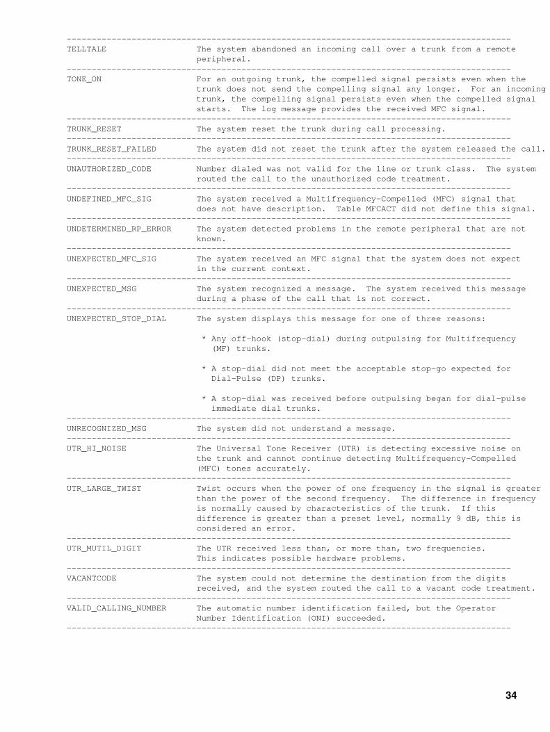
−−−−−−−−−−−−−−−−−−−−−−−−−−−−−−−−−−−−−−−−−−−−−−−−−−−−−−−−−−−−−−−−−−−−−−−−−−−−−−−−−−−−−−−−−TELLTALE The system abandoned an incoming call over a trunk from a remote peripheral.−−−−−−−−−−−−−−−−−−−−−−−−−−−−−−−−−−−−−−−−−−−−−−−−−−−−−−−−−−−−−−−−−−−−−−−−−−−−−−−−−−−−−−−−−TONE_ON For an outgoing trunk, the compelled signal persists even when the trunk does not send the compelling signal any longer. For an incoming trunk, the compelling signal persists even when the compelled signal starts. The log message provides the received MFC signal.−−−−−−−−−−−−−−−−−−−−−−−−−−−−−−−−−−−−−−−−−−−−−−−−−−−−−−−−−−−−−−−−−−−−−−−−−−−−−−−−−−−−−−−−−TRUNK_RESET The system reset the trunk during call processing.−−−−−−−−−−−−−−−−−−−−−−−−−−−−−−−−−−−−−−−−−−−−−−−−−−−−−−−−−−−−−−−−−−−−−−−−−−−−−−−−−−−−−−−−−TRUNK_RESET_FAILED The system did not reset the trunk after the system released the call.−−−−−−−−−−−−−−−−−−−−−−−−−−−−−−−−−−−−−−−−−−−−−−−−−−−−−−−−−−−−−−−−−−−−−−−−−−−−−−−−−−−−−−−−−UNAUTHORIZED_CODE Number dialed was not valid for the line or trunk class. The system routed the call to the unauthorized code treatment.−−−−−−−−−−−−−−−−−−−−−−−−−−−−−−−−−−−−−−−−−−−−−−−−−−−−−−−−−−−−−−−−−−−−−−−−−−−−−−−−−−−−−−−−−UNDEFINED_MFC_SIG The system received a Multifrequency−Compelled (MFC) signal that does not have description. Table MFCACT did not define this signal.−−−−−−−−−−−−−−−−−−−−−−−−−−−−−−−−−−−−−−−−−−−−−−−−−−−−−−−−−−−−−−−−−−−−−−−−−−−−−−−−−−−−−−−−−UNDETERMINED_RP_ERROR The system detected problems in the remote peripheral that are not known.−−−−−−−−−−−−−−−−−−−−−−−−−−−−−−−−−−−−−−−−−−−−−−−−−−−−−−−−−−−−−−−−−−−−−−−−−−−−−−−−−−−−−−−−−UNEXPECTED_MFC_SIG The system received an MFC signal that the system does not expect in the current context.−−−−−−−−−−−−−−−−−−−−−−−−−−−−−−−−−−−−−−−−−−−−−−−−−−−−−−−−−−−−−−−−−−−−−−−−−−−−−−−−−−−−−−−−−UNEXPECTED_MSG The system recognized a message. The system received this message during a phase of the call that is not correct.−−−−−−−−−−−−−−−−−−−−−−−−−−−−−−−−−−−−−−−−−−−−−−−−−−−−−−−−−−−−−−−−−−−−−−−−−−−−−−−−−−−−−−−−−UNEXPECTED_STOP_DIAL The system displays this message for one of three reasons:
* Any off−hook (stop−dial) during outpulsing for Multifrequency (MF) trunks.
* A stop−dial did not meet the acceptable stop−go expected for Dial−Pulse (DP) trunks.
* A stop−dial was received before outpulsing began for dial−pulse immediate dial trunks.−−−−−−−−−−−−−−−−−−−−−−−−−−−−−−−−−−−−−−−−−−−−−−−−−−−−−−−−−−−−−−−−−−−−−−−−−−−−−−−−−−−−−−−−−UNRECOGNIZED_MSG The system did not understand a message.−−−−−−−−−−−−−−−−−−−−−−−−−−−−−−−−−−−−−−−−−−−−−−−−−−−−−−−−−−−−−−−−−−−−−−−−−−−−−−−−−−−−−−−−−UTR_HI_NOISE The Universal Tone Receiver (UTR) is detecting excessive noise on the trunk and cannot continue detecting Multifrequency−Compelled (MFC) tones accurately.−−−−−−−−−−−−−−−−−−−−−−−−−−−−−−−−−−−−−−−−−−−−−−−−−−−−−−−−−−−−−−−−−−−−−−−−−−−−−−−−−−−−−−−−−UTR_LARGE_TWIST Twist occurs when the power of one frequency in the signal is greater than the power of the second frequency. The difference in frequency is normally caused by characteristics of the trunk. If this difference is greater than a preset level, normally 9 dB, this is considered an error.−−−−−−−−−−−−−−−−−−−−−−−−−−−−−−−−−−−−−−−−−−−−−−−−−−−−−−−−−−−−−−−−−−−−−−−−−−−−−−−−−−−−−−−−−UTR_MUTIL_DIGIT The UTR received less than, or more than, two frequencies. This indicates possible hardware problems.−−−−−−−−−−−−−−−−−−−−−−−−−−−−−−−−−−−−−−−−−−−−−−−−−−−−−−−−−−−−−−−−−−−−−−−−−−−−−−−−−−−−−−−−−VACANTCODE The system could not determine the destination from the digits received, and the system routed the call to a vacant code treatment.−−−−−−−−−−−−−−−−−−−−−−−−−−−−−−−−−−−−−−−−−−−−−−−−−−−−−−−−−−−−−−−−−−−−−−−−−−−−−−−−−−−−−−−−−VALID_CALLING_NUMBER The automatic number identification failed, but the Operator Number Identification (ONI) succeeded.−−−−−−−−−−−−−−−−−−−−−−−−−−−−−−−−−−−−−−−−−−−−−−−−−−−−−−−−−−−−−−−−−−−−−−−−−−−−−−−−−−−−−−−−−
34

−−−−−−−−−−−−−−−−−−−−−−−−−−−−−−−−−−−−−−−−−−−−−−−−−−−−−−−−−−−−−−−−−−−−−−−−−−−−−−−−−−−−−−−−−WRONG_ANI_REQUEST An FGB carrier encountered a trunk failure because the system received a wink instead of the expected off−hook after completing outpulsing. The DMS−100 switch takes down the call. This trouble code only occurs on trunks to FGB carriers that expect an ANI spill.−−−−−−−−−−−−−−−−−−−−−−−−−−−−−−−−−−−−−−−−−−−−−−−−−−−−−−−−−−−−−−−−−−−−−−−−−−−−−−−−−−−−−−−−−WRONG_SUPERVISORY_SIGNAL An FGB carrier encountered a trunk failure because the system received a wink instead of the expected off−hook after completing outpulsing. The DMS−100 switch takes down the call. This trouble code only occurs on trunks to FGB carriers that do not expect an ANI spill.−−−−−−−−−−−−−−−−−−−−−−−−−−−−−−−−−−−−−−−−−−−−−−−−−−−−−−−−−−−−−−−−−−−−−−−−−−−−−−−−−−−−−−−−−XPM_TRAP Sent by the International Line Group Controller (ILGC).−−−−−−−−−−−−−−−−−−−−−−−−−−−−−−−−−−−−−−−−−−−−−−−−−−−−−−−−−−−−−−−−−−−−−−−−−−−−−−−−−−−−−−−−−−End−
35

Nortel DMS−100 Log Report InformationTable H
Table H lists the standard definitions and equipment identifiers that log reports include.
−−−−−−−−−−−−−−−−−−−−−−−−−−−−−−−−−−−−−−−−−−−−−−−−−−−−−−−−−−−−−−−−−−−−−−−−−−−−−−−−−−−−−−−−−Field Value Description−−−−−−−−−−−−−−−−−−−−−−−−−−−−−−−−−−−−−−−−−−−−−−−−−−−−−−−−−−−−−−−−−−−−−−−−−−−−−−−−−−−−−−−−−CALLID 0−FFFFF Provides number uniquely identifying the call. When a demand COT test fails on an SS7 trunk, the system displays the NIL value −32768.−−−−−−−−−−−−−−−−−−−−−−−−−−−−−−−−−−−−−−−−−−−−−−−−−−−−−−−−−−−−−−−−−−−−−−−−−−−−−−−−−−−−−−−−−CKTID CLLI nnnn Identifies the circuit. If the circuit is a trunk, the Common Language Location Identifier (CLLI) and circuit number are given. Refer to 'TRKID' explanation in this table for more information.
LEN dn If the circuit is a line, the LEN and DN are given.−−−−−−−−−−−−−−−−−−−−−−−−−−−−−−−−−−−−−−−−−−−−−−−−−−−−−−−−−−−−−−−−−−−−−−−−−−−−−−−−−−−−−−−−−DN In the United Kingdom, the DN or National Subscriber Number (NSN) varies from 6−9 digits. The NSN must be formatted again to imitate the 10−digit, fixed−length DMS−100 format.
The NSN comprises three parts, the National Number Group (NNG), the Local Exchange Code (LEC), and the Local Number, which correspond to the three parts of the DMS−100 DN:
* The Service Numbering Plan Area (SNPA). * The central office code (NXX). * The extension number (XXXX).
A subscriber living in a director (large city) area has an NSN with a 2−digit NNG followed by a 3−digit LEC and a 4−digit local number.
* NNG + LEC + Local Number * 2 digits + 3 digits + 4 digits
A subscriber living in a non−director area has an NSN with a 3−digit NNG followed by a variable−length LEC and local number.
* NNG + LEC + Local Number * 3 digits + 0−2 digits + 4 digits−−−−−−−−−−−−−−−−−−−−−−−−−−−−−−−−−−−−−−−−−−−−−−−−−−−−−−−−−−−−−−−−−−−−−−−−−−−−−−−−−−−−−−−−−LEN SITE ff b/m dd cc Identifies Line Equipment Number (LEN) for lines connected to Line Module (LM) or Line Concentrating Module (LCM):
* SITE − frame location if remote LM or LCM (RLM or RLCM) are present. Otherwise, SITE = HOST. Refer to Customer
Data table SITE for site names.
* ff − LM or LCM frame (00−99). * b/m − LM bay or LCM module (0 or 1). * dd − LM drawer or LCM subgroup (00−31). * cc − line card (00−31).
LM and LCM test packs are located at SITE ff b/m 00 00.−−−−−−−−−−−−−−−−−−−−−−−−−−−−−−−−−−−−−−−−−−−−−−−−−−−−−−−−−−−−−−−−−−−−−−−−−−−−−−−−−−−−−−−−−
36

−−−−−−−−−−−−−−−−−−−−−−−−−−−−−−−−−−−−−−−−−−−−−−−−−−−−−−−−−−−−−−−−−−−−−−−−−−−−−−−−−−−−−−−−−LINKID CLLI nn Identifies a CCS7 link:
* CLLI − Common Language Location Identifier for the linkset datafilled in Customer Data table C7LKSET.
* n − link number (0−15).−−−−−−−−−−−−−−−−−−−−−−−−−−−−−−−−−−−−−−−−−−−−−−−−−−−−−−−−−−−−−−−−−−−−−−−−−−−−−−−−−−−−−−−−−Numbering The whole string of digits that may be dialed to reach a Plan local, national, or international destination. The general format of all numbering plans is:
Access Code + Prefix + Country Code + Area/Routing Code + Local Number
Access Code Allows access to another network, an attendant, or a feature. If a feature or a carrier access code is dialed, the digits that follow may not correspond to the numbering plan. A network access code (10XX or 10XXX) is required when dialing into a network other than the primary inter−LATA carrier. The PIC network available is the default.
Prefix One to three digits, provides information about the type of call being dialed. For example, the international prefix for calls that originate in North America on the network, "011" (international station−to−station unassisted calls) or "01" (international customer−dialed and operator−assisted calls). Other examples of a prefix (in North America) are "0" to get operator intercept and "1" to indicate long distance.
The default is to not dial the prefix, which normally implies a local, non−assisted call.
Country Code One to three digits, indicating the country. Not normally used for calls that originate and terminate in North America.
Area Code Also called NPA, or Numbering Plan Area. Used in North America and near neighbors ("World Zone 1") to identify an area of the country. Consists of three digits of the form NPX, where N represents a digit between 2 and 9, P is either 0 or 1, and X represents a digit between 0 and 9.
Routing Code Used outside North America to identify a location. 2−5 digits.
Local Number In North America, this consists of:
* The central office code−three digits of the form NXX, indicating the exchange within the area.
* The station number is normally four digits of the form XXXX, which identify the station to terminate.
Local Number Outside North America the local number is 2−9 digits, depending on the country or part of the country.−−−−−−−−−−−−−−−−−−−−−−−−−−−−−−−−−−−−−−−−−−−−−−−−−−−−−−−−−−−−−−−−−−−−−−−−−−−−−−−−−−−−−−−−−PEC nXnn Identifies Product Engineering Code (PEC) for a circuit pack. PEC consists of an integer, followed by an "X," followed by two integers (2−9).−−−−−−−−−−−−−−−−−−−−−−−−−−−−−−−−−−−−−−−−−−−−−−−−−−−−−−−−−−−−−−−−−−−−−−−−−−−−−−−−−−−−−−−−−
37

−−−−−−−−−−−−−−−−−−−−−−−−−−−−−−−−−−−−−−−−−−−−−−−−−−−−−−−−−−−−−−−−−−−−−−−−−−−−−−−−−−−−−−−−−PMID TYPE loctxt Identifies a Peripheral Module (PM).
For a description of the DMS−100 Family PMs, refer to the Peripheral Modules Maintenance Reference Manual. The value of "loctxt" for most PMs is the node number (0−2047). This number is associated with the PM through datafill in the local office.
A few PMs, including LMs, LCMs, DLMs, RCCs, RSCs, provide more detailed information about their location. OPMs will also appear in this format. In these occurrences, the value of "loctxt" is "SITE ff b" where:
* SITE − If the remote option is present, site is the location name, consisting of four characters, the first of which must be alphabetical, the rest of which are alphanumeric. Refer to Customer Data table SITE for site names.
If the remote option is not present, the site is blank.
* ff − frame (00−99). * b/m − bay or module (0 or 1).
Note: Because the LM is a two−bay frame, the value of ff refers to both bays, and the value of b/m identifies which of the two bays is involved. With the other PMs of this type, the value of ff refers to the functional bay, and the value of b/m refers to the top (1) or bottom (0) module. If the LCM is in an RLCM or an OPM, the value of m can only be 0.−−−−−−−−−−−−−−−−−−−−−−−−−−−−−−−−−−−−−−−−−−−−−−−−−−−−−−−−−−−−−−−−−−−−−−−−−−−−−−−−−−−−−−−−−RECID aaaaaannnn Provides receiver identification.
* aaaaaa − Six−character Automatic Identification of Outward Dialing (AIOD) group name.
* nnnn − Four−character number that provides identification for members of the AIOD group.−−−−−−−−−−−−−−−−−−−−−−−−−−−−−−−−−−−−−−−−−−−−−−−−−−−−−−−−−−−−−−−−−−−−−−−−−−−−−−−−−−−−−−−−−ROUTEID CLLI n Identifies a CCS7 route.
* CLLI − Common Language Location Identifier for the routeset datafilled in Customer Data table C7RTESET.
* n − route number (1−3).−−−−−−−−−−−−−−−−−−−−−−−−−−−−−−−−−−−−−−−−−−−−−−−−−−−−−−−−−−−−−−−−−−−−−−−−−−−−−−−−−−−−−−−−−TASKID hhhhhhhh tasknm Identifies call processing task or procedure.
* hh − process identification (0−FFFFFFFF). * tasknm − procedure name (character string).−−−−−−−−−−−−−−−−−−−−−−−−−−−−−−−−−−−−−−−−−−−−−−−−−−−−−−−−−−−−−−−−−−−−−−−−−−−−−−−−−−−−−−−−−TRKID CLLI nnnn Identifies trunk equipment.
* CLLI − Common Language Location Identifier for trunk group datafilled in Customer Data table CLLI. List CLLI from CI MAP level for office CLLI.
* nnnn − Circuit number for trunk in CLLI group (0−9999).−−−−−−−−−−−−−−−−−−−−−−−−−−−−−−−−−−−−−−−−−−−−−−−−−−−−−−−−−−−−−−−−−−−−−−−−−−−−−−−−−−−−−−−−−−End−
38

Nortel DMS−100 Log Report InformationTable I
Table I lists the call treatment codes that log reports include.
−−−−−−−−−−−−−−−−−−−−−−−−−−−−−−−−−−−−−−−−−−−−−−−−−−−−−−−−−−−−−−−−−−−−−−−−−−−−−−−−−−−−−−−−−Table I: DMS−100 Call Treatments
Code Treatment−−−−−−−−−−−−−−−−−−−−−−−−−−−−−−−−−−−−−−−−−−−−−−−−−−−−−−−−−−−−−−−−−−−−−−−−−−−−−−−−−−−−−−−−−ADBF ANI_DATABASE_FAILURE AIFL AIOD_FAILURE ANBB ANI_FGB_BLOCK ANCT MACHINE_INTERCEPT ANIA ANI_ACCOUNT_STATUS_NOT_ALLOWED ANTO ANSWER_TIMEOUT ATBS ATTENDANT_BUSY ATDT ATD_TIMEOUT BLDN BLANK_DIR_NUMBER BLPR BLOCKED_PRECEDENCE_CALL BUSY BUSY_LINE CACE CARR_ACC_CODE_ERROR CCNA CALLING_CARD_NOT_ALLOWED CCNV CALLING_CARD_INVALID CCTO CALLING_CARD_TIMEOUT CFWV CFW_VERIFICATIONCGRO CUSTOMER_GROUP_RESOURCE_OVERFLOW CNDT COIN_DENIED_TERM CNOT COIN_OVERTIME_TRTMT CONF CONFIRM_TONE CONP CONNECTION_NOT_POSSIBLE CQOV CAMA_QUEUE_OVFL DACD DIAL_ACCESS_CODE DCFC DISALLOWED_COIN_FREE_CALL DISC DISCONNECT_TIMEOUT_TRTMT DNTR DENIED_TERMINATION DODT DENY_ORIG_DATA_TERMINAL D950 DIAL_950 EMR1 EMERGENCY_1 EMR2 EMERGENCY_2 EMR3 EMERGENCY_3 EMR4 EMERGENCY_4 EMR5 EMERGENCY_5 EMR6 EMERGENCY_6 ERDS TRUNK_PERM_GROUND FDER FEATURE_DATA_ERROR DFNZ FIRST_DIGIT_NOT_ZERO FECG FAR_END_CONG FNAL FEATURE_NOT_ALLOWED GNCT GENERALIZED_NO_CIRCUIT HNPI HNPA_CODE_INTERCEPT INAC INVALID_ACCOUNT_CODEINAU INVALID_AUTHORIZATION_CODE INCC INVALID_CITYCODE INOC INVALID_OIC_CODE IVCC INVALID_CORRIDOR_CALL LCAB LOCAL_CALL_AREA_BARRED MANL MANUAL_LINE MHLD MUSIC_ON_HOLD
39

MSCA MISDIRECTED_CAMA_CALL MSLC MISDIRECTED_LOCAL NACD NO_DIAL_ACCESS_CODE NACK FEATURE_ACTION_NACK NBLH NETWORK_BLK_HVY_TRAFFIC NBLN NETWORK_BLK_NML_TRAFFIC NCFL NCS_COMMUNICATION_FAILURE NCII NCS_INVALID_ID_CODE NCIX NCS_INCOMING_EXCLUSION NCRT NO_CRKT NCTF NCS_TRANSLATION_FAILURE NCUN NCS_UNEXPECTED_ERROR NECG NEAR_END_CONG NINT CHANGED_NUM_INTERCEPT NMZN NO_METERING_ZONE NOCN NO_COIN NONT NOT_ON_NETWORK NOSC NO_SERVICE_CRKT NOSR NO_SOFTWARE_RESOURCEN950 NO_DIAL_950 OLRS INTER_LATA_RES OPRT REGULAR_INTERCEPT ORAC ORIG_REV_CODED ORAF ORIG_REV_FREQ ORMC ORIG_REV_MULTI_CODED ORMF ORIG_REV_MULTI_FREQ ORSS ORIG_SUSP_SERV PDIL PARTIAL_DIAL PGTO MOBILE_PAGE_TIMEOUT PMPT PREEMPT_TONE PNOH PERM_SIGN_NO_ROH PRSC PRIORITY_SCREEN_FAIL PSIG PERM_SIGNAL PTOF PREMATURE_TRUNK_OFFERING RODR REORDER RRPA REV_RING_PFXA RSDT RESTRICTED_DATE_TIME SORD STORAGE_OVERFLOW_REORDER SRRR SINGLE_REV_RING SSTO START_SIGNAL_TIME_OUT STOB SIGNAL_TIME_OUT_BOC STOC SIGNAL_TIME_OUT_IC_INC SYFL SYSTEM_FAILURE TDBR TESTDESK_BRIDGED TDND TOLL_DENIEDTESS TERM_SUSP_SERV TINV TEMPORARILY_INVALID TOVD TOLL_OVERLOAD TRBL TROUBLE_INTERCEPT TRRF TERM_REV_FREQ UMOB UNREGISTERED_MOBILE UNCA UNAUTHORIZED_CAMA_CODE UNDN UNASSIGNED_NUMBER UDNT UNDEFINED_TRTMT UNIN UNAUTHORIZED_INWATS UNOW UNAUTHORIZED_OUTWATS UNPR UNAUTHORIZED_PRECEDENCE VACS VACANT_SPEED_NUMBER VACT VACANT_CODE VCCT VACANT_COUNTRY_CODE−−−−−−−−−−−−−−−−−−−−−−−−−−−−−−−−−−−−−−−−−−−−−−−−−−−−−−−−−−−−−−−−−−−−−−−−−−−−−−−−−−−−−−−−−−End−
40

Nortel DMS−100 Log Report InformationTable J
Table J lists and explains the trunk diagnostic results that log reports include.
−−−−−−−−−−−−−−−−−−−−−−−−−−−−−−−−−−−−−−−−−−−−−−−−−−−−−−−−−−−−−−−−−−−−−−−−−−−−−−−−−−−−−−−−−Table J: DMS−100 Trunk Diagnostic Results
Diagnostic Results Description−−−−−−−−−−−−−−−−−−−−−−−−−−−−−−−−−−−−−−−−−−−−−−−−−−−−−−−−−−−−−−−−−−−−−−−−−−−−−−−−−−−−−−−−−ACTIVE TABLE FULL Indicates the system called more trunk tests to execute at the same time than the current setting in Customer Data table ATTSCHED permits.
Action: Change number of simultaneous tests from ATT MAP level.−−−−−−−−−−−−−−−−−−−−−−−−−−−−−−−−−−−−−−−−−−−−−−−−−−−−−−−−−−−−−−−−−−−−−−−−−−−−−−−−−−−−−−−−−BUSY TONE Indicates the far−end office returned a busy tone.
Action: Retry test.−−−−−−−−−−−−−−−−−−−−−−−−−−−−−−−−−−−−−−−−−−−−−−−−−−−−−−−−−−−−−−−−−−−−−−−−−−−−−−−−−−−−−−−−−CALL FAILURE MESSAGE RCVD Call Failure Message received during testing.
Action: If the call failure message continues, coordinate analysis of signaling with far−end office.−−−−−−−−−−−−−−−−−−−−−−−−−−−−−−−−−−−−−−−−−−−−−−−−−−−−−−−−−−−−−−−−−−−−−−−−−−−−−−−−−−−−−−−−−CARD FAULT Indicates a hardware error in the circuit pack.
Action: Replace circuit pack.−−−−−−−−−−−−−−−−−−−−−−−−−−−−−−−−−−−−−−−−−−−−−−−−−−−−−−−−−−−−−−−−−−−−−−−−−−−−−−−−−−−−−−−−−CONFUSION MESSAGE RCVD Confusion message received during testing.
Action: Coordinate analysis of signaling with far−end office if the confusion message persists.−−−−−−−−−−−−−−−−−−−−−−−−−−−−−−−−−−−−−−−−−−−−−−−−−−−−−−−−−−−−−−−−−−−−−−−−−−−−−−−−−−−−−−−−−CONNECTION FAILURE Indicates a connection failure between trunk and test equipment.
Action: Diagnose trunk test equipment.−−−−−−−−−−−−−−−−−−−−−−−−−−−−−−−−−−−−−−−−−−−−−−−−−−−−−−−−−−−−−−−−−−−−−−−−−−−−−−−−−−−−−−−−−COULDN'T OPEN ATTOPTNS Indicates a software bug blocked opening of access to
Customer Data table ATTOPTNS.
Action: Retry test.−−−−−−−−−−−−−−−−−−−−−−−−−−−−−−−−−−−−−−−−−−−−−−−−−−−−−−−−−−−−−−−−−−−−−−−−−−−−−−−−−−−−−−−−−COULDN'T READ ATTOPTNS Indicates required entry in Customer Data table ATTOPTNS is not present for specified test class.
Action: Check trunk and test parameters and options. Retry test.−−−−−−−−−−−−−−−−−−−−−−−−−−−−−−−−−−−−−−−−−−−−−−−−−−−−−−−−−−−−−−−−−−−−−−−−−−−−−−−−−−−−−−−−−CSC MTCE IN PROGRESS Indicates an attempt made to perform a cellular trunk test during maintenance of cell site controller.
Action: Retry test.−−−−−−−−−−−−−−−−−−−−−−−−−−−−−−−−−−−−−−−−−−−−−−−−−−−−−−−−−−−−−−−−−−−−−−−−−−−−−−−−−−−−−−−−−DATA FAULT Indicates problem with received test result data.
Action: Retry test.−−−−−−−−−−−−−−−−−−−−−−−−−−−−−−−−−−−−−−−−−−−−−−−−−−−−−−−−−−−−−−−−−−−−−−−−−−−−−−−−−−−−−−−−−
41

−−−−−−−−−−−−−−−−−−−−−−−−−−−−−−−−−−−−−−−−−−−−−−−−−−−−−−−−−−−−−−−−−−−−−−−−−−−−−−−−−−−−−−−−−DIAGNOSTIC NOT ALLOWED Indicates system initiated the test on a circuit that was not equipped for the test type.
Action: Check trunk and test parameters and options.−−−−−−−−−−−−−−−−−−−−−−−−−−−−−−−−−−−−−−−−−−−−−−−−−−−−−−−−−−−−−−−−−−−−−−−−−−−−−−−−−−−−−−−−DIAL TONE Indicates far−end office returned dial tone.
Action: Retry test.−−−−−−−−−−−−−−−−−−−−−−−−−−−−−−−−−−−−−−−−−−−−−−−−−−−−−−−−−−−−−−−−−−−−−−−−−−−−−−−−−−−−−−−−−FACILITY FAULT Indicates defect in transmission facilities.
Action: Diagnose trunk and test equipment.−−−−−−−−−−−−−−−−−−−−−−−−−−−−−−−−−−−−−−−−−−−−−−−−−−−−−−−−−−−−−−−−−−−−−−−−−−−−−−−−−−−−−−−−−FAILED TO OPEN TTT Indicates failure to open test trunk for tone generation after selection of correct trunk test equipment to connect to.
Action: Make sure in−service trunk test equipment that functions correctly is available.−−−−−−−−−−−−−−−−−−−−−−−−−−−−−−−−−−−−−−−−−−−−−−−−−−−−−−−−−−−−−−−−−−−−−−−−−−−−−−−−−−−−−−−−−FAILED TO RUN DIAGNOSTIC Indicates test equipment was not available or did not operate.
Action: Diagnose trunk and test equipment.−−−−−−−−−−−−−−−−−−−−−−−−−−−−−−−−−−−−−−−−−−−−−−−−−−−−−−−−−−−−−−−−−−−−−−−−−−−−−−−−−−−−−−−−−FAILED TO RUN TESTLINE Indicates test failed to run as a result of a software bug during initial setup. Normally indicates processes are not available.
Action: Retry test.−−−−−−−−−−−−−−−−−−−−−−−−−−−−−−−−−−−−−−−−−−−−−−−−−−−−−−−−−−−−−−−−−−−−−−−−−−−−−−−−−−−−−−−−−GROUP CURRENTLY UNDER TEST Indicates trunk group executed a trunk test. The trunk group ignores the second test request.
Action: There is no action required.−−−−−−−−−−−−−−−−−−−−−−−−−−−−−−−−−−−−−−−−−−−−−−−−−−−−−−−−−−−−−−−−−−−−−−−−−−−−−−−−−−−−−−−−−GROUP MANUAL ABORT Indicates the user performed one of the following to abort a test manually from the ATT MAP level:
* Stopped group test. * Reduced the number of simultaneous tests ATT can execute. * Used the HaltATT command to stop all ATT tests.
Action: There is no action required.−−−−−−−−−−−−−−−−−−−−−−−−−−−−−−−−−−−−−−−−−−−−−−−−−−−−−−−−−−−−−−−−−−−−−−−−−−−−−−−−−−−−−−−−−GROUP SYSTEM ABORT: Indicates five consecutive failures. The system retested the REFERENCE TRUNK FAILURE reference trunk. The reference trunk failed the second test. The system aborts the group.
Action: Diagnose trunk testing equipment and reference trunks.−−−−−−−−−−−−−−−−−−−−−−−−−−−−−−−−−−−−−−−−−−−−−−−−−−−−−−−−−−−−−−−−−−−−−−−−−−−−−−−−−−−−−−−−−GROUP SYSTEM ABORT: Indicates five consecutive failures. The system retested the REFERENCE TRUNK UNAVAILABLE reference trunk. The reference trunk failed the second test. The system aborts the group.
Action: Diagnose trunk testing equipment and reference trunks.−−−−−−−−−−−−−−−−−−−−−−−−−−−−−−−−−−−−−−−−−−−−−−−−−−−−−−−−−−−−−−−−−−−−−−−−−−−−−−−−−−−−−−−−−GROUP SYSTEM ABORT: This diagnostic indicates five consecutive failures during CONSECUTIVE FAILURES search for a group reference trunk.
Action: Diagnose trunk test equipment.−−−−−−−−−−−−−−−−−−−−−−−−−−−−−−−−−−−−−−−−−−−−−−−−−−−−−−−−−−−−−−−−−−−−−−−−−−−−−−−−−−−−−−−−−
42

−−−−−−−−−−−−−−−−−−−−−−−−−−−−−−−−−−−−−−−−−−−−−−−−−−−−−−−−−−−−−−−−−−−−−−−−−−−−−−−−−−−−−−−−−HARDWARE FAILURE This diagnostic indicates a hardware error detected in the trunk circuit.
Action: Diagnose trunk under test for a hardware defect.−−−−−−−−−−−−−−−−−−−−−−−−−−−−−−−−−−−−−−−−−−−−−−−−−−−−−−−−−−−−−−−−−−−−−−−−−−−−−−−−−−−−−−−−−HIGH−DRY Indicates far−end office did not send an off−hook signal after a burst of audible ringing tone.
Action: Diagnose trunk under test. If diagnostics pass, error is in far−end or transmission facility.−−−−−−−−−−−−−−−−−−−−−−−−−−−−−−−−−−−−−−−−−−−−−−−−−−−−−−−−−−−−−−−−−−−−−−−−−−−−−−−−−−−−−−−−−HIGH TONE Indicates far−end office returned a high frequency tone.
Action: Retry test.−−−−−−−−−−−−−−−−−−−−−−−−−−−−−−−−−−−−−−−−−−−−−−−−−−−−−−−−−−−−−−−−−−−−−−−−−−−−−−−−−−−−−−−−−HIT RECEIVED This diagnostic indicates the detection of a transient interruption to the trunk.
Action: Retry test.−−−−−−−−−−−−−−−−−−−−−−−−−−−−−−−−−−−−−−−−−−−−−−−−−−−−−−−−−−−−−−−−−−−−−−−−−−−−−−−−−−−−−−−−−INTEGRITY LOST MESSAGE RCVD Integrity lost message received during testing.
Action: High occurrences can indicate a problem with the network. Check for correctly functioning hardware.−−−−−−−−−−−−−−−−−−−−−−−−−−−−−−−−−−−−−−−−−−−−−−−−−−−−−−−−−−−−−−−−−−−−−−−−−−−−−−−−−−−−−−−−−INVALID REPLY Indicates far−end office returned an invalid signal when the DMS−100 tried to outpulse digits.
Action: Diagnose trunk under test. If diagnostics pass, fault is in far−end or transmission facility.−−−−−−−−−−−−−−−−−−−−−−−−−−−−−−−−−−−−−−−−−−−−−−−−−−−−−−−−−−−−−−−−−−−−−−−−−−−−−−−−−−−−−−−−−LOCKOUT MESSAGE RCVD Lockout message received during testing.
Action: If lockout message continues, coordinate analysis into signaling with far end office.−−−−−−−−−−−−−−−−−−−−−−−−−−−−−−−−−−−−−−−−−−−−−−−−−−−−−−−−−−−−−−−−−−−−−−−−−−−−−−−−−−−−−−−−−LOOP SIG FAULT Indicates a fault in the loop bridge or receiving equipment causes signaling failure.
Action: Diagnose test equipment.−−−−−−−−−−−−−−−−−−−−−−−−−−−−−−−−−−−−−−−−−−−−−−−−−−−−−−−−−−−−−−−−−−−−−−−−−−−−−−−−−−−−−−−−−LOOP SIG FAULT NOSET Indicates a fault in the software or loop generating equipment causes a signaling failure.
Action: Check trunk and test parameters and options. Diagnose test equipment.−−−−−−−−−−−−−−−−−−−−−−−−−−−−−−−−−−−−−−−−−−−−−−−−−−−−−−−−−−−−−−−−−−−−−−−−−−−−−−−−−−−−−−−−−LTA CANCELLED Indicates Local Trunk Alarm (LTA) was not cancelled correctly.
Action: Diagnose test equipment. Retry test.−−−−−−−−−−−−−−−−−−−−−−−−−−−−−−−−−−−−−−−−−−−−−−−−−−−−−−−−−−−−−−−−−−−−−−−−−−−−−−−−−−−−−−−−−LTU FAULT Indicates detection of fault in Line Test Unit (LTU).
Action: Diagnose LTU.−−−−−−−−−−−−−−−−−−−−−−−−−−−−−−−−−−−−−−−−−−−−−−−−−−−−−−−−−−−−−−−−−−−−−−−−−−−−−−−−−−−−−−−−MILLIWATT Indicates far−end office returned a milliwatt tone.
Action: Retry test.−−−−−−−−−−−−−−−−−−−−−−−−−−−−−−−−−−−−−−−−−−−−−−−−−−−−−−−−−−−−−−−−−−−−−−−−−−−−−−−−−−−−−−−−−
43

−−−−−−−−−−−−−−−−−−−−−−−−−−−−−−−−−−−−−−−−−−−−−−−−−−−−−−−−−−−−−−−−−−−−−−−−−−−−−−−−−−−−−−−−−NO/BAD CSC RESPONSE Indicates an attempt was made to perform a cellular trunk test. The Cell Site Controller (CSC) did not send a response, or sent a response that was not expected.
Action: Diagnose CSC.−−−−−−−−−−−−−−−−−−−−−−−−−−−−−−−−−−−−−−−−−−−−−−−−−−−−−−−−−−−−−−−−−−−−−−−−−−−−−−−−−−−−−−−−−NO/BAD RCU RESPONSE Indicates an attempt was made to perform a cellular trunk test. The cellular Remote Carrier Unit (RCU) did not send a response or sent a response that was not expected.
Action: Diagnose RCU.−−−−−−−−−−−−−−−−−−−−−−−−−−−−−−−−−−−−−−−−−−−−−−−−−−−−−−−−−−−−−−−−−−−−−−−−−−−−−−−−−−−−−−−−−NO/BAD TAU RESPOSE Indicates an attempt was made to perform a cellular trunk test. The cellular Test and Alarm Unit (TAU) did not send a response, or sent a response that was not expected.
Action: Diagnose TAU.−−−−−−−−−−−−−−−−−−−−−−−−−−−−−−−−−−−−−−−−−−−−−−−−−−−−−−−−−−−−−−−−−−−−−−−−−−−−−−−−−−−−−−−−−NO CARD IN SHELF Indicates circuit pack missing.
Action: Check installation for trunk circuit equipment.−−−−−−−−−−−−−−−−−−−−−−−−−−−−−−−−−−−−−−−−−−−−−−−−−−−−−−−−−−−−−−−−−−−−−−−−−−−−−−−−−−−−−−−−−NO FAR END TEST EQUIPMENT Indicates far−end test equipment was not available or is not present.
Action: Diagnose trunk under test. If diagnostics pass, fault is in far−end or transmission facility.−−−−−−−−−−−−−−−−−−−−−−−−−−−−−−−−−−−−−−−−−−−−−−−−−−−−−−−−−−−−−−−−−−−−−−−−−−−−−−−−−−−−−−−−−NO LOGICAL MB Indicates software bug prevented allocation of no logical Message Buffer (MB).
Action: Retry test.−−−−−−−−−−−−−−−−−−−−−−−−−−−−−−−−−−−−−−−−−−−−−−−−−−−−−−−−−−−−−−−−−−−−−−−−−−−−−−−−−−−−−−−−−NO START DIAL SIGNAL Indicates far−end office did not respond after trunk was seized.
Action: Retry test.−−−−−−−−−−−−−−−−−−−−−−−−−−−−−−−−−−−−−−−−−−−−−−−−−−−−−−−−−−−−−−−−−−−−−−−−−−−−−−−−−−−−−−−−−NO TEST EQUIPMENT Indicates test equipment was not available.
Action: Check trunk and test parameters and options.−−−−−−−−−−−−−−−−−−−−−−−−−−−−−−−−−−−−−−−−−−−−−−−−−−−−−−−−−−−−−−−−−−−−−−−−−−−−−−−−−−−−−−−−−NO TESTLINE NUMBER Indicates a software bug prevented the trunk circuit from detection.
Action: Check trunk and test parameters and options. Retry test.−−−−−−−−−−−−−−−−−−−−−−−−−−−−−−−−−−−−−−−−−−−−−−−−−−−−−−−−−−−−−−−−−−−−−−−−−−−−−−−−−−−−−−−−−NO TONE Indicates far−end office failed to return the correct tone.
Action: Retry test.−−−−−−−−−−−−−−−−−−−−−−−−−−−−−−−−−−−−−−−−−−−−−−−−−−−−−−−−−−−−−−−−−−−−−−−−−−−−−−−−−−−−−−−−NO TRUNKS IN GROUP Indicates a software bug prevented detection of trunks in group.
Action: Check trunk and test parameters and options. Retry test.−−−−−−−−−−−−−−−−−−−−−−−−−−−−−−−−−−−−−−−−−−−−−−−−−−−−−−−−−−−−−−−−−−−−−−−−−−−−−−−−−−−−−−−−−NOT OG OR 2W TRUNK GROUP Indicates the test attempted transmission or lost tests on a trunk that is not an outgoing or two−wire trunk.
Action: Check trunk and test parameters and options.−−−−−−−−−−−−−−−−−−−−−−−−−−−−−−−−−−−−−−−−−−−−−−−−−−−−−−−−−−−−−−−−−−−−−−−−−−−−−−−−−−−−−−−−−
44
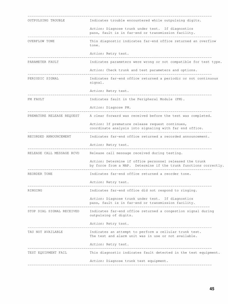
−−−−−−−−−−−−−−−−−−−−−−−−−−−−−−−−−−−−−−−−−−−−−−−−−−−−−−−−−−−−−−−−−−−−−−−−−−−−−−−−−−−−−−−−−OUTPULSING TROUBLE Indicates trouble encountered while outpulsing digits.
Action: Diagnose trunk under test. If diagnostics pass, fault is in far−end or transmission facility.−−−−−−−−−−−−−−−−−−−−−−−−−−−−−−−−−−−−−−−−−−−−−−−−−−−−−−−−−−−−−−−−−−−−−−−−−−−−−−−−−−−−−−−−−OVERFLOW TONE This diagnostic indicates far−end office returned an overflow tone.
Action: Retry test.−−−−−−−−−−−−−−−−−−−−−−−−−−−−−−−−−−−−−−−−−−−−−−−−−−−−−−−−−−−−−−−−−−−−−−−−−−−−−−−−−−−−−−−−−PARAMETER FAULT Indicates parameters were wrong or not compatible for test type.
Action: Check trunk and test parameters and options.−−−−−−−−−−−−−−−−−−−−−−−−−−−−−−−−−−−−−−−−−−−−−−−−−−−−−−−−−−−−−−−−−−−−−−−−−−−−−−−−−−−−−−−−−PERIODIC SIGNAL Indicates far−end office returned a periodic or not continuous signal.
Action: Retry test.−−−−−−−−−−−−−−−−−−−−−−−−−−−−−−−−−−−−−−−−−−−−−−−−−−−−−−−−−−−−−−−−−−−−−−−−−−−−−−−−−−−−−−−−−PM FAULT Indicates fault in the Peripheral Module (PM).
Action: Diagnose PM.−−−−−−−−−−−−−−−−−−−−−−−−−−−−−−−−−−−−−−−−−−−−−−−−−−−−−−−−−−−−−−−−−−−−−−−−−−−−−−−−−−−−−−−−−PREMATURE RELEASE REQUEST A clear forward was received before the test was completed.
Action: If premature release request continues, coordinate analysis into signaling with far end office.−−−−−−−−−−−−−−−−−−−−−−−−−−−−−−−−−−−−−−−−−−−−−−−−−−−−−−−−−−−−−−−−−−−−−−−−−−−−−−−−−−−−−−−−−RECORDED ANNOUNCEMENT Indicates far−end office returned a recorded announcement.
Action: Retry test.−−−−−−−−−−−−−−−−−−−−−−−−−−−−−−−−−−−−−−−−−−−−−−−−−−−−−−−−−−−−−−−−−−−−−−−−−−−−−−−−−−−−−−−−−RELEASE CALL MESSAGE RCVD Release call message received during testing.
Action: Determine if office personnel released the trunk by force from a MAP. Determine if the trunk functions correctly.−−−−−−−−−−−−−−−−−−−−−−−−−−−−−−−−−−−−−−−−−−−−−−−−−−−−−−−−−−−−−−−−−−−−−−−−−−−−−−−−−−−−−−−−−REORDER TONE Indicates far−end office returned a reorder tone.
Action: Retry test.−−−−−−−−−−−−−−−−−−−−−−−−−−−−−−−−−−−−−−−−−−−−−−−−−−−−−−−−−−−−−−−−−−−−−−−−−−−−−−−−−−−−−−−−−RINGING Indicates far−end office did not respond to ringing.
Action: Diagnose trunk under test. If diagnostics pass, fault is in far−end or transmission facility.−−−−−−−−−−−−−−−−−−−−−−−−−−−−−−−−−−−−−−−−−−−−−−−−−−−−−−−−−−−−−−−−−−−−−−−−−−−−−−−−−−−−−−−−STOP DIAL SIGNAL RECEIVED Indicates far−end office returned a congestion signal during outpulsing of digits.
Action: Retry test.−−−−−−−−−−−−−−−−−−−−−−−−−−−−−−−−−−−−−−−−−−−−−−−−−−−−−−−−−−−−−−−−−−−−−−−−−−−−−−−−−−−−−−−−−TAU NOT AVAILABLE Indicates an attempt to perform a cellular trunk test. The test and alarm unit was in use or not available.
Action: Retry test.−−−−−−−−−−−−−−−−−−−−−−−−−−−−−−−−−−−−−−−−−−−−−−−−−−−−−−−−−−−−−−−−−−−−−−−−−−−−−−−−−−−−−−−−−TEST EQUIPMENT FAIL This diagnostic indicates fault detected in the test equipment.
Action: Diagnose trunk test equipment.−−−−−−−−−−−−−−−−−−−−−−−−−−−−−−−−−−−−−−−−−−−−−−−−−−−−−−−−−−−−−−−−−−−−−−−−−−−−−−−−−−−−−−−−−
45

−−−−−−−−−−−−−−−−−−−−−−−−−−−−−−−−−−−−−−−−−−−−−−−−−−−−−−−−−−−−−−−−−−−−−−−−−−−−−−−−−−−−−−−−−TEST EQUIPMENT FAULT Indicates fault was detected in test equipment.
Action: Diagnose trunk test equipment.−−−−−−−−−−−−−−−−−−−−−−−−−−−−−−−−−−−−−−−−−−−−−−−−−−−−−−−−−−−−−−−−−−−−−−−−−−−−−−−−−−−−−−−−−TEST EQUIPMENT UNAVAILABLE Indicates test equipment was not available for test. The system generates this report every ten minutes until the test equipment is available.
Action: No required action.−−−−−−−−−−−−−−−−−−−−−−−−−−−−−−−−−−−−−−−−−−−−−−−−−−−−−−−−−−−−−−−−−−−−−−−−−−−−−−−−−−−−−−−−−TEST NOT ALLOWED Indicates test is not allowed on circuit.
Action: Check trunk and test parameters and options.−−−−−−−−−−−−−−−−−−−−−−−−−−−−−−−−−−−−−−−−−−−−−−−−−−−−−−−−−−−−−−−−−−−−−−−−−−−−−−−−−−−−−−−−−TEST PROCESS TROUBLE Indicates trouble with test process.
Action: Retry test.−−−−−−−−−−−−−−−−−−−−−−−−−−−−−−−−−−−−−−−−−−−−−−−−−−−−−−−−−−−−−−−−−−−−−−−−−−−−−−−−−−−−−−−−−TEST PROTOCOL TROUBLE Indicates a software bug or the far−end office sent a response that was not expected.
Action: Retry test.−−−−−−−−−−−−−−−−−−−−−−−−−−−−−−−−−−−−−−−−−−−−−−−−−−−−−−−−−−−−−−−−−−−−−−−−−−−−−−−−−−−−−−−−−TESTLINE NOT AVAILABLE Indicates the test is not available in current load.
Action: Check trunk and test parameters and options.−−−−−−−−−−−−−−−−−−−−−−−−−−−−−−−−−−−−−−−−−−−−−−−−−−−−−−−−−−−−−−−−−−−−−−−−−−−−−−−−−−−−−−−−−TONE DETECTION FAILED Indicates failure to detect correct tone.
Action: Diagnose trunk test equipment.−−−−−−−−−−−−−−−−−−−−−−−−−−−−−−−−−−−−−−−−−−−−−−−−−−−−−−−−−−−−−−−−−−−−−−−−−−−−−−−−−−−−−−−−−TPT TONE Indicates far−end office unexpectedly returned a Test Progress Tone (TPT).
Action: Retry test.−−−−−−−−−−−−−−−−−−−−−−−−−−−−−−−−−−−−−−−−−−−−−−−−−−−−−−−−−−−−−−−−−−−−−−−−−−−−−−−−−−−−−−−−−TRUNK GROUP TIMEOUT Indicates time expired waiting for each trunk in the trunk group to become available for testing. The Customer Data table ATTSCHED shows the allowed time to wait for trunks to become available.
Action: Check WAIT_TIME in customer data table ATTSCHED. Retry test.−−−−−−−−−−−−−−−−−−−−−−−−−−−−−−−−−−−−−−−−−−−−−−−−−−−−−−−−−−−−−−−−−−−−−−−−−−−−−−−−−−−−−−−−−TRUNK NOT TESTED CFL Indicates trunk circuit was not tested because it was carrier−failed.
Action: Contact the next level of maintenance.−−−−−−−−−−−−−−−−−−−−−−−−−−−−−−−−−−−−−−−−−−−−−−−−−−−−−−−−−−−−−−−−−−−−−−−−−−−−−−−−−−−−−−−−−TRUNK NOT TESTED CPD Indicates trunk circuit was not tested because it was call processing deloaded.
Action: Retry test when trunk state returns to IDLE,−−−−−−−−−−−−−−−−−−−−−−−−−−−−−−−−−−−−−−−−−−−−−−−−−−−−−−−−−−−−−−−−−−−−−−−−−−−−−−−−−−−−−−−−−TRUNK NOT TESTED CPB Indicates trunk circuit was not tested because it was call processing busy.
Action: Retry test when trunk state returns IDLE.−−−−−−−−−−−−−−−−−−−−−−−−−−−−−−−−−−−−−−−−−−−−−−−−−−−−−−−−−−−−−−−−−−−−−−−−−−−−−−−−−−−−−−−−−TRUNK NOT TESTED DEL Indicates the deloaded trunk circuit is not tested.
Action: Return trunk to service. Retry test.−−−−−−−−−−−−−−−−−−−−−−−−−−−−−−−−−−−−−−−−−−−−−−−−−−−−−−−−−−−−−−−−−−−−−−−−−−−−−−−−−−−−−−−−−
46
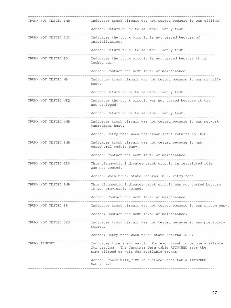
−−−−−−−−−−−−−−−−−−−−−−−−−−−−−−−−−−−−−−−−−−−−−−−−−−−−−−−−−−−−−−−−−−−−−−−−−−−−−−−−−−−−−−−−−TRUNK NOT TESTED IMB Indicates trunk circuit was not tested because it was offline.
Action: Return trunk to service. Retry test.−−−−−−−−−−−−−−−−−−−−−−−−−−−−−−−−−−−−−−−−−−−−−−−−−−−−−−−−−−−−−−−−−−−−−−−−−−−−−−−−−−−−−−−−−TRUNK NOT TESTED INI Indicates the trunk circuit is not tested because of initialization.
Action: Return trunk to service. Retry test.−−−−−−−−−−−−−−−−−−−−−−−−−−−−−−−−−−−−−−−−−−−−−−−−−−−−−−−−−−−−−−−−−−−−−−−−−−−−−−−−−−−−−−−−−TRUNK NOT TESTED LO Indicates the trunk circuit is not tested because it is locked out.
Action: Contact the next level of maintenance.−−−−−−−−−−−−−−−−−−−−−−−−−−−−−−−−−−−−−−−−−−−−−−−−−−−−−−−−−−−−−−−−−−−−−−−−−−−−−−−−−−−−−−−−−TRUNK NOT TESTED MB Indicates trunk circuit was not tested because it was manually busy.
Action: Return trunk to service. Retry test.−−−−−−−−−−−−−−−−−−−−−−−−−−−−−−−−−−−−−−−−−−−−−−−−−−−−−−−−−−−−−−−−−−−−−−−−−−−−−−−−−−−−−−−−−TRUNK NOT TESTED NEQ Indicates the trunk circuit was not tested because it was not equipped.
Action: Return trunk to service. Retry test.−−−−−−−−−−−−−−−−−−−−−−−−−−−−−−−−−−−−−−−−−−−−−−−−−−−−−−−−−−−−−−−−−−−−−−−−−−−−−−−−−−−−−−−−−TRUNK NOT TESTED NMB Indicates trunk circuit was not tested because it was network management busy.
Action: Retry test when the trunk state returns to IDLE.−−−−−−−−−−−−−−−−−−−−−−−−−−−−−−−−−−−−−−−−−−−−−−−−−−−−−−−−−−−−−−−−−−−−−−−−−−−−−−−−−−−−−−−−−TRUNK NOT TESTED PMB Indicates trunk circuit was not tested because it was peripheral module busy.
Action: Contact the next level of maintenance.−−−−−−−−−−−−−−−−−−−−−−−−−−−−−−−−−−−−−−−−−−−−−−−−−−−−−−−−−−−−−−−−−−−−−−−−−−−−−−−−−−−−−−−−−TRUNK NOT TESTED RES This diagnostic indicates trunk circuit in restricted idle was not tested.
Action: When trunk state returns IDLE, retry test.−−−−−−−−−−−−−−−−−−−−−−−−−−−−−−−−−−−−−−−−−−−−−−−−−−−−−−−−−−−−−−−−−−−−−−−−−−−−−−−−−−−−−−−−−TRUNK NOT TESTED RMB This diagnostic indicates trunk circuit was not tested because it was previously seized.
Action: Contact the next level of maintenance.−−−−−−−−−−−−−−−−−−−−−−−−−−−−−−−−−−−−−−−−−−−−−−−−−−−−−−−−−−−−−−−−−−−−−−−−−−−−−−−−−−−−−−−−−TRUNK NOT TESTED SB Indicates trunk circuit was not tested because it was system busy.
Action: Contact the next level of maintenance.−−−−−−−−−−−−−−−−−−−−−−−−−−−−−−−−−−−−−−−−−−−−−−−−−−−−−−−−−−−−−−−−−−−−−−−−−−−−−−−−−−−−−−−−−TRUNK NOT TESTED SZD Indicates trunk circuit was not tested because it was previously seized.
Action: Retry test when trunk state returns IDLE.−−−−−−−−−−−−−−−−−−−−−−−−−−−−−−−−−−−−−−−−−−−−−−−−−−−−−−−−−−−−−−−−−−−−−−−−−−−−−−−−−−−−−−−−−TRUNK TIMEOUT Indicates time spent waiting for each trunk to become available for testing. The Customer Data table ATTSCHED sets the time allowed to wait for available trunks.
Action: Check WAIT_TIME in customer data table ATTSCHED. Retry test.−−−−−−−−−−−−−−−−−−−−−−−−−−−−−−−−−−−−−−−−−−−−−−−−−−−−−−−−−−−−−−−−−−−−−−−−−−−−−−−−−−−−−−−−−
47
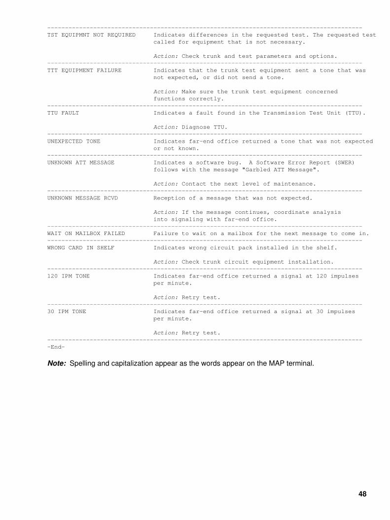
−−−−−−−−−−−−−−−−−−−−−−−−−−−−−−−−−−−−−−−−−−−−−−−−−−−−−−−−−−−−−−−−−−−−−−−−−−−−−−−−−−−−−−−−−TST EQUIPMNT NOT REQUIRED Indicates differences in the requested test. The requested test called for equipment that is not necessary.
Action: Check trunk and test parameters and options.−−−−−−−−−−−−−−−−−−−−−−−−−−−−−−−−−−−−−−−−−−−−−−−−−−−−−−−−−−−−−−−−−−−−−−−−−−−−−−−−−−−−−−−−−TTT EQUIPMENT FAILURE Indicates that the trunk test equipment sent a tone that was not expected, or did not send a tone.
Action: Make sure the trunk test equipment concerned functions correctly.−−−−−−−−−−−−−−−−−−−−−−−−−−−−−−−−−−−−−−−−−−−−−−−−−−−−−−−−−−−−−−−−−−−−−−−−−−−−−−−−−−−−−−−−−TTU FAULT Indicates a fault found in the Transmission Test Unit (TTU).
Action: Diagnose TTU.−−−−−−−−−−−−−−−−−−−−−−−−−−−−−−−−−−−−−−−−−−−−−−−−−−−−−−−−−−−−−−−−−−−−−−−−−−−−−−−−−−−−−−−−−UNEXPECTED TONE Indicates far−end office returned a tone that was not expected or not known.−−−−−−−−−−−−−−−−−−−−−−−−−−−−−−−−−−−−−−−−−−−−−−−−−−−−−−−−−−−−−−−−−−−−−−−−−−−−−−−−−−−−−−−−−UNKNOWN ATT MESSAGE Indicates a software bug. A Software Error Report (SWER) follows with the message "Garbled ATT Message".
Action: Contact the next level of maintenance.−−−−−−−−−−−−−−−−−−−−−−−−−−−−−−−−−−−−−−−−−−−−−−−−−−−−−−−−−−−−−−−−−−−−−−−−−−−−−−−−−−−−−−−−−UNKNOWN MESSAGE RCVD Reception of a message that was not expected.
Action: If the message continues, coordinate analysis into signaling with far−end office.−−−−−−−−−−−−−−−−−−−−−−−−−−−−−−−−−−−−−−−−−−−−−−−−−−−−−−−−−−−−−−−−−−−−−−−−−−−−−−−−−−−−−−−−−WAIT ON MAILBOX FAILED Failure to wait on a mailbox for the next message to come in.−−−−−−−−−−−−−−−−−−−−−−−−−−−−−−−−−−−−−−−−−−−−−−−−−−−−−−−−−−−−−−−−−−−−−−−−−−−−−−−−−−−−−−−−−WRONG CARD IN SHELF Indicates wrong circuit pack installed in the shelf.
Action: Check trunk circuit equipment installation.−−−−−−−−−−−−−−−−−−−−−−−−−−−−−−−−−−−−−−−−−−−−−−−−−−−−−−−−−−−−−−−−−−−−−−−−−−−−−−−−−−−−−−−−−120 IPM TONE Indicates far−end office returned a signal at 120 impulses per minute.
Action: Retry test.−−−−−−−−−−−−−−−−−−−−−−−−−−−−−−−−−−−−−−−−−−−−−−−−−−−−−−−−−−−−−−−−−−−−−−−−−−−−−−−−−−−−−−−−−30 IPM TONE Indicates far−end office returned a signal at 30 impulses per minute.
Action: Retry test.−−−−−−−−−−−−−−−−−−−−−−−−−−−−−−−−−−−−−−−−−−−−−−−−−−−−−−−−−−−−−−−−−−−−−−−−−−−−−−−−−−−−−−−−−−End−
Note: Spelling and capitalization appear as the words appear on the MAP terminal.
48

Nortel DMS−100 Log Report InformationTable K
Table K lists the entry codes and call types that Automatic Message Accounting (AMA) log reportsinclude.
−−−−−−−−−−−−−−−−−−−−−−−−−−−−−−−−−−−−−−−−−−−−−−−−−−−−−−−−−−−−−−−−−−−−−−−−−−−−−−−−−−−−−−−−−Entry Code Call type−−−−−−−−−−−−−−−−−−−−−−−−−−−−−−−−−−−−−−−−−−−−−−−−−−−−−−−−−−−−−−−−−−−−−−−−−−−−−−−−−−−−−−−−−00 Station Paid DDD 01 Station Paid LCDR 02−07 Reserved for Special Features 08 TWX 09 Data10−15 Reserved for special features 16 Message Rate − Timed 17 Message Rate − Not Timed 18 Detailed Message Rate 19 Conference Trunk Use 20 Station Paid Operator Assisted 21 Station Collect 22 Station Special Calling 23 Person Paid 24 Person Collect 25 Person Special Calling 26 Auto Collect 27 Station Special Called 28 Person Special Called29 Person Call Back (PCB) 30 PCB Special Billing 31−39 Not Used 40 Station Paid DDO (see Note 1)41−55 Reserved for Special Features56 Not Used 57 Not Used 58−59 Reserved for Possible Future Use 60 Station Paid Operator Assisted (see Note 1)61 Station Collect (see Note 1)62 Station Special Calling (see Note 1)63 Person Paid (see Note 1)64 Person Collect (see Note 1)65 Person Special Calling (see Note 1)66 Not Used (see Note 1)67 Station Special Called (see Note 1)68 Person Special Called (see Note 1)69 Person Call Back (PCB) (see Note 1)70 PCB Special Billing (see Note 1)71−79 Not Used80 INWATS − Measured Time 81−83 Reserved for Possible Future Use 84−89 Not Used 90 Used by LAMA First Extension Entry 91−95 Not Used 96 Not Shown (default) 97 Canceled Call (domestic) 98 Canceled Call (overseas) 99 AMA Test Call−−−−−−−−−−−−−−−−−−−−−−−−−−−−−−−−−−−−−−−−−−−−−−−−−−−−−−−−−−−−−−−−−−−−−−−−−−−−−−−−−−−−−−−−−−End−
49

Note 1: Indicates international dialing always used for calls that ACSS handled.
Note 2: The operating company can modify codes 00−99 for DMS−100 and DMS−200. Refer totable TOLLENTC in the Data Schema Reference Manual.
Note 3: For DMS−200 TOPS, codes 00−19 are the option of the operating company. Codes20−99 are hard−coded.
Note 4: Codes 00−39 and 80−99 apply to Local Automatic Message Accounting (LAMA).
Note 4: For all loads, codes 40−79 appear in log report AMAB101 as DDO=Y.
50

Nortel DMS−100 Security Log ReportsSECU101
Explanation
The Security (SECU) subsystem generates SECU101. The subsystem generates SECU101 whena valid user uses normal login/logoff procedures to log on or off of a terminal.
Format
The log report format for SECU101 is as follows:
SECU101 mmmdd hh:mm:ss ssdd INFO User: <user> logtxt <term>.
Example
An example of log report SECU101 follows:
SECU101 APR01 12:00:00 2112 INFO User: JANET logged OUT from MAP.
Field Descriptions
The following table describes each field in the log report:
−−−−−−−−−−−−−−−−−−−−−−−−−−−−−−−−−−−−−−−−−−−−−−−−−−−−−−−−−−−−−−−−−−−−−−−−−−−−−−−−−−−−−−−−−Field Value Description−−−−−−−−−−−−−−−−−−−−−−−−−−−−−−−−−−−−−−−−−−−−−−−−−−−−−−−−−−−−−−−−−−−−−−−−−−−−−−−−−−−−−−−−−INFO constant Indicates information about the SECU subsystem.
<user> descriptive text Identifies user that logged on or off of a specified terminal. Use the CI command SHOWUSERS for a list of users defined to the system.
logtxt logged IN to Identifies user that logged on the terminal.
logged OUT from Identifies user that logged off of the terminal.
<term> descriptive text Identifies the terminal where the user logged on or off. List TERMDEV from CI MAP level for list of terminals.−−−−−−−−−−−−−−−−−−−−−−−−−−−−−−−−−−−−−−−−−−−−−−−−−−−−−−−−−−−−−−−−−−−−−−−−−−−−−−−−−−−−−−−−−−End−
Action: Save the report for security personnel. (all SECU reports)
Associated OM Registers: There are no associated Operational Measurement (OM)registers. (all SECU reports)
Additional Information: There is no additional information. (all SECU reports)
51

Nortel DMS−100 Security Log ReportsSECU102
Explanation
The Security (SECU) subsystem generates SECU102. The subsystem generates SECU102 whena user uses an invalid identification or password to attempt to login on a terminal.
Format
The log report format for SECU102 is as follows:
SECU102 mmmdd hh:mm:ss ssdd INFO Invalid LOGIN attempt on <term>. USERID: <user>. reastxt.
Example
An example of log report SECU102 follows:
SECU102 APR01 12:00:00 2112 INFO Invalid LOGIN attempt on MAP. USERID: JANET. Bad password.
Field Descriptions
The following table describes each field in the log report:
−−−−−−−−−−−−−−−−−−−−−−−−−−−−−−−−−−−−−−−−−−−−−−−−−−−−−−−−−−−−−−−−−−−−−−−−−−−−−−−−−−−−−−−−−Field Value Description−−−−−−−−−−−−−−−−−−−−−−−−−−−−−−−−−−−−−−−−−−−−−−−−−−−−−−−−−−−−−−−−−−−−−−−−−−−−−−−−−−−−−−−−−INFO constant Indicates information about the SECU subsystem.
Invalid LOGIN symbolic text Identifies the terminal on which the userattempt on attempted to login. List TERMDEV from CI MAP level for list of terminals.
USERID bad userid Indicates use of invalid user identification to attempt login on terminal.
0000−FFFF Provides valid identification for a user that attempts to login the terminal. Use the CI command SHOWUSERS for a list of users defined to the system.
reastxt Bad password Indicates the user attempted to login the terminal with an invalid password.
Password expired Indicates the user attempted to login the terminal with an expired password.
Bad userid Indicates the user attempted to login the terminal with an invalid user identification.−−−−−−−−−−−−−−−−−−−−−−−−−−−−−−−−−−−−−−−−−−−−−−−−−−−−−−−−−−−−−−−−−−−−−−−−−−−−−−−−−−−−−−−−−−End−
52

Nortel DMS−100 Security Log ReportsSECU103
Explanation
The Security (SECU) subsystem generates SECU103 when one user forces another user off theterminal. Both users are logged on this terminal.
Format
The log report format for SECU103 is as follows:
SECU103 mmmdd hh:mm:ss ssdd INFO User: <user> forced out from <term>. By Command from user <usernm> on <termnm>.
Example
An example of log report SECU103 follows:
SECU103 APR01 12:00:00 2112 INFO User: JANET forced out from MAP. By Command from user OPERATOR on MAP.
Field Descriptions
The following table describes each field in the log report:
−−−−−−−−−−−−−−−−−−−−−−−−−−−−−−−−−−−−−−−−−−−−−−−−−−−−−−−−−−−−−−−−−−−−−−−−−−−−−−−−−−−−−−−−−Field Value Description−−−−−−−−−−−−−−−−−−−−−−−−−−−−−−−−−−−−−−−−−−−−−−−−−−−−−−−−−−−−−−−−−−−−−−−−−−−−−−−−−−−−−−−−−INFO constant Indicates information about the SECU subsystem.
<user> descriptive text Identifies the user forced off the terminal. Use the CI command SHOWUSERS for a list of users defined to the system.
forced out from symbolic text Identifies terminal that one user forced the other user off. List TERMDEV from CI MAP level for list of terminals.
By Command from constant Identifies the user forcing the other user off theuser terminal. Use the CI command SHOWUSERS for a list of users defined to the system.
on symbolic text Identifies the terminal used to force the user off. Use the CI command SHOWUSERS for a list of users defined to the system.−−−−−−−−−−−−−−−−−−−−−−−−−−−−−−−−−−−−−−−−−−−−−−−−−−−−−−−−−−−−−−−−−−−−−−−−−−−−−−−−−−−−−−−−−−End−
53

Nortel DMS−100 Security Log ReportsSECU104
Explanation
The Security (SECU) subsystem generates SECU104 when a user changes one of the following:
The commandset class for a privileged command.• The automatic logging of command use/abuse in Customer Data table CMDS.•
Note: Line three (old commandset), line five (old use log/alarm) and line seven (old abuselog/alarm) can appear. The system displays these lines if the command was present in CMDS andthe user changed the tuple for that command.
Format
The log report format for SECU104 is as follows:
SECU104 mmmdd hh:mm:ss ssdd INFO User: <user> from <term>. CMDS changed to <cmdnm>. old commandset: n,n,n,n,n. new commandset: n,n,n,n,n. old use log/alarm: B/alrmtxt new use log/alarm: B/alrmtxt old abuse log/alarm: B/alrmtxt new abuse log/alarm: B/alrmtxt
Example
An example of log report SECU104 follows:
SECU104 APR01 12:00:00 2112 INFO User: JANET from MAP. CMDS changed to RESTART. old commandset: 1,3,4,5,6. new commandset: 3,4,5,6. old use log/alarm: NO/NO_ALARM new use log/alarm: YES/MINOR old abuse log/alarm: NO/MAJOR new abuse log/alarm: YES/CRITICAL
Field Descriptions
The following table describes each field in the log report:
−−−−−−−−−−−−−−−−−−−−−−−−−−−−−−−−−−−−−−−−−−−−−−−−−−−−−−−−−−−−−−−−−−−−−−−−−−−−−−−−−−−−−−−−−Field Value Description−−−−−−−−−−−−−−−−−−−−−−−−−−−−−−−−−−−−−−−−−−−−−−−−−−−−−−−−−−−−−−−−−−−−−−−−−−−−−−−−−−−−−−−−−<user> descriptive text Identifies the user that changes the commandset or the automatic logging of command use/abuse in table CMDS. Use the CI command SHOWUSERS for a list of users defined to the system.−−−−−−−−−−−−−−−−−−−−−−−−−−−−−−−−−−−−−−−−−−−−−−−−−−−−−−−−−−−−−−−−−−−−−−−−−−−−−−−−−−−−−−−−−−continued−
54

−−−−−−−−−−−−−−−−−−−−−−−−−−−−−−−−−−−−−−−−−−−−−−−−−−−−−−−−−−−−−−−−−−−−−−−−−−−−−−−−−−−−−−−−−Field Value Description (continuted)−−−−−−−−−−−−−−−−−−−−−−−−−−−−−−−−−−−−−−−−−−−−−−−−−−−−−−−−−−−−−−−−−−−−−−−−−−−−−−−−−−−−−−−−−from symbolic text Identifies the terminal from which the user made the change(s). List TERMDEV from CI MAP level for list of terminals.
CMDS changed to symbolic text Identifies the changed command in CMDS. List CMDS from CI MAP level for privileged commands. Refer to Customer Data table TERMDEV.
old commandset 0−30 Identifies the commandset class previously able to execute the command.
ALL Indicates all commandset classes were necessary in order to execute the command.
NONE Indicates that commandset classes were not necessary to execute the command. All users were able to execute the command.
new commandset 0−30 Identifies commandset class now able to execute the command.
ALL Indicates the system requires all commandset classes to execute the command.
NONE Indicates commandset classes are not required to execute the command. All users are now able to execute the command.
old use NO/NO_ALARM Indicates that automatic logging of use was notlog/alarm in effect. Use of the command did not raise an alarm.
YES/NO_ALARM Indicates that automatic logging of use was in effect. Use of the command did not raise an alarm.
NO/MINOR Indicates that automatic logging of use was not in effect. Use of the command raised a minor alarm.
YES/MINOR Indicates that automatic logging of use was in effect. Use of the command raised a minor alarm.
NO/MAJOR Indicates that automatic logging of use was not in effect. Use of the command raised a major effect.
YES/MAJOR Indicates that automatic logging of use was in effect. Use of the command raised a major alarm.
NO/CRITICAL Indicates that automatic logging of use was not in effect. Use of the command raised a critical alarm.−−−−−−−−−−−−−−−−−−−−−−−−−−−−−−−−−−−−−−−−−−−−−−−−−−−−−−−−−−−−−−−−−−−−−−−−−−−−−−−−−−−−−−−−−−continued−
55
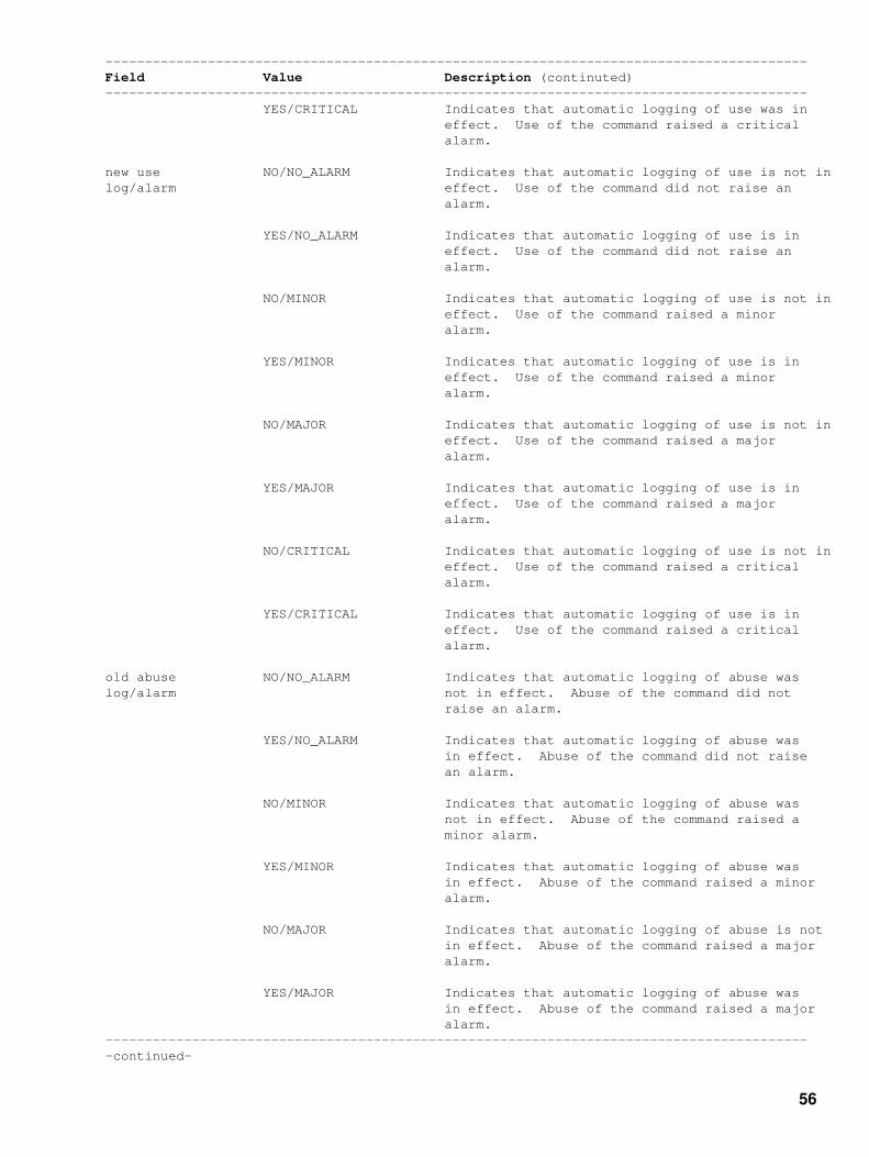
−−−−−−−−−−−−−−−−−−−−−−−−−−−−−−−−−−−−−−−−−−−−−−−−−−−−−−−−−−−−−−−−−−−−−−−−−−−−−−−−−−−−−−−−−Field Value Description (continuted)−−−−−−−−−−−−−−−−−−−−−−−−−−−−−−−−−−−−−−−−−−−−−−−−−−−−−−−−−−−−−−−−−−−−−−−−−−−−−−−−−−−−−−−−− YES/CRITICAL Indicates that automatic logging of use was in effect. Use of the command raised a critical alarm.
new use NO/NO_ALARM Indicates that automatic logging of use is not inlog/alarm effect. Use of the command did not raise an alarm.
YES/NO_ALARM Indicates that automatic logging of use is in effect. Use of the command did not raise an alarm.
NO/MINOR Indicates that automatic logging of use is not in effect. Use of the command raised a minor alarm.
YES/MINOR Indicates that automatic logging of use is in effect. Use of the command raised a minor alarm.
NO/MAJOR Indicates that automatic logging of use is not in effect. Use of the command raised a major alarm.
YES/MAJOR Indicates that automatic logging of use is in effect. Use of the command raised a major alarm.
NO/CRITICAL Indicates that automatic logging of use is not in effect. Use of the command raised a critical alarm.
YES/CRITICAL Indicates that automatic logging of use is in effect. Use of the command raised a critical alarm.
old abuse NO/NO_ALARM Indicates that automatic logging of abuse waslog/alarm not in effect. Abuse of the command did not raise an alarm.
YES/NO_ALARM Indicates that automatic logging of abuse was in effect. Abuse of the command did not raise an alarm.
NO/MINOR Indicates that automatic logging of abuse was not in effect. Abuse of the command raised a minor alarm.
YES/MINOR Indicates that automatic logging of abuse was in effect. Abuse of the command raised a minor alarm.
NO/MAJOR Indicates that automatic logging of abuse is not in effect. Abuse of the command raised a major alarm.
YES/MAJOR Indicates that automatic logging of abuse was in effect. Abuse of the command raised a major alarm.−−−−−−−−−−−−−−−−−−−−−−−−−−−−−−−−−−−−−−−−−−−−−−−−−−−−−−−−−−−−−−−−−−−−−−−−−−−−−−−−−−−−−−−−−−continued−
56

−−−−−−−−−−−−−−−−−−−−−−−−−−−−−−−−−−−−−−−−−−−−−−−−−−−−−−−−−−−−−−−−−−−−−−−−−−−−−−−−−−−−−−−−−Field Value Description (continuted)−−−−−−−−−−−−−−−−−−−−−−−−−−−−−−−−−−−−−−−−−−−−−−−−−−−−−−−−−−−−−−−−−−−−−−−−−−−−−−−−−−−−−−−−− NO/CRITICAL Indicates that automatic logging of abuse was not in effect. Abuse of the command raised a critical alarm.
YES/CRITICAL Indicates that automatic logging of abuse was in effect. Abuse of the command raised a critical alarm.
new abuse NO/NO_ALARM Indicates that automatic logging of abuse is not log/alarm in effect. Abuse of the command did not raise an alarm.
YES/NO_ALARM Indicates that automatic logging of abuse is in effect. Abuse of the command did not raise an alarm.
NO/MINOR Indicates that automatic logging of abuse is not in effect. Abuse of the command raised a minor alarm.
YES/MINOR Indicates that automatic logging of abuse is in effect. Abuse of the command raised a minor alarm.
NO/MAJOR Indicates that automatic logging of abuse is not in effect. Abuse of the command raised a major alarm.
YES/MAJOR Indicates that automatic logging of abuse is in effect. Abuse of the command raised a major alarm.
NO/CRITICAL Indicates that automatic logging of abuse is not in effect. Abuse of the command raised a critical alarm.
YES/CRITICAL Indicates that automatic logging of abuse is in effect. Abuse of the command raised a critical alarm.−−−−−−−−−−−−−−−−−−−−−−−−−−−−−−−−−−−−−−−−−−−−−−−−−−−−−−−−−−−−−−−−−−−−−−−−−−−−−−−−−−−−−−−−−−End−
57

Nortel DMS−100 Security Log ReportsSECU105
Explanation
The Security (SECU) subsystem generates SECU105 when one user changes the password foranother user.
Format
The log report format for SECU105 is as follows:
SECU105 mmmdd hh:mm:ss ssdd INFO User: <user> on <term>. Password has been changed for <usernm>.
Example
An example of log report SECU105 follows:
SECU105 APR01 12:00:00 2112 INFO User: JANET on MAP. Password has been changed for OPERATOR.
Field Descriptions
The following table describes each field in the log report:
−−−−−−−−−−−−−−−−−−−−−−−−−−−−−−−−−−−−−−−−−−−−−−−−−−−−−−−−−−−−−−−−−−−−−−−−−−−−−−−−−−−−−−−−−Field Value Description−−−−−−−−−−−−−−−−−−−−−−−−−−−−−−−−−−−−−−−−−−−−−−−−−−−−−−−−−−−−−−−−−−−−−−−−−−−−−−−−−−−−−−−−−INFO constant Indicates information about the SECU subsystem.
<user> descriptive text Identifies the user that changes the password. Use the CI command SHOWUSERS for a list of users defined to the system.
on symbolic text Identifies the terminal where the user changed the password. List TERMDEV from CI MAP level for list of terminals.
Password has been symbolic text Identifies the user that had passwordchanged for changed. Use the CI command SHOWUSERS for a list of users defined to the system.−−−−−−−−−−−−−−−−−−−−−−−−−−−−−−−−−−−−−−−−−−−−−−−−−−−−−−−−−−−−−−−−−−−−−−−−−−−−−−−−−−−−−−−−−−End−
58

Nortel DMS−100 Security Log ReportsSECU106
Explanation
The Security (SECU) subsystem generates SECI106 when a user with the proper command classset issues a command. The command is entered in Customer Data table CMDS. The systemexecutes the command.
Format
The log report format for SECU106 is as follows:
SECU106 mmmdd hh:mm:ss ssdd INFO User: <user> on <term>. Valid use of command <cmdnm>.
Example
An example of log report SECU106 follows:
SECU106 APR01 12:00:00 2112 INFO User: JANET on MAP. Valid use of command RESTART.
Field Descriptions
The following table describes each field in the log report:
−−−−−−−−−−−−−−−−−−−−−−−−−−−−−−−−−−−−−−−−−−−−−−−−−−−−−−−−−−−−−−−−−−−−−−−−−−−−−−−−−−−−−−−−−Field Value Description−−−−−−−−−−−−−−−−−−−−−−−−−−−−−−−−−−−−−−−−−−−−−−−−−−−−−−−−−−−−−−−−−−−−−−−−−−−−−−−−−−−−−−−−−INFO constant Indicates information about the SECU subsystem.
<user> descriptive text Identifies the user that issues the command. Use the CI command SHOWUSERS for a list of users defined to the system.
on symbolic text Identifies the terminal where the user issued the command. List TERMDEV from CI MAP level for list of terminals.
Valid use of symbolic text Identifies the command that a user with the correctcommand commandset issues. List CMDS from CI MAP level for privileged commands.−−−−−−−−−−−−−−−−−−−−−−−−−−−−−−−−−−−−−−−−−−−−−−−−−−−−−−−−−−−−−−−−−−−−−−−−−−−−−−−−−−−−−−−−−−End−
59

Nortel DMS−100 Security Log ReportsSECU107
Explanation
The Security (SECU) subsystem generates SECU107 when a user without the correct commandclass set issues a command. The command is entered in Customer Data table CMDS. The systemdoes not execute the command.
Format
The log report format for SECU107 is as follows:
SECU107 mmmdd hh:mm:ss ssdd INFO User: <user> on <term>. *UNABLE* to use command: cmdnm. User's effective commandset: n,n,n,n. Command's commandset: n,n,n,n.
Example
An example of log report SECU107 follows:
SECU107 APR01 12:00:00 2112 INFO User: JANET on MAP. *UNABLE* to use command: RESTART. User's effective commandset: 3,2,3,4. Command's commandset: 3,2,3,4,8.
Field Descriptions
The following table describes each field in the log report:
−−−−−−−−−−−−−−−−−−−−−−−−−−−−−−−−−−−−−−−−−−−−−−−−−−−−−−−−−−−−−−−−−−−−−−−−−−−−−−−−−−−−−−−−−Field Value Description−−−−−−−−−−−−−−−−−−−−−−−−−−−−−−−−−−−−−−−−−−−−−−−−−−−−−−−−−−−−−−−−−−−−−−−−−−−−−−−−−−−−−−−−−INFO constant Indicates information about the SECU subsystem.
<user> descriptive text Identifies the invalid user that issues the command. Use the CI command SHOWUSERS for a list of users defined to the system.
on symbolic text Identifies the terminal where the invalid user issued the command. List TERMDEV from CI MAP level for list of terminals.
*UNABLE* to use symbolic text Identifies the privileged command issued by thecommand invalid user. List CMDS from CI MAP level for privileged commands.
User's effective 0−30 Provides the command class set for the usercommandset that issues the command.−−−−−−−−−−−−−−−−−−−−−−−−−−−−−−−−−−−−−−−−−−−−−−−−−−−−−−−−−−−−−−−−−−−−−−−−−−−−−−−−−−−−−−−−−−continued−
60

−−−−−−−−−−−−−−−−−−−−−−−−−−−−−−−−−−−−−−−−−−−−−−−−−−−−−−−−−−−−−−−−−−−−−−−−−−−−−−−−−−−−−−−−−Field Value Description (continuted)−−−−−−−−−−−−−−−−−−−−−−−−−−−−−−−−−−−−−−−−−−−−−−−−−−−−−−−−−−−−−−−−−−−−−−−−−−−−−−−−−−−−−−−−− ALL Indicates the user is authorized to execute all commands.
NONE Indicates the user does not have a command class set.
Command's 0−30 Provides command class set for the command.commandset
ALL Indicates the system requires all command classes to execute the command.
NONE Indicates the system does not require command classes to execute the command.−−−−−−−−−−−−−−−−−−−−−−−−−−−−−−−−−−−−−−−−−−−−−−−−−−−−−−−−−−−−−−−−−−−−−−−−−−−−−−−−−−−−−−−−−−End−
61

Nortel DMS−100 Security Log ReportsSECU108
Explanation
The Security (SECU) subsystem generates SECU108. The subsystem generates SECU108 whena user without the correct command class set attempts to access a table. The user does not accessthe table.
Format
The log report format for SECU108 is as follows:
SECU108 mmmdd hh:mm:ss ssdd INFO User: <user> on <term>. *UNABLE* to access table: <tbl>. User's effective commandset: n,n,n,n. table's commandset: n.
Example
An example of log report SECU108 follows:
SECU108 APR01 12:00:00 2112 INFO User: JANET on MAP. *UNABLE* to access table: TERMDEV. User's effective commandset: 3,2,3,4. table's commandset: 8.
Field Descriptions
The following table describes each field in the log report:
−−−−−−−−−−−−−−−−−−−−−−−−−−−−−−−−−−−−−−−−−−−−−−−−−−−−−−−−−−−−−−−−−−−−−−−−−−−−−−−−−−−−−−−−−Field Value Description−−−−−−−−−−−−−−−−−−−−−−−−−−−−−−−−−−−−−−−−−−−−−−−−−−−−−−−−−−−−−−−−−−−−−−−−−−−−−−−−−−−−−−−−−INFO constant Indicates information about the SECU subsystem.
<user> descriptive text Identifies the invalid user that attempts to access the table. Use CI command SHOWUSERS for a list of users defined to the system.
on symbolic text Identifies the terminal where an invalid user attempted to access a table. List TERMDEV from CI MAP level for list of terminals.
*UNABLE* to access symbolic text Identifies Customer Data table the usertable attempted to access. Refer to Customer Data
Schema, 297−1001−451, for index to CustomerData tables.
User's commandset 0−30 Provides command class set for the user that attempts to access the table.−−−−−−−−−−−−−−−−−−−−−−−−−−−−−−−−−−−−−−−−−−−−−−−−−−−−−−−−−−−−−−−−−−−−−−−−−−−−−−−−−−−−−−−−−−continued−
62

−−−−−−−−−−−−−−−−−−−−−−−−−−−−−−−−−−−−−−−−−−−−−−−−−−−−−−−−−−−−−−−−−−−−−−−−−−−−−−−−−−−−−−−−−Field Value Description (continued)−−−−−−−−−−−−−−−−−−−−−−−−−−−−−−−−−−−−−−−−−−−−−−−−−−−−−−−−−−−−−−−−−−−−−−−−−−−−−−−−−−−−−−−−− NONE Indicates the user does not have a command class set.
ALL Indicates the user is authorized to access all tables.
table's commandset 0−30 Provides the command class set required to access the table.
NONE Indicates the user does not require command classes to access the table.
ALL Indicates a user with a full−privilege command class set can access the table.−−−−−−−−−−−−−−−−−−−−−−−−−−−−−−−−−−−−−−−−−−−−−−−−−−−−−−−−−−−−−−−−−−−−−−−−−−−−−−−−−−−−−−−−−−End−
63

Nortel DMS−100 Security Log ReportsSECU109
Explanation
The Security (SECU) subsystem generates SECU109 when a valid user logs on a terminal usingPriority Login (PLOGIN) procedures.
Format
The log report format for SECU109 is as follows:
SECU109 mmmdd hh:mm:ss ssdd INFO User: <user> PLOGINing on <term>.
Example
An example of log report SECU109 follows:
SECU109 APR01 12:00:00 2112 INFO User: JANET PLOGINing on MAP.
Field Descriptions
The following table describes each field in the log report:
−−−−−−−−−−−−−−−−−−−−−−−−−−−−−−−−−−−−−−−−−−−−−−−−−−−−−−−−−−−−−−−−−−−−−−−−−−−−−−−−−−−−−−−−−Field Value Description−−−−−−−−−−−−−−−−−−−−−−−−−−−−−−−−−−−−−−−−−−−−−−−−−−−−−−−−−−−−−−−−−−−−−−−−−−−−−−−−−−−−−−−−−INFO constant Indicates information about the SECU subsystem.
<user> descriptive text Identifies the user that logged on the terminal with PLOGIN procedures. Use CI command SHOWUSERS for a list of users defined to the system.
PLOGINing on symbolic text Identifies the terminal user logged on with PLOGIN procedures. List TERMDEV from CI MAP level for list of terminals.−−−−−−−−−−−−−−−−−−−−−−−−−−−−−−−−−−−−−−−−−−−−−−−−−−−−−−−−−−−−−−−−−−−−−−−−−−−−−−−−−−−−−−−−−−End−
64
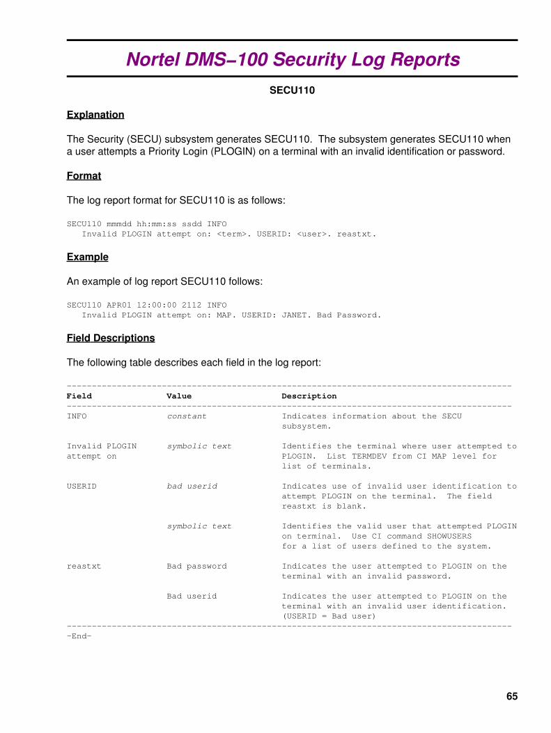
Nortel DMS−100 Security Log ReportsSECU110
Explanation
The Security (SECU) subsystem generates SECU110. The subsystem generates SECU110 whena user attempts a Priority Login (PLOGIN) on a terminal with an invalid identification or password.
Format
The log report format for SECU110 is as follows:
SECU110 mmmdd hh:mm:ss ssdd INFO Invalid PLOGIN attempt on: <term>. USERID: <user>. reastxt.
Example
An example of log report SECU110 follows:
SECU110 APR01 12:00:00 2112 INFO Invalid PLOGIN attempt on: MAP. USERID: JANET. Bad Password.
Field Descriptions
The following table describes each field in the log report:
−−−−−−−−−−−−−−−−−−−−−−−−−−−−−−−−−−−−−−−−−−−−−−−−−−−−−−−−−−−−−−−−−−−−−−−−−−−−−−−−−−−−−−−−−Field Value Description−−−−−−−−−−−−−−−−−−−−−−−−−−−−−−−−−−−−−−−−−−−−−−−−−−−−−−−−−−−−−−−−−−−−−−−−−−−−−−−−−−−−−−−−−INFO constant Indicates information about the SECU subsystem.
Invalid PLOGIN symbolic text Identifies the terminal where user attempted to attempt on PLOGIN. List TERMDEV from CI MAP level for list of terminals.
USERID bad userid Indicates use of invalid user identification to attempt PLOGIN on the terminal. The field reastxt is blank.
symbolic text Identifies the valid user that attempted PLOGIN on terminal. Use CI command SHOWUSERS for a list of users defined to the system.
reastxt Bad password Indicates the user attempted to PLOGIN on the terminal with an invalid password.
Bad userid Indicates the user attempted to PLOGIN on the terminal with an invalid user identification. (USERID = Bad user)−−−−−−−−−−−−−−−−−−−−−−−−−−−−−−−−−−−−−−−−−−−−−−−−−−−−−−−−−−−−−−−−−−−−−−−−−−−−−−−−−−−−−−−−−−End−
65

Nortel DMS−100 Security Log ReportsSECU111
Explanation
The Security (SECU) subsystem generates SECU111 when a user changes the command class setfor a terminal. Customer Data table TERMDEV defines the command class set for a terminal.
Format
The log report format for SECU111 is as follows:
SECU111 mmmdd hh:mm:ss ssdd INFO User: <user> on <term>. TERMDEV COMCLASS changed for <term>. Old commandset: n,n,n,n,n. New commandset: n.
Example
An example of log report SECU111 follows:
SECU111 APR01 12:00:00 2112 INFO User: JANET on MAP. TERMDEV COMCLASS changed for MAP1. Old commandset: 3,4,5,6. New commandset: 8.
Field Descriptions
The following table describes each field in the log report:
−−−−−−−−−−−−−−−−−−−−−−−−−−−−−−−−−−−−−−−−−−−−−−−−−−−−−−−−−−−−−−−−−−−−−−−−−−−−−−−−−−−−−−−−−Field Value Description−−−−−−−−−−−−−−−−−−−−−−−−−−−−−−−−−−−−−−−−−−−−−−−−−−−−−−−−−−−−−−−−−−−−−−−−−−−−−−−−−−−−−−−−−INFO constant Indicates information about the SECU subsystem.
<user> descriptive text Identifies the user that changed the command set for a terminal that TERMDEV defines. Use CI command SHOWUSERS for a list of users defined to the system.
on symbolic text Identifies the terminal where the user changed another terminal commandset. List TERMDEV from CI MAP level for list of terminals.
TERMDEV COMCLASS symbolic text Identifies the terminal that the userchanged for changed the command set in TERMDEV. List TERMDEV from CI MAP level for list of terminals.
Old commandset 0−30 Identifies the command class set the user earlier assigned to terminal.−−−−−−−−−−−−−−−−−−−−−−−−−−−−−−−−−−−−−−−−−−−−−−−−−−−−−−−−−−−−−−−−−−−−−−−−−−−−−−−−−−−−−−−−−−continued−
66

−−−−−−−−−−−−−−−−−−−−−−−−−−−−−−−−−−−−−−−−−−−−−−−−−−−−−−−−−−−−−−−−−−−−−−−−−−−−−−−−−−−−−−−−−Field Value Description (continued)−−−−−−−−−−−−−−−−−−−−−−−−−−−−−−−−−−−−−−−−−−−−−−−−−−−−−−−−−−−−−−−−−−−−−−−−−−−−−−−−−−−−−−−−− ALL Indicates the user assigned all command classes to the terminal.
NONE Indicates the user did not assign command classes to the terminal.
New commandset 0−30 Identifies the command class set now assigned to the terminal.
ALL Indicates the user assigned all command classes to the terminal.
NONE Indicates the user did not assign command classes to the terminal.−−−−−−−−−−−−−−−−−−−−−−−−−−−−−−−−−−−−−−−−−−−−−−−−−−−−−−−−−−−−−−−−−−−−−−−−−−−−−−−−−−−−−−−−−−End−
67

Nortel DMS−100 Security Log ReportsSECU112
Explanation
The Security (SECU) subsystem generates SECU112 when one user adds or changes the securityprofile for another user.
Format
The log report format for SECU112 is as follows:
SECU112 mmmdd hh:mm:ss ssdd INFO User: <user> on <term>. <type> user <usernm>. Old Stack nnnn Old Priority nnnn Old Language <lang> Old Commandset n,n,n,n. New Stack nnnn New Priority nnnn New Language <lang> New Commandset n,n,n,n.
Example
An example of log report SECU112 follows:
SECU112 APR01 12:00:00 2112 INFO User: JANET on MAP. CHANGE user LISA Old Stack 4000 Old Priority 3 Old Language English Old Commandset 1,2,3,4. New Stack 5000 New Priority 4 New Language Spanish New Commandset 1,2,3,4.
Field Descriptions
The following table describes each field in the log report:
−−−−−−−−−−−−−−−−−−−−−−−−−−−−−−−−−−−−−−−−−−−−−−−−−−−−−−−−−−−−−−−−−−−−−−−−−−−−−−−−−−−−−−−−−Field Value Description−−−−−−−−−−−−−−−−−−−−−−−−−−−−−−−−−−−−−−−−−−−−−−−−−−−−−−−−−−−−−−−−−−−−−−−−−−−−−−−−−−−−−−−−−INFO constant Indicates information about the SECU subsystem.
<user> descriptive text Identifies the user that adds or changes the security profile of another user. Use CI command SHOWUSERS for a list of users defined to the system.−−−−−−−−−−−−−−−−−−−−−−−−−−−−−−−−−−−−−−−−−−−−−−−−−−−−−−−−−−−−−−−−−−−−−−−−−−−−−−−−−−−−−−−−−−continued−
68

−−−−−−−−−−−−−−−−−−−−−−−−−−−−−−−−−−−−−−−−−−−−−−−−−−−−−−−−−−−−−−−−−−−−−−−−−−−−−−−−−−−−−−−−−Field Value Description (continued)−−−−−−−−−−−−−−−−−−−−−−−−−−−−−−−−−−−−−−−−−−−−−−−−−−−−−−−−−−−−−−−−−−−−−−−−−−−−−−−−−−−−−−−−−<term> symbolic text Identifies the terminal where the user added or changed the security profile of another user. List TERMDEV from CI MAP level for list of terminals.
<type> ADD Indicates addition of a new user.
CHANGED Indicates the current user has had attributes changed.
<usernm> 0000−FFFF Identifies the user with the changed security profile. Use CI command SHOWUSERS for a list of users defined to the system.
Old Stack 1500−8000 Identifies number of words for old user process. This field appears when <type> = CHANGED.
Old Priority 1−4 Identifies priority of old user process. This field appears when <type> = CHANGED.
Old Language English, French, Identifies the user interface language for user. German, Spanish, Turkish
Old Commandset 0−30 Identifies command class set earlier assigned to user. This field displayed when <type> = CHANGED.
ALL Indicates that the user assigned the other user to all command classes. This field appears when <type> = CHANGED.
NONE Indicates that the user did not assign the other user to any command classes. This field appears when <type> = CHANGED.
New Stack 1500−8000 Identifies the number of words for the new user process.
New Priority 1−4 Identifies priority of new user process.
New Language English, French, Identifies user interface language for user. German, Spanish, Turkish
New Commandset 0−30 Identifies command class set assigned to user.
ALL Indicates the user assigned the other user to all command classes.
NONE Indicates the user did not assign the other user to any command classes.−−−−−−−−−−−−−−−−−−−−−−−−−−−−−−−−−−−−−−−−−−−−−−−−−−−−−−−−−−−−−−−−−−−−−−−−−−−−−−−−−−−−−−−−−−End−
69

Nortel DMS−100 Security Log ReportsSECU113
Explanation
The Security (SECU) subsystem generates SECU113. The system generates SECU113 when auser makes an attempt to login on a terminal that is not enabled.
Format
The log report format for SECU113 is as follows:
SECU113 mmmdd hh:mm:ss ssdd INFO Attempt to login on disabled console: <term>.
Example
An example of log report SECU113 follows:
SECU113 APR01 12:00:00 2112 INFO Attempt to LOGIN on disabled console: DIALUP.
Field Descriptions
The following table describes each field in the log report:
−−−−−−−−−−−−−−−−−−−−−−−−−−−−−−−−−−−−−−−−−−−−−−−−−−−−−−−−−−−−−−−−−−−−−−−−−−−−−−−−−−−−−−−−−Field Value Description−−−−−−−−−−−−−−−−−−−−−−−−−−−−−−−−−−−−−−−−−−−−−−−−−−−−−−−−−−−−−−−−−−−−−−−−−−−−−−−−−−−−−−−−−INFO constant Indicates information about the SECU subsystem.
Attempt to LOGIN symbolic text Identifies the terminal where the useron disabled console made the attempt to login. List TERMDEV from CI MAP level for list of terminals.−−−−−−−−−−−−−−−−−−−−−−−−−−−−−−−−−−−−−−−−−−−−−−−−−−−−−−−−−−−−−−−−−−−−−−−−−−−−−−−−−−−−−−−−−−End−
70

Nortel DMS−100 Security Log ReportsSECU114
Explanation
The Security (SECU) subsystem generates SECU114 when a console is manually enabled ordisabled.
Format
The log report format for SECU114 is as follows:
SECU114 mmmdd hh:mm:ss ssdd INFO User: <user> on <term>. Manually <able>: <term>.
Example
An example of log report SECU114 follows:
SECU114 APR01 12:00:00 2112 INFO User: JANET on MAP. Manually ENABLE: DIALUP.
Field Descriptions
The following table describes each field in the log report:
−−−−−−−−−−−−−−−−−−−−−−−−−−−−−−−−−−−−−−−−−−−−−−−−−−−−−−−−−−−−−−−−−−−−−−−−−−−−−−−−−−−−−−−−−Field Value Description−−−−−−−−−−−−−−−−−−−−−−−−−−−−−−−−−−−−−−−−−−−−−−−−−−−−−−−−−−−−−−−−−−−−−−−−−−−−−−−−−−−−−−−−−INFO constant Indicates information about the SECU subsystem.
<user> descriptive text Identifies the user that enabled or disabled the terminal. Use CI command SHOWUSERS for a list of users defined to the system.
on symbolic text Identifies the terminal that the user used to enable or disable another terminal. List TERMDEV from CI MAP level for list of terminals. Refer to Customer Data table TERMDEV.
Manually DISABLE Indicates the user manually disabled the terminal.
ENABLE Indicates the user manually enabled the terminal.
<term> symbolic text Identifies the user manually enabled or disabled the terminal. List TERMDEV from CI MAP level for list of terminals.−−−−−−−−−−−−−−−−−−−−−−−−−−−−−−−−−−−−−−−−−−−−−−−−−−−−−−−−−−−−−−−−−−−−−−−−−−−−−−−−−−−−−−−−−−End−
71

Nortel DMS−100 Security Log ReportsSECU115
Explanation
The Security (SECU) subsystem generates SECU115. The subsystem generates SECU115 whenthe user exceeds the maximum login time that LOGINCONTROL command specifies. The systemdisables the terminal.
Format
The log report format for SECU115 is as follows:
SECU115 mmmdd hh:mm:ss ssdd INFO User took too long to LOGIN on: <term>. opttxt.
Example
An example of log report SECU115 follows:
SECU115 APR01 12:00:00 2112 INFO User took too long to LOGIN on: DIALUP. Console was disabled.
Field Descriptions
The following table describes each field in the log report:
−−−−−−−−−−−−−−−−−−−−−−−−−−−−−−−−−−−−−−−−−−−−−−−−−−−−−−−−−−−−−−−−−−−−−−−−−−−−−−−−−−−−−−−−−Field Value Description−−−−−−−−−−−−−−−−−−−−−−−−−−−−−−−−−−−−−−−−−−−−−−−−−−−−−−−−−−−−−−−−−−−−−−−−−−−−−−−−−−−−−−−−−INFO constant Indicates information about the SECU subsystem.
User took too symbolic text Indicates the user exceeded the maximumlong to LOGIN on login time during login attempt. List TERMDEV from CI MAP level for list of terminals.
opttxt Console was Indicates the system disables the enabled disabled terminal that waits for login.
blank Indicates the the system does not disable the enabled terminal that waits for login.−−−−−−−−−−−−−−−−−−−−−−−−−−−−−−−−−−−−−−−−−−−−−−−−−−−−−−−−−−−−−−−−−−−−−−−−−−−−−−−−−−−−−−−−−−End−
72

Nortel DMS−100 Security Log ReportsSECU116
Explanation
The Security (SECU) subsystem generates SECU116. The system generates SECU116 when theuser exceeds the maximum number of invalid login attempts that the LOGINCONTROL commandspecifies. The system disables the console.
Format
The log report format for SECU116 is as follows:
SECU116 mmmdd hh:mm:ss ssdd INFO Too many invalid LOGINs on: <term>. opttxt.
Example
An example of log report SECU116 follows:
SECU116 APR01 12:00:00 2112 INFO Too many invalid LOGINs on: DIALUP. Console was disabled.
Field Descriptions
The following table describes each field in the log report:
−−−−−−−−−−−−−−−−−−−−−−−−−−−−−−−−−−−−−−−−−−−−−−−−−−−−−−−−−−−−−−−−−−−−−−−−−−−−−−−−−−−−−−−−−Field Value Description−−−−−−−−−−−−−−−−−−−−−−−−−−−−−−−−−−−−−−−−−−−−−−−−−−−−−−−−−−−−−−−−−−−−−−−−−−−−−−−−−−−−−−−−−INFO constant Indicates information about the SECU subsystem.
Too many invalid symbolic text Indicates the user made the maximumLOGINs on number of invalid login attempts. List TERMDEV from CI MAP level for list of terminals.
opttxt Console was Indicates the system disabled the disabled enabled terminal that waits for login.
blank Indicates the system disabled the enabled terminal that waits for login.−−−−−−−−−−−−−−−−−−−−−−−−−−−−−−−−−−−−−−−−−−−−−−−−−−−−−−−−−−−−−−−−−−−−−−−−−−−−−−−−−−−−−−−−−−End−
73

Nortel DMS−100 Security Log ReportsSECU117
Explanation
The Security (SECU) subsystem generates SECU117 when the system enables a terminal as theLOGINCONTROL command specifies.
Format
The log report format for SECU117 is as follows:
SECU117 mmmdd hh:mm:ss ssdd INFO Console: <term> has been automatically enabled. reastxt.
Example
An example of log report SECU117 follows:
SECU117 APR01 12:00:00 2112 INFO Console: DIALUP has been automatically enabled. End of disable time.
Field Descriptions
The following table describes each field in the log report:
−−−−−−−−−−−−−−−−−−−−−−−−−−−−−−−−−−−−−−−−−−−−−−−−−−−−−−−−−−−−−−−−−−−−−−−−−−−−−−−−−−−−−−−−−Field Value Description−−−−−−−−−−−−−−−−−−−−−−−−−−−−−−−−−−−−−−−−−−−−−−−−−−−−−−−−−−−−−−−−−−−−−−−−−−−−−−−−−−−−−−−−−INFO constant Indicates information about the SECU subsystem.
Console: <term> has symbolic text Indicates the system enabled the terminal. Listbeen automatically TERMDEV from CI MAP level for list ofenabled. terminals.
reastxt End of disable time Indicates the system enabled the terminal when disable time was exceeded.
To prevent system Indicates the system enables a terminal to lockout prevent being placed on the lockout list. The disable time specified by the LOGINCONTROL command normally equals the default, FOREVER.−−−−−−−−−−−−−−−−−−−−−−−−−−−−−−−−−−−−−−−−−−−−−−−−−−−−−−−−−−−−−−−−−−−−−−−−−−−−−−−−−−−−−−−−−−End−
74

Nortel DMS−100 Security Log ReportsSECU118
Explanation
The Security (SECU) subsystem generates SECU118 when a user is idle for a long period oftime. The system also generates SECU118 when the system detects an open line condition. Thesystem logs the user off the terminal. The terminal security profile defined in table TERMDEV andtable LOGINCONTROL determines if the system can disconnect the terminal.
Format
The log report format for SECU118 is as follows:
SECU118 mmmdd hh:mm:ss ssdd INFO reastxt: <user> on <term> forced out by system. opttxt.
Example
An example of log report SECU118 follows:
SECU118 APR01 12:00:00 2112 INFO Idle User: JANET on MAP forced out by system. Console was disabled.
Field Descriptions
The following table describes each field in the log report:
−−−−−−−−−−−−−−−−−−−−−−−−−−−−−−−−−−−−−−−−−−−−−−−−−−−−−−−−−−−−−−−−−−−−−−−−−−−−−−−−−−−−−−−−−Field Value Description−−−−−−−−−−−−−−−−−−−−−−−−−−−−−−−−−−−−−−−−−−−−−−−−−−−−−−−−−−−−−−−−−−−−−−−−−−−−−−−−−−−−−−−−−INFO constant Indicates information about the SECU subsystem.
reastxt Idle User Indicates user logs on specified terminal does not press the <Enter> key during the timeout period set for the terminal.
Line open Indicates that the system detects a line open condition.
<user> descriptive text Identifies idle user which the system logs out. Use CI command SHOWUSERS for a list of users defined to the system.
on <term> forced symbolic text Identifies terminal, that the system canout by system disconnected. The system logs an idle user off of that terminal. List TERMDEV from CI MAP level for list of terminals.−−−−−−−−−−−−−−−−−−−−−−−−−−−−−−−−−−−−−−−−−−−−−−−−−−−−−−−−−−−−−−−−−−−−−−−−−−−−−−−−−−−−−−−−−−continued−
75

−−−−−−−−−−−−−−−−−−−−−−−−−−−−−−−−−−−−−−−−−−−−−−−−−−−−−−−−−−−−−−−−−−−−−−−−−−−−−−−−−−−−−−−−−Field Value Description (continued)−−−−−−−−−−−−−−−−−−−−−−−−−−−−−−−−−−−−−−−−−−−−−−−−−−−−−−−−−−−−−−−−−−−−−−−−−−−−−−−−−−−−−−−−−opttxt Console was Indicates system logs idle user off terminal. disabled Indicates system disables specified terminal.
blank Indicates system logs idle user off terminal. Indicates system does not disconnects terminal.−−−−−−−−−−−−−−−−−−−−−−−−−−−−−−−−−−−−−−−−−−−−−−−−−−−−−−−−−−−−−−−−−−−−−−−−−−−−−−−−−−−−−−−−−−End−
76

Nortel DMS−100 Security Log ReportsSECU119
Explanation
The Security (SECU) subsystem generates SECU119 when the system disables a terminal after theuser logs out. The subsystem also generates SECU119 when the terminal is busied out.
Format
The log report format for SECU119 is as follows:
SECU119 mmmdd hh:mm:ss ssdd INFO reastxt. Console: <term> disabled.
Example
An example of log report SECU119 follows:
SECU119 APR01 12:00:00 2112 INFO User logout. Console: DIALUP disabled.
Field Descriptions
The following table describes each field in the log report:
−−−−−−−−−−−−−−−−−−−−−−−−−−−−−−−−−−−−−−−−−−−−−−−−−−−−−−−−−−−−−−−−−−−−−−−−−−−−−−−−−−−−−−−−−Field Value Description−−−−−−−−−−−−−−−−−−−−−−−−−−−−−−−−−−−−−−−−−−−−−−−−−−−−−−−−−−−−−−−−−−−−−−−−−−−−−−−−−−−−−−−−−INFO constant Indicates information about the SECU subsystem.
reastxt Console BSY Indicates console is busied out.
User logout Indicates user logs out of system.
Console: <term> symbolic text Indicates the system automatically disables thedisabled terminal when the user logs out. List TERMDEV from CI MAP level for list of terminals.−−−−−−−−−−−−−−−−−−−−−−−−−−−−−−−−−−−−−−−−−−−−−−−−−−−−−−−−−−−−−−−−−−−−−−−−−−−−−−−−−−−−−−−−−−End−
77
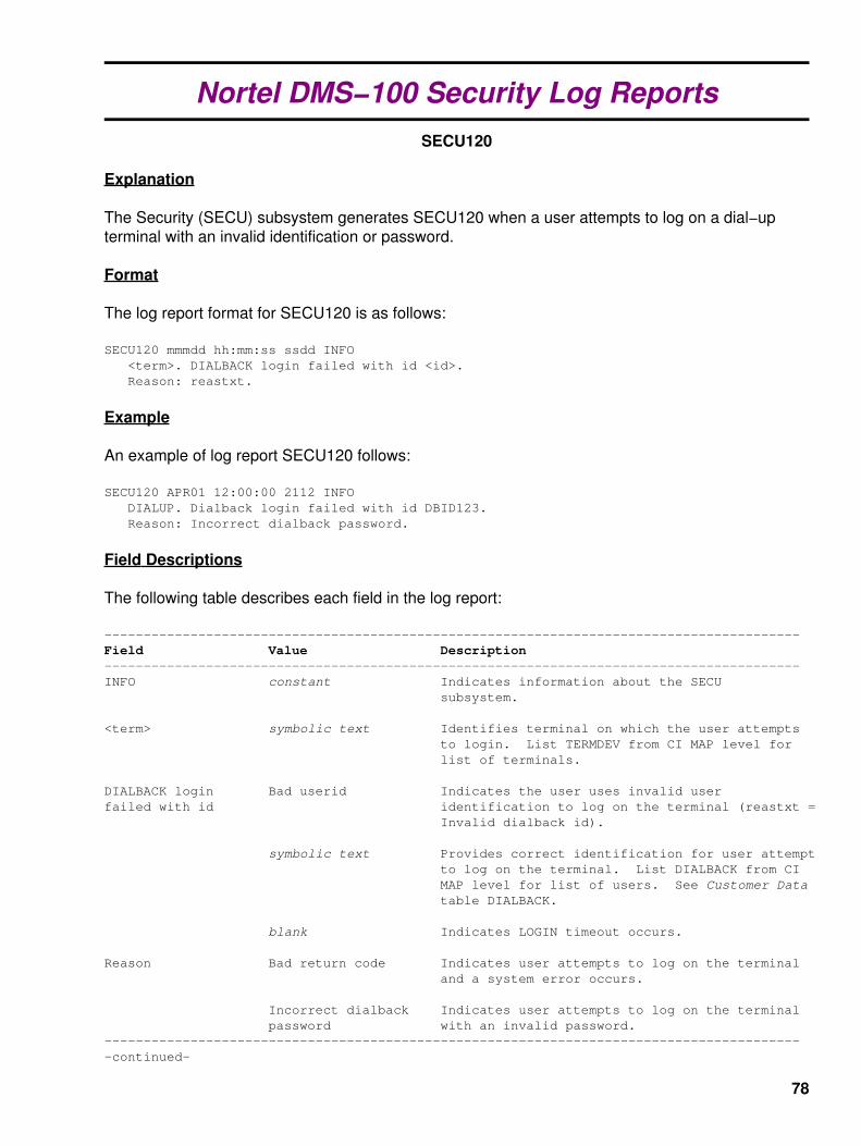
Nortel DMS−100 Security Log ReportsSECU120
Explanation
The Security (SECU) subsystem generates SECU120 when a user attempts to log on a dial−upterminal with an invalid identification or password.
Format
The log report format for SECU120 is as follows:
SECU120 mmmdd hh:mm:ss ssdd INFO <term>. DIALBACK login failed with id <id>. Reason: reastxt.
Example
An example of log report SECU120 follows:
SECU120 APR01 12:00:00 2112 INFO DIALUP. Dialback login failed with id DBID123. Reason: Incorrect dialback password.
Field Descriptions
The following table describes each field in the log report:
−−−−−−−−−−−−−−−−−−−−−−−−−−−−−−−−−−−−−−−−−−−−−−−−−−−−−−−−−−−−−−−−−−−−−−−−−−−−−−−−−−−−−−−−−Field Value Description−−−−−−−−−−−−−−−−−−−−−−−−−−−−−−−−−−−−−−−−−−−−−−−−−−−−−−−−−−−−−−−−−−−−−−−−−−−−−−−−−−−−−−−−−INFO constant Indicates information about the SECU subsystem.
<term> symbolic text Identifies terminal on which the user attempts to login. List TERMDEV from CI MAP level for list of terminals.
DIALBACK login Bad userid Indicates the user uses invalid user failed with id identification to log on the terminal (reastxt = Invalid dialback id).
symbolic text Provides correct identification for user attempt to log on the terminal. List DIALBACK from CI MAP level for list of users. See Customer Data table DIALBACK.
blank Indicates LOGIN timeout occurs.
Reason Bad return code Indicates user attempts to log on the terminal and a system error occurs.
Incorrect dialback Indicates user attempts to log on the terminal password with an invalid password.−−−−−−−−−−−−−−−−−−−−−−−−−−−−−−−−−−−−−−−−−−−−−−−−−−−−−−−−−−−−−−−−−−−−−−−−−−−−−−−−−−−−−−−−−−continued−
78

−−−−−−−−−−−−−−−−−−−−−−−−−−−−−−−−−−−−−−−−−−−−−−−−−−−−−−−−−−−−−−−−−−−−−−−−−−−−−−−−−−−−−−−−−Field Value Description (continued)−−−−−−−−−−−−−−−−−−−−−−−−−−−−−−−−−−−−−−−−−−−−−−−−−−−−−−−−−−−−−−−−−−−−−−−−−−−−−−−−−−−−−−−−− Invalid dialback id Indicates user attempts to log on the terminal with an invalid dialback identifier.
LOGIN timeout Indicates user attempt to log on the terminal, and fails to complete login procedures in the specified time.−−−−−−−−−−−−−−−−−−−−−−−−−−−−−−−−−−−−−−−−−−−−−−−−−−−−−−−−−−−−−−−−−−−−−−−−−−−−−−−−−−−−−−−−−−End−
79

Nortel DMS−100 Security Log ReportsSECU121
Explanation
The Security (SECU) subsystem generates SECU121 when a valid user logs on a dial−upterminal. The user uses normal login procedures to log on the terminal.
Format
The log report format for SECU121 is as follows:
SECU121 mmmdd hh:mm:ss ssdd INFO <term>. Dialback login with id <id>.
Example
An example of log report SECU121 follows:
SECU121 APR01 12:00:00 2112 INFO DIALUP. Dialback login with id DNID123.
Field Descriptions
The following table describes each field in the log report:
−−−−−−−−−−−−−−−−−−−−−−−−−−−−−−−−−−−−−−−−−−−−−−−−−−−−−−−−−−−−−−−−−−−−−−−−−−−−−−−−−−−−−−−−−Field Value Description−−−−−−−−−−−−−−−−−−−−−−−−−−−−−−−−−−−−−−−−−−−−−−−−−−−−−−−−−−−−−−−−−−−−−−−−−−−−−−−−−−−−−−−−−INFO constant Indicates information about the SECU subsystem.
<term> symbolic text Identifies terminal the user logs on. List TERMDEV from CI MAP level for list of terminals.
Dialback login symbolic text Identifies user that logs on specified terminal.with id List DIALBACK from CI MAP level for list of users. See Customer Data table DIALBACK.−−−−−−−−−−−−−−−−−−−−−−−−−−−−−−−−−−−−−−−−−−−−−−−−−−−−−−−−−−−−−−−−−−−−−−−−−−−−−−−−−−−−−−−−−−End−
80
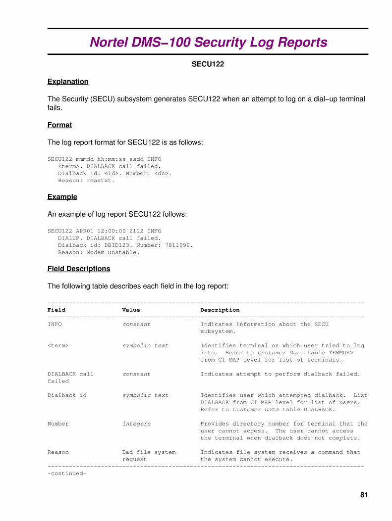
Nortel DMS−100 Security Log ReportsSECU122
Explanation
The Security (SECU) subsystem generates SECU122 when an attempt to log on a dial−up terminalfails.
Format
The log report format for SECU122 is as follows:
SECU122 mmmdd hh:mm:ss ssdd INFO <term>. DIALBACK call failed. Dialback id: <id>. Number: <dn>. Reason: reastxt.
Example
An example of log report SECU122 follows:
SECU122 APR01 12:00:00 2112 INFO DIALUP. DIALBACK call failed. Dialback id: DBID123. Number: 7811999. Reason: Modem unstable.
Field Descriptions
The following table describes each field in the log report:
−−−−−−−−−−−−−−−−−−−−−−−−−−−−−−−−−−−−−−−−−−−−−−−−−−−−−−−−−−−−−−−−−−−−−−−−−−−−−−−−−−−−−−−−−Field Value Description−−−−−−−−−−−−−−−−−−−−−−−−−−−−−−−−−−−−−−−−−−−−−−−−−−−−−−−−−−−−−−−−−−−−−−−−−−−−−−−−−−−−−−−−−INFO constant Indicates information about the SECU subsystem.
<term> symbolic text Identifies terminal on which user tried to log into. Refer to Customer Data table TERMDEV from CI MAP level for list of terminals.
DIALBACK call constant Indicates attempt to perform dialback failed.failed
Dialback id symbolic text Identifies user which attempted dialback. List DIALBACK from CI MAP level for list of users. Refer to Customer Data table DIALBACK.
Number integers Provides directory number for terminal that the user cannot access. The user cannot access the terminal when dialback does not complete.
Reason Bad file system Indicates file system receives a command that request the system cannot execute.−−−−−−−−−−−−−−−−−−−−−−−−−−−−−−−−−−−−−−−−−−−−−−−−−−−−−−−−−−−−−−−−−−−−−−−−−−−−−−−−−−−−−−−−−−continued−
81

−−−−−−−−−−−−−−−−−−−−−−−−−−−−−−−−−−−−−−−−−−−−−−−−−−−−−−−−−−−−−−−−−−−−−−−−−−−−−−−−−−−−−−−−−Field Value Description (continued)−−−−−−−−−−−−−−−−−−−−−−−−−−−−−−−−−−−−−−−−−−−−−−−−−−−−−−−−−−−−−−−−−−−−−−−−−−−−−−−−−−−−−−−−− Bad return code Indicates system received an error code that the system cannot understand.
Call aborted by Indicates system aborts the dialback call. For system example, the modem equipment is not available for use.
Call connected Indicates modem dials out.
Could not initiate Indicates system cannot complete login login sequence. For example, the file system fails to output data through the modem.
Error in file system Indicates error occurs in file system. For example, a corrupted file reference number.
Invalid directory Indicates dialback directory number that is not number correct.
Line was busy Indicates modem discovers the line was busy when the modem makes the dialback call.
Modem unstable Indicates modem does not work correctly.
No answer Indicates modem is not available, or the called party can not answer when the modem placed the dialback call.
No modem available Indicates modem is not available to make for dialback dialback call.
Unable to detect Indicates modem is not able to detect carrier. carrier
Unable to detect Indicates modem is not able to detect dial tone. dialtone−−−−−−−−−−−−−−−−−−−−−−−−−−−−−−−−−−−−−−−−−−−−−−−−−−−−−−−−−−−−−−−−−−−−−−−−−−−−−−−−−−−−−−−−−−End−
82

Nortel DMS−100 Security Log ReportsSECU123
Explanation
The Security (SECU) subsystem generates SECU123. The subsystem generates SECU123 whenattempts to log on a dial−up terminal succeed, dialback call is successful, and login is complete.
Format
The log report format for SECU123 is as follows:
SECU123 mmmdd hh:mm:ss ssdd INFO <term>. DIALBACK call connected. Dialback id: <id>. Number: <dn>. New <term>.
Example
An example of log report SECU123 follows:
SECU123 APR01 12:00:00 2112 INFO DIALUP. DIALBACK call connected. Dialback id: DBID123. Number: 7811999. New DIALUP1.
Field Descriptions
The following table describes each field in the log report:
−−−−−−−−−−−−−−−−−−−−−−−−−−−−−−−−−−−−−−−−−−−−−−−−−−−−−−−−−−−−−−−−−−−−−−−−−−−−−−−−−−−−−−−−−Field Value Description−−−−−−−−−−−−−−−−−−−−−−−−−−−−−−−−−−−−−−−−−−−−−−−−−−−−−−−−−−−−−−−−−−−−−−−−−−−−−−−−−−−−−−−−−INFO constant Indicates information about the SECU subsystem.
<term> symbolic text Identifies first terminal where user attempts to logon. See Customer Data table TERMDEV from CI MAP level for list of terminals.
DIALBACK call constant Indicates attempt to perform dialback isconnected successful.
Dialback id symbolic text Identifies user attempted dialbacks. List DIALBACK from CI MAP level for list of users. See Customer Data table DIALBACK.
Number integers Provides directory number for terminal to complete dialback call.
New symbolic text Identifies terminal used in dialback connection. List table TERMDEV from CI MAP level.−−−−−−−−−−−−−−−−−−−−−−−−−−−−−−−−−−−−−−−−−−−−−−−−−−−−−−−−−−−−−−−−−−−−−−−−−−−−−−−−−−−−−−−−−−End−
83

Nortel DMS−100 Security Log ReportsSECU124
Explanation
The Security (SECU) subsystem generates log report SECU124 when a user changes the dialbackpassword for a user.
Format
The log report format for SECU124 is as follows:
SECU124 mmmdd hh:mm:ss ssdd INFO User: <user> on <term>. DIALBACK password changed for id <id>.
Example
An example of log report SECU124 follows:
SECU124 APR01 12:00:00 2112 INFO User: JANET on DIALUP. DIALBACK password changed for id DBID123.
Field Descriptions
The following table describes each field in the log report:
−−−−−−−−−−−−−−−−−−−−−−−−−−−−−−−−−−−−−−−−−−−−−−−−−−−−−−−−−−−−−−−−−−−−−−−−−−−−−−−−−−−−−−−−−Field Value Description−−−−−−−−−−−−−−−−−−−−−−−−−−−−−−−−−−−−−−−−−−−−−−−−−−−−−−−−−−−−−−−−−−−−−−−−−−−−−−−−−−−−−−−−−INFO constant Indicates information about the SECU subsystem.
<user> descriptive text Identifies user that changes dial−up password. Use CI command SHOWUSERS for a list of users defined to the system.
on symbolic text Identifies terminal where user makes the change to the dial−up password. List
Customer Data table TERMDEV from CI MAP level for list of terminals.
DIALBACK password symbolic text Identifies user for which the userchanged for id changes dialback password. List DIALBACK from CI MAP level for a list of users. See Customer Data table DIALBACK.−−−−−−−−−−−−−−−−−−−−−−−−−−−−−−−−−−−−−−−−−−−−−−−−−−−−−−−−−−−−−−−−−−−−−−−−−−−−−−−−−−−−−−−−−−End−
84

Nortel DMS−100 Security Log ReportsSECU125
Explanation
The Security (SECU) subsystem generates log report SECU125 when a user enables dialback for adial−up terminal.
Format
The log report format for SECU125 is as follows:
SECU125 mmmdd hh:mm:ss ssdd INFO User: <user> on <term>. DIALBACK enabled for <term>.
Example
An example of log report SECU125 follows:
SECU125 APR01 12:00:00 2112 INFO User: JANET on DIALUP. DIALBACK enabled for DBID123.
Field Descriptions
The following table describes each field in the log report:
−−−−−−−−−−−−−−−−−−−−−−−−−−−−−−−−−−−−−−−−−−−−−−−−−−−−−−−−−−−−−−−−−−−−−−−−−−−−−−−−−−−−−−−−−Field Value Description−−−−−−−−−−−−−−−−−−−−−−−−−−−−−−−−−−−−−−−−−−−−−−−−−−−−−−−−−−−−−−−−−−−−−−−−−−−−−−−−−−−−−−−−−INFO constant Indicates information about the SECU subsystem.
<user> descriptive text Identifies user that enables dial−up terminal. Use CI command SHOWUSERS for a list of users defined to the system.
on symbolic text Identifies terminal on which the user enables the dial−up terminal. List Customer Data table TERMDEV from CI MAP level for list of terminals.
DIALBACK enabled symbolic text Identifies dial−up terminal that the user enables.for See Customer Data table TERMDEV. −−−−−−−−−−−−−−−−−−−−−−−−−−−−−−−−−−−−−−−−−−−−−−−−−−−−−−−−−−−−−−−−−−−−−−−−−−−−−−−−−−−−−−−−−−End−
85

Nortel DMS−100 Security Log ReportsSECU126
Explanation
The Security (SECU) subsystem generates log report SECU126 when a user disables dialback for adial−up terminal.
Format
The log report format for SECU126 is as follows:
SECU126 mmmdd hh:mm:ss ssdd INFO User: <user> on <term>. DIALBACK disabled for <term>.
Example
An example of log report SECU126 follows:
SECU126 APR01 12:00:00 2112 INFO User: JANET on DIALUP. DIALBACK disabled for DBID123.
Field Descriptions
The following table describes each field in the log report:
−−−−−−−−−−−−−−−−−−−−−−−−−−−−−−−−−−−−−−−−−−−−−−−−−−−−−−−−−−−−−−−−−−−−−−−−−−−−−−−−−−−−−−−−−Field Value Description−−−−−−−−−−−−−−−−−−−−−−−−−−−−−−−−−−−−−−−−−−−−−−−−−−−−−−−−−−−−−−−−−−−−−−−−−−−−−−−−−−−−−−−−−INFO constant Indicates information about the SECU subsystem.
<user> descriptive text Identifies user that disables the dial−up terminal. Use CI command SHOWUSERS for a list of users defined to the system.
on symbolic text Identifies terminal on which the user disables the dial−up terminal. List Customer Data table TERMDEV from CI MAP level for list of terminals.
DIALBACK disabled symbolic text Identifies dial−up terminal that the user disables.for See Customer Data table TERMDEV. −−−−−−−−−−−−−−−−−−−−−−−−−−−−−−−−−−−−−−−−−−−−−−−−−−−−−−−−−−−−−−−−−−−−−−−−−−−−−−−−−−−−−−−−−−End−
86

Nortel DMS−100 Table DNINVTable Name
Directory Number Inventory.
Functional Description of Table DNINV
Table DNINV is a read−only table. This table replaces table DN. Table DNINV contains data for allassigned Directory Numbers (DN). The data includes DNs from table DNROUTE.
Table DNINV automatically gathers information when the operating company:
Assigns DNs.• Uses DNs from tables other than table DNINV, such as table LENLINES or table IBNLINES.•
There is no input form for this table.
Attention − Operating Company Personnel: Do not change any of the line data tables throughtable control because you may corrupt the internal database. Use the Service Order System(SERVORD) to update subscriber line data.
The following table describes different selectors for table DNINV.
−−−−−−−−−−−−−−−−−−−−−−−−−−−−−−−−−−−−−−−−−−−−−−−−−−−−−−−−−−−−−−−−−−−−−−−−−−−−−−−−−−−−−−−−−DNINV Features
DN Selector Use−−−−−−−−−−−−−−−−−−−−−−−−−−−−−−−−−−−−−−−−−−−−−−−−−−−−−−−−−−−−−−−−−−−−−−−−−−−−−−−−−−−−−−−−−A Integrated Business Network (IBN) data network addressACDTK Automatic Call Distribution (ACD) trunk directory numberC No longer usedD Treatment selectorFEAT Virtual DNH POTS line that is part of a hunt groupHC Hunt group member with call forward optionIHC Hunt group member IBN line with call forward optionILC IBN line with call forward optionIMC IBN Multiple Directory Number (MDN) line with call forward optionL Simple POTS lineM Attendant consoleLC Simple POTS line with call forward optionMDN Multiple Directory Number (MDN)MM Meet−Me conference (datafill table MMCONF)P Multi−party POTS lineSC Series CompletionSCM Series Completion for the primary of an MDN groupSDN Secondary Directory Number−−−−−−−−−−−−−−−−−−−−−−−−−−−−−−−−−−−−−−−−−−−−−−−−−−−−−−−−−−−−−−−−−−−−−−−−−−−−−−−−−−−−−−−−−−End−
87

ISDN Shared DNs
Different Logical Terminal Identifiers (LTID) can share DNs on ISDN Basic Rate Interface (BRI)lines. When this relationship occurs, the DNRESULT field of table DNINV of the shared DN showsone LTID only. The following rules determine the LTID that appears:
The Voice−band Information (VI) can share a DN between either the Circuit−Mode Data (CMD) or Packet−ModeData (PMD) call types. When this relationship occurs, the VI appearance of the LTID shows in field DNRESULT.
•
The CMD can share a DN with the PMD call types. When this relationship occurs, the CMD appearance of theLTID appears in field DNRESULT.
•
All three call types (Call VI, CMD, and PMD) can share a DN. When these relationships occur, only the VIappearance of the LTID displays in field DNRESULT.
•
Datafill Sequence
There is no requirement to datafill other tables before table DNINV.
Table Size
As determined by the ACTIVE_DN_SYSTEM parameter, computation of the store requirementdepends on the use of the DN systems that follow:
North American• Universal• Enhanced North American•
For the North American DN system, table DNINV holds up to 1,000,000 DNs.
For the Universal and Enhanced North American DN systems, when many area code and officecode combinations are datafilled on the switch, table DNINV holds up to 1,000,000 DNs.
The maximum tuple for table DNINV depends on the criteria that follows:
The number of area codes and office codes used.• The number of digits used for the station code.•
North American DN System
The North American DN system is the best system to use when:
A local switch holds all the numbers used in a given office code.• The system uses all thousand groups to near capacity.•
When Local Number Portability (LNP) and multiple service providers use this system, the systemuses a lot of memory.
A TOFCNO (the index for table TOFCNAME or TOFCNAME entry) is a valid area and office codecombination from table TOFCNAME. Calculate the store required for each TOFCNO (in bytes) withthe formula that follows:
(100 + 4,000) * (number of thousand groups)
88

The maximum store requirement for each TOFCNAME is forty 100−bytes. The maximum storerequirement for a thousand group in a TOFCNAME is 4,000−bytes, with a 100−byte overhead forthe TOFCNAME.
The North American DN system is the best when the DN structure is tight because it allocates DNsby blocks of 1,000.
Universal DN System
The Universal DN system uses more store when the system allocates all the possible stationcodes. If DNs move across many area codes and office codes, table DNINV uses more memorystore.
Note: The Enhanced North American DN system is like the Universal DN system, except thatEnhanced North American uses the 3−3−4 format. Only the APC load uses the Enhanced NorthAmerican system.
Calculate the store required (in bytes) for each TOFCNO with the formula that follows:
6 * ([tuple count of DNINV] − [tuple count of DNROUTE]) + 44 * (1 + [number of 1−digitprefixes] + [number of 2−digit prefixes] + [number of 3−digit prefixes] + [number of4−digit prefixes] + [...]) + 6
Note: In this formula, the tuple count of DNINV is the tuple count of DNINV for theTOFCNAME. The tuple count of DNROUTE is the tuple count of DNROUTE for the TOFCNAME.
This formula applies to more than the North American industry (for example, more than a 3−digitprefix or 4−digit station code). Use this formula for station codes of any length.
The maximum store requirement for each TOFCNAME is one hundred eight 890−bytes. Themaximum store requirement for a thousand group in a TOFCNAME is ten 884−bytes. Thisrequirement includes a 50−byte overhead for the TOFCNAME.
Datafill Example for Table DNINV
The following table is an example of datafill for DNINV for the Universal DN system. The exampledatafill is for the TOFCNO 709 333. TOFCNO 709 333 contains all station codes with the 102x,104x format, and a half of the 171x range, These codes are datafilled against lines.
−−−−−−−−−−−−−−−−−−−−−−−−−−−−−−−−−−−−−−−−−−−−−−−−−−−−−−−−−−−−−−−−−−−−−−−−−−−−−−−−−−−−−−−−−Example of a MAP display:
AREACODE OFCCODE STNCODE DNRESULT______________________________________________709 333 1020 L HOST 02 0 05 03709 333 1021 L HOST 02 0 05 04709 333 1022 L HOST 02 0 13 06709 333 1023 L HOST 02 0 13 07 709 333 1024 L REM3 03 0 00 01 709 333 1025 L REM3 03 0 00 10 709 333 1026 L REM3 03 0 01 11 (etc.)709 333 1040 L REM3 03 0 16 15709 333 1041 L REM3 03 0 13 26709 333 1042 L REM3 03 0 13 05 (etc.)______________________________________________
89

In total, the TOFCNO holds 25 DNs (not any of which are in table DNROUTE). The number ofprefixes follows:
The number of 1−digit prefixes (1xxx) is 1.• The number of 2−digit prefixes (10xx, 17xx) is 2.• The number of 3−digit prefixes (102x, 104x, 171x) is 3.•
Calculate the memory impact for the TOFCNAME as follows:
6 * 25 + 44 * (1 + 1 + 2 + 3) + 6 = 464−bytes
In the North American DN system, these DNs exist in the same thousand group (1xxx). Thememory impact for the TOFCNAME is:
(100 + 4,000) * 1 = 4,100−bytes
The following datafill example for table DNINV shows:
DNs with Multiple Appearance Directory Number (MADN) Call Appearance Call Handling (CACH).• The group size.• Call Appearance (CA) fields.• The VI and CMD call types share the VI appearance of a DN.•
−−−−−−−−−−−−−−−−−−−−−−−−−−−−−−−−−−−−−−−−−−−−−−−−−−−−−−−−−−−−−−−−−−−−−−−−−−−−−−−−−−−−−−−−−Example of a MAP display:
AREACODE OFCCODE STNCODE DNRESULT______________________________________________613 621 5962 MDN SCA 2 0 613 621 5963 MDN SCA 3 0 613 621 5964 MDN CACH 55 1 613 621 5965 MDN CACH 10 1 613 621 5966 L EKTS 1 613 621 5966 L EKTS 1 613 621 5966 L EKTS 1 613 621 5966 L EKTS 1613 621 5967 L ISDN 19 (etc.)______________________________________________
90

Nortel DMS−100 Table TOFCNAMETable Name
Terminating Office Name.
Functional Description of Table TOFCNAME
Table TOFCNAME stores the area code and office code for the switch. A Terminating OfficeNumber (TOFCNO) consists of both an area code and an office code. Table HNPACONT or tableSNPANAME must define the area code.
Table TOFCNAME replaces table THOUGRP. Table DNROUTE stores all routing informationoriginally stored in table THOUGRP.
Software Optionality Control (SOC) options NPE00001 and NPE00002 implement duplicate officecode and table TOFCNAME expansion capabilities. When NPE00001 is active, you can datafill oneoffice code against more than one area code in table TOFCNAME. When NPE00002 is active, youcan datafill table TOFCNAME with up to 8,151 entries.
Office parameter ACTIVE_DN_SYSTEM in table OFCENG controls the Directory Number (DN)system in use on the switch. You can set this parameter to the following:
NORTH_AMERICAN − In this occurrence, table TOFCNAME can store up to 100 entries (tuples)•
UNIVERSAL − In this case, the following occurs:•
If the state of SOC option NPE00002 is IDLE, table TOFCNAME can store up to 1,024 entries♦
If the state of SOC option NPE00002 is ON, table TOFCNAME can store up to 8,151 entries♦
Note: Unless SOC option NPE00001 is active, the DMS−100 switch does not allow two area codesto share the same office code.
Note: When the capacity of table TOFCNAME increases, the capacity of tables DNINV andDNROUTE decreases (from 1,000,000 to 300,000).
Local Number Portability
For Local Number Portability (LNP), it is preferable for the switch to use the Universal DN systemwith the North American dialing plan.
The DN is "ported−in" if you move the DN from a donor switch to a recipient switch. OptionNONNATIVE in field OPTIONS is assigned to area code and office code entries for ported−in DNs.
Note: In North American applications, if table HOMELRN uses the resident area code and officecode, you cannot change the resident area code and office code to nonresident.
91

Datafill Sequence
Datafill one or the other of the following tables before table TOFCNAME:
HNPACONT (List of Home NPA Code Subtables Table)• SNPANAME (Serving Numbering Plan Area Name Table)•
Table Size
The size of table TOFCNAME depends on:
The value of office parameter ACTIVE_DN_SYSTEM in table OFCENG.• If SOC option NPE00002 is active.•
The following table shows sizes for table TOFCNAME.
−−−−−−−−−−−−−−−−−−−−−−−−−−−−−−−−−−−−−−−−−−−−−−−−−−−−−−−−−−−−−−−−−−−−−−−−−−−−−−−−−−−−−−−−−TOFCNAME Size
Value of ACTIVE_DN_SYSTEM Maximum size of TOFCNAME−−−−−−−−−−−−−−−−−−−−−−−−−−−−−−−−−−−−−−−−−−−−−−−−−−−−−−−−−−−−−−−−−−−−−−−−−−−−−−−−−−−−−−−−−NORTH_AMERICAN 100 tuples
UNIVERSAL 1,024 tuples if NPE00002 is not active 8,151 tuples if NPE00002 is active−−−−−−−−−−−−−−−−−−−−−−−−−−−−−−−−−−−−−−−−−−−−−−−−−−−−−−−−−−−−−−−−−−−−−−−−−−−−−−−−−−−−−−−−−
Datafill
The following table lists datafill for table TOFCNAME.
−−−−−−−−−−−−−−−−−−−−−−−−−−−−−−−−−−−−−−−−−−−−−−−−−−−−−−−−−−−−−−−−−−−−−−−−−−−−−−−−−−−−−−−−−Field Descriptions for Table TOFCNAME
Field or Subfield Entry Explanation−−−−−−−−−−−−−−−−−−−−−−−−−−−−−−−−−−−−−−−−−−−−−−−−−−−−−−−−−−−−−−−−−−−−−−−−−−−−−−−−−−−−−−−−−AREACODE 0 to 9999999 Area Code Enter the area code. (vector of up to 7 digits) The area code (NPA) identifies a geographical area served by the switch. This field can contain one to seven digits. In an office that uses the North American numbering plan, the area code must be three digits.
Enter an area code defined in table SNPANAME.−−−−−−−−−−−−−−−−−−−−−−−−−−−−−−−−−−−−−−−−−−−−−−−−−−−−−−−−−−−−−−−−−−−−−−−−−−−−−−−−−−−−−−−−−OFCCODE 0 to 9999999 Office Code Enter the office code. (vector of up to 7 digits) or $ The area code region consists of a number of areas. The office code identifies the area served by the office. An office code can have from zero to seven digits. For an office that uses the North American numbering plan, the office code must contain three digits.
Enter a number that is not used as an area code. For example, if the area code is 613, the office code cannot be 613.−−−−−−−−−−−−−−−−−−−−−−−−−−−−−−−−−−−−−−−−−−−−−−−−−−−−−−−−−−−−−−−−−−−−−−−−−−−−−−−−−−−−−−−−−−continued−
92

−−−−−−−−−−−−−−−−−−−−−−−−−−−−−−−−−−−−−−−−−−−−−−−−−−−−−−−−−−−−−−−−−−−−−−−−−−−−−−−−−−−−−−−−−Field or Subfield Entry Explanation (continued)−−−−−−−−−−−−−−−−−−−−−−−−−−−−−−−−−−−−−−−−−−−−−−−−−−−−−−−−−−−−−−−−−−−−−−−−−−−−−−−−−−−−−−−−−
Note: Service interruption can occur if you enter an office code that is an area code. The switch can route calls to the wrong location because the switch cannot determine the termination point of the call.
A tuple (AREACODE plus OFCCODE entry) cannot be an expansion or reduction of another entry. For example, if 200 34 (area code 200 plus office code 34) is a tuple, you cannot add the following tuples to the table: 20 03, 2003 45, or 20 034.−−−−−−−−−−−−−−−−−−−−−−−−−−−−−−−−−−−−−−−−−−−−−−−−−−−−−−−−−−−−−−−−−−−−−−−−−−−−−−−−−−−−−−−−−OPTIONS NONNATIVE Ported−In DN
Enter NONNATIVE to identify a ported−in DN. End the tuple with a $ (dollar sign).
Note: Translations ports in only DNs with nonnative NPA−NXX that reside on the switch.
CODEHLDR Enter CODEHLDR to indicate that an NPA−NXX is LERG assigned even though 1,000 blocks may be pooled out to other switches. To assign the CODEHLDR option to a tuple the NPE00005 SOC option must be active.
Note: The CODEHLDR option cannot be present with the NONNATIVE TOFCNAME option and vice versa.−−−−−−−−−−−−−−−−−−−−−−−−−−−−−−−−−−−−−−−−−−−−−−−−−−−−−−−−−−−−−−−−−−−−−−−−−−−−−−−−−−−−−−−−−−End−
Datafill Example
The following example shows typical datafill for table TOFCNAME without ported−in DNs datafilled.
−−−−−−−−−−−−−−−−−−−−−−−−−−−−−−−−−−−−−−−−−−−−−−−−−−−−−−−−−−−−−−−−−−−−−−−−−−−−−−−−−−−−−−−−−Example of a MAP display:
AREACODE OFCCODE OPTIONS______________________________________________200 234 $ 784 324 $ 201 786 $ 613 621 $ 245 879 $______________________________________________
93

The following MAP display example shows typical datafill for table TOFCNAME with datafilledported−in DNs.
−−−−−−−−−−−−−−−−−−−−−−−−−−−−−−−−−−−−−−−−−−−−−−−−−−−−−−−−−−−−−−−−−−−−−−−−−−−−−−−−−−−−−−−−−Example of a MAP display:
AREACODE OFCCODE OPTIONS______________________________________________613 621 $819 725 NONNATIVE $______________________________________________
In this example, all DNs for:
613 621 are local to the switch.• 819 725 are not local to the switch (ported−in).•
Supplementary Information
The following explains error messages that can occur when you attempt to datafill tableTOFCNAME.
Error Message: This tuple will create an ambiguity with NPA NXX.
Explanation: The area code and office code of the tuple being added is a superset of the areacode and office code of a tuple already in table TOFCNAME.
User Action: Enter the tuple again, using a different area code, office code, or both.
Error Message: ERROR: This entry creates an ambiguity with a more preciseentry and is not allowed.
Explanation: The area code and office code of the added tuple is a subset of the area code andoffice code of a tuple already in table TOFCNAME.
User Action: Enter the tuple again, using a different area code, office code, or both.
Error Message: ERROR: Duplicate office codes are not allowed while NPE00001is idle.
Explanation: The office code of the tuple being added is equal to or a superset of the office codeof a tuple already in table TOFCNAME.
User Action: Activate NPE00001. Enter the tuple again.
Error Message: ERROR: This entry creates a duplicate office code with amore precise entry. Duplicate office codes are not allowed whileNPE00001 is idle.
Explanation: The office code of the tuple being added is a subset of the office code of a tuplealready in table TOFCNAME. Activate NPE00001.
User Action: Enter the tuple again.
94

Manhole Covers − Removing & Replacing
95

Manhole Covers − Removing & Replacing
96

Manhole Covers − Removing & Replacing
97

Manhole Covers − Removing & Replacing
98

Manhole Covers − Removing & Replacing
99

Manhole Covers − Removing & Replacing
100

Manhole Covers − Removing & Replacing
101

Manhole Covers − Removing & Replacing
102

Manhole Covers − Removing & Replacing
103

Manhole Covers − Removing & Replacing
104

Manhole Covers − Removing & Replacing
105

Manhole Covers − Removing & Replacing
106

Manhole Covers − Removing & Replacing
107

Manhole Covers − Removing & Replacing
108

Manhole Covers − Removing & Replacing
109

Manhole Covers − Removing & Replacing
110

Manhole Covers − Removing & Replacing
111

Manhole Covers − Removing & Replacing
112

Manhole Covers − Removing & Replacing
113

Rescue of Employee from Manhole
114

Rescue of Employee from Manhole
115

Rescue of Employee from Manhole
116

Rescue of Employee from Manhole
117

Rescue of Employee from Manhole
118

Mosque Time−Lapse Surveillance CameraOverview
This is a simple add−on hack to turn a Vivitar Vivicam 3350B digital camera (available at Wal−Martfor $20) into a time−lapse surveillance camera. This is useful for staking out Mosques, $2600meetings, the Canadian embassy, Euro−savage embassies, and other people who have yet toprove they should be allowed to live.
The operation is quite simple. A 555−timer is used to "pulse" the camera's shutter button onceevery 20 seconds or so. The reason this is done in 20 second intervals is that the camera has aninternal "shutdown" timer that is set for 30 seconds, and I don't think it is possible to disable thistimer. The camera is capable of two resolution modes: 640 x 480 pixel mode (VGA) and 320 x 240pixel mode (QVGA). The camera is capable of holding approximately 54 pictures in VGA mode and250 in QVGA mode. The capacity is limited by the camera's internal 8 MB SRAM chip. Increasingthe memory size is technically possible, but probably not worthwhile. For surveillance applications,the Low Quality mode (QVGA) will be chosen for an approximate time−lapse of 80minutes. Real−world times will differ, as the 555−timer's pulse times vary with temperature andcomponent tolerance. To be on the safe side, return to the camera and download the pictures onceevery 60 minutes. Note! Download the pictures from the camera before removing the camera'sbattery power, otherwise the pictures may be lost. There is an internal battery backup, but Iwouldn't trust it.
Math
The 555−timer circuitry is quite simple. Refer to the resistors R1 and R2, and capacitor C1 in theschematic. The math to determine the 555's approximate pulse widths (time) is as follows:
−−−−−−−−−−−−−−−−−−−−−−−−−−−−−−−−−−−−−−−−−−−−−−−−−−−−−−−−−−−−−−−−−−−−−−−−−−−−−−−−−−−−−−−−−Output of Pin 3 of the 555 Timer
HIGH Time = 0.69 * (R1 + R2) * C1LOW Time = 0.69 * (R2 * C1)
Example:
R1 = 470k (470,000 Ohms)R2 = 47k (47,000 Ohms)C1 = 47 µF (0.000047 Farads)
HIGH Time = 0.69 * (R1 + R2) * C1 = 0.69 * (470,000 + 47,000) * 0.000047 = 16.76 secondsLOW Time = 0.69 * (R2 * C1) = 0.69 * (47,000 * 0.000047) = 1.52 seconds−−−−−−−−−−−−−−−−−−−−−−−−−−−−−−−−−−−−−−−−−−−−−−−−−−−−−−−−−−−−−−−−−−−−−−−−−−−−−−−−−−−−−−−−−
A single 2N3904 transistor level shifter is used to convert the 555's low pulse into a high pulse,which in turn, activates the camera's shutter button via another 2N3904 transistor. (The camerawaits 17 seconds then "pulses" the shutter button for 1.5 seconds, simulating pressing thebutton). Feel free to experiment with the 555−timer's timing component values. The use ofprecision tolerance (1%) resistors and capacitors will allow you to extend the shutter control pulsescloser to the maximum of 30 seconds. You could even reduce the pulse times for a quickertime−lapse.
119

The timer should be powered off an external, isolated 6V battery pack. It is best to make the 6Vbattery pack out of four "C" or "D" cell batteries. Plastic four−cell battery holders are available fromRadio Shack (Part Numbers 270−390 [4 "C"] & 270−389 [4 "D"]). Use the 6V output to power thetimer and any external infrared LED lighting. You should also make an (optional) similar batterypack using two "C" or "D" cell batteries to power the camera. This new 3V battery pack will be usedin place of the camera's two internal "AAA" batteries. The camera's DC power is fed by the internalred (positive '+') and black (ground '−') wires, which are clearly seen and labeled inside thecamera. This new battery will allow the camera to operate for a significantly longer time, especiallyif you use "D" cell batteries. For reduced space applications (i.e. covert), you can even use a seriesof flat, 3V lithium battery cells. The timer's ground and the camera ground can not beconnected. I'm not sure why this is needed, but that was the only way I could get the circuit towork. To avoid this, use separate battery grounds or use a relay to connect pins 1 & 2 on theshutter button instead of a transistor.
Internal view of the Vivitar Vivicam 3350B digital camera. There are screws along the bottom andsides that need to be taken out in order to open the camera. The large black "blob" is the camera'smicrocontroller potted in epoxy. The round disk with the two yellow wires is the beeper. Removethis (cut both wires) to disable the beeper and make the camera operation more "covert" (no damnbeeping). The black thing with the plastic lens is the camera lens, duh. The actual CMOS imager isunderneath this lens. To get at it, remove the two screws on the board's backside.
120
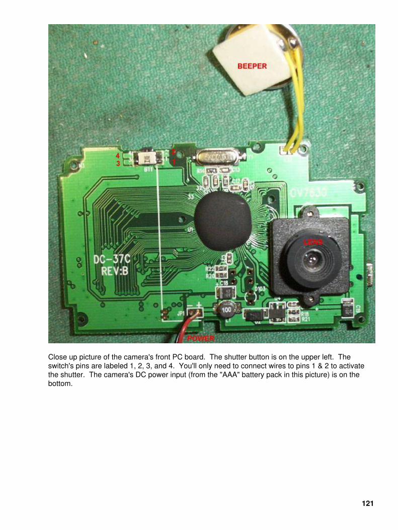
Close up picture of the camera's front PC board. The shutter button is on the upper left. Theswitch's pins are labeled 1, 2, 3, and 4. You'll only need to connect wires to pins 1 & 2 to activatethe shutter. The camera's DC power input (from the "AAA" battery pack in this picture) is on thebottom.
121

Close up picture of the camera's back PC board. The select/power button is on the upper left (PCBmount). The two screws on the left hold the plastic lens assembly to the PC board. The exposedpads shown in the middle of the picture are for the camera's LCD screen. Be very careful removingthis, as they tend to never work right after removing them. The LCD screen is not needed for thecamera's operation, and can be discarded. The large black IC is the camera's main memory. Notethe small 3V lithium cell for memory backup. The input connector on the left is for the computertransfer cable.
555−based shutter button control using all surface mount components. This allows the timer tomounted inside the camera. DC power is from the top (near the 555's pin−8). The output from thebottom 2N3904 goes to shutter button pin−2. Ground goes to the separate 6V power supply andshutter button pin−1.
122

Close up picture of the camera's front PC board with the plastic lens assembly removed. Be sure tonot get any dust on the CMOS imager's window.
Internal picture with everything hooked up. The beeper, eyepiece, and internal battery pack havebeen removed. The wires going out the bottom are for the separate DC power supplies. The yellowwires connect the shutter button to the control timer.
123

Example photo from the Vivitar Vivicam 3350B digital camera in High Quality (VGA) resolutionmode.
Example photo from the Vivitar Vivicam 3350B digital camera in Low Quality (QVGA) resolutionmode.
124

125

126

Bonus
127

End of Issue #12
Any Questions?
Editorial and Rants
Re:What types of phones? (Score:4, Informative)by isometrick (817436) on Wednesday January 12, @08:23AM (#11333812)(Last Journal: Thursday December 16, @01:08AM)
The RF phase modulator is tuned at a slightly different phase angle in GSM basedhandsets, resulting in wavelengths that have more difficulty penetrating the epidermis.
Duh!
If you ever post on Slashdot, please kill yourself.
If you ever mod up this crap on Slashdot, please kill yourself.
Below is a message I found on the IIRG Computer Security Group Yahoo mailing list:(http://groups.yahoo.com/group/iirgsecurity). It's quite interesting and accurate.
Date: Thu Jul 22, 2004 3:04 amSubject: Connecticut 2600 or lack there of....
First and foremost, the IIRG considers it of the upmostimportantance to keep on learning and educating yourself at alltimes.
2600 magazine no longer fosters a sense of community and censorswhat they will and will not publish. It is impossible for anyone tolearn or educate themselves with their current standards.
128

Personally, I will not have any affiliation wirh 2600 Magazineanymore because of Corley's socialist attitutes.
Over 50% of IIRG members are veterans who have been thru the systemand have a sense of community that the IIRG provides. I have spokenat length with our membership and they will NOT support anythingthat is affiliated with 2600 magazine or Eric Corley.
The IIRG has gone above and beyond the call of duty for 2600 in thepast. One of our members spoke at the first HOPE conference. One ofour members organized one of the first 2600 meetings. I personallyorganized the original Meriden 2600 meetings. They republished oneof our Tech Journals and conveniently left out any mention of us.
This is but a small list of grievances relating to 2600 that we have.If an underground meeting was organized that was not affiliated with2600, the IIRG would offer technical support at any time.
I would suggest something like this,−−−−−−−−−−−−−−−−−−−−−−−−−−−−−−−−−−−−−−−−−−−−−−−−−−−−−−−−−−−−−−−−−−−−−Are you Sick of BULLSHIT?Do you like the concept of 2600 Magazine, but aren't a communistsympathizer?Do you like the idea of actually learning something and not justbeing a script kiddie?
Then come to the first meeting of C.H.A.T.
The Connecticut Hackers and Technicians will meet at XXXX on XXXX
We will be chatting about hacking, phreaking, modding, wireless ,andcellular among other things.−−−−−−−−−−−−−−−−−−−−−−−−−−−−−−−−−−−−−−−−−−−−−−−−−−−−−−−−−−−−−−−−−−−−−
This is just an made up example of something that individuals withsome iniative could accomplish. Make up a name and run with it.Eric Corley is NOT the supreme leader of the computer hackercommunity. Be an original, not a copy−cat. You don't have to toaffiliate yourself with 2600 anymore to have a succesful meeting.
If and when a meeting starts with this criteria, the IIRG will offerour support. Until that time we will keep our activities restrictedto our own interests and projects.
Mercenary/IIRG
129

ERROR!There was a error on page 8 of GBPPR 'Zine, Issue #8. The correct TSTLCONT.TLNOS table isshown below:
−−−−−−−−−−−−−−−−−−−−−−−−−−−−−−−−−−−−−−−−−−−−−−−−−−−−−−−−−−−−−−−−−−−−−−−−−−−−−−−−−−−−−−−−−Field Entry Explanation−−−−−−−−−−−−−−−−−−−−−−−−−−−−−−−−−−−−−−−−−−−−−−−−−−−−−−−−−−−−−−−−−−−−−−−−−−−−−−−−−−−−−−−−−TESTLINE alphanumeric Test Line Name (4 characters) Enter the standard DMS test line name. Use the Command Interpreter (CI) command RANGE to obtain the standard DMS test line codes. See the table "Test Lines" in section "Functional Description" for a description of the test lines.−−−−−−−−−−−−−−−−−−−−−−−−−−−−−−−−−−−−−−−−−−−−−−−−−−−−−−−−−−−−−−−−−−−−−−−−−−−−−−−−−−−−−−−−−TLNUMBER 0 to 9, Test Line Number B to F If the switching unit is other than a DMS−300, enter (up to 12 the digits of the test line number that are to be characters) outpulsed (not including the prefix digits from table CLLIMTCE).
If the switching unit is a DMS−300, with a signaling system other than CCIS7, enter KP (Key Pulse), the digits of the test line number (maximum 12) that are to be outpulsed, and ST (Signaling Terminal). KP1 is represented by entry D; KP2 is represented by entry E; ST is represented by entry F.
The first digit position in the test line number following KP, for No. 6 signaling trunks, is the Calling Party's Category Indicator (CPCI) with the following values:
Entry Decimal Value 1 to 9 1 to 9 0 10 B 11 C 12 D 13 E 14 F 15
If the switching unit is a DMS−300, and CCITT7 signaling system, the recommended value for a T100 test line is 64.
Note: The test line number entered in this field applies to the test name entered in field TESTLINE as well as all subset test names associated with the test name as listed in a table, section "Standard DMS Test Names". For example, if T105 is entered as the test line name in field TESTLINE, the test line number entered in field TLNUMBER will apply to the T105 test as well as all its subset tests (such as T164 and TERL).−−−−−−−−−−−−−−−−−−−−−−−−−−−−−−−−−−−−−−−−−−−−−−−−−−−−−−−−−−−−−−−−−−−−−−−−−−−−−−−−−−−−−−−−−TL_MFC_OG_SIG N Test Line Multifrequency Compelled Signal This field is used to test for Multifrequency Compelled (MFC) trunks. Enter N.−−−−−−−−−−−−−−−−−−−−−−−−−−−−−−−−−−−−−−−−−−−−−−−−−−−−−−−−−−−−−−−−−−−−−−−−−−−−−−−−−−−−−−−−−−End−
130