gc max-span n details 3 template - gamechangesolar.com
TRANSCRIPT
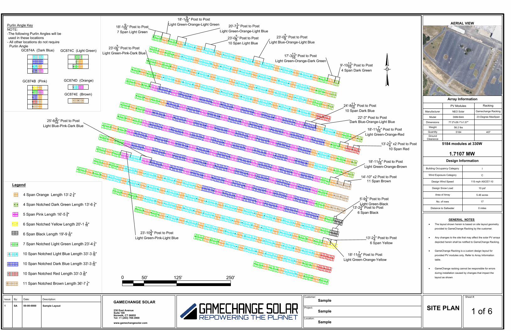
AERIAL VIEW
Issue: By: Date: Description:
Array Information
PV Modules Racking
Manufacturer NEO Solar Gamechange Racking
Model D6M-B4A 23-Degree MaxSpan
Dimensions 77.0"x39.1"x1.57"
Weight 56.2 lbs
Quantity 5184 407Ground
Clearance
Design Information
Building Occupancy Category I
Wind Exposure Category C
Design Wind Speed 115 mph ASCE7-10
Design Snow Load 10 psf
Area of Array 5.46 acres
No. of rows 17
Distance to Saltwater 0 miles
5184 modules at 330W
1.7107 MW
GENERAL NOTES
• The layout shown herein is based on site layout geometry
provided to GameChange Racking by the customer.
• Any changes to the site that may affect the solar PV arrays
depicted herein shall be notified to GameChange Racking.
• GameChange Racking is a custom design layout for
provided PV modules only. Refer to Array Information
table.
• GameChange racking cannot be responsible for errors
during installation caused by changes that impact the
layout as shown
Sheet #:
1 of 6 SITE PLAN
Customer:Sample
Project:Sample
Location:Sample
1 SA 00-00-0000 Sample Layout
GAMECHANGE SOLAR
230 East AvenueSuite 100Norwalk, CT 06855Tel: +1 (203) 769-3900
www.gamechangesolar.com

AERIAL VIEW
Array Information
PV Modules Racking
Manufacturer NEO Solar Gamechange Racking
Model D6M-B4A 23-Degree MaxSpan
Dimensions 77.0"x39.1"x1.57"
Weight 56.2 lbs
Quantity 5184 407Ground
Clearance
Design Information
Building Occupancy Category I
Wind Exposure Category C
Design Wind Speed 115 mph ASCE7-10
Design Snow Load 10 psf
Area of Array 5.46 acres
No. of rows 17
Distance to Saltwater 0 miles
5184 modules at 330W
1.7107 MW
GENERAL NOTES
• The layout shown herein is based on site layout geometry
provided to GameChange Racking by the customer.
• Any changes to the site that may affect the solar PV arrays
depicted herein shall be notified to GameChange Racking.
• GameChange Racking is a custom design layout for
provided PV modules only. Refer to Array Information
table.
• GameChange racking cannot be responsible for errors
during installation caused by changes that impact the
layout as shown
Sheet #:
2 of 6 SITE PLAN
GAMECHANGE SOLAR
230 East AvenueSuite 100Norwalk, CT 06855Tel: +1 (203) 769-3900
www.gamechangesolar.com
Issue: By: Date: Description: Customer:
Sample
Project:Sample
Location:Sample
1 SA 00-00-0000 Sample Layout

AERIAL VIEW
Array Information
PV Modules Racking
Manufacturer NEO Solar Gamechange Racking
Model D6M-B4A 23-Degree MaxSpan
Dimensions 77.0"x39.1"x1.57"
Weight 56.2 lbs
Quantity 5184 407Ground
Clearance
Design Information
Building Occupancy Category I
Wind Exposure Category C
Design Wind Speed 115 mph ASCE7-10
Design Snow Load 10 psf
Area of Array 5.46 acres
No. of rows 17
Distance to Saltwater 0 miles
5184 modules at 330W
1.7107 MW
GENERAL NOTES
• The layout shown herein is based on site layout geometry
provided to GameChange Racking by the customer.
• Any changes to the site that may affect the solar PV arrays
depicted herein shall be notified to GameChange Racking.
• GameChange Racking is a custom design layout for
provided PV modules only. Refer to Array Information
table.
• GameChange racking cannot be responsible for errors
during installation caused by changes that impact the
layout as shown
Sheet #:
3 of 6 Assembly
Drawing
GAMECHANGE SOLAR
230 East AvenueSuite 100Norwalk, CT 06855Tel: +1 (203) 769-3900
www.gamechangesolar.com
Issue: By: Date: Description: Customer:
Sample
Project:Sample
Location:Sample
1 SA 00-00-0000 Sample Layout
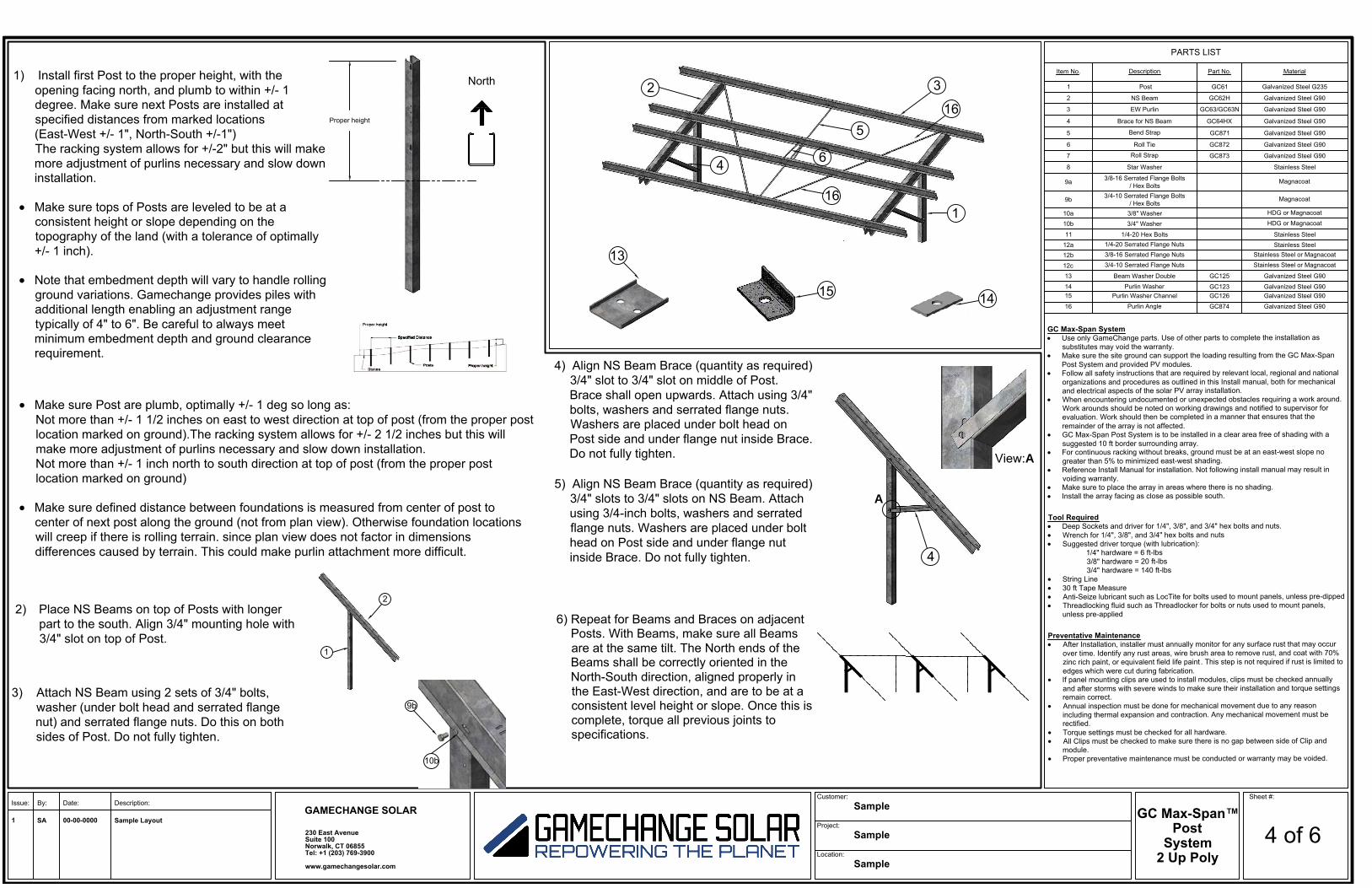
6) Repeat for Beams and Braces on adjacentPosts. With Beams, make sure all Beamsare at the same tilt. The North ends of theBeams shall be correctly oriented in theNorth-South direction, aligned properly inthe East-West direction, and are to be at aconsistent level height or slope. Once this iscomplete, torque all previous joints tospecifications.
4
4) Align NS Beam Brace (quantity as required)3/4" slot to 3/4" slot on middle of Post.Brace shall open upwards. Attach using 3/4"bolts, washers and serrated flange nuts.Washers are placed under bolt head onPost side and under flange nut inside Brace.Do not fully tighten.
5) Align NS Beam Brace (quantity as required)3/4" slots to 3/4" slots on NS Beam. Attachusing 3/4-inch bolts, washers and serratedflange nuts. Washers are placed under bolthead on Post side and under flange nutinside Brace. Do not fully tighten.
A
View:A
Sheet #:
4 of 6
1
2 3
4
5
6
14
13
15
16
PARTS LIST
Item No. Description Part No. Material
1 Post GC61 Galvanized Steel G235
2 NS Beam GC62H Galvanized Steel G90
3 EW Purlin GC63/GC63N Galvanized Steel G90
4 Brace for NS Beam GC64HX Galvanized Steel G90
5 Bend Strap GC871 Galvanized Steel G90
6 Roll Tie GC872 Galvanized Steel G90
7 Roll Strap GC873 Galvanized Steel G90
8 Star Washer Stainless Steel
9a 3/8-16 Serrated Flange Bolts/ Hex Bolts
Magnacoat
9b 3/4-10 Serrated Flange Bolts/ Hex Bolts
Magnacoat
10a 3/8" Washer HDG or Magnacoat
10b 3/4" Washer HDG or Magnacoat
11 1/4-20 Hex Bolts Stainless Steel12a 1/4-20 Serrated Flange Nuts Stainless Steel12b 3/8-16 Serrated Flange Nuts Stainless Steel or Magnacoat
12c 3/4-10 Serrated Flange Nuts Stainless Steel or Magnacoat
13 Beam Washer Double GC125 Galvanized Steel G9014 Purlin Washer GC123 Galvanized Steel G9015 Purlin Washer Channel GC126 Galvanized Steel G9016 Purlin Angle GC874 Galvanized Steel G90
1) Install first Post to the proper height, with theopening facing north, and plumb to within +/- 1degree. Make sure next Posts are installed atspecified distances from marked locations(East-West +/- 1", North-South +/-1")The racking system allows for +/-2" but this will makemore adjustment of purlins necessary and slow downinstallation.
• Make sure tops of Posts are leveled to be at aconsistent height or slope depending on thetopography of the land (with a tolerance of optimally+/- 1 inch).
• Note that embedment depth will vary to handle rollingground variations. Gamechange provides piles withadditional length enabling an adjustment rangetypically of 4" to 6". Be careful to always meetminimum embedment depth and ground clearancerequirement.
Proper height
2) Place NS Beams on top of Posts with longerpart to the south. Align 3/4" mounting hole with3/4" slot on top of Post.
9b
1
2
3) Attach NS Beam using 2 sets of 3/4" bolts,washer (under bolt head and serrated flangenut) and serrated flange nuts. Do this on bothsides of Post. Do not fully tighten.
10b
North
• Make sure Post are plumb, optimally +/- 1 deg so long as:Not more than +/- 1 1/2 inches on east to west direction at top of post (from the proper postlocation marked on ground).The racking system allows for +/- 2 1/2 inches but this willmake more adjustment of purlins necessary and slow down installation.Not more than +/- 1 inch north to south direction at top of post (from the proper postlocation marked on ground)
• Make sure defined distance between foundations is measured from center of post tocenter of next post along the ground (not from plan view). Otherwise foundation locationswill creep if there is rolling terrain. since plan view does not factor in dimensionsdifferences caused by terrain. This could make purlin attachment more difficult.
16
GC Max-Span™
Post
System
2 Up Poly
GAMECHANGE SOLAR
230 East AvenueSuite 100Norwalk, CT 06855Tel: +1 (203) 769-3900
www.gamechangesolar.com
Issue: By: Date: Description: Customer:
Sample
Project:Sample
Location:Sample
1 SA 00-00-0000 Sample Layout
GC Max-Span System
• Use only GameChange parts. Use of other parts to complete the installation assubstitutes may void the warranty.
• Make sure the site ground can support the loading resulting from the GC Max-SpanPost System and provided PV modules.
• Follow all safety instructions that are required by relevant local, regional and nationalorganizations and procedures as outlined in this Install manual, both for mechanicaland electrical aspects of the solar PV array installation.
• When encountering undocumented or unexpected obstacles requiring a work around.Work arounds should be noted on working drawings and notified to supervisor forevaluation. Work should then be completed in a manner that ensures that theremainder of the array is not affected.
• GC Max-Span Post System is to be installed in a clear area free of shading with asuggested 10 ft border surrounding array.
• For continuous racking without breaks, ground must be at an east-west slope nogreater than 5% to minimized east-west shading.
• Reference Install Manual for installation. Not following install manual may result invoiding warranty.
• Make sure to place the array in areas where there is no shading.• Install the array facing as close as possible south.
Tool Required
• Deep Sockets and driver for 1/4", 3/8", and 3/4" hex bolts and nuts.• Wrench for 1/4", 3/8", and 3/4" hex bolts and nuts• Suggested driver torque (with lubrication):
1/4" hardware = 6 ft-lbs 3/8" hardware = 20 ft-lbs3/4" hardware = 140 ft-lbs
• String Line• 30 ft Tape Measure• Anti-Seize lubricant such as LocTite for bolts used to mount panels, unless pre-dipped• Threadlocking fluid such as Threadlocker for bolts or nuts used to mount panels,
unless pre-applied
Preventative Maintenance
• After Installation, installer must annually monitor for any surface rust that may occurover time. Identify any rust areas, wire brush area to remove rust, and coat with 70%zinc rich paint, or equivalent field life paint . This step is not required if rust is limited toedges which were cut during fabrication.
• If panel mounting clips are used to install modules, clips must be checked annuallyand after storms with severe winds to make sure their installation and torque settingsremain correct.
• Annual inspection must be done for mechanical movement due to any reasonincluding thermal expansion and contraction. Any mechanical movement must berectified.
• Torque settings must be checked for all hardware.• All Clips must be checked to make sure there is no gap between side of Clip and
module.• Proper preventative maintenance must be conducted or warranty may be voided.

Continuous System
Sheet #:
5 of 6
See Step 8 for Connection
5 6
16
9) Attach Bend Straps, Roll Ties, Roll Straps, and Purlin Angles as required. Use 3/8"bolts and serrated flange nuts to attach. Make sure all hardware is tightened to propertorque settings.This is a general guideline only, please refer to install manual whichmust be followed for proper installation or warranty may be voided.The Purlin-to-Beam Supports and Purlin to Purlin must be taut, this is very important
7
PARTS LIST
Item No. Description Part No. Material
1 Post GC61 Galvanized Steel G235
2 NS Beam GC62H Galvanized Steel G90
3 EW Purlin GC63/GC63N Galvanized Steel G90
4 Brace for NS Beam GC64HX Galvanized Steel G90
5 Bend Strap GC871 Galvanized Steel G90
6 Roll Tie GC872 Galvanized Steel G90
7 Roll Strap GC873 Galvanized Steel G90
8 Star Washer Stainless Steel
9a 3/8-16 Serrated Flange Bolts/ Hex Bolts
Magnacoat
9b 3/4-10 Serrated Flange Bolts/ Hex Bolts
Magnacoat
10a 3/8" Washer HDG or Magnacoat
10b 3/4" Washer HDG or Magnacoat
11 1/4-20 Hex Bolts Stainless Steel12a 1/4-20 Serrated Flange Nuts Stainless Steel12b 3/8-16 Serrated Flange Nuts Stainless Steel or Magnacoat
12c 3/4-10 Serrated Flange Nuts Stainless Steel or Magnacoat
13 Beam Washer Double GC125 Galvanized Steel G9014 Purlin Washer GC123 Galvanized Steel G9015 Purlin Washer Channel GC126 Galvanized Steel G9016 Purlin Angle GC874 Galvanized Steel G90
13
9a
15
8) For continuous configurations, Purlinends shall be connected together using3/8"bolts (serrated head or not), washersand serrated flange nuts. Torque tospecifications. When floating Purlinconnect to table Purlins, there will be anominal drop of 1/8 to 1/4 inch from onePurlin to the next, which will result in asmall corresponding drop from one panelto the next. This is normal, and is not ashading or functional issue.
7) Attach EW Purlins to NS Beamsusing 3/8-inch bolts and serratedflange nuts. EW Purlins should beattached with 2 bolts. Place aBeam Washer Double on the underside of the Beam. Place a PurlinWasher under the hex bolt closerto the Purlin wall while the hex boltfurther from the Purlin wall onlyreceives a flange nut. Tightenhardware to specification.Alternatively bolts may come upand flange nuts be above Purlins.
If Purlin Channel Washers areprovided as an alternate to PurlinWashers, be sure that the bentflange is bearing against the Purlinwall prior to torquing the hardware.It is essential to always use PurlinChannel Washers with 16 GaugePurlins
9a
14
13
12b9a
10a
B DC
12b
View:B
Purlin Angle to EW PurlinRoll Strap to EW
Purlin and NS Beam
9a
12b
12b
Roll Tie and BendStrap to EW Purlin
GC Max-Span™
Post
System
2 Up Poly
View:C
View:D
9a
9a
16
12b
12b
GAMECHANGE SOLAR
230 East AvenueSuite 100Norwalk, CT 06855Tel: +1 (203) 769-3900
www.gamechangesolar.com
Issue: By: Date: Description: Customer:
Sample
Project:Sample
Location:Sample
1 SA 00-00-0000 Sample Layout
GC Max-Span System
• Use only GameChange parts. Use of other parts to complete the installation assubstitutes may void the warranty.
• Make sure the site ground can support the loading resulting from the GC Max-SpanPost System and provided PV modules.
• Follow all safety instructions that are required by relevant local, regional and nationalorganizations and procedures as outlined in this Install manual, both for mechanicaland electrical aspects of the solar PV array installation.
• When encountering undocumented or unexpected obstacles requiring a work around.Work arounds should be noted on working drawings and notified to supervisor forevaluation. Work should then be completed in a manner that ensures that theremainder of the array is not affected.
• GC Max-Span Post System is to be installed in a clear area free of shading with asuggested 10 ft border surrounding array.
• For continuous racking without breaks, ground must be at an east-west slope nogreater than 5% to minimized east-west shading.
• Reference Install Manual for installation. Not following install manual may result invoiding warranty.
• Make sure to place the array in areas where there is no shading.• Install the array facing as close as possible south.
Tool Required
• Deep Sockets and driver for 1/4", 3/8", and 3/4" hex bolts and nuts.• Wrench for 1/4", 3/8", and 3/4" hex bolts and nuts• Suggested driver torque (with lubrication):
1/4" hardware = 6 ft-lbs 3/8" hardware = 20 ft-lbs3/4" hardware = 140 ft-lbs
• String Line• 30 ft Tape Measure• Anti-Seize lubricant such as LocTite for bolts used to mount panels, unless pre-dipped• Threadlocking fluid such as Threadlocker for bolts or nuts used to mount panels,
unless pre-applied
Preventative Maintenance
• After Installation, installer must annually monitor for any surface rust that may occurover time. Identify any rust areas, wire brush area to remove rust, and coat with 70%zinc rich paint, or equivalent field life paint . This step is not required if rust is limited toedges which were cut during fabrication.
• If panel mounting clips are used to install modules, clips must be checked annuallyand after storms with severe winds to make sure their installation and torque settingsremain correct.
• Annual inspection must be done for mechanical movement due to any reasonincluding thermal expansion and contraction. Any mechanical movement must berectified.
• Torque settings must be checked for all hardware.• All Clips must be checked to make sure there is no gap between side of Clip and
module.• Proper preventative maintenance must be conducted or warranty may be voided.
Sheet #:
6 of 6
12) The modules, EW Purlins and NS Beams are all bonded together, left to right, sothat each row form one single structure. GameChange recommends up to 16 stringsmay be grounded on one grounding lug which should be attached at the holeprovided next to the marking “GROUND”. Install Cooper, Burndy, or Eaton. ULapproved grounding lug with 1/4-inch bolts as in accordance with NEC Article 690 tothe end of the last EW Purlin which has panels attached to it which are to be bonded,using 8 gauge copper wire. Repeat for each 16 strings.
The entire system needs to be grounded from a single point to an appropriategrounding source.**Please confirm with an electrician, as this is their responsibility**
10) Attach first panel to EW Purlin through mounting holes nearest to NS Beam. Place astar washer at one mounting location per panel. Insert hex bolt through the Purlin, themounting hole on the back of the panel, and then through the star washer. Attach witha serrated flange nuts on the bolt end inside the panel. Check again to make sure starwasher is still in place. Torque to specifications. Repeat for all panels.
11) For bottom mount attachment of panels GameChange typically provides slotted panelmounting holes to enable panel adjustment in case purlins are not perfectly aligneddue to rolling or otherwise uneven ground situations. It is the customer's responsibilityto make sure to follow panel spacing guidelines if any are given by panel vendor intheir specification sheet or elsewhere, otherwise panel warranty could be voided. In allcases make sure panel spacing is the greater of 1/8 inch or the minimum called out bythe panel vendor. This will allow for thermal expansion of panels. GameChangesystems typically enable 1/2 inch panel spacing if aligned properly. Spacing betweenpanels can be set by placing a temporary spacer such as bolt shaft or plywood ofsame thickness as required for panel spacing between panels while they are beinginstalled. This spacer should be removed after panel installation is complete.
PARTS LIST
Item No. Description Part No. Material
1 Post GC61 Galvanized Steel G235
2 NS Beam GC62H Galvanized Steel G90
3 EW Purlin GC63/GC63N Galvanized Steel G90
4 Brace for NS Beam GC64HX Galvanized Steel G90
5 Bend Strap GC871 Galvanized Steel G90
6 Roll Tie GC872 Galvanized Steel G90
7 Roll Strap GC873 Galvanized Steel G90
8 Star Washer Stainless Steel
9a 3/8-16 Serrated Flange Bolts/ Hex Bolts
Magnacoat
9b 3/4-10 Serrated Flange Bolts/ Hex Bolts
Magnacoat
10a 3/8" Washer HDG or Magnacoat
10b 3/4" Washer HDG or Magnacoat
11 1/4-20 Hex Bolts Stainless Steel12a 1/4-20 Serrated Flange Nuts Stainless Steel12b 3/8-16 Serrated Flange Nuts Stainless Steel or Magnacoat
12c 3/4-10 Serrated Flange Nuts Stainless Steel or Magnacoat
13 Beam Washer Double GC125 Galvanized Steel G9014 Purlin Washer GC123 Galvanized Steel G9015 Purlin Washer Channel GC126 Galvanized Steel G9016 Purlin Angle GC874 Galvanized Steel G90
12a
11
8
GC Max-Span™
Post
System
2 Up Poly
GAMECHANGE SOLAR
230 East AvenueSuite 100Norwalk, CT 06855Tel: +1 (203) 769-3900
www.gamechangesolar.com
Issue: By: Date: Description: Customer:
Sample
Project:Sample
Location:Sample
1 SA 00-00-0000 Sample Layout