gcse electronic products revision flashcards. 555 timer 8 pin integrated circuit (i.c.) analog can...
TRANSCRIPT
GCSE Electronic Products
Revision Flashcards

555 timer
•8 pin Integrated Circuit (I.C.)•Analog•can be used as an astable or monostable•Low cost

Monostable(the egg timer)
•Has a single (mono) stable state• when it is timing
•The output is normally off

Pin 2 = Trigger
• The trigger sets the timer going
• Timer starts when trigger is < 2V
• Connects to a 10K pull-up resistor
Pull-up resistor
• Pulls the voltage up on a wire to supply voltage
• Makes a “nice” logic high

Pull Down Resistor
• Pulls the voltage on a wire down to 0V
• Gives a “nice” logic 0

Pin 6 = Threshold• Detects when the bucket
(capacitor) is 2/3rds full
• The capacitor fills up through a resistor
• Time to fill to 2/3rds full = Resistor Value x Capacitor Value (T = RC)

Pin 7 = discharge
• Empties the bucket (capacitor)
Astable(The “flasher” circuit)
• Has no stable states
• Keeps on flashing forever
• Number of flashes per second = frequency
• Automatically triggers

The Op-Amp• - input = inverting
• + input = non-inverting
• used as an inverting amplifier or a comparator
• An analog device
• A 741 I.C. is an example of an op-amp

Inverting
• Means it turns the signal upside down
Gain• The ability of a device
to make a signal bigger
• Op-amps have huge “open loop” gain
• Transistors also have gain
Feedback• Gain can be reduced by
using feedback
• Some of the output is taken away and added to the input
• We use resistors to do this

Comparator(Which input is bigger)
• If “+” is bigger than “-” we get a logic 1
• If “+” is smaller than “-” then we get a logic 0
• A simple analog to digital converter
+ -

Ohms Law
• As resistance increases, current decreases
• As resistance increases, voltage increases

Sources of power

P.I.C.(Peripheral Interface Controller)
• Digital• A mini-computer in a
single Integrated Circuit• Programmable using
flowcharts• Can be programmed many
times• Remembers program even
when the power is off

Diode(A one way valve)
• Current flows from anode to cathode
• Prevents current flowing the wrong way
• Protects circuits if the power supply is connected up wrong

Transducer(A device for converting energy
from one form to another• Motor – converts electrical
energy to kinetic energy• LED – converts electrical
energy to light• Microphone - converts
sound energy to electrical energy

Transducer Drivers(Things that provide power to output transducers)
• Bipolar Transistors• FET’s• Darlington Pairs

Tolerance
• The amount of “spread” in a components value
• 100Ω and 10% tolerance gives a spread between 90Ω and 110Ω

E12 Series
• The values that 10% tolerance resistors are made in to avoid value overlap
• 10, 12, 15, 18, 22 etc• 100, 120, 150, 180 etc

Polymorph – Smart Material
• Used to rapidly model complex shapes
• Granules put in hot water turn solid and can be immediately shaped
+

clock
• A digital signal that has a regular repeating on/off pattern
• Often generated by an astable
• Used by PICs & counters

HIPS
• Plastic material used for vacuum forming
• Available in different colours
• Used to make complex 3d shapes
• Boxes must have angled sides to get the mold out

Breadboard
• Used to model circuit using real component
• No soldering• Easy to change
connections• Components can be re-
used
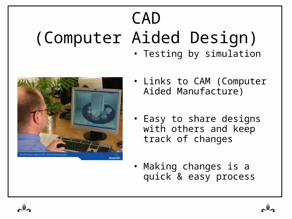
CAD(Computer Aided Design)
• Testing by simulation
• Links to CAM (Computer Aided Manufacture)
• Easy to share designs with others and keep track of changes
• Making changes is a quick & easy process

Latch Circuit• Can be made using a
thyristor
• Can be made with NOR or NAND gates
• When activated, stays activated until reset– Remembers that it has
been activated

Thyristor• Used in latch circuits
• A pulse on the gate causes current to flow from Anode to Cathode until reset
• Reset by making the Anode voltage the same as the Cathode

Potential Divider
• A circuit for dividing voltages
• Voltage splits based upon the ratio of two resistors

Schmitt Trigger
• A type of circuit used to remove switch bounce

Thermistor• Device for measuring
temperature
• As temperature increases, resistance decreases
• Often used as part of a potential divider

LDR(Light Dependent Resistor)
• As light increases, resistance decreases
• Often used as part of a potential divider
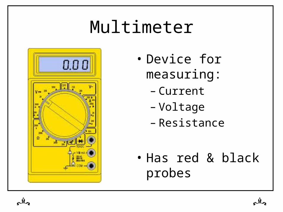
Multimeter
• Device for measuring:– Current– Voltage– Resistance
• Has red & black probes

The 3 R’s(Helping The Environment)
• Reducecut the materials you use
• Reusemake use of existing products
• Recyclestop the product going to landfill when obsolete

Resistors• Measured in Ohms
(Ω)
• Used to reduce current
• Colour bands indicate the value

Integrated Circuits
• Pin 1 is to the left of the notch
• Lots of components on a single piece of silicon
• Examples are:– PICS– 555’s– 741’s

Switch Bounce
• A problem with mechanical PTM & PTB switches
• One press of the switch generates more than one pulse

AND Gate
• Both inputs must be at logic 1 to get a logic 1 out
• A = 1 AND B= 1

OR GATE
• Either one of the two inputs can be at logic 1 to create a 1 on the output
• A=1 OR B=1

Relay
• A device that allows one circuit to turn on another circuit that works at a different voltage
• Uses electro-magnets

Variable Resistor
• Used for– volume controls
– Changing astable frequencies
– Changing mono-stable time periods

4017• Output 0 is on• When a clock pulse is
received:– Output0 turns off– Output1 turns on
• On next clock pulse– Output1 turns off– Output2 turns on

SPDT SWITCH(Single Pole Double Throw)
• One circuit• Two positions• Three pins• Two different sets of
components can be switched into one circuit

Life Cycle Analysis
• What happens to a product when it is disposed of:
– Reused in a new product
– Recycled– Goes to landfill

Multipliers
1,000,000,000 = 1G = 1 x 10⁹
1,000,000 = 1M = 1 x 10⁶
1,000 = 1K = 1 x 10³
1 = 1 = 1 x 101
0.001 = 1m = 1 x 10⁻³
0.000,001 = 1µ = 1 x 10⁻⁶
0.000,000,001 = 1n = 1 x 10⁻⁹
0.000,000,000,001 = 1p = 1 x 10-12

Units of MeasureMeasurement Unit Symbol
Resistance Ohms Ω
Capacitance Farads F
Voltage Volts V
Current Amps I
Power Watts W
Time Seconds S