gd8 1600 exposed burner - the fire dept. · front view - fire insert (wall framing) s ha der...
TRANSCRIPT

GD8 – 1600 Exposed Burner
Specifications

GSPublisherEngine 0.2.100.100
CO
PYR
IGH
T©TH
IS D
RAW
ING
IS T
HE
PRO
PER
TY
OF T
he F
ire
Dep
t.
Client:Product:
Title:Drawn:Chkd:Appd:
Date:Date:Date:
Drawing No. Sheet of Revision
Scale: on
0
THE FIRE DEPT.
A4
910
450
50
610 22
390 120 100 22
1,804
eq eq
2210
012
039
0
158
604
148
25 75 1,604 75 25
1,400 - grate
25 75 1,604 75 25
1,804
158
604
148
450
50
1,41
0
Information in this specification may be subject tochange without notice. Please ensure you have thecurrent version before beginning installation.
Front ViewSide View
635 min.
NOTE:Framing to opening oncefire installed
Fire Installation - Trim Sizes
225
Fixing holes forM6 bolts - checkon site
NOTE: Confirm fixing holes on site prior to drilling
205
eq1,804
650
eq
NOTE:Power andgas to thislocation
1,435 - min.to framing
GD8-1600-Exposed Burner
FIREBOX DIMENSIONS03/05/2018
GD8-1600-901EB 01
TOLERANCE = +/- 3mm
SRJWJW
10 3
03/05/201803/05/2018

GSPublisherEngine 0.2.100.100
CO
PYR
IGH
T©TH
IS D
RAW
ING
IS T
HE
PRO
PER
TY
OF T
he F
ire
Dep
t.
Client:Product:
Title:Drawn:Chkd:Appd:
Date:Date:Date:
Drawing No. Sheet of Revision
Scale: on
0
THE FIRE DEPT.
A4
635
min
.
25 1,754 25
1,43
5 m
in.
610
25
Shaded areacombustiblematerials
Shaded areacombustiblematerials
(clearance totop of opening)
F.L.
Non-combustiblelining shown shaded
Front View - Fire Insert
(wall framing)
Shaded areacombustiblematerials
Shaded areacombustiblematerials
See FireplaceSurroundDetail 1
Plan View - Fire Insert
(clearance toback of opening)
See FireplaceSurroundDetail 1
CAVITY CLEARANCES
02
SRJWJW
GD8-1600-Exposed Burner
GD8-1600-902EB 10
03/05/2018
3
03/05/201803/05/2018

GSPublisherEngine 0.2.100.100
CO
PYR
IGH
T©TH
IS D
RAW
ING
IS T
HE
PRO
PER
TY
OF T
he F
ire
Dep
t.
Client:Product:
Title:Drawn:Chkd:Appd:
Date:Date:Date:
Drawing No. Sheet of Revision
Scale: on
0
THE FIRE DEPT.
A4
1,43
5
635 min.
635 min.
Varie
s1,
435
F.L.
(clearance totop of opening)
Combustiblematerials
Cross Section - Fire Insert at Floor Level
See FireplaceSurround Detail 2
See FireplaceSurround Detail 3
See MantelDetail 4
NOTE:Framing to openingonce fire installed
F.L.
(clearance totop of opening)
Combustiblematerials
Cross Section - Fire Insert at Floor Level
See FireplaceSurround Detail 2
See FireplaceSurround Detail 3
See MantelDetail 4
NOTE:Framing to openingonce fire installed
NOTE:Structure to support fire,design for 350kg load
NOTE: Plinth height can vary to suit
CAVITY CLEARANCES
03
SRJWJW
GD8-1600-Exposed Burner
GD8-1600-903EB 10
03/05/2018
3
03/05/201803/05/2018

GSPublisherEngine 0.2.100.100
CO
PYR
IGH
T©TH
IS D
RAW
ING
IS T
HE
PRO
PER
TY
OF T
he F
ire
Dep
t.
Client:Product:
Title:Drawn:Chkd:Appd:
Date:Date:Date:
Drawing No. Sheet of Revision
Scale: on
0
THE FIRE DEPT.
A4
5
5
50
5
Detail 1 - Plan View Fire Surround
Non-combustiblewall lining
Combustiblematerial
5mm gap tocombustiblematerial
Angle
Angle
Non-combustiblewall lining
Combustiblematerial
5mm gap tocombustiblematerial
NOTE:Framing toopening oncefire installed
Detail 2 - Top of Fire to Combustible Materials
Angle
Non-combustiblewall lining
Combustiblematerial
5mm gap tocombustiblematerial
Detail 3 - Bottom of Fire to Floor Detail 4 - Top of Fire to Combustible Mantel
Angle
(top of fire)
450
NOTE:Combustible mantelto shaded area only
(do no
t plac
e com
busti
ble m
antel
outsi
de th
e sha
ded a
rea)
SURROUND DETAILS
04
SRJWJW
GD8-1600-Exposed Burner
GD8-1600-904EB 10
03/05/2018
3
03/05/201803/05/2018

GSPublisherEngine 0.2.100.100
CO
PYR
IGH
T©TH
IS D
RAW
ING
IS T
HE
PRO
PER
TY
OF T
he F
ire
Dep
t.
Client:Product:
Title:Drawn:Chkd:Appd:
Date:Date:Date:
Drawing No. Sheet of Revision
Scale: on
0
THE FIRE DEPT.
A4
25
9492
24 219 179 50117 161 203
5018
621
1
25
25
25
Casing cover / Top flashing
Cowl
Spacers to maintain 25mmmin. gap between flue pipe /casing / spigot
Roof flashing in accordancewith NZBC or Dektite FlashingNo. 9
Allow air flow from roof cavityout through casing cover
Casing to In-line fan
Flue to In-line fan
Warmair
Roof
Detail - Air Ventilation through Casing cover/ Top flashing- Without Fan
Stainless steelspigot toundersideof roof structure
Flue components:300mm dia. Flue350mm dia. Casing400mm dia. SpigotDektite Flashing No. 9
External wallcowl
Detail - Air Ventilation through Wall
Flue to fire
Casing tofire
Spigot wallplate
Hot air out
Exterior wall
Flue components:150mm dia. Flue200mm dia. Casing250mm dia. Spigot
Wall flashing inaccordancewith NZBC
NOTE:Flue components must be installed to AS/NZS5601 requirements.All external penetration flashings must be installed in accordance with NZBC.Fire supplied with 3m of 5 core wire from fire to fan.Cavity airflow must be unobstructed from fire to flue termination.25mm clearance between flue and combustible materials.75mm clearance between flue and wiring / plastic water pipes.Horizontal flue run must fall 20mm for every 1000mm towards the fire.Each flue joint must be sealed with a heat proof sealer.Each flue joint must have a minimum of 4 x riverts.Flue to be adequately supported at 2.4m crs.
NOTE: Requires access hatch for maintenanceSide viewDetail - In-Line Fan - Front view
c
c c
Casing cover / Top flashing
Cowl
Spacers to maintain 25mmmin. gap between flue pipe /casing / spigot
Roof flashing in accordancewith NZBC or Dektite FlashingNo. 7
Allow air flow from roof cavityout through casing cover
Casing to In-line fan
Flue to In-line fan
Warmair
Roof
Detail - Air Ventilation through Casing cover/ Top flashing- With Fan
Stainless steelspigot toundersideof roof structure
Flue components (from Fire to Fan):300mm dia. Flue350mm dia. Casing400mm dia. Spigot
Flue components (from Fan to Flue Exit):150mm dia. Flue200mm dia. Casing250mm dia. SpigotDektite Flashing No. 7
VERTICAL & HORIZONTAL FLUE EXIT DETAILS
05
SRJWJW
GD8-1600-Exposed Burner
GD8-1600-905EB 10
03/05/2018
3
03/05/201803/05/2018

GSPublisherEngine 0.2.100.100
CO
PYR
IGH
T©TH
IS D
RAW
ING
IS T
HE
PRO
PER
TY
OF T
he F
ire
Dep
t.
Client:Product:
Title:Drawn:Chkd:Appd:
Date:Date:Date:
Drawing No. Sheet of Revision
Scale: on
0
THE FIRE DEPT.
A4
9492
24 219 179 50117 161 203
5018
621
1
680
680
930
456
456
600
Detail - Air Ventilation through Wall
Casing tofire
Spigot wallplate
Hot air out
Flue components:150mm dia. Flue200mm dia. Casing250mm dia. Spigot
NOTE: Requires access hatch for maintenanceSide viewDetail - In-Line Fan - Front view
c
c c
Dektite Flashing No. 9 - Plan View Dektite Flashing No. 7 - Plan View
VERTICAL & HORIZONTAL FLUE EXIT DETAILS
06
SRJWJW
GD8-1600-Exposed Burner
GD8-1600-906EB 10
03/05/2018
3
03/05/201803/05/2018
GSPublisherEngine 0.2.100.100
CO
PYR
IGH
T©TH
IS D
RAW
ING
IS T
HE
PRO
PER
TY
OF T
he F
ire
Dep
t.
Client:Product:
Title:Drawn:Chkd:Appd:
Date:Date:Date:
Drawing No. Sheet of Revision
Scale: on
0
THE FIRE DEPT.
A4
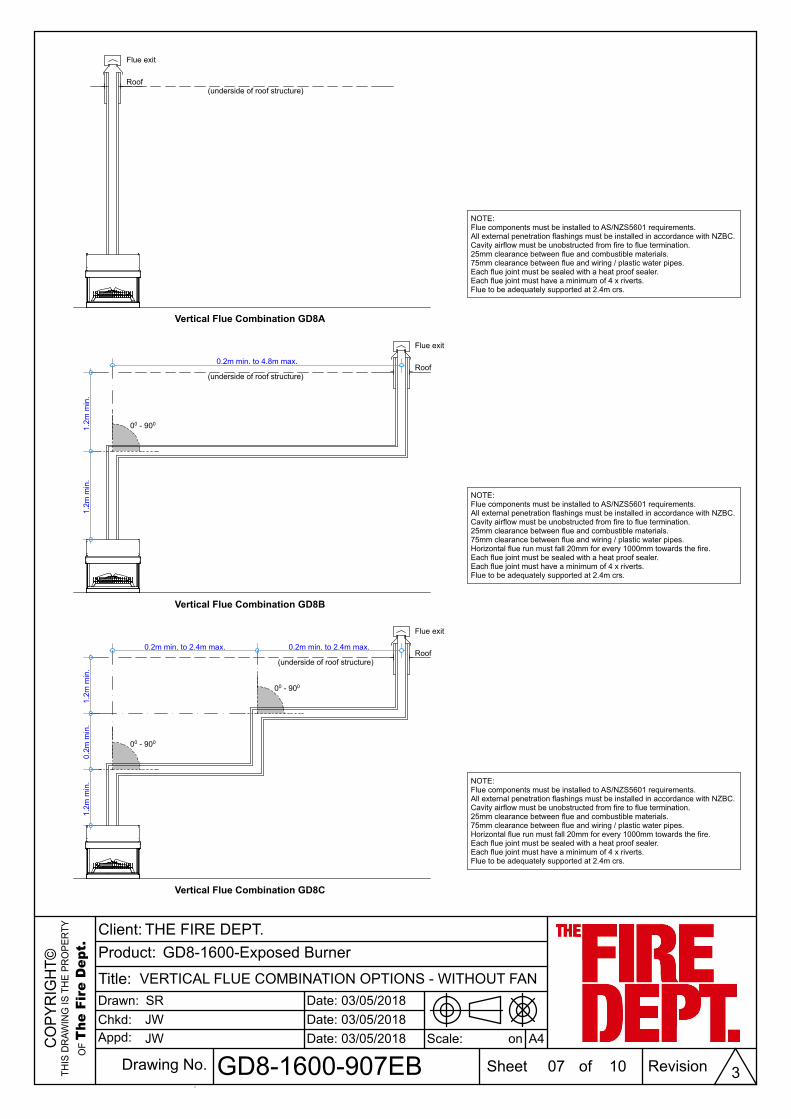
0.2m min. to 4.8m max.
0.2m min. to 2.4m max. 0.2m min. to 2.4m max.
(underside of roof structure)
Vertical Flue Combination GD8C
Vertical Flue Combination GD8B
Flue exit
Roof
Flue exit
Roof
1.2m
min
.
(underside of roof structure)
(underside of roof structure)
Vertical Flue Combination GD8A
Flue exit
Roof
NOTE:Flue components must be installed to AS/NZS5601 requirements.All external penetration flashings must be installed in accordance with NZBC.Cavity airflow must be unobstructed from fire to flue termination.25mm clearance between flue and combustible materials.75mm clearance between flue and wiring / plastic water pipes.Horizontal flue run must fall 20mm for every 1000mm towards the fire.Each flue joint must be sealed with a heat proof sealer.Each flue joint must have a minimum of 4 x riverts.Flue to be adequately supported at 2.4m crs.
NOTE:Flue components must be installed to AS/NZS5601 requirements.All external penetration flashings must be installed in accordance with NZBC.Cavity airflow must be unobstructed from fire to flue termination.25mm clearance between flue and combustible materials.75mm clearance between flue and wiring / plastic water pipes.Horizontal flue run must fall 20mm for every 1000mm towards the fire.Each flue joint must be sealed with a heat proof sealer.Each flue joint must have a minimum of 4 x riverts.Flue to be adequately supported at 2.4m crs.
NOTE:Flue components must be installed to AS/NZS5601 requirements.All external penetration flashings must be installed in accordance with NZBC.Cavity airflow must be unobstructed from fire to flue termination.25mm clearance between flue and combustible materials.75mm clearance between flue and wiring / plastic water pipes.Each flue joint must be sealed with a heat proof sealer.Each flue joint must have a minimum of 4 x riverts.Flue to be adequately supported at 2.4m crs.
00 - 900
00 - 900
00 - 900
1.2m
min
.1.
2m m
in.
0.2m
min
.1.
2m m
in.
VERTICAL FLUE COMBINATION OPTIONS - WITHOUT FAN
07
SRJWJW
GD8-1600-Exposed Burner
GD8-1600-907EB 10
03/05/2018
3
03/05/201803/05/2018

GSPublisherEngine 0.2.100.100
CO
PYR
IGH
T©TH
IS D
RAW
ING
IS T
HE
PRO
PER
TY
OF T
he F
ire
Dep
t.
Client:Product:
Title:Drawn:Chkd:Appd:
Date:Date:Date:
Drawing No. Sheet of Revision
Scale: on
0
THE FIRE DEPT.
A4
0.2m min. to 13.5m max.
0.5m
min
. to
13.8
m m
ax.
0.2m min. to 13.1m max. 0.2m min. to 13.1m max.
0.5m
min
. to
13.4
m m
ax.
0.2m
min
. to
13.1
m m
ax.
NOTE:Maximum total flue length 14m
Horizontal Flue Combination GD8D
Flueexit
Ext
erio
r wal
l
Horizontal Flue Combination GD8E
Flueexit
NOTE:Flue components must be installed to AS/NZS5601 requirements.All external penetration flashings must be installed in accordance with NZBC.Fire supplied with 3m of 5 core wire from fire to fan.Cavity airflow must be unobstructed from fire to flue termination.25mm clearance between flue and combustible materials.75mm clearance between flue and wiring / plastic water pipes.Horizontal flue run must fall 20mm for every 1000mm towards the fire.Each flue joint must be sealed with a heat proof sealer.Each flue joint must have a minimum of 4 x riverts.Flue to be adequately supported at 2.4m crs.
In-LineFan
NOTE:Maximum total flue length 14m
NOTE:Flue components must be installed to AS/NZS5601 requirements.All external penetration flashings must be installed in accordance with NZBC.Fire supplied with 3m of 5 core wire from fire to fan.Cavity airflow must be unobstructed from fire to flue termination.25mm clearance between flue and combustible materials.75mm clearance between flue and wiring / plastic water pipes.Horizontal flue run must fall 20mm for every 1000mm towards the fire.Each flue joint must be sealed with a heat proof sealer.Each flue joint must have a minimum of 4 x riverts.Flue to be adequately supported at 2.4m crs.
In-LineFan
00 - 900
(300
mm
dia
. Flu
e/ 3
50m
m d
ia. C
asin
g)(3
00m
m d
ia. F
lue/
350m
m d
ia. C
asin
g)(3
00m
m d
ia. F
lue/
350m
m d
ia. C
asin
g)
(300mm dia. Flue/ 350mm dia. Casing)
(150mm dia. Flue/ 200mm dia. Casing)
(150mm dia. Flue/ 200mm dia. Casing)
HORIZONTAL FLUE COMBINATION OPTIONS
08
SRJWJW
GD8-1600-Exposed Burner
GD8-1600-908EB 10
03/05/2018
3
03/05/201803/05/2018
GSPublisherEngine 0.2.100.100
CO
PYR
IGH
T©TH
IS D
RAW
ING
IS T
HE
PRO
PER
TY
OF T
he F
ire
Dep
t.
Client:Product:
Title:Drawn:Chkd:Appd:
Date:Date:Date:
Drawing No. Sheet of Revision
Scale: on
0
THE FIRE DEPT.
A4
0.5m
min
. to
12.9
5m m
ax.
0.35
m m
in. t
o 12
.95m
max
.
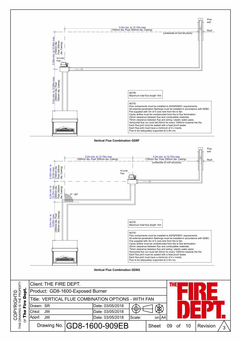
0.2m min. to 13.15m max.
0.2m min. to 12.75m max. 0.2m min. to 12.75m max.
Vertical Flue Combination GD8F
Flueexit
Roof(underside of roof structure)
Vertical Flue Combination GD8G
(underside of roof structure)
0.2m
min
. to
12.7
5m m
ax.
0.35
m m
in. t
o12
.9m
max
.0.
5m m
in. t
o13
.05m
max
.
In-LineFan
In-LineFan
NOTE:Maximum total flue length 14m
NOTE:Flue components must be installed to AS/NZS5601 requirements.All external penetration flashings must be installed in accordance with NZBC.Fire supplied with 3m of 5 core wire from fire to fan.Cavity airflow must be unobstructed from fire to flue termination.25mm clearance between flue and combustible materials.75mm clearance between flue and wiring / plastic water pipes.Horizontal flue run must fall 20mm for every 1000mm towards the fire.Each flue joint must be sealed with a heat proof sealer.Each flue joint must have a minimum of 4 x riverts.Flue to be adequately supported at 2.4m crs.
Flueexit
Roof
00 - 900
(300
mm
dia
. Flu
e/35
0mm
dia
. Cas
ing)
(150mm dia. Flue/ 200mm dia. Casing)
(300
mm
dia
. Flu
e/35
0mm
dia
. Cas
ing)
(300
mm
dia
.Fl
ue/ 3
50m
mdi
a. C
asin
g)
(150mm dia. Flue/ 200mm dia. Casing)(300mm dia. Flue/ 350mm dia. Casing)
(150
mm
dia
.Fl
ue/ 2
00m
mdi
a. C
asin
g)
(150
mm
dia
.Fl
ue/ 2
00m
mdi
a. C
asin
g)
VERTICAL FLUE COMBINATION OPTIONS - WITH FAN
09
SRJWJW
GD8-1600-Exposed Burner
GD8-1600-909EB 10
03/05/2018
3
03/05/201803/05/2018

GSPublisherEngine 0.2.100.100
CO
PYR
IGH
T©TH
IS D
RAW
ING
IS T
HE
PRO
PER
TY
OF T
he F
ire
Dep
t.
Client:Product:
Title:Drawn:Chkd:Appd:
Date:Date:Date:
Drawing No. Sheet of Revision
Scale: on
0
THE FIRE DEPT.
A4
Increase as necessaryuntil nothing within3000 of flue top
Any near by structure
1000 min.if clearwithin 3000of flue top
3000or less
More than 3000
600 min.
3000
3000
3000or less
More than 3000
600 min.
3000Increasefrom 1000min. untilclear within3000 offlue top
Minimum Height of Flue System ExitOr as per AS/NZS 5601
a
b
C
de
f
g
gh
h e
c
d
g jj
j
k
kn
T T
T
TT
ZS
T T
M
IP
T
Opening intoa building
Door
Direction ofdischarge
See Note 1
See Note 1
LEGEND:I = Mechanical air inletM = Gas meterP = Electricity meter or fuse boxS = StructureT = Flue terminalZ = Fan-assisted appliance only
Shading indicates prohibitedarea for flue terminals
Location of Flue Terminals of Balanced Flue,Room-Sealed, Fan-Assisted or Outdoor Appliances
NOTE: To be read in conjunction with AS/NZS 5601.1:2013
a = 200 g = 500b = 300 h = 300c = 300 j = 300 (at window) & 1500d = 1000 (fan-assisted appliance by the door)e = 500 k = 1000f = 75 n = 500
NOTES:Where dimensions c, j or k cannot be achievedan equivalent horizontal distance measureddiagonally from the nearest discharge point of theterminal to the opening may be deemed by theTechnical Regulator to comply.
1
SRJWJW
FLUE EXIT CLEARANCES
10
GD8-1600-Exposed Burner
GD8-1600-910EB 10
03/05/2018
3
03/05/201803/05/2018