ge digital energy multilin a60 arc flash system
TRANSCRIPT

LISTED
9D58
IND.CONT. EQ.
E57838
GEDigital Energy
GE Digital Energy
650 Markland Street, Markham, Ontario
Canada L6C 0M1
Tel: +1 905 927 7070 Fax:+1 905 927 5098
Internet: http://www.gedigitalenergy.com
Instruction manualMultilin A60 Arc Flash System firmware version: 1.0
Manual P/N: 1601-0037-A2
GE publication code: GEK-113633A
Copyright 2012 GE Digital Energy
*1601-0037-A2*
MultilinA60 Arc Flash System
GE Digital Energy's Quality Management System is
registered to ISO9001:2008
QMI # 005094
LISTED
9D58
IND.CONT. EQ.
E57838

Copyright © 2012 GE Multilin Inc. All rights reserved.
A60 Arc Flash instruction manual for product revision 1.0.
The contents of this manual are the property of GE Multilin Inc. This documentation is furnished on license and may not be reproduced in whole or in part without the permission of GE Multilin. This manual is for informational use only and is subject to change without notice.
Part number: 1601-0037-A2 (December 2012)
GENERAL SAFETY PRECAUTIONS - ARC FLASH SYSTEM
• Failure to observe and follow the instructions provided in the equipment manual(s) could cause irreversible damage to the equipment and could lead to property damage, personal injury and/or death.
• Before attempting to use the equipment, it is important that all danger and caution indicators are reviewed.
• If the equipment is used in a manner not specified by the manufacturer or functions abnormally, proceed with caution. Otherwise, the protection provided by the equipment may be impaired and can result in Impaired operation and injury.
• Caution: Hazardous voltages can cause shock, burns or death.
• Installation/service personnel must be familiar with general device test practices, electrical awareness and safety precautions must be followed.
• Before performing visual inspections, tests, or periodic maintenance on this device or associated circuits, isolate or disconnect all hazardous live circuits and sources of electric power.
• Failure to shut equipment off prior to removing the power connections could expose you to dangerous voltages causing injury or death.
• All recommended equipment that should be grounded and must have a reliable and un-compromised grounding path for safety purposes, protection against electromagnetic interference and proper device operation.
• Equipment grounds should be bonded together and connected to the facility’s main ground system for primary power.
• Keep all ground leads as short as possible.
• At all times, equipment ground terminal must be grounded during device operation and service.
• In addition to the safety precautions mentioned all electrical connections made must respect the applicable local jurisdiction electrical code.
• It is recommended that a field external switch, circuit breaker be connected near the equipment as a means of power disconnect. The external switch or circuit breaker is selected in accordance with the power rating of the A60.
This product cannot be disposed of as unsorted municipal waste in the European Union. For proper recycling return this product to your supplier or a designated collection point. For more information go to www.recyclethis.info.
Note This product itself is not a substitute for Personal Protective Equipment (PPE). However, it can be used in the computation of site specific Arc flash analysis to determine a new appropriate Hazard Reduction Category code for the installation.
The A60 product is designed to meet protective relay standards as described in the product data sheet.
• The alarm relay output must be connected to external equipment to monitor the condition of the A60.
• Install the A60 in a locking enclosure to avoid any tampering of settings.
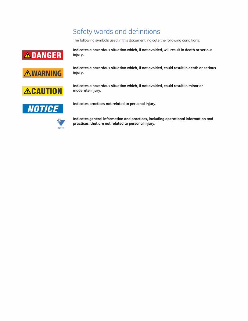
Safety words and definitionsThe following symbols used in this document indicate the following conditions:
Note Indicates a hazardous situation which, if not avoided, will result in death or serious injury.
Note Indicates a hazardous situation which, if not avoided, could result in death or serious injury.
Note Indicates a hazardous situation which, if not avoided, could result in minor or moderate injury.
Note Indicates practices not related to personal injury.
NOTE
Indicates general information and practices, including operational information and practices, that are not related to personal injury.
Table of contents
Table of Contents
1: INTRODUCTION Overview ..................................................................................................................... 1-1Device Features .......................................................................................................................................... 1-1
Specifications ............................................................................................................. 1-2Power Supply ................................................................................................................................................ 1-2Relay Outputs ............................................................................................................................................... 1-2Digital Inputs ................................................................................................................................................ 1-2Sensor Inputs ............................................................................................................................................... 1-2Industrial Test Certification .................................................................................................................... 1-3Environmental Specifications .............................................................................................................. 1-4
2: INSTALLATION Mechanical Installation ............................................................................................ 2-1Case Description ......................................................................................................................................... 2-1Sensor Description ..................................................................................................................................... 2-2
Electrical Installation ................................................................................................ 2-3Wiring Description ..................................................................................................................................... 2-3Terminal Connection Layout ................................................................................................................. 2-4
3: INTERFACE Front Control Panel Interface ................................................................................. 3-1LED Status Indicators ............................................................................................................................... 3-2Pushbutton .................................................................................................................................................... 3-2Slide Switches .............................................................................................................................................. 3-2Rotary Switch ............................................................................................................................................... 3-2
4: PRINCIPLE OF OPERATION
Conditions conducive to arcing events ................................................................. 4-1Working principle and Logic diagram .............................................................................................. 4-2Sensor coverage ......................................................................................................................................... 4-5Auto Calibrations ........................................................................................................................................ 4-5
5: APPLICATION Typical applications .................................................................................................. 5-1Case 1: Application ................................................................................................................................... 5-2Case 2: Current supervision ................................................................................................................. 5-4Case 3: Cascade connection ................................................................................................................. 5-6Case 4: Bus bar coverage with cascade connection ............................................................... 5-8
APPENDIX: Change notes .............................................................................................. Appendix-1Manual Revision history .........................................................................................................Appendix-1

CHAPTER TOC:
TOC–II MULTILIN A60 ARC FLASH SYSTEM – INSTRUCTION MANUAL
Multilin A60 Arc Flash System
Chapter 1: Introduction
GE Digital Energy
Introduction
Overview
The A60 Arc Flash System (AFS) is a stand-alone unit equipped with external sensors to detect an arc flash. The sensors are designed to detect the arc flash using the light and sound waves present during the fault. The detection, from a sensor, is sent via fiber optics to the AFS and drives onboard output relays. To achieve an instantaneous response (approx. 1 ms), a PLD is used in place of the conventional CPU.
Device FeaturesThe A60 Arc Flash System provides the following features.
• Fast arc flash protection using multiple sensorsMultiple sensors, up to 5 per AFS device, can be applied. Each sensor can detect both light and sound from an arc flash event. The arc flash can be detected as quickly as 1 ms.
• Self-supervisionThe sensor and fiber cable between the sensor and the AFS unit is supervised continuously. An LED is used to indicate the health of the sensor and its connection to the AFS unit.
• Current supervisionExternal current supervision from a separate Instantaneous Over Current (IOC) device can be used to enhance the security of the AFS unit.
• Transfer tripThe cascading of various AFS units to pass a trip signal from the farthest AFS unit to the AFS unit connected to the main circuit breaker. With this feature, there is no requirement to extend SSR outputs from all AFS units to the main circuit breaker.
• Local and remote resetThe reset feature is supported locally or remotely.
MULTILIN A60 ARC FLASH SYSTEM – INSTRUCTION MANUAL 1–1
SPECIFICATIONS CHAPTER 1: INTRODUCTION
Specifications
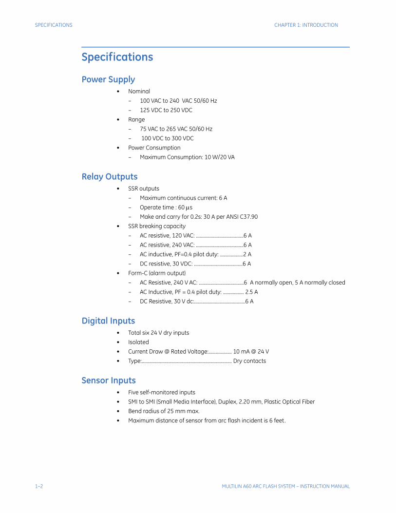
Power Supply• Nominal
– 100 VAC to 240 VAC 50/60 Hz
– 125 VDC to 250 VDC
• Range
– 75 VAC to 265 VAC 50/60 Hz
– 100 VDC to 300 VDC
• Power Consumption
– Maximum Consumption: 10 W/20 VA
Relay Outputs• SSR outputs
– Maximum continuous current: 6 A
– Operate time : 60 s
– Make and carry for 0.2s: 30 A per ANSI C37.90
• SSR breaking capacity
– AC resistive, 120 VAC: .......................................6 A
– AC resistive, 240 VAC: .......................................6 A
– AC inductive, PF=0.4 pilot duty: ...................2 A
– DC resistive, 30 VDC: ........................................6 A
• Form-C (alarm output)
– AC Resistive, 240 V AC: .....................................6 A normally open, 5 A normally closed
– AC Inductive, PF = 0.4 pilot duty: ................. 2.5 A
– DC Resistive, 30 V dc:..........................................6 A
Digital Inputs• Total six 24 V dry inputs
• Isolated
• Current Draw @ Rated Voltage:................... 10 mA @ 24 V
• Type:.......................................................................... Dry contacts
Sensor Inputs• Five self-monitored inputs
• SMI to SMI (Small Media Interface), Duplex, 2.20 mm, Plastic Optical Fiber
• Bend radius of 25 mm max.
• Maximum distance of sensor from arc flash incident is 6 feet.
1–2 MULTILIN A60 ARC FLASH SYSTEM – INSTRUCTION MANUAL
CHAPTER 1: INTRODUCTION SPECIFICATIONS
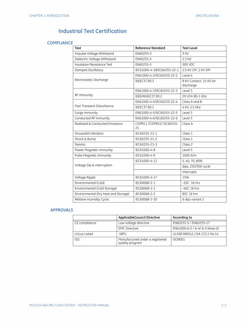
Industrial Test Certification
COMPLIANCE
APPROVALS
Test Reference Standard Test Level
Impulse Voltage Withstand EN60255-5 5 KV
Dielectric Voltage Withstand EN60255-5 2.3 KV
Insulation Resistance Test EN60255-5 500 VDC
Damped Oscillatory IEC61000-4-18IEC60255-22-1 2.5 KV CM, 1 KV DM
Electrostatic Discharge EN61000-4-2/IEC60255-22-2 Level 4
IEEEC37.90.3 8 KV Contact, 15 KV air discharge
RF Immunity EN61000-4-3/IEC60255-22-3 Level 3
IEEE/ANSIC37.90.2 20 V/m 80-1 Ghz
Fast Transient Disturbance EN61000-4-4/IEC60255-22-4 Class A and B
IEEEC37.90.1 4 KV, 2.5 Khz
Surge Immunity EN61000-4-5/IEC60255-22-5 Level 3
Conducted RF Immunity EN61000-4-6/IEC60255-22-6 Level 3
Radiated & Conducted Emissions CISPR11 /CISPR22/ IEC60255-25
Class A
Sinusoidal Vibration IEC60255-21-1 Class 1
Shock & Bump IEC60255-21-2 Class 1
Siesmic IEC60255-21-3 Class 2
Power Magnetic Immunity IEC61000-4-8 Level 5
Pulse Magnetic Immunity IEC61000-4-9 1000 A/m
Voltage Dip & interruption IEC61000-4-11 0, 40, 70, 80%
dips, 250/300 cycle
interrupts
Voltage Ripple IEC61000-4-17 15%
Environmental (Cold) IEC60068-2-1 -20C 16 hrs
Environmental (Cold Storage) IEC60068-2-1 -40C 16 hrs
Environmental (Dry heat and Storage) IEC60068-2-2 85C 16 hrs
Relative Humidity Cyclic IEC60068-2-30 6 day variant 2
ApplicableCouncil Directive According to
CE compliance
Low voltage directive EN60255-5 / EN60255-27
EMC Directive EN61000-6-2 / 6-4/ 6-5 (Area G)
cULus Listed NRTL UL508 (NRGU), CSA C22.2 No.14
ISO Manufactured under a registered quality program
ISO9001
MULTILIN A60 ARC FLASH SYSTEM – INSTRUCTION MANUAL 1–3
SPECIFICATIONS CHAPTER 1: INTRODUCTION
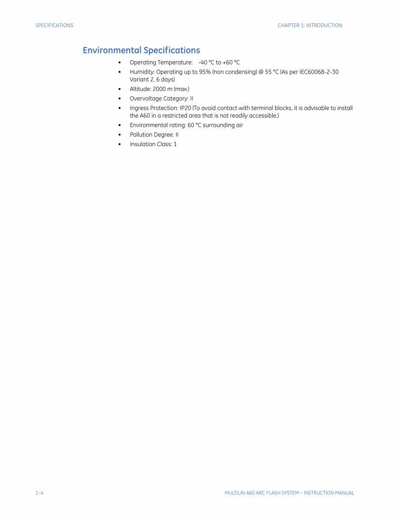
Environmental Specifications • Operating Temperature: -40 °C to +60 °C
• Humidity: Operating up to 95% (non condensing) @ 55 °C (As per IEC60068-2-30 Variant 2, 6 days)
• Altitude: 2000 m (max.)
• Overvoltage Category: II
• Ingress Protection: IP20 (To avoid contact with terminal blocks, it is advisable to install the A60 in a restricted area that is not readily accessible.)
• Environmental rating: 60 °C surrounding air
• Pollution Degree: II
• Insulation Class: 1
1–4 MULTILIN A60 ARC FLASH SYSTEM – INSTRUCTION MANUAL
Multilin A60 Arc Flash System
Chapter 2: Installation
GE Digital Energy
Installation
Mechanical Installation
The AFS should be mounted so that the display indicators and switches are accessible. Mounting of the unit is determined by location, environment and application.
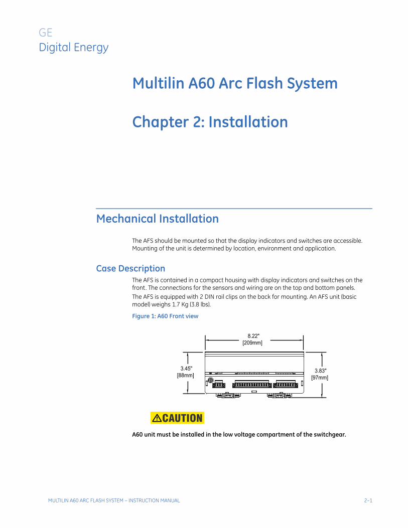
Case DescriptionThe AFS is contained in a compact housing with display indicators and switches on the front. The connections for the sensors and wiring are on the top and bottom panels. The AFS is equipped with 2 DIN rail clips on the back for mounting. An AFS unit (basic model) weighs 1.7 Kg (3.8 lbs).
Figure 1: A60 Front view
A60 unit must be installed in the low voltage compartment of the switchgear.
3.45" [88mm]
3.83" [97mm]
8.22" [209mm]
MULTILIN A60 ARC FLASH SYSTEM – INSTRUCTION MANUAL 2–1
MECHANICAL INSTALLATION CHAPTER 2: INSTALLATION
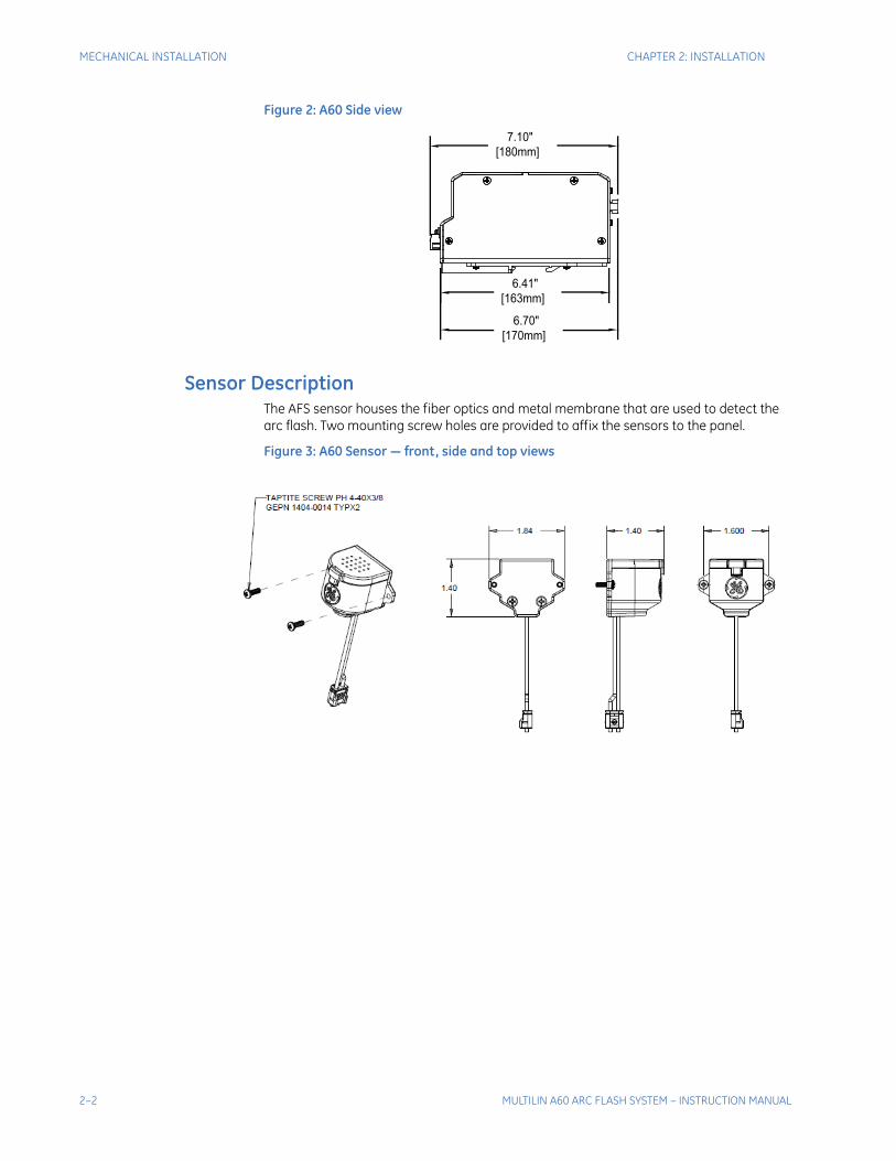
Figure 2: A60 Side view
Sensor DescriptionThe AFS sensor houses the fiber optics and metal membrane that are used to detect the arc flash. Two mounting screw holes are provided to affix the sensors to the panel.
Figure 3: A60 Sensor — front, side and top views
6.70" [170mm]
6.41" [163mm]
7.10" [180mm]
2–2 MULTILIN A60 ARC FLASH SYSTEM – INSTRUCTION MANUAL
CHAPTER 2: INSTALLATION ELECTRICAL INSTALLATION
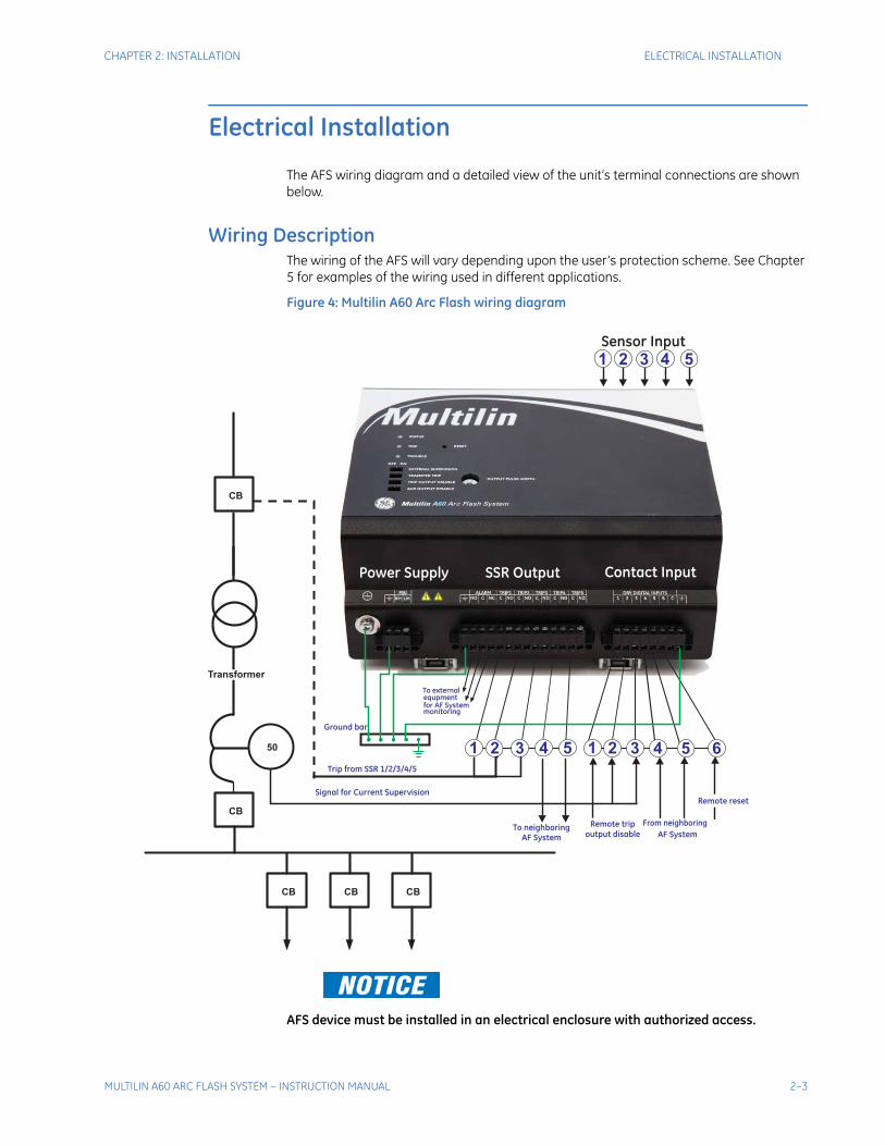
Electrical Installation
The AFS wiring diagram and a detailed view of the unit’s terminal connections are shown below.
Wiring DescriptionThe wiring of the AFS will vary depending upon the user’s protection scheme. See Chapter 5 for examples of the wiring used in different applications.
Figure 4: Multilin A60 Arc Flash wiring diagram
AFS device must be installed in an electrical enclosure with authorized access.
CB
CB CB
CB
Contact Input
50
Transformer
SSR Output
Trip from SSR 1/2/3/4/5
CB
Power Supply
Remote reset
AF System
Remote trip
output disable
Signal for Current Supervision
From neighboring
AF System
541 32 632 41 5
541 32
Sensor Input
Ground bar
To neighboring
To external
for AF Systemmonitoring
equpment
MULTILIN A60 ARC FLASH SYSTEM – INSTRUCTION MANUAL 2–3
ELECTRICAL INSTALLATION CHAPTER 2: INSTALLATION
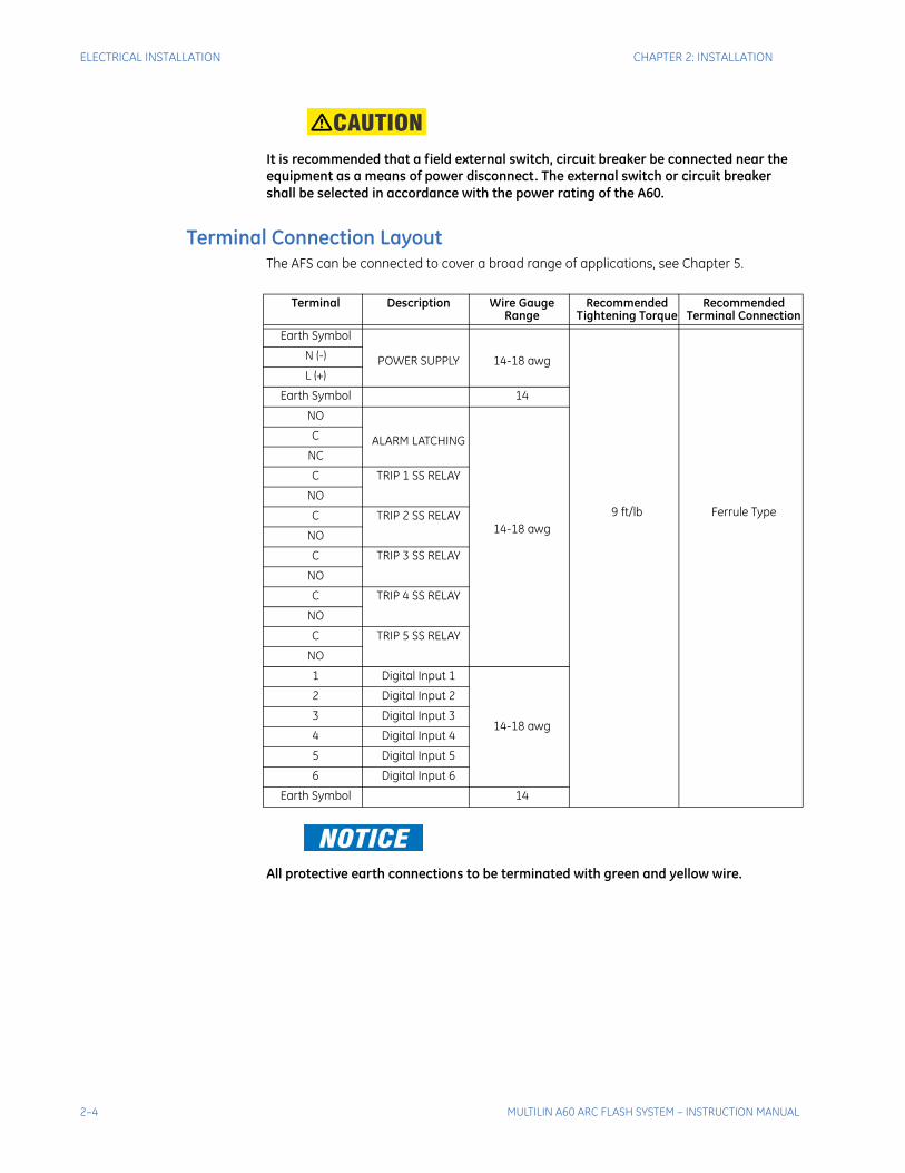
It is recommended that a field external switch, circuit breaker be connected near the equipment as a means of power disconnect. The external switch or circuit breaker shall be selected in accordance with the power rating of the A60.
Terminal Connection LayoutThe AFS can be connected to cover a broad range of applications, see Chapter 5.
All protective earth connections to be terminated with green and yellow wire.
Terminal Description Wire Gauge Range
Recommended Tightening Torque
Recommended Terminal Connection
Earth Symbol
POWER SUPPLY 14-18 awg
9 ft/lb Ferrule Type
N (-)
L (+)
Earth Symbol 14
NO
ALARM LATCHING
14-18 awg
C
NC
C TRIP 1 SS RELAY
NO
C TRIP 2 SS RELAY
NO
C TRIP 3 SS RELAY
NO
C TRIP 4 SS RELAY
NO
C TRIP 5 SS RELAY
NO
1 Digital Input 1
14-18 awg
2 Digital Input 2
3 Digital Input 3
4 Digital Input 4
5 Digital Input 5
6 Digital Input 6
Earth Symbol 14
2–4 MULTILIN A60 ARC FLASH SYSTEM – INSTRUCTION MANUAL
CHAPTER 2: INSTALLATION ELECTRICAL INSTALLATION
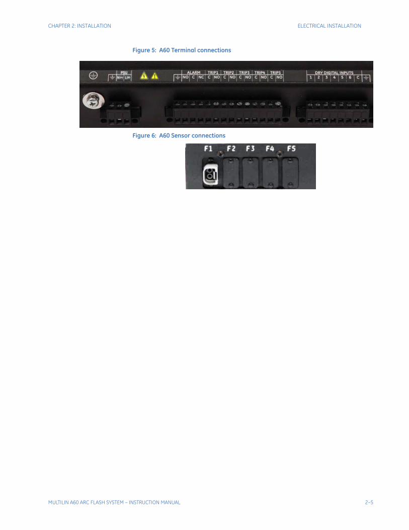
Figure 5: A60 Terminal connections
Figure 6: A60 Sensor connections
MULTILIN A60 ARC FLASH SYSTEM – INSTRUCTION MANUAL 2–5

ELECTRICAL INSTALLATION CHAPTER 2: INSTALLATION
2–6 MULTILIN A60 ARC FLASH SYSTEM – INSTRUCTION MANUAL
Multilin A60 Arc Flash System
Chapter 3: Interface
GE Digital Energy
Interface
Front Control Panel Interface
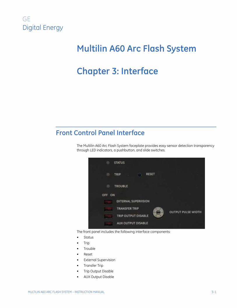
The Multilin A60 Arc Flash System faceplate provides easy sensor detection transparency through LED indicators, a pushbutton, and slide switches.
The front panel includes the following interface components:
• Status
• Trip
• Trouble
• Reset
• External Supervision
• Transfer Trip
• Trip Output Disable
• AUX Output Disable
MULTILIN A60 ARC FLASH SYSTEM – INSTRUCTION MANUAL 3–1
FRONT CONTROL PANEL INTERFACE CHAPTER 3: INTERFACE
LED Status IndicatorsSTATUS
The status LED glows in green during normal in-service-operation mode. The not-in-service mode is represented by a red color indication of the status LED. An orange color indication of this LED shows the calibration mode.
TRIPUpon direct arc-flash detection, or OC supervised AF detection, the trip LED turns on in a red color indicating operation of the arc flash system.
TROUBLEDuring sensor detection any issues (or during no local calibration), the trouble LED turns on in an orange color. Based on the corresponding sensor number, the trouble LED gives blink indication consecutively (i.e., if a fault is detected by sensor # 3, the trouble LED blinks three times).
PushbuttonRESET
This pushbutton resets the states of the Solid State outputs. Pressing the pushbutton creates a pulse for resetting the “TRIP” LEDs and the outputs. Resetting of the LEDs and the outputs can also be done remotely by energizing contact input # 6.
Slide SwitchesEXTERNAL SUPERVISION
When the external supervison slide switch is at the “ON” position the triggering of the Solid State outputs depend on the detection of an arc flash, and the “On” state of any of the two contact inputs: Contact Input # 2 or Contact Input # 3. These contacts may be connected to Solid State output relays from a protective device to indicate overcurrent conditions during the arc flash. When the slide switch is at the “OFF” position, the detection of an arc flash does not depend on external Contact Inputs, and Solid State outputs depend on the detection of the arc-flash sensors.
TRANSFER TRIPThis switch has two positions – “ON” and “OFF”. The switch is set to “ON”, if direct transfer trip is permissible from neighboring AF system(s). Contact inputs 4 and 5 can be wired to SSR output from neighboring AF units. Select “OFF”, if these contact inputs are not used.
TRIP OUTPUT DISABLEThis slide switch is used to enable or disable all Solid State outputs at once. If the switch is set to “ON”, all SSR outputs are disabled and the arc-flash system does not send any SSR outputs. In case of “OFF”, all the SSR outputs are enabled. In addition, SSR (trip) outputs can be disabled/enabled remotely by energizing Contact Input # 1. Therefore, if input signal is received at Contact input # 1, all SSR outputs will be disabled.
AUX OUTPUT DISABLEThe SSR output contacts 4 and 5 are used for transfer trip to adjacent AF systems. Therefore, if the switch is set to “OFF”, both output 4 and 5 are enabled, and result in a send output command/trip in case of arc-flash detection.
Rotary SwitchOUTPUT PULSE WIDTH
The AF unit has a rotary switch for setting the pulse width time of the output trip signals in seconds for outputs 1, 2, 3, 4, 5, and 0. If the rotary switch is set to “0”, the solid-state output will remain energized upon AF scheme operation, after the conditions clear. The states of the outputs are cleared after the “RESET” operation.Note: Pulse width tolerance is +10 ms of setting
3–2 MULTILIN A60 ARC FLASH SYSTEM – INSTRUCTION MANUAL
Multilin A60 Arc Flash System
Chapter 4: Principle of Operation
GE Digital Energy
Principle of Operation
Conditions conducive to arcing events
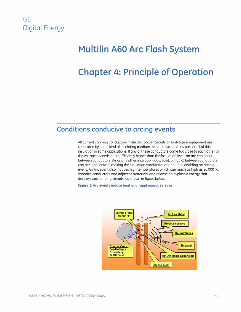
All current carrying conductors in electric power circuits or switchgear equipment are separated by some kind of insulating medium. Air can also serve as part or all of this insulation in some applications. If any of these conductors come too close to each other, or the voltage exceeds or is sufficiently higher than the insulation level, an arc can occur between conductors. Air or any other insulation (gas, solid, or liquid) between conductors can become ionized, making the insulation conductive and thereby enabling an arcing event. An Arc event also induces high temperatures which can reach as high as 20,000 °C, vaporize conductors and adjacent materials, and release an explosive energy that destroys surrounding circuits, as shown in figure below.
Figure 1: Arc events induce heat and rapid energy release
MULTILIN A60 ARC FLASH SYSTEM – INSTRUCTION MANUAL 4–1
CONDITIONS CONDUCIVE TO ARCING EVENTS CHAPTER 4: PRINCIPLE OF OPERATION
Working principle and Logic diagramGE Multilin’s advanced technology solution for Arc Flash (AF) detection logic utilizes two common facts of any arc flash event:
1. intensity of light and sound pressure above the threshold
2. the difference in the speed of light and sound signal detection
NOTE
Note that the threshold values are adaptively calibrated by A60, and hence there is no need for any information for setting up these values. Refer to the self-calibration features in this article for more details. The difference in speed between light (3x10⁸ m/s) and sound (343 m/s) generates a unique time delay signature that may be used to differentiate an arc flash event from other sources of light and sound. Based on these two parameters, A60 first detects the light signal above the threshold value, and then waits for the pressurized sound signal (which should be received within a design specific wait-time value of a few milliseconds). If the pressurized sound signal (within the metal clad switchgear) is received with a higher than threshold value as well as within the design specific wait-time, then the A60 is activated and sends a trip signal. The A60 is immediately reset within the wait-time (a few milliseconds), and again ready for the protection. This logic applies to any of the five individual fiber sensor of the A60, since all the individual optical sensors has its own redundant arc flash detection mechanism, as well as self-check functionality. This provides a higher level of redundancy/reliability of the system. In addition, the A60 also facilitates current supervision (optional), which relies on an external over-current device signal to be received, for the arc flash protection. In addition to the presented light and sound detection, this option provides additional security to the arc flash protection.
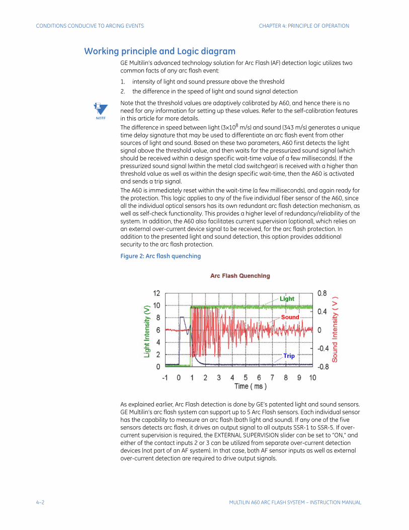
Figure 2: Arc flash quenching
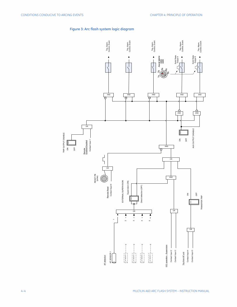
As explained earlier, Arc Flash detection is done by GE’s patented light and sound sensors. GE Multilin’s arc flash system can support up to 5 Arc Flash sensors. Each individual sensor has the capability to measure an arc flash (both light and sound). If any one of the five sensors detects arc flash, it drives an output signal to all outputs SSR-1 to SSR-5. If over-current supervision is required, the EXTERNAL SUPERVISION slider can be set to “ON,” and either of the contact inputs 2 or 3 can be utilized from separate over-current detection devices (not part of an AF system). In that case, both AF sensor inputs as well as external over-current detection are required to drive output signals.
4–2 MULTILIN A60 ARC FLASH SYSTEM – INSTRUCTION MANUAL

CHAPTER 4: PRINCIPLE OF OPERATION CONDITIONS CONDUCIVE TO ARCING EVENTS
Moreover, cascading of GE Multilin’s AF system can be achieved by turning “ON” the TRANSFER TRIP slide switch, which allows either Contact Input #4 or #5 to transfer output trip commands directly. In addition the AUX OUTPUT DISABLE switch allows the user to send outputs-4 and -5 to the upstream AF system, for transfer trip application. The duration for outputs-4 and -5 can be set by a rotary switch for 1 to 5 seconds or infinite duration. All outputs can be disabled during system testing mode using the TRIP OUTPUT DISABLE switch. And, the AF system can be reset after operation, by pressing the RESET pushbutton on the front panel. Further detailed operation of the slide switches and rotary switch are explained in the Interface section.The logic diagram of GE Multilin’s arc flash system is shown in the figure below.
MULTILIN A60 ARC FLASH SYSTEM – INSTRUCTION MANUAL 4–3
CONDITIONS CONDUCIVE TO ARCING EVENTS CHAPTER 4: PRINCIPLE OF OPERATION
Figure 3: Arc flash system logic diagram
Co
nta
ct
Inp
ut
2
Dire
ct
de
tectio
n (
OF
F)
Su
pe
rvis
ion
(O
N)
OR
ON
OF
F
AND
OR
1
2 3 4 5
AND AND AND AND AND
ON
OF
F
So
lid S
tate
Ou
tpu
t 5
AND AND
Trip
fro
mA
F u
nit
Co
nta
ct
Inp
ut
5
TR
AN
SF
ER
TR
IP
1s
2s 3
s
4s
5s
So
lid S
tate
Ou
tpu
t 4
Trip
,A
larm
,
Co
ntr
ol, E
ve
nt
Trip
,A
larm
,
Co
ntr
ol, E
ve
nt
Trip
,A
larm
,
Co
ntr
ol, E
ve
nt
Trip
,A
larm
,
Co
ntr
ol, E
ve
nt
Trip
,A
larm
,
Co
ntr
ol, E
ve
nt
PU
LS
E W
IDT
H
SS
R4
SS
R5
RE
SE
TP
B
(pu
lse
)
OR
Re
mo
te R
ese
t
AF
SE
NS
OR
2
AF
SE
NS
OR
3
AF
SE
NS
OR
4
AF
SE
NS
OR
5
Co
nta
ct
Inp
ut
3AND
OR
Re
mo
te
En
ab
led
/Dis
ab
led
OR
IOC
op
era
tio
n -
Su
pe
rvis
ion
AF
SE
NS
OR
1
OR
Co
nta
ct
Inp
ut
4
Co
nta
ct
Inp
ut
6
AF
de
tectio
n
Co
nta
ct
Inp
ut
1
AU
X O
UT
PU
TD
ISA
BL
E
TR
IPO
UT
PU
TD
ISA
BL
E
ON
OF
F
EX
TE
RN
AL
SU
PE
RV
ISIO
N
4–4 MULTILIN A60 ARC FLASH SYSTEM – INSTRUCTION MANUAL
CHAPTER 4: PRINCIPLE OF OPERATION CONDITIONS CONDUCIVE TO ARCING EVENTS
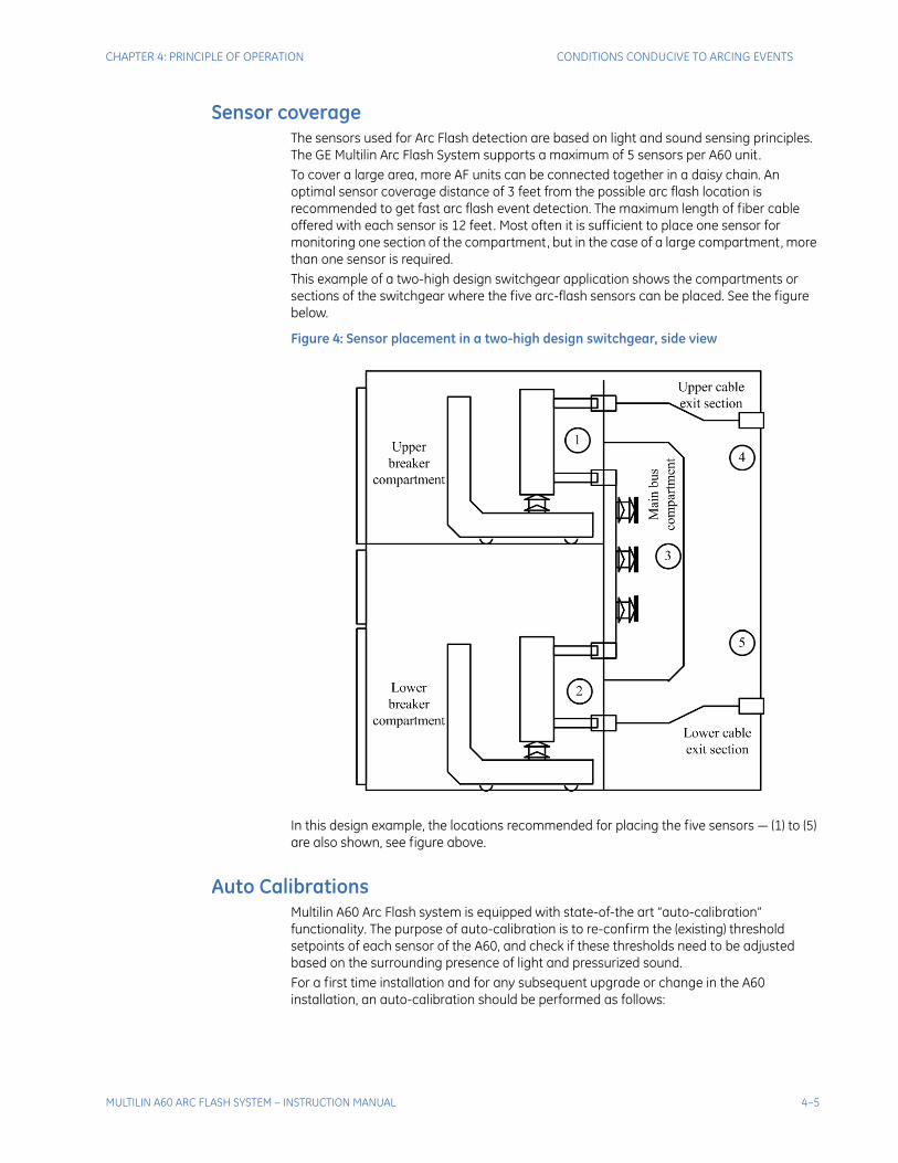
Sensor coverageThe sensors used for Arc Flash detection are based on light and sound sensing principles. The GE Multilin Arc Flash System supports a maximum of 5 sensors per A60 unit. To cover a large area, more AF units can be connected together in a daisy chain. An optimal sensor coverage distance of 3 feet from the possible arc flash location is recommended to get fast arc flash event detection. The maximum length of fiber cable offered with each sensor is 12 feet. Most often it is sufficient to place one sensor for monitoring one section of the compartment, but in the case of a large compartment, more than one sensor is required.This example of a two-high design switchgear application shows the compartments or sections of the switchgear where the five arc-flash sensors can be placed. See the figure below.
Figure 4: Sensor placement in a two-high design switchgear, side view
In this design example, the locations recommended for placing the five sensors — (1) to (5) are also shown, see figure above.
Auto CalibrationsMultilin A60 Arc Flash system is equipped with state-of-the art “auto-calibration” functionality. The purpose of auto-calibration is to re-confirm the (existing) threshold setpoints of each sensor of the A60, and check if these thresholds need to be adjusted based on the surrounding presence of light and pressurized sound.For a first time installation and for any subsequent upgrade or change in the A60 installation, an auto-calibration should be performed as follows:
MULTILIN A60 ARC FLASH SYSTEM – INSTRUCTION MANUAL 4–5
CONDITIONS CONDUCIVE TO ARCING EVENTS CHAPTER 4: PRINCIPLE OF OPERATION
1. Complete the “Mechanical and Electrical installation” of the Arc Flash device as demonstrated in Chapter 2, as well as “sensor installations” per the recommended guidelines explained in the previous section.
2. Once the installation is finished, press “Reset” for few seconds, until the STATUS LED starts blinking an orange color. This shows that the A60 system is successfully starting the auto-calibration.
NOTE
NOTE: Make sure that the A60 system (which includes the device sensors) is not exposed to arc during this auto-calibration mode. If it is, repeat the process again without arc.
3. The A60 system performs auto-calibration of each sensor in sequence, and adaptively sets individual threshold values. This process may take few minutes to finish. The device automatically performs the calibration.
4. Once A60 completes the auto-calibration process, the STATUS LED automatically changes from a blinking orange light to a steady green light, which represents the normal operation mode of the device.
NOTE
NOTE: We recommend performing the auto-calibration steps for any change in installation, such as a change in location OR a change in any component of A60 (i.e. sensor, fiber cable, etc.).
4–6 MULTILIN A60 ARC FLASH SYSTEM – INSTRUCTION MANUAL
Multilin A60 Arc Flash System
Chapter 5: Application
GE Digital Energy
Application
Typical applications
This section provides several examples, for the purpose of illustration, of the Multilin Arc Flash System (AFS) usage and the corresponding front panel switch settings.In the following, the first case describes a one unit setup. Case 2 includes the supervision capability. The next two cases describe setups with multiple AFS units.
MULTILIN A60 ARC FLASH SYSTEM – INSTRUCTION MANUAL 5–1
TYPICAL APPLICATIONS CHAPTER 5: APPLICATION
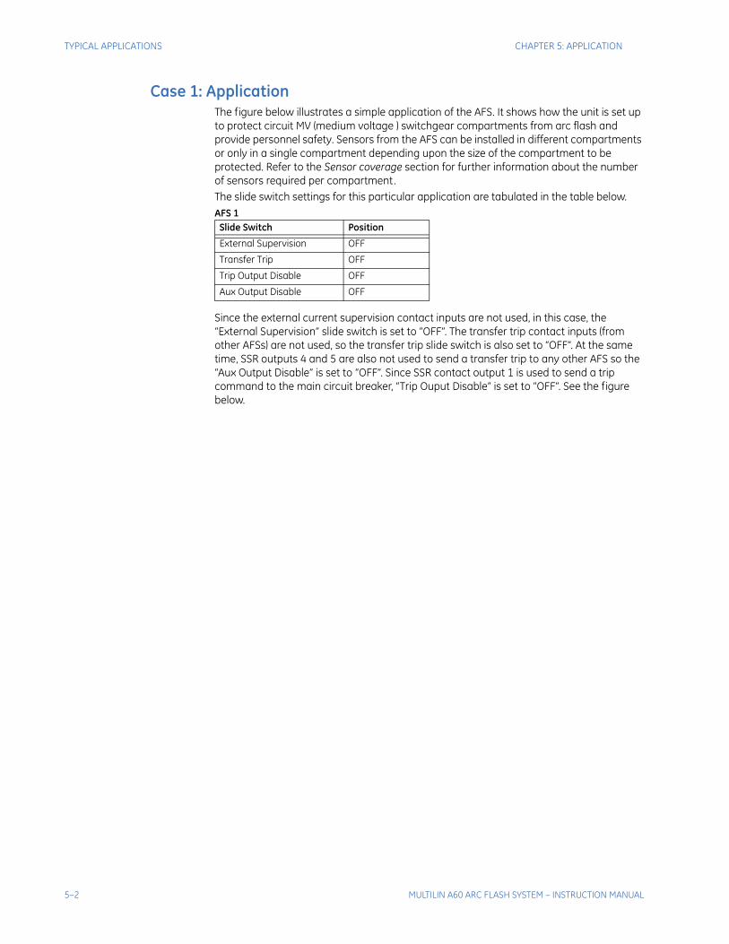
Case 1: Application The figure below illustrates a simple application of the AFS. It shows how the unit is set up to protect circuit MV (medium voltage ) switchgear compartments from arc flash and provide personnel safety. Sensors from the AFS can be installed in different compartments or only in a single compartment depending upon the size of the compartment to be protected. Refer to the Sensor coverage section for further information about the number of sensors required per compartment.The slide switch settings for this particular application are tabulated in the table below. AFS 1
Since the external current supervision contact inputs are not used, in this case, the “External Supervision” slide switch is set to “OFF”. The transfer trip contact inputs (from other AFSs) are not used, so the transfer trip slide switch is also set to “OFF”. At the same time, SSR outputs 4 and 5 are also not used to send a transfer trip to any other AFS so the “Aux Output Disable” is set to “OFF”. Since SSR contact output 1 is used to send a trip command to the main circuit breaker, “Trip Ouput Disable” is set to “OFF”. See the figure below.
Slide Switch Position
External Supervision OFF
Transfer Trip OFF
Trip Output Disable OFF
Aux Output Disable OFF
5–2 MULTILIN A60 ARC FLASH SYSTEM – INSTRUCTION MANUAL
CHAPTER 5: APPLICATION TYPICAL APPLICATIONS
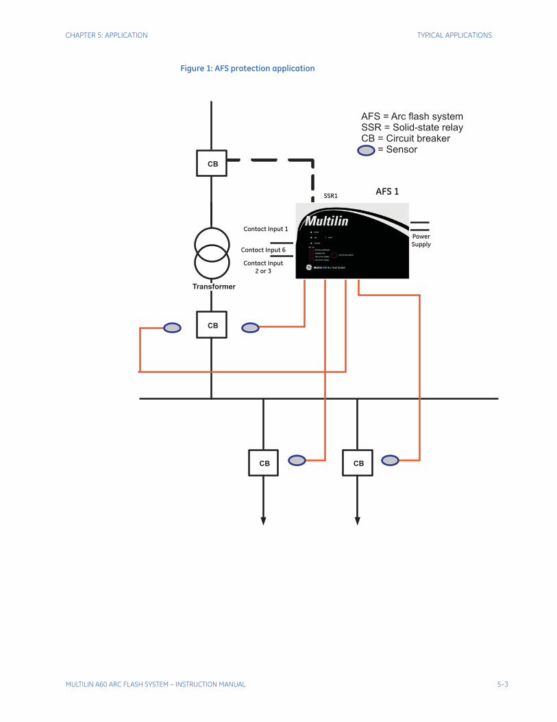
Figure 1: AFS protection application
CB
CB
CB CB
SSR 1
Contact Input
2 or 3
Contact Input 1
Contact Input 6
Power
Supply
SSR1
Transformer
AFS = Arc flash systemSSR = Solid-state relayCB = Circuit breaker
= Sensor
AFS 1
MULTILIN A60 ARC FLASH SYSTEM – INSTRUCTION MANUAL 5–3
TYPICAL APPLICATIONS CHAPTER 5: APPLICATION
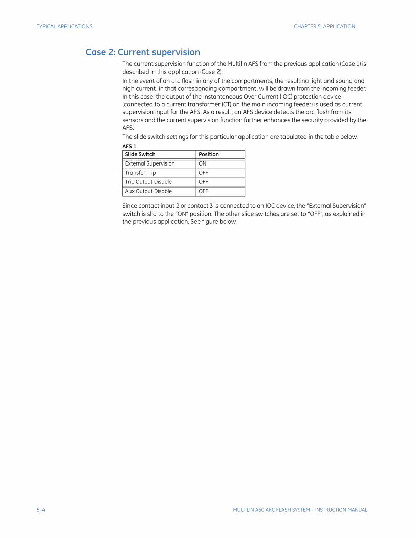
Case 2: Current supervision The current supervision function of the Multilin AFS from the previous application (Case 1) is described in this application (Case 2).In the event of an arc flash in any of the compartments, the resulting light and sound and high current, in that corresponding compartment, will be drawn from the incoming feeder. In this case, the output of the Instantaneous Over Current (IOC) protection device (connected to a current transformer (CT) on the main incoming feeder) is used as current supervision input for the AFS. As a result, an AFS device detects the arc flash from its sensors and the current supervision function further enhances the security provided by the AFS.The slide switch settings for this particular application are tabulated in the table below.AFS 1
Since contact input 2 or contact 3 is connected to an IOC device, the “External Supervision” switch is slid to the “ON” position. The other slide switches are set to “OFF”, as explained in the previous application. See figure below.
Slide Switch Position
External Supervision ON
Transfer Trip OFF
Trip Output Disable OFF
Aux Output Disable OFF
5–4 MULTILIN A60 ARC FLASH SYSTEM – INSTRUCTION MANUAL
CHAPTER 5: APPLICATION TYPICAL APPLICATIONS
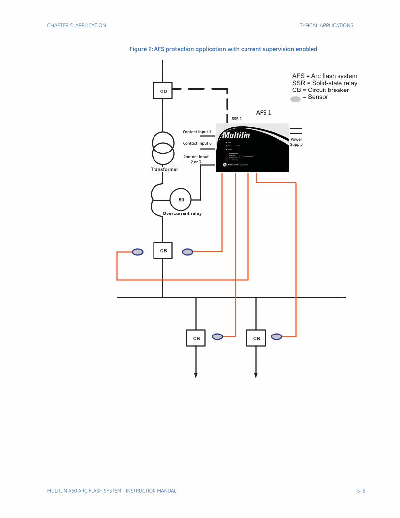
Figure 2: AFS protection application with current supervision enabled
CB
CB CB
CB
SSR 1
Contact Input
2 or 3
Contact Input 1
Contact Input 6
Power
Supply
50
AFS = Arc flash systemSSR = Solid-state relayCB = Circuit breaker
= Sensor
Overcurrent relay
Transformer
AFS 1
MULTILIN A60 ARC FLASH SYSTEM – INSTRUCTION MANUAL 5–5
TYPICAL APPLICATIONS CHAPTER 5: APPLICATION
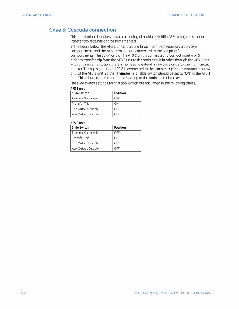
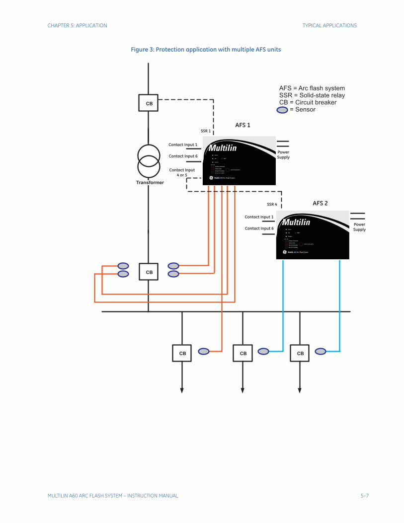
Case 3: Cascade connectionThis application describes how a cascading of multiple Multilin AFSs using the support transfer trip features can be implemented. In the figure below, the AFS 1 unit protects a large incoming feeder circuit breaker compartment, and the AFS 2 sensors are connected to the outgoing feeder’s compartments. The SSR 4 or 5 of the AFS 2 unit is connected to contact input 4 or 5 in order to transfer trip from the AFS 2 unit to the main circuit breaker through the AFS 1 unit. With this implementation, there is no need to extend many trip signals to the main circuit breaker. The trip signal from AFS 2 is connected to the transfer trip inputs (contact inputs 4 or 5) of the AFS 1 unit, so the “Transfer Trip” slide switch should be set to “ON” in the AFS 1 unit. This allows transferral of the AFS 2 trip to the main circuit breaker. The slide switch settings for this application are tabulated in the following tables.AFS 1 unit
AFS 2 unit
Slide Switch Position
External Supervision OFF
Transfer Trip ON
Trip Output Disable OFF
Aux Output Disable OFF
Slide Switch Position
External Supervision OFF
Transfer Trip OFF
Trip Output Disable OFF
Aux Output Disable OFF
5–6 MULTILIN A60 ARC FLASH SYSTEM – INSTRUCTION MANUAL
CHAPTER 5: APPLICATION TYPICAL APPLICATIONS
Figure 3: Protection application with multiple AFS units
CB CB
CB
SSR 1
Contact Input
4 or 5
Contact Input 1
Contact Input 6
Power
Supply
CB
CB
SSR 4
Contact Input 1
Contact Input 6
Power
Supply
AFS 1
AFS 2
AFS = Arc flash systemSSR = Solid-state relayCB = Circuit breaker
= Sensor
Transformer
MULTILIN A60 ARC FLASH SYSTEM – INSTRUCTION MANUAL 5–7
TYPICAL APPLICATIONS CHAPTER 5: APPLICATION
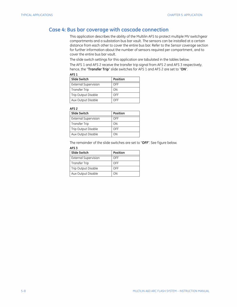
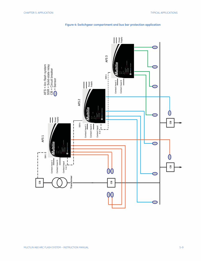
Case 4: Bus bar coverage with cascade connection This application describes the ability of the Multilin AFS to protect multiple MV switchgear compartments and a substation bus bar vault. The sensors can be installed at a certain distance from each other to cover the entire bus bar. Refer to the Sensor coverage section for further information about the number of sensors required per compartment, and to cover the entire bus bar vault.The slide switch settings for this application are tabulated in the tables below.The AFS 1 and AFS 2 receive the transfer trip signal from AFS 2 and AFS 3 respectively, hence, the “Transfer Trip” slide switches for AFS 1 and AFS 2 are set to “ON”.AFS 1
AFS 2
The remainder of the slide switches are set to “OFF”. See figure below.AFS 3
Slide Switch Position
External Supervision OFF
Transfer Trip ON
Trip Output Disable OFF
Aux Output Disable OFF
Slide Switch Position
External Supervision OFF
Transfer Trip ON
Trip Output Disable OFF
Aux Output Disable ON
Slide Switch Position
External Supervision OFF
Transfer Trip OFF
Trip Output Disable OFF
Aux Output Disable ON
5–8 MULTILIN A60 ARC FLASH SYSTEM – INSTRUCTION MANUAL
CHAPTER 5: APPLICATION TYPICAL APPLICATIONS
Figure 4: Switchgear compartment and bus bar protection application
CB
CB
CB
AF
S=
Arc
fla
sh
syste
mS
SR
=S
olid
-sta
tere
lay
CB
=C
ircu
itb
rea
ke
r=
Se
nso
r
CB
SS
R4
Co
nta
ct
Inp
ut
1
Co
nta
ct
Inp
ut
6
Po
we
r
Su
pp
ly
AF
S3
SS
R4
Co
nta
ct
Inp
ut
1
Co
nta
ct
Inp
ut
6
Po
we
r
Su
pp
ly
AF
S2
Co
nta
ct
Inp
ut
4o
r5
Co
nta
ct
Inp
ut
4o
r5
SS
R1
Co
nta
ct
Inp
ut
1
Co
nta
ct
Inp
ut
6
Po
we
r
Su
pp
ly
AF
S1
Tran
sfo
rm
er
MULTILIN A60 ARC FLASH SYSTEM – INSTRUCTION MANUAL 5–9

TYPICAL APPLICATIONS CHAPTER 5: APPLICATION
5–10 MULTILIN A60 ARC FLASH SYSTEM – INSTRUCTION MANUAL
Multilin A60 Arc Flash System
Chapter Appendix:
GE Digital Energy
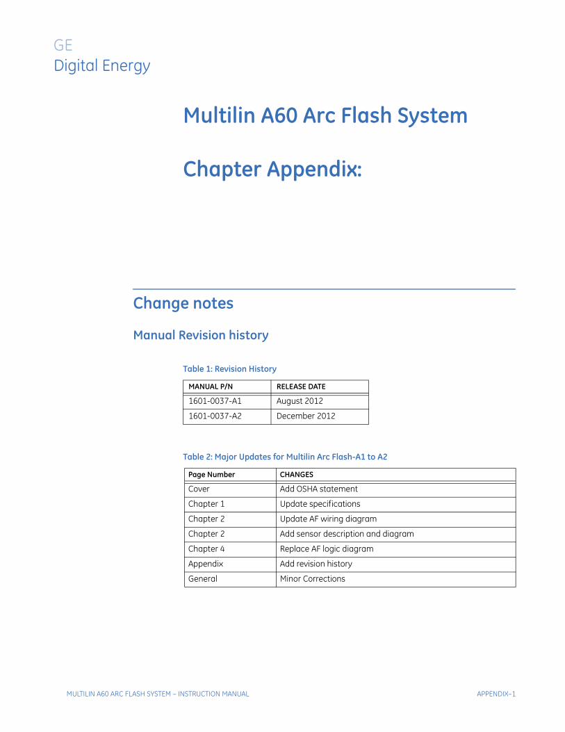
Change notes
Manual Revision history
Table 1: Revision History
MANUAL P/N RELEASE DATE
1601-0037-A1 August 2012
1601-0037-A2 December 2012
Table 2: Major Updates for Multilin Arc Flash-A1 to A2
Page Number CHANGES
Cover Add OSHA statement
Chapter 1 Update specifications
Chapter 2 Update AF wiring diagram
Chapter 2 Add sensor description and diagram
Chapter 4 Replace AF logic diagram
Appendix Add revision history
General Minor Corrections
MULTILIN A60 ARC FLASH SYSTEM – INSTRUCTION MANUAL APPENDIX–1

CHANGE NOTES CHAPTER APPENDIX:
APPENDIX–2 MULTILIN A60 ARC FLASH SYSTEM – INSTRUCTION MANUAL