ge fanuc automation - i-logic server.pdf · ge fanuc automation assumes ... alarm screen appears on...
TRANSCRIPT

GE Fanuc Automation
Computer Numerical Control Products
Data ServerOperator's ManualGFZ-62694EN/03 April 2000
GFL-001
Warnings, Cautions, and Notesas Used in this Publication
Warning
Warning notices are used in this publication to emphasize that hazardous voltages, currents,temperatures, or other conditions that could cause personal injury exist in this equipment ormay be associated with its use.
In situations where inattention could cause either personal injury or damage to equipment, aWarning notice is used.
Caution
Caution notices are used where equipment might be damaged if care is not taken.
NoteNotes merely call attention to information that is especially significant to understanding andoperating the equipment.
This document is based on information available at the time of its publication. While effortshave been made to be accurate, the information contained herein does not purport to cover alldetails or variations in hardware or software, nor to provide for every possible contingency inconnection with installation, operation, or maintenance. Features may be described hereinwhich are not present in all hardware and software systems. GE Fanuc Automation assumesno obligation of notice to holders of this document with respect to changes subsequently made.
GE Fanuc Automation makes no representation or warranty, expressed, implied, or statutorywith respect to, and assumes no responsibility for the accuracy, completeness, sufficiency, orusefulness of the information contained herein. No warranties of merchantability or fitness forpurpose shall apply.
©Copyright 2002 GE Fanuc Automation North America, Inc.
All Rights Reserved.

B-62694EN/03 SAFETY PRECAUTIONS
S-1
This section describes the safety precautions relating to the use of CNC units, toensure safe operation of machines fitted with FANUC CNC units. Read thissection carefully before attempting to use any function described in this manual.Users should also read the relevant descriptions in the Operator's Manual tobecome fully familiar with the functions to be used.
Contents
1. WARNING, CAUTION, AND NOTE ・・・・・・・・・・・・・・・・・・・・・・・・・・・・・ s-22. GENEREAL WARNINGS AND NOTES ・・・・・・・・・・・・・・・・・・・・・・・・・・ s-3
SAFETY PRECAUTIONS
SAFETY PRECAUTIONS B-62694EN/03
S-2
1 WARNING, CAUTION, AND NOTE
This manual includes safety precautions for protecting the user andpreventing damage to the machine. Precautions are classified intoWarning and Caution according to their bearing on safety. Also,supplementary information is described as a Note. Read theWarning, Caution, and Note thoroughly before attempting to use themachine.
WARNINGApplied when there is a danger of the user being injured orwhen there is a damage of both the user being injured andthe equipment being damaged if the approved procedure isnot observed.
CAUTIONApplied when there is a danger of the equipment beingdamaged, if the approved procedure is not observed.
NOTEThe Note is used to indicate supplementary informationother than Warning and Caution.
B-62694EN/03 SAFETY PRECAUTIONS
S-3
2 GENERAL WARNINGS AND NOTES
WARNING1. Before operating the machine, thoroughly check the
entered data.Operating the machine with incorrect data may result in themachine behaving unexpectedly, possibly causing damageto the workpiece and/or machine itself, or injury to the user.
2. Never attempt to perform a production run, such asactually machining a workpiece, without first checking theoperation of the machine. Before starting the machine fora production run, ensure that the program commandvalues, offsets, current position, external signals, and othersettings are suitable for the operation to be performed.Also check that the machine operates correctly byperforming a trial run using, for example, the single block,feedrate override, or machine lock function or by operatingthe machine with neither a tool nor workpiece mounted.
3. Ensure that the specified feedrate is appropriate for theintended operation. Generally, for each machine, there isa maximum allowable feedrate. But, the appropriatefeedrate varies with the intended operation. Refer to themanual provided with the machine to determine themaximum allowable feedrate. If a machine is run at otherthan the correct speed, it may behave unexpectedly,possibly causing damage to the workpiece and/or machineitself, or injury to the user.
4. When using a tool compensation function, thoroughlycheck the direction and amount of compensation.Operating the machine with incorrectly specified data mayresult in the machine behaving unexpectedly, possiblycausing damage to the workpiece and/or machine itself, orinjury to the user.
5. The parameters for the CNC and PMC are factory-set.Usually, there is not need to change them. When,however, there is not alternative other than to change aparameter, ensure that you fully understand the function ofthe parameter before making any change.Failure to set a parameter correctly may result in themachine behaving unexpectedly, possibly causing damageto the workpiece and/or machine itself, or injury to the user.

SAFETY PRECAUTIONS B-62694EN/03
S-4
WARNING6. Immediately after switching on the power, do not touch any
of the keys on the MDI panel until the position display oralarm screen appears on the CNC unit.Some of the keys on the MDI panel are dedicated tomaintenance or other special operations. Pressing any ofthese keys may cause the machine to behaveunexpectedly.
7. The operator's manual supplied with a CNC unit provide anoverall description of the machine's functions, includingany optional functions. Note that the optional functionswill vary from one machine model to another. Therefore,some functions described in the manuals may not actuallybe available for a particular model. Check thespecification of the machine if in doubt.
8. Some machine operations and screen functions mayhave been implemented at the request of the machine-tool builder. When using such functions, refer to themanual supplied by the machine-tool builder for details oftheir use and any related cautions.
NOTE1. Command programs, parameters, and variables are stored
in nonvolatile memory in the CNC unit. Usually, they areretained even if the power is turned off. Such data maybe deleted inadvertently, however, or it may provenecessary to delete all data from nonvolatile memory aspart of error recovery.To guard against the occurrence of the above, and assurequick restoration of deleted data, backup all vital data, andkeep the backup copy in a safe place.

B-62684EN/03 Table of ContentsSAFETY PRECAUTIONS
I. GENERAL
1. OUTLINE.........................................................................................................................................3
II. CONNECTION
1. FOR Series 16/18-B/C, Series 15-B................................................................................................ 91.1 CONSTRUCTION.................................................................................................................................10
1.2 INSTALLATION...................................................................................................................................11
1.2.1 Environmental Requirements.....................................................................................................11
1.2.2 Cable Lead-in Diagram..............................................................................................................12
1.2.3 Connector Disposition of Data Server board .............................................................................13
1.3 GENERAL CONNECTION DIAGRAM ..............................................................................................14
2. FOR Series 16i/18i-A.................................................................................................................... 152.1 CONSTRUCTION.................................................................................................................................16
2.2 INSTALLATION...................................................................................................................................17
2.2.1 Environmental Requirements.....................................................................................................17
2.2.2 Cable Lead-in Diagram..............................................................................................................18
2.2.3 Connector Disposition of Data Server board .............................................................................19
2.3 GENERAL CONNECTION DIAGRAM ..............................................................................................21
2.3.1 General Connection Diagram.....................................................................................................21
2.3.2 Connection of HDD Unit ...........................................................................................................22
3. CONNECTION WITH NETWORK..............................................................................................243.1 CONNECTION WITH THE ETHERNET............................................................................................25
3.2 AUI(Attachment Unit Interface) PIN CONFIGURATION ...................................................................26
3.3 CONNECTION OF THE TRANCEIVER CABLE...............................................................................27
3.4 SHIELDING EARTH OF THE TRANSCEIVER CABLE ...................................................................28
III. MAINTENANCE
1. FOR Series 16/18-B/C, Series 15-B...............................................................................................331.1 SYSTEM BLOCK DIAGRAM..............................................................................................................34
1.2 PARTS LAYOUT..................................................................................................................................35
1.3 LIGHTING OF LEDS AND MEANING ..............................................................................................36

Table of Contents B-62694EN/03
C-2
1.4 HOW TO EXCHANGE A FUSE ..........................................................................................................38
2. FOR Series 16i/18i-A.....................................................................................................................392.1 SYSTEM BLOCK DIAGRAM..............................................................................................................40
2.2 PARTS LAYOUT..................................................................................................................................41
2.3 LIGHTING OF LED AND MEANING................................................................................................. 43
2.3.1 In case of edition 01A................................................................................................................44
2.3.2 In case of latter edition than 02B ...............................................................................................46
IV. OPERATION
1. FOR Series 16/18-B/C, Series 16i/18i-A .......................................................................................511.1 OUTLINE ..............................................................................................................................................52
1.1.1 Notice when you use for the first time .......................................................................................53
1.2 SETTING SCREEN...............................................................................................................................54
1.2.1 Description of each data ............................................................................................................56
1.2.2 How to input data.......................................................................................................................58
1.2.3 How to input small letters ..........................................................................................................60
1.2.4 How to set a Host Directory.......................................................................................................61
1.2.5 How to save modified data ........................................................................................................63
1.3 NC PROGRAM MANAGEMENT FUNCTION...................................................................................64
1.3.1 Displaying the table of NC programs.........................................................................................65
1.3.2 Searching a NC program............................................................................................................69
1.3.3 Deleting NC programs ...............................................................................................................70
1.3.4 Getting a NC program................................................................................................................72
1.3.5 Putting a NC program................................................................................................................74
1.3.6 List-Getting NC programs .........................................................................................................77
1.3.7 List-Putting NC programs..........................................................................................................80
1.3.8 List-Deleting NC programs........................................................................................................83
1.3.9 A format of List-File ..................................................................................................................85
1.3.10 A format of NC program............................................................................................................86
1.4 CALLING A SUBPROGRAM WITH M198 ........................................................................................87
1.5 REGISTERING A NC PROGRAM.......................................................................................................89
1.6 OUTPUTTING A NC PROGRAM .......................................................................................................90
1.7 DNC OPERATION................................................................................................................................91
1.8 MAINTENANCE OF THE BUILT-IN HARD DISK...........................................................................92
1.8.1 Checking the built-in hard disk..................................................................................................92

B-62684EN/03 Table of Contents
C-3
1.8.2 Formatting the built-in hard disk................................................................................................93
1.9 MAINTENANCE OF DATA SERVER ................................................................................................94
1.10 BUFFER MODE (OPTIONAL FUNCTION) .......................................................................................96
1.10.1 How to change the mode............................................................................................................97
1.10.2 How to use the buffer mode.......................................................................................................99
1.10.3 How to divide a large NC program..........................................................................................101
1.11 ERROR MESSAGE.............................................................................................................................103
1.12 PARAMETERS ...................................................................................................................................105
2. FOR Series 15-B ..........................................................................................................................1082.1 OUTLINE ............................................................................................................................................109
2.1.1 Notice when you use for the first time .....................................................................................110
2.2 SETTING SCREEN.............................................................................................................................111
2.2.1 Description of each data ..........................................................................................................113
2.2.2 How to input data.....................................................................................................................115
2.2.3 How to input small letters ........................................................................................................117
2.2.4 How to save modified data ......................................................................................................118
2.3 NC PROGRAM MANAGEMENT FUNCTION.................................................................................119
2.3.1 Displaying the table of NC programs.......................................................................................120
2.3.2 Searching a NC program..........................................................................................................124
2.3.3 Deleting NC programs .............................................................................................................125
2.3.4 Getting a NC program..............................................................................................................127
2.3.5 Putting a NC program..............................................................................................................129
2.3.6 A format of NC program..........................................................................................................131
2.4 CALLING A SUBPROGRAM WITH M198 ......................................................................................132
2.5 REGISTERING A NC PROGRAM.....................................................................................................134
2.6 OUTPUTTING A NC PROGRAM .....................................................................................................136
2.7 DNC OPERATION..............................................................................................................................137
2.8 MAINTENANCE OF THE BUILT-IN HARD DISK.........................................................................138
2.8.1 Checking the built-in hard disk................................................................................................139
2.8.2 Formatting the built-in hard disk..............................................................................................139
2.9 MAINTENANCE OF DATA SERVER ..............................................................................................140
2.10 BUFFER MODE (OPTIONAL FUNCTION) .....................................................................................142
2.10.1 How to change the mode..........................................................................................................143
2.10.2 How to use the buffer mode.....................................................................................................145
2.10.3 How to divide a large NC program..........................................................................................147
2.11 ERROR MESSAGE.............................................................................................................................149

Table of Contents B-62694EN/03
C-4
2.12 PARAMETERS ...................................................................................................................................151
2.13 ALARMS .............................................................................................................................................154
APPENDIX
A. TABLE OF ERROR MESSAGES..............................................................................................157
B. SERIOUS ERROR ......................................................................................................................167B.1 THE IMAGE OF SCREEN .................................................................................................................168
B.2 THE CONTENTS OF SCREEN..........................................................................................................169
C. ETHERNET TECHNICAL TERMS...........................................................................................171
D. ASCII CODE...............................................................................................................................175

I. GENERAL
B-62694EN/03 GENERAL 1. OUTLINE
- 1 -
1 OUTLINE
This manual consists of the following parts:
About this manual SAFETY PRECAUTIONSNotes for reading this manual is described.
I. GENERALChapter organization, applicable models, and relatedmanuals are described.
II. CONNECTIONThe method of connecting each device and notes forconnection are described.
III. MAINTENANCEThe drawing number of the Data Server, meaning of theLEDs, and the error messages are described.
IV. OPERATIONHow to operate the Data Server functions are described.
APPENDIXThe error messages and technical terms, etc. are described.

1. OUTLINE GENERAL B-62694EN/03
- 2 -
Applicable models This manual describes the following models. Each model maybe referred to using an abbreviation, as listed below.
Product NameProduct NameProduct NameProduct Name AbbreviationsAbbreviationsAbbreviationsAbbreviationsFANUC Series 16-TB 16-TBFANUC Series 16-MB 16-MBFANUC Series 16-PB 16-PBFANUC Series 16-LB 16-LBFANUC Series 160-TB 160-TBFANUC Series 160-MB 160-MBFANUC Series 160-PB 160-PBFANUC Series 18-TB 18-TBFANUC Series 18-MB 18-MBFANUC Series 18-PB 18-PBFANUC Series 180-TB 180-TBFANUC Series 180-MB 180-MBFANUC Series 180-PB 180-PBFANUC Series 16-TC 16-TCFANUC Series 16-MC 16-MCFANUC Series 16-PC 16-PCFANUC Series 160-TC 160-TCFANUC Series 160-MC 160-MCFANUC Series 160-PC 160-PCFANUC Series 18-TC 18-TCFANUC Series 18-MC 18-MCFANUC Series 18-PC 18-PCFANUC Series 180-TC 180-TCFANUC Series 180-MC 180-MCFANUC Series 180-PC 180-PCFANUC Series 16i-TA 16i-TAFANUC Series 16i-MA 16i-MAFANUC Series 16i-PA 16i-PAFANUC Series 18i-TA 18i-TAFANUC Series 18i-MA 18i-MAFANUC Series 18i-PA 18i-PA
FANUC Series 15-TB 15-TBFANUC Series 15-MB 15-MB
Series 15-B

B-62694EN/03 GENERAL 1. OUTLINE
- 3 -
Related manuals The manuals related to each model are as follows. Whenreading this manual, also refer to the following manuals asrequired.
Related manual for Series 16/18/160/180-TB/MBManual NameManual NameManual NameManual Name SpecificationSpecificationSpecificationSpecification
NumberNumberNumberNumberDESCRIPTIONS B-62442ECONNECTION MANUAL (HARDWARE)
B-62443E
CONNECTION MANUAL (FUNCTION) B-62443E-1OPERATOR’S MANUAL (FOR LATHE) B-62444EOPERATOR’S MANUAL (FOR MACHINING CENTER)
B-62454E
MAINTENANCE MANUAL B-62445EPARAMETER MANUAL B-62450E
Related manual for Series 16/18/160/180-PBManual NameManual NameManual NameManual Name SpecificationSpecificationSpecificationSpecification
NumberNumberNumberNumberDESCRIPTIONS B-62622ENCONNECTION MANUAL (HARDWARE)
B-62443E
CONNECTION MANUAL (FUNCTION) B-62443E-1CONNECTION MANUAL[Supplement for 16/18/160/180-PB]
B-62623EN
OPERATOR’S MANUAL B-62624ENMAINTENANCE MANUAL B62445EPARAMETER MANUAL B-62450EPARAMETER MANUAL[Supplement for 16/18/160/180-PB]
B-62630EN

1. OUTLINE GENERAL B-62694EN/03
- 4 -
Related manual for Series 16-LBManual NameManual NameManual NameManual Name SpecificationSpecificationSpecificationSpecification
NumberNumberNumberNumberDESCRIPTIONS B-62442CONNECTION MANUAL (HARDWARE)
B-62443
CONNECTION MANUAL (FUNCTION) B-62443-1CONNECTION MANUAL[Supplement for 16-LB]
B-62593EN
OPERATOR’S MANUAL B-62594ENMAINTENANCE MANUAL B62595ENPARAMETER MANUAL B-62450PARAMETER MANUAL[Supplement for 16-LB]
B-62600EN
Related manual for Series 16/18/160/180-TC/MCManual NameManual NameManual NameManual Name SpecificationSpecificationSpecificationSpecification
NumberNumberNumberNumberDESCRIPTIONS B-62752ENCONNECTION MANUAL (HARDWARE)
B-62753EN
CONNECTION MANUAL (FUNCTION) B-62753EN-1OPERATOR’S MANUAL (FOR LATHE) B-62754ENOPERATOR’S MANUAL (FOR MACHINING CENTER)
B-62764EN
MAINTENANCE MANUAL B-62755ENPARAMETER MANUAL B-62760EN
Related manual for Series 16/18/160/180-PCManual NameManual NameManual NameManual Name SpecificationSpecificationSpecificationSpecification
NumberNumberNumberNumberDESCRIPTIONS B-62772ENCONNECTION MANUAL (HARDWARE)
B-62753EN
CONNECTION MANUAL (FUNCTION) B-62753EN-1CONNECTION MANUAL[Supplement for 16/18/160/180-PC]
B-62773EN
OPERATOR’S MANUAL B-62774ENMAINTENANCE MANUAL B62755ENPARAMETER MANUAL B-62760ENPARAMETER MANUAL[Supplement for 16/18/160/180-PC]
B-62780EN

B-62694EN/03 GENERAL 1. OUTLINE
- 5 -
Related manual for Series 16i /18i-TA/MA
Manual NameManual NameManual NameManual Name SpecificationSpecificationSpecificationSpecificationNumberNumberNumberNumber
DESCRIPTIONS B-63002ENCONNECTION MANUAL (HARDWARE)
B-63003EN
CONNECTION MANUAL (FUNCTION) B-63003EN-1OPERATOR’S MANUAL (FOR LATHE) B-63004ENOPERATOR’S MANUAL (FOR MACHINING CENTER)
B-63014EN
MAINTENANCE MANUAL B-63005ENPARAMETER MANUAL B-63010EN
Related manual for Series 16i /18i-PA
Manual NameManual NameManual NameManual Name SpecificationSpecificationSpecificationSpecificationNumberNumberNumberNumber
DESCRIPTIONS B-63122ENCONNECTION MANUAL (HARDWARE)
B-63003EN
CONNECTION MANUAL (FUNCTION) B-63003EN-1CONNECTION MANUAL[Supplement for 16i/18i-PA]
B-63123EN
OPERATOR’S MANUAL B-63124ENMAINTENANCE MANUAL B63005ENPARAMETER MANUAL B-63010ENPARAMETER MANUAL[Supplement for 16i/18i-PA]
B-63130EN

1. OUTLINE GENERAL B-62694EN/03
- 6 -
Related manual for Series 15-TB/MBManual NameManual NameManual NameManual Name SpecificationSpecificationSpecificationSpecification
NumberNumberNumberNumberDESCRIPTIONS (FOR LATHE) B-62072EDESCRIPTIONS (FOR MACHINING CENTER)
B-62082E
CONNECTION MANUAL B-62073ECONNECTION MANUAL (BMI interface)
B-62073E-1
OPERATOR’S MANUAL (FOR LATHE, FOR PROGRAMMING)
B-62554E
OPERATOR’S MANUAL (FOR LATHE, FOR OPERATION)
B-62554E-1
OPERATOR’S MANUAL (FOR MACHINING CENTER, FOR PROGRAMMING)
B-62564E
OPERATOR’S MANUAL (FOR MACHINING CENTER, FOR OPERATION)
B-62564E-1
MAINTENANCE MANUAL B-62075EPARAMETER MANUAL B-62560E

II. CONNECTION

B-62694EN/03 CONNECTION 1. FOR Series 16/18-B/C,Series 15-B
- 1 -
1 FOR Series 16/18-B/C, Series 15-B
The information for connection of the Data Server interfacefor Series 16/18-B/C and Series 15-B is described in thischapter.

1. FOR Series 16/18-B/C,Series 15-B CONNECTION B-62694EN/03
- 2 -
1.1 CONSTRUCTION
The construction when the Data Server board is inserted intothe FANUC’s CNC control system is as follows.
CNC
PMC
(MMC)
EthernetData Server
Digital Servo AMP
Connection unit
CRT/MDI
Workstation etc.
ServoMotor
B-62694EN/03 CONNECTION 1. FOR Series 16/18-B/C,Series 15-B
- 3 -
1.2 INSTALLATION
1.2.1 Environmental Requirements
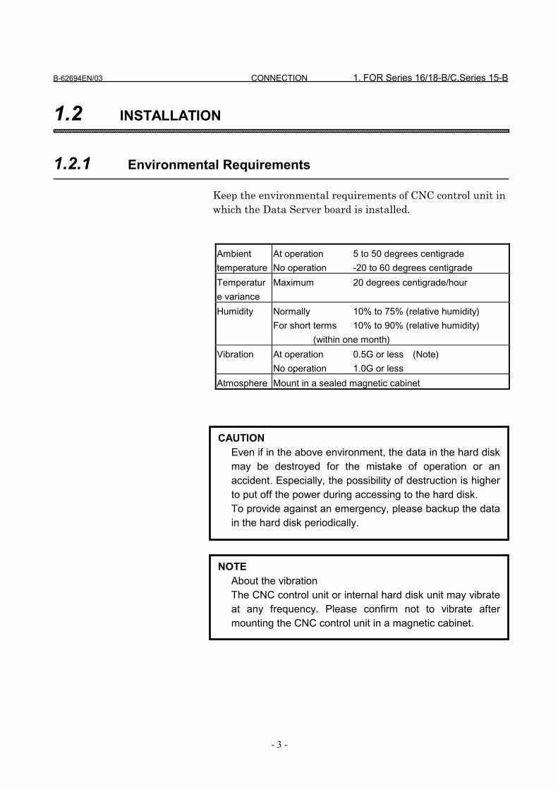
Keep the environmental requirements of CNC control unit inwhich the Data Server board is installed.
Ambienttemperature
At operation 5 to 50 degrees centigradeNo operation -20 to 60 degrees centigrade
Temperature variance
Maximum 20 degrees centigrade/hour
Humidity Normally 10% to 75% (relative humidity)For short terms 10% to 90% (relative humidity)
(within one month)Vibration At operation 0.5G or less (Note)
No operation 1.0G or lessAtmosphere Mount in a sealed magnetic cabinet
CAUTIONEven if in the above environment, the data in the hard diskmay be destroyed for the mistake of operation or anaccident. Especially, the possibility of destruction is higherto put off the power during accessing to the hard disk.To provide against an emergency, please backup the datain the hard disk periodically.
NOTEAbout the vibrationThe CNC control unit or internal hard disk unit may vibrateat any frequency. Please confirm not to vibrate aftermounting the CNC control unit in a magnetic cabinet.
1. FOR Series 16/18-B/C,Series 15-B CONNECTION B-62694EN/03
- 4 -
1.2.2 Cable Lead-in Diagram
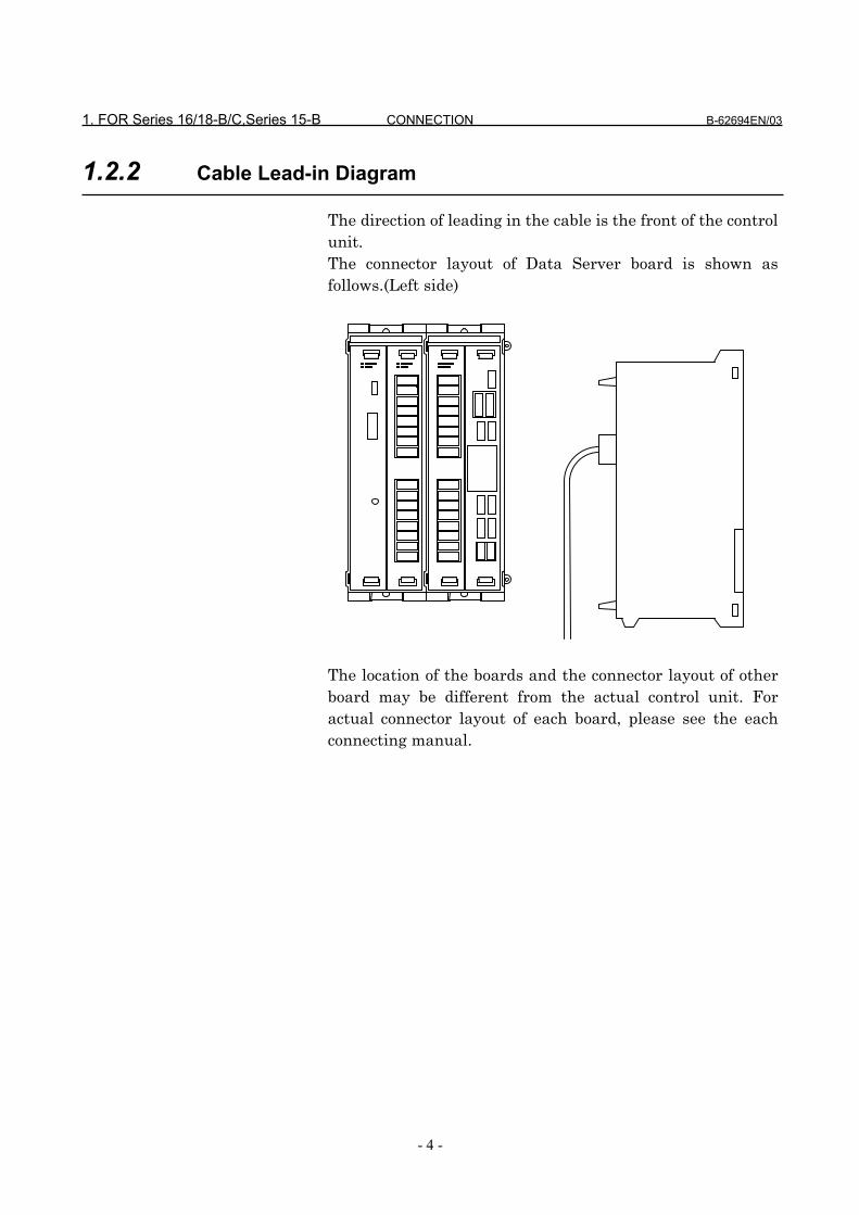
The direction of leading in the cable is the front of the controlunit.The connector layout of Data Server board is shown asfollows.(Left side)
The location of the boards and the connector layout of otherboard may be different from the actual control unit. Foractual connector layout of each board, please see the eachconnecting manual.
B-62694EN/03 CONNECTION 1. FOR Series 16/18-B/C,Series 15-B
- 5 -
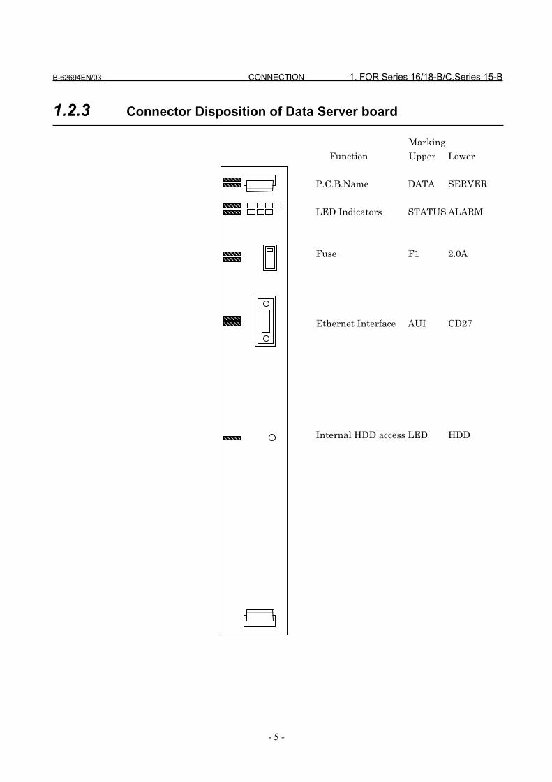
1.2.3 Connector Disposition of Data Server board
Marking
Function Upper Lower
P.C.B.Name DATA SERVER
LED Indicators STATUS ALARM
Fuse F1 2.0A
Ethernet Interface AUI CD27
Internal HDD access LED HDD

1. FOR Series 16/18-B/C,Series 15-B CONNECTION B-62694EN/03
- 6 -
1.3 GENERAL CONNECTION DIAGRAM
Please refer the connecting manual of CNC about the otherconnections.
Power Supply
CNC etc.
CD27
Rack
Station
TerminatorTransceiverTerminator Transceiver
Transceiver
Data Server
Station

B-62694EN/03 CONNECTION 2. FOR Series 16i/18i-A
- 7 -
2 FOR Series 16i/18i-A
The information for connection of the Data Server Interfaceboard for Series 16i/18i-A is described in this chapter.

2. FOR Series 16i/18i-A CONNECTION B-62694EN/03
- 8 -
2.1 CONSTRUCTION
The construction when the Data Server board is inserted intothe FANUC’s CNC control system is as follows.
Servo AMPFSSB
CNC
PMC
ServoMotor
OperationPanel
I/O board
I/O Unit etc.
LCD
MDI
EthernetData Server Workstation
etc.
HDD Unit

B-62694EN/03 CONNECTION 2. FOR Series 16i/18i-A
- 9 -
2.2 INSTALLATION
2.2.1 Environmental Requirements
Keep the environmental requirements of CNC control unit in whichthe Data Server board is installed.
AmbientTemperature
At operation 5 to 45 degrees centigradeNo operation -20 to 60 degrees centigrade
Temperaturevariance
Maximum 20 degrees centigrade/hour
Humidity Normally 10% to 75% (relative humidity)For short terms 10% to 90% (relative humidity)
(within one month)Vibration At operation 0.5G or less (Note)
No operation 1.0G or less (Note)Atmosphere Mount in a sealed magnetic cabinet
NOTEAbout the vibrationThe CNC control unit or in hard disk unit may vibrate at anyfrequency. Please confirm not to vibrate after mounting theCNC control unit in a magnetic cabinet.
CAUTIONEven if in the above environment, the data in the hard diskmay be destroyed for the mistake of operation or anaccident. Especially, the possibility of destruction is higherto put off the power during accessing to the hard disk.To provide against an emergency, please backup the datain the hard disk periodically.
2. FOR Series 16i/18i-A CONNECTION B-62694EN/03
- 10 -
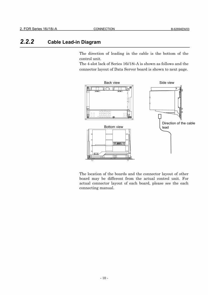
2.2.2 Cable Lead-in Diagram
The direction of leading in the cable is the bottom of thecontrol unit.The 4-slot lack of Series 16i/18i-A is shown as follows and theconnector layout of Data Server board is shown to next page.
The location of the boards and the connector layout of otherboard may be different from the actual control unit. Foractual connector layout of each board, please see the eachconnecting manual.
Direction of the cablelead
Back view Side view
Bottom view

B-62694EN/03 CONNECTION 2. FOR Series 16i/18i-A
- 11 -
2.2.3 Connector Disposition of Data Server board
Total edition 01A only
HDD InterfaceCNH1
Communic-ation LSI
OSC
CPU
CPU HALT
CUSTOMLSI
CUSTOMLSI
HDD Access
JNA
Parity AlarmSTATUS 4STATUS 3STATUS 2STATUS 1
AUICD27
2. FOR Series 16i/18i-A CONNECTION B-62694EN/03
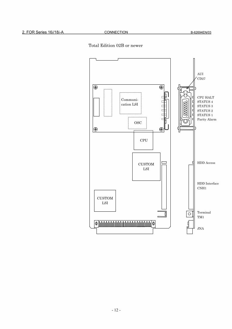
- 12 -
Total Edition 02B or newer
AUICD27
CPU HALTSTATUS 4
Communi-cation LSI
STATUS 2STATUS 3
STATUS 1Parity Alarm
OSC
CPU
HDD AccessCUSTOMLSI
CUSTOMLSI
HDD InterfaceCNH1
TerminalTM1
JNA

B-62694EN/03 CONNECTION 2. FOR Series 16i/18i-A
- 13 -
2.3 GENERAL CONNECTION DIAGRAM
2.3.1 General Connection Diagram
Please refer the connecting manual of CNC about the otherconnections.
Main CPU board
Rack
CNH1
CD27
Station
Other option board
HDD UnitData Server
Station
TerminatorTerminator TransceiverTransceiver
Transceiver

2. FOR Series 16i/18i-A CONNECTION B-62694EN/03
- 14 -
2.3.2 Connection of HDD Unit
The board of total edition 02B or newer must be assemble theplate which is to prevent slipping out of the hard diskconnector.To connect or disconnect the hard disk cable, this plate alsoneed to be connected or disconnected.(The board of total edition 01A has no terminal to assemblethe plate.)
1) Connection of the cable
2) Assemble of the plate
3) Fix the plate using the screw
To disconnect the hard disk cable, do the reveres way of theabove order.
Plate
HDD cable
Terminal
CAUTIONBefore connect or disconnect the cable to Data Serverboard, cut the power supply of CNC unit and confirm thatthe power is off.
B-62694EN/03 CONNECTION 2. FOR Series 16i/18i-A
- 15 -
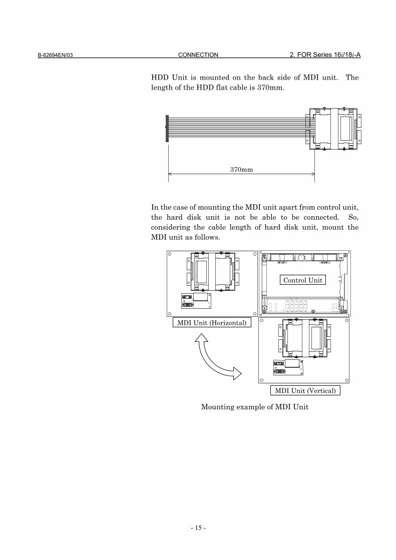
HDD Unit is mounted on the back side of MDI unit. Thelength of the HDD flat cable is 370mm.
In the case of mounting the MDI unit apart from control unit,the hard disk unit is not be able to be connected. So,considering the cable length of hard disk unit, mount theMDI unit as follows.
Mounting example of MDI Unit
370mm
Control Unit
MDI Unit (Horizontal)
MDI Unit (Vertical)

3. CONNECTION WITH NETWORK CONNECTION B-62694EN/03
- 16 -
3 CONNECTION WITH NETWORK
In this chapter, we describe the information about theconnection to the Ethernet.
NOTEPlease inquire of each maker about the construction ofnetwork or the condition of using the equipment except theData Server (transceiver and cable etc.) . To construct thenetwork, it is necessary not to be influenced by the noise.Separate the network line electrically from the noise sourceas power line and motor etc.. And the ground treatmentof each equipment must be done. And the high impedanceto the ground makes the obstacle of communication.Please test and confirm the communication before workingthe machine in earnest.The network trouble which is case of the equipment exceptthe Data Server is not guaranteed by FANUC.
CAUTIONBefore connect or disconnect the cable to Data Serverboard, cut the power supply of CNC unit and confirm thatthe power is off.

B-62694EN/03 CONNECTION 3. CONNECTION WITH NETWORK
- 17 -
3.1 CONNECTION WITH THE ETHERNET
Items Marks Conditions
Maximum segment length a 500m
Length between the
transceiver
b On the marking at intervals of
2.5m
Length of transceiver cable c Maximum 50m
Node number per segment n Maximum 100
MAU : TDK : CIU-1000 Ethernet Transceiver or equivalentSet for IEEE802.3 standard. (Include the hart-beat function)
Data ServerBoard
Transceiver Cable
Coaxial cable(Yellow cable)
MAU (Media Attachment Unit : Transceiver)
a
Transceiver cable
bCoaxial cable
cTerminator
MAU(Transceiver)Station
2
n31
NOTE1. The transceiver must be connected to the AUI of Data
Server using the transceiver cable. The transceiver cableshould be shielded. (Refer 3.4 )
2. The SQE TEST function (Hart-beat function) of thetransceiver must be set. There are some transceivers thatthe setting switch or jumper are inside the transceiver.

3. CONNECTION WITH NETWORK CONNECTION B-62694EN/03
- 18 -
3.2 AUI (Attachment Unit Interface) PIN CONFIGURATION
CD27 D-sub 15pin
Pin number Signal Meaning
1 No used
2 CI+ Control In circuit A
3 DO+ Data Out circuit A
4 No used
5 DI+ Data In circuit A
6 GND Voltage Common
7 No used
8 No used
9 CI- Control In circuit B
10 DO- Data Out circuit B
11 No used
12 DI- Data In circuit B
13 +12V Voltage Plus
14 No used
15 No used

B-62694EN/03 CONNECTION 3. CONNECTION WITH NETWORK
- 19 -
3.3 CONNECTION OF THE TRANSCEIVER CABLE
AUI of the Data Serve board is the connector with a slide lock.After connecting the transceiver cable, please lock the cable.
Slide lock
Push
AUI
Transceiver cable
Cable lock complete
3. CONNECTION WITH NETWORK CONNECTION B-62694EN/03
- 20 -
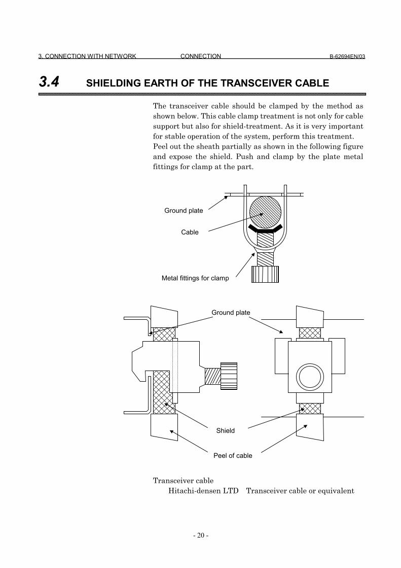
3.4 SHIELDING EARTH OF THE TRANSCEIVER CABLE
The transceiver cable should be clamped by the method asshown below. This cable clamp treatment is not only for cablesupport but also for shield-treatment. As it is very importantfor stable operation of the system, perform this treatment.Peel out the sheath partially as shown in the following figureand expose the shield. Push and clamp by the plate metalfittings for clamp at the part.
Transceiver cableHitachi-densen LTD Transceiver cable or equivalent
Ground plate
Cable
Metal fittings for clamp
Ground plate
Peel of cable
Shield
B-62694EN/03 CONNECTION 3. CONNECTION WITH NETWORK
- 21 -
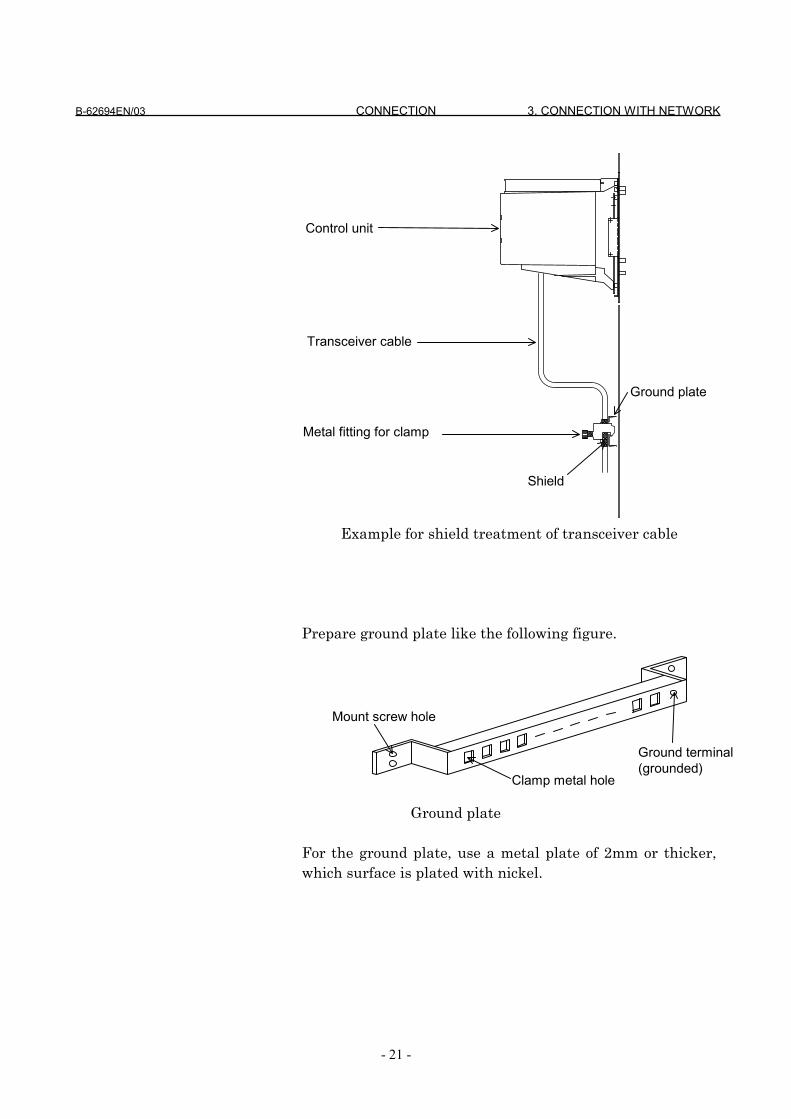
Example for shield treatment of transceiver cable
Prepare ground plate like the following figure.
Ground plate
For the ground plate, use a metal plate of 2mm or thicker,which surface is plated with nickel.
Control unit
Transceiver cable
Ground plate
Metal fitting for clamp
Shield
Mount screw hole
Ground terminal(grounded)
Clamp metal hole

3. CONNECTION WITH NETWORK CONNECTION B-62694EN/03
- 22 -
Ground plate holes
Cable clump outer diagram
Order specification for cable clumpA02B-0083-K301 ( 5 pieces )
Ground board8mm
12mm
20mm
Max 55mm
28mm
6mm
17mm

III. MAINTENANCE

B-62694EN/03 MAINTENANCE 1.FOR Series 16/18-B/C, Series 15-B
- 1 -
1 FOR Series 16/18-B/C, Series 15-B
In this section, the maintenance information about Series16/18-B/C and Series 15-B is described.

1.FOR Series 16/18-B/C, Series 15-B MAINTENANCE B-62694EN/03
- 2 -
1.1 SYSTEM BLOCK DIAGRAM
Name Specification Note
Data Server Board A16B-2202-0630
A02B-0207-C050 85MB
HDD Unit A02B-0207-C051 256MB
A02B-0207-C053 810MB
Fuse A08B-0048-K101 2.0A
LANControllerSRAM
ROM
DV/RV
HDD
DRAM
CPU
CustomLSI
SRAM
10BASE5CN1
Power Supply Unit
CNC Main CPU Board
Other Option BoardBack P
lane
Data Server P.C.B.

B-62694EN/03 MAINTENANCE 1.FOR Series 16/18-B/C, Series 15-B
- 3 -
1.2 PARTS LAYOUT
CPU
+12V
LED
C01F81
ROM
JNA
HDDBack Plane Connector
DATASERVER
STATUSALARM
F12.0A
AUICD27
HDD
Printedletters
: Check Pin
Specification : A02B-0213-J001
1.FOR Series 16/18-B/C, Series 15-B MAINTENANCE B-62694EN/03
- 4 -
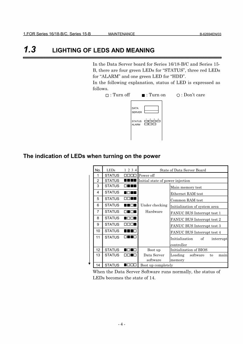
1.3 LIGHTING OF LEDS AND MEANING
In the Data Server board for Series 16/18-B/C and Series 15-B, there are four green LEDs for “STATUS”, three red LEDsfor “ALARM” and one green LED for “HDD”.In the following explanation, status of LED is expressed asfollows.
: Turn off : Turn on : Don’t care
The indication of LEDs when turning on the power
No. LEDs 1 2 3 4 State of Data Server Board1 STATUS Power off2 STATUS Initial state of power injection3 STATUS Main memory test4 STATUS Ethernet RAM test5 STATUS Common RAM test6 STATUS Under checking Initialization of system area7 STATUS Hardware FANUC BUS Interrupt test 18 STATUS FANUC BUS Interrupt test 29 STATUS FANUC BUS Interrupt test 3
10 STATUS FANUC BUS Interrupt test 411 STATUS Initialization of interrupt
controller12 STATUS Boot up Initialization of BIOS13 STATUS Data Server
softwareLoading software to mainmemory
14 STATUS Boot up completely
When the Data Server Software runs normally, the status ofLEDs becomes the state of 14.
DATASERVER
1 2 3 4STATUSALARM
B-62694EN/03 MAINTENANCE 1.FOR Series 16/18-B/C, Series 15-B
- 5 -
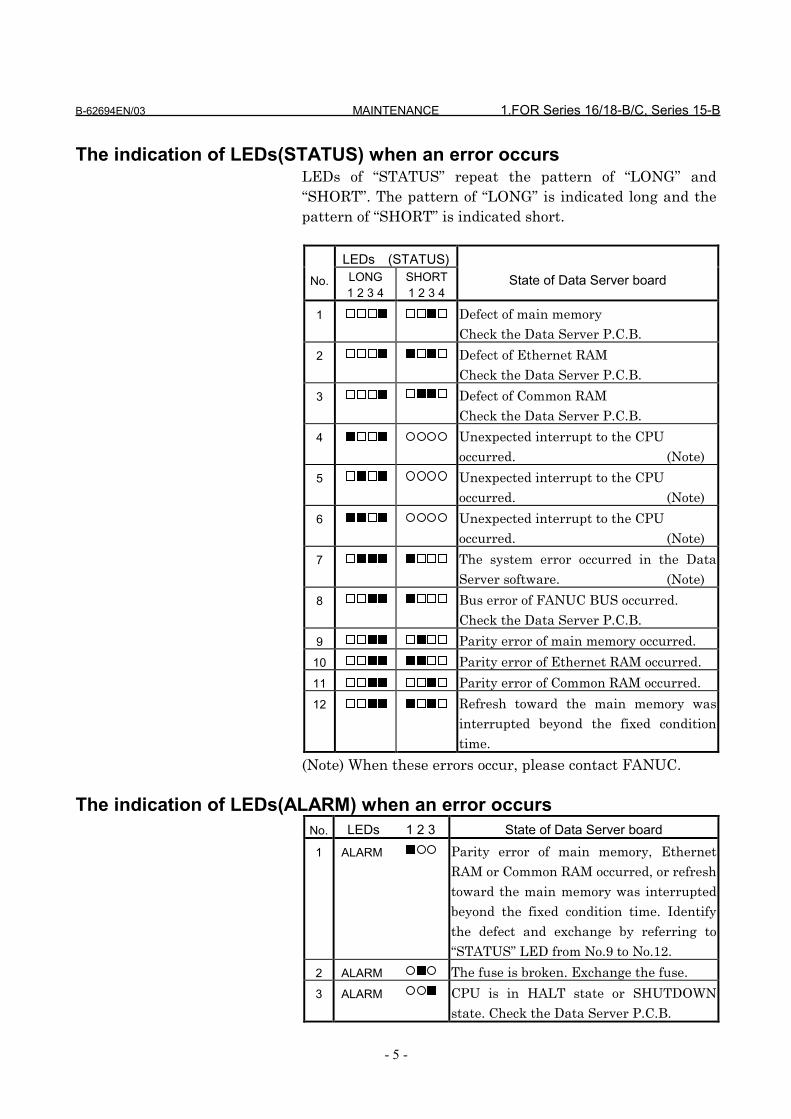
The indication of LEDs(STATUS) when an error occursLEDs of “STATUS” repeat the pattern of “LONG” and“SHORT”. The pattern of “LONG” is indicated long and thepattern of “SHORT” is indicated short.
LEDs (STATUS)No. LONG
1 2 3 4SHORT1 2 3 4
State of Data Server board
1 Defect of main memory
Check the Data Server P.C.B.
2 Defect of Ethernet RAM
Check the Data Server P.C.B.
3 Defect of Common RAM
Check the Data Server P.C.B.
4 Unexpected interrupt to the CPU
occurred. (Note)
5 Unexpected interrupt to the CPU
occurred. (Note)
6 Unexpected interrupt to the CPU
occurred. (Note)
7 The system error occurred in the Data
Server software. (Note)
8 Bus error of FANUC BUS occurred.
Check the Data Server P.C.B.
9 Parity error of main memory occurred.
10 Parity error of Ethernet RAM occurred.
11 Parity error of Common RAM occurred.
12 Refresh toward the main memory was
interrupted beyond the fixed condition
time.
(Note) When these errors occur, please contact FANUC.
The indication of LEDs(ALARM) when an error occursNo. LEDs 1 2 3 State of Data Server board1 ALARM Parity error of main memory, Ethernet
RAM or Common RAM occurred, or refresh
toward the main memory was interrupted
beyond the fixed condition time. Identify
the defect and exchange by referring to
“STATUS” LED from No.9 to No.12.
2 ALARM The fuse is broken. Exchange the fuse.
3 ALARM CPU is in HALT state or SHUTDOWN
state. Check the Data Server P.C.B.

1.FOR Series 16/18-B/C, Series 15-B MAINTENANCE B-62694EN/03
- 6 -
1.4 HOW TO EXCHANGE A FUSE
(1) Check a fuse on the front panel of the Data Server P.C.B.and confirm whether it is broken.There is a little window in the fuse and a white markerappears there at the time of the breakage.
(2) Remove the cause of the fuse cutting.(3) After the broken fuse is pulled out, insert the new fuse of
the same specification.
Fuse
Fuse Specification :A08B-0048-K101
Capacity : 2.0AUse : For Ethernet power

B-62694EN/03 MAINTENANCE 2.FOR Series 16i/18i-A
- 7 -
2 FOR Series 16i/18i-A
In this section, the maintenance information about Series16i/18i-A is described.

2.FOR Series 16i/18i-A MAINTENANCE B-62694EN/03
- 8 -
2.1 SYSTEM BLOCK DIAGRAM
Name Specification Note
Data Server Board A20B-8100-0160
Sub Board A20B-2002-0590 latter edition than 02B
HDD Unit A02B-0236-C252 810MB
Note) In case of latter edition than 02B, the DC/DCconverter is loaded on the sub board.
LANController
EthernetRAM
DV/RV
DRAM
DC/DC
CustomLSI
CPU
CustomLSI
SRAM
HDDCNH1
AUICD27
CNC Main CPU Board
Other Option BoardBack P
lane
FA
NU
C B
US
Data Server P.C.B.
Note)

B-62694EN/03 MAINTENANCE 2.FOR Series 16i/18i-A
- 9 -
2.2 PARTS LAYOUT
Parts Layout (Only 01A edition)
CommunicationController
OSC
CPU
CPU HALT
CustomLSI
CustomLSI
HDD Access
HDD InterfaceCNH1
JNA
Parity AlarmSTATUS 4STATUS 3STATUS 2STATUS 1
AUICD27

2.FOR Series 16i/18i-A MAINTENANCE B-62694EN/03
- 10 -
Parts Layout (Latter edition than 02B)
AUICD27
Interface Board : A20B-2002-0590
CPU HALTSTATUS 4Communication
LSISTATUS 2STATUS 3
STATUS 1Parity Alarm
OSC
CPU
HDD AccessCustomLSI
CustomLSI
HDD InterfaceCNH1
TerminalTM1
JNA
B-62694EN/03 MAINTENANCE 2.FOR Series 16i/18i-A
- 11 -
2.3 LIGHTING OF LED AND MEANING
In the Data Server Board for Series 16i/18i-A, there are fourgreen LEDs for “STATUS”, two red LEDs for “ALARM” andone green LED for “HDD”. But, LEDs’ position is different bythe edition of the Data Server board.The LEDs’ position is displayed for each edition.In the following explanation, status of LED is expressed asfollows.
: Turn off : Turn on : Don’t care

2.FOR Series 16i/18i-A MAINTENANCE B-62694EN/03
- 12 -
2.3.1 In case of edition 01A
The indication of LEDs when turning on the power
No. LEDs 4 3 2 1 State of Data Server Board1 STATUS Power off2 STATUS Initial state of power injection3 STATUS Main memory test4 STATUS Ethernet RAM test5 STATUS Common RAM test6 STATUS Under checking Initialization of system area7 STATUS Hardware FANUC BUS Interrupt test 18 STATUS FANUC BUS Interrupt test 29 STATUS FANUC BUS Interrupt test 3
10 STATUS FANUC BUS Interrupt test 411 STATUS Initialization of interrupt
controller12 STATUS Boot up Initialization of BIOS13 STATUS Data Server
softwareLoading software to mainmemory
14 STATUS Boot up completely
When the Data Server Software runs normally, the status ofLEDs becomes the state of 14.
ST
AT
US
1
HD
D A
ccess
CP
U H
AL
T
Parity A
larm
ST
AT
US
4
ST
AT
US
3
ST
AT
US
2
OSC
CPU
CustomLSI

B-62694EN/03 MAINTENANCE 2.FOR Series 16i/18i-A
- 13 -
The indication of LEDs(STATUS) when an error occursLEDs of “STATUS” repeat the pattern of “LONG” and“SHORT”. The pattern of “LONG” is indicated long and thepattern of “SHORT” is indicated short.
LEDs (STATUS)No. LONG
4 3 2 1SHORT4 3 2 1
State of Data Server board
1 Defect of main memory
Check the Data Server P.C.B.
2 Defect of Ethernet RAM
Check the Data Server P.C.B.
3 Defect of Common RAM
Check the Data Server P.C.B.
4 Unexpected interrupt to the CPU
occurred. (Note)
5 Unexpected interrupt to the CPU
occurred. (Note)
6 Unexpected interrupt to the CPU
occurred. (Note)
7 The system error occurred in the Data
Server software. (Note)
8 Bus error of FANUC BUS occurred.
Check the Data Server P.C.B.
9 Parity error of main memory occurred.
10 Parity error of Ethernet RAM occurred.
11 Parity error of Common RAM occurred.
(Note) When these errors occur, please contact FANUC.
The indication of LEDs(ALARM) when an error occursNo. Lighting LED State of Data Server board1 Parity Alarm Parity error of main memory, Ethernet
RAM or Common RAM occurred. Identify
the defect and exchange it by referring to
“STATUS” LED from No.9 to No.11.
2 CPU HALT CPU is in HALT state or SHUTDOWN
state. Check the Data Server P.C.B.

2.FOR Series 16i/18i-A MAINTENANCE B-62694EN/03
- 14 -
2.3.2 In case of latter edition than 02B
The indication of LEDs when turning on the power
No. LEDs 1 2 3 4 State of Data Server Board1 STATUS Power off2 STATUS Initial state of power injection3 STATUS Main memory test4 STATUS Ethernet RAM test5 STATUS Common RAM test6 STATUS Under checking Initialization of system area7 STATUS Hardware FANUC BUS Interrupt test 18 STATUS FANUC BUS Interrupt test 29 STATUS FANUC BUS Interrupt test 3
10 STATUS FANUC BUS Interrupt test 411 STATUS Initialization of interrupt
controller12 STATUS Boot up Initialization of BIOS13 STATUS Data Server
softwareLoading software to mainmemory
14 STATUS Boot up completely
When the Data Server Software runs normally, the status ofLEDs becomes the state of 14.
HD
D A
ccess
CP
U H
AL
T
ST
AT
US
4
ST
AT
US
3
ST
AT
US
2
ST
AT
US
1
Parity A
larmOSC
CPU
CommunicationLSI
CustomLSI
Note) The Sub Board is displayed by a dotted line.

B-62694EN/03 MAINTENANCE 2.FOR Series 16i/18i-A
- 15 -
The indication of LEDs(STATUS) when an error occursLEDs of “STATUS” repeat the pattern of “LONG” and“SHORT”. The pattern of “LONG” is indicated long and thepattern of “SHORT” is indicated short.
LEDs (STATUS)No. LONG
1 2 3 4SHORT1 2 3 4
State of Data Server board
1 Defect of main memory
Check the Data Server P.C.B.
2 Defect of Ethernet RAM
Check the Data Server P.C.B.
3 Defect of Common RAM
Check the Data Server P.C.B.
4 Unexpected interrupt to the CPU
occurred. (Note)
5 Unexpected interrupt to the CPU
occurred. (Note)
6 Unexpected interrupt to the CPU
occurred. (Note)
7 The system error occurred in the Data
Server software. (Note)
8 Bus error of FANUC BUS occurred.
Check the Data Server P.C.B.
9 Parity error of main memory occurred.
10 Parity error of Ethernet RAM occurred.
11 Parity error of Common RAM occurred.
(Note) When these errors occur, please contact FANUC.
The indication of LEDs(ALARM) when an error occursNo. Lighting LED State of Data Server board1 Parity Alarm Parity error of main memory, Ethernet
RAM or Common RAM occurred. Identify
the defect and exchange it by referring to
“STATUS” LED from No.9 to No.11.
2 CPU HALT CPU is in HALT state or SHUTDOWN
state. Check the Data Server P.C.B.

IV. OPERATION

B-62694EN/03 OPERATION 1.FOR Series 16/18-B/C, Series 16i/18i-A
- 1 -
1 FOR Series 16/18-B/C, Series 16i/18i-A
The operation of Data Server for Series 16/18-B/C and Series16i/18i-A is described in this chapter.

1.FOR Series 16/18-B/C, Series 16i/18i-A OPERATION B-62694EN/03
- 2 -
1.1 OUTLINE
By using this function, the following items can be achieved.(1) Drive high-speed machining operation by calling the
subprogram from a built-in hard disk on the Data Serverboard (described as “HDD” below).
(2) Input a NC program in the Host Computer into the HDDby using FTP.Output a NC program in the HDD into the Host Computerby using FTP.
(3) Input a NC program in the HDD into the memory of theCNC.Output a NC program in the memory of the CNC into theHDD.
(4) Delete NC programs and display the table of NC programsin the HDD.
NOTEThere is the software option “PROGRAM NUMBER O8-DIGIT” in the Series 16/18-C and Series 16i/18i-A, but theData Server function doesn’t support this feature.So, the Data Server function and the software option“PROGRAM NUMBER O8-DIGIT” are not used at thesame time.

B-62694EN/03 OPERATION 1.FOR Series 16/18-B/C, Series 16i/18i-A
- 3 -
1.1.1 Notice when you use for the first time
WARNING1 If you use this function for the first time, you must initiate
the HDD according to “1.8.2 Formatting the built-in harddisk” and input the setting data according to “1.2 SETTINGSCREEN”. And turn off and then turn on the power of theCNC.If you use this function before you operate these, we don’tguarantee that this function operates normally.
2 About FTP on the Ethernet, when you use this function forthe first time, please set Ethernet addresses carefully andcheck this function on your environment according to yournetwork administrator’s advice.If you set wrong Ethernet addresses, it may make a heavyeffect on your network.
CAUTION1 If you turn off the power during reading the data from the
HDD or writing to the HDD, it may make the registered filein the HDD broken.So, you must not turn off the power during executing theData Server functions.
2 Be sure to take the backup of the data in the HDD againstan emergency.
1.FOR Series 16/18-B/C, Series 16i/18i-A OPERATION B-62694EN/03
- 4 -
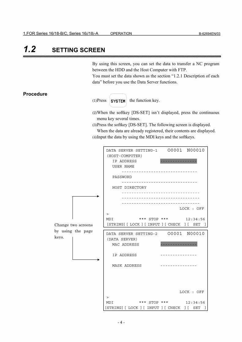
1.2 SETTING SCREEN
By using this screen, you can set the data to transfer a NC programbetween the HDD and the Host Computer with FTP.You must set the data shown as the section “1.2.1 Description of eachdata” before you use the Data Server functions.
Procedure(1) Press the function key. (2) When the softkey [DS-SET] isn’t displayed, press the continuous
menu key several times.(3) Press the softkey [DS-SET]. The following screen is displayed.
When the data are already registered, their contents are displayed.(4) Input the data by using the MDI keys and the softkeys.
SSSSYYYYSSSSTTTTEMEMEMEM
DATA SERVER SETTING-1 O0001 N00010(HOST-COMPUTER)
IP ADDRESS ---------------USER NAME
-------------------------------PASSWORD
-------------------------------HOST DIRECTORY
------------------------------------------------------------------------------------------------
LOCK : OFF>MDI *** STOP *** 12:34:56[STRING][ LOCK ][ INPUT ][ CHECK ][ SET ]
DATA SERVER SETTING-2 O0001 N00010(DATA SERVER)
MAC ADDRESS ---------------
IP ADDRESS ---------------
MASK ADDRESS ---------------
LOCK : OFF>MDI *** STOP *** 12:34:56[STRING][ LOCK ][ INPUT ][ CHECK ][ SET ]
Change two screens
by using the page
keys.

B-62694EN/03 OPERATION 1.FOR Series 16/18-B/C, Series 16i/18i-A
- 5 -
In the above screen, means a cursor--- means a blank.
If the data are already registered, then these data aredisplayed except for the PASSWORD.About the PASSWORD, only when you set the password, itwill be displayed.
1.FOR Series 16/18-B/C, Series 16i/18i-A OPERATION B-62694EN/03
- 6 -
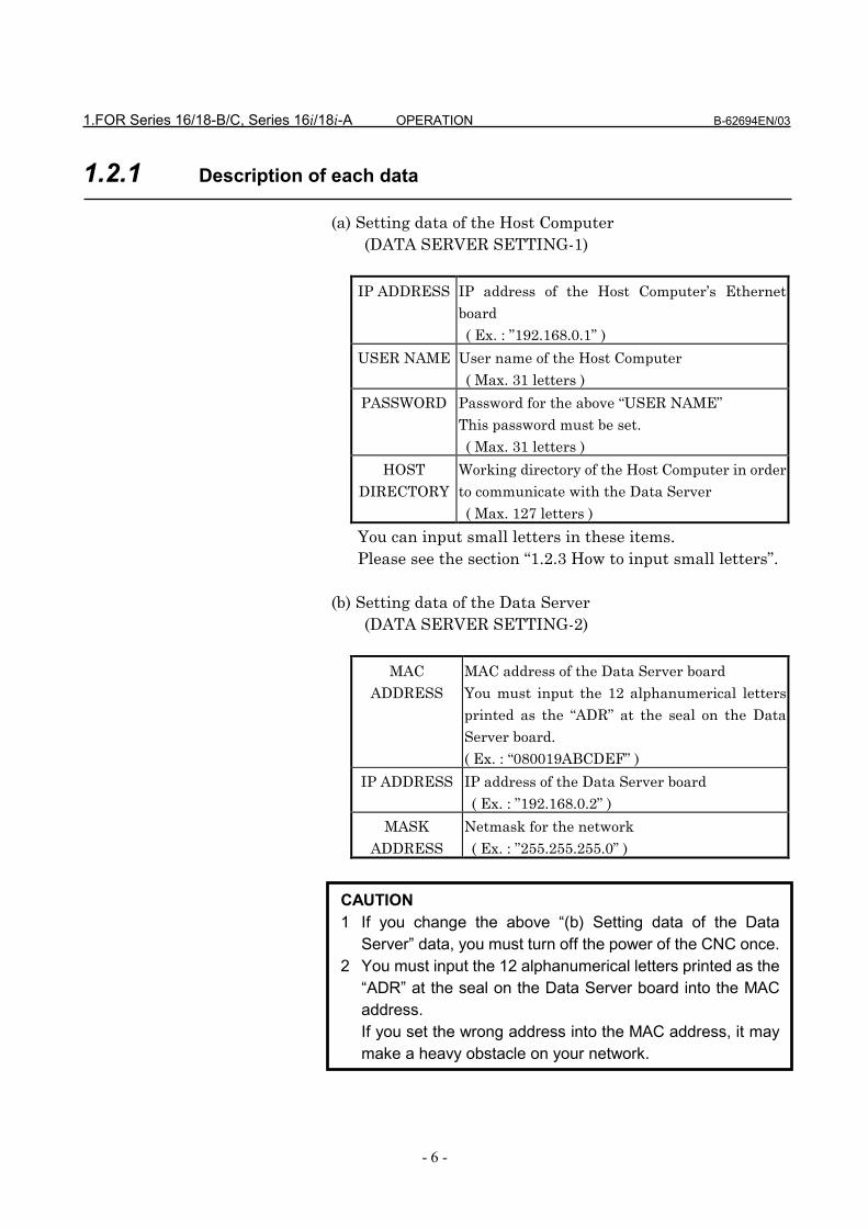
1.2.1 Description of each data
(a) Setting data of the Host Computer(DATA SERVER SETTING-1)
IP ADDRESS IP address of the Host Computer’s Ethernet
board
( Ex. : ”192.168.0.1” )
USER NAME User name of the Host Computer
( Max. 31 letters )
PASSWORD Password for the above “USER NAME”
This password must be set.
( Max. 31 letters )
HOST
DIRECTORY
Working directory of the Host Computer in order
to communicate with the Data Server
( Max. 127 letters )
You can input small letters in these items.Please see the section “1.2.3 How to input small letters”.
(b) Setting data of the Data Server(DATA SERVER SETTING-2)
MAC
ADDRESS
MAC address of the Data Server board
You must input the 12 alphanumerical letters
printed as the “ADR” at the seal on the Data
Server board.
( Ex. : “080019ABCDEF” )
IP ADDRESS IP address of the Data Server board
( Ex. : ”192.168.0.2” )
MASK
ADDRESS
Netmask for the network
( Ex. : ”255.255.255.0” )
CAUTION1 If you change the above “(b) Setting data of the Data
Server” data, you must turn off the power of the CNC once.2 You must input the 12 alphanumerical letters printed as the
“ADR” at the seal on the Data Server board into the MACaddress.If you set the wrong address into the MAC address, it maymake a heavy obstacle on your network.

B-62694EN/03 OPERATION 1.FOR Series 16/18-B/C, Series 16i/18i-A
- 7 -
The meanings of each address are as follows:MAC ADDRESS : It means the address that identifies
each machine connected by Ethernet inthe MAC layer.It must be unique in the network.
IP ADDRESS : It means the address that identifieseach machine connected by Ethernet inthe Network layer.It must be unique in the network.
MASK ADDRESS : It means a bit typed value which takesout the part of the network addressfrom the IP address.
Refer to “APPENDIX C. Ethernet technical terms” indetail.

1.FOR Series 16/18-B/C, Series 16i/18i-A OPERATION B-62694EN/03
- 8 -
1.2.2 How to input data
In this section, how to input data is explained.
Procedure(1) Move the cursor to an item that you will input.(2) Input the data by using the MDI keys.(3) Press the softkey [INPUT]. In this screen, the MDI key can’t be used.
Ex.) In case of setting “192.168.0.1” into the IP ADDRESSitem(1) Move the cursor and put the cursor on the IP
ADDRESS item.
(2) Input the data “192.168.0.1” by using the MDI keys.
(3)Press the softkey [INPUT].
INPUTINPUTINPUTINPUT
DATA SERVER SETTING-1 O0001 N00010(HOST-COMPUTER)
IP ADDRESS ---------------USER NAME
>MDI *** STOP *** 12:34:56[STRING][ LOCK ][ INPUT ][ CHECK ][ SET ]
~ ~
DATA SERVER SETTING-1 O0001 N00010(HOST-COMPUTER)
IP ADDRESS ---------------USER NAME
> 192.168.0.1MDI *** STOP *** 12:34:56[STRING][ LOCK ][ INPUT ][ CHECK ][ SET ]
~ ~
DATA SERVER SETTING-1 O0001 N00010(HOST-COMPUTER)
IP ADDRESS 192.168.0.1----USER NAME
>MDI *** STOP *** 12:34:56[STRING][ LOCK ][ INPUT ][ CHECK ][ SET ]
~ ~

B-62694EN/03 OPERATION 1.FOR Series 16/18-B/C, Series 16i/18i-A
- 9 -
NOTEThe above setting data of Data Server are different fromother NC parameters. They are saved in the HDD.Therefore you must save the setting data after inputting orchanging these data.Please refer to the section “1.2.5 How to save modifieddata”.

1.FOR Series 16/18-B/C, Series 16i/18i-A OPERATION B-62694EN/03
- 10 -
1.2.3 How to input small letters
When you input the setting data for the Host Computer, youcan input small letters.How to input small letters is described as follows.
Procedure(1) Press the softkey [ LOCK ] before inputting small letters.
Confirm the “LOCK : ON” on the right and low of thescreen.
(2) Then the inputted letter from the MDI keys is changed to asmall letter.
(3) To cancel this mode, press the softkey [ LOCK ] again orset the data by using the softkey [INPUT].Confirm the “LOCK : OFF” on the right and low of thescreen.
B-62694EN/03 OPERATION 1.FOR Series 16/18-B/C, Series 16i/18i-A
- 11 -
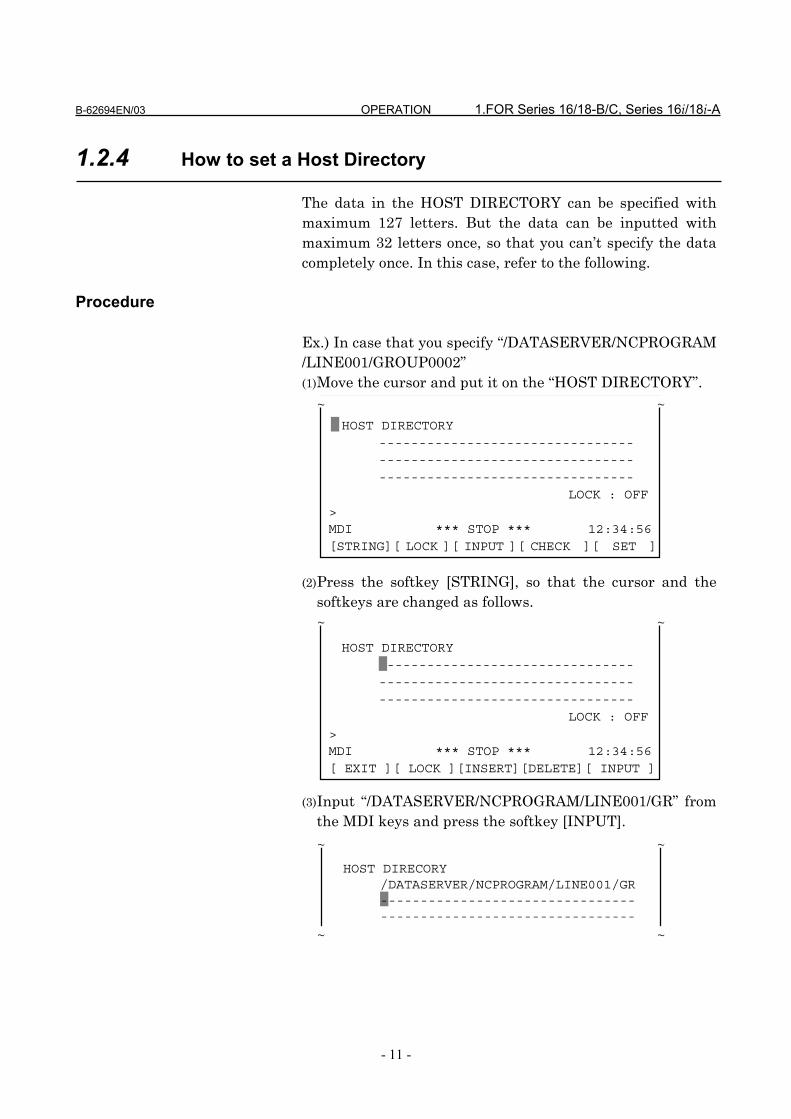
1.2.4 How to set a Host Directory
The data in the HOST DIRECTORY can be specified withmaximum 127 letters. But the data can be inputted withmaximum 32 letters once, so that you can’t specify the datacompletely once. In this case, refer to the following.
Procedure
Ex.) In case that you specify “/DATASERVER/NCPROGRAM/LINE001/GROUP0002”(1) Move the cursor and put it on the “HOST DIRECTORY”. (2) Press the softkey [STRING], so that the cursor and the
softkeys are changed as follows. (3) Input “/DATASERVER/NCPROGRAM/LINE001/GR” from
the MDI keys and press the softkey [INPUT].
HOST DIRECTORY------------------------------------------------------------------------------------------------
LOCK : OFF>MDI *** STOP *** 12:34:56[STRING][ LOCK ][ INPUT ][ CHECK ][ SET ]
HOST DIRECORY/DATASERVER/NCPROGRAM/LINE001/GR----------------------------------------------------------------
HOST DIRECTORY------------------------------------------------------------------------------------------------
LOCK : OFF>MDI *** STOP *** 12:34:56[ EXIT ][ LOCK ][INSERT][DELETE][ INPUT ]
~ ~
~ ~
~ ~
~ ~
1.FOR Series 16/18-B/C, Series 16i/18i-A OPERATION B-62694EN/03
- 12 -
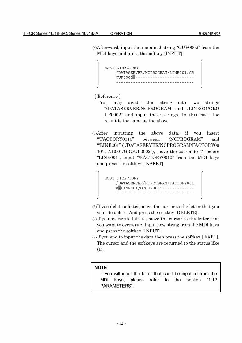
(4) Afterward, input the remained string “OUP0002” from theMDI keys and press the softkey [INPUT].
[ Reference ]
You may divide this string into two strings“/DATASERVER/NCPROGRAM” and ”/LINE001/GROUP0002” and input these strings. In this case, theresult is the same as the above.
(5) After inputting the above data, if you insert
“/FACTORY0010” between “NCPROGRAM” and“/LINE001” (”/DATASERVER/NCPROGRAM/FACTORY0010/LINE001/GROUP0002”), move the cursor to “/” before“LINE001”, input “/FACTORY0010” from the MDI keysand press the softkey [INSERT].
(6) If you delete a letter, move the cursor to the letter that you
want to delete. And press the softkey [DELETE].(7) If you overwrite letters, move the cursor to the letter that
you want to overwrite. Input new string from the MDI keysand press the softkey [INPUT].
(8) If you end to input the data then press the softkey [ EXIT ].The cursor and the softkeys are returned to the status like(1).
NOTEIf you will input the letter that can’t be inputted from theMDI keys, please refer to the section “1.12PARAMETERS”.
HOST DIRECTORY/DATASERVER/NCPROGRAM/LINE001/GROUP0002---------------------------------------------------------
~ ~
~ ~
HOST DIRECTORY/DATASERVER/NCPROGRAM/FACTORY0010/LINE001/GROUP0002---------------------------------------------
~ ~
~ ~
B-62694EN/03 OPERATION 1.FOR Series 16/18-B/C, Series 16i/18i-A
- 13 -
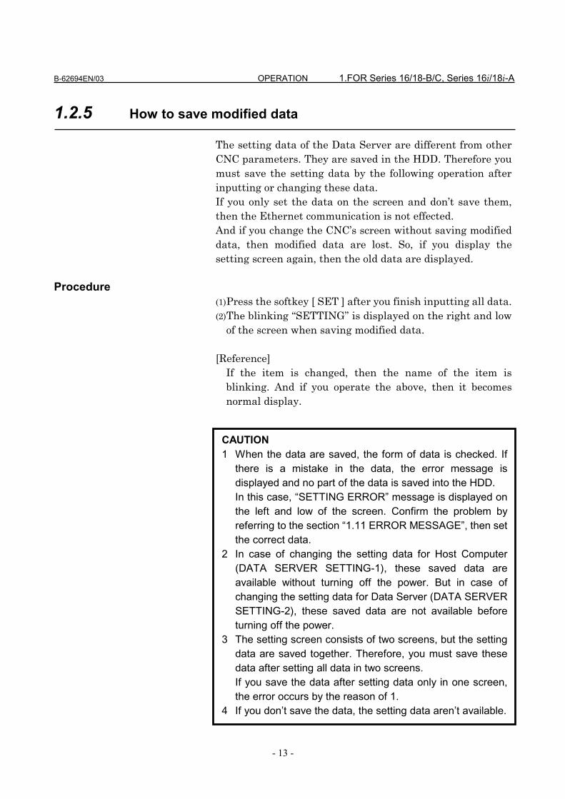
1.2.5 How to save modified data
The setting data of the Data Server are different from otherCNC parameters. They are saved in the HDD. Therefore youmust save the setting data by the following operation afterinputting or changing these data.If you only set the data on the screen and don’t save them,then the Ethernet communication is not effected.And if you change the CNC’s screen without saving modifieddata, then modified data are lost. So, if you display thesetting screen again, then the old data are displayed.
Procedure(1) Press the softkey [ SET ] after you finish inputting all data.(2) The blinking “SETTING” is displayed on the right and low
of the screen when saving modified data.
[Reference]If the item is changed, then the name of the item isblinking. And if you operate the above, then it becomesnormal display.
CAUTION1 When the data are saved, the form of data is checked. If
there is a mistake in the data, the error message isdisplayed and no part of the data is saved into the HDD.In this case, “SETTING ERROR” message is displayed onthe left and low of the screen. Confirm the problem byreferring to the section “1.11 ERROR MESSAGE”, then setthe correct data.
2 In case of changing the setting data for Host Computer(DATA SERVER SETTING-1), these saved data areavailable without turning off the power. But in case ofchanging the setting data for Data Server (DATA SERVERSETTING-2), these saved data are not available beforeturning off the power.
3 The setting screen consists of two screens, but the settingdata are saved together. Therefore, you must save thesedata after setting all data in two screens.If you save the data after setting data only in one screen,the error occurs by the reason of 1.
4 If you don’t save the data, the setting data aren’t available.

1.FOR Series 16/18-B/C, Series 16i/18i-A OPERATION B-62694EN/03
- 14 -
1.3 NC PROGRAM MANAGEMENT FUNCTION
By using Data Server function, the following items can beachieved.
(1) Displaying the table of NC programsDisplay the table of NC programs in the HDD inalphanumerical order.
(2) Searching a NC programSearch a NC program in the HDD and display it.
(3) Deleting NC programsDelete NC programs from the HDD
(4) Getting a NC programGet a NC program from the Host Computer with GETcommand of FTP
(5) Putting a NC programPut a NC program into the Host Computer with PUTcommand of FTP
(6) List-Getting NC programsGet NC programs that are appointed in the List-Filefrom the Host Computer with GET command of FTP
(7) List-Putting NC programsPut NC programs that are appointed in the List-File intothe Host Computer with PUT command of FTP
(8) List-Deleting NC programsDelete NC programs that are appointed in the List-Filefrom the HDD
CAUTION1 Two or more items of the above can’t be operated at the
same time.2 When you are operating “Calling a subprogram with M198”
or “DNC Operation” on the buffer mode ( See “1.10BUFFER MODE” ), you can’t operate the above functions.And if you are operating neither “Calling a subprogram withM198” nor “DNC Operation” on the buffer mode, you canoperate the above functions. But in case that you create anew file into the HDD by operating “Getting a NCprogram” ,etc., the remainder of the HDD is decreased bythis new file. In this case, you may not operate on thebuffer mode because of the shortage of the HDD’sremainder. Therefore, in case of using the Data Server onthe buffer mode, you must not use “Getting a NCprogram” ,etc.

B-62694EN/03 OPERATION 1.FOR Series 16/18-B/C, Series 16i/18i-A
- 15 -
1.3.1 Displaying the table of NC programs
You can display the table of NC programs in the HDD.
Procedure(1) Press the function key. (2) When the softkey [DS-DIR] isn’t displayed, press the
continuous menu key several times.(3) Press the softkey [DS-DIR], then the following screen is
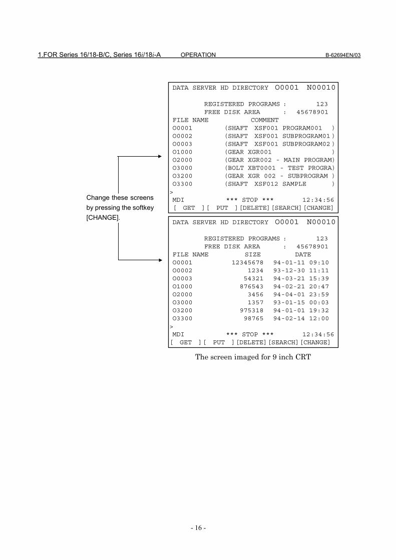
displayed.(4) Scroll the previous or next screen by pressing the page key.(5) Change the contents of the screen by pressing the softkey
[CHANGE].
The screens imaged for 9 inch CRT and for 14 inch CRT areshown as follows.In this manual, 9 inch CRT is used for the example screens.
PPPPRRRROOOOGGGG
1.FOR Series 16/18-B/C, Series 16i/18i-A OPERATION B-62694EN/03
- 16 -
The screen imaged for 9 inch CRT
DATA SERVER HD DIRECTORY O0001 N00010
REGISTERED PROGRAMS : 123FREE DISK AREA : 45678901
FILE NAME COMMENTO0001 (SHAFT XSF001 PROGRAM001 )O0002 (SHAFT XSF001 SUBPROGRAM01 )O0003 (SHAFT XSF001 SUBPROGRAM02 )O1000 (GEAR XGR001 )O2000 (GEAR XGR002 - MAIN PROGRAM)O3000 (BOLT XBT0001 - TEST PROGRA)O3200 (GEAR XGR 002 - SUBPROGRAM )O3300 (SHAFT XSF012 SAMPLE )>MDI *** STOP *** 12:34:56[ GET ][ PUT ][DELETE][SEARCH][CHANGE]
DATA SERVER HD DIRECTORY O0001 N00010
REGISTERED PROGRAMS : 123FREE DISK AREA : 45678901
FILE NAME SIZE DATEO0001 12345678 94-01-11 09:10O0002 1234 93-12-30 11:11O0003 54321 94-03-21 15:39O1000 876543 94-02-21 20:47O2000 3456 94-04-01 23:59O3000 1357 93-01-15 00:03O3200 975318 94-01-01 19:32O3300 98765 94-02-14 12:00>MDI *** STOP *** 12:34:56[ GET ][ PUT ][DELETE][SEARCH][CHANGE]
Change these screensby pressing the softkey[CHANGE].
B-62694EN/03 OPERATION 1.FOR Series 16/18-B/C, Series 16i/18i-A
- 17 -
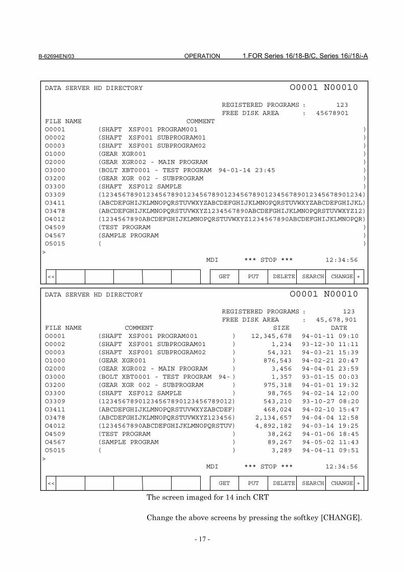
The screen imaged for 14 inch CRT
Change the above screens by pressing the softkey [CHANGE].
DATA SERVER HD DIRECTORY O0001 N00010
REGISTERED PROGRAMS : 123FREE DISK AREA : 45678901
FILE NAME COMMENTO0001 (SHAFT XSF001 PROGRAM001 )O0002 (SHAFT XSF001 SUBPROGRAM01 )O0003 (SHAFT XSF001 SUBPROGRAM02 )O1000 (GEAR XGR001 )O2000 (GEAR XGR002 - MAIN PROGRAM )O3000 (BOLT XBT0001 - TEST PROGRAM 94-01-14 23:45 )O3200 (GEAR XGR 002 - SUBPROGRAM )O3300 (SHAFT XSF012 SAMPLE )O3309 (1234567890123456789012345678901234567890123456789012345678901234)O3411 (ABCDEFGHIJKLMNOPQRSTUVWXYZABCDEFGHIJKLMNOPQRSTUVWXYZABCDEFGHIJKL)O3478 (ABCDEFGHIJKLMNOPQRSTUVWXYZ1234567890ABCDEFGHIJKLMNOPQRSTUVWXYZ12)O4012 (1234567890ABCDEFGHIJKLMNOPQRSTUVWXYZ1234567890ABCDEFGHIJKLMNOPQR)O4509 (TEST PROGRAM )O4567 (SAMPLE PROGRAM )O5015 ( )>
MDI *** STOP *** 12:34:56
<< GET PUT DELETE SEARCH CHANGE +
DATA SERVER HD DIRECTORY O0001 N00010
REGISTERED PROGRAMS : 123FREE DISK AREA : 45,678,901
FILE NAME COMMENT SIZE DATEO0001 (SHAFT XSF001 PROGRAM001 ) 12,345,678 94-01-11 09:10O0002 (SHAFT XSF001 SUBPROGRAM01 ) 1,234 93-12-30 11:11O0003 (SHAFT XSF001 SUBPROGRAM02 ) 54,321 94-03-21 15:39O1000 (GEAR XGR001 ) 876,543 94-02-21 20:47O2000 (GEAR XGR002 - MAIN PROGRAM ) 3,456 94-04-01 23:59O3000 (BOLT XBT0001 - TEST PROGRAM 94- ) 1,357 93-01-15 00:03O3200 (GEAR XGR 002 - SUBPROGRAM ) 975,318 94-01-01 19:32O3300 (SHAFT XSF012 SAMPLE ) 98,765 94-02-14 12:00O3309 (12345678901234567890123456789012) 543,210 93-10-27 08:20O3411 (ABCDEFGHIJKLMNOPQRSTUVWXYZABCDEF) 468,024 94-02-10 15:47O3478 (ABCDEFGHIJKLMNOPQRSTUVWXYZ123456) 2,134,657 94-04-04 12:58O4012 (1234567890ABCDEFGHIJKLMNOPQRSTUV) 4,892,182 94-03-14 19:25O4509 (TEST PROGRAM ) 38,262 94-01-06 18:45O4567 (SAMPLE PROGRAM ) 89,267 94-05-02 11:43O5015 ( ) 3,289 94-04-11 09:51>
MDI *** STOP *** 12:34:56
<< GET PUT DELETE SEARCH CHANGE +
1.FOR Series 16/18-B/C, Series 16i/18i-A OPERATION B-62694EN/03
- 18 -
Each item means as follows,REGISTERED PROGRAMS
: number of registered NC programs inthe HDD
FREE DISK AREA
: free disk space in the HDD (unit : byte)
FILE NAME : NC program nameCOMMENT : comment in a NC programSIZE : size of a NC program (unit : byte)DATE : registered date of a NC program

B-62694EN/03 OPERATION 1.FOR Series 16/18-B/C, Series 16i/18i-A
- 19 -
1.3.2 Searching a NC program
When the table of NC programs in the HDD is displayed, youcan display the specified file at the top of the screen.
Procedure(1) Input an O-number of the NC program that you will
search.(2) Press the softkey [SEARCH].(3) Display the table of NC programs so that the top is the
specified NC program.(4) The blinking “SEARCH” is displayed on the right and low
of the screen when searching.
CAUTIONIf the specified NC program doesn’t exist in the HDD, thenext NC program in alphanumerical order is displayed atthe top of the screen.

1.FOR Series 16/18-B/C, Series 16i/18i-A OPERATION B-62694EN/03
- 20 -
1.3.3 Deleting NC programs
You can delete NC programs from the HDD.
Procedure(1) Display the “DATA SERVER HD DIRECTORY” screen. (2) Press the softkey [DELETE]. (3) Input an O-number of the NC program that you will delete.(4) Press the softkey [ EXEC ].(5) The blinking “DELETE” is displayed on the right and low
of the screen when deleting.
[Reference]In case of deleting NC programs, you can use the wild card“*” in an O-number.Example :
(1) In case of deleting all NC programs in the HDD, youwill specify “O*” as an O-number.
(2) In case of deleting NC programs from O0100 toO0199, you will specify “O01*” as an O-number.
In case that you specify “O12*0”, ignore letters latter than
DATA SERVER HD DIRECTORY O0001 N00010
REGISTERED PROGRAMS : 123FREE DISK AREA : 45678901
FILE NAME COMMENTO0001 (SHAFT XSF001 PROGRAM001 )
O3200 (GEAR XGR 002 - SUBPROGRAM )O3300 (SHAFT XSF012 SAMPLE )>MDI *** STOP *** 12:34:56[ ][ ][ CAN ][ STOP ][ EXEC ]
~ ~
DATA SERVER HD DIRECTORY O0001 N00010
REGISTERED PROGRAMS : 123FREE DISK AREA : 45678901
FILE NAME COMMENTO0001 (SHAFT XSF001 PROGRAM001 )
O3200 (GEAR XGR 002 - SUBPROGRAM )O3300 (SHAFT XSF012 SAMPLE )>MDI *** STOP *** 12:34:56[ GET ][ PUT ][DELETE][SEARCH][CHANGE]
~ ~

B-62694EN/03 OPERATION 1.FOR Series 16/18-B/C, Series 16i/18i-A
- 21 -
the “*”, so that “O12*0” is equal to “O12*”. In both cases,delete NC programs from O1200 to O1299.
In case that you use the wild card in an O-number, afterpressing the softkey [ EXEC ], the message “FILEDELETE?” is displayed on the left and low of the screen.And the files are deleted by pressing the softkey [ EXEC ]again. In order to cancel to delete files, press the softkey[ CAN ].
In case of deleting NC programs by using the wild card,you can stop deleting NC programs by pressing the softkey[ STOP ]. However, you can’t recover the files that aredeleted before stopping.
NOTEWhen you delete the file by specifying one NC program,you must specify O-number exactly. For example, whenspecifying O-number of NC program as 1, usually you canspecify “O1”, but you must specify “O0001” in this function.

1.FOR Series 16/18-B/C, Series 16i/18i-A OPERATION B-62694EN/03
- 22 -
1.3.4 Getting a NC program
You can get a NC program from the Host Computer with“GET” command of FTP, and register it into the HDD.
Procedure(1) Display the “DATA SERVER HD DIRECTORY” screen. (2) Press the softkey [ GET ]. (3) Input an O-number of the NC program that you will
register into the HDD and a file name stored in the HostComputer.
[ FORMAT ] O****,@@@@
O**** : an O-number of the NC program that you will register into the HDD (**** is the integer of four digits) @@@@: a file name stored in the Host Computer
DATA SERVER HD DIRECTORY O0001 N00010
REGISTERED PROGRAMS : 123FREE DISK AREA : 45678901
FILE NAME COMMENTO0001 (SHAFT XSF001 PROGRAM001 )
O3200 (GEAR XGR 002 - SUBPROGRAM )O3300 (SHAFT XSF012 SAMPLE )>MDI *** STOP *** 12:34:56[ ][ ][ CAN ][ STOP ][ EXEC ]
~ ~
DATA SERVER HD DIRECTORY O0001 N00010
REGISTERED PROGRAMS : 123FREE DISK AREA : 45678901
FILE NAME COMMENTO0001 (SHAFT XSF001 PROGRAM001 )
O3200 (GEAR XGR 002 - SUBPROGRAM )O3300 (SHAFT XSF012 SAMPLE )>MDI *** STOP *** 12:34:56[ GET ][ PUT ][DELETE][SEARCH][CHANGE]
~ ~
B-62694EN/03 OPERATION 1.FOR Series 16/18-B/C, Series 16i/18i-A
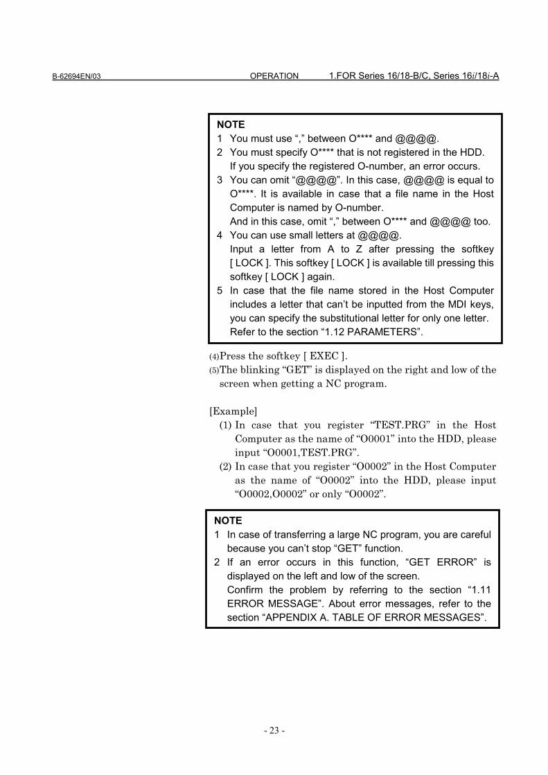
- 23 -
(4) Press the softkey [ EXEC ].(5) The blinking “GET” is displayed on the right and low of the
screen when getting a NC program.
[Example](1) In case that you register “TEST.PRG” in the Host
Computer as the name of “O0001” into the HDD, pleaseinput “O0001,TEST.PRG”.
(2) In case that you register “O0002” in the Host Computeras the name of “O0002” into the HDD, please input“O0002,O0002” or only “O0002”.
NOTE1 You must use “,” between O**** and @@@@.2 You must specify O**** that is not registered in the HDD.
If you specify the registered O-number, an error occurs.3 You can omit “@@@@”. In this case, @@@@ is equal to
O****. It is available in case that a file name in the HostComputer is named by O-number.And in this case, omit “,” between O**** and @@@@ too.
4 You can use small letters at @@@@.Input a letter from A to Z after pressing the softkey[ LOCK ]. This softkey [ LOCK ] is available till pressing thissoftkey [ LOCK ] again.
5 In case that the file name stored in the Host Computerincludes a letter that can’t be inputted from the MDI keys,you can specify the substitutional letter for only one letter.Refer to the section “1.12 PARAMETERS”.
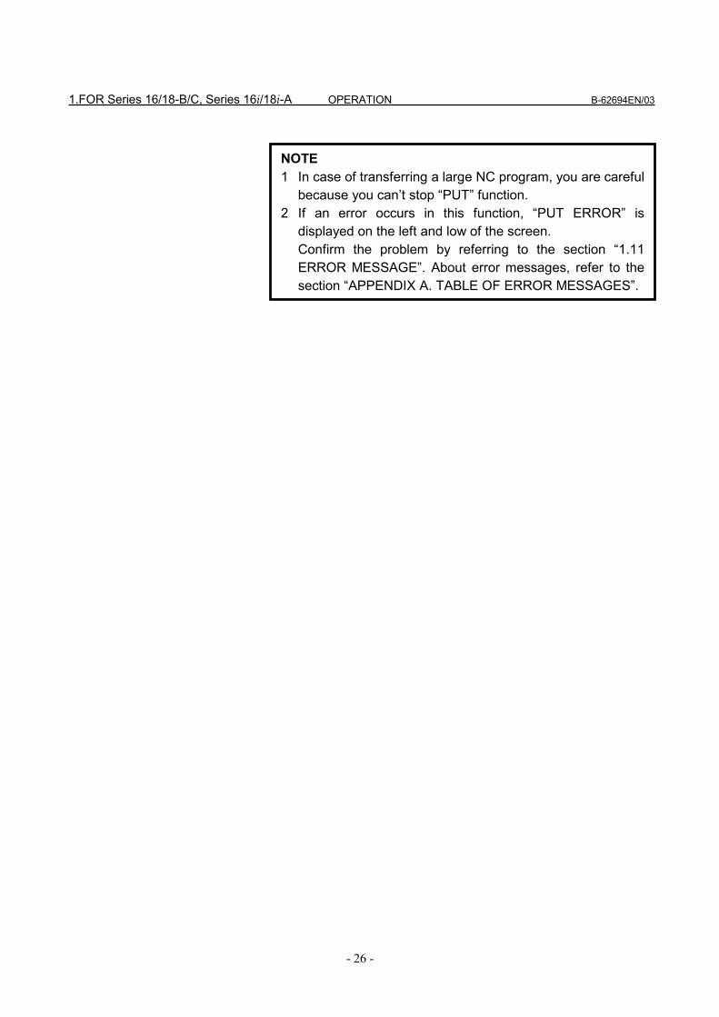
NOTE1 In case of transferring a large NC program, you are careful
because you can’t stop “GET” function.2 If an error occurs in this function, “GET ERROR” is
displayed on the left and low of the screen.Confirm the problem by referring to the section “1.11ERROR MESSAGE”. About error messages, refer to thesection “APPENDIX A. TABLE OF ERROR MESSAGES”.
1.FOR Series 16/18-B/C, Series 16i/18i-A OPERATION B-62694EN/03
- 24 -
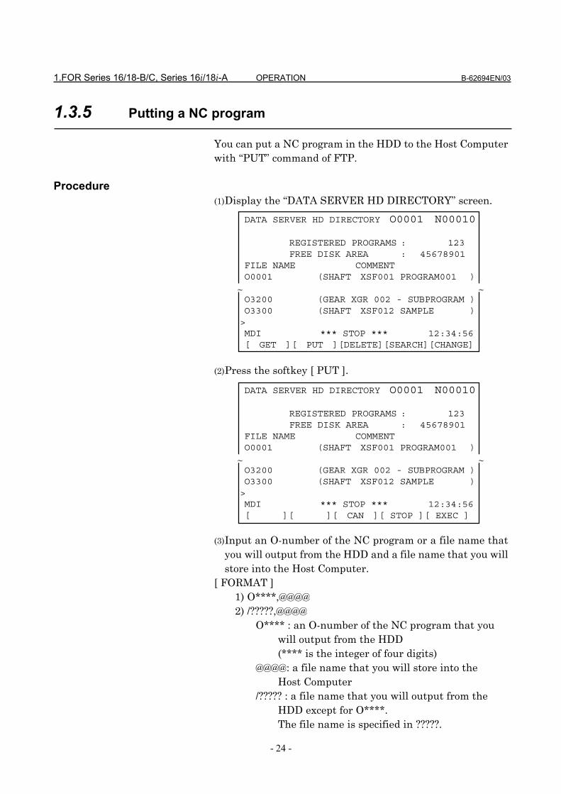
1.3.5 Putting a NC program
You can put a NC program in the HDD to the Host Computerwith “PUT” command of FTP.
Procedure(1) Display the “DATA SERVER HD DIRECTORY” screen. (2) Press the softkey [ PUT ]. (3) Input an O-number of the NC program or a file name that
you will output from the HDD and a file name that you willstore into the Host Computer.
[ FORMAT ] 1) O****,@@@@ 2) /?????,@@@@
O**** : an O-number of the NC program that you will output from the HDD (**** is the integer of four digits) @@@@: a file name that you will store into the Host Computer /????? : a file name that you will output from the HDD except for O****. The file name is specified in ?????.
DATA SERVER HD DIRECTORY O0001 N00010
REGISTERED PROGRAMS : 123FREE DISK AREA : 45678901
FILE NAME COMMENTO0001 (SHAFT XSF001 PROGRAM001 )
O3200 (GEAR XGR 002 - SUBPROGRAM )O3300 (SHAFT XSF012 SAMPLE )>MDI *** STOP *** 12:34:56[ ][ ][ CAN ][ STOP ][ EXEC ]
~ ~
DATA SERVER HD DIRECTORY O0001 N00010
REGISTERED PROGRAMS : 123FREE DISK AREA : 45678901
FILE NAME COMMENTO0001 (SHAFT XSF001 PROGRAM001 )
O3200 (GEAR XGR 002 - SUBPROGRAM )O3300 (SHAFT XSF012 SAMPLE )>MDI *** STOP *** 12:34:56[ GET ][ PUT ][DELETE][SEARCH][CHANGE]
~ ~

B-62694EN/03 OPERATION 1.FOR Series 16/18-B/C, Series 16i/18i-A
- 25 -
(4) Press the softkey [ EXEC ].(5) The blinking “PUT” is displayed on the right and low of the
screen when putting a NC program.
[Example](1) In case that you register “O0001” in the HDD as the
name of “TEST.PRG” into the Host Computer, pleaseinput “O0001,TEST.PRG”.
(2) In case that you register “O0002” in the HDD as thename of “O0002” into the Host Computer, please input“O0002,O0002” or only “O0002”.
(3) In case that you register “COMMON.RAM” in the HDDas the name of “COMMON.RAM” into the HostComputer, please input “/COMMON.RAM,COMMON.RAM” or only “/COMMON.RAM”.
NOTE1 You must use “,” between O****(/?????) and @@@@.2 You can omit “@@@@”. In this case, @@@@ is equal to
O**** or ?????. It is available in case that a file name in theHost Computer is named by the file name in the HDD( incase of NC program, named by O-number).And in this case, omit “,” between O****(/?????) and@@@@ too.
3 You must specify an O-number(O****) or a file(?????)registered in the HDD.If you specify an O-number or a file that is not registered inthe HDD, an error occurs.
4 You can use small letters at @@@@.Input a letter from A to Z after pressing the softkey[ LOCK ]. This softkey [ LOCK ] is available till pressing thissoftkey [ LOCK ] again.
5 In case that the file name storing into the Host Computerincludes a letter that can’t be inputted from the MDI keys,you can specify the substitutional letter for only one letter.Refer to the section “1.12 PARAMETERS”.
6 The format 2) will be used when you will transfer“COMMON.RAM” created in the “1.9 MAINTENANCE OFDATA SERVER”.
1.FOR Series 16/18-B/C, Series 16i/18i-A OPERATION B-62694EN/03
- 26 -
NOTE1 In case of transferring a large NC program, you are careful
because you can’t stop “PUT” function.2 If an error occurs in this function, “PUT ERROR” is
displayed on the left and low of the screen.Confirm the problem by referring to the section “1.11ERROR MESSAGE”. About error messages, refer to thesection “APPENDIX A. TABLE OF ERROR MESSAGES”.

B-62694EN/03 OPERATION 1.FOR Series 16/18-B/C, Series 16i/18i-A
- 27 -
1.3.6 List-Getting NC programs
You can get NC programs from the Host Computer with“GET” commnad of FTP according to the List-File stored inthe Host Computer.About the List-File, refer to the section “1.3.9 A format ofList-File”.
Procedure(1) Display the “DATA SERVER HD DIRECTORY” screen. (2) Press the continuous menu key, the following softkeys are
displayed. (3) Press the softkey [ L-GET ].
DATA SERVER HD DIRECTORY O0001 N00010
REGISTERED PROGRAMS : 123FREE DISK AREA : 45678901
FILE NAME COMMENTO0001 (SHAFT XSF001 PROGRAM001 )
O3200 (GEAR XGR 002 - SUBPROGRAM )O3300 (SHAFT XSF012 SAMPLE )>MDI *** STOP *** 12:34:56[ L-GET ][ L-PUT ][ L-DEL ][ ][ ]
~ ~
DATA SERVER HD DIRECTORY O0001 N00010
REGISTERED PROGRAMS : 123FREE DISK AREA : 45678901
FILE NAME COMMENTO0001 (SHAFT XSF001 PROGRAM001 )
O3200 (GEAR XGR 002 - SUBPROGRAM )O3300 (SHAFT XSF012 SAMPLE )>MDI *** STOP *** 12:34:56[ GET ][ PUT ][DELETE][SEARCH][CHANGE]
~ ~
DATA SERVER HD DIRECTORY O0001 N00010
REGISTERED PROGRAMS : 123FREE DISK AREA : 45678901
FILE NAME COMMENTO0001 (SHAFT XSF001 PROGRAM001 )
O3200 (GEAR XGR 002 - SUBPROGRAM )O3300 (SHAFT XSF012 SAMPLE )>MDI *** STOP *** 12:34:56[ ][ ][ CAN ][ STOP ][ EXEC ]
~ ~
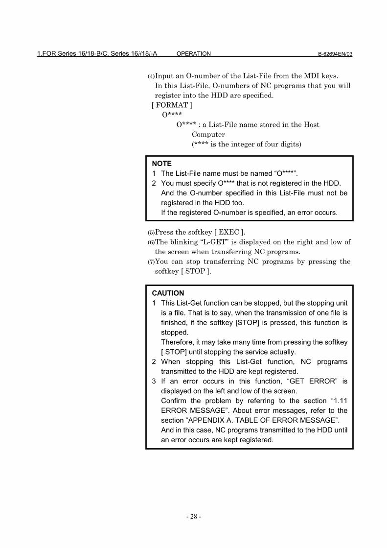
1.FOR Series 16/18-B/C, Series 16i/18i-A OPERATION B-62694EN/03
- 28 -
(4) Input an O-number of the List-File from the MDI keys.In this List-File, O-numbers of NC programs that you willregister into the HDD are specified.
[ FORMAT ] O****
O**** : a List-File name stored in the Host Computer (**** is the integer of four digits)
(5) Press the softkey [ EXEC ].(6) The blinking “L-GET” is displayed on the right and low of
the screen when transferring NC programs.(7) You can stop transferring NC programs by pressing the
softkey [ STOP ].
NOTE1 The List-File name must be named “O****”.2 You must specify O**** that is not registered in the HDD.
And the O-number specified in this List-File must not beregistered in the HDD too.If the registered O-number is specified, an error occurs.
CAUTION1 This List-Get function can be stopped, but the stopping unit
is a file. That is to say, when the transmission of one file isfinished, if the softkey [STOP] is pressed, this function isstopped.Therefore, it may take many time from pressing the softkey[ STOP] until stopping the service actually.
2 When stopping this List-Get function, NC programstransmitted to the HDD are kept registered.
3 If an error occurs in this function, “GET ERROR” isdisplayed on the left and low of the screen.Confirm the problem by referring to the section “1.11ERROR MESSAGE”. About error messages, refer to thesection “APPENDIX A. TABLE OF ERROR MESSAGE”.And in this case, NC programs transmitted to the HDD untilan error occurs are kept registered.

B-62694EN/03 OPERATION 1.FOR Series 16/18-B/C, Series 16i/18i-A
- 29 -
NOTE1 In this function, the specified List-File is transferred from
the Host Computer to the HDD too.First, the List-File is transferred from the Host Computer tothe HDD, then check the contents of this List-File.Afterward transfer the NC programs specified in this List-File in order.And, when checking the contents of the List-File, if theircontents are mistaken , the specified NC program in theList-File exists in the HDD or the specified NC program isused by other services, this function terminates abnormallyand the List-File is deleted.

1.FOR Series 16/18-B/C, Series 16i/18i-A OPERATION B-62694EN/03
- 30 -
1.3.7 List-Putting NC programs
You can put NC programs into the Host Computer with“PUT” commnad of FTP according to the List-File stored inthe HDD.About the List-File, refer to the section “1.3.9 A format ofList-File”.
Procedure(1) Display the “DATA SERVER HD DIRECTORY” screen. (2) Press the continuous menu key, the following softkeys are
displayed. (3) Press the softkey [ L-PUT ].
DATA SERVER HD DIRECTORY O0001 N00010
REGISTERED PROGRAMS : 123FREE DISK AREA : 45678901
FILE NAME COMMENTO0001 (SHAFT XSF001 PROGRAM001 )
O3200 (GEAR XGR 002 - SUBPROGRAM )O3300 (SHAFT XSF012 SAMPLE )>MDI *** STOP *** 12:34:56[ L-GET ][ L-PUT ][ L-DEL ][ ][ ]
~ ~
DATA SERVER HD DIRECTORY O0001 N00010
REGISTERED PROGRAMS : 123FREE DISK AREA : 45678901
FILE NAME COMMENTO0001 (SHAFT XSF001 PROGRAM001 )
O3200 (GEAR XGR 002 - SUBPROGRAM )O3300 (SHAFT XSF012 SAMPLE )>MDI *** STOP *** 12:34:56[ GET ][ PUT ][DELETE][SEARCH][CHANGE]
~ ~
DATA SERVER HD DIRECTORY O0001 N00010
REGISTERED PROGRAMS : 123FREE DISK AREA : 45678901
FILE NAME COMMENTO0001 (SHAFT XSF001 PROGRAM001 )
O3200 (GEAR XGR 002 - SUBPROGRAM )O3300 (SHAFT XSF012 SAMPLE )>MDI *** STOP *** 12:34:56[ ][ ][ CAN ][ STOP ][ EXEC ]
~ ~

B-62694EN/03 OPERATION 1.FOR Series 16/18-B/C, Series 16i/18i-A
- 31 -
(4) Input an O-number of the List-File from the MDI keys.In this List-File, O-numbers of NC programs that you willregister into the Host Computer are specified.
[ FORMAT ] O****
O**** : a List-File name stored in the HDD (**** is the integer of four digits)
(5) Press the softkey [ EXEC ].(6) The blinking “L-PUT” is displayed on the right and low of
the screen when transferring NC programs.(7) You can stop transferring NC programs by pressing the
softkey [ STOP ].
NOTE1 The List-File name must be named “O****”.2 You must specify O**** that is registered in the HDD.
And the O-number specified in this List-File must beregistered in the HDD too.If the specified O-number doesn’t exist in the HDD, anerror occurs.
CAUTION1 This List-Put function can be stopped, but the stopping unit
is a file. That is to say, when the transmission of one file isfinished, if the softkey [STOP] is pressed, this function isstopped.Therefore, it may take many time from pressing the softkey[ STOP] until stopping the service actually.
2 When stopping this List-Put function, NC programstransmitted to the Host Computer are kept registered.
3 If an error occurs in this function, “PUT ERROR” isdisplayed on the left and low of the screen.Confirm the problem by referring to the section “1.11ERROR MESSAGE”. About error messages, refer to thesection “APPENDIX A. TABLE OF ERROR MESSAGES”.And in this case, NC programs transmitted to the HostComputer until an error occurs are kept registered.

1.FOR Series 16/18-B/C, Series 16i/18i-A OPERATION B-62694EN/03
- 32 -
NOTE1 In this function, the specified List-File is transferred from
the HDD to the Host Computer too.First, check the contents of the specified List-File, then thisList-File is transferred into the Host Computer. Afterwardtransfer the NC programs specified in this List-File in order.And, when checking the contents of the List-File, if thecontents are mistaken , the specified NC program in theList-File doesn’t exist in the HDD or the specified NCprogram is used by other services, this function terminatesabnormally.

B-62694EN/03 OPERATION 1.FOR Series 16/18-B/C, Series 16i/18i-A
- 33 -
1.3.8 List-Deleting NC programs
You can delete NC programs from the HDD according to theList-File stored in the HDD.About the List-File, refer to the section “1.3.9 A format ofList-File”.
Procedure(1) Display the “DATA SERVER HD DIRECTORY” screen. (2) Press the continuous menu key, the following softkeys are
displayed. (3) Press the softkey [ L-DEL ].
DATA SERVER HD DIRECTORY O0001 N00010
REGISTERED PROGRAMS : 123FREE DISK AREA : 45678901
FILE NAME COMMENTO0001 (SHAFT XSF001 PROGRAM001 )
O3200 (GEAR XGR 002 - SUBPROGRAM )O3300 (SHAFT XSF012 SAMPLE )>MDI *** STOP *** 12:34:56[ L-GET ][ L-PUT ][ L-DEL ][ ][ ]
~ ~
DATA SERVER HD DIRECTORY O0001 N00010
REGISTERED PROGRAMS : 123FREE DISK AREA : 45678901
FILE NAME COMMENTO0001 (SHAFT XSF001 PROGRAM001 )
O3200 (GEAR XGR 002 - SUBPROGRAM )O3300 (SHAFT XSF012 SAMPLE )>MDI *** STOP *** 12:34:56[ GET ][ PUT ][DELETE][SEARCH][CHANGE]
~ ~
DATA SERVER HD DIRECTORY O0001 N00010
REGISTERED PROGRAMS : 123FREE DISK AREA : 45678901
FILE NAME COMMENTO0001 (SHAFT XSF001 PROGRAM001 )
O3200 (GEAR XGR 002 - SUBPROGRAM )O3300 (SHAFT XSF012 SAMPLE )>MDI *** STOP *** 12:34:56[ ][ ][ CAN ][ STOP ][ EXEC ]
~ ~

1.FOR Series 16/18-B/C, Series 16i/18i-A OPERATION B-62694EN/03
- 34 -
(4) Input an O-number of the List-File from the MDI keys.In this List-File, O-numbers of NC programs that you willdelete from the HDD are specified.
[ FORMAT ] O****
O**** : a List-File name stored in the HDD (**** is the integer of four digits)
(5) Press the softkey [ EXEC ].(6) The blinking “L-DEL” is displayed on the right and low of
the screen when deleting NC programs.(7) You can stop deleting NC programs by pressing the softkey
[ STOP ].
NOTE1 The List-File name must be named “O****”.2 You must specify O**** that is registered in the HDD.
But the O-number specified in this List-File may not beregistered in the HDD.If the specified O-number doesn’t exist in the HDD, ignorethis file.
CAUTION1 When stopping this List-Delete function, deleted NC
programs from the HDD can’t be recovered.2 If an error occurs in this function, “DELETE ERROR” is
displayed on the left and low of the screen.Confirm the problem by referring to the section “1.11ERROR MESSAGE”. About error messages, refer to thesection “APPENDIX A. TABLE OF ERROR MESSAGES”.And in this case, deleted NC programs from the HDD can’tbe recovered.
NOTE1 In this function, the specified List-File is deleted from the
HDD too.First, check the contents of the specified List-File, thendelete the NC programs specified in this List-File in order.Afterward this List-File is deleted from the HDD.And, when checking the contents of the List-File, if thecontents are mistaken or the specified NC program is usedby other services, this function terminates abnormally.

B-62694EN/03 OPERATION 1.FOR Series 16/18-B/C, Series 16i/18i-A
- 35 -
1.3.9 A format of List-File
A List-File that is used by List-Get,List-Put,List-Deletefunctions must be composed as follows.
(1) The top of List-File must always be a “%”.( “;” means EOB(End Of Block). LF, CR-LF and LF-CR-CR can be used as EOB code. But use the same EOBcode in one List-File.)
(2) The next block must be an O-number. Please write thesame O-number as the file name.And you can write a comment only latter than this O-number up to EOB.
(3) Specify the O-number of NC program that you want tooperate. But in this case, the top of the file name “O”must be changed into “N”.In the above case, the NC programs of O0111, O0222,O0333,...,and O0999 are transferred or deleted in order.On the O-number in the List-File, NC program numbershorter than 4 digits is compensated for 4 digitsautomatically by the Data Server’s software.
(4) The end of List-File must always be a “%”.
These List-Get, List-Put and List-Delete functions are usefulfor managing NC programs as a group.And the place where the List-File is prepared is differentaccording to each function.In case of the List-Get function, the List-File is prepared inthe Host Computer because the NC programs that you wantto transfer exist in the Host Computer.In case of List-Put and List-Delete functions, the List-File isprepared in the HDD because the NC programs that youwant to transfer or delete exist in the HDD.
% ;O0001(COMMENT) ;N111 ;N222 ;N333 ;
::
N999 ;%

1.FOR Series 16/18-B/C, Series 16i/18i-A OPERATION B-62694EN/03
- 36 -
1.3.10 A format of NC program
A format of NC program prepared in the Host Computerobeys the format described in the CNC’s manual.Describe it briefly as follows.
(1) The top of NC program must be “%”(Tape start).And if necessary, you can enter a comment up to firstEOB code(Program start).
(2) The next block is an O-number.When you register this NC program into the HDD,please surely name the same O-number as the file name.If the O-number in the NC program is different from theO-number of the file name, the O-number of the filename will be used.
(3) “;” placed on the end of each line means EOB (End OfBlock).This EOB code is LF(hexadecimal code:0A) or LF-CR-CR(hexadecimal code:0A-0D-0D).
(4) The end of NC program always must end with a “M-code ; %”.
(5) If you want to operate “binary input operation”, pleaseinsert binary data for “binary input operation” in “:”parts of the above figure.About the detail of “binary input operation”, please referto the each CNC’s operator’s manual.
% TITLE ;O0001 (COMMENT) ;
:::
M30 ;%
WARNINGIf you prepare the NC program contrary to the aboveformat in the Host Computer, the CNC may run unexpectlywhen this NC program is running.So, you prepare the NC program in the Host Computermost carefully.

B-62694EN/03 OPERATION 1.FOR Series 16/18-B/C, Series 16i/18i-A
- 37 -
1.4 CALLING A SUBPROGRAM WITH M198
When the subprogram is called by M198 code in mainprogram stored in the memory of CNC, the CNC reads thesubprogram from the HDD.
Format of M198 code in the main program(1) In case of Series 15 tape format M198P****L@@@@;
**** : the integer of four digits that expresses the O-number
@@@@ : repeat time (from 1 to 9999). When it is omitted, it is supposed to be 1.
(2) In case of other tape formats M198P@@@@****;
**** : the integer of four digits that expresses the O-number
(You must set the integer of four digits) @@@@ : repeat time (from 1 to 9999)
The other item related to M198 code is based on “subprogramcall function” in external input/output devices.Refer to the CNC’s manual in detail.
[Example]In case of Series 15 tape format
Main program Sub program(the memory of CNC) (HDD of Data Server)
%;O1234(SUB PROGRAM);
::::::::
M99;%
%;O0001(MAIN PROGRAM);
:::
M198P1234;::::
M30;%

1.FOR Series 16/18-B/C, Series 16i/18i-A OPERATION B-62694EN/03
- 38 -
NOTE1 You must set “5” on the NC parameter of I/O Channel
(No.0020) in order to use this function.2 You can not execute this function together with “1.5
REGISTERING A NC PROGRAM”, “1.6 OUTPUTTING ANC PROGRAM” or “1.7 DNC OPERATION”.
3 You can not call the subprogram in the HDD again in thecalled subprogram on this function, but you can call thesubprogram in the memory of CNC.
4 The Data Server is equal to other external input/outputdevices from view point of a CNC.So, the limitation related to “subprogram call function” forthe Data Server is equal to the one for other externalinput/output devices.

B-62694EN/03 OPERATION 1.FOR Series 16/18-B/C, Series 16i/18i-A
- 39 -
1.5 REGISTERING A NC PROGRAM
You can register a NC program in the HDD to the memory ofthe CNC.
Procedure(1) Change the mode of the CNC into “EDIT” mode (in case of
foreground operation).(2) Press the function key in order to display the
“PROGRAM” screen.(3) Input an O-number of the NC program that you will
register from the HDD to the memory of the CNC.(4) Press the softkey [ READ ].(5) Press the softkey [ EXEC ].(6) The blinking “INPUT” is displayed on the right and low of
the screen when registering a NC program.
PPPPRRRROOOOGGGG
CAUTION1 When you register a NC program to the memory of the
CNC, please take care of the O-number of the registeredNC program in the CNC. In case that the NC parameterNo.3201 #2(REP) is equal to 1, if your specified O-numberexists in the CNC, the old NC program is overwritten.And if the NC parameter No.3201 #0(RDL) is equal to 1,register the specified NC program after deleting all NCprograms in the memory of the CNC.
2 If you use the buffer mode ( See “1.10 BUFFER MODE” ),this function runs as it is the buffer mode. Therefore, theData Server software understands the specified O-numberas the list of files and gets divided NC programs from theHost Computer. So, you must not use this function on thebuffer mode.
NOTE1 You must set “5” on the NC parameter of I/O Channel
(No.0020) in order to use this function.2 You can not execute this function together with “1.4
CALLING A SUBPROGRAM WITH M198”, “1.6OUTPUTTING A NC PROGRAM” or “1.7 DNCOPERATION”.
3 You can execute this function under background operation.Please refer to the CNC’s manual in detail.

1.FOR Series 16/18-B/C, Series 16i/18i-A OPERATION B-62694EN/03
- 40 -
1.6 OUTPUTTING A NC PROGRAM
You can output a NC program in the memory of CNC to theHDD.
Procedure(1) Change the mode of CNC into “EDIT” mode (in case of
foreground operation).(2) Press the function key in order to display the
“PROGRAM” screen.(3) Input a O-number of the NC program that you will output
from the memory of CNC to the HDD.(4) Press the softkey [PUNCH].(5) Press the softkey [ EXEC ].(6) The blinking “OUTPUT” is displayed on the right and low
of the screen when outputting a NC program.
PPPPRRRROOOOGGGG
NOTE1 You must set “5” on the NC parameter of I/O Channel
(No.0020) in order to use this function.2 You can not execute this function together with “1.4
CALLING A SUBPROGRAM WITH M198”, “1.5REGISTERING A NC PROGRAM” or “1.7 DNCOPERATION”.
3 You can execute this function under background operation.Please refer to the CNC’s manual in detail.
4 If you specify the NC program that already exists in theHDD, an error occurs.Please change O-number in the memory of CNC or deletea NC program from the HDD.
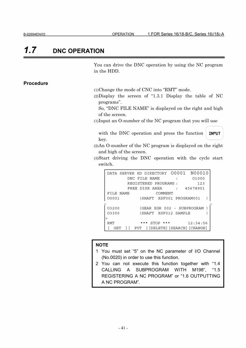
B-62694EN/03 OPERATION 1.FOR Series 16/18-B/C, Series 16i/18i-A
- 41 -
1.7 DNC OPERATION
You can drive the DNC operation by using the NC programin the HDD.
Procedure(1) Change the mode of CNC into “RMT” mode.(2) Display the screen of “1.3.1 Display the table of NC
programs”.So, “DNC FILE NAME” is displayed on the right and highof the screen.
(1) Input an O-number of the NC program that you will use
with the DNC operation and press the functionkey.
(2) An O-number of the NC program is displayed on the rightand high of the screen.
(3) Start driving the DNC operation with the cycle startswitch.
INPUTINPUTINPUTINPUT
DATA SERVER HD DIRECTORY O0001 N00010DNC FILE NAME : O1000REGISTERED PROGRAMS : 123FREE DISK AREA : 45678901
FILE NAME COMMENTO0001 (SHAFT XSF001 PROGRAM001 )
O3200 (GEAR XGR 002 - SUBPROGRAM )O3300 (SHAFT XSF012 SAMPLE )>RMT *** STOP *** 12:34:56[ GET ][ PUT ][DELETE][SEARCH][CHANGE]
~ ~
NOTE1 You must set “5” on the NC parameter of I/O Channel
(No.0020) in order to use this function.2 You can not execute this function together with “1.4
CALLING A SUBPROGRAM WITH M198”, “1.5REGISTERING A NC PROGRAM” or “1.6 OUTPUTTINGA NC PROGRAM”.
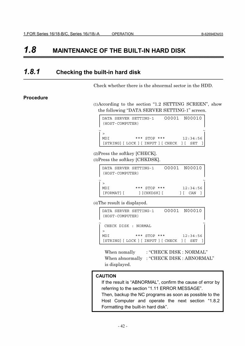
1.FOR Series 16/18-B/C, Series 16i/18i-A OPERATION B-62694EN/03
- 42 -
1.8 MAINTENANCE OF THE BUILT-IN HARD DISK
1.8.1 Checking the built-in hard disk
Check whether there is the abnormal sector in the HDD.
Procedure(1) According to the section “1.2 SETTING SCREEN”, show
the following “DATA SERVER SETTING-1” screen. (2) Press the softkey [CHECK].(3) Press the softkey [CHKDSK]. (4) The result is displayed.
When nomally : “CHECK DISK : NORMAL”When abnormally : “CHECK DISK : ABNORMAL”is displayed.
DATA SERVER SETTING-1 O0001 N00010(HOST-COMPUTER)
>MDI *** STOP *** 12:34:56[STRING][ LOCK ][ INPUT ][ CHECK ][ SET ]
~ ~
DATA SERVER SETTING-1 O0001 N00010(HOST-COMPUTER)
>MDI *** STOP *** 12:34:56[FORMAT][ ][CHKDSK][ ][ CAN ]
~ ~
CAUTIONIf the result is “ABNORMAL”, confirm the cause of error byreferring to the section “1.11 ERROR MESSAGE”.Then, backup the NC programs as soon as possible to theHost Computer and operate the next section “1.8.2Formatting the built-in hard disk”.
DATA SERVER SETTING-1 O0001 N00010(HOST-COMPUTER)
CHECK DISK : NORMAL>MDI *** STOP *** 12:34:56[STRING][ LOCK ][ INPUT ][ CHECK ][ SET ]
~ ~

B-62694EN/03 OPERATION 1.FOR Series 16/18-B/C, Series 16i/18i-A
- 43 -
1.8.2 Formatting the built-in hard disk
Initialize the built-in hard disk.
Procedure(1) According to the section “1.2 SETTING SCREEN”, show
the following “DATA SERVER SETTING-1” screen. (2) Press the softkey [CHECK].(3) Press the softkey [FORMAT]. (4) Press the softkey [ EXEC ]. (5) The message “HARD DISK FORMAT?” is displayed on the
screen, press the softkey [ EXEC ] again. (6) The blinking “DISK FORMAT” is displayed on the low of
the screen when initializing the HDD.
DATA SERVER SETTING-1 O0001 N00010(HOST-COMPUTER)
>MDI *** STOP *** 12:34:56[STRING][ LOCK ][ INPUT ][ CHECK ][ SET ]
~ ~
DATA SERVER SETTING-1 O0001 N00010(HOST-COMPUTER)
>MDI *** STOP *** 12:34:56[FORMAT][ ][CHKDSK][ ][ CAN ]
~ ~
DATA SERVER SETTING-1 O0001 N00010(HOST-COMPUTER)
>MDI *** STOP *** 12:34:56[FORMAT][ ][CHKDSK][ ][ CAN ]
~ ~
DATA SERVER SETTING-1 O0001 N00010(HOST-COMPUTER)
>MDI *** STOP *** 12:34:56[FORMAT][ ][CHKDSK][ ][ CAN ]
~ ~
DATA SERVER SETTING-1 O0001 N00010(HOST-COMPUTER)
>MDI *** STOP *** 12:34:56[ ][ ][ ][ CAN ][ EXEC ]
~ ~
DATA SERVER SETTING-1 O0001 N00010(HOST-COMPUTER)
>MDI *** STOP *** 12:34:56[ ][ ][ ][ CAN ][ EXEC ]
~ ~
DATA SERVER SETTING-1 O0001 N00010(HOST-COMPUTER)
HARD DISK FORMAT?>MDI *** STOP *** 12:34:56[ ][ ][ EXEC ][ CAN ][ ]
~ ~
NOTEThese maintenance functions can’t be operated togetherwith other functions.

1.FOR Series 16/18-B/C, Series 16i/18i-A OPERATION B-62694EN/03
- 44 -
1.9 MAINTENANCE OF DATA SERVER
If the trouble occurs at the Data Server function, thecontents of COMMON RAM for the interface between CNCand Data Server can be saved into a file in order to examineit.This file is transferred to the Host Computer by using “1.3.5Putting a NC program” and the inside status of the DataServer is checked by this file.
Procedure(1) Press the function key. (2) If the softkey [DS-MNT] isn’t displayed, press the
continuous menu key several times.(3) Press the softkey [DS-MNT], and display the
“MAINTENANCE OF DATA SERVER” screen.
[Reference]Each item means as follows.These items are used when transferring a NCprogram from Data Server to the CNC. Therefore,other services are not related to these.(A) EMPTY COUNTER
This item shows the counter to check that thebuffer is empty during the download of the NCprograms.When power on, initilize this counter. Afterward,when the buffer is empty, increase this counter.
(B) TOTAL SIZEThis item shows the total byte size of one NCprogram, when transfer a NC program from the
SSSSYYYYSSSSTTTTEMEMEMEM
MAINTENANCE OF DATA SERVER O0001 N00010
EMPTY COUNTER 0TOTAL SIZE 9,999,999,999READ POINTER 99,999WRITE POINTER 99,999
>MDI *** STOP *** 12:34:56[ SAVE ][ ][ ][ ][ ]
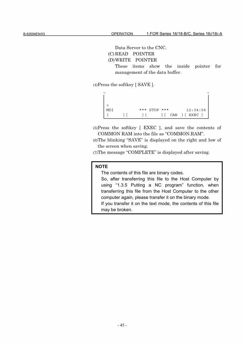
B-62694EN/03 OPERATION 1.FOR Series 16/18-B/C, Series 16i/18i-A
- 45 -
Data Server to the CNC.(C) READ POINTER(D) WRITE POINTER
These items show the inside pointer formanagement of the data buffer.
(4) Press the softkey [ SAVE ]. (5) Press the softkey [ EXEC ], and save the contents of
COMMON RAM into the file as “COMMON.RAM”.(6) The blinking “SAVE” is displayed on the right and low of
the screen when saving.(7) The message “COMPLETE” is displayed after saving.
>MDI *** STOP *** 12:34:56[ ][ ][ ][ CAN ][ EXEC ]
~ ~
NOTEThe contents of this file are binary codes.So, after transferring this file to the Host Computer byusing “1.3.5 Putting a NC program” function, whentransferring this file from the Host Computer to the othercomputer again, please transfer it on the binary mode.If you transfer it on the text mode, the contents of this filemay be broken.

1.FOR Series 16/18-B/C, Series 16i/18i-A OPERATION B-62694EN/03
- 46 -
1.10 BUFFER MODE (OPTIONAL FUNCTION)
The software of the Data Server can operate on theSTORAGE mode or the BUFFER mode. The software on thestorage mode can do the services mentioned in the previoussections, but can’t control a larger NC program than the sizeof the built-in hard disk.The buffer mode is used to control a larger NC program thanthe size of the built-in hard disk. On this buffer mode, thebuilt-in hard disk is divided into two areas(area A, areaB)virtually. A part of a NC program in one area of the built-inhard disk is supplied to the CNC and a continuous part of theNC program is got into another area in the built-in hard diskby using FTP at the same time. A larger NC program thanthe size of the built-in hard disk can be controlled byrepeating the above operation.But you must divide a larger NC program than the size of thebuilt-in hard disk into some files with about 35MB in theHost Computer in advance. Now, there are some kinds ofbuilt-in hard disk, but we recommend that the divided size isabout 35MB. Because you can divide the NC program intothe size larger than 35MB, but if so, more time is necessaryto get the first file from the Host Computer.

B-62694EN/03 OPERATION 1.FOR Series 16/18-B/C, Series 16i/18i-A
- 47 -
1.10.1 How to change the mode
When using the buffer mode, it is necessary to change themode from the storage mode to the buffer mode.
Procedure(1) Press the function key. (2) If the softkey [DS-MOD] isn’t displayed, press the
continuous menu key several times.(3) Press the softkey [DS-MOD], and “DATA SERVER MODE”
screen is displayed.The current mode is displayed on the screen.(explain the example to change the mode from the storagemode to the buffer mode as follows)
(4) Press the softkey [ MODE ]. (5) Press the softkey [ EXEC ], so that the mode is changed.
If the mode is changed, all NC programs in the HDD willbe deleted.
(6) The blinking “MODE” is displayed on the right and low of
SSSSYYYYSSSSTTTTEMEMEMEM
DATA SERVER MODE O0001 N00010
STORAGE MODE
>MDI *** STOP *** 12:34:56[ ][ ][ ][ MODE ][ ]
DATA SERVER MODE O0001 N00010
STORAGE MODE
IF YOU CHANGE THE MODE,ALL NC PROGRAMS IN HDD WILL BE LOST.
CHANGE THE MODE?MDI *** STOP *** 12:34:56[ ][ ][ ][ CAN ][ EXEC ]
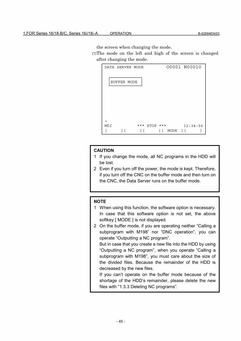
1.FOR Series 16/18-B/C, Series 16i/18i-A OPERATION B-62694EN/03
- 48 -
the screen when changing the mode.(7) The mode on the left and high of the screen is changed
after changing the mode.
DATA SERVER MODE O0001 N00010
BUFFER MODE
>MDI *** STOP *** 12:34:56[ ][ ][ ][ MODE ][ ]
CAUTION1 If you change the mode, all NC programs in the HDD will
be lost.2 Even if you turn off the power, the mode is kept. Therefore,
if you turn off the CNC on the buffer mode and then turn onthe CNC, the Data Server runs on the buffer mode.
NOTE1 When using this function, the software option is necessary.
In case that this software option is not set, the abovesoftkey [ MODE ] is not displayed.
2 On the buffer mode, if you are operating neither “Calling asubprogram with M198” nor “DNC operation”, you canoperate “Outputting a NC program”.But in case that you create a new file into the HDD by using“Outputting a NC program”, when you operate “Calling asubprogram with M198”, you must care about the size ofthe divided files. Because the remainder of the HDD isdecreased by the new files.If you can’t operate on the buffer mode because of theshortage of the HDD’s remainder, please delete the newfiles with “1.3.3 Deleting NC programs”.
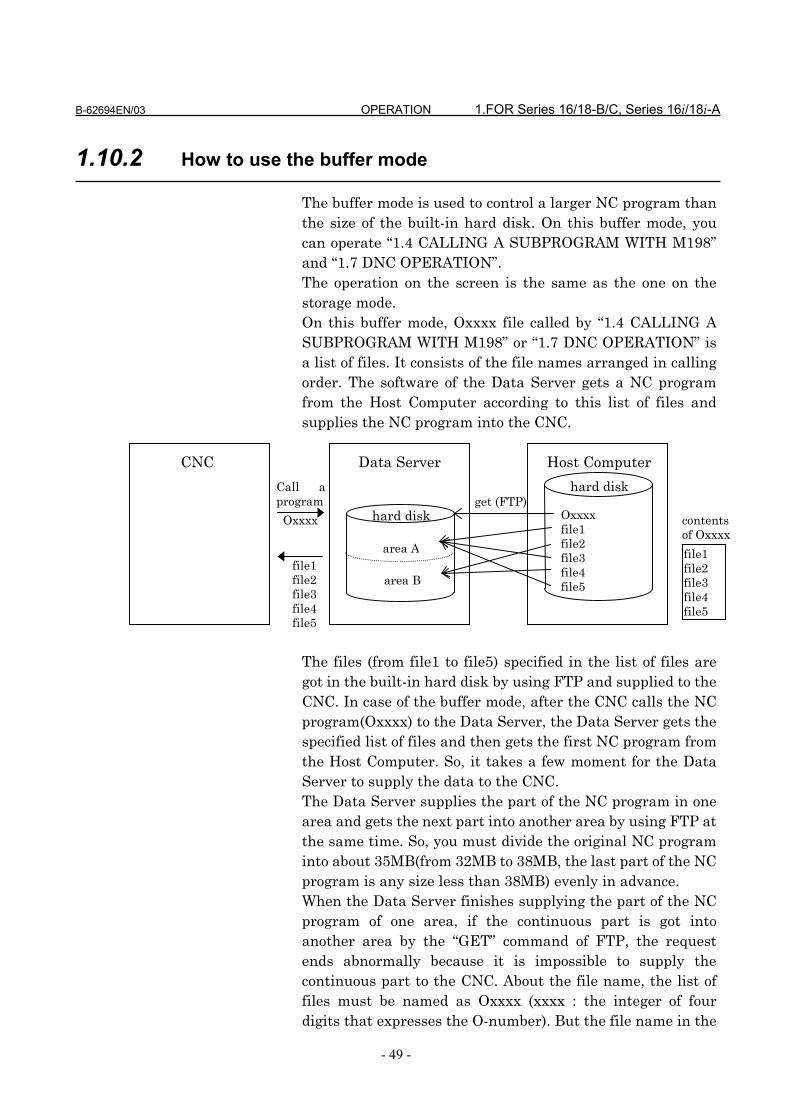
B-62694EN/03 OPERATION 1.FOR Series 16/18-B/C, Series 16i/18i-A
- 49 -
1.10.2 How to use the buffer mode
The buffer mode is used to control a larger NC program thanthe size of the built-in hard disk. On this buffer mode, youcan operate “1.4 CALLING A SUBPROGRAM WITH M198”and “1.7 DNC OPERATION”.The operation on the screen is the same as the one on thestorage mode.On this buffer mode, Oxxxx file called by “1.4 CALLING ASUBPROGRAM WITH M198” or “1.7 DNC OPERATION” isa list of files. It consists of the file names arranged in callingorder. The software of the Data Server gets a NC programfrom the Host Computer according to this list of files andsupplies the NC program into the CNC.
CNC Data Server Host Computer
The files (from file1 to file5) specified in the list of files aregot in the built-in hard disk by using FTP and supplied to theCNC. In case of the buffer mode, after the CNC calls the NCprogram(Oxxxx) to the Data Server, the Data Server gets thespecified list of files and then gets the first NC program fromthe Host Computer. So, it takes a few moment for the DataServer to supply the data to the CNC.The Data Server supplies the part of the NC program in onearea and gets the next part into another area by using FTP atthe same time. So, you must divide the original NC programinto about 35MB(from 32MB to 38MB, the last part of the NCprogram is any size less than 38MB) evenly in advance.When the Data Server finishes supplying the part of the NCprogram of one area, if the continuous part is got intoanother area by the “GET” command of FTP, the requestends abnormally because it is impossible to supply thecontinuous part to the CNC. About the file name, the list offiles must be named as Oxxxx (xxxx : the integer of fourdigits that expresses the O-number). But the file name in the
contentsof Oxxxx
file1file2file3file4file5
hard diskget (FTP)
Call aprogram
Oxxxx Oxxxxfile1file2file3file4file5
file1file2file3file4file5
hard disk
area A
area B
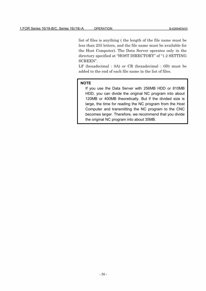
1.FOR Series 16/18-B/C, Series 16i/18i-A OPERATION B-62694EN/03
- 50 -
list of files is anything ( the length of the file name must beless than 255 letters, and the file name must be available forthe Host Computer). The Data Server operates only in thedirectory specified at “HOST DIRECTORY” of “1.2 SETTINGSCREEN”.LF (hexadecimal : 0A) or CR (hexadecimal : 0D) must beadded to the end of each file name in the list of files.
NOTEIf you use the Data Server with 256MB HDD or 810MBHDD, you can divide the original NC program into about120MB or 400MB theoretically. But if the divided size islarge, the time for reading the NC program from the HostComputer and transmitting the NC program to the CNCbecomes larger. Therefore, we recommend that you dividethe original NC program into about 35MB.

B-62694EN/03 OPERATION 1.FOR Series 16/18-B/C, Series 16i/18i-A
- 51 -
1.10.3 How to divide a large NC program
If you will operate the Data Server on the buffer mode, youmust divide a large NC program into some files with about35MB in the Host Computer and create a file that consists ofthe file name of the divided files in advance as follows.
Example)In case that a large NC program is divided into three partswithout separating one block
An original NC program is divided into three parts like theabove. And all the divided files are specified in the file asO1234 in order.
NOTEIn case of the above example, a NC program is dividedwithout separating one block. But it is possible that a NCprogram is divided with separating one block, provided thatyou don’t add the unnecessary letter after the bottom ofeach file.
%
O1234(SAMPLE);・・・
X1.Y1.Z1.;
%
O1234(SAMPLE);・・・
X1.Y1.Z1.;
X2.Y2.Z2.;・・・
X3.Y3.Z3.;
X4.Y4.Z4.;・・・
M30;
%
X2.Y2.Z2.;・・・
X3.Y3.Z3.;
X4.Y4.Z4.;・・・
M30;
%
file1
file2
file3
file1
an original NC program
divide intothree parts
the list of files
file2
file3
O1234
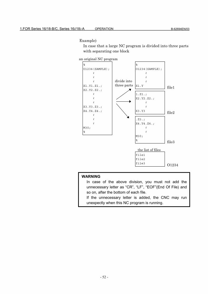
1.FOR Series 16/18-B/C, Series 16i/18i-A OPERATION B-62694EN/03
- 52 -
Example)In case that a large NC program is divided into three partswith separating one block
WARNINGIn case of the above division, you must not add theunnecessary letter as “CR”, “LF”, “EOF”(End Of File) andso on, after the bottom of each file.If the unnecessary letter is added, the CNC may rununexpectly when this NC program is running.
%
O1234(SAMPLE);・・・
X1.Y
%
O1234(SAMPLE);・・・
X1.Y1.Z1.;
X2.Y2.Z2.;・・・
X3.Y3.Z3.;
X4.Y4.Z4.;・・・
M30;
%
1.Z1.;
X2.Y2.Z2.;・・
X3.Y3
.Z3.;
X4.Y4.Z4.;・・
M30;
%
file1
file2
file3
file1
an original NC program
divide intothree parts
the list of files
file2
file3
O1234

B-62694EN/03 OPERATION 1.FOR Series 16/18-B/C, Series 16i/18i-A
- 53 -
1.11 ERROR MESSAGE
If an error occurs in the Data Server function, the errordescription is displayed on the following error messagescreen for the Data Server function. So, if an error occurs, seethis screen and confirm the description.
Procedure(1) Press the function key. (2) When the softkey [DS-MSG] isn’t displayed, press the
continuous menu key.(3) Press the softkey [DS-MSG], so that the following screen is
displayed.The last error message is shown at the top of screen.
MESSAGEMESSAGEMESSAGEMESSAGE
DATA SERVER MESSAGE-1 O0001 N00010
--------------------------- 940710 1134------------------ 940510 1649---------------------- 940327 0956
----------------------- 940312 1202
>MDI *** STOP *** 12:34:56[DS-MSG][ ][ ][ ][ ]
DATA SERVER MESSAGE-2 O0001 N00010
DATA-SERVER SYSTEM ROM nnnn [x] yy/mm/ddCPU : GENERAL PROTECTION
0000 0000 0000 0000 0000 0000 0000 000000000000 00000000 00000000 0000000000000000 00000000 00000000 0000000000000000 00000000
0000 0000:000000000000 0000:00000000 0000 0000 0000 0000 0000 0000 00000000 0000 0000 0000 0000 0000 0000 0000
>MDI *** STOP *** 12:34:56[DS-MSG][ ][ ][ ][ ]
Change these screensby pressing the pagekeys.

1.FOR Series 16/18-B/C, Series 16i/18i-A OPERATION B-62694EN/03
- 54 -
The detail error information is displayed on the “DATASERVER MESSAGE-1” screen. And the time stamp isdisplayed on the right side of the error message.The time stamp is shown as the format “yymmddhhMM”(year is ”yy”, month is ”mm”, day is ”dd”, hour is“hh” and minute is “MM”).When the serious error occurs on the software of the DataServer, the inside status (Ex. value of the registers) of theData Server’s software is shown on the “DATA SERVERMESSAGE-2” screen. Usually, no data are shown on thisscreen.
NOTE1 Refer to “APPENDIX A. TABLE OF ERROR MESSAGES”
and “APPENDIX B. SERIOUS ERROR” in detail.2 If the information is shown on the “DATA SERVER
MESSAGE-2” screen, the Data Server’s software can’t runcontinuously. It is necessary to turn off the power.

B-62694EN/03 OPERATION 1.FOR Series 16/18-B/C, Series 16i/18i-A
- 55 -
1.12 PARAMETERS
The NC parameters related to the Data Server fucntions arethe follows.
Parameters0020 I/O CHANNEL::::Selection of input/output devices
[Data Format] Byte Type[Data] 5 (Select the Data Server to the input/output device)
#7 #6 #5 #4 #3 #2 #1 #0
0900 NODSV
[Data Format] Bit TypeNODSV The Data Server functions are
1: unavailable.0: available.
0911 the substitutional letter (Group 1)
[Data Format] Word Type[Data] ASCII code (decimal number)
0912 the letter that can’t be inputted from the MDI keys (Group 1)
[Data Format] Word Type[Data] ASCII code (decimal number)
0913 the substitutional letter (Group 2)
[Data Format] Word Type[Data] ASCII code (decimal number)
0914 the letter that can’t be inputted from the MDI keys (Group 2)
[Data Format] Word Type[Data] ASCII code (decimal number)
0915 the substitutional letter (Group 3)
[Data Format] Word Type[Data] ASCII code (decimal number)
0916 the letter that can’t be inputted from the MDI keys (Group 3)
[Data Format] Word Type[Data] ASCII code (decimal number)
The above NC parameters from No.0911 to No.0916 are usedin order to substitute the letter that can be inputted from theMDI keys for the letter that can’t be inputted from the MDI
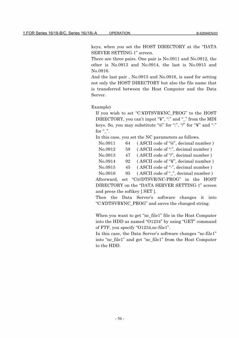
1.FOR Series 16/18-B/C, Series 16i/18i-A OPERATION B-62694EN/03
- 56 -
keys, when you set the HOST DIRECTORY at the “DATASERVER SETTING-1” screen.There are three pairs. One pair is No.0911 and No.0912, theother is No.0913 and No.0914, the last is No.0915 andNo.0916.And the last pair , No.0915 and No.0916, is used for settingnot only the HOST DIRECTORY but also the file name thatis transferred between the Host Computer and the DataServer.
Example)If you wish to set “C:¥DTSVR¥NC_PROG” to the HOSTDIRECTORY, you can’t input “¥”, “:” and “_” from the MDIkeys. So, you may substitute “@” for “:”, “/” for “¥” and “-”for “_”.In this case, you set the NC parameters as follows.
No.0911 64 ( ASCII code of “@”, decimal number )No.0912 58 ( ASCII code of “:”, decimal number )No.0913 47 ( ASCII code of “/”, decimal number )No.0914 92 ( ASCII code of “¥”, decimal number )No.0915 45 ( ASCII code of “-”, decimal number )No.0916 95 ( ASCII code of “_”, decimal number )
Afterward, set “C@/DTSVR/NC-PROG” in the HOSTDIRECTORY on the “DATA SERVER SETTING-1” screenand press the softkey [ SET ].Then the Data Server’s software changes it into“C:¥DTSVR¥NC_PROG” and saves the changed string.
When you want to get “nc_file1” file in the Host Computerinto the HDD as named “O1234” by using “GET” commandof FTP, you specify “O1234,nc-file1”.In this case, the Data Server’s software changes “nc-file1”into “nc_file1” and get “nc_file1” from the Host Computerto the HDD.

B-62694EN/03 OPERATION 1.FOR Series 16/18-B/C, Series 16i/18i-A
- 57 -
NOTE1 If the both NC parameters No.0911 and No.0912 are equal
to 0, then the NC parameters are considered to be set asfollows.No.0911 = 32 (space)No.0912 = 92 (“¥”)
2 If the both NC parameters No.0913 and No.0914 are equalto 0, then the NC parameters are considered to be set asfollows.No.0913 = 64 (“@”)No.0914 = 58 (“:”)
3 The NC parameters No.0915 and No.0916 don’t havedefault values.
4 In these three pairs, the smaller pair is availablepreferencially. That is to say, if the same value is set inNo.0911, No.0913 and No.0915, the pair of No.0911 andNo.0912 is available.
5 In case of displaying the “DATA SERVER SETTING”screen, the Data Server’s software exchanges the letters inreverse and displays the setting data.

B-62694EN/03 OPERATION 2.FOR Series 15-B
- 1 -
2 FOR Series 15-B
The operation of Data Server for Series 15-B is described inthis chapter.

2.FOR Series 15-B OPERATION B-62694EN/03
- 2 -
2.1 OUTLINE
By using this function, the following items can be achieved.(1) Drive high-speed machining operation by calling the
subprogram from a built-in hard disk on the Data Serverboard (described as “HDD” below).
(2) Input a NC program in the Host Computer into the HDDby using FTP.Output a NC program in the HDD into the Host Computerby using FTP.
(3) Input a NC program in the HDD into the memory of theCNC.Output a NC program in the memory of the CNC into theHDD.
(4) Delete NC programs and display the table of NC programsin the HDD.

B-62694EN/03 OPERATION 2.FOR Series 15-B
- 3 -
2.1.1 Notice when you use for the first time
WARNING1 If you use this function for the first time, you must initiate
the HDD according to “2.8.2 Formatting the built-in harddisk” and input the setting data according to “2.2 SETTINGSCREEN”. And turn off and then turn on the power of theCNC.If you use this function before you operate these, we don’tguarantee that this function operates normally.
2 About FTP on the Ethernet, when you use this function forthe first time, please set Ethernet addresses carefully andcheck this function on your environment according to yournetwork administrator’s advice.If you set wrong Ethernet addresses, it may make a heavyeffect on your network.
CAUTION1 If you turn off the power during reading the data from the
HDD or writing to the HDD, it may make the registered filein the HDD broken.So, you must not turn off the power during executing theData Server functions.
2 Be sure to take the backup of the data in the HDD againstan emergency.

2.FOR Series 15-B OPERATION B-62694EN/03
- 4 -
2.2 SETTING SCREEN
By using this screen, you can set the data to transfer a NC programbetween the HDD and the Host Computer with FTP.You must set the data shown as the section “2.2.1 Description of eachdata” before you use the Data Server functions.
Procedure(1) Press the function menu key in order to change the softkeys into the
function selection keys.(2) If “DATA SERVER SETTING-1” screen isn’t displayed, press the
softkey [SETTING] several times.(3) Press the operation menu key in order to change the softkeys into
the operation selection keys.(4) Input the data by using the MDI keys and the softkeys.
DATA SERVER SETTING-1 O0001 N00010(HOST-COMPUTER)
IP ADDRESS ---------------USER NAME
-------------------------------PASSWORD
-------------------------------HOST DIRECTORY
------------------------------------------------------------------------------------------------
LOCK : OFF>MDI *** STOP **** *** *** 12:34:56 ***LOCK INPUT DELETE INSERT CHAPTER +
DATA SERVER SETTING-2 O0001 N00010(DATA SERVER)
MAC ADDRESS ---------------
IP ADDRESS ---------------
MASK ADDRESS ---------------
LOCK : OFF>MDI *** STOP **** *** *** 12:34:56 ***LOCK INPUT DELETE INSERT CHAPTER +
Change two screens
by using the page
keys.

B-62694EN/03 OPERATION 2.FOR Series 15-B
- 5 -
In the above screen, means a cursor--- means a blank.
If the data are already registered, then these data aredisplayed except for the PASSWORD.About the PASSWORD, only when you set the password, itwill be displayed.

2.FOR Series 15-B OPERATION B-62694EN/03
- 6 -
2.2.1 Description of each data
(a) Setting data of the Host Computer(DATA SERVER SETTING-1)
IP ADDRESS IP address of the Host Computer’s Ethernet
board
( Ex. : ”192.168.0.1” )
USER NAME User name of the Host Computer
( Max. 31 letters )
PASSWORD Password for the above “USER NAME”
This password must be set.
( Max. 31 letters )
HOST
DIRECTORY
Working directory of the Host Computer in order
to communicate with the Data Server
( Max. 127 letters )
You can input small letters in these items.Please see the section “2.2.3 How to input small letters”.
(b) Setting data of the Data Server(DATA SERVER SETTING-2)
MAC
ADDRESS
You must input the 12 alphanumerical letters
printed as the “ADR” at the seal on the Data
Server’s face plate.
( Ex. : “080019ABCDEF” )
IP ADDRESS IP address of the Data Server board
( Ex. : ”192.168.0.2” )
MASK
ADDRESS
Netmask for the network
( Ex. : ”255.255.255.0” )
CAUTION1 If you change the above “(b) Setting data of the Data
Server” data, you must turn off the power of the CNC once.2 You must input the 12 alphanumerical letters printed as the
“ADR” at the seal on the Data Server board into the MACaddress.If you set the wrong address into the MAC address, it maymake a heavy obstacle on your network.

B-62694EN/03 OPERATION 2.FOR Series 15-B
- 7 -
The meanings of each address are as follows:MAC ADDRESS : It means the address that identifies
each machine connected by Ethernet inthe MAC layer.It must be unique in the network.
IP ADDRESS : It means the address that identifieseach machine connected by Ethernet inthe Network layer.It must be unique in the network.
MASK ADDRESS : It means a bit typed value which takesout the part of the network addressfrom the IP address.
Refer to “APPENDIX C. Ethernet technical terms” indetail.

2.FOR Series 15-B OPERATION B-62694EN/03
- 8 -
2.2.2 How to input data
In this section, how to input data is explained.
Procedure(1) Move the cursor to an item that you will input.(2) Input the data by using the MDI keys.(3) Press the softkey [INPUT] or [INSERT]. When pressing the softkey [INPUT], replace the old data
with the inputting data. When pressing the softkey [INSERT], the inputting data is
inserted at the cursor’s point.(4) If you delete a letter, move the cursor to the place where
you will delete, and then press the softkey [DELETE].
Ex.) In case of setting “192.168.0.1” into the IP ADDRESSitem(1) Move the cursor and put the cursor on the IP
ADDRESS item.
(2) Input the data “192.168.0.1” by using the MDI keys.
(3)Press the softkey [INPUT].
DATA SERVER SETTING-1 O0001 N00010(HOST-COMPUTER)
IP ADDRESS ---------------USER NAME
>MDI *** STOP **** *** *** 12:34:56 ***LOCK INPUT DELETE INSERT CHAPTER +
~ ~
DATA SERVER SETTING-1 O0001 N00010(HOST-COMPUTER)
IP ADDRESS ---------------USER NAME
>192.168.0.1MDI *** STOP **** *** *** 12:34:56 ***LOCK INPUT DELETE INSERT CHAPTER +
~ ~
DATA SERVER SETTING-1 O0001 N00010(HOST-COMPUTER)
IP ADDRESS 192.168.0.1----USER NAME
>MDI *** STOP **** *** *** 12:34:56 ***LOCK INPUT DELETE INSERT CHAPTER +
~ ~
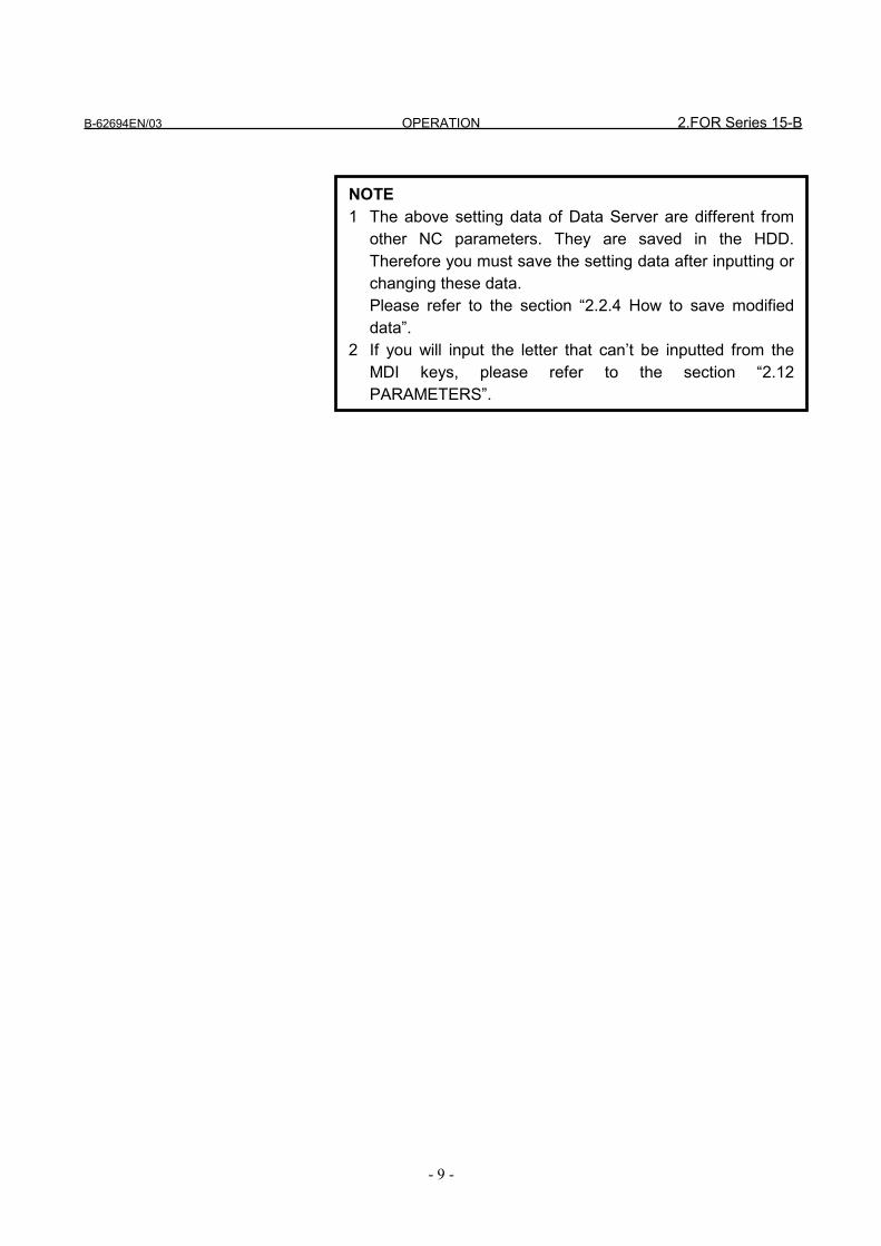
B-62694EN/03 OPERATION 2.FOR Series 15-B
- 9 -
NOTE1 The above setting data of Data Server are different from
other NC parameters. They are saved in the HDD.Therefore you must save the setting data after inputting orchanging these data.Please refer to the section “2.2.4 How to save modifieddata”.
2 If you will input the letter that can’t be inputted from theMDI keys, please refer to the section “2.12PARAMETERS”.
2.FOR Series 15-B OPERATION B-62694EN/03
- 10 -
2.2.3 How to input small letters
When you input the setting data for the Host Computer, youcan input small letters.How to input small letters is described as follows.
Procedure(1) Press the softkey [ LOCK ] before inputting small letters.
Confirm the “LOCK : ON” on the right and low of thescreen.
(2) Then the inputted letter from the MDI keys is changed to asmall letter.
(3) To cancel this mode, press the softkey [ LOCK ] again orchange the other screen.Confirm the “LOCK : OFF” on the right and low of thescreen.
B-62694EN/03 OPERATION 2.FOR Series 15-B
- 11 -
2.2.4 How to save modified data
The setting data of Data Server are different from other NCparameters. They are saved in the HDD. Therefore you mustsave the setting data by the following operation afterinputting or changing these data.If you only set the data on the screen and don’t save them,then the Ethernet communication is not effected.And if you change the CNC’s screen without saving modifieddata, then modified data are lost. So, if you display thesetting screen again, then the old data are displayed.
Procedure(1) Press the operation menu key after you finish inputting all
data.(2) Press the softkey [ SET ].(3) Press the softkey [EXEC].(4) The blinking “SET” is displayed on the low of the screen
when saving modified data.
CAUTION1 When the data are saved, the form of data is checked. If
there is a mistake in the data, the error message isdisplayed and no part of the data is saved into the HDD.In this case, “DATA SERVER APPLICATION ERROR”message is displayed on the left and low of the screen.Confirm the problem by referring to the section “2.11ERROR MESSAGE”, then set the correct data.
2 In case of changing the setting data for Host Computer(DATA SERVER SETTING-1), these saved data areavailable without turning off the power. But in case ofchanging the setting data for Data Server (DATA SERVERSETTING-2), these saved data are not available beforeturning off the power.
3 The setting screen consists of two screens, but the settingdata are saved together. Therefore, you must save thesedata after setting all data in two screens.If you save the data after setting data only in one screen,the error occurs by the reason of 1.
4 If you don’t save the data, the setting data aren’t available.
2.FOR Series 15-B OPERATION B-62694EN/03
- 12 -
2.3 NC PROGRAM MANAGEMENT FUNCTION
By using Data Server function, the following items can beachieved.
(1) Displaying the table of NC programsDisplay the table of NC programs in the HDD inalphanumerical order.
(2) Searching a NC programSearch a NC program in the HDD and display it.
(3) Deleting NC programsDelete NC programs from the HDD
(4) Getting a NC programGet a NC program from the Host Computer with GETcommand of FTP
(5) Putting a NC programPut a NC program into the Host Computer with PUTcommand of FTP
CAUTION1 Two or more items of the above can’t be operated at the
same time.2 When you are operating “Calling a subprogram with M198”
or “DNC Operation” on the buffer mode ( See “2.10BUFFER MODE” ), you can’t operate the above functions.And if you are operating neither “Calling a subprogram withM198” nor “DNC Operation” on the buffer mode, you canoperate the above functions. But in case that you create anew file into the HDD by operating “Getting a NCprogram” ,etc., the remainder of the HDD is decreased bythis new file. In this case, you may not operate on thebuffer mode because of the shortage of the HDD’sremainder. Therefore, in case of using the Data Server onthe buffer mode, you must not use “Getting a NCprogram” ,etc.
B-62694EN/03 OPERATION 2.FOR Series 15-B
- 13 -
2.3.1 Displaying the table of NC programs
You can display the table of NC programs in the HDD.
Procedure(1) Press the function menu key in order to change the
softkeys into the function selection keys.(2) If “DATA SERVER HD DIRECTORY” screen is not
displayed, press the softkey [PROGRAM] several timesuntil the following screen is displayed.
(3) Scroll the previous or next screen by pressing the page key.(4) Press the operation menu key in order to change the
softkeys into the operation selection keys.(5) Change the contents of the screen by pressing the softkey
[CHANGE].
The screens imaged for 9 inch CRT and for 14 inch CRT areshown as follows.In this manual, 9 inch CRT is used for the example screens.

2.FOR Series 15-B OPERATION B-62694EN/03
- 14 -
The screen imaged for 9 inch CRT
NOTEThe softkey [CHANGE] is displayed by pressing theoperation menu key.
DATA SERVER HD DIRECTORY O0001 N00010
REGISTERED PROGRAMS : 123FREE DISK AREA : 45678901
FILE NAME COMMENTO0001 (SHAFT XSF001 PROGRAM001 )O0002 (SHAFT XSF001 SUBPROGRAM01 )O0003 (SHAFT XSF001 SUBPROGRAM02 )O1000 (GEAR XGR001 )O2000 (GEAR XGR002 - MAIN PROGRAM)O3000 (BOLT XBT0001 - TEST PROGRA)O3200 (GEAR XGR 002 - SUBPROGRAM )O3300 (SHAFT XSF012 SAMPLE )
LOCK : OFF
MDI *** STOP **** *** *** 12:34:56 ***LOCK GETFILE PUTFILE SRHFILE CHAPTER +
DATA SERVER HD DIRECTORY O0001 N00010
REGISTERED PROGRAMS : 123FREE DISK AREA : 45678901
FILE NAME SIZE DATEO0001 12345678 94-01-11 09:10O0002 1234 93-12-30 11:11O0003 54321 94-03-21 15:39O1000 876543 94-02-21 20:47O2000 3456 94-04-01 23:59O3000 1357 93-01-15 00:03O3200 975318 94-01-01 19:32O3300 98765 94-02-14 12:00
LOCK : OFF
MDI *** STOP **** *** *** 12:34:56 ***LOCK GETFILE PUTFILE SRHFILE CHAPTER +
Change these screensby pressing the softkey[CHANGE].
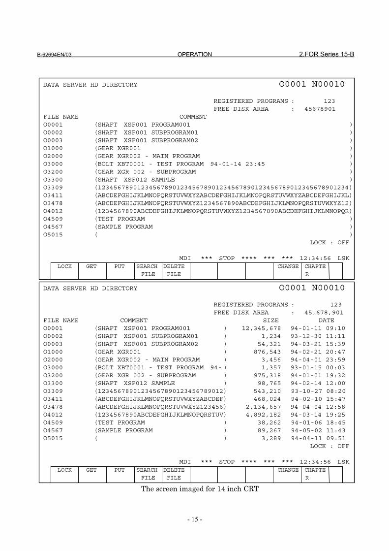
B-62694EN/03 OPERATION 2.FOR Series 15-B
- 15 -
The screen imaged for 14 inch CRT
DATA SERVER HD DIRECTORY O0001 N00010
REGISTERED PROGRAMS : 123FREE DISK AREA : 45678901
FILE NAME COMMENTO0001 (SHAFT XSF001 PROGRAM001 )O0002 (SHAFT XSF001 SUBPROGRAM01 )O0003 (SHAFT XSF001 SUBPROGRAM02 )O1000 (GEAR XGR001 )O2000 (GEAR XGR002 - MAIN PROGRAM )O3000 (BOLT XBT0001 - TEST PROGRAM 94-01-14 23:45 )O3200 (GEAR XGR 002 - SUBPROGRAM )O3300 (SHAFT XSF012 SAMPLE )O3309 (1234567890123456789012345678901234567890123456789012345678901234)O3411 (ABCDEFGHIJKLMNOPQRSTUVWXYZABCDEFGHIJKLMNOPQRSTUVWXYZABCDEFGHIJKL)O3478 (ABCDEFGHIJKLMNOPQRSTUVWXYZ1234567890ABCDEFGHIJKLMNOPQRSTUVWXYZ12)O4012 (1234567890ABCDEFGHIJKLMNOPQRSTUVWXYZ1234567890ABCDEFGHIJKLMNOPQR)O4509 (TEST PROGRAM )O4567 (SAMPLE PROGRAM )O5015 ( )
LOCK : OFF
MDI *** STOP **** *** *** 12:34:56 LSKLOCK GET PUT SEARCH DELETE CHANGE CHAPTE
FILE FILE R
DATA SERVER HD DIRECTORY O0001 N00010
REGISTERED PROGRAMS : 123FREE DISK AREA : 45,678,901
FILE NAME COMMENT SIZE DATEO0001 (SHAFT XSF001 PROGRAM001 ) 12,345,678 94-01-11 09:10O0002 (SHAFT XSF001 SUBPROGRAM01 ) 1,234 93-12-30 11:11O0003 (SHAFT XSF001 SUBPROGRAM02 ) 54,321 94-03-21 15:39O1000 (GEAR XGR001 ) 876,543 94-02-21 20:47O2000 (GEAR XGR002 - MAIN PROGRAM ) 3,456 94-04-01 23:59O3000 (BOLT XBT0001 - TEST PROGRAM 94- ) 1,357 93-01-15 00:03O3200 (GEAR XGR 002 - SUBPROGRAM ) 975,318 94-01-01 19:32O3300 (SHAFT XSF012 SAMPLE ) 98,765 94-02-14 12:00O3309 (12345678901234567890123456789012) 543,210 93-10-27 08:20O3411 (ABCDEFGHIJKLMNOPQRSTUVWXYZABCDEF) 468,024 94-02-10 15:47O3478 (ABCDEFGHIJKLMNOPQRSTUVWXYZ123456) 2,134,657 94-04-04 12:58O4012 (1234567890ABCDEFGHIJKLMNOPQRSTUV) 4,892,182 94-03-14 19:25O4509 (TEST PROGRAM ) 38,262 94-01-06 18:45O4567 (SAMPLE PROGRAM ) 89,267 94-05-02 11:43O5015 ( ) 3,289 94-04-11 09:51
LOCK : OFF
MDI *** STOP **** *** *** 12:34:56 LSKLOCK GET PUT SEARCH DELETE CHANGE CHAPTE
FILE FILE R

2.FOR Series 15-B OPERATION B-62694EN/03
- 16 -
Change the above screens by pressing the softkey[CHANGE].
Each item means as follows,REGISTERED PROGRAMS
: number of registered NC programs inthe HDD
FREE DISK AREA
: free disk space in the HDD (unit : byte)
FILE NAME : NC program nameCOMMENT : comment in a NC programSIZE : size of a NC program (unit : byte)DATE : registered date of a NC program
B-62694EN/03 OPERATION 2.FOR Series 15-B
- 17 -
2.3.2 Searching a NC program
When the table of NC programs in the HDD is displayed, youcan display the specified file at the top of the screen.
Procedure(1) Press the softkey [SRHFILE].(2) Press the softkey [(PROG#)] and input an O-number of the
NC program that you will search.(3) Press the softkey [EXEC].(4) Display the table of NC programs so that the top is the
specified NC program.(5) The blinking “SRCH” is displayed on the low of the screen
when searching.
CAUTIONIf the specified NC program doesn’t exist in the HDD, thenext NC program in alphanumerical order is displayed atthe top of the screen.

2.FOR Series 15-B OPERATION B-62694EN/03
- 18 -
2.3.3 Deleting NC programs
You can delete NC programs from the HDD.
Procedure(1) Display the “DATA SERVER HD DIRECTORY” screen. (2) The softkey [DELFILE] is displayed by pressing the
operation menu key.(3) Press the softkey [DELFILE].(4) Press the softkey [(PROG#)]. (5) Input an O-number of the NC program that you will delete.(6) Press the softkey [ EXEC ].(7) The message “FILE DELETE ?” is displayed on the left and
low of the screen, so if you want to delete, press the softkey[EXEC] again.
(8) The blinking “DELE” is displayed on the low of the screenwhen deleting.
[Reference]In case of deleting NC programs, you can use the wild card“*” in an O-number.Example :
DATA SERVER HD DIRECTORY O0001 N00010
REGISTERED PROGRAMS : 123FREE DISK AREA : 45678901
FILE NAME COMMENTO0001 (SHAFT XSF001 PROGRAM001 )
O3200 (GEAR XGR 002 - SUBPROGRAM )O3300 (SHAFT XSF012 SAMPLE )
LOCK : OFF
MDI *** STOP **** *** *** 12:34:56 ***LOCK GETFILE PUTFILE SRHFILE CHAPTER +
~ ~
DATA SERVER HD DIRECTORY O0001 N00010
REGISTERED PROGRAMS : 123FREE DISK AREA : 45678901
FILE NAME COMMENTO0001 (SHAFT XSF001 PROGRAM001 )
O3200 (GEAR XGR 002 - SUBPROGRAM )O3300 (SHAFT XSF012 SAMPLE )
LOCK : OFFDELFILE > OMDI *** STOP **** *** *** 12:34:56 ***LOCK CANCEL EXEC
~ ~

B-62694EN/03 OPERATION 2.FOR Series 15-B
- 19 -
(1) In case of deleting all NC programs in the HDD, youwill specify “O*” as an O-number.
(2) In case of deleting NC programs from O0100 toO0199, you will specify “O01*” as an O-number.
In case that you specify “O12*0”, ignore letters latter thanthe “*”, so that “O12*0” is equal to “O12*”. In both cases,delete NC programs from O1200 to O1299.
In case of deleting NC programs by using the wild card,you can stop deleting NC programs by pressing the softkey[ STOP ]. However, you can’t recover the files that aredeleted before stopping.And the softkey [STOP] is displayed when this functionexecutes.

2.FOR Series 15-B OPERATION B-62694EN/03
- 20 -
2.3.4 Getting a NC program
You can get a NC program from the Host Computer with“GET” command of FTP, and register it into the HDD.
Procedure(1) Display the “DATA SERVER HD DIRECTORY” screen. (2) Press the softkey [GETFILE].(3) Press the softkey [(PROG#)] and input an O-number of the
NC program that you will register into the HDD.(4) If the file that you will get is registered in the Host
Computer as the same name with the specified O-numberat (3), press the softkey [EXEC].If not, operate the following operations (5) and (6).
(5) Press the softkey [(F NAM)] and input a file name that youwill get into the HDD.
(6) Press the softkey [EXEC].(7) The blinking “GET” is displayed on the low of the screen
when getting a NC program.
DATA SERVER HD DIRECTORY O0001 N00010
REGISTERED PROGRAMS : 123FREE DISK AREA : 45678901
FILE NAME COMMENTO0001 (SHAFT XSF001 PROGRAM001 )
O3200 (GEAR XGR 002 - SUBPROGRAM )O3300 (SHAFT XSF012 SAMPLE )
LOCK : OFF
MDI *** STOP **** *** *** 12:34:56 ***LOCK GETFILE PUTFILE SRHFILE CHAPTER +
~ ~
NOTE1 You must specify an O-number that is not registered in the
HDD at the procedure (3).If you specify the registered O-number, an error occurs.
2 You can use small letters for a file name of the HostComputer at the procedure (5).Input a letter from A to Z after pressing the softkey[ LOCK ]. This softkey [ LOCK ] is available till pressing thissoftkey [ LOCK ] again.
3 In case that the file name stored in the Host Computerincludes a letter that can’t be inputted from the MDI keys,you can specify the substitutional letter for only one letter.Refer to the section “2.12 PARAMETERS”.

B-62694EN/03 OPERATION 2.FOR Series 15-B
- 21 -
[Example](1) In case that you register “TEST.PRG” in the Host
Computer as the name of “O0001” into the HDD, firstpress the softkeys [GETFILE] and [(PROG#)] and input“0001”.Then press the softkey [(F NAM)] and input a file name“TEST.PRG”. At last, press the softkey [EXEC].
(2) In case that you register “O0002” in the Host Computeras the name of “O0002” into the HDD, press thesoftkeys [GETFILE] and [(PROG#)] and input “0002”.Then press the softkey [EXEC].
NOTE1 In case of transferring a large NC program, you are careful
because you can’t stop “GET” function.2 If an error occurs in this function, “DATA SERVER
APPLICATION ERROR” is displayed on the left and low ofthe screen.Confirm the problem by referring to the section “2.11ERROR MESSAGE”. About error messages, refer to thesection “APPENDIX A. TABLE OF ERROR MESSAGES”.
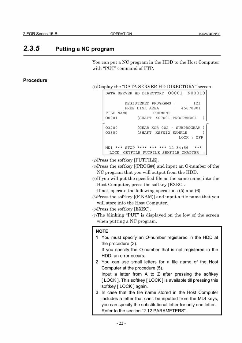
2.FOR Series 15-B OPERATION B-62694EN/03
- 22 -
2.3.5 Putting a NC program
You can put a NC program in the HDD to the Host Computerwith “PUT” command of FTP.
Procedure(1) Display the “DATA SERVER HD DIRECTORY” screen. (2) Press the softkey [PUTFILE].(3) Press the softkey [(PROG#)] and input an O-number of the
NC program that you will output from the HDD.(4) If you will put the specified file as the same name into the
Host Computer, press the softkey [EXEC].If not, operate the following operations (5) and (6).
(5) Press the softkey [(F NAM)] and input a file name that youwill store into the Host Computer.
(6) Press the softkey [EXEC].(7) The blinking “PUT” is displayed on the low of the screen
when putting a NC program.
DATA SERVER HD DIRECTORY O0001 N00010
REGISTERED PROGRAMS : 123FREE DISK AREA : 45678901
FILE NAME COMMENTO0001 (SHAFT XSF001 PROGRAM001 )
O3200 (GEAR XGR 002 - SUBPROGRAM )O3300 (SHAFT XSF012 SAMPLE )
LOCK : OFF
MDI *** STOP **** *** *** 12:34:56 ***LOCK GETFILE PUTFILE SRHFILE CHAPTER +
~ ~
NOTE1 You must specify an O-number registered in the HDD at
the procedure (3).If you specify the O-number that is not registered in theHDD, an error occurs.
2 You can use small letters for a file name of the HostComputer at the procedure (5).Input a letter from A to Z after pressing the softkey[ LOCK ]. This softkey [ LOCK ] is available till pressing thissoftkey [ LOCK ] again.
3 In case that the file name stored in the Host Computerincludes a letter that can’t be inputted from the MDI keys,you can specify the substitutional letter for only one letter.Refer to the section “2.12 PARAMETERS”.

B-62694EN/03 OPERATION 2.FOR Series 15-B
- 23 -
[Example](1) In case that you register “O0001” in the HDD as the
name of “TEST.PRG” into the Host Computer, firstpress the softkeys [PUTFILE] and [(PROG#)] and input“0001”.Then press the softkey [(F NAM)] and input a file name“TEST.PRG”. At last, press the softkey [EXEC].
(2) In case that you register “O0002” in the HDD as thename of “O0002” into the Host Computer, press thesoftkeys [PUTFILE] and [(PROG#)] and input “0002”.Then press the softkey [EXEC].
(3) In case that you register “COMMON.RAM” in the HDDas the name of “COMMON.RAM” into the HostComputer, input “COMMON.RAM,COMMON.RAM” oronly “COMMON.RAM” and press the softkey[PUTFILE].
NOTE4 If you transfer a file except for O-number, before pressing
the softkey [PUTFILE], input a file name that you will putinto the Host Computer. Then press the softkey[PUTFILE].This method is used for the transmission of the“COMMON.RAM” file, etc.About “COMMON.RAM” file, refer to the section “2.9MAINTENANCE OF DATA SERVER”.
NOTE1 In case of transferring a large NC program, you are careful
because you can’t stop “PUT” function.2 If an error occurs in this function, “DATA SERVER
APPLICATION ERROR” is displayed on the left and low ofthe screen.Confirm the problem by referring to the section “2.11ERROR MESSAGE”. About error messages, refer to thesection “APPENDIX A. TABLE OF ERROR MESSAGES”.
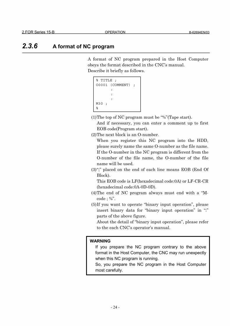
2.FOR Series 15-B OPERATION B-62694EN/03
- 24 -
2.3.6 A format of NC program
A format of NC program prepared in the Host Computerobeys the format described in the CNC’s manual.Describe it briefly as follows.
(1) The top of NC program must be “%”(Tape start).And if necessary, you can enter a comment up to firstEOB code(Program start).
(2) The next block is an O-number.When you register this NC program into the HDD,please surely name the same O-number as the file name.If the O-number in the NC program is different from theO-number of the file name, the O-number of the filename will be used.
(3) “;” placed on the end of each line means EOB (End OfBlock).This EOB code is LF(hexadecimal code:0A) or LF-CR-CR(hexadecimal code:0A-0D-0D).
(4) The end of NC program always must end with a “M-code ; %”.
(5) If you want to operate “binary input operation”, pleaseinsert binary data for “binary input operation” in “:”parts of the above figure.About the detail of “binary input operation”, please referto the each CNC’s operator’s manual.
% TITLE ;O0001 (COMMENT) ;
:::
M30 ;%
WARNINGIf you prepare the NC program contrary to the aboveformat in the Host Computer, the CNC may run unexpectlywhen this NC program is running.So, you prepare the NC program in the Host Computermost carefully.

B-62694EN/03 OPERATION 2.FOR Series 15-B
- 25 -
2.4 CALLING A SUBPROGRAM WITH M198
When the subprogram is called by M198 code in mainprogram stored in the memory of CNC, the CNC reads thesubprogram from the HDD.
Format of M198 code in the main program M198P****L@@@@;
**** : the integer of four digits that expresses the O-number
@@@@ : repeat time (from 1 to 9999). When it is omitted, it is supposed to be 1.
The other item related to M198 code is based on “subprogramcall function” in external input/output devices.Refer to the CNC’s manual in detail.
[Example]Main program Sub program
(the memory of CNC) (HDD of Data Server)
%;O1234(SUB PROGRAM);
::::::::
M99;%
%;O0001(MAIN PROGRAM);
:::
M198P1234;::::
M30;%
NOTE1 You must set “14” on the NC parameter of I/O Channel
(No.0022) in order to use this function.2 You must set the NC parameter No.7616 #3(EXSC) to 1 in
order to operate this function.3 You can not call the subprogram in the HDD again in the
called subprogram on this function, but you can call thesubprogram in the memory of CNC.

2.FOR Series 15-B OPERATION B-62694EN/03
- 26 -
NOTE4 The Data Server is equal to other external input/output
devices from view point of a CNC.So, the limitation related to “subprogram call function” forthe Data Server is equal to the one for other externalinput/output devices.
5 You can not execute this function together with “2.5REGISTERING A NC PROGRAM”, “2.6 OUTPUTTING ANC PROGRAM” or “2.7 DNC OPERATION”.
6 You can call a subprogram by M-code that is set to the NCparameter No.2431.Please refer to the CNC’s manual in detail.

B-62694EN/03 OPERATION 2.FOR Series 15-B
- 27 -
2.5 REGISTERING A NC PROGRAM
You can register a NC program in the HDD to the memory ofCNC.
Procedure(1) Change the mode of the CNC into “EDIT” mode (in case of
foreground operation).(2) Press the function menu key in order to change the
softkeys into the function selection keys.(3) If “PROGRAM(MEMORY)” screen is not displayed, press
the softkey [PROGRAM] several times until this screen isdisplayed.
(4) Press the operation menu key in order to change thesoftkeys into the operation selection keys.
(5) Press the softkey [READ].(6) Press the softkey [(PROG#)] and input an O-number of the
NC program that you will register from the HDD to thememory of CNC.
(7) Press the softkey [ EXEC ].(8) The blinking “READ” is displayed on the right and low of
the screen when registering a NC program.
CAUTION1 When you register a NC program to the memory of CNC,
please take care of the O-number of the registered NCprogram in the CNC. In case that the NC parameterNo.2200 #1(REP) is equal to 1, if your specified O-numberexists in the CNC, the old NC program is overwritten.And if the NC parameter No.2200 #0(RDL) is equal to 1,register the specified NC program after deleting all NCprograms in the memory of CNC.
2 If you use the buffer mode ( See “2.10 BUFFER MODE” ),this function runs as it is the buffer mode. Therefore, theData Server software understands the specified O-numberas the list of files and gets divided NC programs from theHost Computer. So, you must not use this function on thebuffer mode.

2.FOR Series 15-B OPERATION B-62694EN/03
- 28 -
NOTE1 You must set “14” on the NC parameter of I/O Channel
(No.0020) in order to use this function.2 You can not execute this function together with “2.4
CALLING A SUBPROGRAM WITH M198”, “2.6OUTPUTTING A NC PROGRAM” or “2.7 DNCOPERATION”.
3 You can execute this function under background operation.In this case, you must set the NC parameter No.0022 to14. Please refer to the CNC’s manual in detail.

B-62694EN/03 OPERATION 2.FOR Series 15-B
- 29 -
2.6 OUTPUTTING A NC PROGRAM
You can output a NC program in the memory of CNC to theHDD.
Procedure(1) Change the mode of the CNC into “EDIT” mode (in case of
foreground operation).(2) Press the function menu key in order to change the
softkeys into the function selection keys.(3) If “PROGRAM(MEMORY)” screen is not displayed, press
the softkey [PROGRAM] several times until this screen isdisplayed.
(4) Press the operation menu key in order to change thesoftkeys into the operation selection keys.
(5) Press the softkey [PUNCH].(6) Press the softkey [(PROG#)] and input an O-number of the
NC program that you will output from the memory of CNCto the HDD.
(7) Press the softkey [ EXEC ].(8) The blinking “PNCH” is displayed on the right and low of
the screen when outputting a NC program.
NOTE1 You must set “14” on the NC parameter of I/O Channel
(No.0021) in order to use this function.2 You can not execute this function together with “2.4
CALLING A SUBPROGRAM WITH M198”, “2.5REGISTERING A NC PROGRAM” or “2.7 DNCOPERATION”.
3 You can execute this function under background operation.In this case, you must set the NC parameter No.0023 to14. Please refer to the CNC’s manual in detail.
4 If you specify the NC program that already exists in theHDD, an error occurs.Please change O-number in the memory of CNC or deletea NC program from the HDD.

2.FOR Series 15-B OPERATION B-62694EN/03
- 30 -
2.7 DNC OPERATION
You can drive the DNC operation by using the NC programin the HDD.
Procedure(1) Change the mode of CNC into “TAPE” mode.(1) Display the screen of “2.3.1 Display the table of NC
programs”.And input an O-number of the NC program that you will
use with the DNC operation and press thefunction key.
(2) So, the item “DNC FILE NAME” and the specified O-number are displayed on the right and high of the screen.
(3) Start driving the DNC operation with the cycle startswitch.
INPUTINPUTINPUTINPUT
NOTE1 You must set “14” on the NC parameter of I/O Channel
(No.0022) in order to use this function.2 You can not execute this function together with “2.4
CALLING A SUBPROGRAM WITH M198”, “2.5REGISTERING A NC PROGRAM” or “2.6 OUTPUTTINGA NC PROGRAM”.
DATA SERVER HD DIRECTORY O0001 N00010DNC FILE NAME : O0001REGISTERED PROGRAMS : 123FREE DISK AREA : 45678901
FILE NAME COMMENTO0001 (SHAFT XSF001 PROGRAM001 )
O3200 (GEAR XGR 002 - SUBPROGRAM )O3300 (SHAFT XSF012 SAMPLE )
LOCK : OFF
TAPE*** STOP **** *** *** 12:34:56 ***LOCK GETFILE PUTFILE SRHFILE CHAPTER +
~ ~

B-62694EN/03 OPERATION 2.FOR Series 15-B
- 31 -
2.8 MAINTENANCE OF THE BUILT-IN HARD DISK
You can maintain or set the HDD by using this screen.
Procedure(1) Press the function menu key in order to change the
softkeys into the function selection keys.(2) If “MAINTENANCE OF DATA SERVER” screen is not
displayed, press the softkey [SERVICE] several times untilthis screen is displayed.
(3) Press the operation menu key in order to change thesoftkeys into the operation selection keys.
(4) You can execute maintenance services by pressing thesoftkey.
[Reference]Each item means as follows.These items are used when transferring a NCprogram from Data Server to the CNC. Therefore,other services are not related to these.(A) TOTAL SIZE
This item shows the total byte size of one NCprogram, when transfer a NC program from theData Server to the CNC.
(B) READ POINTER(C) WRITE POINTER
These items show the inside pointer formanagement of the data buffer.
MAINTENANCE OF DATA SERVER O0001 N00010
STORAGE MODE
TOTAL SIZE 9999999999
READ POINTER 99999
WRITE POINTER 99999
>MDI *** STOP **** *** *** 12:34:56 ***SAVE FORMAT CHKDSK MODE CHAPTER
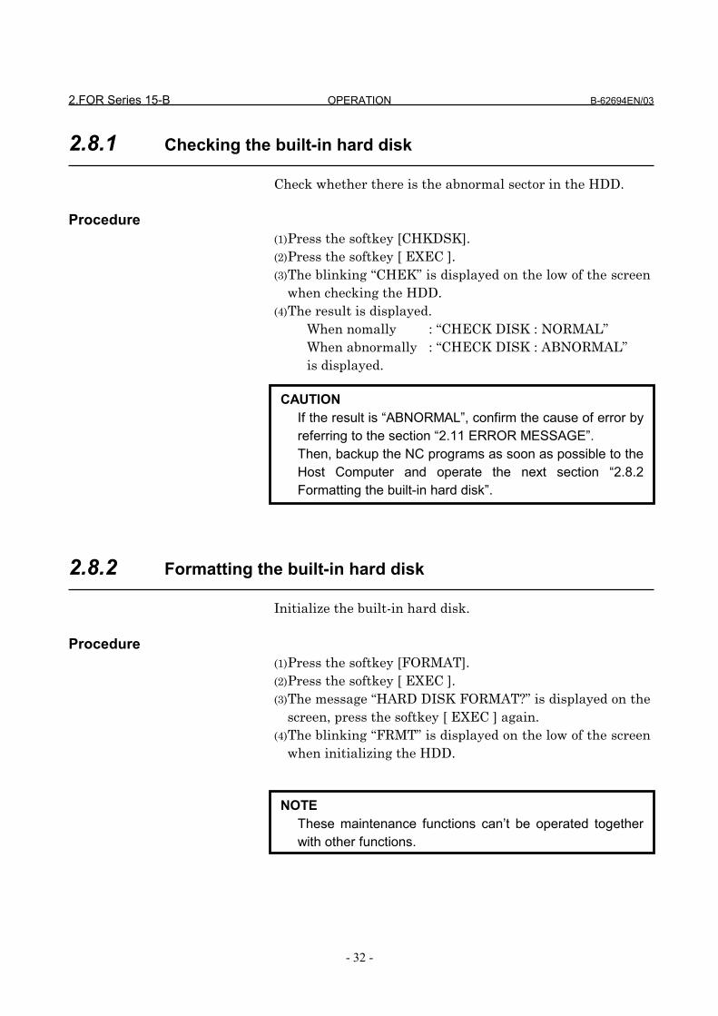
2.FOR Series 15-B OPERATION B-62694EN/03
- 32 -
2.8.1 Checking the built-in hard disk
Check whether there is the abnormal sector in the HDD.
Procedure(1) Press the softkey [CHKDSK].(2) Press the softkey [ EXEC ].(3) The blinking “CHEK” is displayed on the low of the screen
when checking the HDD.(4) The result is displayed.
When nomally : “CHECK DISK : NORMAL”When abnormally : “CHECK DISK : ABNORMAL”is displayed.
2.8.2 Formatting the built-in hard disk
Initialize the built-in hard disk.
Procedure(1) Press the softkey [FORMAT].(2) Press the softkey [ EXEC ].(3) The message “HARD DISK FORMAT?” is displayed on the
screen, press the softkey [ EXEC ] again.(4) The blinking “FRMT” is displayed on the low of the screen
when initializing the HDD.
CAUTIONIf the result is “ABNORMAL”, confirm the cause of error byreferring to the section “2.11 ERROR MESSAGE”.Then, backup the NC programs as soon as possible to theHost Computer and operate the next section “2.8.2Formatting the built-in hard disk”.
NOTEThese maintenance functions can’t be operated togetherwith other functions.

B-62694EN/03 OPERATION 2.FOR Series 15-B
- 33 -
2.9 MAINTENANCE OF DATA SERVER
If the trouble occurs at the Data Server function, thecontents of COMMON RAM for the interface between CNCand Data Server can be saved into a file in order to examineit.This file is transferred to the Host Computer by using “2.3.5Putting a NC program” and the inside status of the DataServer is checked by this file.
Procedure(1) Press the function menu key in order to change the
softkeys into the function selection keys.(2) If “MAINTENANCE OF DATA SERVER” screen is not
displayed, press the softkey [SERVICE] several times untilthis screen is displayed.
(3) Press the operation menu key in order to change thesoftkeys into the operation selection keys.
(4) Press the softkey [ SAVE ].(5) Press the softkey [ EXEC ], so that the contents of
COMMON RAM are saved into the file as“COMMON.RAM”.
(6) The blinking “SAVE” is displayed on the low of the screenwhen saving.
About meaning of each item, refer to the section “2.8MAINTENANCE OF THE BUILT-IN HARD DISK”.
MAINTENANCE OF DATA SERVER O0001 N00010
STORAGE MODE
TOTAL SIZE 9999999999
READ POINTER 99999
WRITE POINTER 99999
>MDI *** STOP **** *** *** 12:34:56 ***SAVE FORMAT CHKDSK MODE CHAPTER

2.FOR Series 15-B OPERATION B-62694EN/03
- 34 -
NOTEThe contents of this file are binary codes.So, after transferring this file to the Host Computer byusing “2.3.5 Putting a NC program” function, whentransferring this file from the Host Computer to the othercomputer again, please transfer it on the binary mode.If you transfer it on the text mode, the contents of this filemay be broken.
B-62694EN/03 OPERATION 2.FOR Series 15-B
- 35 -
2.10 BUFFER MODE (OPTIONAL FUNCTION)
The software of the Data Server can operate on theSTORAGE mode or the BUFFER mode. The software on thestorage mode can do the services mentioned in the previoussections, but can’t control a larger NC program than the sizeof the built-in hard disk.The buffer mode is used to control a larger NC program thanthe size of the built-in hard disk. On this buffer mode, thebuilt-in hard disk is divided into two areas(area A, areaB)virtually. A part of a NC program in one area of the built-inhard disk is supplied to the CNC and a continuous part of theNC program is got into another area in the built-in hard diskby using FTP at the same time. A larger NC program thanthe size of the built-in hard disk can be controlled byrepeating the above operation.But you must divide a larger NC program than the size of thebuilt-in hard disk into some files with about 35MB in theHost Computer in advance. Now, there are some kinds ofbuilt-in hard disk, but we recommend that the divided size isabout 35MB. Because you can divide the NC program intothe size larger than 35MB, but if so, more time is necessaryto get the first file from the Host Computer.
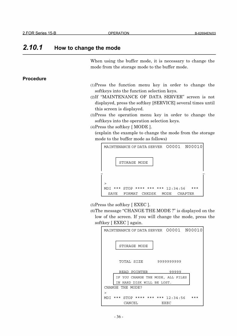
2.FOR Series 15-B OPERATION B-62694EN/03
- 36 -
2.10.1 How to change the mode
When using the buffer mode, it is necessary to change themode from the storage mode to the buffer mode.
Procedure(1) Press the function menu key in order to change the
softkeys into the function selection keys.(2) If “MAINTENANCE OF DATA SERVER” screen is not
displayed, press the softkey [SERVICE] several times untilthis screen is displayed.
(3) Press the operation menu key in order to change thesoftkeys into the operation selection keys.
(4) Press the softkey [ MODE ].(explain the example to change the mode from the storagemode to the buffer mode as follows)
(5) Press the softkey [ EXEC ].(6) The message “CHANGE THE MODE ?” is displayed on the
low of the screen. If you will change the mode, press thesoftkey [ EXEC ] again.
MAINTENANCE OF DATA SERVER O0001 N00010
STORAGE MODE
TOTAL SIZE 9999999999
READ POINTER 99999
CHANGE THE MODE?>MDI *** STOP **** *** *** 12:34:56 ***
CANCEL EXEC
IF YOU CHANGE THE MODE, ALL FILES
IN HARD DISK WILL BE LOST.
MAINTENANCE OF DATA SERVER O0001 N00010
STORAGE MODE
>MDI *** STOP **** *** *** 12:34:56 ***SAVE FORMAT CHKDSK MODE CHAPTER
~ ~

B-62694EN/03 OPERATION 2.FOR Series 15-B
- 37 -
(7) The blinking “MODE” is displayed on the low of the screenwhen changing the mode.
(8) The mode on the left and high of the screen is changedafter changing the mode.
CAUTION1 If you change the mode, all NC programs in the HDD will
be lost.2 Even if you turn off the power, the mode is kept. Therefore,
if you turn off the CNC on the buffer mode and then turn onthe CNC, the Data Server runs on the buffer mode.
NOTE1 When using this function, the software option is necessary.
In case that this software option is not set, the abovesoftkey [ MODE ] is not displayed.
2 On the buffer mode, if you are operating neither “Calling asubprogram with M198” nor “DNC operation”, you canoperate “Outputting a NC program”.But in case that you create a new file into the HDD by using“Outputting a NC program”, when you operate “Calling asubprogram with M198”, you must care about the size ofthe divided files. Because the remainder of the HDD isdecreased by the new files.If you can’t operate on the buffer mode because of theshortage of the HDD’s remainder, please delete the newfiles with “2.3.3 Deleting NC programs”.
MAINTENANCE OF DATA SERVER O0001 N00010
BUFFER MODE
>MDI *** STOP **** *** *** 12:34:56 ***SAVE FORMAT CHKDSK MODE CHAPTER
~ ~
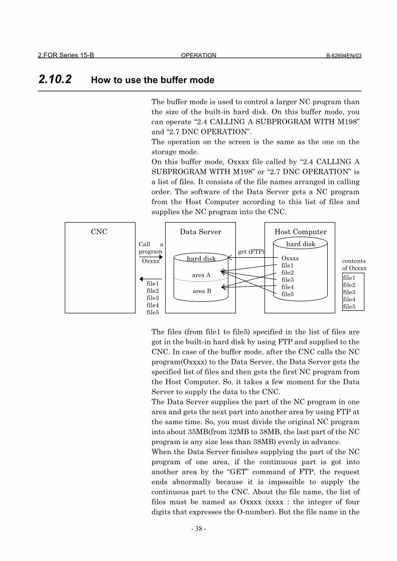
2.FOR Series 15-B OPERATION B-62694EN/03
- 38 -
2.10.2 How to use the buffer mode
The buffer mode is used to control a larger NC program thanthe size of the built-in hard disk. On this buffer mode, youcan operate “2.4 CALLING A SUBPROGRAM WITH M198”and “2.7 DNC OPERATION”.The operation on the screen is the same as the one on thestorage mode.On this buffer mode, Oxxxx file called by “2.4 CALLING ASUBPROGRAM WITH M198” or “2.7 DNC OPERATION” isa list of files. It consists of the file names arranged in callingorder. The software of the Data Server gets a NC programfrom the Host Computer according to this list of files andsupplies the NC program into the CNC.
CNC Data Server Host Computer
The files (from file1 to file5) specified in the list of files aregot in the built-in hard disk by using FTP and supplied to theCNC. In case of the buffer mode, after the CNC calls the NCprogram(Oxxxx) to the Data Server, the Data Server gets thespecified list of files and then gets the first NC program fromthe Host Computer. So, it takes a few moment for the DataServer to supply the data to the CNC.The Data Server supplies the part of the NC program in onearea and gets the next part into another area by using FTP atthe same time. So, you must divide the original NC programinto about 35MB(from 32MB to 38MB, the last part of the NCprogram is any size less than 38MB) evenly in advance.When the Data Server finishes supplying the part of the NCprogram of one area, if the continuous part is got intoanother area by the “GET” command of FTP, the requestends abnormally because it is impossible to supply thecontinuous part to the CNC. About the file name, the list offiles must be named as Oxxxx (xxxx : the integer of fourdigits that expresses the O-number). But the file name in the
contentsof Oxxxx
file1file2file3file4file5
hard diskget (FTP)
Call aprogram
Oxxxx Oxxxxfile1file2file3file4file5
file1file2file3file4file5
hard disk
area A
area B

B-62694EN/03 OPERATION 2.FOR Series 15-B
- 39 -
list of files is anything ( the length of the file name must beless than 255 letters, and the file name must be available forthe Host Computer). The Data Server operates only in thedirectory specified at “HOST DIRECTORY” of “2.2 SETTINGSCREEN”.LF (hexadecimal : 0A) or CR (hexadecimal : 0D) must beadded to the end of each file name in the list of files.
NOTEIf you use the Data Server with 256MB HDD or 810MBHDD, you can divide the original NC program into about120MB or 400MB theoretically. But if the divided size islarge, the time for reading the NC program from the HostComputer and transmitting the NC program to the CNCbecomes larger. Therefore, we recommend that you dividethe original NC program into about 35MB.

2.FOR Series 15-B OPERATION B-62694EN/03
- 40 -
2.10.3 How to divide a large NC program
If you will operate the Data Server on the buffer mode, youmust divide a large NC program into some files with about35MB in the Host Computer and create a file that consists ofthe file name of the divided files in advance as follows.
Example)In case that a large NC program is divided into three partswithout separating one block
An original NC program is divided into three parts like theabove. And all the divided files are specified in the file asO1234 in order.
NOTEIn case of the above example, a NC program is dividedwithout separating one block. But it is possible that a NCprogram is divided with separating one block, provided thatyou don’t add the unnecessary letter after the bottom ofeach file.
%
O1234(SAMPLE);・・・
X1.Y1.Z1.;
%
O1234(SAMPLE);・・・
X1.Y1.Z1.;
X2.Y2.Z2.;・・・
X3.Y3.Z3.;
X4.Y4.Z4.;・・・
M30;
%
X2.Y2.Z2.;・・・
X3.Y3.Z3.;
X4.Y4.Z4.;・・・
M30;
%
file1
file2
file3
file1
an original NC program
divide intothree parts
the list of files
file2
file3
O1234

B-62694EN/03 OPERATION 2.FOR Series 15-B
- 41 -
Example)In case that a large NC program is divided into three partswith separating one block
WARNINGIn case of the above division, you must not add theunnecessary letter as “CR”, “LF”, “EOF”(End Of File) andso on, after the bottom of each file.If the unnecessary letter is added, the CNC may rununexpectly when this NC program is running.
%
O1234(SAMPLE);
•••
X1.Y
%
O1234(SAMPLE);
•••
X1.Y1.Z1.;
X2.Y2.Z2.;
•••
X3.Y3.Z3.;
X4.Y4.Z4.;
•••
M30;
%
1.Z1.;
X2.Y2.Z2.;
••
X3.Y3
.Z3.;
X4.Y4.Z4.;
••
M30;
%
file1
file2
file3
file1
an original NC program
divide intothree parts
the list of files
file2
file3
O1234

2.FOR Series 15-B OPERATION B-62694EN/03
- 42 -
2.11 ERROR MESSAGE
If an error occurs in the Data Server function, the errordescription is displayed on the following error messagescreen for the Data Server function. So, if an error occurs, seethis screen and confirm the description.
Procedure(1) Press the function menu key in order to change the
softkeys into the function selection keys.(2) If “DATA SERVER MESSAGE-1” screen is not displayed,
press the softkey [MESSAGE] several times until thisscreen is displayed.The last error message is shown at the top of screen.
DATA SERVER MESSAGE-1 O0001 N00010
--------------------------- 940710 1134------------------ 940510 1649---------------------- 940327 0956
----------------------- 940312 1202
>MDI *** STOP **** *** *** 12:34:56 ***
CHAPTER
DATA SERVER MESSAGE-2 O0001 N00010
DATA-SERVER SYSTEM ROM nnnn [x] yy/mm/ddCPU : GENERAL PROTECTION
0000 0000 0000 0000 0000 0000 0000 000000000000 00000000 00000000 0000000000000000 00000000 00000000 0000000000000000 00000000
0000 0000:000000000000 0000:00000000 0000 0000 0000 0000 0000 0000 00000000 0000 0000 0000 0000 0000 0000 0000
>MDI *** STOP **** *** *** 12:34:56 ***
CHAPTER
Change these screensby pressing the pagekeys.

B-62694EN/03 OPERATION 2.FOR Series 15-B
- 43 -
The detail error information is displayed on the “DATASERVER MESSAGE-1” screen. And the time stamp isdisplayed on the right side of the error message.The time stamp is shown as the format “yymmddhhMM”(year is ”yy”, month is ”mm”, day is ”dd”, hour is“hh” and minute is “MM”).When the serious error occurs on the software of the DataServer, the inside status (Ex. value of the registers) of theData Server’s software is shown on the “DATA SERVERMESSAGE-2” screen. Usually, no data are shown on thisscreen.
NOTE1 Refer to “APPENDIX A. TABLE OF ERROR MESSAGES”
and “APPENDIX B. SERIOUS ERROR” in detail.2 If the information is shown on the “DATA SERVER
MESSAGE-2” screen, the Data Server’s software can’t runcontinuously. It is necessary to turn off the power.
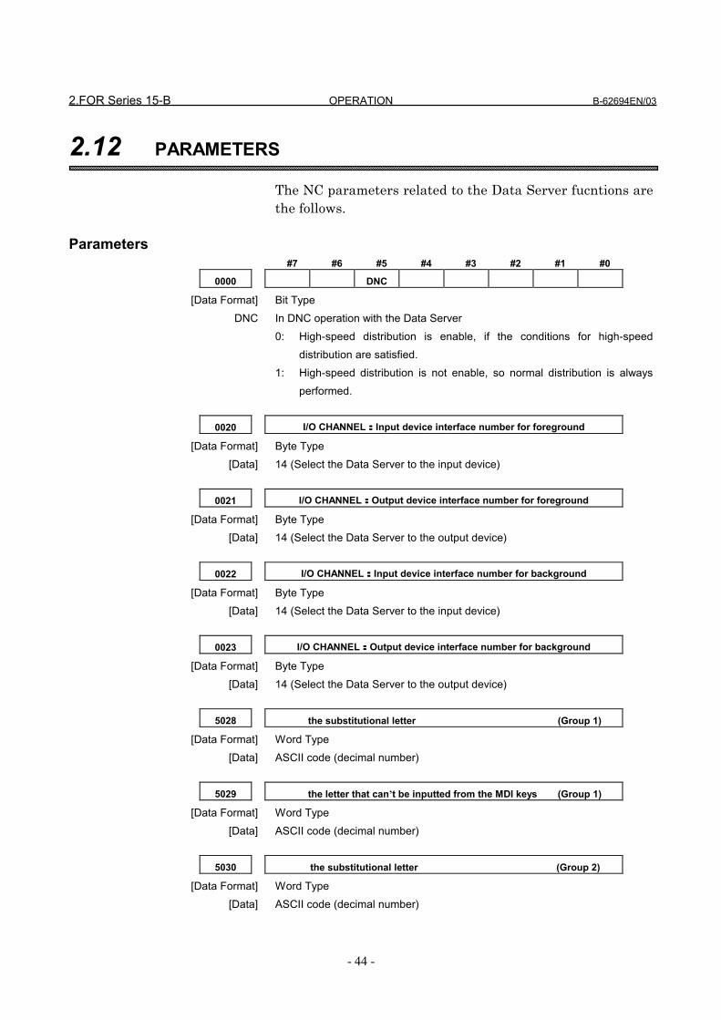
2.FOR Series 15-B OPERATION B-62694EN/03
- 44 -
2.12 PARAMETERS
The NC parameters related to the Data Server fucntions arethe follows.
Parameters#7 #6 #5 #4 #3 #2 #1 #0
0000 DNC
[Data Format] Bit TypeDNC In DNC operation with the Data Server
0: High-speed distribution is enable, if the conditions for high-speeddistribution are satisfied.
1: High-speed distribution is not enable, so normal distribution is alwaysperformed.
0020 I/O CHANNEL::::Input device interface number for foreground
[Data Format] Byte Type[Data] 14 (Select the Data Server to the input device)
0021 I/O CHANNEL::::Output device interface number for foreground
[Data Format] Byte Type[Data] 14 (Select the Data Server to the output device)
0022 I/O CHANNEL::::Input device interface number for background
[Data Format] Byte Type[Data] 14 (Select the Data Server to the input device)
0023 I/O CHANNEL::::Output device interface number for background
[Data Format] Byte Type[Data] 14 (Select the Data Server to the output device)
5028 the substitutional letter (Group 1)
[Data Format] Word Type[Data] ASCII code (decimal number)
5029 the letter that can’t be inputted from the MDI keys (Group 1)
[Data Format] Word Type[Data] ASCII code (decimal number)
5030 the substitutional letter (Group 2)
[Data Format] Word Type[Data] ASCII code (decimal number)

B-62694EN/03 OPERATION 2.FOR Series 15-B
- 45 -
5031 the letter that can’t be inputted from the MDI keys (Group 2)
[Data Format] Word Type[Data] ASCII code (decimal number)
5032 the substitutional letter (Group 3)
[Data Format] Word Type[Data] ASCII code (decimal number)
5033 the letter that can’t be inputted from the MDI keys (Group 3)
[Data Format] Word Type[Data] ASCII code (decimal number)
The above NC parameters from No.5028 to No.5033 are usedin order to substitute the letter that can be inputted from theMDI keys for the letter that can’t be inputted from the MDIkeys, when you set the HOST DIRECTORY at the “DATASERVER SETTING-1” screen.There are three pairs. One pair is No.5028 and No.5029, theother is No.5030 and No.5031, the last is No.5032 andNo.5033.And the last pair , No.5032 and No.5033, is used for settingnot only the HOST DIRECTORY but also the file name thatis transferred between the Host Computer and the DataServer.
Example)If you wish to set “C:¥DTSVR¥NC_PROG” to the HOSTDIRECTORY, you can’t input “¥”, “:” and “_” from the MDIkeys. So, you may substitute “@” for “:”, “/” for “¥” and “-”for “_”.In this case, you set the NC parameters as follows.
No.5028 64 ( ASCII code of “@”, decimal number )No.5029 58 ( ASCII code of “:”, decimal number )No.5030 47 ( ASCII code of “/”, decimal number )No.5031 92 ( ASCII code of “¥”, decimal number )No.5032 45 ( ASCII code of “-”, decimal number )No.5033 95 ( ASCII code of “_”, decimal number )
Afterward, set “C@/DTSVR/NC-PROG” in the HOSTDIRECTORY on the “DATA SERVER SETTING-1” screenand press the softkey [ SET ].Then the Data Server’s software changes it into“C:¥DTSVR¥NC_PROG” and saves the changed string.

2.FOR Series 15-B OPERATION B-62694EN/03
- 46 -
When you want to get “nc_file1” file in the Host Computerinto the HDD as named “O1234” by using “GET” commandof FTP, you specify “O1234,nc-file1”.In this case, the Data Server’s software changes “nc-file1”into “nc_file1” and get “nc_file1” from the Host Computerto the HDD.
NOTE1 If the both NC parameters No.5028 and No.5029 are equal
to 0, then the NC parameters are considered to be set asfollows.No.5028 = 32 (space)No.5029 = 92 (“¥”)
2 If the both NC parameters No.5030 and No.5031 are equalto 0, then the NC parameters are considered to be set asfollows.No.5030 = 64 (“@”)No.5031 = 58 (“:”)
3 The NC parameters No.5032 and No.5033 don’t havedefault values.
4 In these three pairs, the smaller pair is availablepreferencially. That is to say, if the same value is set inNo.5028, No.5030 and No.5032, the pair of No.5028 andNo.5029 is available.
5 In case of displaying the “DATA SERVER SETTING”screen, the Data Server’s software exchanges the letters inreverse and displays the setting data.

B-62694EN/03 OPERATION 2.FOR Series 15-B
- 47 -
2.13 ALARMS
The system alarms related to the Data Server fucntions areshown below.
Number Message displayed on CRT ContentsSR910 DATA SERVER SERIOUS
ERRORIn the Data Server, theserious error occurred.It is necessary to turn offand on the power.
SR911 DATA SERVER APPLICATIONERROR
In the Data Server, theapplication error occurred.Investigate the cause ofthis error, and execute acorrect operation.
CAUTIONIf the above alarm is displayed, please confirm thedescription in “2.11 ERROR MESSAGE” and remove theerror.

APPENDIX

B-62694EN/03 APPENDIX A. TABLE OF ERROR MESSAGES
-1-
A TABLE OF ERROR MESSAGES
In this appendix A, the contents of error messages that aredisplayed in the “DATA SERVER MESSAGE-1” screen areexplained in detail.These error messages are common for all CNCs.Some messages may be displayed for one service.
These error messages are classified by three letters at the topof message. Refer to the following.[LCL] : Internal service when turning on the power[FCB] : Internal service when turning on the power[MNT] : Internal service when turning on the power[DWN] : Download (Calling a subprogram with M198,
DNC operation, and Registering a NC program)[UP ] : Upload (Outputting a NC program)[BUF] : Download on the buffer mode[MOD] : Changing the mode[GET] : Getting a NC program[PUT] : Putting a NC program[DEL] : Deleting NC programs[DIR] : Displaying the table of NC programs,
Searching a NC program[RST] : Displaying the setting data[WST] : Setting the setting data[FMT] : Formatting the built-in hard disk[CHK] : Checking the built-in hard disk[LGT] : List-Getting NC programs[LPT] : List-Putting NC programs[LDE] : List-Deleting NC programs
All error messages are not described in this appendix A.So, the other message may be displayed in the “DATASERVER MESSAGE-1” screen.

A. TABLE OF ERROR MESSGES APPENDIX B-62694EN/03
-2-
ERROR MESSAGES WHEN TURNING ON THE POWER[LCL] INVALID MAC ADDRESS(xxxxxxxxxxxx)
The specified MAC address (xxxxxxxxxxxx) is unavailable.Input the 12 alphanumerical letters printed as the “ADR”atthe seal on the Data Server board. Then turn off and on thepower.When you turn on the power for the first time and the settingdata are not set, this error message is displayed, too.
[LCL] OPEN (/tmp/ncprog.tmp) ERROR(ddd)Fail to open the file for managing NC programs in the HDD.The error code is (ddd).When you turn on the power for the first time and the HDDis not formatted, this error message may be displayed. Pleaseformat the HDD.
[LCL] OPEN (/tmp/setting.tbl) ERROR(ddd)Fail to open the file which the setting data are saved in. Theerror code is (ddd).When you turn on the power for the first time and the settingdata are not set, this error message may be displayed. Pleaseset the setting data.
[LCL] SETUP FTP ERROR(ddd)Fail to setup the FTP function. The error code is (ddd).Please confirm whether the setting data are correct.
[LCL] CHANGE DIRECTORY ERROR[FCB] CHANGE DIRECTORY ERROR[MNT] CHANGE DIRECTORY ERROR
Fail to change the local directory.Please confirm whether there is abnormal sector in the HDDby checking the HDD.If there is abnormal sector, please format the HDD.
[MNT] CREATE DIRECTORY(xxxxx) ERRORFail to create the directory(xxxxx). Please format the HDD.
[MNT] CREATE (/tmp/common.ram) ERROR(0)When turning on the power, fail to create the reserved file.When you turn on the power for the first time and the HDDis not formatted, this error message may be displayed. Pleaseformat the HDD.
ERROR MESSAGES FOR DOWNLOAD[DWN] (Oxxxx) IS IN USE The specified NC program (Oxxxx) is in use by other service.
Retry after other service will finish.[DWN] (Oxxxx) DOESN’T EXIST

B-62694EN/03 APPENDIX A. TABLE OF ERROR MESSAGES
-3-
The specified NC program doesn’t exist in the HDD.Please confirm that the NC program exists in the HDD byusing “Searching a NC program”.
[DWN] HDD IS IN USE The HDD is in use by other service.Retry after other service will finish.
ERROR MESSAGES FOR DOWNLOAD ON THE BUFFER MODE[BUF] OPERATING ON THE BUFFER MODE
When the CNC is processing the work on the buffer mode,you would operate the NC program management functions.You can’t operate the NC program management functionswhen the CNC is processing the work. Therefore, retry afterthe CNC will finish processing it.
[BUF] LOCAL REQUEST IS BUSY The NC program management function is in use by otherservice, so that the CNC can’t run on the buffer mode.Retry after other service will finish.
[BUF] GET FILE LIST ERRORIn case of the buffer mode, fail to get the list of files.Please confirm that the Data Server can communicate withthe Host Computer correctly or that the specified file isregistered in the Host Computer.
[BUF] FTP IS BUSY In case of the buffer mode, when it was finished to transfer apart of the NC program in one area, the continuous partwasn’t got into another area by the “GET” command of theFTP yet.Please confirm the size of the divided files.
ERROR MESSAGES FOR UPLOAD[UP ] (Oxxxx) IS IN USE The specified NC program (Oxxxx) is in use by other service.
Retry after other service will finish.[UP ] (Oxxxx) EXISTS The specified NC program (Oxxxx) already exists in the
HDD.Retry after deleting the NC program from the HDD.
[UP ] HDD IS IN USE The HDD is in use by other service.Retry after other service will finish.
[UP ] CREATE (/tmp/ncprog.tmp) ERROR(0)Fail to create the file for managing NC programs in the HDD.Please confirm the remained area of the HDD.
ERROR MESSAGES FOR CHANGING THE MODE[MOD] CHANGE MODE ERROR
Fail to change the mode. Please check the HDD and confirmwhether the HDD is available.

A. TABLE OF ERROR MESSGES APPENDIX B-62694EN/03
-4-
[MOD] HDD IS IN USE The HDD is in use by other service.Retry after other service will finish.
ERROR MESSAGES FOR GETTING A NC PROGRAM[GET] FTP IS NOT READY It is not ready for using the FTP.
Confirm the setting data and then turn off and on the power.If the setting data is not set correctly, the Data Server can’tcommunicate with the Host Computer.
[GET] (Oxxxx) IS IN USE The specified NC program (Oxxxx) is in use by other service.Retry after other service will finish.
[GET] (Oxxxx) EXISTS The specified NC program (Oxxxx) already exists in theHDD.Retry after deleting the NC program from the HDD.
[GET] CREATE (/tmp/ncprog.tmp) ERROR(0)Fail to create the file for managing NC programs in the HDD.Please confirm the remained area of the HDD.
[GET] FTP ERROR(ddd) An error occurs when executing the “GET” command of theFTP. The error code is (ddd).When this error occurs, other error message is displayed. So,investigate other error message.
[GET] ftp: connect: Connection timed outThere is no response of the Host Computer from “GET”command of the Data Server.Check the connection of the Ethernet cable and the settingdata.
[GET] ftp: connect: No route to hostCheck the IP address and MASK address in the setting data.In case that the Network address part of the HostComputer’s IP Address is different from the Data Server’sone, this error occurs.
[GET] ddd : xxxxxxxxxxxxxxxxxxxxxAn error occurs in the Host Computer when executing the“GET” command of the FTP. This error message is sent fromthe Host Computer mainly.The error code is “ddd” and the error message is “xxxxxxxx”.The error message depends on the Host Computer. And whendisplaying this error message, display the command too.Retry after removing the causes of this error by referring tothe manual for the Host Computer.Show the meaning of the principal errors as follows.Error Code : Meaning
450 : The specified file is in use by other process inthe Host Computer.Confirm whether the specified file is used by

B-62694EN/03 APPENDIX A. TABLE OF ERROR MESSAGES
-5-
other process.530 : Fail to login to the Host Computer.
Check “USER NAME” and “PASSWORD” inthe setting data.
550(553) : The specified directory or file is not found inthe Host Computer.Check “HOST DIRECTORY” in the settingdata and the specified file name.
ERROR MESSAGES FOR PUTTING A NC PROGRAM[PUT] FTP IS NOT READY It is not ready for using the FTP.
Confirm the setting data and then turn off and on the power.If the setting data is not set correctly, the Data Server can’tcommunicate with the Host Computer.
[PUT] (Oxxxx) IS IN USE The specified NC program (Oxxxx) is in use by other service.Retry after other service will finish.
[PUT] (Oxxxx) DOESN’T EXISTThe specified NC program doesn’t exist in the HDD.Please confirm that the NC program exists in the HDD byusing “Searching a NC program”.
[PUT] FTP ERROR(ddd) An error occurs when executing the “GET” command of theFTP. The error code is (ddd).When this error occurs, other error message is displayed. So,investigate other error message.
[PUT] ftp: connect: Connection timed outThere is no response of the Host Computer from “PUT”command of the Data Server.Check the connection of the Ethernet cable and the settingdata.
[PUT] ftp: connect: No route to hostCheck the IP address and MASK address in the setting data.In case that the Network address part of the HostComputer’s IP Address is different from the Data Server’sone, this error occurs.
[PUT] ddd : xxxxxxxxxxxxxxxxxxxxxAn error occurs in the Host Computer when executing the“PUT” command of the FTP. This error message is sent fromthe Host Computer mainly.The error code is “ddd” and the error message is “xxxxxxxx”.The error message depends on the Host Computer. And whendisplaying this error message, display the command too.Retry after removing the causes of this error by referring tothe manual for the Host Computer.Refer to “ERROR MESSAGES FOR GETTING A NC

A. TABLE OF ERROR MESSGES APPENDIX B-62694EN/03
-6-
PROGRAM” about the error message.
ERROR MESSAGES FOR DELETING NC PROGRAMS[DEL] (Oxxxx) IS IN USE The specified NC program (Oxxxx) is in use by other service.
Retry after other service will finish.[DEL] (Oxxxx) IS NOT FOUND(ddd)
The specified NC program (Oxxxx) doesn’t exist in the HDD.The error code is (ddd).Please confirm that the NC program exists in the HDD byusing “Searching a NC program”.
ERROR MESSAGES FOR LIST-GETTING NC PROGRAMS[LGT] FTP IS NOT READY It is not ready for using the FTP.
Confirm the setting data and then turn off and on the power.If the setting data is not set correctly, the Data Server can’tcommunicate with the Host Computer.
[LGT] (Oxxxx) IS IN USE The specified NC program (Oxxxx) is in use by other service.Retry after other service will finish.
[LGT] (Oxxxx) EXISTS The specified NC program (Oxxxx) already exists in theHDD.Retry after deleting the NC program from the HDD.
[LGT] LIST FORMAT ERRORThere is a mistake in the contents of the List-File.Check the contents of the List-File.
[LGT] INVALID LIST FOUND(xxxxx)The unrecognized list (xxxxx) is found.Check the contents of the List-File.
[LGT] SAME FILE FOUND(Oxxxx)The same NC program is found in the List-File.You can’t specify the same NC program repeatedly.
[LGT] CREATE (/tmp/ncprog.tmp) ERROR(0)Fail to create the file for managing NC programs in the HDD.Please confirm the remained area of the HDD.
[LGT] FTP ERROR(ddd) An error occurs when executing the “GET” command of theFTP. The error code is (ddd).When this error occurs, other error message is displayed. So,investigate other error message.
[LGT] ftp: connect: Connection timed outThere is no response of the Host Computer from “GET”command of the Data Server.Check the connection of the Ethernet cable and the settingdata.
[LGT] ftp: connect: No route to hostCheck the IP address and MASK address in the setting data.

B-62694EN/03 APPENDIX A. TABLE OF ERROR MESSAGES
-7-
In case that the Network address part of the HostComputer’s IP Address is different from the Data Server’sone, this error occurs.
[LGT] ddd : xxxxxxxxxxxxxxxxxxxxxAn error occurs in the Host Computer when executing the“List-Get” service. This error message is sent from the HostComputer mainly.The error code is “ddd” and the error message is “xxxxxxxx”.The error message depends on the Host Computer. And whendisplaying this error message, display the command too.Retry after removing the causes of this error by referring tothe manual for the Host Computer.Refer to “ERROR MESSAGES FOR GETTING A NCPROGRAM” about the error message.
ERROR MESSAGE FOR LIST-PUTTING NC PROGRAMS[LPT] FTP IS NOT READY It is not ready for using the FTP.
Confirm the setting data and then turn off and on the power.If the setting data is not set correctly, the Data Server can’tcommunicate with the Host Computer.
[LPT] (Oxxxx) IS IN USE The specified NC program (Oxxxx) is in use by other service.Retry after other service will finish.
[LPT] (Oxxxx) DOESN’T EXISTThe specified NC program doesn’t exist in the HDD.Please confirm that the NC program exists in the HDD byusing “Searching a NC program”.
[LPT] LIST FORMAT ERRORThere is a mistake in the contents of the List-File.Check the contents of the List-File.
[LPT] INVALID LIST FOUND(xxxxx)The unrecognized list (xxxxx) is found.Check the contents of the List-File.
[LPT] SAME FILE FOUND(Oxxxx)The same NC program is found in the List-File.You can’t specify the same NC program repeatedly.
[LPT] FTP ERROR(ddd) An error occurs when executing the “PUT” command of theFTP. The error code is (ddd).When this error occurs, other error message is displayed. So,investigate other error message.
[LPT] ftp: connect: Connection timed outThere is no response of the Host Computer from “PUT”command of the Data Server.Check the connection of the Ethernet cable and the settingdata.

A. TABLE OF ERROR MESSGES APPENDIX B-62694EN/03
-8-
[LPT] ftp: connect: No route to hostCheck the IP address and MASK address in the setting data.In case that the Network address part of the HostComputer’s IP Address is different from the Data Server’sone, this error occurs.
[LPT] ddd : xxxxxxxxxxxxxxxxxxxxxAn error occurs in the Host Computer when executing the“List-Put” service. This error message is sent from the HostComputer mainly.The error code is “ddd” and the error message is “xxxxxxxx”.The error message depends on the Host Computer. And whendisplaying this error message, display the command too.Retry after removing the causes of this error by referring tothe manual for the Host Computer.Refer to “ERROR MESSAGES FOR GETTING A NCPROGRAM” about the error message.
ERROR MESSAGES FOR LIST-DELETING NC PROGRAMS[LDE] (Oxxxx) IS IN USE The specified NC program (Oxxxx) is in use by other service.
Retry after other service will finish.[LDE] (Oxxxx) IS NOT FOUND(ddd)
The specified NC program (Oxxxx) doesn’t exist in the HDD.The error code is (ddd).Please confirm that the NC program exists in the HDD byusing “Searching a NC program”.
[LDE] LIST FORMAT ERRORThere is a mistake in the contents of the List-File.Check the contents of the List-File.
[LDE] INVALID LIST FOUND(xxxxx)The unrecognized list (xxxxx) is found.Check the contents of the List-File.
[LDE] SAME FILE FOUND(Oxxxx)The same NC program is found in the List-File.You can’t specify the same NC program repeatedly.
ERROR MESSAGES FOR DISPLAYING TABLE OF NC PROGRAMS[DIR] HDD INFO. ERROR(ddd)
Fail to get the information of the HDD. The error code is(ddd).Check the HDD and confirm whether there is a problem inthe HDD.
[DIR] (Oxxxx) IS NOT FOUNDThe NC program (Oxxxx) that is registered in the NCprogram management file doesn’t exist in the HDD.
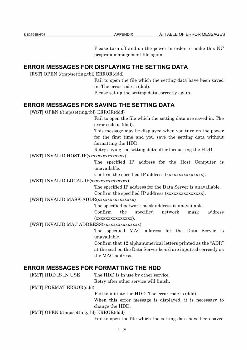
B-62694EN/03 APPENDIX A. TABLE OF ERROR MESSAGES
-9-
Please turn off and on the power in order to make this NCprogram management file again.
ERROR MESSAGES FOR DISPLAYING THE SETTING DATA[RST] OPEN (/tmp/setting.tbl) ERROR(ddd)
Fail to open the file which the setting data have been savedin. The error code is (ddd).Please set up the setting data correctly again.
ERROR MESSAGES FOR SAVING THE SETTING DATA[WST] OPEN (/tmp/setting.tbl) ERROR(ddd)
Fail to open the file which the setting data are saved in. Theerror code is (ddd).This message may be displayed when you turn on the powerfor the first time and you save the setting data withoutformatting the HDD.Retry saving the setting data after formatting the HDD.
[WST] INVALID HOST-IP(xxxxxxxxxxxxxxx)The specified IP address for the Host Computer isunavailable.Confirm the specified IP address (xxxxxxxxxxxxxxx).
[WST] INVALID LOCAL-IP(xxxxxxxxxxxxxxx)The specified IP address for the Data Server is unavailable.Confirm the specified IP address (xxxxxxxxxxxxxxx).
[WST] INVALID MASK-ADDR(xxxxxxxxxxxxxxx)The specified network mask address is unavailable.Confirm the specified network mask address(xxxxxxxxxxxxxxx).
[WST] INVALID MAC ADDRESS(xxxxxxxxxxxxxxx)The specified MAC address for the Data Server isunavailable.Confirm that 12 alphanumerical letters printed as the “ADR”at the seal on the Data Server board are inputted correctly asthe MAC address.
ERROR MESSAGES FOR FORMATTING THE HDD[FMT] HDD IS IN USE The HDD is in use by other service.
Retry after other service will finish.[FMT] FORMAT ERROR(ddd)
Fail to initiate the HDD. The error code is (ddd).When this error message is displayed, it is necessary tochange the HDD.
[FMT] OPEN (/tmp/setting.tbl) ERROR(ddd)Fail to open the file which the setting data have been saved
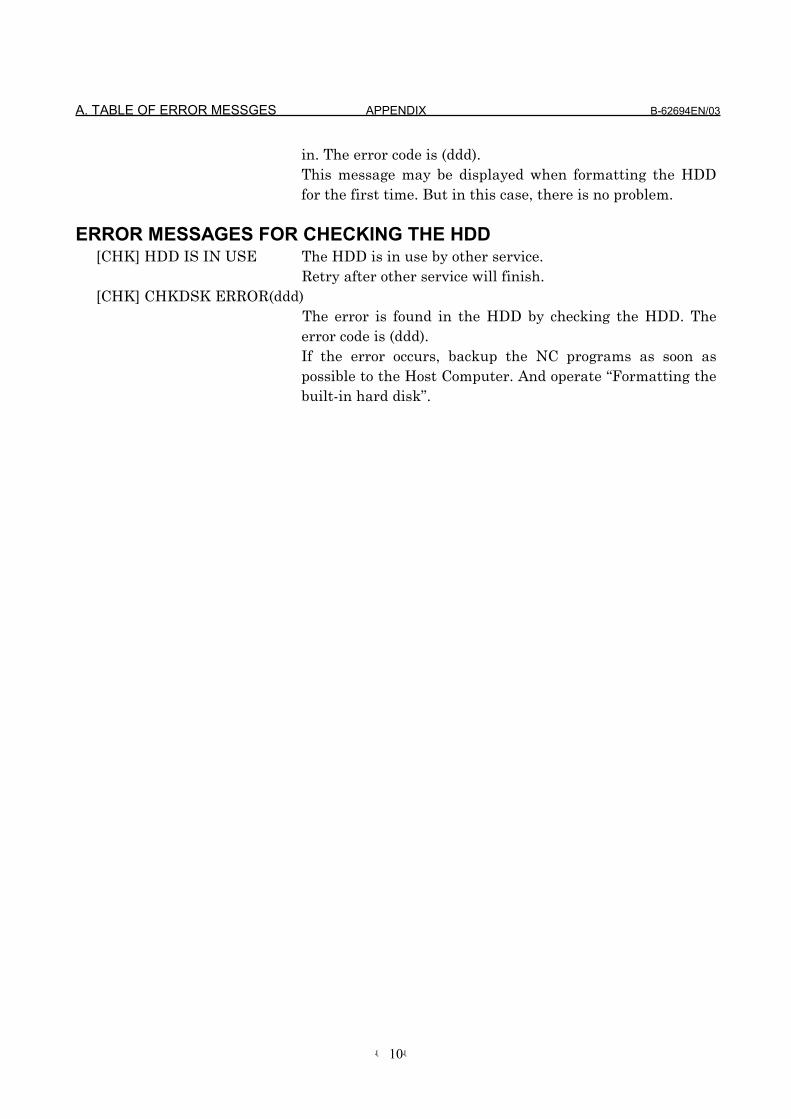
A. TABLE OF ERROR MESSGES APPENDIX B-62694EN/03
-10-
in. The error code is (ddd).This message may be displayed when formatting the HDDfor the first time. But in this case, there is no problem.
ERROR MESSAGES FOR CHECKING THE HDD[CHK] HDD IS IN USE The HDD is in use by other service.
Retry after other service will finish.[CHK] CHKDSK ERROR(ddd)
The error is found in the HDD by checking the HDD. Theerror code is (ddd).If the error occurs, backup the NC programs as soon aspossible to the Host Computer. And operate “Formatting thebuilt-in hard disk”.

B-62694EN/03 APPENDIX B. SERIOUS ERROR
-11-
B SERIOUS ERROR
In this appendix B, the contents of error messages that aredisplayed in the “DATA SERVER MESSAGE-2” screen areexplained in detail.These error messages are common at all CNCs.If the following error message is displayed in the “DATASERVER MESSAGE-2” screen, the Data Server can’t workcontinuously. In this case, check the Data Server’s LEDs’status and investigate the cause of the error at the section“3.2 Lighting of LEDs and meaning” of the chapter “II.MAINTENANCE”.

B. SERIOUS ERROR APPENDIX B-62694EN/03
-12-
B.1 THE IMAGE OF SCREEN
The contents of screens are as follows.
(1) In case that error_address and stack_bump offset are16bits
(2) In case that error_address and stack_bump offset are
32bits
DATA-SERVER SYSTEM ROM nnnn [X] yy/mm/ddCPU : GENERAL PROTECTION
0000 0000 0000 0000 0000 0000 0000 000000000000 00000000 00000000 0000000000000000 00000000 00000000 0000000000000000 00000000
0000 0000:000000000000 0000:00000000 0000 0000 0000 0000 0000 0000 00000000 0000 0000 0000 0000 0000 0000 0000
DATA-SERVER SYSTEM ROM nnnn [X] yy/mm/ddCPU : GENERAL PROTECTION
0000 0000 0000 0000 0000 0000 0000 000000000000 00000000 00000000 0000000000000000 00000000 00000000 0000000000000000 00000000
0000 0000:0000000000000000 0000:000000000000 0000 0000 0000 0000 0000 0000 00000000 0000 0000 0000 0000 0000 0000 0000

B-62694EN/03 APPENDIX B. SERIOUS ERROR
-13-
B.2 THE CONTENTS OF SCREEN
Each line means as follows,
(1) 1st line : Revision of the Data Server’s firmware nnnn : Series number of the Data Server’s firmware In case of Series 16/18-B/C, Series 15-B : 6535 In case of Series 16i/18i-A : 6537 is displayed. [X] : Revision number of the Data Server’s firmware The Revision from A to Z is displayed. yy/mm/dd : Created date is displayed. (2) 2nd line : Kind of the error The serious error has “NMI error” and “CPU error”. “NMI error” occurs mainly for the hardware trouble. If it
occurs, confirm the connection of modules and LEDs’status.
“CPU error” occurs mainly for the software trouble. If itoccurs, contact FANUC.
The error messages are shown as follows. NMI errors :
NMI : F-BUS BUS ERROR NMI : SYSTEM EMERGENCY NMI : REFRESH CYCLE ABORT NMI : DRAM PARITY ERROR NMI : SRAM PARITY ERROR NMI : COMMON RAM PARITY ERROR NMI : UNIDENTIFIED NMI
CPU errors :
CPU : GENERAL PROTECTION CPU : INVALID OPCODE CPU : STACK FAULT CPU : DIVIDE ERROR CPU : DEBUG EXCEPTION CPU : BREAKPOINT CPU : OVERFLOW CPU : BOUND RANGE EXCEEDED CPU : DOUBLE FAULT CPU : COPROCESSOR SEGMENT OVERRUN CPU : INVALID TSS CPU : SEGMENT NOT PRESENT CPU : PAGE FAULT CPU : COPROCESSOR ERROR
B. SERIOUS ERROR APPENDIX B-62694EN/03
-14-
(3) latter than 4th line : contents of registers Show the contents of CPU’s registers. The information is
necessary to investigate the trouble. So, when you contactFANUC, please tell us these contents exactly.
B-62694EN/03 APPENDIX C. ETHERNET TECHNICAL TERMS
-15-
C ETHERNET TECHNICAL TERMS
In this appendix C, the main Ethernet technical terms areexplained briefly.If you will study more, refer to the literature on the market.

C. ETHERNET TECHNICAL TERMS APPENDIX B-62694EN/03
-16-
TCP/IPIn the communication by using the Ethernet, TCP/IP(Transmission Control Protocol/Internet Protocol) is usedusually. “Protocol” means the rule to connect between thecommunication devices. TCP/IP is a part of the followinglayer.
Layer Protocols, Network ServicesApplication Layer User Services as “FTP”Transport Layer Protocols as “TCP”, “UDP”Network Layer Protocols as “IP”, “ICMP”DataLink Layer Protocols as “ARP”, “RARP”
MAC LayerPhysical Layer Hardware as cables, devices
Usually, “TCP/IP” protocol is a generic name including theprotocols in Transport Layer and Network Layer.
IP ADDRESS (INET ADDRESS)In TCP/IP, the address called “IP ADDRESS” is used in orderto identify the communication devices in a network. So, inorder to communicate by using TCP/IP, each device in anetwork must have a unique IP address.Usually IP address is shown as a form separating 4 octetsinto each 1 octet by using “.” (period). Each octet can have avalue from 0 to 255.
IP address consists of the Network address part showing thenetwork group and the Host address part showing the node.IP address can be classified into 3 classes.
Value of top 1 octet Network addresspart
Host address part
CLASS A From 0 to 127 xxx.xxx.xxx.xxx xxx.xxx.xxx.xxxCLASS B From 128 to 191 xxx.xxx.xxx.xxx xxx.xxx.xxx.xxxCLASS C From 192 to 223 xxx.xxx.xxx.xxx xxx.xxx.xxx.xxx
(The underline part is the each address part)
If your network has less than 255 nodes, CLASS C is usedusually.The IP address of the device connected in a network has acommon Network address part and a unique Host address

B-62694EN/03 APPENDIX C. ETHERNET TECHNICAL TERMS
-17-
part.And you can’t set that all octets are equal to 0 or 255 in theNetwork address part and the Host address part.
The IP address is managed worldwide. So, in order to use theIP address you must get the IP address from theinternational organization.
But if your network is a local closed network, you canmanage the IP addresses in your responsibility.And the IP address having the following Network addresspart can be used in a local closed network without permissionfrom the international organization. So, if your network is alocal closed network, we recommend that you use these IPaddresses.
CLASS Network address partCLASS A 10CLASS B From 172.16 to 172.31CLASS C From 192.168.0 to 192.168.255
MASK ADDRESSThis is the mask value for showing the Network address partin the IP address.In case of the CLASS A, you specify “255.0.0.0”.In case of the CLASS B, you specify “255.255.0.0”.In case of the CLASS C, you specify “255.255.255.0”.
MAC ADDRESS (ETHERNET ADDRESS)This address is used in order to distinguish the each devicesin MAC Layer. The maker creating the communicationcontrol board gets the unique MAC address from theinternational organization.In case of Data Server, we affix the seal printed as the “ADR”on the Data Server board. You must set this MAC address tothe Data Server.
HEARTBEAT (SQE TEST) FUNCTIONIn the standard of “Ethernet” or “IEEE802.3”, whentransmitting the data into the network, a node checks thatother devices don’t communicate in the network.If the devices start transmitting the data simultaneously, thecollision of the data occurs. The frequent collision makes thereal transmission rate less.

C. ETHERNET TECHNICAL TERMS APPENDIX B-62694EN/03
-18-
Now, in the standard of “IEEE802.3”, a node checks totransmit the data normally. This function is called the“heartbeat” function.The Data Server board is made according to the standard of“IEEE802.3”, so that this heartbeat function is supported.Therefore, if you connect a tranceiver without this heartbeatfunction, it may make the real transmission rate less becausean error occurs at all times transmitting the data.Then the tranceiver connecting with the Data Server boardmust support this heartbeat function.
SEGMENTOriginally, the extent which is connected by onemedium(cable) physically is called as “segment”. But themeaning of the segment is changing for the 10BASE-T.It is common opinion that the meaning of the segment is “theextent which is act the CSMA/CD function”.
CSMA FUNCTION (Carrier Sense Multiple Access)To transmit, a station waits for a quite period on themedium(cable) (That is, no other station is transmitting) andthe sends the intended message in bit-serial form.
CD FUNCTION (Collision Detect)If after initiating a transmission, the message collides withthat of another station, then each transmitting stationintentionally sends a few additional bytes to ensurepropagation of the collision throughout the system. Thestation remains silent for a random amount of time beforeattempting to transmit again.
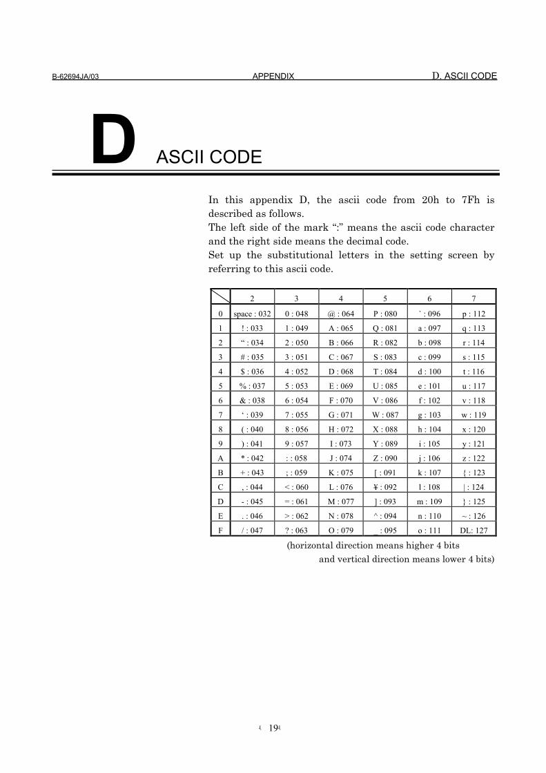
B-62694JA/03 APPENDIX D. ASCII CODE
-19-
D ASCII CODE
In this appendix D, the ascii code from 20h to 7Fh isdescribed as follows.The left side of the mark “:” means the ascii code characterand the right side means the decimal code.Set up the substitutional letters in the setting screen byreferring to this ascii code.
2 3 4 5 6 7
0 space : 032 0 : 048 @ : 064 P : 080 ` : 096 p : 112
1 ! : 033 1 : 049 A : 065 Q : 081 a : 097 q : 113
2 “ : 034 2 : 050 B : 066 R : 082 b : 098 r : 114
3 # : 035 3 : 051 C : 067 S : 083 c : 099 s : 115
4 $ : 036 4 : 052 D : 068 T : 084 d : 100 t : 116
5 % : 037 5 : 053 E : 069 U : 085 e : 101 u : 117
6 & : 038 6 : 054 F : 070 V : 086 f : 102 v : 118
7 ‘ : 039 7 : 055 G : 071 W : 087 g : 103 w : 119
8 ( : 040 8 : 056 H : 072 X : 088 h : 104 x : 120
9 ) : 041 9 : 057 I : 073 Y : 089 i : 105 y : 121
A * : 042 : : 058 J : 074 Z : 090 j : 106 z : 122
B + : 043 ; : 059 K : 075 [ : 091 k : 107 { : 123
C , : 044 < : 060 L : 076 ¥ : 092 l : 108 | : 124
D - : 045 = : 061 M : 077 ] : 093 m : 109 } : 125
E . : 046 > : 062 N : 078 ^ : 094 n : 110 ~ : 126
F / : 047 ? : 063 O : 079 _ : 095 o : 111 DL: 127
(horizontal direction means higher 4 bits
and vertical direction means lower 4 bits)

• No part of this manual may bereproduced in any form.
• All specifications and designsare subject to change withoutnotice.