ge inspection technologies range of ct systems and
TRANSCRIPT

GE Inspection Technologies Range of CT Systems and Applications
Don RothRadiography Applications Leader, North
AmericaGEIT
Acknowledgements: Stephen D. Rice, Steve Zahorodny, Shana Telesz, Thomas Mayer, Anjali Singhal, Ying Zhou, Vance
Robinson

Outline
• Range of Systems Overview & GEIT News
• Applications
• Automating CT for Production Environments and Incorporating Scatter Correction

X-ray Computed Tomography

Range of Volumetric CT Systems Overview

Additional 2D/3D Systems

GEIT Customer Solution Center Mission: The CSC will be the hub for NA customer engagement and drive collaboration for NDT solutions
Host targeted training courses and
forums
Training
Collaboration space to evaluate
customer challenges
Consultative Selling
Drive production solutions for Aero &
Auto customers
SolutionsDevelopment
Growing customer base in additive, composites, and
castings
Thought Leadership
Demonstrate latest GEIT hardware and software offerings
ProductShowcase

Advancements
• High Flux X-ray Target– 2x increase in photon flux at same power as W target
– Or for microCT, allows increase in resolution (decrease in power / spot size) at same photon flux as W target
• Scatter | Correct– Achieve scatter reduction on par w linear CT
• Industrial Helical CT
• Dynamic 41|100 Digital Area Detector– 16” x 16” area with 100um pixel pitch or 200 um pixel pitch
options
– ~ 2x Higher frame rate than current DXR250RT++ panel

Recent NanoCT Results

Recent NanoCT ResultsManaging Tailings is one of the most difficult environmental challenges facing the oil sands industry
Large volumes of tailings are a byproduct of bitumen extraction from the oil sands

Recent NanoCT Results
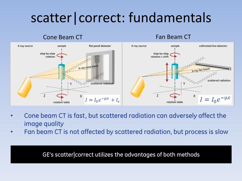
scatter|correct: fundamentals
• Cone beam CT is fast, but scattered radiation can adversely affect the image quality
• Fan beam CT is not affected by scattered radiation, but process is slow
GE’s scatter|correct utilizes the advantages of both methods
Cone Beam CT Fan Beam CT

CT slice without scatter|correct CT slice with scatter|correct
scatter|correct: Al test block example
• Improved gray value homogeneity• Improved metrology performance
ASNT Conference 2016
• 12

scatter|correct technology: the imaging results
1. 9 min Cone beam CT image with imaging artifacts caused
by scatter2. 120 min Fan beam CT image without imaging artifacts3. scatter|correct: speed of cone beam CT (9 min) combined
with the quality of fan beam CT
1. 2. 3.

CT slice without scatter|correct CT slice with scatter|correct
scatter|correct: CT Results on Turbine Blade

scatter|correct: Aluminum Die Casting
CT slice without scatter|correct
scatter|correct

CT slice without scatter|correct CT slice with scatter|correct
scatter|correct: Aluminum Die Casting Example
• scatter|correct allows less blur & streaks
• A much higher gray value homogeneity
• Improved defect detection & metrology

CT histogram without scatter|correct CT histogram with scatter|correct
scatter|correct: Aluminum Die Casting Example

CT slice without scatter|correct CT slice with scatter|correct
scatter|correct: multi-material sample (Al, Steel, Plastic)
• scatter|correct allows less blur & streaks • Higher gray value homogeneity• Improved defect detection & metrology • Better qualitative and quantitative analysis
ASNT Conference 2016
• 18
Steel
AlPlastic
Air
Plastic
Steel
Al

scatter|correct: capability summary
• scatter|correct combines the productivity of 3D CT with the data quality of 2D CT
• 3D cone beam CT is up to 100 x faster than 2D fan beam CT
• scatter|correct provides high image quality at moderate energies compared to conventional 3D CT
• A unique option for v|tome|x c & v|tome|x m
scatter|correct 3D CT
conventional 3D CT
Fan beam 2D CT
Acquisition speed
CT
Qu
alit
y
ASNT Conference 201619
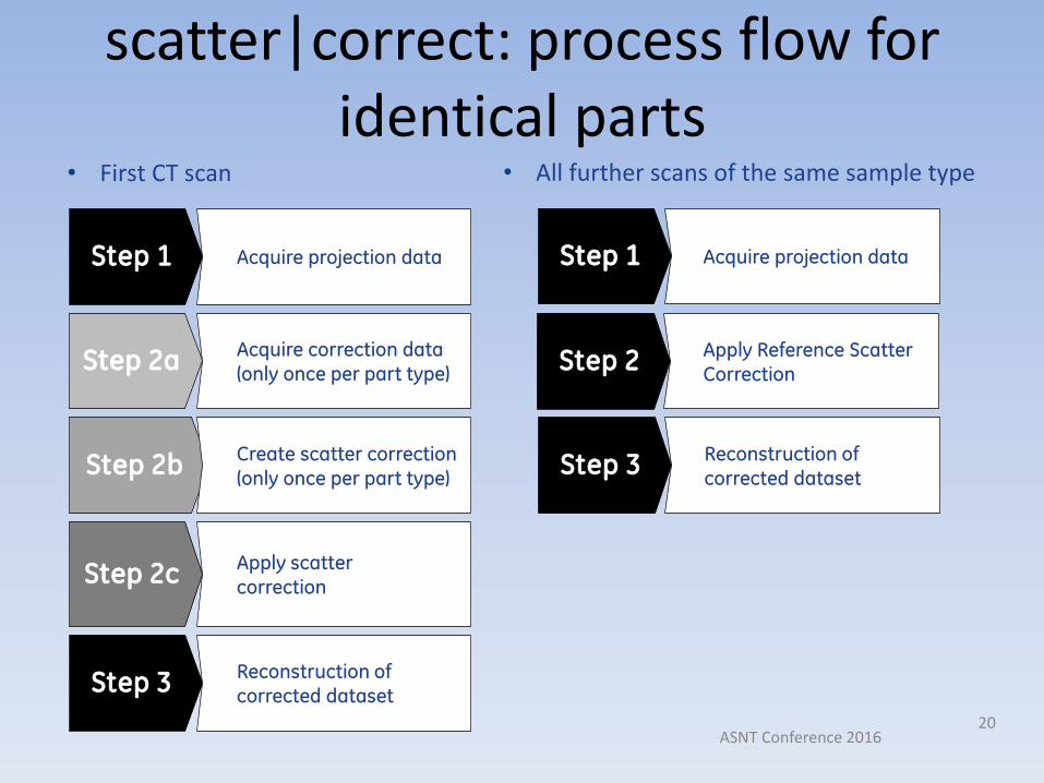
scatter|correct: process flow for identical parts
Step 1 Acquire projection data
Step 2a Acquire correction data(only once per part type)
Step 2c Apply scatter correction
Step 3 Reconstruction of corrected dataset
Step 1
Step 3
Acquire projection data
Reconstruction of corrected dataset
• First CT scan • All further scans of the same sample type
ASNT Conference 201620
Step 2b Create scatter correction(only once per part type)
Step 2 Apply Reference Scatter Correction

Automating CT for Production and Incorporating Scatter Correction – From the Software Side
• V|tome|x CT Products
• DATOS Acquisition and Reconstruction Software
• Macros can be built in Batch Editor
and Executed in Production Mode
• Actions for Xray and Motion Control, Detector Calibration, CT Scan, Delays, Technique File Load, Reconstruction
• Operator only has to load sample, scan barcode of part and badge, and click ‘start execution’ for scan, reconstruction, and data display to be automatically performed

scatter|correct: Recipe for Non-identical parts and first scans for
identical parts
Detector Calibration Offset
Xray OFF
Move Scatter Grid Down Out of Detector Field
Detector Calibration Gain
Move Stage w Part Out of Detector Field
Move Part to Acquire Position
Load Previously-Determined Technique File
Wait 10s for System to Stabilize
Perform CT Scan 1
Xray Off
Repeat 1 for CT Scan 2 butWith Scatter Grid Up for Reference Scatter Grid Scan
1
2
Create Scatter Correction
4
3
Move Stage w Part Out of Detector Field
Wait 1 minute for Detector to Discharge
Obtain Image of Grid Only for Reference Grid Image
Apply Scatter Correction & Reconstruct
4
Xray On

Automating CT for Production• Acquisition Side – Batch Editor
Example for ScatterCorrection on As-MoldedPart or for first time runningScatter correction on setOf identical parts
All Steps Listed

Automating CT for Production
Individual Step Example Showing Parameters that need to be set
Take Bright Field (Gain) Images for Calibration
• Acquisition Side
kV Level for Cal and # of steps
mA Level for Cal

Automating CT for Production• Reconstruction Side – Batch Editor
First Perform Scatter Correction Math
Then Apply it to Projection Images and Perform Reconstruction with Scatter-corrected Projection Images
Scatter-Correction

Automating CT for Production
Individual Step Example Showing Parameters that need to be set
Apply Scatter Correction and Reconstruction
• Reconstruction Side
Beam Hardening Artifact Correction Value
Reconstruction Area

Automating CT for Production• Reconstruction Side
Macros Allow For Launch of External Programs• ImageJ Program to make
AVIs of CT slice stacks• Launch VG or AVIZO for CT
Data Display• Automated Archiving of CT
Data to NAS using LabVIEW
IMAGEJ Code
VG Studio Max

Automating CT for Production• Acquisition Side –
Subsequent Scans of Identical Parts
• Reduced number of acquisition tasks from 30 to 13

Automating CT for Production• Running in Production Mode