gear coupling type re - amazon web services · gear coupling type re ... maina go..a fachin if.. h...
TRANSCRIPT

ITALIANO
Codice 15151 - 10/2006
s.r.l.
MILANO
ITALY
Codice 15418 - 2008
GEAR COUPLING Type RE
Type AR
s.r.l. - Via Monte Rosa, 14 - 20149 MILANO (Italy) - Tel. 02.76.11.03.19 r.a. - Fax 02.76.11.00.41 - E-mail: [email protected] - www.westcar.it

COUPLING TYPE SERIES CONFIGURATION
RE COUPLING WITH STANDARD HUBS
RE UU COUPLING WITH EXTENDED HUBS
RE FOO RIGID COUPLING
RE FO SEMI RIGID COUPLING
RE V VERTICAL COUPLING
RE FT AXIALLY ADJUSTABLE COUPLING
RE D COUPLING WITH SPACER
RE B COUPLING WITH FLOATING SHAFT
RE M SLEEVE COUPLING M SERIE
RE MC SLEEVE COUPLING MC SERIE
RE DH.MN RE DH.PM
RELEASE COUPLING
Cod. 15874 sheet 10-153

PRODOTTI WESTCAR
MILANO
ITALY
WESTCAR PRODUCTS
ROTOFLUID hydraulic
couplings for rated power
up to 4000 kW
ROTOGEAR tooth gear
couplings
for torques up to 383.000 Nm
ROTOFLUID GGG
hydraulic couplings
(with cast-iron casing) for rated
power from 100 to 6000 kW
ROTOFLEXI® flexible
couplings with quick
replacement of the rubber
element without axial hubs
movement. For torques up to
4.000 Nm.
ROTOFLUID-SCF/DCF
hydraulic
couplings with simple/double
delay chamber
HBX – GCX – HPX disc
couplings. With spacer
HBSX – GCSX – HPSX - BE.
Torques up to 1.043.300 Nm
ROTOFLUID-CA hydraulic
couplings with annular chamber
and starting torque lower than
nominal motor torque
ROTOPIN flexible couplings
with pins and buffers axially
sliding. For torques up to
300.0 Nm
Drum and disc
brakes with
brake servo
ROTOGRID flexible taper
grid couplings. For torques up
to 169.500 Nm
SOFTSTART
Static starter with digital
control for rated power
up to 750 kW.
Energy saving function.
Water hammering control.
Programming also via RS 485
ROTOMEC hydromechanical
couplings with hydraulic
start-up and centrifugal
mechanical lock-up
with zero slip at running.
For rated power up to 1500 kW
A RICHIESTA SI POSSONO
FORNIRE I PRODOTTI CERTIFICATI ATEX.
T

1
ROTOGEAR COUPLINGS
RE SERIES
1
2
3
4
5
6
7
1 Calibrated special-steel screws
2 One piece sleeve with internal straight teeth
3 Dentatura bombata
4 Hub teeth
5 O-Rings
6 Machined bore and keyway upon request
7 Two lubrication plugs are mounted on each half sleeve
Rotogear couplings are the most reliable and economic solution for connecting shafts medium and
heavy industry drives.
"RE" series couplings are suitable for compensating angular, radial and combined misalignments,
without any power loss and reduce axial mevements of connected shafts.
Crowned toothing assure a larger contact area and more teeth costantly in contact, an optimum
load distribution with a minimum back-lash.
"RE" series rotogear couplings
are designed for compensating a static misalignment of 1° per rotogear mesh.
MILANO - ITALY
MILANO
ITALY
Foglio
30-034 IN
Data
10-2006
T

2 2
D
MILANO
ITALY
MILANO - ITALY
Type coupling
Foglio
STANDARD AVAILABLE TYPES 30-035 IN
Data
10-2006
Series Description Page
RE Coupling with standard hubs 7
RE UU Coupling with long hubs 8
RE FOO Rigid coupling 9
RE FO Half rigid coupling 10
RE V Vertical coupling 11
RE FT Sliding coupling 12
RE D Coupling with spacer "D" series 13
RE B Coupling with spacer "B" series 14
RE M Sleeve coupling "M" series 16
RE MC Sleeve coupling "MC" series 17
RE DH.MN RE DH.PM
Disengaging coupling 15
T

3
GIUNTI A DENTI ROTOGEAR
TABELLA COMPARATIVA
WESTCAR ROTOGEAR
RE..
MAINA
GO..A FACHIN
IF..
ESCO
FST
FALK
G..
KOP-FLEX
H
AJAX
6901
LOVEJOY
F
AMERIDRIVES
F
40 0 3 45 - 1 1 1 101
55 1 4 60 15 1½ 1,5 1½ 101½
70 2 5,5 75 20 2 2 2 102
85 3 7 95 25 2½ 2,5 2½ 102½
100 4 8 110 30 3 3 3 103
120 5 9,5 130 35 3½ 3,5 3½ 103½
140 6 11 155 40 4 4 4 104
160 7 12 175 45 4½ 4,5 4½ 104½
180 8 14 195 50 5 5 5 105
200 9 15 215 55 5½ 5,5 5½ 105½
220 10 16,5 240 60 6 6 6 106
250 11 19 275 70 7 7 7 107
MILANO - ITALY
MILANO
ITALY
Foglio
30-036 IN
Data
10-2006
ROTOGEAR COUPLINGS
COMPARATIVE TABLE
T

4
PER UNA CORRETTA SELEZIONE DI UN GIUNTO A DENTI, PROCEDERE COME SEGUE:
A – Eseguire una selezione preliminare della grandezza del giunto.
B – Controllare che i diametri di foratura siano inferiori o uguali a quelli indicati nelle tabelle apposite.
C – Selezionare il fattore di servizio SF Tabella 1.
Tabella 1
FATTORE DI SERVIZIO SF
TIPO DI Macchine alternative
CARICO APPLICAZIONI Motori elettrici Motori idraulici Motori elettrici con
turbine frequenti avviamenti
Ventilatori, agitatori, compressori e pompe
UNIFORME centrifughe, generatori, nastri trasportatori, elevatori, macchine tessili, macchine per il legno, 0,8 ÷ 1,25 1 ÷ 1,25 1,25 ÷ 1,75 macchine per riempimento e imbottigliamento, macchine utensili.
Nastri trasportatori (con carichi non uniformi),
CON URTI pompe a ingranaggi, agitatori (per liquidi a densità variabile), compressori multipli, gru,
MODERATI carrelli elevatori, argani e paranchi, macchine 1,25 ÷ 1,5 1,5 ÷ 1,75 1,75 ÷ 2
utensili (comando principale), rocchettatrici per cavi e carta, avvolgitori, propulsione navale.
CON URTI Saldatrici, compressori e pompe alternative,
ELEVATI lavatrici industriali, presse , laminatoi a caldo. 1,5 ÷ 2 1,75 ÷ 2,25 2 ÷ 2,5
D – Calcolare il fattore KD, in funzione del disallineamento angolare di lavoro a ricavabile dal Gafico 2
Grafico 2
KD
a [ ' ]
SELEZIONE GIUNTO ROTOGEAR
MILANO
ITALY
MILANO - ITALY
ROTOGEAR COUPLING SELECTION
30-037 IN
10-2006
Make a preliminary selection of the coupling size by checking the max allowed bore diameter
stated in the technical table relating to the chosen coupling type.
Select the service factor SF from table 1.
Table 1
SERVICE FACTOR "SF" Reciprocating conpressors
Cold rolling mills
Calenders
Travelling cranes
Winders
Presses
2 Agitators for pure liquids
Electric generators
Fans
Centrifugal pumps
Belt conveyors
1.5
Tapping machines
Crushers
Rubber calenders
Rubber mixers
Roller tables
2.5 Cas-work pumps
Double acting pumps
Gear pumps
Bucket belt conveyors
Chain belt conveyors
Screw belt conveyors
Centrifugal compressors
1.75 Hot rolling mills
Screwdown drives
Coilers
Reversing cold rolling mills
3
Note: the values stated in the table are valid for electric motors and turbine drive; for
reciprocating engines drive increase such value by one.
Calculate from graph 1 the misalignment factor KD, depending by operating misalignment a.
Graph 1
2,10
2,00
1,90
1,80
1,70
1,60
KD 1,50
1,40
1,30
1,20
1,10
1,00
0
3 6 10 15 20 30 40 50 60
a [']
4
T
GD
RE
06
.01
E

Confermare la selezione preliminare o incrementare la grandezza del giunto in modo che la coppia nominale Tn risulti maggiore o uguale a T calcolata.
Controllare che il numero di giri n sia inferiore o uguale al numero di giri massimo della grandezza del giunto selezionato moltiplicato per il fattore di velocità KV in funzione del disallineamento di lavoro a riportato nel Grafico 3.
5
SELEZIONE GIUNTO ROTOGEAR
E – Scegliere il giunto considerando le condizioni di lavoro, utilizzando la seguente formula:
T= PxSFxKDx9550 (kNm) nx1000
P = Potenza in Kw SF =Fattore di servizio KD =Fattore disallineamento angolare 9550 =Rapporto fisso n =Velocità
Grafico 3
KV
a [ ' ]
Verificare che le dimensioni del giunto selezionato siano compatibili con gli ingombri delle macchine da collegare mantenendo i giochi necessari. Verificare la lunghezza degli alberi, la distanza e i giochi per poter controllare l’allineamento dei giunti.
Operating misalignment a may be calculated with the following formulas:
OFFSET MISALIGNMENT ANGULAR MISALIGNMENT COMBINED MISALIGNMENT
a = arctan [dP] a = arcsin [A2 - A1] a = arctan [dP] + ½ arcsin [A2 - A1] i D2 i D2
Compute the torque to be transmitted, increase it by multiplying with service factor SF and
torque factor KD.
T = Pa x 9,55
n
x SF x KD (KNm)
Pa = Absorbed power (Kw)
n = RPM
Confirm the preliminary coupling size or increase it to a size which has a torque rating Tn equal
to or greater than the computed T torque value.
Check that maximum speed n is not higher than selected size coupling maximum speed
reduced by the speed factor Kv depending by operating misalignment a shown on graph 2:
Graph 2
2,25
2,00
1,75
1,50
1,25
KV 1,00
0,75
0,50
0,25
0,00
0 5 10 15 20 25 30 35 40
a [']
45 50 55 60
Dimensions of the selected coupling should be compared with space provided in the application
to assure proper clearances. Shaft extension, distance and clearances to align coupling should
be checked.
5
MILANO - ITALY
MILANO
ITALY
Foglio
30-038 IN
Data
10-2006
ROTOGEAR COUPLING SELECTION T
2E

6
A A1
MILANO
ITALY
MILANO - ITALY
ROTOGEAR COUPLING
T
Foglio
30-39 IN
Data
10-2006
DIMENSION
MANICOTTO 40 55 70 85 100 120 140 160 180 200 220 250
A mm 111 142 168 200 225 265 300 330 370 406 438 505
T mm 12 10 10 13 13 22 22 22 24 25 25 28
U Q.tà 6 8 10 10 12 12 14 14 14 14 14 16
V H8 mm 8 10 10 12 12 16 16 16 18 22 22 24
W mm 96 122 148 178 203 236 270 300 335 368 400 460
0
C C C
POSICZIONE
MOZZO
C
40 55 70 85 100 120 140 160 180 200 220 250
A0 mm 89 103 127 157 185 216 246 278 308 358 388 450
A1 mm 103 108 138 164 204 237 272 307 350 403 438 512
A2 mm 127 113 149 171 223 258 298 336 392 448 488 574
C mm 43 50 62 76 90 105 120 135 150 175 190 220
G mm 3 3 3 5 5 6 6 8 8 8 8 10
G1 mm 5 8 14 12 24 27 32 37 50 53 58 72
G2 mm 7 13 25 19 43 48 58 66 92 98 108 134
Dimensioni non impegnative
6
C
A 2
T
A
ØW
U x
øV

06.03E E R
7
Siz
e
Torque (kNm)
Max
speed
(rpm)
Bore
Min/Max
(mm)
Dimensions (mm)
Mass
(2)
Kg
Gre
ase
(Kg
)
Inertia
(2)
Kgm²
Rating
Tn
Max
Tmax
A
C
F
D
M
(1)
G
G1
G2
40 1,7 4,1 5990 12 / 50 111 43 82,5 69 58 3 5 7 4 0,08 0,005
55 2,7 6,2 4610 18 / 60 142 50 104,5 85 68 3 8 13 8 0,09 0,012
70 5,5 12 4130 28 / 75 168 62 130,5 107 87 3 14 25 13 0,15 0,032
85 8,5 21 3980 40 / 95 200 76 158,5 133 95 5 12 19 26 0,25 0,084
100 13,5 34 3850 50 / 110 225 90 183,5 152 120 5 24 43 37 0,45 0,162
120 22 54 3700 60 / 130 265 105 211,5 178 130 6 27 48 59 0,7 0,375
140 34 83 3200 70 / 155 300 120 245,5 209 135 6 32 58 91 0,9 0,728
160 43 99 2900 85 / 170 330 135 275 234 155 8 37 66 123 1,54 1,225
180 68 156 2550 95 / 190 370 150 307 254 195 8 50 92 170 2,3 2,105
200 82 195 2320 110 / 210 406 175 335 279 220 8 53 98 234 3,2 3,401
220 150 348 2100 120 / 230 438 190 367 305 236 8 58 108 295 3,9 5,052
250 195 479 1800 130 / 280 505 220 423 355 273 10 72 134 455 6,1 10,32
280 275 550 1200 150 / 325 580 250 495 400 - 12 - - 685 6,5 20,6
320 381 762 980 170 / 370 630 275 545 450 - 12 - - 920 7,2 33,5
360 492 984 900 190 / 400 700 305 589 490 - 12 - - 1210 8,5 53,3
400 658 1316 800 210 / 430 760 330 649 550 - 12 - - 1590 11,4 83,5
450 835 1670 700 240 / 475 825 355 714 580 - 12 - - 2060 12,5 128,4
(1) Minimum clearance required for alignment
(2) Values stated are calculated for solid hubs with no bores
COUPLING WITH STANDARD HUBS 10-040 IN
10-2006
One reversed hub
RE…R
Two reversed hubs
RE…RR
RE...
Seal flange
sizes from 280 to 450

06.04E E R
8
10-041 IN
10-2006
Siz
e
Torque (kNm)
Max
speed
(rpm)
Bore
Min/Max
(mm)
Dimensions (mm)
Mass
(1)
Kg
Gre
ase
(Kg
)
Inertia
(1)
Kgm²
Rating
Tn
Max
Tmax
A
C1
C
F
D
G
G1
X
40 1,7 4,1 5990 12 / 50 111 105 43 82,5 69 3 5 12 7,9 0,08 0,007
55 2,7 6,2 4610 18 / 60 142 115 50 104,5 85 3 8 16 12,7 0,09 0,018
70 5,5 12 4130 28 / 75 168 130 62 130,5 107 3 14 22 21 0,15 0,045
85 8,5 21 3980 40 / 95 200 150 76 158,5 133 5 12 26 38 0,25 0,118
100 13,5 34 3850 50 / 110 225 170 90 183,5 152 5 24 38 55 0,45 0,23
120 22 54 3700 60 / 130 265 185 105 211,5 178 6 27 45 84 0,7 0,505
140 34 83 3200 70 / 155 300 215 120 245,5 209 6 32 50 134 0,9 1,01
160 43 99 2900 85 / 170 330 245 135 275 234 8 37 58 180 1,54 1,735
180 68 156 2550 95 / 190 370 295 150 307 254 8 50 70 260 2,3 3,03
200 82 195 2320 110 / 210 406 300 175 335 279 8 53 80 317 3,2 4,55
220 150 348 2100 120 / 230 438 305 190 367 305 8 58 86 382 3,9 6,15
250 195 479 1800 130 / 280 505 310 220 423 355 10 72 96 546 6,1 12,5
280 275 550 1200 150 / 325 580
250 495 400 12 - - - 6,5 -
320 381 762 980 170 / 370 630 275 545 450 12 - - - 7,2 -
360 492 984 900 190 / 400 700 305 589 490 12 - - - 8,5 -
400 658 1316 800 210 / 430 760 330 649 550 12 - - - 11,4 -
450 835 1670 700 240 / 475 825 355 714 580 12 - - - 12,5 -
(1) Values stated are calculated for solid hubs type RE…UU with no bores
10-041 IN
10-2006
COUPLING WITH LONG HUBS
One long hub and
one standard hub
RE…U
RE…UU One long hub and
one reversed standard hub
RE…UR
Seal flange
sizes from 280 to 450

06.04E E R
9
10-042 IN
10-2006
Siz
e
Torque (kNm)
Max
speed
(rpm)
Bore
Max
(mm)
Dimensions (mm)
Mass
(1)
Kg
Inertia
(1)
Kgm²
Rating
Tn
Max
Tmax
A
C
F
G
40 1,7 4,1 5990 60 111 43 82,5 3 5,2 0,005
55 2,7 6,2 4610 75 142 50 104,5 3 9 0,016
70 5,5 12 4130 90 168 62 130,5 3 14,6 0,038
85 8,5 21 3980 110 200 76 158,5 5 28 0,096
100 13,5 34 3850 130 225 90 183,5 5 42 0,198
120 22 54 3700 150 265 105 211,5 6 66 0,445
140 34 83 3200 175 300 120 245,5 6 98,2 0,832
160 43 99 2900 195 330 135 275 8 137 1,435
180 68 156 2550 220 370 150 307 8 192 2,455
200 82 195 2320 240 406 175 335 8 266 4,059
220 150 348 2100 260 438 190 367 8 345 6,128
250 195 479 1800 300 505 220 423 10 525 10,78
280 275 550 1200 365 580 250 475 12 751 21,62
320 381 762 980 395 630 275 520 12 960 35,50
360 492 984 900 425 700 305 556 12 1230 56,90
400 658 1316 800 470 760 330 615 12 1810 91,54
450 835 1670 700 520 825 355 680 12 2140 134,60
(1) Values stated are calculated for solid hubs with no bores
RIGID COUPLING 10-042 IN
10-2006
RE…FOO

06.05E E R
GD
Siz
e
Torque (kNm)
Max
speed
(rpm)
Bore
Min/Max
(mm)
Bore
Max
(1)(mm)
Dimensions (mm)
Mass
(3)
Kg
Gre
ase
(Kg
)
Inertia
(3)
Kgm²
Rating
Tn
Max
Tmax
A
C
F
D
M
(2)
G
G1
40 1,7 4,1 5990 12 / 50 60 111 43 82,5 69 58 3 5 4,6 0,05 0,005
55 2,7 6,2 4610 18 / 60 75 142 50 104,5 85 68 3 8 8,5 0,09 0,014
70 5,5 12 4130 28 / 75 90 168 62 130,5 107 87 3 14 13,8 0,15 0,035
85 8,5 21 3980 40 / 95 110 200 76 158,5 133 95 5 12 27 0,25 0,09
100 13,5 34 3850 50 / 110 130 225 90 183,5 152 120 5 24 39,5 0,45 0,18
120 22 54 3700 60 / 130 150 265 105 211,5 178 130 6 27 62,5 0,70 0,41
140 34 83 3200 70 / 155 175 300 120 245,5 209 135 6 32 94,6 0,90 0,78
160 43 99 2900 85 / 170 195 330 135 275 234 155 8 37 130 1,54 1,33
180 68 156 2550 95 / 190 220 370 150 307 254 195 8 50 181 2,30 2,28
200 82 195 2320 110 / 210 240 406 175 335 279 220 8 53 250 3,20 3,73
220 150 348 2100 120 / 230 260 438 190 367 305 236 8 58 320 3,90 5,59
250 195 479 1800 130 / 280 300 505 220 423 355 273 10 72 490 6,10 10,55
280 275 550 1200 150 / 325 365 580 250 475 400 - 12 - 718 5,2 21,11
320 381 762 980 170 / 370 395 630 275 520 450 - 12 - 940 5,8 34,50
360 492 984 900 190 / 400 425 700 305 556 490 - 12 - 1220 8 55,10
400 658 1316 800 210 / 430 470 760 330 615 550 - 12 - 1700 10 87,52
450 835 1670 700 240 / 475 520 825 355 680 580 - 12 - 2100 12 131,50
(1) Maximum bore for rigid coupling (2) Minimum clearance required for alignment
(3) Values stated are calculated for solid hubs with no bores 10
HALF RIGID COUPLING 10-043 IN
10-2006
One reversed hub
RE…FOR
RE…FO
Seal flange
sizes from 280 to 450

06.07E E R
11
Siz
e
Torque (kNm)
Max
speed
(rpm)
Bore
Min/Max
(mm)
Dimensions (mm)
Mass
(1)
Kg
Gre
ase
(Kg
)
Inertia
(1)
Kgm²
Rating
Tn
Max
Tmax
A
C
F
D
G3
40 1,7 4,1 5990 12 / 50 111 43 82,5 69 23 5 0,08 0,005
55 2,7 6,2 4610 18 / 60 142 50 104,5 85 23 9 0,09 0,012
70 5,5 12 4130 28 / 75 168 62 130,5 107 31 15 0,15 0,032
85 8,5 21 3980 40 / 95 200 76 158,5 133 31 28 0,25 0,084
100 13,5 34 3850 50 / 110 225 90 183,5 152 43 49 0,45 0,162
120 22 54 3700 60 / 130 265 105 211,5 178 48 62 0,70 0,375
140 34 83 3200 70 / 155 300 120 245,5 209 58 95 0,90 0,728
160 43 99 2900 85 / 170 330 135 275 234 66 129 1,54 1,225
180 68 156 2550 95 / 190 370 150 307 254 92 178 2,30 2,105
200 82 195 2320 110 / 210 406 175 335 279 98 244 3,20 3,401
220 150 348 2100 120 / 230 438 190 367 305 108 307 3,90 5,052
250 195 479 1800 130 / 280 505 220 423 355 134 470 6,10 10,32
280 275 550 1200 150 / 325 580 250 495 400 140 725 6,50 20,60
320 381 762 980 170 / 370 630 275 545 450 140 970 7,20 33,50
360 492 984 900 190 / 400 700 305 589 490 140 1260 8,50 53,30
400 658 1316 800 210 / 430 760 330 649 550 150 1650 11,40 83,50
450 835 1670 700 240 / 475 825 355 714 580 150 2130 12,50 128,40
(1) Values stated are calculated for solid hubs with no bores
VERTICAL COUPLING 10-044 IN
10-2006
Seal flange
sizes from 280 to 450
RE…V

06.07E E R
12
10-042 IN
10-2006
RE…FT
Siz
e
Torque (kNm)
Max
speed
(rpm)
Bore
Min/Max
(mm)
Dimensions (mm)
Rating
Tn
Max
Tmax
A
F
D
C
C1
G4
W
40 1,7 4,1 5990 12 / 50 111 82,5 69 43 100 7 62
55 2,7 6,2 4610 18 / 60 142 104,5 85 50 102 7 62
70 5,5 12 4130 28 / 75 168 130,5 107 62 110 7 64
85 8,5 21 3980 40 / 95 200 158,5 133 76 122 8 72
100 13,5 34 3850 50 / 110 225 183,5 152 90 130 8 72
120 22 54 3700 60 / 130 265 211,5 178 105 144 10 80
140 34 83 3200 70 / 155 300 245,5 209 120 156 10 88
160 43 99 2900 85 / 170 330 275 234 135 162 14 88
180 68 156 2550 95 / 190 370 307 254 150 180 14 102
200 82 195 2320 110 / 210 406 335 279 175 220 14 130
220 150 348 2100 120 / 230 438 367 305 190 220 14 130
250 195 479 1800 130 / 280 505 423 355 220 210 16 110
SLIDING COUPLING 10-045 IN
10-2006

06.07E E R
13
Maximum speed (rev/min) = 10
(M-N Log 10 W)
Siz
e
Bore
Min/Max
(mm)
Dimensions (mm) Speed Coeff. G
rea
se
(Kg
)
A
C
C1
F
I
G
G2
Ls min
M
N
40 12 / 50 111 43 105 82,5 48 3 7 80 9,899 2,018 0,08
55 18 / 60 142 50 115 104,5 58 3 13 90 10,184 2,066 0,09
70 28 / 75 168 62 130 130,5 76 3 25 90 9,881 1,961 0,15
85 40 / 95 200 76 150 158,5 88 5 19 100 10,069 1,985 0,25
100 50 / 110 225 90 170 183,5 114 5 43 100 10,295 2,027 0,45
120 60 / 130 265 105 185 211,5 132 6 48 110 10,295 2,027 0,70
140 70 / 155 300 120 215 245,5 152 6 58 110 10,186 1,964 0,90
160 85 / 170 330 135 245 275 172 8 66 130 10,406 1,998 1,54
180 95 / 190 370 150 295 307 200 8 92 150 10,406 1,998 2,30
200 110 / 210 406 175 300 335 228 8 98 160 10,676 2,048 3,20
220 120 / 230 438 190 305 367 248 8 108 170 10,676 2,023 3,90
250 130 / 280 505 220 310 423 292 10 134 180 10,682 2,024 6,10
280 150 / 325 580 250 - 495 - 12 - - - - 6,50
320 170 / 370 630 275 - 545 - 12 - - - - 7,20
360 190 / 400 700 305 - 589 - 12 - - - - 8,50
400 210 / 430 760 330 - 649 - 12 - - - - 11,40
450 240 / 475 825 355 - 714 - 12 - - - - 12,50
COUPLING WITH SPACER "D" SERIES 10-046 IN
10-2006
RE…D
RE…DRR RE…DUU
Seal flange
sizes from 280 to 450

06.11E E R
14
Maximum speed (rev/min) = 10 (M-N Log 10 W)
Siz
e
Bore
Min/Max
(mm)
Foro
Max (1)
(mm)
Dimensions (mm) Speed Coeff.
A
C
C1
F
da
I
G
G1
M
N
40 12 / 50 60 111 43 105 82,5 55 48 3 5 9,569 1,995
55 18 / 60 75 142 50 115 104,5 65 58 3 8 9,591 1,982
70 28 / 75 90 168 62 130 130,5 80 76 3 14 9,622 1,962
85 40 / 95 110 200 76 150 158,5 100 88 5 12 9,844 1,997
100 50 / 110 130 225 90 170 183,5 110 114 5 24 10,043 2,045
120 60 / 130 150 265 105 185 211,5 130 132 6 27 10,011 2,016
140 70 / 155 175 300 120 215 245,5 150 152 6 32 9,901 1,966
160 85 / 170 195 330 135 245 275 170 172 8 37 9,964 1,969
180 95 / 190 220 370 150 295 307 190 200 8 50 9,856 1,926
200 110 / 210 240 406 175 300 335 200 228 8 53 10,075 1,978
220 120 / 230 260 438 190 305 367 220 248 8 58 10,353 2,043
250 130 / 280 300 505 220 310 423 250 292 10 72 10,387 2,038
280 150 / 325 365 580 250 - 495 - - 12 - - -
320 170 / 370 395 630 275 - 545 - - 12 - - -
360 190 / 400 425 700 305 - 589 - - 12 - - -
400 210 / 430 470 760 330 - 649 - - 12 - - -
450 240 / 475 520 825 355 - 714 - - 12 - - -
(1) Maximum bore for rigid coupling
10-047 IN
COUPLING WITH SPACER "B" SERIES 10-2006
RE…B
Two long hubs
RE…BUU Two reversed hubs
RE…BRR
Seal flange
sizes from 280 to 450
06.08E E R
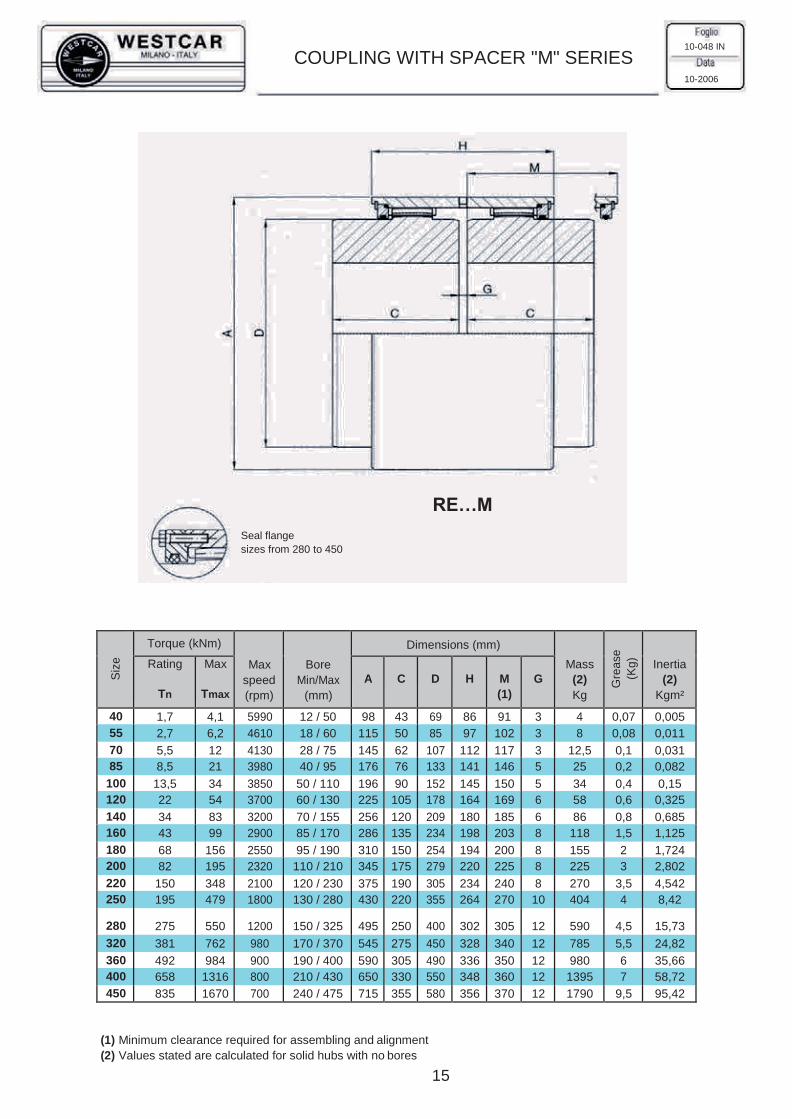
GD
Siz
e
Torque (kNm)
Max
speed
(rpm)
Bore
Min/Max
(mm)
Dimensions (mm)
Mass
(2)
Kg
Gre
ase
(Kg
)
Inertia
(2)
Kgm²
Rating
Tn
Max
Tmax
A
C
D
H
M
(1)
G
40 1,7 4,1 5990 12 / 50 98 43 69 86 91 3 4 0,07 0,005
55 2,7 6,2 4610 18 / 60 115 50 85 97 102 3 8 0,08 0,011
70 5,5 12 4130 28 / 75 145 62 107 112 117 3 12,5 0,1 0,031
85 8,5 21 3980 40 / 95 176 76 133 141 146 5 25 0,2 0,082
100 13,5 34 3850 50 / 110 196 90 152 145 150 5 34 0,4 0,15
120 22 54 3700 60 / 130 225 105 178 164 169 6 58 0,6 0,325
140 34 83 3200 70 / 155 256 120 209 180 185 6 86 0,8 0,685
160 43 99 2900 85 / 170 286 135 234 198 203 8 118 1,5 1,125
180 68 156 2550 95 / 190 310 150 254 194 200 8 155 2 1,724
200 82 195 2320 110 / 210 345 175 279 220 225 8 225 3 2,802
220 150 348 2100 120 / 230 375 190 305 234 240 8 270 3,5 4,542
250 195 479 1800 130 / 280 430 220 355 264 270 10 404 4 8,42
280 275 550 1200 150 / 325 495 250 400 302 305 12 590 4,5 15,73
320 381 762 980 170 / 370 545 275 450 328 340 12 785 5,5 24,82
360 492 984 900 190 / 400 590 305 490 336 350 12 980 6 35,66
400 658 1316 800 210 / 430 650 330 550 348 360 12 1395 7 58,72
450 835 1670 700 240 / 475 715 355 580 356 370 12 1790 9,5 95,42
(1) Minimum clearance required for assembling and alignment
(2) Values stated are calculated for solid hubs with no bores
15
COUPLING WITH SPACER "M" SERIES 10-048 IN
10-2006
RE…M
Seal flange
sizes from 280 to 450

GD
16
(1) Values stated are calculated for standard coupling with maximum bore without key seat
(2) Couplings with hubs suitable for shafts of UNEL-MEC series motors
Couplings of size 125 and 155 are manufactured with 39NiCrMo3 steel, hardened and tempered
Standard hubs
RE…MC
One long hub
RE…MCL
Two long hubs
RE…MCLL
COUPLING WITH SPACER "MC" SERIES 10-049 IN
10-2006
Siz
e
Torque (kNm)
Max
speed
(rpm)
Bore
Min/Max
(mm)
Dimensions (mm) Mass Kg
J
(1)
Kg cm²
Rating
Tn
Max
Tmax
Standard series Long series
Sle
eve
Sta
ndard
hub
Long h
ub
A C D H M G C(2) M(2)
25 600 1524 6000 0 / 28 68 41 42 61 85 3 60 123 0,72 0,48 0,69 8,68
32 1000 2520 5000 0 / 38 85 48,5 55 73 100 3 80 163 1,14 0,99 1,58 25,1
40 1250 3125 4200 0 / 48 95 56 64 82 115 3 80 163 1,68 1,49 2,10 44,82
56 2500 6200 3500 0 / 60 120 68 80 97 140 4 100 204 2,86 2,96 4,22 132,6
63 4000 9260 3000 0 / 70 140 74,5 100 108 153 4 119,5 243 3,75 4,90 7,67 278,2
80 7500 18000 2600 0 / 90 175 82,5 125 125 170 5 140 285 5,58 8,72 14,26 558,6
100 12000 28500 1400 0 / 110 198 105 150 148 216 6 174,5 355 6,63 15,76 25,40 1044,5
125 23600 56250 950 40 / 140 245 140 190 214 288 8 207,5 423 17,70 32,60 49,50 3650
155 40000 90000 700 40 / 175 300 180 240 240 370 10 245 498 28,30 65,50 91,40 9982

GD
17
Siz
e
Torque (kNm)
Max
speed
(rpm)
Bore
Min/Max
(mm)
Dimensions (mm)
Gre
ase
(Kg)
Rating
Tn
Max
Tmax
F
C
D
L
L1
G
S
A
B
K
H
40 1,7 4,1 5990 12 / 50 100 60 69 100 90 3 17 20 12 12 130 0,08
55 2,7 6,2 4610 18 / 60 120 70 85 110 100 3 18 20 12 12 150 0,09
70 5,5 12 4130 28 / 75 152 85 107 140 128 3 29 24 16 16 190 0,15
85 8,5 21 3980 40 / 95 175 95 133 155 143 5 32 24 16 16 210 0,25
100 13,5 34 3850 50 / 110 200 105 152 170 158 5 34 24 16 16 240 0,45
120 22 54 3700 60 / 130 230 120 178 195 179 6 39 32 20 20 270 0,7
140 34 83 3200 70 / 155 260 130 209 205 189 6 45 32 20 20 310 0,9
160 43 99 2900 85 / 170 290 150 234 240 224 8 50 32 20 20 330 1,54
180 68 156 2550 95 / 190 320 175 254 280 264 8 56 32 20 20 360 2,3
200 82 195 2320 110 / 210 350 190 279 300 280 8 62 40 24 22 400 3,2
220 150 348 2100 120 / 230 395 220 305 350 330 8 70 40 24 22 450 3,9
250 195 479 1800 130 / 280 450 250 355 400 375 10 77 50 28 24 510 6,1
280
275
550
1200
150 / 325
545
275
400
430
405
12
80
50
28
24
610
6,5
320 381 762 980 170 / 370 590 300 450 470 440 12 87 60 32 30 660 7,2
360 492 984 900 190 / 400 640 335 490 510 480 12 95 60 32 30 710 8,5
400 658 1316 800 210 / 430 715 360 550 560 520 12 100 80 44 40 810 11,4
450 835 1670 700 240 / 475 780 390 580 600 560 12 110 80 44 40 870 12,5
DISENGAGING COUPLING 10-050 IN
10-2006
STROKE STROKE
RE…DH.MN RE…DH.PM

19
Assembly instruction / Lubrication and maintenance
RE gear couplings are packed and delivered without lubrication. Couplings are supplied with a special corrosion-proof protective grease. You are required to follow the below listed instructions for a correct assembling and maintenance. These instructions generally are applied for a grease lubrication. Special tools are not required for the assembly.
1. Assembly
1.1 check that the minimum space required for assembly is available between the machines as stated on the tables. Verify that the coupling is installed with the hubs in normal or in reversed position.
1.2 disassemble the coupling and clean all the surfaces. 1.3 position the key in the suitable seat on the shaft. Insert the O-ring in the seat of the external sleeve and put it on the
shaft. For sizes starting from 590 insert the O-ring in the closing plate, insert the hub on the shaft paying attention to not damage the O-ring. Do the same with the other half coupling. Use of a molikote based emulsion can be useful for hub assembling.
1.4 for assembly with interference, O-rings or closing plates must be adequately protected during the hub warming up. In case of assembling of a coupling with heat treated toothing, is important that the hub temperature is not higher than 200°C.
1.5 with the hubs assembled on the shafts, check the alignment and the quote “S”, that must comply with the value reported on the dimensional tables with a tolerance of 0.5 mm (axial). Check with care the shafts alignment.
1.6 apply some mastic on the union surfaces on the toothed sleeves of the coupling. For sizes starting from 590 mastic must be applied on contact surfaces of the closing plates. Then insert the bolts and complete the assembly of the coupling. Position the lubrication holes on the toothed sleeves with 90° shifting.
1.7 fill the coupling with the right quantity of grease when the assembly is completed.
1.8 check that the coupling has angular and axial moving. Note: accident prevention rules (d.p.r. 27.04.75 nr. 457 art. 55) require fixed guard on rotating parts.
2. Maintenance
2.1 replace completely the grease every 8000 hours of operation, by carefully cleaning the coupling and checking the shafts alignment.
2.2 for ambient temperature from –10°C to +90°C, use of a grease with EP features and lithium based additive is required. We suggest the use of the following lubricants (with standard ambient and operation conditions):
AGIP: GR-MU/EPO (EP1) SHELL: ALVANIA EP GREASE 1 API: APIGREASE PGX-0 MOBIL: MOBILGREASE-SPECIAL IP: ATHESIA-EPO ESSO: PEN-O-LED-EP 350
2.3 add new grease every 5-6 months if necessary and check the free axial movement of the toothed sleeves.
2.4 in case of grease leakage from the toothed sleeves, disassemble the coupling, clean the union surfaces, apply new mastic and fill the coupling with new grease. For high service temperatures contact our tecnical dept. for the choice of the proper lubricant.
GEAR COUPLING
ASSEMBLY INSTRUCTION
LUBRICATION AND MAINTENANCE
10-051 IN
10-2006

21
Tabella n.2 - Selezione del giunto
Selezione del giunto
La corretta scelta della grandezza del giunto da utilizzare può essere effettuata come segue.
1) A titolo orientativo prestabilire la grandezza del giunto in base al diametro dell’albero su cui
dovrà essere calettato (riferimento tavola dimensionale, fino massimo consentito).
2) Determinare l’effettiva coppia trasmissibile da applicare al giunto, con la seguente formula:
MT max. = P/N x fs x 955 (daNm)
dove: P = Potenza (kW) N = nr. di giri/min
fs = fattore di servizio (vedi tab. 1)
955 = coefficiente fisso
Verificare che la coppia calcolata risulti inferiore od al max. uguale alla coppia nominale del
giunto prestabilito.
3) calcolo del carico radiale sul giunto determinato dal tiro della fune, dal peso del tamburo e
dell’efficienza del paranco.
P = T + G/2 (daN)
dove: P = carico radiale in daN
T = tiro fune in daN
G = forza peso in tamburo in daN
Verificare che il carico radiale calcolato non superi il valore massimo accettabile dal giunto
scelto.
4) Esempio di selezione:
Diametro albero riduttore 220 mm
Potenza da trasmettere 45 kW
Numero di giri 9
Tiro fune 10.000 daN
Massa tamburo 1250 daN
Fattore di servizio 2 (vedi tabella 1)
Calcolo della coppia MT max. = 45/9x2x955 = 9550 daNm
Calcolo del carico radiale P = 10.000+1300/2 = 10.650 daN
Verificando i valori ottenuti con i valori indicati nella tabella n. 2 risulta che il giunto idoneo
all’applicazione richiesta è il tipo AR 450/J.
GIUNTI PER TAMBURO PORTAFUNI
SELEZIONE DEL GIUNTO
Coupling selection
The correct selection of the coupling to use can be use can be done according to the following procedure:
1) Pre-select the coupling size according to the shaft diameter of the gear box to which the coupling hub has
to be mounted (reference dimensional table, hole maximum allowed )
2) Determine your real transmissible torque to apply to the coupling with the following formula :
MT MAX. = P/N x fs x 955 (daNm )
Where: P = power kW
N = r.p.m. of drum
sf = service factor (see table n° 1)
955 =fixed coefficient
Check that the applied torque doesn't exceed the nominal torque for the pre-selected coupling.
3) calculate the radial load on the coupling, function of the rope pull load, the hoisting efficiency and rope
drum weight, use the following formula:
P = T + G/2 (daN)
P = radial load (daN)
T = rope pull load
G = drum force weight (daN)
Check that the calculated radial load doesn't exceed the maximum acceptable radial load for the pre-
selected coupling.
4) Example:
Gearbox shaft diameter 220mm.
Power to transmit 45kW
r.p.m. 9
Rope pull load 10.000 daN
Drum force weight 1.250 daN
Service factor 2
Torque calculated MT max. = 45/9x2x955 = 9550daN
Checking the values obtained with the values indicated in the table n° 2 it results that the right coupling for
that application is the type AR 450/J
Tabella n.1 - Fattore di servizio “fs” secondo normative standard
Secondo normativa DIN 15020 IBm Iam 2m 3m 4m 5m
Secondo normativa FEM T0 T1 T2 T3 T4 T5 T6 T7 T8 T9
Fattore di servizio 1.12 1.25 1.4 1.6 1.8 2 2.25 2.5 2.75 3
GIUNTO AR…/J 140 160 180 200 220 240 260 280 310 340 400 420 450 530 560 600 670 730
Foro d
in mm
sgrossato 30 30 30 50 50 60 60 60 70 70 90 90 100 100 120 120 140 140
massimo 65 80 85 95 105 115 130 140 160 175 210 220 235 290 310 330 375 410
Massa kg 10 12 20 24 28 32 40 55 72 94 130 160 200 300 370 415 600 700
Coppia nom. daNm 250 400 780 1350 1600 1850 2200 3200 4000 5100 7700 9200 13000 19000 31000 42000 54000 75000
Carico radiale daN 1200 1400 1800 2500 3100 3700 4200 5200 6300 7950 11250 12300 14500 20200 22200 26000 32300 39000
Tabella n.2 - Selezione del giunto
MILANO - ITALY
MILANO
ITALY
Foglio
30-054 IT
Data
10-2006
T

22
GIUNTI PER TAMBURO PORTAFUNI
DIMENSIONI
GIUNTO AR…/J 140 160 180 200 220 240 260 280 310 340 400 420 450 530 560 600 670 730
Foro d
in mm
sgrossato 30 30 30 50 50 60 60 60 70 70 90 90 100 100 120 120 140 140
massimo 65 80 85 95 105 115 130 140 160 175 210 220 235 290 310 330 375 410
Dimens.
in mm
D 230 250 280 320 340 360 380 400 420 450 510 550 580 650 680 710 780 850
M 90 110 120 135 145 163 183 195 225 255 310 325 350 425 455 490 555 615
F h6 140 160 180 200 220 240 260 280 310 340 400 420 450 530 560 600 670 730
T 42 42 42 45 45 45 45 45 45 60 60 60 60 65 65 81 81 81
L 90 95 100 110 125 130 145 170 175 185 220 240 260 315 350 380 410 450
H 12 12 12 15 15 15 15 15 15 20 20 20 20 25 25 25 25 25
N 200 220 250 280 300 320 340 360 380 400 460 500 530 600 630 660 730 800
G 110 130 142 157 175 195 215 231 261 286 346 361 386 461 491 526 591 651
Ø E H8 14 14 14 18 18 18 18 18 18 24 24 24 24 24 24 28 28 28
N° fori 6 6 6 6 6 6 6 6 6 6 6 6 8 8 24 24 24 24
K h9 200 220 250 280 300 320 340 360 380 400 460 500 530 580 600 640 700 760
Massa Kg 13 16 24 29 35 42 54 67 90 108 150 190 230 395 460 520 740 890
Coppia nom. max 250 400 780 1350 1600 1850 2200 3200 4000 5100 7700 9200 13000 19000 31000 42000 54000 75000
Carico radiale 1200 1400 1800 2500 3100 3700 4200 5200 6300 7950 11250 12300 14500 20200 25000 30000 34000 39000
Fori di estrazione
Nota:
La quota "L" indicata si riferisce alla dimensione standard.
Su richiesta, è possibile fornire mozzi con differenti lunghezze.
Campana
Argano
Mozzo
Riduttore
Carico
lubrificante
MILANO - ITALY
MILANO
ITALY
Foglio
30-055 IT
Data
10-2006
T
Giu
nti
pe
r ta
mb
uri
po
r

23
GIUNTI PER TAMBURO PORTAFUNI
ISTRUZIONI DI MONTAGGIO
Schema di montaggio
I giunti AR…/J vengono forniti senza lubrificante.
Esternamente dispongono di un protettivo resistente
all corrosione. Non occorrono attrezzature speciali e
nemmeno necessita rimuovere i rulli bombati dalle
sedi. Il calettamento del mozzo sull’albero deve es-
sere effettuato con una leggera interferenza.
Procedere come segue:
1) Togliere le guarnizioni toroidali dal mozzo.
2) Riscaldare il mozzo in bagno d’olio, oppure con
fiamma in modo uniforme a temperatura di cir-
ca 120°C, avendo cura di non superare 130 -
135°C.
3) Calettare il mozzo dopo aver controllato il mon-
taggio della linguetta, che non deve presentare
spigoli vivi; la larghezza e l’altezza devono esse-
re compatibili con le dimensioni della cava pre-
sente sul mozzo.
Disassamento
Manutenzione
1) Ogni 6000 ore di funzionamento sosti-
tuire il grasso lubrificante ed effettua-
re una radicale pulizia e controllare lo
stato di usura delle sedi dei rulli.
2) Utilizzare grasso con caratteristiche
EP ed additivi al litio, per temperature
ambienti comprese tra -10°C e 90°C.
Elenchiamo a titolo informativo i seguenti
lubrificanti da noi consigliati:
AGIP GR-MU/EPO (EP1)
IP ATHESIA EPO
MOBILGREASE SPECIAL
ESSO PEN-O-LED EP 360
SHELL ALVANIA EP GREASE I
API GREASE PGX-O
3) Ogni sei mesi circa aggiungere, se oc-
corre, nuovo grasso lubrificante.
MILANO - ITALY
MILANO
ITALY
Foglio
30-056 IT
Data
10-2006
Giunto a rulli
Argano
Riduttore
T

s.r.l.
MILANO
ITALY
WESTCAR s.r.l. Via Monte Rosa, 14 - 20149 MILANO (Italy) Tel. +39 02.76.11.03.19 r.a. - Fax +39 02.76.11.00.41 E-mail: [email protected] - www.westcar.it
Australia
Great Britain
Romania
Austria
Holland
Singapore
Belgium
Hungary
Slovenja
Canada
India
South Africa
Ceka Republik
Indonesia
Spain
China - Shanghai
Iran
Sweden
Cyprus
Israel
Switzerland
Denmark
Korea
Taiwan
Egypt
Malaysia
Thailand
Finland
New Zealand
Turkey
France
Norway
U.S.A.
Germany
Portugal
WESTCAR WORLD WIDE
Distributor