gear units reductores de velocidad riduttori ad · pdf filereductores de velocidad riduttori...
TRANSCRIPT

Gear Units Reductores de velocidadRiduttori ad ingranaggi Fast Track
Catalog MD 20.12 · 2010
FLENDER gear units
www.siemens.com/drivetechnology
Subject to change without prior notice Order No.: E86060-K5720-A221-A1-7R00Dispo 18407KG 0810 2.0 Ro 18 En/Es/ItPrinted in Germany© Siemens AG 2010
Siemens AGIndustry SectorDrive Technologies DivisionMechanical DrivesPostfach 136446393 BOCHOLTGERMANY
The information provided in this catalog contains descriptions or characteristics of performance which in case of actual use do not always apply as described or which may change as a result of further development of the products. An obligation to provide the respective characteristics shall only exist if expressly agreed in the terms of contract. Availability and technical specifications are subject to change without notice.All product designations may be trademarks or product names of Siemens AG or supplier companies whose use by third parties for their own purposes could violate the rights of the owners.
Este catálogo contiene descripciones o prestaciones que en el caso de aplicación concreta pueden no coincidir exactamente con lo descrito, o bien haber sido modificadas como consecuencia de un ulterior desarrollo del producto. Por ello, la presencia de las prestaciones deseadas sólo será vinculante si se ha estipulado expresamente al concluir el contrato. Reservada la posibilidad de suministro y modificaciones técnicas.Todos los nombres de productos pueden ser marcas registradas o nombres protegidos de Siemens AG u otras empresas proveedoras suyas cuyo uso por terceros para sus fines puede violar los derechos de sus titulares.
Le informazioni riportate in questo catalogo contengono descrizioni o caratteristiche che potrebbero variare con l’evolversi dei prodotti o non essere sempre appropriate, nella forma descritta, per il caso applicativo concreto. Le caratteristiche richieste saranno da considerare impegnative solo se espressamente concordate in fase di definizione del contratto. Con riserva di disponibilità di fornitura e modifiche tecniche.Tutte le denominazioni dei prodotti possono essere marchi oppure denominazioni di prodotti della Siemens AG o di altre ditte fornitrici, il cui utilizzo da parte di terzi per propri scopi può violare il diritto dei proprietari.
Answers for industry.
AUD_MD_20.12_umschlag_A4_ES_EN_IT.indd 1 11.08.10 10:08


General InformationIndicaciones generalesAvvertenze generali
Guidelines for the SelectionGuía para la selecciónNorme per il dimensionamento
Type H2.HTipo H2.HTipo H2.H
Type H3.HTipo H3.HTipo H3.H
Type H4.HTipo H4.HTipo H4.H
Type B3.HTipo B3.HTipo B3.H
Type B4.HTipo B4.HTipo B4.H
Data SheetHoja de datosFoglio dati
2
3
4
6
8
10
12
15
FLENDER gear units
Gear Units Reductores de velocidadRiduttori ad ingranaggi
Fast Track
Catalog MD 20.12 • 2010
AUD_MD_20.12_inhalt_A4_ES_EN_IT.indd 1 11.08.10 10:06

1/2 Siemens MD 20.12 · 2010
Answers for Industry.
Siemens Industry answers the challenges in the manufacturing
and the process industry as well as in the building automation
business. Our drive and automation solutions based on Totally
Integrated Automation (TIA) and Totally Integrated Power (TIP)
are employed in all kinds of industry. In the manufacturing and the
process industry. In industrial as well as in functional buildings.
Siemens offers automation, drive, and low-voltage switching technology as well as industrial software from standard products up to entire industry solutions. The industry software enables our industry customers to optimize the entire value chain – from product design and develop-ment through manufacture and sales up to after-sales service. Our electrical and mechanical components offer integrated technologies for the entire drive train – from couplings to gear units, from motors
to control and drive solutions for all engineering industries. Our technology platform TIP offers robust solutions for power distribution.
Check out the opportunities our automation and drive solutions provide. And discover how you can sustainably enhance your competitive edge with us.
AUD_MD_20.12_inhalt_A4_ES_EN_IT.indd 2 11.08.10 10:07

Answers for Industry.
Siemens Industry tiene la respuesta a los desafíos en la automati-
zación manufacturera, de procesos y de edificios. En efecto, nuestras
soluciones de accionamiento y automatización, basadas en Totally
Integrated Automation (TIA) y Totally Integrated Power (TIP), se
utilizan en todos los sectores. Tanto en la industria manufacturera
como en la industria de procesos. Al igual que en edificios
industriales y terciarios.
Answers for Industry.
Siemens Industry fornisce risposte alle sfide nel campo dell‘automa-
zione manifatturiera e di processo nonché della Building Automation.
Le nostre soluzioni di azionamento e automazione basate su Totally
Integrated Automation (TIA) e Totally Integrated Power (TIP) trovano
applicazione in tutti i settori. Nell‘industria manifatturiera
e nell‘industria di processo. E altrettanto negli edifici funzionali.
En nuestra gama encontrará todo lo que busca para automatización, accionamientos y aparatos de baja tensión, así como soft-ware industrial, y desde productos estándar hasta soluciones sectoriales complejas. Nuestro software industrial permite a nuestros clientes del sector productivo optimizar su completa cadena de valor añadido, desde el diseño y el desarrollo del producto, pasando por la fabricación y venta, hasta el servicio técnico. Nuestros componentes eléctricos y mecánicos le per-miten disfrutar de tecnologías integradas para la completa cadena cinemática, desde
el acoplamiento hasta el reductor, desde el motor hasta soluciones de control y accionamientos para todos los sectores de la construcción de maquinaria. Con la plataforma tecnológica TIP le ofrecemos soluciones homogéneas e integradas para la distribución eléctrica.
Cerciórese por sí mismo de las posibilidades que le ofrecen nuestras soluciones de auto-matización y accionamiento. Y descubra cómo podemos a ayudarle a aumentar de forma sostenida su competitividad.
Potete trovare presso di noi tutto quanto concerne la tecnica di automazione, di azionamento e la tecnica di manovra a bas-sa tensione nonché software industriale, dai prodotti standard fino a soluzioni com-plete specifiche per settori. Con il software industriale i nostri clienti ottimizzano, a partire dalla piccola impresa produttiva, il loro intero processo di creazione del valore aggiunto – dal design e dallo sviluppo del prodotto, attraverso la produzione e la commercializzazione fino al service. Con i nostri componenti elettrici e meccanici, noi
vi offriamo tecnologie integrate per l‘intera linea di azionamento – dal giunto di accop-piamento fino al riduttore, dal motore fino alle soluzioni di comando e azionamento per tutti i tipi di macchine. Con la piatta-forma tecnologica TIP vi offriamo soluzioni omogenee per la distribuzione dell‘energia. Convincetevi voi stessi delle possibilità che vi offrono le nostre soluzioni di automazione e azionamento. E scoprite come poter aumen- tare con noi in modo duraturo la vostra competitività.
1/3Siemens MD 20.12 · 2010
AUD_MD_20.12_inhalt_A4_ES_EN_IT.indd 3 11.08.10 10:07
2 Siemens MD 20.12 · 2010
Gear Units
General InformationThe FLENDER gear unit series is a uni-versal standard gear unit range developedfor the use in nearly all fields of mechani-cal power transmission technology. Sincethe launching on the market, the gearunits have proved their value in more than80,000 drives where they are operatingreliably.
With Fast Track , Siemens now offers aspecial selection from its extensive gearunit range (for more types and sizes pleaserefer to the main brochure MD 20.1; infor-mation about subranges on request).Ordering quantities of up to 3 Fast Trackgear units per type according to this bro-chure are available ex works, as a rule
within 14 days
from the date of the acknowledgement ofthe order.
Details required in orders:� Type and size; design� Transmission ratio� Seals� Add-on pieces� Language and quantity required of documentation
(operating instructions, dimensioned drawings,spare parts lists and spare parts drawings) andlanguage for the name plates.
The following items are absolutely to be ob-served!� For other designs and dimensions please refer
to the main brochure MD 20.1.� For permissible radial forces, see main brochure
MD 20.1.� Gear units available with dip lubrication only.
� Gear units are protected against corrosion for24 months.
� Inspection: test report 2.2.� Illustrations are examples only and are not strictly
binding.Dimensions are subject to change.
� The weights are mean values and not strictly bind-ing.
� To prevent accidents, all rotating parts shouldbe guarded according to local and nationalsafety regulations.
� Prior to commissioning, the operating instructionsmust be observed.The gear units are delivered ready for operationbut without oil filling.
� Oil quantities given are guide values only.The exact quantity of oil depends on the markson the oil dipstick.
� The oil viscosity has to correspond to the datagiven on the name plate.
� Permitted lubricants may be used only. You willfind current operating instructions and lubricantselection tables at:www.siemens.com/gearunits
Reductores de velocidad
Indicaciones generalesLa serie actual de reductores de velocidadFLENDER comprende un programa estan-darizado universal, desarrollado para serempleado en casi todos los sectores deaccionamientos mecánicos. Desde su im-plantación en el mercado, más de 80.000accionamientos han sido equipados satis-factoriamente con estos reductores, cum-pliendo con gran fiabilidad sus exigencias.Con Fast Track Siemens les ofrece unaselección especial de su amplio programade reductores. (para otros tipos y tamaños,ver el catálogo principal MD 20.1; consúl-tenos para información sobre otros progra-mas).La disponibilidad, de los reductores reco-gidos en este catálogo Fast Track paracantidades de hasta 3 unidades por tipo,puestos en nuestra fca. de Alemania con
14 días de plazo
a partir de la confirmación de pedido.
Datos necesarios para realizar un pedido:� Ejecución y tamaño� Índice de reducción� Tipo de retenes� Accesorios� Cantidad e idioma de la documentación (instruccio-
nes, hoja de medidas, lista de repuestos y plano dedespiece) e idioma de las placas en el reductor.
Los siguientes puntos han de ser observadosnecesariamente!� Para otras ejecuciones y dimensiones, ver catá-
logo principal MD 20.1.� Para esfuerzos radiales, ver catálogo principal
MD 20.1.� Reductores solamente disponibles para lubrica-
ción por barboteo.� Reductores con conservación para 24 meses.� Recepción: Certificado de taller 2.2.� Las representaciones son a título indicativo, no
vinculantes.Reservado el derecho a modificar medidas.
� Los pesos indicados son valores medios, no vin-culantes.
� El comprador ha de proteger todas las partesrotantes contra un contacto accidental, cump-liendo la legislación local vigente.
� Antes de la puesta en marcha se han de obser-var las instrucciones de servicio.Los reductores son suministrados listos para fun-cionar, pero sin relleno de aceite.
� Las cantidades de aceite indicadas son a títuloindicativo, no vinculantes. La cantidad de aceiteexacta se refleja en la marca de la barra de nivelde aceite.
� La viscosidad del aceite ha de corresponder a loindicado en la placa de características.
� Solamente se autorizan los aceites homologa-dos. Los manuales de instrucción y tablas de lubri-cantes en vigor se encuentran en internet, bajo:www.siemens.com/gearunits
Riduttori ad ingranaggi
Avvertenze generaliLa serie di riduttori ad ingranaggi FLENDERè una gamma di riduttori standard pro-gettata per l’impiego in quasi tutti i campidella trasmissione meccanica. Dall’intro-duzione sul mercato di questo prodotto, iriduttori si sono affermati in oltre 80.000applicazioni ed assicurano il loro servizioin modo affidabile.
Con Fast Track Siemens ora offre unaselezione speciale del suo esaustivoprogramma di riduttori ad ingranaggi (peraltri tipi e grandezze v. catalogo principaleMD 20.1; informazioni su programmi deri-vati a richiesta).I riduttori Fast Track riportati in questocatalogo sono disponibili dalla fabbricafino a 3 pezzi per tipo con
consegna 14 giorni
dalla data di conferma ordine.
Dati necessari per l’ordine:� Tipo e grandezza, esecuzione� Rapporto di riduzione� Guarnizioni� Parti applicate� Quantità e lingua della documentazione (manuale
d’uso e manutenzione, disegno d’ingombro listaricambi e disegno in sezione), lingua delle terg-hette dei riduttori.
Rispettare assolutamente i seguenti punti!
� Esecuzioni e dimensioni differenti: vedi catalogoprincipale MD 20.1.
� Forze radiali ammissibili: v. catalogo principaleMD 20.1.
� Riduttori disponibili solo con lubrificazione a immer-sione.
� I riduttori sono protetti contro la corrosione per24 mesi.
� Collaudo: certificato 2.2.� Le illustrazioni sono solo esempi e non sono
impegnative.Ci riserviamo modifiche dimensionali.
� I pesi indicati sono valori medi non impegnativi.� L’acquirente deve proteggere le parti in movimento
dai contatti involontari. Si devono osservare le mi-sure di sicurezza in vigore nel paese di installa-zione.
� Prima della messa in funzione, esaminare il manu-ale d’uso e manutenzione.I riduttori sono forniti pronti per il funzionamento, masenza riempimento d’olio.
� I dati sulle quantità d’olio sono valori indicativisenza impegno. E’determinante la tacca di livelloolio sull’astina di livello.
� La viscosità dell’olio deve corrispondere ai datiindicati in targhetta.
� Si devono utilizzare solo lubrificanti ammessi.Trovate i manuali d’uso e manutenzione attuali e letabelle dei lubrificanti su:www.siemens.com/gearunits
Viscosity ISO-VG at 40 C in mm 2/s (cSt)Viscosidad ISO-VG a 40 C en mm 2/s (cSt)
Viscosità ISO-VG o 40 C in mm 2/s (cSt)
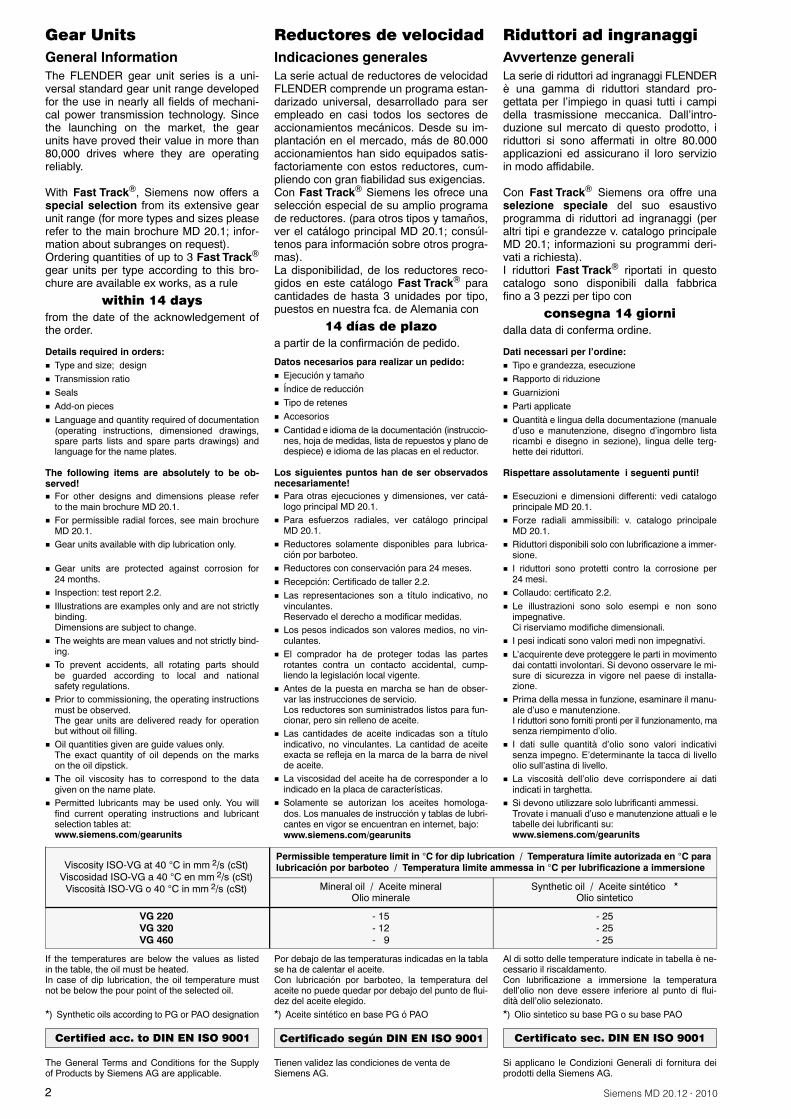
Permissible temperature limit in C for dip lubrication / Temperatura límite autorizada en C paralubricación por barboteo / Temperatura limite ammessa in C per lubrificazione a immersione
Mineral oil / Aceite mineralOlio minerale
Synthetic oil / Aceite sintético �Olio sintetico
VG 220VG 320VG 460
- 15- 12- 9
- 25- 25- 25
If the temperatures are below the values as listedin the table, the oil must be heated.In case of dip lubrication, the oil temperature mustnot be below the pour point of the selected oil.
�) Synthetic oils according to PG or PAO designation
Certified acc. to DIN EN ISO 9001
The General Terms and Conditions for the Supplyof Products by Siemens AG are applicable.
Por debajo de las temperaturas indicadas en la tablase ha de calentar el aceite.Con lubricación por barboteo, la temperatura delaceite no puede quedar por debajo del punto de flui-dez del aceite elegido.�) Aceite sintético en base PG ó PAO
Certificado según DIN EN ISO 9001
Tienen validez las condiciones de venta deSiemens AG.
Al di sotto delle temperature indicate in tabella è ne-cessario il riscaldamento.Con lubrificazione a immersione la temperaturadell’olio non deve essere inferiore al punto di flui-dità dell’olio selezionato.�) Olio sintetico su base PG o su base PAO
Certificato sec. DIN EN ISO 9001
Si applicano le Condizioni Generali di fornitura deiprodotti della Siemens AG.

3Siemens MD 20.12 · 2010
Gear Units
Guidelines for the SelectionThe calculation example below applies to:
� Constant power rating at n1 = 1500 min-1
� Drive via electric motor with n = 1500 min-1
� Max. 5 starts per hour with uniform directionof load
� Continuous operation 24h/day� Installation in large halls, workshops
(wind velocity w 1,4 m/s)� Altitude: up to 1000 mFor other operating conditions please refer to themain brochure MD 20.1.
Reductores de velocidad
Guía para la selecciónLa siguiente selección (ver ejemplo) parte de:
� Par constante a n1 = 1500 min-1
� Motor eléctrico con n = 1500 min-1
� Máx. 5 arranques por hora en el mismo sentidode carga
� Servicio continuo 24h/día� Colocación en sala grande, nave
(velocidad del viento w 1,4 m/s)� Altitud: hasta 1000 mPara otras condiciones de servicio: ver catálogoprincipal, MD 20.1.
Riduttori ad ingranaggi
Norme per il dimensionamentoIl seguente esempio di dimensionamento siapplica per:� Potenza costante a n1 = 1500 min-1
� Comando mediante motore elettr. a n = 1500 min-1
� Max. 5 avviamenti/ora con uguale direzionedel carico
� Servizio continuo 24h/giorno� Installazione in ambienti grandi (velocità del
vento w 1,4 m/s)� Altezza: fino a 1000 mPer altre condizioni d’impiego: v. catalogo princi-pale MD 20.1.
Service factors Factores de servicio Fattori di servizio
Thermal factor / Factor térmico / Coeff. termico f4
Ambienttemperature
Temperatura deambiente
Temperaturaambiente
10 C20 C30 C40 C50 C
Operating cycle per hour (ED) in %Duración de la utilización por
hora (ED) en %Durata d’inserzione/ora (ED) in %
1.111.000.880.750.63
1.311.181.040.890.74
1.601.441.271.080.91
2.141.931.701.451.22
3.643.282.892.462.07
100 80 60 40 20
uniformconstanteuniforme
Belt conveyors 150 kW; centrifugal pumps; centrifugesTransportador de cinta 150 kW; bombas centrífugas; centrífugasTrasportatori a nastro 150 kW; pompe centrifughe; centrifughe
Load classification of driven machineFactor de carga para la máquina a accionarParametro di carico della macchina operatrice
1.3
moderateshockmediamedio
f1
Belt conveyors > 150 kW; mixers; apron conveyors; agitators;water screw pumpsTransportador de cinta > 150 kW; mezcladora; cinta de placas;agitadores; rosca transportadora de aguaTrasportatori a nastro > 150 kW; mescolatori; trasp. a piastre;agitatori; pompe a coclea
1.6
heavy shockpesadapesante
Roller drives (rolling mills); breakersAccionamientos de rodillos (laminadora); trituradoras de rodillosComandi per cilindri (laminatoio); frantoi
2
Example:Known criteria:PRIME MOVERElectric motor: P1 = 75 kWMotor speed: n1 = 1500 min-1
DRIVEN MACHINEBelt conveyor: P2 = 66 kWSpeed: n2 = 26 min-1
Duty: 12h/dayOperating cycleper hour: ED = 100Ambient temperature: 30 CInstallation in a hall: (w 1,4 m/s)Altitude: sea level
GEAR UNIT DESIGNBevel-helical gear unitMounting position: horizontalOutput shaft d2: on RH side, design CDirection of rotationof output shaft d2: ccw
Required:Type and size of gear unit
1. Selection of gear unit type and size
Ejemplo:Datos:MÁQUINA MOTRIZMotor eléctrico: P1 = 75 kWVelocidad motor: n1 = 1500 min-1
MÁQUINA ACCIONADATransportador de banda: P2 = 66 kWVelocidad: n2 = 26 min-1
Servicio diario: 12h/diaDuración de la utilizaciónpor hora: ED = 100Temperatura ambiente: 30 CColocación en una nave: (w 1,4 m/s)Altitud: nivel del mar
EJECUCIÓN DEL REDUCTORReductor de engranajes cónico-helicoidalesPosición de montaje: horizontalEje de salida d2: lado derecho, ejecución CSentido de girodel eje de salida: a izquierdas
Se busca:Tipo y tamaño de reductor
1. Determinación del tipo y tamaño delreductor
Esempio:Dati:MACCHINA MOTRICEMotore elettr.: P1 = 75 kWVelocità motore: n1 = 1500 min-1
MACCHINA OPERATRICENastro trasportatore: P2 = 66 kWVelocità: n2 = 26 min-1
Durata d’esercizio: 12h/giornoDurata d’inserzioneper ora: ED = 100Temperatura ambiente: 30 CInstallazione al coperto: (w 1,4 m/s)Altezza: livello del mare
ESECUZIONE RIDUTTORERiduttore a ingranaggi conico-cilindriciMontaggio: orizzontaleAlbero lento d2: destra, esecuzione CSenso di rotazionealbero lento d2: sinistra
Richiesti:Tipo e grandezza riduttore
1. Determinazione di tipo e grandezza delriduttore
is =n1n2
= 150026
= 57.7 iN = 561.1 Calculation of transmission ratio iN
Determinación del índice de reducción iNDeterminazione rapp. di rid. iN
PN P2 x f1 = 66 x 1.3 = 85.8 kW1.2 Determination of the gear unit nominal power rating PN
Determinación de la potencia nominal del reductor PNDeterminazione potenza nominale PN
Selected from power rating table: type B3, gearunit size 9, with PN = 100 kW
2. Determination of thermal capacity PG
De la tabla de potencias se selecciona: Tipo B3,tamaño 9, con PN = 100 kW
2. Determinación de la capacidad térmicalímite PG
Scelto da tabella di potenza tipo B3, grandezza 9con PN = 100 kW
2. Determinazione capacità termica limitePG
PG = PGA x f4 = 64.8 x 0.88 = 57 kWPG = 57 kW < P2 = 66 kW
2.1 Thermal capacity without auxiliary cooling PGA acc. to table for type B3Capacidad térmica sin refrigeración adicional, ver PGA en tabla del tipo B3Capacità termica limite senza raffr. ausil. PGA da tabella tipo B3
A gear unit without auxiliary cooling is notsufficient!
El reductor necesita refrigeración adicional! Riduttore senza raffreddamento ausiliarionon è adatto!
PG = PGB x f4 = 140.3 x 0.88 = 123.4 kWPG = 123.4 kW > P2 = 66 kW
2.2 Thermal capacity with fan cooling PGB acc. to table for type B3Capacidad térmica con ventilador, ver PGB en tabla del tipo B3Capacità termica limite con ventola PGB da tabella tipo B3
A gear unit with fan is sufficient! Reductor con ventilador válido! Riduttore con ventola è adatto!
4 Siemens MD 20.12 · 2010
Gear Units Reductores de velocidad Riduttori ad ingranaggi
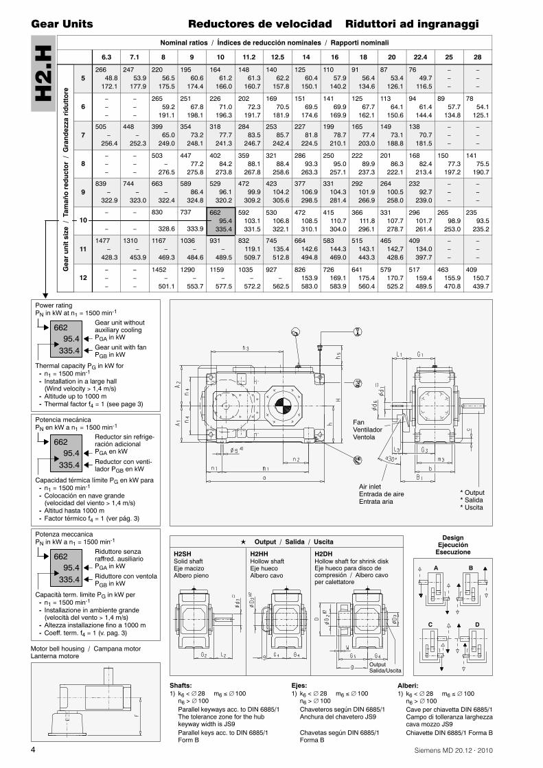
Nominal ratios / Índices de reducción nominales / Rapporti nominali
6.3 7.1 8 9 10 11.2 12.5 14 16 18 20 22.4 25 28G
ear
un
itsi
ze/
Tam
año
red
uct
or
/G
ran
dez
zari
du
tto
re
5266
48.8172.1
24753.9
177.9
22056.5
175.5
19560.6
174.4
16461.2
166.0
14861.3
160.7
14062.2
157.8
12560.4
150.1
11057.9
140.2
9156.4
134.6
8753.4
126.1
7649.7
116.5
6265
59.2191.1
25167.8
198.1
22671.0
196.3
20272.3
191.7
16970.5
181.9
15169.5
174.6
14169.9
169.9
12567.7
162.1
11364.1
150.6
9461.4
144.4
8957.7
134.8
7854.1
125.1
7505
256.4
448
252.3
39965.0
249.0
35473.2
248.1
31877.7
241.3
28483.5
246.7
25385.7
242.4
22781.8
224.5
19978.7
210.1
16577.4
203.0
14973.1
188.8
13870.7
181.5
8503
276.5
44777.2
275.8
40284.2
273.8
35988.1
267.8
32188.4
258.6
28693.3
263.3
25095.0
257.1
22289.9
237.3
20186.3
222.1
16882.4
213.4
15077.3
197.2
14175.5
190.7
9839
322.9
744
323.0
663
322.4
58986.4
324.8
52996.1
320.2
47299.9
309.2
423104.2305.6
377106.9298.5
331104.3281.4
292101.9266.9
264100.5258.0
23292.7
239.0
10830
328.6
737
333.9
66295.4
335.4
592103.1331.5
530106.8322.1
472108.5310.1
415110.7304.0
366111.8296.1
331107.7278.7
296101.7261.4
26598.9
253.0
23593.5
235.2
111477
428.3
1310
453.9
1167
469.3
1036
484.6
931
489.5
832119.1509.7
745135.4512.8
664142.6494.8
583144.3469.0
515143.1443.3
465142,7428.6
409134.0397.7
121452
501.1
1290
553.7
1159
577.5
1035
572.2
927
562.5
826153.9583.0
726169.1583.9
641175.4560.4
579170.7525.2
517159.4489.5
463155.9470.8
409150.7439.7
H2
.H
FanVentiladorVentola
Air inletEntrada de aireEntrata aria
� Output� Salida� Uscita
Thermal capacity PG in kW for- n1 = 1500 min-1
- Installation in a large hall(Wind velocity 1,4 m/s)
- Altitude up to 1000 m- Thermal factor f4 = 1 (see page 3)
66295.4
Power ratingPN in kW at n1 = 1500 min-1
Gear unit withoutauxiliary coolingPGA in kW
Gear unit with fanPGB in kW
DesignEjecución
Esecuzione
335.4
Capacidad térmica límite PG en kW para- n1 = 1500 min-1
- Colocación en nave grande(velocidad del viento 1,4 m/s)
- Altitud hasta 1000 m- Factor térmico f4 = 1 (ver pág. 3)
66295.4
Potencia mecánicaPN en kW a n1 = 1500 min-1
Reductor sin refrige-ración adicionalPGA en kW
Reductor con venti-lador PGB en kW335.4
Capacità term. limite PG in kW per- n1 = 1500 min-1
- Installazione in ambiente grande(velocità del vento 1,4 m/s)
- Altezza installazione fino a 1000 m- Coeff. term. f4 = 1 (v. pag. 3)
66295.4
Potenza meccanicaPN in kW a n1 = 1500 min-1
Riduttore senzaraffred. ausiliarioPGA in kW
Riduttore con ventolaPGB in kW335.4
Motor bell housing / Campana motorLanterna motore
A B
C D
H2SHSolid shaftEje macizoAlbero pieno
H2HHHollow shaftEje huecoAlbero cavo
H2DHHollow shaft for shrink diskEje hueco para disco decompresión / Albero cavoper calettatore
� Output / Salida / Uscita
OutputSalida/Uscita
Ejes:1) k6 < 28 m6 100
n6 > 100Chaveteros según DIN 6885/1Anchura del chavetero JS9
Chavetas según DIN 6885/1Forma B
Shafts:1) k6 < 28 m6 100
n6 > 100Parallel keyways acc. to DIN 6885/1The tolerance zone for the hubkeyway width is JS9Parallel keys acc. to DIN 6885/1Form B
Alberi:1) k6 < 28 m6 100
n6 > 100Cave per chiavetta DIN 6885/1Campo di tolleranza larghezzacava mozzo JS9Chiavette DIN 6885/1 Forma B

5Siemens MD 20.12 · 2010
Gear Units Reductores de velocidad Riduttori ad ingranaggi
SizeTamañoGrand.
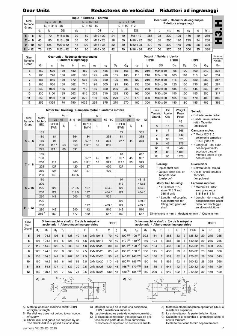
Input / Entrada / EntrataGear unit / Reductor de engranajes
Riduttore a ingranaggiiN = 6.3 - 11.2 iN = 12.5 - 22.4iN = 8 - 14 iN = 16 - 28
d1 l1 l3 DS d1 l1 l3 DS A1 A2 b B1 c d6 m3 n1 n4 s h -1
5 + 6 50 100 80 M16 x 36 38 80 60 M12 x 28 225 260 255 230 28 150 220 105 180 19 230
7 + 8 60 135 105 M20 x 42 50 110 80 M16 x 36 272 305 300 255 35 200 260 120 215 24 280
9 + 10 75 140 110 M20 x 42 60 140 110 M20 x 42 312 355 370 285 40 200 320 145 245 28 320
11 + 12 90 165 130 M42 x 50 70 140 105 M20 x 42 372 420 430 325 50 210 370 165 300 35 380
SizeTamañoGrand.
Gear unit / Reductor de engranajesRiduttore a ingranaggi
Output / Salida / UscitaH2SH H2HH H2DH
G1 G3 a h5 H m1 n2 n3 G2 G4 d2 l2 DS D2 D2 D3 G5
5 195 215 640 150 482 430 100 405 165 165 100 210 M24 x 50 95 100 100 240
6 195 215 720 150 482 510 145 440 165 165 110 210 M24 x 50 105 110 110 240
7 210 240 785 190 572 545 130 500 195 195 120 210 M24 x 50 115 120 120 280
8 210 240 890 190 582 650 190 545 195 195 130 250 M24 x 50 125 130 130 285
9 240 270 925 205 662 635 155 585 235 235 140 250 M30 x 60 135 140 145 330
10 240 270 1025 215 662 735 205 635 235 235 160 300 M30 x 60 150 150 155 350
11 275 310 1105 250 782 775 180 710 270 270 170 300 M30 x 60 165 165 170 400
12 275 310 1260 250 790 930 265 780 270 270 180 300 M30 x 60 180 180 185 405
Motor bell housing / Campana motor / Lanterna motore
SizeTamañoGrand.
MotorMotore
IEC
iN =
BIPEXBWN
12.5 - 22.4 16 - 28f
5 + 6200 3) 112 402
225 3) 127 443
7 + 8
225 4) 127 473.5
250 4) 127 475
280 4) 142 494
9 + 10 280 142 530
11 + 12 315 � 162 606
SizeTam.
Grand.
Driven machine shaft / Eje de la máquinaaccionada / Albero macchina operatrice H2HH Driven machine shaft / Eje de la máquina
accionada / Albero macchina operatrice H2DH
d2 d4 d5 f1 l l1 r s m g d2 d3 d4 d5 f1 l l1 r HSD W D g
5 95 94.5 105 5 328 40 1.6 2xM10x18 70 40 100 g6 100 h6 99.5 114 5 383 53 2 125-32 20 275 255
6 105 104.5 116 5 328 45 1.6 2xM10x18 70 40 110 g6 110 h6 110 124 5 383 58 3 140-32 20 285 255
7 115 114.5 126 5 388 50 1.6 2xM12x20 80 40 120 g6 120 h6 120 134 5 453 68 3 155-32 23 330 295
8 125 124.5 136 6 388 55 2.5 2xM12x20 85 40 130 g6 130 h6 130 145 6 458 73 3 165-32 23 340 300
9 135 134.5 147 6 467 60 2.5 2xM12x20 90 45 140 g6 145 m6 140 160 6 539 82 4 175-32 28 360 345
10 150 149.5 162 6 467 65 2.5 2xM12x20 110 45 150 g6 155 m6 150 170 6 559 92 4 200-32 28 395 365
11 165 164.5 177 7 537 70 2.5 2xM16x28 120 45 165 f6 170 m6 165 185 7 644 112 4 220-32 30 435 420
12 180 179.5 192 7 537 75 2.5 2xM16x28 130 45 180 f6 185 m6 180 200 7 649 122 4 240-32 30 450 420
A) B) A) C)
A) Material del eje de la máquina accionadaC60N o resistencia superior.
B) La chaveta no es parte de nuestro suministro.C) El disco de compresión y la caperuza de pro-
tección son parte de nuestro suministro.El disco de compresión se suministra suelto.
A) Materiale albero macchina operatrice C60N oresistenza superiore.
B) La chiavetta non fa parte della fornitura.C) Calettatore e coperchio di protezione sono di
nostra fornitura.Il calettatore viene fornito separatamente.
A) Material of driven machine shaft: C60Nor higher strength.
B) Parallel key does not belong to our scopeof supply.
C) Shrink disk and guard are supplied by us.The shrink disk is supplied as loose item.
H2
.H
SizeTamañoGrand.
OilAceiteOlio
WeightPesoPeso
56789
101112
1516273042457176
300 355 505 590 830 96013351615
l kg
Dimensions in mm / Medidas en mm / Quote in mm
Sellado: � Entrada: retén radial� Salida: retén radial o retén Taconite (antipolvo)
Campana motor: � No combinable con ventilador� No realizable en H2.H ejecución C + D� � Motor IEC 315: solamente tamaños 315 S y 315 M� 3) H2DH tamaño 5, motor IEC 225; combinación no posible
H2DH tamaño 5, Taconite F-K y motor IEC 200; combina-ción no posible, H2HH tamaño 5, Taconite F-F y motor IEC225; combinación no posible
� 4) H2DH tamaño 7, motor IEC 250; combinación no posibleH2DH tamaño 7, motor IEC 280; combinación no posibleH2DH tamaño 7, Taconite F-K y motor IEC 200; combina-ción no posible, H2HH tamaño 7, Taconite F-F y motor IEC250; combinación no posible, H2HH tamaño 7, TaconiteF-F y motor IEC 280; combinación no posible
Guarnizioni: � Entrata: tenute albero� Uscita: tenute albero o Taconite (antipolvere)
Lanterna motore: � non in combinazione con ventola� H2.H esecuzione C + D non possibile� � Motore IEC 315: solo grandezze 315 S e 315 M� 3) H2DH grand. 5 motore IEC 225: montaggio non possibile
H2DH grand. 5 con Taconite F-K e motore IEC 200: montaggio nonpossibile, H2HH grand. 5 con Taconite F-F e motore IEC 225: mon-taggio non possibile
� 4) H2DH grand. 7 motore IEC 250: montaggio non possibileH2DH grand. 7 motore IEC 280: montaggio non possibileH2DH grand. 7 con Taconite F-K e motore IEC 200: montaggio nonpossibile, H2HH grand. 7 con Taconite F-F e motore IEC 250: mon-taggio non possibile, H2HH grand. 7 con Taconite F-F e motore IEC280: montaggio non possibile
Sealing: � Input: shaft seal� Output: shaft seal or Taconite seal (dustproof)
Motor bell housing: � Not in combination with fan� H2.H design C + D not possible� � IEC motor 315: sizes 315 S and 315 M only
� 3) H2DH size 5 IEC motor 225: fitting not possibleH2DH size 5 with Taconite F-K and IEC motor 200: fitting not possibleH2HH size 5 with Taconite F-F and IEC motor 225: fitting not possible
� 4) H2DH size 7 IEC motor 250: fitting not possibleH2DH size 7 IEC motor 280: fitting not possibleH2DH size 7 with Taconite F-K and IEC motor 200: fitting not possibleH2HH size 7 with Taconite F-F and IEC motor 250: fitting not possibleH2HH size 7 with Taconite F-F and IEC motor 280: fitting not possible
6 Siemens MD 20.12 · 2010
Gear Units Reductores de velocidad Riduttori ad ingranaggi
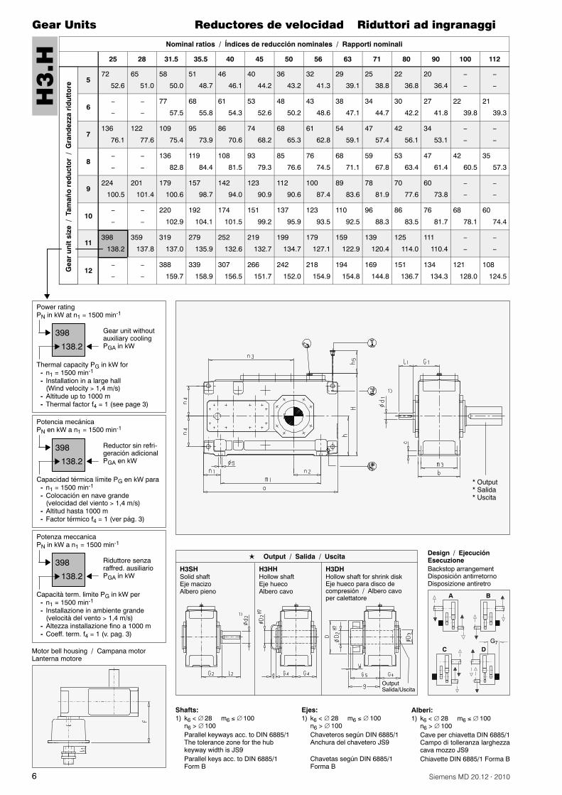
Nominal ratios / Índices de reducción nominales / Rapporti nominali
25 28 31.5 35.5 40 45 50 56 63 71 80 90 100 112G
ear
un
itsi
ze/
Tam
año
red
uct
or
/G
ran
dez
zari
du
tto
re
572
52.6
65
51.0
58
50.0
51
48.7
46
46.1
40
44.2
36
43.2
32
41.3
29
39.1
25
38.8
22
36.8
20
36.4
677
57.5
68
55.8
61
54.3
53
52.6
48
50.2
43
48.6
38
47.1
34
44.7
30
42.2
27
41.8
22
39.8
21
39.3
7136
76.1
122
77.6
109
75.4
95
73.9
86
70.6
74
68.2
68
65.3
61
62.8
54
59.1
47
57.4
42
56.1
34
53.1
8136
82.8
119
84.4
108
81.5
93
79.3
85
76.6
76
74.5
68
71.1
59
67.8
53
63.4
47
61.4
42
60.5
35
57.3
9224
100.5
201
101.4
179
100.6
157
98.7
142
94.0
123
90.9
112
90.6
100
87.4
89
83.6
78
81.9
70
77.6
60
73.8
10220
102.9
192
104.1
174
101.5
151
99.2
137
95.9
123
93.5
110
92.5
96
88.3
86
83.5
76
81.7
68
78.1
60
74.4
11398
138.2
359
137.8
319
137.0
279
135.9
252
132.6
219
132.7
199
134.7
179
127.1
159
122.9
139
120.4
125
114.0
111
110.4
12388
159.7
339
158.9
307
156.5
266
151.7
242
152.0
218
154.9
194
154.8
169
144.8
151
136.7
134
134.3
121
128.0
108
124.5
H3
.H
� Output� Salida� Uscita
Thermal capacity PG in kW for- n1 = 1500 min-1
- Installation in a large hall(Wind velocity 1,4 m/s)
- Altitude up to 1000 m- Thermal factor f4 = 1 (see page 3)
398
138.2
Power ratingPN in kW at n1 = 1500 min-1
Gear unit withoutauxiliary coolingPGA in kW
Capacidad térmica límite PG en kW para- n1 = 1500 min-1
- Colocación en nave grande(velocidad del viento 1,4 m/s)
- Altitud hasta 1000 m- Factor térmico f4 = 1 (ver pág. 3)
398
138.2
Potencia mecánicaPN en kW a n1 = 1500 min-1
Reductor sin refri-geración adicionalPGA en kW
Capacità term. limite PG in kW per- n1 = 1500 min-1
- Installazione in ambiente grande(velocità del vento 1,4 m/s)
- Altezza installazione fino a 1000 m- Coeff. term. f4 = 1 (v. pag. 3)
398
138.2
Potenza meccanicaPN in kW a n1 = 1500 min-1
Riduttore senzaraffred. ausiliarioPGA in kW
Motor bell housing / Campana motorLanterna motore
H3SHSolid shaftEje macizoAlbero pieno
H3HHHollow shaftEje huecoAlbero cavo
H3DHHollow shaft for shrink diskEje hueco para disco decompresión / Albero cavoper calettatore
� Output / Salida / Uscita
OutputSalida/Uscita
A B
C DG7
Design / EjecuciónEsecuzioneBackstop arrangementDisposición antirretornoDisposizione antiretro
Ejes:1) k6 < 28 m6 100
n6 > 100Chaveteros según DIN 6885/1Anchura del chavetero JS9
Chavetas según DIN 6885/1Forma B
Shafts:1) k6 < 28 m6 100
n6 > 100Parallel keyways acc. to DIN 6885/1The tolerance zone for the hubkeyway width is JS9Parallel keys acc. to DIN 6885/1Form B
Alberi:1) k6 < 28 m6 100
n6 > 100Cave per chiavetta DIN 6885/1Campo di tolleranza larghezzacava mozzo JS9Chiavette DIN 6885/1 Forma B
7Siemens MD 20.12 · 2010
Gear Units Reductores de velocidad Riduttori ad ingranaggi
SizeTamañoGrand.
Input / Entrada / EntrataGear unit / Reductor de engranajes
Riduttore a ingranaggiiN = 25 - 45 iN = 50 - 63 iN = 71 - 90iN = 31.5 - 56 iN = 63 - 80 iN = 90 - 112
d1 l1 DS d1 l1 DS d1 l1 DS b c m3 n1 n4 s h -1
5 + 6 40 70 M16 x 36 30 50 M10 x 22 24 40 M8 x 19 255 28 220 105 180 19 230
7 + 8 45 80 M16 x 36 35 60 M12 x 28 28 50 M10 x 22 300 35 260 120 215 24 280
9 + 10 60 125 M20 x 42 45 100 M16 x 36 32 80 M12 x 28 370 40 320 145 245 28 320
11 + 12 70 120 M20 x 42 50 80 M16 x 36 42 70 M16 x 36 430 50 370 165 300 35 380
SizeTamañoGrand.
Gear unit / Reductor de engranajesRiduttore a ingranaggi
Output / Salida / Uscita BackstopAntirretorno
AntiretroH3SH H3HH H3DH
G1 a h5 H m1 n2 n3 G2 G4 d2 l2 DS D2 D2 D3 G5 G7
5 160 690 130 482 480 100 455 165 165 100 210 M24 x 50 95 100 100 240 234
6 160 770 130 482 560 145 490 165 165 110 210 M24 x 50 105 110 110 240 234
7 185 845 170 572 605 130 560 195 195 120 210 M24 x 50 115 120 120 280 287
8 185 950 160 582 710 190 605 195 195 130 250 M24 x 50 125 130 130 285 287
9 230 1000 185 662 710 155 660 235 235 140 250 M30 x 60 135 140 145 330 317
10 230 1100 185 662 810 205 710 235 235 160 300 M30 x 60 150 150 155 350 317
11 255 1200 180 782 870 180 805 270 270 170 300 M30 x 60 165 165 170 400 369
12 255 1355 170 790 1025 265 875 270 270 180 300 M30 x 60 180 180 185 405 369
Motor bell housing / Campana motor / Lanterna motore
SizeTamañoGrand.
MotorMoteur
IEC
iN = iN = iN =
25 - 45 31.5 - 56 50 - 63 63 - 80 71 - 90 90 - 112
BIPEXBWN l1 f BIPEX
BWN l1 f BIPEXBWN l1 f
5 + 6
132 72 302160 84 364 84 338 84 338180 97 364 97 + 44 338 97 + 44 338200 112 + 53 350 112 + 53 350225 127 + 60 391
7 + 8
160 84 367180 97 + 45 367 97 + 45 367200 112 405 112 + 55 379 112 + 55 379225 127 420 127 420 127 420250 127 420 127 420280 142 440.5
9 + 10
180 97 431.5200 112 443.5225 127 519.5 127 484.5 127 484.5250 127 519.5 127 484.5 127 484.5280 142 505 142 505
11 + 12
225 127 489.5250 127 489.5 127 489.5280 142 540 142 510 142 510
315 � 162 577 162 547 162 547
SizeTam.
Grand.
Driven machine shaft / Eje de la máquinaaccionada / Albero macchina operatrice H3HH
Driven machine shaft / Eje de la máquinaaccionada / Albero macchina operatrice H3DH
d2 d4 d5 f1 l l1 r s m g d2 d3 d4 d5 f1 l l1 r HSD W D g
5 95 94.5 105 5 328 40 1.6 2xM10x18 70 40 100 g6 100 h6 99.5 114 5 383 53 2 125-32 20 275 255
6 105 104.5 116 5 328 45 1.6 2xM10x18 70 40 110 g6 110 h6 110 124 5 383 58 3 140-32 20 285 255
7 115 114.5 126 5 388 50 1.6 2xM12x20 80 40 120 g6 120 h6 120 134 5 453 68 3 155-32 23 330 295
8 125 124.5 136 6 388 55 2.5 2xM12x20 85 40 130 g6 130 h6 130 145 6 458 73 3 165-32 23 340 300
9 135 134.5 147 6 467 60 2.5 2xM12x20 90 45 140 g6 145 m6 140 160 6 539 82 4 175-32 28 360 345
10 150 149.5 162 6 467 65 2.5 2xM12x20 110 45 150 g6 155 m6 150 170 6 559 92 4 200-32 28 395 365
11 165 164.5 177 7 537 70 2.5 2xM16x28 120 45 165 f6 170 m6 165 185 7 644 112 4 220-32 30 435 420
12 180 179.5 192 7 537 75 2.5 2xM16x28 130 45 180 f6 185 m6 180 200 7 649 122 4 240-32 30 450 420
A) B) A) C)
A) Material del eje de la máquina accionadaC60N o resistencia superior.
B) La chaveta no es parte de nuestro suministro.C) El disco de compresión y la caperuza de pro-
tección son parte de nuestro suministro.El disco de compresión se suministra suelto.
A) Materiale albero macchina operatrice C60N oresistenza superiore.
B) La chiavetta non fa parte della fornitura.C) Calettatore e coperchio di protezione sono di
nostra fornitura.Il calettatore viene fornito separatamente.
A) Material of driven machine shaft: C60Nor higher strength.
B) Parallel key does not belong to our scopeof supply.
C) Shrink disk and guard are supplied by us.The shrink disk is supplied as loose item.
H3
.H
SizeTamañoGrand.
OilAceiteOlio
WeightPesoPeso
56789
101112
1517283045468590
320 365 540 625 875102014001675
l kg
Dimensions in mm / Medidas en mm / Quote in mm
Sellado:� Entrada: retén radial� Salida: retén radial o
retén Taconite(antipolvo)
Campana motor:� � Motor IEC 315:
solamente tamaños315 S y 315 M
� + Longitud l1 del cubodel acoplamiento,acortado para elmontaje sobre el ejedel reductor
Sealing:� Input: shaft seal� Output: shaft seal or
Taconite seal(dustproof)
Motor bell housing:� � IEC motor 315:
sizes 315 S and315 M only
� + Length l1 of couplinghub shortened forfitting onto gear unitshaft
Guarnizioni� Entrata: anelli tenuta� Uscita: anelli tenuta o
Taconite(antipolvere)
Lanterna motore:� � Motore IEC 315:
solo grandezze315 S e 315 M
� + Lungh l1 del mozzo diaccoppiamento accor-ciato per montaggiosu albero riduttore

8 Siemens MD 20.12 · 2010
Gear Units Reductores de velocidad Riduttori ad ingranaggi
Nominal ratios / Índices de reducción nominales / Rapporti nominali
100 112 125 140 160 180 200 224 250 280 315 355 400 450G
ear
un
itsi
ze/
Tam
año
red
uct
or
Gra
nd
ezza
rid
utt
ore
734
48.8
30
47.1
27
45.8
24
43.6
21
42.0
18
40.5
17
39.0
15
36.8
13
35.1
12
34.1
10
33.4
8.6
31.8
834
52.6
30
50.6
26
49.1
23
46.8
21
45.1
19
43.3
17
41.9
15
39.3
13
37.7
11
36.6
10
35.8
8.7
34.1
956
67.7
50
65.1
44
63.2
39
61.3
35
58.1
31
55.8
28
54.1
25
52.0
22
49.6
20
48.2
17
45.9
15
45.1
1055
68.4
49
65.6
43
63.8
38
61.9
34
58.6
31
56.2
27
54.6
24
52.3
22
50.0
19
48.5
17
46.2
14
45.4
1196
99.1
86
99.2
77
95.5
69
92.9
60
88.6
53
85.9
48
81.3
43
78.2
38
74.3
34
71.5
30
69.7
27
66.3
1298
110.7
87
110.3
76
106.7
67
103.2
61
98.9
54
95.6
49
90.2
44
86.8
39
82.3
34
79.2
31
77.4
26
73.5
H4
.H
� Output� Salida� Uscita
Thermal capacity PG in kW for- n1 = 1500 min-1
- Installation in a large hall(Wind velocity 1,4 m/s)
- Altitude up to 1000 m- Thermal factor f4 = 1 (see page 3)
96
99.1
Power ratingPN in kW at n1 = 1500 min-1
Gear unit withoutauxiliary coolingPGA in kW
Motor bell housing / Campana motorLanterna motore
Capacidad térmica límite PG en kW para- n1 = 1500 min-1
- Colocación en nave grande(velocidad del viento 1,4 m/s)
- Altitud hasta 1000 m- Factor térmico f4 = 1 (ver pág. 3)
96
99.1
Potencia mecánicaPN en kW a n1 = 1500 min-1
Reductor sin refri-geración adicionalPGA en kW
Capacità term. limite PG in kW per- n1 = 1500 min-1
- Installazione in ambiente grande(velocità del vento 1,4 m/s)
- Altezza installazione fino a 1000 m- Coeff. term. f4 = 1 (v. pag. 3)
96
99.1
Potenza meccanicaPN in kW a n1 = 1500 min-1
Riduttore senzaraffred. ausiliarioPGA in kW H4SH
Solid shaftEje macizoAlbero pieno
H4HHHollow shaftEje huecoAlbero cavo
H4DHHollow shaft for shrink diskEje hueco para disco decompresión / Albero cavoper calettatore
� Output / Salida / Uscita
OutputSalida/Uscita
BA
CG7
D
Design / EjecuciónEsecuzioneBackstop arrangementDisposición antirretornoDisposizione antiretro
Ejes:1) k6 < 28 m6 100
n6 > 100Chaveteros según DIN 6885/1Anchura del chavetero JS9
Chavetas según DIN 6885/1Forma B
Shafts:1) k6 < 28 m6 100
n6 > 100Parallel keyways acc. to DIN 6885/1The tolerance zone for the hubkeyway width is JS9Parallel keys acc. to DIN 6885/1Form B
Alberi:1) k6 < 28 m6 100
n6 > 100Cave per chiavetta DIN 6885/1Campo di tolleranza larghezzacava mozzo JS9Chiavette DIN 6885/1 Forma B

9Siemens MD 20.12 · 2010
Gear Units Reductores de velocidad Riduttori ad ingranaggi
SizeTamañoGrand.
Input / Entrada / EntrataGear unit / Reductor de engranajes
Riduttore a ingranaggiiN = 100 - 180 iN = 200 - 355iN = 125 - 224 iN = 250 - 450
d1 l1 DS d1 l1 DS b c m3 n1 n4 s h -1
7 + 8 30 50 M10 x 22 24 40 M8 x 19 300 35 260 120 215 24 280
9 + 10 35 60 M12 x 28 28 50 M10 x 22 370 40 320 145 245 28 320
11 + 12 45 100 M16 x 36 32 80 M12 x 28 430 50 370 165 300 35 380
SizeTamañoGrand.
Gear unit / Reductor de engranajesRiduttore a ingranaggi
Output / Salida / Uscita BackstopAntirretorno
AntiretroH4SH H4HH H4DH
G1 a h5 H m1 n2 n3 G2 G4 d2 l2 DS D2 D2 D3 G5 G7
7 180 845 140 572 605 130 560 195 195 120 210 M24 x 50 115 120 120 280 286
8 180 950 140 582 710 190 605 195 195 130 250 M24 x 50 125 130 130 285 286
9 215 1000 150 662 710 155 660 235 235 140 250 M30 x 60 135 140 145 330 317
10 215 1100 150 662 810 205 710 235 235 160 300 M30 x 60 150 150 155 350 317
11 250 1200 165 782 870 180 805 270 270 170 300 M30 x 60 165 165 170 400 333
12 250 1355 165 790 1025 265 875 270 270 180 300 M30 x 60 180 180 185 405 333
Motor bell housing / Campana motor / Lanterna motore
SizeTamañoGrand.
MotorMoteur
IEC
iN = iN =
100 - 180 125 - 224 200 - 355 250 - 450
BIPEXBWN
l1 f BIPEXBWN
l1 f
7 + 8
100 62 296
112 62 296
132 72 328.5 72 328.5
160 84 364.5 84 364.5
180 97 + 42 364.5
9 + 10
132 72 369.5
160 84 405.5 84 405.5
180 97 + 47 405.5 97 + 47 405.5
200 112 + 54 417.5
225 127 + 59 417.5
11 + 12
160 84 447.5
180 97 437.5 97 447.5
200 112 485.5 112 459.5
225 127 500.5 127 500.5
250 127 500.5
SizeTam.
Grand.
Driven machine shaft / Eje de la máquinaaccionada / Albero macchina operatrice H4HH Driven machine shaft / Eje de la máquina
accionada / Albero macchina operatrice H4DH
d2 d4 d5 f1 l l1 r s m g d2 d3 d4 d5 f1 l l1 r HSD W D g
7 115 114.5 126 5 388 50 1.6 2xM12x20 80 40 120 g6 120 h6 120 134 5 453 68 3 155-32 23 330 295
8 125 124.5 136 6 388 55 2.5 2xM12x20 85 40 130 g6 130 h6 130 145 6 458 73 3 165-32 23 340 300
9 135 134.5 147 6 467 60 2.5 2xM12x20 90 45 140 g6 145 m6 140 160 6 539 82 4 175-32 28 360 345
10 150 149.5 162 6 467 65 2.5 2xM12x20 110 45 150 g6 155 m6 150 170 6 559 92 4 200-32 28 395 365
11 165 164.5 177 7 537 70 2.5 2xM16x28 120 45 165 f6 170 m6 165 185 7 644 112 4 220-32 30 435 420
12 180 179.5 192 7 537 75 2.5 2xM16x28 130 45 180 f6 185 m6 180 200 7 649 122 4 240-32 30 450 420
A) B) A) C)
A) Material del eje de la máquina accionadaC60N o resistencia superior.
B) La chaveta no es parte de nuestro suministro.C) El disco de compresión y la caperuza de pro-
tección son parte de nuestro suministro.El disco de compresión se suministra suelto.
A) Materiale albero macchina operatrice C60N oresistenza superiore.
B) La chiavetta non fa parte della fornitura.C) Calettatore e coperchio di protezione sono di
nostra fornitura.Il calettatore viene fornito separatamente.
A) Material of driven machine shaft: C60Nor higher strength.
B) Parallel key does not belong to our scopeof supply.
C) Shrink disk and guard are supplied by us.The shrink disk is supplied as loose item.
H4
.H
SizeTamañoGrand.
OilAceiteOlio
WeightPesoPeso
7
8
9
10
11
12
25
27
48
50
80
87
550
645
875
1010
1460
1725
l kg
Dimensions in mmMedidas en mmQuote in mm
Sealing:� Input: shaft seal� Output: shaft seal or Taconite
seal (dustproof)
Motor bell housing:� + Length l1 of coupling hub
shortened for fitting onto gearunit shaft
Sellado:� Entrada: retén radial� Salida: retén radial o retén
Taconite (antipolvo)
Campana motor:� + Longitud l1 del cubo del
acoplamiento, acortado parael montaje sobre el eje delreductor
Guarnizioni� Entrata: anelli tenuta� Uscita: anelli tenuta o Taconite(antipolvere)
Lanterna motore:� + Lungh l1 del mozzo di
accoppiamento accorciato permontaggio su albero riduttore

10 Siemens MD 20.12 · 2010
Gear Units Reductores de velocidad Riduttori ad ingranaggi
Nominal ratios / Índices de reducción nominales / Rapporti nominali
12.5 14 16 18 20 22.4 25 28 31.5 35.5 40 45 50 56 63 71 80 90G
ear
un
itsi
ze/
Tam
año
red
uct
or
/G
ran
dez
zari
du
tto
re
5118
50.5118.2
10949.7
114.9
10348.4
110.8
9847.2
107.7
9145.6
103.5
8145.2
102.0
7243.496.7
6542.593.3
5840.788.5
5138.683.0
4633.771.7
4032.969.9
3633.169.2
3230.764.1
2829.661.6
2428.258.5
6118
55.5126.6
10954.2
122.9
10352.6
118.6
9951.4
115.3
9750.1
110.9
8750.0
109.6
7747.8
103.7
6846.599.9
6144.494.6
5341.888.6
4836.977.0
4336.275.1
3836.074.3
3433.368.4
2732.065.9
2430.562.7
7213
76.7186.7
20375.7
180.8
19472.9
172.9
18371.1
167.8
17068.9
161.2
15267.2
156.0
13666.2
151.2
12264.1
143.2
10961.7
136.2
9559.2
129.1
8652.1
112.2
7450.8
108.4
6850.8
106.9
6147.599.5
5346.196.2
4344.091.7
8211
83.4196.8
20081.2
191.9
19678.1
182.7
18576.7
177.7
17075.3
170.4
15374.4
165.9
13672.8
161.0
11969.9
152.8
10867.1
145.0
9364.1
137.1
8556.9
119.6
7655.8
116.2
6855.3
114.3
5951.4
106.1
5249.8
102.6
4447.597.6
9351
95.5250.6
33095.3
244.4
30594.3
239.9
29492.5
232.5
28089.9
223.7
25088.7
219.0
22487.0
209.4
20185.1
199.7
17982.8
190.7
15779.6
181.3
14275.0
168.7
12369.4
154.5
11269.4
151.0
10064.8
140.3
8962.8
135.5
7459.0
126.9
10350103.1262.9
32596.4
243.3
308100.2251.4
29393.9
231.6
27592.8
223.9
24793.1
220.2
22090.8
210.2
19287.7
199.6
17484.4
191.4
15180.8
180.3
13777.1
169.8
12372.0
155.8
11071.0
151.7
9666.0
140.9
8663.9
136.2
7560.1
127.7
11658112.8377.4
635117.3374.9
589114.4358.8
538115.4353.2
498112.7339.4
445110.4324.0
398109.8307.7
359109.3296.4
319107.0282.2
279105.1271.2
252100.5255.1
21993.2
234.6
19995.9
232.4
17988.9
211.9
15986.4
203.7
13180.3
189.3
12652125.3407.7
604129.5411.1
570124.5385.3
530128.4388.5
485130.5375.9
436132.0364.0
388129.1344.2
339126.0328.5
307121.3310.2
266118.1298.8
242115.3281.8
218108.3260.7
194108.4255.7
16999.9
232.6
15195.8
224.2
13189.7
208.4
B3
.H
FanVentiladorVentola
Air inletEntrada de aireEntrata aria
� Output� Salida� Uscita
Thermal capacity PG in kW for- n1 = 1500 min-1
- Installation in a large hall(Wind velocity 1,4 m/s)
- Altitude up to 1000 m- Thermal factor f4 = 1 (see page 3)
658112.8
Power ratingPN in kW at n1 = 1500 min-1
Gear unit withoutauxiliary coolingPGA in kW
Gear unit with fanPGB in kW377.4
Capacidad térmica límite PG en kW para- n1 = 1500 min-1
- Colocación en nave grande(velocidad del viento 1,4 m/s)
- Altitud hasta 1000 m- Factor térmico f4 = 1 (ver pág. 3)
658112.8
Potencia mecánicaPN en kW a n1 = 1500 min-1
Reductor sin refrige-ración adicionalPGA en kW
Reductor con venti-lador PGB en kW377.4
Capacità term. limite PG in kW per- n1 = 1500 min-1
- Installazione in ambiente grande(velocità del vento 1,4 m/s)
- Altezza installazione fino a 1000 m- Coeff. term. f4 = 1 (v. pag. 3)
658112.8
Potenza meccanicaPN in kW a n1 = 1500 min-1
Riduttore senzaraffred. ausiliarioPGA in kW
Riduttore con ventolaPGB in kW377.4
B3SHSolid shaftEje macizoAlbero pieno
B3HHHollow shaftEje huecoAlbero cavo
B3DHHollow shaft for shrink diskEje hueco para disco decompresión / Albero cavoper calettatore
� Output / Salida / Uscita
Motor bell housing / Campana motorLanterna motore
OutputSalida/Uscita
G7A B
C D
Design / EjecuciónEsecuzioneBackstop arrangementDisposición antirretornoDisposizione antiretro
Ejes:1) k6 < 28 m6 100
n6 > 100Chaveteros según DIN 6885/1Anchura del chavetero JS9
Chavetas según DIN 6885/1Forma B
Shafts:1) k6 < 28 m6 100
n6 > 100Parallel keyways acc. to DIN 6885/1The tolerance zone for the hubkeyway width is JS9Parallel keys acc. to DIN 6885/1Form B
Alberi:1) k6 < 28 m6 100
n6 > 100Cave per chiavetta DIN 6885/1Campo di tolleranza larghezzacava mozzo JS9Chiavette DIN 6885/1 Forma B

11Siemens MD 20.12 · 2010
Gear Units Reductores de velocidad Riduttori ad ingranaggi
SizeTamañoGrand.
Input / Entrada / EntrataGear unit / Reductor de engranajes
Riduttore a ingranaggiiN = 12.5 - 45 iN = 50 - 71iN = 16 - 56 iN = 63 - 90
d1 l1 l3 DS d1 l1 l3 DS A1 A2 b B1 c d6 m3 n1 n4 s h -1
5 + 6 35 80 60 M12 x 28 28 60 40 M10 x 22 220 235 255 168 28 130 220 105 180 19 230
7 + 8 45 100 80 M16 x 36 35 80 60 M12 x 28 275 275 300 193 35 165 260 120 215 24 280
9 + 10 55 110 80 M20 x 42 40 100 70 M16 x 36 315 325 370 231 40 175 320 145 245 28 320
11 + 12 70 135 105 M20 x 42 50 110 80 M16 x 36 370 385 430 263 50 190 370 165 300 35 380
SizeTamañoGrand.
Gear unit / Reductor de engranajesRiduttore a ingranaggi
Output / Salida / Uscita BackstopAntirretorno
AntiretroB3SH B3HH B3DH
G1 G3 a G6 h5 H m1 n2 n3 G2 G4 d2 l2 DS D2 D2 D3 G5 G7
5 575 595 640 605 130 482 430 100 405 165 165 100 210 M24 x 50 95 100 100 240 223
6 610 630 720 640 130 482 510 145 440 165 165 110 210 M24 x 50 105 110 110 240 223
7 690 710 785 720 170 572 545 130 500 195 195 120 210 M24 x 50 115 120 120 280 281
8 735 755 890 765 160 582 650 190 545 195 195 130 250 M24 x 50 125 130 130 285 281
9 800 830 925 845 175 662 635 155 585 235 235 140 250 M30 x 60 135 140 145 330 317
10 850 880 1025 895 175 662 735 205 635 235 235 160 300 M30 x 60 150 150 155 350 317
11 960 990 1105 1010 220 782 775 180 710 270 270 170 300 M30 x 60 165 165 170 400 368
12 1030 1060 1260 1080 210 790 930 265 780 270 270 180 300 M30 x 60 180 180 185 405 368
Motor bell housing / Campana motor / Lanterna motore
SizeTamañoGrand.
MotorMoteur
IEC
iN = iN =
BIPEXBWN
12.5 - 45 16 - 56 BIPEXBWN
50 - 71 63 - 90f fL f fL
5 + 6
160 84 771.5 806.5 84 771.5 806.5180 97 771.5 806.5 97 771.5 806.5200 112 782.5 818.5 112 782.5 818.5225 127 824.5 859.5
7 + 8
160 84 903.5 948.5180 97 903.5 948.5200 112 909.5 954.5 112 909.5 945.5225 127 950.5 995.5 127 935.5 980.5250 127 952 997 127 935.5 980.5280 142 971 1016
9 + 10
200 112 1035 1085225 127 1076 1126 127 1076 1126250 127 1077 1127 127 1077 1127280 142 1096 1146 142 1076 1126
11 + 12
225 127 1244 1314250 142 1260 1330 127 1244 1314280 142 1279 1349 142 1229 1299
315 � 162 1316 1386 162 1266 1336
SizeTam.
Grand.
Driven machine shaft / Eje de la máquinaaccionada / Albero macchina operatrice B3HH
Driven machine shaft / Eje de la máquinaaccionada / Albero macchina operatrice B3DH
d2 d4 d5 f1 l l1 r s m g d2 d3 d4 d5 f1 l l1 r HSD W D g
5 95 94.5 105 5 328 40 1.6 2xM10x18 70 40 100 g6 100 h6 99.5 114 5 383 53 2 125-32 20 275 255
6 105 104.5 116 5 328 45 1.6 2xM10x18 70 40 110 g6 110 h6 110 124 5 383 58 3 140-32 20 285 255
7 115 114.5 126 5 388 50 1.6 2xM12x20 80 40 120 g6 120 h6 120 134 5 453 68 3 155-32 23 330 295
8 125 124.5 136 6 388 55 2.5 2xM12x20 85 40 130 g6 130 h6 130 145 6 458 73 3 165-32 23 340 300
9 135 134.5 147 6 467 60 2.5 2xM12x20 90 45 140 g6 145 m6 140 160 6 539 82 4 175-32 28 360 345
10 150 149.5 162 6 467 65 2.5 2xM12x20 110 45 150 g6 155 m6 150 170 6 559 92 4 200-32 28 395 365
11 165 164.5 177 7 537 70 2.5 2xM16x28 120 45 165 f6 170 m6 165 185 7 644 112 4 220-32 30 435 420
12 180 179.5 192 7 537 75 2.5 2xM16x28 130 45 180 f6 185 m6 180 200 7 649 122 4 240-32 30 450 420
A) B) A) C)
A) Material del eje de la máquina accionadaC60N o resistencia superior.
B) La chaveta no es parte de nuestro suministro.C) El disco de compresión y la caperuza de pro-
tección son parte de nuestro suministro.El disco de compresión se suministra suelto.
A) Materiale albero macchina operatrice C60N oresistenza superiore.
B) La chiavetta non fa parte della fornitura.C) Calettatore e coperchio di protezione sono di
nostra fornitura.Il calettatore viene fornito separatamente.
A) Material of driven machine shaft: C60Nor higher strength.
B) Parallel key does not belong to our scopeof supply.
C) Shrink disk and guard are supplied by us.The shrink disk is supplied as loose item.
B3
.H
SizeTamañoGrand.
OilAceiteOlio
WeightPesoPeso
56789
101112
1415252840426672
325 380 550 635 890102014551730
l kg
Sellado:� Retén radial o retén Taconite
antipolvo)
Campana motor:� No combinable con ventilador
ni retén Taconite en entrada� � Motor IEC 315: solamente
tamaños 315 S y 315 M
Dimensions in mmMedidas en mmQuote in mm
Sealing:� Shaft seal or Taconite seal
(dustproof)
Motor bell housing:� Not in combination with fan and/
or Taconite seal on input side� � IEC motor 315: sizes 315 S
and 315 M only
Guarnizioni:� Anelli tenuta o Taconite
(antipolvere)
Lanterna motore:� Non in combinazione con
ventola e/o tenute Taconite inentrata
� � Motore IEC 315: solograndezze 315 S e 315 M
12 Siemens MD 20.12 · 2010
Gear Units Reductores de velocidad Riduttori ad ingranaggi
Nominal ratios / Índices de reducción nominales / Rapporti nominali
80 90 100 112 125 140 160 180 200 224 250 280 315 355 400G
ear
un
itsi
ze/
Tam
año
red
uct
or
/G
ran
dez
zari
du
tto
re
522
31.8
20
31.1
18
29.7
16
28.7
14
27.4
12
26.2
11
24.1
10
23.7
9.1
22.9
8.1
21.3
7.2
20.9
6.5
19.9
5.6
18.6
624
34.1
21
33.3
19
31.9
17
30.8
15
29.4
13
28.2
12
25.9
10
25.5
9.7
24.5
8.7
23.0
7.7
22.4
6.8
21.4
5.7
20.0
742
47.0
37
45.6
34
43.2
30
41.6
27
39.8
24
37.9
21
34.6
18
33.8
17
33.5
15
31.3
13
30.3
12
28.4
10
26.6
842
50.2
38
48.8
34
46.3
30
44.7
26
42.7
23
40.7
21
37.2
19
36.4
17
36.1
15
33.8
13
32.5
11
30.5
10
28.6
970
66.1
62
64.8
56
61.5
50
59.3
44
56.7
39
53.5
35
49.0
31
47.9
28
47.1
25
44.1
22
42.6
19
40.7
17
38.2
1069
66.7
62
65.3
55
62.1
49
59.9
43
57.2
38
54.4
34
49.9
31
48.7
27
47.8
24
44.8
22
43.3
19
41.3
17
38.9
11121
98.6
107
95.9
96
92.5
86
88.3
77
84.8
69
80.5
60
73.6
53
71.9
48
70.5
43
66.5
38
64.6
34
61.9
30
57.8
12122
110.2
109
106.8
98
102.3
87
97.9
76
94.1
67
89.4
61
82.0
54
80.2
49
78.6
44
74.1
39
71.7
34
68.4
29
63.9
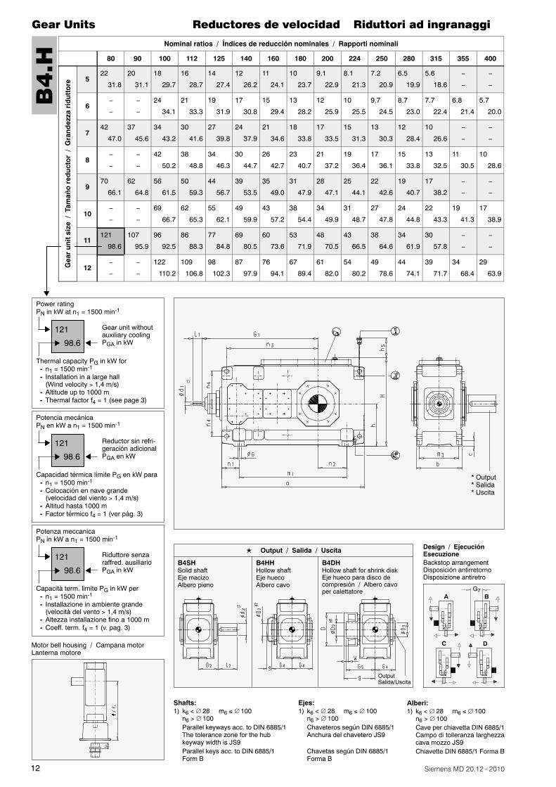
B4
.H
� Output� Salida� Uscita
Thermal capacity PG in kW for- n1 = 1500 min-1
- Installation in a large hall(Wind velocity 1,4 m/s)
- Altitude up to 1000 m- Thermal factor f4 = 1 (see page 3)
121
98.6
Power ratingPN in kW at n1 = 1500 min-1
Gear unit withoutauxiliary coolingPGA in kW
B4SHSolid shaftEje macizoAlbero pieno
B4HHHollow shaftEje huecoAlbero cavo
B4DHHollow shaft for shrink diskEje hueco para disco decompresión / Albero cavoper calettatore
� Output / Salida / Uscita
Motor bell housing / Campana motorLanterna motore
Capacidad térmica límite PG en kW para- n1 = 1500 min-1
- Colocación en nave grande(velocidad del viento 1,4 m/s)
- Altitud hasta 1000 m- Factor térmico f4 = 1 (ver pág. 3)
121
98.6
Potencia mecánicaPN en kW a n1 = 1500 min-1
Reductor sin refri-geración adicionalPGA en kW
Capacità term. limite PG in kW per- n1 = 1500 min-1
- Installazione in ambiente grande(velocità del vento 1,4 m/s)
- Altezza installazione fino a 1000 m- Coeff. term. f4 = 1 (v. pag. 3)
121
98.6
Potenza meccanicaPN in kW a n1 = 1500 min-1
Riduttore senzaraffred. ausiliarioPGA in kW
OutputSalida/Uscita
G7BA
C D
Design / EjecuciónEsecuzioneBackstop arrangementDisposición antirretornoDisposizione antiretro
Ejes:1) k6 < 28 m6 100
n6 > 100Chaveteros según DIN 6885/1Anchura del chavetero JS9
Chavetas según DIN 6885/1Forma B
Shafts:1) k6 < 28 m6 100
n6 > 100Parallel keyways acc. to DIN 6885/1The tolerance zone for the hubkeyway width is JS9Parallel keys acc. to DIN 6885/1Form B
Alberi:1) k6 < 28 m6 100
n6 > 100Cave per chiavetta DIN 6885/1Campo di tolleranza larghezzacava mozzo JS9Chiavette DIN 6885/1 Forma B
13Siemens MD 20.12 · 2010
Gear Units Reductores de velocidad Riduttori ad ingranaggi
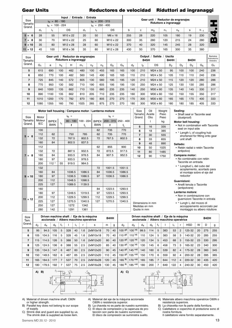
SizeTamañoGrand.
Input / Entrada / EntrataGear unit / Reductor de engranajes
Riduttore a ingranaggiiN = 80 - 180 iN = 200 - 315iN = 100 - 224 iN = 250 - 400
d1 l1 DS d1 l1 DS b c m3 n1 n4 s h -1
5 + 6 28 55 M10 x 22 20 50 M6 x 16 255 28 220 105 180 19 230
7 + 8 30 70 M10 x 22 25 60 M10 x 22 300 35 260 120 215 24 280
9 + 10 35 80 M12 x 28 28 60 M10 x 22 370 40 320 145 245 28 320
11 + 12 45 100 M16 x 36 35 80 M12 x 28 430 50 370 165 300 35 380
SizeTamañoGrand.
Gear unit / Reductor de engranajesRiduttore a ingranaggi
Output / Salida / Uscita BackstopAntirretorno
AntiretroB4SH B4HH B4DH
G1 a h5 H m1 n2 n3 G2 G4 d2 l2 DS D2 D2 D3 G5 G7
5 615 690 100 482 480 100 455 165 165 100 210 M24 x 50 95 100 100 240 236
6 650 770 100 482 560 145 490 165 165 110 210 M24 x 50 105 110 110 240 236
7 725 845 140 572 605 130 560 195 195 120 210 M24 x 50 115 120 120 280 286
8 770 950 130 582 710 190 605 195 195 130 250 M24 x 50 125 130 130 285 286
9 840 1000 135 662 710 155 660 235 235 140 250 M30 x 60 135 140 145 330 317
10 890 1100 135 662 810 205 710 235 235 160 300 M30 x 60 150 150 155 350 317
11 1010 1200 170 782 870 180 805 270 270 170 300 M30 x 60 165 165 170 400 333
12 1080 1355 160 790 1025 265 875 270 270 180 300 M30 x 60 180 180 185 405 333
Motor bell housing / Campana motor / Lanterna motore
SizeTamañoGrand.
MotorMoteur
IEC
iN = iN =
BIPEXBWN l1
80 - 180 100 - 224 BIPEXBWN
200 - 315 250 - 400f fL f fL
5 + 6
100 62 735 770112 62 750 785 62 735 770132 72 767.5 802.5 72 767.5 802.5160 84 802.5 837.5
7 + 8
112 62 855 900132 72 887.5 932.5 72 872.5 917.5160 84 933.5 978.5 84 907.5 952.5180 97 933.5 978.5200 112 + 55 919.5 964.5
9 + 10
132 72 1001.5 1051.5160 84 1036.5 1086.5 84 1036.5 1086.5180 97 1036.5 1086.5 97 1036.5 1086.5200 112 1048.5 1098.5225 127 1089.5 1139.5
11 + 12
160 84 1223.5 1293.5180 97 1249.5 1319.5 97 1223.5 1293.5200 112 1229.5 1299.5 112 1229.5 1299.5225 127 1270.5 1340.5 127 1270.5 1340.5250 127 1272 1342280 142 1291 1361
SizeTam.
Grand.
Driven machine shaft / Eje de la máquinaaccionada / Albero macchina operatrice B4HH
Driven machine shaft / Eje de la máquinaaccionada / Albero macchina operatrice B4DH
d2 d4 d5 f1 l l1 r s m g d2 d3 d4 d5 f1 l l1 r HSD W D g
5 95 94.5 105 5 328 40 1.6 2xM10x18 70 40 100 g6 100 h6 99.5 114 5 383 53 2 125-32 20 275 255
6 105 104.5 116 5 328 45 1.6 2xM10x18 70 40 110 g6 110 h6 110 124 5 383 58 3 140-32 20 285 255
7 115 114.5 126 5 388 50 1.6 2xM12x20 80 40 120 g6 120 h6 120 134 5 453 68 3 155-32 23 330 295
8 125 124.5 136 6 388 55 2.5 2xM12x20 85 40 130 g6 130 h6 130 145 6 458 73 3 165-32 23 340 300
9 135 134.5 147 6 467 60 2.5 2xM12x20 90 45 140 g6 145 m6 140 160 6 539 82 4 175-32 28 360 345
10 150 149.5 162 6 467 65 2.5 2xM12x20 110 45 150 g6 155 m6 150 170 6 559 92 4 200-32 28 395 365
11 165 164.5 177 7 537 70 2.5 2xM16x28 120 45 165 f6 170 m6 165 185 7 644 112 4 220-32 30 435 420
12 180 179.5 192 7 537 75 2.5 2xM16x28 130 45 180 f6 185 m6 180 200 7 649 122 4 240-32 30 450 420
A) B) A) C)
A) Material del eje de la máquina accionadaC60N o resistencia superior.
B) La chaveta no es parte de nuestro suministro.C) El disco de compresión y la caperuza de pro-
tección son parte de nuestro suministro.El disco de compresión se suministra suelto.
A) Materiale albero macchina operatrice C60N oresistenza superiore.
B) La chiavetta non fa parte della fornitura.C) Calettatore e coperchio di protezione sono di
nostra fornitura.Il calettatore viene fornito separatamente.
A) Material of driven machine shaft: C60Nor higher strength.
B) Parallel key does not belong to our scopeof supply.
C) Shrink disk and guard are supplied by us.The shrink disk is supplied as loose item.
B4
.H
SizeTamañoGrand.
OilAceiteOlio
WeightPesoPeso
56789
101112
1618303348508090
335 385 555 655 890102514851750
l kg
Dimensions in mmMedidas en mmQuote in mm
Sellado:� Retén radial o retén Taconite
antipolvo)
Campana motor:� No combinable con retén
Taconite en entrada� + Longitud l1 del cubo del
acoplamiento, acortado parael montaje sobre el eje delreductor
Guarnizioni:� Anelli tenuta o Taconite
(antipolvere)
Lanterna motore:� Non in combinazione con
guarnizioni Taconite in entrata� + Lungh l1 del mozzo di
accoppiamento accorciato permontaggio su albero riduttore
Sealing:� Shaft seal or Taconite seal
(dustproof)
Motor bell housing:� Not in combination with Taconite
seal on input side� + Length l1 of coupling hub
shortened for fitting onto gearunit shaft
14 Siemens MD 20.12 · 2010
Gear Units
Notes
Reductores de velocidad
Notas
Riduttori ad ingranaggi
Notas
............................................................................
............................................................................
............................................................................
............................................................................
............................................................................
............................................................................
............................................................................
............................................................................
............................................................................
............................................................................
............................................................................
............................................................................
............................................................................
............................................................................
............................................................................
............................................................................
............................................................................
............................................................................
............................................................................
............................................................................
............................................................................
............................................................................
............................................................................
............................................................................
............................................................................
............................................................................
............................................................................
............................................................................
............................................................................
............................................................................
............................................................................
............................................................................
............................................................................
............................................................................
............................................................................
............................................................................
............................................................................
............................................................................
............................................................................
............................................................................
............................................................................
............................................................................
............................................................................
............................................................................
............................................................................
............................................................................
............................................................................
............................................................................
............................................................................
............................................................................
............................................................................
............................................................................
............................................................................
............................................................................
............................................................................
............................................................................
............................................................................
15Siemens MD 20.12 · 2010
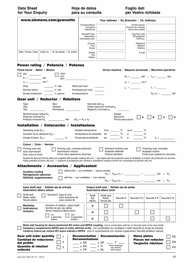
Data Sheetfor Your Enquiry
Hoja de datospara su consulta
Foglio datiper Vostra richiesta
Motor bell housing for above-mentioned IEC motor and BIPEX coupling (not in combination with fan or Taconite seal on the input shaft)Campana y acoplamiento BIPEX para el motor definido arriba (no combinable con ventilador o retén taconite en el eje de entrada)Lanterna motore per motore IEC sopra indicato e BIPEX (non in combinazione con ventola a guarnizioni Taconite all’albero veloce)
BackstopAntirretornoAntiretro
Direction of rotation, output shaftSentido de giro eje salidaSenso rotazione albero lento
cwa derechasdestro
ccwa izquierdassinistro
Input shaft seal / Sellado eje de entradaGuarnizioni albero veloce
Output shaft seal / Sellado eje de salidaGuarnizioni albero lento
Shaft sealRetén radialTenute albero
Taconite E (type B only)(solo reductores B)(solo riduttori B)
Shaft sealRetén
Tenute alb.
ShaftEje
AlberoTaconite F Taconite F-H Taconite F-F Taconite F-K
S
H
D
Auxiliary coolingRefrigeración adicionalRaffredd. supplementare
without fan / sin ventilador / senza ventolaPG = PGA x f4 = ____________ = _________ kW > P2
with fan / con ventilador / con ventolaPG = PGB x f4 = ____________ = _________ kW > P2
Colour / Color / Vernice
Installation / Colocación / Installazione
Priming coat onlySolo imprimaciónSolo mano di fondo
Priming coat, overseas shipmentImprimación marinaPrima mano spedizione oltremare
Standard finishing coatAcabado estándarFinitura standard
Finishing coat, overseasAcabado marinoFinitura per spedizione oltremare
Guards for fans and shrink disks are supplied with powder coating (40 �m) / Las caperuzas de protección para el ventilador y el disco de protección se suminis-trarán pintados al polvo (40 �m) / l coperchi di protezione per ventola e calettatore vengono formiti con verniciatura a polvere (40 �m)
www.siemens.com/gearunits
ADesignEjecuciónForma esecuzione
B C D
Operating cycle ED =
Duración de la utilización ED =
Durata d’inserz. ED = _______ %
Ambient temperature from _______ C up to _______ C
Temperatura de ambiente de _______ C a _______ C
Temperatura ambiente da _______ C a _______ C f4 = __________
TypeTipoTipo ____________
SizeTamañoGrandezza ___________
Nominal power rating PNPotencia nominal PNPotenza nominale PN ____________ kW (PN >= P2 x f1)
Nominal ratio iNÍndice reducción nominal iNRapporto nominale iN _________
Gear unit / Reductor / Riduttore
Power rating / Potencia / Potenza
Prime mover / Motor / Motore
IEC _________
P1 = _________ kW
otherotroaltro _________________
n1 = _________ min-1
Duty: _______ h / day
Servicio diario: _______ h / dia
Durata d’esercizio: _______ h / giorno
Starts per hour: _______
Arranques por hora: _______
Avviamenti/ora: _______
Driven machine / Máquina accionada / Macchina operatrice
P2 = _______ kW
n2 = _______ min-1
is = _______
T2 = _______ Nm
f1 = _______
P2 x f1 = _______ kW
Date / Fecha / Data Order no. / N de pedido / N ordine
Attachments / Accesorios / Applicazioni
Company/NameCompañía
Ditta/Nome
Contact personPersona de contacto
Nome del contatto
Street/PO BoxCalle/Apdo.
Via/Casella post.
City/Post codeCP/población
CAP/Loc.
CountryPaís
Paese
TelephoneTeléfonoTelefono
TelefaxFax
Telefax
Your address / Su dirección / Vs. indirizzo
/
Documentation / DocumentaciónDocumentazione
____ x DE
Name plates
Placas del reductor
Targhette riduttore____ x EN____ x FR
(other language)(otro idioma)(altra lingua)
____ x ____
DE
EN
FR
____ x SP____ x IT____ x NL
Gear unit order quantity
Cantidad de reductoresdel pedido
Quantita di riduttoriordinata
1
2
3


Gear Units Reductores de velocidadRiduttori ad ingranaggi Fast Track
Catalog MD 20.12 · 2010
FLENDER gear units
www.siemens.com/drivetechnology
Subject to change without prior notice Order No.: E86060-K5720-A221-A1-7R00Dispo 18407KG 0810 2.0 Ro 18 En/Es/ItPrinted in Germany© Siemens AG 2010
Siemens AGIndustry SectorDrive Technologies DivisionMechanical DrivesPostfach 136446393 BOCHOLTGERMANY
The information provided in this catalog contains descriptions or characteristics of performance which in case of actual use do not always apply as described or which may change as a result of further development of the products. An obligation to provide the respective characteristics shall only exist if expressly agreed in the terms of contract. Availability and technical specifications are subject to change without notice.All product designations may be trademarks or product names of Siemens AG or supplier companies whose use by third parties for their own purposes could violate the rights of the owners.
Este catálogo contiene descripciones o prestaciones que en el caso de aplicación concreta pueden no coincidir exactamente con lo descrito, o bien haber sido modificadas como consecuencia de un ulterior desarrollo del producto. Por ello, la presencia de las prestaciones deseadas sólo será vinculante si se ha estipulado expresamente al concluir el contrato. Reservada la posibilidad de suministro y modificaciones técnicas.Todos los nombres de productos pueden ser marcas registradas o nombres protegidos de Siemens AG u otras empresas proveedoras suyas cuyo uso por terceros para sus fines puede violar los derechos de sus titulares.
Le informazioni riportate in questo catalogo contengono descrizioni o caratteristiche che potrebbero variare con l’evolversi dei prodotti o non essere sempre appropriate, nella forma descritta, per il caso applicativo concreto. Le caratteristiche richieste saranno da considerare impegnative solo se espressamente concordate in fase di definizione del contratto. Con riserva di disponibilità di fornitura e modifiche tecniche.Tutte le denominazioni dei prodotti possono essere marchi oppure denominazioni di prodotti della Siemens AG o di altre ditte fornitrici, il cui utilizzo da parte di terzi per propri scopi può violare il diritto dei proprietari.
Answers for industry.
AUD_MD_20.12_umschlag_A4_ES_EN_IT.indd 1 11.08.10 10:08