gearbox 2 high-speed shaft loads analysis · shaft alignment handbook, third edition, crc press,...
TRANSCRIPT

NREL is a national laboratory of the U.S. Department of Energy, Office of Energy Efficiency and Renewable Energy, operated by the Alliance for Sustainable Energy, LLC.
Gearbox 2 High-Speed Shaft Loads Analysis
Latha Sethuraman1, Jon Keller1 , Yi Guo1, and Brian McNiff2
1National Renewable Energy Laboratory
2McNiff Light Industry
Gearbox Reliability Collaborative All-Members Meeting Boulder, Colorado
February 17‒18, 2015

2
Gearbox Reliability Collaborative (GRC) Research Motivation
48%
13%
0% 7% 2%
18%
7% 1% 1%
2% 1%
HSS BEARINGS
INTER-MEDIATE SHAFTBEARINGSLOW SPEED SHAFT BEARINGS
PLANET BEARING
PLANET CARRIER BEARING
HELICAL GEAR
PLANET GEAR
RING GEAR
INTERNAL SHAFT
HSS COUPLING
Failure % - Data based on 257 gearbox damage records in GRC database (Sheng 2013)
HSS bearings
Safe area of bearing operation, reproduced from (Stadler and Baum 2014)
• High failure rates and repair costs of high-speed shaft (HSS) bearings o HSS bearings represent nearly 28%
of the total cost over the different failure modes for a wind gearbox
(Horenbeek et al. 2014) • Common bearing failure modes
(Stadler and Baum 2014) o White etch cracking o Skidding
• Reasons o Combinations of speed and loading beyond the “safe
area” o Impact loads, transient events or torque reversals can
occur up to 15,000 times per year (Gearsolutions.com 2010)
o HSS shaft/coupling misalignment o Mismatch between actual loads and design loads.

3
Objectives
• GRC Phase 3 focused on identifying any abnormal loading on the gear, shaft, and bearings on the HSS stage.
• HSS section of the GRC gearbox 2 was instrumented and tested under
different loading conditions. The measurements were used to: o Validate models against dynamometer test data
– First shaft torque and bending, then bearing loads – First SIMPACK, then Transmission3D
• Establish and validate the relationships between external measurements
of shaft loads and bearing loads o INDIRECT APPROACH: Can invasive instrumentation be avoided in future?

4
GRC HSS Instrumentation
Slip rings Pinion tooth strain for Gear Khβ
Bearing strain for relative loading (four axial slots, two Poisson gauges per slot)
and temperature (both bearings)
Shaft bending strain (two axes, three axial locations)
and shaft torsion for torque
Encoder for azimuth and speed
Photo by Scott Naucler, NREL 26259
Photo by Jon Keller, NREL 27895
Photo by Scott Naucler, NREL 30252
Photo by Scott Naucler, NREL 30250
Photo by Scott Naucler, NREL 30251
5
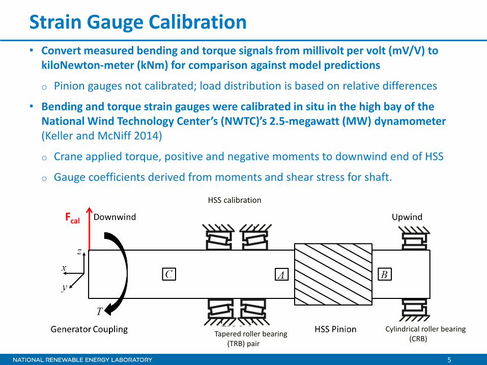
Strain Gauge Calibration • Convert measured bending and torque signals from millivolt per volt (mV/V) to
kiloNewton-meter (kNm) for comparison against model predictions
o Pinion gauges not calibrated; load distribution is based on relative differences
• Bending and torque strain gauges were calibrated in situ in the high bay of the National Wind Technology Center’s (NWTC)’s 2.5-megawatt (MW) dynamometer (Keller and McNiff 2014)
o Crane applied torque, positive and negative moments to downwind end of HSS
o Gauge coefficients derived from moments and shear stress for shaft.
HSS calibration
Fcal
Cylindrical roller bearing (CRB) Tapered roller bearing
(TRB) pair

6
Dynamometer Testing
• The NWTC 2.5-MW dynamometer was used in Phase 3 testing • Load cases particularly of interest with respect to HSS stage
(Link et al. 2013) o Nontorque loads o Radial misalignment of high-speed shaft o Emergency shutdown
• Model/test validation with torque and nontorque loads (NTL)
• Dynamometer operated in torque control mode o Torque commanded and applied by the dynamometer at fixed speed o One second of 2,000 Hertz (Hz) data were recorded on the HSS.

7
3 10 15
Multibody Model in SIMPACK
GRC gearbox model in SIMPACK (Guo 2014) o HSS modeled as flexible three-dimensional
(3D) beam structure using node-based nonlinear finite difference approach
o Each beam element modeled as a cross section connected by nodes with six degrees of freedom (DOF)
o Bearings modeled as visco-elastic springs. Pinion modeled using force element FE-225
o Nodes 3, 10, and 15 provide orthogonal moments and torque.
Force element(FE)
SIMPACK model for HSS (Image courtesy of Latha Sethuraman)
Existing multibody model (Guo 2014)
SIMBEAM models for HSS in SIMPACK (Image courtesy of Latha Sethuraman)
CRB TRB-DW TRB-UW
To HSS-gear FFE-225
Upwind (UW) Downwind (DW)

8
Effect of Torque and Nontorque Loads on HSS Loads
• HSS loading behavior tested at five different power levels
o Generator offline (zero torque), 25%, 50%, 75%, and 100% rated torque.
• Combinations of torque and NTL (up to 300 kNm) were also examined to:
o Investigate the impact of thrust, pitch, and yaw on HSS loads.
o Examine behavior of generator coupling and how it affects the HSS loads.
o Isolate gearbox motion at different power levels and identify potential contributions to HSS misalignment.

9
Torque pulsations observed at all power levels–10%/rev Prof. Don Houser (Ohio State University) has been investigating this phenomenon Tooth spacing errors in the HSS pinion could be a possible contributor to this variation.
• HSS torque
HSS Loads at Different Power Levels
10
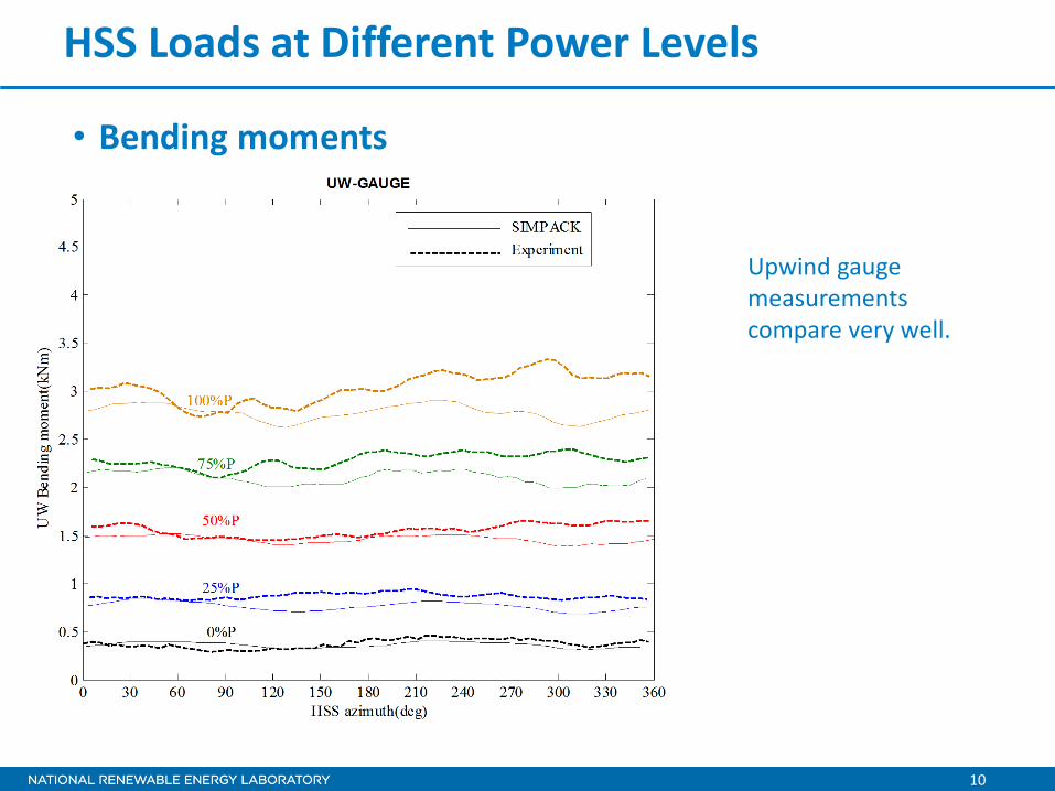
Upwind gauge measurements compare very well.
• Bending moments
HSS Loads at Different Power Levels

11
SIMPACK: twice per rotor revolution frequency content becomes more prominent at higher power.
• Bending moments
HSS Loads at Different Power Levels

12
SIMPACK: relatively constant at 0.35 kNm. Experimental results: demonstrate variations.
• Bending moments
HSS Loads at Different Power Levels

13
Uncertainties in modeling: o Limited information on
stiffness for gearbox bushing and generator coupling (Zaidi and Crowther 2009, DNV GL 2013).
o Gearbox motion not observed.
o Experimental data showed coupling-induced harmonic content.
o Coupling assumed to behave as a linear spring.
o Validity of this assumption remains to be investigated.
HSS Loads at Different Power Levels
14
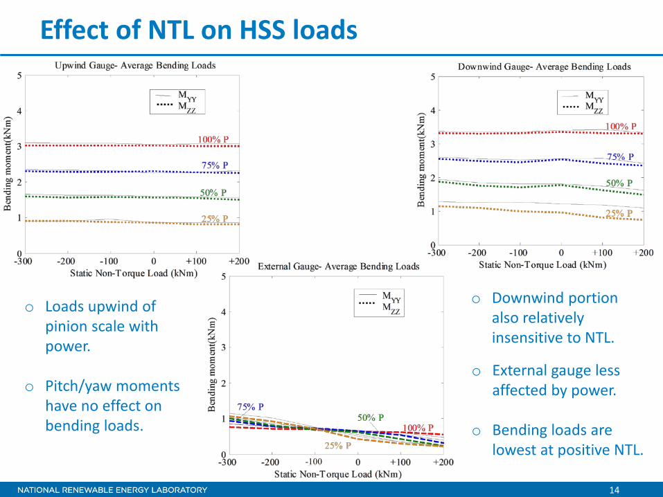
Effect of NTL on HSS loads
o Loads upwind of pinion scale with power.
o Pitch/yaw moments
have no effect on bending loads.
o Downwind portion also relatively insensitive to NTL.
o External gauge less affected by power.
o Bending loads are
lowest at positive NTL. -100

15
Effect of NTL on HSS loads
Inferences: o CRB and upwind TRB
are less likely to be influenced by NTL.
o Downwind TRB
expected to be influenced by coupling behavior.
-100

16
Effect of Misalignment on HSS Loads • Misalignment is a common problem in rotating machinery
o Computational studies by Whittle et al. 2011 have demonstrated the influence on bearing life
• In wind turbine gearboxes, misalignment is typically caused by: o Inaccurate assembly
o The relative position of components shifting after assembly
o Gearbox tilting or rocking, or bushing deflection
o Large torque or transient conditions
o Rubber that is sensitive to environmental conditions, creep, or fatigue
• Important: Can be pre-existing/dynamically induced (gearbox motion)
• IMPACT: Possible increase/decrease in shaft bending loads and therefore TRB loads.

17
Misalignment and Gearbox Motion
Types of misalignment
(Piotrowski 2006) Parallel Misalignment Angular Misalignment
“Mixed” Misalignment
(Piotrowski 2006)
(Piotrowski 2006)

18
Misalignment and Gearbox Motion Misalignment can be initiated by gearbox motion Rolling from low bushing stiffness in torsion Pitching from low bushing stiffness about Y
Sensors for gearbox motion --Trunnion Z_ Stbd, port: Displacements in Z --My_Trunnion_bottom: Gearbox tilt
Trunnion_Z_stbd
Trunnion_Z_port
My_Trunnion_bottom
Gearbox roll motion measurement (Image courtesy of Latha Sethuraman)
Gearbox Tilt measurement ( Image courtesy: Latha Sethuraman)

19
GEN
Gearbox Motion and Misalignment
GRC gearbox
L
GRC gearbox and generator (GEN) in aligned condition

20
Gearbox Motion and Misalignment
GEN φ
L
Photo by Jon Keller, NREL 32491
Misaligning the generator using shims

21
Gearbox Motion and Misalignment
β
GEN φ
∆θ=φ+β Upwind
β - Gearbox tilt angle Determined from proximity sensor
∆
= −
"3tan 1 xβ∆x
β
Gearbox tilting upwind

22
Gearbox Motion and Misalignment
GEN φ
∆θ =φ-β Downwind
β - Gearbox tilt angle Determined from proximity sensor
∆
= −
"3tan 1 xβ∆x
β
Gearbox tilting downwind

23
Gearbox Motion and Misalignment
GEN φ
φ ∆z (millimeters)
0 0
0.5o 5.5
1o 11
2o 22
30
33
Fz_SIMPACK
Myy_SIMPACK
Fz_SIMPACK = Kz L φ
Myy_SIMPACK = Kyy φ
L
∆x β
Misalignment test conditions and SIMPACK modeling
24
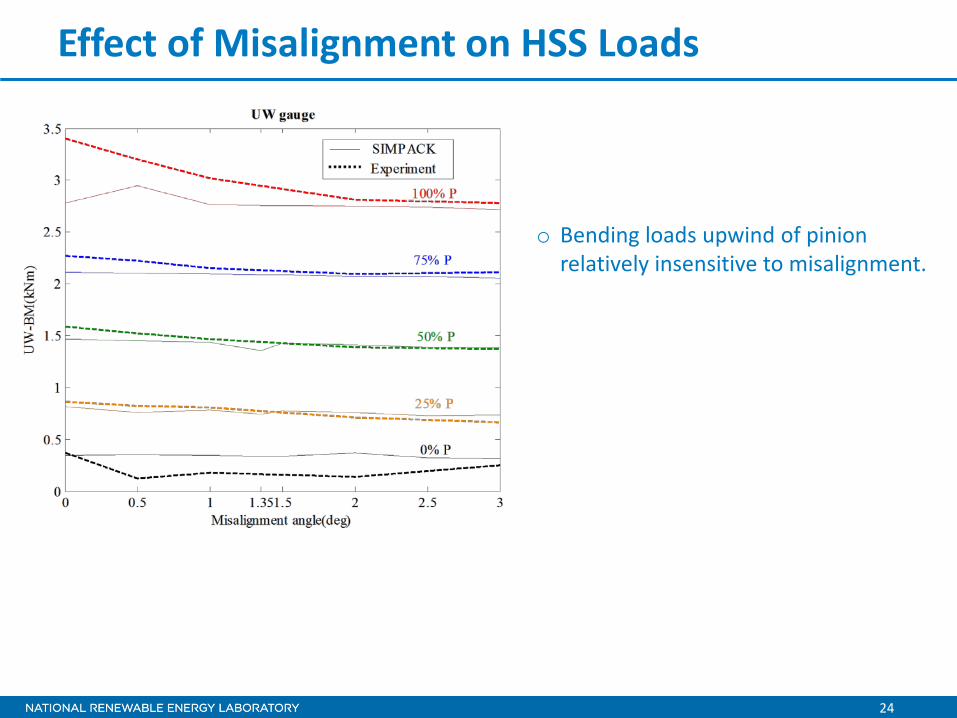
Effect of Misalignment on HSS Loads
o Bending loads upwind of pinion relatively insensitive to misalignment.

25
o Bending loads downwind of pinion: dips observed at 1.35o and 2o at 50% power.
Effect of Misalignment on HSS Loads

26
Effect of Misalignment on HSS Loads o SIMPACK simulations
predicted lowest loads at 1.35o
o Only five experimental data points: Difficult to locate the minima.
Could be the actual minima?

27
Effect of Misalignment on HSS Loads
Interpreting gearbox roll motion
o Gearbox bushings extremely stiff in radial direction
o Roll motion 0 o No influence on external gauge.

28
Effect of Misalignment on HSS Loads
o Average gearbox tilting, β up to 0.36o
o Influences loads on
external gauge
Interpreting gearbox tilt motion

29
Effect of Misalignment on HSS Loads
Gearbox tilting caused the valleys to shift to the left
Average gearbox tilting, β up to 0.36o

30
Conclusions
• Examined HSS torque and bending loads o Strain gauge measurements used to validate SIMPACK model
• Few major observations: o Shaft torque and bending compare well with SIMPACK model
– Measured shaft torque displayed + 10% variation per revolution
o HSS loads insensitive to NTL o Loads upwind and downwind of the HSS pinion linear with torque o Loads downwind of the TRB insensitive to torque, more sensitive
to generator alignment o Shaft misalignment reduced loads on downwind portion of HSS
– Relieved weight of brake disc – Reduction in downwind TRB loads
o Gearbox motion contributed to misalignment.

31
Further Work
• Conduct TRB load analysis from measurements
• Compare measurements with analytical tools and SIMPACK models for predicting bearing loads
• Examine additional test cases, such as impact events, including emergency shutdown
• Use INDIRECT approach as real-time bearing life assessment tool
• Assess bearing load zone distribution and contact stress
• Evaluate source of torque variation, generator coupling dynamics, and their influence on bearing load zone.

32
Acknowledgments This work was funded by the U.S. Department of Energy under Contract No. DE-AC36-08GO28308 with the National Renewable Energy Laboratory. Funding for the work was provided by the DOE Office of Energy Efficiency and Renewable Energy, Wind and Water Power Technologies Office. Contact information Latha Sethuraman Email: [email protected] Phone: 303-384-7481 Photo by HC Sorensen, Middelgrunden Wind Turbine Cooperative, NREL 17855
NWTC 2.5MW dynamometer
Photo by Mark McDade, NREL 32734

33
References • DNV GL (2013). NREL Gearbox Reliability Collaborative Coupling Stiffness Test Report. (internal only)
• Gearsolutions.com. (2010). "Troubleshooting Wind Gearbox Problems." Accessed March 25, 2015: http://www.gearsolutions.com/article/detail/5966/troubleshooting-wind-gearbox-problems-.
• Guo, Y.; Keller, J.; LaCava, W. (2014). “Planetary Gear Load Sharing of Wind Turbine Drivetrains Subjected to Non-Torque Loads.” Wind Energy, doi: 10.1002/we.1731.
• Horenbeek, A.V.; Ostaeyen, J.V.; Duflou, J.R.; Pintelon, L. (2013). "Quantifying the added value of an imperfectly performing condition monitoring system—Application to a wind turbine gearbox." Reliability Engineering & System Safety (111:2013); pp. 45-57.
• Keller, J.; McNiff, B. (2014). " Gearbox Reliability Collaborative High-Speed Shaft Calibration. " NREL/TP-5000-62373. Golden, CO: National Renewable Energy Laboratory.
• Link, H.; Keller, J.; Guo, Y.; McNiff, B. "Gearbox Reliability Collaborative Phase 3 Gearbox 2 Test Plan." NREL/TP-5000-58190. Golden, CO: National Renewable Energy Laboratory.
• Piotrowski, J.(2006). Shaft Alignment Handbook, Third Edition, CRC Press, 2006. • Sheng, S. (2013). "Report on Wind Turbine Subsystem Reliability - A Survey of Various Databases."
NREL /PR-5000-59111.
• Stadler, K.; Baum, J. (May 2014) ."Premature white etching crack bearing failures in wind gearboxes." Presented at the 2014 Society of Tribologists and Lubrication Engineers Annual Meeting & Exhibition.
• Whittle, W.; Shin, W.; Trevelyan, J.; Wu, J. (2011). "A Parametric Study of the Effect of Generator Misalignment on Bearing Fatigue Life in Wind Turbines." Presented at EWEA 2011.
• Zaidi, N.A.; Crowther, A. (2009). GRC Rubber mount testing for NREL. Romax Technology (internal only).