geared electric propulsion - newcastle university · john buckingham – geared electric propulsion...
TRANSCRIPT
John Buckingham – Geared Electric Propulsion
1
Geared Electric Propulsion
John Buckingham CEng FIMechE, MIMarEST
Chief Mechanical Engineer, BMT Defence Services Limited
The use of an electric machine with a gearbox is not a new phenomenon. They have been used to
provide a compact propulsion solution with motors which operate at standard industrial speeds.
When used in Z-drives they provide the same compact solution for an azimuthing drive with the
minimum size pod.
Usually asynchronous motors are used with variable speed drives and fixed pitch propellers to
provide high torque and thrust at a range of ship speeds without the fixed speed need for a
controllable pitch propeller (CPP) and the related need for propeller blade pitch angle control and the
hydraulic actuation that this requires. However modified geared electric and other similar solutions
are explored to assess their potential benefits for an 80m research vessel. A solution with two twin-
wound fixed-speed motors with CPP was explored to understand its potential benefits and to identify
any performance shortfalls it may present. The study considered the issues involved in the trade of
efficiencies between motor converters and the CPP losses at different blade angles. The study also
considers a range of sea states including the sensitivity of the combinator curve.
INTRODUCTION
For many years, electric motors have been used as Power Take-In (PTI) drives for
slow speed operations to avoid low engine loads and poor combustion in the
mechanical drive comprising the two or four stroke engines. For warships and
research ships, direct electric drive has also allowed for a quieter drive with no gear
noise and much reduced noise from the acoustically isolated DG sets.
As ships have grown in size and top speeds have increased, both to meet for
commercial pressures, the size, weight and cost of direct electric drive motors has
also grown. The size of electric motors is roughly proportional to their torque rating
and there is a challenge to fit ever increasing diameter motors in the fine after
hullforms for faster vessels. Although the motors can be moved forward to benefit
the longitudinal weight balance, this makes the propulsion system consume more
internal space which is less efficient in ship design and operating terms.
A large motor is made of copper (conductor), iron (flux connector) and steel (frame
and strength bearing members). The price of copper has fluctuated with the global
economy but there is a definite historical upward growth trend whereas the price of
iron ore has followed a falling trend.

John Buckingham – Geared Electric Propulsion
2
Figure 1. Iron Price since 2009 (Ref InfoMine.com (Ref 1) )
To address the cost and ship-fit implication of large slow-speed motors, geared
motors have been considered for some time, both as Z-drive prime movers and as
dives through a standard reduction gearbox to a conventional propeller arrangement.
Such a design allows standard marine motors to be employed, one or two into a
reduction gearbox.
GEARED-ELECTRIC
Maillardet (Ref 2) makes a strong case for the use of standard affordable medium
speed motors to drive propellers through reduction gears on the basis of acquisition
cost, size, weight. He addresses the reliability issues that are often associated with
gearboxes and observes that an electric motor-gearbox arrangement does not
require clutches, actuators and interlocks which are often the source of unreliability.
The use of gearboxes introduces tooth contact noise at a frequency which may
easily propagate through the propeller shaft to the propeller and provide a source of
underwater radiated noise. Although flexible shaft couplings can be used to manage
this, a noise-reduced gearbox probably would add to the acquisition costs contrary to
Maillardet’s counter claim.
Maillardet discusses the scope for the use of epicyclic gearboxes which offer a more
compact solution than parallel shaft designs. They also offer scope for greater
reduction ratios as per the cited application of steam turbine drive reduction in the
steam driven tankers. Epicyclic gearboxes were used for the steam turbine generator
to save space in the NS Savannah. Budd (Ref 3) describes how epicyclic gearboxes
(EGB) could be used for steam-driven contra-rotating propeller (CRP) applications.
However CRP and EGB are seldom used at sea due their considerable costs and
currently they would be used for specialist applications where space was at a
premium.
John Buckingham – Geared Electric Propulsion
3
PROPELLER SHAFT-MOUNTED MOTORS
For many years, propeller-shaft mounted electric machines have been used for
synchronous power generation. The two or four stroke engine runs at a steady
speed and the machine acts as a generator to supply electrical power at the required
frequency. With the introduction of variable ship speeds to meet commercial
pressures and the opportunity to use power electronics, the machine can now act at
any shaft speed as a generator and due to the four quadrant nature of the power
electronics, it is also feasible to use them as motors for slow speed manoeuvring in
areas where full thrust is not required. Companies such as GE, Rolls-Royce (Hybrid
Shaft Generator system (HSG)) (Refs 4 & 5) ), MAN and The Switch of Finland offer
such systems with The Switch offering P/M solutions.
More recently P/M machines have been used instead of conventional motors and a
more comprehensive explanation of the benefits is provided at Ref 6.
GEARED ELECTRIC NAVAL SHIPS
Geared electric propulsion is employed in the French FREMM class warship, the
German F125 frigate and the UK MARS tanker.
French FREMM
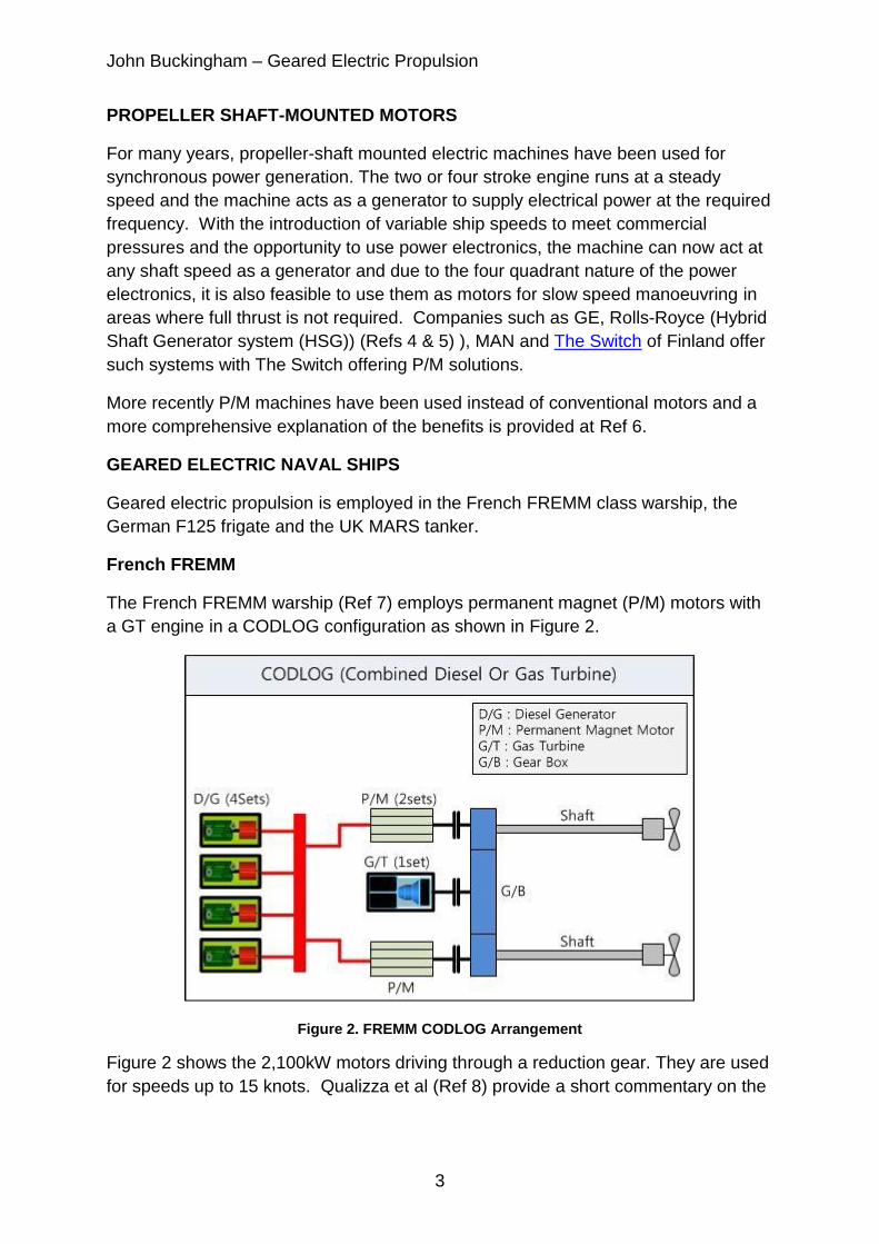
The French FREMM warship (Ref 7) employs permanent magnet (P/M) motors with
a GT engine in a CODLOG configuration as shown in Figure 2.
Figure 2. FREMM CODLOG Arrangement
Figure 2 shows the 2,100kW motors driving through a reduction gear. They are used
for speeds up to 15 knots. Qualizza et al (Ref 8) provide a short commentary on the
John Buckingham – Geared Electric Propulsion
4
design intent of the FREMM including an explanation of the nominal operating
modes or configurations of the CODLAG-come-hybrid propulsion system.
For medium speed designs, i.e. 1,000rpm to 10,000rpm P/M motors offer significant
benefits over standard AC squirrel cage asynchronous and synchronous motors. In
general they have twice the torque density leading to designs which are half the size
and weight, (Ref 2).
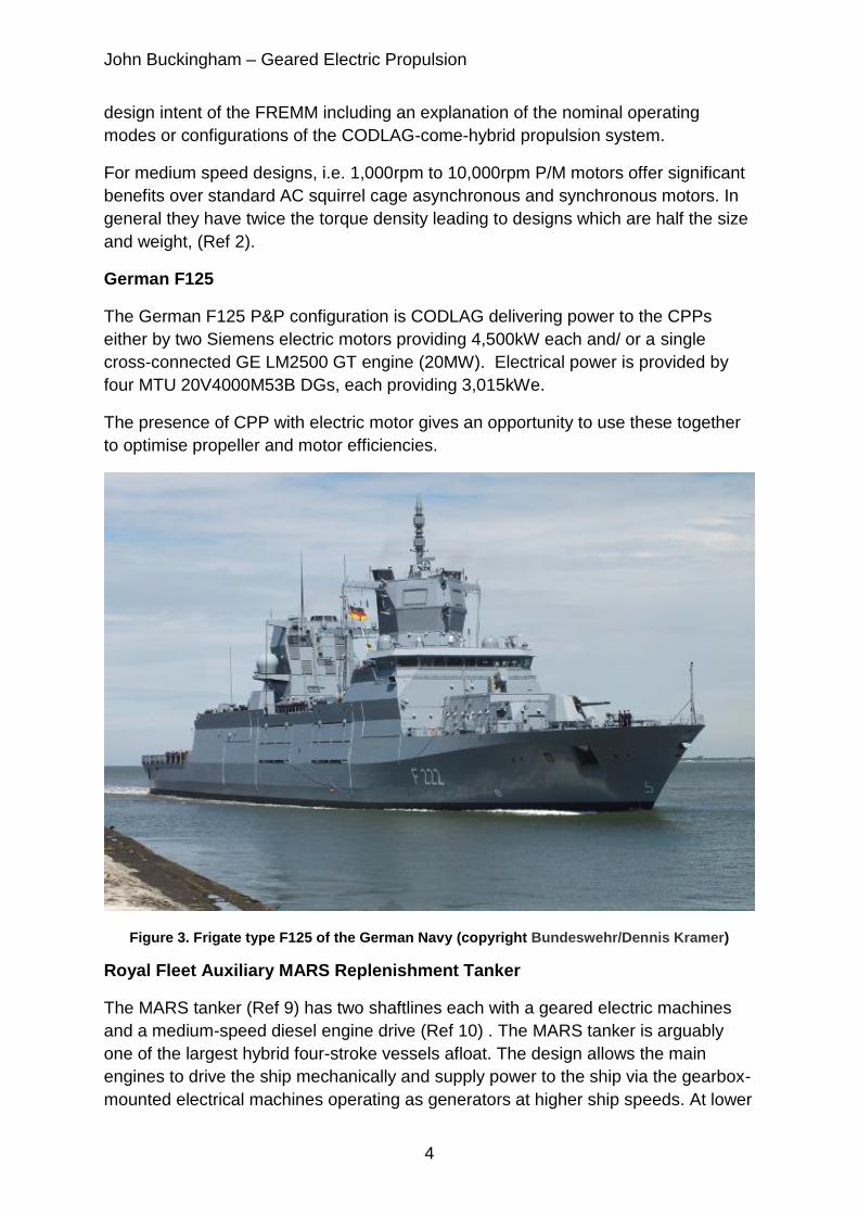
German F125
The German F125 P&P configuration is CODLAG delivering power to the CPPs
either by two Siemens electric motors providing 4,500kW each and/ or a single
cross-connected GE LM2500 GT engine (20MW). Electrical power is provided by
four MTU 20V4000M53B DGs, each providing 3,015kWe.
The presence of CPP with electric motor gives an opportunity to use these together
to optimise propeller and motor efficiencies.
Figure 3. Frigate type F125 of the German Navy (copyright Bundeswehr/Dennis Kramer)
Royal Fleet Auxiliary MARS Replenishment Tanker
The MARS tanker (Ref 9) has two shaftlines each with a geared electric machines
and a medium-speed diesel engine drive (Ref 10) . The MARS tanker is arguably
one of the largest hybrid four-stroke vessels afloat. The design allows the main
engines to drive the ship mechanically and supply power to the ship via the gearbox-
mounted electrical machines operating as generators at higher ship speeds. At lower
John Buckingham – Geared Electric Propulsion
5
ship speeds, the DG sets supply power to the ship and drive the ship via the motors,
(Ref 11) .
RENK AED
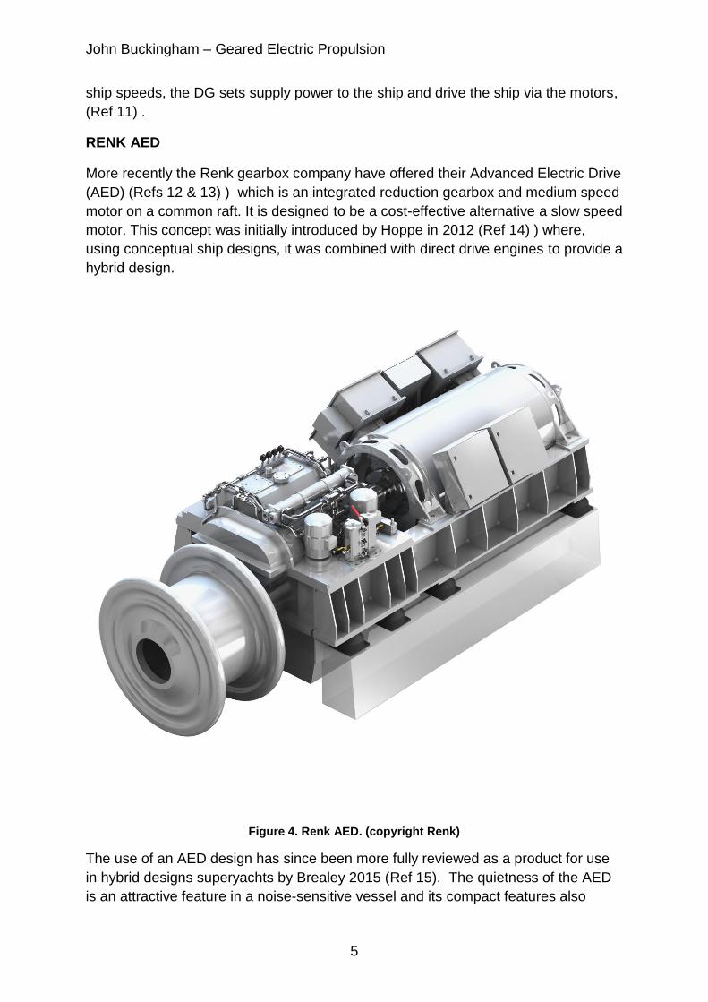
More recently the Renk gearbox company have offered their Advanced Electric Drive
(AED) (Refs 12 & 13) ) which is an integrated reduction gearbox and medium speed
motor on a common raft. It is designed to be a cost-effective alternative a slow speed
motor. This concept was initially introduced by Hoppe in 2012 (Ref 14) ) where,
using conceptual ship designs, it was combined with direct drive engines to provide a
hybrid design.
Figure 4. Renk AED. (copyright Renk)
The use of an AED design has since been more fully reviewed as a product for use
in hybrid designs superyachts by Brealey 2015 (Ref 15). The quietness of the AED
is an attractive feature in a noise-sensitive vessel and its compact features also
John Buckingham – Geared Electric Propulsion
6
enable it to be installed in the limited space set aside for main machinery. The
speed control of the AED employs PWM converters which take the ships main
switchboard frequency and voltage and modify it to suit the requirements for the
motor’s speed and torque output. Typically these are silicon –based thyristor devices
which take the rectifier supply and use high frequency switching methods to
manufacture the required motor supply. Such switching leads to losses which
manifest themselves as heat which lowers the efficiency of the conversion process
and requires the provision of cooling systems.
MECHANICAL-ELECTRICAL HYBRIDS
One of the most notable earliest mechanical-electrical hybrids is the Type 23 frigate
(Ref 16). designed in the 1970’s, it employs propeller shaft-mounted dc motors with
a GT engine drive through a reduction gearbox (Ref 17). At speeds between 15 and
22 knots or so the motors can operate with the GT engines to make the most of the
DG set fuel economy whilst the balance of the required propulsion power is taken
from the GT engines.
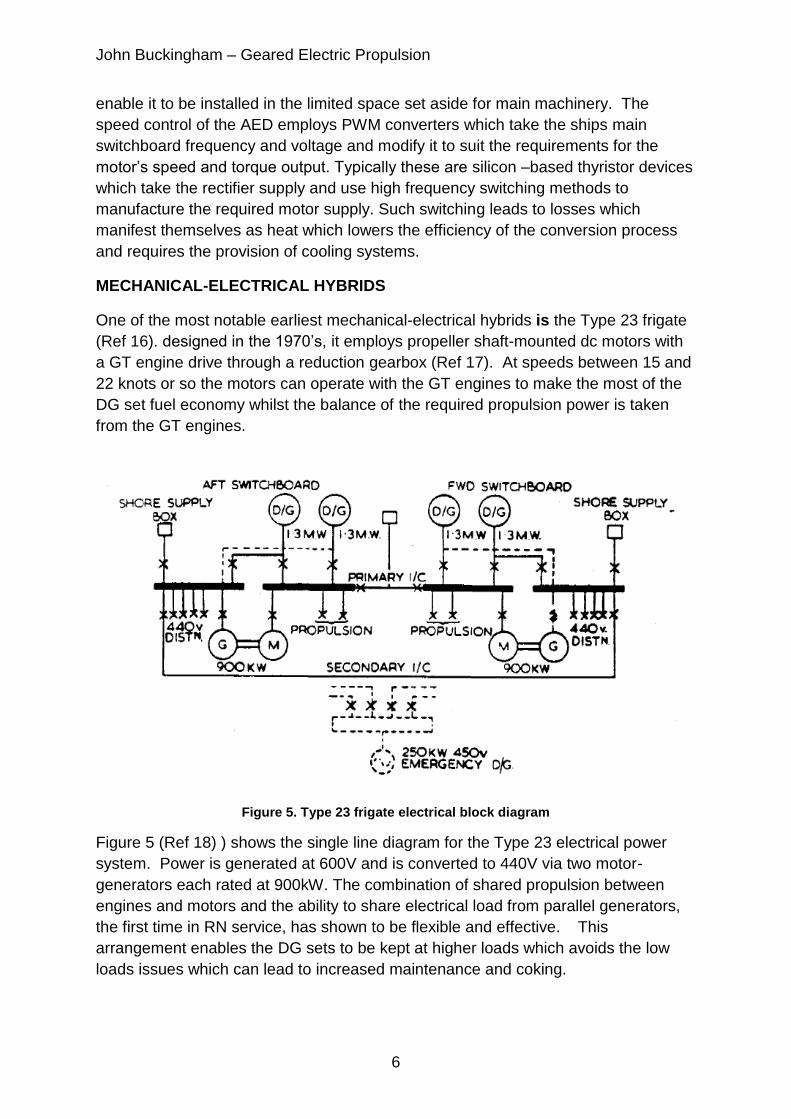
Figure 5. Type 23 frigate electrical block diagram
Figure 5 (Ref 18) ) shows the single line diagram for the Type 23 electrical power
system. Power is generated at 600V and is converted to 440V via two motor-
generators each rated at 900kW. The combination of shared propulsion between
engines and motors and the ability to share electrical load from parallel generators,
the first time in RN service, has shown to be flexible and effective. This
arrangement enables the DG sets to be kept at higher loads which avoids the low
loads issues which can lead to increased maintenance and coking.

John Buckingham – Geared Electric Propulsion
7
Figure 6. Type 23 Electrical Power Generation & Distribution
Figure 6 (Ref 19) shows the use of thyristor converters (ac/dc) to vary the supply
from the main switchboards to provide the required power and voltage to the motors
so that they turn at the required speed.
Dannatt ( Ref 20) further describes the electrical power and propulsion systems.
The three phase thyristor-converter provides a maximum dc output of 810V. Allowing
for losses this gives a usable 750V dc which is suitable for the design of dc motor
employed. The protection of the Type 23 electrical system is described in more
detail by Scott ( Ref 21) .
Although modern motor control systems employ different switching strategies and
make use of more modern solid-state switching technologies, they still represent an
energy transformation where there are losses and thus a reduction in the overall
propulsion efficiency.
TWIN-WOUND MOTORS
To address the losses with converters, the Norwegian company, Stadt (Ref 22)
introduced geared electric motors which were twin-wound such that the motor has
two sets of windings. A supply to one winding with a given number of pole pairs
provides one synchronous speed, which the supply of power to the other winding
gives a different synchronous speed. Such a design in essence has a simple make-
break switch isolator between the switchboard and the selected motor windings with

John Buckingham – Geared Electric Propulsion
8
a sinusoidal waveform power supply with no losses associated with the PWM
rectifier-converter (Ref 23) .
However such a design would mean that the ship could only operate at one of two
speeds in a given speed-resistance situation, where that is defined by displacement,
sea state and hullform fouling amongst other possible factors. To achieve variable
thrust and thus variable speed, a controllable pitch propeller (CPP) is used. By
varying the propeller blade pitch angle for a given shaft speed, a range of thrust and
thus ship speeds can be achieved. Thus the losses are “transferred” from the PWM
to the CPP with the additional efficiency loss between CPP and fixed pitch propeller
(FPP) which is assumed to be 1% across the whole pitch range.
SANCO STAR
The Stadt propulsion system was initially applied to the research ship the Sanco
Star, one of a series of research vessels which are still employed for underwater
seismic exploration in the oil and gas industry.
Figure 7. Sanco Star – copyright Sanco Shipping AS
The Sanco Star has the following principal characteristics.
Parameter Value
Length 80m
Beam 16m
Draught (transit) 6m
Maximum contracted speed 14+ knots
John Buckingham – Geared Electric Propulsion
9
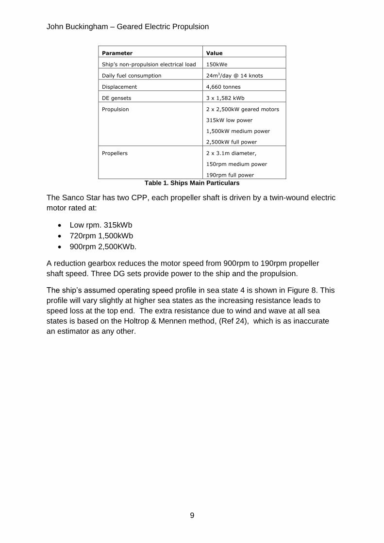
Parameter Value
Ship’s non-propulsion electrical load 150kWe
Daily fuel consumption 24m3/day @ 14 knots
Displacement 4,660 tonnes
DE gensets 3 x 1,582 kWb
Propulsion 2 x 2,500kW geared motors
315kW low power
1,500kW medium power
2,500kW full power
Propellers 2 x 3.1m diameter,
150rpm medium power
190rpm full power
Table 1. Ships Main Particulars
The Sanco Star has two CPP, each propeller shaft is driven by a twin-wound electric
motor rated at:
Low rpm. 315kWb
720rpm 1,500kWb
900rpm 2,500KWb.
A reduction gearbox reduces the motor speed from 900rpm to 190rpm propeller
shaft speed. Three DG sets provide power to the ship and the propulsion.
The ship’s assumed operating speed profile in sea state 4 is shown in Figure 8. This
profile will vary slightly at higher sea states as the increasing resistance leads to
speed loss at the top end. The extra resistance due to wind and wave at all sea
states is based on the Holtrop & Mennen method, (Ref 24), which is as inaccurate
an estimator as any other.
John Buckingham – Geared Electric Propulsion
10
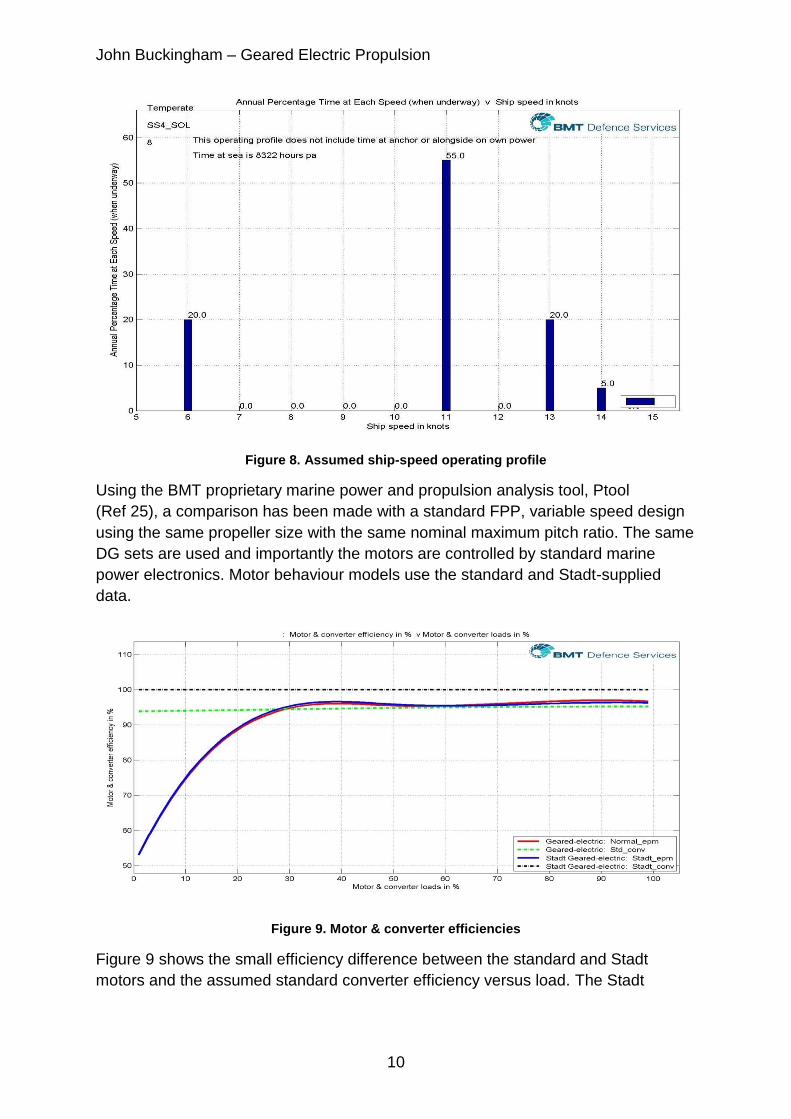
Figure 8. Assumed ship-speed operating profile
Using the BMT proprietary marine power and propulsion analysis tool, Ptool
(Ref 25), a comparison has been made with a standard FPP, variable speed design
using the same propeller size with the same nominal maximum pitch ratio. The same
DG sets are used and importantly the motors are controlled by standard marine
power electronics. Motor behaviour models use the standard and Stadt-supplied
data.
Figure 9. Motor & converter efficiencies
Figure 9 shows the small efficiency difference between the standard and Stadt
motors and the assumed standard converter efficiency versus load. The Stadt
John Buckingham – Geared Electric Propulsion
11
converter is 100% efficient as there is no power conversion equipment (Ref 26) . The
analysis uses a fixed value gearbox efficiency for the assessment of both designs.
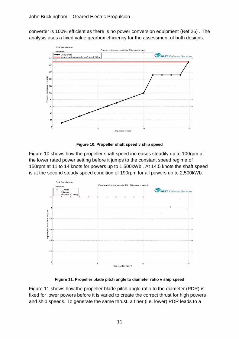
Figure 10. Propeller shaft speed v ship speed
Figure 10 shows how the propeller shaft speed increases steadily up to 100rpm at
the lower rated power setting before it jumps to the constant speed regime of
150rpm at 11 to 14 knots for powers up to 1,500kWb . At 14.5 knots the shaft speed
is at the second steady speed condition of 190rpm for all powers up to 2,500kWb.
Figure 11. Propeller blade pitch angle to diameter ratio v ship speed
Figure 11 shows how the propeller blade pitch angle ratio to the diameter (PDR) is
fixed for lower powers before it is varied to create the correct thrust for high powers
and ship speeds. To generate the same thrust, a finer (i.e. lower) PDR leads to a
John Buckingham – Geared Electric Propulsion
12
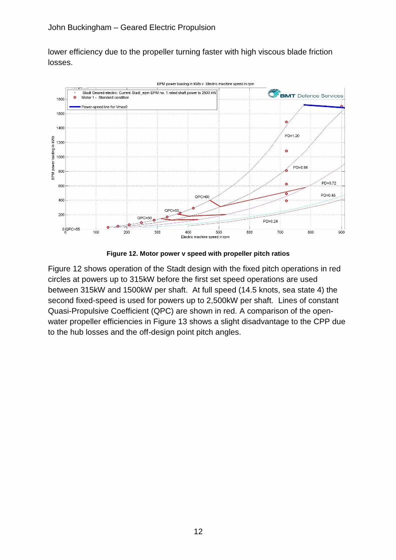
lower efficiency due to the propeller turning faster with high viscous blade friction
losses.
Figure 12. Motor power v speed with propeller pitch ratios
Figure 12 shows operation of the Stadt design with the fixed pitch operations in red
circles at powers up to 315kW before the first set speed operations are used
between 315kW and 1500kW per shaft. At full speed (14.5 knots, sea state 4) the
second fixed-speed is used for powers up to 2,500kW per shaft. Lines of constant
Quasi-Propulsive Coefficient (QPC) are shown in red. A comparison of the open-
water propeller efficiencies in Figure 13 shows a slight disadvantage to the CPP due
to the hub losses and the off-design point pitch angles.
John Buckingham – Geared Electric Propulsion
13
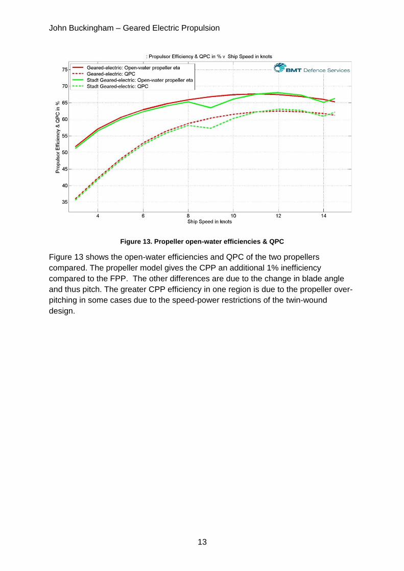
Figure 13. Propeller open-water efficiencies & QPC
Figure 13 shows the open-water efficiencies and QPC of the two propellers
compared. The propeller model gives the CPP an additional 1% inefficiency
compared to the FPP. The other differences are due to the change in blade angle
and thus pitch. The greater CPP efficiency in one region is due to the propeller over-
pitching in some cases due to the speed-power restrictions of the twin-wound
design.

John Buckingham – Geared Electric Propulsion
14
Figure 14. DG Set loading
Figure 14 shows how the DG sets in the Stadt design have a lower loading due to
the absence of converter losses. This leads to a lower fuel consumption rate as
shown in Figure 15.
Figure 15. Fuel Consumption Rates
Figure 15 shows how the twin-winding design offers a lower fuel consumption
across the speed range for this sea state. For the given operating his leads to a 5%
John Buckingham – Geared Electric Propulsion
15
annual fuel saving. When the whole set of sea states are considered on a weighted
total, the savings are over 4% with there being a saving of over 3% at each sea
state.
CONCLUSIONS
This study has explored the use of geared electric propulsion and specifically has
assessed the use of twin-wound motors with CPP versus the use of the standard
motor-converter solutions with FPP employed in most such applications. The study
on one ship that actually operates at sea indicates that the losses due to CPP pitch
angle changes are not greater than the savings due to the omission of the need for a
converter.
The use of a twin-wound motor drive with thrust control via CPP, reduces the need
for electrical power transformation equipment and offers a potentially cheaper design
solution with an indication that fuel consumption is either better or no worse.
ACKNOWLEDGEMENTS
The active co-operation of the Norwegian company, Stadt AS is acknowledged with
thanks.
It is BMT’s intention to claim copyright for this work. The kind permission and
resources granted to the author by BMT are acknowledged with thanks.
All findings, ideas, opinions and errors herein are those of the author and are not
necessarily those of BMT Defence Services Limited or Stadt AS.
REFERENCES
1 http://www.infomine.com/investment/metal-prices/iron-ore-fines/all/ 2 Maillardet, P & Hoffman, D. “The geared medium speed induction motor”. JNE 39(2) 2000.
3 Budd, W I H. “Main reduction gears for contrarotation”. SNAME Dec 1968 & Marine
Technology. Pg 440. October 1969 4 O’Connor, M. “Propulsion system options for a modern multi-role patrol vessel’. INEC 2012.
5 Partridge, R. “Optimisation of power and propulsion for underway replenishment vessels”.
INEC 2012. 6 http://theswitch.com/2014/02/23/permanent-magnet-direct-drive-shaft-generators-in-marine-
applications/ 7 Hartmut Manseck. "Special Ship: The FREMM Frigates". Naval Forces magazine 2009
8 A. Qualizza, T. Perini, S. Michetti, G. Sulligoi, and S. Castellan, “Integrated Power Systems in
Cruise ships and Naval Vessels" Electric Ship Design Symposium, 2009. 9 BMT Defence Services Limited. Royal Fleet Auxiliary MARS tanker Design.
10 Couch, T & Fisher, J. “Power & propulsion: Meeting the Concept”. INEC 2016. April 2016.
Bristol, UK. 11
Buckingham, J E. “”Hybrid drives for naval auxiliary vessels” 2013 12
Hoppe. F. “RENK AED© Advanced Electric Drive. The ultimate propulsion for quiet ships”. 2014 [On Renk.biz website]
13 Hoppe, Franz; Herdt, Waldemar: Advanced Propulsion Gears for Super and Mega Yachts.
Proceeding Conference RINA, Genova, May 2011.

John Buckingham – Geared Electric Propulsion
16
14 Hoppe. “Hybrid propulsion combining gears and systems for naval vessels”. INEC 2012. 15
Brealey et al “Advanced Propulsion Trains for superyachts” 16
Hawke M B et al. "The Type 23 Frigate". 17
Cooper. B. C. "The Type 23 Boost Propulsion Gearbox". J.N.E., Vol. 29, No. 3 18
Thomas, T. “The Type 23 Duke Class Frigate”. RINA 1991. 19
Blackman, R, S “Type 23 – The Engineering Development”. JNE Vol 28 No 1. 20
Dannatt “The Type 23 Main electrical power and propulsion systems”. JNE Volume 33(1). 1991.
21 Scott “Electrical protection for the Type 23 frigate electrical 600V power system”. JNE Volume
29. Number 2 22
Stadt AS. Norwegian Electrical engineering company 23
“Motor drives from Stadt”. Marine Engineers’ Review (MER). November 2009., pg 16. 24
Holtrop, J & Mennen, GGJ. “An Approximate power prediction method“. Netherlands Ship Model Basin (MARIN). Wageningen, The Netherlands
25 “Ptool: Fast performance and cost modelling of propulsion powering systems”, J. E.
Buckingham. AES 2000, Paris. October 2000. 26
Stadt document – “The guideline to electric propulsion”. Accessed October 2016