gec hirst research centre ipsd memo no. 38krste/papers/padmavati...gec hirst research centre ipsd...
TRANSCRIPT

GEC HIRST RESEARCH CENTRE IPSD Memo No. 38
EAST LANE WEMBLEY Date: 14 February 1989
MIDDLESEX HA9 7PP Author: K Asanovic
Group Leader: B L R Cameron
Issuing Authority: P R Watkins
_I_n_f_o_r_m_a_t_i_o_n__P_r_o_c_e_s_s_i_n_g__S_y_s_t_e_m_s__D_i_v_i_s_i_o_n
_S_y_m_b_o_l_i_c__P_r_o_c_e_s_s_i_n_g__S_y_s_t_e_m_s__G_r_o_u_p
_P_a_r_a_l_l_e_l_i_s_i_n_g__S_p_e_e_c_h__R_e_c_o_g_n_i_t_i_o_n__A_l_g_o_r_i_t_h_m_s
_A_b_s_t_r_a_c_t
A variety of current speech algorithms are discussed and shown to exhibitmuch potential for parallel execution. The different processing require−ments of recognition and training are shown to map efficiently onto SIMD andMIMD architectures respectively. The PADMAVATI architecture under develop−ment in IPSD supports both forms of parallelism. An associative dialect of"C" is presented and used to implement a One Pass connected speech recogni−tion algorithm using the PADMAVATI content addressable memory (CAM). Per−formance estimates show that this algorithm will run faster than real timeon the PADMAVATI architecture. A scheme is presented to perform trainingand recognition runs in parallel on PADMAVATI using the farm paradigm. Thescheme requires only a minimal software investment yet should yield a near−linear speed−up with increasing numbers of processor nodes.
_C_i_r_c_u_l_a_t_i_o_n
Abstract only: Dr W S Bardo ) GEC−Marconi Ltd, Stanmore
Mr D G Barlow )Dr B J Isherwood )Mr D L Lewis ) Hirst Research CentreDr E Read )Dr D G Scotter )Dr I R Young )Dr M A El Fatatry )
MRC Library ) Marconi Research Centre, Baddow
ERC Library ) Engineering Research Centre, Stafford
Full copy: Mr B Nicholas ) Marconi Speech Systems, PortsmouthDr D Lindsay )
Dr S L Cundy )Dr J M Robinson )Mr P R Watkins )Dr J R M Mason )Mr B L R Cameron )Mr D J B Pearce ) Hirst Research CentreMr P B Dytrych )Mrs L C Wood )Mr K Frimpong−Ansah )Mr N G Dixon )Miss W J Holmes )Mr D B Howe )Dr G L Burn )Dr D Lester )Mr J D Robson ) Hirst Research CentreMiss K L Griffiths )Mr K Asanovic )Mr H Kingdon )
c 1989 The General Electric Company plc

Parallelising Speech Recognition AlgorithmsReport On Meetings Held 23, 25 November 1988
Present: B.L.R. CameronD.J.P. Pearce (1st meeting)L.C. WoodD.B. HoweJ.D. RobsonK.L. Griffiths (1st meeting)K. Asanovic
_I_n_t_r_o_d_u_c_t_i_o_n
These meetings were held to consider the potential for using parallel archi−tectures to accelerate speech algorithm execution. This report is struc−tured in three sections. The first section reviews current speech recogni−tion algorithms as presented by LCW. The second section outlines currentlyavailable parallel systems, and describes the PADMAVATI architecture underconstruction within IPSD. The final section discusses how speech algorithmscould be executed on parallel systems, with particular reference to the PAD−MAVATI architecture.
1. _S_p_e_e_c_h__A_l_g_o_r_i_t_h_m_s
All those considered had two phases, namely training and recognition. Dur−ing training a set of reference models is constructed from a set of trainingutterances. We may choose to model whole words or smaller sub−word units.In the recognition phase an unknown input utterance is compared against thereference models. Where the input is constrained to be a single word, andwhere our reference models are also single words, we can select the refer−ence which best matched the entire input utterance as our recognised word.In other cases we need to select the best sequence of reference models asour recognised word or sentence.
The following sections discuss the various models used, their training algo−rithms, and the corresponding recognition algorithms.
_R_e_f_e_r_e_n_c_e__T_e_m_p_l_a_t_e_s
One approach to modelling a reference speech pattern is to use a templateconsisting of a time sequence of frames. Each frame is a vector of parame−ters which characterise a short section of speech (~10−20 ms duration). Thereference templates are trained by some form of averaging over a set oftraining utterances.
January 26, 1989

− 2 −
_T_e_m_p_l_a_t_e__R_e_c_o_g_n_i_t_i_o_n__W_i_t_h__D_y_n_a_m_i_c__T_i_m_e__W_a_r_p_i_n_g__(_D_T_W_)
DTW is a method used to recognise reference templates. Here we consider thesimplest case; recognising an isolated word with whole word reference tem−plates. First we introduce some notation (taken from [1]).
We label frames in the input sequence, i = 1, 2,..., N; where N is the totalnumber of frames in the input sequence. Note i is also a time reference.We have K reference templates, labelled k = 1,2,...,K; and each template hasJ(k) frames, labelled j = 1, 2,..., J(k). We assume that we can calculate aframe distance measure d(i, j, k) to quantify the disparity between frame iof the input and frame j of the kth reference template. One possibility isa Euclidean distance between the parameter vectors. The kth plane of D(i,j, k) holds the cumulative distance measures for every reference template k.The cumulative distance measures represent the sum of d(i, j, k) along theminimum distance path from grid point (0, 0) to (i, j).
The algorithm is given in figure 1.
/* Initialise sentinels. */
for k = 1 .. ND(0, −1, k) = 0for j = 0 .. J(k)
D(0, j, k) = infinity
for i = 1 .. N /* loop on test frames */for k = 1 .. K /* loop on reference templates */
for j = 1 .. J(k) /* loop on frames in reference templates */D_prev = min { D(i−1, j−a, k) : 0 <= a <= 2 }D(i, j, k) = D_prev + d(i, j, k)
recognised = k : D(N, J(k), k) = min { D(N, J(t), t) : t = 1..K }
Figure 1 − DTW Isolated Word Recognition Algorithm
Note that we only allow the previous path to come from either the sameframe, the preceding frame, or the previous frame but one (a = 0, 1, 2,respectively). One extension of the above technique is to give each alter−native (a = 0, 1, 2) a probability weighting, which may be constant or mayvary with i and j.
_H_i_d_d_e_n__M_a_r_k_o_v__M_o_d_e_l_s__(_H_M_M_s_)
HMMs aim to provide superior recognition by modelling each reference unit asa number of states and a state transition matrix. Each state has an outputframe which is modelled probabilistically either with a discrete or continu−ous distribution. This uncertainty associated with a state output veils theidentity of the generating state, hence the adjective ’hidden’. The entriesin the state transition matrix are the probabilities of a transition fromone state to another in the reference unit. Transitions are usually con−strained to be either a loop to the current state, a jump to the next stateor a jump to the next state but one. These constraints are expressed as
January 26, 1989

− 3 −
zero probabilities in the state transition matrix for inadmissable statetransitions.
_H_M_M__R_e_c_o_g_n_i_t_i_o_n
The scheme is similar to DTW, but now the reference frames are the outputsof the HMM states. The HMM states are modelled probabilistically and so weneed a statistical distance measure, such as a multi−variate guassian dis−tance metric.
When searching the grid the possible paths are weighted with the transitionprobabilities between reference states.
_H_M_M__T_r_a_i_n_i_n_g
To train the HMMs, initial values are assigned to the model parameters andthen these are improved by an iterative estimation technique. Two grids ofpath distance measures are calculated for each word repetition in the train−ing set against the current model. One is calculated moving forward acrossthe grid, the other is calculated moving backwards. A weighted sum over thegrids for all word repetitions is then used to re−estimate the model parame−ters. The model can be improved by repeating the process with the updatedmodel parameters. It is possible to derive a distortion measure which indi−cates the probability of the new model generating the training set, and thiscan be used to control the number of iterations attempted.
_C_o_n_n_e_c_t_e_d__W_o_r_d__M_o_d_e_l_s
In general we would like to recognise connected speech. It is possible touse word models trained from isolated words to recognise connected speechbut in practice recognition performance is poor. Speakers run wordstogether and this gives rise to co−articulation effects at word boundaries.Improved performance can be obtained by training the word models with datataken from connected speech.
A problem here is the segmentation of a training utterance into it’s consti−tuent words. Manual segmentation is slow and error prone. One automaticsolution is to use an isolated word model to recognise word boundaries intraining utterances. These automatically extracted words can then be usedto train a connected word model. To refine the results we repeat the pro−cess but now using the new model to perform the word boundary recognition.The connected word models can then be used in one of the recognition schemesdescribed below.
_U_s_e__O_f__S_u_b_−_W_o_r_d__U_n_i_t_s
As vocabulary increases the number of models in a whole−word recognitionsystem becomes unmanageable. Larger vocabularies can be accomodated byusing sub−word units which are combined to form whole words. Various sizesof sub−units have been tried including demi−syllables and phonemes.
As with connected words, problems arise when attempting to segment a train−ing database of connected utterances into sub−word units. Again, automaticroutines can be developed which split utterances into elements of the
January 26, 1989

− 4 −
desired size.
_C_o_n_n_e_c_t_e_d__S_p_e_e_c_h__R_e_c_o_g_n_i_t_i_o_n
Usually we are interested in complete utterances, but connected methods alsoapply to the recognition of isolated words using sub−word units. With iso−lated word recognition we knew that each model had to start (end) at thebeginning (end) of the input utterance, and that a single model would matchthe whole utterance. With connected recognition a model can start or end atany point in the input. Connected recognition schemes may attempt to findthe optimal sequence of recognised units in terms of minimum cumulative dis−tance. Alternatively, the connected speech recogniser could be used to sec−tion the input into recognised units rated with a confidence score, and del−imited by start and end times. This will then provide the input to a moreintelligent system which may use syntactic, semantic and pragmatic knowledgeto provide more robust speech recognition or speech understanding.
Below we examine three classes of connected recognisers; one−pass, two−level, and level−building.
_O_n_e__P_a_s_s
The One Pass algorithm combines the reference unit matching and sequencingoperations by extending the above DTW scheme to allow between−template tran−sitions at template boundaries. For every input frame, i, we search for thetemplate end−frame, j = J(k), which has the lowest cumulative distance scoreand store the corresponding template number in an array T(i). When we tryto find a path to a start−frame, j = 1, we also consider the best end−framein the preceding time slot. We need to store back pointers to allow therecognised sequence to be recovered at the end of the utterance, array B(i,j, k) holds the time index of the end frame of the previous matched unit inthe current path. Note T(B(i, j, k)) gives the preceding template number.We use a further array, F(i), to store the back pointers for the templatenumbers in T(i). The algorithm is given in figure 2.
The One Pass algorithm is very efficient at finding the optimal sequence ofunits, but many good sub−optimal choices may be discarded early in thesearch.
January 26, 1989

− 5 −
/* Initialise sentinels. */
T(0) = 1for k = 1 .. K
D(0, 0, k) = infinity, B(0, 0, k) = 0D(0, 1, k) = 0, B(0, 1, k) = 0for j = 2 .. J(k)
D(0, j, k) = infinity, B(0, j, k) = 0
for i = 1 .. N /* loop on test frames */for k = 1 .. K /* loop on reference templates */
/* Between−template transition rules. */
if (D(i−1, 1, k) > D(i−1, J(T(i−1)), T(i−1)))D(i, 1, k) = d(i, 1, k) + D(i−1, J(T(i−1)), T(i−1))B(i, 1, k) = i−1
elseD(i, 1, k) = d(i, 1, k) + D(i−1, 1, k)B(i, 1, k) = B(i−1, 1, k)
/* Intra−template transition rules. */
for j = 2 .. J(k)j* = j’ : D(i−1, j’, k) = min { D(i−1, j−a, k) : 0<= a <=2 }D(i, j, k) = d(i, 1, k) + D(i−1, j*, k)B(i, j, k) = B(i, j*, k)
T(i) = t : D(i, J(t), t) = min { D(i, J(a), a) : a = 1 .. K }F(i) = B(i, J(T(i)), T(i))
recognised sequence is obtained by;
r = N, R = 0 /* R is number of recognised units. */while F(r) <> 0
push T(r) /* Use a stack as we recover last unit first. */r = F(r) /* Follow back pointer. */R = R + 1 /* Increment number of units found. */
Sequence can now be pulled off the stack.
Figure 2 − One Pass Connected Recognition Algorithm
_T_w_o__L_e_v_e_l
The Two Level process is the most comprehensive scheme. For every pair ofstart and end co−ordinates in the input utterance, b and e respectively (b <e), we obtain a cumulative distance between every reference and the sectionof the input starting at b and ending at e. We call this Do(b,e,k). Thenext step is to find the best distance for any given b and e. We call thisD*(b,e) where;
D*(b,e) = min { Do(b,e,k) : k = 1 .. K }
January 26, 1989

− 6 −
In the second stage the best p−sequence of units, with p = 1..L, has to befound. A p−sequence is a sequence of p reference units. If we let Dp*(p,e)be the best match for a p−sequence ending at e then,
Dp*(p, e) = min { D*(b, e) + Dp*(p−1, b−1) : 1 <= b <= e }
We can then find the optimum sequence length L*;
L* = L : Dp*(L, N) = min { Dp*(L’, N) : L’ = 1 .. N }
The Two Level algorithm has the advantage that as well as finding theoptimal sequence it is also possible to extract all the sub−optimalsequences. A major disadvantage of the Two Level algorithm is the largecomputational overhead.
_L_e_v_e_l__B_u_i_l_d_i_n_g
The Level Building algorithm is an attempt to reduce the computational com−plexity of the Two Level algorithm. Levels are labelled p = 1 .. L, where Lis the maximum number of levels. Each level corresponds to one recognisedunit in the input utterance. The best matched unit in level p ending atframe i is labelled U(p,i).
At the first level, LB finds the most likely reference unit U(1,i) startingat frame 1 and ending at frame i, for i = 1 .. N. It will become the firstunit in the decoded sequence if the first unit must end in frame i. At thesecond level, for every unit U(1,i’) and for every frame i, i > i’, the bestsecond unit U(2,i) is found. More generally, at each level p = 1 .. L, thebest p−sequence ending at time i is computed.
A disadvantage of the LB algorithm is that it is necessary to fix some max−imum value of L, the expected number of units in the input utterance.
2. _P_a_r_a_l_l_e_l__S_y_s_t_e_m_s
A convenient classification of hardware architectures is due to Flynn [2].
Conventional serial computers are classed as SISD (Single Instruction, Sin−gle Data) machines, where a single processor runs a program that manipulatesa single data stream.
A MIMD (Multiple Instruction, Multiple Data) machine can be seen as a col−lection of SISD processors. Each processor can run a separate program on aseparate data stream. A shared memory MIMD machine has a globally accesibleblock of memory which provides the communications medium between the multi−ple processors. A distributed memory MIMD architecture assigns a privateblock of memory to each processor, and processors communicate by messagepassing over some communications network. A transputer network is a distri−buted memory, MIMD machine with Inmos links providing communications betweenprocessing nodes.
January 26, 1989

− 7 −
MIMD machines are generally programmed in a task parallel manner where anumber of concurrent tasks co−operate to solve a problem. Many languagesfor MIMD machines are based on a conventional programming language withextensions to provide task creation, synchronisation, and message passing.Examples include Parallel C for the transputer, and Lucid Lisp for the IntelIPSC/2. Other languages were designed from the outset for parallel systems,such as Occam implemented on the transputer.
A further class of machines have a single central control unit which broad−casts instructions to a large collection of simple processing elements whichexecute commands in lockstep. These are termed SIMD (Single Instruction,Multiple Data) machines. Examples include the ICL DAP, GEC GRID, the Con−nection Machine, and the PADMAVATI CAM. Typically arithmetic is carried outbit−serially but word−parallel. Each arithmetic instruction may take a com−paratively long time to execute but the aggregate performance of the arrayis high. Also, for many applications only limited precision is required andthen execution can be accelerated further.
The final class in Flynn’s classification is MISD (Multiple Instruction,Single Data). Here a number of processors execute different instructions ona single data stream. Processing pipelines are a common example of thisarrangement which is analogous to a car production line. The degree ofparallelism is proportional to the number of stages in the pipeline, whichis limited by the number of clearly definable stages in the operation beingperformed. Floating point arithmetic is a popular candidate for MISD execu−tion, with the vector processing units of the Cray series being a primeexample.
Both SIMD and MISD machines exhibit data parallelism where the same opera−tion is performed on a large set of data. Vectorising FORTRAN compilershave been developed which can find the embedded data parallelism in existingFORTRAN code to exploit data parallel execution, though always with a lossin efficiency compared to special purpose code. Extensions to conventionallanguages have been devised to allow data parallel operations to be per−formed efficiently on both SIMD and MISD machines. Examples include theFORTRAN−8X standard, and CM−LISP for the Connection Machine.
_P_A_D_M_A_V_A_T_I
The PADMAVATI architecture has a hierarchy of hardware parallelism.
At the top level in the hierarchy, a Sun−3/260C acts as the host to a MIMDtransputer network. The target configuration has 16 transputer nodes, eachcontaining a T−800 transputer and 4−16 Mbytes of DRAM. Each transputer hasfour Inmos links providing high speed (20 Mbit/s) point to point communica−tion between processor nodes. The links can be reconfigured into any topol−ogy using a crossbar switching network controlled by the Sun.
A lower level of parallelism is provided by the content addressable memory(CAM) boards which can be attached to each transputer node via an expansionbus interface. Each CAM board provides over 8000 SIMD associative process−ing elements, and up to 16 boards can be added to a node. The transputeracts as a host to the CAM array broadcasting instructions and data throughcontrol locations memory mapped into the transputer’s address space. Each
January 26, 1989

− 8 −
CAM cell has 36 bits of storage, a flag bit, and logic to implement a smallbut highly orthogonal instruction set including search, read, and writeoperations. The cells are arranged in a linear array and each cell can readit’s neighbours flag bit to allow inter−cell communication. Arithmeticoperations are performed in a bit−serial, word−parallel manner using ascheme analogous to table look−up.
Within the PADMAVATI project Lisp and Prolog are being ported to the tran−sputer. These are being extended with message passing primitives andaccelerated by incorporating CAM into the language executor. In additionPADMAVATI is compatible with all standard transputer compilers, whichinclude most major programming languages such as C, FORTRAN, and PASCAL. Itis intended to support the use of CAM within these conventional languages byproviding function libraries.
3. _P_a_r_a_l_l_e_l_i_s_a_t_i_o_n__o_f__t_h_e__S_p_e_e_c_h__A_l_g_o_r_i_t_h_m_s
The speech algorithms exhibit much potential for concurrent execution.Recognition and training have different computational requirements and soare considered separately.
_R_e_c_o_g_n_i_t_i_o_n
We would like to speed the recognition process both to attain real timerecognition of continuous speech, and to reduce the time spent in developingnew recognition algorithms.
The Two Level and Level Building algorithms as given above require theentire utterance to be input before processing can be completed. However[1] presents left to right versions of the algorithms where processing canstep forward with each new input frame, ie. frame synchronously.
Much of the computation for each reference unit can be performed indepen−dently and hence concurrently. However it is necessary to broadcast eachframe of the input and to perform global arbitration amongst matching words.This becomes more of a problem in a connected speech recogniser where wordboundary information has to be collected and broadcast in every frame.
These communication overheads make the recognition process less amenable toparallel execution on loosely coupled systems such as distributed memoryMIMD architectures. Shared memory MIMD architectures could suffer from con−tention problems when processors attempt to read globally accesible loca−tions, but careful algorithm and system design could alleviate this. MISDpipelines can give a good but limited speed up for the arithmetic operationsinvolved in recognition, but cannot easily be used to speed up the decisionmaking and control processes.
SIMD architectures seem to match best the natural parallelism in the recog−nition process. SIMD machines support global broadcasting and decision mak−ing, and arithmetic can be performed efficiently in a data parallel manner.
Appendix A gives an algorithm for performing frame sychronous One Pass DTWconnected speech recognition using the PADMAVATI CAM. Although the CAM wasnot designed for numerical applications recognition performance is still
January 26, 1989

− 9 −
faster than real time. This is partly due to the rapid parallel write andglobal multiple response resolution typical of associative processors. Itshould be straightforward to extend this to a Level Building scheme as thiscan be viewed as several One Pass schemes operating in parallel [1].
A problem with SIMD is that it may involve significant effort to port anexisting sequential algorithm to a given processor array. This effort maybe justified when implementing a real time speech recogniser but not whenfirst developing and testing the recognition algorithms.
In general it is difficult to implement a sensible parallelisation schemefor an algorithm which is still under development using conventional impera−tive languages. However in a research environment we will often want toassess a recognisers performance with a large database of input utterances.Each recognition run is independent and so can proceed in parallel using thefarm paradigm described below for training.
_T_r_a_i_n_i_n_g
For speaker dependent systems training must be repeated for every new user,but for speaker independent systems this only has to be done once duringdevelopment. The execution time becomes more important in a researchenvironment where new models are developed and tested repeatedly.
The various forms of reference model have different training requirements.We consider here the training of connected unit HMMs with automatic segmen−tation of a training database as a complex and computationally demandingexample for parallelisation.
We first note that when training a set of models, each model is usuallytrained in isolation from the others. A natural scheme for parallelisationis therefore to split the training into separate tasks for each model. Astandard parallel programming paradigm which matches this form of taskparallelism is the "task farm". A farm contains a master process and anumber of identical worker processes. The master splits up the work intopackets then farms out the packets to the worker processes. Each workerreads in a work packet, performs the desired task on the data in the workpacket, then sends a result packet back to the master. For the trainingtask we can place the database of input utterances with the initial unitmodel into the work packet, and return the trained model in the resultpacket.
For each model, we can process each utterance in parallel; performing seg−mentation, grid calculations and part of the final summation over the gridindependently. We then combine the new partial sums to generate a newmodel, and iterate. Much of the processing within each utterance exhibitsdata parallelism, for example in the recognition process we repeat the localdistance calculation for many points on the grid.
Extensive parallelisation schemes can involve a large software investmentusing the currently available explicitly parallel programming languages, butany physical parallel architecture has only a finite degree of parallelism.It is therefore desirable to choose the simplest parallelisation schemewhich can efficiently utilise the physical parallelism of a given
January 26, 1989

− 10 −
architecture. We have noted that each reference unit can be trainedseparately in a processing farm. If the number of units to be trainedexceeds the number of processors available then we can guarantee full utili−sation of the available parallelism without having to write further algo−rithm specific code to extract the finer grain of parallelism within eachtraining task. Fortunately the processor farm is one of the simplest paral−lel paradigms to implement, and one which can make most use of existingsequential software. We wrap the training routine in a wrapper which readsin work packets, calls the training routine, then formats and sends aresults packet. We write a master routine to read in data, format and sendwork packets, and to collate the completed results packets.
Approximate figures for a training run are around 5−20 training tokens forisolated words, and around 100−1000 for sub−word units. These figures arethen multplied by the number of reference units to give the total number oftraining tasks in the run.
_F_a_r_m_s__o_n__P_A_D_M_A_V_A_T_I
The 3L C system is being used to develop system software for PADMAVATI, andcomes complete with a farm utility which allows the easy construction ofparallel farms. The user simply supplies C source for the master and workertask and the system will then compile code which will automatically use anytransputers attached to a network. Note that the master doesn’t have tospecify the destination of the work packet, the farm software handles rout−ing and load balancing automatically. It should be possible to write gen−eric master tasks and worker wrappers for speech work that would speeddevelopment of parallel code for new algorithms. As a performance guide, asingle T−800−25 PADMAVATI transputer node (PARAPET) has run floating pointintensive code around 6 times faster than the Sun−3/260C (with 68881 co−processor). The transputer also supports rapid communications which canoccur concurrently with integer and floating point operations, so thetransmission of packets should not be a performance bottleneck.
_S_u_m_m_a_r_y
Current speech algorithms have been discussed and shown to exhibit muchpotential for parallel execution. The different processing requirements ofrecognition and training have been shown to map efficiently onto SIMD andMIMD architectures respectively. An algorithm has been presented to performOne Pass connected speech recognition using the PADMAVATI CAM. Performanceestimates show that this algorithm will run faster than real time on thePADMAVATI architecture. A scheme has been presented to perform training andrecognition runs in parallel on a transputer array using the farm paradigm.The scheme requires only a minimal investment in new software and shouldgive a near−linear speed−up with increasing numbers of transputers.
_R_e_f_e_r_e_n_c_e_s
January 26, 1989

− 11 −
[1] Godin, C.; Lockwood P."DTW Schemes for Continuous Speech Recognition: a Unified View"to be published ?
[2] "Some Computer Organizations and their Effectiveness"Flynn, M.J.IEEE Trans. Computers C−21, 9 (September 1972), 948−960
January 26, 1989

Appendix A
_U_s_e__o_f__P_A_D_M_A_V_A_T_I__C_A_M__f_o_r__C_o_n_t_i_n_u_o_u_s__S_p_e_e_c_h__R_e_c_o_g_n_i_t_i_o_n
As an example of an SIMD machine performing recognition, and to show thepotential of the PADMAVATI CAM for speech processing an algorithm isdescribed for performing One Pass DTW connected recogniton. The CAM algo−rithm is frame synchronous and has an execution time independent of thenumber of reference templates. First a description of an associativedialect of ’C’ is given then the recognition algorithm is presented in thisassociative ’C’.
_A_s_s_o_c_i_a_t_i_v_e__’_C_’
Associative ’C’ is an attempt at defining an efficient high level languagefor expressing the associative data−parallel operations supported by theCAM.
The format of the items processed in the CAM is declared in a similar mannerto conventional C structure declarations. This is consistent with the viewof the CAM as active memory of the host transputer. The "union" and"struct" definitions have been extended to work at the bit field levelrather than at machine word level. "Union"s indicate where bit fields whichare not required simultaneously can use the same storage. Note that thesame structure definition can be used in RAM or CAM, but the CAM has 35−bitwide data words.
The CAM doesn’t support conventional RAM co−ordinate addressing and so alldata structures must be accessed associatively. Array indices and structuremember names are equivalent means of specifying sub−portions of a large datastructure and can collectively be termed tags. To allow rapid access toportions of a structure in associative memory the values of these tags mustbe stored explicitly along with the data items. A trade off between storagespace and access speed is possible by only storing a tag once for eachdimension or structure nesting depth and then using the CAM’s block markingfacilities to restrain further searches to the particular sub−structure orarray sub−space. Conventional RAM accesses to array elements with variableindices requires run time calculations involving a multiplication per dimen−sion, and so the associative approach compares well in run−time efficiency.One advantage of the associative array indexing method is that only the ele−ments which are used in a large array need to be physically represented,thus facilitating the rapid manipulation of large sparse matrices. Alsomultiple elements can be simultaneously specified by allowing "don’t care"index values enabling data parallel operations to be expressed cleanly.
In assignment operations the l.h.s. of the assignment is evaluated to gen−erate an "l−value" which indicates where the value of the r.h.s expressionis to be stored. A data item in RAM is addressed by an l−value which is asingle pointer and this uniquely identifies a single storage cell. When adata item is in CAM, the meaning of an l−value is translated to be asequence of search operations to locate the data field. Several CAM loca−tions may match this sequence of search operations and so the l−value no
February 3, 1989

− 2 −
longer identifies a single storage location. The semantics which follownaturally are that all matching locations should be written to in parallel.The CAM hardware implements this parallel write operation in a single accesscycle offering a large speed up over conventional implementations of thisoperation.
The r.h.s. of an assignment can similarly evaluate to a CAM r−value. Thisr−value is a set of operations to extract the appropriate fields. Againmultiple fields can be specified. If the l.h.s. of the assignment is a CAMl−value then a parallel shift operation is set up in the CAM. If the l.h.s.evaluates to a conventional l−value then this must be an array of thecorrect dimension to receive the specified values.
These parallel operations are made available in associative ’C’ by theintroduction of pattern matching indices and relative indices. Indices ofCAM arrays are considered as identifying tags of the array elements and pat−tern matching is supported with a star "*" signifying "any" subscript inthis position. Relative indices are used to show parallel shifts of data inan array, and these are represented syntactically as double square brackets.Thus the parallel assignment "fred[*].one = fred[[x]].one" moves in parallelthe values of all "one" fields in the structures in array "fred" into the"one" fields of structures "x" steps along. In structures there are novariable tags, elements are always referred to by constant names, but theequivalent operations are supported, eg. "sheila[*].fred = sheila[*].jim"moves all the values of "fred" in the array of structures into the "jim"fields. These two constructs can be combined to allow say"janine[*][*].sheila=janine[[−2]][[−1]].sam".
The "with" construct is introduced from PASCAL to ease the writing of codegiven that scarcity of memory space in the CAM forces greater use of"union"s than is normal in C. The "with" allows partial specification ofstructure or array names within the construct. The compiler may also optim−ise the operations within the "with" statement.
The "select" construct allows further specification of data sub−sets. It’sargument is a logical conjunction of equalities, inequalities, max and minoperations applied to a data structure. Within the "select" only those dataitems matching the conditions in the "select" argument are operated on. Thesame partial specification of data item names is supported as provided inthe "with" statement. "select"s can be nested, with inner selects implicitlydependent on outer "select"’s search conditions.
It is useful to allow the programmer to read back the value of array indicesof elements which match some criterion such as a "select". To enable this,it is possible when declaring arrays of CAM structures to attach optionalsubscript labels for each dimension, eg "CAMstatic int R[1000:i][20:j]:16;".These subscript labels can then be used as structure names to extract theindices as data fields (which is in fact how they’re stored). For examplewe may write,
select (min(R[*][*])){ min_i = i;
min_j = j;}
February 3, 1989

− 3 −
to find the position of the minimum value in the previous array. Theseindex labels remain in scope for all lower dimensions and sub−structures socannot be used as sub−structure names within the same array.
Enhanced type checking is used to control the generation of code to performbit−serial CAM arithmetic to the necessary precision.
_C_o_n_n_e_c_t_e_d__R_e_c_o_g_n_i_t_i_o_n__A_l_g_o_r_i_t_h_m
The following algorithm illustrates the use of associative ’C’ and shows howthe CAM can be used for continuous speech recognition.
typedef unsigned Nat; /* Shorthand for positive or Natural numbers. */
/* All the following word formats have left enough room for the array *//* indices and sub−structure tags to be stored, these would be *//* allocated by the compiler. */
/* Format of word used to store reference vector component, and in *//* which local distance calculation is performed. */
typedef struct{ union /* Workspace to calculate local distance measure. */
{ struct /* Workspace for first stage. */{ union
{ int param : 7; /* Input frame parameter. */int diff : 7; /* (input−ref). */
} in;Nat sq : 14; /* (input−ref)^2. */
} one;Nat sum : 18; /* Holds sum of (input−ref)^2. */
} ws;int ref : 7; /* Reference frame parameter. */
} Param; /* Held in one CAM word. */
/* Format of words in which cumulated distance is stored and compared *//* against previous frame values and/or the previous best end frame. */
typedef struct{ Nat d : 21; /* Cumulative distance. */
Nat bp : 9; /* Back pointer. */} Dist; /* Held in one CAM word. */
February 3, 1989

− 4 −
/* Format of word used to store bits to select sub−sets of frames. */
typedef struct{ Nat eot : 1; /* Tags this frame as "end−of−template" to enable */
/* templates to use less than the maximum number of *//* frames, even though these must still be allocated *//* to give a regular array to allow parallel CAM *//* data shifting. */
Nat it1 : 1; /* Set to one for frames j who need to look at frames *//* j−1 in inter−template transition function. */
Nat it2 : 1; /* Set to one for frames j who need to look at frames *//* j−2 in inter−template transition function. *//* (Note it2 => it1). */
} Flags;
#define FRAME_LEN (16) /* Number of parameters in a frame.*/
typedef struct{ Flags f;
Dist h[2:a]; /* Two distance words. */Param parms[FRAME_LEN:p]; /* Reference frame vector. */
} Frame; /* Needs 19 CAM words for 16 parameters. */
#define MAX_FRAMES (25) /* Maximum number of frames in a template. */
/* Use "j" to label frame index. */
typedef Frame Template[MAX_FRAMES:j];
#define MAX_TEMPS (270) /* Maximum number of templates.*/
/* Declare array of reference templates in CAM memory. Use "k" to label *//* template index. */
CAMstatic Template R[MAX_TEMPS:k];
February 3, 1989
− 5 −
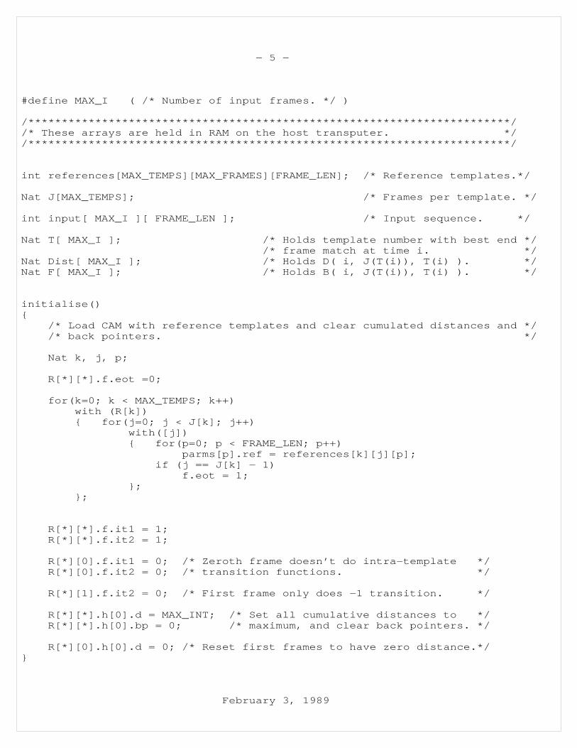
#define MAX_I ( /* Number of input frames. */ )
/************************************************************************//* These arrays are held in RAM on the host transputer. *//************************************************************************/
int references[MAX_TEMPS][MAX_FRAMES][FRAME_LEN]; /* Reference templates.*/
Nat J[MAX_TEMPS]; /* Frames per template. */
int input[ MAX_I ][ FRAME_LEN ]; /* Input sequence. */
Nat T[ MAX_I ]; /* Holds template number with best end *//* frame match at time i. */
Nat Dist[ MAX_I ]; /* Holds D( i, J(T(i)), T(i) ). */Nat F[ MAX_I ]; /* Holds B( i, J(T(i)), T(i) ). */
initialise(){
/* Load CAM with reference templates and clear cumulated distances and *//* back pointers. */
Nat k, j, p;
R[*][*].f.eot =0;
for(k=0; k < MAX_TEMPS; k++)with (R[k]){ for(j=0; j < J[k]; j++)
with([j]){ for(p=0; p < FRAME_LEN; p++)
parms[p].ref = references[k][j][p];if (j == J[k] − 1)
f.eot = 1;};
};
R[*][*].f.it1 = 1;R[*][*].f.it2 = 1;
R[*][0].f.it1 = 0; /* Zeroth frame doesn’t do intra−template */R[*][0].f.it2 = 0; /* transition functions. */
R[*][1].f.it2 = 0; /* First frame only does −1 transition. */
R[*][*].h[0].d = MAX_INT; /* Set all cumulative distances to */R[*][*].h[0].bp = 0; /* maximum, and clear back pointers. */
R[*][0].h[0].d = 0; /* Reset first frames to have zero distance.*/}
February 3, 1989

− 6 −
find_prev_min(i){
/* This performs the decision function for both *//* between template and inter−template transitions and stores *//* the best previous cumulative distance in "R[*][*].h[0].d" *//* for every frame, together with the appropriate back pointer *//* in "R[*][*].h[0].bp". *//* 323 + 2190 = 2513 Cops. */
/* Between−template transitions, 4 + 319 = 323 Cops. */
with (R[*][0]) /* First frame in every template. */{ h[1].d = Dist[i−1]; /* Broadcast best previous minimum = 4 Cops. */
select ( h[0].d > h[1].d ){ h[0].d = h[1].d;
h[0].bp = i − 1;} /* 315 + 4 = 319 Cops. */
}
/* Intra−template transitions. 2*(546 + 549) = 2190 Cops. */
with (R[*]) /* For every template. */{ select ( [*].it1 == 1 )
{ h[1].d = [[−1]].h[0].d; /* Copy previous frame*//* distance forward = 546 Cops. */
select (h[1].d < h[0].d){ h[0].d = h[1].d;
h[0].bp = [[−1]].h[0].bp;}; /* 315 + 234 = 549 Cops. */
}select ( [*].it2 == 1 ){ h[1].d = [[−1]].h[0].d; /* Copy best of [[−1]] */
/* and [[−2]] forward = 546 Cops.*/select (h[1].d < h[0].d){ h[0].d = h[1].d;
h[0].bp = [[−1]].h[0].bp;}; /* 315 + 234 = 549 Cops. */
}}
}
February 3, 1989
− 7 −
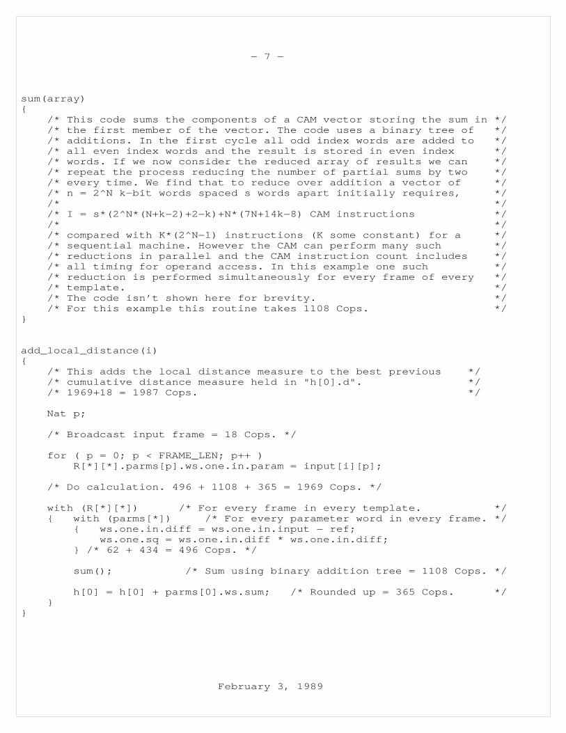
sum(array){
/* This code sums the components of a CAM vector storing the sum in *//* the first member of the vector. The code uses a binary tree of *//* additions. In the first cycle all odd index words are added to *//* all even index words and the result is stored in even index *//* words. If we now consider the reduced array of results we can *//* repeat the process reducing the number of partial sums by two *//* every time. We find that to reduce over addition a vector of *//* n = 2^N k−bit words spaced s words apart initially requires, *//* *//* I = s*(2^N*(N+k−2)+2−k)+N*(7N+14k−8) CAM instructions *//* *//* compared with K*(2^N−1) instructions (K some constant) for a *//* sequential machine. However the CAM can perform many such *//* reductions in parallel and the CAM instruction count includes *//* all timing for operand access. In this example one such *//* reduction is performed simultaneously for every frame of every *//* template. *//* The code isn’t shown here for brevity. *//* For this example this routine takes 1108 Cops. */
}
add_local_distance(i){
/* This adds the local distance measure to the best previous *//* cumulative distance measure held in "h[0].d". *//* 1969+18 = 1987 Cops. */
Nat p;
/* Broadcast input frame = 18 Cops. */
for ( p = 0; p < FRAME_LEN; p++ )R[*][*].parms[p].ws.one.in.param = input[i][p];
/* Do calculation. 496 + 1108 + 365 = 1969 Cops. */
with (R[*][*]) /* For every frame in every template. */{ with (parms[*]) /* For every parameter word in every frame. */
{ ws.one.in.diff = ws.one.in.input − ref;ws.one.sq = ws.one.in.diff * ws.one.in.diff;
} /* 62 + 434 = 496 Cops. */
sum(); /* Sum using binary addition tree = 1108 Cops. */
h[0] = h[0] + parms[0].ws.sum; /* Rounded up = 365 Cops. */}
}
February 3, 1989

− 8 −
get_best_end(i){
/* This finds the template with the best matching end frame and *//* extracts values for T[i], Dist[i] and F[i]. */
with ( R[*][*] ) /* For all frames of all templates. */{ select (label.eot == 1 && min( h[0].d ) )
{ T[i] = k; /* Retrieve it’s template number, */Dist[i] = h[0].d; /* cumulative distance, */F[i] = h[0].bp; /* and back pointer. */
}} /* 63 + 3 + 4 = 70 Cops. */
}
recognise(){
Nat i;
for ( i = 0; i < MAX_I; i++ ){ /* Once round the recognition loop takes 2513+1987+70 = 4570 Cops. */
find_prev_min(i); /* 2513 Cops. */add_local_distance(i); /* 1987 Cops. */get_best_end(i); /* 70 Cops. */
}
}
main(){
initialise();recognise();
}
Further work is necessary to determine the minimum precisions required atvarious stages in the processing to maintain good performance. In thisexample the input and reference parameters are represented as 7−bit 2s com−plement fixed point numbers. A Euclidean distance metric is calculated withfull precision to yield an 18−bit result. The 9−bit back pointers allow upto 512 frames in an input sequence, corresponding to over 5 seconds of unin−terrupted speech at 10ms per frame. With a sequence of 512 frames we couldget a cumulated distance requiring 18 + 9 = 27 bits of precision. We reducethe precision to 21 bits by losing some LSBs and having an overflow bitinstead of the MSBs. If the cumulated distance overflows then it is notlikely to be part of a succesful match. The exact precision reductionscheme adopted can be determined by experimentation.
February 3, 1989

− 9 −
_P_e_r_f_o_r_m_a_n_c_e__E_s_t_i_m_a_t_e_s
The algorithm is only a first attempt at performing connected speech recog−nition but is realistic in the amount of computation performed. The associ−ative C used to describe the algorithm has not been implemented but is usedhere to save presenting pages of obscure CAM instruction codes. Libraryroutines which perform the same operations as used in the above algorithmhave been written and tested on a functional simulation and so we can derivetiming figures for the recognition algorithm. The "Cops" figures annotatingthe listing are the number of CAM operations required to hand code the func−tions described in associative ’C’.
We find that for every frame of input we need to perform 4570 CAM instruc−tions. Apart from reading the best end frame value, all operations areformed from writes and searches. On the PADMAVATI architecture we can usethe transputer block move instructions to perform the role of a micro−sequencer reading out a stored sequence of write/search instructions fromtransputer RAM. One instruction executed in this manner requires two RAMfetches (one instruction, and one data) and two bus transfers. There is notransputer instruction fetch overhead because the block move is executed bytransputer micro−code. With a 25 MHz T−800 a RAM fetch takes 200ns on PARA−PET and a bus access takes approx 500ns, hence a single instruction willtake around 2*(200+500)=1400ns. The transputer has to execute some code toextract and broadcast the best end−frame but the time taken for this isnegligible. Hence the estimated time to perform recognition calculationsper frame is around 6.4ms, which is faster than real time if we assume a10ms frame rate. The algorithm could be further optimised for the CAMarchitecture, and if the transputer interface was replaced with a specialpurpose controller then the CAM cycle time could be reduced to around 200−250ns per instruction. The effect of these speed−up procedures would be toallow more processing per frame to enhance recognition performance.
Each frame occupies 19 CAM words, and each reference template can have up toaround 20−25 states, giving a total of 475 CAM words per template. Eachboard holds about 8000 CAM words and so a 16 board CAM array could processaround 270 reference templates simultaneously. During the calculation ofthe distance metric the CAM performance peaks at 1.2 GOPS for the 7−bit sub−tractions, 178 MOPS for the 7−bit to 14−bit squaring operation, and 65 MOPSwhen performing the summation of 14−bit numbers to give an 18−bit distancemetric. Special purpose hardware could outperform the CAM in both space andtime on this application, but the CAM has the advantage of being a generalpurpose computing structure.
February 3, 1989