gemini ii data sheet - cdesktopenv.org gemini ii data sheet.pdf · test -test register ... test7...
TRANSCRIPT

e: Description: Author: Company: Date: D o u icinn •
PRIVATE & CONFIDENTIAL
lilt)#
GEMINI II DATA SHEET
GEMR2DOC.WPD Acorn Gemini II ASIC Documentation F. T. Dart. Future Technology Devices Inti. Ltd .. April 17, 1995 2.0

PRIVATE & CONFIDENTIAL

PRIVATE & CONFIDENTIAL
TRADEMARKS
IBM PC and IBM PC AT are trademarks of International Business Machines Corporation . Intel 80386, 80486, and 80387 are trademarks of Intel Corporation.
TI486SXL is a trademark of Texas Instruments . MS-DOS and OS/2 are trademarks of Microsoft Corporation.
ARM is a trademark of Advanced RISC Machines Ltd.
DISCLAIMER
Future Technology Devices International makes no guarantees or warranties with regard to the information contained in this document. We reserve the right to make any changes to the specification of the product described without notice. It is the responsibility of customers to ensure that their use of the product does
not infringe upon any patent or other rights of third parties.
COPYRIGHT
This specification is copyrighted by Future Technology Devices International. You may not reoroduce, transcribe, transmit, store in a retrieval system, or prepare derivatives in any form or by any means any part
of this publication without the express written permission of Future Technology Devices International.

Table of Contents PRIVATE & CONFIDENTIAL
1. Introduction . . . . . . . . . . . . . . . . . . . . . . . . . . . . . . . . . . . . . . . . . . . . . . . . . . . . 4
2. Specification . . . . . . . . . . . . . . . . . . . . . . . . . . . . . . . . . . . . . . . . . . . . . . . . . . . . 5 2.1 ARM Interface . . . . . . . . . . . . . . . . . . . . . . . . . . . . . . . . . . . . . . . . . . . . . 5 2.2 486 Interface . . .. .. . . . . . .. : . . . . . . . . . . . . . . . . . . . . . . . . . . . . . . . . 5 2.3 1/0 Channel Bus Controller . . . . . . . . . . . . . . . . . . . . . . . . . . . . . . . . . . . . . 5 2.4 Cache Controller . . . . . . . . . . . . . . . . . . . . . . . . . . . . . . . . . . . . . . . . . . . . 5
2.4 .1 TAG SRAM . . . . . . . . . . . . . . . . . . . . . . . . . . . . . . . . . . . . . . . . 5 2.4 .2 Cache Operation . . . . . . . . . . . . . . . . . . . . . . . . . . . . . . . . . . . . . . 5
2.4 .2.1 ARM Read of memory written by 486 . . . . . . . . . . . . . . . . . 5 2.4 .2.2 486 Read of memory written by ARM . . . . . . . . . . . . . . . . . 5
2. 5 Memory Mapping Logic . . . . . . . . . . . . . . . . . . . . . . . . . . . . . . . . . . . . . . . 6 2.5 .1 Description of PC memory space . . . . . . . . . . . . . . . . . . . . . . . . . . . 6 2.5 .2 RISC PC memory space . . . . . . . . . . . . . . . . . . . . . . . . . . . . . . . . . 6 2.5.3 RISCOS support for memory allocation . . . . . . . . . . . . . . . . . . . . . . . 7 2.5.4 Memory mapping h~rdware . . . . . . . . . . . . . . . . . . . . . . . . . . . . . . 7 MBCRO - Memory Block Control Register 0 . . . . . . . . . . . . . . . . . . . . . . . 7 to . . . . . . . . . . . . . . . . . . . . . . . . . . . . . . . . . . . . . . . . . . . . . . . . . . . 7 MBCR7 - Memory Block Control Register 7 . . . . . . . . . . . . . . . . . . . . . . . 7
2 .6 Mailbox Logic . . . . . . . . . . . . . . . . . . . . . . . . . . . . . . . . . . . . . . . . . . . . . 8 MMCR - Memory Map Control Register . . . . . . . . . . . . . . . . . . . . . . . . . . 8 IOMCR 110 Map Control register . . . . . . . . . . . . . . . . . . . . . . . . . . . . . . 9 MASR - Mailbox Address/Status Register . . . . . . . . . . . . . . . . . . . . . . . . 10 MDR- Mailbox Data register . . . . . . . . . . . . . . . . . . . . . . . . . . . . . . . . 10
2. 7 Processor control logic . . . . . . . . . . . . . . . . . . . . . . . . . . . . . . . . . . . . . . . 10 PICR- Processor I Interrupt Control Register . . . . . . . . . . . . . . . . . . . . . 10 MISCR - Miscellaneous control reg . . . . . . . . . . . . . . . . . . . . . . . . . . . . 11 CFGR - Configuration register . . . . . . . . . . . . . . . . . . . . . . . . . . . . . . . 11 XREG - External register . . . . . . . . . . . . . . . . . . . . . . . . . . . . . . . . . . . 12 GPIO - GPIO registers . . . . . . . . . . . . . . . . . . . . . . . . . . . . . . . . . . . . . 12 FDD- FDC Dataregister . . . . . . . . . . . . . . . . . . . . . . . . . . . . . . . . . . . 12 FDC - FDC Status/Control register . . . . . . . . . . . . . . . . . . . . . . . . . . . . 12 TEST - Test register . . . . . . . . . . . . . . . . . . . . . . . . . . . . . . . . . . . . . . 13
2. 8 Internal Peripheral Subsystems . . . . . . . . . . . . . . . . . . . . . . . . . . . . . . . . . . 14 2.8.1 8254 Compatible Timer I Counter Subsystem .. . . . . . . . . . . . . . . . . . 14
2.8.1.1 Counter Description . . . . . . . . . . . . . . . . . . . . . . . . . . . . 14 2.8.1.2 Programming . . . . . . . . . . . . . . . . . . . . . . . . . . . . . . . . 15 2. 8 .1. 3 Write Operations . . . . . . . . . . . . . . . . . . . . . . . . . . . . . . 16 2.8.1.4 Read operations . . . . . . . . . . . . . . . . . . . . . . . . . . . . . . 17
2.8.1.4.1 Simple readback . . . . . . . . . . . . . . . . . . . . . . . 17 2.8.1.4.2 Counter Latch Command . . . . . . . . . . . . . . . . . . 17 2.8.1.4 .3 Read back Command . . . . . . . . . . . . . . . . . . . . 18
2.8.1.5 Mode Definitions . . . . . . . . . . . . . . . . . . . . . . . . . . . . . 19 2. 8 .1. 5.1 Mode 0 - Interrupt on Terminal Count . . . . . . . . . 19 2.8.1.5.2 Mode 1- Hardware Retriggerable One-shot . . . . . . 20 2.8.1.5 .3 Mode 2- Rate Generator . . . . . . . . . . . . . . . . . . 20 2.8 .1.5.4 Mode 3- Square Wave Mode . . . . . . . . . . . . . . . 20 2.8.1.5 .5 Mode 4- Software Triggered Strobe . . . . . . . . . . 21 2.8.1.5 .6 Mode 5 -Hardware Triggered Strobe . . . . . . . . . . 21
2. 8. 1. 6 Maximum and Minimum Counts . . . . . . . . . . . . . . . . . . . 21 2. 8.2 8259A Compatible Interrupt Controller Subsystem . . . . . . . . . . . . . . 22
2.8 .2 .1 Operation . . . . . . . . . . . . . . . . . . . . . . . . . . . . . . . . . . 23 2.8.2 .2 Interrupt Sequence . . . . . . . . . . . . . . . . . . . . . . . . . . . . . 23 2.8 .2.3 End of Interrupt . . . . . . . . . . . . . . . . . . . . . . . . . . . . . . 24 2.8. 2.4 Interrupt Priority . . . . . . . . . . . . . . . . . . . . . . . . . . . . . . 26
2. 8.2.4.1 Automatic Rotation . . . . . . . . . . . . . . . . . . . . . . 26 2. 8.2.4.2 Specific Rotation . . . . . . . . . . . . . . . . . . . . . . 26
- -' - - ·h~ T~•<>rrnnt C:ontroller Suosystem . . . . . . . . . 27

2.8.2.5.1 Initialisation Command Words .. ... ....... . . 2.8.2.5.2 Operation Command Words ......... .. .. . . .
2.8.3 DMA Controller Subsystem .. . .. ... . ... . ... . .. .. ... . . .. .
27 29 3 1
PRIVATE & CONFIDENTIAL
2. 8.3 .1 DMA Controller Registers . .. . ........... ....... . 2. 8. 3 .1.1 Current Address Register . . . . . . . . . . . . . . . . . . 2.8.3.1.2 Current Word Count Register . ........ .... . . 2.8.3.1.3 Base Address Register and Base Word Count
Registers .. . ............. . .... . .... . . . . 2.8.3.1.4 Command register .... .. .. .. .. ... . . . ... . 2.8.3 .1.5 Mode Register .. ... . ... ... ...... . ..... . 2.8.3.1.6 Request Register . .. ....... . ... . .... . . . . 2.8.3.1.7 Mask Register .. .... . .... . .. .... . .. . .. . 2.8.3.1.8 Status Register ... .. .. .... . ...... . ..... . 2.8.3.1.9 Temporary Register ..... .. ...... . .... . . . 2. 8. 3 .1.1 0 Special Software Commands . . . . . . . . . . . . .. .
2.8 .3.2 DMA Operation . ... .... . . . .. ... .. .. . . .. . .. . . . 2.8.3.2.1 Idle Cycle ..... .. ........ .. .. .. . . .... . 2.8 .3.2.2 Program Condition ...... . . .. ..... .. . . . . . 2.8.3.2.3 Active Cycle . . .. .. ........ .. . .. . .... . . 2.8 .3.2.4 Transfer Modes . .. . . . ...... .. . ...... .. . Single Transfer Mode . .... . ... .. ... . ..... ..... . . Block Transfer Mode .. . . . . ......... . .. .... .... . Demand Transfer Mode . . . . . . . . . . . . . . . . . . . . . . .. .
34 35
35 35 36 36 37 39 39 39 -+0 -+0 -+0 -+0 -+0 -+1 41 41
Cascade Mode . . . . . . . . . . . . . . . . . . . . . . . . . . . . . . . -+ 1 2.8.3.2.5 Transfer Types . . . . . . . . . . . . . . . . . . . . . . . . 41 Read Transfer . . . . . . . . . . . . . . . . . . . . . . . . . . . . . . . . -+ 1 Write Transfer . . . . . . . . . . . . . . . . . . . . . . . . . . . . . . . 42 Verify Transfer . . . . . . . . . . . . . . . . . . . . . . . . . . . . . . . -+2 Memory - Memory Transfer . . . . . . . . . . . . . . . . . . . . . . 42 2.8 .3.2 .7 Auto Initialisation . . . . . . . . . . . . . . . . . . . . . . . 42 2.8.3.2.8 Address Generation . . . . . . . . . . . . . . . . . . . . . 42
2.8.4 Port B register . . . . . . . . . . . . . . . . . . . . . . . . . . . . . . . . . . . . . . 43 2.8.5 8042 Keyboard Simulator . . . . . . . . . . . . . . . . . . . . . . . . . . . . . . . 44 2.8.6 Numeric Co-processor Interface . . . . . . . . . . . . . . . . . . . . . . . . . . 44
2.9 FIFO... . . . . . . . . . . . . . . . . . . . . . . . . . . . . . . . . . . . . . . . . . . . . . . . . 44
3. Signal Names sorted by Functional Group . . . . . . . . . . . . . . . . . . . . . . . . . . . . . . . 45
4. Signal Names sorted by Pin Number . . . . . . . . . . . . . . . . . . . . . . . . . . . . . . . . . . . 48
5. 208 Pin PQFP Package Dimensions . . . . . . . . . . . . . . . . . . . . . . . . . . . . . . . . . . . . 52
Appendix A - Example PCB Layout . . . . . . . . . . . . . . . . . . . . . . . . . . . . . . . . . . . . . 53
Appendix B- Board Level Schematic . . . . . . . . . . . . . . . . . . . . . . . . . . . . . . . . . . . . 54
Appendix C- Chip Level Block Diagram . . . . . . . . . . . . . . . . . . . . . . . . . . . . . . . . . . 55

Acorn Gemini 486 ARM Co-Processor ... ~\~~~~~1-V-A_T_E_&_ 1. Introduction C 0 N F I 0 E N T I A L
The Gemini II ASIC is specifically designed to interface a 80486 CPU to the Acorn ARM RISCPC Co-Processor Slot and to provide a level o PC compatible hardware thus allowing software designed to run on the IBM PC family to be run on this platform.
The ASIC is packaged in a 208 pin PQFP and functions from a supply voltage range of 4. 75 volts to 5.25v max. Maximum power consumption is 150 rnA.
The ASIC contains the following functional blocks :-
• ARl\1 CPU Interface
• 80486 CPU Interface
• 110 Channel Bus Controller - ISA slot bus support.
• Write Back Cache Controller - optional 2nd level WB cache controller supporting Ok I 32k I 128k I 512k external cache SRAM using lpc 32k x 8 SRAM as TAG RAM.
• Memory Mapping Logic- 4861ARM address translation logic.
• Mailbox- Peripheral Emulation Mailbox and Trapping Logic.
•
•
DMA Peripheral Emulation Support Logic - Support for ARM emulation of DMA based peripherals such as floppy disk controllers, various sound cards etc .
Processor Control Logic - provides interface for ARM to generate all control signals which would be generated by the hardware it emulates.
• Internal Peripheral Subsystem -
Twin 8259A compatible Interrupt Controllers in PC-AT compatible configuration.
Single 8254 compatible system timer in PC-AT compatible configuration.
Twin 8237 DMA Controllers and LS6 12 memory mapper in PC-AT compatible configuration.
PC-AT compatible "PORT B" logic.
8042 Keyboard Simulator for CPU Reset and Gate A20 functions.
80387 & 486DX Type Numeric Coprocessor Logic- FPU busy and FPU reset logic.
• FIFO - a sixteen level deep FIFO buffer is included to improve write performance from the 486 to system memory.
• 1st Level WB Cache Support- Support for CPU types with an internal 1st level write back cache.
• Power Management Support- Hardware support for "Green" CPU's which support a "stop clock" power down protocol.
Gemini II Data Sheet -Copyright (c) Future Technology Devices Inti. 1994,1995 Page 5

Acorn Gemini 486 ARM Co-Processor ASIC
2. Specification
2.1.ARM Interface
PRIVATE & CONFIDENTIAL
Interface to the the Acorn ARM RISC-PC Co-Processor Slot, including arbitration logic for access to the ARM bus.
2.2 80486 Interface
Intel 80486 SX I DX I DX2 I DX4 CPU or T.l. 486SXL-40 I 486SXL2-G66 or IBM/CYRJX BL486DXIDX2 CPU interface at a CPU bus speed of up to 33MHz ..
2.3 110 Channel Bus Controller
This provides the required interface for a real ISA slot bus, using a 2nd IC (FTD3482AP). enabling emulated peripherals to be replaced by PC plug-in cards.
2.4 Write Back Cache Controller
The optional inbuilt 2nd level cache controller supports one bank of cache SRAM providing either 32k or 128k of 2nd level cache in write through mode or 128k or 512k of 2nd level cache in write back mode.
Cache SRAM speed requirements are 35nS at 25MHz and 25nS at 33MHz.
2.4.1 TAG SRAM
The cache controller requires that an external SRAM be connected to serve as TAG memory for the cache. All comparators and control logic for the cache are contained internally to the ASIC.
TAG SRAM speed requirements are 30nS at 25MHz and 20nS at 33 MHz.
2.4.2 Cache Operation
Both the ARM and the 486 have 1st level caches between the processor and the main bus . The ARM has a write-through cache, and the 486 can have either a write-throgh or a write back cache depending on it's design. Gemini I had a write-through 2nd level cache, whereas Gemini II adds the option of a write-back 2nd level cache protocol in order to make 486 write access to the shared memory more effecient. The shared memory is coherent on the Gemini I, whereas this is not always the case when using a 1st or 2nd level write-back cache on Gemini II. Cache operation is as follows :-
2.4.2.1 ARM CPU Read of memory written to by 486 CPU
The 486 will write the data through into the appropriate area of system RAM . The ARM may possibly have stale data in its local cache. Therefore, AR!vl-side software will need to flush the relevant address regions in the ARM cache before reading any memory space which might have been altered by the 486. If a write back 1st or 2nd level cache is used , this must be flushed using the hardware mechanisms provided before the ARM CPU reads the data. Note- it may not actually be necessary for the ARM CPU to read the P.C.'s memory space as most peripheral emulation and communication functions can be carried out through the mailbox mechanism. Extended DMA support in Gemini II eliminates the requirement for the ARM CPU to move blocks of data about in PC memory space. Before the ARM CPU can read or write to PC memory space it MUST place the 486 CPU in a hold ( inactive ) condition by asserting BREQ ( MISC register bit 1 ) and polling the same register for bit 0 = 1.
Gemini II Data Sheet -Copyright (c) Future Technology Devices Inti. 1994.1995 Page 6

Acorn Gemini 486 ARM Co-Processor ASIC PRIVATE 8.
2.4.2.2 486 CPU Read of memory written by ARM CPU C 0 N F I 0 E N T I A L
The ARM CPU will write the data through to system RAM. The memory-mapping logic on the ASIC will monitor ( snoop ) this access and determine if the address concerned maps into data present in the PC second level cache. If so, the relevant entry in ·~e cache will be invalidated :. prevent stale data being read from the cache. Data transfer from A M CPU to -86 CPU is therefore transparent to software. See section 2.4.2.1 note on placing the 486CPU in an inactive state p ~ to r to the ARM CPU accessing the PC memory map space.
2.5 Memory Mapping Logic
This is needed to translate the memory addresses produced by the 486 CPU into suitable addresses for presenting to the ARM CPU bus and vice-versa. The different memory maps used by PCs and RISCOS, the Acorn ARM operating system, means that 486 CPU addresses have to be re-mapped into RISCO$ address space. RISCOS address space can be fragmented, so that the mapping logic has to translate contiguous blocks of PC memory into fragmented blocks of ARM CPU memory.
2.5.1 Description of PC memory space
A brief description of the standard PC-AT architecture is given below:
000000-09 FFFFh: OAOOOO-OAFFFFh: OBOOOO-OBFFFFh: OCOOOO-OEFFFFh:
OFOOOO-OFFFFFh:
100000-1 OFFEFh:
1 OFFFO-XXXXXXh:
FFFFFFFO-FFFFFFFFh:
(640K) System RAM (64K) Video memory on EGA & VGA adaptors (64K) Video memory on CGA/MDA adaptors (192K) Spare memory space - this has no pre-defined use . Typically, this contains extension ROMs (e.g. VGA BIOS at COOOO-C7FFFh), memory mapped network cards or SCSI adaptors . Also, 386 memory managers such as QEMM or EMM386 use the processor's paging facilities to map other bits of system RAM into this space so that DOS can use it as 'Upper Memory Blocks'. (64K) System ROM containing initialisation and BIOS code . Some systems have 128K of BIOS ROM from EOOOO-FFFFFh. As these ROMs are typically slow, most systems allow 'Shadow RAM': the ROM contents are copied into a block of system RAM which is then made read only and mapped in the place of the ROM.
(64K-16) - 'High memory area' used to hold some bits of DOS. Whether or not this area is accessible by real-mode programs is determined by the state of the A20 _GA. TE signal.
System RAM ('Extended memory'). This is only accessible by protected-mode programs.
After a hard reset, the 486 begins execution at address FFFFFFFOh.This normally contains a far jump into the BIOS ROM area. Gemini convens this address into OFOOOO-OFFFFFh in order to give a common address for the ROM BIOS area .
Gemini II Data Sheet - Copyright (c) Future Technology Devices Inti. 1994,1995 Page 7

Acorn Gemini 486 ARl\1 Co-Processo~ E &
2.5.2 RISC PC memory space C 0 N F J 0 E N T I A L
The RISC PC is equipped with one or two single I double density 72-pin SIMMs to provide its main RAM. Each SIMM is split into halves, providing 4 logically separate banks of RAM as follows:-
1000 OOOOh-lOxx xxxxh: 1400 0000h-14xx xxxxh: 1800 0000h-18xx xxxxh: !COO OOOOh-lCxx xxxxh:
First half of SIMM 0. Other half of SIMM 0. First half of SIMM 1. Other half of SIMM 1.
Each bank may be up to 64Mbytes in size , and typically not less than 512K. It is possible that SIMM 1 might be a different size to SIMM 0, or be not present at all. The memory mapping hardware in the ASIC needs to convert the 486' s address space into addresses in one or more of these memory areas .
In addition, Video RAM is available in the address range 02000000-02FFFFFFh ( according to the IOMD spec). There are potential performance gains to be made if VRAl\1 is used , as otherwise IO~iD has to use DMA transfers from system memory to VIDC, using up valuable bandwidth on the ARM I Gemini CPU bus.
As mentioned previously, the memory allocated to the ARM CPU by the RISCOS operating system may be fragmented, wheras the PC memory map is largely contiguous , so the memory mapping logic within the Gemini ASIC must be capable of convening contigouus PC memory into fragmented AR..t\11 memory space and vice-versa .
Gemini II Data Sheet -Copyright (c) Future Technology Devices Inti. 1994, 1995 Page 8

Acorn Gemini 486 ARM Co-Processor ASIC PRIVATE &
2.5.3 - Complete 110 space map C Q N F I 0 E N T j A L The IIO space decoding is based on the bottom 10 bits of the address, giving an effective addressing range of 0-3FFh. This is mapped out as follows:
Address Type Use 000-00Fh IntiMbox DMA controller 1 (chans 0 . . 3) 000-01Fh Alias for 000-00Fh 020-021h IntiiSAIMbox 8259 PIC no 1 022-03Fh Alias for 020-021 h 040-047h IntiiSAIMbox 8254 PIT (timer) 048-05Fh Alias for 040-047h 060h Int + Mbox 8042 keyboard controller 06lh Int Port B logic 062-063h Unknown 064h Int + Mbox 8042 keyboard controller 065-067h Unknown 068-06Fh Alias for 60-67h 070-071h Mbox RTC (Writes to 70h also used by NMI logic072-07Fh Unknown 080-08Fh IntiMbox DMA controller page regs 090-09Fh Mbox Unused OAO-OAlh IntiiSAIMbox 8259 PIC 2 no 2 OA2-0BFh Alias for OAO-OAlh OCO-ODFh IntiMbox DMA Controller 2 (chans 4 .. 7) OEO-OEFh Mbox Unused OFO-OFFh Int Coprocessor support
100-16Fh ISAIMbox Unused 170-17Fh ISAIMbox Alternate hard disk controller 180-lEFh ISAIMbox Unused lFO-lFFh ISAIMbox Hard disk controller
200-237h ISAIMbox Unused 238-23Fh Mbox Bus mouse emulation 240-277h ISAIMbox Unused 278-27Fh ISAIMbox Parallel port 3 280-2F7h ISAIMbox Unused 2F8-2FFh ISAIMbox Serial port 2
300-33Fh ISAIMbox Unused I NE2000 address 340-35Fh ISAIMbox Unused I NE2000 address 360-377h Mbox Unused I private PC-> ARM comms 378-37Fh ISAIMbox Parallel port 2 380-3AFh ISA Unused (send to ISA bus) 3B0-3BBh Mbox Video 3BC-3BFh ISAIMbox Parallel port 1 3C0-3DFh Mbox Video 3E0-3EFh ISA Unused I Serial 3 (send to ISA bus) 3F0-3F7h ISAIMbox Floppy controller 3F8-3FFh ISAIMbox Serial port 1 IMboxl = access sent to mailbox I ISA I = access sent to ISA bus if present IIntl = access sent to on-chip peripherals
Gemini II Data Sheet - Copyright (c) Future Technology Devices Inti. 1994,1995 Page 9

Acorn Gemini 486 ARM Co-Processor ASIC PR !\1,6. i E g
2.5.4 RISCOS support for memory allocation C Q N F ! 0 E N T j A L Any memory space used by the PC card will have to coexist with that used by other ARM software . The RISC PC version of RISCOS provides the OS_ DynamicArea SWI to manage memory allocation. The OS presents Gemini support software with a list of available pages of physical memory. of which we can choose those pages to be allocated to us. Physical pages are typically 4K long.
We need to be able to choose a set of pages with addresses capable of being mapped by the ASIC's hardware. If memory is full or fragmented, this might not be possible; the more flexible the memory mapping hardware, the more fragmented memory it will be able to cope with.
It is suggested that the support software would be able to reserve a certain area of memory (e.g. ll-.1) at boot time, which would be permanently unavailable to other applications . If, at the time the PC support application is run, no other memory can be found. it will still be able run in a limited way using this space.
2.5.5 Memory mapping hardware
The ARM/486 memory mapping logic has to be able to translate addresses in both direct ions ( PC ->ARM and ARM-> PC) so that ARM writes into PC space can correctly invalidate the data in the PC 2nd level cache. Mapping is done by splitting the space up into a number of variable sized blocks. which are given addresses on both the PC and the ARM sides . Each block will have a control register associated with it as follows :
MBCRO- Memory Block Control Register 0 . 03700000h Write only to MBCR7- Memory Block Control Register 7 0370001Ch Write only
bits 4 .. 0: block size select, as follows 00000 = 256K 00001 = 512K 00011 = 1M 00111 =2M 01111 = 4M 11111 = 8M
bits 8 .. 14: PC base address of blockbit 8 = PC Address bit Al8 bit 9 = PC Address bit A19
bit 14 = PC Address bit A24
This gives an allowable PC addressing range of 32Mbytes.
bits 18 .. 28: ARM base address of block bit 18 = ARM Address bit A 18 bit 19 = ARM Address bit A 19
bit -8 = ARM Address bit A28
This will allow mapping into the region 0-lFFFFFFFh, which includes all banks of DRAM and the system video RAM .
Gemini II Data Sheet -Copyright (c) Future Technology Devices Inti. 1994. 1995 Page 10

Acorn Gemini 486 ARM Co-Processor ASIC PRIVATE &
2.6 Mailbox Logic C 0 N F I 0 E N T I A L The 486 's 110 space, and areas in its memory space which are not "simple" RAM must be emulated by the ARM software. When the 486 makes a read or write access to these areas it is put in a wait state , unless the access is a write access and the mailbox is empty , whereas the 486 is allowed to continue. The ARM is informed of the address and related details of the access and processes write data or returns read data . The 486 ( if stopped ) is then allowed to continue.
This provides emulation for 486 accesses to 1/0 ports (other than to 1/0 devices which are implemented in hardware e.g. 8259) and to memory in the region OAOOOO-OFFFFFh. The following registers are provided :
MMCR - Memory Map Control Register
bits 1 .. 0: control for AOOOO-A 7FFFh bits 3 .. 2: control for A8000-AFFFFh bits 5 . . 4: control for BOOOO-B7FFFh
bits 23 .. 22: control for F8000-FFFFFh
03710000h Write Only
bits 25 .. 24: control for ROM space (8000 0000-FFFFFFFFh)
Each pair of bits encodes the following options
00 - Send access to mailbox This is intended for emulating video adaptors (and possibly other memory-mapped 1/0 e.g . network or SCSI cards), where the ARM needs to do some work for each 486 CPU access outwith the shared memory .
01 - Send access to ISA bus When an external ISA bus is fitted, some expansion cards will be memory-mapped in this region. This option allows accesses to this region to be passed through to the ISA bus . When an external ISA bus is not fitted, the software should not use this code.
10- Allow read-only access to ARM RAM (via memory mapper) 486 CPU Reads will be directed to the appropriate area of the ARM RAM; writes will be ignored . This would provide a shadow RAM function, for the main and video Bl OS ·I This area can be optionally cached by the 486 ( see CFGR register).
11 - Allow read/write access to ARM RAM (via memory mapper) This is used for providing a message area for data transfer between the 486 and ARM environments e.g . by the disk BIOS or Windows driver. In addition, this may be useful for emulating RAM on video adaptors and network cards. This area can be optionally cached by the 486 CPU (see CFGR register) .
Shadow RAM and Cache-Shadow RAM Feature
Access time to ROMS can be slow compared to the time taken to access system memory and cache . The Memory Map control register can be used to copy the contents of the system and video BIOS into fast system memory located ( shadowed ) at the same memory address range. This area of system memory is made READ ONLY as described in more detail in section 2.6, Mailbox logic . This greatly accelerates the performance of the BIOS. In addition, the shadow areas can also be defined readcacheable - this can further improve the system performance by allowing the BIOS to be cached as well as shadowed .
Gemini II Data Sheet - Copyright (c) Future Technology Devices Inti. 1994,1995 Page 11

Acorn Gemini 486 ARJ.\1 Co-Processor-tf~~~I~C~~-PRIVATE g
CONFIDENTIAL IOMCR 110 Map Control register 03720000h Write only
This controls the assigrunent of 110 space between the ISA bus/system-board logic and the mailbox mechanism. By default, all 110 accesses will go to the mailbox. Various bits in this register may be set to divert blocks of 110 to the ISA bus or on-chip peripherals.
bit 0: ports 0-1Fh, 80-9Fh and CO-DFh (DMA controller) 0 = Mailbox, 1 = on-chip DMA logic
bit 1: ports 170-17Fh, 1 F0-1 FFh (hard disk controller) 0 = Mailbox, 1 = ISA bus
bit 2: ports 100-16Fh, 180-1EFh (unused page 1 addresses) 0 = Mailbox , 1 = ISA bus
bit 3: ports 2F8-2FFh (Serial 2) 0 = Mailbox, 1 = ISA bus
bit 4: ports 200-237h, 240-2F7h (unused page 2 addresses) 0 = Mailbox, I = ISA bus
bit 5: ports 300-33Fh (miscellaneous expansion) 0 = Mailbox, 1 = ISA bus
bit 6: ports 340-35Fh (NE2000 emulation) 0 = Mailbox, 1 = ISA bus
bit 7: ports 378-37Fh (Parallel 2) 0 = Mailbox, 1 = ISA bus
bit 8: ports 3BC-3BFh (Parallel I) 0 = Mailbox, 1 = ISA bus
bit 9: ports 3F0-3F7h (floppy disk controller) 0 = Mailbox, 1 = ISA bus
bit 10: ports 3F8-3FFh (Serial 1) 0 = Mailbox, 1 = ISA bus
-bit 14, bit 11 : ports 20-21h and AO-Alh (8259 PIC #1 and #2) bl4:bll will be 00 =Mailbox 01 = ISA bus 1x = Internal PICs
bit 15, bit 12: ports 40-43h (8254 timer) bl5:b12 will be 00 =Mailbox 01 = ISA bus lx = Internal 8254
Gemini II Data Sheet -Copyright (c) Future Technology Devices Inti. 1994,1995 Page 12

Acorn Gemini 486 ARM Co-Processor ASIC
MASR - Mailbox Address/Status Register 03730000h Read only
bit 31: 1 =Access present, 0 =No access present bit 30: 1 = 16-bit transfer, 0=8-bit transfer
PRIVATE & CONFIDENTIAL
bit 29: 1 =Write, O=Read bit 28 : 1 =Memory access O=I/0 access bit 27: 1 =Access generated by ISA Bus Master , 0 =generated by 486 bits 26 .. 20: Always 0 ~ .., ~ v 1 [)PO ~ S ..... bits 19 . . 0: Address A19 . . AO ~ -
When the 486 (or possibly DMA controller) makes an access to an I/0 port or memory area decoded as 'mailbox' , bit 31 in the register is set and the others bits set to reflect the type of access being made. This register should be readable at any time without affecting any state ; if no access is currently being made bit 31 should be clear and all other bits can be undefined.
For a Read access, the 486 should be held in a wait state until the ARM can emulate the access and . provide suitable data by writing it to the Mailbox Data register (see below). For a write access. a
buffered-write scheme is used: when a single write access is made , the data is latched and the 486 allowed . to continue. If the 486 makes a second read or write access before the first has been acknowledged , it is held waiting until the first has been serviced .
MDR- Mailbox Data register 03730004h Read/Write
bits 0 .. 15 : data bits 0 .. 15 bits 16 .. 31: must be zero (on ARM read), ignored (ARM write)
When the 486 has made an access which has been trapped by the mailbox logic , the data for this access is passed via this register. For a 486 write , the ARM reads this register to obtain the data written and acknowledge the access . For a 486 read , the ARM supplies data by writing to this register.
Data transfer size and alignment
The 486 is capable of generating 1, 2, and 4-byte transfers to addresses with arbitrary alignment . To simplify the software, accesses transferred via the mailbox are reduced to aligned transfers only (i.e. word transfers are only made with 2-byte-aligned addresses), and 32-bit accesses are converted to two 16-bit accesses. The data is justified so that 8-bit accesses always appear in data bits 0 .. 7 of the MDR and 16-bit accesses always appear in dO . . d15 .
2.7 Processor control logic
Various other registers are provided for the ARM to configure the system and control the processor. These are as follows:
PICR- Processor I Interrupt Control Register
bit 0 : IRQ 1 bit (keyboard interrupt) bit 1: IRQ 3 bit (COM2 or Mouse) bit 2: IRQ 4 bit (COM1) bit 3: IRQ 5 bit (LPT2 or Network) bit 4: IRQ 6 bit (Floppy) bit 5 : IRQ 7 bit (LPTl) bit 6: IRQ 8 bit (RTC) bit 7: IRQ 9 bit (old IRQ2- video int) bit 8: IRQ 10 bit (spare)
03740000h Write only
Gemini II Data Sheet -Copyright (c) Future Technology Devices Inti. 1994,1995 Page 13

Acorn Gemini 486 ARM Co-Processor ASIC
bit 9: IRQ 11 bit (spare) bit 10: IRQ 12 bit (spare) bit 11 : IRQ 14 bit (IDE) bit 12: IRQ 15 bit (spare)
MISCR - Miscellaneous control reg
For write, bits are
bit 0: 1 = PowerGood active, 0 = reset 486
PRI VA i t & C 0 N F I 0 E r,~ T l A L
03750000h Read/Write
bit 1: 1 = Assert BREQ to 486 (to prevent it accessing shared memory space) bit 2: 1 = Enable "DMA Cycle Complete" interrupt on NPIRQ bit 3: 1 = Enable "DMA Cycle Complete" interrupt on NPFIQ ~t 4: 1 = Enable 8042 keyboard simulator for GATE A20 I CPU Reset Control.
0 = Use Bits 5 & 6 to control GATE A20 I CPU Reset it 5: (bit 4=0) 1 =Assert A20GATE signal
,.,bit 6: (bit 4=0) 1->0 transition= Assert CPU fast-:reset signal ..... b1t 8: 1 = Enable on chip memory write FIFO buffer
bit 9: 1 = Enable 2nd level cache bit 10: 1 = Enable mailbox access interrupt on NPIRQ bit 11: 1 = Enable maibox access interrupt on NPFIQ
For read, bits are
bit 0: 1 = HLDA asserted (486 acknowledges BREQ asserted) bit 1: 1 = ISABUS asserted (external input) bit 2: 1 = Suspend Acknowlege (Cyrix I TI I IBM CPU's) bit 3: 1 = Stop Grant (Intel CPU's)
0 1 HIZ- ~ ~t~ s ,a 12-E. '37 ~ e;>~O Cr CFGR - Configuration register 03760000h Write only
bits 3 .. 0: Set installed RAM size
0001: 1Mb 0010: 2Mb 0011: 3Mb 0100: 4Mb 0101: 5Mb 0110: 6Mb 0111: 7Mb 1000: 8Mb 1001: lOMb 1010: 12Mb 1011 : 14Mb 1100: 16Mb 1101 : 20Mb 1110: 24Mb 111 1: 28Mb 0000: 32Mb
Gemini II Data Sheet -Copyright (c) Future Technology Devices Inti. 1994,1995 Page 14

Acorn Gemini 486 ARM Co-Processor ASIC
For Write Through Level 2 Cache ( Rev2 Register bit 0 = 0) PRIVATE & CONFIDENTIAL
bit 4: 0 = 32K cache installed 1 = 12SK cache installed
For Write Back Level 2 Cache ( Rev2 Register bit 0 = 1 )
bit 4: 0 = S12K cache installed 1 = 12SK cache installed
bitS : 1 = Enable caching for PC system RAM (i.e. all RAM outside AOOOO-FFFFFh)
bit 6: 1 = Enable caching for memory mapped as 4S6 'Read-only' via the MMCR
bit 7: 1 = Enable caching for memory mapped as 'Read/Write' via the MMCR
XREG- External register 03770000h Write only
In Gemini ISA bus mode, the ASIC brings a decode for this register to an external pin - NERRN. pin 12 to allow external ARM controlregisters to be attached on-card . Its use is otherwise undefined at present.
GPIO- GPIO registers 037S0000/4/S/Ch Write only
The Gemni ASIC implements four general purpose 1/0 decoders which can be used to redirect I/0 addresses to the external !SA bus option ( in Gemini ISA bus mode only ) .
bit 0: comparator bit for CPU address PA2 bit 1: comparator bit for CPU address PA3 bit 2: comparator bit for CPU address PA4 bit 3: comparator bit for CPU address PAS bit 4: comparator bit for CPU address PA6 bit S: comparator bit for CPU address PA 7 bit 6: comparator bit for CPU address PAS bit 7: comparator bit for CPU address PA9
bitS: = 1 enable comparator for CPU address PA2 bit 9: = 1 enable comparator for CPU address PA3 bit 10: = 1 enable comparator for CPU address PA4 bit 11: = 1 enable comparator for CPU address PAS bit 12: = 1 enable comparator for CPU address PA6 bit 13: = 1 enable comparator for CPU address PA7 bit 14: = 1 enable comparator for CPU address PAS bit 1S: = 1 enable comparator for CPU address PA9
bit 16: = 1 enable decoder
Gemini II Data Sheet -Copyright (c) Future Technology Devices Inti. 1994,1995 Page 15

Acorn Gemini 486 ARM Co-Processor A~ VAT E g CONFIDENTIAL
DMAPD - PC DMA Peripheral Data register 03790000h Read/Write
PC DMA Peripheral write emulation
This is used to emulate ISA bus peripheral devices that use DMA channels for data transfer. such as floppy disc controllers, some networking, sound and multimedia peripheral cards .
For DMA-WRITE cycles ( MEMWR +lORD) the ARM CPU writes the DMA peripheral data to this register prior to initiating a PC DMA cycle via the DMAPC register. The PC DMA controller will then write the data from this register into the PC memory space.
For DMA-READ cycles ( MEMRD + IOWR) the ARM CPU will initiate a DMA cycle via the DMAPC register. The PC DMA controller will read the data from PC system memory and load the DMAPD register with the resulting data value which can then be read by the ARM CPU .
This register is 8 bits wide when DMA channels 0 to 3 are selected for emulation and 16 bits wide when channels 5 to 7 are selected for emulation and must be programmed as such. DMA Channel 4 is the cascade channel in PC architecture and is not normally used for data transfer .
DMAPC- PC DMA Peripheral Status/Control register 03790004h Read/Write
Data is transferred between the DMAPD register and the PC system memory under the control of the PC compatible DMA controller. The DMAPC register is used to initiate emulated DMA cycles under control of the ARM CPU. There are 3 different modes of DMA transfer, SINGLE, DEMAND and BLOCK mode and the DMAPC register is used sightly differently in each case to control the transfer of data to/from the DMAPD register.
SINGLE MODE ,. The DMA controller does one read or write cycle, then releases control of the system back to the CPU. Usually "slow" perpherals that do not require a high rate of data throughput use single mode.
DEMAND MODE - The DMA controller transfers 1 packet of data to/from the peripheral , then releases control of the system back to the CPU. The number of words of data transferred is variable and controlled by the peripheral asserting it's DMA request line. Usually peripherals that require a higher data rate and have some inbuilt FIFO buffering capability use demand mode .
BLOCK MODE -The DMA controller transfers a fixed size block of data between the peripheral and the PC system memory. The block size is programmed into the DMA controller and is terminated by the DMA controller issuing a TERMINAL COUNT signal back to the peripheral. Usually peripherals that require a higher data rate and that have data storage in the form of onboard memory use block mode.
Register Write Operation- Bit 0
In single mode, Bit 0 is initially set to 0. Setting Bit 0 to 1 initiates the one cycle DMA transfer by asserting DMA request to the selected DMA channel. On completion of the transfer bit 0 should be reset to 0 in preparation for the next transfer cycle. In demand mode, operation is similar to single mode but the DMA request remains active until bit 1 of this register is set. Bit 0 should be transitioned from a 0 to 1 as many times as are required by the size of the data packet being transferred. On the last transfer, bit 1 should also be set which removes the DMA request and returns control of the PC subsystem back to the CPU. In block mode , operation is similar to demand mode, but the cycle is terminated by the PC DMA controller issuing a terminal count status. The ARM based emulation software must continue to read
Gemini II Data Sheet -Copyright c) Furure Technology Devices Inti. 1994,1995 Page 16

Acorn Gemini 486 ARM Co-Processor ASIC
1 supply data to/from the DMAPD register until the terminal count status = 1. p R J VAT E & Register Write Operation- Bit 1 C 0 N FIDE NT I A L
This bit is only used in demand mode transfers to indicate that the emulated peripheral is transferring the last data word in the packet and to terminate the current DMA cycle.
Register Read Operation ( all modes )
Bit 0: 1 = DMA read/write transfer cycle complete Bit 1: 1 = DMA read transfer cycle complete Bit 2: 1 = DMA write transfer cycle complete Bit 3: 1 = DMA terminal count asserted
Note : demand and block mode transfers consist of a number of individual transfer cycles.
DMACS- PC DMA Channel Select register
Bit 0: DMA Channel Select Bit 0 Bit 1: DMA Channel Select Bit 1 Bit 2: DMA Channel Select Bit 2
03790008h Write
These 3 bits define which of the DMA channels are being selected for emulation. Channel 4 would not normally be selected as this is hardwired as the DMA cascade channel in "real" pc 's. The peripheral emulation software can change this register "on-the-fly" to emulate several peripherals on different DM-A channels, but it is not allowed to change this in the middle of an ongoing DMA transfer cycle .
DMAES - PC DMA Emulation Status register 03790008h Read
This register allows the ARM emulation software some visibility of how application software has programmed up the PC DMA controller in order to assist with the emulation of DMA peripheral devices. The status of all 8 channels of the DMA controller can be read by this register- the channel number being selected by the DMACS register.
Bits 1,0 define the DMA transfer type as follows:-00 Demand Mode 01 Single Mode 10 Block Mode 11 Cascade Mode
Bits 3,2 define the DMA cycle transfer direction as follows :-00 DMA Verify Transfer Cycle 01 DMA Write Transfer Cycle 10 DMA Read Transfer Cycle 11 Illegal - Initiates both read and write cycles .
Bit 4: 1 = Autoinitialise Bit 5 : 1 = Address Decrement Bit 6: l = DMA Channel masked Bit 7: 1 = SIW DMA request
Gemini II Data Sheet - Copyright (c) Future Technology Devices Inti. 1994, 1995 Page 17

Acorn Gemini 486 ARM Co-Processor AS~IC~---PR ~V ATE &
REV2 - Gemini Rev 2 New Function Control register 037 AOOO · ·@ N-JY I 0 E N T I A L
Note : All bits default to logic "0" on power-up for Gemini 1 compatibilty.
Bit 0 : WBMODE
Bit 1: WBTMG
Bit 2: FAEN
Bit 3 : KBMODE ----Bit 4 : FIF016
Bit 5: WBCPU
Bit 6 : RMUADV
Bit 7: SUSP
Bit 8: ENRMUBUF
Bit 9 : INVONHIT
0 = Write-Through 2nd level cache algorithm 1 = Write-Back 2nd Level cache algorithm. 0 = 486 CPU bus speed < = 33MHz 1 = 486 CPU bus speed > = 33MHz 1 = Enable FIFO Address Compare algorithm
1 = Reset kbd simulator on PWR GOOD inactive ·
0 = 4 level FIFO 1 = 16 level FIFO 0 = 486 CPU with 1st level WT cache 1 = 486 CPU with 1st level WB cache 1 = Advance initial cache RMU cycle address timing
1 = Request Clock Suspend Mode in 486 with PMU fearures
1 = Store entire cache RMU line in an extended FIFO buffer
1 = Invalidate 2nd level cache on a write hit only
Bit 10: WRBRST 1 = Write a 486 CPU 16 bit access as a double 8 bit ARM burst cycle -Pft·-:z.J~6
Bit 11: ENL2FL
Bit 12: ENCLKO
. Bit 13: CYRIXWB
Bit 14: INTELWB
L.,..o-t.~J-(...(... "'~ ;v(..rl.-;:Y'-~~*.,w!'J '-'4""\. ,•. ~:J.:"-IJ.1 ~ 1 t,..Jc/2..(.(
·1 = Automatically Flush the level 2 cache on CPU hold request
0 = Disable CPU clock in power management mode 1 = Enable CPU clock in power management mode
1 = Cyrix CPU WB Flush I Invalidate interface
1 = Intel CPU WB Flush I Invalidate interface
Bit 15: REV2 1 = Set data bits 20 to 26 to logic level "1 ". Used to identify Gemini II silicon.
TEST- Test register
bit 0: TEST! -hardware test signal bit 1: TMRTEST - hardware test signal bit 2: ENDMA - hardware test signal
IN 373 0
bit 4: TMG 1 -modifies the timing of the ARM bus interface bit 5: TMG2- modifies the timing of the ARM bus interface bit 6: TEST2 - hardware test signal bit 7: TEST3- hardware test signal bit 8: TEST4 - hardware test signal bit 9: TESTS -hardware test signal bit 10: TEST6- hardware test signal bit 11: TEST7 - hardware test signal
037FOOOOh Write only
Gemini II Data Sheet - Copyright (c) Furure Technology Devices Inti. 1994,1995 Page 18

Acorn Gemini 486 ARM Co-ProcessarM~S. TE &
2.8 Internal Peripheral Subsystems C 0 N F l 0 EN T I.A L
The Gemini ASIC integrates a number of peripheral subsystems which are fully compatible with the PC-AT architecture .
These subsystems provide two 8237 compatible DMA controllers, two 8259A compatible interrupt controllers and one 8254 compatible timer/counter. These peripherals provide all of the logic required for the X bus of an AT compatible design with the exception of a 146818 Real Time Clock I CMOS RAM and a keyboard controller.
2.8.1 8254 Compatible Timer I Counter Subsystem
This subsystem contains three 16 bit counter I timers ( counters 0 - 2 ) which can be progranm1ed to
count in either binary or BCD . Each counter operates independently of the others . The clocks for each of the three counters are tied to a single internal clock of 1.19 Mhz. The gate inputs of counters 0 and
.1 are tied high to enable those counters at all times. The gate input of counter 2 is connected to bit 0 of the internal PORT B register at hex address 61. Only one of the timer/counter outputs is available externally . Counter 0 output ( OUTO ) is connected internally to the IRQO of the interrupt controller subsystem. Counter 1 output ( OUTl ) is output from 82C3482AP and is used to generate refresh requests within 82C3481XMVL50. Counter 2 output (. OUT2 ) is used internally for speaker sound generation.
Each counter can be programmed to operate in one of the six following modes -
ModeO Mode 1 Mode2 Mode 3 Mode4 Mode 5
Interrupt on terminal count Hardware re-triggerable one shot Rate generator Square wave mode Software triggered strobe Hardware triggered strobe ( retriggerable )
For counters 0 and 1, Mode 1 and Mode 5 are of limited use since their gate inputs are tied high.
2.8.1.1 Counter Description
Each counter consists of a control register, a status register, a 16 bit counter element, a pair of 8 bit counter input latches, and a pair of 8 bit counter output latches.
The control word register specifies the operating mode of the counter. The status register monitors the current contents of the control word register nd also the current condition of the counter. The counter element is a 16 bit synchronous counter. New counts are loaded and the count is decremented on the falling edge of the internal clock input. The counter does not stop when it reaches zero. In Modes 0,1 ,4,and 5 the counter wraps around to FFFF hex in binary mode or 9999 in BCD mode, while in Modes 2 and 3 the counter is reloaded with the initial count and counting continues. The largest possible initial count is 0000.
The counter element is indirectly loaded by first writing one or optionally two bytes to the input latches . Both bytes are then transferred simultaneously to the counter element. The counter element may be read back indirectly via the counter output latches.
Gemini II Data Sheet -Copyright (c) Future Technology Devices Inti. 1994,1995 Page 19

Acorn Gemini 486 ARM Co-Processor-tf~~~l~C:r--~-lYRIVATE &
2.s.1.2 Programming C 0 N F I 0 E N T I A L
After a power on. reset, the state of the counter/timer subsystem is undefined. Each counter must be programmed before it can be used . Each counter is programmed by writing a control word then an initial count.
The control word is written to the control word register. The control word itself specifies which counter is being programmed. The initial count is written into the counter input latches. The format of the initial count ( one or two bytes) is determined by the control word that was used .
The 110 address map used by the timer/counter subsystem is as follows-
Address (hex) Function
40 Counter 0 - read I write
41 Counter 1 - read I write
42 Counter 2 - read I write
43 Control Register - write only
Gemini II Data Sheer -Copyright (c) Furure Technology Devices Iml. 1994 ,1 995 Page 20

Acorn Gemini 486 ARM Co-Processor ASIC ------------------
2.8.1.3 Write Operations PRIVATE g
CO NFI OENTIAL When programming a counter, the following sequence must be observed -
1) for each counter, the control word register must be written.
2) the initial count must follow the format specified in the control word.
A new initial count may be written to the counter at any time after programming without first rewriting the control word . The new count must follow the programmed count format.
The control word is written to 110 address 0043 hex and has the following format -
Bits Function
7,6 SC1 , SCO Select which counter this control word is written to
0 0 Select counter 0
0 1 Select counter 1
1 0 Select counter 2
1 1 Reserved for counter read back command
5,4 RWl , RWO Determine the counter input latch loading format
0 0 Reserved for counter latch command
0 1 Read I write least significant byte only
1 0 Read I write most significant byte only
1 1 Read I write least significant then most significant byte
3,2,1 M2-MO Select the counter operating mode
0 0 0 Select Mode 0
0 0 1 Select Mode 1
X 1 0 Select Mode 2
X 1 1 Select Mode 3
1 0 0 Select Mode 4
1 0 1 Select Mode 5
0 BCD Select counter mode
0 Select 16 bit binary counter mode
1 Select 4 decade BCD counter mode
Gemini II Data Sheet -Copyright (c) Future Technology Devices Inti. 1994,1995 Page 21

Acorn Gemini 486 ARM Co-Processor ASIC ------~----------
2.8.1.4 Read operations c i"' : \1 1\ T -t () , K: · h 1 a
CO NF! DENT!AL Three methods exist for reading back the status and count of each counter element.
2.8.1.4.1 Simple readback
The current count of any counter/timer may be read at any time by a I/0 read of address 40 hex. 41 hex, or 42 hex as appropriate . Note that the count may be in the process of changing when it is read giving unreliable results unless the counting is inhibited using the gate input. This control is only available in counter 2 via bit 0 of PORT B.
The count must be read back in accordance with the byte format programmed in R\Vl. RWO in me Control Word Register.
2.8.1.4.2 Counter Latch Command
This command is written to the Control Word Register and is distinguished from a Control Word by setting data bits 4 and 5 ( RWO and RWl ) low . A counter is selected by data bits 6 and 7 ( SCO and SCI ). The selected counter's output latches latch the count at the time the command is received.
This count is held in the latches until read by the CPU or the counter is reprogrammed. when me latches return to following the count. Multiple Counter Latch Commands to the same counter without reading me counter cause all but the first command to be ignored. The count read will be that latched by the first command. Counter Latch Commands may be issued to more than one counter before reading the count latched by previous commands.
The count must be read back in accordance with the byte format programmed in the Control Word Register.
The Counter Latch Command format is shown below -
I Bits I Function I 7,6 SC 1, SCO Select counter to be latched
0 0 Select counter 0
0 1 Select counter 1
1 0 Select counter 2
1 1 Reserved for read back command
5,4 RWl, RWO Specify Counter Latch Command
0 0 Must be 0 0
3.2, l ,0 X X X X Don 't care for Counter Latch Command
Gemini II Data Sheet -Copyright (c) Furure Technology Devices Inti. 1994, 1995 Page 22

Acorn Gemini 486 ARM Co-Processor ASIC -----------------2.8.1.4.3 Read back Command
The Read Back Command allows the user to check the count value , the programmed mode, and the current states of the counter/timer OUT pin and the Null Count flag of each counter. The command is written to the Control Word Register and is distinguished from a Control Word by setting bits 6 and 7 ( SCO and SCI ) high .
The command has the following format -
I Bits I Function I 7,6 SCl,SCO Specify Read Back Command
1 1 Must be 1 1 to specify Read Back Command
5 COUNT
0 Latch count of selected counter(s)
1 Don't latch count
4 STATUS
0 Latch status of selected counter(s)
1 Don't latch status
3,2,1 Select counter
XXI Select counter 0
X 1 X Select counter 1
1 X X Select counter 2
0 Should be programmed with 0
The read back command may be used to latch the count of a timer/counter by setting the COUNT bit to 0 and selecting the desired counter. The count of more than one timer/counter may be latched with one Read Back Command by selecting the appropriate counters . Each counter's latched count is held until it is read or the counter is reprogrammed. The counter is unlatched when read, but other counters remain latched.
If multiple read back commands are issued to the same counter before it is read, all but the first are ignored. The count read will be that latched by the first command. The count must be read back according to the format programmed in the RWl, RWO bits of the Control Word Register for a counter.
Gemini II Data Sheet -Copyright (c) Future Technology Devices Inti. 1994,1995 Page 23

PRIVATE g Acorn Gemini 486 ARM Co-Processor Am<f I 0 ENTIA L
The Read Back Command may also be used to latch status information for selected counter(s) by setting the STATUS bit to 0. Status must be latched ro be read. The latched status is read by a read of mat counter. The counter status format is shown below -
I Bits I Function I 7 OUT The state of the output of the timer/counter
1 Output is 1
0 Output is 0
6 NULL COUNT
1 Null Count
0 Count available
5,4 RW1, RWO from Control Word Register
3,2,1 M2, M1, MO from Control Word Register
0 BCD from Control Word Register
The NULL COUNT bit indicates when the last count written to the counter input latches has been loaded into the counting element. This bit is high until the count has been loaded, when it goes low. If the timer/counter count is latched or read while NULL COUNT is high then the value read will nor reflect the last count written.
If multiple status latch operations are performed to the same counter without reading the status, all but the first are ignored. The status read will be that latched by the first command.
Both count and status may be latched together by setting both COUNT and STATUS bits low. In this case the first read operation to a counter will return the latched status. The next one or two reads ( depending on the format programmed into the Control Word Register) will rerum the latched count.
2.8.1.5 Mode Definitions
Counter 0 and counter 1 have restrictions on their modes of operation and so counter 2 will be used to describe the modes available . The following terms are used-
CLK pulse : a rising edge followed by a falling edge on the internal 1.19 Mhz input to the timer/counter subsystem Trigger : A rising edge on bit 0 of Port B Counter load : the transfer of a count from the counter input latches to the counting element. Gate : The state of bit 0 of the Port B register
2.8.1.5.1 Mode 0 -Interrupt on Terminal Count
Typically used for event counting. After the Control Word is written, the counter/timer output is low, and remains low until the counter element reaches zero. The output then goes high and remains high until a new count or a new Mode 0 Control Word is written.
Gate = 0 disables counting, Gate = 1 enables counting. Gate has no effect on the state of the counter output.
Gemini II Data Sheet -Copyright (c) Future Technology Devices Inti. 1994, 1995 Page 24

PRIVATE & Acorn Gemini 486 ARM Co-Processor ~Sl(f I 0 ENTIA L
The counter element is loaded at the first CLK pulse after the Control Word and initial count are loaded. This CLK pulse does not decrement the counter, so for an initial count of N, the output does not go low until N + 1 CLK pulses. When both initial count bytes are required, the counter element is loaded after the high byte is written.
When a new initial count is written to the counter, the counter element is loaded on the next CLK pulse and counting will continue from the new count. If a new count is loaded when Gate = 0. it will still be loaded on the next CLK pulse, but counting will not continue until Gate goes high again. In this case the output will go high N CLK pulses later since no CLK pulse is needed to load the counter ( this has already been done ) .
2.8.1.5.2 Mode 1- Hardware Retriggerable One-shot
The timer/counter output will be high after writing the Control Word. The output will go low on the CLK pulse following a trigger, and will remain low until the count reaches zero. The output will then go high and remain high until the CLK pulse following the next trigger. An initial coum of N results in a one-shot pulse N CLK cycles long.
The one-shot is retriggerable - any trigger while the output is low reloads the coumer elemem and extends the length of the pulse by a further N CLK cycles.
If a new count is written to the counter during a one-shot pulse, the current pulse is not affected unless the counter is retriggered. In such a case, the counter element is reloaded with the new count and the pulse continues until the counter reaches zero .
2.8.1.5.3 Mode 2- Rate Generator
This mode functions as a divide by N counter. After writing the Control Word, the timer/counter output is high. After writing the Control Word and the initial count, the counter element is loaded on the next CLK pulse. The output goes low N CLK pulses after the initial count is written and stays low for one CLK pulse . On the following CLK pulse, the output goes high again and the counter elemem is reloaded with the initial count and the process is repeated. For an initial count of N, the cycle is repeated every N CLK cycles .
Gate = 1 enables counting, Gate = 0 inhibits counting. If Gate goes low during an output pulse , the output goes high immediately. A trigger reloads the counter element on the next CLK pulse and the output goes low N CLK pulses later.
Writing a new count while counting does not affect the current sequence unless a trigger is received , in which case the counter will be reloaded with the new count on the next CLK pulse and counting will continue from the new count. Otherwise, the new count will be loaded at the end of the current cycle.
2.8.1.5.4 Mode 3- Square Wave Mode
Similar to Mode 3 except for the duty cycle of the timer/counter output. The output is high following the writing of the Control Word. After writing the Control Word and the initial count , the counter is loaded on the next CLK pulse. When ·half of the initial count has expired, the output goes low and stays low for the remainder of the count. This sequence is repeated indefinitely. An initial count of N results in a square wave with a period of N CLK cycles.
Gate = 1 enables counting. Gate = 0 disables counting. If Gate goes low while the output is low , the output is set high immediately . A trigger reloads the counter with the initial count on the next CLK
Gemini II Data Sheet - Copyright (c) Future Technology Devices Inti. 1994, 1995 Page 25

Acorn Gemini 486 ARM Co-ProcessoF-ASIC--,_ R' ' ' ~-E-~ I I ; ~ I '< I .. , 1 1 (!.
pulse. CON FIDENTIAL
If a new count is written during a count sequence, the current sequence is not affected. If a trigger is received after writing a new count but before the end of the current half cycle, the counter will be loaded with the new count on the next CLK pulse and the count will continue from the new count. Otherwise the new count will be loaded at the end of the current half cycle .
When the initial count is even, the output will have a 50% duty cycle- high for N/2 CLK pulses and low for N/2 CLK pulses if the initial count is N. If N is odd, then the output will be high for (N + 1 )i2 CLK cycles and low for (N-1) CLK cycles.
2.8.1.5.5 Mode 4- Software Triggered Strobe
Following the writing of the Control Word, the timer/counter output will be high. When the initial count expires, the output will go low for one CLK pulse then go high again . Gate = 1 enables counting. Gate = 0 disables counting. The state of Gate has no effect on the output.
The counter element will be loaded on the first CLK pulse following the writing of the Control Word · and the initial count. This clock pulse does not decrement the count, so for an initial count ofN. the output will not go low until N + 1 CLK cycles .
If a new initial count is written during a count sequence, it will be loaded into the counter element on the next CLK pulse and counting will continue from the new count.
2.8.1.5.6 Mode 5- Hardware Triggered Strobe
Writing the Control Word sets the timer/counter output high. Counting is triggered by a rising edge on Gate . When the initial count has expired, the output will go low for one CLK cycle then go high again.
The counter element is loaded on the first CLK pulse after a trigger following the writing of the Control Word and the initial count. This CLK pulse does not decrement the counter. The output will strobe low after N + 1. CLK pulses after the trigger.
If a new count is written during a count sequence, the current sequence will not be affected unless a trigger occurs. If a trigger occurs after the new count is written but before the current count expires then the counter will be loaded with the new count on the next CLK pulse and the count will continue from the new value .
2.8.1.6 Maximum and Minimum Counts
The table below shows the allowable values for minimum and maximum initial count values for the different modes of operation -
I Mode I Min. Count I Max. Count I 0 1 0
1 1 0
2 2 0
3 2 0
4 1 0
Gemini II Data Sheet - Copyright (c) Future Technology Devices Inti. 1994,1995 Page 26

Acorn Gemini 486 ARM Co-Processor ASIC
I I p r'; lljJ\ T~ c
Mode Min. Count Max. Count t-:11 1-' : 1- a . ' I W ' ~ . \-,.
c("'~r l :-q- ~' '1 ;.. ! ! ?""" l! I ~ · ~ ' .: i
I I ..._, • I 1 - '-- ! t , I,...,.., ._
5 1 0 ··---·-- --
2.8.2 8259A Compatible Interrupt Controller Subsystem
This subsystem comprises two 8259A compatible interrupt controllers - a Master and a Slave. The Master controller is located at 1/0 address 020- 021 hex and the Slave at OAO - OAl hex. The two controllers are internally cascaded using the IR2 input of the Master controller and the output of Timer 0 of the Counter I Timer subsystem is connected to IRO input of the Master controller. This arrangement matches that of the IBM PC-AT.
This description of the Interrupt Controller subsystem applies to both Master and Slave controllers unless otherwise stated. Whenever register addresses are used, the address for the Master controller will be listed first e.g 020H (OAOH).
The following table lists the assignment of the interrupt inputs to the Master and Slave controllers -
I Controller I Channel N arne I Source I Master IRO Counter I Timer subsystem OUT 0
Master IR1 IRQ 1 input pin
Master IR2 Slave controller cascade connection
Master IR3 IRQ3 input pin
Master IR4 IRQ4 input pin
Master IRS IRQS input pin
Master IR6 IRQ6 input pin
Master IR7 IRQ7 input pin
Slave IRO IRQ8# input pin ( Real Time Clock )
Slave IR1 IRQ9 input pin
Slave IR2 IRQ 10 input pin
Slave IR3 IRQ 11 input pin
Slave IR4 IRQ12 input pin
Slave IRS IRQ 13 input pin
Slave IR6 IRQ14 input pin
Slave IR7 IRQ15 input pin
2.8.2.1 Operation
The interrupts at the IR inputs to the controller subsystem are handled by the Interrupt Request Register ( IRR ) and the In Service Register ( ISR ) within the Master and Slave controllers. The IRR is used
Gemini II Data Sheet ... Copyright (c) Future Technology Devices Inti. 1994, 1995 Page 27

PR !\/ ., 1 r 0 ! .V i-\! C. <::i
Acorn Gemini 486 ARM Co-Processor ASfcFI DENTIAL
to store the request from all of the interrupt channels which are requesting service . Bits in this register are referred to using the Channel Name IR0-7 . The ISR is used to store all the channels which are currently being serviced. Bits in this register are referred as IS0-7. Each controller has a Mask Register which may be used to disable any of the interrupt channels to that controller .
Based on the contents of these three registers, a priority resolver issues an interrupt request to the CPU when a request for interrupt service is received. During CPU interrupt acknowledge cycles. an interrupt vector is supplied to the CPU from the contents of the Vector Register.
2.8.2.2 Interrupt Sequence
The following sequence occurs when a request for an interrupt service is received -
1) One or more of the interrupt requests ( IR0-7) becomes active. setting the corresponding IRR bit(s) .
2) The priority of the request(s) is resolved and the INTR output is asserted if appropriate.
3) The CPU responds with an interrupt acknowledge cycle.
4) During the second part of the INT A cycle a vector is placed onto XD data bus bits 0-7 for reading by the CPU . This vector has the following format -
I I XD7 I XD6 I XD5 I XD4 I XD3 I XD2 I XD1 I XDO I IR7 V7 V6 V5 V4 V3 1 1 1
IR6 V7 V6 V5 V4 · V3 1 1 0
IRS V7 V6 V5 V4 V3 1 0 1
IR4 V7 V6 V5 V4 V3 1 0 0
IR3 V7 V6 V5 V4 V3 0 1 1
IR2 V7 V6 V5 V4 V3 0 1 0
IR1 V7 V6 V5 V4 V3 0 0 1
IRO V7 V6 V5 V4 V3 0 0 0
V7- V3 are programmable via Initialisation Control Word 2 (see later).
5) At the end of this part of the INTA cycle, the ISR bit for the interrupt will be cleared if Automatic EOI mode has been selected, otherwise the ISR bit must be cleared by an EOI command from the CPU to allow further interrupts ( see later ) .
6) If the interrupt request is not still present at the start of the first part of the INT A cycle ( i.e . a spurious interrupt ) then interrupt level 7 vector will be returned from the Master controller .
2.8.2.3 End of Interrupt
The ISR bit can be reset either automatically at the end of the second INT A cycle if the AEOI bit of Initialisation Control Word 4 is set (see later) or by a command word from the CPU . Two forms of end of interrupt ( EOI ) command exist : Specific and Non- Specific.
Gemini II Data Sheet -Copyright (c) Future Technology Devices Inti. 1994 , 1995 Page 28

Acorn Gemini 486 ARM Co-Processor M~b ~ 1~ ~ 1 ~- ~
The non specific EOI command may be used in situations where a fully nested interrupt structure is maintained. When this command is issued the interrupt controller subsystem automatically resets the highest ISR bit, since this was necessarily the last level to be serviced.
If fully nested interrupt structure is not preserved, then the specific EOI command must be used .
The fully nested mode is entered after initialisation unless another mode is programmed. Interrupt requests in the Master and Slave controllers are ordered in priority from 0 ( highest ) to 7 . When an interrupt is acknowledged the highest priority is determined and its vector placed on the XD data bus . The corresponding bit in the ISR is set and remains set until cleared automatically by the end of interrupt or by an end of interrupt command from the processor. While the ISR bit is set. all interrupts of the same or lower priority are inhibited . After initialisation, IRO has the highest priority and IR7 the lowest :-
Lowest Highest
Priority Status J IR7 I IR6 I IR5 I IR4 I IR3 j IR2 .l IR 1 l IRO
Priorities may be changed as will be seen.
Nesting allows interrupts of a higher priority to generate interrupts prior to the completion of an interrupt in service .
2.8.2.4 Interrupt Priority
The level of priority of an interrupt relative to other interrupts is based on that channel's position relative to the other channels. After initialisation, IRO has the highest priority and IR7 the lowest in both the Master and the Slave controllers and the assignment is fixed ( Fixed Priority Mode ).
Priority assignments may be changed ( i.e. rotated ) either manually in the Specific Rotation Mode or automatically using the Automatic Rotation Mode . This is achieved by programming the Operation Command Word 2 (see later).
2.8.2.4.1 Automatic Rotation
In this mode, an interrupt after being serviced receives the lowest priority. This may be used in situations where there are a number of sources of interrupts each having equal priority . In the worst case a source will have to wait for service until each of the other devices has been serviced once at the most. If enabled, Automatic Rotation can occur in two ways, using either the Rotate in Automatic EOI Mode or the Rotate on Non-Specific EOI Command (see later) .
As an example , if before automatic rotation we had
Lowest Highest
Priority Status I IR7 I IR6 I IR5 I IR4 I IR3 I IR2 I IRl I IRO
and an interrupt was received on IR3, then after the interrupt was serviced with automatic rotation we would have
Gemini II Data Sheet -Copyright (c) Future Technology Devices Intl . 1994,1995 Page 29

. _PRIVATE & Acorn Gemini 486 ARM Co-Processor 1\'SJI(f I 0 E N T 1 .~ L
Lowest Highest
Priority Status I IR3 I IR2 I IRl I IRO I IR7 I IR6 I IR5 I IR4
2.8.2.4.2 Specific Rotation
This allows the interrupt with lowest priority to be set by software, fixing the priority of all the interrupt channels. This is done by programming Operation Control Word 2 (see later) with the Set Priority Command or during an EOI command using the Rotate on Specific EOI Conunand .
As an example if we had
Lowest Highest
Priority Status I IR7 J IR6 I IRS I IR4 I IR3 I IR2 I IRl I IRO
then after a Set Priority Command with channel 4 specified we would have
Lowest Highest
Priority Status I IR4 I IR3 I IR2 I IRl I IRO I IR7 I IR6 I IR5
2.8.2.5 Programming the Interrupt Controller Subsystem
Two types of command are accepted by the subsystem- Initialisation Command Words ( ICW 's ) and Operation Command Words ( OCW's ).
2.8.2.5.1 Initialisation Command Words
The initialisation sequence requires that a sequence of four bytes is written to each controller . The sequence is started by writing to ICWl at 110 address 020H ( OAOH) with data bit 4 set high. The interrupt controller subsystem recognises this as the start of the initialisation sequence and the following occurs-
1) ICWl is latched into the controller.
2) Fixed Priority Mode is selected .
3) IRO is assigned highest priority .
4) The interrupt mask register is cleared.
5) Special Mask Mode is disabled and the IRR is selected for reading (see later ).
Gemini II Data Sheet - Copyright (c) Future Technology Devices Inti. 1994.1 995 Page 30

Acorn Gemini 486 ARM Co-Processor ~~~~lb1~\l~L The next three 1/0 writes are to 1/0 address 021H ( OA1H) and load ICW2-4. All four b)'1es must be written for the controller to be properly initialised. The bit assignments for the Initialisation Command Words are as follows -
ICW1 1/0 Address 020 hex ( OAO hex) Write Only
Bits Function
7,6,5 X X X Don't care
4 1 Must be set high to access ICWl and indicate that an initialisation sequence is starting.
3 LTM Selects level or edge triggered interrupts
1 Level triggered interrupts . A high level on the interrupt input generates an interrupt. The input must remain high until the start of the INT A cycle.
0 Edge triggered interrupts. A low to high transition will generate an interrupt.
2 X Don't care
1 SNGL Selects single or cascade mode
1 Single mode . Used when only one interrupt controller is used . Not recommended for this ASIC
0 Cascade mode . Master and Slave interrupt controllers connected through Master IR2 . Master and Slave should both be programmed for cascade mode in this ASIC .
0 X Don't care
ICW2 110 Address 021 hex ( OA1 hex) Write Only
Bits Function
7 ,6,5,4,3 T7 T6 T5 T4 T3 These bits form the upper five bits of the interrupt vector put out on the XD data bus during the second cycle of an INT A sequence . The bottom three bits are generated by the priority resolver .
2,1,0 · X X X Don't care
ICW3 110 Address 021 hex ( OAl hex) Write Only
The Master and Slave interrupt controllers are hard wired in this ASIC to be cascaded via IR2 of the Master controller. Since the original function of this register is to select the cascade connections , it is not implemented here . However, to maintain software compatibility, the ASIC requires that during the initialising sequence ICW3 must be written to as though it existed. The data bits written are don 't care .
Gemini II Data Sheet -Copyright (c) Future Technology Devices Inti. 1994,1995 Page 31

Acorn Gemini 486 ARM Co-Processor AS~FI 1V01T1t,~ 1 --c-0 N I ' L.. I , I I A. L.
ICW4 110 Address 021 hex ( OA1 hex) Write Only
Bits Function
7,6 ,5 X X X Don't care
4 SFNM Enable Special Fully Nested Mode
1 Enabled. Allows multiple interrupts from the same channel. When programmed into the Master controller this would prevent the Slave from being locked out when it has generated in interrupt. and so allow its interrupts to be nested.
0 Disable Special Fully Nested Mode .
3 ,2 X Don 't care
1 AEOI Selects Automatic End of Interrupt Mode
1 Enabled. The interrupt controller will perform a Non-Specific EOI at the end of the INT A cycle.
0 Disabled.
0 X Don't care
2.8.2.5.2 Operation Command Words
After the ICW's have been programmed into the interrupt controller subsystem, the controller is ready to accept interrupt requests . The controller may be reconfigured while operating through the three Operation Command Words ( OCW's ). A starus register is also provided to monitor controller operation.
OCWl is located at I/0 address 021H ( OAIH) and may be written at any time the controller is not in initialisation mode. OCW2 and OCW3 are located at 110 address 020H ( OAOH ). Writing to this
· address with data bit 4 low and data bit 3 low accesses OCW2. With data bit 4 low and data bit 3 high accesses OCW3.
Bit assignments in the Operation Command Words are as follows -
OCWI -Address 021H ( OAIH) Interrupt Mask Register Read/Write
1 = channel masked ; 0 = channel enabled
XD7 XD6 XD5 XD4 XD3 XD2 XDl XDO
IR7 IR6 IRS IR4 IR3 IR2 IRl IRO
Gemini II Data Sheet -Copyright (c) Future Technology Devices Inti. 1994,1995 Page 32

Acorn Gemini 486 ARM Co-Processor A~S~IC.__-~--:-PRIVATE &
OCW2 - Address 020H ( OAOH ) Write Only C 0 N F l 0 E N T I A L
Bits Function
7,6,5 R, SL, EOI Control the Rotate and End of Interrupt Modes
0 0 1 Non Specific EOI command
0 1 1 Specific EOI command- uses L2-LO
1 0 1 Rotate on Non-Specific command
1 0 0 Set Rotate in Automatic EOI Mode
0 0 0 Clear Rotate in Automatic EOI Mode
1 1 1 Rotate on Specific EOI command- uses L2-LO
1 1 0 Set Priority command- uses L2-LO
0 1 0 No operation
4 ,3 Select OCW2 or OCW3
0 0 Must be 0 0 to select OCW2
2,1 ,0 L2, Ll, LO Select interrupt channel to be affected by command
0 0 0 Select IRO
0 0 1 Select IR1
0 1 0 Select IR2
0 1 1 Select IR3
1 0 0 Select IR4
1 0 1 Select IRS
1 1 0 Select IR6
1 1 1 Select IR7
Gemini II Data Sheet -Copyright (c) Future Technology Devices Inti. 1994,1995 Page 33

Acorn Gemini 486 ARM Co-Processor_~~S~I~C~--L:' i=<, i \ / jT t-- x I . I., ' . I v
OCW3- Address 020H (OAOH) Write Only r. u'l ~d c! 0 ~ r.i -1 : ,. : ·- • , I I 1.-- i ( . : ........ :_
I Bits I Function I7 X Don 't care
6,5 ESMM, SMM Enable Special Mask mode, Special Mask mode . Writing a 1 in ESMM enables the Special Mask mode controlled by SMM. Writing a 0 in ESMM allows the other functions in OCW3 to be accessed without upsetting the Special Mask mode state
0 0 No action
0 1 No action
1 0 Reset Special Mask mode
1 1 Set Special Mask mode . In Special Mask mode, when a mask bit is set in the interrupt mask register ( OCW1 ), it inhibits further interrupts at that level and enables interrupts from all other levels that are not masked.
4,3 Select OCW2 or OCW3
0 1 Must be 0 1 to select OCW3
2 X Don 't care
1,0 RR, RIS Used to select whether the Interrupt Request register or the In Service Register is enabled for reading via 1/0 address 020H ( OAOH ). See below
0 0 No action
0 1 No action
1 0 Read IRR on next read
1 1 Read ISR on next read
The status of several interrupt controller registers may be read back via OCW1 (the interrupt mask register ) and OCW3 ( the interrupt request register or the in service register ).
The interrupt request register contains the interrupt channels requesting service. The in service register contains the interrupt channels which are being serviced. The IRR can be read when bit 0 of ICW3 has been written with a 0. The ISR can be read when this bit has been written with a 1.
2.8.3 DMA Controller Subsystem
The DMA controller subsystem contains two 8237 compatible DMA controllers and a 74LS612 compatible memory mapper. Each controller is a four channel device which generates the necessary memory addresses and control signals necessary to transfer data directly between a peripheral device and memory .
DMA controller 1 ( DMA8 ) contains channels 0- 3. These channels support data transfers between 8 bit peripherals and 8 or 16 bit memory. DMA controller 2 ( DMA16) contains channels 4 - 7. Channel 4. however is used to cascade DMA controller 1 and so is not available externally . Channels 5 - 7 support data transfers between 16 bit peripherals and 16 bit memory .
Gemini II Data Sheet -Copyright (c) Future Technology Devices Inrl. 1994, 1995 Page 34

Acorn Gemini 486 ARM Co-Processor ASIC T~ & PRIVA I ....
The following description pertains to both DMA8 and DMA16 unless noted otherwi£.0 N F l 0 EN T I~, L
2.8.3.1 DMA Controller Registers
The DMA controller subsystem registers may be programmed any time CPUHLDA is inactive. The following table lists the addresses of the subsystem registers -
1/0 Address XIOR XIOW byte Function (hex) Pointer
DMA8 DMA16
000 oco Channel 0 Base and Current Address register
0 1 0 Read channel 0 current address LSB
0 1 1 Read channel 0 current address MSB
1 0 0 Write channel 0 base and current address LSB
1 0 1 Write channel 0 base and current address MSB
001 OC2 Channel 0 Base and Current Word Count register
0 1 0 Read channel 0 current word count LSB .
0 1 1 Read channel 0 current word count MSB
1 0 0 Write channel 0 base and current word count LSB
1 0 1 Write channel 0 base and current word count MSB
002 OC4 Channel 1 Base and Current Address register
0 1 0 Read channel 1 current address LSB
0 1 1 Read channel 1 current address MSB
1 0 0 Write channel 1 base and current address LSB
1 0 1 Write channel 1 base and current address MSB
003 OC6 Channel 1 Base and Current Word Count register
0 1 0 Read channel 1 current word count LSB
0 1 1 Read channel 1 current word count MSB
1 0 0 Write channel 1 base and current word count LSB
1 0 1 Write channel 1 base and current word count MSB
004 OC8 Channel 2 Base and Current Address register
0 1 0 Read channel 2 current address LSB
0 1 1 Read channel 2 current address MSB
1 0 0 Write channel 2 base and current address LSB
1 0 1 Write channel 2 base and current address MSB
005 OCA Channel 2 Base and Current Word Count register
Gemini II Data Sheet -Copyright (c) Future Technology Devices Inti. 1994 ,1995 Page 35

PRIVATE & Acorn Gemini 486 ARJ.VI Co-Processor ~SID I 0 EN T I A L
1/0 Address XIOR XIOW byte Function (hex) Pointer
OMA8 OMA16
0 1 0 Read channel 2 current word count LSB
0 1 1 Read channel2 current word count MSB
1 0 0 Write channel 2 base and current word count LSB
1 0 1 Write channel 2 base and current word count MSB
006 ace Channel 3 Base and Current Address register
0 1 0 Read channel 3 current address LSB
0 1 1 Read channel 3 current address MSB
1 0 0 Write channel 3 base and current address LSB
1 0 1 Write channel 3 base and current address MSB
007 OCE Channel 3 Base and Current Word Count register
0 1 0 Read channel 3 current address LSB
0 1 1 Read channel 3 current address MSB
1 0 0 Write channel 3 base and current word count LSB
1 0 1 Write channel 3 base and current word count MSB
008 000 Read Status register I Write Command Register
0 1 X Read status register
1 0 X Write command register
009 002 Request Register .
0 1 X Read request register
1 0 X Write request register
OOA 004 Single Mask Register Bit
0 1 X Read command register
1 0 X Write single bit OMA request mask register
OOB 006 Mode Register
0 1 X Read mode register
1 0 X Write mode register
ooc 008 byte Pointer flip flop
0 1 X Set byte pointer flip flop
1 0 X Clear byte pointer flip flop
000 OOA Read Temporary Register I Write Master Clear
0 l X Read temporary register
Gemini II Data Sheet -Copyright (c) Future Technology Devices Inti. 1994 , 1995 Page 36

PRIVATE & Acorn Gemini 486 ARM Co-Processor ASICJN F I 0 ENTIA L
I/0 Address XIOR XIOW byte Function (hex) Pointer
DMA8 DMA 16
1 0 X Master clear
OOE ODC Clear Mask Register
0 1 X Clear mode register counter
1 0 X Clear all DMA request mask register bits
OOF ODE Read I write all Mask Register bits
0 1 X Read all DMA request mask register bits
1 0 X Write all DMA request mask register bits
The address and word count registers for each channel are 16 bit registers. The value on the data bus is written into the LSB or the MSB depending on the state of the internal byte Pointer flip flop . This is cleared by the Clear byte Pointer flip flop command. After this, the first read or write to a 16 bit register will access the LSB of the register and the byte pointer flip flop will toggle to a '1' . The next read or write to that register will access the MSB and the flip flop will toggle back to a '0'.
2.8.3.1.1 Current Address Register
Each DMA channel has a 16 bit current address register which holds the address used during DMA transfers. The address is automatically incremented or decremented after each transfer. This register is accessed by the CPU in successive 8 bit bytes. If Auto-Initialisation has been selected, this register will be reloaded from the Base Address Register upon reaching terminal count. Channel 0 can be prevented from incrementing or decrementing by setting the Address Hold bit in the Command register.
2.8.3.1.2 Current Word Count Register
Each DMA channel has a Current Word register which determines the number of transfers to be performed. The actual number of transfers will be one greater than the number programmed into this register. The register is decremented after each transfer and when the value goes from 0000 hex to FFFF hex , a Terminal Count (TC) will be generated . This will either suspend operation on that channel, or autoinitialise and continue. This register is accessed in consecutive 8 bit bytes .
2.8.3.1.3 Base Address Register and Base Word Count Registers
Each channel has a pair of base address and base word count registers which store the original value of their associated current registers. During auto-initialise, these values are used to restore the current registers to their initial values. The base registers are written simultaneously with the corresponding current register during programming. These registers are write only .
2.8.3.1.4 Command register
This read I write register controls the operation of a DMA subsystem. It is programmed by the CPU or cleared by a reset or a Master Clear command. The following table lists the function of the command register bits -
Gemini II Data Sheet -Copyright (c) Future Technology Devices Inti. 1994,1995 Page 37

Bits
2
1
0
PRIVATE g Acorn Gemini 486 ARM Co-Processor ASOONFIOENTI AL
Function
Controller Disable
1 Disables the DMA controller subsystem. Used to prevent DMA cycles from occurring when the CPU needs to reprogram one of the channels .
0 Enables the DMA controller subsystem
Address Hold Enable
1 Enable channel 0 address hold feature
0 Disable
Enable Memory - Memory
1 Enables channel 0 and channel 1 to be used for memory - memory transfers
0 Disables this feature
Gemini II Data Sheet -Copyright (c) Future Technology Devices Inti. 1994,1995 Page 38

Acorn Gemini 486 ARM Co-Processor ASI~c~:-7":--~---PR!VAT E g
2.8.3.1.5 Mode Register c 0 ~~ F I 0 E r~ T I /1, L
Each channel has a 6 bit mode register associated with it. When writing to the mode register. bits 0 and 1 detennine which channel mode register is being accessed, the remaining 6 bits control the mode of the selected channel. The format of the mode register is -
Bits Function . . 7,6 M1 , MO Mode Select
0 0 Demand Mode
0 1 Single Cycle Mode
1 0 Block Mode
1 1 Cascade Mode
5 1 Address decrement
0 Address increment
4 1 Enable auto-initialise
0 Disable auto-initialise
3,2 Select Transfer Type
0 0 Verify transfer
0 1 Write transfer
1 0 Read transfer
1 1 Illegal
1,0 CS1, CSO Channel Select
0 0 Select channel 0
0 1 Select channel 1
1 0 Select channel 2
1 1 Select channel 3
The mode register associated with each DMA channel may be read back by successive reads from the mode register address. The Clear Mode Register Counter command is provided to allow the read process to begin at Channel 0 .
Bits 0 and 1 will be high during reads.
2.8.3.1.6 Request Register
Each channel within a controller ( DMA8 or DMA16 ) can respond to a request for DMA service which is initiated by software. Each channel has a request bit associated with it in a 4 bit Request Register. These bits are not maskable by the Mask Register, and are subject to prioritisation. Each register bit is set or reset individually under software control. In order to make a software request , the channel must be in Block mode .
Gemini II Data Sheet -Copyright (c) Future Technology Devices Inti. 1994,1995 Page 39

Acorn Gemini 486 ARM Co-Processor .. E=-t.!\:..:lS-PICb----PRIVATE &
The proper format for writing to a request bit is as follows - C 0 N F I 0 E N T I A. L
Bits Function
7,6,5 ,4,3 XXX XX Don 't care
2 1 Set a channel's request bit
0 Clear a channel's request bit
1,0 RS1, RSO Select a channel request bit
0 0 Select channel 0
0 1 Select channel 1
1 0 Select channel 2
1 1 Select channel 3
During a read of the request register, all four bits are returned on the lower four bits of the byte. The upper four bits are read as logic high.
Bits Function
7 ,6,5,4 Read as '1'
3 Channel 3 request bit
2 Channel 2 request bit
1 Channel 1 request bit
0 Channel 0 request bit
2.8.3.1.7 Mask Register
Each channel has a mask bit associated with it which can be set to disable DMA requests on that channel. Individual channel mask bits will be set as a result of terminal count, unless auto-initialise has been selected. All four mask bits are set by reset or by a Master Clear command to disable DMA requests. The entire register may be cleared, enabling all channels, by a Clear Mask register command.
Gemini II Data Sheet -Copyright (c) Future Technology Devices Inti. 1994,1995 Page 40
,

Acorn Gemini 486 ARM Co-Processor W~1V011~~ ~~, L · Each bit of the register may be set or reset individually under software control as follows -
Bits Function
7,6,5,4,3 XX XXX Don't care
2 1 Set a channel's mask bit
0 Clear a channel's mask bit
1,0 RS1, RSO Select a channel mask bit
0 0 Select channel 0
0 1 Select channel 1
1 0 Select channel 2
1 1 Select channel 3
All four bits of the mask register may be written simultaneously with the Write all DMA Mask Register Bits command. The format of this is-
Bits Function
7,6,5 ,4 xxxx Don't care
3 1 Set channel 3 mask bit
0 Clear channel 3 mask bit
2 1 Set channel 2 mask bit
0 Clear channel 2 mask bit
1 1 Set channel 1 mask bit
0 Clear channel 1 mask bit
0 1 Set channel 0 mask bit
0 Clear channel 0 mask bit
The state of the mask register bits may be read via the Re~d All Mask Register bits command as shown
Bits Function
7,6,5 ,4 Read as '1 '
3 Channel 3 mask bit
2 Channel 2 mask bit
1 Channel 1 mask bit
0 Channel 0 mask bit
Gemini II Data Sheet -Copyright (c) Future Technology Devices Inti. 1994,1995 Page 41
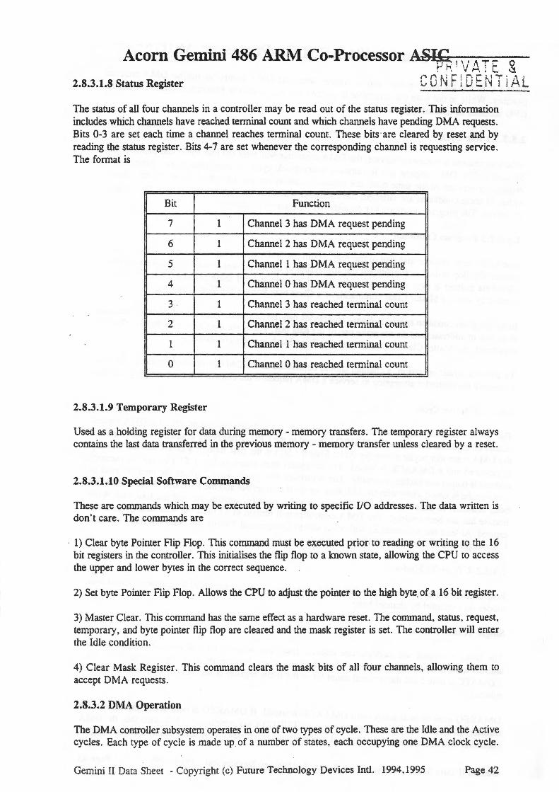
Acorn Gemini 486 ARM Co-Processor A.s~q , \ i ,.., T ~ 0 ; ' • .. .-\1 "- (!
2.8.3.1.8 Status Register C 0 N F ; D E r~ T i .A L
The status of all four channels in a controller may be read out of the status register. This infonnation includes which channels have reached tenninal count and which channels have pending DMA requests . Bits 0-3 are set each time a channel reaches tenninal count. These bits ·are cleared by reset and by reading the status register. Bits 4-7 are set whenever the corresponding channel is requesting service . The fonnat is
Bit Function
7 1 Channel 3 has DMA request pending
6 1 Channel 2 has DMA request pending
5 1 Channel 1 has DMA request pending
4 1 Channel 0 has DMA request pending
3 1 Channel 3 has reached tenninal count
2 1 Channel 2 has reached tenninal count
1 1 Channel 1 has reached tenninal count
0 1 Channel 0 has reached tenninal count
2.8.3.1.9 Temporary Register
Used as a holding register for data during memory- memory transfers. The temporary register always contains the last data transferred in the previous memory - memory transfer unless cleared by a reset.
2.8.3.1.10 Special Software Commands
These are commands which may be executed by writing to specific 110 addresses. The data written is don 't care. The commands are
1) Clear byte Pointer Flip Flop. This command must be executed prior to reading or writing to the 16 bit registers in the controller. This initialises the flip flop to a known state, allowing the CPU to access the upper and lower bytes in the correct sequence.
2) Set byte Pointer Flip Flop. Allows the CPU to adjust the pointer to the high byte. of a 16 bit register.
3) Master Clear. This command has the same effect as a hardware reset. The command, starus , request , temporary, and byte pointer flip flop are cleared and the mask register is set. The controller will enter the Idle condition.
4) Clear Mask Register. This command clears the mask bits of all four channels, allowing them to accept DMA requests .
2.8.3.2 DMA Operation
The DMA controller subsystem operates in one of two types of cycle. These are the Idle and the Active cycles . Each type of cycle is made up of a number of states , each occupying one DMA clock cycle.
Gemini II Data Sheet -Copyright (c) Future Technology Devices Inti. 1994.1995 Page 42

. EEJ,VATE & Acorn Gemini 486 ARM Co-Processor~~ 0 EN T 1 A L
State I ( SI ) is the inactive state and is entered when the DMA controller has no DMA requests pending. While in this state the controller is inactive but may enter the Program condition when the CPU accesses its internal registers.
2.8.3.2.1 Idle Cycle
When no channel is requesting service , the DMA controller will enter the Idle cycle and perform only SI states. The DMA request pin is sampled every clock cycle to determine if any peripheral is requesting service. At the same time , the controller checks for any attempted access by the CPU . If either of these conditions are satisfied, the controller will enter the Active condition or the Progran1 condition. The program condition has priority over the active condition.
2.8.3.2.2 Program Condition
Due to the large number and size of the registers in the DMA controller subsystem. an internal by1e pointer flip flop is used to supplement the addressing of the 16 bit word count and address registers . This byte pointer is used to determine the upper or lower byte of these registers. This flip flop is cleared by reset , a Master Clear command, or a Clear byte Pointer flip flop command.
In the program condition special software commands may be executed. These commands are decoded from sets of addresses and do not make .use of the data bus . These are the Clear byte Pointer flip flop command, the Master Clear command and the Clear Mask register command.
To prevent erratic operation, a channel should be masked or the DMA controller should be disabled to prevent the controller attempting to service a DMA request if the channel has not been programmed .
2.8.3.2.3 Active Cycle.
The DMA controller subsystem enters the Active cycle if a software request occurs or a DMA request occurs on an unmasked channel. CPUHRQ is issued to the CPU. After being granted control of the bus the DMA controller begins a transfer cycle . State 0 ( SO) is the first state of a DMA service . Priority is resolved and a DMAACK is issued . The controller then enters State 1 ( Sl .) where the memory address is output and latched internally . The controller then enters State 2 where the memory read or write strobe is issued along with the 1/0 write strobe if appropriate and the Extended Write feature has been enabled . In State 3 ( S3 ) the 110 write strobe rs issued if appropriate and the Extended Write feature has not been enabled. The DMA controller will remain in S3 until the wait state counter has expired. At least one additional S3 will occur unless Compressed Timing has been selected ( see later ). Subsequent transfers begin in S2.
2.8.3.2.4 Transfer Modes
Four transfer modes are supported . The DMA controller can be programmed to operate in one of these modes on a channel by channel basis .
Single Transfer Mode
The DMA controller will perform one transfer only. The word count will be decremented and the address incremented or decremented . When the word count decrements from 0000 hex to FFFF hex , a DMATC is issued and the terminal count bit in the status register is set. Auto-Initialise will occur if selected.
DMAREQ must be held active until DMAACK is issued . If DMAREQ is held active throughout the transfer, CPUHRQ will be made inactive. Once CPUHLDA has gone inactive following this, the DMA controller will again assert CPUHRQ and execute another transfer on the same channel unless a higher
Gemini II Data Sheet -Copyright (c) Future Technology Devices Inti. 1994 ,1995 Page 43

PRIVATE & Acorn Gemini 486 ARM Co-Processor AS!WFJDENTIAL
priority request has been received. In this way, single transfer mode ensures at least one full CPU cycle between transfers.
Block Transfer Mode
The DMA controller subsystem begins transfers in response to either a DMAREQ or a software ·request. DMAREQ need only to stay active until DMAACK is issued. Transfers continue until the word count decrements from 0000 hex to FFFF hex, when a DMATC is issued and the terminal count bit of the status register is set. Auto-Initialisation occurs if enabled.
Demand Transfer Mode
Transfers begin on the assertion of DMAREQ and continue until terminal count is reached or DMAREQ is de-asserted. This mode may be used by 110 devices with a limited buffering capacity. The device may initiate a transfer, continuing until its buffer capacity is exhausted. It may then re-establish transfers by re-asserting DMAREQ.
In the time be ween services, the CPU is allowed to operate. The CPU can, if desired. monitor the progress of th operation by reading the intermediate values of word count and address registers. \Vhen DMAREQ is e-asserted , higher priority channels are allowed service.
Reaching te inal count results in DMATC being issued and the terminal count bit in the status register is set. Auto-1 itialisation occurs if enabled.
In Cascade ode, DMAACK is returned in response to DMAREQ. No DMA transfer takes place and the DMA co troller does not issue any commands on the bus. An externaliiO Channel Bus Master can thus take co rol of the 110 Channel by using a spare DMA channel programmed in cascade mode to gain control f the bus , then asserting the MASTER# signal to turn the 110 channel bus buffers around thus enablin the Bus Master to drive the system.
2.8.3.2.5 T ansfer Types
The three t ansfer types are Read, Write, and Verify transfers. Single transfer mode, block transfer mode and d mand transfer mode can perform any of the three transfer types.
This trans£ r moves data from an l/0 device to memory by activating the 110 read and the memory and strobes during the same transfer.
This trans er moves data from memory to an 110 device by activating the 110 write and the memory read co and strobes during the same transfer .
The com oller operates as in a read or write transfer but does not generate the memory and 110 command strobes.
Memory - Memory Transfer
Gf'mini II Data Sheet - Copyright (c) Future Technology Devices Intl. 1994.1995 Page 44

Acorn Gemini 486 ARM Co-Processor J.~IVD-1~~~~- L An additional transfer mode exists which uses channels 0 and 1 to provide a block move of memory from one address space to another. Programming bit 0 in the DMA Command Register selects channels 0 and 1 to operate as memory - memory transfer channels. The transfer is initiated by setting the software DMA request for channel 0.
The channel 0 current address register provides the address for the source block and is incremented or decremented as usual. The data byte read is stored in the internal Temporary Register. Channel 1 then transfers this data from the temporary register to memory using the address in its Current Address register. This address is incremented or decremented in the normal manner. The channel 1 Word Count is decremented and transfers are terminated when terminal count is reached .
Channel 0 may be programmed to retain the same address for all transfers via bit 1 of the conm1and register, allowing a single word to be written to a block of memory .
2.8.3.2. 7 Auto Initialisation
By setting bit 4 in the Mode Register for a DMA channel, that channel may be programmed to be an Auto Initialise channel. The original values of the Current Address and Current Word Registers are restored from the Base Address and Base Word Count registers afterreaching terminal count. The base registers are loaded simultaneously with the current registers during programming and remain unchanged during DMA operation.
On an auto-initialise channel, the request mask bit is not cleared at terminal count allowing another DMA service request to be handled without CPU intervention. . Both word counts should be programmed identically for memory- memory transfers.
2.8.3.2.8 Address Generation
The DMA controller subsystem generates a 24 bit memory address for DMA transfer cycles. For DMA8, address bits A0-15 are generated by the DMA controller and A16-23 come from the LS612 compatible page registers (bits 0-7 ). For DMA16, address bit AO is low, A1-16 are generated by the DMA controller and A17-23 come from the page registers ( bits 1 - 7 ).
The 74LS612 compatible page registers are a set of 8 bit registers which are used to generate the high order memory addresses during DMA transfers. Each DMA channel has a page register. associated with it, with the exception of channel 0 of DMA16 which is used for internal cascading to DMA8 .
The assignment of these page registers to the DMA channels is as follows -
110 Address (hex) Type Function
080 Read/Write Unused
081 Read/Write DMA8 Channel 2
082 Read/Write DMA8 Channel 3
083 Read/Write DMA8 Channel 1
084 Read/Write Unused
085 Read/Write Unused
086 Read/Write Unused
Gemini II Data Sheet -Copyright (c) Future Technology Devices Inti. 1994,1995 Page 45

1/0 Address (hex) Type Function
087 Read/Write DMA8 Channel 0
088 Read/Write Unused
089 Read/Write DMA 16 Channel 2
08A Read/Write DMA16 Channel 3
08B Read/Write DMA16 Channel 1
08C Read/Write Unused
080 Read/Write Unused
08E Read/Write Unused
08F Read/Write DRAM Refresh Cycle
Only 8 of the page registers are used, the others are included to maintain PC-AT compatibility .
2.8.4 Port B register
To maintain PC-AT compatibility , the ASIC provide·s the logic for the Port B Register at I/0 address 061 hex. There is no mechanism for generating -NMis (there is no memory parity and the IOCHK signal on the ISA bus will be ignored) .
GP.mini II Data Sheel -Copyright (c) Futur~ Technology Devices Inti. 1994 ,1995 Page 46

Acorn Gemini 486 ARM Co-Processor ASIC ----------~~~~
P R I \ I ,, T ,.-t s I i li h I ~
r- r ~ ! ~ 1 n c r-J T \ t:. i \_.I ;.,_ ' . , : l ~ :....... : 1 : I . . .:::.
Bit assignments for the Port B Register are -
Bit Function
7 Unused- read back as 0
6 Unused- read back fS 0
5 Reflects the state of output 2 from the timer/counter subsystem. Read only
4 Refresh detect - toggles with each refresh request. Read only
3 Unused.
2 Unused.
1 Speaker. Read I write . Cleared by reset
1 Enable speaker data onto SPKR output
0 Disable
0 GATE2 - gate input to timer/counter 2 . Read I write. Cleared on reset
1 Count enable
0 Count disable
2.8.5 8042 Keyboard Simulator
Command and data accesses to ports 60h and 64h are trapped and the appropriate A20GATE and FastReset signa)s are generated. These accesses are also passed through to the mailbox logic for ARM keyboard simulation. The ARM may disable the keyboard simulator and generate A20GATE and FastReset signals itself- refer to Miscellaneous Control Register (MISCR) section for details .
2.8.6 Numeric Co-processor Interface
An I/0 write to port OFOh resets an FPU busy flip-flop and an I/0 write to port OF1 generates an FPU reset for compatibility with PC-AT architecture.
2.9 FIFO
A 16 level deep FIFO is provided to improve performance by allowing the buffering of write data to the DRAM. Address se~ing of the FIFO data allows the 486 CPU to read from the ARM bus, unless the read address is contained in the write FIFO, in which case the 486 CPU has to wait until the FIFO has emptied before reading data from the ARM bus.
Gemini II Data Sheet -Copyright (c) Future Technology Devices Inti. 1994,1995 Page 47
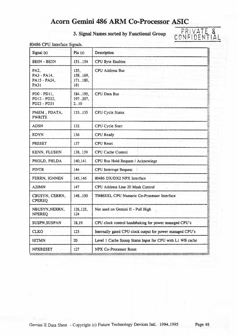
Acorn Gemini 486 ARM Co-Processor ASIC
3. Signal Names sorted by Functional Group PRiV ATE & CO NF I DE NTI .Al
80486 CPU Incerface Signals.
Signal (s) Pin (s) Description
BEON- BE3N 151..154 CPU Byte Enables
PA2, 155, CPU Address Bus PA3- PA14 , 158 .. 169, PA15- PA24, 171..180, PA31 181
PDO- PO l l, 184 .. 195, CPU Data Bus PD1 2 - PD22, 197 .. 207 , PD23 - PD31 2 .. 10
PMEM , PDATA, 133 .. 135 CPU Cycle Status PWRITE
ADSN 132 CPU Cycle Start
RDYN 136 CPU Ready
PRESET 137 CPU Reset I KEN , FLUSHN 138, 139 CPU Cache Control I PHOLD, PHLDA 140, 141 CPU Bus Hold Request I ~cknowlege PINTR 144 CPU Interrupt Request I FERRN, IGNNEN 145, 146 80486 DX/DX2 NPX Interface
A20MN 147 CPU Address Line 20 Mask Control
CBUSYN, CERRN, 148 . . 150 TI486SXL CPU Numeric Co-Processor Interface CPEREQ
NBUSYN,NERRN, 126, 125, Not used on Gemini II - Pull H~gh NPEREQ 124
SUSPN ,SUSPAN 18,19 CPU clock control handshaking for power managed CPU 's
CLKO 123 Internally gated CPU clock output for power managed CPU's
HITMN 20 Level 1 Cache Snoop Status Input for CPU with Ll WB cache
NPXRESET 127 NPX Co-Processor Reset
Gemini II Data Sheec - Copyright (c) Future Techno logy Devices Incl. 1994,1995 Page 48

A G . "486ARMC Pr A-~~IVATE & corn ennn1 o- ocessor ~~ 1 DENT l A L
Level 2 Cache Interface Signals. r---------------.--=-----r--------------------------~----------------~~
~ Signal (s) Pin (s) Description ~ r---------------+--------1---------------------------------------------~~
~ TDO- TD7 31..38 Tag SRAM Data Bus ~ r---------------+--------1---------------------------~----------------~~
~ TWEN 30 1----------------+--------1--T-ag __ S_RA __ M __ W_r_it_e_E_n_ab_l_e __________________________ ~~
~ ~ ~ CWEAN, CWEBN, 23,24, Cache SRAM Write Enables CWECN. CWEDN 25,28
~ ~ ~ 1----------------+--------l---------------------------------------------~-~
COEN 29 :~
Cache SRAM Output Enable ~
r---------------+--------r--------------------------------------------~m CA2,CA3 21,22 Cache SRAM Low Addr Bits
~
.. ,.,.,. :;;;;;:;:::;;,~:~;'';:,;;;'"'\'""';;;;',;;;;;;;;;;;,;,;,,,,;;,:;::1 ARM Co-Processor Interface Signals .
Signal (s) Pin (s) Description
AAO- AA3, 88 .. 91, ARM CPU Address Bus AA4- AA14, 93- 103, AA15- AA25 , 106 . . 116,
I AA26- AA28 118 .. 120
ADO- AD11, 40 .. 51, ARM CPU Data Bus AD12- AD23, 54 . . 65 ,
I AD24- AD31 67 .. 74 I
MCLKI 80 ARM Memory Clock I
NRW 86 ARM Read/Write Cycle Status !
NBW 85 I
ARM Byte/Word Select
NMREQ 76 ARM Memory Request
NPREQ 77 ARM 486 Co-Processor Bus Request
DBE 75 ARM Data Bus Enable
ABE 84 ARM CPU Bus Enable I NRESET 81 System Reset
NWAIT 87 ARM CPU Wait Request
LOCK 121 ARM CPU Locked Cycle Status
NPIRQ 83 ARM 486 Co-Processor Maskable Interrupt
NPFIQ 82 ARM 486 Co-Processor Non-Maskable Interrupt
Gemini II Data Sheet -Copyright (c) Future Technology Devices Inti. 1994,1995 Page 49

Acorn Gemini 486 ARM Co-Processor t!rW1~11)- 1i ~ Miscellaneous Signals . r---------~~--.-------.--------------------------------------------~
~ Signal (s) Pin (s) Description ~
~--------------r-------+--------------------------------------------~ ~ CLKIN 129 33/66MHz Input Clock ~
~--------------r-------+--------------------------------------------~ CLK14M 142 14.318MHz Timer Clock ~
~ ~--------------r-------+--------------------------------------------~
~ OSPK 11 PC Speaker Output ~ r---------------r-------+--------------------------------------------~
122 1 = 1x CPU clock input CPU , 0 = 2x CPU clock input ~: CPUSEL t---------------t-------+--------------------------------------------M
~:;::
s:~ MSTRN 12 Tie low on Gemini II
:~~is.I 6 , Reserved I No-Connect Pins I (N.C.)
t----------t-1_7 __ -t---------------------'il'j vee ASIC +5v POWER PIN
.·.;:: :;:;:· .·.;::
iii! f~~
27,52,79, 104, 131 , 157,183 , 208
t---------------+--------+------------------------------------------'::::i GND 1, 13,26,
39 ,53,66, 78,92,
ASIC Ov POWER PIN
105 ' 117' ~~1j1~ 130 14-"t ·:·:·: . .) , :;:::
157,170, :::::: 182,196 ..
;:;:;:;:;:;:;:;:;:;:;:;:;:;:;:;:;:;:;~:;:;:::::::::::::::::::::::::::;:;:;:::;:;:;:::::::::::;:;::::::::~::::::::::::~:::;::::::::~:::::::::::~;:;:;::~:;:;:;:;:;:;:;:::::::::;:;:;:;:;:;:;:::::: : ::;:;:::::;:::::::;:;:::::::::;:;:;:;:;:;:::::;:;:;:;:;:;:;:;:;:;:;:;:;:;:;:;:;:;:;:;:;:;:::;:;:::::::;:;:;:;:;:;:;:;:;:;:;:;:;:::::;:;:;:;:;:;:;:;:::::::::::::::::::::::::~:::::::::::::::::::::::::::::::::~:::::;~::::::::::::;:::::~:;::::~~==::::::::::::::::i~~~jj
Gemini II Data Sheet -Copyright (c) Furure Technology Devices Inti. 1994,1995 Page 50

Acorn Gemini 486 ARLVI Co-Processor ASIC
4. Signal Names sorted by Pin Number ~;) i' :/\ Tt- c I I \ I ... ,....... I 6!.
r· n ~. : ;:: ' r1 c ~.: : ! :"' i '-· - · ' 1 ! : :... L. ! , I j ,•~ ~
Pin I Signal Name Pin I Signal Name Pin I Signal Name Pin I Signal Name
1 GND 53 GND 105 GND 157 GND
2 PD23 54 AD12 106 AA15 158 PA3
3 PD24 55 AD13 107 AA16 159 P.-\4
4 PD25 56 AD14 108 AA17 160 PAS
5 PD26 57 AD15 109 AA18 161 PA6
6 PD27 58 AD16 110 AA19 162 P.-\7
7 PD28 59 AD17 111 AA20 163 PAS
8 PD29 60 AD18 112 AA21 164 PA9
9 PD30 61 AD19 113 AA22 165 PAlO
10 PD31 62 AD20 114 ' AA23 166 PAll
11 OSPK 63 AD21 115 AA24 167 PA12
12 MSTRN 64 AD22 116 AA25 168 PA13
13 GND 65 AD23 117 GND 169 PA14
14 N.C. 66 GND 118 AA26 170 GND
15 N.C. 67 AD24 119 AA27 171 PAlS
16 N.C. 68 AD25 120 AA28 172 PA16
17 N.C . 69 AD26 121 LOCK 173 PA17
18 SUSPN 70 AD27 122 CPUSEL 174 PA1 8
19 SUSPAN 71 AD28 123 CLKO 175 PA19
20 HITMN 72 AD29 124 NPEREQ 176 PA20
21 CA2 73 AD30 125 NERRN 177 PA21
22 CA3 74 AD31 126 NBUSYN 178 PA22
23 CWEAN 75 DBE 127 NPRESET 179 PA23
24 CWEBN 76 NMREQ 128 N.C. 180 PA24
25 CWECN 77 NPREQ 129 CLKIN 181 PA31
26 GND 78 GND 130 GND 182 GND
Signal Names sorted by Pin Number ctd . . .
Gemini II Data Sheet -Copyright (c) Future Technology Devices Intl. 1994,1995 Page 51

Acorn Gemini 486 ARM Co-ProcessorA..-4.,:AIU..SLLI_C'-..___ __
Pin I Signal Name Pin I Signal Name Pin I Signal Name Pin I Signal Name
27 vee 79 vee 131 vee 183 vee
28 CWEDN 80 MCLK.l 132 ADSN 184 PDO
29 COEN 81 NRESET 133 PMEM 185 PD1
30 TWEN 82 NPFIQ 134 PDATA 186 PD2
31 TDO 83 NPIRQ 135 PWRITE 187 PD3
32 TD1 84 ABE 136 RDYN 188 PD4
33 TD2 85 NBW 137 PRESET 189 PD5
34 TD3 86 NRW 138 KENN 190 PD6
35 TD4 87 NWAIT 139 FLUSHN 191 PD7
36 TDS 88 AAO 140 PH OLD 192 PD8
37 TD6 89 AA1 141 PHLDA 193 PD9
38 TD7 90 AA2 142 CLK14M 194 PD lO
39 GND 91 AA3 143 GND 195 PD 11
40 ADO 92 GND 144 PINTR 196 GND
41 AD1 93 AA4 145 FERRN 197 PD12
42 AD2 94 AAS 146 IGNNEN 198 PD13
43 AD3 95 AA6 147 A20MN 199 PD14
44 AD4 96 AA7 148 CBUSYN 200 PD15
45 ADS 97 AA8 149 CERRN 201 PD16
46 AD6 98 AA9 150 CPEREQ 202 PD17
47 AD7 99 AA10 151 BEON 203 PD18
48 AD8 100 AA11 152 BElN 204 PD 19
49 AD9 101 AA12 153 BE2N 205 PD20
50 AD10 102 AA13 154 BE3N 206 PD21
51 AD11 103 AA14 155 PA2 207 PD22
52 vee 104 vee 156 vee 208 vee
r:Q.,., ;" ; n n:~r~ Sheer -Copyright (c) Furure Technology Devices Inti. 1994,1995 Page 52

Acorn Gemini 486 ARM Co-Processor ASIC
PRIVATE g . CONF IDENTI ,AL
30.6
28.0 t---------- - - -------------------··
25.5
-------···-·--··
- · 11.25 --- "-------·-···-----
~ -·-- -----~~ -- --·- --- --~-----= - --------~~~~~---- .. - - - - - - - - - - - - - - - .. , - - - - - - - - - - - - - -' :..; - -· _. - - - - - - - - - - - - - - - ---------- ···-··-- ----- --------- - --~~~L --- ~-- - ----
1.25 0.23 0.5 1.3
MAX
0.1 0 .5
3.4 NOM
ALL DIMENSIONS IN MILLIMETRES 0.25 MIN
5. 208 Pin PQFP Package Dimensions
Gemini II Data Sheet - Copyright (c) Future Technology Devices Inti. 1994,1995 Page 53