general article how do wings generate lift?
TRANSCRIPT
GENERAL ARTICLE
How Do Wings Generate Lift?1. Popular Myths, What They Mean and Why They Work
M D Deshpande and M Sivapragasam
M D Deshpande is a Professor
in the Faculty of Engineering
and Technology at M S
Ramaiah University of
Applied Sciences.
M Sivapragasam is an
Assistant Professor in the
Faculty of Engineering and
Technology at M S Ramaiah
University of Applied
Sciences.
How lift is generated by a moving wing is understood sat-isfactorily. But the rigorous explanation requires elaboratetheoretical background, and hence there are many simplerexplanations in the popular literature. In the first part of thisarticle, some such popular models are discussed after brieflydealing with some required preliminary ideas. The conclud-ing part of the article will deal with some simple quantitativemodels and then tie up many of these simple ideas and propo-sitions together to the rigorous momentum conservation prin-ciple placing these popular models in perspective.
So how do you go about teaching them something new? By mix-ing what they know with what they don’t know. Then, when theysee in their fog something they recognise they think, “Ah I knowthat!” And then it is just one more step to “Ah, I know the wholething.” And their mind thrusts forward into the unknown and theybegin to recognise what they didn’t know before and they increasetheir powers of understanding.
Picasso
1. Introduction
A wing that is moving forward in a fluid generates lift. The wingcan be a flat plate at incidence or a cambered plate (see Box 1).Even after knowing much about the theory of flight, it is difficultnot to be impressed when looking at a heavy transport aircraft andwondering that it really does fly. The theory of flight has caught Keywords
Airfoil, Bernoulli’s principle, vis-
cosity, streamline curvature, vor-
ticity, irrotational flow.
the imagination of the general public, and hence needs simple ex-planation. It is inevitable that there are many such explanationsleading to discussions and objections. This article is meant to dis-
RESONANCE | January 2017 61

GENERAL ARTICLE
cuss such models which are approximationsIt is a good idea to agreefirst on what is an
acceptable model. Sincewe are in the realm of
classical mechanics wecan start with Newton’ssecond law of motion.
of a rigorous theory,and to see how they are connected and can be made acceptable.
It is a good idea to agree first on what is an acceptable model.Since we are in the realm of classical mechanics we can start withNewton’s second law of motion. Hence if a wing can generate liftequal to its weight (total weight of the vehicle) it can balance thegravitational pull and can maintain level flight. The equationsfor fluid flow that are equivalent to the second law are the well-known Navier–Stokes (N–S) equations [1]. These equations havebeen known for nearly two centuries. But it is not easy to inferfrom these equations that a wing develops lift since these are a setof coupled non-linear partial differential equations. They were, infact, solved only for some simple geometries till the second halfof the 20th century.
The advent of digital computers made it possible to compute flowaround arbitrarily shaped bodies. But there is a difficulty in suchan approach. We can solve the N–S equations using a computerfor a given geometry but drawing a general inference like, a cam-bered plate in a flow generates lift, or, an increase in camberleads to increased lift, has to be done only through a parametricstudy (see Box 1). This parametric study involves several param-eters like wing geometry involving camber and size, angle of at-tack, flow velocity, etc. This is neither a convenient method norof interest to a general reader who wants to know how lift is gen-erated, and this is where simple theories giving an explanationhave a role to play.
The difficulties mentioned in the previous paragraph may be ap-preciated further by a quotation from 1895, “Heavier-than-air fly-ing machines are impossible”, which is attributed to an accom-plished scientist like Lord Kelvin, then the President of the RoyalSociety. A keen observer like Otto Lilienthal, a contemporary ofthe Wright brothers, who built gliders, and was trying to buildheavier than air flying machines wrote a remarkable book basedon his observations on bird flight and experiments [2]. However,his concept of lift (to be interpreted here as upward force) de-pended solely on the drag of a plate moving in a direction
62 RESONANCE | January 2017

GENERAL ARTICLE
Box 1. Lift and Drag Forces
A flat plate inclined at an angle α to the flow as shown in the left frame, or a cambered plate as shown in the
right frame are subjected to a force R. The component of the force perpendicular to free stream velocity u∞is defined as lift L and the component of force along u∞ is defined as drag D. Note that a plate stationary in
a uniform flow, or a plate moving uniformly in a stationary fluid are equivalent.
∞
α
D
u
LR
∞
R
u
L
D
(a) (b)
Figure A. Schematic illustration of lift, L and drag, D forces on (a) An inclined flat plate and (b) A
cambered plate. R is the resultant force.
perpendicular to its plane (see Box 1). Hence a horizontal platemoving down vertically develops lift (this is actually drag but act-ing upwards and hence helps to lift the body). Obviously, Lilien-thal was inspired by the flight of birds. The modern idea of lift, onthe other hand, is based on an inclined plate, which may be flator cambered, moving forward. Note that Lilienthal was work-ing almost a hundred years after Sir George Cayley.1 1See https:en.wikipedia.org
/wiki/George Cayley for his
interesting biography.
He drew in1799, the lift–drag vector diagram and flat plate wing at an angleof attack to the relative wind (Figure 1). In the right frame, a thinplate inclined to the direction of the flow is shown along with theoncoming velocity vector. Apart from this modern representationof forces, hidden here is the concept that flapping is not requiredto generate lift. Further, the resultant force is shown correctlybeing perpendicular to the plate, and decomposed into two com-ponents – lift and drag. The lift force is perpendicular to the flowand probably given more prominence with an arrowhead. The leftframe shows an airship with a boat like fuselage and curved fixedwing. At the rear of this machine we see a long rudder and two
RESONANCE | January 2017 63

GENERAL ARTICLE
Figure 1. Silver disc show-
ing lift and drag inscribed by
Sir George Cayley. (Source:
http:/www.ctie.monash.edu.
au/hargrave/cayley.html).
pilot-operated propulsive flappers. Thus, the propulsive system isuncoupled from lift generation. There is no sign of flapping ofthe wing.
2. Fluid Mechanics Preliminaries
2.1 Bernoulli’s Principle
The explanations in this article involve the use of Bernoulli’s prin-ciple, and hence it is briefly summarised here. See [3, 4] for de-tails. We have mentioned that a wing can be stationary in a flowand still generate lift. The wing kept in the fluid with uniform flowdisturbs the fluid motion leading to streamline distortion. SinceBernoulli’s principle relates velocity to pressure at any point on agiven streamline (see Box 2) it is quite handy. It is sufficient hereto restrict to incompressible, steady flow, since it makes analysismuch simpler in the present context. The principle is obtainedby integrating the momentum equation along a streamline for aninviscid flow. Then we have,
p +12ρu2 + ρgz = constant. (1)
Here p is the pressure, u is the velocity magnitude, ρ is the fluiddensity, g is the acceleration due to gravity and z is the height ofthe point on the streamline above a reference level. The constantof integration on the RHS of (1) is assigned to a streamline andhence can vary from one streamline to the other. However, it canbe proved that in an irrotational flow (see Box 3) it has the samevalue in the whole field. This observation will be useful later.
64 RESONANCE | January 2017

GENERAL ARTICLE
Box 2. Streamlines
A streamline is a curve in the flow such that the tangent to it at any point is the direction of the velocity
at that point. If the flow is steady, the streamline is also the particle path. In a steady, two-dimensional,
incompressible flow, if the streamlines are getting closer, as shown in the left frame, the velocity has to
increase in the flow direction. In a flow, if the streamlines are all parallel straight lines they represent a
constant velocity on each streamline.
(a) (b)
Figure A. (a) Curved streamlines and (b) Parallel streamlines.
2.2 Role of Viscosity
Viscosity plays an important and interesting role in the motionof fluids. Difficulty in modelling this role slowed the progress inarriving at the N–S equations even after the field equations gov-erning the inviscid flow (Euler equations) were known. Viscous
Box 3. Vorticity and Irrotational Flow
Vorticity is defined as the curl of velocity V and hence it is a vector.
VorticityΩ = � × V
In a two-dimensional flow in the x-y plane, only the z-component of vorticity Ωz is non-zero and is given
by the expression Ωz = (∂v/∂x) − (∂u/∂y), where (u, v) are the (x, y) velocity components. A flow is
irrotational in a region if vorticity in that region is zero. In ideal or inviscid flows, vorticity cannot be
created and hence an irrotational flow remains irrotational. In the presence of a body, because of the effect
of viscosity, vorticity is generated near the wall and transported away, especially in the wake.
RESONANCE | January 2017 65
GENERAL ARTICLE
Box 4. The Euler and the Navier–Stokes Equations
Newton’s second law of motion applied to a fluid element leads to the Euler equations if the stresses due
to viscosity are neglected [1]. These form a system of three (one for each direction) first order non-linear
partial differential equations. If the stresses due to viscosity are also included, we get the Navier–Stokes (N–
S) equations. The dependent variables in these equations are the velocity components (u, v,w), fluid density
ρ and pressure p. Since there are five dependent variables (u, v,w, ρ, p) in the Euler (or N–S) equations, we
need in addition to these three equations, two more equations in the form of mass and energy conservation.
In incompressible flow, since ρ is a known constant, we need only the mass conservation equation.
stressesThe complex nature ofthe N–S equations did
not permit this drag to becalculated even for thesimplest of bodies − a
flat plate of zerothickness at zero angle
of attack.
depend on spatial velocity derivatives, and addition ofthe viscous terms to the Euler equations increases the order of thepartial differential equations from one to two (see Box 4). Thisneeds an extra boundary condition which is provided by the no-slip or tangential velocity being zero boundary condition on thewall (wing surface) in addition to the no-penetration or normalvelocity being zero condition.
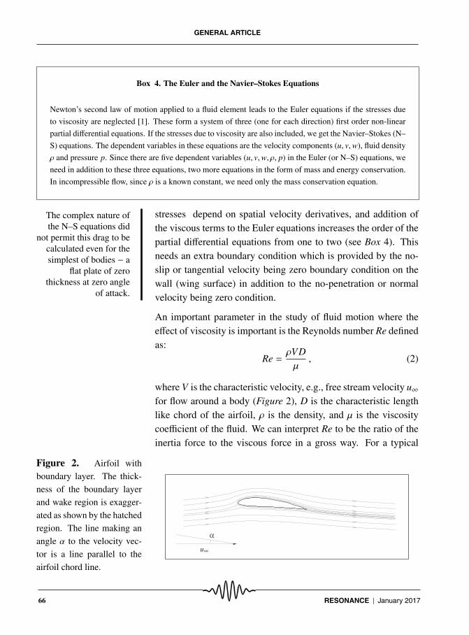
An important parameter in the study of fluid motion where theeffect of viscosity is important is the Reynolds number Re definedas:
Re =ρVDμ
, (2)
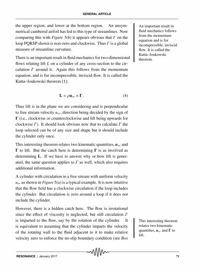
where V is the characteristic velocity, e.g., free stream velocity u∞for flow around a body (Figure 2), D is the characteristic lengthlike chord of the airfoil, ρ is the density, and μ is the viscositycoefficient of the fluid. We can interpret Re to be the ratio of theinertia force to the viscous force in a gross way. For a typical
Figure 2. Airfoil with
boundary layer. The thick-
ness of the boundary layer
and wake region is exagger-
ated as shown by the hatched
region. The line making an
angle α to the velocity vec-
tor is a line parallel to the
airfoil chord line.
α
u∞
66 RESONANCE | January 2017

GENERAL ARTICLE
aircraft wing, Re is of the order of several millions. Hence, if Reis large, it indicates that the inertia force is more dominant com-pared to the viscous force; flow behaves as though it is inviscid.However, application of no-slip boundary condition warrants thata large change in velocity takes place in a thin layer called theboundary layer as indicated in Figure 2. We cannot neglect theeffect of viscosity in this layer no matter how large the Re [5].
Application of the no-slip boundary condition results in a largevelocity gradient in a rather thin region, and in a direction normalto the wall, and consequent viscous shear stress on the wall. Inte-gration of pressure and viscous stresses around the airfoil surfacegives the net force acting on the airfoil (see Box 5).
Inviscid theories admit velocity slip on the wall and viscous stress
Box 5. Forces on a Body Immersed in a Fluid
A body immersed in a fluid is subjected to forces acting on its surface. If the fluid is stationary, the only
stress acting on the surface is the pressure acting normal to the surface and acting inwards. This hydrostatic
case leads to the Archimedes buoyancy force.
If, on the other hand, there is relative motion of the fluid around the body, the pressure on the surface gets
altered and also there is tangential viscous stress τw as shown. Integration of the stresses around the whole
body gives the net force due to pressure and viscous stress. If the body was immersed in a uniform flow
with velocity far away being u∞, the force acting on the body along the flow is drag D and perpendicular to
the flow is lift L.
τ
⟨
∞
t
n
u
⟨
p
w
Figure A. Pressure, p and tangential viscous stress, τw on the wall of a body immersed in a flow.
RESONANCE | January 2017 67

GENERAL ARTICLE
to be zero. For a streamlinedThanks to digitalcomputers, we can
calculate the lift force onan airfoil using viscous
or inviscid governingequations, and smugly
state that the results arealmost the same. But
now we are in a positionto ask should not they
be?
body like an airfoil, as shown inFigure 2, this stress is nearly along the flow direction on both thesides and hence adds up to viscous drag. The complex natureof the N–S equations did not permit this drag to be calculatedeven for the simplest of bodies − a flat plate of zero thickness atzero angle of attack. In a boundary layer, the gradients along theflow direction (x-direction along the wall) are small, compared tothe gradients in the y-direction normal to the wall. Further, theboundary layer approximation reveals that the pressure gradientin the direction normal to the wall (∂p/∂y) ≈ 0, and hence one canuse the inviscid Euler equations to calculate pressure distributionon the airfoil [5].
If the boundary layer remains thin and attached to the body, wecan use the inviscid equations to get pressure distribution on thebody. This gives for inviscid, steady, two-dimensional flows zerodrag. This celebrated paradox is named after d’Alembert. Despitesuch a strange result, one can use this pressure distribution andcalculate the lift generated.
Thanks to digital computers, we can calculate the lift force on anairfoil using viscous or inviscid governing equations, and smuglystate that the results are almost the same. But now we are in aposition to ask should not they be? But this does not help us inthe present task since the inviscid equations are also quite difficultand have the same difficulty that was stated in a previous section.Then we can solve the equations for a specific case but cannotdraw general conclusions.
2.3 Circulation and Lift ∗
[∗ Though this section requires a background in vector analysis,it is recommended that readers not familiar with this area maystill read on this section to get the general ideas, and not lose thecontinuity.]
The concept of circulation will be useful in the present discus-sion. We restrict the discussion to steady, two-dimensional, in-compressible flow. Circulation Γ along a closed curve in a ve-
68 RESONANCE | January 2017
GENERAL ARTICLE
locity field is given by the line integral along this curve (see Box6),
Γ =
∮V · ds . (3)
Evaluation of Γ along a rectangular curve ABCDA in the two ve-locity fields shown in Figure 3 is instructive. In Figure 3(a), withuniform velocity field, the two sides AB and CD do not contributeto the integral since velocity is perpendicular to these sides, andcontributions along BC and DA cancel out leading to Γ = 0. Inthe sheared flow in Figure 3(b), on the other hand, values alongBC and DA do not fully cancel, leading to clockwise value of Γ,which may be assigned a negative sign. If we treat Γ as a vector,the clockwise or negative Γ is along the negative z-direction, or
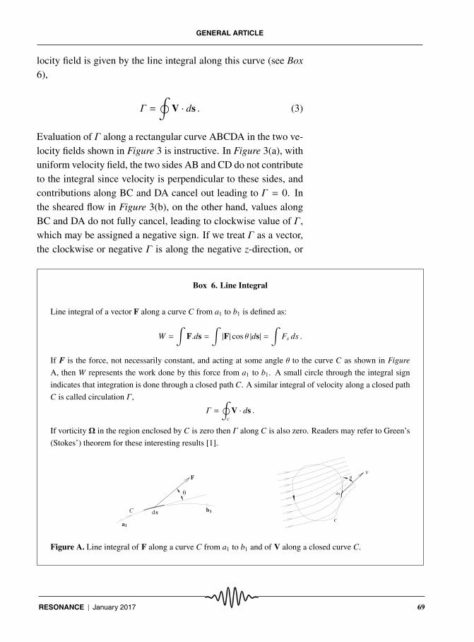
Box 6. Line Integral
Line integral of a vector F along a curve C from a1 to b1 is defined as:
W =∫
F.ds =∫|F| cos θ |ds| =
∫Fs ds .
If F is the force, not necessarily constant, and acting at some angle θ to the curve C as shown in Figure
A, then W represents the work done by this force from a1 to b1. A small circle through the integral sign
indicates that integration is done through a closed path C. A similar integral of velocity along a closed path
C is called circulation Γ,
Γ =
∮c
V · ds .
If vorticity Ω in the region enclosed by C is zero then Γ along C is also zero. Readers may refer to Green’s
(Stokes’) theorem for these interesting results [1].
a
sC
θ
b
1
1
F
d
s
θ
d
C
V
Figure A. Line integral of F along a curve C from a1 to b1 and of V along a closed curve C.
RESONANCE | January 2017 69

GENERAL ARTICLE
Figure 3. (a) Uniform flow
with a circulation loop to
show Γ = 0 and (b) Shear
flow with a circulation loop
to show non-zero Γ.
(a) (b)
DA
B C
y
x
DA
B C
Figure 4. Streamlines
around an airfoil kept in
a uniform flow. Two
loops in the flow to show
zero (loop ABCDA exclud-
ing airfoil) and non-zero Γ
(loop PQRSP around air-
foil).
B
y
C
D
QP
RS
A
x
it is perpendicular to the plane of the paper and heading inside asgiven by the right hand rule. In Figure 3(a) Γ is zero no matterhow big the rectangle is, and, in fact, it is zero irrespective of theshape of the loop. This is because the flow is uniform in this fig-ure and it can be generalised further: If the flow is irrotational,i.e., vorticity Ω = � × V is zero inside the loop everywhere, thenΓ = 0.
Now consider flow around an airfoil at a low angle of attack asshown in Figure 4. This may be a cambered airfoil or even asymmetrical airfoil at incidence. If the flow is at a sufficientlyhigh Reynolds number, effect of viscosity is restricted to the thinboundary layer and the thin wake, and outside this region, theflow may be considered to be irrotational. Then Γ is zero aroundthe loop ABCDA shown. In fact, it is zero around any loop thatdoes not enclose the airfoil and the boundary layer including thewake. The loop PQRSP, on the other hand, encloses the rotationalflow and hence Γ is non-zero. By looking at the spacing betweenthe streamlines, it can be noted that velocity is higher than u∞ at
70 RESONANCE | January 2017
GENERAL ARTICLE
the upper region, and lower at the bottom region. An important result influid mechanics followsfrom the momentumequation and is forincompressible, inviscidflow. It is called theKutta–Joukowskitheorem.
An unsym-metrical cambered airfoil has led to this type of streamlines. Nowcomparing this with Figure 3(b) it appears obvious that Γ on theloop PQRSP shown is non-zero and clockwise. Thus Γ is a globalmeasure of streamline curvature.
There is an important result in fluid mechanics for two-dimensionalflows relating lift L on a cylinder of any cross-section to the cir-culation Γ around it. Again this follows from the momentumequation, and is for incompressible, inviscid flow. It is called theKutta–Joukowski theorem [1]:
L = ρu∞ × Γ . (4)
Thus lift is in the plane we are considering and is perpendicularto free stream velocity u∞, direction being decided by the sign ofΓ (i.e., clockwise or counterclockwise and lift being upwards forclockwise Γ). It should look obvious now that to calculate Γ theloop selected can be of any size and shape but it should includethe cylinder only once.
This interesting theorem relates two kinematic quantities, u∞ andΓ to lift. But the catch here is determining Γ is as involved asdetermining L. If we have to answer why or how lift is gener-ated, the same question applies to Γ as well, which also requiresadditional information.
A cylinder with circulation in a free stream with uniform velocityu∞ as shown in Figure 5(a) is a typical example. It is now intuitivethat the flow field has a clockwise circulation if the loop includesthe cylinder. But circulation is zero around a loop if it does notinclude the cylinder.
However, there is a hidden catch here. The flow is irrotationalsince the effect of viscosity is neglected, but still circulation Γis imparted to the flow, say by the rotation of the cylinder. This interesting theorem
relates two kinematicquantities, u∞ and Γ tolift.
Itis equivalent to assuming that the cylinder imparts the velocityof the rotating wall to the fluid adjacent to it to make relativevelocity zero to enforce the no-slip boundary condition (see Box
RESONANCE | January 2017 71
GENERAL ARTICLE
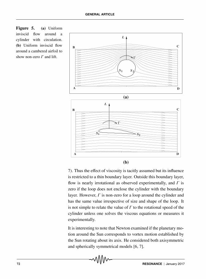
Figure 5. (a) Uniform
inviscid flow around a
cylinder with circulation.
(b) Uniform inviscid flow
around a cambered airfoil to
show non-zero Γ and lift.
B
S
D
C
Γ
2S1
A
L
(a)
B
S
D
C
L
Γ
2
A
S1
(b)
7). Thus the effect of viscosity is tacitly assumed but its influenceis restricted to a thin boundary layer. Outside this boundary layer,flow is nearly irrotational as observed experimentally, and Γ iszero if the loop does not enclose the cylinder with the boundarylayer. However, Γ is non-zero for a loop around the cylinder andhas the same value irrespective of size and shape of the loop. Itis not simple to relate the value of Γ to the rotational speed of thecylinder unless one solves the viscous equations or measures itexperimentally.
It is interesting to note that Newton examined if the planetary mo-tion around the Sun corresponds to vortex motion established bythe Sun rotating about its axis. He considered both axisymmetricand spherically symmetrical models [6, 7].
72 RESONANCE | January 2017

GENERAL ARTICLE
Box 7. Streamlines Around a Rotating Cylinder
A rotating cylinder immersed in a flow from left to right imparts momentum to the adjacent fluid and sets
it in motion. Role of viscosity and no-slip boundary condition are tacitly assumed here. The streamlines
appear different from those in Figure 5(a) for various reasons, but can be made to resemble them approxi-
mately by adjusting the rotational speed of the cylinder. A more vigorous rotation of the cylinder is seen by
the nature of the streamlines in the frame to the right.
Figure A. Streamlines around a cylinder with circulation observed experimentally. Rotational speed of the
cylinder, and hence Γ, is higher in the right frame (from [9]).
Now look at the streamline pattern around a cambered surface inFigure 5(b). The streamline shape is assumed and plotted. Com-paring this pattern with that for the cylinder with circulation inFigure 5(a), we can argue that there is circulation around a loopenclosing the surface and hence there is lift in a direction perpen-dicular to velocity u∞ as given by the Kutta–Joukowski theorem.The tacit assumption, however, is the shape of the streamlines. Ifwe accept that, then a rigorous mathematical theory tells us thatthere is lift.
3. Simple Models
We are now in a position It is interesting to notethat Newton examined ifthe planetary motionaround the Suncorresponds to vortexmotion established bythe Sun rotating about itsaxis.
to consider simpler models and see howwings generate lift, and also clearly see what are the underlyingassumptions. Before considering the simpler models, let us sum-marise what we have learned till now. It is possible to simulatethe flow around a cambered plate by solving the N–S equationsusing a digital computer and calculate the lift and drag generated.The experiments can be done in a wind tunnel, but it will not quite
RESONANCE | January 2017 73

GENERAL ARTICLE
tell us how lift is generated in terms of the simpler laws we know.The inviscid flow is the next lower level of simplification. But thismethod leads to a strange but expected conclusion that the dragforce is zero. Even if we are ready to accept the Kutta–Joukowskitheorem, this opens up a question – Why should a model that givesan absurd answer like zero drag be correct in case of lift? or, whyshould such an inviscid model be assumed to give correct resultsfor lift in a real fluid?
It so turns out that these legitimate questions have a pleasant an-swer. The inviscid model indeed gives the correct answer for lift,even quantitatively, provided we know the range of its applicabil-ity. This will be discussed in detail in a section on the thin airfoiltheory in Part 2.
What should we expect from simpler models? To generate lift weneed a plate that can generate higher pressure at the lower surfacecompared to that at the upper surface. A cambered plate or aflat plate at an angle of attack can do that. The popular simpletheories should explain this.
3.1 Idea of Longer Particle Path
This intuitive model is very popular, and it again depends on theassumption of shape of the streamlines as indicated in Figure 5.Because of the camber of the airfoil in Figure 5(b) or the circu-lation around the cylinder in Figure 5(a) the streamlines on theupper part take a longer path compared to the lower ones. Hence,the fluid elements along the longer paths should hurry up to jointhe other elementsBut here is a point that
keener observers mayfeel uncomfortable with,and also some critics ofsuch models train theirguns on. Just because a
fluid element takes alonger path why should
it hurry up?
that were co-travellers earlier but chose theshorter lower path.
But here is a point that keener observers may feel uncomfortablewith and also some critics of such models train their guns on. Justbecause a fluid element takes a longer path why should it hurryup? Where is the need to finish the race at the same time? In fact,in the inviscid model there is no need for this to happen.
But because of the effect of viscosity, the fluid does not have so
74 RESONANCE | January 2017

GENERAL ARTICLE
much of freedom and it has to pull together. The sharp trailingedge plays a crucial role here in the form of Kutta condition whichwill be discussed later.
If we solve the inviscid equations of motion, luckily we get suffi-cient warning. Then the solution is not unique. The flow elementsfrom the upper and lower streams are not compelled to finish therace together. Then the velocity on the upper side need not haveto be higher or pressure need not have to be lower. There is nolift. In terms of the earlier terminology we have learned, the cir-culation Γ around the airfoil is not unique. But this is not whathappens. We will see how it is forced to be unique later; vis-cosity comes to our help here. In the case of a circular cylinder,uniqueness can be achieved by specifying the circulation.
3.2 Idea of Streamline Curvature
This intuitive model is intimately connected to the previous sec-tion since we assume here too, the pattern of streamlines as shownin Figure 5. From Newton’s first law of motion it follows that afluid element has to move along a straight-line with uniform ve-locity if there is no net force acting on it. In a fluid velocity field,it amounts to uniform pressure with parallel streamlines and con-stant velocity on each streamline. If the streamlines are curvedthere has to be a centripetal acceleration (u2/R) pointing inwardstowards the centre of curvature, and an associated pressure fieldwith higher pressure on the convex side as shown in Figure 6.It is this extra pressure that causes centripetal acceleration of thefluid elements associated with curved streamlines. Then the ra-dial pressure gradient is given by,
∂p∂r=ρu2
R, (5)
where R is the radius of curvature of the streamline at this loca-tion.
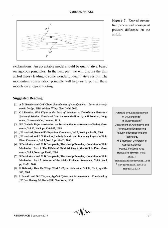
Now this handy formula can be used along with assumed stream-line patterns as shown in Figure 7 to convince ourselves that there
RESONANCE | January 2017 75

GENERAL ARTICLE
Figure 6. Curved stream-
line pattern and consequent
pressure increase at the outer
side.
( p + p )
R
Δ
∂ r
u
⎠p∂ ⎞
⎜
⎝⎛ ⎜
p
is a lift force. We start with the assumption that pressure p faraway from the airfoil is the constant free stream pressure p∞. Thepresence of the cambered airfoil has changed the pressure fieldlocally, and the disturbances caused in the velocity and pressurefields go to zero as we move far away. If we select a point B on theupper surface and roughly at mid-chord of the airfoil and reach itby moving vertically downwards from a far off point A, then thepressure should decrease to a value lower than p∞ as shown inFigure 7. It is because of the curvature of the streamlines. Con-versely, we select a point D on the lower surface and reach itby moving vertically upwards from a far off point C. Due to thecurvature of the streamlines, the pressure p at point D should behigher than p∞. Comparing pressures at points B and D, it is clearthat there is a pressure jump across the airfoil surface and conse-quent upward lift force. Associated with the pressure jump thereshould be a velocity jump with higher velocity on the upper sideas required by Bernoulli’s principle and as seen in the previoussection. This velocity jump, of course, ignores the existence ofthe boundary layers and zero velocity on the wall due to no-slipcondition on either sides.
If the vertical line ABDC in Figure 7 were in front of the airfoilor behind it, there cannot be any pressure or velocity jumps ordiscontinuities. This leads us to the inevitable conclusion thatthere must be something drastic at the leading and trailing edges.
We have described two simple models which only give qualitative
76 RESONANCE | January 2017
GENERAL ARTICLE
Figure 7. Curved stream-
line pattern and consequent
pressure difference on the
airfoil.B
A
C
D
p
p
explanations. An acceptable model should be quantitative, basedon rigorous principles. In the next part, we will discuss the thinairfoil theory leading to some wonderful quantitative results. Themomentum conservation principle will help us to put all thesemodels on a logical footing.
Suggested Reading
[1] A M Kuethe and C–Y Chow, Foundations of Aerodynamics: Bases of Aerody-
namic Design, Fifth edition, Wiley, New Delhi, 2010.
Address for Correspondence
M D Deshpande1
M Sivapragasam2
Department of Automotive and
Aeronautical Engineering
Faculty of Engineering and
Technology
M S Ramaiah University of
Applied Sciences
Peenya Industrial Area
Bengaluru 560 058, India.
Email:[email protected]
2 sivapragasam.aae.et@
msruas.ac.in
[2] O Lilienthal, Bird Flight as the Basis of Aviation: A Contribution Towards a
System of Aviation, Translated from the second edition by A W Isenthal, Long-
mans, Green and Co., London, 1911.
[3] S P Govinda Raju, Aerobasics: An Introduction to Aeronautics (Series), Reso-
nance, Vol.13, No.8, pp.836–842, 2008.
[4] J H Arakeri, Bernoulli’s Equation, Resonance, Vol.5, No.8, pp.54–71, 2000.
[5] J H Arakeri and P N Shankar, Ludwig Prandtl and Boundary Layers in Fluid
Flow, Resonance, Vol.5, No.12, pp.48–63, 2000.
[6] S Prabhakara and M D Deshpande, The No-slip Boundary Condition in Fluid
Mechanics: Part 1. The Riddle of Fluid Sticking to the Wall in Flow, Reso-
nance, Vol.9, No.4, pp.50–60, 2004.
[7] S Prabhakara and M D Deshpande, The No-slip Boundary Condition in Fluid
Mechanics: Part 2. Solution of the Sticky Problem, Resonance, Vol.9, No.5,
pp.61–71, 2004.
[8] H Babinsky, How Do Wings Work? Physics Education, Vol.38, No.6, pp.497–
503, 2003.
[9] L Prandtl and O G Tietjens, Applied Hydro- and Aeromechanics, Translated by
J P Den Hartog, McGraw-Hill, New York, 1934.
RESONANCE | January 2017 77