general caltalogue - perry · 6 wireless system, easy to install and easy to use. wireless operates...
TRANSCRIPT

GENERAL CALTALOGUE

PERRY PRODUCTS COMPLY WITH EUROPEAN DIRECTIVES
ROHS 2002/95/CE, REACH 1907/2006,
BATTERIES 2006/66/CE, RAEE 2003/96/CE

1
1969 - 2016 Over 45 years of experience in manufacturing:
The constant expansion of thermohydraulic andelectrical distribution allows to becloser and closer to its customers.Three branches: Spain, France, Germany and the presence in more than 40 countries worldwideare the heritage of the Company, which paysattention to the needs of every geographical area.
TEMPERATURE CONTROL
WIRELESS TEMPERATURE CONTROL 6
PROGRAMMABLE ROOM THERMOSTATS 16
ROOM THERMOSTATS 22
CONTROL BOXES 28
DIN RAIL MOUNTED THERMOSTATS 30
MECHANICAL CONTACT THERMOSTATS 32
MOTION AND PRESENCE DETECTORS
WALL MOUNTED 39
CEILING MOUNTED AND RECESS MOUNTED IN FALSE CEILINGS 42
LED LIGHTS WITH AND WITHOUT MOTION DETECTORS 46

2
GAS SAFETY
FOR RESIDENTIAL APPLICATIONS 80
FOR INDUSTRIAL APPLICATIONS 83
GAS SENSORS 84
SOLENOID VALVES 86
TRANSFORMERS AND CHIMES
TRANSFORMERS FOR INTERMETTENT SERVICE 90
TRANSFORMERS FOR CONTINUOUS SERVICE 91
CHIMES 92
BUZZERS 93
RELAYS
STEP RELAYS 96
DIGITAL TIME RELAY 100
INDUSTRIAL RELAYS 102
CONTROL EQUIPMENT
DIGITAL TIME SWITCHES 50
MECHANICAL TIME SWITCHES WITH TAPPETS 67
STAIRCASE TIMERS 71
PHOTOCELL LIGHTING SWITCHES FOR OUTDOOR 74DIN RAIL MOUNTING
3
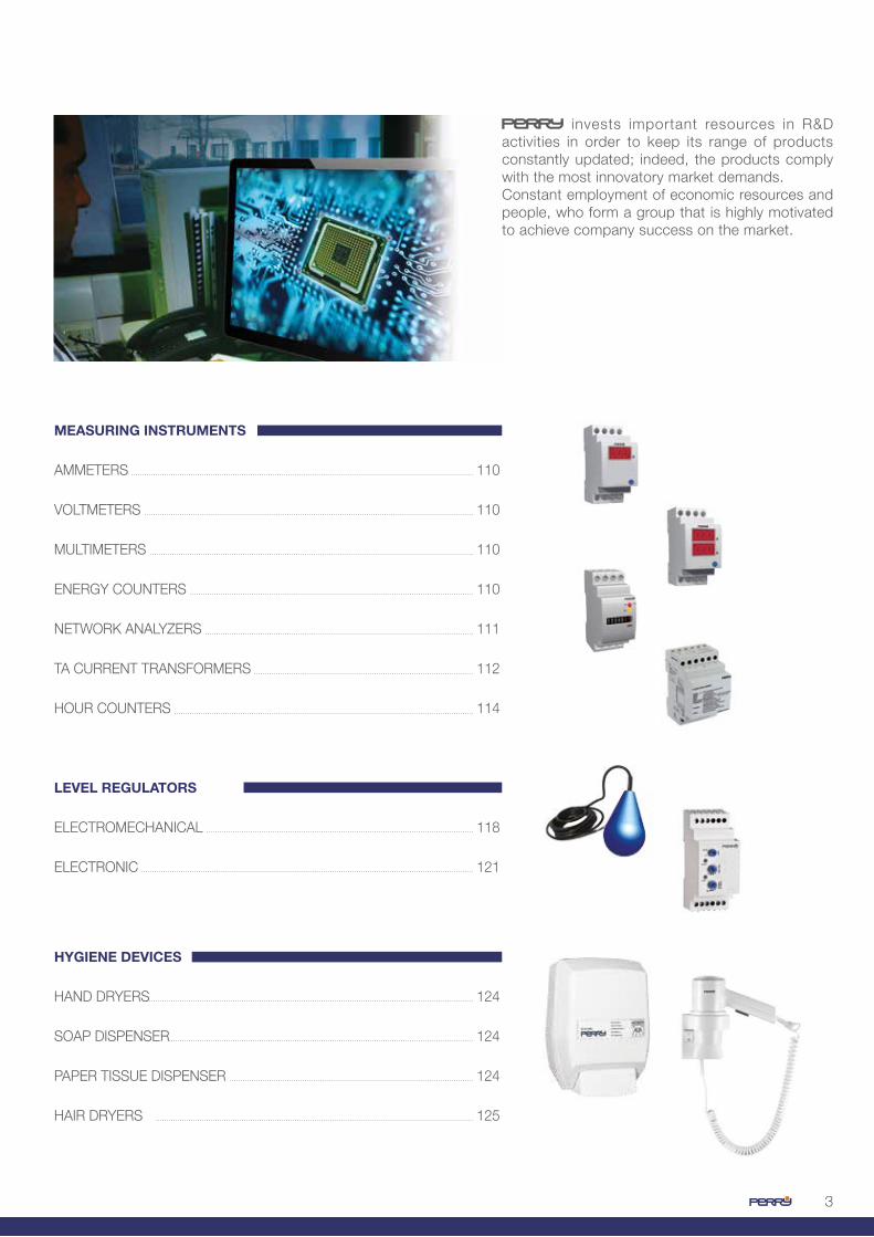
invests important resources in R&D activities in order to keep its range of products constantly updated; indeed, the products comply with the most innovatory market demands. Constant employment of economic resources and people, who form a group that is highly motivated to achieve company success on the market.
MEASURING INSTRUMENTS
AMMETERS 110
VOLTMETERS 110
MULTIMETERS 110
ENERGY COUNTERS 110
NETWORK ANALYZERS 111
TA CURRENT TRANSFORMERS 112
HOUR COUNTERS 114
LEVEL REGULATORS
ELECTROMECHANICAL 118
ELECTRONIC 121
HYGIENE DEVICES
HAND DRYERS 124
SOAP DISPENSER 124
PAPER TISSUE DISPENSER 124
HAIR DRYERS 125

44
ENERGY REQUALIFICATIONREGULATIONS
EU DIRECTIVES:DIRECTIVE 2012/27 / EUIn it are included the various measures to promote energy efficiency in the European Union, in order to ensure the achievement of the objective 20-20-20: reduction by 20% of greenhouse gas emissions and primary energy needs, meet 20% of energy consumption from renewable sources by 2020.

5
ENERGY REQUALIFICATIONREGULATIONS
To respond rapidly and effectively has developed a range of wireless products that allow temperature control in various rooms.
allows to transform a centralized system into a zone system without any intervention on the piping distribution system.
allows the temperature setting in each room on two adjustment levels over the 24 hours.
accounts consumption as actually consumed regardless of thousandths of property.
, with the rational use of heat, ensures savings of 25-30% in energy consumption.
Lower consumption and fewer harmful emissions in the atmosphere to protect the environment around us.
To save on heating costs it’s necessary to control
intelligently the temperature in the home.
temperature controllers convert centralized
systems into individual heating systems

6
Wireless system, easy to install and easy to use.
Wireless operates in 868.35 MHz radio frequency established for general use on the European territory. The construction technology ensures immunity from interference with other devices because each device is protected by a pairing code. During installation of the system each device will be programmed for univocal operation between transmitters and receivers.
• The transmission power of about 10 mW is less than the authorized power and about 100 times lower than that of mobile phones.
• The system allows to adjust the temperature in each room through the wireless control of the valves mounted on radiators in each room or in the zone manifolds.
• Ease of installation: no masonry works, without laying cables allows to transform any type of plant in a zone system obtaining substantial energy savings.
• Flexibility of use. Who is most sensitive to cold temperatures at home, will set higher temperatures, office workers can adjust their system according to their needs: temperature control according to the specific needs in each room.
• Can be used in any type of installation: with radiators, underfloor heating, electric heating, hot air heating ...
• The use of a zone heating system enables savings on heating costs of about 25-30% (statistical survey)
• The reduced use of the heating system helps you minimize the atmospheric pollution to benefit the community.
HORIZONTAL PIPING SYSTEM
VERTICAL PIPING SYSTEM
ENERGY REQUALIFICATIONWIRELESS TEMPERATURE CONTROL

7
OPERATING LOGICNormally the system foresees the installation of 2 programmable thermostats, one for the dayzone and one for the night zone.
On each of these the time profile will be programmed corresponding to the heating needs of the rooms in the day zone and in the night zone.
To obtain fine adjustment, the thermostats installed in the various rooms will be associated with the programmable thermostat.
The desired room temperature is set on the thermostat for the comfort time periods set on the zone programmable thermostat. In the time periods of reduction, the temperature in the rooms will be the one programmed on the zone programmable thermostats: the room thermostats will make sure that the temperature does not fall below such setting.The programmable thermostats and thermostats composing the system will command thecirculation of hot water in the heating elements through the opening and / or closing of thevalves on the radiators.
The system can be realized with multiple zones:4, 6, 8, etc.
The system allows to appoint one of the installed programmable thermostats as “master” of the system. In this case the setting applied on the master will determine that the whole apartment will follow the profiles and programming set on the same.
EXAMPLE:• entire home in comfort mode• entire home in reduction mode• entire home in antifreeze mode• holiday mode: heating suspension for a certain
period with automatic restart• heating suspension for house cleaning, air
exchange, etc.• telephone programming: switching On and OFF of
the heating from remote by telephone
2117
1917
°C °C
1817
1917
2217
2217
TE1 TE3
CR CR
TE2 TE4
0 7 9 12 14 18 23 24 h 0 7 9 12 14 18 23 24 h
ENERGY REQUALIFICATIONWIRELESS TEMPERATURE CONTROL
DAY ZONE
DAY ZONE
NIGHT ZONE
NIGHT ZONE
TE4Room 4 Bathroom
22 °C
TE2Room 2 Bathroom
22 °C
TE3Room 3 Bedroom
19 °C
TE1Room 1 Kitchen
18 °C
CRTX05 Living room
DAY ZONE
NIGHT ZONE
CRTX05 Lobby

8
WIRELESS TEMPERATURE CONTROL
1TX CRTX05 Wireless weekly digital programmable thermostat with 868.35 MHz RF output – white color
• Power supply 3V – 2x1.5V AA alkaline batteries – • 2” 1/3 LCD display • ON / OFF operation with adjustable differential
switch 0.2 – 0.7°C• 2 temperature levels + anti-freeze (excludable or
adjustable)• 3 preset programs (modifiable)• Minimum programming time 30 minutes• MASTER function• Aprox. lifetime 3 years
• Temperature settings protected by password• Adjustable temperature range: 5 – 39,9°C• Automatic daylight saving time change • SUMMER / WINTER option• Possibility of correction of the detected room
temperature (OFFSET).• Interruption button for cleaning operations• Range: 30 - 130m• Dimensions: (L x W x H) 120 x 21 x 80 mm
1TX TETX04 Wireless daily digital thermostat with 868.35 MHz RF output – white color
• Power supply 3V – 2x1.5V AA alkaline batteries • ON / OFF operation with adjustable differential switch
0.2 – 0.7°C• 2 temperature levels + anti-freeze (excludable or
adjustable)• approx. lifetime 3 years• SUMMER / WINTER option• Temperature settings protected by password
• Operational safety is ensured by a double transmission of information to the receiver
• Possibility of correction of the detected room temperature (OFFSET).
• Indication of ON status and LOW battery• Adjustable temperature range: 5 – 39,9°C• Range: 30 - 130m• Dimensions (L x W x H): 84 x 23 x 84 mm
1TX TETX03 Wireless daily electronic thermostat with 868.35 MHz RF output – white color
• Power supply 3V – 2x1.5V size C alkaline• ON / OFF operation with adjustable differential switch
0.3 – 0.6°C• Temperature levels 2: 1 direct 1 indirect• Range: 30 - 130m• SUM/WIN control
• ON status indicator• LOW BATTERY indicator• Radio transmission indicator• Adjustable temperature range: 5 – 30°C• Dimensions (L x W x H) 76 x 40 x 81 mm
1TX CCRX01 Status control unit zone 868.35MHz – white color
• Power supply 230V a.c. 50Hz• 1 potential-free changeover contact output:
5 (2) A / 250V
• Reception frequency: 868.35Mhz• RF signal level indicator• Dimensions (L x W x H) 133 x 25 x 90 mm
The control unit activates the load (pump boiler) with at least one open electronic valve
1TX VTRX02 Electronic actuator for water radiators with 868,35 MHz RF transceiver – white color
• Power supply 3V – 2x1.5V type C alkaline batteries • Approx. lifetime 3 years• ON / OFF operation• RF signal level indicator• IP 30• Fault and / or battery charge indicator
• Valve opening / closing condition indicator• Threaded coupling for radiators with adaptation ring
nut for the main thermostatic valves• Dimensions: (L x W x H): 62 x 70 x 97 mm
1PA BTTETX01 Table base for thermostat TETX04
Supporting base for positioning TETX04 thermostat in the most suitable place for temperature detection.
1PA BTCRTX01 Table base for wireless programmable thermostat
Supporting base for positioning CRTX05 programmable thermostat in the most suitable place for temperature detection
1PA ASVT01 Angle adapter for electronic valves on radiators
It allows the vertical installation of the electronic valves on the radiators

9
1TX RX0801/P 8-zones wall-mounted radio receiver + 1 circulation pump output – white color
• 16V power supply via BUS• Reception frequency: 868.35Mhz• BUS RS 485 output for 8-output control + 1
circulation pump control output• Manual ON / OFF control
• RF signal level indicator• Signal to control the activated circulation pump• Adjustable pump control delay 0” or 120”• Dimensions (L x W x H) 133 x 25 x 90 mm
1TX RX02/P 2-zones wall-mounted radio receiver + 1 circulation pump output – white color
• Power supply 230V a.c. 50-60Hz• Reception frequency: 868.35Mhz• 2 potential-free changeover contacts output: 5 (2) A / 250V + 1 Output to control the circulation
pump 5 (2) A / 250V a.c.
• Manual ON / OFF control,• RF signal level indicator• Signal to control the activated circulation pump• Dimensions (L x W x H) 133 x 25 x 90 mm
1TX RX01/P 1-zone wall-mounted radio receiver – white color
• Power supply 230V a.c. 50-60Hz• Reception frequency: 868.35Mhz• 1 potential-free changeover contact:output: 5 (2 )A / 250V a.c.
• Manual ON / OFF control• RF signal level indicator• Dimensions (L x W x H) 133 x 25 x 90 mm
1TX BC0401/230 4-zones Control box1TX BC0601/230 6-zones Control box1TX BC0801/230 8-zones Control box
• Power supply 230V a.c. 50-60Hz• 4 polarized outputs at 230V (1TX BC0401/230) 6 polarized outputs at 230V (1TX BC0601/230) 8 polarized outputs at 230V (1TX BC0801/230)• Load 8 (2) A / 250V a.c. + 1 output to control the
circulation pump 8 (2) A / 250V a.c.• IP 32 (IP 52 with accessory cable glands)• Connection to receiver RX0801/P with BUS RS 485
• Fault indicator LED• ON / OFF pump status indicator LED• mains presence indicator LED • ON / OFF zone status indicator LED• Dimensions (L x W x H) 250 x 76 x 43 mm
1PA PPBC01 Cable glands for control boxes
Package consists of n° 11 cable glands for control boxes, protection degree IP52
1TX TETX04RX01 Kit including 1 radio thermostat + 1 wall-mounted 1-zone radio receiver 1TX RX01/P
1TX CRTX05RX01 Kit including 1 radio programmable thermostat + 1 wall-mounted 1-zone radio receiver 1TX RX01/P
KITS FOR EXISTING SYSTEMS
CRTX05 programmable thermostat adjusts the time profiles and the temperature settings in the house. The RX01/P radio receiver activates / deactivates the connected load (pump, boiler, ...) according to the heat demand of the programmable thermostat.
TETX04 thermostat adjusts the temperature settings in the house. The RX01/P radio receiver activates / deactiva-tes the connected load (pump, boiler, ...) according to the heat demand of the thermostat.

10
WIRED TEMPERATURE CONTROL
PLANT TECHNICIn the distribution box you plan the installation of a 4-6-8 zones control box for the control of the zone valves, to which you will connect the programmable thermostats or thermostats installed in the apartment for thermoregu-lation of each room or equivalent zone.The thermoregulation products installed, programmable thermostats or thermostats, are set to ON /OFF or proportional mode depending on the heating elements used in the home.
1.2 Systems with radiant underfloor 1.2 3 thermostats are normally used (one for each thermal zone). The control box controls the thermo-electric valves in the distribution manifold and the switching off of the circulation pump. Eventually, a time switch can be connected to the control box to program the switching on and off of the system.
day zone
day zone
bathroom zone
bathroom zone
Programmable thermostat
Programmable thermostat
Thermostat Thermostat
Thermostat
Thermostat
1. Systems with individual boiler1.1 Systems with radiators 2 programmable thermostats are normally used (one for day zone, one for night zone) and a thermostat in the bathrooms. The control box controls the thermo-electric valves in the distribution manifold and the switching off of the circulation pump.
night zone
night zone

11
CONTROL BOXESAre electronic devices equipped with n ° 4 – 6 - 8 inputs connected to zone thermostats and n ° 4 – 6 - 8 outputs for control of opening / closing of the thermo-electric valves mounted on manifolds in the distribution boxes
2. CENTRALIZED SYSTEMS WITH HORIZONTAL PIPES2.1 Systems with radiators 2 programmable thermostats are normally used (one for day zone, one for night zone) and a thermostat in bathrooms. The control box controls the thermo-electric valves in the distribution manifold and switching off of the circulation pump. Eventually, a time switch can be connected to the control box to program the switching on and off of the system.
2.2 Systems with radiant underfloor 3 thermostats are normally used (one for each thermal zone). The control box controls the thermo-electric valves in the distribution manifold and the switching off of the circulation pump. Eventually, a time switch can be connected to the control box to program the switching on and off of the system.
The control boxes besides controlling thermo-electric valves connected to each output, switch off the circulation pump when all the thermo-electric valves are close.When even only one of thermo-electric valves is open, the control box reboots the circulation pump.The control boxes also have an input for connecting a time switch for programming the time profiles and an input for “winter / summer” remote switching of the system.
day zone
day zone
bathroom zone
bathroom zone
Programmable thermostat
Programmable thermostat
Thermostat Thermostat
Thermostat
Thermostat
night zone
night zone

12
WIRED TEMPERATURE CONTROL
ZEFIRO
ZEFIRO 80x80
ZEFIRO TOUCH
ZEFIRO TOUCH
NEXT
NEXT
TE530B - TE531B - TE532B
CR022A - CR022B
PROGRAMMABLE THERMOSTATS
2 DIN RAIL MOUNTING THERMOSTATS CONTACT THERMOSTATS
THERMOSTATS
DIGITAL
ELETTRONIC MECHANICALELECTRONIC FOR SWITHBOARD
DIGITAL
CR026A - CR026BCR028A - CR028BCR029A - CR029B
TE028A - TE028BTE029A - TE029B
TE526A - TE526B
TE082 - TE083 TE084
TE075 - TE076 TE077 - TE078
TE052/M TB060 - TB065 - TB071TB081 - TB088 - TB090 - TB091

13
UP&DOWN COMPACT
SLIM ZEFIRO EUROPA TEG
ZEFIRO GSM EASY
TE500A - TE500B TE501A - TE501B TE502B TE503A - TE503BTE565B - TE566B
TE065 TEG130 - TEG131TEG131RA - TEG132 TEG136
CR308/G - CR309/SCR017AG - CR017BGCR018AS - CR018BS
CR025B
CONTROL EQUIPMENT
CE MARKING STANDARDS
CONTROL BOXES
ELETTRONIC GAS EXPANSION
TE400/B - TE410/B TE402/B - TE411/B
BP04230 - BP08230
LVD: 2006/95/CE EN 60730-1, EN 60730-2-9EMC: 2004/108/CE EN 60730-1, EN 60730-2-9

14
PROGRAMMABLE THERMOSTATS
MAIN FUNCTIONAL FEATURES5 preset programs including 1 holiday programBased on historical knowledge of the market that meet the needs of most users.
1 free program with easy programming to meet the most demanding customersFreely programmable every 30‘ of the day on four different temperature levels (t1, t2, t3, td) and in a different way for each day of the week.
3 temperature levels t1, t2, t3 + antifreeze td all settable and independent
Adjustable temperatures in 0.1°C setsTo have the optimal comfort conditions and therefore improve the well-being feeling in the environment.
Summer / winter controlFor applications in heating and air conditioning systems.
Temperature offsetIf for any reason the programmable thermostat is installed in a position where the measured temperature can be influenced by external factors, you can set an offset (correction value) of the measured temperature: correction can be set from - 1.9 to + 1.9 ° C.
Intelligent / eco / optimized operationIntelligent operation: The programmable thermostat anticipates automatically the system, in order to obtain the desired temperature at the set time: the anticipation (max 2 hours) is self-adjusted according to the characteristics of the system.Eco Operation: the programmable thermostat anticipates the switching off taking advantage of the thermal inertia of the system, allowing a considerable saving of energy.Optimized operation: The programmable thermostat anticipates the switching on and off of the system.
Cleaning suspension It is used to stop for a predetermined time, the operation of the system. Without wasting energy and with ease, just press the key with the “cleaning suspension” symbol and on the screen the segments indicating 2 hours disappear: the system is turned off.
Temperature set lockingFor heating systems in holiday houses, public buildings, hotels, offices, as well as for homes, where it is necessary to determine the minimum and maximum temperatures to prevent heat theft (minimum temperature) and / or waste heat (maximum temperature).
System malfunctionIf there’s no temperature variation in the environment over a period of two hours, an alert will appear on the display. The programmable thermostat maintains its operations even in the presence of the alert.
Descaling cycleWith the “pump start” mode activated, the programmable thermostat automatically provides to start the pump or valve for two minutes every day, even in the periods of suspension, to avoidfouling and possible seizures due to inactivity. This eliminates any risk when the system is reactivated.

15
Keypad lockThe keypad can be locked to avoid any accidental change of the set program.
Factory programmingIn order to minimize the installation time, the new range of programmable thermostats is programmed in our factory. READY TO USE!
2 TYPES OF OPERATION FOR ALL KINDS OF PLANTON / OFF mode with temperature differential The differential must be set according to the system’s thermal inertia; a low setting is recommended for systems with radiators (e.g. made of cast iron) and a high setting for systems with fan-coils.
Setting exampleT = 20°C - cycle = 10’t = 20,5°C consumption always OFFt = 20,4°C consumption 1’ ON - 9’ ‘ OFFt = 20,3°C consumption 2’ ON - 8’ OFFt = 20,2°C consumption 3’ ON - 7’ OFFt = 20,1°C consumption 4’ ON - 6’ OFF
t = 20,0°C consumption 5’ ON - 5’ OFFt = 19,9°C consumption 6’ ON - 4’ OFFt = 19,8°C consumption 7’ ON - 3’ OFFt = 19,7°C consumption 8’ ON - 2’ OFFt = 19,6°C consumption 9’ ON - 1’ OFFt = 19,5°C consumption always ON
°C20,820,620,4
20,220,0
19,819,619,419,2
0 2 4 6 8 10 Minuti
Utenza OFF
Utenza ON
Proportional modeIn order to adjust the temperature with set cycles of 7, 10, 15, 20 min., this system allows to maintain the desired temperature more stable, increasing the comfort feeling to the user and saving on energy consumption.A long cycle is recommended for systems with high thermal inertia (cast-iron radiators, floor systems) and a short cycle for systems with low thermal inertia (fan-coils).
OVERHEATING
HYSTERESIS
OVERHEATING
Holiday programFor those who are away from home for several days, the modes “Countdown” or “Weekend” are provided, which suspend the operation of the programmable thermostat for a predetermined period of time, maintaining the temperature at antifreeze level.
Large LCD backlit display for perfect visibilityThe backlight turns on when you press any key and turns off after 6 seconds (Art. CR026, CR028, CR029, TE028, TE029, TE526).
Automatic daylight saving time changeThe new range of programmable thermostats equipped with internal calendar allows the automatic daylight saving time change.
PROPORTIONAL

16
CONTROL TEMPERATURE WITH STYLE
WALL MOUNTED PROGRAMMABLE THERMOSTATS
NEXT
WIRED TEMPERATURE CONTROL

1717
1CR CR028A“NEXT” series menu driven weekly digital programmable thermostat, 3V, anthracite color
1CR CR028B“NEXT” series menu driven weekly digital programmable thermostat, 3V, white color
1CR CR029A“NEXT” series menu driven weekly digital programmable thermostat, 230V, anthracite color
1CR CR029B“NEXT” series menu driven weekly digital programmable thermostat, 230V, white color
Backlit display
Backlit display
• Multilanguage menu• Power supply: 3V AA alkaline batteries• 4.3” backlit LCD display• Output: 1 potential free changeover contact:
5 (3) A / 250V a.c.• ON / OFF operation mode with adjustable differential
from 0.2 - 1.2 ° C or modulating with control period from 7 - 20 min
• 4 preset modifiable programs (2 Winter + 2 summer)• Temperature levels: 3 + anti-freeze• Independent manual temperature• Temperature adjustable by 0,1°C sets• Minimum programming: 30 minutes• Temporary / permanent manual operation• Automatic daylight saving time change• Pausing for household cleaning
• Input for telephone programmer or remote contact• Summer / Winter control• Input for remote probe (only for battery operated
devices)• Holidays program• Pump activation program• Temperature setting lock• User password• Installer password• Backlighting: timed • Relay status indicator• Temperature offset: adjustable according to product
positioning• Temperature setting range: 5 - 37.7°C• Dimensions: (L x W x H) 128.5 x 88.5 x 26 mm
• Multilanguage menu• Power supply: 230V 50-60Hz• 4.3” backlit LCD display• Output: 1 potential free changeover contact:
5 (3) A / 250V a.c.• ON / OFF operation mode with adjustable differential
from 0.2 - 1.2 ° C or modulating with control period from 7 - 20 min
• 4 preset modifiable programs (2 Winter + 2 summer)• Temperature levels: 3 + anti-freeze• Independent manual temperature• Temperature adjustable by 0,1°C sets• Minimum programming: 30 minutes• Temporary / permanent manual operation• Automatic daylight saving time change• Pausing for household cleaning
• Input for telephone programmer or remote contact• Summer / Winter control• Holidays program• Pump activation program• Temperature setting lock• User password• Installer password• Backlighting: timed and fixed• Relay status indicator• Temperature offset: adjustable according to product
positioning• Temperature setting range: 5 - 37.7°C• Dimensions: (L x W x H) 128.5 x 88.5 x 26 mm
1PA STE02 NTC temperature probe with 4 m cable, for CRO28
Detection probe with 2x1.5 mm2 shielded cable - IP68 - Extendable up to max. 20 m.The probe allows temperature sensing in another room, underfloor or outside.
Below 18,0 °C the keys light up in green,indicating low consumption
Between 18,1 °C and 21 °C the keys lightup in blue, indicating optimal consumption
Above 21,1 °C the keys light up in redindicating consumtion over needs
Keys lit in different colors depending on set temperature

1818
WIRED TEMPERATURE CONTROLWALL MOUNTED PROGRAMMABLE THERMOSTATS
• TOUCH SCREEN backlit Lcd display• Power supply 3V – 2x1.5V AA alkaline• 1 potential-free changeover contact output:
5 (3) A / 250V a. c.• ON / OFF operation mode with adjustable differential
switch from 0,2 - 1,2°C or proportional with 7 - 20 minutes adjustable control period
• 3 temperature levels + anti-freeze• 4 preset modifiable programs • Temperature offset: adjustable according to product
positioning• Temperature adjustable by 0,1°C sets• Consumption counter• Minimum programming 30 minutes• Temporary / permanent manual operation• Input for remote temperature probe
• Telephone control input• Temperature + key lock• Automatic daylight saving time change• Pausing for household cleaning• User password• Installer password• Timed backlit display• Relay status indicator • Summer / Winter control• Wall or semi-recess mounting• Temperature setting range: 5 - 37.7°C• Dimensions (L x W x H) 120 x 27,6 x 82 mm
1CR CR026A “ZEFIRO TOUCH SCREEN” series menu driven weekly digital programmable thermostat, 3V, anthracite color
1CR CR026B “ZEFIRO TOUCH SCREEN” series menu driven weekly digital programmable thermostat, 3V, white color
1PA STE02 Temperature probe with 4 m cable, for CRO26
Detection probe with 2x1.5 mm2 shielded cable - IP68 - Extendable up to max. 20 m.The probe allows temperature sensing in another room, underfloor or outside.
Backlit displayTouch Screen
Time and standard time profile are preset at the factory and can be modified by the user at any time
Touch Screen

1919
1CR CR025B“ZEFIRO” series weekly digital programmable thermostat 230V with GSM modem, white color
• Power supply 230V 50-60Hz• Consumption counter• Built-in GSM modem for receiving remote controls• Telephone control input• 3” backlit LCD display• 1 potential-free changeover contactoutput:
8 (2) A / 250Va.c.• ON / OFF operation with adjustable differential switch
0.2 – 2°C or proportional with control period 7/10/13/20 minutes• 4 preset programs + 1 free• Temperature levels 3 + anti-freeze• Temperature adjustable by 0.1°C sets• Minimum programming 30 minutes• Autonomy 24 months (rechargeable battery on GSM
base, 36 hours)
• Temporary / permanent manual operation• Timed or fixed backlighting• System irregularity signalling• Pausing for household cleaning• Intelligent operation• SUM/WIN control• Holiday Program• Pump activation program• Temperature setting lock• Temperature offset: adjustable according to product •
positioning (winter / summer)• Temperature setting range: 5 - 37.7°C• Dimensions (L x W x H) 120 x 42 x 82 mm
Backlit display
You can access to the programmable thermostat from every place thanks to the integral GSM modem

2020
WIRED TEMPERATURE CONTROLWALL MOUNTED PROGRAMMABLE THERMOSTATS
1CR CR017AG “UP & DOWN Compact” daily digital programmable thermostat 3V series - anthracite colour
1CR CR017BG “UP & DOWN Compact” daily digital programmable thermostat 3V series - white colour
• Power supply 3V – 2x1.5V AAA alkaline• 4” ½ LCD display• 1 potential-free changeover contact output:
5 (2) A / 250V a. c.• 10 Temperature levels + anti-freeze• Consumption counter• Minimum programming time 60 minutes• Temperature offset: adjustable according to product
positioning (winter / summer)• Automatic daylight saving time adjustment• Preset at the factory• ON / OFF operation mode with adjustable differential
switch or proportional with control period 7 / 10 / 13 / 20 minutes
• 3 operation modes: intelligent / eco / optimised• Temporary / permanent manual operation modes• Autonomy: 12 months• Holiday Program• Pausing for household cleaning• Pump activation program• Temperature setting lock• Keypad lock• Password protection for access to keyboard• Heating setting range: 15 - 17 - 18 - 19 - 20 - 20,5 -
21 22 - 23 - 24°C• Cooling setting range: 20 - 22 - 23 - 24 - 25 - 26 - 27
- 28 - 32 - 36 °C• Dimensions (L x W x H) 133 x 26 x 90 mm
Time and standard heating program are preset at the factory and can be modified by the user at any time
1CR CR018AS “UP & DOWN Compact” weekly digital programmable thermostat 3V series - anthracite colour
1CR CR018BS“UP & DOWN Compact” weekly digital programmable thermostat 3V series - white colour
• Power supply 3V – 2x1.5V AAA alkaline• 4” ½ LCD display• 1 potential-free changeover contact output:
5 (2) A / 250V a. c.• 10 Temperature levels + anti-freeze• Consumption counter• Minimum programming time 60 minutes• Temperature offset: adjustable according to product
positioning (winter / summer)• Automatic daylight saving time adjustment• Preset at the factory• ON / OFF operation mode with adjustable differential
switch or proportional with control period 7 / 10 / 13 / 20 minutes
• 3 operation modes: intelligent / eco / optimised• Temporary / permanent manual operation modes• Autonomy: 12 months• Holiday Program• Pausing for household cleaning• Pump activation program• Temperature setting lock• Keypad lock• Password protection for access to keyboard• Heating setting range: 15 - 17 - 18 - 19 - 20 - 20,5 -
21 22 - 23 - 24°C• Cooling setting range: 20 - 22 - 23 - 24 - 25 - 26 - 27
- 28 - 32 - 36 °C• Dimensions (L x W x H) 133 x 26 x 90 mm
Time and standard heating program are preset at the factory and can be modified by the user at any time

21
1CR CR308/G “EASY” series Daily digital analogue programmable thermostat 3V – white color
1CR CR309/S “EASY” series Weekly digital analogue programmable thermostat 3V – white color
• Power supply 3V – 2x1.5V AA alkaline• 2” 2/3 LCD display • 1 potential-free changeover contact output:
8 (2) A / 250Va.c.• ON / OFF operation with adjustable differential switch
0.3 / 0.5 / 0.7 / 0.9°C or adjustable proportional cycle 7 / 10 / 15 / 20 min
• Temperature adjustment on display• Temperature levels 2 + anti-freeze fixed at 5°C• Autonomy: 24 months
• Minimum programming 30 minutes• Permanent manual operation• Total ON / OFF function• Temperature mechanical lock• Telephone control input• Temperature setting range: 5 - 37.7°C• Dimensions (L x W x H) 121.5 x 31.5 x 82 mm
21

22
WIRED TEMPERATURE CONTROLWALL MOUNTED THERMOSTATS
MAIN FUNCTIONAL FEATURES
Adjustable temperatures in 0.1°C setsTo have the optimal comfort conditions and therefore improve the well-being feeling in the environment.
Summer / winter controlFor applications in heating and air conditioning systems.
Temperature offsetIf for any reason the programmable thermostat is installed in a position where the measured temperature can be influenced by external factors, you can set an offset (correction value) of the measured temperature: correction can be set from - 1.9 to + 1.9 ° C.
Temperature set lockingFor heating systems in holiday houses, public buildings, hotels, offices, as well as for homes, where it is necessary to determine the minimum and maximum temperatures to prevent heat theft (minimum temperature) and / or waste heat (maximum temperature).
2 temperature levels comfort and night reduction control + antifreeze t dAll settable and indipendent
2 TYPES OF OPERATION FOR ALL KINDS OF PLANTON / OFF mode with temperature differential The differential must be set according to the system’s thermal inertia; a low setting is recommended for systems with radiators (e.g. made of cast iron) and a high setting for systems with fan-coils.
Setting exampleT = 20°C - cycle = 10’t = 20,5°C consumption always OFFt = 20,4°C consumption 1’ ON - 9’ ‘ OFFt = 20,3°C consumption 2’ ON - 8’ OFFt = 20,2°C consumption 3’ ON - 7’ OFFt = 20,1°C consumption 4’ ON - 6’ OFF
t = 20,0°C consumption 5’ ON - 5’ OFFt = 19,9°C consumption 6’ ON - 4’ OFFt = 19,8°C consumption 7’ ON - 3’ OFFt = 19,7°C consumption 8’ ON - 2’ OFFt = 19,6°C consumption 9’ ON - 1’ OFFt = 19,5°C consumption always ON
°C20,820,620,4
20,220,0
19,819,619,419,2
0 2 4 6 8 10 Minuti
Utenza OFF
Utenza ON
Proportional modeIn order to adjust the temperature with set cycles of 7, 10, 15, 20 min., this system allows to maintain the desired temperature more stable, increasing the comfort feeling to the user and saving on energy consumption.A long cycle is recommended for systems with high thermal inertia (cast-iron radiators, floor systems) and a short cycle for systems with low thermal inertia (fan-coils).
OVERHEATING
HYSTERESIS
OVERHEATING
PROPORTIONAL

2323
1TP TE028A“NEXT” series menu driven daily digital thermostat, 3V, anthracite color
1TP TE028B“NEXT” series menu driven daily digital thermostat, 3V, white color
1TP TE029A“NEXT” series menu driven daily digital thermostat, 230V, anthracite color
1TP TE029B“NEXT” series menu driven daily digital thermostat, 230V, white color
• Power supply: 3V AA alkaline batteries• Multilanguage menu• 4.3” backlit LCD display• Backlit buttons• Output: 1 potential free changeover contact:
5 (3) A / 250Va.c.• ON / OFF operation mode with adjustable differential
from 0.2 - 1.2 ° C or modulating with control period from 7 - 20 min
• Temperature levels: 2 + anti-freeze• Temperature adjustable by 0,1°C sets• Pausing for household cleaning• Input for telephone programmer or remote contact
• Input for remote probe• Summer / Winter control• Pump activation program• Temperature setting lock• User password• Installer password• Backlighting: timed • Relay status indicator• Temperature offset: adjustable according to product
positioning• Wall mounting• Temperature setting range: 5 - 37.7°C• Dimensions: (L x W x H) 128.5 x 88.5 x 26 mm
• Power supply: 230Vac 50-60Hz• Multilanguage menu• 4.3” backlit LCD display• Backlit buttons• Output: 1 potential free changeover contact: 5 (3) A / 250Va.c.• ON / OFF operation mode with adjustable differential
from 0.2 - 1.2 ° C or modulating with control period from 7 - 20 min
• Temperature levels: 2 + anti-freeze• Temperature adjustable by 0,1°C sets• Pausing for household cleaning• Input for telephone programmer or remote contact
• Summer / Winter control• Pump activation program• Temperature setting lock• User password• Installer password• Backlighting: timed and fixed• Temperature offset: adjustable according to product positioning• Wall mounting• Temperature setting range: 5 - 37.7°C• Dimensions: (L x W x H) 128.5 x 88.5 x 26 mm
Backlit display
Backlit display
Below 18,0 °C the keys light up in green,indicating low consumption
Between 18,1 °C and 21 °C the keys lightup in blue, indicating optimal consumption
Above 21,1 °C the keys light up in redindicating consumtion over needs
Keys lit in different colors depending on set temperature
1PA STE02 NTC temperature probe with 4 m cable, for TE028
Detection probe with 2x1.5 mm2 shielded cable - IP 68 - Extendable up to max. 20 m.The probe allows temperature sensing in another room, underfloor or outside.

2424
1TP TE526A“ZEFIRO” TOUCH SCREEN series daily digital thermostat, 3V, anthracite color
1TP TE526B“ZEFIRO” TOUCH SCREEN series daily digital thermostat, 3V, white color
• Power supply 3V – 2 x 1.5V AA alkaline batteries• TOUCH SCREEN backlit LCD display• 1 potential-free changeover contact output:
5 (3) A / 250V a. c.• ON / OFF operation mode with adjustable differential
switch from 0,2 - 1,2°C or proportional with 7 - 20 minutes adjustable control period
• 2 temperature levels + anti-freeze• Temperature adjustable by 0,1°C sets
• Temperature offset: adjustable according to product positioning (winter / summer)• Telephone control input• Timed backlit display• Relay status indicator • Summer / Winter control• Wall or semi-recess mounting• Temperature setting range: 5 - 37.7°C• Dimensions (L x W x H) 120 x 27,6 x 82 mm
Backlit display
1TP TE530B“ZEFIRO” series 80 x 80 digital thermostat 3V, white color
• Power supply 3V – 2x1.5V AAA alkaline batteries• 2” 1/3 LCD display• 1 potential-free changeover contact output:
5 (3) A / 250Va.c.• ON / OFF operation with adjustable differential switch
0.2 – 2°C or proportional with 7/10/13/20 minutes control period
• Temperature levels 2 + anti-freeze• Temperature adjustable by 0.1°C sets
• LOW BAT indicator• Autonomy: 24 months• Relay status indicator• SUM/WIN control• Temperature setting lock• Temperature offset: adjustable according to product positioning • Temperature setting range: 5 - 37.7°C• Dimensions (L x W x H) 84 x 23 x 84 mm
1TP TE532B“ZEFIRO” series 80x80 digital thermostat 230V, for public areas white color
1TP TE531B“ZEFIRO” series 80 x 80 digital thermostat 230V, white color
• Power supply 230V a.c. 50-60Hz• 2” 1/3 LCD display• 1 potential-free changeover contact output:
5 (3) A / 250Va.c.• ON / OFF operation with adjustable differential switch
0.2 – 2°C or proportional with 7/10/13/20 minutes control period
• Temperature levels 2 + anti-freeze• Temperature adjustable by 0.1°C sets
• LOW BAT indicator• Relay status indicator• SUM/WIN control• Temperature setting lock• Temperature offset: adjustable according to product positioning• Temperature setting range: 5 - 37.7°C• Dimensions (L x W x H) 84 x 23 x 84 mm
• Power supply 230V a.c. 50-60Hz• 2” 1/3 LCD display• 1 potential-free changeover contact output:
5 (3) A / 250Va.c.• ON / OFF operation with adjustable differential switch
0.2 – 2°C or proportional with 7/10/13/20 minutes control period
• Temperature levels 2 + anti-freeze• Temperature adjustable by 0.1°C sets• Temperature setting range: 5 - 37.7°C
• Dimensions (L x W x H) 89,7 x 27 x 87,4 mm
Inaccessible controls, reserved to installer:- temperature SET adjustment- SUM / WIN control- on /off- adjustment settings- Temperature offset: adjustable according to product positioning
WIRED TEMPERATURE CONTROLWALL MOUNTED THERMOSTATS
TE532specifically for use in public areas

25
1TP TE400/B“SLIM” series digital thermostat 3V with ON / OFF / NIGHT REDUCTION control, white color
• Power supply 3V – 2x1.5V AAA alkaline batteries• 1” LCD display• 1 potential-free changeover contact output:
8 (2) A / 250V a.c.• ON / OFF operation with settable differential switch 0.3
/ 0.5 / 0.7 / 0.9°C• Adjustment according to a graduated scale with
analogue and digital setting• 1 temperature level with continuous adjustment + fixed
reduced control -4°C on the set value
• Autonomy: 12 months• ON / OFF / NIGHT REDUCTION control• LOW BAT indicator LED• Relay status indicator LED• Remote night reduction control input• Temperature setting lock• Temperature setting range: 5 - 30°C• Dimensions (L x W x H) 120 x 21 x 80 mm
1TP TE402/B“SLIM” series digital thermostat 3V with SUMMER / OFF / WINTER control, white color
• Power supply 3V – 2x1.5V AAA alkaline batteries• 1” LCD display• 1 potential-free changeover contact output:
8 (2) A / 250V a.c.• ON / OFF operation with settable differential switch
0.3 / 0.5 / 0.7 / 0.9°C• Adjustment according to a graduated scale with
analogue and digital setting• 1 temperature level with continuous adjustment + fixed
reduced control -4°C on the set value
• Autonomy: 12 months• SUMMER / OFF / WINTER control• LOW BAT indicator LED• Relay status indicator LED• Remote night reduction control input• Temperature setting lock• Temperature setting range: 5 - 30°C• Dimensions (L x W x H) 120 x 21 x 80 mm
1TP TE410/B“SLIM” series digital thermostat 230V with ON / OFF NIGHT REDUCTION control, white color
• Power supply 230V a.c. 50-60Hz• 1” LCD display• 1 potential-free changeover contact output:
8 (2) A / 250V a.c.• ON / OFF operation with settable differential switch
0.3 / 0.5 / 0.7 / 0.9°C• Adjustment according to a graduated scale with
analogue and digital setting• 1 temperature level with continuous adjustment + fixed
reduced control -4°C on the set value
• ON / OFF / NIGHT REDUCTION control• LOW BAT indicator LED• Relay status indicator LED• Remote night reduction control input• Temperature setting lock• Temperature setting range: 5 - 30°C• Dimensions (L x W x H) 120 x 21 x 80 mm
1TP TE411/B“SLIM” series digital thermostat 230V with SUMMER / OFF / WINTER control, white color
• Power supply 230V a.c. 50-60Hz• 1” LCD display• 1 potential-free changeover contact output:
8 (2) A / 250V a.c.• ON / OFF operation with settable differential switch
0.3 / 0.5 / 0.7 / 0.9°C• Adjustment according to a graduated scale with
analogue and digital setting• 1 temperature level with continuous adjustment + fixed
reduced control -4°C on the set value
• SUMMER / OFF / WINTER control• LOW BAT indicator LED• Relay status indicator LED• Remote night reduction control input• Temperature setting lock• Temperature setting range: 5 - 30°C• Dimensions (L x W x H) 120 x 21 x 80 mm

26
WIRED TEMPERATURE CONTROLWALL MOUNTED THERMOSTATS
1TP TE502B“ZEFIRO” series electronic thermostat with floor probe, white color
• Power supply 230V a.c. 50-60Hz• 1 potential-free changeover contact output:
8 (2) A / 250V a.c.• ON / OFF operation with fixed differential at 0.4°C• ON / OFF control• Temperature adjustment on graduated scale with
mechanical index set-point• 1 temperature level with continuous adjustment
• Wall mounting• Remote input for night reduction -4°C on the set-point
value• Set-point with mechanical temperature lock• Relay status indicator LED• Mains connection indicator LED• Temperature setting range: 0 - +60°C• Dimensions (L x W x H) 120 x 27.5 x 81 mm
1TP TE501A“ZEFIRO” series electronic thermostat with ON / OFF control, anthracite color
1TP TE501B“ZEFIRO” series electronic thermostat with ON / OFF control, white color
• Power supply 230V a.c. 50-60Hz• 1 potential-free changeover contact output:
8 (2) A / 250V a.c.• ON / OFF operation with fixed differential at 0.4°C• ON / OFF control• Temperature adjustment on graduated scale with
mechanical index set-point• 1 temperature level with continuous adjustment
• Wall mounting or semi recess• Remote input for night reduction -4°C on the set-point
value• Set-point with mechanical temperature lock• Relay status indicator LED• Mains connection indicator LED• Temperature setting range: 5 - 30°C• Dimensions (L x W x H) 120 x 27.5 x 81 mm
1TP TE500A“ZEFIRO” series electronic thermostat with LED, anthracite color
1TP TE500B“ZEFIRO” series electronic thermostat with LED, white color
• Power supply 230V a.c. 50-60Hz• 1 potential-free changeover contact output:
8 (2) A / 250V a.c.• ON / OFF operation with fixed differential at 0.4°C• Temperature adjustment on graduated scale with
mechanical index set-point• 1 temperature level with continuous adjustment• Wall mounting or semi recess
• Remote input for night reduction -4°C on the set-point value
• Set-point with mechanical temperature lock• Relay status indicator LED• Mains connection indicator LED• Temperature setting range: 5 - 30°C• Dimensions (L x W x H) 120 x 27.5 x 81 mm
1TP TE503A“ZEFIRO” series electronic thermostat with SUMMER / WINTER control, anthracite color
1TP TE503B“ZEFIRO” series electronic thermostat with SUMMER / WINTER control, white color
• Power supply 230V a.c. 50-60Hz• 1 potential-free changeover contact output:
8 (2) A / 250V a.c.• ON / OFF operation with fixed differential at 0.4°C• SUMMER / OFF / WINTER control• Temperature adjustment on graduated scale with
mechanical index set-point• 1 temperature level with continuous adjustment• Wall mounting or semi recess
• Remote input for night reduction -4°C on the set-point value
• Set-point with mechanical temperature lock• Relay status indicator LED• WINTER / SUMMER indicator LED• Mains connection indicator LED• Temperature setting range: 5 - 30°C• Dimensions (L x W x H) 120 x 27.5 x 81 mm

27
1TP TE566BElectronic thermostat “EUROPA” series for “Fan Coil” with SUMMER / OFF / WINTER control, white color
• Power supply 230V a.c. 50-60Hz• 1 polarized NO contact output: 5 (2 )A / 250V a.c.• Proportional operation with fixed control period• SUMMER / OFF / WINTER control• I° II° III° Speed control • Temperature adjustment on graduated scale with
mechanical index set-point
• 1 Temperature level with continuous adjustment• Set-point with mechanical temperature lock• Relay status indicator LED• Temperature setting range: 5 - 30°C• Dimensions (L x W x H) 74 x 36 x 74 mm
1TP TE565B“ZEFIRO” series electronic thermostat for Fan Coil with SUMMER / OFF / WINTER control, white color
• Power supply 230V a.c. 50-60Hz• 1 polarized NO contact output: 5 (2) A / 250V a.c.• Proportional operation with fixed control period• SUMMER / OFF / WINTER control• I° II° III° Speed control • Temperature adjustment on graduated scale with
mechanical index set-point• 1 temperature level with continuous adjustment
• Set-point with mechanical temperature lock• Relay status indicator LED• SUMMER / WINTER indicator LED• Power supply indicator LED• Temperature setting range: 5 - 30°C• Dimensions (L x W x H) 120 x 27.5 x 81 mm
1TP TE065“ZEFIRO” series electronic thermostat for “Fan Coil” with SUMMER / OFF / WINTER control, white color
• Power supply 230V a.c. 50-60Hz• 1 polarized NO contact output: 5 (2 ) A / 250V a.c.• Proportional operation with fixed control period• SUMMER / OFF / WINTER control• I° II° III° Speed control • Temperature adjustment on graduated scale with
mechanical index set-point
• 1 Temperature level with continuous adjustment• Set-point with mechanical temperature lock• Relay status indicator LED• Temperature setting range: 5 - 30°C• Dimensions (L x W x H) 74 x 36 x 74 mm

28
1TG TEG130“TEG” series gas expansion thermostat without LED indicator, white color
• Power supply 230V a.c. 50-60Hz• 1 potential-free changeover contact output:
10 (2) A / 250V a.c.• ON / OFF operation with fixed differential switch• 1 temperature level with continuous adjustment
• Temperature adjustment on graduated scale with mechanical index set-point
• Set-point with mechanical temperature lock• Temperature setting range: 5 - 30°C• Dimensions (L x W x H) 74 x 40 x 74 mm
1TG TEG132“TEG” series gas expansion thermostat with LED indicator and ON / OFF control, white color
• Power supply 230V a.c. 50-60Hz• 1 potential-free changeover contact output:
10 (2) A / 250V a.c.• ON / OFF operation with fixed differential switch• ON / OFF control• 1 temperature level with continuous adjustment
• Temperature adjustment on graduated scale with mechanical index set-point
• Set-point with mechanical temperature lock• ON / OFF indicator LED of the connected load• Temperature setting range: 5 - 30°C• Dimensions (L x W x H) 74 x 40 x 74 mm
1TG TEG131“TEG” series gas expansion thermostat with LED indicator, white color
• Power supply 230V a.c. 50-60Hz• 1 potential-free changeover contact output:
10 (2) A / 250V a.c.• ON / OFF operation with fixed differential switch• Temperature adjustment on graduated scale with
mechanical index set-point
• 1 temperature level with continuous adjustment• Set-point with mechanical temperature lock• ON / OFF indicator LED of the connected load• Temperature setting range: 5 - 30°C• Dimensions (L x W x H) 74 x 40 x 74 mm
1PA TEG03B “TEG”series base for thermostat installation
1TG TEG136Gas expansion thermostat “TEG” series with LED indicator and SUMMER / WINTER control, white color
• Power supply 230V a.c. 50-60Hz• 1 potential-free changeover contact output:
10 (2) A / 250V a.c.• ON / OFF operation with fixed differential switch• SUMMER / WINTER control• 1 temperature level with continuous adjustment
• Temperature adjustment on graduated scale with mechanical index set-point
• Set-point with mechanical temperature lock• ON / OFF indicator LED of the connected load• Temperature setting range: 5 - 30°C• Dimensions (L x W x H) 74 x 40 x 74 mm
1TG TEG131RA“TEG” series gas expansion thermostat with LED indicator and Accelerating resistance, white color
• Power supply 230V a.c. 50-60Hz• 1 potential-free changeover contact output:
10 (2) A / 250V a.c.• ON / OFF operation with fixed differential switch• Temperature adjustment on graduated scale with
mechanical index set-point
• 1 temperature level with continuous adjustment• Set-point with mechanical temperature lock• Accelerating resistance• ON / OFF indicator LED of the connected load• Temperature setting range: 5 - 30°C• Dimensions (L x W x H) 74 x 40 x 74 mm
Base for TEG” thermostat installation “in round and / or rectangular recessed boxes
WIRED TEMPERATURE CONTROLWALL MOUNTED THERMOSTATS

29
WIRED TEMPERATURE CONTROLCONTROL BOXES
1AC BP042304-zones control box with 4 +1 relay outputs
• Power supply 230V a.c. – 50Hz• Potential-free changeover contacts: 10 A / 250V a.c.• 4 controllable zones• Output for active pump control with at least one open
zone valve• Output controlled by a time switch• Remotely controlled SUM / WIN output
• WINTER operation indicator LED• SUMM ER operation indicator LED• ON / OFF pump• control indicator LED• Protection degree IP 30• Dimensions (L x W x H) 250 x 76 x 43 mm
1AC BP082304-zones control box with 8 +1 relay outputs
• Power supply 230V a.c. – 50Hz• Potential-free changeover contacts: 10 A / 250V a.c.• 8 controllable zones• Output for active pump control with at least one open
zone valve• Output controlled by a time switch• Remotely controlled SUM / WIN output
• WINTER operation indicator LED• SUMM ER operation indicator LED• ON / OFF pump• control indicator LED• Protection degree IP 30• Dimensions (L x W x H) 250 x 76 x 43 mm
FUNCTIONAL FEATURESThe control boxes are electronic devices equipped with 4-8 inputs and 4-8 outputs for control of opening / closing of the electro valves mounted on distribution manifolds. Intelligent operation mode to start or stop any circulation pump installed in the hydraulic distribution box and / or the circulation pump of the individual boiler and / or the zone valve. When all the electro valves are close, the control box stops the pump / zone valve. When even only one of electro valves is open, the control box restarts the pump or the zone valve.Input for the connection of a time switch for programming the operating times of the heating system of the apartment (and of offices) and input for remote control switching of the system for winter / summer mode.
Inputs from zone programmable thermostasts and thermostats
Output for electro valve control
Input time switches for time profiles
Input summer / winter remote control
Output for circulation pump control
GREEN LED ON = ON (mains voltage ON)HEATING mode operationHEATING mode operation
Label with zone assignment
GREEN LED ON = ON (mains voltage ON)COOLING mode operation
Status of the Pump command outputLED ON = output activated
ON / OFF LED status of thermal zones

30
WIRED TEMPERATURE CONTROLDIN RAIL MOUNTED THERMOSTATS
1TM TE082 Electronic thermostat with adjustment on 2 temperature levels Comfort and Reduction - 2 DIN
• Power supply 230V a.c. – 50Hz• 1 potential-free changeover contact output:
16 (3) A / 250V a.c.• ON / OFF operation with adjustable differential switch
0.5-2.5°C• ON / OFF / ANTI-FREEZE control• Comfort / reduction / automatic remote selection control• 2 graduated scales with adjustment index• 2 temperature levels with continuous adjustment• Adjustable night reduction remote input
• Set-point with mechanical temperature lock• Relay status indicator LED• Comfort indicator LED• Night reduction indicator LED• Equipped with NTC-type remote probe, with white and
anthracite caps to be recessed in wiring devices blind plug, extendedable up to max. 100 m with shielded cable
• Temperature setting range: 5 - 30°C• Dimensions (L x W x H) 35 x 60 x 128 mm
1TM TE083Electronic thermostat with ON / OFF / ANTI-FREEZE - 2 DIN
• Power supply 230V a.c. – 50Hz• 1 potential-free changeover contact output:
16 (3) A / 250V a.c.• ON / OFF operation with adjustable differential switch
0.5-2.5°C• ON / OFF / ANTI-FREEZE control• Graduated scale with adjustment index• 1 temperature level with continuous adjustment• Adjustable night reduction remote input
• Relay status indicator LED• Night reduction indicator LED• Equipped with NTC-type remote probe, with white and
anthracite caps to be recessed in wiring devices blind plug, extendedable up to max. 100 m with shielded cable
• Temperature setting range: 5 - 30°C• Dimensions (L x W x H) 35 x 60 x 128 mm
1TM TE084Electronic thermostat with SUMMER / OFF / WINTER - 2 DIN
• Power supply 230V a.c. – 50Hz• 1 potential-free changeover contact output:
16 (3) A / 250V a.c.• ON / OFF operation with adjustable differential switch
0.5-2.5°C• SUMMER / OFF / WINTER control• Graduated scale with adjustment index• 1 temperature level with continuous adjustment• Adjustable night reduction remote input
• Relay status indicator LED• Night reduction indicator LED• Equipped with NTC-type remote probe, with white and
anthracite caps to be recessed in wiring devices blind plug, extendedable up to max. 100 m with shielded cable
• Temperature setting range: 5 - 30°C• Dimensions (L x W x H) 35 x 60 x 128 mm
1TM TE052/MElectronic thermostat for switchboards - 2 DIN
For switchboards cooling and anti-condensation• Power supply 230V a.c. – 50Hz• 1 potential-free changeover contact output:
16 (3 )A / 250V a.c.• ON / OFF operation with fixed differential switch 2°C• 2 graduated scales with adjustment index• Cooling adjustment range +20°C / +60°C• Anticondensation adjustment range +0°C / +10°C• 2 temperature levels with continuous adjustment
• Remote probe input• Relay status indicator LED• Damaged probe indicator LED• Equipped with NTC-type remote probe, with white and
anthracite caps to be recessed in wiring devices blind plug, extendedable up to max. 100 m with shielded cable
• Dimensions (L x W x H) 35 x 60 x 128 mm

31
1TM TE075Electronic thermostat -30 / +30°C - 2 DIN
• Power supply 230V a.c. – 50Hz• 1 potential-free changeover contact output:
16 (3) A / 250V a.c.• ON / OFF operation with fixed differential switch 1°C• Graduated scale with adjustment index• 1 temperature level with continuous adjustment
• Remote probe cable length max. 400m• Remote probe input• Adjustment range -30°C / +30°C• Relay status indicator LED• Damaged probe indicator LED• Dimensions (L x W x H) 35 x 60 x 128 mm
1TM TE076Electronic thermostat -20 / +40°C - 2 DIN
• Power supply 230V a.c. – 50Hz• 1 potential-free changeover contact output:
16 (3) A / 250V a.c.• ON / OFF operation with fixed differential switch 1°C• Graduated scale with adjustment index• 1 temperature level with continuous adjustment• Remote probe input
• Remote probe cable length max. 100m with shielded cable
• Adjustment range -20°C / +40°C• Relay status indicator LED• Damaged probe indicator LED• Dimensions (L x W x H) 35 x 60 x 128 mm
1TM TE078Electronic thermostat 40 / +100°C - 2 DIN
• Power supply 230V a.c. – 50Hz• 1 potential-free changeover contact output:
16 (3) A / 250V a.c.• ON / OFF operation with fixed differential switch 1°C• Graduated scale with adjustment index• 1 temperature level with continuous adjustment• Remote probe input
• remote probe cable length max. 100m with shielded cable
• Adjustment range 40°C / +100°C• Relay status indicator LED• Damaged probe indicator LED• Dimensions (L x W x H) 35 x 60 x 128 mm
1TM TE077Electronic thermostat 0 / +60°C - 2 DIN
• Power supply 230V a.c. – 50Hz• 1 potential-free changeover contact output:
16 (3) A / 250V a.c.• ON / OFF operation with fixed differential switch 1°C• Graduated scale with adjustment index• 1 temperature level with continuous adjustment• Remote probe input
• Remote probe cable length max. 100m with shielded cable
• Adjustment range 0°C / +60°C• Relay status indicator LED• Damaged probe indicator LED• Dimensions (L x W x H) 35 x 60 x 128 mm
1TM STE01 PTC temperature detection probe with 1.5m cable
1TM STE01/4 PTC temperature detection probe with 4m cable
Detection probe with shielded cable 2 x 1.5 mm2 - IP 68 extendable up to max. 100m
Detection probe with shielded cable 2 x 1.5 mm2 - IP 68 extendable up to max. 100m
1TM TE082 Electronic thermostat with adjustment on 2 temperature levels Comfort and Reduction - 2 DIN

32
1TC TB060Contact thermostat for piping
• 1 potential-free changeover contact output: 16 (5) A / 250V a.c.
• ON / OFF operation with fixed differential switch 4 / -2°C• Graduated scale with adjustment index• 1 temperature level with continuous adjustment
• Installation in piping with supplied elastic strap• Adjustment range +30°C / +90°C• IP 20• Dimensions (L x W x H) 54 x 56 x 99 mm
1TC TB065Thermostat, immersion bulb
• 1 potential-free changeover contact output: 16 (5) A / 250V a.c.
• ON / OFF operation with fixed differential switch 4 / -2°C• Graduated scale with adjustment index• 1 temperature level with continuous adjustment• Bulb diameter 8mm
• Bulb for immersion installation• Adjustment range +30°C / +90°C• IP 20• Dimensions (L x W x H) 54 x 72 x 98.5 mm
1TC TB071Thermostat with safety limiting device
• 1 potential-free changeover contact output: 16 (5) A / 250V a.c.
• ON / OFF operation with fixed differential switch 4 / -2°C• Graduated scale with adjustment index• 1 temperature level with continuous adjustment• Bulb diameter 14mm
• Bulb for immersion installation• Adjustment range +30°C / +90°C• Safety limiting device T=100°C• IP 20• Dimensions (L x W x H) 108 x 56 x 98.5 mm
1TC TB081Thermostat for hot air generators
• 1 potential-free changeover contact output: 16 (5) A / 250V a.c.
• ON / OFF operation with fixed differential switch 4 / -2°C• Graduated scale with adjustment index• 1 temperature level with continuous adjustment• Bulb diameter 14mm
• Bulb for immersion installation• Adjustment range +30°C / +90°C• IP 20• Installation in hot air generators• Dimensions (L x W x H) 108 x 56 x 98.5 mm
WIRED TEMPERATURE CONTROLMECHANICAL CONTACT THERMOSTATS

33
1TC TB088Thermostat with external probe +4 / +40°C
• 1 potential-free changeover contact output: 16 (5) A / 250Va.c.
• ON / OFF operation with fixed differential switch 1,5 / -1°C• Graduated scale with adjustment index• 1 temperature level with continuous adjustment
• Adjustment range +4°C / +40°C• IP 20• Dimensions (L x W x H) 72 x 45.5 x 136 mm
1TC TB091Thermostat with external probe +20 / +60°C
• 1 potential-free changeover contact output: 16 (5) A / 250Va.c.
• ON / OFF operation with fixed differential switch 1,5 / -1°C• Graduated scale with adjustment index• 1 temperature level with continuous adjustment
• Adjustment range +20°C / +60°C• IP 54• Dimensions (L x W x H) 61 x 60 x 105 mm
1TC TB090Thermostat with external probe -5 / +35°C
• 1 potential-free changeover contact output: 16 (5) A / 250V a.c.
• ON / OFF operation with fixed differential switch 1,5 / -1°C• Graduated scale with adjustment index• 1 temperature level with continuous adjustment
• Adjustment range -5°C / +35°C• IP 54• Dimensions (L x W x H) 61 x 60 x 105 mm

34
Motion detectors, presence sensors for the use of light Artificial only when needed.The installation of devices for automatic switching of light in case of absence of persons or for sufficient lighting would allow savings of over 25% with beneficial effects on reducing energy consumption and pollution.
, always committed to saving energy and protecting the environment, offers a wide range of products designed for carrying out these tasks: motion and presence detectors suitable for use in commercial and residential environments for reducing lighting consumption.
MOTION AND PRESENCE DETECTORS

35
MOTION DETECTORSMotion detectors are electronic switches controlled by a passive infrared sensor sensitive to heat radiations emitted by moving people.The motion detector activates the connected devices (ex. lamp, fans) when it detects a movement within its covered area. Deactivation occurs with a time delay adjusted by the user.An adjustable twilight sensor inhibits the activation of lighting according to environmental brightness.The detectors are used to switch on lights of: garages, access paths and entrances to houses, arcades, staircases, corridors, hallways, toilets, etc.
PRESENCE DETECTORSPresence detectors differ from motion detectors for the technology used, and for the usage situations; are able to detect micro-movements due to the use of high resolution sensors. This feature makes them particularly suitable for use in environments where sedentary activities are performed (classrooms, offices, stores …). Like all motion detectors, presence detectors are equipped with photo sensors and the adjustment of the off delay, a feature that allows to keep the lighting level constantly checked and to turn on the artificial light if the natural lighting is not sufficient, and turn it off when the light exceeds the set level, even in presence of people in the environment. This improves comfort, optimizing energy consumption.

36
MOTION AND PRESENCE DETECTORS
SP001 - SP002SP044BSP054B
SP003A - SP003B
SP050
SP005 - SP006 SP010
MOTION DETECTORS FOR RECESS MOUNTING IN ROUND BOXES
WALL-MOUNTED MOTION DETECTORS
PRESENCE DETECTORS CEILING-MOUNTED AND RECESS MOUNTED IN FALSE CEILINGS
MOTION DETECTORS
PRESENCE DETECTORS
MOTION DETECTORS
ACCESSORIES
SP020SP015 SP016 1SP RCSP01

3737
LED LIGHT WITH MOTION DETECTOR
LED LIGHT WITHOUT MOTION DETECTOR
1 LED
1 LED
2 LED
2 LED
4 LED
4 LED
SPF01
FL01
SPF02
FL02
SPF04
FL04
SPF01
FL01
SPF04
FL04

38
Motion detection distance
1SP SP050Motion detector for recess mounting in round box, white lens - IP 40
Power supply 230V a.c. ± 10% 50 HzMaximum lighting load:incandescent lamps 1.000Wfluorescent lamps (uncompensated) 480Wfluorescent lamps (compensated in parallel) 250WCFL / LED lamps (230V) 7W ÷ 23W max 8 lampsProtection degree IP 40Wire section at terminals 0,75..... 2,5 mm²Degree of pollution normalInstallation in recess mounted round boxDetection angle up to 160°Detection distance 12 mAdjustment of deactivation delay from about 15” to about 30’Lux adjustment from 20 to 300 LUXWarm Up Time when first powered or after blackout about 1 minuteOperating temperature from 0°C to +45°CStoring temperature from -10°C to +60°CCE marking reference standard LVD/EMC EN60669-2-1Dimensions (L x W x H) 80 x 54,5 x 80 mm
IP40
ZEROCROSSING LED
max 250Wmax 480W12 m 20 ÷ 300 LUX15s ÷ 30 min.max 1000W160° 7W ÷ 23W
MAX 8 LAMP.
MOTION DETECTORSFOR RECESS MOUNTING IN ROUND BOXES
0
160°
180°3 mt
12 mt
1.5
3 12mt
mt
s Use in staircases in block of flats with installation 1m high
• Possibility of manual override to keep the light on five hours by disabling the action of the sensor.

39
MOTION DETECTORSWALL-MOUNTED “ZERO” RANGE
1SP SP044BWall-mounted motion detector “ZERO” range - IP 44 – white color
1SP SP054BWall-mounted motion detector “ZERO” range – IP 54 – white color
Power supply 230V a.c. ± 10% 50 HzMaximum lighting load:incandescent lamps 1.800Wfluorescent lamps (uncompensated) 480Wfluorescent lamps (compensated in parallel) 250WCFL / LED lamps (230V) 7W ÷ 23W max 5 lampsProtection degree IP 44 (SP044) - IP 54 (SP054)Wire section at terminals 0,75..... 2,5 mm²Degree of pollution normalInstallation in recess mounted round boxDetection angle up to 220°Detection distance 12 mAdjustment of deactivation delay from about 35” to about 20’Lux adjustment from 5 to 1.000 LUXWarm Up Time when first powered or after blackout about 40”Operating temperature from -20°C to +40°CStoring temperature from -25°C to +70°CCE marking reference standard LVD/EMC EN60669-2-1Dimensions (L x W x H) 72,6 x 91,6 x 93,5 mm
IP 44IP 54
LED
max 250Wmax 480W12 m 5 ÷ 1000 LUX35s ÷ 20 min.max 1800W160° 7W ÷ 23W
MAX 5 LAMP.
Motion detection distance
2.5
0 12mt
mt
TIMETIMETIMETIMETIMETIME SENSENSENSENSENSENS LS LS LS LS LS LS LS LS LS LS LS LS LS LS LS LS LS LS LS LS LS LS LUXUX TIMETIMETIMETIMETIMETIME SENSENSENSENSENSENS LS LS LS LS LS LS LS LS LS LS LS LS LS LS LS LS LS LS LS LS LS LS LS LS LUXUX
5 mt
12 mt
12 mt
8 mt
220°
5 mt
• Equipped with adapter for installation in corners.
• Possibility of limiting the detection range by obscuring the segments of the lens either horizontally or vertically.

40
MOTION DETECTORSWALL-MOUNTED
1SP SP001Wall-mounted infrared motion detector - IP 44 white color
1SP SP002Wall-mounted infrared motion detector – IP 54 white color
Power supply 230V a.c. 50 HzMaximum lighting load:incandescent lamps 2.000Wfluorescent lamps (uncompensated) 480Wfluorescent lamps (compensated in parallel) 250WCFL / LED lamps (230V) 7W ÷ 23W max 5 lampsProtection degree IP 44 (SP001) - IP 54 (SP002)Degree of pollution normalDetection angle 110° - Detection distance 12 mHead swivelling angle 180° horizontal, 15° vertical Adjustment of deactivation delay 8” - 12’Lux adjustment from 5 to 1.000 LUXSensitivity adjustment 3 – 12m
Insulation class IIWarm Up Time when first powered or after blackout about 40”Operating temperature from -20°C to +40°CCE marking reference standard LVD/EMC EN60669-2-1Dimensions (L x W x H) 72 x 129 x 100 mm
• Equipped with adapter for installation in corners.
• Head adjustable horizontally and vertically.
• Detection angle: 110°.
• Sensitivity adjustable from 3 to 12 m.
• Possibility of manual override to keep the lights on 4 hours disabling the action of the sensor.
• Wall mounted, internal or external angle with supplied accessories
max 250Wmax 480W
LED
7W ÷ 23W
MAX 5 LAMP.
Motion detection distance
Motion detection distance
2.5
3 12mt
mt
2.5
0,4 10mt
mt
1SP SP003AWall-mounted infrared motion detector “CUBE” with “zero crossing”- IP 54 anthracite color
1SP SP003BWall-mounted infrared motion detector “CUBE” with “zero crossing” - IP 54 white color
Power supply 230V a.c. 50 HzRelay output 5AMaximum lighting load:incandescent lamps 1.000Wfluorescent lamps (uncompensated) 480Wfluorescent lamps (compensated in parallel) 200WCFL / LED lamps (230V) 7W ÷ 23W max 8 lamps“ZERO CROSSING” on relay - Contact closure with zero load to increase the connectable load and relay enduranceProtection degree IP 54Wire section at terminals 0,75..... 2,5 mm²
Degree of pollution normalDetection angle 140° - Detection distance max 10 mHead swivelling angle 180° horizontal, 12° vertical Adjustment of deactivation delay 10” - 12’Lux adjustment from 5 to 300 LUXSensitivity adjustment 40cm – 12mInsulation class IIOperating temperature from -20°C to +50°CStoring temperature from -20°C to +60°CCE marking reference standard LVD/EMC EN60669-2-1Dimensions (L x W x H) 50 x 64 x 102 mm
ZEROCROSSING
5 ÷ 300 LUXmax 220Wmax 480W
LED
7W ÷ 23W
MAX 8 LAMP.
• Minimalist and sophisticated design, reduced dimensions and performance at the top make it suitable for any type of environment.
• Possibility of manual override to keep the lights on 5 hours disabling the action of the sensor.
110°
12 mt
140°
10 mt

41
Wall mounted, internal or external angle with supplied accessoriesPower supply 230V a.c. 50 HzMaximum lighting load:incandescent lamps 2.000Wfluorescent lamps (uncompensated) 480Wfluorescent lamps (compensated in parallel) 220WCFL / LED lamps (230V) 7W ÷ 23W max 8 lamps“ZERO CROSSING” on relay - Contact closure with zero load to increase the connectable load and relay enduranceProtection degree IP 55Degree of pollution normalDetection angle 240° - Detection distance max 12 mHead swivelling angle 180° horizontal (limitable)Adjustment of deactivation delay 5” - 12’
Lux adjustment from 5 to 1.000 LUXSensitivity adjustment 3 – 12mInsulation class IIOperating temperature from -20°C to +40°CCE marking reference standard LVD/EMC EN60669-2-1Dimensions (L x W x H) 72 x 106 x 88 mm
MOTION DETECTORSWALL-MOUNTED
Motion detection distance
Motion detection distance 180°
2.5
2
0
0
12
12
mt
mt
mt
mt
1SP SP005Wall-mounted infrared motion detector with “zero crossing” - IP 55 white color
1SP SP006Wall-mounted infrared motion detector with “zero crossing” - IP 55 anthracite color
• Equipped with adapter for installation in corners.
• Detection angle: 240 °.
• Sensitivity adjustable from 3 to 12 m.
• Possibility of limiting the detection range by obscuring the segments of the lens either horizontally or vertically.
• Possibility of manual override to keep the lights on 4 hours disabling the action of the sensor.
max 220Wmax 480W
ZEROCROSSING LED
7W ÷ 23W
MAX 8 LAMP.
max 220Wmax 400W
ZEROCROSSING LED
7W ÷ 23W
MAX 8 LAMP.
TIMETIMETIMETIMETIMETIME SENSENSENSENSENSENS LS LS LS LS LS LS LS LS LS LS LS LS LS LS LS LS LS LS LS LS LS LS LUXUX TIMETIMETIMETIMETIMETIME SENSENSENSENSENSENS LS LS LS LS LS LS LS LS LS LS LS LS LS LS LS LS LS LS LS LS LS LS LS LS LUXUX
1SP SP010Wall-mounted infrared motion detector - IP 44 white color
Wall mountedPower supply 230V a.c. 50 HzMaximum lighting load:incandescent lamps 1.000Wfluorescent lamps (uncompensated) 400Wfluorescent lamps (compensated in parallel) 220WCFL / LED lamps (230V) 7W ÷ 23W max 8 lamps“ZERO CROSSING” on relay - Contact closure with zero load to increase the connectable load and relay enduranceProtection degree IP 44Degree of pollution normalDetection angle 180°Detection distance max 12 mHead swivelling angle 70° horizontal – 35° vertical
Adjustment of deactivation delay 5” - 12’Lux adjustment from 1 to 1.000 LUXSensitivity adjustment 3 – 12mInsulation class IIOperating temperature from -20°C to +40°CCE marking reference standard LVD/EMC EN60669-2-1Dimensions (L x W x H) 65 x 88 x 95 mm
• Head adjustable horizontally and vertically.
• Detection angle: 180°
• Sensitivity adjustable from 3 to 12 m.
12 mt
240°
12 mt

42
PRESENCE DETECTORSCEILING-MOUNTED AND RECESS MOUNTED IN FALSE CEILINGS
s Installation in corridor at ± 2.5 m mounting height with presence detection zone in correspondence with the offices entrance doors
t Installation in office at ± 2.7m mounting height with presence detection zone in correspondence with desks

43
PRESENCE DETECTORSCEILING-MOUNTED AND RECESS MOUNTED IN FALSE CEILINGS
1SP SP015Ceiling mounted infrared presence detector with “zero crossing” – IP 20
Ceiling mountedPower supply 230V a.c. 50 HzMaximum lighting load:incandescent lamps 2.000Wfluorescent lamps (uncompensated) 480Wfluorescent lamps (compensated in parallel) 250WCFL / LED lamps (230V) 7W ÷ 23W max 8 lamps“ZERO CROSSING” on relay - Contact closure with zero load to increase the connectable load and relay endurance
Protection degree IP 20Degree of pollution normalDetection angle 360°Detection distance max 12 mAdjustment of deactivation delay 2’ - 15’Lux adjustment from 5 to 1.000 LUXInsulation class IICE marking reference standard LVD/EMC EN60669-2-1Dimensions (DxW) Ø 130 x 70 mm
• Detection angle 360°
• The presence detector is able to detect normal movements within a radius of 6 meters. By means of the sensors it is possible to detect micro-movements within a radius of 3 meters.
• Possibility of manual override to keep the lights on 4 hours disabling the action of the sensor.
Regular motion detection range
Micro-motion detection range
TOP VIEW SIDE VIEW
12 mt
12 mt
6 mt
3 mt 3 mt3 mt 3 mt
360°
2,5 mt
max 250Wmax 480W
ZEROCROSSING LED
7W ÷ 23W
MAX 8 LAMP.

44
PRESENCE DETECTORSCEILING-MOUNTED AND RECESS MOUNTED IN FALSE CEILINGS
1SP RCSP01 Infrared remote control (option) for detector 1SP SP016
Battery operated, the controller has two channels to allow to controltwo detectors 1SP SP016 selecting three operation modes:AUTO: the detector is activated automatically with movements based on time and lux settings ON: light always switched ONOFF: light always switched OFF
1SP SP016 Semi-recessed mounted in ceiling infrared presence detector with “zero crossing” – IP 20
Ceiling mountedPower supply 230V a.c. 50 HzMaximum lighting load:incandescent lamps 2.000Wfluorescent lamps (uncompensated) 480Wfluorescent lamps (compensated in parallel) 250WCFL / LED lamps (230V) 7W ÷ 23W max 8 lamps“ZERO CROSSING” on relay - Contact closure with zero load to increase the connectable load and relay enduranceProtection degree IP 20Degree of pollution normalDetection angle 360°Detection distance max 16 mAdjustment of deactivation delay 5” - 12’Lux adjustment from 30 to 200 LUXInsulation class II
Infrared receiver for remote controlCE marking reference standard LVD/EMC EN60669-2-1Dimensions (DxW) Ø 97 x 85 mm
Brightness self-learningIn AUTO mode the presence detector, memorizes thebrightness level to which it is asked to turn on the lights.When this level is exceeded, the presence detector automaticallyswitches off the lights, avoiding unnecessary waste
Regular motion detection range
Micro-motion detection range
TOP VIEW SIDE VIEW
ZEROCROSSING
max 480W
LED
7W ÷ 23W
MAX 8 LAMP.
max 250W
16 mt
16 mt
8 mt
4 mt 4 mt4 mt 4 mt
360°
3,5 mt

45
ZEROCROSSING
480
LED
7W ÷ 23W
MAX 8 LAMP.
max 250W
1SP SP020Recess mounted in ceiling infrared presence detector with “zero crossing” - IP 20
Recess mounted in ceilingPower supply 230V a.c. 50 HzDiameter installation hole Ø 70mmMaximum lighting load:incandescent lamps 2.000Wfluorescent lamps (uncompensated) 480Wfluorescent lamps (compensated in parallel) 250WCFL / LED lamps (230V) 7W ÷ 23W max 8 lamps“ZERO CROSSING” on relay - Contact closure with zero load to increase the connectable load and relay enduranceProtection degree IP 20
Degree of pollution normalDetection angle 360°Detection distance max 14 mAdjustment of deactivation delay 10 settings 5, 10, 20, 40, 80, 160 seconds 5, 10, 20, 40 minutes Lux adjustment from 30 to 200 LUXInsulation class IICE marking reference standard LVD/EMC EN60669-2-1Dimensions (DxW) Ø 79,80 x 91 mmHeight of lens 18mm
• Detection angle 360°
• Maximum detection distance 14m (with installation at mounting height of 5m)
• Recess mounted in ceiling
Regular motion detection range
Micro-motion detection range
TOP VIEW
SIDE VIEW
10 mt
14 mt
10 mt
14 mt
6 mt
7 mt
2 mt
3,5 mt
3 mt
3,5 mt
3 mt
3,5 mt
2 mt
3,5 mt
360°
2,5 mt
5 mt
PRESENCE DETECTORSCEILING-MOUNTED AND RECESS MOUNTED IN FALSE CEILINGS

4646
LED LIGHTWITH AND WITHOUT MOTION DETECTOR
Power supply 230V 50HzLED power 13W x 1 – 1.000 lumenequipped with relay for controlling additional loads:incandescent lamp 800Wfluorescent lamps (uncompensated) 480Wfluorescent lamps (compensated in parallel) 250WCFL / LED lamps (230V) 7W ÷ 23W max 8 lamp.Detection angle 240°
Detection distance max 10 mLux adjustment 5 – 1.000 LuxAdjustment of deactivation delay 3” - 15’Operating temperature -20 - +40 °CInsulation class IIProtection degree IP 55Dimensions (L x W x H) 175 x 150 x 240 mm
Power supply 230V 50HzLED power 13W x 2 – 2.000 lumenequipped with relay for controlling additional loads:incandescent lamp 800Wfluorescent lamps (uncompensated) 480Wfluorescent lamps (compensated in parallel) 250WCFL / LED lamps (230V) 7W ÷ 23W max 8 lamp.Detection angle 240°
Detection distance max 10 mLux adjustment 5 – 1.000 LuxAdjustment of deactivation delay 3” - 15’Operating temperature -20 - +40 °CInsulation class IIProtection degree IP 55Dimensions (L x W x H) 205 x 150 x 265 mm
Power supply 230V 50HzLED power 13W x 4 – 4.000 lumenequipped with relay for controlling additional loads:incandescent lamp 800Wfluorescent lamps (uncompensated) 480Wfluorescent lamps (compensated in parallel) 250WCFL / LED lamps (230V) 7W ÷ 23W max 8 lamp.Detection angle 240°
Detection distance max 10 mLux adjustment 5 – 1.000 LuxAdjustment of deactivation delay 3” - 15’Operating temperature -20 - +40 °CInsulation class IIProtection degree IP 55Dimensions (L x W x H) 210 x 150 x 340 mm
1SP SPF01 LED light with motion detector - 1 LED1SP FL01 LED light - 1 LED
1SP SPF02 LED light with motion detector -2 LED1SP FL02 LED light - 2 LED
1SP SPF04 LED light with motion detector - 4 LED1SP FL04 LED light - 4 LED
max 250Wmax 480Wmax 800W
ZEROCROSSING LED
7W ÷ 23W 3s ÷ 15 min.
MAX 8 LAMP.
max 250Wmax 480Wmax 800W
ZEROCROSSING LED
7W ÷ 23W 3s ÷ 15 min.
MAX 8 LAMP.
max 250Wmax 480Wmax 800W
ZEROCROSSING LED
7W ÷ 23W 3s ÷ 15 min.
MAX 8 LAMP.
• Possibility of manual override to keep the light on 6 hours by disabling the action of the sensor.
• Possibility of manual override to keep the light on 6 hours by disabling the action of the sensor.
• Possibility of manual override to keep the light on 6 hours by disabling the action of the sensor.
TIMETIMETIMETIMETIMETIME SENSENSENSENSENSENS LS LS LS LS LS LS LS LS LS LS LS LS LS LS LS LS LS LS LS LS LS LS LUXUX TIMETIMETIMETIMETIMETIME SENSENSENSENSENSENS LS LS LS LS LS LS LS LS LS LS LS LS LS LS LS LS LS LS LS LS LS LS LS LS LS LS LUXUX
TIMETIMETIMETIMETIMETIME SENSENSENSENSENSENS LS LS LS LS LS LS LS LS LS LS LS LS LS LS LS LS LS LS LS LS LS LS LUXUX TIMETIMETIMETIMETIMETIME SENSENSENSENSENSENS LS LS LS LS LS LS LS LS LS LS LS LS LS LS LS LS LS LS LS LS LS LS LUXUX
TIMETIMETIMETIMETIMETIME SENSENSENSENSENSENS LS LS LS LS LS LS LS LS LS LS LS LS LS LS LS LS LS LS LS LS LS LS LUXUX TIMETIMETIMETIMETIMETIME SENSENSENSENSENSENS LS LS LS LS LS LS LS LS LS LS LS LS LS LS LS LS LS LS LS LS LS LS LUXUX

47
6 mt
10 mt
10 mt
6 mt
240°
LED LIGHTWITH AND WITHOUT MOTION DETECTOR
Photometric curve 1SP SPF01 - 1SP FL01 Photometric curve 1SP SPF02 - 1SP FL02 Photometric curve 1SP SPF04 - 1SP FL04
WIRING DIAGRAM OF LED LIGHTS WITH MOTION DETECTORS
L
MASTERSPF01 - SPF02 - SPF04
230V ~
SLAVEFL01 - FL02 - FL04
SLAVEMAX 8 FARI
L N
LN
LN LN
FL01 / FL02 / FL04
SPFXX SPFXX
SPFXX SPFXX
FL01 / FL02 / FL04
s Installation example in the areas outside of an industrial building with four lights with motion detector and two lights without motion detector
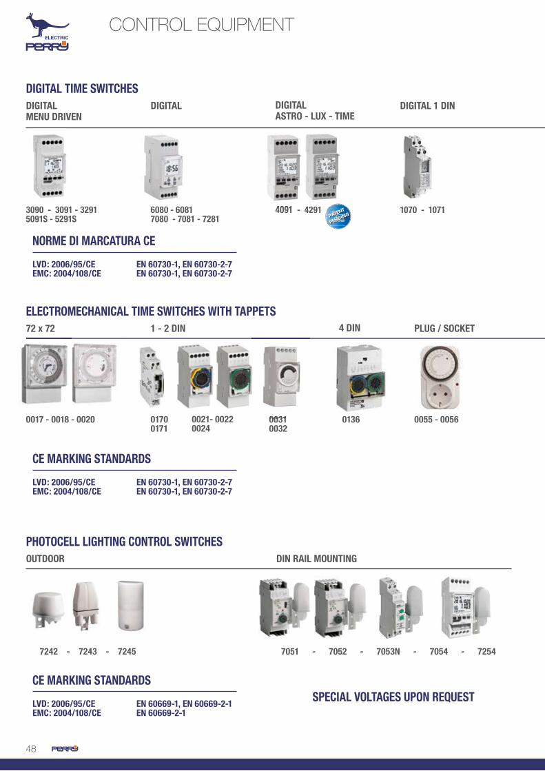
48
CONTROL EQUIPMENT
3090 - 3091 - 3291 5091S - 5291S
0017 - 0018 - 0020 0055 - 0056
7242 - 7243 - 7245 7051 - 7052 - 7053N - 7054 - 7254
4091 - 4291
01360170 0171
0021- 0022 0024
6080 - 60817080 - 7081 - 7281
1070 - 1071
DIGITAL TIME SWITCHES
ELECTROMECHANICAL TIME SWITCHES WITH TAPPETS
PHOTOCELL LIGHTING CONTROL SWITCHES
SPECIAL VOLTAGES UPON REQUEST
NORME DI MARCATURA CE
LVD: 2006/95/CE EN 60730-1, EN 60730-2-7EMC: 2004/108/CE EN 60730-1, EN 60730-2-7
CE MARKING STANDARDS
LVD: 2006/95/CE EN 60730-1, EN 60730-2-7EMC: 2004/108/CE EN 60730-1, EN 60730-2-7
CE MARKING STANDARDS
LVD: 2006/95/CE EN 60669-1, EN 60669-2-1EMC: 2004/108/CE EN 60669-2-1
DIGITAL MENU DRIVEN
72 x 72
OUTDOOR DIN RAIL MOUNTING
DIGITAL
1 - 2 DIN
DIGITAL 1 DIN
PLUG / SOCKET
DIGITALASTRO - LUX - TIME
4 DIN
4091 - 4291
0031 00320031

4949
0012D15 - 0016D15
1051 - 1061 - 1066 - 1062 - 1067
1080/M - 1280/M 1081/M - 1281/M0012D15/M230 0016D15/M230
0022/D15 - 0024/D15 RXDCF77RXGPS01
KTMP2KTMP4
EMD01AUSB01
STAIRCASE TIMERS
CE MARKING STANDARDS
LVD: 2006/95/CE EN 60669-1, EN 60669-2-3, EN 60669-2-1EMC: 2004/108/CE EN 60669-2-1
STAIRCASE TIMERS
DIGITALI WITH TAPPETS 2 DIN
DIGITAL WITH TAPPETS 72 x 72
MODULES INDUSTRIAL TYPE
ACCESSORIES
ONCE AGAIN FIRST
since 1975 the first Italian manufacturer of time switches
1975 Art. 0021-0022-0024The first time switch with tappets in two DIN modules with front disk.
Art. 3090-3091-3291The first daily-weekly-yearly digital time switch.2007
Art. 4091-4291The first switch configurable as astronomical-twilight-time switch.2011
Art. 0022/D15-0024/D15The first digital time switch with tappets and with 15’ programming on the weekly model.
1995
Art. 0031-0032The first time switch with tappets in two DIN modules with front disc and with ON / OFF interval of 15’.
2016

50
CONTROL EQUIPMENTDIGITAL TIME SWITCHES WITH MENU DRIVEN PROGRAMMING
• Navigation menu for easy and intuitive programming• Relay with ZERO CROSSING to increase its lifetime and the power of the connected load.• Holiday Programs: You can set one or more periods during the year and also between two
years.• Minimum Intervention: 1 second• Memory capacity: 64 ON-OFF programs • Power reserve: 6 years thanks to the lithium battery.• Product warranty management: the internal clock is activated at first installation.• Multilanguage menu: 11 languages available.• MAINTENANCE mode: You can set a countdown (in hours) at the end of which a warning
will appear on the display.• Backlit display for perfect visibility in all conditions.• Ready for EMD programming key to upload and / or download programs from a time
switch to another.
SPECIAL FEATURES
The Perry menu driven time switches are characterized by ease of programming, versatility and performance.The four keys enable simple and intuitive navigation in the menu displayed on the backlit two text lines LCD display.The internal calendar allows the execution of programs even only in certain periods of the year, and, with the ability to handle the holidays, the set programs can be interrupted in one or more periods also between two different years (eg. New Year holiday program).The internal lithium battery allows to store programs and time and date settings up to 6 years also without mains connection.With these time switches 64 ON-OFF programs can be memorized, choosing between standard, random, cyclical and holidays programs.The range includes versions with 1 and 2 channels, daily and weekly, ready for the use of theprogramming key. In addition, the S versions offers synchronization with GPS receivers or DCF receivers with Frankfurt time.The programming key 1PR EMD01 supplied separately, allows the transfer of data from one device to another or the input of programs executed by a PC, avoiding waste of time and mistakes.For time absolute accuracy, two versions are available (1IO 5091S and 1IO 5291S) that can be synchronized with the radio time signal from Frankfurt or with a GPS receiver which allows to install the device anywhere in the world.
MAIN FEATURESHigh-contrast LCD display for excellent visibility in all conditions thanks to backlight
Clear display of the status of each contact
Wide choice of programs: standard, cyclic, random and holiday
GPS or DCF77 signal receiving indicator
Hinged plastic cover
1-2 changeover contacts
1 / 2 external inputs for the connection of one or more remote commands, for example: switches and push buttons.
Permanent or temporary manual override, operated directly with a single touch
1 / 2 external inputs for connection of DCF77 or GPS receiver (for 5091S and 5291S versions)
Sealable cover and keypad lock to prevent tampering by unauthorized personnel
Input for programming Key to run, copy or save programs
Terminals for cables up to 6 mm²
backlit display

51
MEMORY CAPACITY
ACCESSORIES
The menu driven time switch can memorize up to 64 different programs (matchable in groups of days): Standard programs, random programs, cyclic programs, holiday programs.The different types of programs are executed according to a different degree of priority.
MAXIMUM PRIORITY
MANUAL OVERRIDE
EXTERNAL INPUT
EMD EXTERNAL MEMORY
HOLIDAY PROGRAM
STANDARD PROGRAM
RANDOM / CYCLIC PROGRAM
Standard programON 19:00 - OFF 22:00P01Standard programON 00:00 - OFF 06:00P02
Random programON 20:00 - OFF 00:00P03
Cyclic programON 19:00 - OFF 22:00P04
Cyclic programON 02:00 - OFF 06:00P05
Random programON 04:00 - OFF 06:00P06
All input programs from P01 AP06 are simultaneously active.
The relay outputs are activated in accordance with the established priorities.
18:00 19:00 20:00 22:00 00:00 02:00 04:00 06:00 08:00
18:00 19:00 20:00 22:00 00:00 02:00 04:00 06:00 08:00
18:00 19:00 20:00 22:00 00:00 02:00 04:00 06:00 08:00
18:00 19:00 20:00 22:00 00:00 02:00 04:00 06:00 08:00
18:00 19:00 20:00 22:00 00:00 02:00 04:00 06:00 08:00
STD
STD
STDP01
P03
P06
P04 P05
P02
Programming key to transfer programs from a time switch to another or from PC.
Programming software to create quickly programs on the PC even complex ones and then download them on the switch time via the programming key.
The antenna receiver of the time signal transmitted from the atomic clock in Frankfurt (1PARXDCF77) increases the digital clock accuracy.
The GPS antenna (1PA RXGPS01), receives the time from the Global Position System and allows to get a more accurate value than terrestrial broadcasts and can be placed anywhere in the World.
1PR EMD01 “EMD” programming key
1PR AUSB01 USB adaptor for “EMD” key

52
TECHNICAL SPECIFICATIONS1IO 3090 3091 3291 5091S 5291S
Daily – monthly – yearly programmingWeekly – monthly – yearly programmingOutput channels n. 1 1 2 1 2
External inputProgramming key opz. opz. opz.Synchronizable with DCF antennaSynchronizable with GPS antennaProgramming software for PC
CONTROL EQUIPMENTDIGITAL TIME SWITCHES WITH MENU DRIVEN PROGRAMMING
Power supply voltage 230V a.c. 50 - 60HzContact rated data potential-free NC contact
16 (2) A / 250V a.c.Limited current NO contactzero crossing 16 (10) A / 250V a.c.
Max program number (ON-OFF) 64 (matchable in blocks of days) ON - OFF minimum connection time 1 secondDisplays 1” 1/3 backlit LCD display Max. commutable power 3500 VA (for individual contact) Power: Incandescent LPs 2300 W Power: Fluorescent tube LPs, not compensated
1000 W
Power: Parallely comp. fluorescent tube LPs 500W (tot capacity 70 μF) Power: Compact, fluorescent LPs 600W Max cross-section of wires to terminals
6 mm2
Protection degree (IP) IP 20 - IP 40 (on rear of switchboard) Type of output terminals with captive screw Insulation class II ON / OFF relay signalling ON / OFF in LCD displayCharge reserve 6 yearsType of reserve LITHIUM battery Time tolerance + - 0.5 sec/day Operating temperature limits 0°C / +50°C Storing temperature -10°C / +65°C Type of installation DIN rail / on rear of switchboard Housing thermoplastic - grey RAL 7035Type of use civil / tertiary / industrialControls multifunction keys (menu programming)
confirmation keyClock setting accuracy digital for hours / minutesDaylight saving time change automatic Programming menu driven - programs protected in EEPROMDimensions (L x W x H) mm 35 x 60 x 90

53
PROGRAMMING MENUThe programming of the time switch is simplified by the navigation menu. In fact, by acting on just four keys you can program 4 different types of interventions and check those already stored, in a simple and intuitive way.You can edit or delete individual programs, and analyze how long the connected loads have been working as well as many other functions such as copying or saving programs from the programming key.
1IO 3090Menu driven daily-yearly time switch 1 channel - 2 DIN
1IO 3091Menu driven weekly-yearly time switch 1 channel - 2 DIN
1IO 3291Menu driven weekly-yearly time switch 2 channels - 2 DIN
1IO 5091SMenu driven weekly-yearly time switch 1 channel with programming key - synchronizable with DCF and/or GPS time signal - 2 DIN
1IO 5291SMenu driven weekly-yearly time switch 2 channels with programming key - synchronizable with DCF and/or GPS time signal - 2 DIN
CHANNEL (Only two-channel)
AUTOPERMANENT ON/OFFTEMP ON/OFF
Manualforcing
- SINGLE PROGR- ALL PROGR- HOLIDAYS
Deletion
- CHECK- EDIT- DELETE
ListPROGRAMS
ENTERING- PROGRAM NO.- CHANNEL (Only two-channel)
- TIME OFF HH:MM:SS- DAY AND MONTH OFF- TIME ON HH:MM:SS- DAY AND MONTH ON
CHECKEDITCOPYDELETE
ProgramHOLIDAYS
ENTERING- PROGRAM NO.- CHANNEL (Only two-channel)
- DAY (Only weekly)
- TIME ON HH:MM:SS- TIME OFF HH:MM:SS- TIME ON- TIME OFF- END/YEARLY
CHECKEDITCOPYDELETE
ProgramCYCLICAL
ENTERING- PROGRAM NO.- CHANNEL (Only two-channel)
- DAY (Only weekly)
- TIME ON HH:MM:SS- TIME OFF HH:MM:SS- END/YEARLY
CHECKEDITCOPYDELETE
ProgramSTANDARD/RANDOM
STANDARD PROGRANDOM PROGCYCLICAL PROGHOLIDAY PROGPROG LISTDELETEMANUALOPTIONS
Menu
ITALIANENGLISHGERMANFRENCHSPANISHSWEDISHPORTUGUESEDUTCHPOLISHRUSSIANGREEK
Languages
- EJEa- EXECUTES FROM EMD- SAVES ON EMD- COPY TO CLOCK- READS EMD- SAVE ONLY HOLIDAYS- COPY ONLY HOLIDAYS- DELETE EMDCUTARDES DE EMD
EMD externalFlash Memory
DAYS 0000
Warranty
- FIXED ON- FIXED OFF- TIMED 6SEC
Displaylighting
C1 000000C2 000000(Only two-channel)
Hour counterMaintenance
C1 000000C2 000000(Only two-channel)
CHANNEL (Only two-channel)
permanent ON/OFFTEMPORARY ON/OFFTIMER ON/OFF
External input
YEARMONTHDAYTIME hh:mmTIME CHANGEDAYLIGHT-SAVING/SOLAR TIME
Date / Time
LANGUAGEDATE/TIMEEXT INPUTMAINTENANCEHOUR COUNTERLIGHTINGWARRANTY
Options
Options
Features are available exclusively in the presence of EMD key (option)

54
CONTROL EQUIPMENTDIGITAL TIME SWITCHES WITH MENU DRIVEN PROGRAMMING
The 1IO SW001 programming software allows you to set programs quickly and conveniently on a computer.The programs, once created, can be printed, saved to a file, sent by e-mail or transferred to the time switch via the EMD01 memory key.The transfer of the programs on your Memory Key is made via the USB adapter 1PR AUSB01.
1PR EMD01 “EMD” programming key
External memory to upload / download programs
1PR AUSB01 USB adapter for “EMD” key
USB adapter to connect the “EMD” programming key to the PC and upload programs
1IO SW001 Programming software for PC
It allows the programming on your computer. The created programs can be saved, sent via e-mail, printed or transferred to the time switch via the “EMD” programming key.
ACCESSORIES
PROGRAMMING SOFTWARE

55
DCF TIME SIGNAL RECEIVER
GPS TIME SIGNAL RECEIVER
Power supply 230V a.c. 50/60Hz Wall-mounted or pole installation BUS output signalProtection degree IP 65Wiring with shielded cablediameter 7-11mmAnti-UV opaline housigwiring with cables up to 2.5 mm2
Can be connected to max no. 10 time switchesLED intervention signallingDimensions (L x W x H) 72 x 37.5 x 147 mm
1PA RXGPS01 Satellite GPS time signal receiver for synchronized time switches
1PA RXDCF77 Time signal receiver from Frankfurt for synchronized time switches
Power supply 230V a.c. 50/60Hz Wall-mounted or pole installation BUS output signalProtection degree IP 65Wiring with shielded cablediameter 7-11mmAnti-UV opaline housingwiring with cables up to 2.5 mm2
Can be connected to max no. 10 time switchesLED intervention signallingDimensions (L x W x H) 72 x 37.5 x 147 mm
The accuracy of time synchronization together with the minimum programming terms (seconds) allow the installation of the product for the activation of activity beginning/end signals in: schools, factories, offices, etc.
The DCF77 station, which is managed by the Physikalisch-Technische Bundesanstalt, is widely used in various countries. The abbreviation means: D=Deutschland (Germany), C=long-wave signal, F=Frankfurt, 77=Frequency equalling 77.5 kHz.The time reference is kept by an atomic clock and spread from Mainflingen, about 25 km far from Frankfurt. The signal can be received from a 2000 km distance. Two independent 50 kW transmitters are used to assure service continuity.
Some clocks receive the time by the Global Positioning System, which offers a more precise value with respect to terrestrial transmissions. The GPS system combines the time supplied by different atomic clocks installed in system satellites and a network of terrestrial stations; it establishes and corrects errors. As time is simultaneously obtained by different sources, the clock can automatically compensate propagation delays and other problems, by reaching an accuracy that is lower than a microsecond in optimal conditions.

56
CONTROL EQUIPMENTDIGITAL TIME SWITCHES
SPECIAL FEATURES
PROGRAMMING EXAMPLES
Automatic gate opening at h. 8:00 and closing at h. 9:00
Control box time profiles in zone systems
• Large 1 “1/3 display • Minimum ON / OFF Programming 1 second• Programming even past midnight, between different days• Memory capacity: 20 ON / OFF programs coupled in blocks of days• EEPROM memory to maintain the programs beyond the power reserve• Power reserve: 15 days• Hinged protective cover• Sealable protective cover• Terminals 6 sq.m.• Terminals with captive screws
KEY PROGR = programming input = selection of desired program 1 or 2DAY = selection of day / group of days = data input ON status / OFF statusPROGR = programming end Possibility of manual override of ON / OFF permanent status
The new range of time switches are a great economic technical solution for time management in different applications.These time switches consist of products that are easy to read thanks to 1 “1/3 backlit LCD display with large numbers, which thanks to the optimal contrast, allows to visualize immediately the load status as well as the day, the current time and if a manual intervention was selected. The performance offered make them suitable for use in various applications to run programs with interventions lasting a minimum of one second, up to interventions that can last up to a week. Thanks to the internal memory, you can save up to 20 ON-OFF programs that, in weekly versions, can be grouped into groups of days or different for each day of the week. The wide offer of time switches allows you to find always the product to fit your needs. They are available in daily and weekly versions, with one or two contacts, with or without the daylight saving time change.
DAY1 - 2 - 3 - 4 - 5P01
DAY1 - 2 - 3 - 4 - 5P01
1
2
DAY1 - 2 - 3 - 4 - 5P02
DAY1 - 2 - 3 - 4 - 5P02
DAY6 - 7P03
1 sec.ON
OFF8:00
1 sec.ON
OFF9:00
ON
OFF
ON
OFF
ON
OFF
6:00 8:30
17:00 23:00
6:00 23:00
backlit display

57
1IO 7080Digital daily time switch with automatic daylight saving time change 1 channel - 2 DIN
1 potential-free changeover contact
1 potential-free changeover contact
2 potential-free changeover contacts
1 potential-free changeover contact
1 potential-free changeover contact
TIME SWITCHES WITH AUTOMATIC DAYLIGHT SAVING TIME CHANGE
1IO 7281Digital weekly time switch with automatic daylight saving time change 2 channels - 2 DIN
1IO 7081Digital weekly time switch with automatic daylight saving time change 1 channel - 2 DIN
1IO 6081Digital weekly time switch without automatic daylight saving time change 1 channel - 2 DIN
1IO 6080Digital daily time switch without daylight automatic saving time change 1 channel - 2 DIN
TIME SWITCHES WITHOUT AUTOMATIC DAYLIGHT SAVING TIME CHANGE
DIGITAL DAILY TIME SWITCH MODULES WITH AUTOMATIC DAYLIGHT SAVING TIME CHANGE
1IO 1080/MDigital daily time switch module with automatic daylight saving time change 1 channel
1IO 1280/MDigital daily time switch module with automatic daylight saving time change 2 channels
1IO 1081/M Digital weekly time switch module with automatic daylight saving time change 1 channel
1IO 1281/MDigital weekly time switch module with automatic daylight saving time change 2 channels
Legenda:Pin 1 VDD (alimentazione)Pin 2 uscita relè 1Pin 3 uscita relè 2Pin 4 massa GND
1234
Pin 1 VDD (power supply)Pin 2 relay output 1Pin 3 relay output 2Pin 4 GND earth

58
CONTROL EQUIPMENTDIGITAL TIME SWITCHES
TECHNICAL SPECIFICATIONSWith automatic daylight saving time change Without automatic daylight saving time change
1IO 7080 7081 7281 6080 6081
Daily programmingDaily - weekly programmingOutput channels n. 1 1 2 1 1
Automatic daylight saving time changeON-OFF minimum time 1 secondBacklit display
Power supply voltage 230V a.c. 50 - 60HzContact rated data potential-free NC contact
16 (2) A / 250V a.c.Max program number (ON-OFF) 20 (matchable in blocks of days) ON - OFF minimum connection time 1 secondDisplays 1” 1/3 backlit LCD display Max. commutable power 3500 VA (for individual contact) Power: Incandescent LPs 2300 W Power: Fluorescent tube LPs, not compensated
1000 W
Power: Parallely comp. fluorescent tube LPs 500W (tot capacity 70 μF) Power: Compact, fluorescent LPs 600W Max cross-section of wires to terminals
6 mm2
Protection degree (IP) IP 20 - IP 40 (on rear of switchboard) Type of output terminals with captive screw Insulation class II ON / OFF relay signalling ON / OFF in LCD displayCharge reserve max 15 daysType of reserve NiMH rechargeable battery Time tolerance + - 0.5 sec / day Operating temperature limits 0°C / +50°C Storing temperature -10°C / +50°C Type of installation DIN rail / on rear of switchboard Housing thermoplastic - grey RAL 7035Type of use civil / tertiary / industrialControls programming keys, ON / OFF manual
override keyClock setting accuracy digital for hours / minutesDaylight saving time change for 4 geographic ares Digital programming for hours / minutes / secondsDimensions (L x W x H) mm 35 x 60 x 90

59
The large backlit display allows for a clear and immediate reading of the relays status, current time and day and any manual override.
ICONS DISPLAY
WIRING DIAGRAM
DISPLAY AND KEYS FUNCTION
DIMENSIONS (mm)
Day programming
LCD display
Channel 2 manual override
Reset
Confirm
Channel 1 manual override
Programming key
Hours, minutes, seconds programming
Channel 1 ON
Channel 2 OFF
Manual override
Week days (only weekly version)
N. program running
1 2 3 4 5
6 7 8 9 10
90
35 60
Front side
1 2 3 4 5
6 7 8 910
C1
L
N230 Vac
Range:1IO 6080 (daily, 1 channel)1IO 6081 (weekly, 1channel)Range:1IO 7080 (daily, 1 channel, +/- 1hr auto)1IO 7081 (weekly, 1channel, +/- 1hr auto)
1 2 3 4 5
6 7 8 9 10
C1
C2
L
N230 Vac
Range:1IO 7281 (weekly, 2 channels, +/- 1hr auto)

60
The battery can be replaced WITHOUT UN-INSTALLING THE PRODUCT • Large LCD display with WHITE LED backlight• Memory capacity: 45 ON+OFF programs • Hinged and sealable cover • 6 mm2 terminals • Terminals with captive screws • Simple, intuitive programming • Charge reserve: 6 years • Closing of the contact with ZERO CROSSING logic • Minimum intervention: 1 minute
The new range of ASTRO-LUX-TIME switches represents the solution for managing loads based on astronomical cycle, time or brightness and/or their combinations. The INNOVATIVE solution, one product for the following functions: • Astronomical switch • Time switch • Twilight switch The ASTRO-LUX-TIME switches can run ASTRONOMICAL, TWILIGHT and TIME PROGRAMS or COMBINATIONS OF THESE TO MEET DISPARATE FUNCTIONAL REQUIREMENTS.The ASTRO-LUX-TIME switches are a patent.
SELECTIONASTRO/LUX/TIME
DATAinput coordinates
available in the instruction manual or on smartphone
OFFSET (IF ANY)anticipation / delay
ON-OFF
DISPLAY OF OPERATING PRODUCT
It’s an astronomical switch
ASTRO LUXIt’s a twilight
switch
TIMEit’s a time
switch
CONTROL EQUIPMENTASTRO-LUX-TIME SWITCHES
SPECIAL FEATURES
PROGRAMMING
The only multifunctional product!
The battery can be replaced WITHOUT UN-INSTALLING THE PRODUCT • Large LCD display with WHITE LED backlight• Memory capacity: 45 ON+OFF programs • Hinged and sealable cover • 6 mm• Terminals with captive screws • Simple, intuitive programming • Charge reserve: 6 years • Closing of the contact with ZERO CROSSING logic • Minimum intervention: 1 minute
The new range of ASTRO-LUX-TIME switches represents the solution for managing loads based on astronomical cycle, time or brightness and/or their combinations. The INNOVATIVE solution, one product for the following functions: • Astronomical switch • Time switch • Twilight switch The ASTRO-LUX-TIME switches can run ASTRONOMICAL, TWILIGHT and TIME PROGRAMS or COMBINATIONS OF THESE TO MEET DISPARATE FUNCTIONAL REQUIREMENTS.The ASTRO-LUX-TIME switches are a
CONTROL EQUIPMENTASTRO-LUX-TIME SWITCHES
SPECIAL FEATURES
backlit display

61
1IO 4091Astronomical twilight time switch 1 channel - 2 DIN
1IO 4291Astronomical twilight time switch 2 channels - 2 DIN
1PR EMD01 “EMD” programming key
External memory key for downloading and uploading programs
1PR 6092 Outdoor cadmium-free probe
Installation outdoors on wall and/or pole Connection with cables measuring between 0.75 and 2.5 mm2 Cabling with 4-8 mm shielded cable
UV-resistant opal housing Protection degree IP 20 Dimensions of sensor (L x W x H) 28 x 48 x 56 mm
The probe is not included in the packing. it must be purchased separately.
ACCESSORIES
SHOP SIGNBOARD - Operation with twilight / time / Astro logic
CONDOMINIUM GATE OPENING - Operation with time logic
PUBLIC / SQUARE / PARKING LIGHTING - Operation with astronomical logic and daytime intervention in twilight mode in case of storm
TWILIGHTON
TIME h 7:30ON
ASTRONOMICON
TIME h 6:00ON
TIME h 22:00OFF
TIME h 9:00OFF
ASTRONOMICOFF
ASTRONOMICOFF
1
2
3
ON
OFF22:00 6:00SUNSET SUNRISE
ON
OFF9:007:30
ON
OFFSUNRISESUNSET SUNSET12:00 14:00

62
CONTROL EQUIPMENTASTRO-LUX-TIME SWITCHES
TECHNICAL SPECIFICATIONS
Power supply 230V a.c.+/-10%, 50HzNominal data contats 16 (2) A / 250V a.c. Max number of programs (ON+OFF) 45 Minimum ON-OFF engaging time 1 minuteDetails shown on 1" 1/3 backlit LCD displayMax switching power 3500 VA (for each contact)Power: LP incandescence 2300 W Power: LP fluorescent tubes uncompensated 1000 W Power: LP fluorescent tubes in parallel, 500W (total capacity 70 μF) compensatedPower: compact LP fluorescent tubes 600W Max size of cables at terminals 6 mm2 Protection rating (IP) IP 20 - IP 40 (rear swithcboard) Type of output terminals with captive screwsInsulation class II Relay ON / OFF signal ON / OFF on LCD display Power reserve 6 yearsType of reserve CR2032 replaceable batteryTime tolerance ± 0.5 sec / day Operating temperature range -20°C / +60°C Storage temperature -30°C / +80°CType of installation DIN rail / rear switchboardHousing thermoplastic - RAL 7035 grey Type of use civil / service / industrialControls programming keys, ON / OFF manual override key Precision time setting digital in hours / minutes Cambio ora legale automatica for 4 geographic areasDigital programming in hours / minutesDimensioni (L x W x H) mm 35 x 60 x 30
With automatic daylight saving time change
1IO 4091 4291
Number of output contacts 1 2Weekly programmingAutomatic summer time changeBacklit displayReplaceable batteryAstronomicalTwilightTimeInput for twilight sensorTwilight sensor 1PR 6092 accessory 1PR 6092 accessoryKey lock

63
The large backlit display allows for a clear and immediate reading of the relays status, current time and day and any manual override.
UNIQUE PRODUCTfor all necessities
REPLACEABLE BATTERYfrom front (Time saving!)
KEY (option)to transfer the programs
BACKLIT
POSSIBILITY TO ANTICIPATE / DELAY astronomical interventions
ZERO CROSSING
Channel 1 ON / OFF
Manual overrideChannel 2 ON / OFF
Week days
Date
Time
Operation mode
menù
Down
ok
Up
Front Side 1IO 4091 1 channel 1IO 4291 2 channels
90
35 60
DISPLAY AND KEYS FUNCTION
DIMENSIONS (mm) WIRING DIAGRAM
REPLACEABLE BATTERY FROM FRONT

64
ESEMPIO DI PROGRAMMAZIONEON dalle ore 6,00 OFF alle ore 8,301 - premere il tasto P per accedere alla programmazione
degli interventi2 - con i tasti e selezionare l’ora di intevento: 063 - con i tasti cavaliere , , e attivare i quarti
d’ora relativi alle ore in cui si intende attivare il relèfino ad arrivare alle ore 8,30
- visualizzazione ore e minuti- indicazione stato del
relè ON/OFF- attivazione funzionamento
manuale- giorni della settimana
vetrino imperdibile
CONTROL EQUIPMENTDIGITAL TIME SWITCHES 1 DIN
The programming process makes these digital models completely similar to electromechanical modelswith tappets,additionally with:• Digital accuracy of intervention times• Possibility to program 96 ON / OFF interventions in daily model and 672 interventions in weekly
model – ON / OFF interventions every 15 minutes• Programming keys are clear to identify and handle in the front of the product • Models with automatic standard time / daylight saving time change according to European calendar
1IO 1070 Digital daily time switch with automatic standard time / daylight saving time change - 1 DIN
1IO 1071 Digital weekly time switch with automatic standard time / daylight saving time change - 1 DIN
ON from 6:00am OFF at 8:30am1- press the key P to access
intervention2- with the keys and select the
time of intervention: 063- with rider keys ,
,
, and activate the quarters of the hour concerning the hours in which you want to activate the relay until reaching 8:30am
• display of hours and minutes• ON / OFF relay status indicator• manual operation activation• week days
Captive glass
DISPLAY AND KEYS FUNCTION TECHINCAL SPECIFICATIONS
PROGRAMMING EXAMPLE
1 potential-free changeover contact ON / OFF minimum 15’
1 potential-free changeover contact ON / OFF minimum 15’
Power supply voltage 230V a.c. 50 - 60Hz Power supply voltage 16 (2) A / 250V a.c. Max program number (ON-OFF) 96 (daily) / 672 (weekly) ON - OFF minimum connection time 15 minutesDisplays ¼“ LCD display Max commutable power 3500 VA (for individual contact) Power: Incandescent LPs 2300 W Power: Fluorescent tube LPs, not compensated
1000 W
Power: Parallely comp. fluorescent tube LPs
500W (tot capacity 70 μF)
Power: Compact, fluorescent LPs 600W Max cross-section of wires to terminals
2.5 mm2
Protection degree (IP) IP 20IP 40 (on rear of switchboard)
Type of output terminals with captive screw Insulation class II ON / OFF relay signalling ON / OFF in LCD displayCharge reserve max. approx. 15 daysType of reserve NiMH rechargeable batteryTime tolerance + - 0.5 sec/dayOperating temperature limits 0°C / +50°C Storing temperature -10°C / +50°C Type of installation DIN rail / on rear of switchboardHousing thermoplastic - grey RAL 7035 Type of use civil / tertiary / industrial Controls programming keys ON / OFF manual function key Clock setting accuracy digital for hours / minutesDaylight saving time change automatic (for items 1070 and 1071)Dimensions (L x W x H) mm 17.5 x 60 x 90

65
The programming process makes these digital models completely similar to electromechanical modelswith tappets, additionally with:• digital accuracy of intervention times• possibility to program 96 ON / OFF interventions in daily model and 672 interventions in
weekly model – ON / OFF interventions every 15 minutes• programming keys are clear to identify and handle in the front of the product • Installation in rear of panel with accessory (1PA KTMP2 - option)
1IO 0024/D15Digital weekly time switch with tappets and display - 2 DIN
1IO 0022/D15Digital daily time switch with tappets and display - 2 DIN
DISPLAY AND KEYS FUNCTION TECHINCAL SPECIFICATIONS
1 potential-free changeover contact ON / OFF minimum 15’
1 potential-free changeover contact ON / OFF minimum 15’
Note: all products can be installed in rear of switchboard with accessory 1PA KTMP / 2 (option)
Power supply voltage 230V a.c. 50 - 60Hz Power supply voltage 16 (2) A / 250V a.c. Max program number (ON-OFF) 96 (daily) / 672 (weekly) ON - OFF minimum connection time 15 minutesDisplays 1” round LCD displayMax commutable power 3500 VA (for individual contact) Power: Incandescent LPs 2300 W Power: Fluorescent tube LPs, not compensated
1000 W
Power: Parallely comp. fluorescent tube LPs
500W (tot capacity 70 μF)
Power: Compact, fluorescent LPs 600W Max cross-section of wires to terminals
2.5 mm2
Protection degree (IP) IP 20 - IP 30 (with terminal covers)IP 40 (on rear of switchboard)
Type of output terminals with captive screwInsulation class II ON / OFF relay signalling ON / OFF in LCD displayCharge reserve max 15 daysType of reserve NiMH rechargeable batteryTime tolerance + - 1 sec/day Operating temperature limits 0°C / +50°C Storing temperature -10°C / +50°C Type of installation DIN rail / wall-mounted / on rear of
switchboardHousing thermoplastic - grey RAL 7035Type of use civil / tertiary / industrial Embedded controls programming keys / ON / OFF manual function
key Clock setting accuracy digital for hours / minutesDimensions (L x W x H) mm 35 x 60 x 128

66
Programming as a clock with tappets
Accurate like a digital
1IO 0016D15Digital weekly time switch with tappets and display 72x72
1IO 0012D15Digital daily time switch with tappets and display 72x72
1IO 0012D15/M230 Digital daily time switch module with tappets and display 60x60 - 230V 50/60Hz
1IO 0016D15/M230Digital weekly time switch module with tappets and display 60x60 - 230V 50/60Hz
CONTROL EQUIPMENTDIGITAL TIME SWITCHES WITH TAPPETS 72 X 72
1 potential-free changeover contact ON / OFF minimum 15’
1 potential-free changeover contact ON / OFF minimum 15’
DISPLAY AND KEYS FUNCTION TECHINCAL SPECIFICATIONS
Power supply voltage 230V a.c. 50 - 60Hz Contact rated data 16 (2) A / 250V a.c. Max program number (ON-OFF) 96 (daily) / 672 (weekly) ON - OFF minimum connection time 15 minutesDisplays round LCD displayMax commutable power 3500 VA (for individual contact) Power: Incandescent LPs 2300 W Power: Fluorescent tube LPs, not compensated 1000 W Power: Parallely comp. fluorescent tube LPs 500W (tot capacity 70 μF) Power: Compact, fluorescent LPs 600W Max cross-section of wires to terminals 2.5 mm2
Protection degree (IP) IP 40 (wall-mounted - on rear of switchboard)
Type of output terminals with captive screwInsulation class II ON / OFF relay signalling ON / OFF in LCD displayCharge reserve max. approx. 15 days Type of reserve NiMH rechargeable battery Time tolerance + - 1 sec / dayOperating temperature limits 0°C / +50°C Storing temperature -10°C / +50°C Type of installation wall-mounted / on rear of
switchboard / recessedHousing thermoplastic - grey RAL 7035Type of use civil / tertiary / industrial Controls programming keys - reset key ON
/ OFF manual function keyClock setting accuracy digital for hours / minutesDimensions (L x W x H) mm 72 x 67.5 x 101

67
Nota: Art. 0012D15 - 0016D15 - 0017 - 0018 - 0020 can be installed in rear of switchboard with accessory 1PA SG001
CONTROL EQUIPMENTELECTROMECHANICAL TIME SWITCHES FOR WALL-MOUNTING, REAR SWITHCBOARD AND DIN RAIL
DISPLAY AND KEYS FUNCTION TECHINCAL SPECIFICATIONS
Selector fixed ON / timer / fixed OFF
1IO 0017Daily time switch with tappets without charge reserve – 72x72
1IO 0018Daily time switch with tappets with charge reserve – 72x72
1IO 0020Weekly time switch with tappets with charge reserve – 72x72
1 potential-free changeover contact ON / OFF minimum 15’
1 potential-free changeover contact ON / OFF minimum 15’
1 potential-free changeover contact ON / OFF minimum 120’
OFFON
ON
FIXED ON FIXED OFFHOUR PROGRAMMING
84 tappets
Hours index (int. 2 h)
Day indicator
WEEKLY
Minutes index (int. 15’)
96 tappets
DAILY
REAR SWITHCBOARD AND DIN RAILREAR SWITHCBOARD AND DIN RAIL
1IO 0017
REAR SWITHCBOARD AND DIN RAIL
Power supply voltage 230V a.c. 50 - 60Hz Contact rated data 16 (2) A / 250V a.c. Max program number (ON-OFF) 96 (daily) - 84 (weekly) ON-OFF minimum switching time 15 minutes (daily) 120 minutes approx (weekly) Visualizations mechanical tappets ring Max commutable power 3500 VA Max cross-section of cables to terminals 2,5 mm2
Protection degree (IP) IP 30Type of output terminals with captive screws Insulation class II Charge reserve 100 hours ± 15%Type of reserve NiCd rechargeable batteryTime tollerance ± 1 sec / day Operating temperature limits -10°C / +50°C Storing temperature -10°C / +50°C Type of installation DIN rail / wall mountedHousing thermoplastic – RAL 7035 greyType of use civil / tertiary / industrialControls mechanical tappets ring selector switch: Fixed ON / timer position / fixed OFFClock indication only on daily versionsClock setting accuracy mechanical with reference indexProgramming mechanical key ring (blocks 15’ / 120’)Dimensions (L x W x H) mm 72 x 48 x 101

68
CONTROL EQUIPMENTELECTROMECHANICAL TIME SWITCHES FOR DIN RAIL MOUNTING
Possibility to set hours and minutes
Disc
Hole to insert tool (screwdriver or pencil) to rotate the disc
Minute indication
HourindicatorON / OFF
manual control
OFFON
NB: turn clockwise
1IO 0170Daily time switch with tappets and without charge reserve - 1 DIN1 potential-free changeover contact ON / OFF minimum 15’
1IO 0171Daily time switch with tappets and charge reserve - 1 DIN1 potential-free NO contact ON / OFF minimum 15’
1IO 0021Daily time switch with tappets without charge reserve - 2 DIN 1 potential-free changeover contact ON / OFF minimum 30’
1IO 0022Daily time switch with tappets and charge reserve - 2 DIN1 potential-free changeover contact ON / OFF minimum 30’
1IO 0024Weekly time switch with tappets and charge reserve - 2 DIN1 potential-free changeover contact ON / OFF minimum 210’ (approx 3,5 h)
1IO 0136Weekly and daily time switch with charge reserve - 4 DIN2 potential-free changeover contacts ON / OFF daily minimum 30’, weekly minimum 210’ (approx 3,5 h)
TECHNICAL SPECIFICATIONSDISPLAY AND KEYS
FUNCTION
NOTE: 2 and 4 DIN items can be installed on the rear of the switchboard by means of optional accessories (KTMP2 or KTMP4).
Power supply voltage 230V a.c. 50 - 60HzContact rated data 16 (2) A / 250V a.c.Max program number (ON-OFF) 48 - 96 (art. 0170 / 0171)ON - OFF minimum connection time 30 minutes (daily) 15’ (item 0170 - 0171) approx. 3.5 hours (weekly)Displays mechanical tappets ringMax commutable power 3500 VA (for individual contact)Max cross-section of wires to terminals 2.5 mm2
Protection degree (IP) IP 20 - IP 30 (with terminal covers) IP 40 (on rear of switchboard)Type of output terminals with captive screwInsulation class II Charge reserve approx 150 h max (max 100 h mod. 0171)Type of reserve NiCd rechargeable batteryTime tolerance + - 1 sec/dayOperating temperature limits -10°C / +50°CStoring temperature -10°C / +50°CType of installation DIN rail / wall-mounted / on rear of switchboardHousing thermoplastic - grey RAL 7035Type of use civil / tertiary / industrialControls mechanical tappets ring selector switch: fixed ON / timer positionClock setting accuracy mechanical with reference indexProgramming mechanical key ring Dimensions (L x W x H) mm 1DIN 17.5 x 60 x 128 - 2DIN 35 x 60 x 116 4DIN 70 x 60 x 116
1IO 0170Daily time switch with tappets and without charge reserve - 1 DIN
0170 0171
002100220024
0136

69
CONTROL EQUIPMENTELECTROMECHANICAL TIME SWITCHES FOR DIN RAIL MOUNTING
1IO 0031Daily time switch with tappets without charge reserve – 2 DIN
1IO 0032Daily time switch with tappets and charge reserve – 2 DIN
Possibility to set hours and minutes
Disc
Hole to insert tool (screwdriver or pencil) to rotate the disc
Minute indication
HourindicatorON / OFF
manual control
OFFON
NB: turn clockwise
1 potential-free changeover contact ON / OFF minimum 15’
1 potential-free changeover contact ON / OFF minimum 15’
TECHNICAL SPECIFICATIONSDISPLAY AND KEYS
FUNCTION
NOTE: 0031 and 0032 can be installed on the rear of the switchboard by means of optional accessories (KTMP2 or KTMP4).
Power supply voltage 230V a.c. 50 - 60HzContact rated data 16 (4) A / 250V a.c.Max program number (ON-OFF) 96ON-OFF minimum switching time 15 minutesVisualizations mechanical tappets ringMax commutable power 3500 VA (for every single contact)Max cross-section of cables to terminals 2.5 mm2
Degree protectoin (IP) IP 30Type of output terminals with captive screwsInsulation class II Charge reserve max 150 hours approxType of reserve NiCd rechargeable batteryTime tolerance ± 1 sec / dayOperating temperature limits -10°C / +50°CStoring temperature -10°C / +50°CType of installation DIN rail / wall mounted / rear of switchboardHousing thermoplastic – RAL 7035 greyType of use civil / tertiary / industrialControls mechanical tappets ring selector: timer position / fixed OFFClock setting accuracy mechanical with reference indexProgramming mechanical key ring (15’ blocks)Dimensioni (L x W x H) mm 35 x 60 x 90
2 DIN ELECTROMECHANICAL TIME SWI-TCHES with 15’ minimum ON / OFF interven-tion time.
patent: once again first!

70
CONTROL EQUIPMENTPLUG / SOCKET TIME SWITCHES - ACCESSORIES
1IO 0055Daily time switch, plug/socket Shuko 16 A
Power supply 230V a.c. 50/60HzContacts 16 AMaximum commutable power 3500 VA
Minimum intervention interval 15 minON / TIMER control
1IO 0056Weekly time switch, plug/socket Shuko 16 A
Power supply 230V a.c. 50/60HzContacts 16 AMaximum commutable power 3500 VA
Minimum intervention interval 120 minON / TIMER control
Kit including:2 hooks + finishing front for installing 2 DIN modules on the rear of the switchboard
1PA KTMP2 Kit for installation of 2 DIN modules on rear of switchboard
1PA SG001 Plastic profile for installing 72x72 time switches on rear of switchboard
ACCESSORIES
Kit including:2 hooks + finishing front for installing 4 DIN modules on the rear of the switchboard
1PA KTMP4 Kit for installation of 4 DIN modules on rear of switchboard

71
CONTROL EQUIPMENTSTAIRCASE TIMERS
1IT 1061 Staircase timer, modular 2 DIN
Power supply 230V a.c. +5%-10% 50/60Hz1 polarized NO contact output: 10A / 250 V a.c.Maximum controllable power 2200WTiming adjustable from 1 min to 18 minOperation intended with any number of luminous push buttonsSwitch for Operation with fixed light
ON relay signaling warning lightThe LED is ON3-wire connectionAlso suitable for wall-mountingInstallation on DIN rail and / or wall mountedDimensions (L x W x H) 35 x 60 x 128 mm
L
N230V~
1 2 3
a b
1061
1IT 1061
WIRING DIAGRAMS
1IT 1051
L
N
1 2 3
230V~
1051
1IT 1051Staircase timer, wall-mounted
Power supply 230V a.c. +-10% 50/60Hz1 polarized NO contact output: 16(3) A / 250 V a.c.Power: incandescent LPs 2300WPower: fluorescent LPs 290 WPower: electronic fluorescent LPs 105WAdjustable timing from 30 sec at 7 min +/-10%Restorable
3-wire connectionMax 30 external START and push buttons (also luminous)Fixed light switchWall or panel mounting Cables up to 2.5 mm2
Dimensions (L x W x H) 88 x 55 x 110 mm
Electronic timer switch, can perfectly replace the three-wire electromechanical models made in Germany, Spain, etc
1IT 1066Timer switch with multifunction LCD display for an easy and finer adjustment of the functions
Power supply 230V a.c. 50 / 60Hz1 polarized NO contact output: 16(3) A / 250 V a.c.Power: Incandescent LPs 2300WFluorescent LPs 290 WElectronic fluorescent LPs 105 WAdjustable timing from 1 sec at 99 min to 59 secRestorableStaircase cleaning function 30min (modifiable from 1min to 99 min)
Deactivation push from 15sec to 300secMax 35 luminous push buttonsProtection degree IP 40Fixed relay keyHour counter function for lamp changeInput status display (open / close)Timing shown in the displayTime scale indicators: h m s3- or 4-wire connectionCables from 1 mm2 to 2.5 mm2
Dimensions (L x W x H) 17.5 x 60 x 90 mm
LN
230V~
3 L
4 N
MONTANTE 3 FILI
LN
230V~
3 L
4 N
MONTANTE 4 FILI
1065.2
1IT 1066
3 wire connection 4 wire connection

72
1IT 1062Staircase timer 1 DIN
Power supply 230V a.c. +/- 10%, 50 HzType of output relay with NO single-pole polarized contact 16A / 250V a.c.Time adjustment: from 30 seconds to 20 minutesAbility to activate stair cleaning functionMaximum wire section at terminals: 1 mm² ÷ 6 mm²Protection degree: IP 20Operating temperature limits of module: - 10 °C ÷ +55 °C
Storage temperature limits: - 20 °C ÷ +65 °CType of installation: DIN railMaximum current consumption of illuminated pushbuttons 150mA with overload protectionCE reference standards: LVD/EMC EN60669-2-3 EN60669-2-1Dimensions (L x W x H): 17,5 x 60 x 90 mm
EXAMPLES OF MAXIMUM OPERATING LOADS
Contact closing with zero load and “ZERO CROSSING” method
The relay contacts will open and close only in the instant when the voltage is equal to zero. This method allows to increase the contact lifetime by optimizing the activation and deactivation of the load. It makes it particularly suitable for controlling electronic lamps, LED and energy-saving lamps.
OPERATING MODEST: timed relay with staircase clearing function
L
N230V ~
LN
34
L
N230V ~
LN
34
3 wire connection 4 wire connection
Staircase cleaning
CONTROL EQUIPMENTSTAIRCASE TIMERS
WIRING DIAGRAMS
BUTTON
BUTTON
RELAY
RELAY
YESTERDAY TODAY

73
1IT 1067Multifunction staircase timer 1 DIN
Power supply 230V a.c. +/- 10%, 50 HzType of output relay with NO single-pole polarized contact 16A / 250V a.c.Time adjustment: from 30 seconds to 20 minutesSwitch off warning in the TW and TWI operation modesAbility to activate stair cleaning function in the T and TW operation modesMaximum wire section at terminals: 1 mm² ÷ 6 mm²Protection degree: IP 20
Operating temperature limits of module: - 10 °C ÷ +55 °CStorage temperature limits: - 20 °C ÷ +65 °CType of installation: DIN railMaximum current consumption of illuminated pushbuttons 150mA with overload protectionCE reference standards: LVD/EMC EN60669-2-3 EN60669-2-1Dimensions (L x W x H): 17,5 x 60 x 90 mm
3- DESCRIPCIÓND ELASMO D
TI TIW
ITW
T
TI TIW
ITW
T
TI TIW
ITW
T
TI TIW
ITW
T
TI TIW
ITW
T
TI TIW
ITW
T
45’
>5” <5”
45’
>5” >5”
Relè
Pulsante
T
Relè
Pulsante
<5”
T T
T 15”
15”
15”
15”
300ms300ms
300ms300ms
T
<5”<5”
Relè
Pulsante
T
45’
>5” <5”
45’
>5” >5”
Relè
Pulsante
T
T(selectorgiratorio con 4posiciones)
T
Relè
Pulsante
T
Relè
Pulsante
T
Relè
Pulsante
Relè
Pulsante
15”
300ms300ms
Contact closing with zero load and “ZERO CROSSING” method
The relay contacts will open and close only in the instant when the voltage is equal to zero. This method allows to increase the contact lifetime by optimizing the activation and deactivation of the load. It makes it particularly suitable for controlling electronic lamps, LED and energy-saving lamps.
OPERATING MODEST: timed relay with staircase clearing functionTW: timed, resettable relay with OFF warning and “stairs cleaning” functionTI: timed impulse relay
TIW: timed impulse relay with OFF warningI: impulse ralay (step relay)L: light on
Staircase cleaning
Staircase cleaning
T
TW
TI
TIW
I
L
EXAMPLES OF MAXIMUM OPERATING LOADS
BUTTON
RELAY
BUTTON
BUTTON
BUTTON
BUTTON
BUTTON
BUTTON
BUTTON
RELAY
RELAY
RELAY
RELAY
RELAY
RELAY
RELAY
YESTERDAY TODAY

74
1PR 7243M Spare module for photocell lighting control switch item 7243
Power supply 230V a.c. 50/60HzOutdoor installationOutput 1 polarized NO contact: 16 (2) A / 250Va.c.
Pre-calibrated at the factory at 10 Lux ± 20%Intervention threshold adjustment trimmer, 2 - 200 LuxThreshold signalling LED Anti-UV opaline housingDimensions (L x W x H) 72 x 37.5 x 80 mm
1IC 7243Photocell lighting control switch with replaceable control module for wall-mounting and/or pole installation
Power supply 230V a.c. 50/60HzOutdoor installationOutput 1 polarized NO contact: 16 (2) A / 250Va.c.Connection with cables up to 2.5 mm2
Wiring with shielded cable diameter 7-11 mmPre-calibrated at the factory at 10 Lux ± 20%
Intervention threshold adjustment trimmer, 2 - 200 LuxThreshold signalling LEDAnti-UV opaline housingProtection degree IP 65Dimensions (L x W x H) 72 x 37.5 x 147 mm
Product being particularly suitable to facilitate system maintenance personnel: the control part that can be removed from the base of the contacts allows a quick intervention in the product without disconnecting the load
1IC 7245Photocell lighting control switch model “FEBO” for wall-mounting and/or pole installation
Power supply 230V a.c. 50 / 60HzOutdoor installationOutput 1 polarized NO contact: 16 (2) A/250Va.c.Connection with cables up to 2.5 mm2
Wiring with shielded cable diameter 7-11 mmPre-calibrated at the factory at 10 Lux ± 20%
Intervention threshold adjustment trimmer, 2 - 200 LuxThreshold signalling LEDAnti-UV opaline housingProtection degree IP 65Dimensions (L x W x H) 55 x 45 x 106 mm
The factory 10 LUX calibration prevents difficult interventions by the installer
1IC 7242Photocell lighting control switch for wall-mounting and/or pole installation
Power supply 230V a.c. 50 / 60HzOutdoor installationOutput 1 polarized NO contact: 16 (2) A / 250Va.c.Connection with cables up to 2.5 mm2
Wiring with shielded cable diameter 4-9 mm
Intervention threshold adjustment trimmer, 2 - 200 LuxThreshold signalling LEDAnti-UV opaline housingProtection degree IP 54Dimensions (Ø L x W x H) Ø 82 x 97 x 101 mm
CONTROL EQUIPMENTOUTDOOR PHOTOCELL LIGHTING CONTROL SWITCHES

75
1IC 7051Photocell lighting control switch with adjustment 2-10.000Lux, 2 DIN
Power supply 230V a.c. 50 / 60Hz DIN assembly plus outdoor probe Output 1 changeover contact, potential-free: 16 (2) A / 250V a.c.Connection with cables up to 2.5 mm2
Adjustment range 2-100 / 2-1000 /2-10.000 Lux (3 scales)Activation delay 8 sec ± 10%Deactivation delay 38 sec ± 10%
Threshold calibration signalling LEDOperation signalling LED Intervention threshold adjustment trimmerDimensions DIN (L x W x H) 35 x 60 x 90 mmEXTERNAL PROBEAnti-UV opaline housingProtection degree IP 65Dimensions of the probe (L x W x H) 28 x 48 x 56 mm
It allows progressively lighting street tunnels
1IC 7052 Photocell lighting control switch with adjustment 2-200 Lux, 2 DIN
Power supply 230V a.c. 50 / 60Hz DIN assembly plus outdoor probe Output 1 changeover contact, potential-free: 16 (2) A / 250V a.c.Connection with cables up to 2.5 mm2
Adjustment range 2-200 Lux adjustableActivation delay 8 sec ± 10%Deactivation delay 38 sec ± 10%Threshold calibration signalling LED
Operation signalling LED Intervention threshold adjustment trimmerDimensions DIN (L x W x H) 35 x 60 x 90 mm EXTERNAL PROBEAnti-UV opaline housingProtection degree IP 65Dimensions of the probe (L x W x H) 28 x 48 x 56 mm
Provided with hysteresis and activation / deactivation delays to prevent false switching
1IC 7053NPhotocell lighting control switch with adjustment 0÷1.000 lux - 1 DIN
Power supply: 230V a.c. +/- 10%, 50 HzType of output: relay with NO potential free contacts (Cadmium free) 16A / 250V a.c. with zero crossingMaximum wire section at terminals: 1 mm² ÷ 6 mm²Threshold intervention (lux) adjustment: 0÷1.000 LuxDouble adjustment scaleSelector for operating mode selection: -always ON-always OFF- Threshold adjustment: 0÷100 Lux - Threshold adjustment: 0÷1.000 Lux Trimmer for setting threshold adjustment
Delay in switching on / off to avoid false switching:ON delay: 15 secondsOFF delay: 30 secondsLED operating statusCadmium free relayDimensions module (L x W x H): 17,5 x 60 x 90 mmEXTERNAL PROBEProbe with Cadmium free precision photodiode sensoranti-UV opaline housingProtection degree IP 65Dimensions probe (L x W x H): 28 x 48 x 56 mm
High performance with minimum dimensions for controlling inductive loads like fluorescent lamps or LEDs
1PR 6091 Outdoor spare probe for DIN photocell lighting control switches 1IC 7051 – 1IC 7052
Outdoor wall-mount and / or pole installationConnection with cables from 0.75 mm² to 2.5mm²Wiring with shielded cable diameter 4-8 mm
Anti-UV opaline housingProtection degree IP 65Dimensions (L x W x H) 28 x 48 x 56 mm
1PR 6092 Outdoor spare cadmium free probe for DIN photocell lighting control switch 1IC 7053N
Outdoor wall-mount and / or pole installationConnection with cables from 0.75 mm² to 2.5 mm²Wiring with shielded cable diameter 4-8 mm
Anti-UV opaline housingProtection degree IP 65Dimensions (L x W x H) 28 x 48 x 56 mm
CONTROL EQUIPMENTDIN RAIL PHOTOCELL LIGHTING CONTROL SWITCHES

76
1IC 7054“Lux-Time” twilight time switch 1 channel – 2 DIN
1IC 7254“Lux-Time” twilight time switch 2 channels – 2 DIN
• Digital control of switching ON and OFF operations in 1 Lux step• Display of adjusted lux on LCD display • Ability to set an advanced / delayed switching ON or OFF up to 59 minutes• The battery can be replaced WITHOUT UN-INSTALLING THE PRODUCT • Large LCD display with WHITE LED backlight • Programming of operating frequency: 45 ON + OFF programs• Hinged and sealable cover.• 6 mm2 terminals • Terminals with captive screws• Simple and intuitive programming• Power reserve: 6 years• Closing of the contact with ZERO CROSSING logic • Minimum Intervention: 1 minute• DIN rail mounting
LUX-TIME switch with separate digital control of Lux ON / OFF:absolute precision for energy efficiency.Digital adjustment from 1 to 1.000 Lux with display visualization of the adjusted Lux.During operation, the Lux detected by the outdoor probe are visualized on the display.The LUX-TIME switches integrate the time switch function to turn OFF / ON the load in the desired time period.
CONTROL EQUIPMENTLUX-TIME SWITCHES
SPECIAL FEATURES
PROGRAMMINGSELECTIONLUX/TIME
OFFSET (IF ANY)(anticipation / delay)Switching ON / OFF
Twilight time switches with automatic standard time / daylight saving time change
2potential-free changeover contacts . External probe IP 65 included.
SPARE PART
1PR EMD01 “EMD” programming key
External memory key for downloading and uploading programs
1PR 6092 Outdoor spare cadmium free probe
Outdoor wall-mount and / or pole installationConnection with cables from 0.75 mm² to 2.5 mm²Wiring with shielded cable diameter 4-8 mm
Anti-UV opaline housingProtection degree IP 65Dimensions (L x W x H) 28 x 48 x 56 mm
The probe is included in the packing with the product
backlit display
DISPLAY OF OPERATING PRODUCT
1 potential-free changeover contact . External probe IP 65 included.

77Front Side 1IC 7054 1 channel 1IC 7254 2 chennels
90
35 60
TECHNICAL SPECIFICATIONS
DIMENSIONS (mm) WIRING DIAGRAM
PROGRAMING EXAMPLES: one product for all applications
SHOP SIGNBOARD - Operation with twilight / time logic
TWILIGHTON
TIME h 6:00ON
TIME h 22:00OFF
TWILIGHTOFF
1
ON
OFF22:00 6:00SUNSET SUNRISE
Power supply 230Va.c. +/-10%, 50HzContact rated data 16 (2) A / 250V a.c.Max program number (ON+OFF) 45Lux adjustment range 0 - 1.000 luxON - OFF minimum connection time 1 minuteDisplay 1” 1/3 backlit LCD displayMax commutable power 3.500 VA (for individual contact)Power incandescent LPs 2.300 WPower fluorescent tube LPs not compensated 1.000 WPower parallely comp. Fluorescent tube LPs 500W (tot. capacity 70 μF)Power compact fluorescent LPs 600WMax cross-section of wires to terminals 6 mm2
Protection degree (IP) IP 20 - IP 40 (rear switchboard)Type of output terminals with captive screwsInsulation class II ON / OFF relay signalling ON / OFF in LCD display Charge reserve 6 yearsType of reserve CR2032 replaceable battery ON / OFF delay adjustable 1 sec / 59 minTime tollerance + - 0.5 sec / dayOperating temperature limits -20°C / +60°CStoring temperature -30°C / +80°CType of installation on DIN rail / rear switchboardHousing thermoplastic - RAL 7035 grey Type of use civil / tertiary / industrialControls programming keys, ON / OFF manual override keyClock setting accuracy digital in hours / minutesDaylight saving time change for 4 geographic areasDigital programming in hours / minutesDimensions (L x W x H) mm 35 x 60 x 90

78
EV040 - EV041 - EV042 - EV045 - EV043EV044 - EV060 - EV061 - EV062 - EV063EV064 - EV065 - EV066
2001 - 2002 - 2004 1 ZONE - 2 ZONE - 4 ZONE
4100MET - 4100GPL 4200MET - 4200GPL
50917MET/P - 50917GPL/P51917MET/P - 51917GPL/P
50916/CHCO - 50916/CO 50917MET/1.2 - 50917GPL/1.250917MET/3.4 - 50917GPL/3.4
47917MET/P - 47917GPL/P48917MET/P - 48917GPL/P
GAS SAFETY
WALL MOUNTED GAS ALARM
INDUSTRIAL GAS DETECTION AND CONTROL UNITS
SOLENOID VALVES
GAS SENSORS
ZEFIRO SERIES WITH BUS
6-9 DIN RAIL UNITS
CLASS “A” TYPE-APPROVED NC VALVES
IP 44 SENSORS
NO NORMALLY OPEN VALVES
IP 55 SENSORS
NC NORMALLY CLOSED VALVES
ZEFIRO SERIES KITWALL-MOUNTED
EV005 - EV006 - EV007 - EV017EV008 - EV009 - EV010 - EV011EV012
EV020 - EV021 - EV022 - EV027EV023 - EV024 - EV025 - EV026

7979
GAS SAFETY
GAS SENSORS
4200MET/A - 4200GPL/A 4400CO - 4400CO/A
CE MARKING STANDARDS
LVD: 2006/95/CE CEI 216-8 (semi-recessed), EN 50194 (explosive gases), EN 50291 (toxic gases)EMC: 2004/108/CE EN 50270
CE MARKING STANDARDS
LVD: 2006/95/CE EN 161, EN 60730-1, EN 60335-1, EN 60529EMC: 2004/108/CE EN 55014-1, EN 55014-2
IP 55 SENSORS

80
Power supply 230V a.c. 50-60Hz1 potential-free changeover contact output: 8 (2) A / 250Va.c.Microprocessor with fume selectionprogram to prevent false alarmsMicroprocessor with timer to signalproduct service every 5 yearsRemote sensor recognition(BUS system)Digital BUS output for signaller control (max 15)Interconnection length max 800m (2 x 1.5 mm2)Alarm memory
ON / TEST selectorSelf-diagnosis testSignalling buzzer 85dB at 1mON indicator LEDFault indicator LEDGas concentration LED on 3 signalling levelsIntervention level 5.000 ppm 10% LIEWall-mounted IP 42Dimensions (L x W x H) 120 x 40 x 82 mmSemi-recessed installation with accessory IP 40Dimensions (L x W x H) 120 x 27.5 x 82 mm
1GA 47917MET/P“ZEFIRO” series wall-mounted and / or Semi-recessed natural gas (CH4) detector with BUS output
Power supply 230V a.c. 50-60Hz1 potential-free changeover contact output: 8 (2) A / 250Va.c.Microprocessor with fume selectionprogram to prevent false alarmsMicroprocessor with timer to signalproduct service every 5 yearsRemote sensor recognition (BUS system)Digital BUS output for signaller control (max 15)Interconnection length max 800m (2 x 1.5 mm2)Alarm memory
ON / TEST selectorSelf-diagnosis testSignalling buzzer 85dB at 1mON indicator LEDFault indicator LEDGas concentration LED on 3 signalling levelsIntervention level 1.860 ppm 10% LIEWall-mounted IP 42Dimensions (L x W x H) 120 x 40 x 82 mmSemi-recessed installation with accessory IP 40Dimensions (L x W x H) 120 x 27.5 x 82 mm
1GA 47917GPL/P“ZEFIRO” series wall-mounted and / or Semi-recessed LPG gas detector with BUS output
1GA 48917MET/P“ZEFIRO” series wall-mounted and / or Semi-recessed natural gas (CH4) signaller with BUS input series
Power supply 230V a.c. 50-60HzMicroprocessor with fume selectionprogram to prevent false alarmsMicroprocessor with timer to signalproduct service every 5 yearsDigital BUS inputAlarm memoryON / TEST selectorSelf-diagnosis testSignalling buzzer 85dB at 1m
ON indicator LEDFault indicator LEDGas concentration LED on 3 signalling levelsIntervention level 5.000 ppm 10% LIEWall-mounted IP 42Dimensions (L x W x H) 120 x 40 x 82 mmSemi-recessed installation with accessory IP 40Dimensions (L x W x H) 120 x 27.5 x 82 mm
1GA 48917GPL/P“ZEFIRO” series wall-mounted and / or Semi-recessed LPG gas signaller with BUS input
Power supply 230V a.c. 50-60HzMicroprocessor with fume selectionprogram to prevent false alarmsMicroprocessor with timer to signalproduct servicel every 5 yearsDigital BUS inputAlarm memoryON / TEST selectorSelf-diagnosis testSignalling buzzer 85dB at 1m
ON indicator LEDFault indicator LEDGas concentration LED on 3 signalling levelsIntervention level 1.860 ppm 10% LIEWall-mounted IP 42Dimensions (L x W x H) 120 x 40 x 82 mmSemi-recessed installation with accessory IP 40Dimensions (L x W x H) 120 x 27.5 x 82 mm
GAS SAFETYWALL-MOUNTED

81
1GA 50917MET/P“ZEFIRO” series wall-mounted and / or Semi-recessed natural gas (CH4) detector with BUS output
Power supply 230V a.c. 50-60Hz1 potential-free changeover contact output: 8 (2) A / 250Va.c.Signalling buzzer 85dB at 1mON indicator LEDFault indicator LED
Gas presence indicator LEDIntervention level 5.000 ppm 10% LIEWall-mounted IP 42Dimensions (L x W x H) 120 x 40 x 82 mmSemi-recessed installation with accessory IP 40Dimensions (L x W x H) 120 x 27.5 x 82 mm
1GA 50917GPL/P“ZEFIRO” series wall-mounted and / or Semi-recessed LPG gas detector with BUS output
Power supply 230V a.c. 50-60Hz1 potential-free changeover contact output: 8 (2) A / 250Va.c.Signalling buzzer 85dB at 1mON indicator LEDFault indicator LED
Gas presence indicator LEDIntervention level 1.860 ppm 10% LIEWall-mounted IP 42Dimensions (L x W x H) 120 x 40 x 82 mmSemi-recessed installation with accessory IP 40Dimensions (L x W x H) 120 x 27.5 x 82 mm
1GA 51917MET/P“ZEFIRO” series wall-mounted and / or Semi-recessed natural gas (CH4) signaller
Power supply 230V a.c. 50-60HzSignalling buzzer 85dB at 1mON indicator LEDFault indicator LEDGas presence indicator LED
Signalling level 5.000 ppm 10% LIEWall-mounted IP 42Dimensions (L x W x H) 120 x 40 x 82 mmSemi-recessed installation with accessory IP 40Dimensions (L x W x H) 120 x 27.5 x 82 mm
1GA 51917GPL/P“ZEFIRO” series wall-mounted and / or Semi-recessed LPG gas signaller
Power supply 230V a.c. 50-60HzSignalling buzzer 85dB at 1mON indicator LEDFault indicator LEDGas presence indicator LED
Signalling level 1.860 ppm 10% LIEWall-mounted IP 42Dimensions (L x W x H) 120 x 40 x 82 mmSemi-recessed installation with accessory IP 40Dimensions (L x W x H) 120 x 27.5 x 82 mm
1PA BSGA01 Base for “ZEFIRO” series semi-recessed installation
Base for semi-recessed installation in boxes: round and/or rectangular
a
B - Signaller remote unit:1GA48917MET/P - 1GA 48917GPL/P - 1GA 34916/MET - 1GA 34916/GPL
A -Main unit with valve control1GA 47917MET/P - 1GA 47917GPL/P - 1GA 33916/MET - 1GA 33916/GPL1GA 33920MET/LA - 1GA 33920MET/LT - 1GA 33920GPL/LA - 1GA 33920GPL/LT
ON TEST RESET
ON TEST RESET
ON TEST RESET
ON TEST RESET
ON TEST RESET
BUS
solenoid valve
solenoid valveBUS
BUS
A
AA
MASTER
SLAVE
SLAVE
SLAVE
ASLAVE
Example of installation with BUS connectionApartment protectionwith products equipped with BUS connection
Global building and apartment protectionwith products equipped with BUS connection
BUS
B
B
solenoid valveA
A
BUS
MASTER
B
BUS
MASTER
AMASTER
BUS
BUS
BUS
ON TEST RESET
ON TEST RESET
ON TEST RESET
ON TEST RESET
ON TEST RESET
ON TEST RESET
solenoid valve
solenoid valve
solenoid valvecontrollersirenflashlightA

82
GAS SAFETYWALL-MOUNTED
1GA 50916/CHCOWall-mounted carbon monoxide (CO) and natural gas (CH4) detector
Power supply 230V a.c. 50-60Hz2 potential-free changeover contacts output: 5 (2 )A / 250Va.c.Natural gas catalytic sensorNatural gas intervention level 5000 ppm 10% LIESemi-conductor sensor for COCO intervention level 30 / 300 (30ppm after 2 hours – 300ppm immediately)
Signalling buzzer 85dB at 1mON indicator LEDFault indicator LEDGas presence indicator LED (2 different)Protection degree IP 42Dimensions (L x W x H) 185 x 50 x 86 mm
The detector can detect two gases: natural gas (CH4) and carbon monoxide (CO) Intervention sensitivity:- natural gas at 10% of the lower explosion limit- carbon monoxide, when the maximum allowed 300ppm CO concentration is exceeded, or rather in case low but
damaging concentrations 30ppm for 2 hours persist for long periods in the premises.
1GA 50916/COWall-mounted carbon monoxide (CO) detector
Power supply 230V a.c. 50-60Hz 1 potential-free changeover contact output: 5 (2) A / 250Va.c. Semi-conductor sensor for COCO intervention level 30 / 300 (30ppm after 2 hours – 300ppm immediately)
Signalling buzzer 85dB at 1mON indicator LED Fault indicator LED Gas presence indicator LED Protection degree IP 42Dimensions (L x W x H) 185 x 50 x 86 mm
Intervention sensitivity to carbon monoxide, when the maximum allowed 300ppm CO concentration is exceeded, or rather in case low but damaging concentrations 30ppm for 2 hours persist for long periods in the premises.
1GA 50917MET/1.2Wall-mounted natural gas detector kit with 1/2” NO solenoid valve
Kit includingno. 1 1GA 50917MET/P with no. 1 1EV EV020
1GA 50917GPL/1.2Wall-mounted LPG gas detector kit with 1/2” NO solenoid valve
Kit includingno. 1 1GA 50917GPL/P with no. 1 1EV EV020
1GA 50917MET/3.4Wall-mounted natural gas detector kit with 3/4” NO solenoid valve
Kit includingno. 1 1GA 50917MET/P with no. 1 1EV EV021
1GA 50917GPL/3.4Wall-mounted LPG gas detector kit with 3/4” NO solenoid valve
Kit includingno. 1 1GA 50917MET/P with no. 1 1EV EV021
KITS

83
GAS SAFETYPRODUCTS FOR INDUSTRIAL INSTALLATION
1GA 20011-zone control unit for toxic and explosive gases - 6 DIN
Power supply 230V a.c. 50Hz ±10% Battery-operated secondary power supply 12V d.c. ±10%3 potential-free contact outputs:10A 250 V a.c. resistive - 5A 30V d.c. resistivePre-alarm 13% of LIE explosive gases and 200ppm for COAlarm 20% of LIE explosive gases and 300ppm for CO1 connectable probe, type: catalytic, electrochemical cell, pellistor, semiconductor
Analogue input signal 4 mA ÷ 20 mA Max probe distance 100mRESET and TEST controlsSignalling buzzerOperation status indicator LEDGas type indicator LEDMain alarm and pre-alarm indicator LEDGas concentration indicator LED with thresholdsDimensions (L x W x H) 105 x 58 x 90 mm
Microprocessor control unit manufactured to remotely control the presence of explosive or toxic gases by means of a probe. Precise self-diagnosis systems perform a continuous control of probe conditions and connection.
1GA 20022-zones control unit for toxic and explosive gases - 6 DIN
Power supply 230V a.c. 50Hz ±10% Battery-operated secondary power supply 12V d.c. ±10%3 potential-free contact outputs:10A 250 V a.c. resistive - 5A 30V d.c. resistivePre-alarm 13% of LIE explosive gases and 200ppm for COAlarm 20% of LIE explosive gases and 300ppm for CO2 connectable probes, type: catalytic, electrochemical cell, pellistor, semiconductorAnalogue input signal 4 mA ÷ 20 mA
Max probe distance 100mRESET and TEST controlsSignalling buzzerOperation status indicator LEDGas type indicator LEDMain alarm and pre-alarm indicator LEDGas concentration indicator LED with thresholds in each zoneDimensions (L x W x H) 105 x 58 x 90 mm
Microprocessor control unit manufactured to remotely control the presence of explosive and/or toxic gases by means of probes. Precise self-diagnosis systems perform a continuous control of probe conditions and connection.
1GA 20044-zones control unit for toxic and explosive gases - 9 DIN
Power supply 230V a.c. 50Hz ±10% Battery-operated secondary power supply 12V d.c. ±10%3 potential-free contact outputs:10A 250 V a.c. resistive - 5A 30V d.c. resistivePre-alarm 13% of LIE explosive gases and 200ppm for COAlarm 20% of LIE explosive gases and 300ppm for CO4 connectable probes, type: catalytic, electrochemical cell, pellistor, semiconductorAnalogue input signal 4 mA ÷ 20 mA
Max probe distance 100mRESET and TEST controlsSignalling buzzerOperation status indicator LEDGas type indicator LEDMain alarm and pre-alarm indicator LEDDisplay that shows the gas concentration in sequence for each zoneContinuous 2” scanning in each probeDimensions (L x W x H) 158 x 58 x 90 mm
Microprocessor control unit manufactured to remotely control the presence of explosive and/or toxic gases by means of probes. Precise self-diagnosis systems perform a continuous control of probe conditions and connection.

84
1GA 4100MET CH4 Sensor - IP 44
Power supply 12-24V d.c. +/- 10%Catalytic sensor for NATURAL gashaving a duration of 5 yearsDetector measurement field 0÷20% LIEAnalogue output signal 4 mA ÷ 20 mAProtection degree IP 44
Max control unit distance 100mProbe body material: self-extinguishing ABSWorking temperature limit -10°C +40°CPower supply indicator LEDDimensions (L x W x H) 110 x 58 x 75 mm
1GA 4100GPL LPG Sensor - IP 44
Power supply 12-24V d.c. +/- 10%Catalytic sensor for LPG gas having a duration of 5 yearsDetector measurement field 0÷20% LIEAnalogue output signal 4 mA ÷ 20 mAProtection degree IP 44
Max control unit distance 100mSelf-extinguishing ABS materialWorking temperature limit -10°C +40°CPower supply indicator LEDDimensions (L x W x H) 110 x 58 x 75 mm
1GA 4200GPLLPG Sensor - IP 55
Power supply 12-24V d.c. +/- 10% Catalytic sensor for LPG gas having a duration of 5 yearsDetector measurement field 0÷20% LIE Analogue output signal 4 mA ÷ 20 mA Protection degree IP 55
Max control unit distance 100mProbe body material: self-extinguishing ABSWorking temperature limit -10°C +40°CPower supply indicator LED Dimensions(L x W x H) 75 x 58 x 110 mm
Microprocessor probe with AUTOMATIC calibration and self-diagnosis to adapt to harsh environments and variable temperatures to prevent false alarms due to irregular events.
1GA 4200METCH4 Sensor - IP 55
Power supply 12-24V d.c. +/- 10% Catalytic sensor for NATURAL gas having a duration of 5 yearsDetector measurement field 0÷20% LIE Analogue output signal 4 mA ÷ 20 mA Protection degree IP 55
Max control unit distance 100mProbe body material: self-extinguishing ABSWorking temperature limit -10°C +40°CPower supply indicator LEDDimensions (L x W x H) 75 x 58 x 110 mm
Microprocessor probe with AUTOMATIC calibration and self-diagnosis to adapt to harsh environments and variable temperatures to prevent false alarms due to irregular events.
GAS SAFETYGAS DETECTION INDUSTRIAL SENSORS

85
1GA 4200MET/ACH4 Sensor - IP 55 housing made in die-cast aluminium
Power supply 12-24V d.c. +/- 10% Catalytic sensor for NATURAL gas having a duration of 5 yearsDetector measurement field 0÷20% LIE Analogue output signal 4 mA ÷ 20 mA Protection degree IP 55
Max control unit distance 100mProbe body material: aluminiumWorking temperature limit -10°C +40°CPower supply indicator LEDDimensions (L x W x H) 158 x 75 x 100 mm
Microprocessor probe with AUTOMATIC calibration and self-diagnosis to adapt to harsh environments and variable temperatures to prevent false alarms due to irregular events.
1GA 4200GPL/ALPG Sensor - IP 55 housing made in die-cast aluminium
Power supply 12-24V d.c. +/- 10% Catalytic sensor for LPG gas having a duration of 5 yearsDetector measurement field 0÷20% LIE Analogue output signal 4 mA ÷ 20 mA Protection degree IP 55
Max control unit distance 100mProbe body material: aluminiumWorking temperature limit -10°C +40°CPower supply indicator LEDDimensions (L x W x H) 158 x 75 x 100 mm
Microprocessor probe with AUTOMATIC calibration and self-diagnosis to adapt to harsh environments and variable temperatures to prevent false alarms due to irregular events.
1GA 4400CO/A CO Sensor - IP 55 housing made in die-cast aluminium
Power supply 12-24V d.c. +/- 10% Electrochemical cellCatalytic sensor for LPG gas having a duration of 5 yearsDetector measurement field 0÷20% LIE Analogue output signal 4 mA ÷ 20 mA Protection degree IP 55
Max control unit distance 100mProbe body material: aluminiumWorking temperature limit -10°C +40°CPower supply indicator LEDDimensions (L x W x H) 158 x 75 x 100 mm
Microprocessor probe to detect TOXIC GASES, such as carbon monoxide, with self-diagnosis. It is used when the maximum allowed 300ppm CO concentration is exceeded, or rather in case low but damaging concentrations 30ppm for 2 hours persist for long periods in the premises.
1GA 4400COCO Sensor - IP 55
Power supply 12-24V d.c. +/- 10% Electrochemical cellCatalytic sensor for LPG gas having a duration of 5 yearsDetector measurement field 0÷20% LIE Analogue output signal 4 mA ÷ 20 mA Protection degree IP 55
Max control unit distance 100mProbe body material: aluminiumWorking temperature limit -10°C +40°CPower supply indicator LEDDimensions (L x W x H) 110 x 58 x 75 mm
Microprocessor probe to detect TOXIC GASES, such as carbon monoxide, with self-diagnosis. It is used when the maximum allowed 300ppm CO concentration is exceeded, or rather in case low but damaging concentrations 30ppm for 2 hours persist for long periods in the premises.

86
Upon request available versions operating with 24V a.c.
1EV EV005 N.C. ½” solenoid valve DN15 threaded 230V 50-60 Hz aluminium body int. 70
1EV EV006 N.C. ¾” solenoid valve DN20 threaded 230V 50-60 Hz aluminium body int. 70
1EV EV007 N.C. 1” solenoid valve DN25 threaded 230V 50-60 Hz aluminium body int. 90
1EV EV017 N.C. 1” ¼ solenoid valve DN32 threaded 230V 50-60 Hz aluminium body int. 160
1EV EV008 N.C. 1” ½ solenoid valve DN40 threaded 230V 50-60 Hz aluminium body int. 160
1EV EV009 N.C. 2” solenoid valve DN50 threaded 230V 50-60 Hz aluminium body int. 160
1EV EV010 N.C. solenoid valve DN65 flanged 230V 50-60 Hz aluminium body int. 290
1EV EV011 N.C. solenoid valve DN80 flanged 230V 50-60 Hz aluminium body int. 310
1EV EV012 N.C. solenoid valve DN100 flanged 230V 50-60 Hz aluminium body int. 350
Solenoid valves for gas, normally closed which open when the coil is powered and close when there is no power. These solenoid valves may be controlled by pressure switches, thermostats, etc.
Technical features• Threaded connections Rp: DN15 ÷ 50 according to EN 10266• PN16 flanged connections: DN32 ÷ 300 according to ISO 7005• Tolerance on supply voltage: -15% ... + 10%• Protection degree: IP65• Class (DN15 ÷ DN200) A
• Closing time: <1 s• Ambient temperature: -20 to +60 °C• Maximum surface temperature: 80 °C • Threaded connections Rp (brass body): DN 15 to 25 according
to EN 10226Materials• 11S Aluminium (UNI 9002-5) • Die-cast aluminum (EN 1706)
CE APPROVAL IN ACCORDANCE WITH EN 16 1
COMPLIANCE DIRECTIVE 2009/142 / EC (GAS DIRECTIVE)
COMPLIANCE with DIRECTIVE 94/9 / EC [ATEX DIRECTIVE)
COMPLIANCE with DIRECTIVE 2004 / 108 / EC (Electromagnetic compatibility)
COMPLIANCE with DIRECTIVE 2006 / 95 / EC (LOW VOLTAGE)
GAS SAFETYSOLENOID VALVES
GAS SOLENOID VALVES, with automatic reset NORMALLY CLOSED N.C. in Class “A”
Upon request available versions operating with 24V a.c.
CE APPROVAL IN ACCORDANCE WITH EN 16 1
COMPLIANCE DIRECTIVE 2009 / 142 / EC (GAS DIRECTIVE)
6 BAR VERSION COMPLIANT with DIRECTIVE 97 / 23 / EC (PED DIRECTIVE)
COMPLIANCE with DIRECTIVE 94 / 9 / EC [ATEX DIRECTIVE)
COMPLIANCE with DIRECTIVE 2004 / 108 / EC (Electromagnetic compatibility)
COMPLIANCE with DIRECTIVE 2006 / 95 / EC (LOW VOLTAGE)
1EV EV040 N.C. ½” Solenoid valve DN15 threaded 230V 50-60 Hz brass body int. 66
1EV EV041 N.C. ¾” Solenoid valve N.C. DN20 threaded 230V 50-60 Hz brass body int. 66
1EV EV042 N.C. 1”Solenoid valve DN25 threaded 230V 50-60 Hz brass body int. 82
1EV EV045 N.C. 1”¼ Solenoid valve DN32 threaded 230V 50-60 Hz aluminium body int. 160
1EV EV043 N.C. 1”½ Solenoid valve DN40 threaded 230V 50-60 Hz aluminium body int. 160
1EV EV044 N.C. 2” Solenoid valve DN50 threaded 230V 50-60 Hz aluminium body int. 160
1EV EV060 N.C. Solenoid valve DN65 flanged 230V 50-60 Hz aluminium body int. 290
1EV EV061 N.C. Solenoid valve DN80 flanged 230V 50-60 Hz aluminium body int. 310
1EV EV062 N.C. Solenoid valve DN100 flanged 230V 50-60 Hz aluminium body int. 350
1EV EV063 N.C. Solenoid valve DN125 flanged 230V 50-60 Hz aluminium body int. 480
1EV EV064 N.C. Solenoid valve DN150 flanged 230V 50-60 Hz aluminium body int. 480
1EV EV065 N.C. Solenoid valve DN200 flanged 230V 50-60 Hz aluminium body int. 600
1EV EV066 N.C. Solenoid valve DN300 flanged 230V 50-60 Hz aluminium body int. 737
This solenoid valve is made in such a way as to ensure the gas shut-off for both danger signals sent by gas detectors (methane, LPG, carbon monoxide, and others) or safety thermostats, or for power failure in the network (black out).For added security this solenoid valve can be reset only in the presence of mains voltage and only when the gas detector is not detecting any danger.Simply powering the coil the valve does not open. You need to act manually on the reset mechanism.
Technical features• Threaded connections Rp (brass body): DN 15 to 25
according to EN 10226• Threaded connections Rp: DN20 ÷ 50 according to EN 10266• PN16 flanged connections: DN32 ÷ 300 according to ISO 7005• Protection degree: IP65• Closing time: <1 s• Class (DN15 ÷ DN200) A
• Maximum operating pressure: 500 mbar or 6 bar (See product label)
• Ambient temperature: -20 to +60 °C• Maximum surface temperature: 80 °C• Resin encapsulated coils reinforced with polyamide glass fibers
with DIN 43650 connection type; the insulation class is F (155 °) and the enamelled copper wire class is H (180 °)
Materials• OT-58 Brass (EN 12164)• 11S Aluminium (UNI 9002-5)
• Die-cast aluminum (EN 1706)
GAS SOLENOID VALVES, with manual reset NORMALLY CLOSED N.C.

87
GAS SOLENOID VALVES, with manual reset NORMALLY OPEN N.O.
1EV EV020 N.O. ½” solenoid valve DN15 threaded 230V 50-60 Hz brass body int. 66
1EV EV021 N.O. ¾” solenoid valve DN20 threaded 230V 50-60 Hz brass body int. 66
1EV EV022 N.O. 1” solenoid valve DN25 threaded 230V 50-60 brass body int. 82
1EV EV027 N.O. 1” ¼ solenoid valve DN32 threaded 230V 50-60 Hz aluminium body int. 160
1EV EV023 N.O. 1” ½ solenoid valve DN32 threaded 230V 50-60 Hz aluminium body int. 160
1EV EV024 N.O. 2” solenoid valve DN40 threaded 230V 50-60 Hz aluminium body int. 160
1EV EV025 N.O. solenoid valve DN65 flanged 230V 50-60 Hz aluminium body int. 280
1EV EV026 N.O. solenoid valve DN80 flanged 230V 50-60 Hz aluminium body int. 310
The operation principle of the N.O. solenoid valves is very simple and therefore extremely safe. The electromagnetic coil, when powered, releases the valve closing device which is normally open.The reset is manual to check the causes for gas detection.During normal operation there is no power consumption, and therefore, in addition to energy saving, no component is subjected to usury.
Technical features• Threaded connections Rp (brass body): DN 15 to 25 according
to EN 10226• Threaded connections Rp: DN20 ÷ 50 according to EN 10266• PN16 flanged connections: DN32 ÷ 300 according to ISO 7005• Protection degree: IP65• Closing time: <1 s
• Maximum operating pressure: 500 mbar or 6 bar (See product label)
• Ambient temperature: -15 to +60 °C• Maximum surface temperature: 70 °C• Resin encapsulated coils reinforced with polyamide glass fibers
with DIN 43650 connection type; the insulation class is F (155 °) and the enamelled copper wire class is H (180 °)
Materials• OT-58 Brass (EN 12164)• 11S Aluminium (UNI 9002-5)
• Die-cast aluminum (EN 1706)
Upon request available versions operating with 24V a.c.
6 BAR VERSION COMPLIANT with DIRECTIVE 97 / 23 / EC (PED DIRECTIVE)
COMPLIANCE with DIRECTIVE 94 / 9 / EC (ATEX DIRECTIVE)
COMPLIANCE with DIRECTIVE 2004 / 108 / EC (Electromagnetic compatibility)
COMPLIANCE with DIRECTIVE 2006 / 95 / EC (LOW VOLTAGE)

88
TRASFORMERS AND CHIMES
SU230/1 - SU 12/1RZ230/1 - RZ12/1
TRSU/2TRRZ/2
TRSURZ/2
SUE/2
TR10SI/QOD - TR15SI/QOD - TR15SI/DDV - TR30SI/DDV
4341 - 4351 4341 - 4351 - 4491 - 44814411 - 4421 - 4431 - 4441
TR01402/N - TR01403/N - TR01409/N - TR01404/N - TR01435/N
INTERMITTENT SERVICE
CHIMES - DIN DON - BUZZERS
CE MARKING STANDARDS
LVD: 2006/95/CE EN 60669-1, EN 61558-1EMC: 2004/108/CE EN 60669-1
2 - 3 DIN TO BE INSTALLED IN SWITCHBOARDS
CHIMES - DIN DON WALL-MOUNTED BUZZERS - CHIMES 1 - 2 DIN
2 - 3 DIN WALL-MOUNTED AND / OR INSTALLED ON A TERMINAL BOARD AND / OR IN SWTICHBOARD

8989
TR010/QOD TR010/DDVTR015/QODTR015/DDV
TR063/DDV
CONTINUOS SERVICE
CE MARKING STANDARDS
LVD: 2006/95/CE EN 61558-1, EN 61558-2-6 (for general use), EN 61558-2-8 (for doorbells)
2 - 3 - 6 DIN WALL-MOUNTED AND / OR INSTALLED ON A TERMINAL BOARD AND / OR IN SWTICHBOARD
TR024/DDVTR030/DDVTR040/DDV

90
1TD TR10SI/QOD 10VA transformer for intermittent service, outputs 4-8-12V - 2 DIN
Power supply 230V a.c. – 50HzOutputs 4-8-12VInstallation on terminal board IP20
Installation on rear of switchboard IP 40Dimensions (L x W x H) 35 x 60 x 90 mm
PRI 230V~ - 50H zSEC 4 – 8 -12V~
5 – 5 -10VA
1 2 3
7 9
4V 8V
230V~ -50Hz
12V
1TD TR15SI/QOD 15VA transformer for intermittent service, outputs 4-8-12V - 2 DIN
Power supply 230V a.c. – 50HzOutputs 4-8-12VInstallation on terminal board IP 20
Installation on rear of switchboard IP 40Dimensions (L x W x H) 35 x 60 x 90 mm
PRI 230V~ - 50H zSEC 4 – 8 -12V~7,5 – 7,5 -15VA
1 2 3
7 9230V~ -50Hz
4V 8V
12V
1TD TR15SI/DDV 15VA transformer for intermittent service, outputs 12-12-24V 2 DIN
Power supply 230V a.c. – 50HzOutputs 12-12-24VInstallation on terminal board IP 20
Installation on rear of switchboard IP 40Dimensions (L x W x H) 35 x 60 x 90 mm
PRI 230V~ - 50H zSEC 12 – 12 -24V~
7,5 – 7,5 -15VA
1 2 3
7 9230V~ -50Hz
12V 12V
24V
1TD TR30SI/DDV 30VA transformer for intermittent service, outputs 12-12-24V - 3 DIN
Power supply 230V a.c. – 50HzOutputs 12-12-24VInstallation on terminal board IP 20
Installation on rear of switchboard IP 40Dimensions (L x W x H) 52.5 x 60 x 90 mm
PRI 230V~ - 50H zSEC 12 – 12 -24V~
15 – 15 -30VA
1 2 3
7 9
24V
230V~ -50Hz
12V 12V
1TD TR01402/N 10VA transformer for intermittent service, outputs 4-8-12V, wall-mounted
Power supply 230V a.c. – 50HzOutputs 4-8-12VInstallation on terminal board IP 20Wall-mounted IP 30
Installation on rear of switchboard IP 40Dimensions (L x W x H) 35 x 60 x 128 mm
PRI 230V~ - 50H zSEC 4 – 8 - 12V~3.5 – 6.5 - 10VA
1 2 3
7 9
4V 8V
12V
230V~ -50Hz
1TD TR01403/N 15VA transformer for intermittent service, outputs 4-8-12V, wall-mounted
Power supply 230V a.c. – 50HzOutputs 4-8-12VInstallation on terminal board IP 20Wall-mounted IP 30
Installation on rear of switchboard IP40Dimensions (L x W x H) 35 x 60 x 128 mm
PRI 230V~ - 50H zSEC 4 – 8 - 12V~
5 – 10 - 15VA
1 2 3
7 9
4V 8V
12V
230V~ -50Hz
1TD TR01409/N 20VA transformer for intermittent service, outputs 4-8-12V, wall-mounted
Power supply 230V a.c. – 50HzOutputs 4-8-12VInstallation on terminal board IP20Wall-mounted IP30
Installation on the rear of theswitchboard IP40Dimensions (L x W x H) 52.5 x 60 x 128 mm
PRI 230V~ - 50HzSEC 4 – 8 - 12V~
6 – 12 - 20VA
1 2 3
7 9
12V
230V~ -50Hz
4V 8V
1TD TR01404/N 25VA transformer for intermittent service, outputs 4-8-12V, wall-mounted
Power supply 230V a.c. – 50HzOutputs 4-8-12VInstallation on terminal board IP 20Wall-mounted IP 30
Installation on rear of switchboard IP 40 Dimensions (L x W x H) 52.5 x 60 x 128 mm
PRI 230V~ - 50HzSEC 4 – 8 - 12V~8 – 16.5 - 25VA
1 2 3
7 9
12V
230V~ -50Hz
4V 8V
1TD TR01435/N 40VA transformer for intermittent service, outputs 12-12-24V, wall-mounted
Power supply 230V a.c. – 50HzOutputs 12-12-24VInstallation on terminal board IP 20Wall-mounted IP 30
Installation on rear of switchboard IP 40 Dimensions (L x W x H) 52.5 x 60 x 128 mm
PRI 230V~ - 50H zSEC 12 – 12 -24V~
15 – 15 -30VA
1 2 3
7 9
24V
230V~ -50Hz
12V 12V
TRASFORMERS

91
1TD TR010/QOD 10VA transformer for continuous service, outputs 4-8-12V - 2 DIN
Power supply 230V a.c. – 50HzOutputs 4-8-12VInstallation on terminal board IP 20Wall-mounted IP 30
Installation on rear of switchboard IP 40Dimensions (L x W x H) 35 x 60 x 128 mm
PRI 230V~ - 50H zSEC 4 – 8 -12V~
5 – 5 -10VA
12V
1 2 3
7 9
4V 8V
230V~ -50Hz
1TD TR010/DDV 10VA transformer for continuous service, outputs 12-12-24V - 2 DIN
Power supply 230V a.c. – 50HzOutputs 12-12-24VInstallation on terminal board IP 20Wall-mounted IP 30
Installation on rear of switchboard IP 40Dimensions (L x W x H) 35 x 60 x 128 mm
PRI 230V~ - 50HzSEC 12 – 12 -24V~
5 – 5 -10VA
24V
1 2 3
7 9
12V 12V
230V~ -50Hz
1TD TR015/QOD 15VA transformer for continuous service, outputs 4-8-12V - 2 DIN
Power supply 230V a.c. – 50HzOutputs 4-8-12VInstallation on terminal board IP 20Wall-mounted IP 30
Installation on rear of switchboard IP 40Dimensions (L x W x H) 35 x 60 x 128 mm
PRI 230V~ - 50H zSEC 4 – 8 -12V~7,5 – 7,5 -15VA
12V
1 2 3
7 9
4V 8V
230V~ -50Hz
1TD TR015/DDV 15VA transformer for continuous service, outputs 12-12-24V - 2 DIN
Power supply 230V a.c. – 50HzOutputs 12-12-24VInstallation on terminal board IP 20Wall-mounted IP 30
Installation on rear of switchboard IP 40Dimensions (L x W x H) 35 x 60 x 128
PRI 230V~ - 50HzSEC 12 – 12 -24V~
7,5 – 7,5 -15VA
24V
1 2 3
7 9
12V 12V
230V~ -50Hz
1TD TR030/DDV 30VA transformer for continuous service, outputs 12-12-24V - 3 DIN
Power supply 230V a.c. – 50HzOutputs 12-12-24VInstallation on terminal board IP 20Wall-mounted IP 30
Installation on rear of switchboard IP 40Dimensions (L x W x H) 52.5 x 60 x 128 mm
PRI 230V~ - 50HzSEC 12 – 12 -24V~
15 – 15 -30VA
24V
1 4
10 12
12V 12V
230V~ -50Hz
32
1TD TR040/DDV 40VA transformer for continuous service, outputs 12-12-24V - 3 DIN
Power supply 230V a.c. – 50HzOutputs 12-12-24VInstallation on terminal board IP 20Wall-mounted IP 30
Installation on rear of switchboard IP 40Dimensions (L x W x H) 52.5 x 60 x 128 mm
PRI 230V~ - 50HzSEC 12 – 12 -24V~
20 – 20 -40VA
24V
1 4
10 12
12V 12V
230V~ -50Hz
32
1TD TR024/DDV 24VA transformer for continuous service, outputs 12-12-24V - 3 DIN
Power supply 230V a.c. – 50HzOutputs 12-12-24VInstallation on terminal board IP 20Wall-mounted IP 30
Installation on rear of switchboard IP 40Dimensions (L x W x H) 52.5 x 60 x 128 mm
2
PRI 230V~ - 50HzSEC 12 – 12 -24V~
12 – 12 -24VA
24V
1 3
16 24
12V 12V
230V~ -50Hz
1TD TR063/DDV 63VA transformer for continuous service, outputs 12-12-24V - 6 DIN
Power supply 230V a.c. – 50HzOutputs 12-12-24VInstallation on terminal board IP 20Wall-mounted IP 30
Installation on rear of switchboard IP 40Dimensions (L x W x H) 105 x 60 x 128 mm
PRI 230V~ - 50HzSEC 12 – 12 - 24V ~31.5 – 31.5 - 63VA
24V
1 4
16 24
12V 12V
230V~ -50Hz
32
ACCESSORY
1PA KTM06 Kit with base + terminal covers for 6 DIN transformers

92
1SU 4341 Shrill chime 12V
Power supply 12V a.c.Wall-mounted / semi-recessed
installation in a round boxDimensions (D x W) 80 x 44 mm
1SU 4351 Shrill chime 230V
Power supply 230V a.c.Wall-mounted / semi-recessed
installation in a round boxDimensions (D x W) 80 x 44 mm
1SU 4491 Din Don 12V
Power supply 12V a.c. Wall-mounted
Dimensions (L x W x H) 150 x 47 x 92 mm
1SU 4481Din Don 230V
Power supply 230V a.c. Wall-mounted
Dimensions (L x W x H) 150 x 47 x 92 mm
1SU 4411Din Don 12-230V
Power supply 12-230V a.c. Wall-mounted
Dimensions (L x W x H) 150 x 47 x 92 mm
1SU 4421Din Don 230V with buzzer 230V
Power supply 230V a.c. Wall-mounted
Dimensions (L x W x H) 150 x 47 x 92 mm
1SU 4431Din Don 12V with buzzer 12V
Power supply 12V a.c. Wall-mounted
Dimensions (L x W x H) 150 x 47 x 92 mm
1SU 4441Din Don 12V with buzzer 12V and transformer 230-12V for low voltage control
Power supply 230V a.c.Wall-mounted
Dimensions (L x W x H) 150 x 47 x 92 mm
CHIMES, DIN DON, BUZZERSWALL-MOUNTING

93
1SU RZ230/1Buzzer 230V a.c. - 1 DIN
Power supply 230V a.c. +-10% 50-60HzSound power of the buzzer 80 dB at 1 metreConsumption 10VA
Intermittent operationProtection degree IP 20 IP 40Dimensions (L x W x H) 17.5 x 63 x 85 mm
1SU RZ12/1Buzzer 12V a.c. - 1 DIN
Power supply 12V a.c. +-10% 50-60HzSound power of the buzzer 80 dB at 1 metreConsumption 5VA
Intermittent operationProtection degree IP 20 IP 40Dimensions (L x W x H) 17.5 x 63 x 85 mm
1SU SU230/1Chime 230V a.c. - 1 DIN
Power supply 230V a.c. +-10% 50-60HzSound power of the chime 84 dB at 1 metreConsumption 10VA
Intermittent operationProtection degree IP 20 IP 40Dimensions (L x W x H) 17.5 x 63 x 85 mm
1SU SU12/1 Chime 12V a.c. - 1 DIN
Power supply 12V a.c. +-10% 50-60HzSound power of the chime 84 dB at 1 metreConsumption 5VA
Intermittent operationProtection degree IP 20 IP 40Dimensions (L x W x H) 17.5 x 63 x 85 mm
1SU TRSU/2 Transformer with chime 230V a.c. - 2 DIN
Power supply 230V a.c. +-10% 50HzSecondary voltage 24V a.c.Power in the secondary 24V 6,1VASound power of the chime 80 dB at 1 metre
Intermittent operation Protection degree IP20 IP40Dimensions (L x W x H) 35 x 63 x 85 mm
1SU TRRZ/2Transformer with buzzer 230V a.c. - 2 DIN
Power supply 230V a.c. +-10% 50HzSecondary voltage 24V a.c.Power in the secondary 24V 6,1VASound power of the buzzer 70 dB at 1 metre
Intermittent operation Protection degree IP 20 IP 40Dimensions (L x W x H) 35 x 63 x 85 mm
1SU TRSURZ/2Transformer with chime and buzzer 230V a.c. - 2 DIN
Power supply 230V a.c. +-10% 50HzSecondary voltage 24V a.c.Power in the secondary 24V 3.8VA + 3.8VASound power of the chime 80 dB at 1 metre
Sound power of the buzzer 70 dB at 1 metreIntermittent operationProtection degree IP 20 IP 40Dimensions (L x W x H) 35 x 63 x 85 mm
1SU SUE/2Electronic 3-tone chime 230V a.c. - 2 DIN
Power supply 230V a.c. +-10% 50-60HzDriving with button in low voltage3 different sounds: din din bell, buzzer, siren3 different inputs
Sound power of the chime 80 dB at 1 metreIntermittent operationProtection degree IP 20 IP 40Dimensions (L x W x H) 35 x 63 x 85 mm
CHIMES AND BUZZERSFOR DIN RAIL MOUNTING

94
RELAYS
0112AC/I - 0124AC/I - 01230AC/I 0212AC/ - 0224AC/I - 02230AC/I0412AC/I - 0424AC/I - 04230AC/I0612AC/I - 0624AC/I - 06230AC/I
200/MT/MF
080212DC - 080224DC 080248DC - 080260DC080212AC - 080224AC080248AC - 0802110AC 0802230AC
021012DC -021024DC - 021048DC021012AC -021024AC - 021048AC0210110AC -0210230AC
0405512DC - 040524DC - 040548DC0405512AC - 040524AC - 040548AC0405110AC - 0405230AC
ES15/2B - ES15/4BES15/2N - ES15/3N - ES15/4NES15/2S - ES15/3S - ES15/4S
110312DC - 110324DC110348DC - 110360DC1103212AC - 110324AC110348AC - 1103110AC 1103230AC
EK8 - EK11 ES8 - ES11 ES9 - ES12
01110ACPC - 01230ACPC04110ACPC - 04230ACPC06110ACPC - 06230ACPC
CPL001CPL002
RECESSED STEP RELAYS
DIGITAL TIME RELAYS
INDUSTRIAL RELAYS
ELECTROMECHANICAL
DIN RAIL MOUNTING
OCTAL SERIES
MIDI SERIES, 2 CONTACTS
UNDECAL SERIES
MIDI SERIES, 4 CONTACTS
SOCKETS FOR OCTAL / UNDECAL RELAYS
SOCKETS FOR OCTAL / UNDECAL RELAYS
CAPACITOR FOR LUMINOUS PUSH BUTTONS
ELECTROMECHANICAL MINIATURIZED READY FOR CAPACITOR FOR LUMINOUS PUSH BUTTONS
CE MARKING STANDARDS
LVD: 2006/95/CE EN 61812-1EMC: 2004/108/CE EN 61812-1

95
11 - 21 51B - 51D - 51C71 - 71A - 81
12 - 22 52B - 52D - 52C72 - 72A - 82
0212AC/M - 0224AC/M - 02230AC/M 0412AC/M - 0424AC/M - 04230AC/M
DIN RAIL MOUNTING STEP RELAYS
MODULES FOR RELAYS, 2 - 4 CONTACTS
MODULES FOR OCTAL / UNDECAL RELAYS
ELECTROMECHANICAL
CE MARKING STANDARDS
LVD: 2006/95/CE EN 60669-1, EN 60669-2-2EMC: 2004/108/CE EN 60669-1, EN 60669-2-2
CE MARKING STANDARDS
LVD: 2006/95/CE EN 61810-1, EN 61810-5, EN 60255-23

96
1RI 0112AC/IElectromechanical step relay 12V a.c.
Power supply 12 V a.c. 50 / 60 HzContacts 10 A / 250 V a.c.Mechanical - sequential operationAvailable contacts: 1 contact 2 sequencesPanel / recess mounting Presetting of fastening holes with screwsDimensions (L x W x H) 45 x 22 x 45 mm
1RI 0124AC/IElectromechanical step relay 24V a.c.
Power supply 24 V a.c. 50 / 60 HzContacts 10 A / 250 V a.c.Mechanical - sequential operationAvailable contacts: 1 contact 2 sequencesPanel / recess mounting Presetting of fastening holes with screwsDimensions (L x W x H) 45 x 22 x 45 mm
1RI 01230AC/IElectromechanical step relay 230V a.c.
Power supply 230V a.c. 50 / 60 HzContacts 10 A / 250 V a.c.Mechanical - sequential operationAvailable contacts: 1 contact 2 sequencesPanel / recess mounting Presetting of fastening holes with screwsDimensions (L x W x H) 45 x 22 x 45 mm
1RI 0212AC/IElectromechanical step relay 12V a.c.
Power supply 12 V a.c. 50 / 60 HzContacts 10 A / 250 V a.c.Mechanical - sequential operationAvailable contacts: 2 contacts 2 sequencesPanel / recess mounting Presetting of fastening holes with screwsDimensions (L x W x H) 45 x 22 x 45 mm
1RI 0224AC/IElectromechanical step relay 24V a.c.
Power supply 24 V a.c. 50 / 60 HzContacts 10 A / 250 V a.c.Mechanical - sequential operationAvailable contacts: 2 contacts 2 sequencesPanel / recess mounting Presetting of fastening holes with screwsDimensions (L x W x H) 45 x 22 x 45 mm
1RI 02230AC/IElectromechanical step relay 230V a.c.
Power supply 230V a.c. 50 / 60 HzContacts 10 A / 250 V a.c.Mechanical - sequential operationAvailable contacts: 2 contacts 2 sequencesPanel / recess mountingPresetting of fastening holes with screwsDimensions (L x W x H) 45 x 22 x 45 mm
STEP RELAYSRECESSED, ELECTROMECHANICAL

97
1RI 0412AC/IElectromechanical step relay 12V a.c.
Power supply 12 V a.c. 50 / 60 HzContacts 10 A / 250 V a.c.Mechanical - sequential operationAvailable contacts: 2 contacts 4 sequencesPanel / recess mounting Presetting of fastening holes with screwsDimensions (L x W x H) 45 x 22 x 45 mm
1RI 0424AC/IElectromechanical step relay 24V a.c.
Power supply 24 V a.c. 50 / 60 HzContacts 10 A / 250 V a.c.Mechanical - sequential operationAvailable contacts: 2 contacts 4 sequencesPanel / recess mounting Presetting of fastening holes with screwsDimensions (L x W x H) 45 x 22 x 45 mm
1RI 04230AC/IElectromechanical step relay 230V a.c.
Power supply 230V a.c. 50 / 60 HzContacts 10 A / 250 V a.c.Mechanical - sequential operationAvailable contacts: 2 contacts 4 sequencesPanel / recess mounting Presetting of fastening holes with screwsDimensions (L x W x H) 45 x 22 x 45 mm
1RI 0612AC/IElectromechanical step relay 12V a.c.
Power supply 12 V a.c. 50 / 60 HzContacts 10 A / 250 V a.c.Mechanical - sequential operationAvailable contacts: 2 contacts 3 sequencesPanel / recess mounting Presetting of fastening holes with screwsDimensions (L x W x H) 45 x 22 x 45 mm
1RI 0624AC/IElectromechanical step relay 48 V a.c.
Power supply 48 V a.c. 50 / 60 HzContacts 10 A / 250 V a.c.Mechanical - sequential operationAvailable contacts: 2 contacts 3 sequencesPanel / recess mounting Presetting of fastening holes with screwsDimensions (L x W x H) 45 x 22 x 45 mm
1RI 06230AC/IElectromechanical step relay 230V a.c.
Power supply 230V a.c. 50 / 60 HzContacts 10 A / 250 V a.c.Mechanical - sequential operationAvailable contacts: 2 contacts 3 sequencesPanel / recess mountingPresetting of fastening holes with screwsDimensions (L x W x H) 45 x 22 x 45 mm
1VA CPL001 Capacitor for luminous push buttons
Capacitor to be used with step relays in case of systems with luminous push buttons
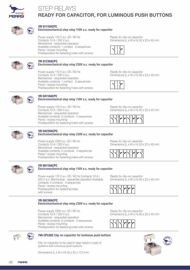
98
1RI 01110ACPCElectromechanical step relay 110V a.c. ready for capacitor
Power supply 110 V a.c. 50 / 60 Hz Contacts 10 A / 250 V a.c. Mechanical - sequential operation Available contacts: 1 contact 2 sequencesPanel / recess mountingPredisposition for fastening holes with screws
Ready for clip-on capacitorDimensions (L x W x H) 35 x 22 x 45 mm
1RI 04110ACPCElectromechanical step relay 110V a.c. ready for capacitor
Power supply 110 V a.c. 50 / 60 Hz Contacts 10 A / 250 V a.c. Mechanical - sequential operation Available contacts: 2 contacts 4 sequencesPanel / recess mountingPredisposition for fastening holes with screws
Ready for clip-on capacitorDimensions (L x W x H) 35 x 22 x 45 mm
1RI 06110ACPCElectromechanical step relay 110V a.c. ready for capacitor
Power supply 110 V a.c. 50 / 60 Hz Contacts 10 A / 250 V a.c. Mechanical - sequential operation Available contacts: 2 contacts 3 sequencesPanel / recess mountingPredisposition for fastening holeswith screws
Ready for clip-on capacitorDimensions (L x W x H) 35 x 22 x 45 mm
1RI 01230ACPCElectromechanical step relay 230V a.c. ready for capacitor
Power supply 110 V a.c. 50 / 60 Hz Contacts 10 A / 250 V a.c. Mechanical - sequential operation Available contacts: 1 contact 2 sequencesPanel / recess mountingPredisposition for fastening holes with screws
Ready for clip-on capacitorDimensions (L x W x H) 35 x 22 x 45 mm
1RI 04230ACPCElectromechanical step relay 230V a.c. ready for capacitor
Power supply 230V a.c. 50 / 60 Hz Contacts 10 A / 250 V a.c. Mechanical - sequential operation Available contacts: 2 contacts 4 sequencesPanel / recess mountingPredisposition for fastening holes with screws
Ready for clip-on capacitorDimensions (L x W x H) 35 x 22 x 45 mm
1RI 06230ACPCElectromechanical step relay 230V a.c. ready for capacitor
Power supply 230V a.c. 50 / 60 Hz Contacts 10 A / 250 V a.c. Mechanical - sequential operation Available contacts: 2 contacts 3 sequencesPanel / recess mountingPredisposition for fastening holes with screws
Ready for clip-on capacitorDimensions (L x W x H) 35 x 22 x 45 mm
1VA CPL002 Clip-on capacitor for luminous push buttons
Clip-on capacitor to be used in step relays in case of systems with luminous push buttons
Dimensions (L x W x H) 35 x 22 x 17.5 mm
STEP RELAYS READY FOR CAPACITOR, FOR LUMINOUS PUSH BUTTONS

99
Power supply 12 V a.c. 50 / 60 Hz Contacts 16 A / 250 V a.c. Mechanical - sequential operation Available contacts: 2 contacts 2 sequencesInstallation on DIN rail
Control buttonDimensions (L x W x H) 17.5 x 60 x 90 mm
Power supply 24 V a.c. 50 / 60 Hz Contacts 16 A / 250 V a.c. Mechanical - sequential operation Available contacts: 2 contacts 2 sequences Installation on DIN rail
Control buttonDimensions (L x W x H) 17.5 x 60 x 90 mm
Power supply 230V a.c. 50 / 60 Hz Contacts 16 A / 250 V a.c. Mechanical - sequential operation Available contacts: 2 contacts 2 sequencesInstallation on DIN rail
Control buttonDimensions (L x W x H) 17.5 x 60 x 90 mm
Power supply 12 V a.c. 50 / 60 Hz Contacts 16 A / 250 V a.c. Mechanical - sequential operation Available contacts: 2 contacts 2 sequencesInstallation on DIN rail
Control buttonDimensions (L x W x H) 17.5 x 60 x 90 mm
Power supply 24 V a.c. 50 / 60 Hz Contacts 16 A / 250 V a.c. Mechanical - sequential operation Available contacts: 2 contacts 2 sequencesInstallation on DIN rail
Control buttonDimensions (L x W x H) 17.5 x 60 x 90 mm
Power supply 230V a.c. 50 / 60 Hz Contacts 16 A / 250 V a.c. Mechanical - sequential operation Available contacts: 2 contacts 2 sequencesInstallation on DIN rail
Control buttonDimensions (L x W x H) 17.5 x 60 x 90 mm
1RI 0412AC/MElectromechanical step relay 12V - 1 DIN
1RI 0424AC/MElectromechanical step relay 24V - 1 DIN
1RI 04230AC/MElectromechanical step relay 230V - 1 DIN
1RI 0212AC/MElectromechanical step relay 12V - 1 DIN
1RI 0224AC/MElectromechanical step relay 24V - 1 DIN
1RI 02230AC/MElectromechanical step relay 230V - 1 DIN
STEP RELAYSDIN RAIL MOUNTING ELECTROMECHANICAL

100
Digital accuracy of preset time - Backlit display - Programming ease
1 - Function search 2 - OK 3 - Time setting 4 - OK
Programming ease with only 4 keys(according to menu logic of mobile phones)
DISPLAY DESCRIPTION
DIGITAL TIME RELAYSDIN MODULAR - 48 X 48
TIME RELAYS - MULTI-VOLTAGE - MULTIFUNCTION - MULTISCALE
• 14 functions available on the display• double adjustment of pause and work times t1 and t2 that can be independently adjusted• digital adjustment of work times in hours - minutes - seconds - tenths of seconds• amber colour backlit display • hour counter of connected load
time scale
hour counter function of the connected load
indication of Operating conditionsdigital adjustment of pause and work times that are finely adjustable for:hour - minutes - seconds and tenths of second
time setting T1 T2selected function
input control condition
1 - Number of the selected function 2 - Timer 1 – Timer 23 - START input status (ON / OFF) 4 - Timer in operation5 - Time set for the timer/hour counter 6 - Hour(s)7 - Minute(s)8 - Second(s)9 - Tenth(s)10- Operating hours multiplier

101
14 AVAILABLE FUNCTIONS - FUNCTION DIAGRAMS
1RT 200/MT/MFMultifunction, multi-voltage timer relay with display - 1 DIN
Power supply 12 - 24 - 48 - 110 - 230V a.c. 50 / 60HzControllable load (in AC1) 16 A / 250 V a.c.Controllable load (in AC15) 3 A / 240V a.c.Potential-free changeover contact14 functions available in the displayDouble timer T1, T2 independently adjustable
Backlit display, amber colourDigital adjustment of work times, hoursminutes seconds and tenths of secondsLoad operation hour counterDimensions (L x W x H) 17.5 x 60 x 90 mm

102
OCTAL / UNDECAL TECHNICAL SPECIFICATIONS
INDUSTRIAL RELAYSOCTAL / UNDECAL SERIES
Main dataType OCTAL / UNDECALPower supply voltage 12 - 24 - 48 - 60V d.c. (mod DC)
12 - 24 - 48 - 110 - 230V a.c. (mod AC)Rated load 10A / 250Va.c. - 30V d.c.Load in AC1 12A / 250Va.c. - 30V d.c.Max commutable power 2500VA / 300WMax commutable voltage 250V a.c. / 30V d.c.Motor power 1/3 HP at 240V a.c. Contact material AG - CdO
DescriptionUse tertiary / industrialType of outputs potential-free changeoverAvailable contacts 2 changeover (2 x ) OCTAL
3 changeover (3 x ) UNDECALDimensions (L x W x H) mm 21,5 x 28 x 36Weight 37 g.
General dataType of installation on a baseProtection degree (IP) IP 20Electrical life (operations) 100.000Mechanical life (operations) 10.000.000Insulation resistance (500 V d.c.) 1.000 MΩDielectric strength (open contacts) 750 V a.c. Dielectric strength (contacts/coil) 3.750 V a.c.Minimum load 100 mA / 5 V d.c.Dissipated power 1.5 W (mod DC)
2.5 VA (mod AC)Operating temperature limits from -55 to + 70 °CIntervention time (with rated voltage) 25 msec maxRelease time (with rated voltage) 25 msec maxRoom temperature -55 ÷ + 70 °CResistance to vibrations 10 ÷ 55 Hz 1.5 mmResistance to collisions (functional) 100 m / sec2 / 10 gResistance to collisions (destructive) 1.000 m / sec2 /100 gHumidity 35 % ÷ 95 %Construction dust-proof coverInsulation rated voltage 250 VWithstand voltage at rated imp. 2,2 KVPollution rating 2Overvoltage category III
Accessoriessee list of accessories

103
Connection diagramsA1 - A2 relay coil
Connection diagramsA1 - A2 relay coil
RELÈ OCTAL
RELÈ UNDECAL
1RE 080212DC OCTAL industrial relay, 12V d.c. Power supply 12V d.c. 2 changeover contacts 10A / 250V
1RE 080224DC OCTAL industrial relay, 24V d.c. Power supply 24V d.c. 2 changeover contacts 10A / 250V
1RE 080248DC OCTAL industrial relay, 48V d.c. Power supply 48V d.c. 2 changeover contacts 10A / 250V
1RE 080260DC OCTAL industrial relay, 60V d.c. Power supply 60V d.c. 2 changeover contacts 10A / 250V
1RE 080212AC OCTAL industrial relay, 12V a.c. Power supply 12V a.c. 2 changeover contacts 10A / 250V
1RE 080224AC OCTAL industrial relay, 24V a.c. Power supply 24V a.c. 2 changeover contacts 10A / 250V
1RE 080248AC OCTAL industrial relay, 48V a.c. Power supply 48V a.c. 2 changeover contacts 10A / 250V
1RE 0802110AC OCTAL industrial relay, 110V a.c. Power supply 110V a.c. 2 changeover contacts 10A / 250V
1RE 0802230AC OCTAL industrial relay, 230V a.c. Power supply 230V a.c. 2 changeover contacts 10A / 250V
1RE 110312DC UNDECAL industrial relay, 12V d.c. Power supply 12V d.c. 3 changeover contacts 10A / 250V
1RE 110324DC UNDECAL industrial relay, 24V d.c. Power supply 24V d.c. 3 changeover contacts 10A / 250V
1RE 110348DC UNDECAL industrial relay, 48V d.c. Power supply 48V d.c. 3 changeover contacts 10A / 250V
1RE 110360DC UNDECAL industrial relay, 60V d.c. Power supply 60V d.c. 3 changeover contacts 10A / 250V
1RE 110312AC UNDECAL industrial relay, 12V a.c. Power supply 12V a.c. 3 changeover contacts 10A / 250V
1RE 110324AC UNDECAL industrial relay, 24V a.c. Power supply 24V a.c. 3 changeover contacts 10A / 250V
1RE 110348AC UNDECAL industrial relay, 48V a.c. Power supply 48V a.c. 3 changeover contacts 10A / 250V
1RE 1103110AC UNDERCAL industrial relay, 110V a.c. Power supply 110V a.c. 3 changeover contacts 10A / 250V
1RE 1103230AC UNDECAL industrial relay, 230V a.c. Power supply 230V a.c. 3 changeover contacts 10A / 250V

104
1RE EK 8 OCTAL socket, screw terminals
1RE ES 8 OCTAL socket, clamp teminals
1RE ES 9 OCTAL socket, clamp terminals with predisposition for protection modules
OCTAL / UNDECAL BASES
Protection degree IP 20 Electrical connection with quick couplingOperating Temp. - 40 ÷ 85 oC
WIRING AUXILIARY DEVICES
1RE T Writable plate for ES8 - ES11 for OCTAL - UNDECAL socket (thermoplastic material)30
6
1RE MH 1 Relay fastening spring for OCTAL - UNDECAL relays (metallic material)
PROTECTION MODULES
1RE 11 Module with polarized diode –A1 +A2
for d.c. protection against overvoltage from open coil 6-230V d..
1RE 21 Module with polarized diode +A1 -A2
for d.c. protection against overvoltage from open coil 6-230V d.c.
1RE 51B Module with RC
for a.c. protection against overvoltage from open coil 6-24V a.c.
1RE 51D Module with RC
for a.c. protection against overvoltage from open coil 24-60V a.c.
1RE 51C Module with RC
1RE 71 Module with varistor
1RE 71A Module with RC
1RE 81 Module with RC
for a.c. protection against overvoltage from open coil 110-230V a.c.
for protection against external overvoltage 24V a.c.
for protection against external overvoltage 115V a.c.
for protection against external overvoltage 230V a.c.
Protection degree IP 20 Electrical connection 1 ÷ 2,5 mm2
Operating Temp. - 40 ÷ 85 °CWall-mounted or installed on DIN rail
1RE EK 11 UNDECAL socket, screw terminals
1RE ES 11 UNDECAL socket, clamp teminals
1RE ES 12 UNDECAL socket, clamp terminals with predisposition for protection modules
INDUSTRIAL RELAYSOCTAL / UNDECAL SERIES ACCESSORIES

105
INDUSTRIAL RELAYSMIDI SERIES, 2 - 4 CONTACTS
MIDI 2
MIDI 4
TECHNICAL SPECIFICATIONS
MIDI 4
Main dataType MIDI-2 Power supply voltage 12 - 24 - 48 - 60V d.c. (mod DC)
12 - 24 - 48 - 110 - 230V a.c. (mod AC)Rated load 10A / 250Va.c. - 30V d.c. (MIDI-2)
5A / 250Va.c. - 30V d.c. (MIDI-4)Load in AC1 12A / 250Va.c. - 30V d.c. (MIDI-2)
6A / 250Va.c. - 30V d.c. (MIDI-4)Max commutable power 2500VA / 300W (MIDI-2)
1250VA / 300W (MIDI-4)Max commutable voltage 250V a.c. / 30V d.c.Motor power 1/3 HP a 240V a.c. (MIDI-2)
1/6 HP a 240V a.c. (MIDI-4)Contact material AG - CdO Type of Operation monostable
DescriptionUse tertiary / industrialType of outputs potential-free changeoverAvailable contacts 2 changeover (2 x ) (MIDI-2)
4 changeover (3 x ) (MIDI- 4)Dimensions (L x W x H) mm 21,5 x 28 x 36Weight 37 g.
General dataType of installation on socketProtection degree (IP) IP 20Electrical life (operations) 100.000Mechanical life (operations) 10.000.000Insulation resistance (500 V d.c.) 1.000 MΩDielectric strength (open contacts) 750 V a.c. (MIDI-2)
1.550V a.c. (MIDI-4)Dielectric strength (contacts/coil) 3.750 V a.c.Minimum load 100 mA / 5 V d.c.Dissipated power 0.9 W (mod DC)
1.2 VA (mod AC)Operating temperature limits from -55°C to +70°CIntervention time (with rated voltage) 25 msec maxRelease time (with rated voltage) 25 msec maxRoom temperature -55 ÷ + 70 °CResistance to vibrations 10 ÷ 55 Hz 1.5 mmResistance to collisions (functional) 100 m / sec2 /10 gResistance to collisions (destructive) 1.000 m / sec2 /100 gHumidity 35 % ÷ 95 %Construction dust-proof coverInsulation rated voltage 250 VWithstand voltage at rated imp. 2,2 KVPollution rating 2Overvoltage category III
Accessoriessee list of accessories

106
INDUSTRIAL RELAYSMIDI SERIES, 2 - 4 CONTACTS
Connection diagramsA1 - A2 relay coil
Connection diagramsA1 - A2 relay coil
MIDI SERIES RELAYS, 2 CONTACTS
MIDI SERIES RELAYS, 4 CONTACTS
1RE 021012DC MIDI industrial relay, 2 contacts 12V d.c. Power supply 12V d.c. 2 changeover contacts 10A / 250V
1RE 021024DC MIDI industrial relay, 2 contacts 24V d.c. Power supply 24V d.c. 2 changeover contacts 10A / 250V
1RE 021048DC MIDI industrial relay, 2 contacts 48V d.c. Power supply 48V d.c. 2 changeover contacts 10A / 250V
1RE 021012AC MIDI industrial relay, 2 contacts 12V a.c. Power supply 12V a.c. 2 changeover contacts 10A / 250V
1RE 021024AC MIDI industrial relay, 2 contacts 24V a.c. Power supply 24V a.c. 2 changeover contacts 10A / 250V
1RE 021048AC MIDI industrial relay, 2 contacts 48V a.c. Power supply 48V a.c. 2 changeover contacts 10A / 250V
1RE 0210110AC MIDI industrial relay, 2 contacts 110V a.c. Power supply 110V a.c. 2 changeover contacts 10A / 250V
1RE 0210230AC MIDI industrial relay, 2 contacts 230V a.c. Power supply 230V a.c. 2 changeover contacts 10A / 250V
1RE 040512DC MIDI industrial relay, 4 contacts 12V d.c. Power supply 12V d.c. 4 changeover contacts 10A / 250V
1RE 040524DC MIDI industrial relay, 4 contacts 24V d.c. Power supply 24V d.c. 4 changeover contacts 10A / 250V
1RE 040548DC MIDI industrial relay, 4 contacts 48V d.c. Power supply 48V d.c. 4 changeover contacts 10A / 250V
1RE 040512AC MIDI industrial relay, 4 contacts 12V a.c. Power supply 12V a.c. 4 changeover contacts 10A / 250V
1RE 040524AC MIDI industrial relay, 4 contacts 24V a.c. Power supply 24V a.c. 4 changeover contacts 10A / 250V
1RE 040548AC MIDI industrial relay, 4 contacts 48V a.c. Power supply 48V a.c. 4 changeover contacts 10A / 250V
1RE 0405110AC MIDI industrial relay, 4 contacts 110V a.c. Power supply 110V a.c. 4 changeover contacts 10A / 250V
1RE 0405230AC MIDI industrial relay, 4 contacts 230V a.c. Power supply 230V a.c. 4 changeover contacts 10A / 250V

107
Protection degree IP 20 Electrical connection 1 ÷ 2,5 mm2
Operating Temp. - 25 ÷ 85 °C
Wall-mounted or installed on DIN railPresetting for protection modules
1RE ES 15 /2B Socket with screw terminals for 2-changeover relay
1RE ES 15 /2N Socket with clamp terminals for 2-changeover relay
1RE ES 15 /2S Socket with clamp terminals for 2-changeover relay
1RE ES 15 /3N Socket with clamp terminals for 3-changeover relay
1RE ES 15 /3S Socket with clamp terminals for 3-changeover relay
1RE ES 15 /4B Socket with screw terminals for 4-changeover relay
1RE ES 15 /4N Socket with clamp terminals for 4-changeover relay
1RE ES 15 /4S Socket with clamp terminals for 4-changeover relay
MIDI SICKETS, 2 - 4 CONTACTS
WIRING AUXILIARY ACCESSORIES1RE TR1 Plate for sockets type ES15/2B-4B-2N-3N-4N-2S-3S-4S (thermoplastic material)
156
1RE MH0 Fastening spring for MIDI relays on sockets type ES15/2B-4B-2N-3N-4N-2S-3S-4S (metallic material)
1RE MS35 Disconnection and fastening spring for MIDI relays on sockets type ES15/2N-3N-4N-2S-3S-4S (thermoplastic material)
Protection degree IP 20 Electrical connection with quick couplingOperating Temp. - 25 ÷ 85 °C
PROTECTION MODULES
1RE 12 Module with polarized diode –A1 +A2
for d.c. protection against overvoltage from open coil 6-230V d.c.
1RE 22 Module with polarized diode –A1 +A2
for d.c. protection against overvoltage from open coil 6-230V d.c.
1RE 52B Module with RC
for a.c. protection against overvoltage from open coil 6-24V a.c.
1RE 52D Module with RC
for a.c. protection against overvoltage from open coil 24-60V a.c.
1RE 52C Module with RC
1RE 72 Module with varistor
1RE 72A Module with RC
1RE 82 Module with RC
for a.c. protection against overvoltage from open coil 110-230V a.c.
for protection against external overvoltage 24V a.c.
for protection against external overvoltage 115V a.c.
for protection against external overvoltage 230V a.c.

108
MEASURING INSTRUMENTS, CURRENT TRANSFORMERSHOUR-COUNTERS
SD02AV/2 - SD03A/2 - SD04V/2
TA00/10TA00/25TA00/40
2400 - 1100 - 2200 - 3800 - CC1236 CO24/2 - CO110/2 - CO230/2 CO36C/2
TA02/50TA02/60TA02/100
TA03/40TA03/50TA03/60TA03/100
TA04/150TA04/200TA04/250
TA05/400TA05/500TA05/600
TA06/800TA06/1000
SD05MM/2 SD10MT/2
MEASURING INSTRUMENTS
CURRENT TRANSFORMERS
HOUR-COUNTERS
AMMETERS VOLTMETERS
WOUND PRIMARY
PANEL MOUNTING
SINGLE-PHASE MULTIMETERS
THROUGH PRIMARY
DIN RAIL MOUNTING
THREE-PHASE MULTIMETERS
CE MARKING STANDARDS
LVD: 2006/95/CE EN 61010-1, EN 60688EMC: 2004/108/CE EN 61000-6-2, EN 61000-6-4, EN 55011
CE MARKING STANDARDS
LVD: 2006/95/CE EN 61010-1EMC: 2004/108/CE EN 61000-6-2, EN 61000-6-4
CE MARKING STANDARDS
LVD: 2006/95/CE EN 60044-1

109
SD05CEM/2 - SD06CEM/1 SD07CET/4 - SD08CET/4SD09CET/4
SD11CCE/4 SD31AR/4
SINGLE-PHASE ENERGY COUNTER
THREE-PHASE ENERGY COUNTER
PULSE CONCENTRATOR NETWORK ANALYSERTHREE-PHASE MULTIMETERS
CE MARKING STANDARDS
LVD: 2006/95/CE EN 62053-21, EN 50470-1, EN 50470-3EMC: 2004/108/CE EN 61000-6-2, EN 61000-6-4, EN 55011

110
Digital modular voltmeter and ammeter for alternate current measurements with 3-digit LED display Power supply 230V a.c. +-10% 50-60HzInput current 5A a.c.CAT III 300V
Amperometric loads between 5 and 999 A with TAReading accuracy class 0.5%Dimensions (L x W x H) 35 x 63 x 85 mm
It records the consumption of ACTIVE energy in single-phase 230V systems, up to a maximum current of 30A with one open-collector 100ms impulsive output every 10W consumedPower supply 230V a.c. +-10% 50-60HzReading resolution 0.01 kWh
Accuracy Class ANumber of digits: 5 integers + 2 decimalsRated voltage 230VRated current 5A (30A max)EN50470-1, EN50470-3 and EN62059-41 standardsDimensions (L x W x H) 17.5 x 64.4 x 90 mm
Digital modular ammeter for alternate current measurements with 3-digit LED displayPower supply 230V a.c. +-10% 50-60HzInput current Inom= 5A Imax= 6A a.c.
CAT III 300V Amperometric loads between 5 and 999 A with TA Reading accuracy class 0.5% Dimensions (L x W x H) 35 x 63 x 85 mm
Digital modular voltmeter for alternatecurrent measurements with 3-digit LED displayPower supply 230V a.c. +-10% 50-60HzInput voltage 0..500V max a.c. (45…100Hz) input impedance=1.5Mohm
CAT III 300VAmperometric loads between 5 and 999 A with TAReading accuracy class 0.5%Dimensions (L x W x H) 35 x 63 x 85 mm
Digital single-phase multimeter with 3-digit LED display on 2 linesVoltage measurement 0-230VCurrent measurement 0.1-26A (30A)Active Power Measurement 8.00kWActive Energy Measurement (Wh) on 2 lines
Accounting period 15 minDirect connection energy count 9.99 / 999 kWhMeasurement of the power factorHour counterDigital filterDimensions (L x W x H) 35 x 63 x 85 mm
Digital three-phase multimeter with3-digit LED display on 2 linesPhase-phase voltage VL1, VL2, VL3Phase-neutral voltage VL1-N, VL2-N, VL3-NAverage VL phase average voltage
Phase current I1, I2, I3Phase average current I averageCurrent in “len” neutral (<imbalance>)Basic active powerDimensions (L x W x H) 35 x 63 x 85 mm
It records the consumption of ACTIVE energy in single-phase 230V systems, up to a maximum current of 30A with one open-collector 100ms impulsive output every 10W consumedPower supply 230V a.c. +-10% 50-60HzReading resolution 0.01 kWh
Accuracy Class ANumber of digits: 5 integers + 2 decimalsRated voltage 230VRated current 5A (30A max)EN50470-1, EN50470-3 and EN62059-41 standardsDimensions (L x W x H) 35 x 63 x 85 mm
1SD SD02AV/2Ammeter and voltmeter for alternate current measurements - 2 DIN
1SD SD06CEM/1Single-phase energy counter - 1 DIN
1SD SD03A/2Ammeter for alternate current measurements - 2 DIN
1SD SD04V/2Voltmeter for alternate current measurements - 2 DIN
1SD SD05MM/2Single-phase multimeter - 2 DIN
1SD SD10MT/2Three-phase multimeter - 2 DIN
1SD SD05CEM/2Single-phase energy counter - 2 DIN
MEASURING INSTRUMENTS

111
1SD SD09CET/4Three-phase energy counter 63A - 4 DIN
It records the consumption of ACTIVE energy in three-phase 400V systems, up to the maximum current of 63A with one open-collector 100ms impulsive output every 100W consumedPower supply 400 V +-10% 50-60Hz Reading resolution 0.01 kWh Accuracy Class A
Number of digits: 6 integers + 1 decimalConnection in TA (4 wires with neutral)Rated voltage 3x230 / 400VRated current 63AEN50470-1, EN50470-3 and EN62059-41 standardsDimensions (L x W x H) 70 x 63 x 85 mm
1SD SD08CET/4Three-phase energy counter 30A - 4 DIN
It records the consumption of ACTIVE energy in three-phase 400V systems, up to the maximum current of 32A with one open-collector 100ms impulsive output every 100W consumedPower supply 400 V +-10% 50-60Hz Reading resolution 0.01 kWh Accuracy Class A
Number of digits: 6 integers + 1 decimalConnection in TA (4 wires with neutral)Rated voltage 3x230 / 400VRated current 32AEN50470-1, EN50470-3 and EN62059-41 standardsDimensions (L x W x H) 70 x 63 x 85 mm
1SD SD07CET/4Three-phase energy counter 5/TA - 4 DIN
It records the consumption of ACTIVE energy in three-phase 400V a.c. systems with neutral, with connection TA…/5° and the possibility to program the ratio, one programmable impulsive output, through a reed relay for the remote signalling of consumptionsup to a maximum 30A current with one open-collector 100ms impulsive output every 10W consumedPower supply 400 V +-10% auto-fed 50-60Hz
Reading resolution 0.01 kWhAccuracy Class ANumber of digits: 6 integers + 1 decimalConnection in TA (4 wires with neutral)Rated voltage 3x230 / 400VRated current 5A (30A max)EN50470-1, EN50470-3 and EN62059-41 standardsDimensions (L x W x H) 70 x 63 x 85 mm
1SD SD11CCE/4Pulse concentrator, energy counter - 3 DIN
Power supply 230V +/- 10% 50 / 60Hz Inputs 5 with NO or NC free contact (programmable from software)MODBUS RTU protocol input
Management softwareDimensions (L x W x H) 52.5 x 58 x 85 mm
Collects the impulses from energy counters (max 5), totals them, and puts them at disposal for a Master MODBUS.
1SD SD31AR/4Network analyser - 4 DIN
Power supply 110V, 230V, 400V 50 / 60HzVoltmeter inputAmperometric inputMeasurement: voltage, current, active power, reactive power, apparent power, active energy, reactive energy
16-digit white LED displayProgrammable threshold alarm contactDimensions (L x W x H) 70 x 58 x 85 mm
It displays three-phase electrical measures for voltage, current, power, energy, frequency, hour counter. Equipped with back-lighting, alarm relay, set-point memory and energy.

112
CURRENT TRANSFORMERS
1TA TA00/25Wound primary current transformer 25/5 A
Accuracy class 0.5Power 6VA
Installation on DIN rail and / or wall-mountedDimensions (L x W x H) 75 x 44 x 109 mm
1TA TA03/50Through primary current transformer 50/5 A
Accuracy class 3Power 3A
Installation on DIN rail and / or wall-mountedDimensions (L x W x H) 58 x 44 x 97 mm
1TA TA03/60Through primary current transformer 60/5 A
Accuracy class 3Power 3A
Installation on DIN rail and / or wall-mountedDimensions (L x W x H) 58 x 44 mm
1TA TA03/100Through primary current transformer 100/5 A
Accuracy class 1Power 3A
Installation on DIN rail and / or wall-mountedDimensions (L x W x H) 58 x 44 x 97 mm
1TA TA02/60Wound primary current transformer 60/5 A
Accuracy class 0.5Power 6VA
Installation on DIN rail and / or wall-mountedDimensions (L x W x H) 75 x 44 x 109 mm
1TA TA02/100Wound primary current transformer 100/5 A
Accuracy class 0.5Power 6VA
Installation on DIN rail and / or wall-mountedDimensions (L x W x H) 75 x 44 x 109 mm
1TA TA00/40Wound primary current transformer 40/5 A
Accuracy class 0.5Power 6VA
Installation on DIN rail and / or wall-mountedDimensions (L x W x H) 75 x 44 x 109 mm
1TA TA00/10Wound primary current transformer 10/5 A
Accuracy class 0.5Power 6VA
Installation on DIN rail and / or wall-mountedDimensions (L x W x H) 75 x 44 x 109 mm
1TA TA02/50Wound primary current transformer 50/5A
Accuracy class 0.5Power 6VA
Installation on DIN rail and / or wall-mountedDimensions (L x W x H) 75 x 44 x 109 mm
1TA TA03/40Through primary current transformer 40/5 A
Accuracy class 3Power 2VA
Installation on DIN rail and / or wall-mountedDimensions (L x W x H) 58 x 44 x 97 mm

113
1TA TA04/200Through primary current transformer 200/5 A
Accuracy class 0.5Power 3A
Installation on DIN rail and / or wall-mountedDimensions (L x W x H) 58 x 44 mm
1TA TA04/250Through primary current transformer 250/5 A
Accuracy class 0.5Power 5A
Installation on DIN rail and / or wall-mountedDimensions (L x W x H) 58 x 44 x 97 mm
1TA TA05/500Through primary current transformer 500/5 A
Accuracy class 0.5Power 10A
Installation on DIN rail and / or wall-mountedDimensions (L x W x H) 75 x 44 x 109 mm
1TA TA05/600Through primary current transformer 600/5 A
Accuracy class 0.5Power 10A
Installation on DIN rail and / or wall-mountedDimensions (L x W x H) 75 x 44 x 109 mm
1TA TA06/800Through primary current transformer 800/5 A
Accuracy class 0.5Power 10A
Installation on DIN rail and / or wall-mountedDimensions (L x W x H) 105 x 61 x 131 mm
1TA TA06/1000Through primary current transformer 1000/5 A
Accuracy class 0.5Power 10A
Installation on DIN rail and / or wall-mountedDimensions (L x W x H) 105 x 61 x 131 mm
1TA TA05/400Through primary current transformer 400/5 A
Accuracy class 0.5Power 10A
Installation on DIN rail and / or wall-mountedDimensions (L x W x H) 75 x 44 x 109 mm
1TA TA04/150Through primary current transformer 150/5 A
Accuracy class 0.5Power 3A
Installation on DIN rail and / or wall-mountedDimensions (L x W x H) 58 x 44 x 97 mm

114
1CO 2400Hour counter 24 V a.c.
Power supply 24V a.c. 50HzRecording ability 99,999.99
Installed in the panel / on rear of switchboardDimensions (L x W x H) 55 x 56 x 55 mm
1CO 1100Hour counter 110 V a.c.
Power supply 110V a.c. 50HzRecording ability 99,999.99
Installed in the panel / on rear of switchboardDimensions (L x W x H) 55 x 56 x 55 mm
1CO 2200Hour counter 220 V a.c.
Power supply 220V a.c. 50HzRecording ability 99,999.99
Installed in the panel / on rear of switchboardDimensions (L x W x H) 55 x 56 x 55 mm
1CO 3800Hour counter 380 V a.c.
Power supply 380V a.c. 50HzRecording ability 99,999.99
Installed in the panel / on rear of switchboardDimensions (L x W x H) 55 x 56 x 55 mm
1CO CC1236Hour counter 12-36 V d.c.
Power supply 12-36V d.c. Recording ability 99,999.99
Installed in the panel / on rear of switchboardDimensions (L x W x H) 55 x 56 x 55 mm
HOUR-COUNTERS

115
1CO CO24/2Hour counter 24 V - 2 DIN
Power supply 24V a.c. 50Hz <10VA Recording ability 99,999.99Accuracy class 0.5%
Reading accuraacy 1/100h (36sec)2 DIN moduleDimensions (L x W x H) 35 x 63 x 85 mm
1CO CO110/2 Hour counter 110V - 2 DIN
Power supply 110V a.c. 50Hz <10VA Recording ability 99,999.99Accuracy class 0.5%
Reading accuracy 1/100h (36sec)2 DIN moduleDimensions (L x W x H) 35 x 63 x 85 mm
1CO CO230/2Hour counter 230V - 2 DIN
Power supply 230V a.c. 50Hz <10VA Recording ability 99,999.99Accuracy class 0.5%
Reading accuracy 1/100h (36sec)2 DIN moduleDimensions (L x W x H) 35 x 63 x 85 mm
1CO CO36C/2Hour counter 12-36 V d.c. - 2 DIN
Power supply 12-36V d.c. < 10VA Recording ability 99,999.99Accuracy class 1%
Reading accuracy 1/10h (6min)2 DIN moduleDimensions (L x W x H) 35 x 63 x 85 mm
HOUR-COUNTERSDIN RAIL MOUNTING

116
The essential feature of the “30” series is a heavy body but compact, without harshness which makes it ideal for use with sewage and with industrial water, both in filling and in emptying.Consisting of a housing with inside a float switch and counter weight so that a level increase will generate a reversal of the position of the regulator itself.The high-pressure body in molten polypropylene ensures a perfect seal to infiltration.The small size and reduced switching angle allow the use in narrow wells.
The level regulator for clear water is a floating switch for the management of liquid level. It allows connecting electrical appliances (usually pumps, but also solenoid valves, alarms, motor driven shutters, etc.) when reaching a preset level. Made with non-toxic polypropylene: it can be used also in contact with food liquids.
They are regulators for conductive liquids, suitable to control minimum and maximum levels of deep wells, reservoirs, tanks, etc. The Operating principle is based on the detection, by the control unit, of liquid resistance, whose level is controlled by means of specific probes being installed in the same device; the longest probe is used as common item. When the level of the liquid inside the container or the well soaks the three submerged probes (common, low, high), the relay will be activated. The same relay will be deactivated only when the level lowers and uncovers the low probe.
RLG01/3PVC - RLG02/5PVCRLG03/10PVC - RLG04/15PVCRLG05/20PVC - RLG06/25PVCRLG025NEOP - RLG0310NEOPRLG0520NEOP
RLE024/2 - RLE230/2 RLEME/3 - RLE230E/2
LEVEL REGULATORS ELECTROMECHANICAL
LEVEL REGULATORS ELECTRONIC
CLEAR WATER
SEWAGE WATER “30 SERIES”
ELETTRONIC ELECTRONIC E SERIES (EVOLVED)
CE MARKING STANDARDS
LVD: 2006/95/CE EN 60730-1, EN 60730-2-16
CE MARKING STANDARDS
LVD: 2006/95/CE EN 60730-1EMC: 2004/108/CE EN 55014-1, EN 55014-2, EN 61000-3-2, EN 61000-3-3
LEVEL REGULATORS
RLG3005PVC - RLG3010PVC RLG3020PVCRLG3005NEOP - RLG3010NEOP RLG3020NEOP

117
RLG10/5PVC - RLG11/10PVCRLG12/20PVC RLG20/5NEOP - RLG21/10NEOPRLG22/20NEOP
SF010 ST021
It’s a tilting submerged level regulator. Its crucial feature is that it has a heavy and voluminous body, free from unevenness, which enhances its use in sewer water, industrial water with suspended agglomerate residues and turbulent water. This regulator includes a case, inside of which there is a floating switch that is counterbalanced, so that when the level increases, the position of the regulator will reverse. While the level is reducing, the regulator will tilt in the opposite direction. The high-pressure cast polypropylene body assures a perfect sealing against seepages.
ACCESSORIES
SEWAGE WATER

118
FILLING
M
BLUE
BLACK
BROWNL
N
InstallationInstallationEMPTYING
M
BLUE
BLACK
BROWN L
N
1CL RLG02/5PVCFloating level regulator for clear water, PVC cable 3x1, 5m longElectric range 10 (8) A / 250 V Operating Temperature 0-50°CPressure resistance 1 BAR
Protection degree IP 68Dimensioni (L x W x H) 81 x 131 x 42 mm
1CL RLG03/10PVCFloating level regulator for clear water, PVC cable 3x1, 10m long Electric range 10 (8) A / 250 V Operating Temperature 0-50°CPressure resistance 1 BAR
Protection degree IP 68Dimensioni (L x W x H) 81 x 131 x 42 mm
1CL RLG04/15PVCFloating level regulator for clear water, PVC cable 3x1, 15m longElectric range 10 (8) A / 250 V Operating Temperature 0-50°CPressure resistance 1 BAR
Protection degree IP 68Dimensioni (L x W x H) 81 x 131 x 42 mm
1CL RLG05/20PVCFloating level regulator for clear water, PVC cable 3x1, 20m longElectric range 10 (8) A / 250 V Operating Temperature 0-50°CPressure resistance 1 BAR
Protection degree IP 68Dimensioni (L x W x H) 81 x 131 x 42 mm
1CL RLG06/25PVCFloating level regulator for clear water, PVC cable 3x1, 25m longElectric range 10 (8) A / 250 V Operating Temperature 0-50°CPressure resistance 1 BAR
Protection degree IP 68Dimensioni (L x W x H) 81 x 131 x 42 mm
Electric range 10 (8) A / 250 VOperating Temperature 0-50°CPressure resistance 1 BAR
Protection degree IP 68Dimensioni (L x W x H) 81 x 131 x 42 mm
1CL RLG01/3PVCFloating level regulator for clear water, PVC cable 3x1, 3m long
1CL RLG0310NEOPFloating level regulator for clear water, neoprene cable 3x1, 10m long Electric range 10 (8) A / 250 V Operating Temperature 0-50°CPressure resistance 1 BAR
Protection degree IP 68Dimensioni (L x W x H) 81 x 131 x 42 mm
1CL RLG0520NEOPFloating level regulator for clear water, neoprene cable 3x1, 20m long Electric range 10 (8) A / 250 V Operating Temperature 0-50°CPressure resistance 1 BAR
Protection degree IP 68Dimensioni (L x W x H) 81 x 131 x 42 mm
Electric range 10 (8) A / 250 VOperating Temperature 0-50°CPressure resistance 1 BAR
Protection degree IP 68Dimensioni (L x W x H) 81 x 131 x 42 mm
1CL RLG025NEOPFloating level regulator for clear water, neoprene cable 3x1, 5m long
LEVEL REGULATORS FOR CLEAR WATER

119
LEVEL REGULATORS FOR SEWAGE WATER
1CL RLG20/5NEOPFloating level regulator for sewage water, neoprene cable 3x1, 5m long
Electric range 10 (8) A / 250 V Switching angle ±45°Operating Temperature 0-50°C
Pressure resistance 2 BARProtection degree IP 68Dimensioni (L x W x H) 117 x 117 x 222 mm
1CL RLG11/10PVCFloating level regulator for sewage water, PVC cable 3x1, 10m long
Electric range 10 (8) A / 250 V Switching angle ±45°Operating Temperature 0-50°C
Pressure resistance 2 BARProtection degree IP 68Dimensioni (L x W x H) 117 x 117 x 222 mm
1CL RLG21/10NEOPFloating level regulator for sewage water, neoprene cable 3x1, 10m long
Electric range 10 (8) A / 250 V Switching angle ±45°Operating Temperature 0-50°C
Pressure resistance 2 BARProtection degree IP 68Dimensioni (L x W x H) 117 x 117 x 222 mm
1CL RLG12/20PVCFloating level regulator for sewage water, PVC cable 3x1, 20m long
Electric range 10 (8) A / 250 V Switching angle ±45°Operating Temperature 0-50°C
Pressure resistance 2 BARProtection degree IP 68Dimensioni (L x W x H) 117 x 117 x 222 mm
1CL RLG22/20NEOPFloating level regulator for sewage water, neoprene cable 3x1, 20m long
Electric range 10 (8) A / 250 V Switching angle ±45°Operating Temperature 0-50°C
Pressure resistance 2 BARProtection degree IP 68Dimensioni (L x W x H) 117 x 117 x 222 mm
1CL RLG10/5PVCFloating level regulator for sewage water, PVC cable 3x1, 5m long
Electric range 10 (8) A / 250 V Switching angle ±45°Operating Temperature 0-50°C
Pressure resistance 2 BARProtection degree IP 68Dimensioni (L x W x H) 117 x 117 x 222 mm
M M
FILLING EMPTYING
BLUE
BLUE BLUE
BLACK BLACK
BROWN BROWN
BROWN
CAUTIONThe unused cable must be properly
isolated (brown for filling blue for emptying)
T
RS
TN
RS
N
3x1 CABLEThe cable BLUE / BLACK
closes the contact with the float in down position andopens in upwards position.The BROWN / BLACK cable closes the contact with the float in upwards position and opens in downwards
position.
S T A R T
S T OP S T A R T
S T OP

120
LEVEL REGULATORS FOR SEWAGE WATER“30 SERIES”
1CL RLG3005NEOPFloating level regulator for sewage water, neoprene cable 3x1, 5m long
Electric range 10 (3) A / 250 V (ENEC approved)Switching angle ±10°Operating Temperature 0-50°CPressure resistance 2 BAR
Protection degree IP 68ENEC approvedDimensions (L x W x H) 100 x 100 x 156 mm
1CL RLG3010PVCFloating level regulator for sewage water, PVC cable 3x1, 10m long
Electric range 10 (3) A / 250 VSwitching angle ±10°Operating Temperature 0-50°C
Pressure resistance 2 BARProtection degree IP 68Dimensions (L x W x H) 100 x 100 x 156 mm
1CL RLG3010NEOPFloating level regulator for sewage water, neoprene cable 3x1, 10m long
Electric range 10 (3) A / 250 V (ENEC approved)Switching angle ±10°Operating Temperature 0-50°CPressure resistance 2 BAR
Protection degree IP 68ENEC approvedDimensions (L x W x H) 100 x 100 x 156 mm
1CL RLG3020PVCFloating level regulator for sewage water, PVC cable 3x1, 20m long
Electric range 10 (3) A / 250 VSwitching angle ±10°Operating Temperature 0-50°C
Pressure resistance 2 BARProtection degree IP 68Dimensions (L x W x H) 100 x 100 x 156 mm
1CL RLG3020NEOPFloating level regulator for sewage water, neoprene cable 3x1, 20m long
Electric range 10 (3) A / 250 V (ENEC approved)Switching angle ±10°Operating Temperature 0-50°CPressure resistance 2 BAR
Protection degree IP 68ENEC approvedDimensions (L x W x H) 100 x 100 x 156 mm
1CL RLG3005PVCFloating level regulator for sewage water, PVC cable 3x1, 5m long
Electric range 10 (3) A / 250 VSwitching angle ±10°Operating Temperature 0-50°C
Pressure resistance 2 BARProtection degree IP 68Dimensions (L x W x H) 100 x 100 x 156 mm
M M
FILLING EMPTYING
BLUE
BLUE BLUE
BLACK BLACK
BROWN BROWN
BROWN
CAUTIONThe unused cable must be properly
isolated (brown for filling blue for emptying)
T
RS
TN
RS
N
3x1 CABLEThe cable BLUE / BLACK
closes the contact with the float in down position andopens in upwards position.The BROWN / BLACK cable closes the contact with the float in upwards position and opens in downwards
position.
S T A R T
S T OP S T A R T
S T OP

121
Power supply 24/117/230V 50-60 HzElectrode voltage 12VppRange of 1st relay 5A / 250 VRange of 2nd relay 2A / 250 VAdjustable intervention delay 0 - 16secEmptying / filling intervention modeMax. connection length betweencontrol unit and probes, approx. 1000mInstallation on terminal board IP 20Installation on rear of switchboard IP 40Dimensions (L x W x H) 53 x 58 x 95 mm
1CL RLEME/3Multivoltage electronic level regulator series E evolved - 3 DIN
Power supply 230V 50-60 HzElectrode voltage 12VppRelay range 5A / 250 VAdjustable intervention delay 0 - 16secEmptying / filling intervention modeMax. connection length betweencontrol unit and probes, approx. 1000mInstallation on terminal board IP 20Installation on rear of switchboard IP 40Dimensions (L x W x H) 37 x 58 x 95 mm
1CL RLE230E/2Electronic level regulator 230V series E evolved - 2 DIN
ACCESSORIES1CL SF010 Probe with electronic wire connection Installation directly in the liquidMax. operating temperatures 80°C
Dimensions (D x L) 22 x 85 mm
1CL ST021 3-conductor probe holder
Installation hole D 65mm Max. operating temperatures 80°C
Dimensions (D x L) 80 x 72 mm
Power supply 24V 50-60 HzElectrode voltage 12VRelay range 5A / 250 VAdjustable sensitivityMax. connection length betweencontrol unit and probes, approx. 70-80mInstallation on terminal board IP 20Installation on rear of switchboard IP 40Dimensions (L x W x H) 37 x 58 x 95 mm
1CL RLE024/2Electronic level regulator 24V - 2 DIN
Power supply 230V 50-60 HzElectrode voltage 12VRelay range 5A / 250 VAdjustable sensitivityMax. connection length betweencontrol unit and probes, approx. 70-80mInstallation on terminal board IP 20Installation on rear of switchboard IP 40Dimensions (L x W x H) 37 x 58 x 95 mm
1CL RLE230/2Electronic level regulator 230V - 2 DIN
12 11 10 9 8 7
1 2 3 4 5 6C B A
S1S2
S3
C N CNA
1CL RLE230E/21CL RLEME/3
18 17 16 15 14 13
1 2 3 4 5 6
CBA
NC1 C1NA1
S1
S2
S3
7 8 9
12 11 10
230V c.a.117V c.a.
24V c.a.0V c .a.
NC CNA
12 11 10 9 8 7
1 2 3 4 5 6C B A
S1S2
S3
C N CNA
1CL RLE230E/21CL RLEME/3
18 17 16 15 14 13
1 2 3 4 5 6
CBA
NC1 C1NA1
S1
S2
S3
7 8 9
12 11 10
230V c.a.117V c.a.
24V c.a.0V c .a.
NC CNA
12 11 10 9 8 7
1 2 3 4 5 6C B A
S1S2
S3
C N CNA
1CL RLE024/2
12 11 10 9 8 7
1 2 3 4 5 6C B A
S1S2
S3
C N CNA
1CL RLE230/2
12 11 10 9 8 7
1 2 3 4 5 6C B A
S1S2
S3
C N CNA
1CL RLE024/2
12 11 10 9 8 7
1 2 3 4 5 6C B A
S1S2
S3
C N CNA
1CL RLE230/2
24V a.c. 50-60 Hz
24V a.c. 50-60 Hz
24V a.c. 50-60 Hz
230V a.c.117V a.c.24V a.c.0V a.c.

122
HYGIENE DEVICES
ASE03 AMP03 - AMF04ASM01N - ASE02N
DS008 DC009
HYGIENE DEVICESHAND DRYERS
LIQUID SOAP DISPENSER PAPER TISSUE DISPENSER
CE MARKING STANDARDS
LVD: 2006/95/CE EN 60335-1, EN 60335-2-23EMC: 2004/108/CE EN 55014-1, EN 55014-2, EN 61000-3-2, EN 61000-3-3

123
ACT10ACT11
ACP06 ACPH13
HAIRDRYERS

124
Power supply 230V a.c. 50-60HzInduction motorPower 1.750 WAir volume 3.000 litres/minute
Insulation class IAir temperature 65°C at 10cmNoise level 70 dB (A) at 1mDimensions (L x W x H) 200 x 200 x 240 mm
1DC ASM01NPush button hand dryer
Power supply 230V a.c. 50-60HzInduction motorPower 1.750 WAir volume 3.000 litres/minute
Insulation class IAir temperature 65°C at 10cmNoise level 70 dB (A) at 1mDimensions (L x W x H) 200 x 200 x 240 mm
1DC ASE02NAutomatic hand dryer controlled by photocell
Power supply 230V a.c. 50-60HzInduction motorPower 1.640 WAir volume 2.500 litres/minute
Insulation class IINoise level 70 dB (A) at 1mDimensions (L x W x H) 262 x 167 x 310 mm
1DC ASE03Automatic hand dryer in enameled steel controlled by photocell, series “AERIS”
Power supply 230V a.c. 50-60HzCommutator motorPower 1.500 WAir volume 1.450 litres/minute
Insulation class IIAir temperature 67°C at 10cmNoise level 75 dB (A) at 1mDimensions (L x W x H) 133 x 26 x 280 mm
1DC AMP03Push button hand dryer, series “EOLO”
Power supply 230V a.c. 50-60HzCommutator motorPower 1.500 WAir volume 1.450 litres/minute
Insulation class IIAir temperature 67°C at 10cmNoise level 75 dB (A) at 1mDimensions (L x W x H) 133 x 26 x 280 mm
1DC AMF04Automatic hand dryer controlled by photocell, series “EOLO”
Manual operationCapacity 1l
Wall-mountedDimensions (L x W x H) 130 x 95 x 275 mm
1DC DS008Liquid soap dispenser
Pull manual operation Capacity approx. 600pcs
Wall-mountedDimensions (L x W x H) 285 x 145 x 415 mm
1DC DC009Paper tissue dispenser
AUTOMATIC HYGIENE DEVICES

125
Power supply 230V a.c. 50-60HzCommutator motorPower 750 WAir volume 1.050 litres/minute
Insulation class IIAir temperature 56°C at 10cmNoise level 75 dB (A) at 1mDimensions (L x W x H) 133 x 26 x 280 mm
1DC ACP06Push button hairdryer series “EOLO”
Power supply 230V a.c. 50-60HzCommutator motorPower 750 WAir volume 1.050 litres/minuteInsulation class II
Air temperature 71°C at 10 cmNoise level 72 dB (A) at 1mDimensions (L x W x H) 206 x 133 x 280 mm + 350 mm tube
1DC ACT10Nozzle hair dryer series “EOLO”
Power supply 230V a.c. 50-60HzCommutator motorPower 750 WAir volume 1.050 litres/minuteInsulation class II
Air temperature 71°C at 10 cmTiming approx. 7 min.Noise level 72 dB (A) at 1mDimensions (L x W x H) 206 x 133 x 280 mm + 350 mm tube
1DC ACT11Nozzle temporised hair dryer series “EOLO”
Power supply 230V a.c. 50-60HzPower 1.200 Won / off button
1 temperature position/air flowDimensions (L x W x H) 230 x 115 x 215 mm + 145 mm cable
1DC ACPH13Hair dryer for hotels
1DC ASM01NPush button hand dryer

126
ITEMS DIMESIONS
Wireless temperature control devices
CCRX01 - RX01/P - RX02/P - RX0801/P
90
133 25
BC0401/230 - BC0601/230 - BC0801/230
250 76
43
Semi-recessed and / or wall-mounted wired temperature control devices
TETX03
76
81
40
VTRX02
7062
97
CRTX05
27,6120
82
22
TETX04
84
84
23
84
84
23
TE530 - TE531
89,7
87,4
27
TE532
133 26
90
CR017 - CR018
121,5 31,5 26
82
CR308/G - CR309/S
CR028 - CR029 - TE528 - TE529
120 42
82
CR025
CR026 TE526
120 27,6 22
82
128,5
88,5
26

127
Wall-mounted wired temperature control devices
TE065
74 36
74
TEG130 - TEG131 - TEG131RATEG132 - TEG136 - TEG138RN
76
81
40
TE400/B - TE410/B - TE402/B - TE411/B
80
120 21
TE500 - TE501 - TE502 - TE503
120
82
27,5 12,5
18,5
TE565
120
82
27,5
Industrial / commercial temperature control
TB065 TB071
54 56
162286
CH ES 19
11,5
77
42
Ø 8
108 72
115
90
56
12
Ø 1
4
11,5
77
TB081
108 72
115
90
56
12
Ø 1
4
11,5
77
72
Ø 7
1810
2
Ø 25
Ø 42
50
16
43,5
45,5
72 Ø 7
18 102
Ø 25
Ø 42
50
16
43,5
45,5
TB088
48
61
105
25
12
Ø 4
0
TB090 - TB091
BP04230 - BP08230 TB060TE082 - TE083 - TE084TE052/M - TE075 - TE076TE077 - TE078
273 76
69
35 60
128 45
10 545 5
1277 Ø
33,
5
6,5
51

128
ITEMS DIMESIONS
SP005 - SP006
72
25
50
106
88
Motion detectors
SP0010
65 98
95
SP050 SP044 - SP054 SP001 - SP002
12972
25
50
100
SP003
50 64
58
102
SP016
97 85
58
foro Ø 60
97
SP020
79,80
91
79,80
foro Ø 70
Presence detectors
LED lights with motion detector
SP015
SPL01 SPL02 SPL04
130
70
91,6
72,6
71,3
93,5
65
80 54,5
24
56
80 56
175
240
150 150206
265
150210
340

129
Digital time switches
7080 - 7081 72816080 - 6081
1 2 3 4 5
6 7 8 9 10
6035
90
RXDCF77 RXGPS01
72
147
37,5
1080/M 1280/M1081/M 1281/M
1234
35,8
100 17,5
7,5
1...3,5
11
11
6,5
3445
43
38 x
47
35 60
90
3090 - 3091 - 3291 4091 - 42915091S - 5291S7054 - 7254
PUSB01
22 12
12
70
EMD01
29
7
8,2 15,3
1070 - 1071
6017,5
90 45
0022/D15 - 0024/D15
6035
4590128
0012D15 - 0016D15
72 67,526
24
72
101
0012D15/M230 - 0016D15M230
60
62
54
21,513,5
62
21,54,5
Mechanical time switches
0017 - 0018 - 0020
72 48
72
101
0136
6070
45116
0170 - 0171 0021 - 0022 - 00240031 - 0032
60
45 90
17,5
60
45 90
17,5
60
90
35
Staircase timers
80
68 55
86 110 90 45
35 60
1051 1061 1062 - 1066 - 1067

130
72
147
37,5
ITEMS DIMESIONS
Photocell lighting control switches
97Ø 82
101
72
80
37,5
55
106
45
7242 7243 7243PR 7245
Gas safety
47917MET/P - 47917GPL/P48917MET/P - 48917GPL/P
50917MET/P - 50917GPL/P 51917MET/P - 51917GPL/P
with accessory
120 40 27,5
82
with accessory
120 40 27,5
82
50916/CHCO - 50916/CO
185 50
86
GA2001 - GA2002 GA2004
105
90
60 158 60
90
GA4100MET - GA4100GPL GA4200MET - GA4200GPL - GA4400CO GA4200MET/A - GA4200GPL/AGA4400CO/A
110 58
75
110
5875 158 75
100

131
Trasformers
60
90
35
4522
,5
445
60
90
35
4522
,5
445
TR10SI/QOD TR15SI/QOD TR15SI/DDV
90128
4522
,519
60
35 445
TR01402/N TR01403/N
6052,5 445
904522
,5
6052,5 445
904522
,5
TR30SI/DDV
6052,5 445
904522
,519
128
TR01409/NTR01404/NTR01435/N
TR010/QOD TR010/DDV TR015/QOD TR015/DDV
TR024/DDV TR030/DDV TR040/DDV
TR063/DDVdimensions with covers KIT 1PA KTM06
60105 445
904522
,519
128
Chimes
80
70 368
4341 - 4351
150 47
92
4491 - 4481 - 4411 4421 - 4431 - 4441
63
85
17,5
RZ230/1 - RZ12/1SU230/1 - SU12/1
85
35 63
TRSU/2 - TRRZ/2 TRSURZ/2 - SUE/2
85
35 63
LE/2
Step relay
45 22
45
35
49 22 49 22
35 35
45 45
22,5
17,535
0112AC/I - 0124AC/I 01230AC/I - 0212AC/I 0224AC/I - 02230AC/I 0412AC/I - 0424AC/I 04230AC/I - 0612AC/I 0624AC/I - 06230AC/I
01110ACPC - 01230ACPC04110ACPC - 04230ACPC06110ACPC 06230ACPC
CPL002

132
ITEMS DIMESIONS
Step relays Time relay Industrial relays
Industrial relays
35,5
35,5
1356
8
0212AC/M - 0224AC/M 02230AC/M - 0412AC/M0424AC/M - 04230AC/M
200/MT/MF 200/230/MF 200/230/ST
080212DC - 080224DC - 080248DC 080260DC - 080212AC - 080224AC080248AC - 0802110AC - 0802230AC 110312DC - 110324DC - 110348DC110360DC - 110312AC - 110324AC 110348AC - 1103110AC - 1103230AC
EK8 ES8 ES9 EK11
33
41
20
23
52 4,2
1035
6
30 27
38
163565 3,2
14
2630
38
3,275 52
35 31
43
4,2
10,5
10,5
35
30 27
38
163565 3,2
14
2630
38
3,275
28
21,52,2x0,5
4,5
5,3
36
ES11 ES12 021012DC - 021024DC - 021048DC 021012AC - 021024AC - 021048AC0210110AC - 0210230AC040512DC - 040524DC - 040548DC 040512AC - 040524AC - 040548AC0405110AC - 0405230AC
Industrial relays - Socket dimensions
29
24
29,5
33
15,5
15,5
3566 Ø 3
,2
24
3,2
5322,527
82
75 Ø 3
,2
27 61
29
37,5
2035
20
75
2442
2027
3,3
ES15/2B ES15/2N ES15/2S ES15/3N
75 Ø 3
,2
27
37,5
61
29
18,9
35,6
21,5
29
24
29,5
33
15,5
15,5
3566 Ø 3
,2
82
2453
22,527
3,2
75 Ø 3
,2
27
37,5
61
29
2035
20
ES15/3S ES15/4B ES15/4N ES15/4S
6017,5
90 45
6017,5
90 45

133
Measuring instruments
85
6370
SD07CET/4 - SD08CET/4SD09CET/4 - SD31AR/4
85
6317,5
85
35 63
85
6352,5
SD02AV/2 - SD03A/2 SD04V/2 - SD05MM/2 SD10MT/2 - SD05CEM/1
SD06CEM/1 SD11CCE/4
Current transformersGeneral drawings for all models: 1TA TA00/... - 1TA TA02/... - 1TA TA03/... - 1TA TA04/...1TA TA05/...- 1TA TA06/...
75 61
111 13
1
75 13744
1,5
87 109
58
7597
75
87 109
44
Hour counters
Level regulators
45 45+1 50+1
55+1
56
55
6
85
35 63
2400 - 1100 - 2200 3800 - CC1236
CO24/2 - CO110/2 CO230/2 - CO36C/2
37
95
58
95
5853
RLE024/2 - RLE230/2 - RLE230E/2 RLEME/3

134
ITEMS DIMESIONS
Hygiene products
240
200200190
180 28
0
206 133
310
167262
133206
280
350ASM01N
ASE02NASE03 AMP03
AMF04 ACP06
ACT10 ACT11
230
215 115
95130
275 41
5
145285
ACPH13 DS008 DC009

135
A – WARRANTY RETURNSWarranty returns will include all products that are considered to be out of order and sent DDP (Delivery Duty Paid) to our headquarter in Veniano (CO) - Italy - via Milanese 11, within the period of 24 months from the manufacturing date specified in each individual product. As far as the aforesaid products are concerned, they will be replaced with brand new products, except for the items whose sales price, net of discount, is higher than 52.00 €. For technical reasons, all Hygiene Devices are excluded, as a laboratory check is necessary for them before the full acceptance of the WARRANTY, with subsequent repairing. It is understood that in case of products whose sales price net of discount is higher than 52.00 €, the necessary repairs will be carried out, and then the products will be resent to the sender. In case of Warranty products, no charge will be issued, except in case the product is damaged and/or tampered with due to installation negligence. In this case, they will be considered as non-warranty returns.
B – NON-WARRANTY RETURNSNon-warranty returns will include all products that are sent DDP (Delivery Duty Paid) to our headquarter in Veniano (CO) - Italy after the period of 24 months, and within 5 years from the manufacturing date specified in each individual product. As far as all non-warranty products are concerned, we will replace the products with a new product and/or with an item that was recovered as new product, and we will charge 50% of the product cost according to the prices of the pricelist in force. It is understood that in case of products whose sales price net of discount is higher than 52.00 €, and for technical reasons, all Hygiene Devices will be subject to the necessary repairs, and then will be resent to the sender. Note. All items not included in the catalogue any more, but within 5 years from the above-mentioned date in each individual product, will be repaired or replaced with equivalent products, and then resent to the sender at the aforesaid conditions.
C – PRODUCTS RETURNED LATER THAN 5 YEARSThe products that are returned later than 5 years from the production date labelled on the product will be resent to the sender without being subject to any intervention.
RETURN OF GOODS - General terms and sales conditionsRESERVED TO CUSTOMERS
Technical data and information mentioned in this documentation are subject to modifications. Perry Electric reserves the right to modify the mentioned specifications without prior notice, at any time, according to the evolution of materials and technologies. The products must be installed in compliance with the general standards in force, by qualified electricians. Perry Electric declines any liability in connection with the use of products that provide for special environmental and/or installation standards, whose compliance falls under the competence of the installer.
1 – ACCEPTANCE OF THE CONTRACTEach order is accepted according to the following sales conditions and general terms, unless otherwise agreed, to be confirmed in writing by Perry Electric.
2 – TERMS OF DELIVERYOrders are accepted with a delivery date within 45 days, unless otherwise agreed, to be confirmed in writing by Perry Electric.
3 – PRICESPrices are without VAT.
4 – RISKSThe goods always travel at the risk of the purchaser who, in its own interest, must check the quantity and the conditions of the goods before the collection and eventually express proper reserves to the transporting company.
5 – TRANSPORTTransport is, if not specifically indicated, at the customers’ charge.
6 – SPECIAL VOLTAGEFor orders with supply voltages different from those indicated in the catalogue, there will be at least a 15% increase on the standard price.
7 – NON STANDARD QUANTITIESFor quantities different from the standard packing, there will be a 3% increase on the standard price.
8 – CLAIMSClaims have to be made in writing to Perry Electric in Veniano (CO) - Italy - via Milanese 11, within 8 days from goods receipt. Perry reserves the right or not to accept the return of eventual faulty devices that have to be sent DDP (Delivery Duty Paid) to our headquarter in Veniano (CO) - Italy - via Milanese 11.
9 – PAYMENT TERMSPayments must be done for the fixed amount at the fixed dates. In case of delay in payment, even partial, beyond the terms agreed at the time of order, Perry Electric is entitled to apply an interest rate equivalent to the banks’ current interest rate increased by 4%.
10 - COMPETENT COURTThe Court of Milan – Italy, will be competent for all disputes.
11 - VERIFICATION OF LOCAL STANDARDSThe importer/distributor is obliged to verify the local standards and regulations of the country of sale/installation of the product.
GENERAL TERMS AND SALES CONDITIONS

136
NOTES


VIA MILANESE, 1122070 VENIANO (CO) ITALIATEL. +39 031.8944.1 FAX +39 031.931848www.perry.it [email protected] CA
PE16
/UK0
0