general features / general spec m&h awwa c502 fire …
TRANSCRIPT


GENERAL FEATURES / GENERAL SPEC M&H AWWA C502 FIRE HYDRANTS ♦ Model 129 ♦ Traffic Model ♦ 250 PSI Working Pressure – 500 PSI Hydrostatic Test – AWWA ♦ UL / FM Approved
Type: Compression type, opening against line pressure. Main valve will remain closed should hydrant be broken off by traffic accident. Classification and Size: Hydrants are classified by the main valve size, number and size of hose and pumper nozzles. Hydrant sizes are designated as 4 ½ and 5 ¼ inches, size being the inside diameter of the main valve seat opening. Length: Hydrant lengths are determined by depth of trench below ground level. Lengths are in multiples of six inches. Barrel: Upper section of barrel (nozzle section) contains the hose and pumper nozzles. The water way is uniform in diameter for entire length of barrel. Hydrant Inlet: Hydrant shoe or elbow is provided with flange or mechanical joint connection to fit connecting pipe. All shoe types except flanged are provided with lugs for strapping. The two drain openings in the hydrant shoe are bronze bushed. All shoes are protected from corrosion with fusion bonded epoxy coating. Hose and Pumper Nozzles: Threaded with fine thread and screwed (not leaded) into tapped openings in nozzle section of hydrant. Hose and pumper nozzle caps are provided with rubber gaskets and chained to nozzle section. Dry Top: Operating threads are isolated from the waterway by a double O-ring seal in the one piece bonnet. Operating nut has lubricating hole for lubrication of operating threads and thrust bearing.
Dry Barrel: When the valve of the hydrant is closed, two drain valves in the hydrant shoe automatically open and allow rapid and complete drainage of the hydrant barrel. This dry barrel eliminates danger of damage to the hydrant by freezing. Operating Mechanism and Working Parts: A tamper resistant cast iron weather shield protects the operating mechanism and rubber O-ring seals from environmental elements and painting solvents. The bronze operating nut drives a steel main valve rod, which is bronze sheathed where it passes through the one-piece bonnet. A bronze-to-bronze seat assembly allow for all working parts to be easily removable through the top of the hydrant without excavating. The bronze seat ring threads into a bronze retainer ring bushing, which is permanently affixed into the shoe. The dual positive acting drain valve is constructed of a high strength aluminum bronze to provide additional strength for operation and disassembly. The rubber drain valve facings are water pressure activated and effectively eliminate the drain valve as a maintenance issue. Component Materials: All gray iron parts conform to ASTM A-126, Class B. Ductile Iron components conform to ASTM A536. All non-corrosive metal parts are made of copper alloys conforming to AWWA Standard C502 requirements. Remaining components are performance selected from some of the highest quality materials available today. Shop Tests: Main valve tested from inlet side to 250psi. With main valve open, drain valve and entire hydrant, hydrant hydrostatic pressure tested to 500psi.
July 2005 / M&H C502 / Model 129

FEATURES AND BENEFITS M&H AWWA C502 MODEL 129 FIRE HYDRANTS YESTERDAY, TODAY, AND TOMORROW----An American Company with an American made product. M&H has been around since 1854 and have been producing hydrants since 1929. We back up our M&H 129 Fire Hydrants with a 10 Year Limited Warranty. (1) WEATHER SHIELD---One-piece cast iron component deflects moisture and dust exposure to bronze stem nut. Affords protection against freezing conditions ensuring operational efficiency. Protects bronze operating nut from pipe wrench damage seen on all bronze actuated hydrants. (2) LUBRICATION PLUG BOLT---Firmly attaches operating nut / weather shield unit to bronze stem nut. Bolt fits flush with top of weather shield causing it to be tamper resistant. Using Allen wrench, plug is easily removed for field servicing or maintenance. (3) BRONZE OPERATING NUT---Primary operating component. Is a heavy duty design. Ample amounts of brass along the throat of nut. (4 & 5) HOLD DOWN NUT---Non-corrodible bronze nut secures stem nut for operating thrusts. Lock nut provides additional weather protection with threading attachment to bonnet and large O-ring seal. (6) HOLD DOWN NUT SET SCREW Stainless Steel setscrew keeps hold down nut from backing out during operation. Is removed / re-installed with Allen wrench. (7) NYLON THRUST WASHER---Nylon antifriction bearing at thrust collar reduces operating torque up to 40% for smoother open / close cycles. Standard on 5 ¼” hydrants (8, 14, & 15) BONNET DESIGN / HYDRANT DUAL LUBRICATION With the single unit design, an M&H 129 Fire Hydrant customer is afforded the option of using either grease or oil as an operating mechanism lubricant. Standard factory procedure is to lubricate with grease. Oil is easily substituted in field by removing lubrication plug bolt. Two O-ring seals in bonnet prevents pressurized water from entering and lubricant from escaping into the hydrant. Bonnet flange ring gives finished appearance at bonnet / nozzle section flange. Prevents dirt build-up between flanges. Hidden flange connection sealed with heavy O-ring. (11) UPPER STEM ASSEMBLY---High strength steel stem has rugged acme threads at top end to match threads in bronze stem nut. Brass stem sleeve is machined fitted on segment that penetrates grease / oil reservoir providing smooth, non-corrodible bearing surface for double O-ring seals. O-ring inset between sleeve and stem provides additional leakage protection. (22, 23, 24, & 25) BRASS NOZZLES / NOZZLE O-RINGS---Hose and pumper nozzles are machine threaded into nozzle outlets, an original M&H design. They are easily removed for field replacement. Nozzle leak protection afforded by O-ring behind each nozzle. (20 & 21) NOZZLE SET SCREWS---Nozzles are firmly set into place by stainless steel set screw. Prevents turning of nozzle during hose coupling attachment or removal. If nozzles ever need to be replaced, setscrew can be removed using standard Allen wrench. (26) NOZZLE SECTION---Molded from durable cast iron and available with either two hose and one pumper nozzle or two hose nozzles. Has generous cross-sectional area and smoothly contoured hose outlets to deliver maximum available pressure / velocity. (26) NOZZLE SECTION 360 ROTATION / ALIGNMENT--- Above ground hydrant assembly may be rotated full 360 degrees on the standpipe flange to improve alignment to curb. This is accomplished without dismantling. Simply loosen flange bolts, rotate and re-tighten.
(34) TRAFFIC IMPACT PROTECTION---Upon vehicular impact, two lower safety flange rings fracture and stem couple separates below break line. This allows the above ground hydrant assembly to separate cleanly from standpipe and keeps accidental opening of hydrant from vehicle tire. Repair is easily accomplished with economical field repair kit. (15) O-RING SEALS---Heavy Duty O-Rings provides superior sealing contact between standpipe flange joints. O-ring at break joint makes hydrant rotation easier than traditional flat gaskets. (29) TRAFFIC STEM COUPLING---Designed to break from collision without damage to main valve or rod assembly. Bottom half of coupling is square and accepts short disassembly wrench. Square design provides a direct drive area below break area for main valve seat removal and maintenance. (36) DUCTILE IRON STANDPIPE---Fabricated for exceptional strength and support below grade. HYDRANT EXTENSIONS---M&H 129 Fire Hydrants may be lengthened where ground level is being raised without digging up hydrant or requiring complete new barrel. Simply add an M&H hydrant extension available in 6” increments to the existing standpipe. (43, 44, & 45) UPPER DRAIN VALVE---Made of high strength aluminum-bronze alloy Includes double drains with rubber facings. Design provides positive closure of two bronze-bushed drain ports during operation. After operation, the drain valve quickly drains all water from the standpipe preventing cold weather freeze-up. Drain ports are purged during first three operating turns on opening and again on closing. (51) BRONZE MAIN VALVE SEAT RING---Generous amount of material and contoured design provide smooth flow and low-pressure drop. (54) BRONZE SHOE RETAINER RING----Permanently affixed to hydrant shoe with O-ring seal. Shoe Retainer Ring provides a bronze-to-bronze interface with the Main Valve Seat Ring for years for easy seat disassembly. (41) HYDRANT SHOE / ELBOW---Ductile iron hydrant shoe designed to provide smooth, even flow around valve assembly assuring highest possible flow through main valve. Coated internal and externally with fusion bonded epoxy that meets AWWA C550 standards. Provides corrosion resistance to water or soil. Mechanical Joint shoes come standard with strapping lugs for restraining hydrant shoe to pipeline. (49 & 50) LOCK WASHER / BOTTOM PLATE---Bottom plate is single component made from cast iron. Bottom plate compresses lock washer and rubber seat against top plate and securely attaches valve assembly to lower operating stem. Bottom plate is coated with same fusion bonded epoxy applied to shoe. PARTS INTERCHANGABILITY---Several design and material improvements have been made to the current Style 129 Fire Hydrant. In no case have any changes sacrificed interchangeability. Parts produced today will work on M&H hydrants produced since 1929. VALVE DISASSEMBLY---Disassembly of internal valve is achieved with the use of a Short Disassembly Wrench that engages the square end of our traffic coupling. No large removal wrench needed. VALVE OPENING SELECTION---We offer the choice between a 4 ½” and 5 ¼” valve opening on our 129 fire hydrants. APPROVALS---M&H 129 Fire Hydrants meet or exceed AWWA C502. Underwriters Laboratory and Factory Mutual approvals. TESTING---M&H 129 Fire Hydrants are individually seat tested at 250 psi followed by a 500 psi shell test to assure material and seal quality.
July 2005 / M&H C502 / Model 129


SUGGESTED SPECIFICATIONS (1 of 2) M&H AWWA C502 FIRE HYDRANTS ♦ Model 129 ♦ Traffic Model ♦ 250 PSI Working Pressure – 500 PSI Hydrostatic Test - AWWA ♦ UL / FM Approved _______________________________________________________________________________________ GENERAL Fire hydrants shall comply in all respects with AWWA Standard C-502, latest revision. Fire hydrants shall
be of the compression type, with the main valve opening against the pressure and closing with the pressure. The main valve opening shall be (4 ½” or 5 ¼”) in diameter. Fire Hydrant shall be of a dry barrel, dry top design. The nozzle section shall consist of two (2) hose nozzles and one (1) pumper nozzle or other as specified.
_______________________________________________________________________________________ RATING Fire hydrants shall be rated at 250 psi water working pressure, tested at 500 pounds hydrostatic for
structural soundness in the following manner: 500 pound hydrostatic test supplied from the inlet side, first with the main valve closed for the testing of the valve seat: second, with the main valve open for testing of the drain valves and the hydrant barrel. Testing to be complete in accordance with AWWA C-502 and ULFM requirements.
_______________________________________________________________________________________ END Hydrants shall be connected to the main by a 4” or 6” fusion bonded, epoxy coated mechanical joint or CONFIGURATION flanged shoe. Mechanical joint shoes shall be fitted with strapping lugs. _______________________________________________________________________________________ DESIGN The main valve seat of the hydrant shall be made of rubber and be supported by a one-piece bronze top
plate / drain valve mechanism. Drain valves shall be faced with rubber.
The bottom stem threads of the main valve rod shall be fitted with an epoxy coated, cast iron bottom plate, sealing lower rod threads from the water.
Changes in size or shape of the waterway (hydrant nozzles) shall be accomplished by means of easy curves. Exclusive of the main valve opening, the net area of the waterway of the barrel and the foot piece at the smallest part shall not be less than 120% of that of the net opening of the main valve.
Hose and pumper nozzles shall be threaded and screwed into the nozzle section. And then mechanically locked to prevent turning.
Hose and pumper caps shall be chained to the hydrant
The hydrant shall be so designed that when it is in place, no excavation will be required to remove the main valve and movable parts of the drain valve. Further, the hydrant shall be of the type that can be extended without excavating. Hydrants shall be so designed that, in the event of accident, or breaking of the hydrant above or near grade level; the main valve will remain closed. The main valve rod shall be made in two parts and fitted with breakable coupling at the ground line flange.
The ground line connection between nozzle section and the barrel shall incorporate the use of traffic flange. This connection shall be so designed that the nozzle section can be rotated in any increment of 360°. The ground line connection between the barrel and nozzle sections shall have a rubber o-ring gasket to provide a seal.
The operating threads of the hydrant shall be so designed as to avoid the working of any iron or steel parts against either iron or steel. The operating stem and operating nut threads shall be square or acme type.
July 2005 / M&H C502 / Model 129
SUGGESTED SPECIFICATIONS (2 of 2) . DESIGN The operating thread shall be lubricated at factory with food grade grease. Access shall be provided (Continued) to field lubricate the operating mechanism.
The operating thread shall be sealed from water at all times when the valve is either in the opened or closed position. The operating rod shall be bronze sheathed where it passes through the double “O” ring
seal in the bonnet.
The bonnet shall be weather proof and utilize a weather shield integral with the external wrench operating nut.
The operating nut shall be made of bronze with a self-lubricating design.
Hydrants shall be of the dry barrel type and hydrant shoe shall have two positive acting non-corrosive drain valves that shall drain the hydrant completely by opening when the main valve is closed, and close tightly in accordance with AWWA C-502 requirements when main valve is open.
The main valve assembly shall be seated in the hydrant with a bronze-to-bronze interface to facilitate removal of the main valve, should maintenance be required. The nozzle section shall consist of two-2 1/2” hose nozzles to the specified thread designation (NST or other, as specified) and one pumper nozzle 4 ½” in diameter to the specified thread designation (NST or other, as specified), or other combination of nozzle outlets, including independent hose gate valves, as specified.
Two O-ring seals shall be utilized where the main hydrant rod passes through the 1 piece bonnet.
Hydrant standpipe shall be ductile iron and single piece for all bury depths.
All like parts of hydrants of the same size and model produced by the same manufacturer shall be inter-changeable.
Hydrant shall open by turning to the (left or right). Direction of opening to be permanently marked on hydrant bonnet.
Threads on hose and steamer nozzles shall be National Standard unless otherwise specified.
Size and shape of operating nuts cap nuts shall conform to National Standard unless otherwise specified.
Bury shall be (specify depth of bury) measuring depth from grade line to bottom of trench or connecting pipe.
Auxiliary shut-off (isolation) gate valves, when required, shall be of the same manufacture as the hydrant.
_______________________________________________________________________________________ COATING The inside of all hydrants shall be coated in accordance with AWWA standards except for bronze and
threaded machined surfaces. Exterior on hydrant nozzle section shall be painted Fire Hydrant Red (or as specified).
Hydrant shoes shall have an interior and exterior thermosetting epoxy coating of 5 to 6 mils meeting AWWA C550.
_______________________________________________________________________________________ MARKINGS Hydrant shall be marked with the name of the manufacturer, size of valve opening, direction of opening
and the year of manufacture all in accordance with the AWWA C-502. Country of origin to be cast on all major hydrant castings.
_______________________________________________________________________________________ SOURCE Hydrants shall be M&H Model 129
July 2005 / M&H C502 / Model 129
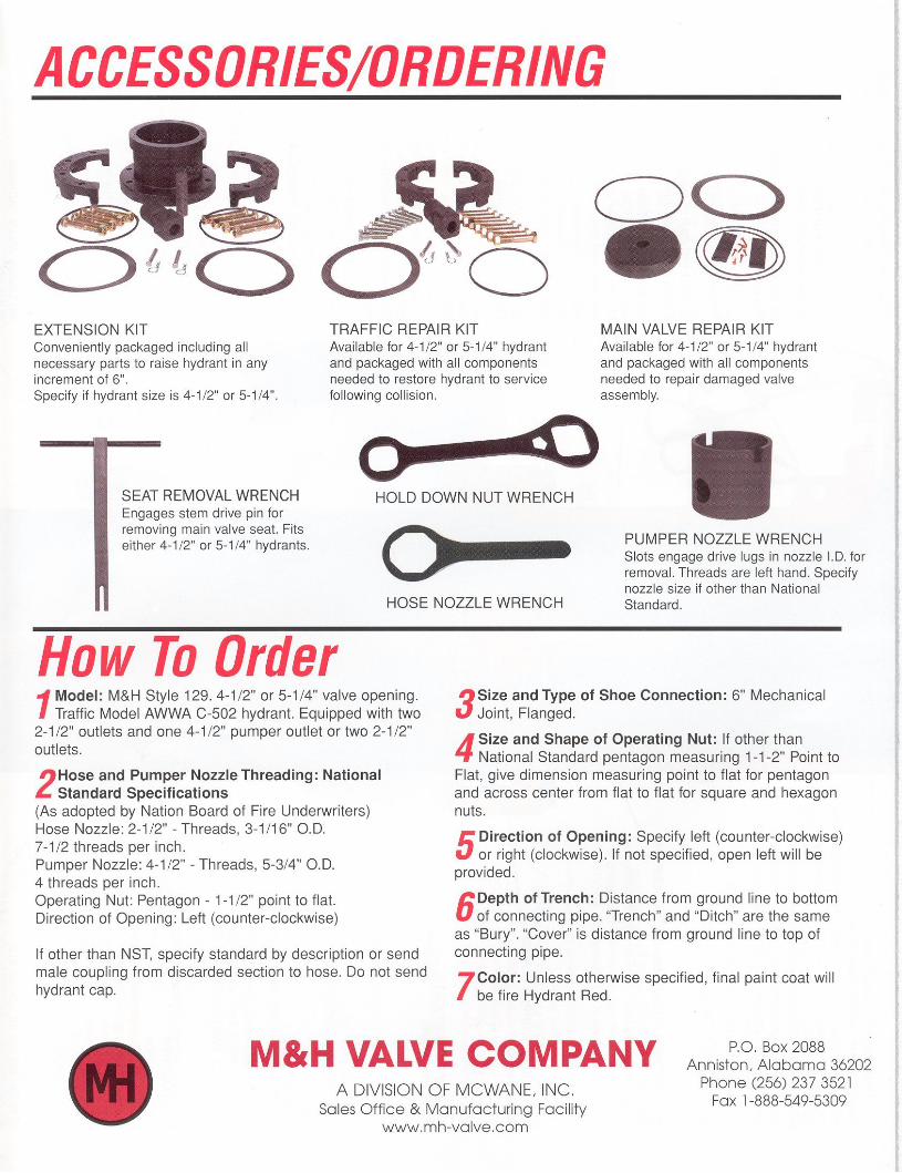


HOW TO ORDER M&H AWWA C502 FIRE HYDRANTS ♦ Model # ♦ Traffic Model ♦ 250 PSI Working Pressure – 500 PSI Hydrostatic Test - AWWA ♦ UL / FM Approved
1. Model: Model # 2. Size of Hydrant Valve Opening: 4 ½” or 5 ¼” 3. Number and size of Hose Nozzels: Two. Usually 2 ½” 4. Hose Nozzle Threading: If other than National Standard,
Specify standard by name or send male coupling from discarded section of hose so that hose connections can be accurately measured. Do not send hydrant cap as this is not always an accurate gauge.
5. Number and Size of Steamer Nozzles: One. Usually 4 ½”
6. Steamer Nozzle Threading: Same instructions as No. 4. above
7. Size of Shoe Connection: 4 ½” VO Hydrants: 4” or 6” e Sho5 ¼” VO Hydrants: 6” shoe
8. Type of Shoe Connection: Mechanical Joint, Flanged
9. Size and Shape of Operating Nut: If other than National Standard pentagon measuring 1 ½” Point to Flat, give dimension measuring Point to Flat for pentagon and across center from flat to flat for square and hexagon nuts.
10. ***Hose and Pumper Caps: Unless other wise specified, hose and pumper cap will match dimensions of operating nut.
11. Direction of Opening: Open left (counter-clockwise) or open right (Clockwise). ***Unless open-right is specified, all hydrants will be made to open / turn to the left.
12. Depth of Trench: Distance from ground line to bottom of connecting pipe. “Trench” and “Ditch” are the same as “Bury”. “Cover” is the distance from the ground line to the top of pipe leading to hydrant shoe.
13. Color: Unless otherwise specified, final paint coat will be Fire Hydrant Red.
14. ***Hydrant Chains: All hydrants are supplied with chains unless you specify otherwise.
15. STORZ Connections: M&H can supply / install NST “STORZ” Connection in place of pumper nozzle.
NATIONAL STANDARD SPECIFICATIONS (As adopted by National Board of Fire Underwriters) Hose Nozzle: 2 ½” I.D.; 3 1/16” O.D.; 7 ½” threads per inch. Steamer Nozzle: 4 ½” I.D.; 5 3/4 “ O.D.; 4 threads per inch. Operating Nut: 1 ½” point to flat. Direction of Opening: Left (counter-clockwise)
July 2005 / M&H C502 Fire Hydrants
M&H VALVE COMPANY Anniston, Alabama
M&H C502 Fire Hydrants
TEN-YEAR LIMITED WARRANTY M&H Valve Company warrants that its AWWA C502 Fire Hydrant will be free from defects in material and workmanship under normal and customary use and maintenance for a period of ten (10) years from the date of purchase, provided the hydrant is installed and maintained according to M&H instructions, and applicable codes. The foregoing warranty does not cover failure of any part or parts from external forces, including, but not limited to, earthquake, vandalism, vehicular or other impact, application of excessive torque to the operating mechanism or frost heave. Should any M&H Valve Company part or parts fail to conform to the foregoing warranty, M&H shall, upon prompt written notice thereof, repair or replace, F.O.B. point of manufacture, such defective part or parts. Purchaser shall, if requested, return the part or parts to M&H, transportation prepaid. Purchaser shall bear all responsibility and expense incurred for removal, reinstallation and shipping in connection with any part supplied under the foregoing warranty. THE FOREGOING WARRANTY IS IN LIEU OF AND EXCLUDES ALL OTHER WARRANTIES NOT EXPRESSLY SET FORTH HEREIN, WHETHER EXPRESS OR IMPLIED BY OPERATION OF LAW OR OTHERWISE, INCLUDING, BUT NOT LIMITED TO, ANY WARRANTIES OF MERCHANTABILITY OR FITNESS. IN NO EVENT SHALL CLOW VALVE COMPANY BE RESPONSIBLE OR LIABLE FOR ANY INCIDENTAL OR CONSEQUENTIAL LOSSES, DAMAGES, OR EXPENSES.
July 2005 / M&H C502 Fire Hydrants