general features - smi-japan.com
TRANSCRIPT
Specifications are subject to change without notice. These products are not intended for use as critical components in life support or nuclear systems.
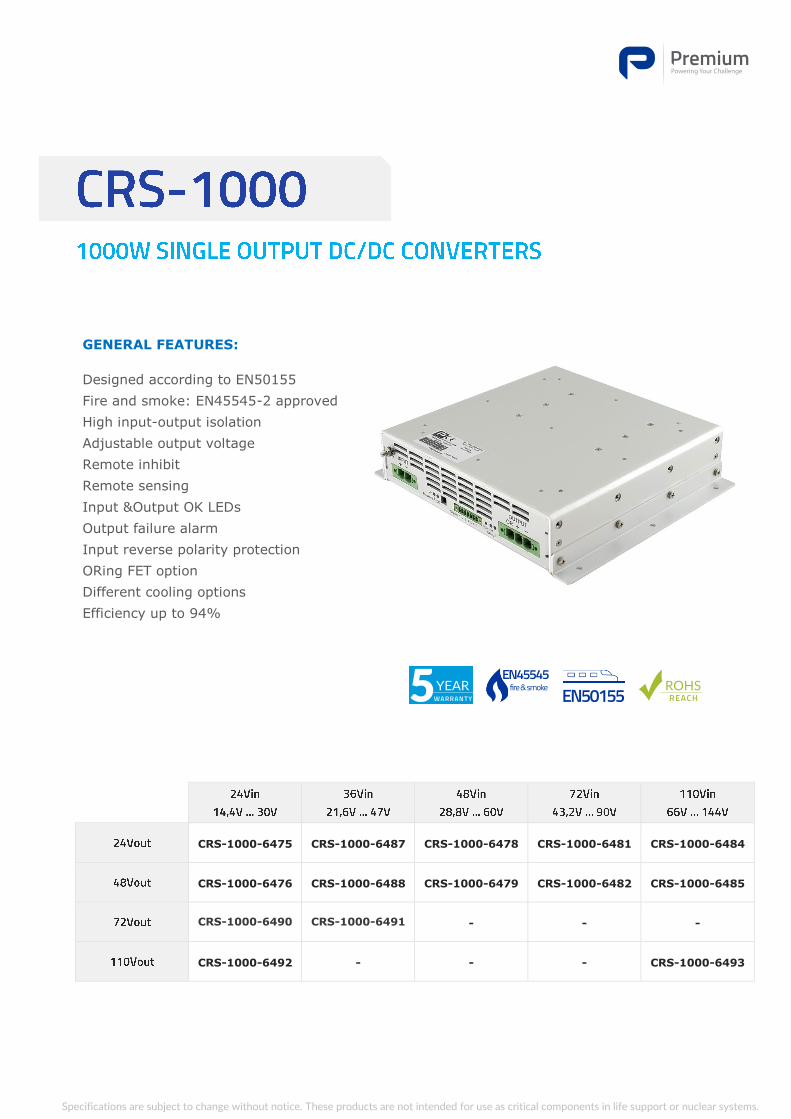
CRS-1000-6475 CRS-1000-6487 CRS-1000-6478 CRS-1000-6481 CRS-1000-6484
CRS-1000-6476 CRS-1000-6488 CRS-1000-6479 CRS-1000-6482 CRS-1000-6485
CRS-1000-6490 CRS-1000-6491 - - -
CRS-1000-6492 - - - CRS-1000-6493
GENERAL FEATURES:
Designed according to EN50155
Fire and smoke: EN45545-2 approved
High input-output isolation
Adjustable output voltage
Remote inhibit
Remote sensing
Input &Output OK LEDs
Output failure alarm
Input reverse polarity protection
ORing FET option
Different cooling options
Efficiency up to 94%
2 / 10
04-11-2019
9502-142-18
CA-540-18
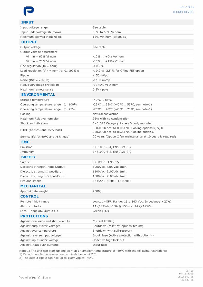
Note-1: The unit can start up and work at an ambient temperature of -40°C with the following restrictions:
1) Do not handle the connection terminals below -25°C.
2) The output ripple can rise up to 150mVpp at -40°C
INPUT
Input voltage range See table
Input undervoltage shutdown 55% to 60% Vi nom
Maximum allowed input ripple 15% Vin nom (EN50155)
OUTPUT
Output voltage See table
Output voltage adjustment
Vi min = 60% Vi nom -10% ... +0% Vo nom
Vi min = 70% Vi nom -10% ... +15% Vo nom
Line regulation (Io = nom) < 0,2 %
Load regulation (Vin = nom Io: 0…100%)) < 0,2 %, 2.5 % for ORing FET option
Ripple < 50 mVpp
Noise (BW = 20MHz) < 100 mVpp
Max. overvoltage protection < 140% Vout nom
Maximum remote sense 0.3V / pole
ENVIRONMENTAL
Storage temperature -40ºC … 85ºC
Operating temperature range Io: 100% -25ºC ... 55ºC (-40°C … 55ºC, see note-1)
Operating temperature range Io :75% -25ºC ... 70ºC (-40°C … 70ºC, see note-1)
Cooling Natural convection
Maximum Relative humidity 95% with no condensation
Shock and vibration EN61373 Category 1 class B body mounted
MTBF (at 40°C and 75% load) 350.000h acc. to IEC61709 Cooling options R, V, D
250.000h acc. to IEC61709 Cooling option C
Service life (at 40°C and 75% load) 20 years (Option C fan maintenance at 10 years is required)
EMC
Emission EN61000-6-4, EN50121-3-2
Immunity EN61000-6-2, EN50121-3-2
SAFETY
Safety EN60950 EN50155
Dielectric strength Input-Output 3000Vac, 4200Vdc 1min.
Dielectric strength Input-Earth 1500Vac, 2100Vdc 1min.
Dielectric strength Output-Earth 1500Vac, 2100Vdc 1min.
Fire and smoke EN45545-2:2013 +A1:2015
MECHANICAL
Approximate weight 2500g
CONTROL
Remote inhibit range Logic: 1=OFF, Range: 15 … 143 Vdc, Impedance > 27kΩ
Alarm contacts 1A @ 24Vdc, 0.3A @ 150Vdc, 1A @ 125Vac
Local: Input OK, Output OK Green LEDs
PROTECTIONS
Against overloads and short-circuits Current limiting
Against output over-voltages Shutdown (reset by input switch off)
Against over-temperature Shutdown with self-recovery
Against reverse input voltage. Input fuse (Active protection with option H)
Against input under-voltage. Under-voltage lock-out
Against Input over-currents Input fuse
3 / 10
04-11-2019
9502-142-18
CA-540-18
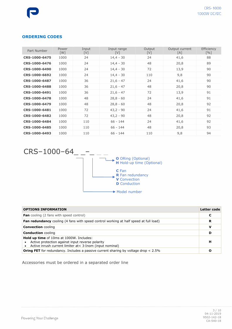
ORDERING CODES
Part Number Power [W]
Input [V]
Input range [V]
Output [V]
Output current [A]
Efficiency [%]
CRS-1000-6475 1000 24 14,4 - 30 24 41,6 88
CRS-1000-6476 1000 24 14,4 - 30 48 20,8 89
CRS-1000-6490 1000 24 14,4 - 30 72 13,9 90
CRS-1000-6692 1000 24 14,4 - 30 110 9,8 90
CRS-1000-6487 1000 36 21,6 - 47 24 41,6 90
CRS-1000-6488 1000 36 21,6 - 47 48 20,8 90
CRS-1000-6491 1000 36 21,6 - 47 72 13,9 91
CRS-1000-6478 1000 48 28,8 - 60 24 41,6 91
CRS-1000-6479 1000 48 28,8 - 60 48 20,8 92
CRS-1000-6481 1000 72 43,2 - 90 24 41,6 91
CRS-1000-6482 1000 72 43,2 - 90 48 20,8 92
CRS-1000-6484 1000 110 66 - 144 24 41,6 92
CRS-1000-6485 1000 110 66 - 144 48 20,8 93
CRS-1000-6493 1000 110 66 - 144 110 9,8 94
OPTIONS INFORMATION Letter code
Fan cooling (2 fans with speed control) C
Fan redundancy cooling (4 fans with speed control working at half speed at full load) R
Convection cooling V
Conduction cooling D
Hold up time of 10ms at 1000W. Includes:
• Active protection against input reverse polarity• Active inrush current limiter at< 3·Inom (input nominal)
H
Oring FET for redundancy. Includes a passive current sharing by voltage drop < 2.5% O
Accessories must be ordered in a separated order line
CRS–1000–64_ _–_ _ _
C Fan R Fan redundancy
V Convection
D Conduction
Model number
O ORing (Optional) H Hold-up time (Optional)
4 / 10
04-11-2019
9502-142-18
CA-540-18
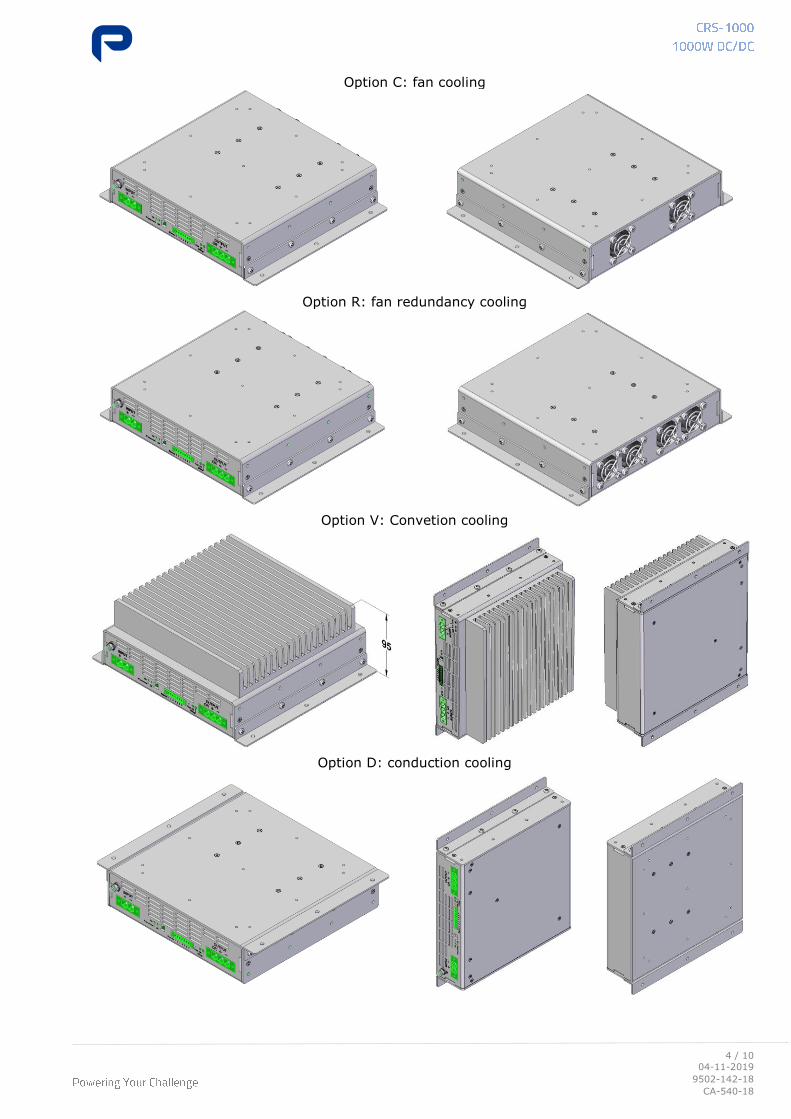
Option C: fan cooling
Option R: fan redundancy cooling
Option V: Convetion cooling
Option D: conduction cooling
5 / 10
04-11-2019
9502-142-18
CA-540-18
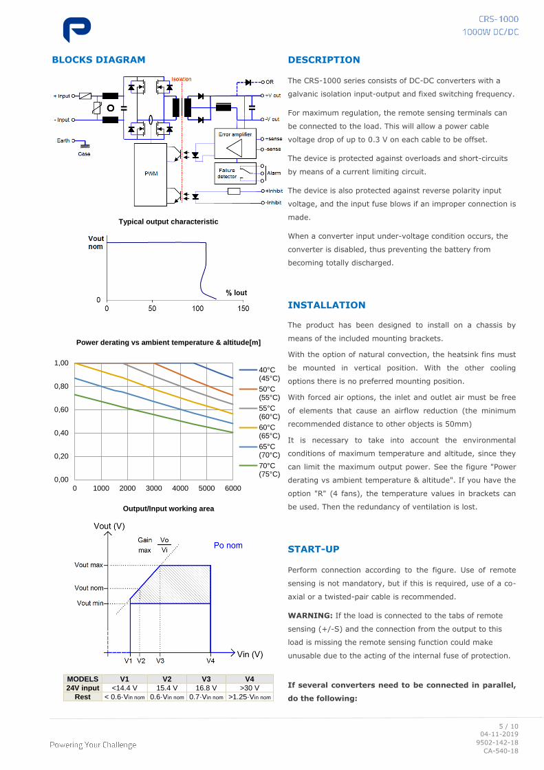
BLOCKS DIAGRAM
Typical output characteristic
Power derating vs ambient temperature & altitude[m]
Output/Input working area
MODELS V1 V2 V3 V4
24V input <14.4 V 15.4 V 16.8 V >30 V
Rest < 0.6·Vin nom 0.6·Vin nom 0.7·Vin nom >1.25·Vin nom
DESCRIPTION
The CRS-1000 series consists of DC-DC converters with a
galvanic isolation input-output and fixed switching frequency.
For maximum regulation, the remote sensing terminals can
be connected to the load. This will allow a power cable
voltage drop of up to 0.3 V on each cable to be offset.
The device is protected against overloads and short-circuits
by means of a current limiting circuit.
The device is also protected against reverse polarity input
voltage, and the input fuse blows if an improper connection is
made.
When a converter input under-voltage condition occurs, the
converter is disabled, thus preventing the battery from
becoming totally discharged.
INSTALLATION
The product has been designed to install on a chassis by
means of the included mounting brackets.
With the option of natural convection, the heatsink fins must
be mounted in vertical position. With the other cooling
options there is no preferred mounting position.
With forced air options, the inlet and outlet air must be free
of elements that cause an airflow reduction (the minimum
recommended distance to other objects is 50mm)
It is necessary to take into account the environmental
conditions of maximum temperature and altitude, since they
can limit the maximum output power. See the figure "Power
derating vs ambient temperature & altitude". If you have the
option "R" (4 fans), the temperature values in brackets can
be used. Then the redundancy of ventilation is lost.
START-UP
Perform connection according to the figure. Use of remote
sensing is not mandatory, but if this is required, use of a co-
axial or a twisted-pair cable is recommended.
WARNING: If the load is connected to the tabs of remote
sensing (+/-S) and the connection from the output to this
load is missing the remote sensing function could make
unusable due to the acting of the internal fuse of protection.
If several converters need to be connected in parallel,
do the following:
0,00
0,20
0,40
0,60
0,80
1,00
0 1000 2000 3000 4000 5000 6000
40°C(45°C)
50°C(55°C)
55°C(60°C)
60°C(65°C)
65°C(70°C)
70°C(75°C)
6 / 10
04-11-2019
9502-142-18
CA-540-18
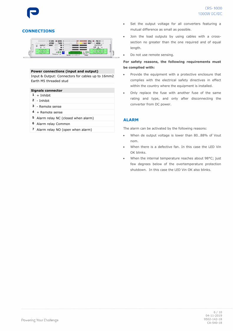
CONNECTIONS
Power connections (input and output)
Input & Output: Connectors for cables up to 16mm2
Earth M5 threaded stud
Signals connector
1 + Inhibit
2 - Inhibit
3 - Remote sense
4 + Remote sense
5 Alarm relay NC (closed when alarm)
6 Alarm relay Common
7 Alarm relay NO (open when alarm)
• Set the output voltage for all converters featuring a
mutual difference as small as possible.
• Join the load outputs by using cables with a cross-
section no greater than the one required and of equal
length.
• Do not use remote sensing.
For safety reasons, the following requirements must
be complied with:
• Provide the equipment with a protective enclosure that
complies with the electrical safety directives in effect
within the country where the equipment is installed.
• Only replace the fuse with another fuse of the same
rating and type, and only after disconnecting the
converter from DC power.
ALARM
The alarm can be activated by the following reasons:
• When de output voltage is lower than 80…88% of Vout
nom.
• When there is a defective fan. In this case the LED Vin
OK blinks.
• When the internal temperature reaches about 98°C; just
few degrees below of the overtemperature protection
shutdown. In this case the LED Vin OK also blinks.
7 / 10
04-11-2019
9502-142-18
CA-540-18
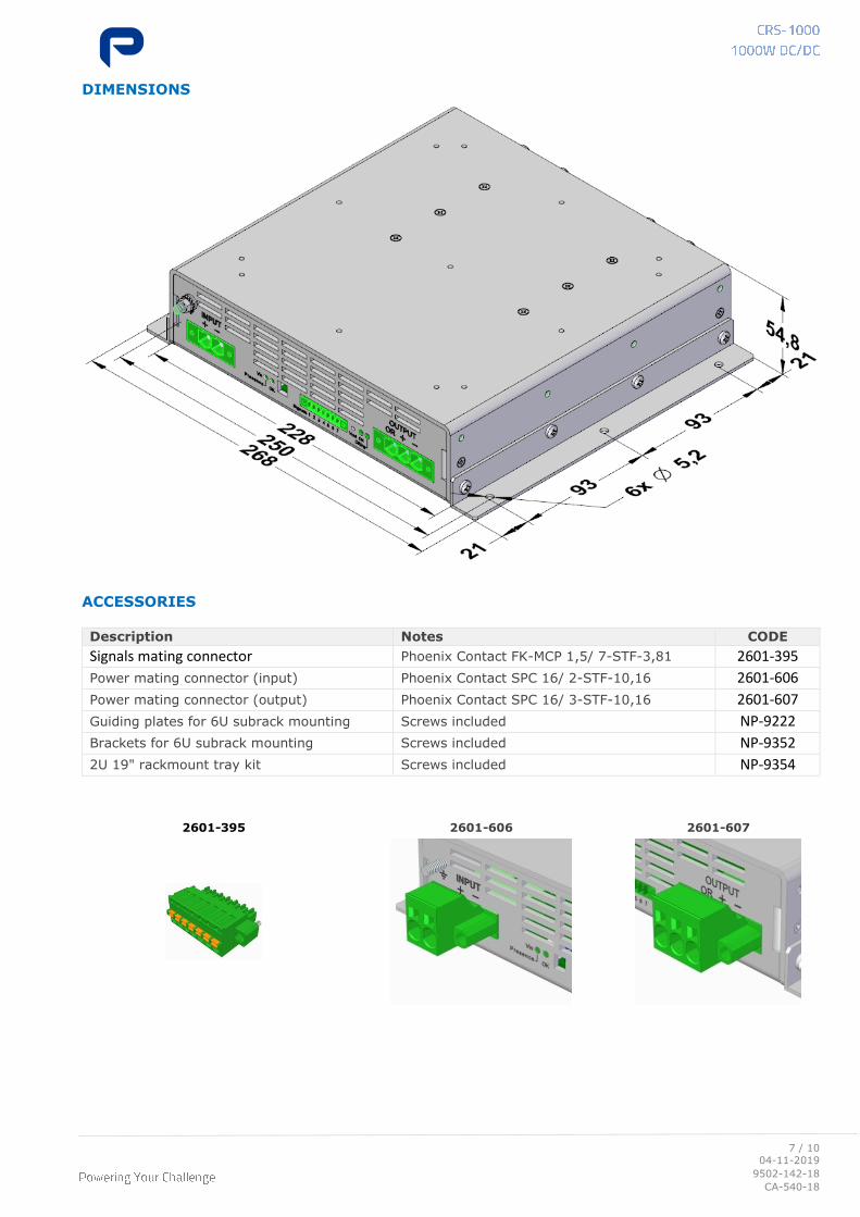
DIMENSIONS
ACCESSORIES
Description Notes CODE
Signals mating connector Phoenix Contact FK-MCP 1,5/ 7-STF-3,81 2601-395
Power mating connector (input) Phoenix Contact SPC 16/ 2-STF-10,16 2601-606
Power mating connector (output) Phoenix Contact SPC 16/ 3-STF-10,16 2601-607
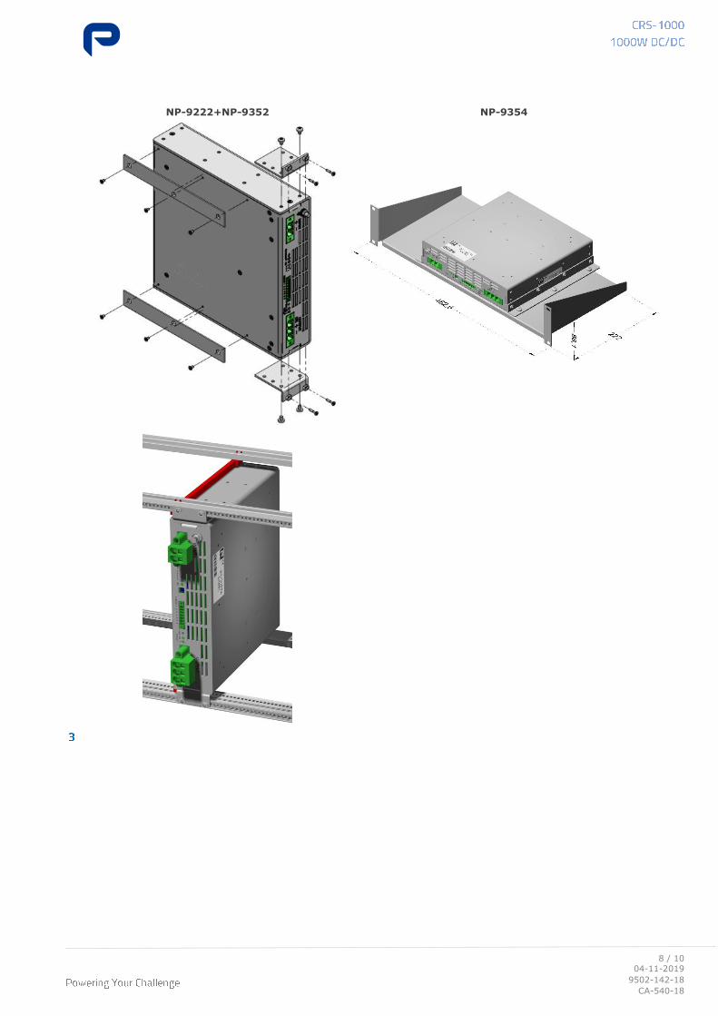
Guiding plates for 6U subrack mounting Screws included NP-9222
Brackets for 6U subrack mounting Screws included NP-9352
2U 19" rackmount tray kit Screws included NP-9354
2601-395 2601-606 2601-607
9 / 10
04-11-2019
9502-142-18
CA-540-18
EU DECLARATION OF CONFORMITY
The undersigned, representing the following:
Manufacturer: PREMIUM, S. A.,
Address: C/ Dolors Aleu 19-21, 08908 L’Hospitalet de Llobregat, SPAIN
herewith declares that the product:
Type: DC/DC converter
Models: CRS-1000-6475 ... 6493
is in conformity with the provisions of the following EU directive(s):
2014/35/EU Low voltage
2014/30/EU Electromagnetic compatibility
2011/65/EU Restriction of the use of certain hazardous substances in electrical and
electronic equipment (RoHS)
and that standards and/or technical specifications referenced overleaf have been applied:
EN 60950-1: 2005 Safety. Information technology equipment
EN 62368-1: 2014 Safety. Audio/video, information and communication technology equipment
EN 61000-6-3: 2007 Generic emission standard
EN 61000-6-2: 2005 Generic immunity standard
EN 50155: 2017* Railway applications. Electronic equipment used on rolling stock material
EN 50121-3-2: 2016* Railway applications. EMC Rolling stock equipment
EN 50121-4: 2016* Railway applications. EMC of the signalling and telecommunications apparatus
* See annexe
CE marking year: 2018
Notes:
For the fulfillment of this declaration the product must be used only for the aim that has been
conceived, considering the limitations established in the instructions manual or datasheet.
L’Hospitalet de Llobregat, 28-08-2019
Jordi Gazo
Chief Executive Officer
10 / 10
04-11-2019
9502-142-18
CA-540-18
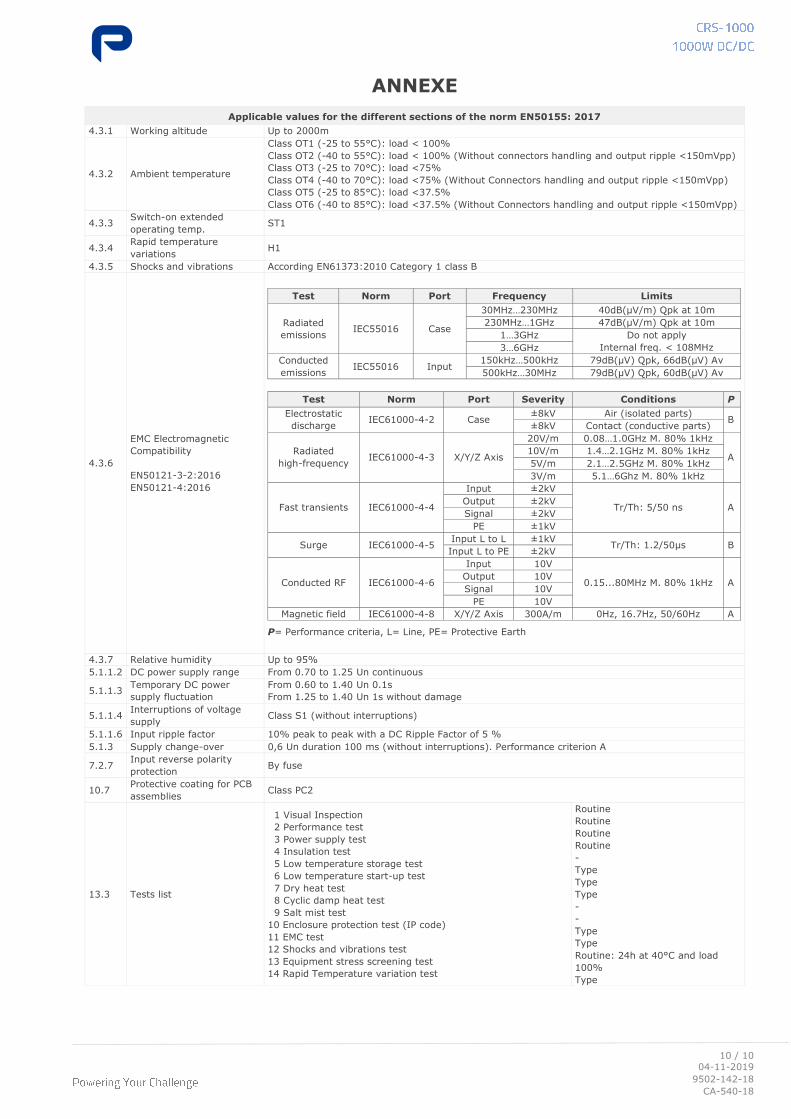
ANNEXE
Applicable values for the different sections of the norm EN50155: 2017
4.3.1 Working altitude Up to 2000m
4.3.2 Ambient temperature
Class OT1 (-25 to 55°C): load < 100%
Class OT2 (-40 to 55°C): load < 100% (Without connectors handling and output ripple <150mVpp)
Class OT3 (-25 to 70°C): load <75%
Class OT4 (-40 to 70°C): load <75% (Without Connectors handling and output ripple <150mVpp)
Class OT5 (-25 to 85°C): load <37.5%
Class OT6 (-40 to 85°C): load <37.5% (Without Connectors handling and output ripple <150mVpp)
4.3.3 Switch-on extended
operating temp. ST1
4.3.4 Rapid temperature
variations H1
4.3.5 Shocks and vibrations According EN61373:2010 Category 1 class B
4.3.6
EMC Electromagnetic
Compatibility
EN50121-3-2:2016
EN50121-4:2016
Test Norm Port Frequency Limits
Radiated
emissions IEC55016 Case
30MHz…230MHz 40dB(µV/m) Qpk at 10m
230MHz…1GHz 47dB(µV/m) Qpk at 10m
1…3GHz Do not apply
Internal freq. < 108MHz 3…6GHz
Conducted
emissions IEC55016 Input
150kHz…500kHz 79dB(µV) Qpk, 66dB(µV) Av
500kHz…30MHz 79dB(µV) Qpk, 60dB(µV) Av
Test Norm Port Severity Conditions P
Electrostatic
discharge IEC61000-4-2 Case
±8kV Air (isolated parts) B
±8kV Contact (conductive parts)
Radiated
high-frequency IEC61000-4-3 X/Y/Z Axis
20V/m 0.08…1.0GHz M. 80% 1kHz
A 10V/m 1.4…2.1GHz M. 80% 1kHz
5V/m 2.1…2.5GHz M. 80% 1kHz
3V/m 5.1…6Ghz M. 80% 1kHz
Fast transients IEC61000-4-4
Input ±2kV
Tr/Th: 5/50 ns A Output ±2kV
Signal ±2kV
PE ±1kV
Surge IEC61000-4-5 Input L to L ±1kV
Tr/Th: 1.2/50µs B Input L to PE ±2kV
Conducted RF IEC61000-4-6
Input 10V
0.15...80MHz M. 80% 1kHz A Output 10V
Signal 10V
PE 10V
Magnetic field IEC61000-4-8 X/Y/Z Axis 300A/m 0Hz, 16.7Hz, 50/60Hz A
P= Performance criteria, L= Line, PE= Protective Earth
4.3.7 Relative humidity Up to 95%
5.1.1.2 DC power supply range From 0.70 to 1.25 Un continuous
5.1.1.3 Temporary DC power
supply fluctuation
From 0.60 to 1.40 Un 0.1s
From 1.25 to 1.40 Un 1s without damage
5.1.1.4 Interruptions of voltage
supply Class S1 (without interruptions)
5.1.1.6 Input ripple factor 10% peak to peak with a DC Ripple Factor of 5 %
5.1.3 Supply change-over 0,6 Un duration 100 ms (without interruptions). Performance criterion A
7.2.7 Input reverse polarity
protection By fuse
10.7 Protective coating for PCB
assemblies Class PC2
13.3 Tests list
1 Visual Inspection
2 Performance test
3 Power supply test
4 Insulation test
5 Low temperature storage test
6 Low temperature start-up test
7 Dry heat test
8 Cyclic damp heat test
9 Salt mist test
10 Enclosure protection test (IP code)
11 EMC test
12 Shocks and vibrations test
13 Equipment stress screening test
14 Rapid Temperature variation test
Routine
Routine
Routine
Routine
-
Type
Type
Type
-
-
Type
Type
Routine: 24h at 40°C and load
100%
Type