general features:customer.alphatechnologies.eu/compas/user_guide/user... · web view7.6up converter...
TRANSCRIPT

Alpha Technologies S.A.Boulevard de l’Europe 131
B-1301 WavreBelgium
www.alphatechnologies.eu
COMP@S USER'S GUIDE
Your Power Solutions Partner

Alpha Technologies S.A.www.alphatechnologies.eu Comp@s User Guide
Boulevard de l’Europe 131B-1301 Wavre
Belgium
TABLE OF CONTENTS
1 About this guide...................................7
2 Overview...........................................8
2.1 Architecture and Features.................................................................................................82.1.1 General Features:.................................................................................................................9
2.2 Block Diagram of Energy Systems managed by [email protected]
2.3 DC System Overview........................................................................................................102.3.1 DC Power System Principles..............................................................................................112.3.2 General Information on MCU..............................................................................................112.3.3 Mode Of Operation.............................................................................................................122.3.4 Battery Temperature Compensation...................................................................................122.3.5 Battery Charge Current Control..........................................................................................132.3.6 Battery Low Voltage Disconnect Operation (LVD)..............................................................142.3.7 DC System Alarms Overview.............................................................................................142.3.8 Battery Test.........................................................................................................................162.3.9 Boost Mode.........................................................................................................................172.3.10 List Of Possible Events.......................................................................................................17
2.4 Some Comp@s Compatible Devices and Equipments.................................................172.4.1 Site Controller.....................................................................................................................172.4.2 DC Systems........................................................................................................................182.4.3 Remote Power Feeding Systems.......................................................................................182.4.4 Inverter Systems.................................................................................................................19
3 Getting Started...................................21
3.1 Connecting the Comp@s Web Server over Ethernet....................................................21
3.2 Connecting the Comp@s Web Server over USB...........................................................23
3.3 The Web Interface.............................................................................................................243.3.1 Site......................................................................................................................................263.3.2 Dashboard..........................................................................................................................473.3.3 Reporting............................................................................................................................483.3.4 Alarms/Events.....................................................................................................................503.3.5 Inventory.............................................................................................................................503.3.6 Files....................................................................................................................................523.3.7 Controller............................................................................................................................523.3.8 Modifying values.................................................................................................................553.3.9 Changing the Network Configuration..................................................................................573.3.10 Saving The Changes..........................................................................................................603.3.11 Getting some help about the elements...............................................................................61
3.4 The Comp@s SNMP Agent..............................................................................................63
1

Alpha Technologies S.A.www.alphatechnologies.eu
Alpha Technologies S.A.www.alphatechnologies.eu
Comp@s User GuideBoulevard de l’Europe 131
B-1301 WavreBelgium
4 Functionalities......................................68
4.1 User Access Management...............................................................................................68
4.2 Save / Load configuration................................................................................................70
4.3 Automatic events saving.................................................................................................70
4.4 Date and Time Management............................................................................................704.4.1 Real Time Clock..................................................................................................................704.4.2 Time zone and Daylight Saving Time.................................................................................714.4.3 (S)NTP Time Protocol.........................................................................................................72
4.5 Software Upgrade Management......................................................................................724.5.1 Upgrading the Comp@s Software......................................................................................724.5.2 Upgrading a Firmware with Comp@s.................................................................................774.5.3 Upgrading The Operating System......................................................................................79
4.6 Reset Factory Settings.....................................................................................................81
4.7 Copying configuration from a system to another.........................................................82
4.8 PLC Functionalities..........................................................................................................834.8.1 Syntax.................................................................................................................................834.8.2 Examples of Boolean Conditions........................................................................................854.8.3 Examples of Mathematical Expressions.............................................................................854.8.4 PLC License Package.........................................................................................................86
4.9 Translating The Web Interface........................................................................................87
4.10 Replacing a Rectifier in a DC System.............................................................................88
4.11 Measuring Power and Energy.........................................................................................88
4.12 Mobile Compliant..............................................................................................................90
4.13 Alarm Acknowledgement.................................................................................................91
4.14 Email..................................................................................................................................92
5 Software Interfaces...............................94
5.1 Web Server........................................................................................................................945.1.1 ETSI Protocol......................................................................................................................945.1.2 Retrieving XML files............................................................................................................985.1.3 Retrieving data records in CSV format.............................................................................1005.1.4 HTTP GET of any description, data, configuration, etc....................................................1005.1.5 HTTP POST to configure and control...............................................................................101
5.2 FTP Server.......................................................................................................................1045.2.1 Connecting the Comp@s FTP Server..............................................................................1045.2.2 Changing default login and password...............................................................................104
5.3 Modbus Slave..................................................................................................................1055.3.1 Discrete Inputs (Read Only).............................................................................................105
2

Alpha Technologies S.A.www.alphatechnologies.eu
Alpha Technologies S.A.www.alphatechnologies.eu
Comp@s User GuideBoulevard de l’Europe 131
B-1301 WavreBelgium
5.3.2 Input Registers (Read Only).............................................................................................1075.3.3 Discrete Coils Table (Command)......................................................................................109
5.4 SNMP Agent....................................................................................................................1105.4.1 Using and Configuring SNMP traps.................................................................................110
5.5 XML Event Posting (ETSI)..............................................................................................112
6 CAN Bus related information......................117
6.1 CAN Bus - The internal field bus...................................................................................117
6.2 Connecting multiple rectifier shelves together...........................................................1186.2.1 Multiple Shelves working in parallel..................................................................................1186.2.2 Multiple Shelves Independent...........................................................................................119
7 Equipment Tables...................................120
7.1 Site Tables.......................................................................................................................1207.1.1 COMPAS..........................................................................................................................120
7.2 DC System Tables...........................................................................................................1347.2.1 ADIO 10 For Cordex Control............................................................................................1347.2.2 ADIO 12 AS MCU.............................................................................................................1537.2.3 MCU1X6...........................................................................................................................1687.2.4 MCU1X6M3......................................................................................................................1857.2.5 MCU0024..........................................................................................................................1997.2.6 MCU0348LP.....................................................................................................................2167.2.7 MCU0348M4.....................................................................................................................2317.2.8 MCU0348M4 / MCU0348LP.............................................................................................2457.2.9 MCU0548M4.....................................................................................................................2617.2.10 MCU0948DW....................................................................................................................2777.2.11 MCU0948M4 / MCU0948M4LP........................................................................................2947.2.12 MCU1848M3 / MCU1848M3D..........................................................................................3107.2.13 MCU1848M6.....................................................................................................................3247.2.14 MCU3048M6.....................................................................................................................3407.2.15 MCU3096M6.....................................................................................................................3597.2.16 MCU30110M6...................................................................................................................3767.2.17 MCU30125M6...................................................................................................................394
7.3 Rectifier Tables...............................................................................................................4117.3.1 CAR0548TN......................................................................................................................4117.3.2 CAR0948TN-1A / CAR0948TN-2A...................................................................................4137.3.3 CAR0948TN-3A................................................................................................................4157.3.4 CAR1024TP......................................................................................................................4187.3.5 CAR1048TN-1A................................................................................................................4207.3.6 CAR1048TN-2A................................................................................................................4237.3.7 CAR1548TN......................................................................................................................4267.3.8 CAR1848TN-1A................................................................................................................4277.3.9 CAR1848TN-2A................................................................................................................4287.3.10 CAR2648TN......................................................................................................................4307.3.11 CAR30110TP....................................................................................................................4317.3.12 CAR30125TP....................................................................................................................4347.3.13 CDC1548TN.....................................................................................................................437
3

Alpha Technologies S.A.www.alphatechnologies.eu
Alpha Technologies S.A.www.alphatechnologies.eu
Comp@s User GuideBoulevard de l’Europe 131
B-1301 WavreBelgium
7.3.14 Cordex 2.4KW...................................................................................................................4387.3.15 Cordex 4KW......................................................................................................................4417.3.16 CXRF48-4kW....................................................................................................................4437.3.17 CXRF 48-300W.................................................................................................................4467.3.18 ECOR0348........................................................................................................................449
7.4 Sensors And Actuators Tables.....................................................................................4527.4.1 ADIO 7..............................................................................................................................4527.4.2 ADIO 8..............................................................................................................................4647.4.3 ADIO 9..............................................................................................................................4737.4.4 ADIO 10............................................................................................................................4797.4.5 ADIO 12............................................................................................................................4887.4.6 ADIO 13............................................................................................................................4957.4.7 ADIO SP0151...................................................................................................................5007.4.8 ADIO SP0155/01..............................................................................................................5127.4.9 ADIO SP0155/02..............................................................................................................5287.4.10 BIOM.................................................................................................................................5527.4.11 SAM0948..........................................................................................................................559
7.5 Remote Power Feeding System Tables........................................................................5697.5.1 CEM03_Remote_Power_Feeding_System......................................................................5697.5.2 CEM03 Remote Power Feeding_System.........................................................................570
7.6 Up Converter System Tables.........................................................................................5717.6.1 CEM03_Up_Converter_System.......................................................................................5717.6.2 CEM03 Up Converter_System.........................................................................................578
7.7 Remote Site Tables.........................................................................................................5857.7.1 CEM03_Remote_Site.......................................................................................................5857.7.2 CEM03 Remote Site.........................................................................................................590
7.8 Inverter Tables................................................................................................................5947.8.1 Inverter Module (T2S).......................................................................................................594
7.9 Inverter System Tables..................................................................................................5987.9.1 Inverter System (T2S).......................................................................................................598
8 Licenses.........................................629
8.1 The Comp@s license packages....................................................................................6298.1.1 The Battery Package........................................................................................................6298.1.2 The Asset Package...........................................................................................................6298.1.3 The PLC Package.............................................................................................................6298.1.4 The Modbus Package.......................................................................................................6308.1.5 License currently in use....................................................................................................630
8.2 How can I upgrade my license?....................................................................................630
8.3 How is the license stored?............................................................................................630
9 Software Release Components......................632
9.1 System bootloader..........................................................................................................632
4
Alpha Technologies S.A.www.alphatechnologies.eu
Alpha Technologies S.A.www.alphatechnologies.eu
Comp@s User GuideBoulevard de l’Europe 131
B-1301 WavreBelgium
9.2 The Operating System....................................................................................................632
9.3 Comp@s Starter Executable..........................................................................................633
9.4 Comp@s Executable......................................................................................................6339.4.1 C Drivers...........................................................................................................................6339.4.2 Environment Configuration...............................................................................................6349.4.3 License..............................................................................................................................6349.4.4 Translation Dictionary.......................................................................................................6349.4.5 Site Object........................................................................................................................6349.4.6 Decode CAN Msg.............................................................................................................6359.4.7 Web Server Interface........................................................................................................6359.4.8 SNMP Management..........................................................................................................6359.4.9 Process Scheduled Tasks................................................................................................6359.4.10 Inventory Management and Equipment Mounting............................................................6359.4.11 Alarm Set-up and Clearance............................................................................................6369.4.12 System and Application Configuration..............................................................................6369.4.13 Data Record Management................................................................................................6369.4.14 Equipment Emulation........................................................................................................636
9.5 Comp@s FTP Server Executable..................................................................................636
10 Software Changelog.................................637
10.1 .NET Executable Versioning..........................................................................................637
10.2 Comp@s Changelog.......................................................................................................637
11 Emulation Capabilities...........................657
11.1 What is the Comp@s emulator?....................................................................................657
11.2 What are the requirements?..........................................................................................657
11.3 How to run the emulator?..............................................................................................657
11.4 How to use the emulator?..............................................................................................658
11.5 Simulating a network of Comp@s system...................................................................658
11.6 Where can I get the emulator?......................................................................................658
11.7 Remarks...........................................................................................................................658
12 Frequently Asked Questions..........................660
12.1 USB Connection Troubles.............................................................................................660
13 Support..........................................663
5

Alpha Technologies S.A.www.alphatechnologies.eu
Alpha Technologies S.A.www.alphatechnologies.eu
Comp@s User GuideBoulevard de l’Europe 131
B-1301 WavreBelgium
6

Alpha Technologies S.A.www.alphatechnologies.eu
Alpha Technologies S.A.www.alphatechnologies.eu
Comp@s User GuideBoulevard de l’Europe 131
B-1301 WavreBelgium
1 ABOUT THIS GUIDE
The information and pictures within this guide is believed to be true at the time of publication however Alpha Technologies S.A. accepts no responsibility to consequences from printing errors or inaccuracies. The information, pictures, drawings and specifications contained herein are subject to change without notice.
Guide History:
Date Edition Notes
… … See previous manuals.
17 December 2012 10 Updated for release 0.114.0.7
16 January 2013 11 Updated for release 0.116.0.3
21 January 2013 12 Updated for release 0.117.0.3
21 February 2013 13 Updated for release 0.119.0.3
13 June 2013 14 Updated for release 0.123.0.3
04 August 2014 15 Updated for release 2.11.0.3 (First official version for 2.x)
Contact informationAlpha Technologies S.A.
Boulevard de l’Europe 131
1301 Wavre
Belgium
Tel: +32 (0)10 438 510
Fax: +32 (0)10 438 213
Web: www.alphatechnologies.eu
7

Alpha Technologies S.A.www.alphatechnologies.eu
Alpha Technologies S.A.www.alphatechnologies.eu
Comp@s User GuideBoulevard de l’Europe 131
B-1301 WavreBelgium
2 OVERVIEW
Architecture and Features
Block Diagram of Energy Systems managed by Comp@s
DC System Overview.
2.1 Architecture and FeaturesMagell@n Comp@s is the product name of our new controller. It consists in a new platform extending the range of applications of a traditional dc-system shelf controller. Comp@s product is a “site” monitoring, allowing the supervision and the control of:
Environmental issues: temperature, humidity, water detection, etc.
Access control issues: RFID badge reader, door lock, open door detection, etc.
Integrity issues: vandalism and traffic accident detection
Whatever you may need, just ask us.
This solution targets large network infrastructure, also with heterogeneous architecture. It is the ideal solution for access networks cabinet monitoring and control. This platform allows customization to satisfy your needs.
Comp@s can be easily integrated in your management system. It supports broad range of standard communication protocols and do not request any proprietary application.
This site monitoring is a powerful tool for OPEX (OPerating EXpenditures) reduction. It lowers energy costs, reduce field interventions and provide data logging and statistics facilities.
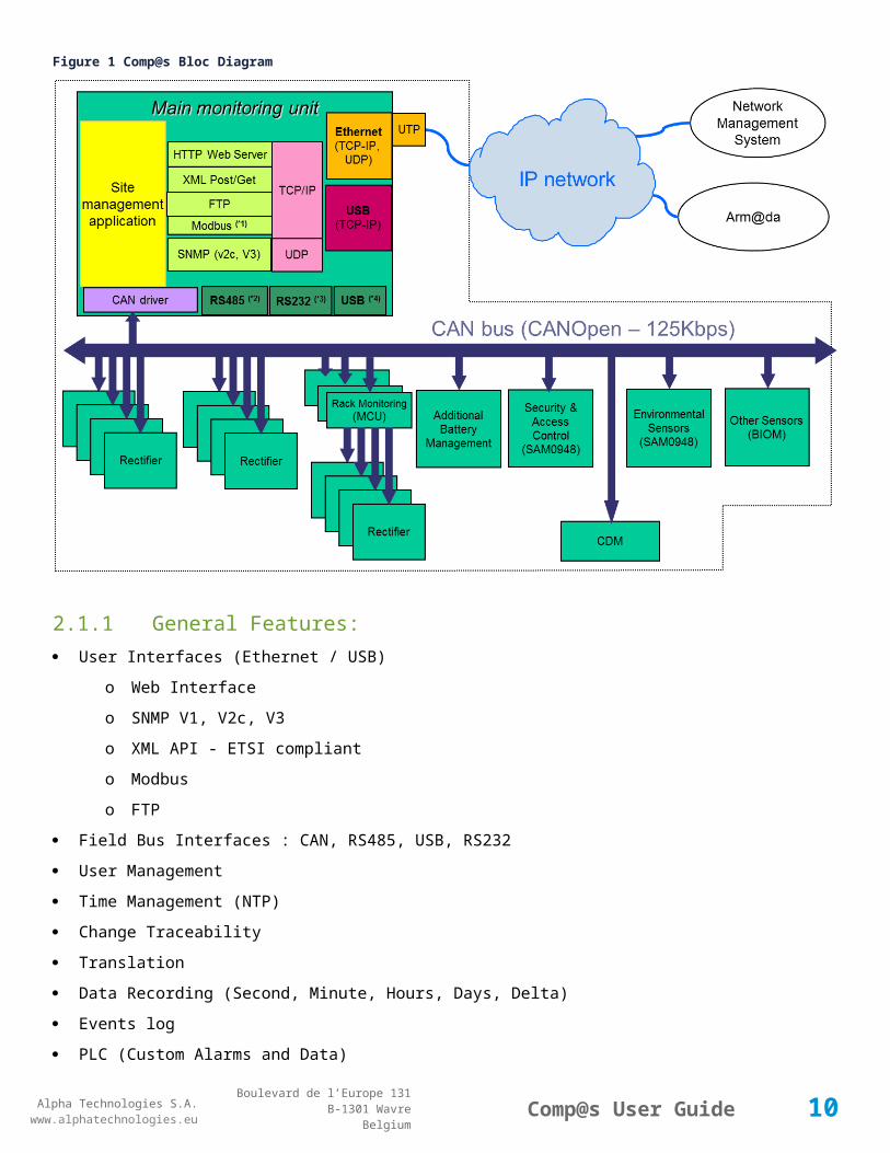
Comp@s has a very flexible hardware and software architecture, as shown on the following figure. Thanks to this architecture, our platform is open, scalable and evolvable. All our devices (rectifiers and extensions) are connected to a reliable digital bus (CAN Bus). This allows the main monitoring unit to retrieve information, configure and command the devices. This main monitoring unit is running the site management application. This site management application provides multiple communication interfaces: Web server, XML services and SNMP. These interfaces are available over Ethernet and also over USB for local connection (Rem: SNMP not available over USB). All the interfaces allowing access to the monitoring are secured. One administrator and up to five users can have different access and privileges:
8

Alpha Technologies S.A.www.alphatechnologies.eu
Alpha Technologies S.A.www.alphatechnologies.eu
Comp@s User GuideBoulevard de l’Europe 131
B-1301 WavreBelgium
Figure 1 Comp@s Bloc Diagram
2.1.1 General Features: User Interfaces (Ethernet / USB)
o Web Interface
o SNMP V1, V2c, V3
o XML API - ETSI compliant
o Modbus
o FTP
Field Bus Interfaces : CAN, RS485, USB, RS232
User Management
Time Management (NTP)
Change Traceability
Translation
Data Recording (Second, Minute, Hours, Days, Delta)
Events log
PLC (Custom Alarms and Data)
Customizable - Renaming
Compatible With Arm@da, or any other ETSI compatible NMS.
9
Alpha Technologies S.A.www.alphatechnologies.eu
Alpha Technologies S.A.www.alphatechnologies.eu
Comp@s User GuideBoulevard de l’Europe 131
B-1301 WavreBelgium
Remote Comp@s Upgrade
Backward compatible on Upgrade
Factory Configuration
License Model (You pay what you need)
Ready for customization on specific projects
2.2 Block Diagram of Energy Systems managed by Comp@s
The following figure schematizes a sub-shelf which integrates 4 rectifiers, a controller unit, an extension card to interface multiple sensors/actuators and the distribution, including the breakers. The typical size of such a sub-shelf is 2U height, and 19” wide:Figure 2 Schematic of the inside of a cabinet
2.3 DC System Overview DC Power System Principles
General Information on MCU
Mode Of Operation
Battery Temperature Compensation
Battery Charge Current Control
10

Alpha Technologies S.A.www.alphatechnologies.eu
Alpha Technologies S.A.www.alphatechnologies.eu
Comp@s User GuideBoulevard de l’Europe 131
B-1301 WavreBelgium
Battery Low Voltage Disconnect Operation (LVD)
DC System Alarms Overview
Battery Test
Boost Mode
List Of Possible Events.
2.3.1 DC Power System PrinciplesA DC system is a system converting AC power to DC power.
It is composed of:
Rectifiers
AC distribution
DC distribution
Battery(ies), avoiding application interruption.
MCU (Monitoring Control Unit).
The following diagram is a classical representation of a DC system:Figure 3 DC System
The following sub-chapters include a high level description of generic functionalities. More information should be available on the user manual of the specific system you are using.
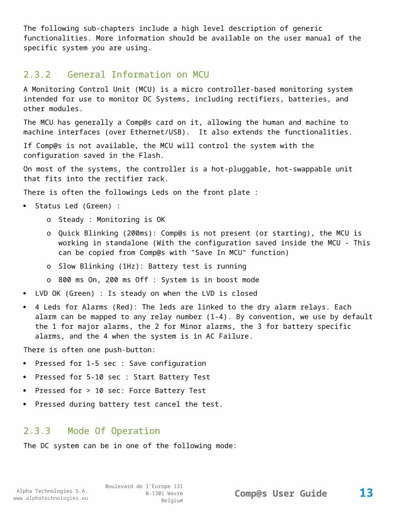
2.3.2 General Information on MCUA Monitoring Control Unit (MCU) is a micro controller-based monitoring system intended for use to monitor DC Systems, including rectifiers, batteries, and other modules.
The MCU has generally a Comp@s card on it, allowing the human and machine to machine interfaces (over Ethernet/USB). It also extends the functionalities.
If Comp@s is not available, the MCU will control the system with the configuration saved in the Flash.
On most of the systems, the controller is a hot-pluggable, hot-swappable unit that fits into the rectifier rack.
There is often the followings Leds on the front plate :
Status Led (Green) :
11

Alpha Technologies S.A.www.alphatechnologies.eu
Alpha Technologies S.A.www.alphatechnologies.eu
Comp@s User GuideBoulevard de l’Europe 131
B-1301 WavreBelgium
o Steady : Monitoring is OK
o Quick Blinking (200ms): Comp@s is not present (or starting), the MCU is working in standalone (With the configuration saved inside the MCU - This can be copied from Comp@s with "Save In MCU" function)
o Slow Blinking (1Hz): Battery test is running
o 800 ms On, 200 ms Off : System is in boost mode
LVD OK (Green) : Is steady on when the LVD is closed
4 Leds for Alarms (Red): The leds are linked to the dry alarm relays. Each alarm can be mapped to any relay number (1-4). By convention, we use by default the 1 for major alarms, the 2 for Minor alarms, the 3 for battery specific alarms, and the 4 when the system is in AC Failure.
There is often one push-button:
Pressed for 1-5 sec : Save configuration
Pressed for 5-10 sec : Start Battery Test
Pressed for > 10 sec: Force Battery Test
Pressed during battery test cancel the test.
2.3.3 Mode Of OperationThe DC system can be in one of the following mode:
Float : the output voltage is set to the float voltage setting. It can be automatically adjusted by the temperature compensation or the current limitation.
Boost : the output voltage is set to the boost voltage setting. It can be automatically adjusted by the temperature compensation or the current limitation.
Battery Test : the battery is being tested. The voltage is going down. Alarm like "Bus Voltage Low" can be generated.
Ac Failure : all the rectifiers are not powered. The battery is discharging.
Safe : the system can go to safe when when there is communication problems or when the voltage/current/temperature sense are not connected correctly.
2.3.4 Battery Temperature Compensation BTC: General Overview
BTC: Configuration Parameters
Theory Of Battery Temperature Compensation.
2.3.4.1 BTC: General OverviewThe controller includes a control loop that compares the bus voltage with a reference value, and pilots on the rectifiers programming voltage accordingly. It also measures the battery temperature through an external temperature probe (NTC 10K). This measurement, together with the “DC Bus Float Voltage at 25°C” and “Battery Temperature Compensation” configuration, determines the reference voltage. The maximum compensation can be configured.
The Battery Temperature Compensation is regulated by the MCU. The configuration is stored in the MCU, and is updated by Comp@s if present.
12
Alpha Technologies S.A.www.alphatechnologies.eu
Alpha Technologies S.A.www.alphatechnologies.eu
Comp@s User GuideBoulevard de l’Europe 131
B-1301 WavreBelgium
2.3.4.2 BTC: Configuration ParametersHere is a non-exhaustive list of the related configuration parameters (see equipment tables for detailed information):
Temperature Compensation Slope
Maximum Positive Temperature Compensation
Maximum Negative Temperature Compensation.
2.3.4.3 Theory Of Battery Temperature CompensationBattery life expectancy and performance is directly related to battery ambient temperature. The optimum temperature for battery operation is 25°C (77°F). Without compensation, battery life is seriously compromised at temperatures above 25°C, while battery performance is reduced below it.
Adjusting the battery’s float voltage to correspond with temperature fluctuations will ensure maximum battery performance and life expectancy. With the MCU, this may be accomplished by using the software’s built-in automatic temperature compensation function.
This function works by adjusting the system voltage, by step of 0.1V, as the temperature changes, according to the defined parameters.
Temp Comp occurs at standard rates commonly referred to as slope-compensation settings. For maximum performance, it’s important to match the battery slope compensation with the setting recommended by the battery manufacturer. This is not to be confused with slope regulation; which refers to the process of regulating current among a group of parallel-operating rectifiers.
The Temp Comp feature has programmable breakpoints. These are the points at which Temp Comp will cease. Further temperature decreases or increases will NOT increase or decrease the output voltage. This protects the connected load from excessive voltage conditions. As Temp Comp is active in either float or equalize mode, breakpoints should be set with this in mind.
The Temp Comp feature also incorporates fail-safe circuitry to prevent it from driving the rectifier system to a voltage higher than is suitable for the load or battery.
2.3.5 Battery Charge Current Control BCCC: General Overview
BCCC: Configuration Parameters.
2.3.5.1 BCCC: General OverviewThe Battery Monitor feature enhances the controller's capability to provide information about the battery to the User. Charge Current Control will help increase battery longevity by keeping the battery current to within specified limits. Charge current to the battery during recharge will be limited to a value as programmed by the Supervisor. This value will be derived from the battery manufacturer’s specification sheet and entered by the Supervisor.
The controller performs this limitation by lowering the rectifiers programming voltage when needed, through a control loop in the controller program. This limitation is also active in boost mode.
2.3.5.2 BCCC: Configuration ParametersHere is a non-exhaustive list of the related configuration parameters (see equipment tables for detailed information):
13

Alpha Technologies S.A.www.alphatechnologies.eu
Alpha Technologies S.A.www.alphatechnologies.eu
Comp@s User GuideBoulevard de l’Europe 131
B-1301 WavreBelgium
Battery Charge Current Limit
Shunt Rating At 60mV.
2.3.6 Battery Low Voltage Disconnect Operation (LVD) LVD: General Overview
LVD: Configuration Parameters.
2.3.6.1 LVD: General OverviewThe purpose of the Low Battery Disconnect mechanism is to prevent permanent damage to the lead acid battery due to excessive deep discharge.
In most of the systems, there is an hardware and a software LVD. The hardware should be lower than the software.
For 54V systems, the hardware is around 42V. The software will be configured around 46V.
When the LVD is opened, and that the system has no AC input power, the application will not be powered anymore.
It is possible to configure a delay before the opening. It allows to absorb peaks of consumptions without opening the LVD and/or to shut down properly the application thanks to the alarm "DC Bus Voltage Extra Low" for instance.
Before opening the LVD, a DC System event is generated :"System Dying".
2.3.6.2 LVD: Configuration ParametersHere is a non-exhaustive list of the related configuration parameters (see equipment tables for detailed information):
LVD Disconnect Voltage
LVD Disconnect Delay
DC Bus Voltage Extra Low.
2.3.7 DC System Alarms Overview Alarms Related To DC Output Bus Voltage
Alarms Related To Rectifiers
Alarms Related To The Input AC Power Of The Rectifiers
Alarms Related To Battery
Alarms Related To General Input.
2.3.7.1 Alarms Related To DC Output Bus VoltageHere are follows the most common alarms name related to DC output bus voltage. More information can be found in the detailed equipment table of this guide:
DC Bus Extra Low : with parameters "DC Bus Voltage Extra Low" and "DC Bus Voltage Extra Low Hysteresis"
14

Alpha Technologies S.A.www.alphatechnologies.eu
Alpha Technologies S.A.www.alphatechnologies.eu
Comp@s User GuideBoulevard de l’Europe 131
B-1301 WavreBelgium
DC Bus Low : with parameters "DC Bus Voltage Low" and "DC Bus Voltage Low Hysteresis"
DC Bus High : with parameters "DC Bus Voltage High" and "DC Bus Voltage High Hysteresis"
DC Bus Extra High : with parameters "DC Bus Voltage Extra High" and "DC Bus Voltage Extra High Hysteresis"
DC Bus Voltage Sense Failure.
It is only related to the Bus voltage measurement. There are different hystereses to avoid changing alarm state around borders values.
Low and extra low alarms happens when the battery is getting discharged.
High and Extra High should never appear with correct configuration, as there is hardware OVP in the rectifiers.
2.3.7.2 Alarms Related To RectifiersThe alarms are the following:
One Rectifier Failure
More Than One Rectifier Failure
Missing Rectifiers : with parameter "Minimal Number Of Present Rectifiers".
Note that a rectifier can be considered as in failure when it is not powered, depending of the system configuration. When there is no communication with the rectifier, it is not possible to know if the AC has a problem, or if the rectifier is defect.
2.3.7.3 Alarms Related To The Input AC Power Of The RectifiersThe alarms are the following:
Mains Failure
Mains Partial Failure
Mains Low (on some systems)
Mains High (on some systems).
2.3.7.4 Alarms Related To BatteryThe alarms are the following:
Battery Last Test Failed
Battery On Discharge
Battery LVD Relay Open
Battery Temperature Too High : with parameters "Battery Temperature High" and "Battery Temperature Hysteresis"
Battery Temperature Too Low : with parameters "Battery Temperature Low" and "Battery Temperature Hysteresis"
Battery Temperature Sensor Fail.
2.3.7.5 Alarms Related To General InputThe alarms are the following:
Digital Input X
Battery Breaker Open
15

Alpha Technologies S.A.www.alphatechnologies.eu
Alpha Technologies S.A.www.alphatechnologies.eu
Comp@s User GuideBoulevard de l’Europe 131
B-1301 WavreBelgium
Distribution Breaker Open
Ambient Temperature Too High
Ambient Temperature Too Low
Ambient Temperature Sensor Fail.
These alarms have no consequence on the system regulation by default.
2.3.8 Battery TestA battery test can be started periodically, remotely, or when the front plate switch of the MCU is pressed for more than 5 seconds.
Principle
Applied Equations
2.3.8.1 PrincipleThe test itself consists of programming the required bus voltage down to a low level, which has the effect of discharging the battery into the load. The battery discharge current is then integrated over time, and the integration result is compared to a given Ampere hour value.
During the battery test, the discharge current of the battery is regulated at the configured parameter “Battery Test Discharge Current”. If the output current is greater than the discharge current limit, the rectifiers supply the difference of current. If the output current is too low, according to parameter “Battery Test Minimal Discharge Current”, the test will be canceled.
If the Ampere hour value is reached while the bus voltage is still above the “Battery Test End Voltage”, the battery is considered good and the “Battery Last Test Failed” alarm is not generated.
If the bus voltage reaches the “Battery Test End Voltage” prior to reaching the Ampere hour value, the battery test is considered as failed and the “Battery Last Test Failed” alarm is generated. This alarm remains active until the front panel switch is pressed or reset trough a communication interface.
If the front panel switch is pressed during a test, the test is immediately canceled.
After a battery test (succeeded, failed or canceled), the DC system returns in float or boost mode, according to configuration.
2.3.8.2 Applied EquationsBattery test is based on Peukert's law for discharging a lead-acid battery ([1]), that predicts battery capacity for a given discharge current and discharge time.
Battery String Capacity is the capacity in Ampere-hours given by constructor for a rated discharge time (generally: 10 hours). Peukert Number is a constant comprized between 1.1 and 1.3, according to lead-acid used technology and battery aging.
According to this model, effective current (battery capacity divided by actual time to discharge it) is calculated by: actual current * (actual current * rated discharge time / battery capacity) ^ (Peukert - 1).
If effective current is < 0, battery is discharging.
If effective currrent is > 0, battery is charging.
Battery remaining capacity equals (in %) to: 100 * (battery capacity + sum (effective current (minute) ) / 60 ) / battery capacity.
16

Alpha Technologies S.A.www.alphatechnologies.eu
Alpha Technologies S.A.www.alphatechnologies.eu
Comp@s User GuideBoulevard de l’Europe 131
B-1301 WavreBelgium
[1] http://en.wikipedia.org/wiki/Peukert%27s_law
2.3.9 Boost ModeThe DC bus voltage can be increased in order to charge the battery faster. This mode can be automatically started after an AC Failure, after a battery test, or remotely. (This mode is recommended only with some kind of battery).
2.3.10 List Of Possible EventsHere is a non-exhaustive list of DC System's possible events. For each listed event, a possible fix or user action is suggested:
Event Name Description Fix
DC System Started DC System shelf has been detected by Comp@s and is now monitored
Nothing to do
DC System Dying This event only happens when DC system is using battery. Alarm "DC Bus Extra Low" will be generated just before this event happens (see: Battery Low Voltage Disconnect Operation (LVD)).
Charge battery, or recover AC input voltage
DC Mode Changed : <new_mode>
Mode of operation has been changed (see: Mode Of Operation). If critical, an alarm will be generated.
Check alarm
Alarm Set: <alarm_name>
The corresponding alarm has been set. Check alarm
Alarm Clear: <alarm_name>
The corresponding alarm has been cleared. Nothing to do
2.4 Some Comp@s Compatible Devices and Equipments
2.4.1 Site Controller
UCC
17

Alpha Technologies S.A.www.alphatechnologies.eu
Alpha Technologies S.A.www.alphatechnologies.eu
Comp@s User GuideBoulevard de l’Europe 131
B-1301 WavreBelgium
2.4.2 DC Systems
Captin 300
Captin 850BW
Captin 850FA ACE186
ACE153 ACE094
2.4.3 Remote Power Feeding Systems
CES48 (with CEM03) REC006
RES24 RES96
18

Alpha Technologies S.A.www.alphatechnologies.eu
Alpha Technologies S.A.www.alphatechnologies.eu
Comp@s User GuideBoulevard de l’Europe 131
B-1301 WavreBelgium
2.4.4 Inverter Systems
BRAVO
Power Meters and other Sensors
PM9C IEM3150
MS-TH 1-Wire Interface
T-SENSE
19

Alpha Technologies S.A.www.alphatechnologies.eu
Alpha Technologies S.A.www.alphatechnologies.eu
Comp@s User GuideBoulevard de l’Europe 131
B-1301 WavreBelgium
20

Alpha Technologies S.A.www.alphatechnologies.eu
Alpha Technologies S.A.www.alphatechnologies.eu
Comp@s User GuideBoulevard de l’Europe 131
B-1301 WavreBelgium
3 GETTING STARTED
Connecting the Comp@s Web Server over Ethernet
Connecting the Comp@s Web Server over USB
The Web Interface
The Comp@s SNMP Agent
3.1 Connecting the Comp@s Web Server over Ethernet
The Comp@s monitoring RJ45 female port provides a standard 10/100 MBit Ethernet connection. The default network configuration is:
Default Ethernet ConfigurationIP address: 192.168.45.2Sub Mask: 255.255.255.0
Required material:
A personal computer with Ethernet capabilities;
A crossed Ethernet cable if the PC is directly connected to the Comp@s monitoring (Some recent PC have an automatic polarity detection, in this case a straight cable can be used);
A straight Ethernet cable if the Comp@s monitoring is connected to a switch.
Required software:
Any operating system with an up to date web browser. It is recommended to use Firefox >= 2.x or Internet Explorer >=7.x.
To connect to the system, the personnel computer has to be configured with a static IP address. You can use the IP 192.168.45.1 for example, with 255.255.255.0 as sub mask.
To do this under Windows XP, Access the Network Connections control panel (Start -> Control Panel -> Network Connections). Pick the connection you're using, generally Local Area Connection. Right-click on that connection's icon and pick Properties. Under "this connection uses the following items," scroll down to "Internet Protocol (TCP/IP)" and double-click on that. The "Internet Protocol (TCP/IP) Properties" window will appear:
21

Alpha Technologies S.A.www.alphatechnologies.eu
Alpha Technologies S.A.www.alphatechnologies.eu
Comp@s User GuideBoulevard de l’Europe 131
B-1301 WavreBelgium
Figure 4 Network Configuration Figure 5 TCP/IP Configuration
Right now, "Obtain an IP address automatically" is probably selected. Instead, select "Use the following IP address." In the "IP address:" field, enter the address you chose (for example, 192.168.45.1). The subnet mask will automatically become 255.255.255.0, which is correct. Than, click the “OK” button.
You can now start your web browser and browse to the URL http://192.168.45.2 . The Comp@s web server will ask for a login and a password which are:
Default Admin PasswordLogin/User Name : adminPassword : compas(Please note that login and password are case sensitive)
You are now connected on the web interface as administrator of the system. For the users : refer to User Access Management.
Figure 6 Authentication
22

Alpha Technologies S.A.www.alphatechnologies.eu
Alpha Technologies S.A.www.alphatechnologies.eu
Comp@s User GuideBoulevard de l’Europe 131
B-1301 WavreBelgium
3.2 Connecting the Comp@s Web Server over USB
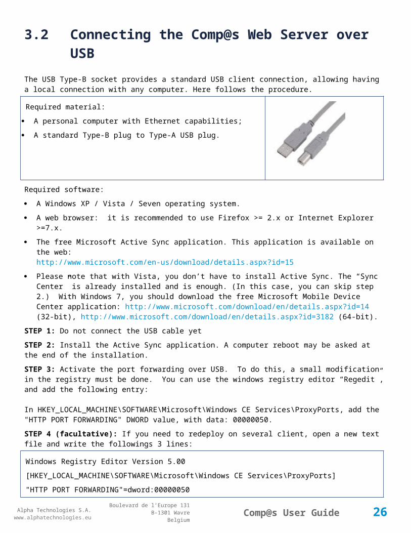
The USB Type-B socket provides a standard USB client connection, allowing having a local connection with any computer. Here follows the procedure.
Required material:
A personal computer with Ethernet capabilities;
A standard Type-B plug to Type-A USB plug.
Required software:
A Windows XP / Vista / Seven operating system.
A web browser: it is recommended to use Firefox >= 2.x or Internet Explorer >=7.x.
The free Microsoft Active Sync application. This application is available on the web:http://www.microsoft.com/en-us/download/details.aspx?id=15
Please note that with Vista, you don’t have to install Active Sync. The “Sync Center” is already installed and is enough. (In this case, you can skip step 2.) With Windows 7, you should download the free Microsoft Mobile Device Center application: http://www.microsoft.com/download/en/details.aspx?id=14 (32-bit), http://www.microsoft.com/download/en/details.aspx?id=3182 (64-bit).
STEP 1: Do not connect the USB cable yet
STEP 2: Install the Active Sync application. A computer reboot may be asked at the end of the installation.
STEP 3: Activate the port forwarding over USB. To do this, a small modification in the registry must be done. You can use the windows registry editor “Regedit”, and add the following entry:
In HKEY_LOCAL_MACHINE\SOFTWARE\Microsoft\Windows CE Services\ProxyPorts, add the "HTTP PORT FORWARDING" DWORD value, with data: 00000050.
STEP 4 (facultative): If you need to redeploy on several client, open a new text file and write the followings 3 lines:
Windows Registry Editor Version 5.00
[HKEY_LOCAL_MACHINE\SOFTWARE\Microsoft\Windows CE Services\ProxyPorts]
"HTTP PORT FORWARDING"=dword:00000050
Then, save the file as “Compas.reg” and execute it (double-click).
STEP 5: Connect the USB cable between the personal computer and the Comp@s monitoring.
STEP 6: Active Sync application should detect the connection and ask to “Set Up a PartnerShip”. Just click on “No” and afterwards on “Next”.
STEP 7: It is now possible to browse the Comp@s Flash disk content by going to: Start menu > Computer > Compas, under Windows Vista or Windows 7 (or: Desktop > My Computer > Mobile Device, under Windows XP).
STEP 8: Start your Web Browser and enter the URL address http://127.0.0.1 or http://localhost .
23
Alpha Technologies S.A.www.alphatechnologies.eu
Alpha Technologies S.A.www.alphatechnologies.eu
Comp@s User GuideBoulevard de l’Europe 131
B-1301 WavreBelgium
STEP 9: The Comp@s web server will ask for a login and a password which are:
Default admin passwordLogin/User Name: adminPassword: compas(Please note that login and password are case sensitive)
You are now connected on the web interface as administrator of the system.
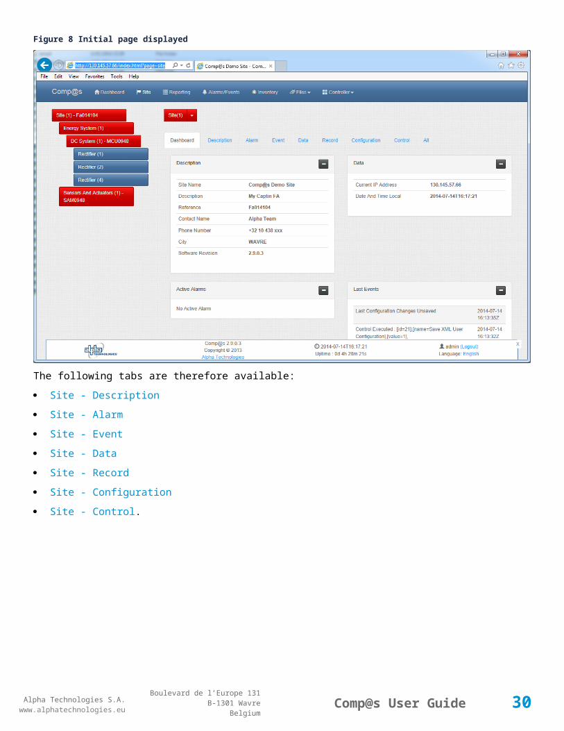
3.3 The Web InterfaceThe following figure shows the default initial web page displayed after login (Site):
The top menu gives access to other pages
The left part shows the hierarchy of the component of the system (Site, DC System, Rectifier, etc.). If all these tree nodes are in a blue color, no alarm is active. Otherwise, red = major alarm, orange = minor, yellow = warning.
The main content concerns the description of a site, comprising address, GPS position, etc. One can see the presence of different tabs (Description, Alarms, Events, Data, Records, Configuration), allowing to see corresponding values related to the selected tree node.
The bottom part displays the date and the time, software information, login information, and language selection
24

Alpha Technologies S.A.www.alphatechnologies.eu
Alpha Technologies S.A.www.alphatechnologies.eu
Comp@s User GuideBoulevard de l’Europe 131
B-1301 WavreBelgium
The website is structured as shown if the following diagram:
25
Alpha Technologies S.A.www.alphatechnologies.eu
Alpha Technologies S.A.www.alphatechnologies.eu
Comp@s User GuideBoulevard de l’Europe 131
B-1301 WavreBelgium
Figure 7 Initial page displayed (Site by default)
3.3.1 SiteThe following figure shows the default initial web page displayed after login (Site):
The top menu gives access to other pages
The left part shows the hierarchy of the component of the system (Site, DC System, Rectifier, etc.). If all these tree nodes are in a blue color, no alarm is active. Otherwise, red = major alarm, orange = minor, yellow = warning.
The main content concerns the description of a site, comprising address, GPS position, etc. One can see the presence of different tabs (Description, Alarms, Events, Data, Records, Configuration), allowing to see corresponding values related to the selected tree node.
The bottom part displays the date and the time, software information, login information, and language selection
26

Alpha Technologies S.A.www.alphatechnologies.eu
Alpha Technologies S.A.www.alphatechnologies.eu
Comp@s User GuideBoulevard de l’Europe 131
B-1301 WavreBelgium
Figure 8 Initial page displayed
The following tabs are therefore available:
Site - Description
Site - Alarm
Site - Event
Site - Data
Site - Record
Site - Configuration
Site - Control.
27

Alpha Technologies S.A.www.alphatechnologies.eu
Alpha Technologies S.A.www.alphatechnologies.eu
Comp@s User GuideBoulevard de l’Europe 131
B-1301 WavreBelgium
3.3.1.1 Site - DashboardFigure 9 Dc system Dashboard
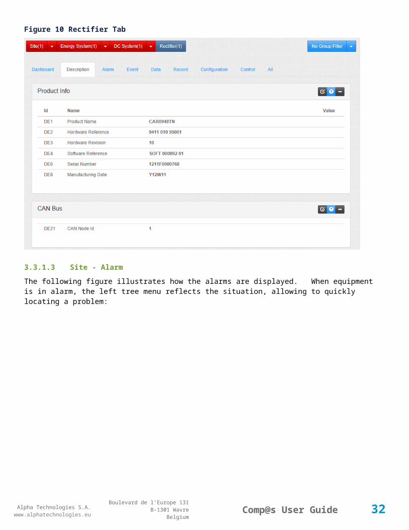
3.3.1.2 Site - DescriptionThe following screenshot shows an automatic description of a specific rectifier. Some of our rectifiers embed their hardware/software reference and revision, their serial number, manufacturing id, manufacturing date, etc. This allows a powerful traceability of our products in a network of widely spread cabinet:
28

Alpha Technologies S.A.www.alphatechnologies.eu
Alpha Technologies S.A.www.alphatechnologies.eu
Comp@s User GuideBoulevard de l’Europe 131
B-1301 WavreBelgium
Figure 10 Rectifier Tab
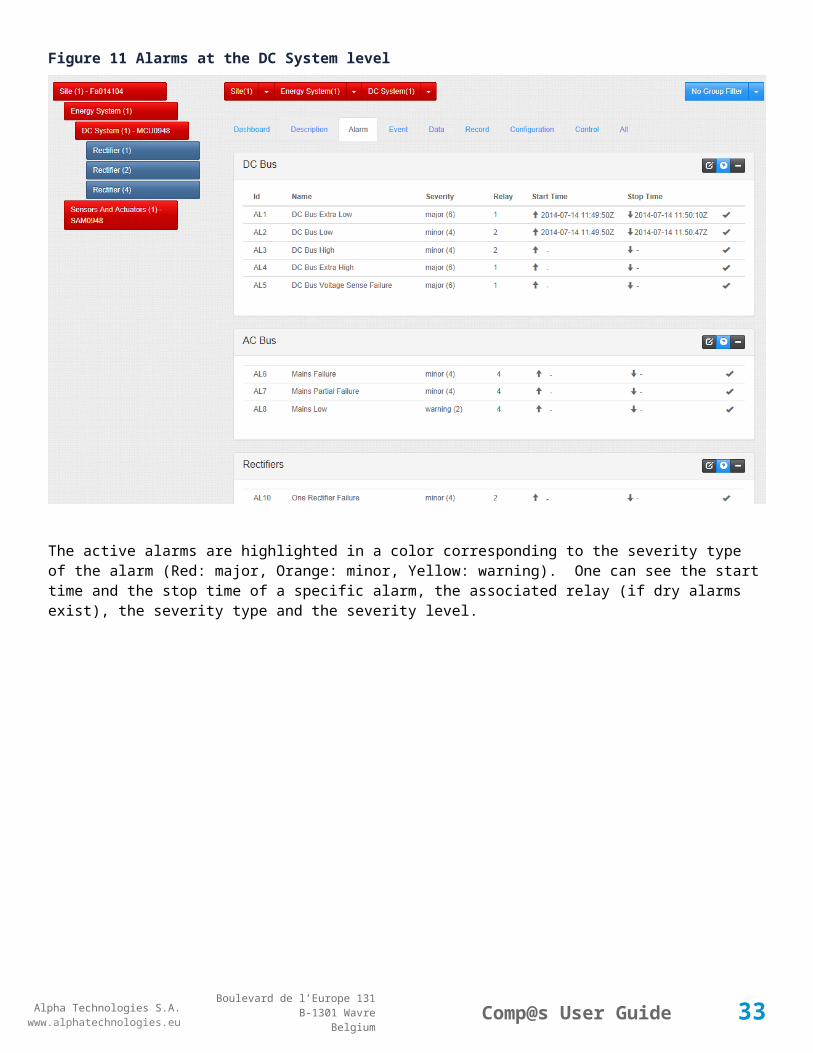
3.3.1.3 Site - AlarmThe following figure illustrates how the alarms are displayed. When equipment is in alarm, the left tree menu reflects the situation, allowing to quickly locating a problem:
29
Alpha Technologies S.A.www.alphatechnologies.eu
Alpha Technologies S.A.www.alphatechnologies.eu
Comp@s User GuideBoulevard de l’Europe 131
B-1301 WavreBelgium
Figure 11 Alarms at the DC System level
The active alarms are highlighted in a color corresponding to the severity type of the alarm (Red: major, Orange: minor, Yellow: warning). One can see the start time and the stop time of a specific alarm, the associated relay (if dry alarms exist), the severity type and the severity level.
30

Alpha Technologies S.A.www.alphatechnologies.eu
Alpha Technologies S.A.www.alphatechnologies.eu
Comp@s User GuideBoulevard de l’Europe 131
B-1301 WavreBelgium
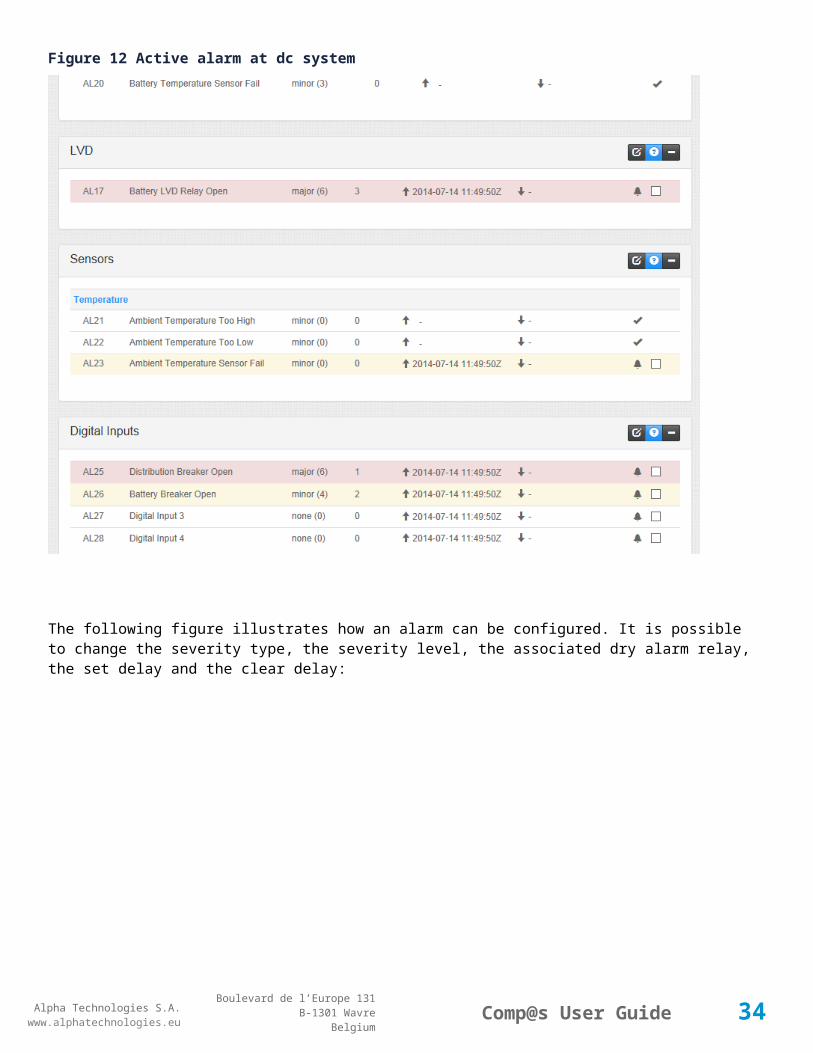
Figure 12 Active alarm at dc system
The following figure illustrates how an alarm can be configured. It is possible to change the severity type, the severity level, the associated dry alarm relay, the set delay and the clear delay:
31
Alpha Technologies S.A.www.alphatechnologies.eu
Alpha Technologies S.A.www.alphatechnologies.eu
Comp@s User GuideBoulevard de l’Europe 131
B-1301 WavreBelgium
Figure 13 Alarm configuration
If you need help, you can display it by clicking on the question mark.
Figure 14 Diplaying Help
32
Alpha Technologies S.A.www.alphatechnologies.eu
Alpha Technologies S.A.www.alphatechnologies.eu
Comp@s User GuideBoulevard de l’Europe 131
B-1301 WavreBelgium
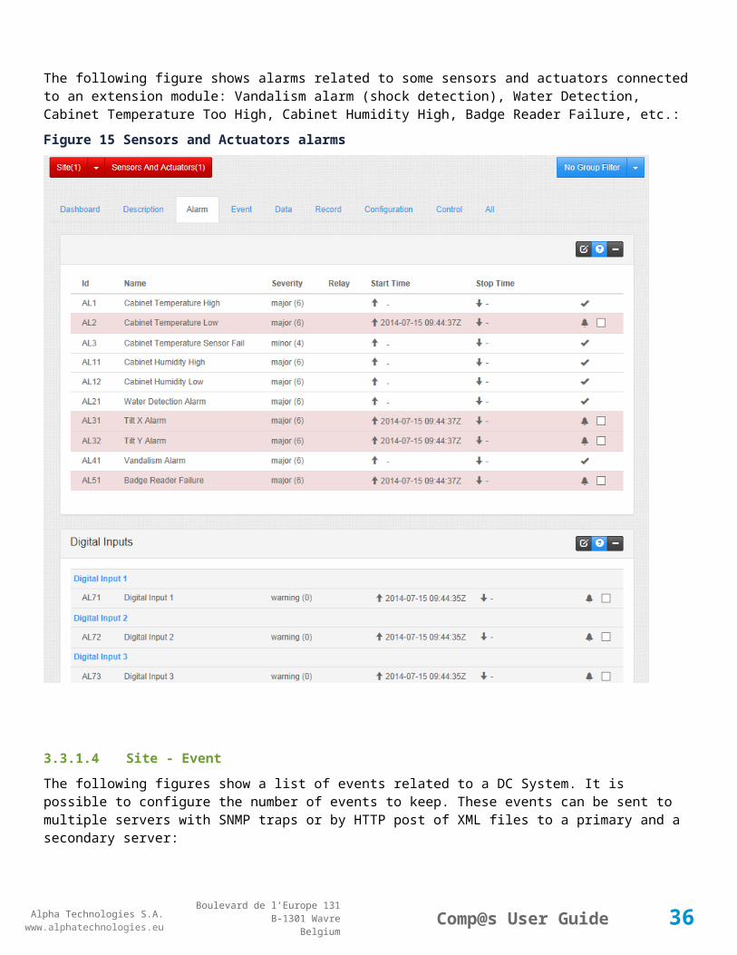
The following figure shows alarms related to some sensors and actuators connected to an extension module: Vandalism alarm (shock detection), Water Detection, Cabinet Temperature Too High, Cabinet Humidity High, Badge Reader Failure, etc.:
Figure 15 Sensors and Actuators alarms
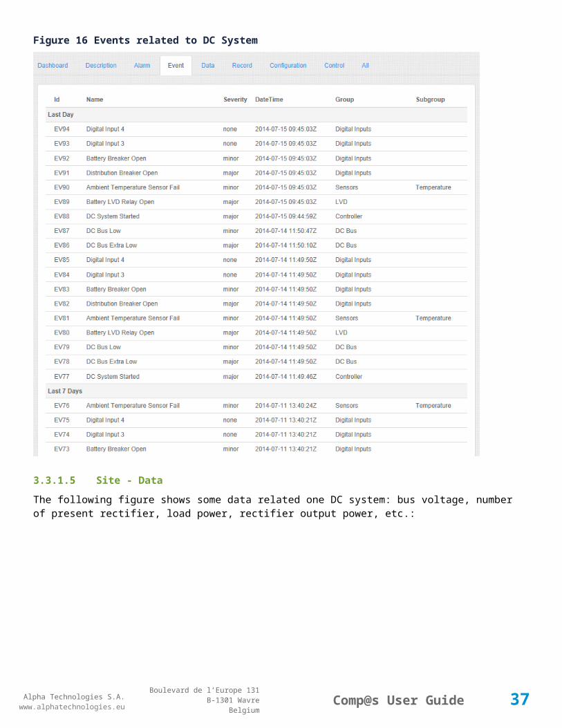
3.3.1.4 Site - EventThe following figures show a list of events related to a DC System. It is possible to configure the number of events to keep. These events can be sent to multiple servers with SNMP traps or by HTTP post of XML files to a primary and a secondary server:
33
Alpha Technologies S.A.www.alphatechnologies.eu
Alpha Technologies S.A.www.alphatechnologies.eu
Comp@s User GuideBoulevard de l’Europe 131
B-1301 WavreBelgium
Figure 16 Events related to DC System
3.3.1.5 Site - DataThe following figure shows some data related one DC system: bus voltage, number of present rectifier, load power, rectifier output power, etc.:
34

Alpha Technologies S.A.www.alphatechnologies.eu
Alpha Technologies S.A.www.alphatechnologies.eu
Comp@s User GuideBoulevard de l’Europe 131
B-1301 WavreBelgium
Figure 17 Data related to DC System
The following screenshot shows detailed data related to a specific rectifier. It is possible to retrieve for example: the power rating, the fan speed, the temperature, the total converted energy, the service time, the input AC voltage, etc. The screenshot is an example for the CAR0948TN rectifier:
35
Alpha Technologies S.A.www.alphatechnologies.eu
Alpha Technologies S.A.www.alphatechnologies.eu
Comp@s User GuideBoulevard de l’Europe 131
B-1301 WavreBelgium
Figure 18 Rectifier Data
The following screenshot shows data related to some sensors and actuators connected to an extension card. One can see the cabinet temperature, the relative humidity, the tilt of a cabinet, heat exchanger status, RFID badge reader information, door lock state, etc.:
36
Alpha Technologies S.A.www.alphatechnologies.eu
Alpha Technologies S.A.www.alphatechnologies.eu
Comp@s User GuideBoulevard de l’Europe 131
B-1301 WavreBelgium
Figure 19 Sensors and Actuators data
3.3.1.6 Site - ConfigurationThe following screenshot illustrates some configuration elements for a dc system. Battery test, boost, partial load disconnection, opening LVD, battery temperature compensation can be configured it these tabs:
37

Alpha Technologies S.A.www.alphatechnologies.eu
Alpha Technologies S.A.www.alphatechnologies.eu
Comp@s User GuideBoulevard de l’Europe 131
B-1301 WavreBelgium
Figure 20 DC System Configuration Tab
The configuration of the site:
38

Alpha Technologies S.A.www.alphatechnologies.eu
Alpha Technologies S.A.www.alphatechnologies.eu
Comp@s User GuideBoulevard de l’Europe 131
B-1301 WavreBelgium
Figure 21 Site Configuration
39

Alpha Technologies S.A.www.alphatechnologies.eu
Alpha Technologies S.A.www.alphatechnologies.eu
Comp@s User GuideBoulevard de l’Europe 131
B-1301 WavreBelgium
Figure 22 The configuration of an extension card
3.3.1.7 Site - RecordThe monitoring can keep data records. It can provide the record of the last seconds, last minutes, last hours, last days, and last months. This is a powerful tool to do statistics and optimize many parameters in your systems.
Note that these records are accessible only if the “asset” license package is present.
40

Alpha Technologies S.A.www.alphatechnologies.eu
Alpha Technologies S.A.www.alphatechnologies.eu
Comp@s User GuideBoulevard de l’Europe 131
B-1301 WavreBelgium
Figure 23 DC System Record Tab
When only one record is selected, for the Minute, Hour and Day resolution, the min and the max is also displayed.
41

Alpha Technologies S.A.www.alphatechnologies.eu
Alpha Technologies S.A.www.alphatechnologies.eu
Comp@s User GuideBoulevard de l’Europe 131
B-1301 WavreBelgium
Figure 24 Bus Voltage record of the last minutes
You can zoom in/out with the wheel mouse and pan with the left click. As the chart is refreshed every 5 second, you can pause this behavior.Figure 25 Zoom and Pan in the chart
The records can be download in CSV format (Coma Separeted Value). The first line is the data name.
42

Alpha Technologies S.A.www.alphatechnologies.eu
Alpha Technologies S.A.www.alphatechnologies.eu
Comp@s User GuideBoulevard de l’Europe 131
B-1301 WavreBelgium
Figure 26 Download in CSV format
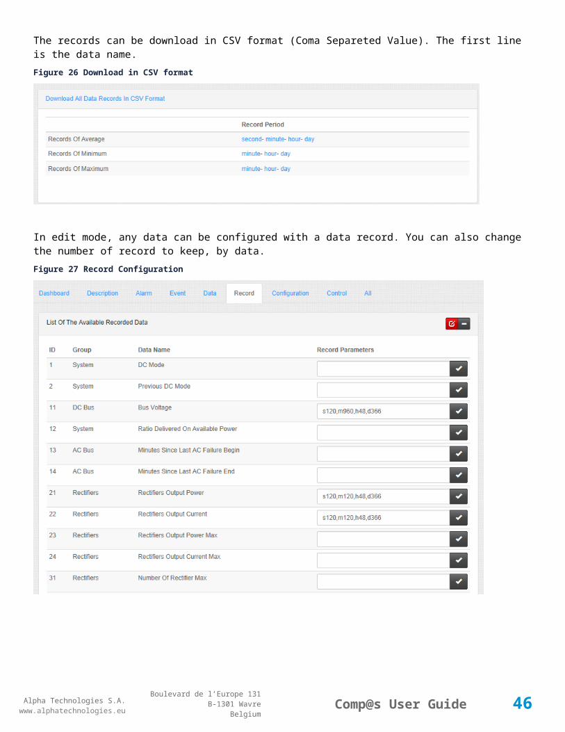
In edit mode, any data can be configured with a data record. You can also change the number of record to keep, by data.Figure 27 Record Configuration
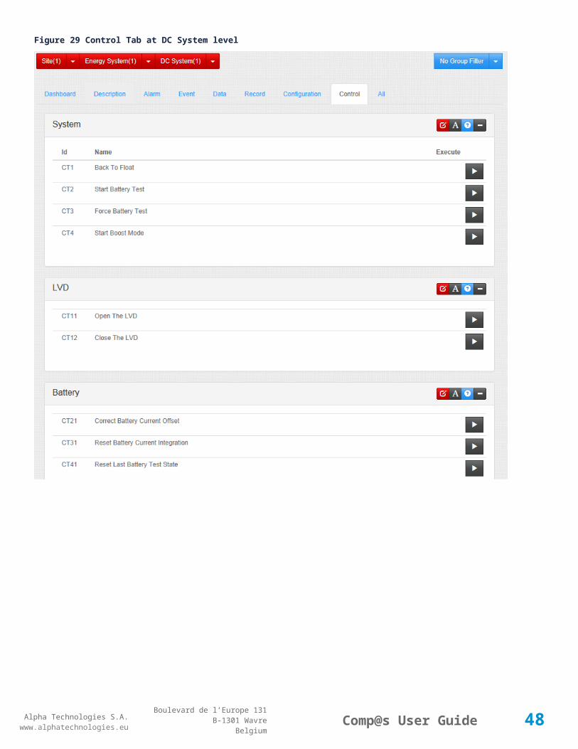
3.3.1.8 Site - ControlA control tab contains elements which can be executed, like starting a battery test, rebooting the monitoring, etc. The control command when the user clicks on the “Execute” button. On some entry, a parameter value is passed when executing the command:
43

Alpha Technologies S.A.www.alphatechnologies.eu
Alpha Technologies S.A.www.alphatechnologies.eu
Comp@s User GuideBoulevard de l’Europe 131
B-1301 WavreBelgium
Figure 28 Control Tab at site level
44

Alpha Technologies S.A.www.alphatechnologies.eu
Alpha Technologies S.A.www.alphatechnologies.eu
Comp@s User GuideBoulevard de l’Europe 131
B-1301 WavreBelgium
Figure 29 Control Tab at DC System level
45
Alpha Technologies S.A.www.alphatechnologies.eu
Alpha Technologies S.A.www.alphatechnologies.eu
Comp@s User GuideBoulevard de l’Europe 131
B-1301 WavreBelgium
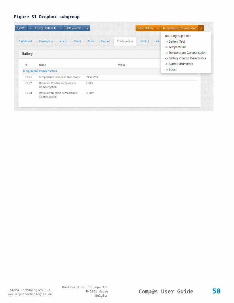
3.3.1.9 Filter Concept - Group/SubgroupFigure 30 Dropbox for grouping
Figure 31 Dropbox subgroup
46

Alpha Technologies S.A.www.alphatechnologies.eu
Alpha Technologies S.A.www.alphatechnologies.eu
Comp@s User GuideBoulevard de l’Europe 131
B-1301 WavreBelgium
3.3.1.10 Site - All
3.3.2 Dashboard
Figure 32 Dashboard
47
Alpha Technologies S.A.www.alphatechnologies.eu
Alpha Technologies S.A.www.alphatechnologies.eu
Comp@s User GuideBoulevard de l’Europe 131
B-1301 WavreBelgium
3.3.3 Reporting
Figure 33 Site Overview
48

Alpha Technologies S.A.www.alphatechnologies.eu
Alpha Technologies S.A.www.alphatechnologies.eu
Comp@s User GuideBoulevard de l’Europe 131
B-1301 WavreBelgium
Figure 34 Data Records
49
Alpha Technologies S.A.www.alphatechnologies.eu
Alpha Technologies S.A.www.alphatechnologies.eu
Comp@s User GuideBoulevard de l’Europe 131
B-1301 WavreBelgium
3.3.4 Alarms/Events
Figure 35 Alarms/Events
3.3.5 Inventory
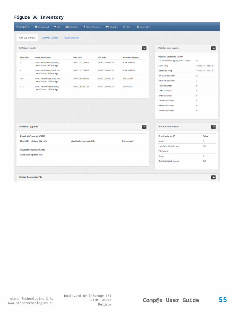
The inventory page is about the device list that Comp@s is managing, over CAN, Ethernet and RS485.
50

Alpha Technologies S.A.www.alphatechnologies.eu
Alpha Technologies S.A.www.alphatechnologies.eu
Comp@s User GuideBoulevard de l’Europe 131
B-1301 WavreBelgium
Figure 36 Inventory
51

Alpha Technologies S.A.www.alphatechnologies.eu
Alpha Technologies S.A.www.alphatechnologies.eu
Comp@s User GuideBoulevard de l’Europe 131
B-1301 WavreBelgium
3.3.6 Files
3.3.7 Controller
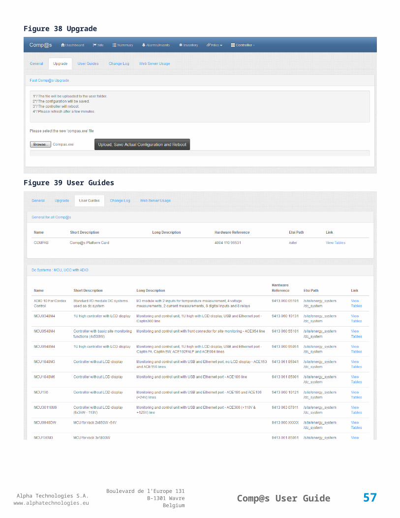
Figure 37 General
52

Alpha Technologies S.A.www.alphatechnologies.eu
Alpha Technologies S.A.www.alphatechnologies.eu
Comp@s User GuideBoulevard de l’Europe 131
B-1301 WavreBelgium
Figure 38 Upgrade
Figure 39 User Guides
53

Alpha Technologies S.A.www.alphatechnologies.eu
Alpha Technologies S.A.www.alphatechnologies.eu
Comp@s User GuideBoulevard de l’Europe 131
B-1301 WavreBelgium
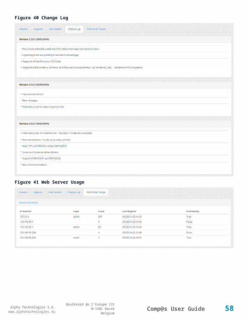
Figure 40 Change Log
Figure 41 Web Server Usage
54
Alpha Technologies S.A.www.alphatechnologies.eu
Alpha Technologies S.A.www.alphatechnologies.eu
Comp@s User GuideBoulevard de l’Europe 131
B-1301 WavreBelgium
Figure 42 Quick Links
3.3.8 Modifying values
The following figures illustrate how to change any configurable value. When you click on the button "Modify", all the configurable values become editable. You are now able to change the value.
55

Alpha Technologies S.A.www.alphatechnologies.eu
Alpha Technologies S.A.www.alphatechnologies.eu
Comp@s User GuideBoulevard de l’Europe 131
B-1301 WavreBelgium
Figure 43 Edit Mode
56
Alpha Technologies S.A.www.alphatechnologies.eu
Alpha Technologies S.A.www.alphatechnologies.eu
Comp@s User GuideBoulevard de l’Europe 131
B-1301 WavreBelgium
Figure 44 Modifying values
A click on the “Validate (V)” button sends the change to the monitoring. This method is used to change any parameter of the system. If the parameter is wrong, a message is displayed or the previous parameter is reset.
Note that each modification of setting must be confirmed individually by a “click” on the “Modify” button of the concerned parameter or information.
If you reboot the system after parameters change, modification will be lost. You have to save the system configuration after changes, as explained in Saving The Changes.
3.3.9 Changing the Network Configuration
Network configuration stepsSTEP 1: Browse to Site --> All, and filter on Network:
The configuration parameters are available in Site -> Configuration. But it is easier to display 'All', filtered with group 'Network' to see live related data and control at the same time. Detailed Information about these parameters is available in the detailed table of chapter 8.1.:
Figure 45 Network configuration
57
Alpha Technologies S.A.www.alphatechnologies.eu
Alpha Technologies S.A.www.alphatechnologies.eu
Comp@s User GuideBoulevard de l’Europe 131
B-1301 WavreBelgium
STEP 2: Switch to edit mode and configure. (Help is available by clicking the '?')
Figure 46 Edit Network Configuration
Note that the changes are not applied immediately! You have to apply the changes …
STEP 3: To apply the changes, use the control CT6 : 'Apply Network Configuration'
58

Alpha Technologies S.A.www.alphatechnologies.eu
Alpha Technologies S.A.www.alphatechnologies.eu
Comp@s User GuideBoulevard de l’Europe 131
B-1301 WavreBelgium
Network configuration stepsSTEP 1: Browse to Site --> All, and filter on Network:
The configuration parameters are available in Site -> Configuration. But it is easier to display 'All', filtered with group 'Network' to see live related data and control at the same time. Detailed Information about these parameters is available in the detailed table of chapter 8.1.:
Figure 47 Network configuration
STEP 2: Switch to edit mode and configure. (Help is available by clicking the '?')
Figure 48 Edit Network Configuration
59

Alpha Technologies S.A.www.alphatechnologies.eu
Alpha Technologies S.A.www.alphatechnologies.eu
Comp@s User GuideBoulevard de l’Europe 131
B-1301 WavreBelgium
Note that the changes are not applied immediately! You have to apply the changes …
STEP 3: To apply the changes, use the control CT6 : 'Apply Network Configuration'
The data DA1 'Current IP Address' should change at that time. If it is empty, it means that there is no network available.
STEP 4: If all is ok, save the configuration to make it permanent. Otherwise, it will be lost after a reboot. (Top Menu: Controller --> Save Configuration).
3.3.10 Saving The ChangesOnce settings have been modified, they must be saved in the persistent Comp@s memory. If not, these modifications will be lost on the next reboot.
2 possibilities : The fast one:In the controller menu, click on 'Save Configuration'.
60

Alpha Technologies S.A.www.alphatechnologies.eu
Alpha Technologies S.A.www.alphatechnologies.eu
Comp@s User GuideBoulevard de l’Europe 131
B-1301 WavreBelgium
The standard one:STEP 1: Click on “Site”
STEP 2: Browse to “Control” (Most right tab)
STEP 3: Click on “Execute” at the entry “Save XML User Configuration” (CT21)
CT20 is used if you removed some equipments and you don't want to keep the configuration for this old equipment.
STEP 4: The settings are now stored in the Comp@s Persistent Memory:
Please refer to Copying configuration from a system to another to load a configuration on a system.
3.3.11 Getting some help about the elements
You can get help at any time by clicking on the '?' button.
61

Alpha Technologies S.A.www.alphatechnologies.eu
Alpha Technologies S.A.www.alphatechnologies.eu
Comp@s User GuideBoulevard de l’Europe 131
B-1301 WavreBelgium
Figure 49 Element Help
The same behavior in edit mode :
62

Alpha Technologies S.A.www.alphatechnologies.eu
Alpha Technologies S.A.www.alphatechnologies.eu
Comp@s User GuideBoulevard de l’Europe 131
B-1301 WavreBelgium
Figure 50 Edit Mode with Help
3.4 The Comp@s SNMP Agent
The Simple Network Management Protocol (SNMP) exposes management data in the form of variables on the managed systems, which describe the system configuration. These variables can then be queried and sometimes set by managing applications.
The Comp@s monitoring provides a SNMP v1, v2c and V3 interface.
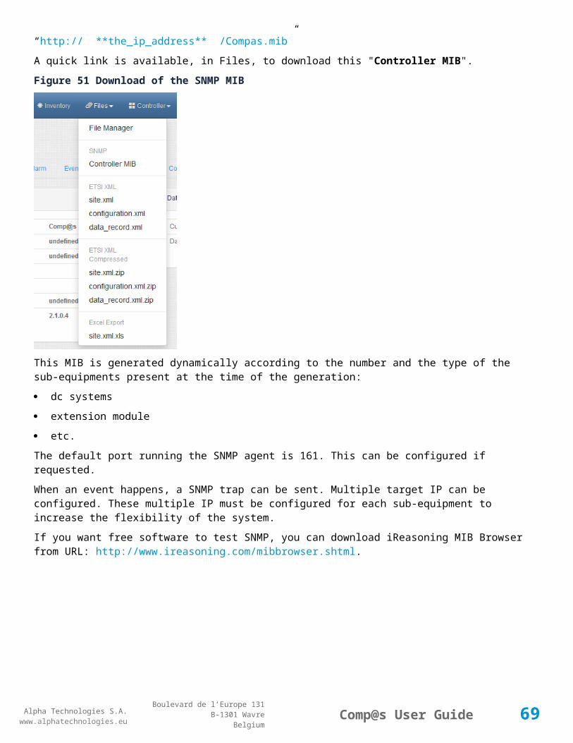
The Management Information Base (MIB) can be downloaded at the url:
“http:// **the_ip_address** /Compas.mib”
63

Alpha Technologies S.A.www.alphatechnologies.eu
Alpha Technologies S.A.www.alphatechnologies.eu
Comp@s User GuideBoulevard de l’Europe 131
B-1301 WavreBelgium
A quick link is available, in Files, to download this "Controller MIB".
Figure 51 Download of the SNMP MIB
This MIB is generated dynamically according to the number and the type of the sub-equipments present at the time of the generation:
dc systems
extension module
etc.
The default port running the SNMP agent is 161. This can be configured if requested.
When an event happens, a SNMP trap can be sent. Multiple target IP can be configured. These multiple IP must be configured for each sub-equipment to increase the flexibility of the system.
If you want free software to test SNMP, you can download iReasoning MIB Browser from URL: http://www.ireasoning.com/mibbrowser.shtml.
64

Alpha Technologies S.A.www.alphatechnologies.eu
Alpha Technologies S.A.www.alphatechnologies.eu
Comp@s User GuideBoulevard de l’Europe 131
B-1301 WavreBelgium
Figure 52 Ireasoning MIB Browser
The SNMP agent supports the SNMP v1, v2c and V3 command:
GET
SET
WALK
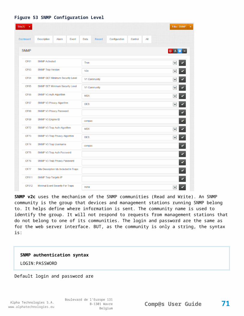
The SNMP configuration is available at the site -> configuration level, as shown on the following screenshot:
65

Alpha Technologies S.A.www.alphatechnologies.eu
Alpha Technologies S.A.www.alphatechnologies.eu
Comp@s User GuideBoulevard de l’Europe 131
B-1301 WavreBelgium
Figure 53 SNMP Configuration Level
SNMP v2c uses the mechanism of the SNMP communities (Read and Write). An SNMP community is the group that devices and management stations running SNMP belong to. It helps define where information is sent. The community name is used to identify the group. It will not respond to requests from management stations that do not belong to one of its communities. The login and password are the same as for the web server interface. BUT, as the community is only a string, the syntax is:
SNMP authentication syntaxLOGIN:PASSWORD
Default login and password are
SNMP default login and passwordRead Community -> admin:compas
Write Community -> admin:compas
66

Alpha Technologies S.A.www.alphatechnologies.eu
Alpha Technologies S.A.www.alphatechnologies.eu
Comp@s User GuideBoulevard de l’Europe 131
B-1301 WavreBelgium
SNMP V3 uses login and passwords. The same accounts are used as in the web interface.
You can define a minimum security level (an SNMP version) for SET and GET operations:
No Authentication
V1 Community
V2c Community
V3
If you are using SNMP V3, you can set an Auth Algorithm:
MD5 : Message Digest Algorithm 5 – HMAC-MD5-96
SHA : Secure Hash Algorithm – HMAC-SHA-96
Any: Both MD5 and SHA will be tried.
You can also use privacy password with a privacy Algorithm:
DES: Data Encryption Standard
AES: Advanced Encryption Standard with key length of 128
3DES: Triple Data Encryption Standard.
67

Alpha Technologies S.A.www.alphatechnologies.eu
Alpha Technologies S.A.www.alphatechnologies.eu
Comp@s User GuideBoulevard de l’Europe 131
B-1301 WavreBelgium
4 F U N C T I O N A L I T I E S
User Access Management
Save / Load configuration
Automatic events saving
Date and Time Management
Software Upgrade Management
Reset Factory Settings
Copying configuration from a system to another
PLC Functionalities
Translating The Web Interface
Replacing a Rectifier in a DC System
Measuring Power and Energy.
4.1 User Access Management
The web server and the SNMP agent are protected by an authentication mechanism based on login/password.
There are by default six users defined: one administrator and 5 users:
Login Password
admin compas
user1 compas
user2 compas
user3 compas
user4 compas
user5 compas
All these default login/password can be changed by the help of any interface. The passwords are encrypted in the configuration file, the key also relies on the user name. These parameters are located in Site -> Configuration, as shown on the following figure:
68
Alpha Technologies S.A.www.alphatechnologies.eu
Alpha Technologies S.A.www.alphatechnologies.eu
Comp@s User GuideBoulevard de l’Europe 131
B-1301 WavreBelgium
Figure 54 Users login and password configuration
The administrator is allowed to use all the functionalities of the monitoring and to change any configuration parameter.
The 5 users can only access the functionalities they are authorized to. It is possible to define, for each equipment of the site hierarchy, which user has read access and which user has write access. The following figure shows the “Read Access User Numbers” and the “Write Access User Numbers” configuration entries. The value is a list of coma separated values corresponding to the user number allowed to read or write at the Site level. These 2 parameters are also available in each “DC system” and in each “Sensors and Actuators”.
Please remark that the users which have write access at the Site level are able to change the login and the password of all the other users, including the administrator.
The procedure to change the login and password of a user is:
STEP 1: Browse to Site ->Configuration
STEP 2: Click on “Edit Mode”
STEP 3: Enter the new login and password in clear for the desired user id. The syntax is:
Login and passwordLOGIN:PASSWORD -> mike:mypassword
Figure 55 User login and password change screen
STEP 4: Click on “Validate” button. The password is immediately encrypted and the page is refreshed:
Figure 56 User new login and password change screen
69

Alpha Technologies S.A.www.alphatechnologies.eu
Alpha Technologies S.A.www.alphatechnologies.eu
Comp@s User GuideBoulevard de l’Europe 131
B-1301 WavreBelgium
STEP 5: Do not forget to save the configuration.
4.2 Save / Load configuration
See Saving The Changes.
Please refer to Copying configuration from a system to another to load a configuration on a system.
4.3 Automatic events saving
The system is configured to keep all the events in case of power failure of the monitoring. It is automatically appending the events to a flat file: "events_flat.xml", in the user folder.
4.4 Date and Time Management
Figure 57 Date And Time Configuration
Real Time Clock
Time zone and Daylight Saving Time
(S)NTP Time Protocol.
4.4.1 Real Time Clock
The monitoring embeds a real time clock in order to manage the event time, periodic actions, etc.
You can change the local or the UTC time in Site -> Control. (CT12 / CT13)
70
Alpha Technologies S.A.www.alphatechnologies.eu
Alpha Technologies S.A.www.alphatechnologies.eu
Comp@s User GuideBoulevard de l’Europe 131
B-1301 WavreBelgium
4.4.2 Time zone and Daylight Saving Time
You can configure the time zone in Site -> Configuration (CF14).
In edit mode, you will see all the available timezone in the drop down list.
Figure 58 List of Available Timezones
All the available time zone can aslo be retrieved at URL: (For API usage)
Available time zonehttp://the_ip/timezones.txt
Here follows a screenshot of a part of this list:
71

Alpha Technologies S.A.www.alphatechnologies.eu
Alpha Technologies S.A.www.alphatechnologies.eu
Comp@s User GuideBoulevard de l’Europe 131
B-1301 WavreBelgium
Figure 59 Partial Time Zone List
The daylight saving time is activated on the monitoring, the summer and winter time will be automatically adjusted according to the selected time zone.
Note: When a change in time zone has been done, it is necessary to reboot the monitoring to have the changes applied.
4.4.3 (S)NTP Time ProtocolThe time can be automatically synchronized with an UTC time server, implementing the Network Time Protocol (NTP) protocol (or SNTP). This allows having all the monitoring time synchronized with one reference time server.
The configuration parameters are available at Site -> Configuration, as shown above (Time zone and Daylight Saving Time).
You can configure SNTP Time Server with an IP address or with a domain (if the DNS is set correctly - swisstime.ethz.ch, for example).
The time is retrieved automatically when the system boot and every week. If it fails, it will automatically retry the next day.
You can force an SNTP time refresh in Site -> Control, as shown above (Real Time Clock).
4.5 Software Upgrade Management
Upgrading the Comp@s Software
Upgrading a Firmware with Comp@s.
4.5.1 Upgrading the Comp@s Software
Checking Comp@s revision
Upgrading Locally with USB
Upgrading Remotely with Ethernet
4.5.1.1 Checking Comp@s revisionYou can check the running Comp@s software version in Site -> Data -> Software Revision:
72

Alpha Technologies S.A.www.alphatechnologies.eu
Alpha Technologies S.A.www.alphatechnologies.eu
Comp@s User GuideBoulevard de l’Europe 131
B-1301 WavreBelgium
Figure 60 Software Revision
It is also displayed at the bottom of all the web pages:
Figure 61 Software Revision at bottom of web pages
To update the Comp@s software, two possibilities are available:
Upgrading remotely with Ethernet
Upgrading locally with USB.
4.5.1.2 Upgrading Locally with USBThe upgrade is done trough the USB Active Sync connection.
STEP 1: Be sure you have ActiveSync correctly installed as described in (Getting Started – Connecting with USB).
STEP 2: Connect the USB cable between the Comp@s system and your personal computer.
STEP 3: Open the windows explorer and click on “Mobile Device”, under “My Computer”. You should have access to the memory of the Comp@s Monitoring.
STEP 4: Browse to “\\FlashDisk\User” (“\\NOR Flash\\User” on some previous release):
73

Alpha Technologies S.A.www.alphatechnologies.eu
Alpha Technologies S.A.www.alphatechnologies.eu
Comp@s User GuideBoulevard de l’Europe 131
B-1301 WavreBelgium
Figure 62 Browse to “\FlashDiskUser”
STEP 5: Copy the new “Compas.exe” release in that folder.
STEP 6: Reboot the monitoring with the Web Interface.
STEP 7: You can check that the running software revision has changed.
4.5.1.3 Upgrading Remotely with Ethernet Upgrading with FTP
Upgrading with Web Interface
Upgrading with FTPThe upgrade is done trough FTP connection:
Upgrading Comp@s remotely with FTPSTEP 1: Connect the system with your FTP client (See ”Connecting the Comp@s FTP Server”).
STEP 2: Browse to the “\user” folder, in the “\\FlashDisk” folder (“\\NOR Flash” on previous software release):
Figure 63 FTP Connection with Filezilla
74

Alpha Technologies S.A.www.alphatechnologies.eu
Alpha Technologies S.A.www.alphatechnologies.eu
Comp@s User GuideBoulevard de l’Europe 131
B-1301 WavreBelgium
STEP 3: Copy the new “Compas.exe” release in that folder.
STEP 4: Reboot the monitoring with the Web Interface (Site -> Control) or with SNMP.
STEP 5: You can check that the running software revision has changed.
Upgrading with Web InterfaceThere is two possibilities to upgrade with the web interface. A very automated one and a manual.
Fast Comp@s Upgrade (recommended)Click on Controller --> Upgrade.
Figure 64 Controller-Upgrade
Follow the instruction:
Please select the new 'compas.exe' or compas*.zip file on your computer and click the Button 'Upload, Save Actual Configuration and Reboot'.
The automated process will:
If zip: Extract the file (and validate the compas.exe.md5 checksum if available in the zip file)
move the Compas.exe to the user folder.
Save the configuration
Reboot the Controller
After less than 2 minutes, the controller is fully operational.
75

Alpha Technologies S.A.www.alphatechnologies.eu
Alpha Technologies S.A.www.alphatechnologies.eu
Comp@s User GuideBoulevard de l’Europe 131
B-1301 WavreBelgium
Figure 65 Fast Comp@s Upgrade
Manual Comp@s UpradeThe upgrade is done by using the File Manager : "Files" > "File Manager"
Upgrading Comp@s remotely with HTTP POSTSTEP 1: Go to "File Upload to user-upload Folder". Click "Browse" and select the file to upload to FlashDisk\\user\\upload folder. (If you have a small bandwidth and the file size is large, it can be smart to zip it first.)
Figure 66 Comp@s Manage Files Page
STEP 2: Press "Upload" to upload the file. A message "COMMAND_EXECUTED" (or "COMMAND ERROR") is displayed. The page is then automatically refresh.
STEP 3: The file appears in "List of Files in user-upload Folder". You can select "Extract File" to uncompress a zip archive, then press "Delete" to erase it from folder. (if Zipped)
STEP 4: Press "Replace/Move Compas.exe to user Folder" to move the new compas.exe file to FlashDisk\\user folder.
STEP 5: Use the top bar to Save Configuration and Reboot : Controller --> 'Save Configuration and Reboot'
76

Alpha Technologies S.A.www.alphatechnologies.eu
Alpha Technologies S.A.www.alphatechnologies.eu
Comp@s User GuideBoulevard de l’Europe 131
B-1301 WavreBelgium
4.5.2 Upgrading a Firmware with Comp@sAny software/firmware of any Alpha Technologies equipment connected to the CAN bus can be upgraded remotely thanks to Comp@s.
WARNING: DO NOT POWER OFF THE EQUIPMENT DURING THE PROCEDURE.
STEP 1: You must first upload the firmware ‘SOFT_XXXXX_XX.txt’ or *.acan file on the comp@s card.
The following screen shots shows the Inventory web page :
It will upload the file directly to the correct path : “\\FlashDisk\User\Firmware”.
This upload can also be done through FTP or USB.
The following screenshot shows the folder with one file, in a Windows Vista environment:
77
Alpha Technologies S.A.www.alphatechnologies.eu
Alpha Technologies S.A.www.alphatechnologies.eu
Comp@s User GuideBoulevard de l’Europe 131
B-1301 WavreBelgium
Figure 67 Firmware selection
STEP 2: On the inventory page, there is a section with the available upgrade, related to the uploaded files.
Figure 68 Comp@s web page Advanced link
STEP 3: You can upgrade only one node at the time, or all the compatible devices.
78
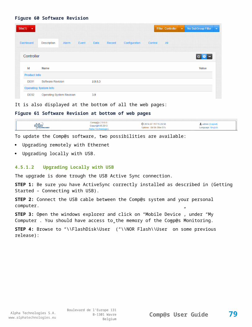
Alpha Technologies S.A.www.alphatechnologies.eu
Alpha Technologies S.A.www.alphatechnologies.eu
Comp@s User GuideBoulevard de l’Europe 131
B-1301 WavreBelgium
Figure 69 File decoding
STEP 4: Once you received the message “COMMAND_EXECUTING”, click ‘OK’. After, you can see the progress in 'Can Bus Information'. The Comp@s card is sending the firmware to the device over the CAN Bus (about 2-3 minutes). Your equipment will disappear from the CANopen Nodes list during the upgrade:
Figure 70 Equipment disappearing during upgrade
STEP 5: When the progression is finished, the equipment reboot and is detected again by Comp@s. The new firmware is installed. You can see the firmware revisions in the “CANOpen Nodes” section (CAN Bus Nodes – SW 12NC).
Note: From version 2.10.0.4, events are generated to trace all the changes done about firmware.
4.5.3 Upgrading The Operating System
The operating system on which Comp@s is running (Windows CE) can be updated. The operating system is not evolving quickly. Last version is 3.9. You can check you version in Site/Description : "Operating System Revision"
WARNING: DO NOT POWER OFF THE EQUIPMENT DURING THE PROCEDURE.
STEP 1: You must first upload the files "COMPAS_EBOOT_xxx.bin" and "COMPAS_OS_xxx.bin" to the the comp@s card. The correct folder is “\\FlashDisk\User\Firmware”. This can be done through FTP or USB. The following screenshot shows the folder inf Filezilla, with both files uploaded.
79

Alpha Technologies S.A.www.alphatechnologies.eu
Alpha Technologies S.A.www.alphatechnologies.eu
Comp@s User GuideBoulevard de l’Europe 131
B-1301 WavreBelgium
Figure 71 Upload files
STEP 2: Go to site/control (CT103), and type the file name to flash.
Figure 72 Flash Binary
STEP 3: You should start to update the EBOOT file (the bootloader), and than the OS. You can follow the progress with the events.
80
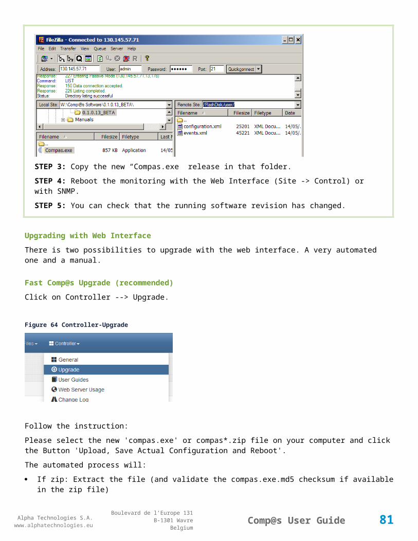
Alpha Technologies S.A.www.alphatechnologies.eu
Alpha Technologies S.A.www.alphatechnologies.eu
Comp@s User GuideBoulevard de l’Europe 131
B-1301 WavreBelgium
Figure 73 Check Site events
STEP 4: Reboot the controller
4.6 Reset Factory Settings
It is possible to easily restore all the settings and software installed in our factory. To do this, delete all the files and folders present is the “\\FlashDisk\User” folder. At next reboot, your monitoring is like the first time you get it.
81

Alpha Technologies S.A.www.alphatechnologies.eu
Alpha Technologies S.A.www.alphatechnologies.eu
Comp@s User GuideBoulevard de l’Europe 131
B-1301 WavreBelgium
4.7 Copying configuration from a system to another
STEP 1: Retrieve the configuration of one system. On the web interface, click on “configuration.xml” and save the file as “configuration.xml”.
STEP 2: Copy this file (configuration.xml) on the other system, in the “user” folder, with FTP over Ethernet, or locally with ActiveSync over USB.
STEP 3: Reboot this other system, the same configuration is applied.
You copy also the network configuration, including the IP address. Keep in mind that if two systems with the same IP address are present on same network, it will not work! A solution to this is to edit the XML file before copying it and to change the IP address.
NoteIf you want to deploy a configuration as the default configuration for your network, you can put the file in the folder “factory”. This file can be renamed like XXX_configuration.xml where XXX is free and of any length. This way you can indicate in the file the type of configuration. Make sure to delete the “configuration.xml” in the “user” folder as this last has the priority. Here follows a diagram for better understanding:
Figure 74 Workflow of the load configuration function
82

Alpha Technologies S.A.www.alphatechnologies.eu
Alpha Technologies S.A.www.alphatechnologies.eu
Comp@s User GuideBoulevard de l’Europe 131
B-1301 WavreBelgium
4.8 PLC FunctionalitiesPLC stands for Programmable Logic Controller. It allows to add custom features by using some logical expression. It is very cost effective for regulation where the main loop is not smaller than 1 sec.
Some configuration elements can be filled with a Boolean expression or a mathematical expression. Here follow information about the syntax and some examples of valid expressions:
Syntax
Examples of Boolean Conditions
Examples of Mathematical Expressions
PLC License Package.
4.8.1 Syntax
Using Data Entries
Using Alarm Entries
Operators
Time Variables
Other Functions.
4.8.1.1 Using Data Entries
Syntax Signification
@(dataXXX) The data with id XXX of the relative equipment
@(dcY_dataXXX) The data with id XXX relative to the dc system with id Y.
Example: @(dc1_data11) is the bus voltage of the DC System 1.
@(saY_dataXXX) The data with id XXX relative to the Sensors And Actuators with id Y.
4.8.1.2 Using Alarm Entries
Syntax Signification
@(alarmXXX) The data with id XXX of the relative equipment
@(dcY_alarmXXX) The data with id XXX relative to the dc system with id Y.
Example: @(dc1_data11) is the bus voltage of the DC System 1.
@(saY_alarmXXX) The data with id XXX relative to the Sensors And Actuators with id Y.
@(severity_level) The severity level of the relative equipment (0->9). This can be useful to activate a relay based on the severity level.
83

Alpha Technologies S.A.www.alphatechnologies.eu
Alpha Technologies S.A.www.alphatechnologies.eu
Comp@s User GuideBoulevard de l’Europe 131
B-1301 WavreBelgium
Syntax Signification
@(dcY_ severity_level)
The severity level relative to the dc system with id Y.
@(saY_severity_level) The severity level relative to the Sensors And Actuators with id Y.
4.8.1.3 Operators
Syntax Signification
( … ) Parentheses
&& Logical AND
|| Logical OR
== Equal
!= Not Equal
+ Addition
- Subtraction
* Multiplication
/ Division
% Modulo
4.8.1.4 Time Variables
Syntax Signification
$second() Second part of the actual time
$minute() Minute part of the actual time
$hour() Hour part of the actual time
$day() Integer indicating the day of the month.
$dayofweek()
Integer indicating the day of the week. This integer ranges from zero, indicating Sunday, to six, indicating Saturday
$dayofyear() Integer indicating the day of the year.
$month() Integer indicating the month of the year.
$year() Integer indicating the year.
$time() The time of the day
84

Alpha Technologies S.A.www.alphatechnologies.eu
Alpha Technologies S.A.www.alphatechnologies.eu
Comp@s User GuideBoulevard de l’Europe 131
B-1301 WavreBelgium
Syntax Signification
@ts(XXXXX) Create a time span variable from XXXX string. Example: @ts(11:32) corresponds to 11h32.
4.8.1.5 Other Functions
Syntax Signification
$abs(XXX) The absolute value of XXX
$sqrt(XXX) The square root value of XXX
$ceil(XXX) The ceil value of XXX
$floor(XXX) The floor value of XXX
$max(X1, X2, X3, …) The maximum value between X1,X2,X3, etc.
$min(X1, X2, X3, …) The minimum value between X1,X2,X3, etc.
$canid(XXX) Can Id XXX is present
$iif(condition, val if true, val if false) Equivalent to "If then else"
$case(condition, val, condition2, val2, ...) Equivalent to "switch"
4.8.2 Examples of Boolean Conditions
Tested Condition Configuration Element Value
The bus voltage is under 47V @(data11)<47
The rectifier output power is over 2500W @(data21)>2500
The time of the day is comprised between 10:23 and 11:34 ($time()>@ts(10:23))&&($time()<@ts(11:34))
The day of the week is sunday $dayofweek()==0
The alarm with id 17 is active @(alarm17) ==True
The alarm with id 17 and 18 are active @(alarm17) ==True && @(alarm18) ==True
true 5 seconds over 10 $second()%10<5
4.8.3 Examples of Mathematical Expressions
Wanted calculation Configuration Element Value
Voltage on bloc 2 of the battery @(data161)-@(data162)
85
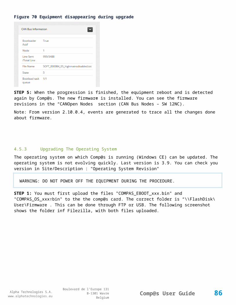
Alpha Technologies S.A.www.alphatechnologies.eu
Alpha Technologies S.A.www.alphatechnologies.eu
Comp@s User GuideBoulevard de l’Europe 131
B-1301 WavreBelgium
4.8.4 PLC License PackageWith the PLC License activated, you are able to add custom data and custom alarms. In Site, DC System and “Sensors and Actuators”, in the configuration tab, the following parameters are available:Figure 75 PLC Number
By default, “Number of PLC Data” and “Number of PLC Alarm” is set to 0. If you increase these numbers, you can access new configuration entries in the same tab:Figure 76 New configuration entries
86
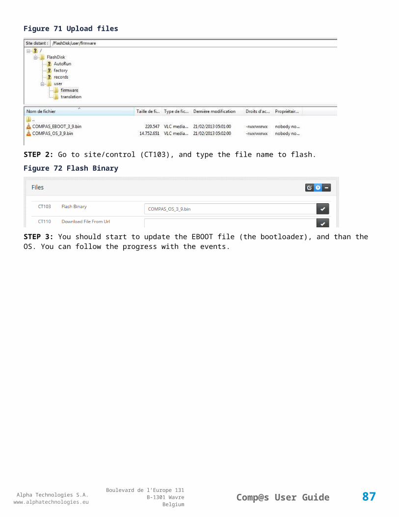
Alpha Technologies S.A.www.alphatechnologies.eu
Alpha Technologies S.A.www.alphatechnologies.eu
Comp@s User GuideBoulevard de l’Europe 131
B-1301 WavreBelgium
You are now able to enter new Boolean expression for the alarms and new Mathematical expression for the data.
These changes are reflected in the data tab and in the alarm tab.
4.9 Translating The Web InterfaceIt is possible to translate the Comp@s Web Interface to satisfy your needs. Here follows the steps:
STEP 1: An empty CSV file with the list of the words and sentences used in the Comp@s interface is available at URL: http://the_compas_ip/translation.csv
STEP 2: This file is encoded in UTF8. After the coma of each line, you can put the wanted translation.
STEP 3: The first two lines are:
CSV file:#LANGUAGE;MYLANGUAGE
#LANG;MYLANG
STEP 4: Replace "MYLANGUAGE" by the equivalent of "ENGLISH".
STEP 5: Replace "MYLANG" by the equivalent of "EN".
STEP 6: Then, save the file (in UTF8!)? You can choose the name you want, but the extension must be "csv".
STEP 7: Copy it to the monitoring with an FTP client to the folder: “/FlashDisk/user/translation/“
RemarkExcel 2003 is not able to save in CSV UTF8. You can use the free "OpenOffice Calc" to do it. Alternatively, you can use any UTF8-capable text editor like SciTE, Notepad2 or Notepad++.
RemarkThe coma separator is ";" and there is no text delimiter
STEP 8: Browsing to Site -> Control.
STEP 9: Reload the Translations as shown on the following figure:
87

Alpha Technologies S.A.www.alphatechnologies.eu
Alpha Technologies S.A.www.alphatechnologies.eu
Comp@s User GuideBoulevard de l’Europe 131
B-1301 WavreBelgium
Figure 77 Reload Translations
4.10 Replacing a Rectifier in a DC System
When pulling out one of the rectifiers from a DC System shelf, it is mandatory to wait a minimum time delay in order that Comp@s detect the removal the CAN Open node. You can check that it was removed in the "Inventory" menu.
The delay is usually around 15-20 seconds.
After CAN Open node was removed from the "Advanced" menu, it is possible to insert another rectifier into the DC System shelf. This one will be automatically detected.
4.11 Measuring Power and Energy
By connecting devices like Schneider PM9C ([1]) or IEM3150 ([2]), it is possible to integrate power and energy metering features into Comp@s.
By default, those devices connect to RS-485 Modbus port, that is present on some Alpha Technologies products.
To configure Comp@s, add for instance the following line to parameter 210 (RS485 Extensions configuration) in Site > Configuration (fields separated by semicolons):
RS485 Extensions configurationPM9C(1);IEM3150(2)
Figure 78 Configure Power and Energy Meter
88

Alpha Technologies S.A.www.alphatechnologies.eu
Alpha Technologies S.A.www.alphatechnologies.eu
Comp@s User GuideBoulevard de l’Europe 131
B-1301 WavreBelgium
In example above, PM9C device with address 1 is added. Also is added IEM3150 with adress 2. Only addresses from 1 to 10 are currently authorized. The devices will be displayed in Comp@s in the same order as in configuration parameter (in example above: 1, 2).
The measurement devices must be configured with following serial communication parameters:
Baudrade: 9600
Data bits: 8
Parity: Odd
Stop bits: 1.
Once added, new equipments 'Energy Meter' are created in the site structure:
89
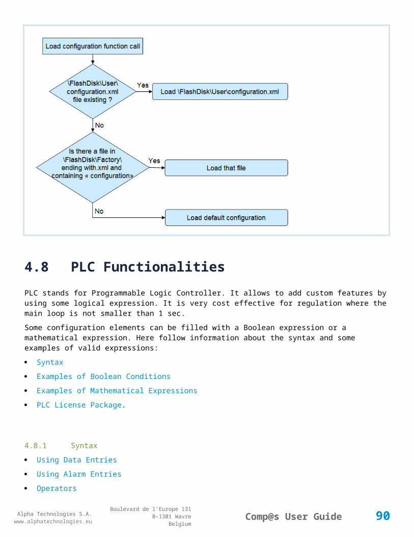
Alpha Technologies S.A.www.alphatechnologies.eu
Alpha Technologies S.A.www.alphatechnologies.eu
Comp@s User GuideBoulevard de l’Europe 131
B-1301 WavreBelgium
If 3-phase current is used instead of single-phase, supplementary data will be displayed. In case of IEM3150, device configuration (single-phase, 3-phase) is displayed in Energy System > Description. It is also possible to record data by navigating to Energy System > Records.
[1] http://www.schneider-electric.com/search/ww/en/relevance/10_1/Product%20Information;;68c72df3-e11c-4867-b873-73310c776a59/all?search_text=pm9c&search_type=new&filters=txt_by_category;;CAT_PRD_DATA
[2] http://www.downloads.schneider-electric.com/sites/oreo/ww/document-detail.page?p_docId=18054169&p_Conf=i#http://www.downloads.schneider-electric.com.
4.12 Mobile Compliant
The new Comp@s 2.0. web interface has been designed to support mobile devices like smartphone and tablets.
Table 1 Mobile Compliant
Tested on Android, Iphone, Ipad and Windows Phone.
The content is automatically resized, and the left menu of the site disappears.
A dynamic menu replaces the top menu bar.
90

Alpha Technologies S.A.www.alphatechnologies.eu
Alpha Technologies S.A.www.alphatechnologies.eu
Comp@s User GuideBoulevard de l’Europe 131
B-1301 WavreBelgium
Figure 79 Dashboard Mobile
4.13 Alarm AcknowledgementWhen an alarm is set, it is possible to acknowledge it. The alarm will stay active, but with an acknowledged status. When the alarm is clear, the status state disappears.
It can be used with Arm@da to differentiate the new alarms and the alarms under investigation by a technician.
When someone acknowledges, an event is generated, with the information about the user and the ip address from which it was done.
91

Alpha Technologies S.A.www.alphatechnologies.eu
Alpha Technologies S.A.www.alphatechnologies.eu
Comp@s User GuideBoulevard de l’Europe 131
B-1301 WavreBelgium
Figure 80 Acknowledgement in Alarms/Events
4.14 EmailComp@s can be configured to send email to one or multiple addresses when a event with a minimal severity happens. A correctly configured SMTP server is required.Figure 81 Email Configuration
Here follows an example of mail :
92

Alpha Technologies S.A.www.alphatechnologies.eu
Alpha Technologies S.A.www.alphatechnologies.eu
Comp@s User GuideBoulevard de l’Europe 131
B-1301 WavreBelgium
Figure 82 Email Sample
93

Alpha Technologies S.A.www.alphatechnologies.eu
Alpha Technologies S.A.www.alphatechnologies.eu
Comp@s User GuideBoulevard de l’Europe 131
B-1301 WavreBelgium
5 SOFTWARE INTERFACES
Web Server
FTP Server
Modbus Slave
SNMP Agent.
5.1 Web Server
ETSI Protocol
Retrieving XML files
Retrieving data records in CSV format
HTTP GET of any description, data, configuration, etc.
HTTP POST to configure and control.
5.1.1 ETSI Protocol
The XML files described in Retrieving XML files are compliant with ETSI standard ES 202 336: “Environmental Engineering (EE); Monitoring and Control Interface for Infrastructure Equipment (Power, Cooling and Building Environment Systems used in Telecommunication Networks)”.
This chapter provides a summary about the structure of this file:
The Hierarchy of the devices/equipments
Common structure of any system/equipment
The <description_table> element
The <alarm_table> element
The <event_table> element
The <data_table> element
The <config_table> element
The <control_table> element.
5.1.1.1 Common structure of any system/equipmentAny equipment XML node can have the following attributes:
Attribute Description Datatype O/M
id The id of the equipment, system or subsystem. xs:integer M
status "normal" or "alarms" or "unknown". xs:string M
94

Alpha Technologies S.A.www.alphatechnologies.eu
Alpha Technologies S.A.www.alphatechnologies.eu
Comp@s User GuideBoulevard de l’Europe 131
B-1301 WavreBelgium
Attribute Description Datatype O/M
severity_type If status is "alarms", this attribute gives the more severe "severity type" of the table of alarm.
This attribute shall be present only when the attribute status is "alarms".
xs:string M
severity_level
If status is "alarms", this attribute gives the more severe "severity level" of the table of alarm.
This attribute shall be present only when the attribute status is "alarms".
xs:integer M
datetime The datetime attribute can be used to know the date and the time at which the element was refreshed. It is possible to have different datetime in different elements because all the equipment/systems cannot provide the data at the same time.
xs:datetime
O
For each equipment, system or subsystem, child elements that can be used are described in the following table:
Child Element Description Datatype O/M
<description_table> A table with description elements of the equipment/system. xs:complexType
O
<alarm_table> The table of alarms related to the equipment/system xs:complexType
O
<event_table> A log of events related to the equipment/system xs:complexType
O
<data_table> The table of the data (measurements, states and calculated values) related to the equipment/system
xs:complexType
O
<data_record_table>
Records of the historic of some data present in the data table xs:complexType
O
<config_table> The table of configuration of the equipment xs:complexType
O
<control_table> The table of control of the equipment xs:complexType
O
5.1.1.2 The <alarm_table> elementThis element contains multiple <alarm> elements. It corresponds to the table of all the possible alarms, with the associated severity type and severity level.
The information about the alarm is included in the attributes of the <alarm> element:
Attribute Description Datatype O/M
id The identification number of the alarm xs:integer M
95

Alpha Technologies S.A.www.alphatechnologies.eu
Alpha Technologies S.A.www.alphatechnologies.eu
Comp@s User GuideBoulevard de l’Europe 131
B-1301 WavreBelgium
Attribute Description Datatype O/M
active This value is "true" if the alarm is active or "false" if the alarm is not active. xs:boolean M
name The name of the alarm xs:string M
severity_type Can be: critical, major, minor, warning or information xs:string M
severity_level
Value from 0 to 9 xs:integer M
start_time The date and time at which the alarm has started xs:datetime
O
stop_time The date and time at which the last active alarm has stopped. (When an alarm is active, this attribute cannot be present as it is nonsense).
xs:datetime
O
5.1.1.3 The <config_table> elementThis child contains multiple <config> elements. Each of these elements is identified by a unique id. The table is specific for each equipment, and describes by itself the entire available configurable element related to this equipment.
The inner text of a <config> element is the value (xs:string) corresponding to the config parameter.
The <config> element has the followings attributes:
Attribute
Description Datatype O/M
id The unique id of the config element, it corresponds at the key of the table. xs:integer
M
name The English name of the configuration parameter xs:string M
group This attribute provide a way to group config element, like for the <data> elements
xs:string O
subgroup
This attribute allows to group data under the parent group xs:string O
unit The unit of the config parameter xs:string O
info Short additional information on the config parameter xs:string O
5.1.1.4 The <control_table> elementThis child contains multiple <control> elements. Each of these elements is identified by a unique id. The table is specific for each equipment/system, and describes by itself the entire available control element related to this equipment.
Writing to a control element is similar to start a function of the equipment. For example it can be used to start a battery test, to reboot an equipment, etc. The target of the write is the inner text of the <config> element.
The inner text of a <control> is always empty in the read xml document, but is used to pass arguments to the control function.
96

Alpha Technologies S.A.www.alphatechnologies.eu
Alpha Technologies S.A.www.alphatechnologies.eu
Comp@s User GuideBoulevard de l’Europe 131
B-1301 WavreBelgium
The <config> element has the followings attributes:
Attribute
Description Datatype O/M
id The unique id of the config element, it corresponds at the key of the table. xs:integer
M
name The English name of control function xs:string M
group This attribute provide a way to group function element, like for the <data> elements
xs:string O
subgroup
This attribute allows to group data under the parent group xs:string O
info Short information on the control function xs:string O
5.1.1.5 The <data_table> elementThis child contains multiple <data> elements. Each of these elements is identified by a unique id. The table is specific for each equipment, and describes by itself the all the available data related to this equipment.
The inner text of the <data> element is the value (xs:string) corresponding to the data.
The <data> element has the followings attributes:
Attribute Description Datatype
O/M
name The English name of the data xs:string M
group This attribute provide a way to group data of a same category when they are displayed. By example, data related to the output of equipment could be grouped with the attribute value "output". All the temperature measurements could be grouped under "temperature".
xs:string O
subgroup This attribute allows to group data under the parent group xs:string O
type The type of data, this can be "measurement" or "calculated_value" xs:string O
unit When a physical data must be represented, it is useful to know the unit of the data.
The units allowed by the present document are the same as the one of the International System Units.
xs:string O
info Short additional information on the parameter xs:string O
name_XX
Where XX is correspond to the abbreviation of a language.
By example, name_FR represents the translation in French of the name attribute.
xs:string O
5.1.1.6 The <description_table> elementThis element contains multiple <description> elements. It corresponds to the the description elements of the system/equipment.
97

Alpha Technologies S.A.www.alphatechnologies.eu
Alpha Technologies S.A.www.alphatechnologies.eu
Comp@s User GuideBoulevard de l’Europe 131
B-1301 WavreBelgium
The inner text of the <description> element is the data of the description.
The allowed attributes of the <description> element are:
Attribute
Description Datatype
id The id of the description, it shall be different for all the description, it correspond at the key of the table.
xs:integer
name The name in English of the description element xs:string
group This attribute provide a way to group descriptions of a same category when they are displayed. By example, description related to the manufacturer of equipment could be grouped with the attribute value "Manufacturer".
xs:string
subgroup
This attribute allows to group data under the parent group xs:string
unit When a physical data must be represented, it is useful to know the unit of the data. By example, to describe the maximum output power of a dc system, the value of the attribute unit can be "watt".
The units allowed by the present document are the same as the one of the International System Units.
xs:string
info Short additional information on the parameter xs:string
5.1.1.7 The <event_table> elementThe <event_table > element is the parent of <event> elements, described as follows: an <event> element can only exist as a child of an <event_table>.
The inner text of the <event> element is a string (xs:string) describing the event.
The event element has the followings attributes:
Attribute Description Datatype O/M
id The id of the event xs:integer M
type The type of event, can be: alarm set, alarm clear or information xs:string M
datetime The date and time at which the event has happened xs:datetime
M
severity_type This attribute exist if the event concern an alarm. Than, the severity type value is the one of the corresponding alarm.
xs:string O/M
severity_level
This attribute exist if the event concern an alarm. Than, the severity level value is the one of the corresponding alarm.
xs:integer O/M
alarm_id This attribute exist if the event concern an alarm. Than, the alarm_id value is id of the alarm in the alarm table of the equipment.
xs:integer O/M
info Any additional information xs:string O
98

Alpha Technologies S.A.www.alphatechnologies.eu
Alpha Technologies S.A.www.alphatechnologies.eu
Comp@s User GuideBoulevard de l’Europe 131
B-1301 WavreBelgium
5.1.1.8 The Hierarchy of the devices/equipmentsEquipments and devices connected to the monitoring are structured in a hierarchic way. The root level is the site, it corresponds to a cabinet, a building, or any place where is located a system. Each site must have a different id to distinguish the sites from the management office center.
A site can have multiple energy systems. Cabinets usually have only one energy system, but this structure allows flexibility for other complex sites. Sensors and actuators related to the whole site, like access control, will be also reported under the site level.
An energy system comprises one or more dc system. A DC System comprises one or more rectifier.
All these equipment are described with a common XML structure. This common structure allows retrieving information and configuring all the system/equipment in a same way.
5.1.2 Retrieving XML filesEach Comp@s monitoring can act as a server, holding one or more XML documents. Each existing document is within the HTTP standard referred to as a resource. Each resource is identified by a unique resource identifier known as a URI (Uniform Resource Identifier). An example of URI is “http://the_ip/site.xml”. The first part of the URI is always the IP address of the site. If hostname are defined, the IP address can be replaced.
A request to such an URI will result in a response message from the server with information about the status of the request and, in applicable cases, the XML document requested.
Parameters can be passed with the URI to retrieve specific parts of the XML file. The following table describes these parameters:
Parameter name Value Description
description (or description_table)
true/false Define if the description table must be included in the generated xml document (at each level of hierarchy)
alarm (or alarm_table)
true/false Define if the alarm be included in the generated xml document (at each level of hierarchy)
event (or event_table)
true/false Define if the event must be included in the generated xml document (at each level of hierarchy)
data (or data_table) true/false Define if the data must be included in the generated xml document (at each level of hierarchy)
data_record (or data_record_table)
true/false Define if the data record must be included in the generated xml document (at each level of hierarchy)
configuration (or config_table)
true/false Define if the configuration table must be included in the generated xml document (at each level of hierarchy)
control (or control_table)
true/false Define if the control table must be included in the generated xml document (at each level of hierarchy)
level 0, 1, 2, etc
Define the maximum level of hierarchy. 0 will retrieve only the site level, 1 will retrieve site and energy system level, etc. If this parameter is not specified, you will receive all the level of hierarchy.
newEvents 0, 1, 2 This option can be used to know which events were not posted yet to a Management Server. If you set this parameter to 1, you will get all the events not posted to the Primary Post Server. If you set this parameter to 2, you will get all the events not posted to the Secondary Post Server. If
99
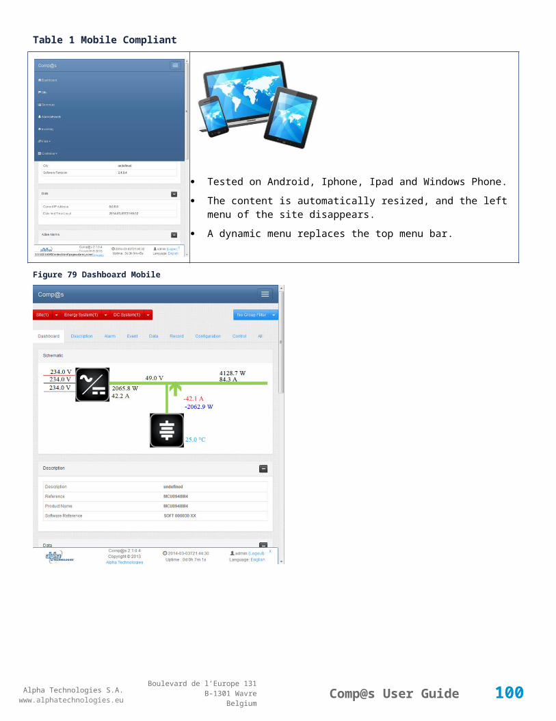
Alpha Technologies S.A.www.alphatechnologies.eu
Alpha Technologies S.A.www.alphatechnologies.eu
Comp@s User GuideBoulevard de l’Europe 131
B-1301 WavreBelgium
Parameter name Value Description
you set this parameter to 0, you will get all the events.
notable true/false This is an option to receive no table at all but you can still add some table you want with the corresponding parameters set to true.
These parameters are passed in the URI. The order of the parameters is free, and none is mandatory.
For example, if we want to retrieve the data table and the alarm table up to the third level of hierarchy, the URI is:
URI examplehttp://the_site_ip/site.xml?description=false&alarm=true&event=false&data=true&
data_record=false&config=false&level=3
If no option is set, the whole file is sent, except data record table and control table.
Some other files can also be retrieved, with the same available options:
File Name Description
energy_system.xml You get only the energy system XML part
dc_system.xml or dc_system1.xml You get only the first dc system XML part
dc_system2.xml You get only the second dc system XML part
configuration.xml You get the actual user configuration file of the system
These XML files are compliant with the ETSI ES 202 336 standard, a summary of the relevant parts is available in ETSI Protocol .
5.1.3 Retrieving data records in CSV format
It is possible to download data records in CSV format (Comma-Separated values). This allows using these records in Microsoft Excel for statistical and advanced charting purpose.
These files can be downloaded through the web interface, in the “records” tab of any element. It is possible to download the records of average, minimum and maximum values of data element. The period of time can be a second, a minute, an hour or a day:
Figure 83 CSV data records
100

Alpha Technologies S.A.www.alphatechnologies.eu
Alpha Technologies S.A.www.alphatechnologies.eu
Comp@s User GuideBoulevard de l’Europe 131
B-1301 WavreBelgium
Please note that this function requires the “asset” license.
5.1.4 HTTP GET of any description, data, configuration, etc.It is possible to retrieve easily element values trough a simple HTTP get request. This can be considered as an equivalent of an SNMP get, but over HTTP. The following examples illustrate some requests:
Get local time:
Get local timehttp://<the ip address>/get.txt?path=/site/data_table/21
Get dc system 1 bus voltage:
Get dc system 1 bus voltagehttp://<the ip address>/get.txt?path=/site/energy_system/dc_system/data_table/11
Get severity type of the alarm 1 of the dc system:
Get severity typehttp://<the ip address>/get.txt?path=/site/energy_system/dc_system/alarm_table/1/severity_type
5.1.5 HTTP POST to configure and control Introduction to HTTP POST and implementation
SetValue.cgi
ProcessXML.cgi.
5.1.5.1 Introduction to HTTP POST and implementationThe Comp@s web server supports some HTTP POST command.
Here follows the source code of a simple c# implementation of the post. You can easily use it with test the code with the free environment Microsoft C# Express.
The function takes as parameter:
the URL of the post
the data string to send in the body of the post
the login of an user allowed to change values for this equipment
the password of this user.
101
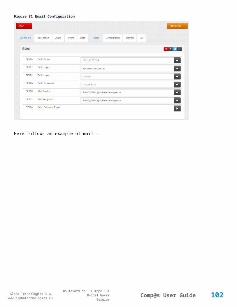
Alpha Technologies S.A.www.alphatechnologies.eu
Alpha Technologies S.A.www.alphatechnologies.eu
Comp@s User GuideBoulevard de l’Europe 131
B-1301 WavreBelgium
Table 2 C# code
public string PostMsg(string url, string postdata, string login, string password){ WebRequest webRequest = WebRequest.Create(url); webRequest.ContentType = "application/x-www-form-urlencoded"; Encoding asciiEncoding = Encoding.ASCII; byte[] byteArray = new byte[asciiEncoding.GetByteCount("xxx:xxx")]; byteArray = asciiEncoding.GetBytes(login+":"+password); webRequest.Headers.Add(HttpRequestHeader.Authorization, "Basic " + Convert.ToBase64String(byteArray)); webRequest.Method = "POST"; byte[] bytes = Encoding.ASCII.GetBytes(postdata); Stream os = null; try { // send the Post webRequest.ContentLength = bytes.Length; //Count bytes to send os = webRequest.GetRequestStream(); os.Write(bytes, 0, bytes.Length); //Send it } catch (WebException ex) { return "error"; } finally { if (os != null) { os.Close(); } } try { // get the response WebResponse webResponse = webRequest.GetResponse(); if (webResponse != null) { StreamReader sr = new StreamReader(webResponse.GetResponseStream()); return sr.ReadToEnd().Trim(); } } catch { return "error"; } return "error";}
C#public string PostMsg(string url, string postdata, string login, string password)
102

Alpha Technologies S.A.www.alphatechnologies.eu
Alpha Technologies S.A.www.alphatechnologies.eu
Comp@s User GuideBoulevard de l’Europe 131
B-1301 WavreBelgium
{
WebRequest webRequest = WebRequest.Create(url);
webRequest.ContentType = "application/x-www-form-urlencoded";
Encoding asciiEncoding = Encoding.ASCII;
byte[] byteArray = new byte[asciiEncoding.GetByteCount("xxx:xxx")];
byteArray = asciiEncoding.GetBytes(login+":"+password);
webRequest.Headers.Add(HttpRequestHeader.Authorization, "Basic " + Convert.ToBase64String(byteArray));
webRequest.Method = "POST";
byte[] bytes = Encoding.ASCII.GetBytes(postdata);
Stream os = null;
try
{ // send the Post
webRequest.ContentLength = bytes.Length; //Count bytes to send
os = webRequest.GetRequestStream();
os.Write(bytes, 0, bytes.Length); //Send it
}
catch (WebException ex)
{
return "error";
}
finally
{
if (os != null)
{
os.Close();
}
}
try
{ // get the response
WebResponse webResponse = webRequest.GetResponse();
if (webResponse != null)
{
StreamReader sr = new StreamReader(webResponse.GetResponseStream());
return sr.ReadToEnd().Trim();
}
}
103

Alpha Technologies S.A.www.alphatechnologies.eu
Alpha Technologies S.A.www.alphatechnologies.eu
Comp@s User GuideBoulevard de l’Europe 131
B-1301 WavreBelgium
catch { return "error"; }
return "error";
}
5.1.5.2 SetValue.cgiThe arguments to pass in the HTTP POST body are:
path : this is the path to the parameter to change
value : this is the new value
Here is an example of code to manually set the local time:
C#string path = "/site/1/control_table/control/12";
string value = System.DateTime.Now.ToString("s");
string postdata = "path=" + path + "&value=" + value;
PostMsg("http://192.168.45.2/SetValue.cgi", postdata, "admin", "compas");
5.1.5.3 ProcessXML.cgiThis function can be used to configure multiple parameters in one command. It is possible to send a full XML structure (like the configuration.xml) in the post data. All the valid elements will be updated with the new value.
This allows to remotely changing multiple config parameters by posting on each IP where a Comp@s monitoring is running.
5.2 FTP Server Connecting the Comp@s FTP Server
Changing default login and password.
5.2.1 Connecting the Comp@s FTP Server
In order to use the FTP functionalities of Comp@s, you need a FTP client installed. We recommend the use of “Filezilla”, a free FTP solution available at http://filezilla-project.org/.
The connection parameters are:
IP address / Host The IP of your system
Port 21
Default login admin
Default password compas
104
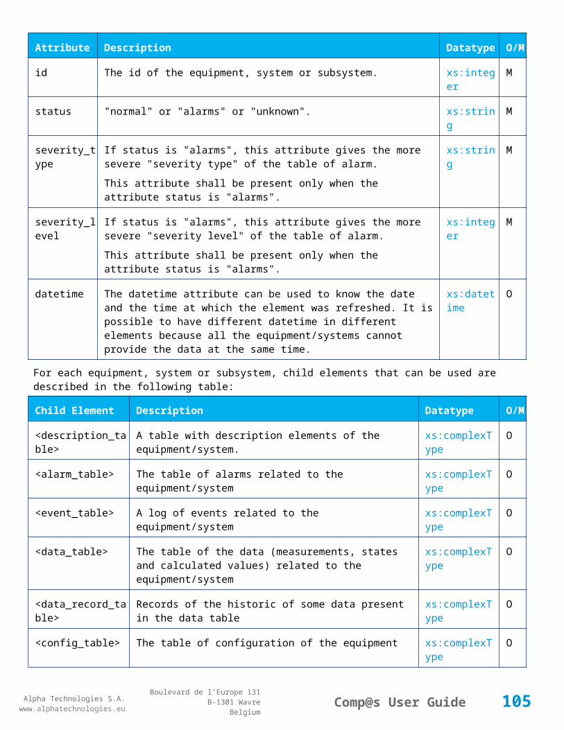
Alpha Technologies S.A.www.alphatechnologies.eu
Alpha Technologies S.A.www.alphatechnologies.eu
Comp@s User GuideBoulevard de l’Europe 131
B-1301 WavreBelgium
5.2.2 Changing default login and passwordThe passwords are independent from the main Comp@s application. There are managed in an independent XML file named “Compas_FTPServer.xml” located in the “user” folder. If this file does no exist, the default login and password are used:
STEP 1: Start a text editor like Notepad
STEP 2: Copy –Paste the following content:
XML<ftpserver>
<ftpusers>
<user login="admin" password="compas"/>
</ftpusers>
</ftpserver>
STEP 3: Modify the login and password
STEP 4: Save the file as “Compas_FTPServer.xml”
STEP 5: Copy that file in the “\\FlashDisk\\user” (“\\Nor Flash\\user” on previous release).
STEP 6: You have to use the new login and password at the next FTP connection.
Remark 1You can create multiple ftp users by adding more than one <user/> node under the <ftpusers/> node.
Remark 2If you want to keep your password more secret, it is possible to provide a hashed version of the password with the following syntax:
XML<ftpserver>
<ftpusers>
<user login="admin" passwordHash="1F41C076E8B0C2B69FD36514C54BD86F"/>
</ftpusers>
</ftpserver>
105

Alpha Technologies S.A.www.alphatechnologies.eu
Alpha Technologies S.A.www.alphatechnologies.eu
Comp@s User GuideBoulevard de l’Europe 131
B-1301 WavreBelgium
5.3 Modbus SlaveWith the Modbus license, a DC system can be monitored with the Modbus over TCP/IP protocol. Here follows the exchange table between the supervisor and the Comp@s monitoring. The Modbus transport layer is Ethernet over TCP/IP. The default used port is 502:
Discrete Inputs (Read Only)
Input Registers (Read Only)
Discrete Coils Table (Command).
If you want to use Modbus to monitor other type of system, please contact us, we will study the business case and make a proposal.
5.3.1 Discrete Inputs (Read Only)
Each discrete input is associated with an alarm related to the DC System level. This table corresponds to the alarm table in Tables at the DC System level.
Index
Name Help
1 DC Bus Extra Low The bus voltage is extra low
2 DC Bus Low The bus voltage is low
3 DC Bus High The bus voltage is high
4 DC Bus Extra High The bus voltage is extra high
5 DC Bus Voltage Sense Failure
The DC bus voltage sense is defect or unconnected
6 Mains Failure All the phases are down
7 Mains Partial Failure Some rectifiers are in AC Failure
8 Mains Low The main voltage is low on one or more phases
9 Mains High The main voltage is high on one or more phases
10 One Rectifier Failure One rectifier must be replaced
11 More Than One Rectifier Failure
More than one rectifier must be replaced
12 Missing Rectifiers There is not enough rectifier according to the minimal number of rectifier configuration element
13 Battery Last Test Failed
The last battery test did not succeed. Maybe the battery should be replaced.
14 Battery On Discharge The battery is discharging. This means that the load is too high for the installed rectifiers. This alarm is inactive when the system in AC Failure.
106
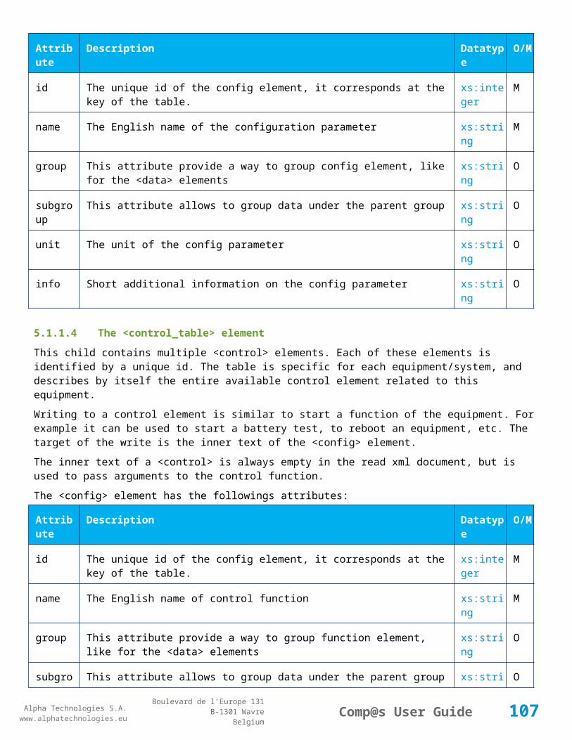
Alpha Technologies S.A.www.alphatechnologies.eu
Alpha Technologies S.A.www.alphatechnologies.eu
Comp@s User GuideBoulevard de l’Europe 131
B-1301 WavreBelgium
Index
Name Help
17 Battery LVD Relay Open
The battery Low Voltage Disconnector is open.
18 Battery Temperature Too High
The temperature of the battery is too high.
19 Battery Temperature Too Low
The temperature of the battery is too low.
20 Battery Temperature Sensor Fail
The battery temperature sense (NTC) is not connected or is defect.
21 Ambient Temperature Too High
The ambient temperature is too high.
22 Ambient Temperature Too Low
The ambient temperature is too low.
23 Ambient Temperature Sensor Fail
The ambient temperature sense (NTC) is not connected or is defect
25 Digital Input 1 This alarm is related to digital input 1
26 Digital Input 2 This alarm is related to digital input 2
27 Digital Input 3 This alarm is related to digital input 3
28 Digital Input 4 This alarm is related to digital input 4
29 Digital Input 5 This alarm is related to digital input 5
30 Digital Input 6 This alarm is related to digital input 6
31 Digital Input 7 This alarm is related to digital input 7
32 Digital Input 8 This alarm is related to digital input 8
If custom alarms are defined with the PLC, they are available starting from index 101.
5.3.2 Input Registers (Read Only)These input registers correspond to the main data related to the DC System level. All these values are coded as signed 16 bits:
Index
Name: Group Unit Help
1 DC Mode General The DC system can be in 4 possible states:
FLOAT : 0
BOOST : 1
BATTERY_TEST : 2
107

Alpha Technologies S.A.www.alphatechnologies.eu
Alpha Technologies S.A.www.alphatechnologies.eu
Comp@s User GuideBoulevard de l’Europe 131
B-1301 WavreBelgium
Index
Name: Group Unit Help
AC_FAILURE : 3
2 Previous DC Mode General The DC system was previously in one of the 4 possible states:
FLOAT : 0
BOOST : 1
BATTERY_TEST : 2
AC_FAILURE : 3
5 Day OS Can be used to read the date and time.
6 Month OS
7 Year OS
8 Hour OS
9 Minute OS
10 Second OS
11 Bus Voltage General 0.1 Volt The DC bus voltage in volt.
12 Ratio Delivered On Available Power
General 0.01 % This is the ratio of the delivered power divided by the installed power, in %.
13 Hours Since Last AC Failure Begin
General hour The number of hours since the last AC Failure begin
14 Hours Since Last AC Failure End
General hour The number of hours since the last AC Failure end
21 Rectifiers Output Power
Rectifiers
100 Watt
The sum of the delivered rectifier power
22 Rectifiers Output Current
Rectifiers
Ampere The sum of the delivered rectifier current
23 Rectifiers Output Power Max
Rectifiers
100 Watt
The sum of the deliverable rectifier power
24 Rectifiers Output Current Max
Rectifiers
Ampere The sum of the deliverable rectifier current
31 Number Of Rectifier Max
Rectifiers
The maximum possible number of rectifier in this dc system
32 Number Of Present Rectifier
Rectifiers
The actual number of present rectifier in this dc system
33 Number Of Absent Rectifier The actual number of absent rectifier in this dc system
108

Alpha Technologies S.A.www.alphatechnologies.eu
Alpha Technologies S.A.www.alphatechnologies.eu
Comp@s User GuideBoulevard de l’Europe 131
B-1301 WavreBelgium
Index
Name: Group Unit Help
Rectifier s
34 Number Of Active Rectifier
Rectifiers
The actual number of active rectifier in this dc system. An active rectifier is a rectifier which is present, DC OK, AC OK and not in remote off.
35 Number Of AC-Fail Rectifier
Rectifiers
The actual number or rectifier in AC Failure.
36 Number Of DC-Fail Rectifier
Rectifiers
The actual number or rectifier with DC Failure.
37 Number Of Remote Off Rectifier
Rectifiers
The actual number or rectifier in remote off.
38 Number Of Over Temperature Rectifier
Rectifiers
The actual number or rectifier in OVer Temperature.
41 AC Phase 1 Voltage
AC 0.1 Volt The voltage on AC phase 1
42 AC Phase 2 Voltage
AC 0.1 Volt The voltage on AC phase 2
43 AC Phase 3 Voltage
AC 0.1 Volt The voltage on AC phase 3
51 Load Power Load 100 Watt
Estimation of the load power consumption
52 Load Current Load Ampere Estimation of the load current consumption
61 Battery Input Current
Battery Ampere Measurement of the battery input current. A negative value means that the battery is discharging
62 Battery Input Power Battery 100 Watt
Measurement of the battery input power. A negative value means that the battery is discharging
71 Battery Temperature
Battery 0.1 °C The battery temperature
72 Battery Test State Battery This is about the result of the last battery test. 9 values are possible :
NEVER_TESTED : 0
SUCCESS : 1
ON_GOING : 2
FAILED_TIMEOUT : 3
FAILED_VBUS_TOO_LOW : 4
FAILED_LOAD_TOO_LOW : 5
109

Alpha Technologies S.A.www.alphatechnologies.eu
Alpha Technologies S.A.www.alphatechnologies.eu
Comp@s User GuideBoulevard de l’Europe 131
B-1301 WavreBelgium
Index
Name: Group Unit Help
FAILED_AC_FAILURE : 6
FAILED_CANCELED : 7
FAILED_LVD_OPENED : 8
73 Battery Test Discharged Capacity
Battery 0.01% This is the battery capacity, in percent, discharged during the last battery test. This value is updated at the end of the battery test.
74 Battery Test Discharged Capacity Ah
Battery Ah This is the battery capacity, in ampere hour, discharged during the last battery test. This value is updated at the end of the battery test.
75 Battery Test Final Voltage
Battery 0.1 Volt This is the bus voltage at the end of the last battery test. This value is updated at the end of the battery test.
5.3.3 Discrete Coils Table (Command)These outputs Boolean register correspond to the entries for controlling the DC System. All these commands are also executable with the CDM (Comp@s Display Module).
In order to start the command, a “1” must be written to this entry. The value is directly reset to 0 on the command start.
ID Name Group Help
1 Back To Float DC Mode
The dc system must go back in floating mode.
2 Start Battery Test DC Mode
The dc system must start a battery test.
3 Force Battery Test DC Mode
The dc system must force a battery test.
4 Start Boost Mode DC Mode
The dc system must go in boost mode.
11
Open The LVD LVD The LVD must be opened
12
Close The LVD LVD The LVD must be closed
31
Reset Battery Current Integration
Battery Reset the integration of the battery current.
41
Reset Last Battery Test State
Battery Reset the state of the last battery test. If an alarm 'Battery Last Test Failed' is set, the alarm will be cleared.
110

Alpha Technologies S.A.www.alphatechnologies.eu
Alpha Technologies S.A.www.alphatechnologies.eu
Comp@s User GuideBoulevard de l’Europe 131
B-1301 WavreBelgium
5.4 SNMP Agent For SNMP Agent: see The Comp@s SNMP Agent
Using and Configuring SNMP traps.
5.4.1 Using and Configuring SNMP traps
SNMP Comp@s configuration
Sending a testing trap
Receiving traps.
5.4.1.1 SNMP Comp@s configuration
STEP 1: Connect the Comp@s web server
STEP 2: Browse to Site -> Configuration
STEP 3: Check that SNMP Activated is “True”.
STEP 4: Configure the “SNMP” targets IP”, further in the page. This parameter can be filled with multiple IP address separated by coma. Example: “130.145.23.1, 130.23.12.45”.
STEP 5: Check that “Minimal Event Severity For Traps” is set to “none”. This is the minimal severity of the event to send a SNMP trap. You can set this parameter to “warning”, “minor”, “major” or “critical”.
STEP 6: Repeat STEP 4 and STEP 5 at the DC System level and on the Sensors and Actuators if you have. This allows sending traps to different servers in function of the concerned equipment.
Your system is now configured; each event will be sent by trap.
5.4.1.2 Sending a testing trap
STEP 1: Connect the Comp@s web server
STEP 2: Browse to Site -> Control or to DC System -> Control
STEP 3: At the bottom of the page, you can enter a text in the field called “Add Event”.
STEP 4: Click on the corresponding “Execute” button.
STEP 5: An event has been added and was sent trough traps.
5.4.1.3 Receiving trapsIn order to receive traps, you need SNMP software able to receive traps. You can download the free Ireasoning MIB Browser which can do the job. The install file is available at: http://www.ireasoning.com/mibbrowser.shtml.
111

Alpha Technologies S.A.www.alphatechnologies.eu
Alpha Technologies S.A.www.alphatechnologies.eu
Comp@s User GuideBoulevard de l’Europe 131
B-1301 WavreBelgium
Once you have installed the MIB browser and loaded the MIB. You can use the “Trap Receiver” located in tools:
Figure 84 IReasoning trap receiver
5.5 XML Event Posting (ETSI)
The controller can send XML events, in compliance with ETSI standard ES-202-336, part 1.The relevant chapter is 9.4.2 (Alarm and Event Message). The standard is available free of charge on www.etsi.org. (http://pda.etsi.org/pda/queryform.asp allows to search for ES 202 336).
At the site level, in configuration, it is possible to configure what table must be sent in case of event (description, alarm, config, etc.) The following screenshot show some of the configuration elements. Up to 2 servers can be configured to allow redundancy.
112
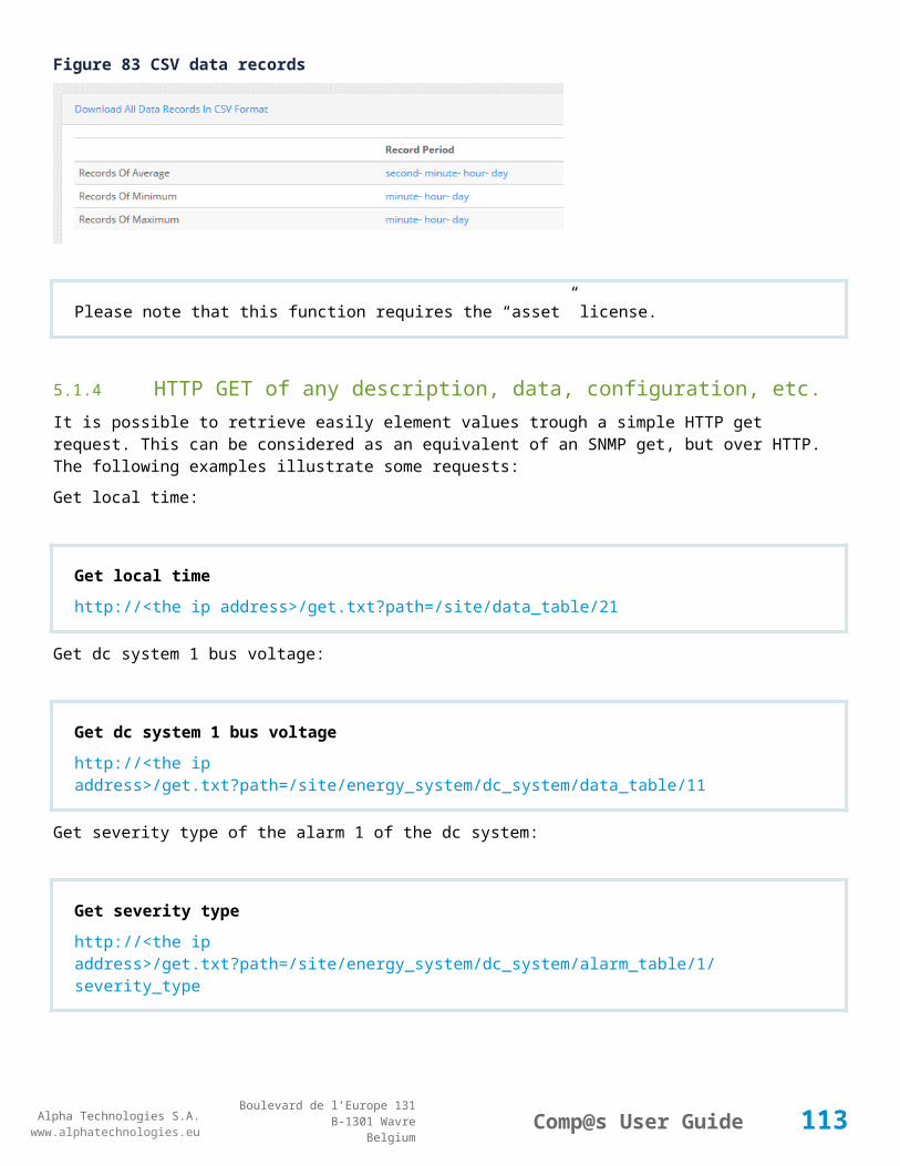
Alpha Technologies S.A.www.alphatechnologies.eu
Alpha Technologies S.A.www.alphatechnologies.eu
Comp@s User GuideBoulevard de l’Europe 131
B-1301 WavreBelgium
Some configuration elements about the XML Event Posting (See site tables for more information.)
The following c# code is an example to create an http listener that can receive events.
using System; using System.Collections.Generic; using System.IO; using System.Linq; using System.Threading; using System.Net; using System.Xml;namespace HelpDebugPostXml { public class XmlPostListener {
private Thread _threadServer; private Thread _threadDecodeXml;private Form1 form1;
public XmlPostListener(Form1 form1) {
this.form1 = form1; }
public void StartListening() {
_threadServer = new Thread(ThreadServer); _threadServer.Start();
}public void StopListning() {
if (_httpListener != null && _httpListener.IsListening)
113

Alpha Technologies S.A.www.alphatechnologies.eu
Alpha Technologies S.A.www.alphatechnologies.eu
Comp@s User GuideBoulevard de l’Europe 131
B-1301 WavreBelgium
_httpListener.Stop(); }public void Stop() {
StopListning(); }
private System.Threading.AutoResetEvent listenForNextRequest = new System.Threading.AutoResetEvent(false);
private HttpListener _httpListener;
private void ThreadServer() {
try {
_httpListener = new HttpListener(); _httpListener.Prefixes.Clear();
_httpListener.Prefixes.Add(form1.textBoxPostUrl.Text);_httpListener.Start();System.Threading.ThreadPool.QueueUserWorkItem(Listen);
} catch (Exception ex) {
System.Windows.Forms.MessageBox.Show("Error : " + ex.Message);
}}
// Loop here to begin processing of new requests.
private void Listen(object state) {
while (_httpListener.IsListening) {
_httpListener.BeginGetContext(new AsyncCallback(ListenerCallback), _httpListener);
listenForNextRequest.WaitOne(); }
}
private void ListenerCallback(IAsyncResult result) {
HttpListener listener = result.AsyncState as HttpListener;
HttpListenerContext context = null;
if (listener == null) return;
try
114

Alpha Technologies S.A.www.alphatechnologies.eu
Alpha Technologies S.A.www.alphatechnologies.eu
Comp@s User GuideBoulevard de l’Europe 131
B-1301 WavreBelgium
{ context = listener.EndGetContext(result);
} catch (Exception ex) {
System.Windows.Forms.MessageBox.Show("Error : " + ex.Message);
return; } finally {
listenForNextRequest.Set(); }
if (context == null) return;
ProcessRequest(context);
}
private void ProcessRequest(HttpListenerContext context) {
string s = ""; HttpListenerRequest request = null; HttpListenerResponse response = null;
try {
request = context.Request; response = context.Response;response.KeepAlive = false; response.SendChunked = false;
Stream body = request.InputStream; var encoding = request.ContentEncoding; var reader = new StreamReader(body, encoding);
s = reader.ReadToEnd(); body.Close(); reader.Close();
if (request.RemoteEndPoint == null) {
response.Abort(); return;
}
} catch (Exception ex) {
System.Windows.Forms.MessageBox.Show("Error : " + ex.Message);
response.Abort(); return;
}
115
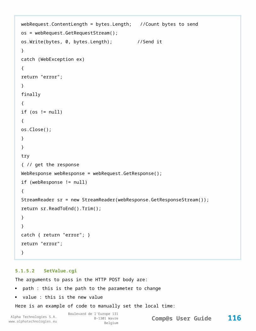
Alpha Technologies S.A.www.alphatechnologies.eu
Alpha Technologies S.A.www.alphatechnologies.eu
Comp@s User GuideBoulevard de l’Europe 131
B-1301 WavreBelgium
System.Windows.Forms.MethodInvoker m = delegate {
form1.richTextBox1.Text += '\n' + s; }; form1.richTextBox1.BeginInvoke(m);
//We send to the compas that we have received the messageresponse.StatusCode = (int) HttpStatusCode.OK; const string responseString = "OK"; byte[] buffer = System.Text.Encoding.UTF8.GetBytes(responseString);
// Get a response stream and write the response to it. response.ContentLength64 = buffer.Length;
Stream output = response.OutputStream; output.Write(buffer, 0, buffer.Length); // You must close the output stream. output.Close(); response.Close();
} }}
Here is an example of event received, when the data and alarms are requested on event :
116
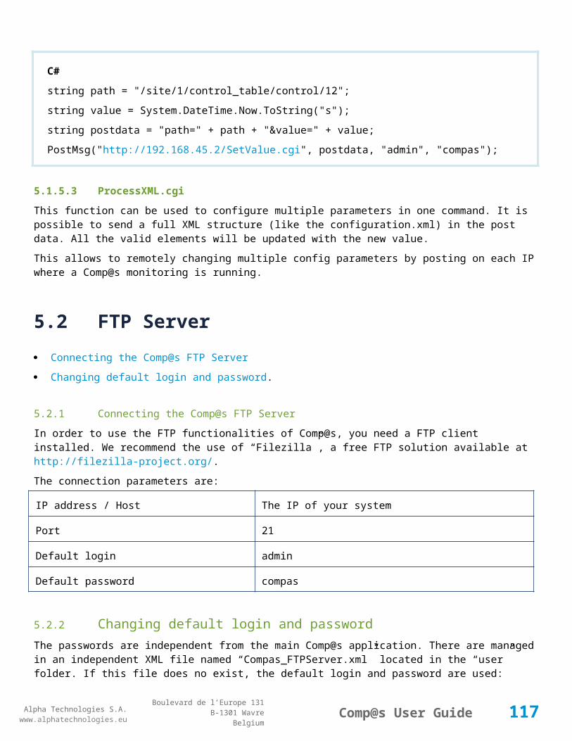
Alpha Technologies S.A.www.alphatechnologies.eu
Alpha Technologies S.A.www.alphatechnologies.eu
Comp@s User GuideBoulevard de l’Europe 131
B-1301 WavreBelgium
Arm@da, our server application, is managing all these events, by filling in a mysql database. Please contact your reseller for more information.
117

Alpha Technologies S.A.www.alphatechnologies.eu
Alpha Technologies S.A.www.alphatechnologies.eu
Comp@s User GuideBoulevard de l’Europe 131
B-1301 WavreBelgium
6 CAN BUS RELATED INFORMATION
CAN Bus - The internal field bus
Connecting multiple rectifier shelves together.
6.1 CAN Bus - The internal field bus
Comp@s systems use the CAN bus to communicate with the equipment. The CAN bus Controller Area Network (CAN) is an ISO approved standard for a low cost real time communication protocol. It is a fault tolerant and robust system. It is commonly used in automobiles, automated robots, airplanes, etc. In our application, the maximal bus length is 500m. The monitoring application is able to detect BUS problems like a short between the lines of the bus or devices which are unreachable.
Each node connected on the CAN Bus has an id. These ids are defined as shown in the following table:
Equipment Type Range Comments
Node Rectifier [1,100] Each rectifier with CAN capabilities has an address comprised between 1 and 100.
Node MCU Remote Central
[100,1]
Node MCU [101,110]
Up to 10 shelves monitoring (MCU)
Node Extension [111,126]
Up to 10 extension card.
Node_CDM [126] Comp@s display module
Node Comp@s [127] The Comp@s node id. (used by CDM)
To see the list of the nodes connected on a Comp@s System, browse to Site -> Data. There, you can view the "CAN Bus Node IDs" list, as shown on the following figure:Figure 85 CAN Bus Node IDs
118

Alpha Technologies S.A.www.alphatechnologies.eu
Alpha Technologies S.A.www.alphatechnologies.eu
Comp@s User GuideBoulevard de l’Europe 131
B-1301 WavreBelgium
6.2 Connecting multiple rectifier shelves together
It is possible to interconnect multiple shelves to increase the system power. If the DC outputs are interconnected, the shelves are working in parallel. If the DC outputs of the shelves are independent, the shelves are independent.
In both situations, the CAN bus has to be connected between the shelves. Each MCU must have a unique CAN Id.
On MCU1848, the DIP Switch use is described in the following table:
Switches
Parameter Description
1-3 CAN Id Unique identifier of the MCU on the CAN bus.MCU CAN Id range begins at 101 and switch [1-3] represents a LSB encoded binary value that defines 8 successive Id's from 101 to 109.
4-6 - Reserved for future use
7 Master/Slave
OFF: this MCU behaves as the master of the systemON: this MCU behaves as a slave of master MCU
8 Termination OFF: external CAN bus termination must be usedON: CAN bus is internally terminated by a 147Ω resistor
Multiple Shelves working in parallel
Multiple Shelves Independent.
6.2.1 Multiple Shelves working in parallel
The CAN bus, VPROG and Sharing signals must be interconnected between the shelves. The whole system is seen as only one DC system by Comp@s. Here follows two typical configurations:
Figure 86 Example with a system with 2 shelves of 6x1800W rectifiers
119
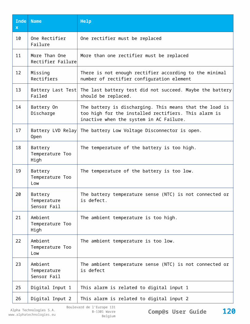
Alpha Technologies S.A.www.alphatechnologies.eu
Alpha Technologies S.A.www.alphatechnologies.eu
Comp@s User GuideBoulevard de l’Europe 131
B-1301 WavreBelgium
Figure 87 Example with a system of 3 shelves of 6x1800W rectifiers
6.2.2 Multiple Shelves Independent
An independent shelf will manage the bus voltage, the alarms, the LVD, etc. Multiple DC systems are seen by Comp@s:
Figure 88 Example with a system with 2 shelves of 6x1800W rectifiers
120
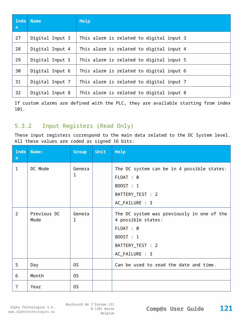
Alpha Technologies S.A.www.alphatechnologies.eu
Alpha Technologies S.A.www.alphatechnologies.eu
Comp@s User GuideBoulevard de l’Europe 131
B-1301 WavreBelgium
7 E Q U I P M E N T T A B L E S
The following chapters list the description, data, alarm, configuration and control tables that will be available in Comp@s for most of the supported devices. (Rectifier, MCU, Extension board, etc.)
7.1 Site Tables
7.1.1 COMPAS
Device Information
Name COMPAS
Short Description Comp@s Platform Card
Long Description
Hardware Reference 4004 110 96531
Software Reference SOFT 000031 XX
Equipment Type General for all Comp@s
ETSI Level /site/
Description Table
Id Name Group SubGroup License
1 Site Number Description Site Information basic
The identification number of the site
2 Site Name Description Site Information basic
The name of the site
3 Short Description Description Site Information basic
A short description of the site
4 Info Description Site Information basic
Some more information about the site
5 Description Description Custom Description basic
A free text zone to write a system description
121

Alpha Technologies S.A.www.alphatechnologies.eu
Alpha Technologies S.A.www.alphatechnologies.eu
Comp@s User GuideBoulevard de l’Europe 131
B-1301 WavreBelgium
Description Table
6 Reference Description Custom Description basic
A free text zone to write the customer reference of the system
7 Contact Name Description Contact basic
Contact Name
8 Phone Number Description Contact basic
Phone Number
11 Street Description Address basic
Street part of the site address
12 City Description Address basic
City part of the site address
13 Province Description Address basic
Province part of the site address
14 Postal Code Description Address basic
Postal Code part of the site address
15 Region Description Address basic
Region part of the site address
16 Country Description Address basic
Country part of the site address
21 Group 1 Description Clustering basic
Group Level 1 (For Armada Clustering)
22 Group 2 Description Clustering basic
Group Level 2 (For Armada Clustering)
23 Group 3 Description Clustering basic
Group Level 3 (For Armada Clustering)
24 Group 4 Description Clustering basic
Group Level 4 (For Armada Clustering)
122
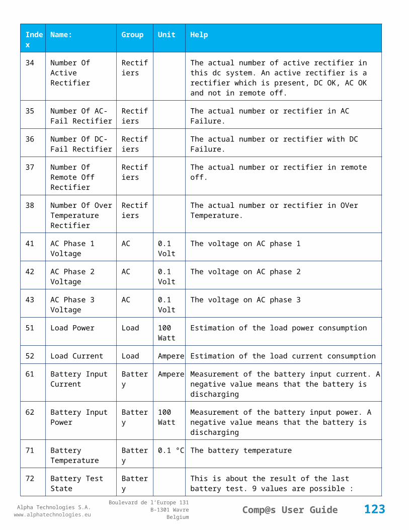
Alpha Technologies S.A.www.alphatechnologies.eu
Alpha Technologies S.A.www.alphatechnologies.eu
Comp@s User GuideBoulevard de l’Europe 131
B-1301 WavreBelgium
Description Table
25 Group 5 Description Clustering basic
Group Level 5 (For Armada Clustering)
31 Latitude Description GPS Position asset
The latitude of the site
32 Longitude Description GPS Position asset
The longitude of the site
33 Altitude Description GPS Position asset
The altitude of the site
91 Software Revision Controller Product Info basic
The software revision of Comp@s (read only)
92 Operating System Revision Controller Operating System Info basic
The operating system of Comp@s (read only)
93 CPU Controller Hardware Info basic
Information about the CPU
Alarm Table
Id Name Group SubGroup Severity Type (Level)
Set/Clear Delay
1 CAN Bus Failure Inventory CAN Bus major (0) 5 / 2
This alarm is active when there is a problem with the CAN Bus.
2 CAN Bus Addressing Error Inventory CAN Bus major (0) 5 / 2
This alarm is active if 2 devices or more are using the same CAN address. You need to remove the duplication problem et reboot the compas to avoid a possible strange behavior.
3 Missing CAN Bus Node IDs Inventory CAN Bus major (6) 10 / 2
This alarm is active if configured node ids are not detected on the bus
4 Running CAN LSS Device Detection
Inventory CAN Bus warning (0) 5 / 2
This alarm is active when new devices are beeing detected.
5 Running CAN Firmware Inventory CAN Bus warning (0) 5 / 2
123

Alpha Technologies S.A.www.alphatechnologies.eu
Alpha Technologies S.A.www.alphatechnologies.eu
Comp@s User GuideBoulevard de l’Europe 131
B-1301 WavreBelgium
Alarm Table
Upgrade
This alarm is active when the bootloader is upgrading a can device, or when the queue of upgrade is not empty
6 RS 485 Bus Failure Inventory RS485 Bus major (0) 5 / 2
This alarm is active when there is a problem with the RS 485 bus
11
Controller Reboot Required Controller Reboot major (0) 5 / 2
This alarm is active if the system should be rebooted for some reason
15
Last Configuration Changes Unsaved
Controller Save warning (2) 1 / 2
This alarm is active if the system should be rebooted for some reason
21
XML Heartbeat Post Failure XML XML Event Posting
major (0) 5 / 2
This alarm is active when the heartbeat is not accepted by the primary or the secondary post server. Please note that this alarm is inactive if the heartbeat mechanism is inactive.
Data Table
Id Name Group SubGroup Unit License
1 Current IP Address Network basic
This is the actual IP address of the Comp@s platform. If the Ethernet cable is not correctly connected, the address will be 0.0.0.0.
2 Current IP Mask Network basic
This is the actual IP address of the Comp@s platform. If the Ethernet cable is not correctly connected, the address will be 0.0.0.0.
3 Current MAC Address Network basic
This is the MAC address of IP interface.
11
Licensed Options Controller License basic
This is the options of the actual license.
21
Date And Time Local Time basic
This is the local time of the monitoring.
2 Date And Time UTC Time basic
124
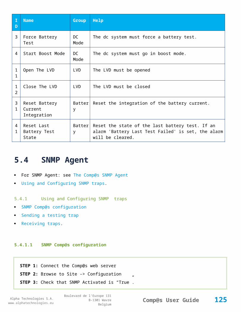
Alpha Technologies S.A.www.alphatechnologies.eu
Alpha Technologies S.A.www.alphatechnologies.eu
Comp@s User GuideBoulevard de l’Europe 131
B-1301 WavreBelgium
Data Table
2 This is the UTC time of the monitoring.
31
Monitoring Memory Used Controller Operating System Info Kb basic
This is actual amount of RAM memory used by the application.
32
CPU Percentage Usage Controller Operating System Info % basic
This is actual percentage of CPU used
33
Free Flash Memory Space Controller Operating System Info MBytes basic
This is free flash memory available on the Comp@s card, in Megabytes
41
Total Fifo Size Of Second Records Data Records basic
42
Total Fifo Size Of Minute Records Data Records basic
43
Total Fifo Size Of Hour Records Data Records basic
44
Total Fifo Size Of Day Records Data Records basic
51
CAN Bus Node IDs Inventory CAN Bus basic
The coma separated list of the node ids present on the CAN bus.
Config Table
Id Name Group SubGroup Unit Range: Min/Max (default) License
1 DHCP Enabled Network True/False (False) basic
The monitoring will try to get an IP with the DHCP protocol if this parameter is set to True. By default, this parameter is set to False.
2 IP Address If Static Network 192.168.45.1 basic
The static IP address of the monitoring. This configuration parameter is not used if the DHCP is enabled. The default IP is 192.168.45.2.
3 Subnet Mask If Static Network 255.255.255.0 basic
The static Subnet Mask of the monitoring. This configuration parameter is not used if the DHCP is enabled. The default mask is 255.255.255.0.
125

Alpha Technologies S.A.www.alphatechnologies.eu
Alpha Technologies S.A.www.alphatechnologies.eu
Comp@s User GuideBoulevard de l’Europe 131
B-1301 WavreBelgium
Config Table
4 Default Gateway If Static
Network 192.168.45.1 basic
The static Default Gateway of the monitoring. This configuration parameter is not used if DHCP is enabled. This is only useful if the monitoring have to use a gateway, this is generally not necessary. The default gateway is 192.168.45.1.
5 DNS If Static Network 192.168.45.1 basic
The static DNS of the monitoring. This configuration parameter is used to resolve URI and server name. This is not necessary if you are only IP address as target server. The default DNS server is 192.168.45.1.
8 Maximum Transmission Unit
Network basic
Specifies the TCP/IP MTU for the network interface
9 Ethernet Mode Network True/False (False) basic
The monitoring will try to get an IP with the DHCP protocol if this parameter is set to True. By default, this parameter is set to False.
11 SNTP Time Server Time 192.168.45.1 basic
The address of the server acting as SNTP timer server. If this server is not valid, the monitoring cannot update automatically his time. The default SNTP Time server is 192.168.45.1.
14 Time Zone Name Time ((GMT+01:00) Brussels, Copenhagen, Madrid, Paris)
basic
The Time Zone of the site
22 Web Server Security Enabled
Web Server
True/False (True) basic
This is a True/False parameter used to activate or deactivate the access control to the web server.
23 Web Server Port Web Server
0/65535 (80) basic
This is an unsigned integer parameter used to configure the port at which the web server is accessible. By default, the port is 80. If you change this port, you must be sure that the traffic is allowed by your switches and routers on this port.
24 Web Authentication Method
Web Server
basic
The web access security can be managed with 2 authentication methods: Basic Access or Digest Access. It is recommended to use the secured Digest access if security is an issue for you.
31 Default Page Web Server
basic
126

Alpha Technologies S.A.www.alphatechnologies.eu
Alpha Technologies S.A.www.alphatechnologies.eu
Comp@s User GuideBoulevard de l’Europe 131
B-1301 WavreBelgium
Config Table
The default page displayed on logon (dashboard, site, summary, alarm_event, ...)
41 XML Event Posting Activated
XML XML Event Posting
True/False (True) basic
This is a True/False parameter used to activate or deactivate the XML event posting.
42 XML Event Posting Refresh Time
XML XML Event Posting
second 1/3600 (2) basic
The minimal time in second between to calculation of the XML events to send. By default, this is done every two seconds.
43 XML Event Posting Timeout
XML XML Event Posting
millisecond 500/600000 (100000) basic
The timeout in millisecond when trying to post XML data to a Web Server.
45 XML Event Posting To Secondary Only If Primary Failure
XML XML Event Posting
True/False (True) basic
If this parameter is set to true, the events will be sent to secondary only if primary server is not available. If this parameter is set to false, all the events will be sent to primary and secondary server
46 XML Tables To Post On XML Event
XML XML Event Posting
description, alarm, data, config, control
basic
The list of the tables to send when an event is generated. (description,alarm,data,config,control). This allows to have armada database updated on event.
51 XML Heartbeat Time XML Heartbeat minute 0-2880 basic
This is the time between 2 XML Post of heartbeat. If set to 0, no heartbeat.
61 SNMP Activated SNMP True/False (True) basic
This is a True/False parameter used to activate or deactivate the SNMP agent.
63 SNMP Trap Version SNMP basic
Traps/Notification can be sent with SNMP V1, V2c or V3 format.
64 SNMP GET Minimum Security Level
SNMP basic
4 choices are available: No Authentication, V1 Community, V2c Community or V3.
65 SNMP SET Minimum Security Level
SNMP basic
4 choices are available: No Authentication, V1 Community, V2c Community or V3.
66 SNMP V3 Auth SNMP basic
127

Alpha Technologies S.A.www.alphatechnologies.eu
Alpha Technologies S.A.www.alphatechnologies.eu
Comp@s User GuideBoulevard de l’Europe 131
B-1301 WavreBelgium
Config Table
Algorithm
3 choices are available: MD5, SHA, Any
67 SNMP V3 Privacy Algorithm
SNMP basic
3 choices are available: DES, AES, 3DES
68 SNMP V3 Privacy Password
SNMP basic
The global SNMP V3 Encryption Password. This one is common for all the users to avoid complexity
69 SNMP V3 Engine ID SNMP basic
The SNMP V3 Local Engine ID string
72 SNMP V3 Trap Auth Algorithm
SNMP basic
2 choices are available: MD5, SHA
73 SNMP V3 Trap Privacy Algorithm
SNMP basic
3 choices are available: DES, AES, 3DES
74 SNMP V3 Trap Username
SNMP basic
The SNMP V3 Trap UserName used for all the SNMP V3 traps
75 SNMP V3 Trap Auth Password
SNMP basic
The SNMP V3 Trap Authentication Password
76 SNMP V3 Trap Privacy Password
SNMP basic
The SNMP V3 Trap Privacy Password
77 Site Description Ids Included In Traps
SNMP basic
List of site Description Elements to send on traps. (to have the site reference and the city in each trap for example). The list is seperated with ';'
81 Generate Event On Configuration Changes
Generic Events True/False (True) basic
This is a True/False parameter used to activate or deactivate the tracking of configuration changes
128

Alpha Technologies S.A.www.alphatechnologies.eu
Alpha Technologies S.A.www.alphatechnologies.eu
Comp@s User GuideBoulevard de l’Europe 131
B-1301 WavreBelgium
Config Table
82 Auto Archive Period Data Record
Data Records
hour basic
Period in hour to auto save records (when detailled and long duration records are needed). 0 means disabled.
83 Generate Event On Control Execution
Generic Events True/False (True) basic
This is a True/False parameter used to activate or deactivate the tracking of control execution
84 Generate Event On Alarm Acknowledge
Generic Events True/False (True) basic
This is a True/False parameter used to activate or deactivate the tracking of alarm acknowledgment
91 Required CAN Bus Node IDs
Inventory CAN Bus basic
This is a coma separated list with the required CAN bus node ids
92 LSS CAN id range Inventory CAN Bus basic
By default 50-100, means up to 50 Can Nodes like rectifiers with CAN Id 50 to 100. To support up to 100 rectifiers, change it to 1-100.
93 System Nodes Definition
Inventory CAN Bus basic
dc3(30-100)
95 LSS CANOpen Saved Configuration
Inventory CAN Bus basic
101
Administrator Login:Password
Users (admin:compas) basic
This is the login and the password of the administrator. It is saved with a special syntax. First the login in clear, followed of 2 points, followed of the MD5 hashed password. If you change the login:password by entering a non hashed password, this last is automatically hashed.
102
User 1 Login:Password Users (user1:compas) basic
This is the login and the password of the user number 1.
103
User 2 Login:Password Users (user2:compas) basic
This is the login and the password of the user number 2.
104
User 3 Login:Password Users (user3:compas) basic
This is the login and the password of the user number 3.
129

Alpha Technologies S.A.www.alphatechnologies.eu
Alpha Technologies S.A.www.alphatechnologies.eu
Comp@s User GuideBoulevard de l’Europe 131
B-1301 WavreBelgium
Config Table
105
User 4 Login:Password Users (user4:compas) basic
This is the login and the password of the user number 4.
106
User 5 Login:Password Users (user5:compas) basic
This is the login and the password of the user number 5.
120
Enable Email Feature Email True/False (False) asset
Enable/Disable the email feature
121
Smtp Server Email basic
Smtp Server. If you are using a domain name, make sure you configured the network Dns (CF5)
122
Smtp Domain Email basic
Smtp Domain. (Required by some servers.)
123
Smtp User Login:Password
Email basic
Smtp Login and Password. The password is encrypted. To enter a new login and password, enter login:password and validate, the password will be encrypted.
130
Mail Sender Email basic
Mail Sender (The 'From' of the emails you will receive)
131
Mail Recipients Email basic
Mail Recipients, seperated with semicolon ';'
135
Minimal Severity Type To Send Mail
Email (minor) basic
This is the minimal severity of the event to send a Summary Mail
210
RS485 Extensions Configuration
Inventory RS485 Bus PM9C(1) asset
The configuration string for RS485 Extensions
220
Ethernet Extensions Configuration
Inventory Ethernet AXS(192.168.45.3) asset
The configuration string for Ethernet Extensions
521
Read Access User Numbers
Generic Allowed Users
(1,2,3,4,5) basic
The list of the user numbers which have read access to this equipment. The user numbers are coma separated. The accepted user id are 1,2,3,4 and 5. Ex: 1,3,4
130

Alpha Technologies S.A.www.alphatechnologies.eu
Alpha Technologies S.A.www.alphatechnologies.eu
Comp@s User GuideBoulevard de l’Europe 131
B-1301 WavreBelgium
Config Table
522
Write Access User Numbers
Generic Allowed Users
() basic
The list of the user numbers which have write access to this equipment. This means that these users can modify the configuration element, the alarm settings and use the control elements. The user numbers are coma separated. The accepted user ids are 1,2,3,4 and 5. Ex: 1,3,4
601
Event Table Length Generic Events 10/4000 (100) basic
The maximum length of the table. The value must be comprised between 10 and 4000
611
SNMP Trap Targets IP SNMP 192.168.45.1 basic
One or multiple target IP to send traps, coma separated. Ex: 130.145.23.1, 130.23.12.45
612
Minimal Event Severity For Traps
SNMP (none) basic
This is the minimal severity of the event to send a SNMP trap
651
XML Events Primary Post URL
XML XML Event Posting
basic
This is the first URL at which the events related to this equipment must be posted. The XML ETSI standard is used in the posted data content.
652
XML Events Primary Post Login
XML XML Event Posting
basic
The login which must be used when posting events to the primary server
653
XML Events Primary Post Password
XML XML Event Posting
basic
The password which must be used when posting events to the primary server
661
XML Events Secondary Post URL
XML XML Event Posting
basic
This is the second URL at which the events related to this equipment must be posted. The XML ETSI standard is used in the posted data content. This allows having redundancy with the management server.
662
XML Events Secondary Post Login
XML XML Event Posting
basic
The login which must be used when posting events to the secondary server
663
XML Events Secondary Post Password
XML XML Event Posting
basic
The password which must be used when posting events to the secondary server
90 Number Of PLC Data PLC (0) plc
131

Alpha Technologies S.A.www.alphatechnologies.eu
Alpha Technologies S.A.www.alphatechnologies.eu
Comp@s User GuideBoulevard de l’Europe 131
B-1301 WavreBelgium
Config Table
1 The number of PLC data. Every equipment can manage up to 20 user programmable data. Data elements are automatically added in the data table. Configuration parameters are added to set the PLC Data Name and the PLC Data Mathematical calculation. In order to use these functionalities, you need a license with the 'PLC' module
902
Number Of PLC Alarm PLC (0) plc
The number of PLC alarm. Every equipment can manage up to 20 user programmable alarms. Alarm elements are automatically added in the alarm table. The alarm parameters are added to set the PLC Alarm Name and the PLC Alarm Boolean condition. In order to use these functionalities, you need a licence with the 'PLC' module
Control Table
Id Name Group SubGroup License
1 Reboot Controller Controller Reboot basic
Writing a '1' to this control element will reboot the monitoring. Events and Records will be saved.
2 Save Configuration And Reboot Controller Controller Reboot basic
Writing a '1' to this control element will first save the actual configuration and will reboot the monitoring after.
3 Reboot Monitoring Without Saving Records
Controller Reboot basic
Writing a '1' to this control element will reboot the monitoring without saving records
6 Apply Network Configuration Network basic
Writing a '1' to this control element will reconfigure the ethernet according to the Network Configuration. If you change the IP address in the config table without using this command after, the configuration is not applied.
11 Force SNTP Time Refresh Time basic
Writing a '1' to this control element will force the monitoring to try to refresh his time with the configured SNTP Time Server.
12 Set Local Time Time basic
Writing a date and time to this control element allows to manually change the local time of the monitoring. The syntax of the date and the time is: 2007-11-19T13:02:34
13 Set UTC Time Time basic
Writing a date and time to this control element allows to manually change the UTC time of the monitoring. The syntax of the date and the time is: 2007-11-19T13:02:34
14 Reset Uptime Time basic
132
Alpha Technologies S.A.www.alphatechnologies.eu
Alpha Technologies S.A.www.alphatechnologies.eu
Comp@s User GuideBoulevard de l’Europe 131
B-1301 WavreBelgium
Control Table
Writing a '1' to this control element will reset the uptime of the monitoring.
20 Clean and Save XML User Configuration Controller Save basic
Writing a '1' to this control element will remove the configuration sections related to missing equipments, than save all the configuration of all the connected equipment in a XML format. This file is read when the monitoring is starting in order to configure the monitoring. This file is also accessible trough the FTP server or can be downloaded trough the web interface.
21 Save XML User Configuration Controller Save basic
Writing a '1' to this control element will save all the configuration of all the connected (or previously connected) equipment in a XML format. This file is read when the monitoring is starting in order to configure the monitoring. This file is also accessible trough the FTP server or can be downloaded trough the web interface.
22 Save Inventory Controller Save underdev
Writing a '1' to this control element will save save the inventory in a XML format. This file is read when the monitoring is starting in order to configure the monitoring. This file is also accessible trough the FTP server or can be downloaded trough the web interface.
33 Save Data Records Data Records basic
Writing a '1' to this control element will force the monitoring to save all the data records. This is useful if you want to unpower the Comp@s monitoring. This function is called automatically everyday.
34 Export Data Records in CSV Data Records basic
Writing a '1' to this control element will force the monitoring to save all the CVS records files. The CSV files are stored in the records folder.
35 Archive Data Records Data Records basic
Writing a '1' to this control element will force the monitoring to save all the data records. This is useful if you want to unpower the Comp@s monitoring. This function is called automatically everyday.
36 Delete All Data Records Data Records basic
Writing a '1' to this control element will force the monitoring to save all the data records. This is useful if you want to unpower the Comp@s monitoring. This function is called automatically everyday.
40 Emulate Records Controller Emulation underdev
41 Reload Translations Controller Translation basic
Writing a '1' to this control element will reload all the csv translation files
51 Reload License Controller License basic
Writing a '1' to this control element will reload the license file
133

Alpha Technologies S.A.www.alphatechnologies.eu
Alpha Technologies S.A.www.alphatechnologies.eu
Comp@s User GuideBoulevard de l’Europe 131
B-1301 WavreBelgium
Control Table
61 Remove Absent Equipments Inventory basic
81 Reset CAN Bus Node Inventory CAN Bus basic
Writing a valid CAN bus node id to this control element will reset the correspondent device.
82 Save CANOpen LSS Configuration Inventory CAN Bus basic
83 Start New Inventory Inventory CAN Bus basic
91 Upgrade Node Firmware Inventory CAN Bus basic
This control element is used to start the firmware upgrade of a CAN bus Node. You need to upload first the firmware trough ftp in the /user/firmware path. Then you need to write the id number of the CAN Node, followed by a coma, followed by the file name. Example : '101,SOFT_0000030_01.txt'.
92 Cancel Firmware Upgrade Inventory CAN Bus basic
This control element is used to cancel the runiing firmware upgrade of a CAN bus Node.
103
Flash Binary Files basic
This control element is used to start a binary flash update. You need to upload first the firmware trough ftp in the /user/firmware path.
110
Download File From Url Files basic
This control element is used to download a file wiht HTTP get, the argument is an url. The file is saved in the upload folder
111
Delete User Uploaded File Files basic
This control element is used to delete a file in the user-upload folder. This is riskless as these files are not used, they are temporary files.
112
Move User Uploaded File Files basic
This control element is used to copy a file from the user-upload folder to another one. Be aware of what your are doing !
113
Extract Zip File in user-upload Files basic
This control element is used to delete a file in the user-upload folder. This is riskless as these files are not used, they are temporary files.
120
Send Summary Email Email asset
This control element is used to force the sending of a summary to the configured mail address
134
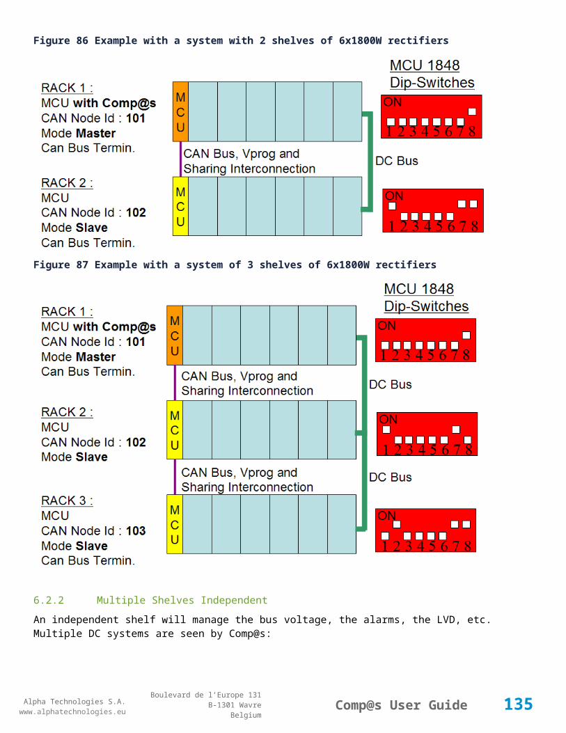
Alpha Technologies S.A.www.alphatechnologies.eu
Alpha Technologies S.A.www.alphatechnologies.eu
Comp@s User GuideBoulevard de l’Europe 131
B-1301 WavreBelgium
Control Table
501
Clear My Events Generic Events basic
By writing '1' to this control element, all the events of this equipment will be cleared.
502
Clear All Events Generic Events basic
By writing '1' to this control element, all the events of this equipment and all the events of all the sub-equipments will be cleared.
511
Add Event Generic Events basic
This control element adds an event of severity none. The event name is the text written to this control element
512
Add Major Event Generic Events basic
This control element adds an event of severity major. The event name is the text written to this control element
521
Reset Default Names And Groups Generic Renaming basic
This control element resets all the element Names, Groups and Subgroups to default values for this equipment
522
Reset Default Names And Groups Recursive
Generic Renaming basic
This control element resets all the element Names, Groups and Subgroups to default values for this equipment and all sub equipments
7.2 DC System Tables
7.2.1 ADIO 10 For Cordex Control
Device Information
Name ADIO 10 For Cordex Control
Short Description
Standard I/O module DC systems used as dc system
Long Description
I/O module with 2 inputs for temperature measurement, 4 voltage measurements, 2 current measurements, 8 digital inputs and 8 relays
Hardware Reference
9413 060 05101
Software Reference
SOFT 000099 XX
135

Alpha Technologies S.A.www.alphatechnologies.eu
Alpha Technologies S.A.www.alphatechnologies.eu
Comp@s User GuideBoulevard de l’Europe 131
B-1301 WavreBelgium
Device Information
Equipment Type ADIO use as controller for Cordex (UCC)
ETSI Level /site/energy_system/dc_system
Description Table
Id Name Group SubGroup License
1 Description Description Custom Description basic
A free text zone to write a system description
2 Reference Description Custom Description basic
A free text zone to write the customer reference of the system
Alarm Table
Id Name Group SubGroup Severity Type (Level)
Set/Clear Delay
1 DC Bus Extra Low DC Bus major (6) 5 / 2
The bus voltage is extra low
2 DC Bus Low DC Bus minor (4) 5 / 2
The bus voltage is low
3 DC Bus High DC Bus minor (4) 5 / 2
The bus voltage is high
4 DC Bus Extra High DC Bus major (6) 5 / 2
The bus voltage is extra high
5 DC Bus Voltage Sense Failure DC Bus major (6) 4 / 2
The DC bus voltage sense is defect or unconnected
6 Mains Failure AC Bus minor (4) 5 / 2
All the phases are down
7 Mains Partial Failure AC Bus minor (4) 10 / 2
Some rectifiers are in AC Failure
8 Mains Low AC Bus warning (2) 10 / 2
136

Alpha Technologies S.A.www.alphatechnologies.eu
Alpha Technologies S.A.www.alphatechnologies.eu
Comp@s User GuideBoulevard de l’Europe 131
B-1301 WavreBelgium
Alarm Table
The main voltage is low on one or more phases
9 Mains High AC Bus warning (2) 10 / 2
The main voltage is high on one or more phases
10
One Rectifier Failure Rectifiers minor (4) 5 / 2
One rectifier must be replaced
11
More Than One Rectifier Failure
Rectifiers major (6) 5 / 2
More than one rectifier must be replaced
12
Missing Rectifiers - Comm Lost
Rectifiers major (6) 5 / 2
There is not enough rectifier according to the minimal number of rectifier configuration element. It can also a problem of communication with some rectifiers
13
Battery Last Test Failed Battery minor (4) 5 / 2
The last battery test did not succeed. Maybe the battery should be replaced.
14
Battery On Discharge Battery minor (4) 5 / 2
The battery is discharging. This means that the load is too high for the installed rectifiers. This alarm is inactive when the system in AC Failure or during a battery test.
18
Battery Temperature Too High Battery minor (4) 5 / 2
The temperature of the battery is too high. There is an hysteresis corresponding to battery parameter 'Temperature hysteresis'.
19
Battery Temperature Too Low Battery minor (4) 5 / 2
The temperature of the battery is too low. There is an hysteresis corresponding to battery parameter 'Temperature hysteresis'.
20
Battery Temperature Sensor Fail
Battery minor (4) 5 / 2
The battery temperature sensor (NTC) is not working properly.
30
Digital Input 1 Adio 1 Digital Input 1 warning (0) 5 / 2
The name of the digital input 1 alarm.
31
Digital Input 2 Adio 1 Digital Input 2 warning (0) 5 / 2
The name of the digital input 2 alarm.
3 Digital Input 3 Adio 1 Digital Input 3 warning (0) 5 / 2
137

Alpha Technologies S.A.www.alphatechnologies.eu
Alpha Technologies S.A.www.alphatechnologies.eu
Comp@s User GuideBoulevard de l’Europe 131
B-1301 WavreBelgium
Alarm Table
2 The name of the digital input 3 alarm.
33
Digital Input 4 Adio 1 Digital Input 4 warning (0) 5 / 2
The name of the digital input 4 alarm.
34
Digital Input 5 Adio 1 Digital Input 5 warning (0) 5 / 2
The name of the digital input 5 alarm.
35
Digital Input 6 Adio 1 Digital Input 6 warning (0) 5 / 2
The name of the digital input 6 alarm.
36
Digital Input 7 Adio 1 Digital Input 7 warning (0) 5 / 2
The name of the digital input 7 alarm.
37
Digital Input 8 Adio 1 Digital Input 8 warning (0) 5 / 2
The name of the digital input 8 alarm.
Data Table
Id Name Group SubGroup Unit License
1 DC Mode General basic
The DC system can have 4 values: 'FLOAT', 'BOOST', 'BATTERY_TEST' or 'AC_FAILURE'
2 Previous DC Mode General basic
The previous value of the DC Mode
11 Bus Voltage General Volt basic
The DC bus voltage in volt.
12 Ratio Delivered On Available Power
General % basic
This is the ratio of the delivered power divided by the installed power, in %.
13 Minutes Since Last AC Failure Begin
General minute basic
The number of minute since the last AC Failure begin
14 Minutes Since Last AC Failure End
General minute basic
The number of minute since the last AC Failure end
138

Alpha Technologies S.A.www.alphatechnologies.eu
Alpha Technologies S.A.www.alphatechnologies.eu
Comp@s User GuideBoulevard de l’Europe 131
B-1301 WavreBelgium
Data Table
21 Rectifiers Output Power Rectifiers Watt basic
The sum of the delivered rectifier power
22 Rectifiers Output Current Rectifiers Ampere basic
The sum of the delivered rectifier current
23 Rectifiers Output Power Max Nominal
Rectifiers Watt basic
The sum of the deliverable rectifier nominal power.
24 Rectifiers Output Current Max Nominal
Rectifiers Ampere basic
The sum of the deliverable nominal rectifier current.
25 Rectifiers Output Power Max Live Rectifiers Watt basic
The sum of the deliverable rectifier power, taking into account any rectifier power limitation due to temperature, manual defined limitation, etc.
26 Rectifiers Output Current Max Live
Rectifiers Ampere basic
The sum of the deliverable rectifier current. If the system is in battery test, in battery current limitation or in temeperature derating, that value will be lower that the nominal.
27 Average Output Voltage Rectifier Output Volt basic
The average output voltage of all communicating and non-failed rectifiers.
32 Number Of Present Rectifier Rectifiers basic
The actual number of present rectifier in this dc system
34 Number Of Active Rectifier Rectifiers basic
The actual number of active rectifier in this dc system. An active rectifier is a rectifier which is present, DC OK, AC OK and not in remote off.
35 Number Of AC-Fail Rectifier Rectifiers basic
The actual number or rectifier in AC Failure.
36 Number Of DC-Fail Rectifier Rectifiers basic
The actual number or rectifier with DC Failure.
37 Number Of Remote Off Rectifier Rectifiers basic
The actual number or rectifier in remote off.
139

Alpha Technologies S.A.www.alphatechnologies.eu
Alpha Technologies S.A.www.alphatechnologies.eu
Comp@s User GuideBoulevard de l’Europe 131
B-1301 WavreBelgium
Data Table
38 Number Of Over Temperature Rectifier
Rectifiers basic
The actual number or rectifier in OVer Temperature.
39 Number Of Comm Fail Rectifier Rectifiers basic
The actual number of rectifier with communication failure.
41 Mains Phase 1 Voltage Mains Volt basic
The voltage on AC phase 1
42 Mains Phase 2 Voltage Mains Volt basic
The voltage on AC phase 2
43 Mains Phase 3 Voltage Mains Volt basic
The voltage on AC phase 3
44 Average AC Mains Input Voltage Mains Volt basic
The average AC mains input voltage of all communicating and non-failed rectifiers.
51 Load Power Load Watt basic
Estimation of the load power consumption
52 Load Current Load Ampere basic
Estimation of the load current consumption
61 Battery Input Current Battery Ampere basic
Measurement of the battery input current. A negative value means that the battery is discharging
62 Battery Input Power Battery Watt basic
Measurement of the battery input power. A negative value means that the battery is discharging
71 Battery Temperature Battery degree C basic
The battery temperature
72 Battery Test State Battery basic
This is about the result of the last battery test. 9 values are possible : NEVER_TESTED, SUCCESS, ON_GOING, FAILED_TIMEOUT, FAILED_VBUS_TOO_LOW, FAILED_LOAD_TOO_LOW, FAILED_AC_FAILURE, FAILED_CANCELED, FAILED_LVD_OPENED
73 Battery Test Discharged Capacity Ratio
Battery % basic
140

Alpha Technologies S.A.www.alphatechnologies.eu
Alpha Technologies S.A.www.alphatechnologies.eu
Comp@s User GuideBoulevard de l’Europe 131
B-1301 WavreBelgium
Data Table
This is the battery capacity, in percent, discharged during the last battery test. This value is updated at the end of the battery test.
74 Battery Test Discharged Capacity Battery Ah basic
This is the battery capacity, in ampere hour, discharged during the last battery test. This value is updated at the end of the battery test.
75 Battery Test Final Voltage Battery Volt basic
This is the bus voltage at the end of the last battery test. This value is updated at the end of the battery test.
81 Previous Battery Test State Battery basic
The result of the previous battery test
82 Days Since Last Test Battery Battery day basic
The number of hour since the last battery test ended. 0 means never or running.
84 Next Scheduled Battery Test Battery basic
The date and time of the next time the scheduled battery test will run
91 Battery Charge Capacity Battery % basic
The battery charge capacity, calculated by integration of the current.
92 Calculated Autonomy Battery minute basic
Calculation of the remaining autonomy
94 Battery Current Integration Battery Ah basic
Actual value of the integration of the current, in Ampere * hour
101
Equalize Live Status Battery basic
General status of the Equalize Feature
102
Equalize Remaining Time Battery minute basic
Remaining time in equalize mode
121
Efficiency Optimized Number Of Rectifier
Asset Data asset
The optimal number of ON rectifier for Efficiency Optimization
201
Voltage 1 Adio 1 Voltage 1 Volt basic
Module 1 Voltage Measurement 1
141

Alpha Technologies S.A.www.alphatechnologies.eu
Alpha Technologies S.A.www.alphatechnologies.eu
Comp@s User GuideBoulevard de l’Europe 131
B-1301 WavreBelgium
Data Table
202
Voltage 2 Adio 1 Voltage 2 Volt basic
Module 1 Voltage Measurement 2
203
Voltage 3 Adio 1 Voltage 3 Volt basic
Module 1 Voltage Measurement 3
204
Voltage 4 Adio 1 Voltage 4 Volt basic
Module 1 Voltage Measurement 4
205
Shunt 1 Adio 1 Shunt 1 Ampere basic
Module 1 Shunt Measurement 1
206
Shunt 2 Adio 1 Shunt 2 Ampere basic
Module 1 Shunt Measurement 2
207
Temperature 1 Adio 1 Temperature 1 degree C basic
Module 1 Temperature Measurement 1
208
Temperature 2 Adio 1 Temperature 2 degree C basic
Module 1 Temperature Measurement 2
219
Relay 1 State Adio 1 Relay 1 basic
Actual state of the Relay
221
Relay 2 State Adio 1 Relay 2 basic
Actual state of the Relay
223
Relay 3 State Adio 1 Relay 3 basic
Actual state of the Relay
225
Relay 4 State Adio 1 Relay 4 basic
Actual state of the Relay
227
Relay 5 State Adio 1 Relay 5 basic
Actual state of the Relay
229
Relay 6 State Adio 1 Relay 6 basic
Actual state of the Relay
23 Relay 7 State Adio 1 Relay 7 basic
142

Alpha Technologies S.A.www.alphatechnologies.eu
Alpha Technologies S.A.www.alphatechnologies.eu
Comp@s User GuideBoulevard de l’Europe 131
B-1301 WavreBelgium
Data Table
1 Actual state of the Relay
233
Relay 8 State Adio 1 Relay 8 basic
Actual state of the Relay
Config Table
Id Name Group SubGroup Unit Range: Min/Max (default)
License
1 DC Bus Float Voltage at 25 degC
Bus Voltage Volt 47.5/58.2 (54) basic
The floating dc bus voltage of the system at 25 Celsius degree
2 DC Bus Voltage Extra Low
Bus Voltage Alarm Parameters
Volt 40/60 (45) basic
The bus voltage under which the alarm 'DC Bus Voltage Extra Low' is set.
3 DC Bus Voltage Extra Low Hysteresis
Bus Voltage Alarm Parameters
Volt 0/5 (1) basic
The voltage hysteresis on the alarm 'DC Bus Voltage Extra Low'.
4 DC Bus Voltage Low Bus Voltage Alarm Parameters
Volt 40/60 (48) basic
The bus voltage under which the alarm 'DC Bus Voltage Low' is set.
5 DC Bus Voltage Low Hysteresis
Bus Voltage Alarm Parameters
Volt 0/5 (0.5) basic
The voltage hysteresis on the alarm 'DC Bus Voltage Low
6 DC Bus Voltage High Bus Voltage Alarm Parameters
Volt 40/60 (56.5) basic
The bus voltage over which the alarm 'DC Bus Voltage High' is set.
7 DC Bus Voltage High Hysteresis
Bus Voltage Alarm Parameters
Volt 0/5 (0.5) basic
The voltage hysteresis on the alarm 'DC Bus Voltage High
8 DC Bus Voltage Extra High
Bus Voltage Alarm Parameters
Volt 40/60 (58) basic
The bus voltage over which the alarm 'DC Bus Voltage Extra High' is set.
9 DC Bus Voltage Bus Voltage Alarm Volt 0/5 (0.5) basic
143

Alpha Technologies S.A.www.alphatechnologies.eu
Alpha Technologies S.A.www.alphatechnologies.eu
Comp@s User GuideBoulevard de l’Europe 131
B-1301 WavreBelgium
Config Table
Extra High Hysteresis
Parameters
The voltage hysteresis on the alarm 'DC Bus Voltage Extra High
21 Temperature Compensation Slope
Temperature Compensation
mV/degree -1000/0 (-72) basic
The slope of the battery temperature compensation in mv/degree. For a 48V system, -72mV/degree is often used.
22 Maximum Positive Temperature Compensation
Temperature Compensation
Volt 0/10 (3) basic
The maximal allowed positive compensation.
23 Maximum Negative Temperature Compensation
Temperature Compensation
Volt -10/0 (-3) basic
The maximal allowed negative compensation.
24 Enable Temperature Compensation In Float Mode
Temperature Compensation
True/False (True)
battery
25 Enable Temperature Compensation In Equalize Mode
Temperature Compensation
True/False (False)
battery
30 Number of Battery String
Battery 0/4 (1) basic
This is the number of battery string you want to monitor. If you have a battery, it must be set to at least 1. If not, the battery features like the battery temperature compensation won't be enabled. You are able to specify current limitation globally at the dc system level, and string by string at the battery level.
31 Battery Charge Current Limit
Battery Ampere 0.5/5000 (1000) basic
The maximal battery current when the battery is charging. The monitoring regulates the bus voltage in order to satisfy this condition. This parameter is often equal to the nominal battery capacity divided by 10. This limitation applies to the sum of the battery current strings. It is also possible to specify a limitation by string in the Battery Equipment
32 Battery String Capacity
Battery Ah 3/10000 (100) basic
The battery capacity in Ah.
144

Alpha Technologies S.A.www.alphatechnologies.eu
Alpha Technologies S.A.www.alphatechnologies.eu
Comp@s User GuideBoulevard de l’Europe 131
B-1301 WavreBelgium
Config Table
33 Battery Temperature Low
Battery degree C -100/20 (0) basic
The temperature under which the alarm 'Battery Temperature Too Low' must be set.
34 Battery Temperature High
Battery degree C 5/100 (40) basic
The temperature over which the alarm 'Battery Temperature Too High' must be set.
35 Battery Temperature Hysteresis
Battery degree C 0/10 (2) basic
The hysteresis on the 'Battery Temperature Too High' and 'Battery Temperature Too Low' alarms.
36 Minimal Current For Discharging Alarm
Battery Ampere 0/5000 (3) basic
The minimal discharging current to set the 'Battery On Discharge' alarm.
37 Current Hysteresis For Discharging Alarm
Battery Ampere 0/500 (1) basic
The hysteresis on the 'Battery On Discharge' alarm.
38 Peukert Number Battery 1/2 (1) basic
The Peukert number relates to the internal resistance of a battery and provides an indication of the excpected capacity. The ideal number is 1. This value can be calculated with the formula: (log(t2)-log(t1))/(log(i1)-log(i2)) where tx is the autonomy in hours at a constant discharge current of ix Amps. Often, we use t1 = 1h and t2 = 10h
51 Equalize Voltage Equalize Volt 49.8/60.2 (56.4) battery
The Equalize voltage
52 Equalize Duration Equalize minute 10/240 (120) battery
The timeout in minute after which a system in equalize mode must go back in floating mode.
55 Enable Periodic Equalize
Equalize False/True (False)
underdev
The equalize mode must be started periodically
56 Periodic Equalize Interval
Equalize day 1/1000 (30) underdev
The number of days between two periodic started equalize mode.
59 Enable Auto Equalize Equalize False/False (False)
battery
145

Alpha Technologies S.A.www.alphatechnologies.eu
Alpha Technologies S.A.www.alphatechnologies.eu
Comp@s User GuideBoulevard de l’Europe 131
B-1301 WavreBelgium
Config Table
The equalize mode must be automatically after the fact that during a mains failure, the bus voltage went under the configured 'Arming Low Voltage'. This allows charging the battery faster.
60 Equalize Arming Voltage Threshold
Equalize Volt 43/50 (46) battery
The voltage under which the equalize mode must be armed.
61 Equalize Activation Voltage Threshold
Equalize Volt 42/60.2 (53) battery
The voltage at which the equalize mode must be started (when armed)
64 Enable Equalize Battery Current Terminated
Equalize False/True (False)
battery
The equalize mode must be stopped based on battery current conditions
65 Equalize Battery Current Terminated Threshold
Equalize Ampere 0/100 (4) battery
The battery charging current under which the system must go back to floating mode when in equalize. (after some duration)
66 Equalize Battery Current Terminated Duration
Equalize minute 5/1000 (20) battery
The timeout in minute after which a system in equalize mode must go back in floating mode after the Battery Curent Terminated is achieved
70 Battery Test End Voltage
Battery Battery Test Volt 44/54 (46) battery
The voltage at which any battery test must be stopped.
71 Battery Test Discharge Ratio
Battery Battery Test % 0/100 (0) battery
The ratio of the battery capacity to discharge. If 30 is set, 30% of the battery will be discharged during the test
72 Battery Test Interval Battery Battery Test day 0/3000 (0) battery
The number of days between two automatically started battery test. If this parameter is set to 0, the battery test is not started automatically. The user can remotely or locally start or force this test.
73 Battery Test Discharge Current
Battery Battery Test Ampere 0/6000 (0) battery
The current at which the battery must be discharged during a battery test. The monitoring regulates the bus voltage in order to satisfy this condition. The load current must be of course higher than this
146

Alpha Technologies S.A.www.alphatechnologies.eu
Alpha Technologies S.A.www.alphatechnologies.eu
Comp@s User GuideBoulevard de l’Europe 131
B-1301 WavreBelgium
Config Table
parameter. If the parameter is set to 0, no regulation will be done
74 Battery Test Minimal Discharge Current
Battery Battery Test Ampere 2/200 (2) battery
The battery current under which the battery test must be stopped because the load is too low.
75 Battery Test Time Out
Battery Battery Test minute 1/5000 (10) battery
The timeout in minute after which the battery test must be stopped.
76 Battery Test Requested Minutes Without Mains Failure
Battery Battery Test minute 0/5000 (1440) battery
The minimal time in minute without mains failure in order to allow a battery start. This parameter is not taken into account when the battery test is forced.
77 Battery Test Scheduler Cron Rule
Battery Battery Test basic
83 Smart Energy Boolean Condition
Rectifiers Power Save asset
This is the boolean condition which allows or not to automatically enable the Power Save feature
84 Number Of Redundant Rectifiers
Rectifiers Power Save 0-100 asset
Specify the number of extra rectifiers to turn on when power save is enabled
85 Maximum Power Usage
Rectifiers Power Save 30-100 asset
Specify the percentage (of maximum power usage) per rectifier module used in the computation of the Power Save feature.
91 Minimal Number Of Present Rectifiers
Rectifiers 0/100 (0) basic
The minimal number of rectifier which must be present. If there is less present rectifiers, the alarm 'Missing Rectifiers' is set.
92 Forced Remote Off Rectifers
Rectifiers basic
A list of rectifier which are forced in remote off. The id of the rectifiers must be coma separated. Ex: 1,3 will maintain rectifier 1 and 3 off.
10 System Start Delay Rectifiers second 0/300 (1) basic
147
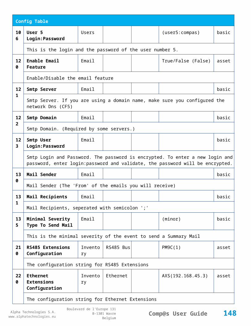
Alpha Technologies S.A.www.alphatechnologies.eu
Alpha Technologies S.A.www.alphatechnologies.eu
Comp@s User GuideBoulevard de l’Europe 131
B-1301 WavreBelgium
Config Table
1
102
Module Start Delay Rectifiers second 0/300 (1) basic
103
Safe Voltage Rectifiers Volt 46/56 (51.4) basic
141
AC Voltage Low Mains Volt basic
The AC voltage under which the alarm AC Low is set.
142
AC Voltage High Mains Volt basic
The AC voltage over which the alarm AC High is set.
143
AC Voltage Hysteresis
Mains Volt basic
The AC voltage hysteresis on alarms AC High and AC Low.
151
Bus Voltage Variable Pointer
Alternate Regulation Pointer Settings
basic
PLC Pointer to variable related to Bus Voltage
152
Battery Temperature Variable Pointer
Alternate Regulation Pointer Settings
basic
PLC Pointer to variable related to Battery Temperature
201
Shunt 1 Rating At 60mV
Adio 1 Shunt 1 Ampere basic
The rating of the shunt 1 at 60mV.
202
Shunt 2 Rating At 60mV
Adio 1 Shunt 2 Ampere basic
The rating of the shunt 2 at 60mV.
204
Digital Input 1 Name Adio 1 Digital Input 1
Adio 1 basic
The name of the digital input 1.
205
Digital Input 1 Normally Closed
Adio 1 Digital Input 1
True/False (True)
basic
True/False value defining if the digital input 1 is normally closed. If this digital input is not in this default
148
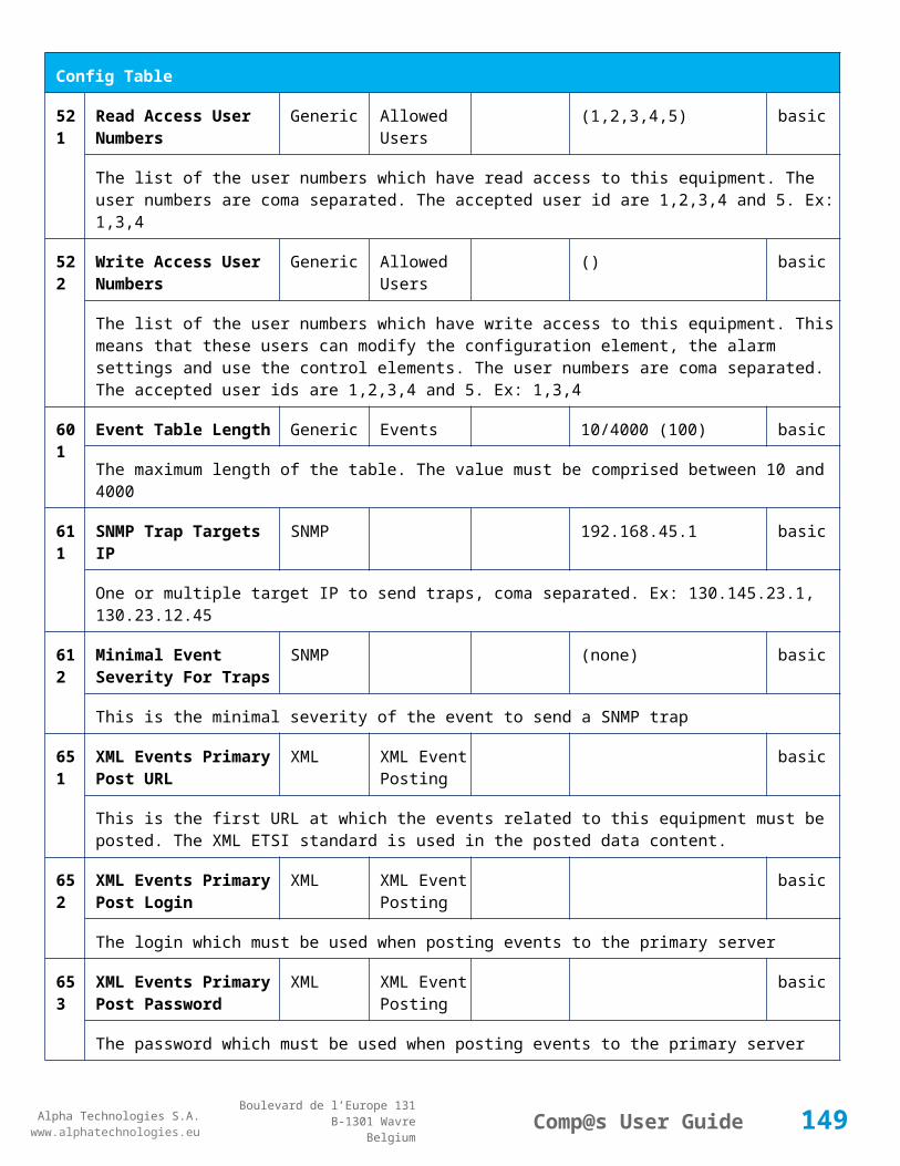
Alpha Technologies S.A.www.alphatechnologies.eu
Alpha Technologies S.A.www.alphatechnologies.eu
Comp@s User GuideBoulevard de l’Europe 131
B-1301 WavreBelgium
Config Table
state, the related alarm is set.
206
Digital Input 2 Name Adio 1 Digital Input 2
Adio 1 basic
The name of the digital input 2.
207
Digital Input 2 Normally Closed
Adio 1 Digital Input 2
True/False (True)
basic
True/False value defining if the digital input 2 is normally closed. If this digital input is not in this default state, the related alarm is set.
208
Digital Input 3 Name Adio 1 Digital Input 3
Adio 1 basic
The name of the digital input 3.
209
Digital Input 3 Normally Closed
Adio 1 Digital Input 3
True/False (True)
basic
True/False value defining if the digital input 3 is normally closed. If this digital input is not in this default state, the related alarm is set.
210
Digital Input 4 Name Adio 1 Digital Input 4
Adio 1 basic
The name of the digital input 4.
211
Digital Input 4 Normally Closed
Adio 1 Digital Input 4
True/False (True)
basic
True/False value defining if the digital input 4 is normally closed. If this digital input is not in this default state, the related alarm is set.
212
Digital Input 5 Name Adio 1 Digital Input 5
Adio 1 basic
The name of the digital input 5.
213
Digital Input 5 Normally Closed
Adio 1 Digital Input 5
True/False (True)
basic
True/False value defining if the digital input 5 is normally closed. If this digital input is not in this default state, the related alarm is set.
214
Digital Input 6 Name Adio 1 Digital Input 6
Adio 1 basic
The name of the digital input 6.
215
Digital Input 6 Normally Closed
Adio 1 Digital Input 6
True/False (True)
basic
149
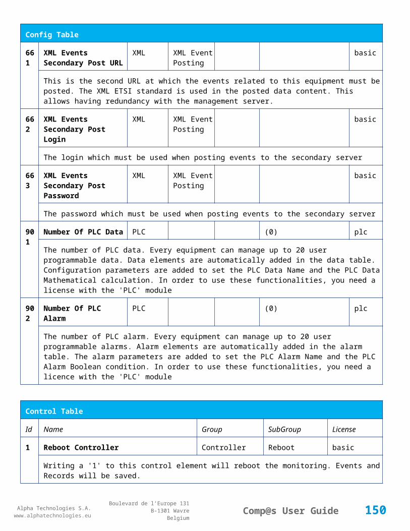
Alpha Technologies S.A.www.alphatechnologies.eu
Alpha Technologies S.A.www.alphatechnologies.eu
Comp@s User GuideBoulevard de l’Europe 131
B-1301 WavreBelgium
Config Table
True/False value defining if the digital input 6 is normally closed. If this digital input is not in this default state, the related alarm is set.
216
Digital Input 7 Name Adio 1 Digital Input 7
Adio 1 basic
The name of the digital input 7.
217
Digital Input 7 Normally Closed
Adio 1 Digital Input 7
True/False (True)
basic
True/False value defining if the digital input 7 is normally closed. If this digital input is not in this default state, the related alarm is set.
218
Digital Input 8 Name Adio 1 Digital Input 8
Adio 1 basic
The name of the digital input 8.
219
Relay 1 Change State Boolan Condition
Adio 1 Relay 1 (False) basic
Relay 1 Boolean Condition
220
Relay 1 Normal State Adio 1 Relay 1 (Energized / De-energized)
basic
Relay 1 Normal State
221
Relay 2 Change State Boolan Condition
Adio 1 Relay 2 (False) basic
Relay 2 Boolean Condition
222
Relay 2 Normal State Adio 1 Relay 2 (Energized / De-energized)
basic
Relay 2 Normal State
223
Relay 3 Change State Boolan Condition
Adio 1 Relay 3 (False) basic
Relay 3 Boolean Condition
224
Relay 3 Normal State Adio 1 Relay 3 (Energized / De-energized)
basic
Relay 3 Normal State
225
Relay 4 Change State Boolan Condition
Adio 1 Relay 4 (False) basic
Relay 4 Boolean Condition
150

Alpha Technologies S.A.www.alphatechnologies.eu
Alpha Technologies S.A.www.alphatechnologies.eu
Comp@s User GuideBoulevard de l’Europe 131
B-1301 WavreBelgium
Config Table
226
Relay 4 Normal State Adio 1 Relay 4 (Energized / De-energized)
basic
Relay 4 Normal State
227
Relay 5 Change State Boolan Condition
Adio 1 Relay 5 (False) basic
Relay 5 Boolean Condition
228
Relay 5 Normal State Adio 1 Relay 5 (Energized / De-energized)
basic
Relay 5 Normal State
229
Relay 6 Change State Boolan Condition
Adio 1 Relay 6 (False) basic
Relay 6 Boolean Condition
230
Relay 6 Normal State Adio 1 Relay 6 (Energized / De-energized)
basic
Relay 6 Normal State
231
Relay 7 Change State Boolan Condition
Adio 1 Relay 7 (False) basic
Relay 7 Boolean Condition
232
Relay 7 Normal State Adio 1 Relay 7 (Energized / De-energized)
basic
Relay 7 Normal State
233
Relay 8 Change State Boolan Condition
Adio 1 Relay 8 (False) basic
Relay 8 Boolean Condition
234
Relay 8 Normal State Adio 1 Relay 8 (Energized / De-energized)
basic
Relay 8 Normal State
235
Default Output Relay Binary Vector
Adio 1 (0b11111111) basic
This configuration is stored inside the module in case of communication failure
521
Read Access User Numbers
Generic Allowed Users
(1,2,3,4,5) basic
The list of the user numbers which have read access to this equipment. The user numbers are coma
151

Alpha Technologies S.A.www.alphatechnologies.eu
Alpha Technologies S.A.www.alphatechnologies.eu
Comp@s User GuideBoulevard de l’Europe 131
B-1301 WavreBelgium
Config Table
separated. The accepted user id are 1,2,3,4 and 5. Ex: 1,3,4
522
Write Access User Numbers
Generic Allowed Users
() basic
The list of the user numbers which have write access to this equipment. This means that these users can modify the configuration element, the alarm settings and use the control elements. The user numbers are coma separated. The accepted user ids are 1,2,3,4 and 5. Ex: 1,3,4
601
Event Table Length Generic Events 10/4000 (100) basic
The maximum length of the table. The value must be comprised between 10 and 4000
602
Event Table Length By Rectifier
Generic Events 10/4000 (100) basic
The maximum length of the table. The value must be comprised between 10 and 4000
901
Number Of PLC Data PLC (0) plc
The number of PLC data. Every equipment can manage up to 20 user programmable data. Data elements are automatically added in the data table. Configuration parameters are added to set the PLC Data Name and the PLC Data Mathematical calculation. In order to use these functionalities, you need a license with the 'PLC' module
902
Number Of PLC Alarm
PLC (0) plc
The number of PLC alarm. Every equipment can manage up to 20 user programmable alarms. Alarm elements are automatically added in the alarm table. The alarm parameters are added to set the PLC Alarm Name and the PLC Alarm Boolean condition. In order to use these functionalities, you need a licence with the 'PLC' module
Control Table
Id Name Group SubGroup License
1 Back To Float DC Mode basic
The dc system must go back in floating mode.
2 Start Battery Test DC Mode battery
The dc system must start a battery test. Il will be canceled if the system is not in float mode or if the number of minutes Since Last Ac Fail End is less than the configured minimum time without mains failure
3 Force Battery Test DC Mode battery
The dc system must force a battery test.
4 Start Equalize Mode DC Mode battery
152

Alpha Technologies S.A.www.alphatechnologies.eu
Alpha Technologies S.A.www.alphatechnologies.eu
Comp@s User GuideBoulevard de l’Europe 131
B-1301 WavreBelgium
Control Table
The dc system must go in equalize mode.
21 Locate Rectifier Clear Locate basic
22 Locate Rectifier On Phase Locate basic
41 Reset Last Battery Test State Battery battery
Reset the state of the last battery test. If an alarm 'Battery Last Test Failed' is set, the alarm will be cleared.
201
Calibrate V1 Adio 1 basic
202
Calibrate V2 Adio 1 basic
203
Calibrate V3 Adio 1 basic
204
Calibrate V4 Adio 1 basic
219
Invert Relay 1 State For X Seconds Adio 1 Relay 1 basic
Generate Pulse on relay
221
Invert Relay 2 State For X Seconds Adio 1 Relay 2 basic
Generate Pulse on relay
223
Invert Relay 3 State For X Seconds Adio 1 Relay 3 basic
Generate Pulse on relay
225
Invert Relay 4 State For X Seconds Adio 1 Relay 4 basic
Generate Pulse on relay
227
Invert Relay 5 State For X Seconds Adio 1 Relay 5 basic
Generate Pulse on relay
229
Invert Relay 6 State For X Seconds Adio 1 Relay 6 basic
Generate Pulse on relay
153
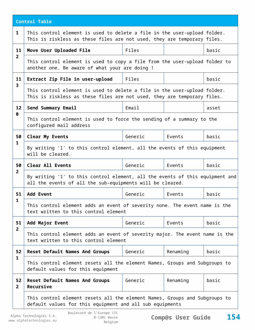
Alpha Technologies S.A.www.alphatechnologies.eu
Alpha Technologies S.A.www.alphatechnologies.eu
Comp@s User GuideBoulevard de l’Europe 131
B-1301 WavreBelgium
Control Table
231
Invert Relay 7 State For X Seconds Adio 1 Relay 7 basic
Generate Pulse on relay
233
Invert Relay 8 State For X Seconds Adio 1 Relay 8 basic
Generate Pulse on relay
501
Clear My Events Generic Events basic
By writing '1' to this control element, all the events of this equipment will be cleared.
502
Clear All Events Generic Events basic
By writing '1' to this control element, all the events of this equipment and all the events of all the sub-equipments will be cleared.
511
Add Event Generic Events basic
This control element adds an event of severity none. The event name is the text written to this control element
512
Add Major Event Generic Events basic
This control element adds an event of severity major. The event name is the text written to this control element
521
Reset Default Names And Groups Generic Renaming basic
This control element resets all the element Names, Groups and Subgroups to default values for this equipment
522
Reset Default Names And Groups Recursive Generic Renaming basic
This control element resets all the element Names, Groups and Subgroups to default values for this equipment and all sub equipments
7.2.2 ADIO 12 AS MCU
Device Information
Name ADIO 12 AS MCU
Short Description ADIO Module used as MCU for hybrid systems
Long Description
Hardware Reference 9413 060 05121
Software Reference SOFT 000121 XX
Equipment Type Monitoring Control Unit
154

Alpha Technologies S.A.www.alphatechnologies.eu
Alpha Technologies S.A.www.alphatechnologies.eu
Comp@s User GuideBoulevard de l’Europe 131
B-1301 WavreBelgium
Device Information
ETSI Level /site/energy_system/dc_system
Description Table
Id Name Group SubGroup License
1 Description Description Custom Description basic
A free text zone to write a system description
2 Reference Description Custom Description basic
A free text zone to write the customer reference of the system
11 Product Name Description Product Info basic
The product name of the DC system monitoring
12 Hardware Reference Description Product Info basic
The hardware reference of the DC system monitoring
14 Software Reference Description Product Info asset
The serial number of the DC system monitoring
16 Serial Number Description Product Info asset
The serial number of the DC system monitoring
18 Manufacturing Date Description Product Info asset
The production date of the DC system monitoring
Alarm Table
Id Name Group SubGroup Severity Type (Level)
Set/Clear Delay
1 DC Bus Extra Low DC Bus major (6) 5 / 2
The bus voltage is extra low. The alarm is set when the bus voltage is lower than the configuration parameter 'DC Bus Voltage Extra Low'. There is an hysteresis on the alarm : 'DC Bus Voltage Extra Low Hysteresis'. The alarm is not activated when DC mode is BATTERY TEST
2 DC Bus Low DC Bus minor (4) 5 / 2
The bus voltage is low. The alarm is set when the bus voltage is lower than the configuration parameter 'DC Bus Voltage Low'. There is an hysteresis on the alarm : 'DC Bus Voltage Low Hysteresis'
155

Alpha Technologies S.A.www.alphatechnologies.eu
Alpha Technologies S.A.www.alphatechnologies.eu
Comp@s User GuideBoulevard de l’Europe 131
B-1301 WavreBelgium
Alarm Table
3 DC Bus High DC Bus minor (4) 5 / 2
The bus voltage is high. The alarm is set when the bus voltage is higher than the configuration paramenter 'DC Bus Voltage High'. There is an hysterisis on the alarm : 'DC Bus Voltage High Hysteresis'
4 DC Bus Extra High DC Bus major (6) 5 / 2
The bus voltage is extra high. The alarm is set when the bus voltage is higher than the configuration paramenter 'DC Bus Voltage Extra High'. There is an hysterisis on the alarm : 'DC Bus Voltage Extra High Hysteresis'
5 DC Bus Voltage Sense Failure
DC Bus major (6) 5 / 2
The DC bus voltage sense is defective. The DC bus voltage is unconnected or unconfigured.
6 Mains Failure AC Bus minor (4) 5 / 2
The number of active rectifiers is equal to 0 and the number of rectifiers in AC failure is greater than 0.
7 Mains Partial Failure AC Bus minor (4) 10 / 2
The number of active rectifiers is greater than 0 and the number of rectifiers in AC failure is greater than 0. Some rectifiers are in AC Failure. It may be caused by an open breaker, a real phase failure, or by a rectifier failure.
8 Mains Low AC Bus warning (2) 10 / 2
The main voltage is low on one or more phases. No rectifier is in AC failure. If MCU master type is 30110, 3096 or 3048M6, an hysteresis _phase123Hysteresis is added to the voltage lower limit
10
One Rectifier Failure Rectifiers minor (4) 5 / 2
One rectifier must be replaced or is not powered correctly. The DC fail alarm of the rectifier is set. The number of rectifier with DC Failure is higher than 0, there is no mains failure, and the 'More Than One Rectifier Failure alarm is not set.'
11
More Than One Rectifier Failure
Rectifiers major (6) 10 / 2
There is no mains failure and number of rectifier failures is greater than 1.
12
Missing Rectifiers Rectifiers major (6) 5 / 2
There is not enough rectifier according to the configuration parameter : 'Minimal Number Of Rectifier'
13
Battery Last Test Failed Battery Battery Test minor (3) 5 / 2
The last battery test did not succeed and was not cancelled. Maybe the battery should be replaced.
14
Battery On Discharge Battery minor (4) 10 / 2
The battery is discharging. This means that the load is too high for the installed rectifiers. This alarm is
156

Alpha Technologies S.A.www.alphatechnologies.eu
Alpha Technologies S.A.www.alphatechnologies.eu
Comp@s User GuideBoulevard de l’Europe 131
B-1301 WavreBelgium
Alarm Table
inactive when the system in AC Failure or during a battery test. There is an hysteresis corresponding to battery parameter 'Is discharging current hysteresis'.
17
Battery LVD Relay Open LVD major (6) 5 / 2
The battery Low Voltage Disconnector is open. On Systems without LVD_Status signal, like MCU 1848 or MCU 1x6, the alarm is present only if the signal LVD_COM asks to open the LVD
18
Battery Temperature Too High
Battery Temperature minor (3) 5 / 2
The temperature of the battery is too high and is greater than -600 units. There is an hysteresis corresponding to battery parameter 'Temperature hysteresis'.
19
Battery Temperature Too Low
Battery Temperature minor (3) 5 / 2
The temperature of the battery is too low and is greater than -600 units. There is an hysteresis corresponding to battery parameter 'Temperature hysteresis'.
20
Battery Temperature Sensor Fail
Battery Temperature minor (3) 5 / 2
The battery temperature sensor (NTC) value is inferior to -500 units meaning that it is not connected or defective.
Data Table
Id Name Group SubGroup Unit License
1 DC Mode System basic
The DC system can have 4 values: 'FLOAT', 'BOOST', 'BATTERY_TEST', 'AC_FAILURE' or SAFE
2 Previous DC Mode System basic
The previous value of the DC Mode
11 Bus Voltage DC Bus Volt basic
The DC bus voltage in volt.
12 Ratio Delivered On Available Power
System % basic
This is the ratio of the delivered power divided by the installed power, in %.
13 Minutes Since Last AC Failure Begin
AC Bus minute basic
The number of minute since the last AC Failure begin
157
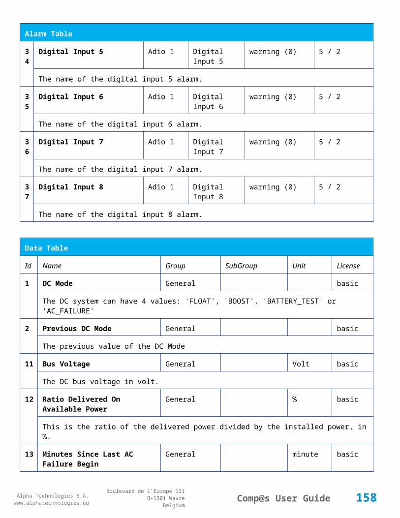
Alpha Technologies S.A.www.alphatechnologies.eu
Alpha Technologies S.A.www.alphatechnologies.eu
Comp@s User GuideBoulevard de l’Europe 131
B-1301 WavreBelgium
Data Table
14 Minutes Since Last AC Failure End
AC Bus minute basic
The number of minute since the last AC Failure end
21 Rectifiers Output Power Rectifiers Watt basic
The sum of the delivered rectifier power
22 Rectifiers Output Current Rectifiers Ampere basic
The sum of the delivered rectifier current
23 Rectifiers Output Power Max Rectifiers Watt basic
The sum of the deliverable rectifier power
24 Rectifiers Output Current Max Rectifiers Ampere basic
The sum of the deliverable rectifier current
31 Number Of Rectifier Max Rectifiers Numbers basic
The maximum possible number of rectifier in this dc system
32 Number Of Present Rectifier Rectifiers Numbers basic
The actual number of present rectifier in this dc system
33 Number Of Absent Rectifier Rectifiers Numbers basic
The actual number of absent rectifier in this dc system
34 Number Of Active Rectifier Rectifiers Numbers basic
The actual number of active rectifier in this dc system. An active rectifier is a rectifier which is present, DC OK, AC OK and not in remote off.
35 Number Of AC-Fail Rectifier Rectifiers Numbers basic
The actual number or rectifier in AC Failure.
36 Number Of DC-Fail Rectifier Rectifiers Numbers basic
The actual number or rectifier with DC Failure.
37 Number Of Remote Off Rectifier Rectifiers Numbers basic
The actual number or rectifier in remote off.
38 Number Of Over Temperature Rectifier
Rectifiers Numbers basic
The actual number or rectifier in OVer Temperature.
158

Alpha Technologies S.A.www.alphatechnologies.eu
Alpha Technologies S.A.www.alphatechnologies.eu
Comp@s User GuideBoulevard de l’Europe 131
B-1301 WavreBelgium
Data Table
51 Load Power Load Watt basic
Estimation of the load power consumption
52 Load Current Load Ampere basic
Estimation of the load current consumption
61 Battery Input Current Battery Ampere basic
Measurement of the battery input current. A negative value means that the battery is discharging
62 Battery Input Power Battery Watt basic
Measurement of the battery input power. A negative value means that the battery is discharging
71 Battery Temperature Battery Temperature degree C basic
The battery temperature
72 Battery Test State Battery Battery Test basic
This is about the result of the last battery test. 9 values are possible : NEVER_TESTED, SUCCESS, ON_GOING, FAILED_TIMEOUT, FAILED_VBUS_TOO_LOW, FAILED_LOAD_TOO_LOW, FAILED_AC_FAILURE, FAILED_CANCELED, FAILED_LVD_OPENED
73 Battery Test Discharged Capacity Ratio
Battery Battery Test % basic
This is the battery capacity, in percent, discharged during the last battery test. This value is updated at the end of the battery test.
74 Battery Test Discharged Capacity Battery Battery Test Ah basic
This is the battery capacity, in ampere hour, discharged during the last battery test. This value is updated at the end of the battery test.
75 Battery Test Final Voltage Battery Battery Test % basic
This is the bus voltage at the end of the last battery test. This value is updated at the end of the battery test.
81 Previous Battery Test State Battery Battery Test basic
The result of the previous battery test
82 Minutes Since Last Test Battery Battery Battery Test basic
The number of minute without battery test
84 Next Scheduled Battery Test Battery Battery Test basic
The date and time of the next time the scheduled battery test will run
159

Alpha Technologies S.A.www.alphatechnologies.eu
Alpha Technologies S.A.www.alphatechnologies.eu
Comp@s User GuideBoulevard de l’Europe 131
B-1301 WavreBelgium
Data Table
91 Battery Charge Capacity Battery % basic
The battery charge capacity, calculated by integration of the current.
92 Calculated Autonomy Battery minute basic
Calculation of the remaining autonomy
93 Battery Current Integration Battery As basic
Actual value of the integration of the current, in Ampere * second
94 Battery Current Integration Battery Ah basic
Actual value of the integration of the current, in Ampere * hour
101
LVD State LVD basic
Actual state of the LVD
111
Relay 1 State Relays Relay 1 basic
Actual state of the Relay 1
112
Relay 2 State Relays Relay 2 basic
Actual state of the Relay 2
113
Relay 3 State Relays Relay 3 basic
Actual state of the Relay 3
114
Relay 4 State Relays Relay 4 basic
Actual state of the Relay 3
121
Efficiency Optimized Number Of Rectifier
Smart Energy asset
The optimal number of ON rectifier for Efficiency Optimization
122
System Loss Without Optimisation
Smart Energy Watt underdev
Estimation of the losses without optimisation
123
System Loss With Optimisation Smart Energy Watt underdev
Estimation of the losses with optimisation
124
Rectifier Model Used For Calculation
Smart Energy asset
The rectifier model used
160

Alpha Technologies S.A.www.alphatechnologies.eu
Alpha Technologies S.A.www.alphatechnologies.eu
Comp@s User GuideBoulevard de l’Europe 131
B-1301 WavreBelgium
Data Table
125
Smart Energy Savings Smart Energy Watt asset
Estimation of the losses with optimisation
161
Voltage 1 Sensors Voltage 1 Volt basic
The voltage measured by the sense 1. Can be used for battery symmetry measurement. Calculation can be done with the PLC
162
Voltage 2 Sensors Voltage 2 Volt basic
The voltage measured by the sense 2. Can be used for battery symmetry measurement. Calculation can be done with the PLC
163
Voltage 3 Sensors Voltage 3 Volt basic
The voltage measured by the sense 3. Can be used for battery symmetry measurement. Calculation can be done with the PLC
211
Battery 1 LVD State Battery Battery 1 basic
212
Battery 2 LVD State Battery Battery 2 basic
213
Battery 3 LVD State Battery Battery 3 basic
214
Battery 4 LVD State Battery Battery 4 basic
221
Battery 1 Current Battery Battery 1 Ampere basic
222
Battery 2 Current Battery Battery 2 Ampere basic
223
Battery 3 Current Battery Battery 3 Ampere basic
224
Battery 4 Current Battery Battery 4 Ampere basic
231
Battery 1 Capacity Battery Battery 1 Ah basic
161

Alpha Technologies S.A.www.alphatechnologies.eu
Alpha Technologies S.A.www.alphatechnologies.eu
Comp@s User GuideBoulevard de l’Europe 131
B-1301 WavreBelgium
Data Table
232
Battery 2 Capacity Battery Battery 2 Ah basic
233
Battery 3 Capacity Battery Battery 3 Ah basic
234
Battery 4 Capacity Battery Battery 4 Ah basic
Config Table
Id Name Group SubGroup Unit Range: Min/Max (default)
License
1 DC Bus Float Voltage at 25 degC
DC Bus Volt 40/60 (54) basic
The floating dc bus voltage of the system at 25 Celsius degree
2 DC Bus Voltage Extra Low
DC Bus Alarm Parameters Volt 40/60 (45) basic
The bus voltage under which the alarm 'DC Bus Voltage Extra Low' is set.
3 DC Bus Voltage Extra Low Hysteresis
DC Bus Alarm Parameters Volt 0/5 (1) basic
The voltage hysteresis on the alarm 'DC Bus Voltage Extra Low'.
4 DC Bus Voltage Low DC Bus Alarm Parameters Volt 40/60 (48) basic
The bus voltage under which the alarm 'DC Bus Voltage Low' is set.
5 DC Bus Voltage Low Hysteresis
DC Bus Alarm Parameters Volt 0/5 (0.5) basic
The voltage hysteresis on the alarm 'DC Bus Voltage Low
6 DC Bus Voltage High DC Bus Alarm Parameters Volt 40/60 (56.5) basic
The bus voltage over which the alarm 'DC Bus Voltage High' is set.
7 DC Bus Voltage High Hysteresis
DC Bus Alarm Parameters Volt 0/5 (0.5) basic
The voltage hysteresis on the alarm 'DC Bus Voltage High
8 DC Bus Voltage Extra DC Bus Alarm Parameters Volt 40/60 (58) basic
162

Alpha Technologies S.A.www.alphatechnologies.eu
Alpha Technologies S.A.www.alphatechnologies.eu
Comp@s User GuideBoulevard de l’Europe 131
B-1301 WavreBelgium
Config Table
High
The bus voltage over which the alarm 'DC Bus Voltage Extra High' is set.
9 DC Bus Voltage Extra High Hysteresis
DC Bus Alarm Parameters Volt 0/5 (0.5) basic
The voltage hysteresis on the alarm 'DC Bus Voltage Extra High
10 LVD Disconnect Voltage LVD Volt 0/50 (43.2) basic
The dc bus voltage under which the battery must be disconnected of the bus. This allows preserving the battery life. The load will be unpowered.
11 LVD Disconnect Delay LVD second 1/2000 (1) basic
The delay in second before disconnecting the battery if the dc bus voltage is under the configured disconnected voltage. This avoids disconnection during a low bus transient.
21 Temperature Compensation Slope
Battery Temperature Compensation
mV/degree -1000/0 (-72) basic
The slope of the battery temperature compensation in mv/degree. For a 48V system, -72mV/degree is often used.
22 Maximum Positive Temperature Compensation
Battery Temperature Compensation
Volt 0/10 (3) basic
The maximal allowed positive compensation.
23 Maximum Negative Temperature Compensation
Battery Temperature Compensation
Volt -10/0 (-3) basic
The maximal allowed negative compensation.
25 Minimal Number Of Present Rectifiers
Rectifiers Alarm Parameters 0/100 (0) basic
The minimal number of rectifier which must be present. If there is less present rectifiers, the alarm 'Missing Rectifiers' is set.
26 Rectifier Model Rectifiers basic
The rectifier model
27 Forced Remote Off Rectifers
Rectifiers basic
A list of rectifier which are forced in remote off. The id of the rectifier must be coma separated. Ex: 1,3 will maintain rectifier 1 and 3 off.
28 Rectifier CAN Node IDs Rectifiers basic
163

Alpha Technologies S.A.www.alphatechnologies.eu
Alpha Technologies S.A.www.alphatechnologies.eu
Comp@s User GuideBoulevard de l’Europe 131
B-1301 WavreBelgium
Config Table
Range
29 Rectifier Ids Declared Rectifiers basic
31 Battery Charge Current Limit
Battery Battery Charge Parameters
Ampere 0.5/1000 (1000) basic
The maximal battery current when the battery is charging. The monitoring regulates the bus voltage in order to satisfy this condition. This parameter is often equal to the nominal battery capacity divided by 10.
32 Battery String Capacity Battery Ah 3/1000 (100) basic
The battery capacity in Ah.
33 Battery Temperature Low
Battery Alarm Parameters degree C -100/20 (0) basic
The temperature under which the alarm 'Battery Temperature Too Low' must be set.
34 Battery Temperature High
Battery Alarm Parameters degree C 5/100 (40) basic
The temperature over which the alarm 'Battery Temperature Too High' must be set.
35 Battery Temperature Hysteresis
Battery Alarm Parameters degree C 0/10 (2) basic
The hysteresis on the 'Battery Temperature Too High' and 'Battery Temperature Too Low' alarms.
36 Minimal Current For Discharging Alarm
Battery Alarm Parameters Ampere 0/1000 (2) basic
The minimal discharging current to set the 'Battery On Discharge' alarm.
37 Current Hysteresis For Discharging Alarm
Battery Alarm Parameters Ampere 0/50 (0.5) basic
The hysteresis on the 'Battery On Discharge' alarm.
40 Number of Battery String
Battery 1-3 basic
The Number of Battery String in the system
51 Boost Automatic Battery Boost False/False (False)
battery
The boost mode must be automatically after the fact that during a mains failure, the bus voltage went under the configured 'Boost Activation Low Voltage'. This allows charging the battery faster.
164
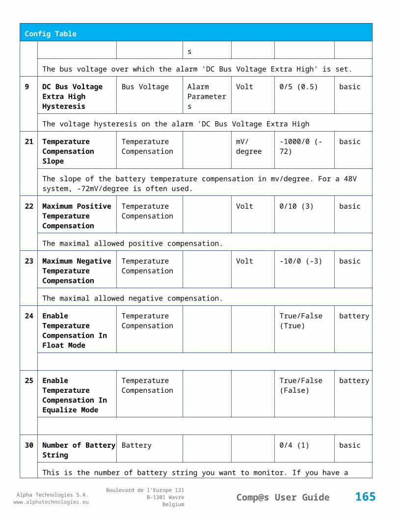
Alpha Technologies S.A.www.alphatechnologies.eu
Alpha Technologies S.A.www.alphatechnologies.eu
Comp@s User GuideBoulevard de l’Europe 131
B-1301 WavreBelgium
Config Table
52 Boost Activation Low Voltage
Battery Boost Volt 43/50 (46) battery
The voltage under which the boost mode can be activated.
53 Boost Termination Voltage
Battery Boost Volt 50/58 (56.4) battery
The voltage over which the system must go back to floating mode.
54 Boost Termination Current
Battery Boost Ampere 0/100 (2) battery
The battery charging current under which the system must go back to floating mode.
55 Boost Termination Time Battery Boost minute 10/240 (120) battery
The time in minute after which the system must go back in floating mode.
70 Battery Test End Voltage
Battery Battery Test Volt 30/60 (46) battery
The voltage at which any battery test must be stopped.
71 Battery Test Discharge Ratio
Battery Battery Test % 0/100 (0) battery
The ratio of the battery capacity to discharge. If 30 is set, 30% of the battery will be discharged during the test
72 Battery Test Interval Battery Battery Test day 0/3000 (0) battery
The number of days between two automatically started battery test. If this parameter is set to 0, the battery test is not started automatically. The user can remotely or locally start or force this test.
73 Battery Test Discharge Current
Battery Battery Test Ampere 3/100 (1000) battery
The current at which the battery must be discharged during a battery test. The monitoring regulates the bus voltage in order to satisfy this condition. The load current must be of course higher than this parameter.
74 Battery Test Minimal Discharge Current
Battery Battery Test Ampere 2/90 (2) battery
The battery current under which the battery test must be stopped because the load is too low.
75 Battery Test Time Out Battery Battery Test minute 1/5000 (10) battery
The timeout in minute after which the battery test must be stopped.
76 Battery Test Requested Minutes Without Mains Failure
Battery Battery Test minute 0/5000 (1440) battery
165
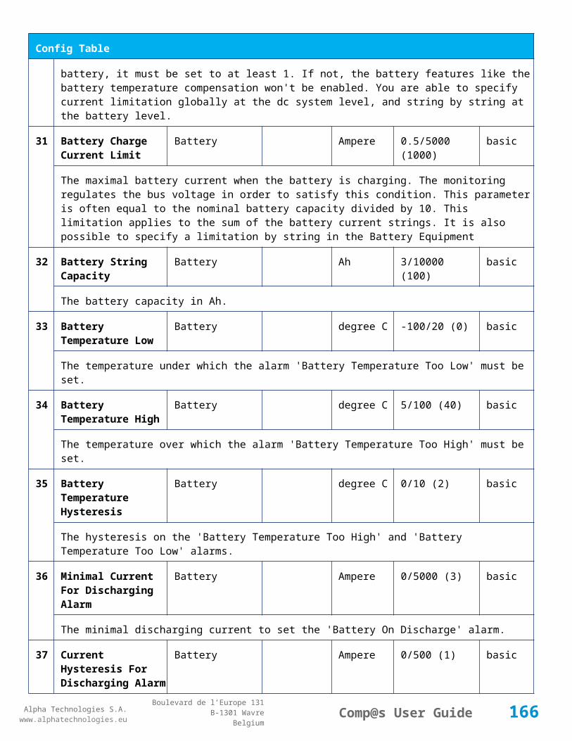
Alpha Technologies S.A.www.alphatechnologies.eu
Alpha Technologies S.A.www.alphatechnologies.eu
Comp@s User GuideBoulevard de l’Europe 131
B-1301 WavreBelgium
Config Table
The minimal time in minute without mains failure in order to allow a battery start. This parameter is not taken into account when the battery test is forced.
77 Battery Test Scheduler Cron Rule
Battery Battery Test basic
83 Smart Energy Boolean Condition
Smart Energy
asset
This is the boolean condition which allows or not to automatically optimize the number of rectifier in remote off.
86 Battery LVD Node Id LVD True/False (False)
basic
This is a list of the node id of the Smart Electronic LVDs, coma separated
111
Dry Alarm 1 Alternative Boolean Condition
Relays Relay 1 plc
Another Boolean condition to activate the dry alarm relay 1. The way to define boolean condition is detailed in the PLC chapter.
112
Dry Alarm 2 Alternative Boolean Condition
Relays Relay 2 plc
Another Boolean condition to activate the dry alarm relay 2. The way to define boolean condition is detailed in the PLC chapter.
113
Dry Alarm 3 Alternative Boolean Condition
Relays Relay 3 plc
Another Boolean condition to activate the dry alarm relay 3. The way to define boolean condition is detailed in the PLC chapter.
114
Dry Alarm 4 Alternative Boolean Condition
Relays Relay 4 plc
Another Boolean condition to activate the dry alarm relay 4. The way to define boolean condition is detailed in the PLC chapter.
521
Read Access User Numbers
Generic Allowed Users (1,2,3,4,5) basic
The list of the user numbers which have read access to this equipment. The user numbers are coma separated. The accepted user id are 1,2,3,4 and 5. Ex: 1,3,4
522
Write Access User Numbers
Generic Allowed Users () basic
The list of the user numbers which have write access to this equipment. This means that these users can modify the configuration element, the alarm settings and use the control elements. The user
166

Alpha Technologies S.A.www.alphatechnologies.eu
Alpha Technologies S.A.www.alphatechnologies.eu
Comp@s User GuideBoulevard de l’Europe 131
B-1301 WavreBelgium
Config Table
numbers are coma separated. The accepted user ids are 1,2,3,4 and 5. Ex: 1,3,4
601
Event Table Length Generic Events 10/4000 (100) basic
The maximum length of the table. The value must be comprised between 10 and 4000
602
Event Table Length By Rectifier
Generic Events 10/4000 (100) basic
The maximum length of the table. The value must be comprised between 10 and 4000
901
Number Of PLC Data PLC (0) plc
The number of PLC data. Every equipment can manage up to 20 user programmable data. Data elements are automatically added in the data table. Configuration parameters are added to set the PLC Data Name and the PLC Data Mathematical calculation. In order to use these functionalities, you need a license with the 'PLC' module
902
Number Of PLC Alarm PLC (0) plc
The number of PLC alarm. Every equipment can manage up to 20 user programmable alarms. Alarm elements are automatically added in the alarm table. The alarm parameters are added to set the PLC Alarm Name and the PLC Alarm Boolean condition. In order to use these functionalities, you need a licence with the 'PLC' module
Control Table
Id Name Group SubGroup License
1 Back To Float System basic
The dc system must go back in floating mode.
2 Start Battery Test System battery
The dc system must start a battery test.
3 Force Battery Test System battery
The dc system must force a battery test.
4 Start Boost Mode System battery
The dc system must go in boost mode.
11 Open The LVD LVD basic
Try to open the LVD. It could not work if the LVD is electronic, and the request will be canceled after 15 sec.
12 Close The LVD LVD basic
167

Alpha Technologies S.A.www.alphatechnologies.eu
Alpha Technologies S.A.www.alphatechnologies.eu
Comp@s User GuideBoulevard de l’Europe 131
B-1301 WavreBelgium
Control Table
The LVD must be closed
21 Correct Battery Current Offset Battery basic
31 Reset Battery Current Integration Battery basic
Reset the integration of the battery current.
41 Reset Last Battery Test State Battery battery
Reset the state of the last battery test. If an alarm 'Battery Last Test Failed' is set, the alarm will be cleared.
51 Save Configuration In MCU Save basic
Save configuration parameters in the MCU microcontroller. If comp@s is not present, the system will be correctly managed.
55 Set MCU Specific Configuration Id Advanced Factory basic
This control allows to reconfigure the MCU to support specific hardware configuration, with embedded distribution for example
61 Set Digital Input 4 Counter Value Digital Inputs Digital Input 4 basic
Set Counter Value
111
Invert Relay 1 State For X Seconds Relays Relay 1 basic
Generate Pulse on relay 1
112
Invert Relay 2 State For X Seconds Relays Relay 2 basic
Generate Pulse on relay 2
113
Invert Relay 3 State For X Seconds Relays Relay 3 basic
Generate Pulse on relay 3
114
Invert Relay 4 State For X Seconds Relays Relay 4 basic
Generate Pulse on relay 4
501
Clear My Events Generic Events basic
By writing '1' to this control element, all the events of this equipment will be cleared.
502
Clear All Events Generic Events basic
By writing '1' to this control element, all the events of this equipment and all the events of all the sub-equipments will be cleared.
168

Alpha Technologies S.A.www.alphatechnologies.eu
Alpha Technologies S.A.www.alphatechnologies.eu
Comp@s User GuideBoulevard de l’Europe 131
B-1301 WavreBelgium
Control Table
511
Add Event Generic Events basic
This control element adds an event of severity none. The event name is the text written to this control element
512
Add Major Event Generic Events basic
This control element adds an event of severity major. The event name is the text written to this control element
521
Reset Default Names And Groups Generic Renaming basic
This control element resets all the element Names, Groups and Subgroups to default values for this equipment
522
Reset Default Names And Groups Recursive Generic Renaming basic
This control element resets all the element Names, Groups and Subgroups to default values for this equipment and all sub equipments
7.2.3 MCU1X6
Device Information
Name MCU1X6
Short Description Controller without LCD display
Long Description Monitoring and control unit with USB and Ethernet port - ACE186 and ACE106 (+24V) lines
Hardware Reference
9413 060 10121
Software Reference
SOFT 000069 XX
Equipment Type Monitoring Control Unit
ETSI Level /site/energy_system/dc_system
Description Table
Id Name Group SubGroup License
1 Description Description Custom Description basic
A free text zone to write a system description
2 Reference Description Custom Description basic
169

Alpha Technologies S.A.www.alphatechnologies.eu
Alpha Technologies S.A.www.alphatechnologies.eu
Comp@s User GuideBoulevard de l’Europe 131
B-1301 WavreBelgium
Description Table
A free text zone to write the customer reference of the system
11 Product Name Description Product Info basic
The product name of the DC system monitoring
12 Hardware Reference Description Product Info basic
The hardware reference of the DC system monitoring
14 Software Reference Description Product Info asset
The serial number of the DC system monitoring
16 Serial Number Description Product Info asset
The serial number of the DC system monitoring
18 Manufacturing Date Description Product Info asset
The production date of the DC system monitoring
Alarm Table
Id Name Group SubGroup Severity Type (Level)
Set/Clear Delay
1 DC Bus Extra Low DC Bus major (6) 5 / 2
The bus voltage is extra low. The alarm is set when the bus voltage is lower than the configuration parameter 'DC Bus Voltage Extra Low'. There is an hysteresis on the alarm : 'DC Bus Voltage Extra Low Hysteresis'. The alarm is not activated when DC mode is BATTERY TEST
2 DC Bus Low DC Bus minor (4) 5 / 2
The bus voltage is low. The alarm is set when the bus voltage is lower than the configuration parameter 'DC Bus Voltage Low'. There is an hysteresis on the alarm : 'DC Bus Voltage Low Hysteresis'
3 DC Bus High DC Bus minor (4) 5 / 2
The bus voltage is high. The alarm is set when the bus voltage is higher than the configuration paramenter 'DC Bus Voltage High'. There is an hysterisis on the alarm : 'DC Bus Voltage High Hysteresis'
4 DC Bus Extra High DC Bus major (6) 5 / 2
The bus voltage is extra high. The alarm is set when the bus voltage is higher than the configuration paramenter 'DC Bus Voltage Extra High'. There is an hysterisis on the alarm : 'DC Bus Voltage Extra High Hysteresis'
5 DC Bus Voltage Sense Failure
DC Bus major (6) 5 / 2
170

Alpha Technologies S.A.www.alphatechnologies.eu
Alpha Technologies S.A.www.alphatechnologies.eu
Comp@s User GuideBoulevard de l’Europe 131
B-1301 WavreBelgium
Alarm Table
The DC bus voltage sense is defective. The DC bus voltage is unconnected or unconfigured.
6 Mains Failure AC Bus minor (4) 5 / 2
The number of active rectifiers is equal to 0 and the number of rectifiers in AC failure is greater than 0.
7 Mains Partial Failure AC Bus minor (4) 10 / 2
The number of active rectifiers is greater than 0 and the number of rectifiers in AC failure is greater than 0. Some rectifiers are in AC Failure. It may be caused by an open breaker, a real phase failure, or by a rectifier failure.
8 Mains Low AC Bus warning (2) 10 / 2
The main voltage is low on one or more phases. No rectifier is in AC failure. If MCU master type is 30110, 3096 or 3048M6, an hysteresis _phase123Hysteresis is added to the voltage lower limit
10
One Rectifier Failure Rectifiers minor (4) 5 / 2
One rectifier must be replaced or is not powered correctly. The DC fail alarm of the rectifier is set. The number of rectifier with DC Failure is higher than 0, there is no mains failure, and the 'More Than One Rectifier Failure alarm is not set.'
11
More Than One Rectifier Failure
Rectifiers major (6) 10 / 2
There is no mains failure and number of rectifier failures is greater than 1.
12
Missing Rectifiers Rectifiers major (6) 5 / 2
There is not enough rectifier according to the configuration parameter : 'Minimal Number Of Rectifier'
13
Battery Last Test Failed Battery Battery Test minor (3) 5 / 2
The last battery test did not succeed and was not cancelled. Maybe the battery should be replaced.
14
Battery On Discharge Battery minor (4) 10 / 2
The battery is discharging. This means that the load is too high for the installed rectifiers. This alarm is inactive when the system in AC Failure or during a battery test. There is an hysteresis corresponding to battery parameter 'Is discharging current hysteresis'.
17
Battery LVD Relay Open LVD major (6) 5 / 2
The battery Low Voltage Disconnector is open. On Systems without LVD_Status signal, like MCU 1848 or MCU 1x6, the alarm is present only if the signal LVD_COM asks to open the LVD
18
Battery Temperature Too High
Battery Temperature minor (3) 5 / 2
The temperature of the battery is too high and is greater than -600 units. There is an hysteresis corresponding to battery parameter 'Temperature hysteresis'.
1 Battery Temperature Too Battery Temperature minor (3) 5 / 2
171

Alpha Technologies S.A.www.alphatechnologies.eu
Alpha Technologies S.A.www.alphatechnologies.eu
Comp@s User GuideBoulevard de l’Europe 131
B-1301 WavreBelgium
Alarm Table
9 Low
The temperature of the battery is too low and is greater than -600 units. There is an hysteresis corresponding to battery parameter 'Temperature hysteresis'.
20
Battery Temperature Sensor Fail
Battery Temperature minor (3) 5 / 2
The battery temperature sensor (NTC) value is inferior to -500 units meaning that it is not connected or defective.
21
Ambient Temperature Too High
Sensors Temperature minor (0) 5 / 2
The ambient temperature is too high and is greater than -600 units. There is an hysteresis corresponding to parameter 'Ambiant temperature hysteresis'. This alarm is only activated on MCU master types 30110, 3096, 30125, 0024, 0948, 0548, 0348, 0948 and 3048M6.
22
Ambient Temperature Too Low
Sensors Temperature minor (0) 5 / 2
The ambient temperature is too low and is greater than -600 units. There is an hysteresis corresponding to parameter 'Ambiant temperature hysteresis'. This alarm is only activated on MCU master types 30110, 3096, 30125, 0024, 0948, 0548, 0348, 0948 and 3048M6.
23
Ambient Temperature Sensor Fail
Sensors Temperature minor (0) 5 / 2
The ambiant temperature sensor (NTC) value is inferior to -500 units meaning that it is not connected or defective.
25
Distribution Breaker Open Digital Inputs major (6) 5 / 2
This alarm is related to digital input 1. This alarm is activated if digital input value is different to configuration parameter 'Digital Input Alarm Value'
26
Battery Breaker Open Digital Inputs minor (4) 5 / 2
This alarm is related to digital input 2. This alarm is activated if digital input value is different to configuration parameter 'Digital Input Alarm Value'
27
Digital Input 3 Digital Inputs none (0) 5 / 2
This alarm is related to digital input 3. This alarm is activated if digital input value is different to configuration parameter 'Digital Input Alarm Value'
28
Digital Input 4 Digital Inputs none (0) 5 / 2
This alarm is related to digital input 4. This alarm is activated if digital input value is different to configuration parameter 'Digital Input Alarm Value'
29
Digital Input 5 Digital Inputs disabled (0) 5 / 2
This alarm is related to digital input 5. This alarm is activated if digital input value is different to
172

Alpha Technologies S.A.www.alphatechnologies.eu
Alpha Technologies S.A.www.alphatechnologies.eu
Comp@s User GuideBoulevard de l’Europe 131
B-1301 WavreBelgium
Alarm Table
configuration parameter 'Digital Input Alarm Value'
30
Digital Input 6 Digital Inputs disabled (0) 5 / 2
This alarm is related to digital input 6. This alarm is activated if digital input value is different to configuration parameter 'Digital Input Alarm Value'
31
Digital Input 7 Digital Inputs disabled (0) 5 / 2
This alarm is related to digital input 7. This alarm is activated if digital input value is different to configuration parameter 'Digital Input Alarm Value'
32
Digital Input 8 Digital Inputs disabled (0) 5 / 2
This alarm is related to digital input 8. This alarm is activated if digital input value is different to configuration parameter 'Digital Input Alarm Value'
Data Table
Id Name Group SubGroup Unit License
1 DC Mode System basic
The DC system can have 4 values: 'FLOAT', 'BOOST', 'BATTERY_TEST', 'AC_FAILURE' or SAFE
2 Previous DC Mode System basic
The previous value of the DC Mode
11 Bus Voltage DC Bus Volt basic
The DC bus voltage in volt.
12 Ratio Delivered On Available Power
System % basic
This is the ratio of the delivered power divided by the installed power, in %.
13 Minutes Since Last AC Failure Begin
AC Bus minute basic
The number of minute since the last AC Failure begin
14 Minutes Since Last AC Failure End
AC Bus minute basic
The number of minute since the last AC Failure end
21 Rectifiers Output Power Rectifiers Watt basic
The sum of the delivered rectifier power
173
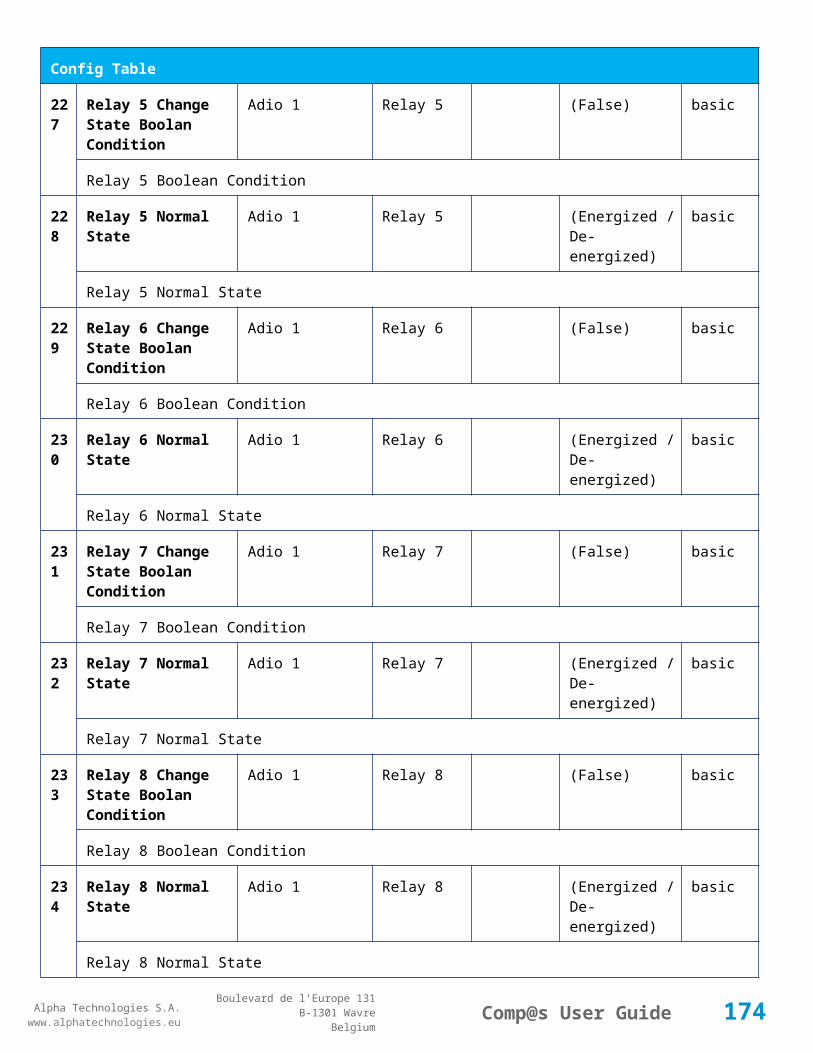
Alpha Technologies S.A.www.alphatechnologies.eu
Alpha Technologies S.A.www.alphatechnologies.eu
Comp@s User GuideBoulevard de l’Europe 131
B-1301 WavreBelgium
Data Table
22 Rectifiers Output Current Rectifiers Ampere basic
The sum of the delivered rectifier current
23 Rectifiers Output Power Max Rectifiers Watt basic
The sum of the deliverable rectifier power
24 Rectifiers Output Current Max Rectifiers Ampere basic
The sum of the deliverable rectifier current
31 Number Of Rectifier Max Rectifiers Numbers basic
The maximum possible number of rectifier in this dc system
32 Number Of Present Rectifier Rectifiers Numbers basic
The actual number of present rectifier in this dc system
33 Number Of Absent Rectifier Rectifiers Numbers basic
The actual number of absent rectifier in this dc system
34 Number Of Active Rectifier Rectifiers Numbers basic
The actual number of active rectifier in this dc system. An active rectifier is a rectifier which is present, DC OK, AC OK and not in remote off.
35 Number Of AC-Fail Rectifier Rectifiers Numbers basic
The actual number or rectifier in AC Failure.
36 Number Of DC-Fail Rectifier Rectifiers Numbers basic
The actual number or rectifier with DC Failure.
37 Number Of Remote Off Rectifier Rectifiers Numbers basic
The actual number or rectifier in remote off.
38 Number Of Over Temperature Rectifier
Rectifiers Numbers basic
The actual number or rectifier in OVer Temperature.
51 Load Power Load Watt basic
Estimation of the load power consumption
52 Load Current Load Ampere basic
Estimation of the load current consumption
174

Alpha Technologies S.A.www.alphatechnologies.eu
Alpha Technologies S.A.www.alphatechnologies.eu
Comp@s User GuideBoulevard de l’Europe 131
B-1301 WavreBelgium
Data Table
61 Battery Input Current Battery Ampere basic
Measurement of the battery input current. A negative value means that the battery is discharging
62 Battery Input Power Battery Watt basic
Measurement of the battery input power. A negative value means that the battery is discharging
71 Battery Temperature Battery Temperature degree C basic
The battery temperature
72 Battery Test State Battery Battery Test basic
This is about the result of the last battery test. 9 values are possible : NEVER_TESTED, SUCCESS, ON_GOING, FAILED_TIMEOUT, FAILED_VBUS_TOO_LOW, FAILED_LOAD_TOO_LOW, FAILED_AC_FAILURE, FAILED_CANCELED, FAILED_LVD_OPENED
73 Battery Test Discharged Capacity Ratio
Battery Battery Test % basic
This is the battery capacity, in percent, discharged during the last battery test. This value is updated at the end of the battery test.
74 Battery Test Discharged Capacity
Battery Battery Test Ah basic
This is the battery capacity, in ampere hour, discharged during the last battery test. This value is updated at the end of the battery test.
75 Battery Test Final Voltage Battery Battery Test % basic
This is the bus voltage at the end of the last battery test. This value is updated at the end of the battery test.
81 Previous Battery Test State Battery Battery Test basic
The result of the previous battery test
82 Minutes Since Last Test Battery Battery Battery Test basic
The number of minute without battery test
84 Next Scheduled Battery Test Battery Battery Test basic
The date and time of the next time the scheduled battery test will run
91 Battery Charge Capacity Battery % basic
The battery charge capacity, calculated by integration of the current.
92 Calculated Autonomy Battery minute basic
Calculation of the remaining autonomy
175

Alpha Technologies S.A.www.alphatechnologies.eu
Alpha Technologies S.A.www.alphatechnologies.eu
Comp@s User GuideBoulevard de l’Europe 131
B-1301 WavreBelgium
Data Table
93 Battery Current Integration Battery As basic
Actual value of the integration of the current, in Ampere * second
94 Battery Current Integration Battery Ah basic
Actual value of the integration of the current, in Ampere * hour
101
LVD State LVD basic
Actual state of the LVD
111
Relay 1 State Relays Relay 1 basic
Actual state of the Relay 1
112
Relay 2 State Relays Relay 2 basic
Actual state of the Relay 2
113
Relay 3 State Relays Relay 3 basic
Actual state of the Relay 3
114
Relay 4 State Relays Relay 4 basic
Actual state of the Relay 3
121
Efficiency Optimized Number Of Rectifier
Smart Energy asset
The optimal number of ON rectifier for Efficiency Optimization
122
System Loss Without Optimisation
Smart Energy Watt underdev
Estimation of the losses without optimisation
123
System Loss With Optimisation Smart Energy Watt underdev
Estimation of the losses with optimisation
124
Rectifier Model Used For Calculation
Smart Energy asset
The rectifier model used
125
Smart Energy Savings Smart Energy Watt asset
Estimation of the losses with optimisation
151
Ambient Temperature Sensors Temperature degree C basic
The ambiant temperature (second temperature sense)
176
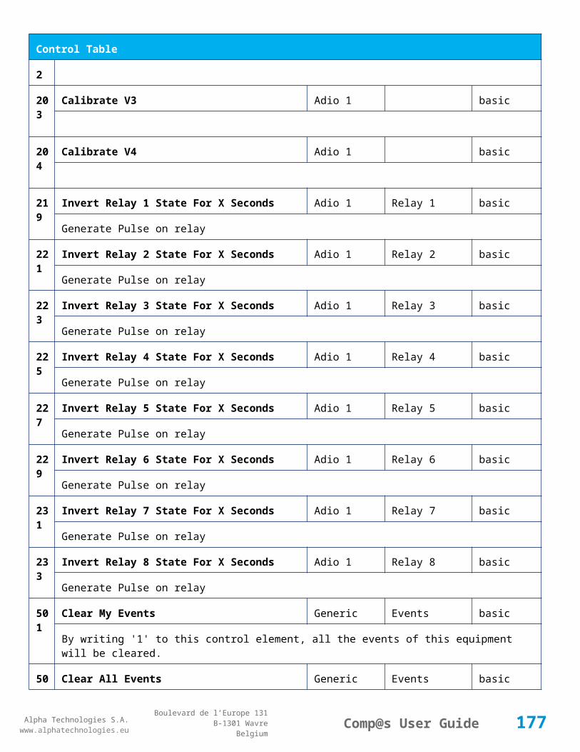
Alpha Technologies S.A.www.alphatechnologies.eu
Alpha Technologies S.A.www.alphatechnologies.eu
Comp@s User GuideBoulevard de l’Europe 131
B-1301 WavreBelgium
Data Table
161
Voltage 1 Sensors Voltage 1 Volt basic
The voltage measured by the sense 1. Can be used for battery symmetry measurement. Calculation can be done with the PLC
162
Voltage 2 Sensors Voltage 2 Volt basic
The voltage measured by the sense 2. Can be used for battery symmetry measurement. Calculation can be done with the PLC
163
Voltage 3 Sensors Voltage 3 Volt basic
The voltage measured by the sense 3. Can be used for battery symmetry measurement. Calculation can be done with the PLC
204
Pulse Counter 4 Sensors Pulse Counter 4 basic
The counter value of the digital input 4.
Config Table
Id Name Group SubGroup Unit Range: Min/Max (default)
License
1 DC Bus Float Voltage at 25 degC
DC Bus Volt 40/60 (54) basic
The floating dc bus voltage of the system at 25 Celsius degree
2 DC Bus Voltage Extra Low
DC Bus Alarm Parameters Volt 40/60 (45) basic
The bus voltage under which the alarm 'DC Bus Voltage Extra Low' is set.
3 DC Bus Voltage Extra Low Hysteresis
DC Bus Alarm Parameters Volt 0/5 (1) basic
The voltage hysteresis on the alarm 'DC Bus Voltage Extra Low'.
4 DC Bus Voltage Low DC Bus Alarm Parameters Volt 40/60 (48) basic
The bus voltage under which the alarm 'DC Bus Voltage Low' is set.
5 DC Bus Voltage Low Hysteresis
DC Bus Alarm Parameters Volt 0/5 (0.5) basic
The voltage hysteresis on the alarm 'DC Bus Voltage Low
6 DC Bus Voltage High DC Bus Alarm Parameters Volt 40/60 (56.5) basic
The bus voltage over which the alarm 'DC Bus Voltage High' is set.
177
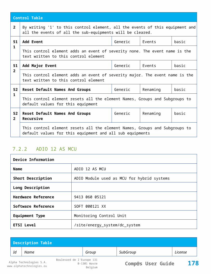
Alpha Technologies S.A.www.alphatechnologies.eu
Alpha Technologies S.A.www.alphatechnologies.eu
Comp@s User GuideBoulevard de l’Europe 131
B-1301 WavreBelgium
Config Table
7 DC Bus Voltage High Hysteresis
DC Bus Alarm Parameters Volt 0/5 (0.5) basic
The voltage hysteresis on the alarm 'DC Bus Voltage High
8 DC Bus Voltage Extra High
DC Bus Alarm Parameters Volt 40/60 (58) basic
The bus voltage over which the alarm 'DC Bus Voltage Extra High' is set.
9 DC Bus Voltage Extra High Hysteresis
DC Bus Alarm Parameters Volt 0/5 (0.5) basic
The voltage hysteresis on the alarm 'DC Bus Voltage Extra High
10 LVD Disconnect Voltage LVD Volt 0/50 (43.2) basic
The dc bus voltage under which the battery must be disconnected of the bus. This allows preserving the battery life. The load will be unpowered.
11 LVD Disconnect Delay LVD second 1/2000 (1) basic
The delay in second before disconnecting the battery if the dc bus voltage is under the configured disconnected voltage. This avoids disconnection during a low bus transient.
21 Temperature Compensation Slope
Battery Temperature Compensation
mV/degree -1000/0 (-72) basic
The slope of the battery temperature compensation in mv/degree. For a 48V system, -72mV/degree is often used.
22 Maximum Positive Temperature Compensation
Battery Temperature Compensation
Volt 0/10 (3) basic
The maximal allowed positive compensation.
23 Maximum Negative Temperature Compensation
Battery Temperature Compensation
Volt -10/0 (-3) basic
The maximal allowed negative compensation.
25 Minimal Number Of Present Rectifiers
Rectifiers Alarm Parameters 0/100 (0) basic
The minimal number of rectifier which must be present. If there is less present rectifiers, the alarm 'Missing Rectifiers' is set.
26 Rectifier Model Rectifiers basic
The rectifier model
27 Forced Remote Off Rectifiers basic
178
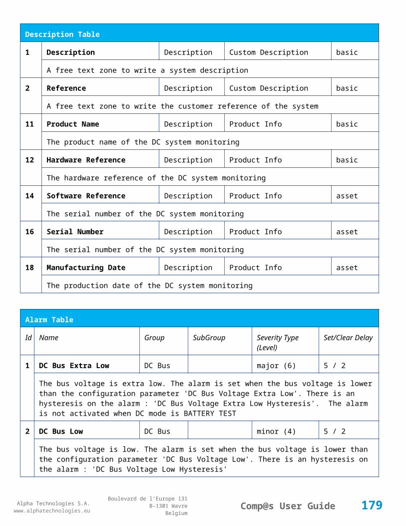
Alpha Technologies S.A.www.alphatechnologies.eu
Alpha Technologies S.A.www.alphatechnologies.eu
Comp@s User GuideBoulevard de l’Europe 131
B-1301 WavreBelgium
Config Table
Rectifers
A list of rectifier which are forced in remote off. The id of the rectifier must be coma separated. Ex: 1,3 will maintain rectifier 1 and 3 off.
31 Battery Charge Current Limit
Battery Battery Charge Parameters
Ampere 0.5/1000 (1000) basic
The maximal battery current when the battery is charging. The monitoring regulates the bus voltage in order to satisfy this condition. This parameter is often equal to the nominal battery capacity divided by 10.
32 Battery String Capacity Battery Ah 3/1000 (100) basic
The battery capacity in Ah.
33 Battery Temperature Low
Battery Alarm Parameters degree C -100/20 (0) basic
The temperature under which the alarm 'Battery Temperature Too Low' must be set.
34 Battery Temperature High
Battery Alarm Parameters degree C 5/100 (40) basic
The temperature over which the alarm 'Battery Temperature Too High' must be set.
35 Battery Temperature Hysteresis
Battery Alarm Parameters degree C 0/10 (2) basic
The hysteresis on the 'Battery Temperature Too High' and 'Battery Temperature Too Low' alarms.
36 Minimal Current For Discharging Alarm
Battery Alarm Parameters Ampere 0/1000 (3) basic
The minimal discharging current to set the 'Battery On Discharge' alarm.
37 Current Hysteresis For Discharging Alarm
Battery Alarm Parameters Ampere 0/50 (1) basic
The hysteresis on the 'Battery On Discharge' alarm.
41 Shunt Rating At 60mV Current Sensors
Shunt 1 Ampere 25/5000 (250) basic
The rating of the battery shunt at 60mV.
51 Boost Automatic Battery Boost False/False (False)
battery
The boost mode must be automatically after the fact that during a mains failure, the bus voltage went under the configured 'Boost Activation Low Voltage'. This allows charging the battery faster.
52 Boost Activation Low Voltage
Battery Boost Volt 43/50 (46) battery
179
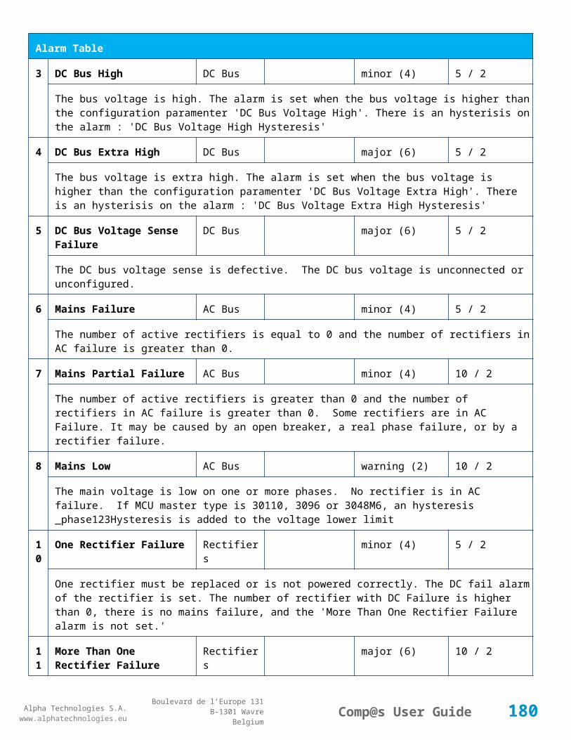
Alpha Technologies S.A.www.alphatechnologies.eu
Alpha Technologies S.A.www.alphatechnologies.eu
Comp@s User GuideBoulevard de l’Europe 131
B-1301 WavreBelgium
Config Table
The voltage under which the boost mode can be activated.
53 Boost Termination Voltage
Battery Boost Volt 50/58 (56.4) battery
The voltage over which the system must go back to floating mode.
54 Boost Termination Current
Battery Boost Ampere 0/100 (4) battery
The battery charging current under which the system must go back to floating mode.
55 Boost Termination Time Battery Boost minute 10/240 (120) battery
The time in minute after which the system must go back in floating mode.
70 Battery Test End Voltage
Battery Battery Test Volt 30/60 (46) battery
The voltage at which any battery test must be stopped.
71 Battery Test Discharge Ratio
Battery Battery Test % 0/100 (0) battery
The ratio of the battery capacity to discharge. If 30 is set, 30% of the battery will be discharged during the test
72 Battery Test Interval Battery Battery Test day 0/3000 (0) battery
The number of days between two automatically started battery test. If this parameter is set to 0, the battery test is not started automatically. The user can remotely or locally start or force this test.
73 Battery Test Discharge Current
Battery Battery Test Ampere 3/100 (1000) battery
The current at which the battery must be discharged during a battery test. The monitoring regulates the bus voltage in order to satisfy this condition. The load current must be of course higher than this parameter.
74 Battery Test Minimal Discharge Current
Battery Battery Test Ampere 2/90 (2) battery
The battery current under which the battery test must be stopped because the load is too low.
75 Battery Test Time Out Battery Battery Test minute 1/5000 (10) battery
The timeout in minute after which the battery test must be stopped.
76 Battery Test Requested Minutes Without Mains Failure
Battery Battery Test minute 0/5000 (1440) battery
The minimal time in minute without mains failure in order to allow a battery start. This parameter is not taken into account when the battery test is forced.
180
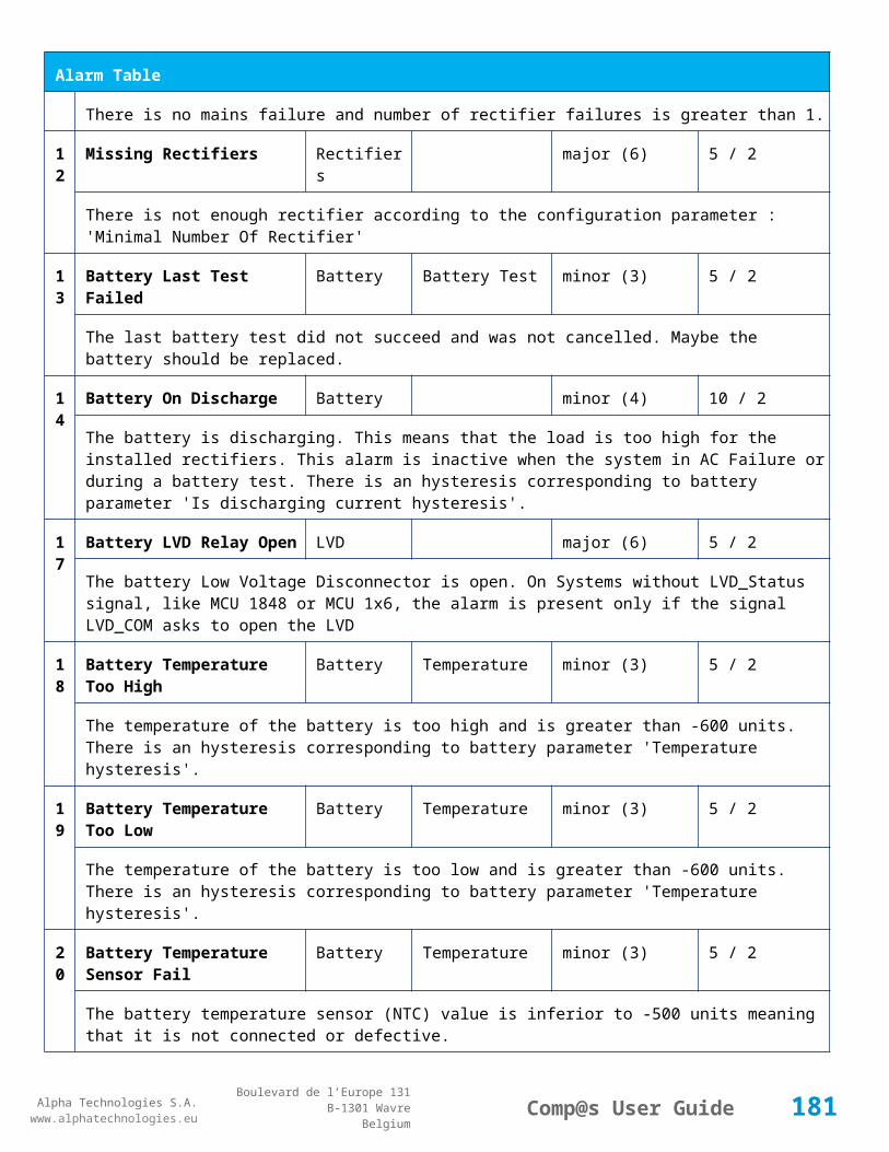
Alpha Technologies S.A.www.alphatechnologies.eu
Alpha Technologies S.A.www.alphatechnologies.eu
Comp@s User GuideBoulevard de l’Europe 131
B-1301 WavreBelgium
Config Table
77 Battery Test Scheduler Cron Rule
Battery Battery Test basic
83 Smart Energy Boolean Condition
Smart Energy
asset
This is the boolean condition which allows or not to automatically optimize the number of rectifier in remote off.
86 Battery LVD Node Id LVD True/False (False)
basic
This is a list of the node id of the Smart Electronic LVDs, coma separated
91 Digital Input 1 Name Digital Inputs
Digital Input 1 Distribution Breaker Open
basic
The name of the digital input 1
92 Digital Input 1 Normally Closed
Digital Inputs
Digital Input 1 True/False (True)
basic
True/False value defining if the digital input 1 is normally closed. If this digital input is not in this default state, the related alarm is set.
93 Digital Input 2 Name Digital Inputs
Digital Input 2 Battery Breaker Open
basic
The name of the digital input 2
94 Digital Input 2 Normally Closed
Digital Inputs
Digital Input 2 True/False (True)
basic
True/False value defining if the digital input 2 is normally closed. If this digital input is not in this default state, the related alarm is set.
95 Digital Input 3 Name Digital Inputs
Digital Input 3 Digital Input 3 basic
The name of the digital input 3
96 Digital Input 3 Normally Closed
Digital Inputs
Digital Input 3 True/False (True)
basic
True/False value defining if the digital input 3 is normally closed. If this digital input is not in this default state, the related alarm is set.
97 Digital Input 4 Name Digital Inputs
Digital Input 4 Digital Input 4 basic
The name of the digital input 4
181

Alpha Technologies S.A.www.alphatechnologies.eu
Alpha Technologies S.A.www.alphatechnologies.eu
Comp@s User GuideBoulevard de l’Europe 131
B-1301 WavreBelgium
Config Table
98 Digital Input 4 Normally Closed
Digital Inputs
Digital Input 4 True/False (True)
basic
True/False value defining if the digital input 4 is normally closed. If this digital input is not in this default state, the related alarm is set.
99 Digital Input 5 Name Digital Inputs
Digital Input 5 Digital Input 5 basic
The name of the digital input 5
100
Digital Input 5 Normally Closed
Digital Inputs
Digital Input 5 True/False (True)
basic
True/False value defining if the digital input 5 is normally closed. If this digital input is not in this default state, the related alarm is set.
101
Digital Input 6 Name Digital Inputs
Digital Input 6 Digital Input 6 basic
The name of the digital input 6
102
Digital Input 6 Normally Closed
Digital Inputs
Digital Input 6 True/False (True)
basic
True/False value defining if the digital input 6 is normally closed. If this digital input is not in this default state, the related alarm is set.
103
Digital Input 7 Name Digital Inputs
Digital Input 7 Digital Input 7 basic
The name of the digital input 7
104
Digital Input 7 Normally Closed
Digital Inputs
Digital Input 7 True/False (True)
basic
True/False value defining if the digital input 7 is normally closed. If this digital input is not in this default state, the related alarm is set.
105
Digital Input 8 Name Digital Inputs
Digital Input 8 Digital Input 8 basic
The name of the digital input 8
106
Digital Input 8 Normally Closed
Digital Inputs
Digital Input 8 True/False (True)
basic
True/False value defining if the digital input 8 is normally closed. If this digital input is not in this default state, the related alarm is set.
111
Dry Alarm 1 Alternative Boolean Condition
Relays Relay 1 plc
Another Boolean condition to activate the dry alarm relay 1. The way to define boolean condition is
182

Alpha Technologies S.A.www.alphatechnologies.eu
Alpha Technologies S.A.www.alphatechnologies.eu
Comp@s User GuideBoulevard de l’Europe 131
B-1301 WavreBelgium
Config Table
detailed in the PLC chapter.
112
Dry Alarm 2 Alternative Boolean Condition
Relays Relay 2 plc
Another Boolean condition to activate the dry alarm relay 2. The way to define boolean condition is detailed in the PLC chapter.
113
Dry Alarm 3 Alternative Boolean Condition
Relays Relay 3 plc
Another Boolean condition to activate the dry alarm relay 3. The way to define boolean condition is detailed in the PLC chapter.
114
Dry Alarm 4 Alternative Boolean Condition
Relays Relay 4 plc
Another Boolean condition to activate the dry alarm relay 4. The way to define boolean condition is detailed in the PLC chapter.
131
Ambient Temperature Low
Sensors Temperature degree C basic
The temperature under which the alarm 'Ambiant Temperature Too Low' must be set.
132
Ambient Temperature High
Sensors Temperature degree C basic
The temperature under which the alarm 'Ambiant Temperature Too Low' must be set.
133
Ambient Temperature Hysteresis
Sensors Temperature degree C basic
The hysteresis on the 'Battery Temperature Too High' and 'Battery Temperature Too Low' alarms.
521
Read Access User Numbers
Generic Allowed Users (1,2,3,4,5) basic
The list of the user numbers which have read access to this equipment. The user numbers are coma separated. The accepted user id are 1,2,3,4 and 5. Ex: 1,3,4
522
Write Access User Numbers
Generic Allowed Users () basic
The list of the user numbers which have write access to this equipment. This means that these users can modify the configuration element, the alarm settings and use the control elements. The user numbers are coma separated. The accepted user ids are 1,2,3,4 and 5. Ex: 1,3,4
601
Event Table Length Generic Events 10/4000 (100) basic
The maximum length of the table. The value must be comprised between 10 and 4000
602
Event Table Length By Rectifier
Generic Events 10/4000 (100) basic
183

Alpha Technologies S.A.www.alphatechnologies.eu
Alpha Technologies S.A.www.alphatechnologies.eu
Comp@s User GuideBoulevard de l’Europe 131
B-1301 WavreBelgium
Config Table
The maximum length of the table. The value must be comprised between 10 and 4000
901
Number Of PLC Data PLC (0) plc
The number of PLC data. Every equipment can manage up to 20 user programmable data. Data elements are automatically added in the data table. Configuration parameters are added to set the PLC Data Name and the PLC Data Mathematical calculation. In order to use these functionalities, you need a license with the 'PLC' module
902
Number Of PLC Alarm PLC (0) plc
The number of PLC alarm. Every equipment can manage up to 20 user programmable alarms. Alarm elements are automatically added in the alarm table. The alarm parameters are added to set the PLC Alarm Name and the PLC Alarm Boolean condition. In order to use these functionalities, you need a licence with the 'PLC' module
Control Table
Id Name Group SubGroup License
1 Back To Float System basic
The dc system must go back in floating mode.
2 Start Battery Test System battery
The dc system must start a battery test.
3 Force Battery Test System battery
The dc system must force a battery test.
4 Start Boost Mode System battery
The dc system must go in boost mode.
11 Open The LVD LVD basic
Try to open the LVD. It could not work if the LVD is electronic, and the request will be canceled after 15 sec.
12 Close The LVD LVD basic
The LVD must be closed
21 Correct Battery Current Offset Battery basic
31 Reset Battery Current Integration Battery basic
Reset the integration of the battery current.
184

Alpha Technologies S.A.www.alphatechnologies.eu
Alpha Technologies S.A.www.alphatechnologies.eu
Comp@s User GuideBoulevard de l’Europe 131
B-1301 WavreBelgium
Control Table
41 Reset Last Battery Test State Battery battery
Reset the state of the last battery test. If an alarm 'Battery Last Test Failed' is set, the alarm will be cleared.
51 Save Configuration In MCU Save basic
Save configuration parameters in the MCU microcontroller. If comp@s is not present, the system will be correctly managed.
55 Set MCU Specific Configuration Id Advanced Factory basic
This control allows to reconfigure the MCU to support specific hardware configuration, with embedded distribution for example
61 Set Digital Input 4 Counter Value Digital Inputs Digital Input 4 basic
Set Counter Value
111
Invert Relay 1 State For X Seconds Relays Relay 1 basic
Generate Pulse on relay 1
112
Invert Relay 2 State For X Seconds Relays Relay 2 basic
Generate Pulse on relay 2
113
Invert Relay 3 State For X Seconds Relays Relay 3 basic
Generate Pulse on relay 3
114
Invert Relay 4 State For X Seconds Relays Relay 4 basic
Generate Pulse on relay 4
501
Clear My Events Generic Events basic
By writing '1' to this control element, all the events of this equipment will be cleared.
502
Clear All Events Generic Events basic
By writing '1' to this control element, all the events of this equipment and all the events of all the sub-equipments will be cleared.
511
Add Event Generic Events basic
This control element adds an event of severity none. The event name is the text written to this control element
512
Add Major Event Generic Events basic
This control element adds an event of severity major. The event name is the text written to this control element
185
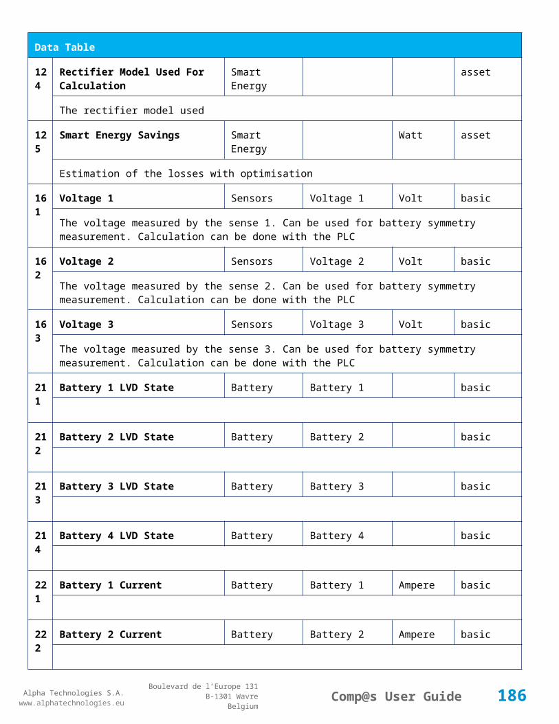
Alpha Technologies S.A.www.alphatechnologies.eu
Alpha Technologies S.A.www.alphatechnologies.eu
Comp@s User GuideBoulevard de l’Europe 131
B-1301 WavreBelgium
Control Table
521
Reset Default Names And Groups Generic Renaming basic
This control element resets all the element Names, Groups and Subgroups to default values for this equipment
522
Reset Default Names And Groups Recursive Generic Renaming basic
This control element resets all the element Names, Groups and Subgroups to default values for this equipment and all sub equipments
7.2.4 MCU1X6M3
Device Information
Name MCU1X6M3
Short Description MCU for rack 3x1800W
Long Description
Hardware Reference 9413 061 85051
Software Reference SOFT 000082 XX
Equipment Type Monitoring Control Unit
ETSI Level /site/energy_system/dc_system
Description Table
Id Name Group SubGroup License
1 Description Description Custom Description basic
A free text zone to write a system description
2 Reference Description Custom Description basic
A free text zone to write the customer reference of the system
11 Product Name Description Product Info basic
The product name of the DC system monitoring
12 Hardware Reference Description Product Info basic
The hardware reference of the DC system monitoring
14 Software Reference Description Product Info asset
The serial number of the DC system monitoring
186

Alpha Technologies S.A.www.alphatechnologies.eu
Alpha Technologies S.A.www.alphatechnologies.eu
Comp@s User GuideBoulevard de l’Europe 131
B-1301 WavreBelgium
Description Table
16 Serial Number Description Product Info asset
The serial number of the DC system monitoring
18 Manufacturing Date Description Product Info asset
The production date of the DC system monitoring
Alarm Table
Id Name Group SubGroup Severity Type (Level)
Set/Clear Delay
1 DC Bus Extra Low DC Bus major (6) 5 / 2
The bus voltage is extra low. The alarm is set when the bus voltage is lower than the configuration parameter 'DC Bus Voltage Extra Low'. There is an hysteresis on the alarm : 'DC Bus Voltage Extra Low Hysteresis'. The alarm is not activated when DC mode is BATTERY TEST
2 DC Bus Low DC Bus minor (4) 5 / 2
The bus voltage is low. The alarm is set when the bus voltage is lower than the configuration parameter 'DC Bus Voltage Low'. There is an hysteresis on the alarm : 'DC Bus Voltage Low Hysteresis'
3 DC Bus High DC Bus minor (4) 5 / 2
The bus voltage is high. The alarm is set when the bus voltage is higher than the configuration paramenter 'DC Bus Voltage High'. There is an hysterisis on the alarm : 'DC Bus Voltage High Hysteresis'
4 DC Bus Extra High DC Bus major (6) 5 / 2
The bus voltage is extra high. The alarm is set when the bus voltage is higher than the configuration paramenter 'DC Bus Voltage Extra High'. There is an hysterisis on the alarm : 'DC Bus Voltage Extra High Hysteresis'
5 DC Bus Voltage Sense Failure
DC Bus major (6) 5 / 2
The DC bus voltage sense is defective. The DC bus voltage is unconnected or unconfigured.
6 Mains Failure AC Bus minor (4) 5 / 2
The number of active rectifiers is equal to 0 and the number of rectifiers in AC failure is greater than 0.
7 Mains Partial Failure AC Bus minor (4) 10 / 2
The number of active rectifiers is greater than 0 and the number of rectifiers in AC failure is greater than 0. Some rectifiers are in AC Failure. It may be caused by an open breaker, a real phase failure, or by a rectifier failure.
187

Alpha Technologies S.A.www.alphatechnologies.eu
Alpha Technologies S.A.www.alphatechnologies.eu
Comp@s User GuideBoulevard de l’Europe 131
B-1301 WavreBelgium
Alarm Table
8 Mains Low AC Bus warning (2) 10 / 2
The main voltage is low on one or more phases. No rectifier is in AC failure. If MCU master type is 30110, 3096 or 3048M6, an hysteresis _phase123Hysteresis is added to the voltage lower limit
10
One Rectifier Failure Rectifiers minor (4) 5 / 2
One rectifier must be replaced or is not powered correctly. The DC fail alarm of the rectifier is set. The number of rectifier with DC Failure is higher than 0, there is no mains failure, and the 'More Than One Rectifier Failure alarm is not set.'
11
More Than One Rectifier Failure
Rectifiers major (6) 10 / 2
There is no mains failure and number of rectifier failures is greater than 1.
12
Missing Rectifiers Rectifiers major (6) 5 / 2
There is not enough rectifier according to the configuration parameter : 'Minimal Number Of Rectifier'
13
Battery Last Test Failed Battery Battery Test minor (3) 5 / 2
The last battery test did not succeed and was not cancelled. Maybe the battery should be replaced.
14
Battery On Discharge Battery minor (4) 10 / 2
The battery is discharging. This means that the load is too high for the installed rectifiers. This alarm is inactive when the system in AC Failure or during a battery test. There is an hysteresis corresponding to battery parameter 'Is discharging current hysteresis'.
17
Battery LVD Relay Open LVD major (6) 5 / 2
The battery Low Voltage Disconnector is open. On Systems without LVD_Status signal, like MCU 1848 or MCU 1x6, the alarm is present only if the signal LVD_COM asks to open the LVD
18
Battery Temperature Too High
Battery Temperature minor (3) 5 / 2
The temperature of the battery is too high and is greater than -600 units. There is an hysteresis corresponding to battery parameter 'Temperature hysteresis'.
19
Battery Temperature Too Low
Battery Temperature minor (3) 5 / 2
The temperature of the battery is too low and is greater than -600 units. There is an hysteresis corresponding to battery parameter 'Temperature hysteresis'.
20
Battery Temperature Sensor Fail
Battery Temperature minor (3) 5 / 2
The battery temperature sensor (NTC) value is inferior to -500 units meaning that it is not connected or defective.
2 Distribution Breaker Open Digital Inputs major (6) 5 / 2
188
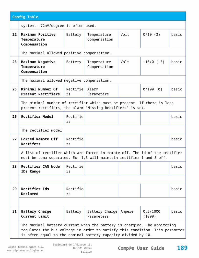
Alpha Technologies S.A.www.alphatechnologies.eu
Alpha Technologies S.A.www.alphatechnologies.eu
Comp@s User GuideBoulevard de l’Europe 131
B-1301 WavreBelgium
Alarm Table
5 This alarm is related to digital input 1. This alarm is activated if digital input value is different to configuration parameter 'Digital Input Alarm Value'
26
Battery Breaker Open Digital Inputs minor (4) 5 / 2
This alarm is related to digital input 2. This alarm is activated if digital input value is different to configuration parameter 'Digital Input Alarm Value'
27
Digital Input 3 Digital Inputs none (0) 5 / 2
This alarm is related to digital input 3. This alarm is activated if digital input value is different to configuration parameter 'Digital Input Alarm Value'
28
Digital Input 4 Digital Inputs none (0) 5 / 2
This alarm is related to digital input 4. This alarm is activated if digital input value is different to configuration parameter 'Digital Input Alarm Value'
Data Table
Id Name Group SubGroup Unit License
1 DC Mode System basic
The DC system can have 4 values: 'FLOAT', 'BOOST', 'BATTERY_TEST', 'AC_FAILURE' or SAFE
2 Previous DC Mode System basic
The previous value of the DC Mode
11 Bus Voltage DC Bus Volt basic
The DC bus voltage in volt.
12 Ratio Delivered On Available Power
System % basic
This is the ratio of the delivered power divided by the installed power, in %.
13 Minutes Since Last AC Failure Begin
AC Bus minute basic
The number of minute since the last AC Failure begin
14 Minutes Since Last AC Failure End
AC Bus minute basic
The number of minute since the last AC Failure end
21 Rectifiers Output Power Rectifiers Watt basic
The sum of the delivered rectifier power
189

Alpha Technologies S.A.www.alphatechnologies.eu
Alpha Technologies S.A.www.alphatechnologies.eu
Comp@s User GuideBoulevard de l’Europe 131
B-1301 WavreBelgium
Data Table
22 Rectifiers Output Current Rectifiers Ampere basic
The sum of the delivered rectifier current
23 Rectifiers Output Power Max Rectifiers Watt basic
The sum of the deliverable rectifier power
24 Rectifiers Output Current Max Rectifiers Ampere basic
The sum of the deliverable rectifier current
31 Number Of Rectifier Max Rectifiers Numbers basic
The maximum possible number of rectifier in this dc system
32 Number Of Present Rectifier Rectifiers Numbers basic
The actual number of present rectifier in this dc system
33 Number Of Absent Rectifier Rectifiers Numbers basic
The actual number of absent rectifier in this dc system
34 Number Of Active Rectifier Rectifiers Numbers basic
The actual number of active rectifier in this dc system. An active rectifier is a rectifier which is present, DC OK, AC OK and not in remote off.
35 Number Of AC-Fail Rectifier Rectifiers Numbers basic
The actual number or rectifier in AC Failure.
36 Number Of DC-Fail Rectifier Rectifiers Numbers basic
The actual number or rectifier with DC Failure.
37 Number Of Remote Off Rectifier Rectifiers Numbers basic
The actual number or rectifier in remote off.
38 Number Of Over Temperature Rectifier
Rectifiers Numbers basic
The actual number or rectifier in OVer Temperature.
51 Load Power Load Watt basic
Estimation of the load power consumption
52 Load Current Load Ampere basic
Estimation of the load current consumption
190

Alpha Technologies S.A.www.alphatechnologies.eu
Alpha Technologies S.A.www.alphatechnologies.eu
Comp@s User GuideBoulevard de l’Europe 131
B-1301 WavreBelgium
Data Table
61 Battery Input Current Battery Ampere basic
Measurement of the battery input current. A negative value means that the battery is discharging
62 Battery Input Power Battery Watt basic
Measurement of the battery input power. A negative value means that the battery is discharging
71 Battery Temperature Battery Temperature degree C basic
The battery temperature
72 Battery Test State Battery Battery Test basic
This is about the result of the last battery test. 9 values are possible : NEVER_TESTED, SUCCESS, ON_GOING, FAILED_TIMEOUT, FAILED_VBUS_TOO_LOW, FAILED_LOAD_TOO_LOW, FAILED_AC_FAILURE, FAILED_CANCELED, FAILED_LVD_OPENED
73 Battery Test Discharged Capacity Ratio
Battery Battery Test % basic
This is the battery capacity, in percent, discharged during the last battery test. This value is updated at the end of the battery test.
74 Battery Test Discharged Capacity Battery Battery Test Ah basic
This is the battery capacity, in ampere hour, discharged during the last battery test. This value is updated at the end of the battery test.
75 Battery Test Final Voltage Battery Battery Test % basic
This is the bus voltage at the end of the last battery test. This value is updated at the end of the battery test.
81 Previous Battery Test State Battery Battery Test basic
The result of the previous battery test
82 Minutes Since Last Test Battery Battery Battery Test basic
The number of minute without battery test
84 Next Scheduled Battery Test Battery Battery Test basic
The date and time of the next time the scheduled battery test will run
91 Battery Charge Capacity Battery % basic
The battery charge capacity, calculated by integration of the current.
92 Calculated Autonomy Battery minute basic
Calculation of the remaining autonomy
191

Alpha Technologies S.A.www.alphatechnologies.eu
Alpha Technologies S.A.www.alphatechnologies.eu
Comp@s User GuideBoulevard de l’Europe 131
B-1301 WavreBelgium
Data Table
93 Battery Current Integration Battery As basic
Actual value of the integration of the current, in Ampere * second
94 Battery Current Integration Battery Ah basic
Actual value of the integration of the current, in Ampere * hour
101
LVD State LVD basic
Actual state of the LVD
111
Relay 1 State Relays Relay 1 basic
Actual state of the Relay 1
112
Relay 2 State Relays Relay 2 basic
Actual state of the Relay 2
113
Relay 3 State Relays Relay 3 basic
Actual state of the Relay 3
114
Relay 4 State Relays Relay 4 basic
Actual state of the Relay 3
121
Efficiency Optimized Number Of Rectifier
Smart Energy asset
The optimal number of ON rectifier for Efficiency Optimization
122
System Loss Without Optimisation
Smart Energy Watt underdev
Estimation of the losses without optimisation
123
System Loss With Optimisation Smart Energy Watt underdev
Estimation of the losses with optimisation
124
Rectifier Model Used For Calculation
Smart Energy asset
The rectifier model used
125
Smart Energy Savings Smart Energy Watt asset
Estimation of the losses with optimisation
192

Alpha Technologies S.A.www.alphatechnologies.eu
Alpha Technologies S.A.www.alphatechnologies.eu
Comp@s User GuideBoulevard de l’Europe 131
B-1301 WavreBelgium
Config Table
Id Name Group SubGroup Unit Range: Min/Max (default)
License
193

Alpha Technologies S.A.www.alphatechnologies.eu
Alpha Technologies S.A.www.alphatechnologies.eu
Comp@s User GuideBoulevard de l’Europe 131
B-1301 WavreBelgium
Config Table
1 DC Bus Float Voltage at 25 degC
DC Bus Volt 40/60 (54) basic
The floating dc bus voltage of the system at 25 Celsius degree
2 DC Bus Voltage Extra Low
DC Bus Alarm Parameters Volt 40/60 (45) basic
The bus voltage under which the alarm 'DC Bus Voltage Extra Low' is set.
3 DC Bus Voltage Extra Low Hysteresis
DC Bus Alarm Parameters Volt 0/5 (1) basic
The voltage hysteresis on the alarm 'DC Bus Voltage Extra Low'.
4 DC Bus Voltage Low DC Bus Alarm Parameters Volt 40/60 (48) basic
The bus voltage under which the alarm 'DC Bus Voltage Low' is set.
5 DC Bus Voltage Low Hysteresis
DC Bus Alarm Parameters Volt 0/5 (0.5) basic
The voltage hysteresis on the alarm 'DC Bus Voltage Low
6 DC Bus Voltage High DC Bus Alarm Parameters Volt 40/60 (56.5) basic
The bus voltage over which the alarm 'DC Bus Voltage High' is set.
7 DC Bus Voltage High Hysteresis
DC Bus Alarm Parameters Volt 0/5 (0.5) basic
The voltage hysteresis on the alarm 'DC Bus Voltage High
8 DC Bus Voltage Extra High
DC Bus Alarm Parameters Volt 40/60 (58) basic
The bus voltage over which the alarm 'DC Bus Voltage Extra High' is set.
9 DC Bus Voltage Extra High Hysteresis
DC Bus Alarm Parameters Volt 0/5 (0.5) basic
The voltage hysteresis on the alarm 'DC Bus Voltage Extra High
10 LVD Disconnect Voltage LVD Volt 0/50 (43.2) basic
The dc bus voltage under which the battery must be disconnected of the bus. This allows preserving the battery life. The load will be unpowered.
11 LVD Disconnect Delay LVD second 1/2000 (1) basic
The delay in second before disconnecting the battery if the dc bus voltage is under the configured disconnected voltage. This avoids disconnection during a low bus transient.
21 Temperature Battery Temperature mV/degree -1000/0 (-72) basic
194

Alpha Technologies S.A.www.alphatechnologies.eu
Alpha Technologies S.A.www.alphatechnologies.eu
Comp@s User GuideBoulevard de l’Europe 131
B-1301 WavreBelgium
Config Table
Compensation Slope Compensation
The slope of the battery temperature compensation in mv/degree. For a 48V system, -72mV/degree is often used.
22 Maximum Positive Temperature Compensation
Battery Temperature Compensation
Volt 0/10 (3) basic
The maximal allowed positive compensation.
23 Maximum Negative Temperature Compensation
Battery Temperature Compensation
Volt -10/0 (-3) basic
The maximal allowed negative compensation.
25 Minimal Number Of Present Rectifiers
Rectifiers Alarm Parameters 0/100 (0) basic
The minimal number of rectifier which must be present. If there is less present rectifiers, the alarm 'Missing Rectifiers' is set.
26 Rectifier Model Rectifiers basic
The rectifier model
27 Forced Remote Off Rectifers
Rectifiers basic
A list of rectifier which are forced in remote off. The id of the rectifier must be coma separated. Ex: 1,3 will maintain rectifier 1 and 3 off.
31 Battery Charge Current Limit
Battery Battery Charge Parameters
Ampere 0.5/1000 (1000) basic
The maximal battery current when the battery is charging. The monitoring regulates the bus voltage in order to satisfy this condition. This parameter is often equal to the nominal battery capacity divided by 10.
32 Battery String Capacity Battery Ah 3/1000 (100) basic
The battery capacity in Ah.
33 Battery Temperature Low
Battery Alarm Parameters degree C -100/20 (0) basic
The temperature under which the alarm 'Battery Temperature Too Low' must be set.
34 Battery Temperature High
Battery Alarm Parameters degree C 5/100 (40) basic
The temperature over which the alarm 'Battery Temperature Too High' must be set.
195

Alpha Technologies S.A.www.alphatechnologies.eu
Alpha Technologies S.A.www.alphatechnologies.eu
Comp@s User GuideBoulevard de l’Europe 131
B-1301 WavreBelgium
Config Table
35 Battery Temperature Hysteresis
Battery Alarm Parameters degree C 0/10 (2) basic
The hysteresis on the 'Battery Temperature Too High' and 'Battery Temperature Too Low' alarms.
36 Minimal Current For Discharging Alarm
Battery Alarm Parameters Ampere 0/1000 (3) basic
The minimal discharging current to set the 'Battery On Discharge' alarm.
37 Current Hysteresis For Discharging Alarm
Battery Alarm Parameters Ampere 0/50 (1) basic
The hysteresis on the 'Battery On Discharge' alarm.
51 Boost Automatic Battery Boost False/False (False)
battery
The boost mode must be automatically after the fact that during a mains failure, the bus voltage went under the configured 'Boost Activation Low Voltage'. This allows charging the battery faster.
52 Boost Activation Low Voltage
Battery Boost Volt 43/50 (46) battery
The voltage under which the boost mode can be activated.
53 Boost Termination Voltage
Battery Boost Volt 50/58 (56.4) battery
The voltage over which the system must go back to floating mode.
54 Boost Termination Current
Battery Boost Ampere 0/100 (4) battery
The battery charging current under which the system must go back to floating mode.
55 Boost Termination Time Battery Boost minute 10/240 (120) battery
The time in minute after which the system must go back in floating mode.
70 Battery Test End Voltage
Battery Battery Test Volt 30/60 (46) battery
The voltage at which any battery test must be stopped.
71 Battery Test Discharge Ratio
Battery Battery Test % 0/100 (0) battery
The ratio of the battery capacity to discharge. If 30 is set, 30% of the battery will be discharged during the test
72 Battery Test Interval Battery Battery Test day 0/3000 (0) battery
The number of days between two automatically started battery test. If this parameter is set to 0, the
196
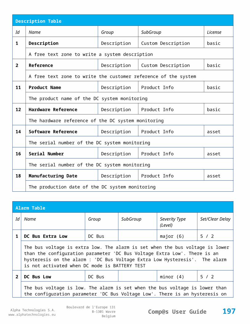
Alpha Technologies S.A.www.alphatechnologies.eu
Alpha Technologies S.A.www.alphatechnologies.eu
Comp@s User GuideBoulevard de l’Europe 131
B-1301 WavreBelgium
Config Table
battery test is not started automatically. The user can remotely or locally start or force this test.
73 Battery Test Discharge Current
Battery Battery Test Ampere 3/100 (1000) battery
The current at which the battery must be discharged during a battery test. The monitoring regulates the bus voltage in order to satisfy this condition. The load current must be of course higher than this parameter.
74 Battery Test Minimal Discharge Current
Battery Battery Test Ampere 2/90 (2) battery
The battery current under which the battery test must be stopped because the load is too low.
75 Battery Test Time Out Battery Battery Test minute 1/5000 (10) battery
The timeout in minute after which the battery test must be stopped.
76 Battery Test Requested Minutes Without Mains Failure
Battery Battery Test minute 0/5000 (1440) battery
The minimal time in minute without mains failure in order to allow a battery start. This parameter is not taken into account when the battery test is forced.
77 Battery Test Scheduler Cron Rule
Battery Battery Test basic
83 Smart Energy Boolean Condition
Smart Energy
asset
This is the boolean condition which allows or not to automatically optimize the number of rectifier in remote off.
86 Battery LVD Node Id LVD True/False (False)
basic
This is a list of the node id of the Smart Electronic LVDs, coma separated
91 Digital Input 1 Name Digital Inputs
Digital Input 1 Distribution Breaker Open
basic
The name of the digital input 1
92 Digital Input 1 Normally Closed
Digital Inputs
Digital Input 1 True/False (True)
basic
True/False value defining if the digital input 1 is normally closed. If this digital input is not in this default state, the related alarm is set.
93 Digital Input 2 Name Digital Inputs
Digital Input 2 Battery Breaker Open
basic
197

Alpha Technologies S.A.www.alphatechnologies.eu
Alpha Technologies S.A.www.alphatechnologies.eu
Comp@s User GuideBoulevard de l’Europe 131
B-1301 WavreBelgium
Config Table
The name of the digital input 2
94 Digital Input 2 Normally Closed
Digital Inputs
Digital Input 2 True/False (True)
basic
True/False value defining if the digital input 2 is normally closed. If this digital input is not in this default state, the related alarm is set.
95 Digital Input 3 Name Digital Inputs
Digital Input 3 Digital Input 3 basic
The name of the digital input 3
96 Digital Input 3 Normally Closed
Digital Inputs
Digital Input 3 True/False (True)
basic
True/False value defining if the digital input 3 is normally closed. If this digital input is not in this default state, the related alarm is set.
97 Digital Input 4 Name Digital Inputs
Digital Input 4 Digital Input 4 basic
The name of the digital input 4
98 Digital Input 4 Normally Closed
Digital Inputs
Digital Input 4 True/False (True)
basic
True/False value defining if the digital input 4 is normally closed. If this digital input is not in this default state, the related alarm is set.
111
Dry Alarm 1 Alternative Boolean Condition
Relays Relay 1 plc
Another Boolean condition to activate the dry alarm relay 1. The way to define boolean condition is detailed in the PLC chapter.
112
Dry Alarm 2 Alternative Boolean Condition
Relays Relay 2 plc
Another Boolean condition to activate the dry alarm relay 2. The way to define boolean condition is detailed in the PLC chapter.
113
Dry Alarm 3 Alternative Boolean Condition
Relays Relay 3 plc
Another Boolean condition to activate the dry alarm relay 3. The way to define boolean condition is detailed in the PLC chapter.
114
Dry Alarm 4 Alternative Boolean Condition
Relays Relay 4 plc
Another Boolean condition to activate the dry alarm relay 4. The way to define boolean condition is detailed in the PLC chapter.
198

Alpha Technologies S.A.www.alphatechnologies.eu
Alpha Technologies S.A.www.alphatechnologies.eu
Comp@s User GuideBoulevard de l’Europe 131
B-1301 WavreBelgium
Config Table
521
Read Access User Numbers
Generic Allowed Users (1,2,3,4,5) basic
The list of the user numbers which have read access to this equipment. The user numbers are coma separated. The accepted user id are 1,2,3,4 and 5. Ex: 1,3,4
522
Write Access User Numbers
Generic Allowed Users () basic
The list of the user numbers which have write access to this equipment. This means that these users can modify the configuration element, the alarm settings and use the control elements. The user numbers are coma separated. The accepted user ids are 1,2,3,4 and 5. Ex: 1,3,4
601
Event Table Length Generic Events 10/4000 (100) basic
The maximum length of the table. The value must be comprised between 10 and 4000
602
Event Table Length By Rectifier
Generic Events 10/4000 (100) basic
The maximum length of the table. The value must be comprised between 10 and 4000
901
Number Of PLC Data PLC (0) plc
The number of PLC data. Every equipment can manage up to 20 user programmable data. Data elements are automatically added in the data table. Configuration parameters are added to set the PLC Data Name and the PLC Data Mathematical calculation. In order to use these functionalities, you need a license with the 'PLC' module
902
Number Of PLC Alarm PLC (0) plc
The number of PLC alarm. Every equipment can manage up to 20 user programmable alarms. Alarm elements are automatically added in the alarm table. The alarm parameters are added to set the PLC Alarm Name and the PLC Alarm Boolean condition. In order to use these functionalities, you need a licence with the 'PLC' module
Control Table
Id Name Group SubGroup License
1 Back To Float System basic
The dc system must go back in floating mode.
2 Start Battery Test System battery
The dc system must start a battery test.
3 Force Battery Test System battery
The dc system must force a battery test.
199
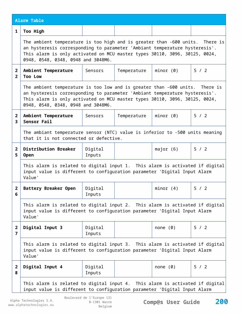
Alpha Technologies S.A.www.alphatechnologies.eu
Alpha Technologies S.A.www.alphatechnologies.eu
Comp@s User GuideBoulevard de l’Europe 131
B-1301 WavreBelgium
Control Table
4 Start Boost Mode System battery
The dc system must go in boost mode.
11 Open The LVD LVD basic
Try to open the LVD. It could not work if the LVD is electronic, and the request will be canceled after 15 sec.
12 Close The LVD LVD basic
The LVD must be closed
21 Correct Battery Current Offset Battery basic
31 Reset Battery Current Integration Battery basic
Reset the integration of the battery current.
41 Reset Last Battery Test State Battery battery
Reset the state of the last battery test. If an alarm 'Battery Last Test Failed' is set, the alarm will be cleared.
51 Save Configuration In MCU Save basic
Save configuration parameters in the MCU microcontroller. If comp@s is not present, the system will be correctly managed.
55 Set MCU Specific Configuration Id Advanced Factory basic
This control allows to reconfigure the MCU to support specific hardware configuration, with embedded distribution for example
61 Set Digital Input 4 Counter Value Digital Inputs Digital Input 4 basic
Set Counter Value
111
Invert Relay 1 State For X Seconds Relays Relay 1 basic
Generate Pulse on relay 1
112
Invert Relay 2 State For X Seconds Relays Relay 2 basic
Generate Pulse on relay 2
113
Invert Relay 3 State For X Seconds Relays Relay 3 basic
Generate Pulse on relay 3
11 Invert Relay 4 State For X Seconds Relays Relay 4 basic
200

Alpha Technologies S.A.www.alphatechnologies.eu
Alpha Technologies S.A.www.alphatechnologies.eu
Comp@s User GuideBoulevard de l’Europe 131
B-1301 WavreBelgium
Control Table
4 Generate Pulse on relay 4
501
Clear My Events Generic Events basic
By writing '1' to this control element, all the events of this equipment will be cleared.
502
Clear All Events Generic Events basic
By writing '1' to this control element, all the events of this equipment and all the events of all the sub-equipments will be cleared.
511
Add Event Generic Events basic
This control element adds an event of severity none. The event name is the text written to this control element
512
Add Major Event Generic Events basic
This control element adds an event of severity major. The event name is the text written to this control element
521
Reset Default Names And Groups Generic Renaming basic
This control element resets all the element Names, Groups and Subgroups to default values for this equipment
522
Reset Default Names And Groups Recursive Generic Renaming basic
This control element resets all the element Names, Groups and Subgroups to default values for this equipment and all sub equipments
7.2.5 MCU0024
Device Information
Name MCU0024
Short Description MCU for rack 6x1500W +24V
Long Description
Hardware Reference 9413 000 XXXX
Software Reference SOFT 000042 XX
Equipment Type Monitoring Control Unit
ETSI Level /site/energy_system/dc_system
201
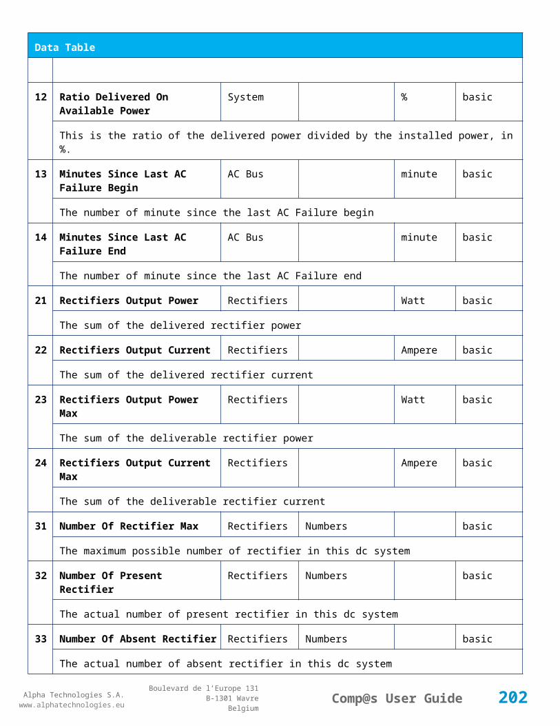
Alpha Technologies S.A.www.alphatechnologies.eu
Alpha Technologies S.A.www.alphatechnologies.eu
Comp@s User GuideBoulevard de l’Europe 131
B-1301 WavreBelgium
Description Table
Id Name Group SubGroup License
1 Description Description Custom Description basic
A free text zone to write a system description
2 Reference Description Custom Description basic
A free text zone to write the customer reference of the system
11 Product Name Description Product Info basic
The product name of the DC system monitoring
12 Hardware Reference Description Product Info basic
The hardware reference of the DC system monitoring
14 Software Reference Description Product Info asset
The serial number of the DC system monitoring
16 Serial Number Description Product Info asset
The serial number of the DC system monitoring
18 Manufacturing Date Description Product Info asset
The production date of the DC system monitoring
Alarm Table
Id Name Group SubGroup Severity Type (Level)
Set/Clear Delay
1 DC Bus Extra Low DC Bus major (6) 5 / 2
The bus voltage is extra low. The alarm is set when the bus voltage is lower than the configuration parameter 'DC Bus Voltage Extra Low'. There is an hysteresis on the alarm : 'DC Bus Voltage Extra Low Hysteresis'. The alarm is not activated when DC mode is BATTERY TEST
2 DC Bus Low DC Bus minor (4) 5 / 2
The bus voltage is low. The alarm is set when the bus voltage is lower than the configuration parameter 'DC Bus Voltage Low'. There is an hysteresis on the alarm : 'DC Bus Voltage Low Hysteresis'
3 DC Bus High DC Bus minor (4) 5 / 2
The bus voltage is high. The alarm is set when the bus voltage is higher than the configuration paramenter 'DC Bus Voltage High'. There is an hysterisis on the alarm : 'DC Bus Voltage High Hysteresis'
202

Alpha Technologies S.A.www.alphatechnologies.eu
Alpha Technologies S.A.www.alphatechnologies.eu
Comp@s User GuideBoulevard de l’Europe 131
B-1301 WavreBelgium
Alarm Table
4 DC Bus Extra High DC Bus major (6) 5 / 2
The bus voltage is extra high. The alarm is set when the bus voltage is higher than the configuration paramenter 'DC Bus Voltage Extra High'. There is an hysterisis on the alarm : 'DC Bus Voltage Extra High Hysteresis'
5 DC Bus Voltage Sense Failure
DC Bus major (6) 5 / 2
The DC bus voltage sense is defective. The DC bus voltage is unconnected or unconfigured.
6 Mains Failure AC Bus minor (4) 5 / 2
The number of active rectifiers is equal to 0 and the number of rectifiers in AC failure is greater than 0.
7 Mains Partial Failure AC Bus minor (4) 10 / 2
The number of active rectifiers is greater than 0 and the number of rectifiers in AC failure is greater than 0. Some rectifiers are in AC Failure. It may be caused by an open breaker, a real phase failure, or by a rectifier failure.
8 Mains Low AC Bus warning (2) 10 / 2
The main voltage is low on one or more phases. No rectifier is in AC failure. If MCU master type is 30110, 3096 or 3048M6, an hysteresis _phase123Hysteresis is added to the voltage lower limit
10
One Rectifier Failure Rectifiers minor (4) 5 / 2
One rectifier must be replaced or is not powered correctly. The DC fail alarm of the rectifier is set. The number of rectifier with DC Failure is higher than 0, there is no mains failure, and the 'More Than One Rectifier Failure alarm is not set.'
11
More Than One Rectifier Failure
Rectifiers major (6) 10 / 2
There is no mains failure and number of rectifier failures is greater than 1.
12
Missing Rectifiers Rectifiers major (6) 5 / 2
There is not enough rectifier according to the configuration parameter : 'Minimal Number Of Rectifier'
13
Battery Last Test Failed Battery Battery Test minor (3) 5 / 2
The last battery test did not succeed and was not cancelled. Maybe the battery should be replaced.
14
Battery On Discharge Battery minor (4) 10 / 2
The battery is discharging. This means that the load is too high for the installed rectifiers. This alarm is inactive when the system in AC Failure or during a battery test. There is an hysteresis corresponding to battery parameter 'Is discharging current hysteresis'.
17
Battery LVD Relay Open LVD major (6) 5 / 2
The battery Low Voltage Disconnector is open. On Systems without LVD_Status signal, like MCU 1848
203
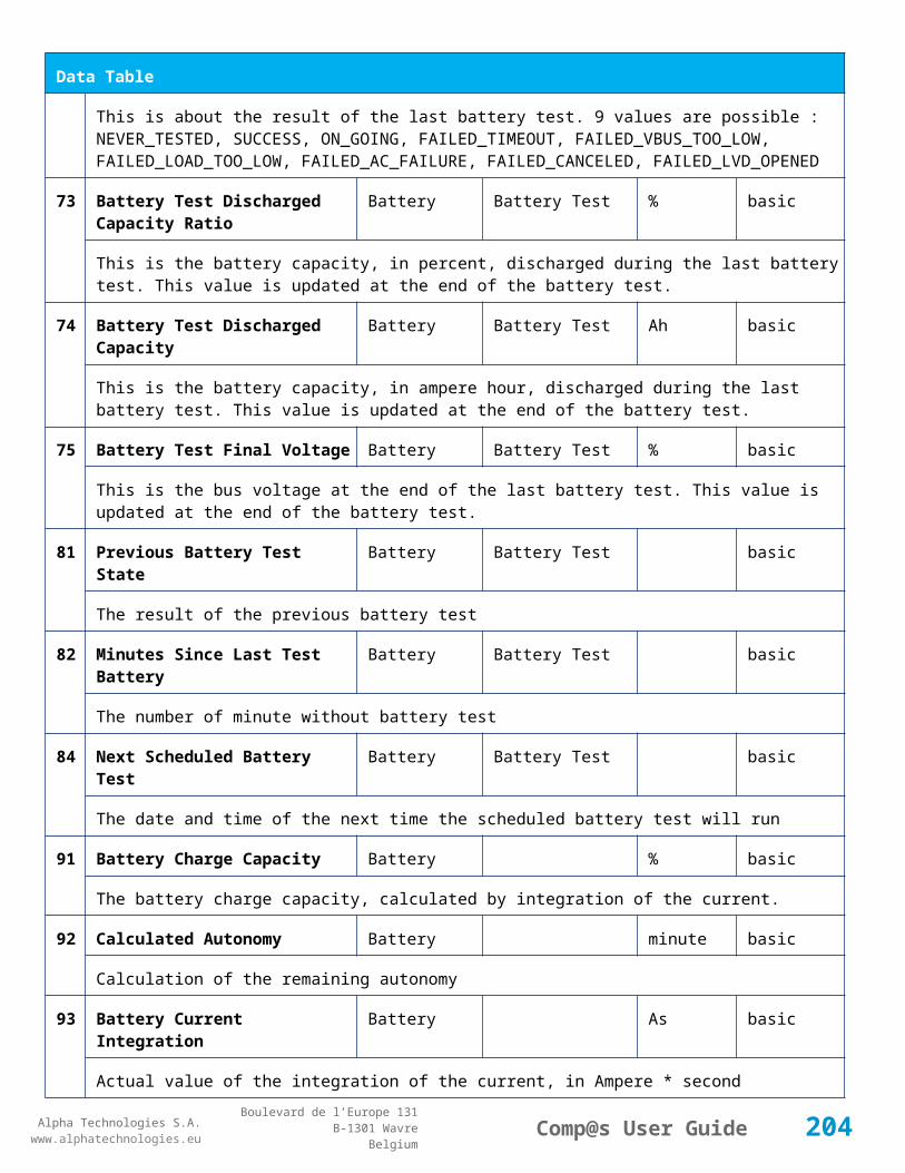
Alpha Technologies S.A.www.alphatechnologies.eu
Alpha Technologies S.A.www.alphatechnologies.eu
Comp@s User GuideBoulevard de l’Europe 131
B-1301 WavreBelgium
Alarm Table
or MCU 1x6, the alarm is present only if the signal LVD_COM asks to open the LVD
18
Battery Temperature Too High
Battery Temperature minor (3) 5 / 2
The temperature of the battery is too high and is greater than -600 units. There is an hysteresis corresponding to battery parameter 'Temperature hysteresis'.
19
Battery Temperature Too Low
Battery Temperature minor (3) 5 / 2
The temperature of the battery is too low and is greater than -600 units. There is an hysteresis corresponding to battery parameter 'Temperature hysteresis'.
20
Battery Temperature Sensor Fail
Battery Temperature minor (3) 5 / 2
The battery temperature sensor (NTC) value is inferior to -500 units meaning that it is not connected or defective.
21
Ambient Temperature Too High
Sensors Temperature minor (0) 5 / 2
The ambient temperature is too high and is greater than -600 units. There is an hysteresis corresponding to parameter 'Ambiant temperature hysteresis'. This alarm is only activated on MCU master types 30110, 3096, 30125, 0024, 0948, 0548, 0348, 0948 and 3048M6.
22
Ambient Temperature Too Low
Sensors Temperature minor (0) 5 / 2
The ambient temperature is too low and is greater than -600 units. There is an hysteresis corresponding to parameter 'Ambiant temperature hysteresis'. This alarm is only activated on MCU master types 30110, 3096, 30125, 0024, 0948, 0548, 0348, 0948 and 3048M6.
23
Ambient Temperature Sensor Fail
Sensors Temperature minor (0) 5 / 2
The ambiant temperature sensor (NTC) value is inferior to -500 units meaning that it is not connected or defective.
25
Distribution Breaker Open Digital Inputs major (6) 5 / 2
This alarm is related to digital input 1. This alarm is activated if digital input value is different to configuration parameter 'Digital Input Alarm Value'
26
Battery Breaker Open Digital Inputs minor (4) 5 / 2
This alarm is related to digital input 2. This alarm is activated if digital input value is different to configuration parameter 'Digital Input Alarm Value'
27
Digital Input 3 Digital Inputs none (0) 5 / 2
This alarm is related to digital input 3. This alarm is activated if digital input value is different to configuration parameter 'Digital Input Alarm Value'
204

Alpha Technologies S.A.www.alphatechnologies.eu
Alpha Technologies S.A.www.alphatechnologies.eu
Comp@s User GuideBoulevard de l’Europe 131
B-1301 WavreBelgium
Alarm Table
28
Digital Input 4 Digital Inputs none (0) 5 / 2
This alarm is related to digital input 4. This alarm is activated if digital input value is different to configuration parameter 'Digital Input Alarm Value'
29
Digital Input 5 Digital Inputs none (0) 5 / 2
This alarm is related to digital input 5. This alarm is activated if digital input value is different to configuration parameter 'Digital Input Alarm Value'
30
Digital Input 6 Digital Inputs none (0) 5 / 2
This alarm is related to digital input 6. This alarm is activated if digital input value is different to configuration parameter 'Digital Input Alarm Value'
31
Digital Input 7 Digital Inputs none (0) 5 / 2
This alarm is related to digital input 7. This alarm is activated if digital input value is different to configuration parameter 'Digital Input Alarm Value'
32
Digital Input 8 Digital Inputs none (0) 5 / 2
This alarm is related to digital input 8. This alarm is activated if digital input value is different to configuration parameter 'Digital Input Alarm Value'
Data Table
Id Name Group SubGroup Unit License
1 DC Mode System basic
The DC system can have 4 values: 'FLOAT', 'BOOST', 'BATTERY_TEST', 'AC_FAILURE' or SAFE
2 Previous DC Mode System basic
The previous value of the DC Mode
11 Bus Voltage DC Bus Volt basic
The DC bus voltage in volt.
12 Ratio Delivered On Available Power
System % basic
This is the ratio of the delivered power divided by the installed power, in %.
13 Minutes Since Last AC Failure Begin
AC Bus minute basic
The number of minute since the last AC Failure begin
14 Minutes Since Last AC Failure AC Bus minute basic
205
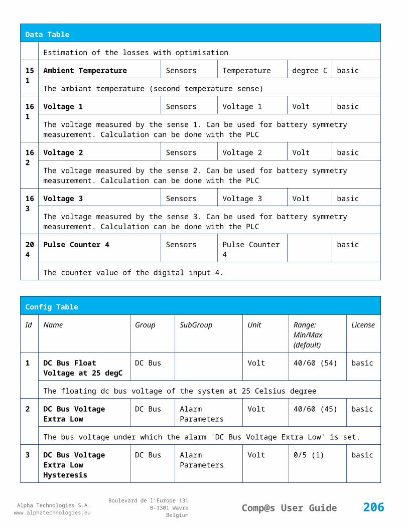
Alpha Technologies S.A.www.alphatechnologies.eu
Alpha Technologies S.A.www.alphatechnologies.eu
Comp@s User GuideBoulevard de l’Europe 131
B-1301 WavreBelgium
Data Table
End
The number of minute since the last AC Failure end
21 Rectifiers Output Power Rectifiers Watt basic
The sum of the delivered rectifier power
22 Rectifiers Output Current Rectifiers Ampere basic
The sum of the delivered rectifier current
23 Rectifiers Output Power Max Rectifiers Watt basic
The sum of the deliverable rectifier power
24 Rectifiers Output Current Max Rectifiers Ampere basic
The sum of the deliverable rectifier current
31 Number Of Rectifier Max Rectifiers Numbers basic
The maximum possible number of rectifier in this dc system
32 Number Of Present Rectifier Rectifiers Numbers basic
The actual number of present rectifier in this dc system
33 Number Of Absent Rectifier Rectifiers Numbers basic
The actual number of absent rectifier in this dc system
34 Number Of Active Rectifier Rectifiers Numbers basic
The actual number of active rectifier in this dc system. An active rectifier is a rectifier which is present, DC OK, AC OK and not in remote off.
35 Number Of AC-Fail Rectifier Rectifiers Numbers basic
The actual number or rectifier in AC Failure.
36 Number Of DC-Fail Rectifier Rectifiers Numbers basic
The actual number or rectifier with DC Failure.
37 Number Of Remote Off Rectifier Rectifiers Numbers basic
The actual number or rectifier in remote off.
38 Number Of Over Temperature Rectifier
Rectifiers Numbers basic
The actual number or rectifier in OVer Temperature.
206

Alpha Technologies S.A.www.alphatechnologies.eu
Alpha Technologies S.A.www.alphatechnologies.eu
Comp@s User GuideBoulevard de l’Europe 131
B-1301 WavreBelgium
Data Table
41 Mains Phase 1 Voltage AC Bus Volt basic
The voltage on AC phase 1
42 Mains Phase 2 Voltage AC Bus Volt basic
The voltage on AC phase 2
43 Mains Phase 3 Voltage AC Bus Volt basic
The voltage on AC phase 3
51 Load Power Load Watt basic
Estimation of the load power consumption
52 Load Current Load Ampere basic
Estimation of the load current consumption
61 Battery Input Current Battery Ampere basic
Measurement of the battery input current. A negative value means that the battery is discharging
62 Battery Input Power Battery Watt basic
Measurement of the battery input power. A negative value means that the battery is discharging
71 Battery Temperature Battery Temperature degree C basic
The battery temperature
72 Battery Test State Battery Battery Test basic
This is about the result of the last battery test. 9 values are possible : NEVER_TESTED, SUCCESS, ON_GOING, FAILED_TIMEOUT, FAILED_VBUS_TOO_LOW, FAILED_LOAD_TOO_LOW, FAILED_AC_FAILURE, FAILED_CANCELED, FAILED_LVD_OPENED
73 Battery Test Discharged Capacity Ratio
Battery Battery Test % basic
This is the battery capacity, in percent, discharged during the last battery test. This value is updated at the end of the battery test.
74 Battery Test Discharged Capacity
Battery Battery Test Ah basic
This is the battery capacity, in ampere hour, discharged during the last battery test. This value is updated at the end of the battery test.
75 Battery Test Final Voltage Battery Battery Test % basic
This is the bus voltage at the end of the last battery test. This value is updated at the end of the battery test.
207

Alpha Technologies S.A.www.alphatechnologies.eu
Alpha Technologies S.A.www.alphatechnologies.eu
Comp@s User GuideBoulevard de l’Europe 131
B-1301 WavreBelgium
Data Table
81 Previous Battery Test State Battery Battery Test basic
The result of the previous battery test
82 Minutes Since Last Test Battery Battery Battery Test basic
The number of minute without battery test
84 Next Scheduled Battery Test Battery Battery Test basic
The date and time of the next time the scheduled battery test will run
91 Battery Charge Capacity Battery % basic
The battery charge capacity, calculated by integration of the current.
92 Calculated Autonomy Battery minute basic
Calculation of the remaining autonomy
93 Battery Current Integration Battery As basic
Actual value of the integration of the current, in Ampere * second
94 Battery Current Integration Battery Ah basic
Actual value of the integration of the current, in Ampere * hour
101
LVD State LVD basic
Actual state of the LVD
111
Relay 1 State Relays Relay 1 basic
Actual state of the Relay 1
112
Relay 2 State Relays Relay 2 basic
Actual state of the Relay 2
113
Relay 3 State Relays Relay 3 basic
Actual state of the Relay 3
114
Relay 4 State Relays Relay 4 basic
Actual state of the Relay 3
121
Efficiency Optimized Number Of Rectifier
Smart Energy asset
The optimal number of ON rectifier for Efficiency Optimization
12 System Loss Without Smart Energy Watt underdev
208

Alpha Technologies S.A.www.alphatechnologies.eu
Alpha Technologies S.A.www.alphatechnologies.eu
Comp@s User GuideBoulevard de l’Europe 131
B-1301 WavreBelgium
Data Table
2 Optimisation
Estimation of the losses without optimisation
123
System Loss With Optimisation Smart Energy Watt underdev
Estimation of the losses with optimisation
124
Rectifier Model Used For Calculation
Smart Energy asset
The rectifier model used
125
Smart Energy Savings Smart Energy Watt asset
Estimation of the losses with optimisation
151
Ambient Temperature Sensors Temperature degree C basic
The ambiant temperature (second temperature sense)
161
Voltage 1 Sensors Voltage 1 Volt basic
The voltage measured by the sense 1. Can be used for battery symmetry measurement. Calculation can be done with the PLC
162
Voltage 2 Sensors Voltage 2 Volt basic
The voltage measured by the sense 2. Can be used for battery symmetry measurement. Calculation can be done with the PLC
163
Voltage 3 Sensors Voltage 3 Volt basic
The voltage measured by the sense 3. Can be used for battery symmetry measurement. Calculation can be done with the PLC
204
Pulse Counter 4 Sensors Pulse Counter 4 basic
The counter value of the digital input 4.
Config Table
Id Name Group SubGroup Unit Range: Min/Max (default)
License
1 DC Bus Float Voltage at 25 degC
DC Bus Volt 20/30 (27) basic
The floating dc bus voltage of the system at 25 Celsius degree
2 DC Bus Voltage Extra DC Bus Alarm Parameters Volt 20/30 (22) basic
209

Alpha Technologies S.A.www.alphatechnologies.eu
Alpha Technologies S.A.www.alphatechnologies.eu
Comp@s User GuideBoulevard de l’Europe 131
B-1301 WavreBelgium
Config Table
Low
The bus voltage under which the alarm 'DC Bus Voltage Extra Low' is set.
3 DC Bus Voltage Extra Low Hysteresis
DC Bus Alarm Parameters Volt 0/2 (0) basic
The voltage hysteresis on the alarm 'DC Bus Voltage Extra Low'.
4 DC Bus Voltage Low DC Bus Alarm Parameters Volt 20/30 (24) basic
The bus voltage under which the alarm 'DC Bus Voltage Low' is set.
5 DC Bus Voltage Low Hysteresis
DC Bus Alarm Parameters Volt 0/2 (0.25) basic
The voltage hysteresis on the alarm 'DC Bus Voltage Low
6 DC Bus Voltage High DC Bus Alarm Parameters Volt 20/30 (28.25) basic
The bus voltage over which the alarm 'DC Bus Voltage High' is set.
7 DC Bus Voltage High Hysteresis
DC Bus Alarm Parameters Volt 0/2 (0.25) basic
The voltage hysteresis on the alarm 'DC Bus Voltage High
8 DC Bus Voltage Extra High
DC Bus Alarm Parameters Volt 20/30 (29) basic
The bus voltage over which the alarm 'DC Bus Voltage Extra High' is set.
9 DC Bus Voltage Extra High Hysteresis
DC Bus Alarm Parameters Volt 0/2 (0.25) basic
The voltage hysteresis on the alarm 'DC Bus Voltage Extra High
10 LVD Disconnect Voltage LVD Volt 0/25 (21.6) basic
The dc bus voltage under which the battery must be disconnected of the bus. This allows preserving the battery life. The load will be unpowered.
11 LVD Disconnect Delay LVD second 1/1000 (1) basic
The delay in second before disconnecting the battery if the dc bus voltage is under the configured disconnected voltage. This avoids disconnection during a low bus transient.
21 Temperature Compensation Slope
Battery Temperature Compensation
mV/degree -500/0 (-36) basic
The slope of the battery temperature compensation in mv/degree. For a 48V system, -72mV/degree is often used.
22 Maximum Positive Battery Temperature Volt 0/5 (1) basic
210

Alpha Technologies S.A.www.alphatechnologies.eu
Alpha Technologies S.A.www.alphatechnologies.eu
Comp@s User GuideBoulevard de l’Europe 131
B-1301 WavreBelgium
Config Table
Temperature Compensation
Compensation
The maximal allowed positive compensation.
23 Maximum Negative Temperature Compensation
Battery Temperature Compensation
Volt -5/0 (-1) basic
The maximal allowed negative compensation.
25 Minimal Number Of Present Rectifiers
Rectifiers Alarm Parameters 0/100 (0) basic
The minimal number of rectifier which must be present. If there is less present rectifiers, the alarm 'Missing Rectifiers' is set.
26 Rectifier Model Rectifiers basic
The rectifier model
27 Forced Remote Off Rectifers
Rectifiers basic
A list of rectifier which are forced in remote off. The id of the rectifier must be coma separated. Ex: 1,3 will maintain rectifier 1 and 3 off.
31 Battery Charge Current Limit
Battery Battery Charge Parameters
Ampere 0.5/1000 (1000) basic
The maximal battery current when the battery is charging. The monitoring regulates the bus voltage in order to satisfy this condition. This parameter is often equal to the nominal battery capacity divided by 10.
32 Battery String Capacity Battery Ah 3/1000 (100) basic
The battery capacity in Ah.
33 Battery Temperature Low
Battery Alarm Parameters degree C -100/20 (0) basic
The temperature under which the alarm 'Battery Temperature Too Low' must be set.
34 Battery Temperature High
Battery Alarm Parameters degree C 5/100 (40) basic
The temperature over which the alarm 'Battery Temperature Too High' must be set.
35 Battery Temperature Hysteresis
Battery Alarm Parameters degree C 0/10 (2) basic
The hysteresis on the 'Battery Temperature Too High' and 'Battery Temperature Too Low' alarms.
36 Minimal Current For Battery Alarm Parameters Ampere 0/1000 (3) basic
211

Alpha Technologies S.A.www.alphatechnologies.eu
Alpha Technologies S.A.www.alphatechnologies.eu
Comp@s User GuideBoulevard de l’Europe 131
B-1301 WavreBelgium
Config Table
Discharging Alarm
The minimal discharging current to set the 'Battery On Discharge' alarm.
37 Current Hysteresis For Discharging Alarm
Battery Alarm Parameters Ampere 0/50 (1) basic
The hysteresis on the 'Battery On Discharge' alarm.
41 Shunt Rating At 60mV Current Sensors
Shunt 1 Ampere 25/5000 (250) basic
The rating of the battery shunt at 60mV.
51 Boost Automatic Battery Boost False/False (False)
battery
The boost mode must be automatically after the fact that during a mains failure, the bus voltage went under the configured 'Boost Activation Low Voltage'. This allows charging the battery faster.
52 Boost Activation Low Voltage
Battery Boost Volt 21/25 (23) battery
The voltage under which the boost mode can be activated.
53 Boost Termination Voltage
Battery Boost Volt 25/29 (28.2) battery
The voltage over which the system must go back to floating mode.
54 Boost Termination Current
Battery Boost Ampere 0/100 (4) battery
The battery charging current under which the system must go back to floating mode.
55 Boost Termination Time Battery Boost minute 10/240 (120) battery
The time in minute after which the system must go back in floating mode.
70 Battery Test End Voltage
Battery Battery Test Volt 15/30 (23) battery
The voltage at which any battery test must be stopped.
71 Battery Test Discharge Ratio
Battery Battery Test % 0/100 (0) battery
The ratio of the battery capacity to discharge. If 30 is set, 30% of the battery will be discharged during the test
72 Battery Test Interval Battery Battery Test day 0/3000 (0) battery
The number of days between two automatically started battery test. If this parameter is set to 0, the battery test is not started automatically. The user can remotely or locally start or force this test.
212

Alpha Technologies S.A.www.alphatechnologies.eu
Alpha Technologies S.A.www.alphatechnologies.eu
Comp@s User GuideBoulevard de l’Europe 131
B-1301 WavreBelgium
Config Table
73 Battery Test Discharge Current
Battery Battery Test Ampere 3/100 (1000) battery
The current at which the battery must be discharged during a battery test. The monitoring regulates the bus voltage in order to satisfy this condition. The load current must be of course higher than this parameter.
74 Battery Test Minimal Discharge Current
Battery Battery Test Ampere 2/90 (2) battery
The battery current under which the battery test must be stopped because the load is too low.
75 Battery Test Time Out Battery Battery Test minute 1/5000 (10) battery
The timeout in minute after which the battery test must be stopped.
76 Battery Test Requested Minutes Without Mains Failure
Battery Battery Test minute 0/5000 (1440) battery
The minimal time in minute without mains failure in order to allow a battery start. This parameter is not taken into account when the battery test is forced.
77 Battery Test Scheduler Cron Rule
Battery Battery Test basic
83 Smart Energy Boolean Condition
Smart Energy
asset
This is the boolean condition which allows or not to automatically optimize the number of rectifier in remote off.
86 Battery LVD Node Id LVD True/False (False)
basic
This is a list of the node id of the Smart Electronic LVDs, coma separated
91 Digital Input 1 Name Digital Inputs
Digital Input 1 Distribution Breaker Open
basic
The name of the digital input 1
92 Digital Input 1 Normally Closed
Digital Inputs
Digital Input 1 True/False (True)
basic
True/False value defining if the digital input 1 is normally closed. If this digital input is not in this default state, the related alarm is set.
93 Digital Input 2 Name Digital Inputs
Digital Input 2 Battery Breaker Open
basic
The name of the digital input 2
213

Alpha Technologies S.A.www.alphatechnologies.eu
Alpha Technologies S.A.www.alphatechnologies.eu
Comp@s User GuideBoulevard de l’Europe 131
B-1301 WavreBelgium
Config Table
94 Digital Input 2 Normally Closed
Digital Inputs
Digital Input 2 True/False (True)
basic
True/False value defining if the digital input 2 is normally closed. If this digital input is not in this default state, the related alarm is set.
95 Digital Input 3 Name Digital Inputs
Digital Input 3 Digital Input 3 basic
The name of the digital input 3
96 Digital Input 3 Normally Closed
Digital Inputs
Digital Input 3 True/False (True)
basic
True/False value defining if the digital input 3 is normally closed. If this digital input is not in this default state, the related alarm is set.
97 Digital Input 4 Name Digital Inputs
Digital Input 4 Digital Input 4 basic
The name of the digital input 4
98 Digital Input 4 Normally Closed
Digital Inputs
Digital Input 4 True/False (True)
basic
True/False value defining if the digital input 4 is normally closed. If this digital input is not in this default state, the related alarm is set.
99 Digital Input 5 Name Digital Inputs
Digital Input 5 Digital Input 5 basic
The name of the digital input 5
100
Digital Input 5 Normally Closed
Digital Inputs
Digital Input 5 True/False (True)
basic
True/False value defining if the digital input 5 is normally closed. If this digital input is not in this default state, the related alarm is set.
101
Digital Input 6 Name Digital Inputs
Digital Input 6 Digital Input 6 basic
The name of the digital input 6
102
Digital Input 6 Normally Closed
Digital Inputs
Digital Input 6 True/False (True)
basic
True/False value defining if the digital input 6 is normally closed. If this digital input is not in this default state, the related alarm is set.
103
Digital Input 7 Name Digital Inputs
Digital Input 7 Digital Input 7 basic
The name of the digital input 7
214

Alpha Technologies S.A.www.alphatechnologies.eu
Alpha Technologies S.A.www.alphatechnologies.eu
Comp@s User GuideBoulevard de l’Europe 131
B-1301 WavreBelgium
Config Table
104
Digital Input 7 Normally Closed
Digital Inputs
Digital Input 7 True/False (True)
basic
True/False value defining if the digital input 7 is normally closed. If this digital input is not in this default state, the related alarm is set.
105
Digital Input 8 Name Digital Inputs
Digital Input 8 Digital Input 8 basic
The name of the digital input 8
106
Digital Input 8 Normally Closed
Digital Inputs
Digital Input 8 True/False (True)
basic
True/False value defining if the digital input 8 is normally closed. If this digital input is not in this default state, the related alarm is set.
111
Dry Alarm 1 Alternative Boolean Condition
Relays Relay 1 plc
Another Boolean condition to activate the dry alarm relay 1. The way to define boolean condition is detailed in the PLC chapter.
112
Dry Alarm 2 Alternative Boolean Condition
Relays Relay 2 plc
Another Boolean condition to activate the dry alarm relay 2. The way to define boolean condition is detailed in the PLC chapter.
113
Dry Alarm 3 Alternative Boolean Condition
Relays Relay 3 plc
Another Boolean condition to activate the dry alarm relay 3. The way to define boolean condition is detailed in the PLC chapter.
114
Dry Alarm 4 Alternative Boolean Condition
Relays Relay 4 plc
Another Boolean condition to activate the dry alarm relay 4. The way to define boolean condition is detailed in the PLC chapter.
131
Ambient Temperature Low
Sensors Temperature degree C basic
The temperature under which the alarm 'Ambiant Temperature Too Low' must be set.
132
Ambient Temperature High
Sensors Temperature degree C basic
The temperature under which the alarm 'Ambiant Temperature Too Low' must be set.
133
Ambient Temperature Hysteresis
Sensors Temperature degree C basic
215

Alpha Technologies S.A.www.alphatechnologies.eu
Alpha Technologies S.A.www.alphatechnologies.eu
Comp@s User GuideBoulevard de l’Europe 131
B-1301 WavreBelgium
Config Table
The hysteresis on the 'Battery Temperature Too High' and 'Battery Temperature Too Low' alarms.
521
Read Access User Numbers
Generic Allowed Users (1,2,3,4,5) basic
The list of the user numbers which have read access to this equipment. The user numbers are coma separated. The accepted user id are 1,2,3,4 and 5. Ex: 1,3,4
522
Write Access User Numbers
Generic Allowed Users () basic
The list of the user numbers which have write access to this equipment. This means that these users can modify the configuration element, the alarm settings and use the control elements. The user numbers are coma separated. The accepted user ids are 1,2,3,4 and 5. Ex: 1,3,4
601
Event Table Length Generic Events 10/4000 (100) basic
The maximum length of the table. The value must be comprised between 10 and 4000
602
Event Table Length By Rectifier
Generic Events 10/4000 (100) basic
The maximum length of the table. The value must be comprised between 10 and 4000
901
Number Of PLC Data PLC (0) plc
The number of PLC data. Every equipment can manage up to 20 user programmable data. Data elements are automatically added in the data table. Configuration parameters are added to set the PLC Data Name and the PLC Data Mathematical calculation. In order to use these functionalities, you need a license with the 'PLC' module
902
Number Of PLC Alarm PLC (0) plc
The number of PLC alarm. Every equipment can manage up to 20 user programmable alarms. Alarm elements are automatically added in the alarm table. The alarm parameters are added to set the PLC Alarm Name and the PLC Alarm Boolean condition. In order to use these functionalities, you need a licence with the 'PLC' module
Control Table
Id Name Group SubGroup License
1 Back To Float System basic
The dc system must go back in floating mode.
2 Start Battery Test System battery
The dc system must start a battery test.
3 Force Battery Test System battery
216
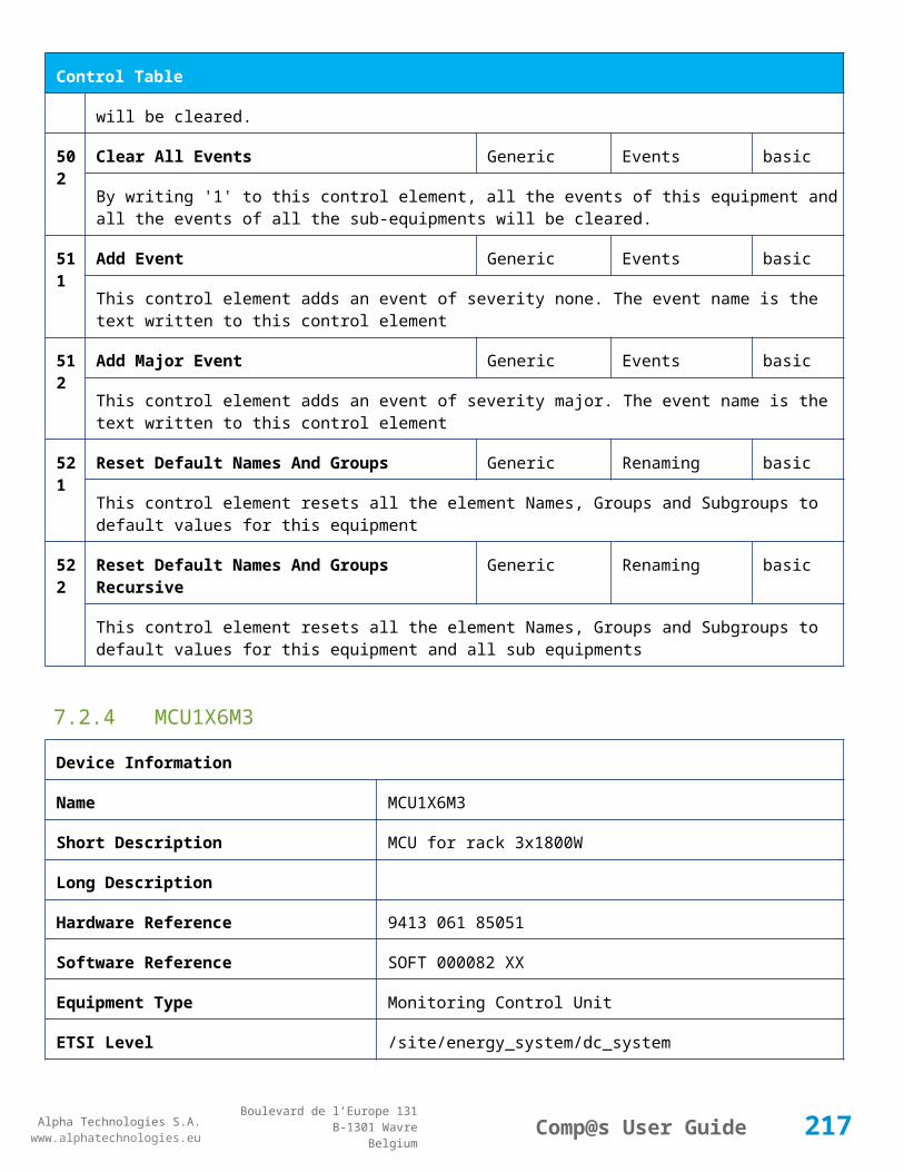
Alpha Technologies S.A.www.alphatechnologies.eu
Alpha Technologies S.A.www.alphatechnologies.eu
Comp@s User GuideBoulevard de l’Europe 131
B-1301 WavreBelgium
Control Table
The dc system must force a battery test.
4 Start Boost Mode System battery
The dc system must go in boost mode.
11 Open The LVD LVD basic
Try to open the LVD. It could not work if the LVD is electronic, and the request will be canceled after 15 sec.
12 Close The LVD LVD basic
The LVD must be closed
21 Correct Battery Current Offset Battery basic
31 Reset Battery Current Integration Battery basic
Reset the integration of the battery current.
41 Reset Last Battery Test State Battery battery
Reset the state of the last battery test. If an alarm 'Battery Last Test Failed' is set, the alarm will be cleared.
51 Save Configuration In MCU Save basic
Save configuration parameters in the MCU microcontroller. If comp@s is not present, the system will be correctly managed.
55 Set MCU Specific Configuration Id Advanced Factory basic
This control allows to reconfigure the MCU to support specific hardware configuration, with embedded distribution for example
61 Set Digital Input 4 Counter Value Digital Inputs Digital Input 4 basic
Set Counter Value
111
Invert Relay 1 State For X Seconds Relays Relay 1 basic
Generate Pulse on relay 1
112
Invert Relay 2 State For X Seconds Relays Relay 2 basic
Generate Pulse on relay 2
113
Invert Relay 3 State For X Seconds Relays Relay 3 basic
Generate Pulse on relay 3
217

Alpha Technologies S.A.www.alphatechnologies.eu
Alpha Technologies S.A.www.alphatechnologies.eu
Comp@s User GuideBoulevard de l’Europe 131
B-1301 WavreBelgium
Control Table
114
Invert Relay 4 State For X Seconds Relays Relay 4 basic
Generate Pulse on relay 4
501
Clear My Events Generic Events basic
By writing '1' to this control element, all the events of this equipment will be cleared.
502
Clear All Events Generic Events basic
By writing '1' to this control element, all the events of this equipment and all the events of all the sub-equipments will be cleared.
511
Add Event Generic Events basic
This control element adds an event of severity none. The event name is the text written to this control element
512
Add Major Event Generic Events basic
This control element adds an event of severity major. The event name is the text written to this control element
521
Reset Default Names And Groups Generic Renaming basic
This control element resets all the element Names, Groups and Subgroups to default values for this equipment
522
Reset Default Names And Groups Recursive Generic Renaming basic
This control element resets all the element Names, Groups and Subgroups to default values for this equipment and all sub equipments
7.2.6 MCU0348LP
Device Information
Name MCU0348LP
Short Description Low profile controller (1/2U high)
Long Description Low profile monitoring and control unit for CAPTIN300 line
Hardware 12NC 9413 060 10141
Equipment Type Monitoring Control Unit
ETSI Level /site/energy_system/dc_system
218

Alpha Technologies S.A.www.alphatechnologies.eu
Alpha Technologies S.A.www.alphatechnologies.eu
Comp@s User GuideBoulevard de l’Europe 131
B-1301 WavreBelgium
Description Table
Id Name Group License
1 Description Customer basic
A free text zone to write a system description
2 Reference Customer basic
A free text zone to write the customer reference of the system
11 Product Name Monitoring basic
The product name of the DC system monitoring
12 Hardware Reference Monitoring basic
The hardware reference of the DC system monitoring
14 Software Reference Monitoring asset
The serial number of the DC system monitoring
16 Serial Number Monitoring asset
The serial number of the DC system monitoring
17 Manufacturing ID Monitoring asset
The batch id of the DC system monitoring
18 Manufacturing Date Monitoring asset
The production date of the DC system monitoring
Alarm Table
Id Name Severity Type (Level)
1 DC Bus Extra Low major (6)
The bus voltage is extra low. The alarm is set when the bus voltage is lower than the configuration parameter 'DC Bus Voltage Extra Low'. There is an hysteresis on the alarm : 'DC Bus Voltage Extra Low Hysteresis'. The alarm is not activated when DC mode is BATTERY TEST
2 DC Bus Low minor (4)
The bus voltage is low. The alarm is set when the bus voltage is lower than the configuration parameter 'DC Bus Voltage Low'. There is an hysteresis on the alarm : 'DC Bus Voltage Low Hysteresis'
3 DC Bus High minor (4)
The bus voltage is high. The alarm is set when the bus voltage is higher than the configuration paramenter 'DC Bus Voltage High'. There is an hysterisis on the alarm : 'DC Bus Voltage High
219

Alpha Technologies S.A.www.alphatechnologies.eu
Alpha Technologies S.A.www.alphatechnologies.eu
Comp@s User GuideBoulevard de l’Europe 131
B-1301 WavreBelgium
Alarm Table
Hysteresis'
4 DC Bus Extra High major (6)
The bus voltage is extra high. The alarm is set when the bus voltage is higher than the configuration paramenter 'DC Bus Voltage Extra High'. There is an hysterisis on the alarm : 'DC Bus Voltage Extra High Hysteresis'
5 DC Bus Voltage Sense Failure major (6)
The DC bus voltage sense is defective. The DC bus voltage is unconnected or unconfigured.
6 Mains Failure minor (4)
The number of active rectifiers is equal to 0 and the number of rectifiers in AC failure is greater than 0.
7 Mains Partial Failure minor (4)
The number of active rectifiers is greater than 0 and the number of rectifiers in AC failure is greater than 0. Some rectifiers are in AC Failure. It may be caused by an open breaker, a real phase failure, or by a rectifier failure.
8 Mains Low warning (2)
The main voltage is low on one or more phases. No rectifier is in AC failure. If MCU master type is 30110, 3096 or 3048M6, an hysteresis _phase123Hysteresis is added to the voltage lower limit
10
One Rectifier Failure minor (4)
One rectifier must be replaced or is not powered correctly. The DC fail alarm of the rectifier is set. The number of rectifier with DC Failure is higher than 0, there is no mains failure, and the 'More Than One Rectifier Failure alarm is not set.'
11
More Than One Rectifier Failure major (6)
There is no mains failure and number of rectifier failures is greater than 1.
12
Missing Rectifiers major (6)
There is not enough rectifier according to the configuration parameter : 'Minimal Number Of Rectifier'
13
Battery Last Test Failed minor (4)
The last battery test did not succeed and was not cancelled. Maybe the battery should be replaced.
14
Battery On Discharge minor (4)
The battery is discharging. This means that the load is too high for the installed rectifiers. This alarm is inactive when the system in AC Failure or during a battery test. There is an hysteresis corresponding to battery parameter 'Is discharging current hysteresis'.
17
Battery LVD Relay Open major (6)
The battery Low Voltage Disconnector is open. On Systems without LVD_Status signal, like MCU 1848
220
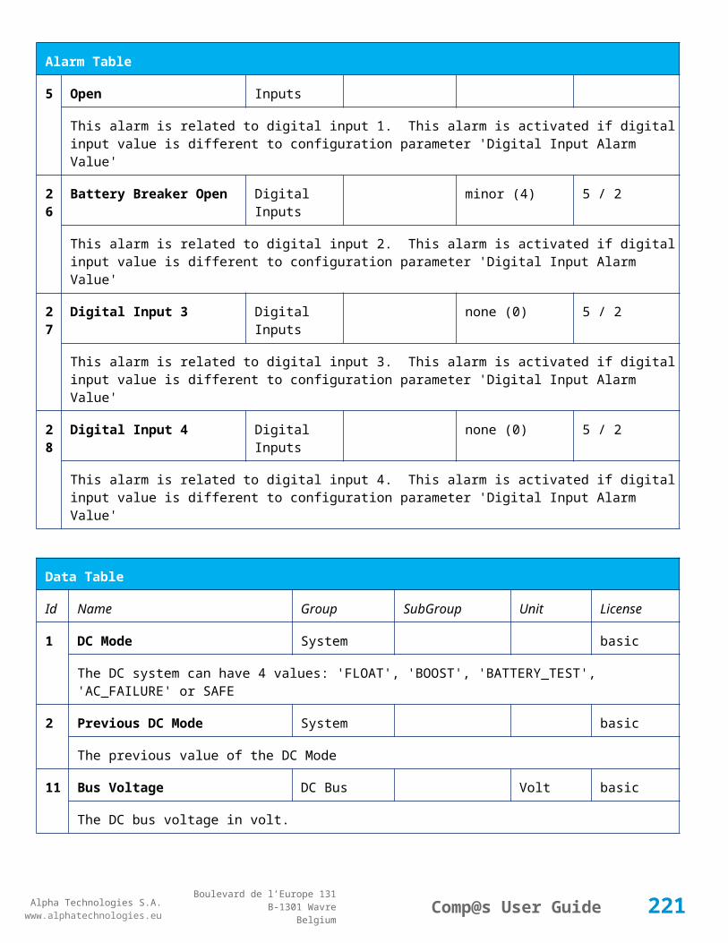
Alpha Technologies S.A.www.alphatechnologies.eu
Alpha Technologies S.A.www.alphatechnologies.eu
Comp@s User GuideBoulevard de l’Europe 131
B-1301 WavreBelgium
Alarm Table
or MCU 1x6, the alarm is present only if the signal LVD_COM asks to open the LVD
18
Battery Temperature Too High minor (4)
The temperature of the battery is too high and is greater than -600 units. There is an hysteresis corresponding to battery parameter 'Temperature hysteresis'.
19
Battery Temperature Too Low minor (4)
The temperature of the battery is too low and is greater than -600 units. There is an hysteresis corresponding to battery parameter 'Temperature hysteresis'.
20
Battery Temperature Sensor Fail minor (4)
The battery temperature sensor (NTC) value is inferior to -500 units meaning that it is not connected or defective.
21
Ambient Temperature Too High minor (4)
The ambient temperature is too high and is greater than -600 units. There is an hysteresis corresponding to parameter 'Ambiant temperature hysteresis'. This alarm is only activated on MCU master types 30110, 3096, 30125, 0024, 0948, 0548, 0348, 0948 and 3048M6.
22
Ambient Temperature Too Low minor (4)
The ambient temperature is too low and is greater than -600 units. There is an hysteresis corresponding to parameter 'Ambiant temperature hysteresis'. This alarm is only activated on MCU master types 30110, 3096, 30125, 0024, 0948, 0548, 0348, 0948 and 3048M6.
23
Ambient Temperature Sensor Fail minor (4)
The ambiant temperature sensor (NTC) value is inferior to -500 units meaning that it is not connected or defective.
25
Distribution Breaker Open major (6)
This alarm is related to digital input 1. This alarm is activated if digital input value is different to configuration parameter 'Digital Input Alarm Value'
26
Battery Breaker Open minor (4)
This alarm is related to digital input 2. This alarm is activated if digital input value is different to configuration parameter 'Digital Input Alarm Value'
27
Digital Input 3 none (0)
This alarm is related to digital input 3. This alarm is activated if digital input value is different to configuration parameter 'Digital Input Alarm Value'
28
Digital Input 4 none (0)
This alarm is related to digital input 4. This alarm is activated if digital input value is different to configuration parameter 'Digital Input Alarm Value'
221
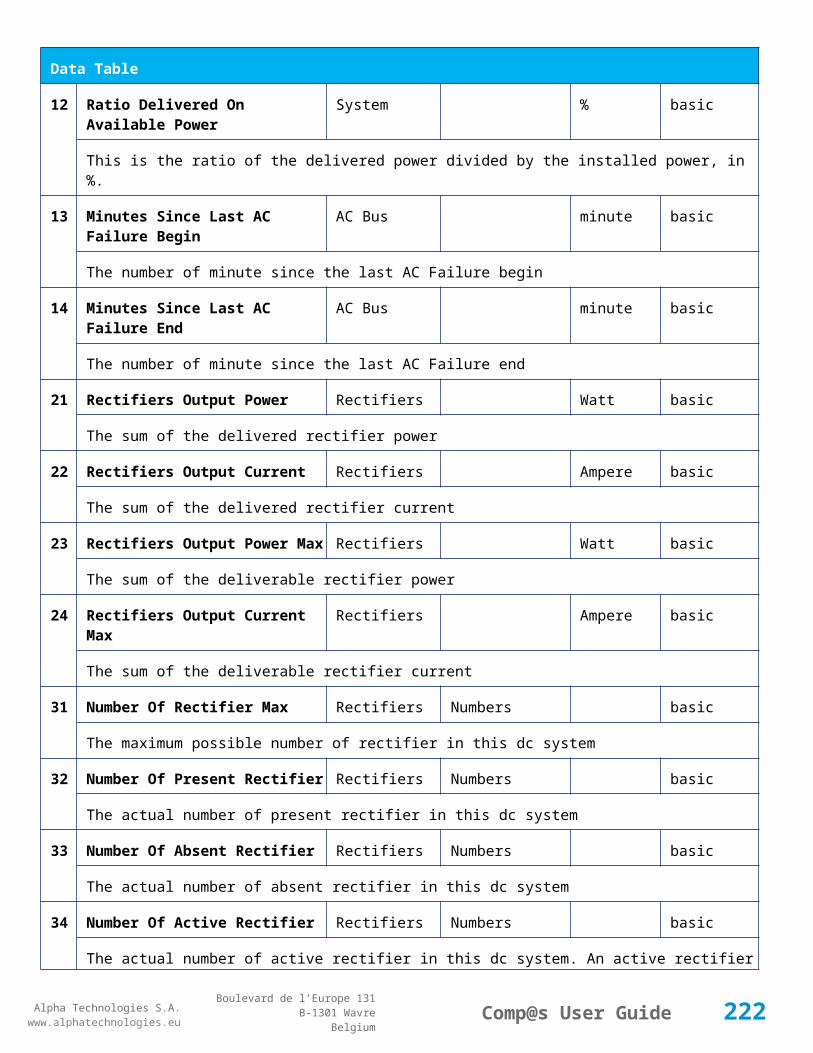
Alpha Technologies S.A.www.alphatechnologies.eu
Alpha Technologies S.A.www.alphatechnologies.eu
Comp@s User GuideBoulevard de l’Europe 131
B-1301 WavreBelgium
Alarm Table
29
Digital Input 5 none (0)
This alarm is related to digital input 5. This alarm is activated if digital input value is different to configuration parameter 'Digital Input Alarm Value'
30
Digital Input 6 none (0)
This alarm is related to digital input 6. This alarm is activated if digital input value is different to configuration parameter 'Digital Input Alarm Value'
Data Table
Id Name Group Unit License
1 DC Mode General basic
The DC system can have 4 values: 'FLOAT', 'BOOST', 'BATTERY_TEST', 'AC_FAILURE' or SAFE
2 Previous DC Mode General basic
The previous value of the DC Mode
11 Bus Voltage General Volt basic
The DC bus voltage in volt.
12 Ratio Delivered On Available Power General % basic
This is the ratio of the delivered power divided by the installed power, in %.
13 Minutes Since Last AC Failure Begin General minute basic
The number of minute since the last AC Failure begin
14 Minutes Since Last AC Failure End General minute basic
The number of minute since the last AC Failure end
21 Rectifiers Output Power Rectifiers Watt basic
The sum of the delivered rectifier power
22 Rectifiers Output Current Rectifiers Ampere basic
The sum of the delivered rectifier current
23 Rectifiers Output Power Max Rectifiers Watt basic
The sum of the deliverable rectifier power
24 Rectifiers Output Current Max Rectifiers Ampere basic
222

Alpha Technologies S.A.www.alphatechnologies.eu
Alpha Technologies S.A.www.alphatechnologies.eu
Comp@s User GuideBoulevard de l’Europe 131
B-1301 WavreBelgium
Data Table
The sum of the deliverable rectifier current
31 Number Of Rectifier Max Rectifiers basic
The maximum possible number of rectifier in this dc system
32 Number Of Present Rectifier Rectifiers basic
The actual number of present rectifier in this dc system
33 Number Of Absent Rectifier Rectifiers basic
The actual number of absent rectifier in this dc system
34 Number Of Active Rectifier Rectifiers basic
The actual number of active rectifier in this dc system. An active rectifier is a rectifier which is present, DC OK, AC OK and not in remote off.
35 Number Of AC-Fail Rectifier Rectifiers basic
The actual number or rectifier in AC Failure.
36 Number Of DC-Fail Rectifier Rectifiers basic
The actual number or rectifier with DC Failure.
37 Number Of Remote Off Rectifier Rectifiers basic
The actual number or rectifier in remote off.
38 Number Of Over Temperature Rectifier Rectifiers basic
The actual number or rectifier in OVer Temperature.
51 Load Power Load Watt basic
Estimation of the load power consumption
52 Load Current Load Ampere basic
Estimation of the load current consumption
61 Battery Input Current Battery Ampere basic
Measurement of the battery input current. A negative value means that the battery is discharging
62 Battery Input Power Battery Watt basic
Measurement of the battery input power. A negative value means that the battery is discharging
71 Battery Temperature Battery degree C basic
The battery temperature
223

Alpha Technologies S.A.www.alphatechnologies.eu
Alpha Technologies S.A.www.alphatechnologies.eu
Comp@s User GuideBoulevard de l’Europe 131
B-1301 WavreBelgium
Data Table
72 Battery Test State Battery basic
This is about the result of the last battery test. 9 values are possible : NEVER_TESTED, SUCCESS, ON_GOING, FAILED_TIMEOUT, FAILED_VBUS_TOO_LOW, FAILED_LOAD_TOO_LOW, FAILED_AC_FAILURE, FAILED_CANCELED, FAILED_LVD_OPENED
73 Battery Test Discharged Capacity Battery % basic
This is the battery capacity, in percent, discharged during the last battery test. This value is updated at the end of the battery test.
74 Battery Test Discharged Capacity Ah Battery Ah basic
This is the battery capacity, in ampere hour, discharged during the last battery test. This value is updated at the end of the battery test.
75 Battery Test Final Voltage Battery % basic
This is the bus voltage at the end of the last battery test. This value is updated at the end of the battery test.
81 Previous Battery Test State Battery basic
The result of the previous battery test
82 Minutes Since Last Test Battery Battery basic
The number of minute without battery test
91 Battery Charge Capacity Battery % basic
The battery charge capacity, calculated by integration of the current.
92 Calculated Autonomy Battery minute basic
Calculation of the remaining autonomy
93 Battery Current Integration As Battery As basic
Actual value of the integration of the current, in Ampere * second
94 Battery Current Integration Ah Battery Ah basic
Actual value of the integration of the current, in Ampere * hour
101
LVD State LVD basic
Actual state of the LVD
121
Efficiency Optimized Number Of Rectifier Asset Data asset
The optimal number of ON rectifier for Efficiency Optimization
12 System Loss Without Optimisation Asset Data Watt asset
224

Alpha Technologies S.A.www.alphatechnologies.eu
Alpha Technologies S.A.www.alphatechnologies.eu
Comp@s User GuideBoulevard de l’Europe 131
B-1301 WavreBelgium
Data Table
2 The optimal number of ON rectifier for Efficiency Optimization
123
System Loss With Optimisation Asset Data Watt asset
The optimal number of ON rectifier for Efficiency Optimization
151
Ambient Temperature Sensors degree C basic
The ambiant temperature (second temperature sense)
204
Digital Input 4 Counter Sensors basic
The counter value of the digital input 4.
Config Table
Id Name Group Unit Range: Min/Max (default)
License
1 DC Bus Float Voltage at 25 degC
Bus Voltage Volt 40/60 (54) basic
The floating dc bus voltage of the system at 25 Celsius degree
2 DC Bus Voltage Extra Low Bus Voltage Volt 40/60 (45) basic
The bus voltage under which the alarm 'DC Bus Voltage Extra Low' is set.
3 DC Bus Voltage Extra Low Hysteresis
Bus Voltage Volt 0/5 (1) basic
The voltage hysteresis on the alarm 'DC Bus Voltage Extra Low'.
4 DC Bus Voltage Low Bus Voltage Volt 40/60 (48) basic
The bus voltage under which the alarm 'DC Bus Voltage Low' is set.
5 DC Bus Voltage Low Hysteresis
Bus Voltage Volt 0/5 (0.5) basic
The voltage hysteresis on the alarm 'DC Bus Voltage Low
6 DC Bus Voltage High Bus Voltage Volt 40/60 (56.5) basic
The bus voltage over which the alarm 'DC Bus Voltage High' is set.
7 DC Bus Voltage High Hysteresis
Bus Voltage Volt 0/5 (0.5) basic
The voltage hysteresis on the alarm 'DC Bus Voltage High
8 DC Bus Voltage Extra High Bus Voltage Volt 40/60 (58) basic
225
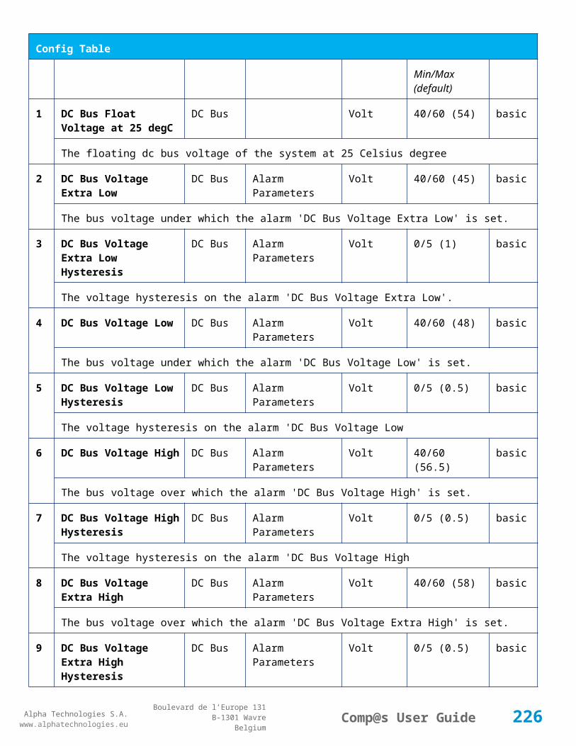
Alpha Technologies S.A.www.alphatechnologies.eu
Alpha Technologies S.A.www.alphatechnologies.eu
Comp@s User GuideBoulevard de l’Europe 131
B-1301 WavreBelgium
Config Table
The bus voltage over which the alarm 'DC Bus Voltage Extra High' is set.
9 DC Bus Voltage Extra High Hysteresis
Bus Voltage Volt 0/5 (0.5) basic
The voltage hysteresis on the alarm 'DC Bus Voltage Extra High
10 LVD Disconnect Voltage Bus Voltage Volt 0/50 (43.2) basic
The dc bus voltage under which the battery must be disconnected of the bus. This allows preserving the battery life. The load will be unpowered.
11 LVD Disconnect Delay Bus Voltage second 1/2000 (1) basic
The delay in second before disconnecting the battery if the dc bus voltage is under the configured disconnected voltage. This avoids disconnection during a low bus transient.
21 Temperature Compensation Slope
Temperature Compensation
mV/degree -1000/0 (-72) basic
The slope of the battery temperature compensation in mv/degree. For a 48V system, -72mV/degree is often used.
22 Maximum Positive Temperature Compensation
Temperature Compensation
Volt 0/10 (3) basic
The maximal allowed positive compensation.
23 Maximum Negative Temperature Compensation
Temperature Compensation
Volt -10/0 (-3) basic
The maximal allowed negative compensation.
25 Minimal Number Of Present Rectifiers
Rectifiers 0/100 (0) basic
The minimal number of rectifier which must be present. If there is less present rectifiers, the alarm 'Missing Rectifiers' is set.
26 Rectifier Model Rectifiers basic
The rectifier model
27 Forced Remote Off Rectifers Rectifiers basic
A list of rectifier which are forced in remote off. The id of the rectifier must be coma separated. Ex: 1,3 will maintain rectifier 1 and 3 off.
31 Battery Charge Current Limit Battery Ampere 0.5/1000 (1000) basic
The maximal battery current when the battery is charging. The monitoring regulates the bus voltage in order to satisfy this condition. This parameter is often equal to the nominal battery capacity divided by 10.
226

Alpha Technologies S.A.www.alphatechnologies.eu
Alpha Technologies S.A.www.alphatechnologies.eu
Comp@s User GuideBoulevard de l’Europe 131
B-1301 WavreBelgium
Config Table
32 Battery String Capacity Battery Ah 3/1000 (100) basic
The battery capacity in Ah.
33 Battery Temperature Low Battery degree C -100/20 (0) basic
The temperature under which the alarm 'Battery Temperature Too Low' must be set.
34 Battery Temperature High Battery degree C 5/100 (40) basic
The temperature over which the alarm 'Battery Temperature Too High' must be set.
35 Battery Temperature Hysteresis
Battery degree C 0/10 (2) basic
The hysteresis on the 'Battery Temperature Too High' and 'Battery Temperature Too Low' alarms.
36 Minimal Current For Discharging Alarm
Battery Ampere 0/1000 (0.5) basic
The minimal discharging current to set the 'Battery On Discharge' alarm.
37 Current Hysteresis For Discharging Alarm
Battery Ampere 0/50 (0.2) basic
The hysteresis on the 'Battery On Discharge' alarm.
51 Boost Automatic Boost False/False (False) battery
The boost mode must be automatically after the fact that during a mains failure, the bus voltage went under the configured 'Boost Activation Low Voltage'. This allows charging the battery faster.
52 Boost Activation Low Voltage Boost Volt 43/50 (46) battery
The voltage under which the boost mode can be activated.
53 Boost Termination Voltage Boost Volt 50/58 (56.4) battery
The voltage over which the system must go back to floating mode.
54 Boost Termination Current Boost Ampere 0/100 (2) battery
The battery charging current under which the system must go back to floating mode.
55 Boost Termination Time Boost minute 10/240 (120) battery
The time in minute after which the system must go back in floating mode.
70 Battery Test End Voltage Battery Test Volt 30/60 (46) battery
The voltage at which any battery test must be stopped.
71 Battery Test Discharge Ratio Battery Test % 0/100 (0) battery
227
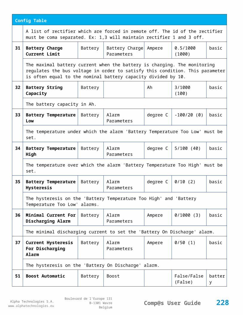
Alpha Technologies S.A.www.alphatechnologies.eu
Alpha Technologies S.A.www.alphatechnologies.eu
Comp@s User GuideBoulevard de l’Europe 131
B-1301 WavreBelgium
Config Table
The ratio of the battery capacity to discharge. If 30 is set, 30% of the battery will be discharged during the test
72 Battery Test Interval Battery Test day 0/3000 (0) battery
The number of days between two automatically started battery test. If this parameter is set to 0, the battery test is not started automatically. The user can remotely or locally start or force this test.
73 Battery Test Discharge Current
Battery Test Ampere 0.5/100 (1000) battery
The current at which the battery must be discharged during a battery test. The monitoring regulates the bus voltage in order to satisfy this condition. The load current must be of course higher than this parameter.
74 Battery Test Minimal Discharge Current
Battery Test Ampere 0.2/90 (2) battery
The battery current under which the battery test must be stopped because the load is too low.
75 Battery Test Time Out Battery Test minute 1/5000 (10) battery
The timeout in minute after which the battery test must be stopped.
76 Battery Test Requested Minutes Without Mains Failure
Battery Test minute 0/5000 (1440) battery
The minimal time in minute without mains failure in order to allow a battery start. This parameter is not taken into account when the battery test is forced.
83 Smart Energy Boolean Condition
Smart Energy 121-125 asset
This is the boolean condition which allows or not to automatically optimize the number of rectifier in remote off.
86 Battery LVD Node Id LVD True/False (False) basic
This is a list of the node id of the Smart Electronic LVDs, coma separated
91 Digital Input 1 Name Digital Inputs Distribution Breaker Open
basic
The name of the digital input 1
92 Digital Input 1 Normally Closed
Digital Inputs True/False (True) basic
True/False value defining if the digital input 1 is normally closed. If this digital input is not in this default state, the related alarm is set.
93 Digital Input 2 Name Digital Inputs Battery Breaker Open
basic
228

Alpha Technologies S.A.www.alphatechnologies.eu
Alpha Technologies S.A.www.alphatechnologies.eu
Comp@s User GuideBoulevard de l’Europe 131
B-1301 WavreBelgium
Config Table
The name of the digital input 2
94 Digital Input 2 Normally Closed
Digital Inputs True/False (True) basic
True/False value defining if the digital input 2 is normally closed. If this digital input is not in this default state, the related alarm is set.
95 Digital Input 3 Name Digital Inputs Digital Input 3 basic
The name of the digital input 3
96 Digital Input 3 Normally Closed
Digital Inputs True/False (True) basic
True/False value defining if the digital input 3 is normally closed. If this digital input is not in this default state, the related alarm is set.
97 Digital Input 4 Name Digital Inputs Digital Input 4 basic
The name of the digital input 4
98 Digital Input 4 Normally Closed
Digital Inputs True/False (True) basic
True/False value defining if the digital input 4 is normally closed. If this digital input is not in this default state, the related alarm is set.
99 Digital Input 5 Name Digital Inputs Digital Input 5 basic
The name of the digital input 5
100
Digital Input 5 Normally Closed
Digital Inputs True/False (True) basic
True/False value defining if the digital input 5 is normally closed. If this digital input is not in this default state, the related alarm is set.
101
Digital Input 6 Name Digital Inputs Digital Input 6 basic
The name of the digital input 6
102
Digital Input 6 Normally Closed
Digital Inputs True/False (True) basic
True/False value defining if the digital input 6 is normally closed. If this digital input is not in this default state, the related alarm is set.
111
Dry Alarm 1 Alternative Boolean Condition
Dry Alarms False plc
Another Boolean condition to activate the dry alarm relay 1. The way to define boolean condition is detailed in the PLC chapter.
229

Alpha Technologies S.A.www.alphatechnologies.eu
Alpha Technologies S.A.www.alphatechnologies.eu
Comp@s User GuideBoulevard de l’Europe 131
B-1301 WavreBelgium
Config Table
112
Dry Alarm 2 Alternative Boolean Condition
Dry Alarms False plc
Another Boolean condition to activate the dry alarm relay 2. The way to define boolean condition is detailed in the PLC chapter.
113
Dry Alarm 3 Alternative Boolean Condition
Dry Alarms False plc
Another Boolean condition to activate the dry alarm relay 3. The way to define boolean condition is detailed in the PLC chapter.
114
Dry Alarm 4 Alternative Boolean Condition
Dry Alarms False plc
Another Boolean condition to activate the dry alarm relay 4. The way to define boolean condition is detailed in the PLC chapter.
131
Ambient Temperature Low Sensors degree C basic
The temperature under which the alarm 'Ambiant Temperature Too Low' must be set.
132
Ambient Temperature High Sensors degree C basic
The temperature under which the alarm 'Ambiant Temperature Too Low' must be set.
133
Ambient Temperature Hysteresis
Sensors degree C basic
The hysteresis on the 'Battery Temperature Too High' and 'Battery Temperature Too Low' alarms.
521
Read Access User Numbers Allowed Users (1,2,3,4,5) basic
The list of the user numbers which have read access to this equipment. The user numbers are coma separated. The accepted user id are 1,2,3,4 and 5. Ex: 1,3,4
522
Write Access User Numbers Allowed Users () basic
The list of the user numbers which have write access to this equipment. This means that these users can modify the configuration element, the alarm settings and use the control elements. The user numbers are coma separated. The accepted user ids are 1,2,3,4 and 5. Ex: 1,3,4
601
Event Table Length Event 10/4000 (100) basic
The maximum length of the table. The value must be comprised between 10 and 4000
611
SNMP Trap Targets IP Event 192.168.45.1 basic
One or multiple target IP to send traps, coma separated. Ex: 130.145.23.1, 130.23.12.45
612
Minimal Event Severity For Traps
Event (none) basic
This is the minimal severity of the event to send a SNMP trap
230
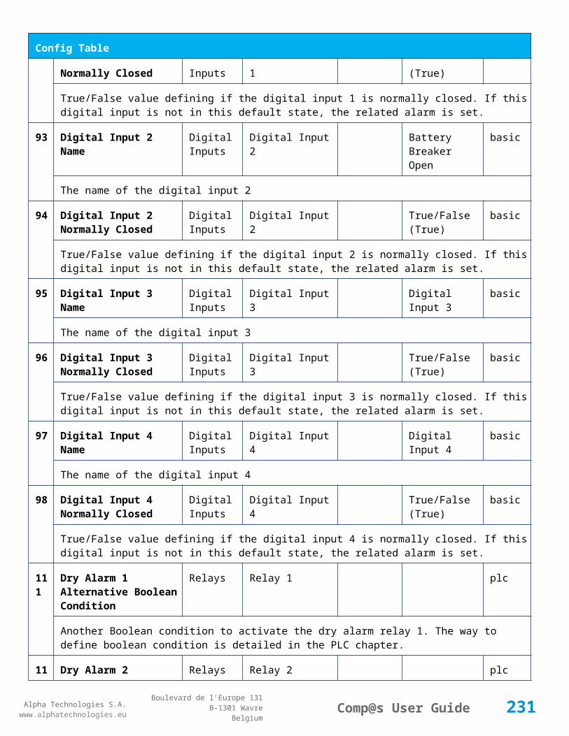
Alpha Technologies S.A.www.alphatechnologies.eu
Alpha Technologies S.A.www.alphatechnologies.eu
Comp@s User GuideBoulevard de l’Europe 131
B-1301 WavreBelgium
Config Table
651
XML Events Primary Post URL
Event basic
This is the first URL at which the events related to this equipment must be posted. The XML ETSI standard is used in the posted data content.
652
XML Events Primary Post Login
Event basic
The login which must be used when posting events to the primary server
653
XML Events Primary Post Password
Event basic
The password which must be used when posting events to the primary server
661
XML Events Secondary Post URL
Event basic
This is the second URL at which the events related to this equipment must be posted. The XML ETSI standard is used in the posted data content. This allows having redundancy with the management server.
662
XML Events Secondary Post Login
Event basic
The login which must be used when posting events to the secondary server
663
XML Events Secondary Post Password
Event basic
The password which must be used when posting events to the secondary server
901
Number Of PLC Data PLC (0) plc
The number of PLC data. Every equipment can manage up to 20 user programmable data. Data elements are automatically added in the data table. Configuration parameters are added to set the PLC Data Name and the PLC Data Mathematical calculation. In order to use these functionalities, you need a license with the 'PLC' module
902
Number Of PLC Alarm PLC (0) plc
The number of PLC alarm. Every equipment can manage up to 20 user programmable alarms. Alarm elements are automatically added in the alarm table. The alarm parameters are added to set the PLC Alarm Name and the PLC Alarm Boolean condition. In order to use these functionalities, you need a licence with the 'PLC' module
Control Table
Id Name Group License
1 Back To Float DC Mode basic
231
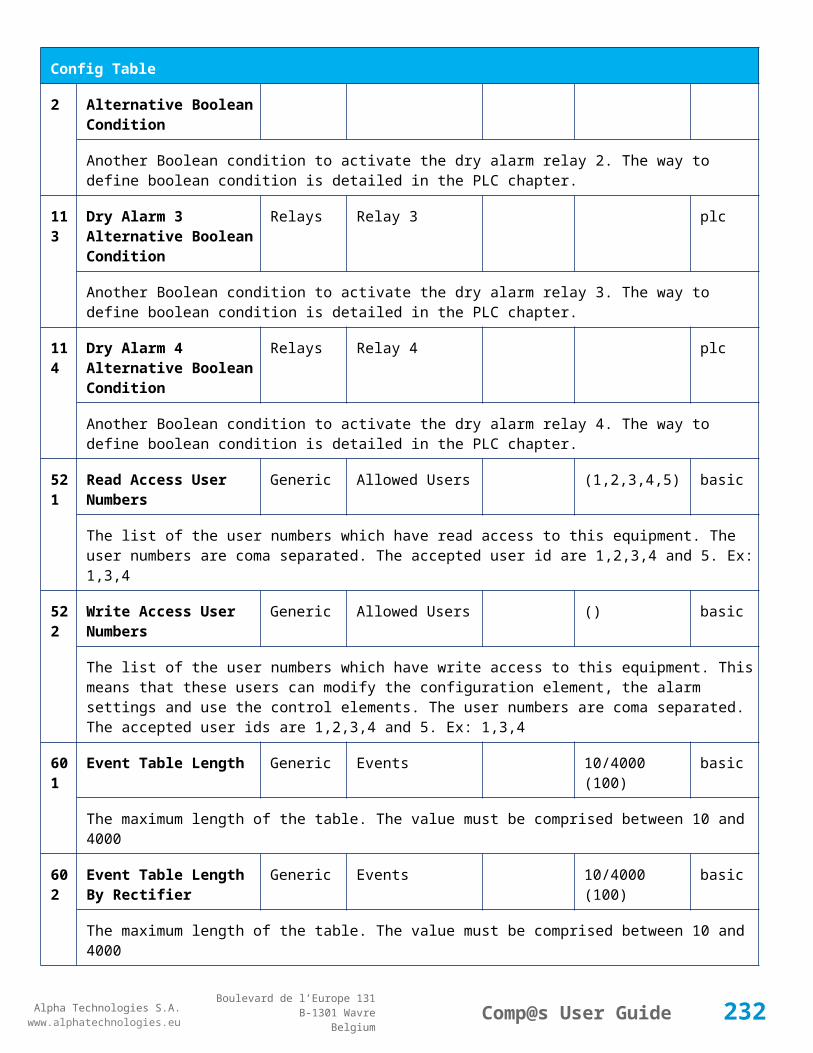
Alpha Technologies S.A.www.alphatechnologies.eu
Alpha Technologies S.A.www.alphatechnologies.eu
Comp@s User GuideBoulevard de l’Europe 131
B-1301 WavreBelgium
Control Table
The dc system must go back in floating mode.
2 Start Battery Test DC Mode battery
The dc system must start a battery test.
3 Force Battery Test DC Mode battery
The dc system must force a battery test.
4 Start Boost Mode DC Mode battery
The dc system must go in boost mode.
11 Open The LVD LVD basic
The LVD must be opened
12 Close The LVD LVD basic
The LVD must be closed
21 Correct Battery Current Offset Battery basic
No information
31 Reset Battery Current Integration Battery basic
Reset the integration of the battery current.
41 Reset Last Battery Test State Battery battery
Reset the state of the last battery test. If an alarm 'Battery Last Test Failed' is set, the alarm will be cleared.
51 Save Configuration In MCU Save basic
Save configuration parameters in the MCU microcontroller. If comp@s is not present, the system will be correctly managed.
61 Set Digital Input 4 Counter Value Counters basic
Set Counter Value
501
Clear My Events Event basic
By writing '1' to this control element, all the events of this equipment will be cleared.
502
Clear All Events Event basic
By writing '1' to this control element, all the events of this equipment and all the events of all the sub-equipments will be cleared.
51 Add Event Event basic
232

Alpha Technologies S.A.www.alphatechnologies.eu
Alpha Technologies S.A.www.alphatechnologies.eu
Comp@s User GuideBoulevard de l’Europe 131
B-1301 WavreBelgium
Control Table
1 This control element adds an event of severity none. The event name is the text written to this control element
512
Add Major Event Event basic
This control element adds an event of severity major. The event name is the text written to this control element
521
Reset Default Names Event basic
This control element adds an event of severity major. The event name is the text written to this control element
7.2.7 MCU0348M4
Device Information
Name MCU0348M4
Short Description
1U high controller with LCD display
Long Description
Monitoring and control unit, 1U high with LCD display, USB and Ethernet port - Captin300 line
Hardware 12NC 9413 060 10131
Equipment Type Monitoring Control Unit
ETSI Level /site/energy_system/dc_system
Description Table
Id Name Group License
1 Description Customer basic
A free text zone to write a system description
2 Reference Customer basic
A free text zone to write the customer reference of the system
11 Product Name Monitoring basic
The product name of the DC system monitoring
12 Hardware Reference Monitoring basic
The hardware reference of the DC system monitoring
233

Alpha Technologies S.A.www.alphatechnologies.eu
Alpha Technologies S.A.www.alphatechnologies.eu
Comp@s User GuideBoulevard de l’Europe 131
B-1301 WavreBelgium
Description Table
14 Software Reference Monitoring asset
The serial number of the DC system monitoring
16 Serial Number Monitoring asset
The serial number of the DC system monitoring
17 Manufacturing ID Monitoring asset
The batch id of the DC system monitoring
18 Manufacturing Date Monitoring asset
The production date of the DC system monitoring
Alarm Table
Id Name Severity Type (Level)
1 DC Bus Extra Low major (6)
The bus voltage is extra low. The alarm is set when the bus voltage is lower than the configuration parameter 'DC Bus Voltage Extra Low'. There is an hysteresis on the alarm : 'DC Bus Voltage Extra Low Hysteresis'. The alarm is not activated when DC mode is BATTERY TEST
2 DC Bus Low minor (4)
The bus voltage is low. The alarm is set when the bus voltage is lower than the configuration parameter 'DC Bus Voltage Low'. There is an hysteresis on the alarm : 'DC Bus Voltage Low Hysteresis'
3 DC Bus High minor (4)
The bus voltage is high. The alarm is set when the bus voltage is higher than the configuration paramenter 'DC Bus Voltage High'. There is an hysterisis on the alarm : 'DC Bus Voltage High Hysteresis'
4 DC Bus Extra High major (6)
The bus voltage is extra high. The alarm is set when the bus voltage is higher than the configuration paramenter 'DC Bus Voltage Extra High'. There is an hysterisis on the alarm : 'DC Bus Voltage Extra High Hysteresis'
5 DC Bus Voltage Sense Failure major (6)
The DC bus voltage sense is defective. The DC bus voltage is unconnected or unconfigured.
6 Mains Failure minor (4)
The number of active rectifiers is equal to 0 and the number of rectifiers in AC failure is greater than 0.
7 Mains Partial Failure minor (4)
234
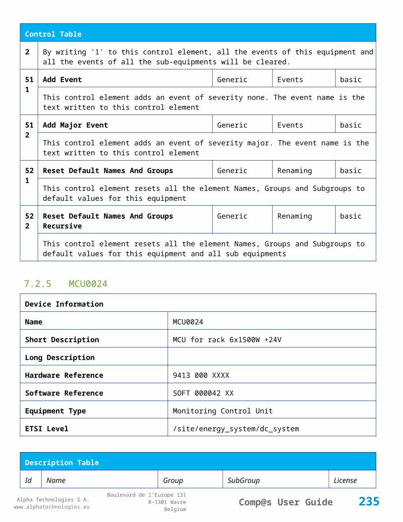
Alpha Technologies S.A.www.alphatechnologies.eu
Alpha Technologies S.A.www.alphatechnologies.eu
Comp@s User GuideBoulevard de l’Europe 131
B-1301 WavreBelgium
Alarm Table
The number of active rectifiers is greater than 0 and the number of rectifiers in AC failure is greater than 0. Some rectifiers are in AC Failure. It may be caused by an open breaker, a real phase failure, or by a rectifier failure.
8 Mains Low warning (2)
The main voltage is low on one or more phases. No rectifier is in AC failure. If MCU master type is 30110, 3096 or 3048M6, an hysteresis _phase123Hysteresis is added to the voltage lower limit
10
One Rectifier Failure minor (4)
One rectifier must be replaced or is not powered correctly. The DC fail alarm of the rectifier is set. The number of rectifier with DC Failure is higher than 0, there is no mains failure, and the 'More Than One Rectifier Failure alarm is not set.'
11
More Than One Rectifier Failure major (6)
There is no mains failure and number of rectifier failures is greater than 1.
12
Missing Rectifiers major (6)
There is not enough rectifier according to the configuration parameter : 'Minimal Number Of Rectifier'
13
Battery Last Test Failed minor (4)
The last battery test did not succeed and was not cancelled. Maybe the battery should be replaced.
14
Battery On Discharge minor (4)
The battery is discharging. This means that the load is too high for the installed rectifiers. This alarm is inactive when the system in AC Failure or during a battery test. There is an hysteresis corresponding to battery parameter 'Is discharging current hysteresis'.
17
Battery LVD Relay Open major (6)
The battery Low Voltage Disconnector is open. On Systems without LVD_Status signal, like MCU 1848 or MCU 1x6, the alarm is present only if the signal LVD_COM asks to open the LVD
18
Battery Temperature Too High minor (4)
The temperature of the battery is too high and is greater than -600 units. There is an hysteresis corresponding to battery parameter 'Temperature hysteresis'.
19
Battery Temperature Too Low minor (4)
The temperature of the battery is too low and is greater than -600 units. There is an hysteresis corresponding to battery parameter 'Temperature hysteresis'.
20
Battery Temperature Sensor Fail minor (4)
The battery temperature sensor (NTC) value is inferior to -500 units meaning that it is not connected or defective.
2 Ambient Temperature Too High minor (4)
235

Alpha Technologies S.A.www.alphatechnologies.eu
Alpha Technologies S.A.www.alphatechnologies.eu
Comp@s User GuideBoulevard de l’Europe 131
B-1301 WavreBelgium
Alarm Table
1 The ambient temperature is too high and is greater than -600 units. There is an hysteresis corresponding to parameter 'Ambiant temperature hysteresis'. This alarm is only activated on MCU master types 30110, 3096, 30125, 0024, 0948, 0548, 0348, 0948 and 3048M6.
22
Ambient Temperature Too Low minor (4)
The ambient temperature is too low and is greater than -600 units. There is an hysteresis corresponding to parameter 'Ambiant temperature hysteresis'. This alarm is only activated on MCU master types 30110, 3096, 30125, 0024, 0948, 0548, 0348, 0948 and 3048M6.
23
Ambient Temperature Sensor Fail minor (4)
The ambiant temperature sensor (NTC) value is inferior to -500 units meaning that it is not connected or defective.
25
Distribution Breaker Open major (6)
This alarm is related to digital input 1. This alarm is activated if digital input value is different to configuration parameter 'Digital Input Alarm Value'
26
Battery Breaker Open minor (4)
This alarm is related to digital input 2. This alarm is activated if digital input value is different to configuration parameter 'Digital Input Alarm Value'
27
Digital Input 3 none (0)
This alarm is related to digital input 3. This alarm is activated if digital input value is different to configuration parameter 'Digital Input Alarm Value'
28
Digital Input 4 none (0)
This alarm is related to digital input 4. This alarm is activated if digital input value is different to configuration parameter 'Digital Input Alarm Value'
29
Digital Input 5 none (0)
This alarm is related to digital input 5. This alarm is activated if digital input value is different to configuration parameter 'Digital Input Alarm Value'
30
Digital Input 6 none (0)
This alarm is related to digital input 6. This alarm is activated if digital input value is different to configuration parameter 'Digital Input Alarm Value'
Data Table
Id Name Group Unit License
1 DC Mode General basic
The DC system can have 4 values: 'FLOAT', 'BOOST', 'BATTERY_TEST', 'AC_FAILURE' or SAFE
236

Alpha Technologies S.A.www.alphatechnologies.eu
Alpha Technologies S.A.www.alphatechnologies.eu
Comp@s User GuideBoulevard de l’Europe 131
B-1301 WavreBelgium
Data Table
2 Previous DC Mode General basic
The previous value of the DC Mode
11 Bus Voltage General Volt basic
The DC bus voltage in volt.
12 Ratio Delivered On Available Power General % basic
This is the ratio of the delivered power divided by the installed power, in %.
13 Minutes Since Last AC Failure Begin General minute basic
The number of minute since the last AC Failure begin
14 Minutes Since Last AC Failure End General minute basic
The number of minute since the last AC Failure end
21 Rectifiers Output Power Rectifiers Watt basic
The sum of the delivered rectifier power
22 Rectifiers Output Current Rectifiers Ampere basic
The sum of the delivered rectifier current
23 Rectifiers Output Power Max Rectifiers Watt basic
The sum of the deliverable rectifier power
24 Rectifiers Output Current Max Rectifiers Ampere basic
The sum of the deliverable rectifier current
31 Number Of Rectifier Max Rectifiers basic
The maximum possible number of rectifier in this dc system
32 Number Of Present Rectifier Rectifiers basic
The actual number of present rectifier in this dc system
33 Number Of Absent Rectifier Rectifiers basic
The actual number of absent rectifier in this dc system
34 Number Of Active Rectifier Rectifiers basic
The actual number of active rectifier in this dc system. An active rectifier is a rectifier which is present, DC OK, AC OK and not in remote off.
35 Number Of AC-Fail Rectifier Rectifiers basic
237
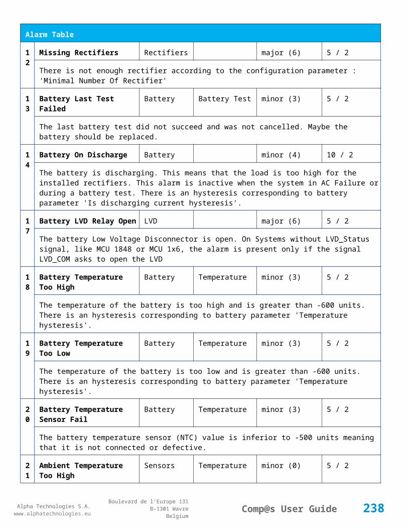
Alpha Technologies S.A.www.alphatechnologies.eu
Alpha Technologies S.A.www.alphatechnologies.eu
Comp@s User GuideBoulevard de l’Europe 131
B-1301 WavreBelgium
Data Table
The actual number or rectifier in AC Failure.
36 Number Of DC-Fail Rectifier Rectifiers basic
The actual number or rectifier with DC Failure.
37 Number Of Remote Off Rectifier Rectifiers basic
The actual number or rectifier in remote off.
38 Number Of Over Temperature Rectifier Rectifiers basic
The actual number or rectifier in OVer Temperature.
51 Load Power Load Watt basic
Estimation of the load power consumption
52 Load Current Load Ampere basic
Estimation of the load current consumption
61 Battery Input Current Battery Ampere basic
Measurement of the battery input current. A negative value means that the battery is discharging
62 Battery Input Power Battery Watt basic
Measurement of the battery input power. A negative value means that the battery is discharging
71 Battery Temperature Battery degree C basic
The battery temperature
72 Battery Test State Battery basic
This is about the result of the last battery test. 9 values are possible : NEVER_TESTED, SUCCESS, ON_GOING, FAILED_TIMEOUT, FAILED_VBUS_TOO_LOW, FAILED_LOAD_TOO_LOW, FAILED_AC_FAILURE, FAILED_CANCELED, FAILED_LVD_OPENED
73 Battery Test Discharged Capacity Battery % basic
This is the battery capacity, in percent, discharged during the last battery test. This value is updated at the end of the battery test.
74 Battery Test Discharged Capacity Ah Battery Ah basic
This is the battery capacity, in ampere hour, discharged during the last battery test. This value is updated at the end of the battery test.
75 Battery Test Final Voltage Battery % basic
This is the bus voltage at the end of the last battery test. This value is updated at the end of the battery test.
238

Alpha Technologies S.A.www.alphatechnologies.eu
Alpha Technologies S.A.www.alphatechnologies.eu
Comp@s User GuideBoulevard de l’Europe 131
B-1301 WavreBelgium
Data Table
81 Previous Battery Test State Battery basic
The result of the previous battery test
82 Minutes Since Last Test Battery Battery basic
The number of minute without battery test
91 Battery Charge Capacity Battery % basic
The battery charge capacity, calculated by integration of the current.
92 Calculated Autonomy Battery minute basic
Calculation of the remaining autonomy
93 Battery Current Integration As Battery As basic
Actual value of the integration of the current, in Ampere * second
94 Battery Current Integration Ah Battery Ah basic
Actual value of the integration of the current, in Ampere * hour
101
LVD State LVD basic
Actual state of the LVD
121
Efficiency Optimized Number Of Rectifier Asset Data asset
The optimal number of ON rectifier for Efficiency Optimization
122
System Loss Without Optimisation Asset Data Watt asset
The optimal number of ON rectifier for Efficiency Optimization
123
System Loss With Optimisation Asset Data Watt asset
The optimal number of ON rectifier for Efficiency Optimization
151
Ambient Temperature Sensors degree C basic
The ambiant temperature (second temperature sense)
204
Digital Input 4 Counter Sensors basic
The counter value of the digital input 4.
Config Table
Id Name Group Unit Range: Min/Max (default)
License
239

Alpha Technologies S.A.www.alphatechnologies.eu
Alpha Technologies S.A.www.alphatechnologies.eu
Comp@s User GuideBoulevard de l’Europe 131
B-1301 WavreBelgium
Config Table
1 DC Bus Float Voltage at 25 degC
Bus Voltage Volt 40/60 (54) basic
The floating dc bus voltage of the system at 25 Celsius degree
2 DC Bus Voltage Extra Low Bus Voltage Volt 40/60 (45) basic
The bus voltage under which the alarm 'DC Bus Voltage Extra Low' is set.
3 DC Bus Voltage Extra Low Hysteresis
Bus Voltage Volt 0/5 (1) basic
The voltage hysteresis on the alarm 'DC Bus Voltage Extra Low'.
4 DC Bus Voltage Low Bus Voltage Volt 40/60 (48) basic
The bus voltage under which the alarm 'DC Bus Voltage Low' is set.
5 DC Bus Voltage Low Hysteresis
Bus Voltage Volt 0/5 (0.5) basic
The voltage hysteresis on the alarm 'DC Bus Voltage Low
6 DC Bus Voltage High Bus Voltage Volt 40/60 (56.5) basic
The bus voltage over which the alarm 'DC Bus Voltage High' is set.
7 DC Bus Voltage High Hysteresis
Bus Voltage Volt 0/5 (0.5) basic
The voltage hysteresis on the alarm 'DC Bus Voltage High
8 DC Bus Voltage Extra High Bus Voltage Volt 40/60 (58) basic
The bus voltage over which the alarm 'DC Bus Voltage Extra High' is set.
9 DC Bus Voltage Extra High Hysteresis
Bus Voltage Volt 0/5 (0.5) basic
The voltage hysteresis on the alarm 'DC Bus Voltage Extra High
10 LVD Disconnect Voltage Bus Voltage Volt 0/50 (43.2) basic
The dc bus voltage under which the battery must be disconnected of the bus. This allows preserving the battery life. The load will be unpowered.
11 LVD Disconnect Delay Bus Voltage second 1/2000 (1) basic
The delay in second before disconnecting the battery if the dc bus voltage is under the configured disconnected voltage. This avoids disconnection during a low bus transient.
21 Temperature Compensation Slope
Temperature Compensation
mV/degree -1000/0 (-72) basic
240

Alpha Technologies S.A.www.alphatechnologies.eu
Alpha Technologies S.A.www.alphatechnologies.eu
Comp@s User GuideBoulevard de l’Europe 131
B-1301 WavreBelgium
Config Table
The slope of the battery temperature compensation in mv/degree. For a 48V system, -72mV/degree is often used.
22 Maximum Positive Temperature Compensation
Temperature Compensation
Volt 0/10 (3) basic
The maximal allowed positive compensation.
23 Maximum Negative Temperature Compensation
Temperature Compensation
Volt -10/0 (-3) basic
The maximal allowed negative compensation.
25 Minimal Number Of Present Rectifiers
Rectifiers 0/100 (0) basic
The minimal number of rectifier which must be present. If there is less present rectifiers, the alarm 'Missing Rectifiers' is set.
26 Rectifier Model Rectifiers basic
The rectifier model
27 Forced Remote Off Rectifers Rectifiers basic
A list of rectifier which are forced in remote off. The id of the rectifier must be coma separated. Ex: 1,3 will maintain rectifier 1 and 3 off.
31 Battery Charge Current Limit Battery Ampere 0.5/1000 (1000) basic
The maximal battery current when the battery is charging. The monitoring regulates the bus voltage in order to satisfy this condition. This parameter is often equal to the nominal battery capacity divided by 10.
32 Battery String Capacity Battery Ah 3/1000 (100) basic
The battery capacity in Ah.
33 Battery Temperature Low Battery degree C -100/20 (0) basic
The temperature under which the alarm 'Battery Temperature Too Low' must be set.
34 Battery Temperature High Battery degree C 5/100 (40) basic
The temperature over which the alarm 'Battery Temperature Too High' must be set.
35 Battery Temperature Hysteresis
Battery degree C 0/10 (2) basic
The hysteresis on the 'Battery Temperature Too High' and 'Battery Temperature Too Low' alarms.
36 Minimal Current For Discharging Alarm
Battery Ampere 0/1000 (0.5) basic
241
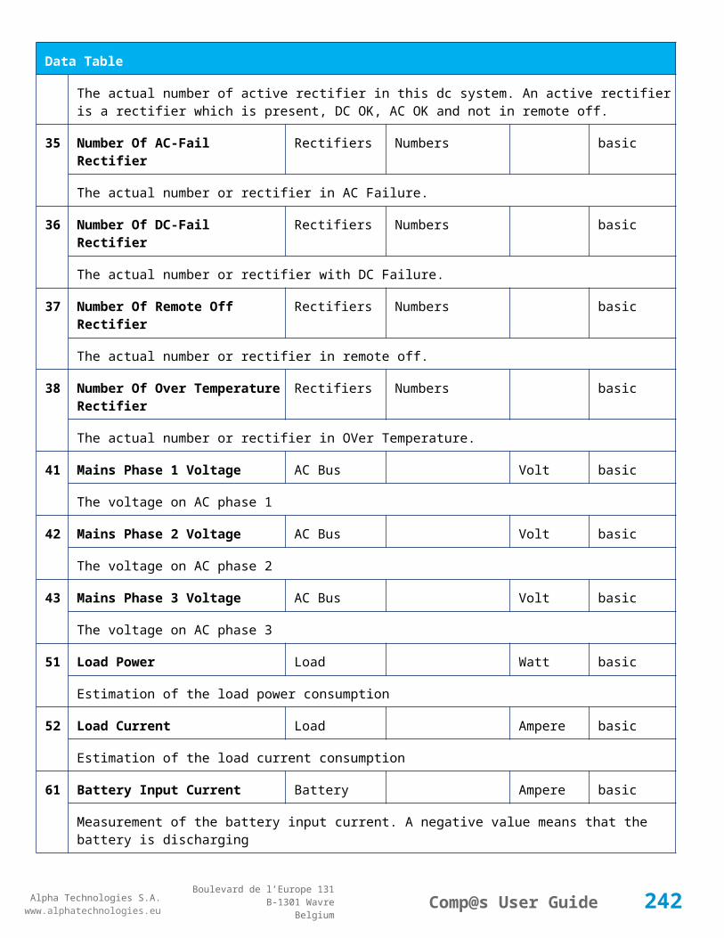
Alpha Technologies S.A.www.alphatechnologies.eu
Alpha Technologies S.A.www.alphatechnologies.eu
Comp@s User GuideBoulevard de l’Europe 131
B-1301 WavreBelgium
Config Table
The minimal discharging current to set the 'Battery On Discharge' alarm.
37 Current Hysteresis For Discharging Alarm
Battery Ampere 0/50 (0.2) basic
The hysteresis on the 'Battery On Discharge' alarm.
51 Boost Automatic Boost False/False (False) battery
The boost mode must be automatically after the fact that during a mains failure, the bus voltage went under the configured 'Boost Activation Low Voltage'. This allows charging the battery faster.
52 Boost Activation Low Voltage Boost Volt 43/50 (46) battery
The voltage under which the boost mode can be activated.
53 Boost Termination Voltage Boost Volt 50/58 (56.4) battery
The voltage over which the system must go back to floating mode.
54 Boost Termination Current Boost Ampere 0/100 (2) battery
The battery charging current under which the system must go back to floating mode.
55 Boost Termination Time Boost minute 10/240 (120) battery
The time in minute after which the system must go back in floating mode.
70 Battery Test End Voltage Battery Test Volt 30/60 (46) battery
The voltage at which any battery test must be stopped.
71 Battery Test Discharge Ratio Battery Test % 0/100 (0) battery
The ratio of the battery capacity to discharge. If 30 is set, 30% of the battery will be discharged during the test
72 Battery Test Interval Battery Test day 0/3000 (0) battery
The number of days between two automatically started battery test. If this parameter is set to 0, the battery test is not started automatically. The user can remotely or locally start or force this test.
73 Battery Test Discharge Current
Battery Test Ampere 0.5/100 (1000) battery
The current at which the battery must be discharged during a battery test. The monitoring regulates the bus voltage in order to satisfy this condition. The load current must be of course higher than this parameter.
74 Battery Test Minimal Discharge Current
Battery Test Ampere 0.2/90 (2) battery
The battery current under which the battery test must be stopped because the load is too low.
242

Alpha Technologies S.A.www.alphatechnologies.eu
Alpha Technologies S.A.www.alphatechnologies.eu
Comp@s User GuideBoulevard de l’Europe 131
B-1301 WavreBelgium
Config Table
75 Battery Test Time Out Battery Test minute 1/5000 (10) battery
The timeout in minute after which the battery test must be stopped.
76 Battery Test Requested Minutes Without Mains Failure
Battery Test minute 0/5000 (1440) battery
The minimal time in minute without mains failure in order to allow a battery start. This parameter is not taken into account when the battery test is forced.
83 Smart Energy Boolean Condition
Smart Energy 121-125 asset
This is the boolean condition which allows or not to automatically optimize the number of rectifier in remote off.
86 Battery LVD Node Id LVD True/False (False) basic
This is a list of the node id of the Smart Electronic LVDs, coma separated
91 Digital Input 1 Name Digital Inputs Distribution Breaker Open
basic
The name of the digital input 1
92 Digital Input 1 Normally Closed
Digital Inputs True/False (True) basic
True/False value defining if the digital input 1 is normally closed. If this digital input is not in this default state, the related alarm is set.
93 Digital Input 2 Name Digital Inputs Battery Breaker Open
basic
The name of the digital input 2
94 Digital Input 2 Normally Closed
Digital Inputs True/False (True) basic
True/False value defining if the digital input 2 is normally closed. If this digital input is not in this default state, the related alarm is set.
95 Digital Input 3 Name Digital Inputs Digital Input 3 basic
The name of the digital input 3
96 Digital Input 3 Normally Closed
Digital Inputs True/False (True) basic
True/False value defining if the digital input 3 is normally closed. If this digital input is not in this default state, the related alarm is set.
97 Digital Input 4 Name Digital Inputs Digital Input 4 basic
243
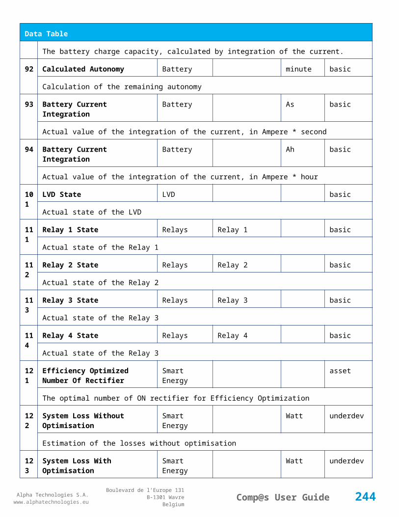
Alpha Technologies S.A.www.alphatechnologies.eu
Alpha Technologies S.A.www.alphatechnologies.eu
Comp@s User GuideBoulevard de l’Europe 131
B-1301 WavreBelgium
Config Table
The name of the digital input 4
98 Digital Input 4 Normally Closed
Digital Inputs True/False (True) basic
True/False value defining if the digital input 4 is normally closed. If this digital input is not in this default state, the related alarm is set.
99 Digital Input 5 Name Digital Inputs Digital Input 5 basic
The name of the digital input 5
100
Digital Input 5 Normally Closed
Digital Inputs True/False (True) basic
True/False value defining if the digital input 5 is normally closed. If this digital input is not in this default state, the related alarm is set.
101
Digital Input 6 Name Digital Inputs Digital Input 6 basic
The name of the digital input 6
102
Digital Input 6 Normally Closed
Digital Inputs True/False (True) basic
True/False value defining if the digital input 6 is normally closed. If this digital input is not in this default state, the related alarm is set.
111
Dry Alarm 1 Alternative Boolean Condition
Dry Alarms False plc
Another Boolean condition to activate the dry alarm relay 1. The way to define boolean condition is detailed in the PLC chapter.
112
Dry Alarm 2 Alternative Boolean Condition
Dry Alarms False plc
Another Boolean condition to activate the dry alarm relay 2. The way to define boolean condition is detailed in the PLC chapter.
113
Dry Alarm 3 Alternative Boolean Condition
Dry Alarms False plc
Another Boolean condition to activate the dry alarm relay 3. The way to define boolean condition is detailed in the PLC chapter.
114
Dry Alarm 4 Alternative Boolean Condition
Dry Alarms False plc
Another Boolean condition to activate the dry alarm relay 4. The way to define boolean condition is detailed in the PLC chapter.
13 Ambient Temperature Low Sensors degree C basic
244
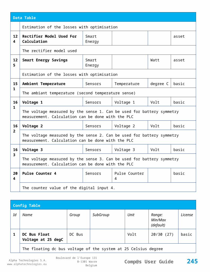
Alpha Technologies S.A.www.alphatechnologies.eu
Alpha Technologies S.A.www.alphatechnologies.eu
Comp@s User GuideBoulevard de l’Europe 131
B-1301 WavreBelgium
Config Table
1 The temperature under which the alarm 'Ambiant Temperature Too Low' must be set.
132
Ambient Temperature High Sensors degree C basic
The temperature under which the alarm 'Ambiant Temperature Too Low' must be set.
133
Ambient Temperature Hysteresis
Sensors degree C basic
The hysteresis on the 'Battery Temperature Too High' and 'Battery Temperature Too Low' alarms.
521
Read Access User Numbers Allowed Users (1,2,3,4,5) basic
The list of the user numbers which have read access to this equipment. The user numbers are coma separated. The accepted user id are 1,2,3,4 and 5. Ex: 1,3,4
522
Write Access User Numbers Allowed Users () basic
The list of the user numbers which have write access to this equipment. This means that these users can modify the configuration element, the alarm settings and use the control elements. The user numbers are coma separated. The accepted user ids are 1,2,3,4 and 5. Ex: 1,3,4
601
Event Table Length Event 10/4000 (100) basic
The maximum length of the table. The value must be comprised between 10 and 4000
611
SNMP Trap Targets IP Event 192.168.45.1 basic
One or multiple target IP to send traps, coma separated. Ex: 130.145.23.1, 130.23.12.45
612
Minimal Event Severity For Traps
Event (none) basic
This is the minimal severity of the event to send a SNMP trap
651
XML Events Primary Post URL
Event basic
This is the first URL at which the events related to this equipment must be posted. The XML ETSI standard is used in the posted data content.
652
XML Events Primary Post Login
Event basic
The login which must be used when posting events to the primary server
653
XML Events Primary Post Password
Event basic
The password which must be used when posting events to the primary server
661
XML Events Secondary Post URL
Event basic
245
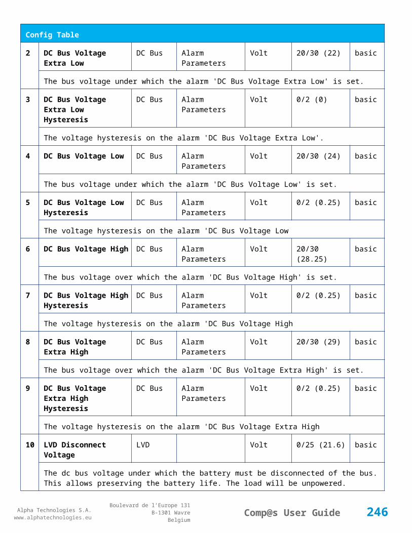
Alpha Technologies S.A.www.alphatechnologies.eu
Alpha Technologies S.A.www.alphatechnologies.eu
Comp@s User GuideBoulevard de l’Europe 131
B-1301 WavreBelgium
Config Table
This is the second URL at which the events related to this equipment must be posted. The XML ETSI standard is used in the posted data content. This allows having redundancy with the management server.
662
XML Events Secondary Post Login
Event basic
The login which must be used when posting events to the secondary server
663
XML Events Secondary Post Password
Event basic
The password which must be used when posting events to the secondary server
901
Number Of PLC Data PLC (0) plc
The number of PLC data. Every equipment can manage up to 20 user programmable data. Data elements are automatically added in the data table. Configuration parameters are added to set the PLC Data Name and the PLC Data Mathematical calculation. In order to use these functionalities, you need a license with the 'PLC' module
902
Number Of PLC Alarm PLC (0) plc
The number of PLC alarm. Every equipment can manage up to 20 user programmable alarms. Alarm elements are automatically added in the alarm table. The alarm parameters are added to set the PLC Alarm Name and the PLC Alarm Boolean condition. In order to use these functionalities, you need a licence with the 'PLC' module
Control Table
Id Name Group License
1 Back To Float DC Mode basic
The dc system must go back in floating mode.
2 Start Battery Test DC Mode battery
The dc system must start a battery test.
3 Force Battery Test DC Mode battery
The dc system must force a battery test.
4 Start Boost Mode DC Mode battery
The dc system must go in boost mode.
11 Open The LVD LVD basic
The LVD must be opened
246

Alpha Technologies S.A.www.alphatechnologies.eu
Alpha Technologies S.A.www.alphatechnologies.eu
Comp@s User GuideBoulevard de l’Europe 131
B-1301 WavreBelgium
Control Table
12 Close The LVD LVD basic
The LVD must be closed
21 Correct Battery Current Offset Battery basic
No information
31 Reset Battery Current Integration Battery basic
Reset the integration of the battery current.
41 Reset Last Battery Test State Battery battery
Reset the state of the last battery test. If an alarm 'Battery Last Test Failed' is set, the alarm will be cleared.
51 Save Configuration In MCU Save basic
Save configuration parameters in the MCU microcontroller. If comp@s is not present, the system will be correctly managed.
61 Set Digital Input 4 Counter Value Counters basic
Set Counter Value
501
Clear My Events Event basic
By writing '1' to this control element, all the events of this equipment will be cleared.
502
Clear All Events Event basic
By writing '1' to this control element, all the events of this equipment and all the events of all the sub-equipments will be cleared.
511
Add Event Event basic
This control element adds an event of severity none. The event name is the text written to this control element
512
Add Major Event Event basic
This control element adds an event of severity major. The event name is the text written to this control element
521
Reset Default Names Event basic
This control element adds an event of severity major. The event name is the text written to this control element
247

Alpha Technologies S.A.www.alphatechnologies.eu
Alpha Technologies S.A.www.alphatechnologies.eu
Comp@s User GuideBoulevard de l’Europe 131
B-1301 WavreBelgium
7.2.8 MCU0348M4 / MCU0348LP
Device Information
Name MCU0348M4 / MCU0348LP
Short Description
1U high controller with LCD display / Low profile controller (1/2U high)
Long Description
Monitoring and control unit, 1U high with LCD display, USB and Ethernet port - Captin300 line / Low profile monitoring and control unit for CAPTIN300 line
Hardware Reference
9413 060 10131 / 9413 060 10141
Software Reference
SOFT 000081 XX
Equipment Type
Monitoring Control Unit
ETSI Level /site/energy_system/dc_system
Description Table
Id Name Group SubGroup License
1 Description Description Custom Description basic
A free text zone to write a system description
2 Reference Description Custom Description basic
A free text zone to write the customer reference of the system
11 Product Name Description Product Info basic
The product name of the DC system monitoring
12 Hardware Reference Description Product Info basic
The hardware reference of the DC system monitoring
14 Software Reference Description Product Info asset
The serial number of the DC system monitoring
16 Serial Number Description Product Info asset
The serial number of the DC system monitoring
18 Manufacturing Date Description Product Info asset
The production date of the DC system monitoring
248
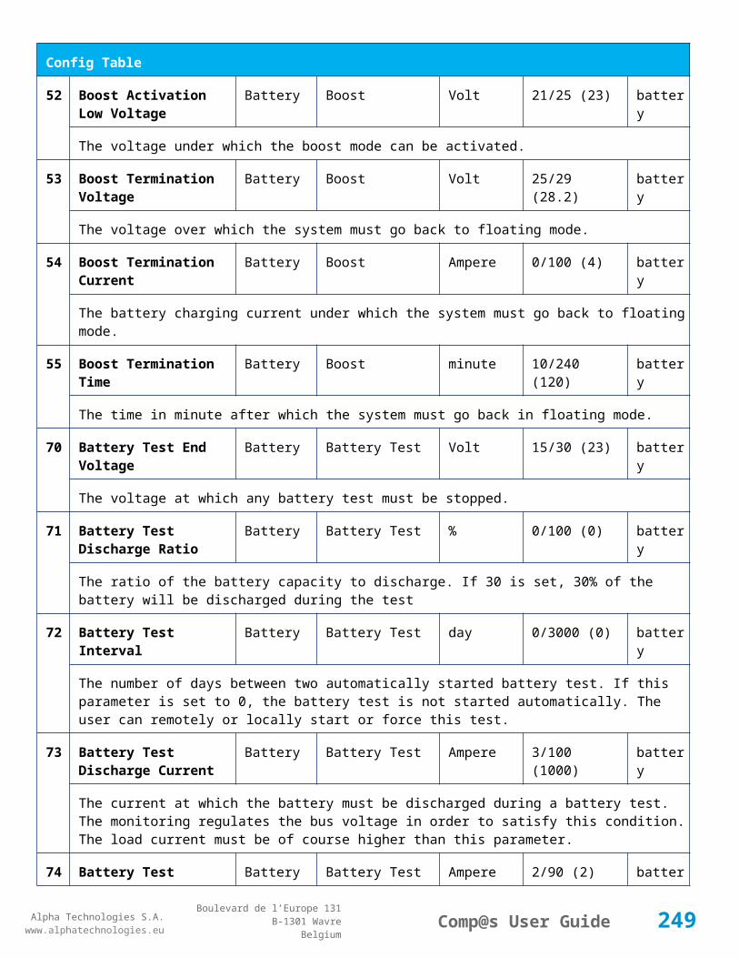
Alpha Technologies S.A.www.alphatechnologies.eu
Alpha Technologies S.A.www.alphatechnologies.eu
Comp@s User GuideBoulevard de l’Europe 131
B-1301 WavreBelgium
Alarm Table
Id Name Group SubGroup Severity Type (Level)
Set/Clear Delay
1 DC Bus Extra Low DC Bus major (6) 5 / 2
The bus voltage is extra low. The alarm is set when the bus voltage is lower than the configuration parameter 'DC Bus Voltage Extra Low'. There is an hysteresis on the alarm : 'DC Bus Voltage Extra Low Hysteresis'. The alarm is not activated when DC mode is BATTERY TEST
2 DC Bus Low DC Bus minor (4) 5 / 2
The bus voltage is low. The alarm is set when the bus voltage is lower than the configuration parameter 'DC Bus Voltage Low'. There is an hysteresis on the alarm : 'DC Bus Voltage Low Hysteresis'
3 DC Bus High DC Bus minor (4) 5 / 2
The bus voltage is high. The alarm is set when the bus voltage is higher than the configuration paramenter 'DC Bus Voltage High'. There is an hysterisis on the alarm : 'DC Bus Voltage High Hysteresis'
4 DC Bus Extra High DC Bus major (6) 5 / 2
The bus voltage is extra high. The alarm is set when the bus voltage is higher than the configuration paramenter 'DC Bus Voltage Extra High'. There is an hysterisis on the alarm : 'DC Bus Voltage Extra High Hysteresis'
5 DC Bus Voltage Sense Failure
DC Bus major (6) 5 / 2
The DC bus voltage sense is defective. The DC bus voltage is unconnected or unconfigured.
6 Mains Failure AC Bus minor (4) 5 / 2
The number of active rectifiers is equal to 0 and the number of rectifiers in AC failure is greater than 0.
7 Mains Partial Failure AC Bus minor (4) 10 / 2
The number of active rectifiers is greater than 0 and the number of rectifiers in AC failure is greater than 0. Some rectifiers are in AC Failure. It may be caused by an open breaker, a real phase failure, or by a rectifier failure.
8 Mains Low AC Bus warning (2) 10 / 2
The main voltage is low on one or more phases. No rectifier is in AC failure. If MCU master type is 30110, 3096 or 3048M6, an hysteresis _phase123Hysteresis is added to the voltage lower limit
10
One Rectifier Failure Rectifiers minor (4) 5 / 2
One rectifier must be replaced or is not powered correctly. The DC fail alarm of the rectifier is set. The number of rectifier with DC Failure is higher than 0, there is no mains failure, and the 'More Than One Rectifier Failure alarm is not set.'
249
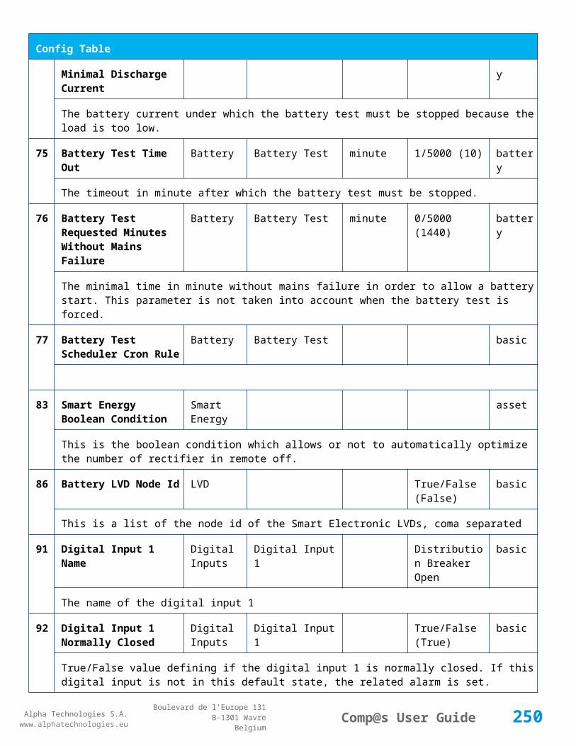
Alpha Technologies S.A.www.alphatechnologies.eu
Alpha Technologies S.A.www.alphatechnologies.eu
Comp@s User GuideBoulevard de l’Europe 131
B-1301 WavreBelgium
Alarm Table
11
More Than One Rectifier Failure
Rectifiers major (6) 10 / 2
There is no mains failure and number of rectifier failures is greater than 1.
12
Missing Rectifiers Rectifiers major (6) 5 / 2
There is not enough rectifier according to the configuration parameter : 'Minimal Number Of Rectifier'
13
Battery Last Test Failed Battery Battery Test minor (3) 5 / 2
The last battery test did not succeed and was not cancelled. Maybe the battery should be replaced.
14
Battery On Discharge Battery minor (4) 10 / 2
The battery is discharging. This means that the load is too high for the installed rectifiers. This alarm is inactive when the system in AC Failure or during a battery test. There is an hysteresis corresponding to battery parameter 'Is discharging current hysteresis'.
17
Battery LVD Relay Open LVD major (6) 5 / 2
The battery Low Voltage Disconnector is open. On Systems without LVD_Status signal, like MCU 1848 or MCU 1x6, the alarm is present only if the signal LVD_COM asks to open the LVD
18
Battery Temperature Too High
Battery Temperature minor (3) 5 / 2
The temperature of the battery is too high and is greater than -600 units. There is an hysteresis corresponding to battery parameter 'Temperature hysteresis'.
19
Battery Temperature Too Low
Battery Temperature minor (3) 5 / 2
The temperature of the battery is too low and is greater than -600 units. There is an hysteresis corresponding to battery parameter 'Temperature hysteresis'.
20
Battery Temperature Sensor Fail
Battery Temperature minor (3) 5 / 2
The battery temperature sensor (NTC) value is inferior to -500 units meaning that it is not connected or defective.
21
Ambient Temperature Too High
Sensors Temperature minor (0) 5 / 2
The ambient temperature is too high and is greater than -600 units. There is an hysteresis corresponding to parameter 'Ambiant temperature hysteresis'. This alarm is only activated on MCU master types 30110, 3096, 30125, 0024, 0948, 0548, 0348, 0948 and 3048M6.
22
Ambient Temperature Too Low
Sensors Temperature minor (0) 5 / 2
The ambient temperature is too low and is greater than -600 units. There is an hysteresis corresponding to parameter 'Ambiant temperature hysteresis'. This alarm is only activated on MCU master types
250

Alpha Technologies S.A.www.alphatechnologies.eu
Alpha Technologies S.A.www.alphatechnologies.eu
Comp@s User GuideBoulevard de l’Europe 131
B-1301 WavreBelgium
Alarm Table
30110, 3096, 30125, 0024, 0948, 0548, 0348, 0948 and 3048M6.
23
Ambient Temperature Sensor Fail
Sensors Temperature minor (0) 5 / 2
The ambiant temperature sensor (NTC) value is inferior to -500 units meaning that it is not connected or defective.
25
Distribution Breaker Open Digital Inputs major (6) 5 / 2
This alarm is related to digital input 1. This alarm is activated if digital input value is different to configuration parameter 'Digital Input Alarm Value'
26
Battery Breaker Open Digital Inputs minor (4) 5 / 2
This alarm is related to digital input 2. This alarm is activated if digital input value is different to configuration parameter 'Digital Input Alarm Value'
27
Digital Input 3 Digital Inputs none (0) 5 / 2
This alarm is related to digital input 3. This alarm is activated if digital input value is different to configuration parameter 'Digital Input Alarm Value'
28
Digital Input 4 Digital Inputs none (0) 5 / 2
This alarm is related to digital input 4. This alarm is activated if digital input value is different to configuration parameter 'Digital Input Alarm Value'
29
Digital Input 5 Digital Inputs none (0) 5 / 2
This alarm is related to digital input 5. This alarm is activated if digital input value is different to configuration parameter 'Digital Input Alarm Value'
30
Digital Input 6 Digital Inputs none (0) 5 / 2
This alarm is related to digital input 6. This alarm is activated if digital input value is different to configuration parameter 'Digital Input Alarm Value'
Data Table
Id Name Group SubGroup Unit License
1 DC Mode System basic
The DC system can have 4 values: 'FLOAT', 'BOOST', 'BATTERY_TEST', 'AC_FAILURE' or SAFE
2 Previous DC Mode System basic
The previous value of the DC Mode
11 Bus Voltage DC Bus Volt basic
251

Alpha Technologies S.A.www.alphatechnologies.eu
Alpha Technologies S.A.www.alphatechnologies.eu
Comp@s User GuideBoulevard de l’Europe 131
B-1301 WavreBelgium
Data Table
The DC bus voltage in volt.
12 Ratio Delivered On Available Power
System % basic
This is the ratio of the delivered power divided by the installed power, in %.
13 Minutes Since Last AC Failure Begin
AC Bus minute basic
The number of minute since the last AC Failure begin
14 Minutes Since Last AC Failure End
AC Bus minute basic
The number of minute since the last AC Failure end
21 Rectifiers Output Power Rectifiers Watt basic
The sum of the delivered rectifier power
22 Rectifiers Output Current Rectifiers Ampere basic
The sum of the delivered rectifier current
23 Rectifiers Output Power Max Rectifiers Watt basic
The sum of the deliverable rectifier power
24 Rectifiers Output Current Max Rectifiers Ampere basic
The sum of the deliverable rectifier current
31 Number Of Rectifier Max Rectifiers Numbers basic
The maximum possible number of rectifier in this dc system
32 Number Of Present Rectifier Rectifiers Numbers basic
The actual number of present rectifier in this dc system
33 Number Of Absent Rectifier Rectifiers Numbers basic
The actual number of absent rectifier in this dc system
34 Number Of Active Rectifier Rectifiers Numbers basic
The actual number of active rectifier in this dc system. An active rectifier is a rectifier which is present, DC OK, AC OK and not in remote off.
35 Number Of AC-Fail Rectifier Rectifiers Numbers basic
The actual number or rectifier in AC Failure.
252

Alpha Technologies S.A.www.alphatechnologies.eu
Alpha Technologies S.A.www.alphatechnologies.eu
Comp@s User GuideBoulevard de l’Europe 131
B-1301 WavreBelgium
Data Table
36 Number Of DC-Fail Rectifier Rectifiers Numbers basic
The actual number or rectifier with DC Failure.
37 Number Of Remote Off Rectifier Rectifiers Numbers basic
The actual number or rectifier in remote off.
38 Number Of Over Temperature Rectifier
Rectifiers Numbers basic
The actual number or rectifier in OVer Temperature.
51 Load Power Load Watt basic
Estimation of the load power consumption
52 Load Current Load Ampere basic
Estimation of the load current consumption
61 Battery Input Current Battery Ampere basic
Measurement of the battery input current. A negative value means that the battery is discharging
62 Battery Input Power Battery Watt basic
Measurement of the battery input power. A negative value means that the battery is discharging
71 Battery Temperature Battery Temperature degree C basic
The battery temperature
72 Battery Test State Battery Battery Test basic
This is about the result of the last battery test. 9 values are possible : NEVER_TESTED, SUCCESS, ON_GOING, FAILED_TIMEOUT, FAILED_VBUS_TOO_LOW, FAILED_LOAD_TOO_LOW, FAILED_AC_FAILURE, FAILED_CANCELED, FAILED_LVD_OPENED
73 Battery Test Discharged Capacity Ratio
Battery Battery Test % basic
This is the battery capacity, in percent, discharged during the last battery test. This value is updated at the end of the battery test.
74 Battery Test Discharged Capacity
Battery Battery Test Ah basic
This is the battery capacity, in ampere hour, discharged during the last battery test. This value is updated at the end of the battery test.
75 Battery Test Final Voltage Battery Battery Test % basic
This is the bus voltage at the end of the last battery test. This value is updated at the end of the battery
253

Alpha Technologies S.A.www.alphatechnologies.eu
Alpha Technologies S.A.www.alphatechnologies.eu
Comp@s User GuideBoulevard de l’Europe 131
B-1301 WavreBelgium
Data Table
test.
81 Previous Battery Test State Battery Battery Test basic
The result of the previous battery test
82 Minutes Since Last Test Battery Battery Battery Test basic
The number of minute without battery test
84 Next Scheduled Battery Test Battery Battery Test basic
The date and time of the next time the scheduled battery test will run
91 Battery Charge Capacity Battery % basic
The battery charge capacity, calculated by integration of the current.
92 Calculated Autonomy Battery minute basic
Calculation of the remaining autonomy
93 Battery Current Integration Battery As basic
Actual value of the integration of the current, in Ampere * second
94 Battery Current Integration Battery Ah basic
Actual value of the integration of the current, in Ampere * hour
101
LVD State LVD basic
Actual state of the LVD
111
Relay 1 State Relays Relay 1 basic
Actual state of the Relay 1
112
Relay 2 State Relays Relay 2 basic
Actual state of the Relay 2
113
Relay 3 State Relays Relay 3 basic
Actual state of the Relay 3
114
Relay 4 State Relays Relay 4 basic
Actual state of the Relay 3
121
Efficiency Optimized Number Of Rectifier
Smart Energy asset
The optimal number of ON rectifier for Efficiency Optimization
254

Alpha Technologies S.A.www.alphatechnologies.eu
Alpha Technologies S.A.www.alphatechnologies.eu
Comp@s User GuideBoulevard de l’Europe 131
B-1301 WavreBelgium
Data Table
122
System Loss Without Optimisation
Smart Energy Watt underdev
Estimation of the losses without optimisation
123
System Loss With Optimisation Smart Energy Watt underdev
Estimation of the losses with optimisation
124
Rectifier Model Used For Calculation
Smart Energy asset
The rectifier model used
125
Smart Energy Savings Smart Energy Watt asset
Estimation of the losses with optimisation
151
Ambient Temperature Sensors Temperature degree C basic
The ambiant temperature (second temperature sense)
204
Pulse Counter 4 Sensors Pulse Counter 4 basic
The counter value of the digital input 4.
Config Table
Id Name Group SubGroup Unit Range: Min/Max (default)
License
1 DC Bus Float Voltage at 25 degC
DC Bus Volt 40/60 (54) basic
The floating dc bus voltage of the system at 25 Celsius degree
2 DC Bus Voltage Extra Low
DC Bus Alarm Parameters Volt 40/60 (45) basic
The bus voltage under which the alarm 'DC Bus Voltage Extra Low' is set.
3 DC Bus Voltage Extra Low Hysteresis
DC Bus Alarm Parameters Volt 0/5 (1) basic
The voltage hysteresis on the alarm 'DC Bus Voltage Extra Low'.
4 DC Bus Voltage Low DC Bus Alarm Parameters Volt 40/60 (48) basic
The bus voltage under which the alarm 'DC Bus Voltage Low' is set.
5 DC Bus Voltage Low DC Bus Alarm Parameters Volt 0/5 (0.5) basic
255

Alpha Technologies S.A.www.alphatechnologies.eu
Alpha Technologies S.A.www.alphatechnologies.eu
Comp@s User GuideBoulevard de l’Europe 131
B-1301 WavreBelgium
Config Table
Hysteresis
The voltage hysteresis on the alarm 'DC Bus Voltage Low
6 DC Bus Voltage High DC Bus Alarm Parameters Volt 40/60 (56.5) basic
The bus voltage over which the alarm 'DC Bus Voltage High' is set.
7 DC Bus Voltage High Hysteresis
DC Bus Alarm Parameters Volt 0/5 (0.5) basic
The voltage hysteresis on the alarm 'DC Bus Voltage High
8 DC Bus Voltage Extra High
DC Bus Alarm Parameters Volt 40/60 (58) basic
The bus voltage over which the alarm 'DC Bus Voltage Extra High' is set.
9 DC Bus Voltage Extra High Hysteresis
DC Bus Alarm Parameters Volt 0/5 (0.5) basic
The voltage hysteresis on the alarm 'DC Bus Voltage Extra High
10 LVD Disconnect Voltage LVD Volt 0/50 (43.2) basic
The dc bus voltage under which the battery must be disconnected of the bus. This allows preserving the battery life. The load will be unpowered.
11 LVD Disconnect Delay LVD second 1/2000 (1) basic
The delay in second before disconnecting the battery if the dc bus voltage is under the configured disconnected voltage. This avoids disconnection during a low bus transient.
21 Temperature Compensation Slope
Battery Temperature Compensation
mV/degree -1000/0 (-72) basic
The slope of the battery temperature compensation in mv/degree. For a 48V system, -72mV/degree is often used.
22 Maximum Positive Temperature Compensation
Battery Temperature Compensation
Volt 0/10 (3) basic
The maximal allowed positive compensation.
23 Maximum Negative Temperature Compensation
Battery Temperature Compensation
Volt -10/0 (-3) basic
The maximal allowed negative compensation.
25 Minimal Number Of Present Rectifiers
Rectifiers Alarm Parameters 0/100 (0) basic
256

Alpha Technologies S.A.www.alphatechnologies.eu
Alpha Technologies S.A.www.alphatechnologies.eu
Comp@s User GuideBoulevard de l’Europe 131
B-1301 WavreBelgium
Config Table
The minimal number of rectifier which must be present. If there is less present rectifiers, the alarm 'Missing Rectifiers' is set.
26 Rectifier Model Rectifiers basic
The rectifier model
27 Forced Remote Off Rectifers
Rectifiers basic
A list of rectifier which are forced in remote off. The id of the rectifier must be coma separated. Ex: 1,3 will maintain rectifier 1 and 3 off.
31 Battery Charge Current Limit
Battery Battery Charge Parameters
Ampere 0.5/1000 (1000) basic
The maximal battery current when the battery is charging. The monitoring regulates the bus voltage in order to satisfy this condition. This parameter is often equal to the nominal battery capacity divided by 10.
32 Battery String Capacity Battery Ah 3/1000 (100) basic
The battery capacity in Ah.
33 Battery Temperature Low
Battery Alarm Parameters degree C -100/20 (0) basic
The temperature under which the alarm 'Battery Temperature Too Low' must be set.
34 Battery Temperature High
Battery Alarm Parameters degree C 5/100 (40) basic
The temperature over which the alarm 'Battery Temperature Too High' must be set.
35 Battery Temperature Hysteresis
Battery Alarm Parameters degree C 0/10 (2) basic
The hysteresis on the 'Battery Temperature Too High' and 'Battery Temperature Too Low' alarms.
36 Minimal Current For Discharging Alarm
Battery Alarm Parameters Ampere 0/1000 (0.5) basic
The minimal discharging current to set the 'Battery On Discharge' alarm.
37 Current Hysteresis For Discharging Alarm
Battery Alarm Parameters Ampere 0/50 (0.2) basic
The hysteresis on the 'Battery On Discharge' alarm.
51 Boost Automatic Battery Boost False/False (False)
battery
The boost mode must be automatically after the fact that during a mains failure, the bus voltage went under the configured 'Boost Activation Low Voltage'. This allows charging the battery faster.
257

Alpha Technologies S.A.www.alphatechnologies.eu
Alpha Technologies S.A.www.alphatechnologies.eu
Comp@s User GuideBoulevard de l’Europe 131
B-1301 WavreBelgium
Config Table
52 Boost Activation Low Voltage
Battery Boost Volt 43/50 (46) battery
The voltage under which the boost mode can be activated.
53 Boost Termination Voltage
Battery Boost Volt 50/58 (56.4) battery
The voltage over which the system must go back to floating mode.
54 Boost Termination Current
Battery Boost Ampere 0/100 (2) battery
The battery charging current under which the system must go back to floating mode.
55 Boost Termination Time Battery Boost minute 10/240 (120) battery
The time in minute after which the system must go back in floating mode.
70 Battery Test End Voltage
Battery Battery Test Volt 30/60 (46) battery
The voltage at which any battery test must be stopped.
71 Battery Test Discharge Ratio
Battery Battery Test % 0/100 (0) battery
The ratio of the battery capacity to discharge. If 30 is set, 30% of the battery will be discharged during the test
72 Battery Test Interval Battery Battery Test day 0/3000 (0) battery
The number of days between two automatically started battery test. If this parameter is set to 0, the battery test is not started automatically. The user can remotely or locally start or force this test.
73 Battery Test Discharge Current
Battery Battery Test Ampere 0.5/100 (1000) battery
The current at which the battery must be discharged during a battery test. The monitoring regulates the bus voltage in order to satisfy this condition. The load current must be of course higher than this parameter.
74 Battery Test Minimal Discharge Current
Battery Battery Test Ampere 0.2/90 (2) battery
The battery current under which the battery test must be stopped because the load is too low.
75 Battery Test Time Out Battery Battery Test minute 1/5000 (10) battery
The timeout in minute after which the battery test must be stopped.
76 Battery Test Requested Minutes Without Mains Failure
Battery Battery Test minute 0/5000 (1440) battery
258

Alpha Technologies S.A.www.alphatechnologies.eu
Alpha Technologies S.A.www.alphatechnologies.eu
Comp@s User GuideBoulevard de l’Europe 131
B-1301 WavreBelgium
Config Table
The minimal time in minute without mains failure in order to allow a battery start. This parameter is not taken into account when the battery test is forced.
77 Battery Test Scheduler Cron Rule
Battery Battery Test basic
83 Smart Energy Boolean Condition
Smart Energy
asset
This is the boolean condition which allows or not to automatically optimize the number of rectifier in remote off.
86 Battery LVD Node Id LVD True/False (False)
basic
This is a list of the node id of the Smart Electronic LVDs, coma separated
91 Digital Input 1 Name Digital Inputs
Digital Input 1 Distribution Breaker Open
basic
The name of the digital input 1
92 Digital Input 1 Normally Closed
Digital Inputs
Digital Input 1 True/False (True)
basic
True/False value defining if the digital input 1 is normally closed. If this digital input is not in this default state, the related alarm is set.
93 Digital Input 2 Name Digital Inputs
Digital Input 2 Battery Breaker Open
basic
The name of the digital input 2
94 Digital Input 2 Normally Closed
Digital Inputs
Digital Input 2 True/False (True)
basic
True/False value defining if the digital input 2 is normally closed. If this digital input is not in this default state, the related alarm is set.
95 Digital Input 3 Name Digital Inputs
Digital Input 3 Digital Input 3 basic
The name of the digital input 3
96 Digital Input 3 Normally Closed
Digital Inputs
Digital Input 3 True/False (True)
basic
True/False value defining if the digital input 3 is normally closed. If this digital input is not in this default state, the related alarm is set.
97 Digital Input 4 Name Digital Inputs
Digital Input 4 Digital Input 4 basic
259

Alpha Technologies S.A.www.alphatechnologies.eu
Alpha Technologies S.A.www.alphatechnologies.eu
Comp@s User GuideBoulevard de l’Europe 131
B-1301 WavreBelgium
Config Table
The name of the digital input 4
98 Digital Input 4 Normally Closed
Digital Inputs
Digital Input 4 True/False (True)
basic
True/False value defining if the digital input 4 is normally closed. If this digital input is not in this default state, the related alarm is set.
99 Digital Input 5 Name Digital Inputs
Digital Input 5 Digital Input 5 basic
The name of the digital input 5
100
Digital Input 5 Normally Closed
Digital Inputs
Digital Input 5 True/False (True)
basic
True/False value defining if the digital input 5 is normally closed. If this digital input is not in this default state, the related alarm is set.
101
Digital Input 6 Name Digital Inputs
Digital Input 6 Digital Input 6 basic
The name of the digital input 6
102
Digital Input 6 Normally Closed
Digital Inputs
Digital Input 6 True/False (True)
basic
True/False value defining if the digital input 6 is normally closed. If this digital input is not in this default state, the related alarm is set.
111
Dry Alarm 1 Alternative Boolean Condition
Relays Relay 1 plc
Another Boolean condition to activate the dry alarm relay 1. The way to define boolean condition is detailed in the PLC chapter.
112
Dry Alarm 2 Alternative Boolean Condition
Relays Relay 2 plc
Another Boolean condition to activate the dry alarm relay 2. The way to define boolean condition is detailed in the PLC chapter.
113
Dry Alarm 3 Alternative Boolean Condition
Relays Relay 3 plc
Another Boolean condition to activate the dry alarm relay 3. The way to define boolean condition is detailed in the PLC chapter.
114
Dry Alarm 4 Alternative Boolean Condition
Relays Relay 4 plc
Another Boolean condition to activate the dry alarm relay 4. The way to define boolean condition is detailed in the PLC chapter.
260

Alpha Technologies S.A.www.alphatechnologies.eu
Alpha Technologies S.A.www.alphatechnologies.eu
Comp@s User GuideBoulevard de l’Europe 131
B-1301 WavreBelgium
Config Table
131
Ambient Temperature Low
Sensors Temperature degree C basic
The temperature under which the alarm 'Ambiant Temperature Too Low' must be set.
132
Ambient Temperature High
Sensors Temperature degree C basic
The temperature under which the alarm 'Ambiant Temperature Too Low' must be set.
133
Ambient Temperature Hysteresis
Sensors Temperature degree C basic
The hysteresis on the 'Battery Temperature Too High' and 'Battery Temperature Too Low' alarms.
521
Read Access User Numbers
Generic Allowed Users (1,2,3,4,5) basic
The list of the user numbers which have read access to this equipment. The user numbers are coma separated. The accepted user id are 1,2,3,4 and 5. Ex: 1,3,4
522
Write Access User Numbers
Generic Allowed Users () basic
The list of the user numbers which have write access to this equipment. This means that these users can modify the configuration element, the alarm settings and use the control elements. The user numbers are coma separated. The accepted user ids are 1,2,3,4 and 5. Ex: 1,3,4
601
Event Table Length Generic Events 10/4000 (100) basic
The maximum length of the table. The value must be comprised between 10 and 4000
602
Event Table Length By Rectifier
Generic Events 10/4000 (100) basic
The maximum length of the table. The value must be comprised between 10 and 4000
901
Number Of PLC Data PLC (0) plc
The number of PLC data. Every equipment can manage up to 20 user programmable data. Data elements are automatically added in the data table. Configuration parameters are added to set the PLC Data Name and the PLC Data Mathematical calculation. In order to use these functionalities, you need a license with the 'PLC' module
902
Number Of PLC Alarm PLC (0) plc
The number of PLC alarm. Every equipment can manage up to 20 user programmable alarms. Alarm elements are automatically added in the alarm table. The alarm parameters are added to set the PLC Alarm Name and the PLC Alarm Boolean condition. In order to use these functionalities, you need a licence with the 'PLC' module
261

Alpha Technologies S.A.www.alphatechnologies.eu
Alpha Technologies S.A.www.alphatechnologies.eu
Comp@s User GuideBoulevard de l’Europe 131
B-1301 WavreBelgium
Control Table
Id Name Group SubGroup License
1 Back To Float System basic
The dc system must go back in floating mode.
2 Start Battery Test System battery
The dc system must start a battery test.
3 Force Battery Test System battery
The dc system must force a battery test.
4 Start Boost Mode System battery
The dc system must go in boost mode.
11 Open The LVD LVD basic
Try to open the LVD. It could not work if the LVD is electronic, and the request will be canceled after 15 sec.
12 Close The LVD LVD basic
The LVD must be closed
21 Correct Battery Current Offset Battery basic
31 Reset Battery Current Integration Battery basic
Reset the integration of the battery current.
41 Reset Last Battery Test State Battery battery
Reset the state of the last battery test. If an alarm 'Battery Last Test Failed' is set, the alarm will be cleared.
51 Save Configuration In MCU Save basic
Save configuration parameters in the MCU microcontroller. If comp@s is not present, the system will be correctly managed.
55 Set MCU Specific Configuration Id Advanced Factory basic
This control allows to reconfigure the MCU to support specific hardware configuration, with embedded distribution for example
61 Set Digital Input 4 Counter Value Digital Inputs Digital Input 4 basic
Set Counter Value
262
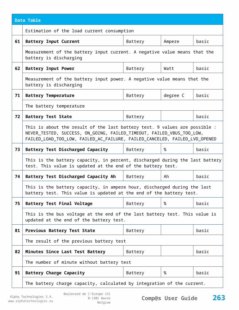
Alpha Technologies S.A.www.alphatechnologies.eu
Alpha Technologies S.A.www.alphatechnologies.eu
Comp@s User GuideBoulevard de l’Europe 131
B-1301 WavreBelgium
Control Table
111
Invert Relay 1 State For X Seconds Relays Relay 1 basic
Generate Pulse on relay 1
112
Invert Relay 2 State For X Seconds Relays Relay 2 basic
Generate Pulse on relay 2
113
Invert Relay 3 State For X Seconds Relays Relay 3 basic
Generate Pulse on relay 3
114
Invert Relay 4 State For X Seconds Relays Relay 4 basic
Generate Pulse on relay 4
501
Clear My Events Generic Events basic
By writing '1' to this control element, all the events of this equipment will be cleared.
502
Clear All Events Generic Events basic
By writing '1' to this control element, all the events of this equipment and all the events of all the sub-equipments will be cleared.
511
Add Event Generic Events basic
This control element adds an event of severity none. The event name is the text written to this control element
512
Add Major Event Generic Events basic
This control element adds an event of severity major. The event name is the text written to this control element
521
Reset Default Names And Groups Generic Renaming basic
This control element resets all the element Names, Groups and Subgroups to default values for this equipment
522
Reset Default Names And Groups Recursive Generic Renaming basic
This control element resets all the element Names, Groups and Subgroups to default values for this equipment and all sub equipments
7.2.9 MCU0548M4
Device Information
Name MCU0548M4
Short Description Controller with basic site monitoring functions (4x500W)
263

Alpha Technologies S.A.www.alphatechnologies.eu
Alpha Technologies S.A.www.alphatechnologies.eu
Comp@s User GuideBoulevard de l’Europe 131
B-1301 WavreBelgium
Device Information
Long Description Monitoring and control unit with front connector for site monitoring - ACE054 line
Hardware Reference 9413 060 55101
Software Reference SOFT 000080 XX
Equipment Type Monitoring Control Unit
ETSI Level /site/energy_system/dc_system
Description Table
Id Name Group SubGroup License
1 Description Description Custom Description basic
A free text zone to write a system description
2 Reference Description Custom Description basic
A free text zone to write the customer reference of the system
11 Product Name Description Product Info basic
The product name of the DC system monitoring
12 Hardware Reference Description Product Info basic
The hardware reference of the DC system monitoring
14 Software Reference Description Product Info asset
The serial number of the DC system monitoring
16 Serial Number Description Product Info asset
The serial number of the DC system monitoring
18 Manufacturing Date Description Product Info asset
The production date of the DC system monitoring
Alarm Table
Id Name Group SubGroup Severity Type (Level)
Set/Clear Delay
1 DC Bus Extra Low DC Bus major (6) 5 / 2
The bus voltage is extra low. The alarm is set when the bus voltage is lower than the configuration parameter 'DC Bus Voltage Extra Low'. There is an hysteresis on the alarm : 'DC Bus Voltage Extra Low
264

Alpha Technologies S.A.www.alphatechnologies.eu
Alpha Technologies S.A.www.alphatechnologies.eu
Comp@s User GuideBoulevard de l’Europe 131
B-1301 WavreBelgium
Alarm Table
Hysteresis'. The alarm is not activated when DC mode is BATTERY TEST
2 DC Bus Low DC Bus minor (4) 5 / 2
The bus voltage is low. The alarm is set when the bus voltage is lower than the configuration parameter 'DC Bus Voltage Low'. There is an hysteresis on the alarm : 'DC Bus Voltage Low Hysteresis'
3 DC Bus High DC Bus minor (4) 5 / 2
The bus voltage is high. The alarm is set when the bus voltage is higher than the configuration paramenter 'DC Bus Voltage High'. There is an hysterisis on the alarm : 'DC Bus Voltage High Hysteresis'
4 DC Bus Extra High DC Bus major (6) 5 / 2
The bus voltage is extra high. The alarm is set when the bus voltage is higher than the configuration paramenter 'DC Bus Voltage Extra High'. There is an hysterisis on the alarm : 'DC Bus Voltage Extra High Hysteresis'
5 DC Bus Voltage Sense Failure
DC Bus major (6) 5 / 2
The DC bus voltage sense is defective. The DC bus voltage is unconnected or unconfigured.
6 Mains Failure AC Bus minor (4) 5 / 2
The number of active rectifiers is equal to 0 and the number of rectifiers in AC failure is greater than 0.
7 Mains Partial Failure AC Bus minor (4) 10 / 2
The number of active rectifiers is greater than 0 and the number of rectifiers in AC failure is greater than 0. Some rectifiers are in AC Failure. It may be caused by an open breaker, a real phase failure, or by a rectifier failure.
8 Mains Low AC Bus warning (2) 10 / 2
The main voltage is low on one or more phases. No rectifier is in AC failure. If MCU master type is 30110, 3096 or 3048M6, an hysteresis _phase123Hysteresis is added to the voltage lower limit
10
One Rectifier Failure Rectifiers minor (4) 5 / 2
One rectifier must be replaced or is not powered correctly. The DC fail alarm of the rectifier is set. The number of rectifier with DC Failure is higher than 0, there is no mains failure, and the 'More Than One Rectifier Failure alarm is not set.'
11
More Than One Rectifier Failure
Rectifiers major (6) 10 / 2
There is no mains failure and number of rectifier failures is greater than 1.
12
Missing Rectifiers Rectifiers major (6) 5 / 2
There is not enough rectifier according to the configuration parameter : 'Minimal Number Of Rectifier'
265

Alpha Technologies S.A.www.alphatechnologies.eu
Alpha Technologies S.A.www.alphatechnologies.eu
Comp@s User GuideBoulevard de l’Europe 131
B-1301 WavreBelgium
Alarm Table
13
Battery Last Test Failed Battery Battery Test minor (3) 5 / 2
The last battery test did not succeed and was not cancelled. Maybe the battery should be replaced.
14
Battery On Discharge Battery minor (4) 10 / 2
The battery is discharging. This means that the load is too high for the installed rectifiers. This alarm is inactive when the system in AC Failure or during a battery test. There is an hysteresis corresponding to battery parameter 'Is discharging current hysteresis'.
17
Battery LVD Relay Open LVD major (6) 5 / 2
The battery Low Voltage Disconnector is open. On Systems without LVD_Status signal, like MCU 1848 or MCU 1x6, the alarm is present only if the signal LVD_COM asks to open the LVD
18
Battery Temperature Too High
Battery Temperature minor (3) 5 / 2
The temperature of the battery is too high and is greater than -600 units. There is an hysteresis corresponding to battery parameter 'Temperature hysteresis'.
19
Battery Temperature Too Low
Battery Temperature minor (3) 5 / 2
The temperature of the battery is too low and is greater than -600 units. There is an hysteresis corresponding to battery parameter 'Temperature hysteresis'.
20
Battery Temperature Sensor Fail
Battery Temperature minor (3) 5 / 2
The battery temperature sensor (NTC) value is inferior to -500 units meaning that it is not connected or defective.
21
Ambient Temperature Too High
Sensors Temperature minor (0) 5 / 2
The ambient temperature is too high and is greater than -600 units. There is an hysteresis corresponding to parameter 'Ambiant temperature hysteresis'. This alarm is only activated on MCU master types 30110, 3096, 30125, 0024, 0948, 0548, 0348, 0948 and 3048M6.
22
Ambient Temperature Too Low
Sensors Temperature minor (0) 5 / 2
The ambient temperature is too low and is greater than -600 units. There is an hysteresis corresponding to parameter 'Ambiant temperature hysteresis'. This alarm is only activated on MCU master types 30110, 3096, 30125, 0024, 0948, 0548, 0348, 0948 and 3048M6.
23
Ambient Temperature Sensor Fail
Sensors Temperature minor (0) 5 / 2
The ambiant temperature sensor (NTC) value is inferior to -500 units meaning that it is not connected or defective.
2 Humidity Out Of Range Sensors Humidity major (0) 5 / 2
266

Alpha Technologies S.A.www.alphatechnologies.eu
Alpha Technologies S.A.www.alphatechnologies.eu
Comp@s User GuideBoulevard de l’Europe 131
B-1301 WavreBelgium
Alarm Table
4 The humidity is not comprised between a lower limit, corresponding to configuration parameter 'Humidity Low', and a upper limit, corresponding to configuration parameter 'Humidity High'. There is an hysteresis corresponding to configuration parameter 'Humidity Hysteresis'. This alarm is only active in MCU master types 0548.
25
Distribution Breaker Open Digital Inputs major (6) 5 / 2
This alarm is related to digital input 1. This alarm is activated if digital input value is different to configuration parameter 'Digital Input Alarm Value'
26
Battery Breaker Open Digital Inputs minor (4) 5 / 2
This alarm is related to digital input 2. This alarm is activated if digital input value is different to configuration parameter 'Digital Input Alarm Value'
27
Digital Input 3 Digital Inputs none (0) 5 / 2
This alarm is related to digital input 3. This alarm is activated if digital input value is different to configuration parameter 'Digital Input Alarm Value'
28
Digital Input 4 Digital Inputs none (0) 5 / 2
This alarm is related to digital input 4. This alarm is activated if digital input value is different to configuration parameter 'Digital Input Alarm Value'
29
Digital Input 5 Digital Inputs none (0) 5 / 2
This alarm is related to digital input 5. This alarm is activated if digital input value is different to configuration parameter 'Digital Input Alarm Value'
30
Digital Input 6 Digital Inputs none (0) 5 / 2
This alarm is related to digital input 6. This alarm is activated if digital input value is different to configuration parameter 'Digital Input Alarm Value'
Data Table
Id Name Group SubGroup Unit License
1 DC Mode System basic
The DC system can have 4 values: 'FLOAT', 'BOOST', 'BATTERY_TEST', 'AC_FAILURE' or SAFE
2 Previous DC Mode System basic
The previous value of the DC Mode
11 Bus Voltage DC Bus Volt basic
The DC bus voltage in volt.
12 Ratio Delivered On Available System % basic
267

Alpha Technologies S.A.www.alphatechnologies.eu
Alpha Technologies S.A.www.alphatechnologies.eu
Comp@s User GuideBoulevard de l’Europe 131
B-1301 WavreBelgium
Data Table
Power
This is the ratio of the delivered power divided by the installed power, in %.
13 Minutes Since Last AC Failure Begin
AC Bus minute basic
The number of minute since the last AC Failure begin
14 Minutes Since Last AC Failure End
AC Bus minute basic
The number of minute since the last AC Failure end
21 Rectifiers Output Power Rectifiers Watt basic
The sum of the delivered rectifier power
22 Rectifiers Output Current Rectifiers Ampere basic
The sum of the delivered rectifier current
23 Rectifiers Output Power Max Rectifiers Watt basic
The sum of the deliverable rectifier power
24 Rectifiers Output Current Max Rectifiers Ampere basic
The sum of the deliverable rectifier current
31 Number Of Rectifier Max Rectifiers Numbers basic
The maximum possible number of rectifier in this dc system
32 Number Of Present Rectifier Rectifiers Numbers basic
The actual number of present rectifier in this dc system
33 Number Of Absent Rectifier Rectifiers Numbers basic
The actual number of absent rectifier in this dc system
34 Number Of Active Rectifier Rectifiers Numbers basic
The actual number of active rectifier in this dc system. An active rectifier is a rectifier which is present, DC OK, AC OK and not in remote off.
35 Number Of AC-Fail Rectifier Rectifiers Numbers basic
The actual number or rectifier in AC Failure.
36 Number Of DC-Fail Rectifier Rectifiers Numbers basic
The actual number or rectifier with DC Failure.
268

Alpha Technologies S.A.www.alphatechnologies.eu
Alpha Technologies S.A.www.alphatechnologies.eu
Comp@s User GuideBoulevard de l’Europe 131
B-1301 WavreBelgium
Data Table
37 Number Of Remote Off Rectifier Rectifiers Numbers basic
The actual number or rectifier in remote off.
38 Number Of Over Temperature Rectifier
Rectifiers Numbers basic
The actual number or rectifier in OVer Temperature.
51 Load Power Load Watt basic
Estimation of the load power consumption
52 Load Current Load Ampere basic
Estimation of the load current consumption
61 Battery Input Current Battery Ampere basic
Measurement of the battery input current. A negative value means that the battery is discharging
62 Battery Input Power Battery Watt basic
Measurement of the battery input power. A negative value means that the battery is discharging
71 Battery Temperature Battery Temperature degree C basic
The battery temperature
72 Battery Test State Battery Battery Test basic
This is about the result of the last battery test. 9 values are possible : NEVER_TESTED, SUCCESS, ON_GOING, FAILED_TIMEOUT, FAILED_VBUS_TOO_LOW, FAILED_LOAD_TOO_LOW, FAILED_AC_FAILURE, FAILED_CANCELED, FAILED_LVD_OPENED
73 Battery Test Discharged Capacity Ratio
Battery Battery Test % basic
This is the battery capacity, in percent, discharged during the last battery test. This value is updated at the end of the battery test.
74 Battery Test Discharged Capacity
Battery Battery Test Ah basic
This is the battery capacity, in ampere hour, discharged during the last battery test. This value is updated at the end of the battery test.
75 Battery Test Final Voltage Battery Battery Test % basic
This is the bus voltage at the end of the last battery test. This value is updated at the end of the battery test.
81 Previous Battery Test State Battery Battery Test basic
269

Alpha Technologies S.A.www.alphatechnologies.eu
Alpha Technologies S.A.www.alphatechnologies.eu
Comp@s User GuideBoulevard de l’Europe 131
B-1301 WavreBelgium
Data Table
The result of the previous battery test
82 Minutes Since Last Test Battery Battery Battery Test basic
The number of minute without battery test
84 Next Scheduled Battery Test Battery Battery Test basic
The date and time of the next time the scheduled battery test will run
91 Battery Charge Capacity Battery % basic
The battery charge capacity, calculated by integration of the current.
92 Calculated Autonomy Battery minute basic
Calculation of the remaining autonomy
93 Battery Current Integration Battery As basic
Actual value of the integration of the current, in Ampere * second
94 Battery Current Integration Battery Ah basic
Actual value of the integration of the current, in Ampere * hour
101
LVD State LVD basic
Actual state of the LVD
111
Relay 1 State Relays Relay 1 basic
Actual state of the Relay 1
112
Relay 2 State Relays Relay 2 basic
Actual state of the Relay 2
113
Relay 3 State Relays Relay 3 basic
Actual state of the Relay 3
114
Relay 4 State Relays Relay 4 basic
Actual state of the Relay 3
121
Efficiency Optimized Number Of Rectifier
Smart Energy asset
The optimal number of ON rectifier for Efficiency Optimization
122
System Loss Without Optimisation
Smart Energy Watt underdev
270

Alpha Technologies S.A.www.alphatechnologies.eu
Alpha Technologies S.A.www.alphatechnologies.eu
Comp@s User GuideBoulevard de l’Europe 131
B-1301 WavreBelgium
Data Table
Estimation of the losses without optimisation
123
System Loss With Optimisation Smart Energy Watt underdev
Estimation of the losses with optimisation
124
Rectifier Model Used For Calculation
Smart Energy asset
The rectifier model used
125
Smart Energy Savings Smart Energy Watt asset
Estimation of the losses with optimisation
151
Ambient Temperature Sensors Temperature degree C basic
The ambiant temperature (second temperature sense)
152
Relative Humidity Sensors Humidity Sensor % basic
The relative humidity in the cabinet
204
Pulse Counter 4 Sensors Pulse Counter 4 basic
The counter value of the digital input 4.
Config Table
Id Name Group SubGroup Unit Range: Min/Max (default)
License
1 DC Bus Float Voltage at 25 degC
DC Bus Volt 40/60 (54) basic
The floating dc bus voltage of the system at 25 Celsius degree
2 DC Bus Voltage Extra Low
DC Bus Alarm Parameters Volt 40/60 (45) basic
The bus voltage under which the alarm 'DC Bus Voltage Extra Low' is set.
3 DC Bus Voltage Extra Low Hysteresis
DC Bus Alarm Parameters Volt 0/5 (1) basic
The voltage hysteresis on the alarm 'DC Bus Voltage Extra Low'.
4 DC Bus Voltage Low DC Bus Alarm Parameters Volt 40/60 (48) basic
The bus voltage under which the alarm 'DC Bus Voltage Low' is set.
271

Alpha Technologies S.A.www.alphatechnologies.eu
Alpha Technologies S.A.www.alphatechnologies.eu
Comp@s User GuideBoulevard de l’Europe 131
B-1301 WavreBelgium
Config Table
5 DC Bus Voltage Low Hysteresis
DC Bus Alarm Parameters Volt 0/5 (0.5) basic
The voltage hysteresis on the alarm 'DC Bus Voltage Low
6 DC Bus Voltage High DC Bus Alarm Parameters Volt 40/60 (56.5) basic
The bus voltage over which the alarm 'DC Bus Voltage High' is set.
7 DC Bus Voltage High Hysteresis
DC Bus Alarm Parameters Volt 0/5 (0.5) basic
The voltage hysteresis on the alarm 'DC Bus Voltage High
8 DC Bus Voltage Extra High
DC Bus Alarm Parameters Volt 40/60 (58) basic
The bus voltage over which the alarm 'DC Bus Voltage Extra High' is set.
9 DC Bus Voltage Extra High Hysteresis
DC Bus Alarm Parameters Volt 0/5 (0.5) basic
The voltage hysteresis on the alarm 'DC Bus Voltage Extra High
10 LVD Disconnect Voltage LVD Volt 0/50 (43.2) basic
The dc bus voltage under which the battery must be disconnected of the bus. This allows preserving the battery life. The load will be unpowered.
11 LVD Disconnect Delay LVD second 1/2000 (1) basic
The delay in second before disconnecting the battery if the dc bus voltage is under the configured disconnected voltage. This avoids disconnection during a low bus transient.
21 Temperature Compensation Slope
Battery Temperature Compensation
mV/degree -1000/0 (-72) basic
The slope of the battery temperature compensation in mv/degree. For a 48V system, -72mV/degree is often used.
22 Maximum Positive Temperature Compensation
Battery Temperature Compensation
Volt 0/10 (3) basic
The maximal allowed positive compensation.
23 Maximum Negative Temperature Compensation
Battery Temperature Compensation
Volt -10/0 (-3) basic
The maximal allowed negative compensation.
25 Minimal Number Of Present Rectifiers
Rectifiers Alarm Parameters 0/100 (0) basic
272

Alpha Technologies S.A.www.alphatechnologies.eu
Alpha Technologies S.A.www.alphatechnologies.eu
Comp@s User GuideBoulevard de l’Europe 131
B-1301 WavreBelgium
Config Table
The minimal number of rectifier which must be present. If there is less present rectifiers, the alarm 'Missing Rectifiers' is set.
26 Rectifier Model Rectifiers basic
The rectifier model
27 Forced Remote Off Rectifers
Rectifiers basic
A list of rectifier which are forced in remote off. The id of the rectifier must be coma separated. Ex: 1,3 will maintain rectifier 1 and 3 off.
31 Battery Charge Current Limit
Battery Battery Charge Parameters
Ampere 0.5/1000 (1000) basic
The maximal battery current when the battery is charging. The monitoring regulates the bus voltage in order to satisfy this condition. This parameter is often equal to the nominal battery capacity divided by 10.
32 Battery String Capacity Battery Ah 3/1000 (100) basic
The battery capacity in Ah.
33 Battery Temperature Low
Battery Alarm Parameters degree C -100/20 (0) basic
The temperature under which the alarm 'Battery Temperature Too Low' must be set.
34 Battery Temperature High
Battery Alarm Parameters degree C 5/100 (40) basic
The temperature over which the alarm 'Battery Temperature Too High' must be set.
35 Battery Temperature Hysteresis
Battery Alarm Parameters degree C 0/10 (2) basic
The hysteresis on the 'Battery Temperature Too High' and 'Battery Temperature Too Low' alarms.
36 Minimal Current For Discharging Alarm
Battery Alarm Parameters Ampere 0/1000 (2) basic
The minimal discharging current to set the 'Battery On Discharge' alarm.
37 Current Hysteresis For Discharging Alarm
Battery Alarm Parameters Ampere 0/50 (0.5) basic
The hysteresis on the 'Battery On Discharge' alarm.
51 Boost Automatic Battery Boost False/False (False)
battery
The boost mode must be automatically after the fact that during a mains failure, the bus voltage went under the configured 'Boost Activation Low Voltage'. This allows charging the battery faster.
273

Alpha Technologies S.A.www.alphatechnologies.eu
Alpha Technologies S.A.www.alphatechnologies.eu
Comp@s User GuideBoulevard de l’Europe 131
B-1301 WavreBelgium
Config Table
52 Boost Activation Low Voltage
Battery Boost Volt 43/50 (46) battery
The voltage under which the boost mode can be activated.
53 Boost Termination Voltage
Battery Boost Volt 50/58 (56.4) battery
The voltage over which the system must go back to floating mode.
54 Boost Termination Current
Battery Boost Ampere 0/100 (2) battery
The battery charging current under which the system must go back to floating mode.
55 Boost Termination Time Battery Boost minute 10/240 (120) battery
The time in minute after which the system must go back in floating mode.
70 Battery Test End Voltage
Battery Battery Test Volt 30/60 (46) battery
The voltage at which any battery test must be stopped.
71 Battery Test Discharge Ratio
Battery Battery Test % 0/100 (0) battery
The ratio of the battery capacity to discharge. If 30 is set, 30% of the battery will be discharged during the test
72 Battery Test Interval Battery Battery Test day 0/3000 (0) battery
The number of days between two automatically started battery test. If this parameter is set to 0, the battery test is not started automatically. The user can remotely or locally start or force this test.
73 Battery Test Discharge Current
Battery Battery Test Ampere 3/100 (1000) battery
The current at which the battery must be discharged during a battery test. The monitoring regulates the bus voltage in order to satisfy this condition. The load current must be of course higher than this parameter.
74 Battery Test Minimal Discharge Current
Battery Battery Test Ampere 2/90 (2) battery
The battery current under which the battery test must be stopped because the load is too low.
75 Battery Test Time Out Battery Battery Test minute 1/5000 (10) battery
The timeout in minute after which the battery test must be stopped.
76 Battery Test Requested Minutes Without Mains Failure
Battery Battery Test minute 0/5000 (1440) battery
274

Alpha Technologies S.A.www.alphatechnologies.eu
Alpha Technologies S.A.www.alphatechnologies.eu
Comp@s User GuideBoulevard de l’Europe 131
B-1301 WavreBelgium
Config Table
The minimal time in minute without mains failure in order to allow a battery start. This parameter is not taken into account when the battery test is forced.
77 Battery Test Scheduler Cron Rule
Battery Battery Test basic
83 Smart Energy Boolean Condition
Smart Energy
asset
This is the boolean condition which allows or not to automatically optimize the number of rectifier in remote off.
86 Battery LVD Node Id LVD True/False (False)
basic
This is a list of the node id of the Smart Electronic LVDs, coma separated
91 Digital Input 1 Name Digital Inputs
Digital Input 1 Distribution Breaker Open
basic
The name of the digital input 1
92 Digital Input 1 Normally Closed
Digital Inputs
Digital Input 1 True/False (True)
basic
True/False value defining if the digital input 1 is normally closed. If this digital input is not in this default state, the related alarm is set.
93 Digital Input 2 Name Digital Inputs
Digital Input 2 Battery Breaker Open
basic
The name of the digital input 2
94 Digital Input 2 Normally Closed
Digital Inputs
Digital Input 2 True/False (True)
basic
True/False value defining if the digital input 2 is normally closed. If this digital input is not in this default state, the related alarm is set.
95 Digital Input 3 Name Digital Inputs
Digital Input 3 Digital Input 3 basic
The name of the digital input 3
96 Digital Input 3 Normally Closed
Digital Inputs
Digital Input 3 True/False (True)
basic
True/False value defining if the digital input 3 is normally closed. If this digital input is not in this default state, the related alarm is set.
97 Digital Input 4 Name Digital Inputs
Digital Input 4 Digital Input 4 basic
275

Alpha Technologies S.A.www.alphatechnologies.eu
Alpha Technologies S.A.www.alphatechnologies.eu
Comp@s User GuideBoulevard de l’Europe 131
B-1301 WavreBelgium
Config Table
The name of the digital input 4
98 Digital Input 4 Normally Closed
Digital Inputs
Digital Input 4 True/False (True)
basic
True/False value defining if the digital input 4 is normally closed. If this digital input is not in this default state, the related alarm is set.
99 Digital Input 5 Name Digital Inputs
Digital Input 5 Digital Input 5 basic
The name of the digital input 5
100
Digital Input 5 Normally Closed
Digital Inputs
Digital Input 5 True/False (True)
basic
True/False value defining if the digital input 5 is normally closed. If this digital input is not in this default state, the related alarm is set.
101
Digital Input 6 Name Digital Inputs
Digital Input 6 Digital Input 6 basic
The name of the digital input 6
102
Digital Input 6 Normally Closed
Digital Inputs
Digital Input 6 True/False (True)
basic
True/False value defining if the digital input 6 is normally closed. If this digital input is not in this default state, the related alarm is set.
111
Dry Alarm 1 Alternative Boolean Condition
Relays Relay 1 plc
Another Boolean condition to activate the dry alarm relay 1. The way to define boolean condition is detailed in the PLC chapter.
112
Dry Alarm 2 Alternative Boolean Condition
Relays Relay 2 plc
Another Boolean condition to activate the dry alarm relay 2. The way to define boolean condition is detailed in the PLC chapter.
113
Dry Alarm 3 Alternative Boolean Condition
Relays Relay 3 plc
Another Boolean condition to activate the dry alarm relay 3. The way to define boolean condition is detailed in the PLC chapter.
114
Dry Alarm 4 Alternative Boolean Condition
Relays Relay 4 plc
Another Boolean condition to activate the dry alarm relay 4. The way to define boolean condition is detailed in the PLC chapter.
276
Alpha Technologies S.A.www.alphatechnologies.eu
Alpha Technologies S.A.www.alphatechnologies.eu
Comp@s User GuideBoulevard de l’Europe 131
B-1301 WavreBelgium
Config Table
131
Ambient Temperature Low
Sensors Temperature degree C basic
The temperature under which the alarm 'Ambiant Temperature Too Low' must be set.
132
Ambient Temperature High
Sensors Temperature degree C basic
The temperature under which the alarm 'Ambiant Temperature Too Low' must be set.
133
Ambient Temperature Hysteresis
Sensors Temperature degree C basic
The hysteresis on the 'Battery Temperature Too High' and 'Battery Temperature Too Low' alarms.
135
Cabinet Humidity High Sensors Humidity Sensor % 0/100 (80) basic
The relative humidity over which the cabinet humidity is too high
136
Cabinet Humidity Low Sensors Humidity Sensor % 0/100 (0) basic
The relative humidity over which the cabinet humidity is too low
521
Read Access User Numbers
Generic Allowed Users (1,2,3,4,5) basic
The list of the user numbers which have read access to this equipment. The user numbers are coma separated. The accepted user id are 1,2,3,4 and 5. Ex: 1,3,4
522
Write Access User Numbers
Generic Allowed Users () basic
The list of the user numbers which have write access to this equipment. This means that these users can modify the configuration element, the alarm settings and use the control elements. The user numbers are coma separated. The accepted user ids are 1,2,3,4 and 5. Ex: 1,3,4
601
Event Table Length Generic Events 10/4000 (100) basic
The maximum length of the table. The value must be comprised between 10 and 4000
602
Event Table Length By Rectifier
Generic Events 10/4000 (100) basic
The maximum length of the table. The value must be comprised between 10 and 4000
901
Number Of PLC Data PLC (0) plc
The number of PLC data. Every equipment can manage up to 20 user programmable data. Data elements are automatically added in the data table. Configuration parameters are added to set the PLC Data Name and the PLC Data Mathematical calculation. In order to use these functionalities, you need a license with the 'PLC' module
90 Number Of PLC Alarm PLC (0) plc
277

Alpha Technologies S.A.www.alphatechnologies.eu
Alpha Technologies S.A.www.alphatechnologies.eu
Comp@s User GuideBoulevard de l’Europe 131
B-1301 WavreBelgium
Config Table
2 The number of PLC alarm. Every equipment can manage up to 20 user programmable alarms. Alarm elements are automatically added in the alarm table. The alarm parameters are added to set the PLC Alarm Name and the PLC Alarm Boolean condition. In order to use these functionalities, you need a licence with the 'PLC' module
Control Table
Id Name Group SubGroup License
1 Back To Float System basic
The dc system must go back in floating mode.
2 Start Battery Test System battery
The dc system must start a battery test.
3 Force Battery Test System battery
The dc system must force a battery test.
4 Start Boost Mode System battery
The dc system must go in boost mode.
11 Open The LVD LVD basic
Try to open the LVD. It could not work if the LVD is electronic, and the request will be canceled after 15 sec.
12 Close The LVD LVD basic
The LVD must be closed
21 Correct Battery Current Offset Battery basic
31 Reset Battery Current Integration Battery basic
Reset the integration of the battery current.
41 Reset Last Battery Test State Battery battery
Reset the state of the last battery test. If an alarm 'Battery Last Test Failed' is set, the alarm will be cleared.
51 Save Configuration In MCU Save basic
Save configuration parameters in the MCU microcontroller. If comp@s is not present, the system will be correctly managed.
278

Alpha Technologies S.A.www.alphatechnologies.eu
Alpha Technologies S.A.www.alphatechnologies.eu
Comp@s User GuideBoulevard de l’Europe 131
B-1301 WavreBelgium
Control Table
55 Set MCU Specific Configuration Id Advanced Factory basic
This control allows to reconfigure the MCU to support specific hardware configuration, with embedded distribution for example
61 Set Digital Input 4 Counter Value Digital Inputs Digital Input 4 basic
Set Counter Value
111
Invert Relay 1 State For X Seconds Relays Relay 1 basic
Generate Pulse on relay 1
112
Invert Relay 2 State For X Seconds Relays Relay 2 basic
Generate Pulse on relay 2
113
Invert Relay 3 State For X Seconds Relays Relay 3 basic
Generate Pulse on relay 3
114
Invert Relay 4 State For X Seconds Relays Relay 4 basic
Generate Pulse on relay 4
501
Clear My Events Generic Events basic
By writing '1' to this control element, all the events of this equipment will be cleared.
502
Clear All Events Generic Events basic
By writing '1' to this control element, all the events of this equipment and all the events of all the sub-equipments will be cleared.
511
Add Event Generic Events basic
This control element adds an event of severity none. The event name is the text written to this control element
512
Add Major Event Generic Events basic
This control element adds an event of severity major. The event name is the text written to this control element
521
Reset Default Names And Groups Generic Renaming basic
This control element resets all the element Names, Groups and Subgroups to default values for this equipment
522
Reset Default Names And Groups Recursive Generic Renaming basic
This control element resets all the element Names, Groups and Subgroups to default values for this equipment and all sub equipments
279

Alpha Technologies S.A.www.alphatechnologies.eu
Alpha Technologies S.A.www.alphatechnologies.eu
Comp@s User GuideBoulevard de l’Europe 131
B-1301 WavreBelgium
7.2.10 MCU0948DW
Device Information
Name MCU0948DW
Short Description MCU for rack 2x850W -54V
Long Description
Hardware Reference 9413 000 XXXXX
Software Reference SOFT 000076 XX
Equipment Type Monitoring Control Unit
ETSI Level /site/energy_system/dc_system
Description Table
Id Name Group SubGroup License
1 Description Description Custom Description basic
A free text zone to write a system description
2 Reference Description Custom Description basic
A free text zone to write the customer reference of the system
11 Product Name Description Product Info basic
The product name of the DC system monitoring
12 Hardware Reference Description Product Info basic
The hardware reference of the DC system monitoring
14 Software Reference Description Product Info asset
The serial number of the DC system monitoring
16 Serial Number Description Product Info asset
The serial number of the DC system monitoring
18 Manufacturing Date Description Product Info asset
The production date of the DC system monitoring
Alarm Table
Id Name Group SubGroup Severity Type Set/Clear Delay
280

Alpha Technologies S.A.www.alphatechnologies.eu
Alpha Technologies S.A.www.alphatechnologies.eu
Comp@s User GuideBoulevard de l’Europe 131
B-1301 WavreBelgium
Alarm Table
(Level)
1 DC Bus Extra Low DC Bus major (6) 5 / 2
The bus voltage is extra low. The alarm is set when the bus voltage is lower than the configuration parameter 'DC Bus Voltage Extra Low'. There is an hysteresis on the alarm : 'DC Bus Voltage Extra Low Hysteresis'. The alarm is not activated when DC mode is BATTERY TEST
2 DC Bus Low DC Bus minor (4) 5 / 2
The bus voltage is low. The alarm is set when the bus voltage is lower than the configuration parameter 'DC Bus Voltage Low'. There is an hysteresis on the alarm : 'DC Bus Voltage Low Hysteresis'
3 DC Bus High DC Bus minor (4) 5 / 2
The bus voltage is high. The alarm is set when the bus voltage is higher than the configuration paramenter 'DC Bus Voltage High'. There is an hysterisis on the alarm : 'DC Bus Voltage High Hysteresis'
4 DC Bus Extra High DC Bus major (6) 5 / 2
The bus voltage is extra high. The alarm is set when the bus voltage is higher than the configuration paramenter 'DC Bus Voltage Extra High'. There is an hysterisis on the alarm : 'DC Bus Voltage Extra High Hysteresis'
5 DC Bus Voltage Sense Failure
DC Bus major (6) 5 / 2
The DC bus voltage sense is defective. The DC bus voltage is unconnected or unconfigured.
6 Mains Failure AC Bus minor (4) 5 / 2
The number of active rectifiers is equal to 0 and the number of rectifiers in AC failure is greater than 0.
7 Mains Partial Failure AC Bus minor (4) 10 / 2
The number of active rectifiers is greater than 0 and the number of rectifiers in AC failure is greater than 0. Some rectifiers are in AC Failure. It may be caused by an open breaker, a real phase failure, or by a rectifier failure.
8 Mains Low AC Bus warning (2) 10 / 2
The main voltage is low on one or more phases. No rectifier is in AC failure. If MCU master type is 30110, 3096 or 3048M6, an hysteresis _phase123Hysteresis is added to the voltage lower limit
10
One Rectifier Failure Rectifiers minor (4) 5 / 2
One rectifier must be replaced or is not powered correctly. The DC fail alarm of the rectifier is set. The number of rectifier with DC Failure is higher than 0, there is no mains failure, and the 'More Than One Rectifier Failure alarm is not set.'
11
More Than One Rectifier Failure
Rectifiers major (6) 10 / 2
281

Alpha Technologies S.A.www.alphatechnologies.eu
Alpha Technologies S.A.www.alphatechnologies.eu
Comp@s User GuideBoulevard de l’Europe 131
B-1301 WavreBelgium
Alarm Table
There is no mains failure and number of rectifier failures is greater than 1.
12
Missing Rectifiers Rectifiers major (6) 5 / 2
There is not enough rectifier according to the configuration parameter : 'Minimal Number Of Rectifier'
13
Battery Last Test Failed Battery Battery Test minor (3) 5 / 2
The last battery test did not succeed and was not cancelled. Maybe the battery should be replaced.
14
Battery On Discharge Battery minor (4) 10 / 2
The battery is discharging. This means that the load is too high for the installed rectifiers. This alarm is inactive when the system in AC Failure or during a battery test. There is an hysteresis corresponding to battery parameter 'Is discharging current hysteresis'.
17
Battery LVD Relay Open LVD major (6) 5 / 2
The battery Low Voltage Disconnector is open. On Systems without LVD_Status signal, like MCU 1848 or MCU 1x6, the alarm is present only if the signal LVD_COM asks to open the LVD
18
Battery Temperature Too High
Battery Temperature minor (3) 5 / 2
The temperature of the battery is too high and is greater than -600 units. There is an hysteresis corresponding to battery parameter 'Temperature hysteresis'.
19
Battery Temperature Too Low
Battery Temperature minor (3) 5 / 2
The temperature of the battery is too low and is greater than -600 units. There is an hysteresis corresponding to battery parameter 'Temperature hysteresis'.
20
Battery Temperature Sensor Fail
Battery Temperature minor (3) 5 / 2
The battery temperature sensor (NTC) value is inferior to -500 units meaning that it is not connected or defective.
21
Ambient Temperature Too High
Sensors Temperature minor (0) 5 / 2
The ambient temperature is too high and is greater than -600 units. There is an hysteresis corresponding to parameter 'Ambiant temperature hysteresis'. This alarm is only activated on MCU master types 30110, 3096, 30125, 0024, 0948, 0548, 0348, 0948 and 3048M6.
22
Ambient Temperature Too Low
Sensors Temperature minor (0) 5 / 2
The ambient temperature is too low and is greater than -600 units. There is an hysteresis corresponding to parameter 'Ambiant temperature hysteresis'. This alarm is only activated on MCU master types 30110, 3096, 30125, 0024, 0948, 0548, 0348, 0948 and 3048M6.
2 Ambient Temperature Sensors Temperature minor (0) 5 / 2
282

Alpha Technologies S.A.www.alphatechnologies.eu
Alpha Technologies S.A.www.alphatechnologies.eu
Comp@s User GuideBoulevard de l’Europe 131
B-1301 WavreBelgium
Alarm Table
3 Sensor Fail
The ambiant temperature sensor (NTC) value is inferior to -500 units meaning that it is not connected or defective.
25
Distribution Breaker Open Digital Inputs major (6) 5 / 2
This alarm is related to digital input 1. This alarm is activated if digital input value is different to configuration parameter 'Digital Input Alarm Value'
26
Battery Breaker Open Digital Inputs minor (4) 5 / 2
This alarm is related to digital input 2. This alarm is activated if digital input value is different to configuration parameter 'Digital Input Alarm Value'
27
Digital Input 3 Digital Inputs none (0) 5 / 2
This alarm is related to digital input 3. This alarm is activated if digital input value is different to configuration parameter 'Digital Input Alarm Value'
28
Digital Input 4 Digital Inputs none (0) 5 / 2
This alarm is related to digital input 4. This alarm is activated if digital input value is different to configuration parameter 'Digital Input Alarm Value'
29
Digital Input 5 Digital Inputs none (0) 5 / 2
This alarm is related to digital input 5. This alarm is activated if digital input value is different to configuration parameter 'Digital Input Alarm Value'
30
Digital Input 6 Digital Inputs none (0) 5 / 2
This alarm is related to digital input 6. This alarm is activated if digital input value is different to configuration parameter 'Digital Input Alarm Value'
31
Digital Input 7 Digital Inputs none (0) 5 / 2
This alarm is related to digital input 7. This alarm is activated if digital input value is different to configuration parameter 'Digital Input Alarm Value'
32
Digital Input 8 Digital Inputs none (0) 5 / 2
This alarm is related to digital input 8. This alarm is activated if digital input value is different to configuration parameter 'Digital Input Alarm Value'
Data Table
Id Name Group SubGroup Unit License
1 DC Mode System basic
The DC system can have 4 values: 'FLOAT', 'BOOST', 'BATTERY_TEST', 'AC_FAILURE' or SAFE
283

Alpha Technologies S.A.www.alphatechnologies.eu
Alpha Technologies S.A.www.alphatechnologies.eu
Comp@s User GuideBoulevard de l’Europe 131
B-1301 WavreBelgium
Data Table
2 Previous DC Mode System basic
The previous value of the DC Mode
11 Bus Voltage DC Bus Volt basic
The DC bus voltage in volt.
12 Ratio Delivered On Available Power
System % basic
This is the ratio of the delivered power divided by the installed power, in %.
13 Minutes Since Last AC Failure Begin
AC Bus minute basic
The number of minute since the last AC Failure begin
14 Minutes Since Last AC Failure End
AC Bus minute basic
The number of minute since the last AC Failure end
21 Rectifiers Output Power Rectifiers Watt basic
The sum of the delivered rectifier power
22 Rectifiers Output Current Rectifiers Ampere basic
The sum of the delivered rectifier current
23 Rectifiers Output Power Max Rectifiers Watt basic
The sum of the deliverable rectifier power
24 Rectifiers Output Current Max Rectifiers Ampere basic
The sum of the deliverable rectifier current
31 Number Of Rectifier Max Rectifiers Numbers basic
The maximum possible number of rectifier in this dc system
32 Number Of Present Rectifier Rectifiers Numbers basic
The actual number of present rectifier in this dc system
33 Number Of Absent Rectifier Rectifiers Numbers basic
The actual number of absent rectifier in this dc system
34 Number Of Active Rectifier Rectifiers Numbers basic
The actual number of active rectifier in this dc system. An active rectifier is a rectifier which is present,
284

Alpha Technologies S.A.www.alphatechnologies.eu
Alpha Technologies S.A.www.alphatechnologies.eu
Comp@s User GuideBoulevard de l’Europe 131
B-1301 WavreBelgium
Data Table
DC OK, AC OK and not in remote off.
35 Number Of AC-Fail Rectifier Rectifiers Numbers basic
The actual number or rectifier in AC Failure.
36 Number Of DC-Fail Rectifier Rectifiers Numbers basic
The actual number or rectifier with DC Failure.
37 Number Of Remote Off Rectifier Rectifiers Numbers basic
The actual number or rectifier in remote off.
38 Number Of Over Temperature Rectifier
Rectifiers Numbers basic
The actual number or rectifier in OVer Temperature.
41 Mains Phase 1 Voltage AC Bus Volt basic
The voltage on AC phase 1
42 Mains Phase 2 Voltage AC Bus Volt basic
The voltage on AC phase 2
43 Mains Phase 3 Voltage AC Bus Volt basic
The voltage on AC phase 3
51 Load Power Load Watt basic
Estimation of the load power consumption
52 Load Current Load Ampere basic
Estimation of the load current consumption
61 Battery Input Current Battery Ampere basic
Measurement of the battery input current. A negative value means that the battery is discharging
62 Battery Input Power Battery Watt basic
Measurement of the battery input power. A negative value means that the battery is discharging
71 Battery Temperature Battery Temperature degree C basic
The battery temperature
72 Battery Test State Battery Battery Test basic
This is about the result of the last battery test. 9 values are possible : NEVER_TESTED, SUCCESS,
285

Alpha Technologies S.A.www.alphatechnologies.eu
Alpha Technologies S.A.www.alphatechnologies.eu
Comp@s User GuideBoulevard de l’Europe 131
B-1301 WavreBelgium
Data Table
ON_GOING, FAILED_TIMEOUT, FAILED_VBUS_TOO_LOW, FAILED_LOAD_TOO_LOW, FAILED_AC_FAILURE, FAILED_CANCELED, FAILED_LVD_OPENED
73 Battery Test Discharged Capacity Ratio
Battery Battery Test % basic
This is the battery capacity, in percent, discharged during the last battery test. This value is updated at the end of the battery test.
74 Battery Test Discharged Capacity
Battery Battery Test Ah basic
This is the battery capacity, in ampere hour, discharged during the last battery test. This value is updated at the end of the battery test.
75 Battery Test Final Voltage Battery Battery Test % basic
This is the bus voltage at the end of the last battery test. This value is updated at the end of the battery test.
81 Previous Battery Test State Battery Battery Test basic
The result of the previous battery test
82 Minutes Since Last Test Battery Battery Battery Test basic
The number of minute without battery test
84 Next Scheduled Battery Test Battery Battery Test basic
The date and time of the next time the scheduled battery test will run
91 Battery Charge Capacity Battery % basic
The battery charge capacity, calculated by integration of the current.
92 Calculated Autonomy Battery minute basic
Calculation of the remaining autonomy
93 Battery Current Integration Battery As basic
Actual value of the integration of the current, in Ampere * second
94 Battery Current Integration Battery Ah basic
Actual value of the integration of the current, in Ampere * hour
101
LVD State LVD basic
Actual state of the LVD
11 Relay 1 State Relays Relay 1 basic
286

Alpha Technologies S.A.www.alphatechnologies.eu
Alpha Technologies S.A.www.alphatechnologies.eu
Comp@s User GuideBoulevard de l’Europe 131
B-1301 WavreBelgium
Data Table
1 Actual state of the Relay 1
112
Relay 2 State Relays Relay 2 basic
Actual state of the Relay 2
113
Relay 3 State Relays Relay 3 basic
Actual state of the Relay 3
114
Relay 4 State Relays Relay 4 basic
Actual state of the Relay 3
121
Efficiency Optimized Number Of Rectifier
Smart Energy asset
The optimal number of ON rectifier for Efficiency Optimization
122
System Loss Without Optimisation
Smart Energy Watt underdev
Estimation of the losses without optimisation
123
System Loss With Optimisation Smart Energy Watt underdev
Estimation of the losses with optimisation
124
Rectifier Model Used For Calculation
Smart Energy asset
The rectifier model used
125
Smart Energy Savings Smart Energy Watt asset
Estimation of the losses with optimisation
151
Ambient Temperature Sensors Temperature degree C basic
The ambiant temperature (second temperature sense)
161
Voltage 1 Sensors Voltage 1 Volt basic
The voltage measured by the sense 1. Can be used for battery symmetry measurement. Calculation can be done with the PLC
162
Voltage 2 Sensors Voltage 2 Volt basic
The voltage measured by the sense 2. Can be used for battery symmetry measurement. Calculation can be done with the PLC
163
Voltage 3 Sensors Voltage 3 Volt basic
The voltage measured by the sense 3. Can be used for battery symmetry measurement. Calculation
287

Alpha Technologies S.A.www.alphatechnologies.eu
Alpha Technologies S.A.www.alphatechnologies.eu
Comp@s User GuideBoulevard de l’Europe 131
B-1301 WavreBelgium
Data Table
can be done with the PLC
204
Pulse Counter 4 Sensors Pulse Counter 4 basic
The counter value of the digital input 4.
Config Table
Id Name Group SubGroup Unit Range: Min/Max (default)
License
1 DC Bus Float Voltage at 25 degC
DC Bus Volt 40/60 (54) basic
The floating dc bus voltage of the system at 25 Celsius degree
2 DC Bus Voltage Extra Low
DC Bus Alarm Parameters Volt 40/60 (45) basic
The bus voltage under which the alarm 'DC Bus Voltage Extra Low' is set.
3 DC Bus Voltage Extra Low Hysteresis
DC Bus Alarm Parameters Volt 0/5 (1) basic
The voltage hysteresis on the alarm 'DC Bus Voltage Extra Low'.
4 DC Bus Voltage Low DC Bus Alarm Parameters Volt 40/60 (48) basic
The bus voltage under which the alarm 'DC Bus Voltage Low' is set.
5 DC Bus Voltage Low Hysteresis
DC Bus Alarm Parameters Volt 0/5 (0.5) basic
The voltage hysteresis on the alarm 'DC Bus Voltage Low
6 DC Bus Voltage High DC Bus Alarm Parameters Volt 40/60 (56.5) basic
The bus voltage over which the alarm 'DC Bus Voltage High' is set.
7 DC Bus Voltage High Hysteresis
DC Bus Alarm Parameters Volt 0/5 (0.5) basic
The voltage hysteresis on the alarm 'DC Bus Voltage High
8 DC Bus Voltage Extra High
DC Bus Alarm Parameters Volt 40/60 (58) basic
The bus voltage over which the alarm 'DC Bus Voltage Extra High' is set.
9 DC Bus Voltage Extra High Hysteresis
DC Bus Alarm Parameters Volt 0/5 (0.5) basic
288

Alpha Technologies S.A.www.alphatechnologies.eu
Alpha Technologies S.A.www.alphatechnologies.eu
Comp@s User GuideBoulevard de l’Europe 131
B-1301 WavreBelgium
Config Table
The voltage hysteresis on the alarm 'DC Bus Voltage Extra High
10 LVD Disconnect Voltage LVD Volt 0/50 (43.2) basic
The dc bus voltage under which the battery must be disconnected of the bus. This allows preserving the battery life. The load will be unpowered.
11 LVD Disconnect Delay LVD second 1/2000 (1) basic
The delay in second before disconnecting the battery if the dc bus voltage is under the configured disconnected voltage. This avoids disconnection during a low bus transient.
21 Temperature Compensation Slope
Battery Temperature Compensation
mV/degree -1000/0 (-72) basic
The slope of the battery temperature compensation in mv/degree. For a 48V system, -72mV/degree is often used.
22 Maximum Positive Temperature Compensation
Battery Temperature Compensation
Volt 0/10 (3) basic
The maximal allowed positive compensation.
23 Maximum Negative Temperature Compensation
Battery Temperature Compensation
Volt -10/0 (-3) basic
The maximal allowed negative compensation.
25 Minimal Number Of Present Rectifiers
Rectifiers Alarm Parameters 0/100 (0) basic
The minimal number of rectifier which must be present. If there is less present rectifiers, the alarm 'Missing Rectifiers' is set.
26 Rectifier Model Rectifiers basic
The rectifier model
27 Forced Remote Off Rectifers
Rectifiers basic
A list of rectifier which are forced in remote off. The id of the rectifier must be coma separated. Ex: 1,3 will maintain rectifier 1 and 3 off.
31 Battery Charge Current Limit
Battery Battery Charge Parameters
Ampere 0.5/1000 (1000) basic
The maximal battery current when the battery is charging. The monitoring regulates the bus voltage in order to satisfy this condition. This parameter is often equal to the nominal battery capacity divided by 10.
32 Battery String Capacity Battery Ah 3/1000 (100) basic
289

Alpha Technologies S.A.www.alphatechnologies.eu
Alpha Technologies S.A.www.alphatechnologies.eu
Comp@s User GuideBoulevard de l’Europe 131
B-1301 WavreBelgium
Config Table
The battery capacity in Ah.
33 Battery Temperature Low
Battery Alarm Parameters degree C -100/20 (0) basic
The temperature under which the alarm 'Battery Temperature Too Low' must be set.
34 Battery Temperature High
Battery Alarm Parameters degree C 5/100 (40) basic
The temperature over which the alarm 'Battery Temperature Too High' must be set.
35 Battery Temperature Hysteresis
Battery Alarm Parameters degree C 0/10 (2) basic
The hysteresis on the 'Battery Temperature Too High' and 'Battery Temperature Too Low' alarms.
36 Minimal Current For Discharging Alarm
Battery Alarm Parameters Ampere 0/1000 (2) basic
The minimal discharging current to set the 'Battery On Discharge' alarm.
37 Current Hysteresis For Discharging Alarm
Battery Alarm Parameters Ampere 0/50 (0.5) basic
The hysteresis on the 'Battery On Discharge' alarm.
51 Boost Automatic Battery Boost False/False (False)
battery
The boost mode must be automatically after the fact that during a mains failure, the bus voltage went under the configured 'Boost Activation Low Voltage'. This allows charging the battery faster.
52 Boost Activation Low Voltage
Battery Boost Volt 43/50 (46) battery
The voltage under which the boost mode can be activated.
53 Boost Termination Voltage
Battery Boost Volt 50/58 (56.4) battery
The voltage over which the system must go back to floating mode.
54 Boost Termination Current
Battery Boost Ampere 0/100 (2) battery
The battery charging current under which the system must go back to floating mode.
55 Boost Termination Time Battery Boost minute 10/240 (120) battery
The time in minute after which the system must go back in floating mode.
70 Battery Test End Voltage
Battery Battery Test Volt 30/60 (46) battery
290
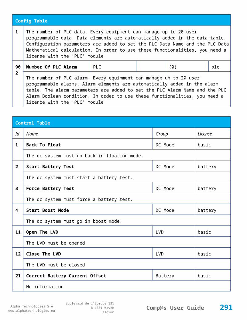
Alpha Technologies S.A.www.alphatechnologies.eu
Alpha Technologies S.A.www.alphatechnologies.eu
Comp@s User GuideBoulevard de l’Europe 131
B-1301 WavreBelgium
Config Table
The voltage at which any battery test must be stopped.
71 Battery Test Discharge Ratio
Battery Battery Test % 0/100 (0) battery
The ratio of the battery capacity to discharge. If 30 is set, 30% of the battery will be discharged during the test
72 Battery Test Interval Battery Battery Test day 0/3000 (0) battery
The number of days between two automatically started battery test. If this parameter is set to 0, the battery test is not started automatically. The user can remotely or locally start or force this test.
73 Battery Test Discharge Current
Battery Battery Test Ampere 3/100 (1000) battery
The current at which the battery must be discharged during a battery test. The monitoring regulates the bus voltage in order to satisfy this condition. The load current must be of course higher than this parameter.
74 Battery Test Minimal Discharge Current
Battery Battery Test Ampere 2/90 (2) battery
The battery current under which the battery test must be stopped because the load is too low.
75 Battery Test Time Out Battery Battery Test minute 1/5000 (10) battery
The timeout in minute after which the battery test must be stopped.
76 Battery Test Requested Minutes Without Mains Failure
Battery Battery Test minute 0/5000 (1440) battery
The minimal time in minute without mains failure in order to allow a battery start. This parameter is not taken into account when the battery test is forced.
77 Battery Test Scheduler Cron Rule
Battery Battery Test basic
83 Smart Energy Boolean Condition
Smart Energy
asset
This is the boolean condition which allows or not to automatically optimize the number of rectifier in remote off.
86 Battery LVD Node Id LVD True/False (False)
basic
This is a list of the node id of the Smart Electronic LVDs, coma separated
91 Digital Input 1 Name Digital Inputs
Digital Input 1 Distribution Breaker Open
basic
291

Alpha Technologies S.A.www.alphatechnologies.eu
Alpha Technologies S.A.www.alphatechnologies.eu
Comp@s User GuideBoulevard de l’Europe 131
B-1301 WavreBelgium
Config Table
The name of the digital input 1
92 Digital Input 1 Normally Closed
Digital Inputs
Digital Input 1 True/False (True)
basic
True/False value defining if the digital input 1 is normally closed. If this digital input is not in this default state, the related alarm is set.
93 Digital Input 2 Name Digital Inputs
Digital Input 2 Battery Breaker Open
basic
The name of the digital input 2
94 Digital Input 2 Normally Closed
Digital Inputs
Digital Input 2 True/False (True)
basic
True/False value defining if the digital input 2 is normally closed. If this digital input is not in this default state, the related alarm is set.
95 Digital Input 3 Name Digital Inputs
Digital Input 3 Digital Input 3 basic
The name of the digital input 3
96 Digital Input 3 Normally Closed
Digital Inputs
Digital Input 3 True/False (True)
basic
True/False value defining if the digital input 3 is normally closed. If this digital input is not in this default state, the related alarm is set.
97 Digital Input 4 Name Digital Inputs
Digital Input 4 Digital Input 4 basic
The name of the digital input 4
98 Digital Input 4 Normally Closed
Digital Inputs
Digital Input 4 True/False (True)
basic
True/False value defining if the digital input 4 is normally closed. If this digital input is not in this default state, the related alarm is set.
99 Digital Input 5 Name Digital Inputs
Digital Input 5 Digital Input 5 basic
The name of the digital input 5
100
Digital Input 5 Normally Closed
Digital Inputs
Digital Input 5 True/False (True)
basic
True/False value defining if the digital input 5 is normally closed. If this digital input is not in this default state, the related alarm is set.
101
Digital Input 6 Name Digital Inputs
Digital Input 6 Digital Input 6 basic
292
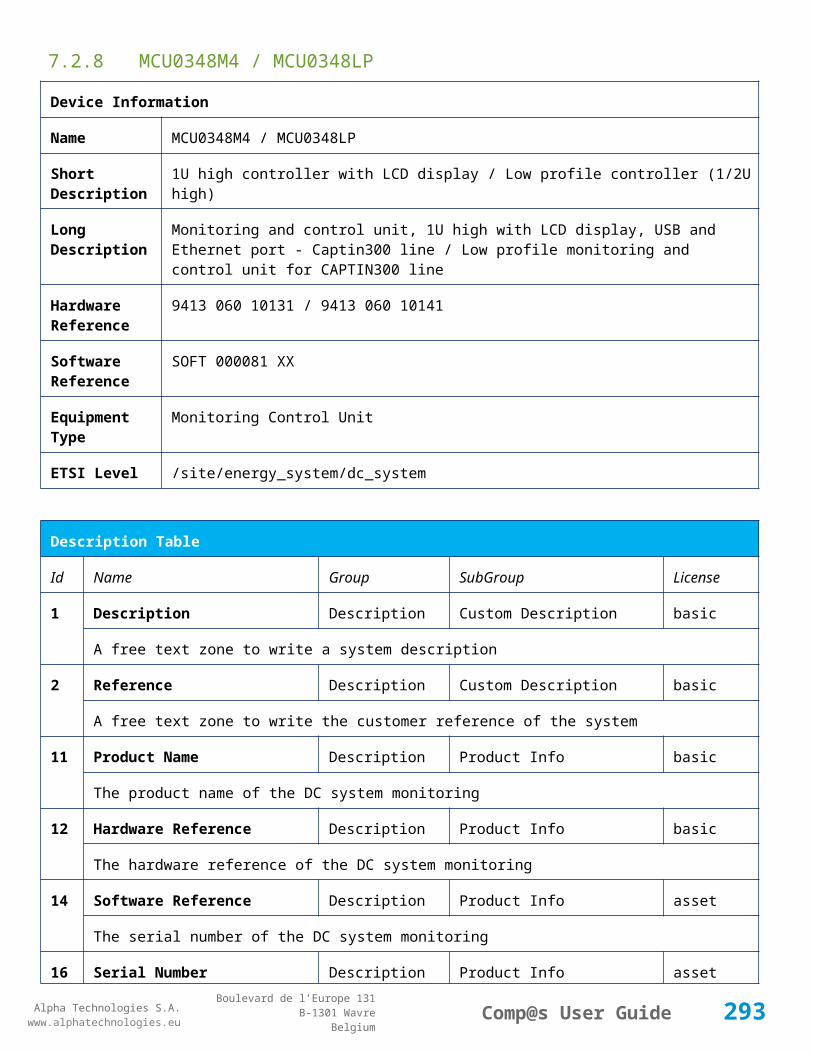
Alpha Technologies S.A.www.alphatechnologies.eu
Alpha Technologies S.A.www.alphatechnologies.eu
Comp@s User GuideBoulevard de l’Europe 131
B-1301 WavreBelgium
Config Table
The name of the digital input 6
102
Digital Input 6 Normally Closed
Digital Inputs
Digital Input 6 True/False (True)
basic
True/False value defining if the digital input 6 is normally closed. If this digital input is not in this default state, the related alarm is set.
103
Digital Input 7 Name Digital Inputs
Digital Input 7 Digital Input 7 basic
The name of the digital input 7
104
Digital Input 7 Normally Closed
Digital Inputs
Digital Input 7 True/False (True)
basic
True/False value defining if the digital input 7 is normally closed. If this digital input is not in this default state, the related alarm is set.
105
Digital Input 8 Name Digital Inputs
Digital Input 8 Digital Input 8 basic
The name of the digital input 8
106
Digital Input 8 Normally Closed
Digital Inputs
Digital Input 8 True/False (True)
basic
True/False value defining if the digital input 8 is normally closed. If this digital input is not in this default state, the related alarm is set.
111
Dry Alarm 1 Alternative Boolean Condition
Relays Relay 1 plc
Another Boolean condition to activate the dry alarm relay 1. The way to define boolean condition is detailed in the PLC chapter.
112
Dry Alarm 2 Alternative Boolean Condition
Relays Relay 2 plc
Another Boolean condition to activate the dry alarm relay 2. The way to define boolean condition is detailed in the PLC chapter.
113
Dry Alarm 3 Alternative Boolean Condition
Relays Relay 3 plc
Another Boolean condition to activate the dry alarm relay 3. The way to define boolean condition is detailed in the PLC chapter.
114
Dry Alarm 4 Alternative Boolean Condition
Relays Relay 4 plc
Another Boolean condition to activate the dry alarm relay 4. The way to define boolean condition is detailed in the PLC chapter.
293

Alpha Technologies S.A.www.alphatechnologies.eu
Alpha Technologies S.A.www.alphatechnologies.eu
Comp@s User GuideBoulevard de l’Europe 131
B-1301 WavreBelgium
Config Table
131
Ambient Temperature Low
Sensors Temperature degree C basic
The temperature under which the alarm 'Ambiant Temperature Too Low' must be set.
132
Ambient Temperature High
Sensors Temperature degree C basic
The temperature under which the alarm 'Ambiant Temperature Too Low' must be set.
133
Ambient Temperature Hysteresis
Sensors Temperature degree C basic
The hysteresis on the 'Battery Temperature Too High' and 'Battery Temperature Too Low' alarms.
521
Read Access User Numbers
Generic Allowed Users (1,2,3,4,5) basic
The list of the user numbers which have read access to this equipment. The user numbers are coma separated. The accepted user id are 1,2,3,4 and 5. Ex: 1,3,4
522
Write Access User Numbers
Generic Allowed Users () basic
The list of the user numbers which have write access to this equipment. This means that these users can modify the configuration element, the alarm settings and use the control elements. The user numbers are coma separated. The accepted user ids are 1,2,3,4 and 5. Ex: 1,3,4
601
Event Table Length Generic Events 10/4000 (100) basic
The maximum length of the table. The value must be comprised between 10 and 4000
602
Event Table Length By Rectifier
Generic Events 10/4000 (100) basic
The maximum length of the table. The value must be comprised between 10 and 4000
901
Number Of PLC Data PLC (0) plc
The number of PLC data. Every equipment can manage up to 20 user programmable data. Data elements are automatically added in the data table. Configuration parameters are added to set the PLC Data Name and the PLC Data Mathematical calculation. In order to use these functionalities, you need a license with the 'PLC' module
902
Number Of PLC Alarm PLC (0) plc
The number of PLC alarm. Every equipment can manage up to 20 user programmable alarms. Alarm elements are automatically added in the alarm table. The alarm parameters are added to set the PLC Alarm Name and the PLC Alarm Boolean condition. In order to use these functionalities, you need a licence with the 'PLC' module
294

Alpha Technologies S.A.www.alphatechnologies.eu
Alpha Technologies S.A.www.alphatechnologies.eu
Comp@s User GuideBoulevard de l’Europe 131
B-1301 WavreBelgium
Control Table
Id Name Group SubGroup License
1 Back To Float System basic
The dc system must go back in floating mode.
2 Start Battery Test System battery
The dc system must start a battery test.
3 Force Battery Test System battery
The dc system must force a battery test.
4 Start Boost Mode System battery
The dc system must go in boost mode.
11 Open The LVD LVD basic
Try to open the LVD. It could not work if the LVD is electronic, and the request will be canceled after 15 sec.
12 Close The LVD LVD basic
The LVD must be closed
21 Correct Battery Current Offset Battery basic
31 Reset Battery Current Integration Battery basic
Reset the integration of the battery current.
41 Reset Last Battery Test State Battery battery
Reset the state of the last battery test. If an alarm 'Battery Last Test Failed' is set, the alarm will be cleared.
51 Save Configuration In MCU Save basic
Save configuration parameters in the MCU microcontroller. If comp@s is not present, the system will be correctly managed.
55 Set MCU Specific Configuration Id Advanced Factory basic
This control allows to reconfigure the MCU to support specific hardware configuration, with embedded distribution for example
61 Set Digital Input 4 Counter Value Digital Inputs Digital Input 4 basic
Set Counter Value
295
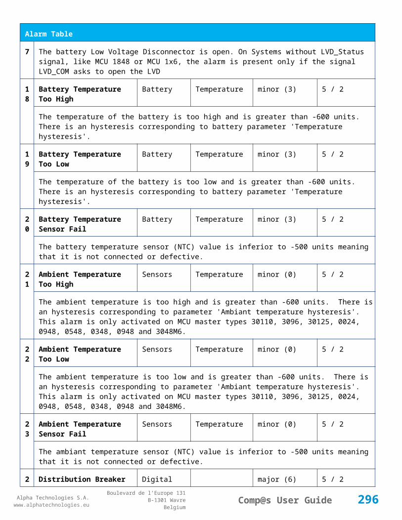
Alpha Technologies S.A.www.alphatechnologies.eu
Alpha Technologies S.A.www.alphatechnologies.eu
Comp@s User GuideBoulevard de l’Europe 131
B-1301 WavreBelgium
Control Table
111
Invert Relay 1 State For X Seconds Relays Relay 1 basic
Generate Pulse on relay 1
112
Invert Relay 2 State For X Seconds Relays Relay 2 basic
Generate Pulse on relay 2
113
Invert Relay 3 State For X Seconds Relays Relay 3 basic
Generate Pulse on relay 3
114
Invert Relay 4 State For X Seconds Relays Relay 4 basic
Generate Pulse on relay 4
501
Clear My Events Generic Events basic
By writing '1' to this control element, all the events of this equipment will be cleared.
502
Clear All Events Generic Events basic
By writing '1' to this control element, all the events of this equipment and all the events of all the sub-equipments will be cleared.
511
Add Event Generic Events basic
This control element adds an event of severity none. The event name is the text written to this control element
512
Add Major Event Generic Events basic
This control element adds an event of severity major. The event name is the text written to this control element
521
Reset Default Names And Groups Generic Renaming basic
This control element resets all the element Names, Groups and Subgroups to default values for this equipment
522
Reset Default Names And Groups Recursive Generic Renaming basic
This control element resets all the element Names, Groups and Subgroups to default values for this equipment and all sub equipments
7.2.11 MCU0948M4 / MCU0948M4LP
Device Information
Name MCU0948M4 / MCU0948M4LP
Short 1U high controller with LCD display / Low profile controller (1/2U high)
296
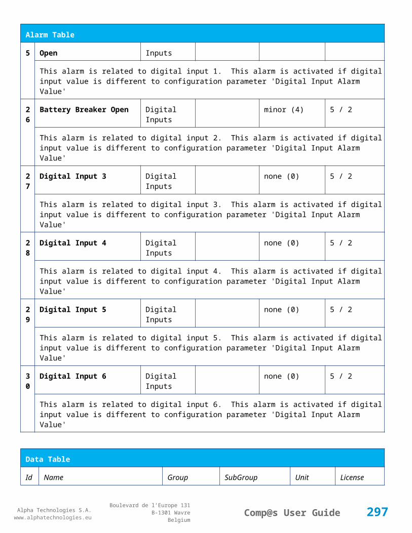
Alpha Technologies S.A.www.alphatechnologies.eu
Alpha Technologies S.A.www.alphatechnologies.eu
Comp@s User GuideBoulevard de l’Europe 131
B-1301 WavreBelgium
Device Information
Description
Long Description
Monitoring and control unit, 1U high with LCD display, USB and Ethernet port - Captin FA, Captin BW, ACE102FALP and ACE094 lines / Low profile monitoring and control unit, 0.5U high, USB and Ethernet port - CAPTIN FA, CAPTIN BW lines
Hardware Reference
9413 060 95051 / 9413 060 95081
Software Reference
SOFT 000030 XX
Equipment Type
Monitoring Control Unit
ETSI Level /site/energy_system/dc_system
Description Table
Id Name Group SubGroup License
1 Description Description Custom Description basic
A free text zone to write a system description
2 Reference Description Custom Description basic
A free text zone to write the customer reference of the system
11 Product Name Description Product Info basic
The product name of the DC system monitoring
12 Hardware Reference Description Product Info basic
The hardware reference of the DC system monitoring
14 Software Reference Description Product Info asset
The serial number of the DC system monitoring
16 Serial Number Description Product Info asset
The serial number of the DC system monitoring
18 Manufacturing Date Description Product Info asset
The production date of the DC system monitoring
297

Alpha Technologies S.A.www.alphatechnologies.eu
Alpha Technologies S.A.www.alphatechnologies.eu
Comp@s User GuideBoulevard de l’Europe 131
B-1301 WavreBelgium
Alarm Table
Id Name Group SubGroup Severity Type (Level)
Set/Clear Delay
1 DC Bus Extra Low DC Bus major (6) 5 / 2
The bus voltage is extra low. The alarm is set when the bus voltage is lower than the configuration parameter 'DC Bus Voltage Extra Low'. There is an hysteresis on the alarm : 'DC Bus Voltage Extra Low Hysteresis'. The alarm is not activated when DC mode is BATTERY TEST
2 DC Bus Low DC Bus minor (4) 5 / 2
The bus voltage is low. The alarm is set when the bus voltage is lower than the configuration parameter 'DC Bus Voltage Low'. There is an hysteresis on the alarm : 'DC Bus Voltage Low Hysteresis'
3 DC Bus High DC Bus minor (4) 5 / 2
The bus voltage is high. The alarm is set when the bus voltage is higher than the configuration paramenter 'DC Bus Voltage High'. There is an hysterisis on the alarm : 'DC Bus Voltage High Hysteresis'
4 DC Bus Extra High DC Bus major (6) 5 / 2
The bus voltage is extra high. The alarm is set when the bus voltage is higher than the configuration paramenter 'DC Bus Voltage Extra High'. There is an hysterisis on the alarm : 'DC Bus Voltage Extra High Hysteresis'
5 DC Bus Voltage Sense Failure
DC Bus major (6) 5 / 2
The DC bus voltage sense is defective. The DC bus voltage is unconnected or unconfigured.
6 Mains Failure AC Bus minor (4) 5 / 2
The number of active rectifiers is equal to 0 and the number of rectifiers in AC failure is greater than 0.
7 Mains Partial Failure AC Bus minor (4) 10 / 2
The number of active rectifiers is greater than 0 and the number of rectifiers in AC failure is greater than 0. Some rectifiers are in AC Failure. It may be caused by an open breaker, a real phase failure, or by a rectifier failure.
8 Mains Low AC Bus warning (2) 10 / 2
The main voltage is low on one or more phases. No rectifier is in AC failure. If MCU master type is 30110, 3096 or 3048M6, an hysteresis _phase123Hysteresis is added to the voltage lower limit
10
One Rectifier Failure Rectifiers minor (4) 5 / 2
One rectifier must be replaced or is not powered correctly. The DC fail alarm of the rectifier is set. The number of rectifier with DC Failure is higher than 0, there is no mains failure, and the 'More Than One Rectifier Failure alarm is not set.'
11
More Than One Rectifier Failure
Rectifiers major (6) 10 / 2
298

Alpha Technologies S.A.www.alphatechnologies.eu
Alpha Technologies S.A.www.alphatechnologies.eu
Comp@s User GuideBoulevard de l’Europe 131
B-1301 WavreBelgium
Alarm Table
There is no mains failure and number of rectifier failures is greater than 1.
12
Missing Rectifiers Rectifiers major (6) 5 / 2
There is not enough rectifier according to the configuration parameter : 'Minimal Number Of Rectifier'
13
Battery Last Test Failed Battery Battery Test minor (3) 5 / 2
The last battery test did not succeed and was not cancelled. Maybe the battery should be replaced.
14
Battery On Discharge Battery minor (4) 10 / 2
The battery is discharging. This means that the load is too high for the installed rectifiers. This alarm is inactive when the system in AC Failure or during a battery test. There is an hysteresis corresponding to battery parameter 'Is discharging current hysteresis'.
17
Battery LVD Relay Open LVD major (6) 5 / 2
The battery Low Voltage Disconnector is open. On Systems without LVD_Status signal, like MCU 1848 or MCU 1x6, the alarm is present only if the signal LVD_COM asks to open the LVD
18
Battery Temperature Too High
Battery Temperature minor (3) 5 / 2
The temperature of the battery is too high and is greater than -600 units. There is an hysteresis corresponding to battery parameter 'Temperature hysteresis'.
19
Battery Temperature Too Low
Battery Temperature minor (3) 5 / 2
The temperature of the battery is too low and is greater than -600 units. There is an hysteresis corresponding to battery parameter 'Temperature hysteresis'.
20
Battery Temperature Sensor Fail
Battery Temperature minor (3) 5 / 2
The battery temperature sensor (NTC) value is inferior to -500 units meaning that it is not connected or defective.
21
Ambient Temperature Too High
Sensors Temperature minor (0) 5 / 2
The ambient temperature is too high and is greater than -600 units. There is an hysteresis corresponding to parameter 'Ambiant temperature hysteresis'. This alarm is only activated on MCU master types 30110, 3096, 30125, 0024, 0948, 0548, 0348, 0948 and 3048M6.
22
Ambient Temperature Too Low
Sensors Temperature minor (0) 5 / 2
The ambient temperature is too low and is greater than -600 units. There is an hysteresis corresponding to parameter 'Ambiant temperature hysteresis'. This alarm is only activated on MCU master types 30110, 3096, 30125, 0024, 0948, 0548, 0348, 0948 and 3048M6.
2 Ambient Temperature Sensors Temperature minor (0) 5 / 2
299

Alpha Technologies S.A.www.alphatechnologies.eu
Alpha Technologies S.A.www.alphatechnologies.eu
Comp@s User GuideBoulevard de l’Europe 131
B-1301 WavreBelgium
Alarm Table
3 Sensor Fail
The ambiant temperature sensor (NTC) value is inferior to -500 units meaning that it is not connected or defective.
25
Distribution Breaker Open Digital Inputs major (6) 5 / 2
This alarm is related to digital input 1. This alarm is activated if digital input value is different to configuration parameter 'Digital Input Alarm Value'
26
Battery Breaker Open Digital Inputs minor (4) 5 / 2
This alarm is related to digital input 2. This alarm is activated if digital input value is different to configuration parameter 'Digital Input Alarm Value'
27
Digital Input 3 Digital Inputs none (0) 5 / 2
This alarm is related to digital input 3. This alarm is activated if digital input value is different to configuration parameter 'Digital Input Alarm Value'
28
Digital Input 4 Digital Inputs none (0) 5 / 2
This alarm is related to digital input 4. This alarm is activated if digital input value is different to configuration parameter 'Digital Input Alarm Value'
Data Table
Id Name Group SubGroup Unit License
1 DC Mode System basic
The DC system can have 4 values: 'FLOAT', 'BOOST', 'BATTERY_TEST', 'AC_FAILURE' or SAFE
2 Previous DC Mode System basic
The previous value of the DC Mode
11 Bus Voltage DC Bus Volt basic
The DC bus voltage in volt.
12 Ratio Delivered On Available Power
System % basic
This is the ratio of the delivered power divided by the installed power, in %.
13 Minutes Since Last AC Failure Begin
AC Bus minute basic
The number of minute since the last AC Failure begin
14 Minutes Since Last AC Failure AC Bus minute basic
300

Alpha Technologies S.A.www.alphatechnologies.eu
Alpha Technologies S.A.www.alphatechnologies.eu
Comp@s User GuideBoulevard de l’Europe 131
B-1301 WavreBelgium
Data Table
End
The number of minute since the last AC Failure end
21 Rectifiers Output Power Rectifiers Watt basic
The sum of the delivered rectifier power
22 Rectifiers Output Current Rectifiers Ampere basic
The sum of the delivered rectifier current
23 Rectifiers Output Power Max Rectifiers Watt basic
The sum of the deliverable rectifier power
24 Rectifiers Output Current Max Rectifiers Ampere basic
The sum of the deliverable rectifier current
31 Number Of Rectifier Max Rectifiers Numbers basic
The maximum possible number of rectifier in this dc system
32 Number Of Present Rectifier Rectifiers Numbers basic
The actual number of present rectifier in this dc system
33 Number Of Absent Rectifier Rectifiers Numbers basic
The actual number of absent rectifier in this dc system
34 Number Of Active Rectifier Rectifiers Numbers basic
The actual number of active rectifier in this dc system. An active rectifier is a rectifier which is present, DC OK, AC OK and not in remote off.
35 Number Of AC-Fail Rectifier Rectifiers Numbers basic
The actual number or rectifier in AC Failure.
36 Number Of DC-Fail Rectifier Rectifiers Numbers basic
The actual number or rectifier with DC Failure.
37 Number Of Remote Off Rectifier Rectifiers Numbers basic
The actual number or rectifier in remote off.
38 Number Of Over Temperature Rectifier
Rectifiers Numbers basic
The actual number or rectifier in OVer Temperature.
301

Alpha Technologies S.A.www.alphatechnologies.eu
Alpha Technologies S.A.www.alphatechnologies.eu
Comp@s User GuideBoulevard de l’Europe 131
B-1301 WavreBelgium
Data Table
41 Mains Phase 1 Voltage AC Bus Volt basic
The voltage on AC phase 1
42 Mains Phase 2 Voltage AC Bus Volt basic
The voltage on AC phase 2
43 Mains Phase 3 Voltage AC Bus Volt basic
The voltage on AC phase 3
51 Load Power Load Watt basic
Estimation of the load power consumption
52 Load Current Load Ampere basic
Estimation of the load current consumption
61 Battery Input Current Battery Ampere basic
Measurement of the battery input current. A negative value means that the battery is discharging
62 Battery Input Power Battery Watt basic
Measurement of the battery input power. A negative value means that the battery is discharging
71 Battery Temperature Battery Temperature degree C basic
The battery temperature
72 Battery Test State Battery Battery Test basic
This is about the result of the last battery test. 9 values are possible : NEVER_TESTED, SUCCESS, ON_GOING, FAILED_TIMEOUT, FAILED_VBUS_TOO_LOW, FAILED_LOAD_TOO_LOW, FAILED_AC_FAILURE, FAILED_CANCELED, FAILED_LVD_OPENED
73 Battery Test Discharged Capacity Ratio
Battery Battery Test % basic
This is the battery capacity, in percent, discharged during the last battery test. This value is updated at the end of the battery test.
74 Battery Test Discharged Capacity
Battery Battery Test Ah basic
This is the battery capacity, in ampere hour, discharged during the last battery test. This value is updated at the end of the battery test.
75 Battery Test Final Voltage Battery Battery Test % basic
This is the bus voltage at the end of the last battery test. This value is updated at the end of the battery test.
302

Alpha Technologies S.A.www.alphatechnologies.eu
Alpha Technologies S.A.www.alphatechnologies.eu
Comp@s User GuideBoulevard de l’Europe 131
B-1301 WavreBelgium
Data Table
81 Previous Battery Test State Battery Battery Test basic
The result of the previous battery test
82 Minutes Since Last Test Battery Battery Battery Test basic
The number of minute without battery test
84 Next Scheduled Battery Test Battery Battery Test basic
The date and time of the next time the scheduled battery test will run
91 Battery Charge Capacity Battery % basic
The battery charge capacity, calculated by integration of the current.
92 Calculated Autonomy Battery minute basic
Calculation of the remaining autonomy
93 Battery Current Integration Battery As basic
Actual value of the integration of the current, in Ampere * second
94 Battery Current Integration Battery Ah basic
Actual value of the integration of the current, in Ampere * hour
101
LVD State LVD basic
Actual state of the LVD
111
Relay 1 State Relays Relay 1 basic
Actual state of the Relay 1
112
Relay 2 State Relays Relay 2 basic
Actual state of the Relay 2
113
Relay 3 State Relays Relay 3 basic
Actual state of the Relay 3
114
Relay 4 State Relays Relay 4 basic
Actual state of the Relay 3
121
Efficiency Optimized Number Of Rectifier
Smart Energy asset
The optimal number of ON rectifier for Efficiency Optimization
12 System Loss Without Smart Energy Watt underdev
303

Alpha Technologies S.A.www.alphatechnologies.eu
Alpha Technologies S.A.www.alphatechnologies.eu
Comp@s User GuideBoulevard de l’Europe 131
B-1301 WavreBelgium
Data Table
2 Optimisation
Estimation of the losses without optimisation
123
System Loss With Optimisation Smart Energy Watt underdev
Estimation of the losses with optimisation
124
Rectifier Model Used For Calculation
Smart Energy asset
The rectifier model used
125
Smart Energy Savings Smart Energy Watt asset
Estimation of the losses with optimisation
151
Ambient Temperature Sensors Temperature degree C basic
The ambiant temperature (second temperature sense)
161
Voltage 1 Sensors Voltage 1 Volt basic
The voltage measured by the sense 1. Can be used for battery symmetry measurement. Calculation can be done with the PLC
162
Voltage 2 Sensors Voltage 2 Volt basic
The voltage measured by the sense 2. Can be used for battery symmetry measurement. Calculation can be done with the PLC
163
Voltage 3 Sensors Voltage 3 Volt basic
The voltage measured by the sense 3. Can be used for battery symmetry measurement. Calculation can be done with the PLC
204
Pulse Counter 4 Sensors Pulse Counter 4 basic
The counter value of the digital input 4.
Config Table
Id Name Group SubGroup Unit Range: Min/Max (default)
License
1 DC Bus Float Voltage at 25 degC
DC Bus Volt 40/60 (54) basic
The floating dc bus voltage of the system at 25 Celsius degree
2 DC Bus Voltage Extra DC Bus Alarm Parameters Volt 40/60 (45) basic
304

Alpha Technologies S.A.www.alphatechnologies.eu
Alpha Technologies S.A.www.alphatechnologies.eu
Comp@s User GuideBoulevard de l’Europe 131
B-1301 WavreBelgium
Config Table
Low
The bus voltage under which the alarm 'DC Bus Voltage Extra Low' is set.
3 DC Bus Voltage Extra Low Hysteresis
DC Bus Alarm Parameters Volt 0/5 (1) basic
The voltage hysteresis on the alarm 'DC Bus Voltage Extra Low'.
4 DC Bus Voltage Low DC Bus Alarm Parameters Volt 40/60 (48) basic
The bus voltage under which the alarm 'DC Bus Voltage Low' is set.
5 DC Bus Voltage Low Hysteresis
DC Bus Alarm Parameters Volt 0/5 (0.5) basic
The voltage hysteresis on the alarm 'DC Bus Voltage Low
6 DC Bus Voltage High DC Bus Alarm Parameters Volt 40/60 (56.5) basic
The bus voltage over which the alarm 'DC Bus Voltage High' is set.
7 DC Bus Voltage High Hysteresis
DC Bus Alarm Parameters Volt 0/5 (0.5) basic
The voltage hysteresis on the alarm 'DC Bus Voltage High
8 DC Bus Voltage Extra High
DC Bus Alarm Parameters Volt 40/60 (58) basic
The bus voltage over which the alarm 'DC Bus Voltage Extra High' is set.
9 DC Bus Voltage Extra High Hysteresis
DC Bus Alarm Parameters Volt 0/5 (0.5) basic
The voltage hysteresis on the alarm 'DC Bus Voltage Extra High
10 LVD Disconnect Voltage LVD Volt 0/50 (43.2) basic
The dc bus voltage under which the battery must be disconnected of the bus. This allows preserving the battery life. The load will be unpowered.
11 LVD Disconnect Delay LVD second 1/2000 (1) basic
The delay in second before disconnecting the battery if the dc bus voltage is under the configured disconnected voltage. This avoids disconnection during a low bus transient.
21 Temperature Compensation Slope
Battery Temperature Compensation
mV/degree -1000/0 (-72) basic
The slope of the battery temperature compensation in mv/degree. For a 48V system, -72mV/degree is often used.
22 Maximum Positive Battery Temperature Volt 0/10 (3) basic
305

Alpha Technologies S.A.www.alphatechnologies.eu
Alpha Technologies S.A.www.alphatechnologies.eu
Comp@s User GuideBoulevard de l’Europe 131
B-1301 WavreBelgium
Config Table
Temperature Compensation
Compensation
The maximal allowed positive compensation.
23 Maximum Negative Temperature Compensation
Battery Temperature Compensation
Volt -10/0 (-3) basic
The maximal allowed negative compensation.
25 Minimal Number Of Present Rectifiers
Rectifiers Alarm Parameters 0/100 (0) basic
The minimal number of rectifier which must be present. If there is less present rectifiers, the alarm 'Missing Rectifiers' is set.
26 Rectifier Model Rectifiers basic
The rectifier model
27 Forced Remote Off Rectifers
Rectifiers basic
A list of rectifier which are forced in remote off. The id of the rectifier must be coma separated. Ex: 1,3 will maintain rectifier 1 and 3 off.
31 Battery Charge Current Limit
Battery Battery Charge Parameters
Ampere 0.5/1000 (1000) basic
The maximal battery current when the battery is charging. The monitoring regulates the bus voltage in order to satisfy this condition. This parameter is often equal to the nominal battery capacity divided by 10.
32 Battery String Capacity Battery Ah 3/1000 (100) basic
The battery capacity in Ah.
33 Battery Temperature Low
Battery Alarm Parameters degree C -100/20 (0) basic
The temperature under which the alarm 'Battery Temperature Too Low' must be set.
34 Battery Temperature High
Battery Alarm Parameters degree C 5/100 (40) basic
The temperature over which the alarm 'Battery Temperature Too High' must be set.
35 Battery Temperature Hysteresis
Battery Alarm Parameters degree C 0/10 (2) basic
The hysteresis on the 'Battery Temperature Too High' and 'Battery Temperature Too Low' alarms.
36 Minimal Current For Battery Alarm Parameters Ampere 0/1000 (2) basic
306

Alpha Technologies S.A.www.alphatechnologies.eu
Alpha Technologies S.A.www.alphatechnologies.eu
Comp@s User GuideBoulevard de l’Europe 131
B-1301 WavreBelgium
Config Table
Discharging Alarm
The minimal discharging current to set the 'Battery On Discharge' alarm.
37 Current Hysteresis For Discharging Alarm
Battery Alarm Parameters Ampere 0/50 (0.5) basic
The hysteresis on the 'Battery On Discharge' alarm.
51 Boost Automatic Battery Boost False/False (False)
battery
The boost mode must be automatically after the fact that during a mains failure, the bus voltage went under the configured 'Boost Activation Low Voltage'. This allows charging the battery faster.
52 Boost Activation Low Voltage
Battery Boost Volt 43/50 (46) battery
The voltage under which the boost mode can be activated.
53 Boost Termination Voltage
Battery Boost Volt 50/58 (56.4) battery
The voltage over which the system must go back to floating mode.
54 Boost Termination Current
Battery Boost Ampere 0/100 (2) battery
The battery charging current under which the system must go back to floating mode.
55 Boost Termination Time Battery Boost minute 10/240 (120) battery
The time in minute after which the system must go back in floating mode.
70 Battery Test End Voltage
Battery Battery Test Volt 30/60 (46) battery
The voltage at which any battery test must be stopped.
71 Battery Test Discharge Ratio
Battery Battery Test % 0/100 (0) battery
The ratio of the battery capacity to discharge. If 30 is set, 30% of the battery will be discharged during the test
72 Battery Test Interval Battery Battery Test day 0/3000 (0) battery
The number of days between two automatically started battery test. If this parameter is set to 0, the battery test is not started automatically. The user can remotely or locally start or force this test.
73 Battery Test Discharge Current
Battery Battery Test Ampere 3/100 (1000) battery
The current at which the battery must be discharged during a battery test. The monitoring regulates the
307

Alpha Technologies S.A.www.alphatechnologies.eu
Alpha Technologies S.A.www.alphatechnologies.eu
Comp@s User GuideBoulevard de l’Europe 131
B-1301 WavreBelgium
Config Table
bus voltage in order to satisfy this condition. The load current must be of course higher than this parameter.
74 Battery Test Minimal Discharge Current
Battery Battery Test Ampere 2/90 (2) battery
The battery current under which the battery test must be stopped because the load is too low.
75 Battery Test Time Out Battery Battery Test minute 1/5000 (10) battery
The timeout in minute after which the battery test must be stopped.
76 Battery Test Requested Minutes Without Mains Failure
Battery Battery Test minute 0/5000 (1440) battery
The minimal time in minute without mains failure in order to allow a battery start. This parameter is not taken into account when the battery test is forced.
77 Battery Test Scheduler Cron Rule
Battery Battery Test basic
83 Smart Energy Boolean Condition
Smart Energy
asset
This is the boolean condition which allows or not to automatically optimize the number of rectifier in remote off.
86 Battery LVD Node Id LVD True/False (False)
basic
This is a list of the node id of the Smart Electronic LVDs, coma separated
91 Digital Input 1 Name Digital Inputs
Digital Input 1 Distribution Breaker Open
basic
The name of the digital input 1
92 Digital Input 1 Normally Closed
Digital Inputs
Digital Input 1 True/False (True)
basic
True/False value defining if the digital input 1 is normally closed. If this digital input is not in this default state, the related alarm is set.
93 Digital Input 2 Name Digital Inputs
Digital Input 2 Battery Breaker Open
basic
The name of the digital input 2
94 Digital Input 2 Normally Closed
Digital Inputs
Digital Input 2 True/False (True)
basic
308
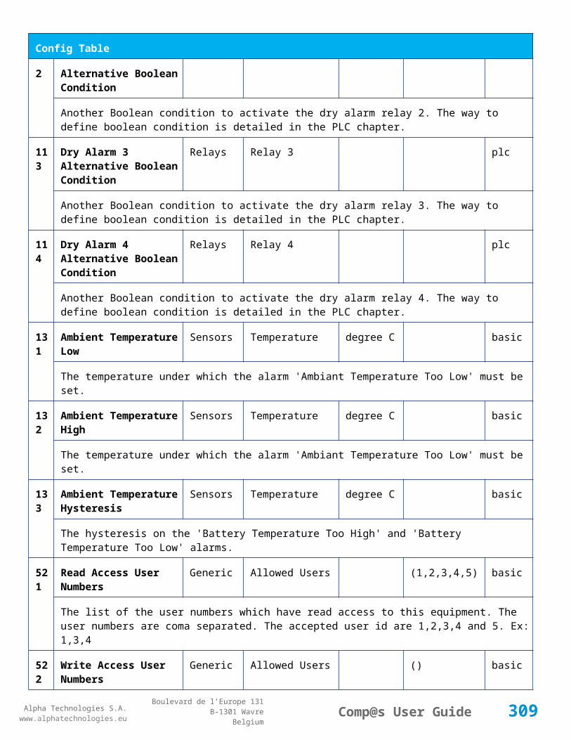
Alpha Technologies S.A.www.alphatechnologies.eu
Alpha Technologies S.A.www.alphatechnologies.eu
Comp@s User GuideBoulevard de l’Europe 131
B-1301 WavreBelgium
Config Table
True/False value defining if the digital input 2 is normally closed. If this digital input is not in this default state, the related alarm is set.
95 Digital Input 3 Name Digital Inputs
Digital Input 3 Digital Input 3 basic
The name of the digital input 3
96 Digital Input 3 Normally Closed
Digital Inputs
Digital Input 3 True/False (True)
basic
True/False value defining if the digital input 3 is normally closed. If this digital input is not in this default state, the related alarm is set.
97 Digital Input 4 Name Digital Inputs
Digital Input 4 Digital Input 4 basic
The name of the digital input 4
98 Digital Input 4 Normally Closed
Digital Inputs
Digital Input 4 True/False (True)
basic
True/False value defining if the digital input 4 is normally closed. If this digital input is not in this default state, the related alarm is set.
111
Dry Alarm 1 Alternative Boolean Condition
Relays Relay 1 plc
Another Boolean condition to activate the dry alarm relay 1. The way to define boolean condition is detailed in the PLC chapter.
112
Dry Alarm 2 Alternative Boolean Condition
Relays Relay 2 plc
Another Boolean condition to activate the dry alarm relay 2. The way to define boolean condition is detailed in the PLC chapter.
113
Dry Alarm 3 Alternative Boolean Condition
Relays Relay 3 plc
Another Boolean condition to activate the dry alarm relay 3. The way to define boolean condition is detailed in the PLC chapter.
114
Dry Alarm 4 Alternative Boolean Condition
Relays Relay 4 plc
Another Boolean condition to activate the dry alarm relay 4. The way to define boolean condition is detailed in the PLC chapter.
131
Ambient Temperature Low
Sensors Temperature degree C basic
The temperature under which the alarm 'Ambiant Temperature Too Low' must be set.
309
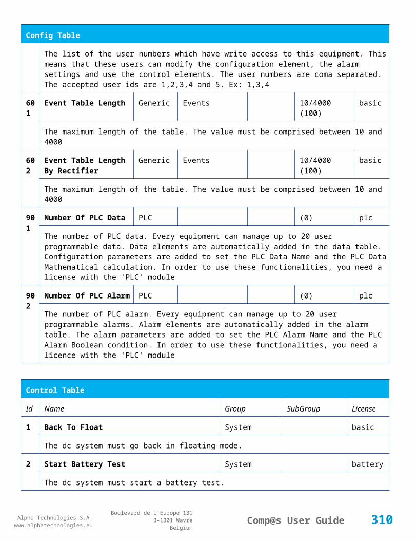
Alpha Technologies S.A.www.alphatechnologies.eu
Alpha Technologies S.A.www.alphatechnologies.eu
Comp@s User GuideBoulevard de l’Europe 131
B-1301 WavreBelgium
Config Table
132
Ambient Temperature High
Sensors Temperature degree C basic
The temperature under which the alarm 'Ambiant Temperature Too Low' must be set.
133
Ambient Temperature Hysteresis
Sensors Temperature degree C basic
The hysteresis on the 'Battery Temperature Too High' and 'Battery Temperature Too Low' alarms.
521
Read Access User Numbers
Generic Allowed Users (1,2,3,4,5) basic
The list of the user numbers which have read access to this equipment. The user numbers are coma separated. The accepted user id are 1,2,3,4 and 5. Ex: 1,3,4
522
Write Access User Numbers
Generic Allowed Users () basic
The list of the user numbers which have write access to this equipment. This means that these users can modify the configuration element, the alarm settings and use the control elements. The user numbers are coma separated. The accepted user ids are 1,2,3,4 and 5. Ex: 1,3,4
601
Event Table Length Generic Events 10/4000 (100) basic
The maximum length of the table. The value must be comprised between 10 and 4000
602
Event Table Length By Rectifier
Generic Events 10/4000 (100) basic
The maximum length of the table. The value must be comprised between 10 and 4000
901
Number Of PLC Data PLC (0) plc
The number of PLC data. Every equipment can manage up to 20 user programmable data. Data elements are automatically added in the data table. Configuration parameters are added to set the PLC Data Name and the PLC Data Mathematical calculation. In order to use these functionalities, you need a license with the 'PLC' module
902
Number Of PLC Alarm PLC (0) plc
The number of PLC alarm. Every equipment can manage up to 20 user programmable alarms. Alarm elements are automatically added in the alarm table. The alarm parameters are added to set the PLC Alarm Name and the PLC Alarm Boolean condition. In order to use these functionalities, you need a licence with the 'PLC' module
Control Table
Id Name Group SubGroup License
1 Back To Float System basic
310
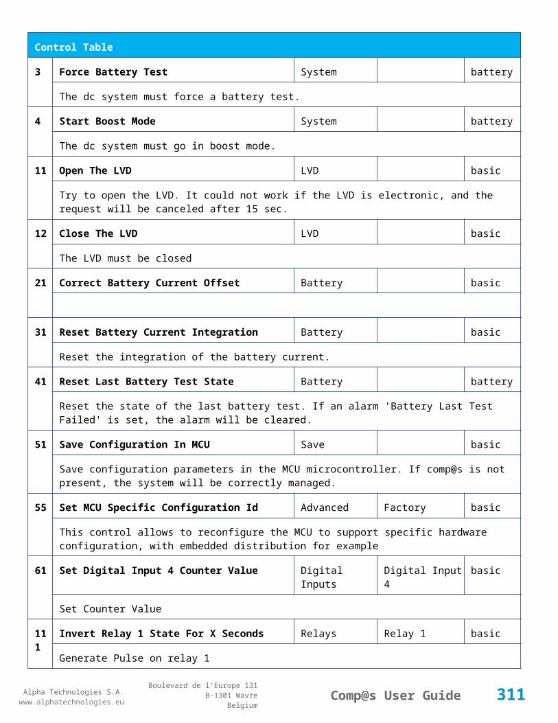
Alpha Technologies S.A.www.alphatechnologies.eu
Alpha Technologies S.A.www.alphatechnologies.eu
Comp@s User GuideBoulevard de l’Europe 131
B-1301 WavreBelgium
Control Table
The dc system must go back in floating mode.
2 Start Battery Test System battery
The dc system must start a battery test.
3 Force Battery Test System battery
The dc system must force a battery test.
4 Start Boost Mode System battery
The dc system must go in boost mode.
11 Open The LVD LVD basic
Try to open the LVD. It could not work if the LVD is electronic, and the request will be canceled after 15 sec.
12 Close The LVD LVD basic
The LVD must be closed
21 Correct Battery Current Offset Battery basic
31 Reset Battery Current Integration Battery basic
Reset the integration of the battery current.
41 Reset Last Battery Test State Battery battery
Reset the state of the last battery test. If an alarm 'Battery Last Test Failed' is set, the alarm will be cleared.
51 Save Configuration In MCU Save basic
Save configuration parameters in the MCU microcontroller. If comp@s is not present, the system will be correctly managed.
55 Set MCU Specific Configuration Id Advanced Factory basic
This control allows to reconfigure the MCU to support specific hardware configuration, with embedded distribution for example
61 Set Digital Input 4 Counter Value Digital Inputs Digital Input 4 basic
Set Counter Value
111
Invert Relay 1 State For X Seconds Relays Relay 1 basic
Generate Pulse on relay 1
311

Alpha Technologies S.A.www.alphatechnologies.eu
Alpha Technologies S.A.www.alphatechnologies.eu
Comp@s User GuideBoulevard de l’Europe 131
B-1301 WavreBelgium
Control Table
112
Invert Relay 2 State For X Seconds Relays Relay 2 basic
Generate Pulse on relay 2
113
Invert Relay 3 State For X Seconds Relays Relay 3 basic
Generate Pulse on relay 3
114
Invert Relay 4 State For X Seconds Relays Relay 4 basic
Generate Pulse on relay 4
501
Clear My Events Generic Events basic
By writing '1' to this control element, all the events of this equipment will be cleared.
502
Clear All Events Generic Events basic
By writing '1' to this control element, all the events of this equipment and all the events of all the sub-equipments will be cleared.
511
Add Event Generic Events basic
This control element adds an event of severity none. The event name is the text written to this control element
512
Add Major Event Generic Events basic
This control element adds an event of severity major. The event name is the text written to this control element
521
Reset Default Names And Groups Generic Renaming basic
This control element resets all the element Names, Groups and Subgroups to default values for this equipment
522
Reset Default Names And Groups Recursive Generic Renaming basic
This control element resets all the element Names, Groups and Subgroups to default values for this equipment and all sub equipments
7.2.12 MCU1848M3 / MCU1848M3D
Device Information
Name MCU1848M3 / MCU1848M3D
Short Description
Controller without LCD display / Controller with LCD display
Long Description
Monitoring and control unit with USB and Ethernet port, no LCD display - ACE153 and ACE156 lines / Monitoring and control unit with LCD display, USB and Ethernet port -
312

Alpha Technologies S.A.www.alphatechnologies.eu
Alpha Technologies S.A.www.alphatechnologies.eu
Comp@s User GuideBoulevard de l’Europe 131
B-1301 WavreBelgium
Device Information
ACE153 and ACE156 line
Hardware Reference
9413 061 85041 / 9413 061 85051
Software Reference
SOFT 000066 XX
Equipment Type
Monitoring Control Unit
ETSI Level /site/energy_system/dc_system
Description Table
Id Name Group SubGroup License
1 Description Description Custom Description basic
A free text zone to write a system description
2 Reference Description Custom Description basic
A free text zone to write the customer reference of the system
11 Product Name Description Product Info basic
The product name of the DC system monitoring
12 Hardware Reference Description Product Info basic
The hardware reference of the DC system monitoring
14 Software Reference Description Product Info asset
The serial number of the DC system monitoring
16 Serial Number Description Product Info asset
The serial number of the DC system monitoring
18 Manufacturing Date Description Product Info asset
The production date of the DC system monitoring
Alarm Table
Id Name Group SubGroup Severity Type (Level)
Set/Clear Delay
313

Alpha Technologies S.A.www.alphatechnologies.eu
Alpha Technologies S.A.www.alphatechnologies.eu
Comp@s User GuideBoulevard de l’Europe 131
B-1301 WavreBelgium
Alarm Table
1 DC Bus Extra Low DC Bus major (6) 5 / 2
The bus voltage is extra low. The alarm is set when the bus voltage is lower than the configuration parameter 'DC Bus Voltage Extra Low'. There is an hysteresis on the alarm : 'DC Bus Voltage Extra Low Hysteresis'. The alarm is not activated when DC mode is BATTERY TEST
2 DC Bus Low DC Bus minor (4) 5 / 2
The bus voltage is low. The alarm is set when the bus voltage is lower than the configuration parameter 'DC Bus Voltage Low'. There is an hysteresis on the alarm : 'DC Bus Voltage Low Hysteresis'
3 DC Bus High DC Bus minor (4) 5 / 2
The bus voltage is high. The alarm is set when the bus voltage is higher than the configuration paramenter 'DC Bus Voltage High'. There is an hysterisis on the alarm : 'DC Bus Voltage High Hysteresis'
4 DC Bus Extra High DC Bus major (6) 5 / 2
The bus voltage is extra high. The alarm is set when the bus voltage is higher than the configuration paramenter 'DC Bus Voltage Extra High'. There is an hysterisis on the alarm : 'DC Bus Voltage Extra High Hysteresis'
5 DC Bus Voltage Sense Failure
DC Bus major (6) 5 / 2
The DC bus voltage sense is defective. The DC bus voltage is unconnected or unconfigured.
6 Mains Failure AC Bus minor (4) 5 / 2
The number of active rectifiers is equal to 0 and the number of rectifiers in AC failure is greater than 0.
7 Mains Partial Failure AC Bus minor (4) 10 / 2
The number of active rectifiers is greater than 0 and the number of rectifiers in AC failure is greater than 0. Some rectifiers are in AC Failure. It may be caused by an open breaker, a real phase failure, or by a rectifier failure.
8 Mains Low AC Bus warning (2) 10 / 2
The main voltage is low on one or more phases. No rectifier is in AC failure. If MCU master type is 30110, 3096 or 3048M6, an hysteresis _phase123Hysteresis is added to the voltage lower limit
10
One Rectifier Failure Rectifiers minor (4) 5 / 2
One rectifier must be replaced or is not powered correctly. The DC fail alarm of the rectifier is set. The number of rectifier with DC Failure is higher than 0, there is no mains failure, and the 'More Than One Rectifier Failure alarm is not set.'
11
More Than One Rectifier Failure
Rectifiers major (6) 10 / 2
There is no mains failure and number of rectifier failures is greater than 1.
314

Alpha Technologies S.A.www.alphatechnologies.eu
Alpha Technologies S.A.www.alphatechnologies.eu
Comp@s User GuideBoulevard de l’Europe 131
B-1301 WavreBelgium
Alarm Table
12
Missing Rectifiers Rectifiers major (6) 5 / 2
There is not enough rectifier according to the configuration parameter : 'Minimal Number Of Rectifier'
13
Battery Last Test Failed Battery Battery Test minor (3) 5 / 2
The last battery test did not succeed and was not cancelled. Maybe the battery should be replaced.
14
Battery On Discharge Battery minor (4) 10 / 2
The battery is discharging. This means that the load is too high for the installed rectifiers. This alarm is inactive when the system in AC Failure or during a battery test. There is an hysteresis corresponding to battery parameter 'Is discharging current hysteresis'.
17
Battery LVD Relay Open LVD major (6) 5 / 2
The battery Low Voltage Disconnector is open. On Systems without LVD_Status signal, like MCU 1848 or MCU 1x6, the alarm is present only if the signal LVD_COM asks to open the LVD
18
Battery Temperature Too High
Battery Temperature minor (3) 5 / 2
The temperature of the battery is too high and is greater than -600 units. There is an hysteresis corresponding to battery parameter 'Temperature hysteresis'.
19
Battery Temperature Too Low
Battery Temperature minor (3) 5 / 2
The temperature of the battery is too low and is greater than -600 units. There is an hysteresis corresponding to battery parameter 'Temperature hysteresis'.
20
Battery Temperature Sensor Fail
Battery Temperature minor (3) 5 / 2
The battery temperature sensor (NTC) value is inferior to -500 units meaning that it is not connected or defective.
25
Distribution Breaker Open Digital Inputs major (6) 5 / 2
This alarm is related to digital input 1. This alarm is activated if digital input value is different to configuration parameter 'Digital Input Alarm Value'
26
Battery Breaker Open Digital Inputs minor (4) 5 / 2
This alarm is related to digital input 2. This alarm is activated if digital input value is different to configuration parameter 'Digital Input Alarm Value'
27
Digital Input 3 Digital Inputs none (0) 5 / 2
This alarm is related to digital input 3. This alarm is activated if digital input value is different to configuration parameter 'Digital Input Alarm Value'
2 Digital Input 4 Digital Inputs none (0) 5 / 2
315

Alpha Technologies S.A.www.alphatechnologies.eu
Alpha Technologies S.A.www.alphatechnologies.eu
Comp@s User GuideBoulevard de l’Europe 131
B-1301 WavreBelgium
Alarm Table
8 This alarm is related to digital input 4. This alarm is activated if digital input value is different to configuration parameter 'Digital Input Alarm Value'
Data Table
Id Name Group SubGroup Unit License
1 DC Mode System basic
The DC system can have 4 values: 'FLOAT', 'BOOST', 'BATTERY_TEST', 'AC_FAILURE' or SAFE
2 Previous DC Mode System basic
The previous value of the DC Mode
11 Bus Voltage DC Bus Volt basic
The DC bus voltage in volt.
12 Ratio Delivered On Available Power
System % basic
This is the ratio of the delivered power divided by the installed power, in %.
13 Minutes Since Last AC Failure Begin
AC Bus minute basic
The number of minute since the last AC Failure begin
14 Minutes Since Last AC Failure End
AC Bus minute basic
The number of minute since the last AC Failure end
21 Rectifiers Output Power Rectifiers Watt basic
The sum of the delivered rectifier power
22 Rectifiers Output Current Rectifiers Ampere basic
The sum of the delivered rectifier current
23 Rectifiers Output Power Max Rectifiers Watt basic
The sum of the deliverable rectifier power
24 Rectifiers Output Current Max Rectifiers Ampere basic
The sum of the deliverable rectifier current
31 Number Of Rectifier Max Rectifiers Numbers basic
316

Alpha Technologies S.A.www.alphatechnologies.eu
Alpha Technologies S.A.www.alphatechnologies.eu
Comp@s User GuideBoulevard de l’Europe 131
B-1301 WavreBelgium
Data Table
The maximum possible number of rectifier in this dc system
32 Number Of Present Rectifier Rectifiers Numbers basic
The actual number of present rectifier in this dc system
33 Number Of Absent Rectifier Rectifiers Numbers basic
The actual number of absent rectifier in this dc system
34 Number Of Active Rectifier Rectifiers Numbers basic
The actual number of active rectifier in this dc system. An active rectifier is a rectifier which is present, DC OK, AC OK and not in remote off.
35 Number Of AC-Fail Rectifier Rectifiers Numbers basic
The actual number or rectifier in AC Failure.
36 Number Of DC-Fail Rectifier Rectifiers Numbers basic
The actual number or rectifier with DC Failure.
37 Number Of Remote Off Rectifier Rectifiers Numbers basic
The actual number or rectifier in remote off.
38 Number Of Over Temperature Rectifier
Rectifiers Numbers basic
The actual number or rectifier in OVer Temperature.
51 Load Power Load Watt basic
Estimation of the load power consumption
52 Load Current Load Ampere basic
Estimation of the load current consumption
61 Battery Input Current Battery Ampere basic
Measurement of the battery input current. A negative value means that the battery is discharging
62 Battery Input Power Battery Watt basic
Measurement of the battery input power. A negative value means that the battery is discharging
71 Battery Temperature Battery Temperature degree C basic
The battery temperature
72 Battery Test State Battery Battery Test basic
317

Alpha Technologies S.A.www.alphatechnologies.eu
Alpha Technologies S.A.www.alphatechnologies.eu
Comp@s User GuideBoulevard de l’Europe 131
B-1301 WavreBelgium
Data Table
This is about the result of the last battery test. 9 values are possible : NEVER_TESTED, SUCCESS, ON_GOING, FAILED_TIMEOUT, FAILED_VBUS_TOO_LOW, FAILED_LOAD_TOO_LOW, FAILED_AC_FAILURE, FAILED_CANCELED, FAILED_LVD_OPENED
73 Battery Test Discharged Capacity Ratio
Battery Battery Test % basic
This is the battery capacity, in percent, discharged during the last battery test. This value is updated at the end of the battery test.
74 Battery Test Discharged Capacity Battery Battery Test Ah basic
This is the battery capacity, in ampere hour, discharged during the last battery test. This value is updated at the end of the battery test.
75 Battery Test Final Voltage Battery Battery Test % basic
This is the bus voltage at the end of the last battery test. This value is updated at the end of the battery test.
81 Previous Battery Test State Battery Battery Test basic
The result of the previous battery test
82 Minutes Since Last Test Battery Battery Battery Test basic
The number of minute without battery test
84 Next Scheduled Battery Test Battery Battery Test basic
The date and time of the next time the scheduled battery test will run
91 Battery Charge Capacity Battery % basic
The battery charge capacity, calculated by integration of the current.
92 Calculated Autonomy Battery minute basic
Calculation of the remaining autonomy
93 Battery Current Integration Battery As basic
Actual value of the integration of the current, in Ampere * second
94 Battery Current Integration Battery Ah basic
Actual value of the integration of the current, in Ampere * hour
101
LVD State LVD basic
Actual state of the LVD
11 Relay 1 State Relays Relay 1 basic
318

Alpha Technologies S.A.www.alphatechnologies.eu
Alpha Technologies S.A.www.alphatechnologies.eu
Comp@s User GuideBoulevard de l’Europe 131
B-1301 WavreBelgium
Data Table
1 Actual state of the Relay 1
112
Relay 2 State Relays Relay 2 basic
Actual state of the Relay 2
113
Relay 3 State Relays Relay 3 basic
Actual state of the Relay 3
114
Relay 4 State Relays Relay 4 basic
Actual state of the Relay 3
121
Efficiency Optimized Number Of Rectifier
Smart Energy asset
The optimal number of ON rectifier for Efficiency Optimization
122
System Loss Without Optimisation
Smart Energy Watt underdev
Estimation of the losses without optimisation
123
System Loss With Optimisation Smart Energy Watt underdev
Estimation of the losses with optimisation
124
Rectifier Model Used For Calculation
Smart Energy asset
The rectifier model used
125
Smart Energy Savings Smart Energy Watt asset
Estimation of the losses with optimisation
Config Table
Id Name Group SubGroup Unit Range: Min/Max (default)
License
1 DC Bus Float Voltage at 25 degC
DC Bus Volt 40/60 (54) basic
The floating dc bus voltage of the system at 25 Celsius degree
2 DC Bus Voltage Extra Low
DC Bus Alarm Parameters Volt 40/60 (45) basic
The bus voltage under which the alarm 'DC Bus Voltage Extra Low' is set.
319

Alpha Technologies S.A.www.alphatechnologies.eu
Alpha Technologies S.A.www.alphatechnologies.eu
Comp@s User GuideBoulevard de l’Europe 131
B-1301 WavreBelgium
Config Table
3 DC Bus Voltage Extra Low Hysteresis
DC Bus Alarm Parameters Volt 0/5 (1) basic
The voltage hysteresis on the alarm 'DC Bus Voltage Extra Low'.
4 DC Bus Voltage Low DC Bus Alarm Parameters Volt 40/60 (48) basic
The bus voltage under which the alarm 'DC Bus Voltage Low' is set.
5 DC Bus Voltage Low Hysteresis
DC Bus Alarm Parameters Volt 0/5 (0.5) basic
The voltage hysteresis on the alarm 'DC Bus Voltage Low
6 DC Bus Voltage High DC Bus Alarm Parameters Volt 40/60 (56.5) basic
The bus voltage over which the alarm 'DC Bus Voltage High' is set.
7 DC Bus Voltage High Hysteresis
DC Bus Alarm Parameters Volt 0/5 (0.5) basic
The voltage hysteresis on the alarm 'DC Bus Voltage High
8 DC Bus Voltage Extra High
DC Bus Alarm Parameters Volt 40/60 (58) basic
The bus voltage over which the alarm 'DC Bus Voltage Extra High' is set.
9 DC Bus Voltage Extra High Hysteresis
DC Bus Alarm Parameters Volt 0/5 (0.5) basic
The voltage hysteresis on the alarm 'DC Bus Voltage Extra High
10 LVD Disconnect Voltage LVD Volt 0/50 (43.2) basic
The dc bus voltage under which the battery must be disconnected of the bus. This allows preserving the battery life. The load will be unpowered.
11 LVD Disconnect Delay LVD second 1/2000 (1) basic
The delay in second before disconnecting the battery if the dc bus voltage is under the configured disconnected voltage. This avoids disconnection during a low bus transient.
21 Temperature Compensation Slope
Battery Temperature Compensation
mV/degree -1000/0 (-72) basic
The slope of the battery temperature compensation in mv/degree. For a 48V system, -72mV/degree is often used.
22 Maximum Positive Temperature Compensation
Battery Temperature Compensation
Volt 0/10 (3) basic
The maximal allowed positive compensation.
320

Alpha Technologies S.A.www.alphatechnologies.eu
Alpha Technologies S.A.www.alphatechnologies.eu
Comp@s User GuideBoulevard de l’Europe 131
B-1301 WavreBelgium
Config Table
23 Maximum Negative Temperature Compensation
Battery Temperature Compensation
Volt -10/0 (-3) basic
The maximal allowed negative compensation.
25 Minimal Number Of Present Rectifiers
Rectifiers Alarm Parameters 0/100 (0) basic
The minimal number of rectifier which must be present. If there is less present rectifiers, the alarm 'Missing Rectifiers' is set.
26 Rectifier Model Rectifiers basic
The rectifier model
27 Forced Remote Off Rectifers
Rectifiers basic
A list of rectifier which are forced in remote off. The id of the rectifier must be coma separated. Ex: 1,3 will maintain rectifier 1 and 3 off.
31 Battery Charge Current Limit
Battery Battery Charge Parameters
Ampere 0.5/1000 (1000) basic
The maximal battery current when the battery is charging. The monitoring regulates the bus voltage in order to satisfy this condition. This parameter is often equal to the nominal battery capacity divided by 10.
32 Battery String Capacity Battery Ah 3/1000 (100) basic
The battery capacity in Ah.
33 Battery Temperature Low
Battery Alarm Parameters degree C -100/20 (0) basic
The temperature under which the alarm 'Battery Temperature Too Low' must be set.
34 Battery Temperature High
Battery Alarm Parameters degree C 5/100 (40) basic
The temperature over which the alarm 'Battery Temperature Too High' must be set.
35 Battery Temperature Hysteresis
Battery Alarm Parameters degree C 0/10 (2) basic
The hysteresis on the 'Battery Temperature Too High' and 'Battery Temperature Too Low' alarms.
36 Minimal Current For Discharging Alarm
Battery Alarm Parameters Ampere 0/1000 (3) basic
The minimal discharging current to set the 'Battery On Discharge' alarm.
37 Current Hysteresis For Battery Alarm Parameters Ampere 0/50 (1) basic
321

Alpha Technologies S.A.www.alphatechnologies.eu
Alpha Technologies S.A.www.alphatechnologies.eu
Comp@s User GuideBoulevard de l’Europe 131
B-1301 WavreBelgium
Config Table
Discharging Alarm
The hysteresis on the 'Battery On Discharge' alarm.
51 Boost Automatic Battery Boost False/False (False)
battery
The boost mode must be automatically after the fact that during a mains failure, the bus voltage went under the configured 'Boost Activation Low Voltage'. This allows charging the battery faster.
52 Boost Activation Low Voltage
Battery Boost Volt 43/50 (46) battery
The voltage under which the boost mode can be activated.
53 Boost Termination Voltage
Battery Boost Volt 50/58 (56.4) battery
The voltage over which the system must go back to floating mode.
54 Boost Termination Current
Battery Boost Ampere 0/100 (4) battery
The battery charging current under which the system must go back to floating mode.
55 Boost Termination Time Battery Boost minute 10/240 (120) battery
The time in minute after which the system must go back in floating mode.
70 Battery Test End Voltage
Battery Battery Test Volt 30/60 (46) battery
The voltage at which any battery test must be stopped.
71 Battery Test Discharge Ratio
Battery Battery Test % 0/100 (0) battery
The ratio of the battery capacity to discharge. If 30 is set, 30% of the battery will be discharged during the test
72 Battery Test Interval Battery Battery Test day 0/3000 (0) battery
The number of days between two automatically started battery test. If this parameter is set to 0, the battery test is not started automatically. The user can remotely or locally start or force this test.
73 Battery Test Discharge Current
Battery Battery Test Ampere 3/100 (1000) battery
The current at which the battery must be discharged during a battery test. The monitoring regulates the bus voltage in order to satisfy this condition. The load current must be of course higher than this parameter.
74 Battery Test Minimal Discharge Current
Battery Battery Test Ampere 2/90 (2) battery
322
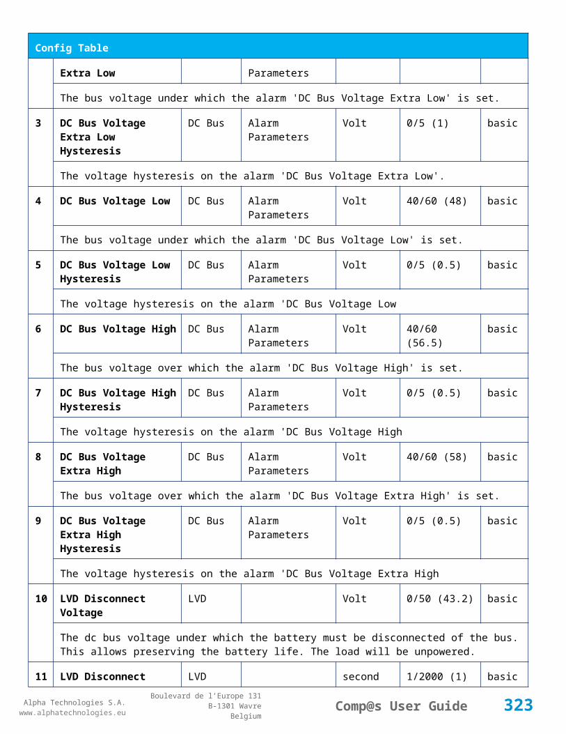
Alpha Technologies S.A.www.alphatechnologies.eu
Alpha Technologies S.A.www.alphatechnologies.eu
Comp@s User GuideBoulevard de l’Europe 131
B-1301 WavreBelgium
Config Table
The battery current under which the battery test must be stopped because the load is too low.
75 Battery Test Time Out Battery Battery Test minute 1/5000 (10) battery
The timeout in minute after which the battery test must be stopped.
76 Battery Test Requested Minutes Without Mains Failure
Battery Battery Test minute 0/5000 (1440) battery
The minimal time in minute without mains failure in order to allow a battery start. This parameter is not taken into account when the battery test is forced.
77 Battery Test Scheduler Cron Rule
Battery Battery Test basic
83 Smart Energy Boolean Condition
Smart Energy
asset
This is the boolean condition which allows or not to automatically optimize the number of rectifier in remote off.
86 Battery LVD Node Id LVD True/False (False)
basic
This is a list of the node id of the Smart Electronic LVDs, coma separated
91 Digital Input 1 Name Digital Inputs
Digital Input 1 Distribution Breaker Open
basic
The name of the digital input 1
92 Digital Input 1 Normally Closed
Digital Inputs
Digital Input 1 True/False (True)
basic
True/False value defining if the digital input 1 is normally closed. If this digital input is not in this default state, the related alarm is set.
93 Digital Input 2 Name Digital Inputs
Digital Input 2 Battery Breaker Open
basic
The name of the digital input 2
94 Digital Input 2 Normally Closed
Digital Inputs
Digital Input 2 True/False (True)
basic
True/False value defining if the digital input 2 is normally closed. If this digital input is not in this default state, the related alarm is set.
95 Digital Input 3 Name Digital Inputs
Digital Input 3 Digital Input 3 basic
323
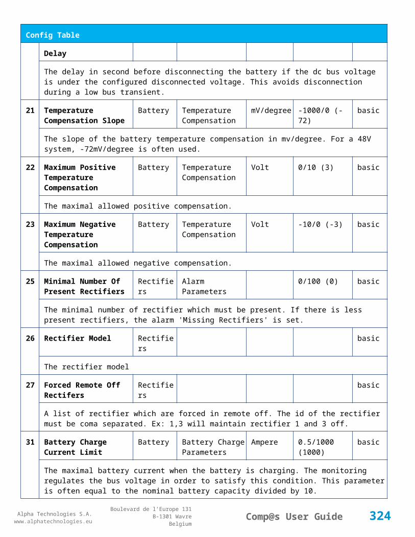
Alpha Technologies S.A.www.alphatechnologies.eu
Alpha Technologies S.A.www.alphatechnologies.eu
Comp@s User GuideBoulevard de l’Europe 131
B-1301 WavreBelgium
Config Table
The name of the digital input 3
96 Digital Input 3 Normally Closed
Digital Inputs
Digital Input 3 True/False (True)
basic
True/False value defining if the digital input 3 is normally closed. If this digital input is not in this default state, the related alarm is set.
97 Digital Input 4 Name Digital Inputs
Digital Input 4 Digital Input 4 basic
The name of the digital input 4
98 Digital Input 4 Normally Closed
Digital Inputs
Digital Input 4 True/False (True)
basic
True/False value defining if the digital input 4 is normally closed. If this digital input is not in this default state, the related alarm is set.
111
Dry Alarm 1 Alternative Boolean Condition
Relays Relay 1 plc
Another Boolean condition to activate the dry alarm relay 1. The way to define boolean condition is detailed in the PLC chapter.
112
Dry Alarm 2 Alternative Boolean Condition
Relays Relay 2 plc
Another Boolean condition to activate the dry alarm relay 2. The way to define boolean condition is detailed in the PLC chapter.
113
Dry Alarm 3 Alternative Boolean Condition
Relays Relay 3 plc
Another Boolean condition to activate the dry alarm relay 3. The way to define boolean condition is detailed in the PLC chapter.
114
Dry Alarm 4 Alternative Boolean Condition
Relays Relay 4 plc
Another Boolean condition to activate the dry alarm relay 4. The way to define boolean condition is detailed in the PLC chapter.
521
Read Access User Numbers
Generic Allowed Users (1,2,3,4,5) basic
The list of the user numbers which have read access to this equipment. The user numbers are coma separated. The accepted user id are 1,2,3,4 and 5. Ex: 1,3,4
522
Write Access User Numbers
Generic Allowed Users () basic
The list of the user numbers which have write access to this equipment. This means that these users can modify the configuration element, the alarm settings and use the control elements. The user
324

Alpha Technologies S.A.www.alphatechnologies.eu
Alpha Technologies S.A.www.alphatechnologies.eu
Comp@s User GuideBoulevard de l’Europe 131
B-1301 WavreBelgium
Config Table
numbers are coma separated. The accepted user ids are 1,2,3,4 and 5. Ex: 1,3,4
601
Event Table Length Generic Events 10/4000 (100) basic
The maximum length of the table. The value must be comprised between 10 and 4000
602
Event Table Length By Rectifier
Generic Events 10/4000 (100) basic
The maximum length of the table. The value must be comprised between 10 and 4000
901
Number Of PLC Data PLC (0) plc
The number of PLC data. Every equipment can manage up to 20 user programmable data. Data elements are automatically added in the data table. Configuration parameters are added to set the PLC Data Name and the PLC Data Mathematical calculation. In order to use these functionalities, you need a license with the 'PLC' module
902
Number Of PLC Alarm PLC (0) plc
The number of PLC alarm. Every equipment can manage up to 20 user programmable alarms. Alarm elements are automatically added in the alarm table. The alarm parameters are added to set the PLC Alarm Name and the PLC Alarm Boolean condition. In order to use these functionalities, you need a licence with the 'PLC' module
Control Table
Id Name Group SubGroup License
1 Back To Float System basic
The dc system must go back in floating mode.
2 Start Battery Test System battery
The dc system must start a battery test.
3 Force Battery Test System battery
The dc system must force a battery test.
4 Start Boost Mode System battery
The dc system must go in boost mode.
11 Open The LVD LVD basic
Try to open the LVD. It could not work if the LVD is electronic, and the request will be canceled after 15 sec.
12 Close The LVD LVD basic
325

Alpha Technologies S.A.www.alphatechnologies.eu
Alpha Technologies S.A.www.alphatechnologies.eu
Comp@s User GuideBoulevard de l’Europe 131
B-1301 WavreBelgium
Control Table
The LVD must be closed
21 Correct Battery Current Offset Battery basic
31 Reset Battery Current Integration Battery basic
Reset the integration of the battery current.
41 Reset Last Battery Test State Battery battery
Reset the state of the last battery test. If an alarm 'Battery Last Test Failed' is set, the alarm will be cleared.
51 Save Configuration In MCU Save basic
Save configuration parameters in the MCU microcontroller. If comp@s is not present, the system will be correctly managed.
55 Set MCU Specific Configuration Id Advanced Factory basic
This control allows to reconfigure the MCU to support specific hardware configuration, with embedded distribution for example
61 Set Digital Input 4 Counter Value Digital Inputs Digital Input 4 basic
Set Counter Value
111
Invert Relay 1 State For X Seconds Relays Relay 1 basic
Generate Pulse on relay 1
112
Invert Relay 2 State For X Seconds Relays Relay 2 basic
Generate Pulse on relay 2
113
Invert Relay 3 State For X Seconds Relays Relay 3 basic
Generate Pulse on relay 3
114
Invert Relay 4 State For X Seconds Relays Relay 4 basic
Generate Pulse on relay 4
501
Clear My Events Generic Events basic
By writing '1' to this control element, all the events of this equipment will be cleared.
502
Clear All Events Generic Events basic
By writing '1' to this control element, all the events of this equipment and all the events of all the sub-equipments will be cleared.
326
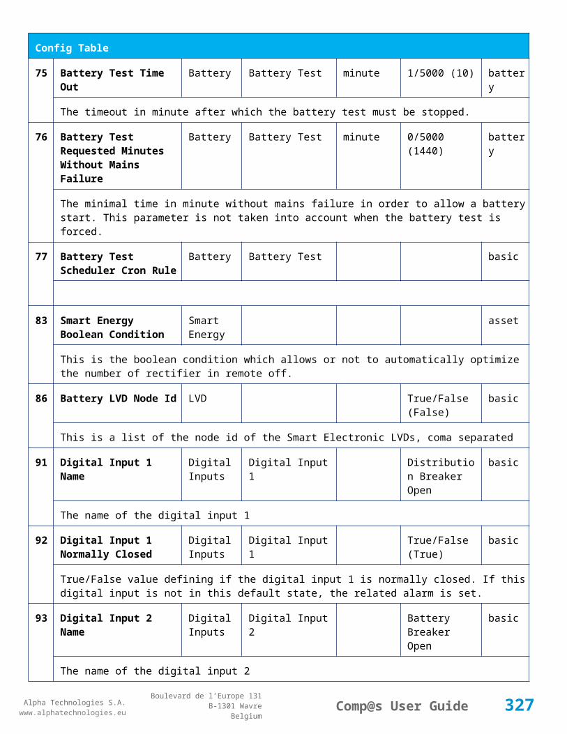
Alpha Technologies S.A.www.alphatechnologies.eu
Alpha Technologies S.A.www.alphatechnologies.eu
Comp@s User GuideBoulevard de l’Europe 131
B-1301 WavreBelgium
Control Table
511
Add Event Generic Events basic
This control element adds an event of severity none. The event name is the text written to this control element
512
Add Major Event Generic Events basic
This control element adds an event of severity major. The event name is the text written to this control element
521
Reset Default Names And Groups Generic Renaming basic
This control element resets all the element Names, Groups and Subgroups to default values for this equipment
522
Reset Default Names And Groups Recursive Generic Renaming basic
This control element resets all the element Names, Groups and Subgroups to default values for this equipment and all sub equipments
7.2.13 MCU1848M6
Device Information
Name MCU1848M6
Short Description Controller without LCD display
Long Description Monitoring and control unit with USB and Ethernet port - ACE186 line
Hardware Reference 9413 061 85001
Software Reference SOFT 000033 XX
Equipment Type Monitoring Control Unit
ETSI Level /site/energy_system/dc_system
Description Table
Id Name Group SubGroup License
1 Description Description Custom Description basic
A free text zone to write a system description
2 Reference Description Custom Description basic
A free text zone to write the customer reference of the system
11 Product Name Description Product Info basic
327
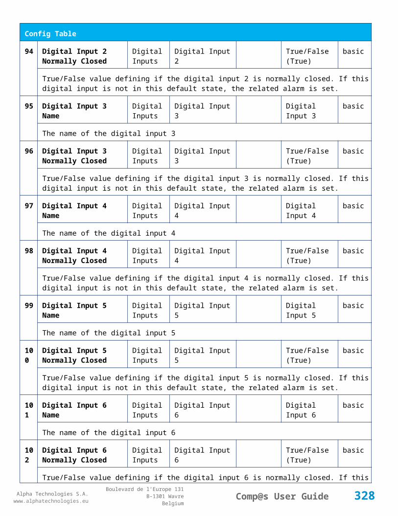
Alpha Technologies S.A.www.alphatechnologies.eu
Alpha Technologies S.A.www.alphatechnologies.eu
Comp@s User GuideBoulevard de l’Europe 131
B-1301 WavreBelgium
Description Table
The product name of the DC system monitoring
12 Hardware Reference Description Product Info basic
The hardware reference of the DC system monitoring
14 Software Reference Description Product Info asset
The serial number of the DC system monitoring
16 Serial Number Description Product Info asset
The serial number of the DC system monitoring
18 Manufacturing Date Description Product Info asset
The production date of the DC system monitoring
Alarm Table
Id Name Group SubGroup Severity Type (Level)
Set/Clear Delay
1 DC Bus Extra Low DC Bus major (6) 5 / 2
The bus voltage is extra low. The alarm is set when the bus voltage is lower than the configuration parameter 'DC Bus Voltage Extra Low'. There is an hysteresis on the alarm : 'DC Bus Voltage Extra Low Hysteresis'. The alarm is not activated when DC mode is BATTERY TEST
2 DC Bus Low DC Bus minor (4) 5 / 2
The bus voltage is low. The alarm is set when the bus voltage is lower than the configuration parameter 'DC Bus Voltage Low'. There is an hysteresis on the alarm : 'DC Bus Voltage Low Hysteresis'
3 DC Bus High DC Bus minor (4) 5 / 2
The bus voltage is high. The alarm is set when the bus voltage is higher than the configuration paramenter 'DC Bus Voltage High'. There is an hysterisis on the alarm : 'DC Bus Voltage High Hysteresis'
4 DC Bus Extra High DC Bus major (6) 5 / 2
The bus voltage is extra high. The alarm is set when the bus voltage is higher than the configuration paramenter 'DC Bus Voltage Extra High'. There is an hysterisis on the alarm : 'DC Bus Voltage Extra High Hysteresis'
5 DC Bus Voltage Sense Failure
DC Bus major (6) 5 / 2
The DC bus voltage sense is defective. The DC bus voltage is unconnected or unconfigured.
328

Alpha Technologies S.A.www.alphatechnologies.eu
Alpha Technologies S.A.www.alphatechnologies.eu
Comp@s User GuideBoulevard de l’Europe 131
B-1301 WavreBelgium
Alarm Table
6 Mains Failure AC Bus minor (4) 5 / 2
The number of active rectifiers is equal to 0 and the number of rectifiers in AC failure is greater than 0.
7 Mains Partial Failure AC Bus minor (4) 10 / 2
The number of active rectifiers is greater than 0 and the number of rectifiers in AC failure is greater than 0. Some rectifiers are in AC Failure. It may be caused by an open breaker, a real phase failure, or by a rectifier failure.
8 Mains Low AC Bus warning (2) 10 / 2
The main voltage is low on one or more phases. No rectifier is in AC failure. If MCU master type is 30110, 3096 or 3048M6, an hysteresis _phase123Hysteresis is added to the voltage lower limit
10
One Rectifier Failure Rectifiers minor (4) 5 / 2
One rectifier must be replaced or is not powered correctly. The DC fail alarm of the rectifier is set. The number of rectifier with DC Failure is higher than 0, there is no mains failure, and the 'More Than One Rectifier Failure alarm is not set.'
11
More Than One Rectifier Failure
Rectifiers major (6) 10 / 2
There is no mains failure and number of rectifier failures is greater than 1.
12
Missing Rectifiers Rectifiers major (6) 5 / 2
There is not enough rectifier according to the configuration parameter : 'Minimal Number Of Rectifier'
13
Battery Last Test Failed Battery Battery Test minor (3) 5 / 2
The last battery test did not succeed and was not cancelled. Maybe the battery should be replaced.
14
Battery On Discharge Battery minor (4) 10 / 2
The battery is discharging. This means that the load is too high for the installed rectifiers. This alarm is inactive when the system in AC Failure or during a battery test. There is an hysteresis corresponding to battery parameter 'Is discharging current hysteresis'.
17
Battery LVD Relay Open LVD major (6) 5 / 2
The battery Low Voltage Disconnector is open. On Systems without LVD_Status signal, like MCU 1848 or MCU 1x6, the alarm is present only if the signal LVD_COM asks to open the LVD
18
Battery Temperature Too High
Battery Temperature minor (3) 5 / 2
The temperature of the battery is too high and is greater than -600 units. There is an hysteresis corresponding to battery parameter 'Temperature hysteresis'.
19
Battery Temperature Too Low
Battery Temperature minor (3) 5 / 2
329

Alpha Technologies S.A.www.alphatechnologies.eu
Alpha Technologies S.A.www.alphatechnologies.eu
Comp@s User GuideBoulevard de l’Europe 131
B-1301 WavreBelgium
Alarm Table
The temperature of the battery is too low and is greater than -600 units. There is an hysteresis corresponding to battery parameter 'Temperature hysteresis'.
20
Battery Temperature Sensor Fail
Battery Temperature minor (3) 5 / 2
The battery temperature sensor (NTC) value is inferior to -500 units meaning that it is not connected or defective.
21
Ambient Temperature Too High
Sensors Temperature minor (0) 5 / 2
The ambient temperature is too high and is greater than -600 units. There is an hysteresis corresponding to parameter 'Ambiant temperature hysteresis'. This alarm is only activated on MCU master types 30110, 3096, 30125, 0024, 0948, 0548, 0348, 0948 and 3048M6.
22
Ambient Temperature Too Low
Sensors Temperature minor (0) 5 / 2
The ambient temperature is too low and is greater than -600 units. There is an hysteresis corresponding to parameter 'Ambiant temperature hysteresis'. This alarm is only activated on MCU master types 30110, 3096, 30125, 0024, 0948, 0548, 0348, 0948 and 3048M6.
23
Ambient Temperature Sensor Fail
Sensors Temperature minor (0) 5 / 2
The ambiant temperature sensor (NTC) value is inferior to -500 units meaning that it is not connected or defective.
25
Distribution Breaker Open Digital Inputs major (6) 5 / 2
This alarm is related to digital input 1. This alarm is activated if digital input value is different to configuration parameter 'Digital Input Alarm Value'
26
Battery Breaker Open Digital Inputs minor (4) 5 / 2
This alarm is related to digital input 2. This alarm is activated if digital input value is different to configuration parameter 'Digital Input Alarm Value'
27
Digital Input 3 Digital Inputs none (0) 5 / 2
This alarm is related to digital input 3. This alarm is activated if digital input value is different to configuration parameter 'Digital Input Alarm Value'
28
Digital Input 4 Digital Inputs none (0) 5 / 2
This alarm is related to digital input 4. This alarm is activated if digital input value is different to configuration parameter 'Digital Input Alarm Value'
Data Table
Id Name Group SubGroup Unit License
330

Alpha Technologies S.A.www.alphatechnologies.eu
Alpha Technologies S.A.www.alphatechnologies.eu
Comp@s User GuideBoulevard de l’Europe 131
B-1301 WavreBelgium
Data Table
1 DC Mode System basic
The DC system can have 4 values: 'FLOAT', 'BOOST', 'BATTERY_TEST', 'AC_FAILURE' or SAFE
2 Previous DC Mode System basic
The previous value of the DC Mode
11 Bus Voltage DC Bus Volt basic
The DC bus voltage in volt.
12 Ratio Delivered On Available Power
System % basic
This is the ratio of the delivered power divided by the installed power, in %.
13 Minutes Since Last AC Failure Begin
AC Bus minute basic
The number of minute since the last AC Failure begin
14 Minutes Since Last AC Failure End
AC Bus minute basic
The number of minute since the last AC Failure end
21 Rectifiers Output Power Rectifiers Watt basic
The sum of the delivered rectifier power
22 Rectifiers Output Current Rectifiers Ampere basic
The sum of the delivered rectifier current
23 Rectifiers Output Power Max Rectifiers Watt basic
The sum of the deliverable rectifier power
24 Rectifiers Output Current Max Rectifiers Ampere basic
The sum of the deliverable rectifier current
31 Number Of Rectifier Max Rectifiers Numbers basic
The maximum possible number of rectifier in this dc system
32 Number Of Present Rectifier Rectifiers Numbers basic
The actual number of present rectifier in this dc system
33 Number Of Absent Rectifier Rectifiers Numbers basic
The actual number of absent rectifier in this dc system
331

Alpha Technologies S.A.www.alphatechnologies.eu
Alpha Technologies S.A.www.alphatechnologies.eu
Comp@s User GuideBoulevard de l’Europe 131
B-1301 WavreBelgium
Data Table
34 Number Of Active Rectifier Rectifiers Numbers basic
The actual number of active rectifier in this dc system. An active rectifier is a rectifier which is present, DC OK, AC OK and not in remote off.
35 Number Of AC-Fail Rectifier Rectifiers Numbers basic
The actual number or rectifier in AC Failure.
36 Number Of DC-Fail Rectifier Rectifiers Numbers basic
The actual number or rectifier with DC Failure.
37 Number Of Remote Off Rectifier Rectifiers Numbers basic
The actual number or rectifier in remote off.
38 Number Of Over Temperature Rectifier
Rectifiers Numbers basic
The actual number or rectifier in OVer Temperature.
51 Load Power Load Watt basic
Estimation of the load power consumption
52 Load Current Load Ampere basic
Estimation of the load current consumption
61 Battery Input Current Battery Ampere basic
Measurement of the battery input current. A negative value means that the battery is discharging
62 Battery Input Power Battery Watt basic
Measurement of the battery input power. A negative value means that the battery is discharging
71 Battery Temperature Battery Temperature degree C basic
The battery temperature
72 Battery Test State Battery Battery Test basic
This is about the result of the last battery test. 9 values are possible : NEVER_TESTED, SUCCESS, ON_GOING, FAILED_TIMEOUT, FAILED_VBUS_TOO_LOW, FAILED_LOAD_TOO_LOW, FAILED_AC_FAILURE, FAILED_CANCELED, FAILED_LVD_OPENED
73 Battery Test Discharged Capacity Ratio
Battery Battery Test % basic
This is the battery capacity, in percent, discharged during the last battery test. This value is updated at the end of the battery test.
332

Alpha Technologies S.A.www.alphatechnologies.eu
Alpha Technologies S.A.www.alphatechnologies.eu
Comp@s User GuideBoulevard de l’Europe 131
B-1301 WavreBelgium
Data Table
74 Battery Test Discharged Capacity
Battery Battery Test Ah basic
This is the battery capacity, in ampere hour, discharged during the last battery test. This value is updated at the end of the battery test.
75 Battery Test Final Voltage Battery Battery Test % basic
This is the bus voltage at the end of the last battery test. This value is updated at the end of the battery test.
81 Previous Battery Test State Battery Battery Test basic
The result of the previous battery test
82 Minutes Since Last Test Battery Battery Battery Test basic
The number of minute without battery test
84 Next Scheduled Battery Test Battery Battery Test basic
The date and time of the next time the scheduled battery test will run
91 Battery Charge Capacity Battery % basic
The battery charge capacity, calculated by integration of the current.
92 Calculated Autonomy Battery minute basic
Calculation of the remaining autonomy
93 Battery Current Integration Battery As basic
Actual value of the integration of the current, in Ampere * second
94 Battery Current Integration Battery Ah basic
Actual value of the integration of the current, in Ampere * hour
101
LVD State LVD basic
Actual state of the LVD
111
Relay 1 State Relays Relay 1 basic
Actual state of the Relay 1
112
Relay 2 State Relays Relay 2 basic
Actual state of the Relay 2
113
Relay 3 State Relays Relay 3 basic
Actual state of the Relay 3
333

Alpha Technologies S.A.www.alphatechnologies.eu
Alpha Technologies S.A.www.alphatechnologies.eu
Comp@s User GuideBoulevard de l’Europe 131
B-1301 WavreBelgium
Data Table
114
Relay 4 State Relays Relay 4 basic
Actual state of the Relay 3
121
Efficiency Optimized Number Of Rectifier
Smart Energy asset
The optimal number of ON rectifier for Efficiency Optimization
122
System Loss Without Optimisation
Smart Energy Watt underdev
Estimation of the losses without optimisation
123
System Loss With Optimisation Smart Energy Watt underdev
Estimation of the losses with optimisation
124
Rectifier Model Used For Calculation
Smart Energy asset
The rectifier model used
125
Smart Energy Savings Smart Energy Watt asset
Estimation of the losses with optimisation
151
Ambient Temperature Sensors Temperature degree C basic
The ambiant temperature (second temperature sense)
161
Voltage 1 Sensors Voltage 1 Volt basic
The voltage measured by the sense 1. Can be used for battery symmetry measurement. Calculation can be done with the PLC
162
Voltage 2 Sensors Voltage 2 Volt basic
The voltage measured by the sense 2. Can be used for battery symmetry measurement. Calculation can be done with the PLC
163
Voltage 3 Sensors Voltage 3 Volt basic
The voltage measured by the sense 3. Can be used for battery symmetry measurement. Calculation can be done with the PLC
204
Pulse Counter 4 Sensors Pulse Counter 4 basic
The counter value of the digital input 4.
334

Alpha Technologies S.A.www.alphatechnologies.eu
Alpha Technologies S.A.www.alphatechnologies.eu
Comp@s User GuideBoulevard de l’Europe 131
B-1301 WavreBelgium
Config Table
Id Name Group SubGroup Unit Range: Min/Max (default)
License
1 DC Bus Float Voltage at 25 degC
DC Bus Volt 40/60 (54) basic
The floating dc bus voltage of the system at 25 Celsius degree
2 DC Bus Voltage Extra Low
DC Bus Alarm Parameters Volt 40/60 (45) basic
The bus voltage under which the alarm 'DC Bus Voltage Extra Low' is set.
3 DC Bus Voltage Extra Low Hysteresis
DC Bus Alarm Parameters Volt 0/5 (1) basic
The voltage hysteresis on the alarm 'DC Bus Voltage Extra Low'.
4 DC Bus Voltage Low DC Bus Alarm Parameters Volt 40/60 (48) basic
The bus voltage under which the alarm 'DC Bus Voltage Low' is set.
5 DC Bus Voltage Low Hysteresis
DC Bus Alarm Parameters Volt 0/5 (0.5) basic
The voltage hysteresis on the alarm 'DC Bus Voltage Low
6 DC Bus Voltage High DC Bus Alarm Parameters Volt 40/60 (56.5) basic
The bus voltage over which the alarm 'DC Bus Voltage High' is set.
7 DC Bus Voltage High Hysteresis
DC Bus Alarm Parameters Volt 0/5 (0.5) basic
The voltage hysteresis on the alarm 'DC Bus Voltage High
8 DC Bus Voltage Extra High
DC Bus Alarm Parameters Volt 40/60 (58) basic
The bus voltage over which the alarm 'DC Bus Voltage Extra High' is set.
9 DC Bus Voltage Extra High Hysteresis
DC Bus Alarm Parameters Volt 0/5 (0.5) basic
The voltage hysteresis on the alarm 'DC Bus Voltage Extra High
10 LVD Disconnect Voltage LVD Volt 0/50 (43.2) basic
The dc bus voltage under which the battery must be disconnected of the bus. This allows preserving the battery life. The load will be unpowered.
11 LVD Disconnect Delay LVD second 1/2000 (1) basic
335
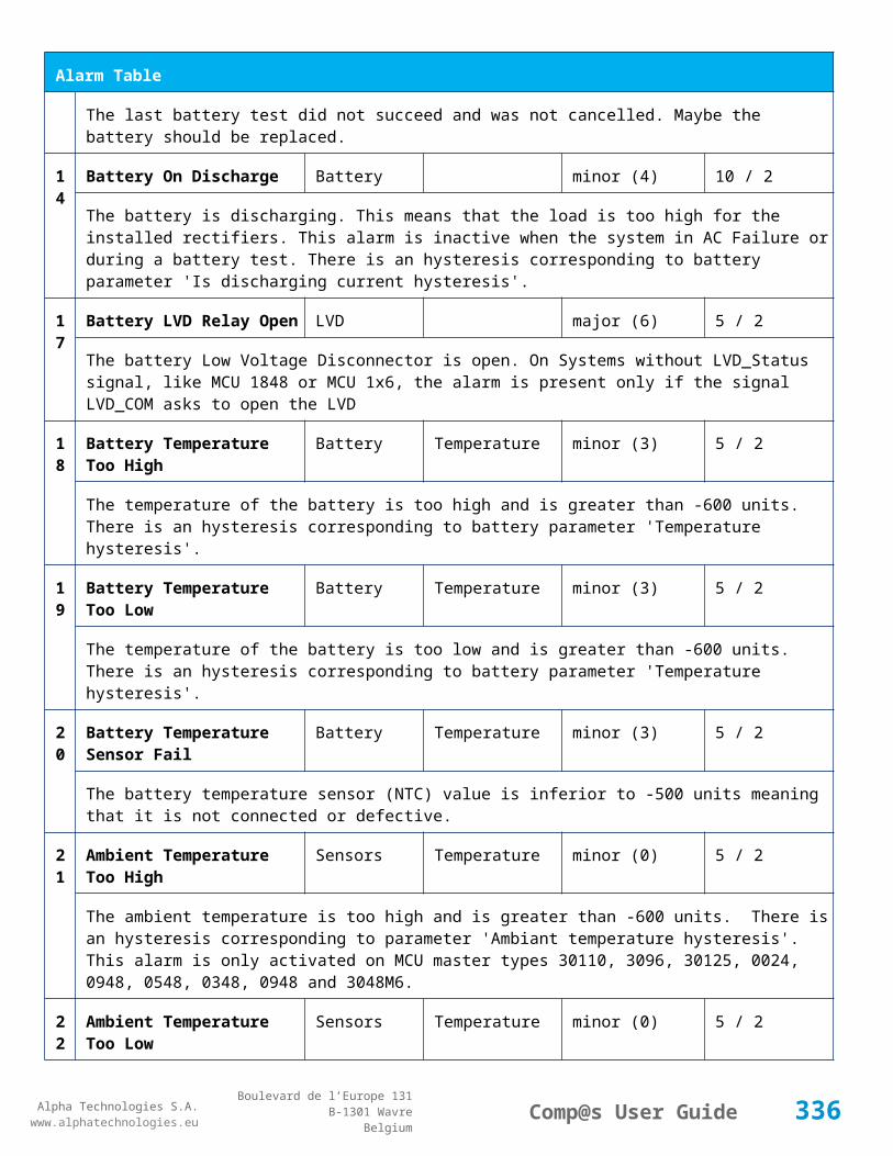
Alpha Technologies S.A.www.alphatechnologies.eu
Alpha Technologies S.A.www.alphatechnologies.eu
Comp@s User GuideBoulevard de l’Europe 131
B-1301 WavreBelgium
Config Table
The delay in second before disconnecting the battery if the dc bus voltage is under the configured disconnected voltage. This avoids disconnection during a low bus transient.
21 Temperature Compensation Slope
Battery Temperature Compensation
mV/degree -1000/0 (-72) basic
The slope of the battery temperature compensation in mv/degree. For a 48V system, -72mV/degree is often used.
22 Maximum Positive Temperature Compensation
Battery Temperature Compensation
Volt 0/10 (3) basic
The maximal allowed positive compensation.
23 Maximum Negative Temperature Compensation
Battery Temperature Compensation
Volt -10/0 (-3) basic
The maximal allowed negative compensation.
25 Minimal Number Of Present Rectifiers
Rectifiers Alarm Parameters 0/100 (0) basic
The minimal number of rectifier which must be present. If there is less present rectifiers, the alarm 'Missing Rectifiers' is set.
26 Rectifier Model Rectifiers basic
The rectifier model
27 Forced Remote Off Rectifers
Rectifiers basic
A list of rectifier which are forced in remote off. The id of the rectifier must be coma separated. Ex: 1,3 will maintain rectifier 1 and 3 off.
31 Battery Charge Current Limit
Battery Battery Charge Parameters
Ampere 0.5/1000 (1000) basic
The maximal battery current when the battery is charging. The monitoring regulates the bus voltage in order to satisfy this condition. This parameter is often equal to the nominal battery capacity divided by 10.
32 Battery String Capacity Battery Ah 3/1000 (100) basic
The battery capacity in Ah.
33 Battery Temperature Low
Battery Alarm Parameters degree C -100/20 (0) basic
The temperature under which the alarm 'Battery Temperature Too Low' must be set.
34 Battery Temperature Battery Alarm Parameters degree C 5/100 (40) basic
336

Alpha Technologies S.A.www.alphatechnologies.eu
Alpha Technologies S.A.www.alphatechnologies.eu
Comp@s User GuideBoulevard de l’Europe 131
B-1301 WavreBelgium
Config Table
High
The temperature over which the alarm 'Battery Temperature Too High' must be set.
35 Battery Temperature Hysteresis
Battery Alarm Parameters degree C 0/10 (2) basic
The hysteresis on the 'Battery Temperature Too High' and 'Battery Temperature Too Low' alarms.
36 Minimal Current For Discharging Alarm
Battery Alarm Parameters Ampere 0/1000 (3) basic
The minimal discharging current to set the 'Battery On Discharge' alarm.
37 Current Hysteresis For Discharging Alarm
Battery Alarm Parameters Ampere 0/50 (1) basic
The hysteresis on the 'Battery On Discharge' alarm.
41 Shunt Rating At 60mV Current Sensors
Shunt 1 Ampere 25/5000 (250) basic
The rating of the battery shunt at 60mV.
51 Boost Automatic Battery Boost False/False (False)
battery
The boost mode must be automatically after the fact that during a mains failure, the bus voltage went under the configured 'Boost Activation Low Voltage'. This allows charging the battery faster.
52 Boost Activation Low Voltage
Battery Boost Volt 43/50 (46) battery
The voltage under which the boost mode can be activated.
53 Boost Termination Voltage
Battery Boost Volt 50/58 (56.4) battery
The voltage over which the system must go back to floating mode.
54 Boost Termination Current
Battery Boost Ampere 0/100 (4) battery
The battery charging current under which the system must go back to floating mode.
55 Boost Termination Time Battery Boost minute 10/240 (120) battery
The time in minute after which the system must go back in floating mode.
70 Battery Test End Voltage
Battery Battery Test Volt 30/60 (46) battery
The voltage at which any battery test must be stopped.
337

Alpha Technologies S.A.www.alphatechnologies.eu
Alpha Technologies S.A.www.alphatechnologies.eu
Comp@s User GuideBoulevard de l’Europe 131
B-1301 WavreBelgium
Config Table
71 Battery Test Discharge Ratio
Battery Battery Test % 0/100 (0) battery
The ratio of the battery capacity to discharge. If 30 is set, 30% of the battery will be discharged during the test
72 Battery Test Interval Battery Battery Test day 0/3000 (0) battery
The number of days between two automatically started battery test. If this parameter is set to 0, the battery test is not started automatically. The user can remotely or locally start or force this test.
73 Battery Test Discharge Current
Battery Battery Test Ampere 3/100 (1000) battery
The current at which the battery must be discharged during a battery test. The monitoring regulates the bus voltage in order to satisfy this condition. The load current must be of course higher than this parameter.
74 Battery Test Minimal Discharge Current
Battery Battery Test Ampere 2/90 (2) battery
The battery current under which the battery test must be stopped because the load is too low.
75 Battery Test Time Out Battery Battery Test minute 1/5000 (10) battery
The timeout in minute after which the battery test must be stopped.
76 Battery Test Requested Minutes Without Mains Failure
Battery Battery Test minute 0/5000 (1440) battery
The minimal time in minute without mains failure in order to allow a battery start. This parameter is not taken into account when the battery test is forced.
77 Battery Test Scheduler Cron Rule
Battery Battery Test basic
83 Smart Energy Boolean Condition
Smart Energy
asset
This is the boolean condition which allows or not to automatically optimize the number of rectifier in remote off.
86 Battery LVD Node Id LVD True/False (False)
basic
This is a list of the node id of the Smart Electronic LVDs, coma separated
91 Digital Input 1 Name Digital Inputs
Digital Input 1 Distribution Breaker Open
basic
The name of the digital input 1
338
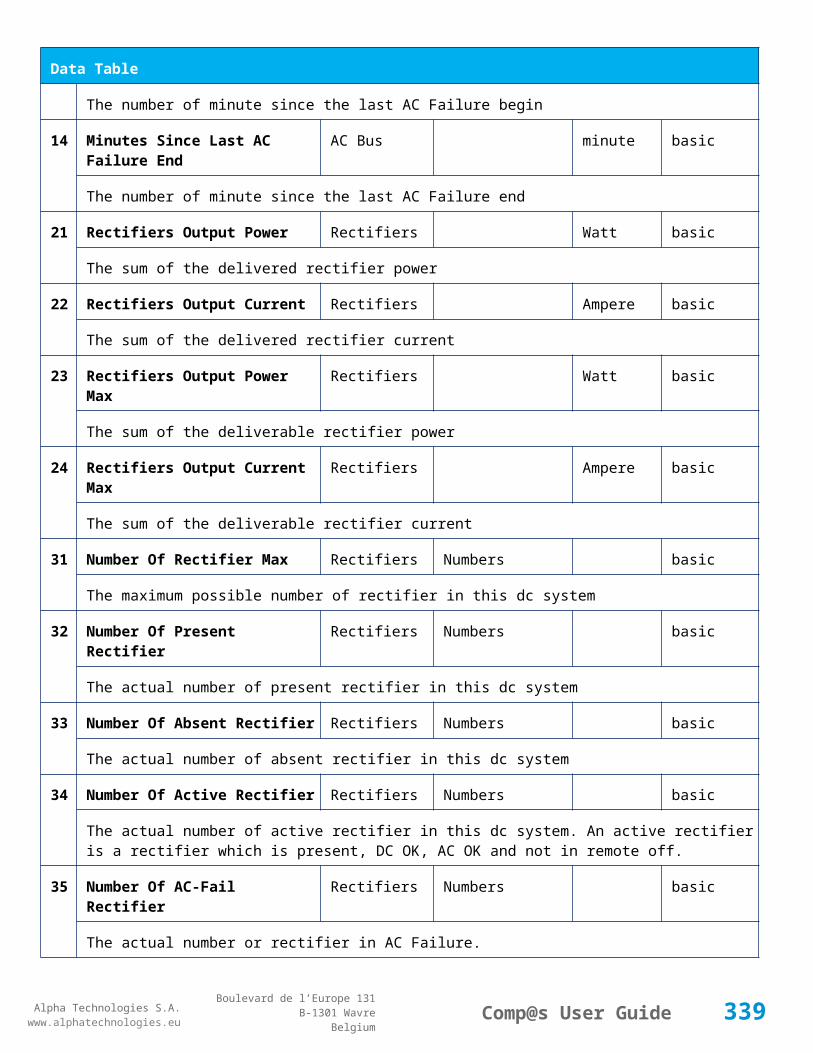
Alpha Technologies S.A.www.alphatechnologies.eu
Alpha Technologies S.A.www.alphatechnologies.eu
Comp@s User GuideBoulevard de l’Europe 131
B-1301 WavreBelgium
Config Table
92 Digital Input 1 Normally Closed
Digital Inputs
Digital Input 1 True/False (True)
basic
True/False value defining if the digital input 1 is normally closed. If this digital input is not in this default state, the related alarm is set.
93 Digital Input 2 Name Digital Inputs
Digital Input 2 Battery Breaker Open
basic
The name of the digital input 2
94 Digital Input 2 Normally Closed
Digital Inputs
Digital Input 2 True/False (True)
basic
True/False value defining if the digital input 2 is normally closed. If this digital input is not in this default state, the related alarm is set.
95 Digital Input 3 Name Digital Inputs
Digital Input 3 Digital Input 3 basic
The name of the digital input 3
96 Digital Input 3 Normally Closed
Digital Inputs
Digital Input 3 True/False (True)
basic
True/False value defining if the digital input 3 is normally closed. If this digital input is not in this default state, the related alarm is set.
97 Digital Input 4 Name Digital Inputs
Digital Input 4 Digital Input 4 basic
The name of the digital input 4
98 Digital Input 4 Normally Closed
Digital Inputs
Digital Input 4 True/False (True)
basic
True/False value defining if the digital input 4 is normally closed. If this digital input is not in this default state, the related alarm is set.
111
Dry Alarm 1 Alternative Boolean Condition
Relays Relay 1 plc
Another Boolean condition to activate the dry alarm relay 1. The way to define boolean condition is detailed in the PLC chapter.
112
Dry Alarm 2 Alternative Boolean Condition
Relays Relay 2 plc
Another Boolean condition to activate the dry alarm relay 2. The way to define boolean condition is detailed in the PLC chapter.
113
Dry Alarm 3 Alternative Boolean Condition
Relays Relay 3 plc
339

Alpha Technologies S.A.www.alphatechnologies.eu
Alpha Technologies S.A.www.alphatechnologies.eu
Comp@s User GuideBoulevard de l’Europe 131
B-1301 WavreBelgium
Config Table
Another Boolean condition to activate the dry alarm relay 3. The way to define boolean condition is detailed in the PLC chapter.
114
Dry Alarm 4 Alternative Boolean Condition
Relays Relay 4 plc
Another Boolean condition to activate the dry alarm relay 4. The way to define boolean condition is detailed in the PLC chapter.
131
Ambient Temperature Low
Sensors Temperature degree C basic
The temperature under which the alarm 'Ambiant Temperature Too Low' must be set.
132
Ambient Temperature High
Sensors Temperature degree C basic
The temperature under which the alarm 'Ambiant Temperature Too Low' must be set.
133
Ambient Temperature Hysteresis
Sensors Temperature degree C basic
The hysteresis on the 'Battery Temperature Too High' and 'Battery Temperature Too Low' alarms.
521
Read Access User Numbers
Generic Allowed Users (1,2,3,4,5) basic
The list of the user numbers which have read access to this equipment. The user numbers are coma separated. The accepted user id are 1,2,3,4 and 5. Ex: 1,3,4
522
Write Access User Numbers
Generic Allowed Users () basic
The list of the user numbers which have write access to this equipment. This means that these users can modify the configuration element, the alarm settings and use the control elements. The user numbers are coma separated. The accepted user ids are 1,2,3,4 and 5. Ex: 1,3,4
601
Event Table Length Generic Events 10/4000 (100) basic
The maximum length of the table. The value must be comprised between 10 and 4000
602
Event Table Length By Rectifier
Generic Events 10/4000 (100) basic
The maximum length of the table. The value must be comprised between 10 and 4000
901
Number Of PLC Data PLC (0) plc
The number of PLC data. Every equipment can manage up to 20 user programmable data. Data elements are automatically added in the data table. Configuration parameters are added to set the PLC Data Name and the PLC Data Mathematical calculation. In order to use these functionalities, you need a license with the 'PLC' module
90 Number Of PLC Alarm PLC (0) plc
340

Alpha Technologies S.A.www.alphatechnologies.eu
Alpha Technologies S.A.www.alphatechnologies.eu
Comp@s User GuideBoulevard de l’Europe 131
B-1301 WavreBelgium
Config Table
2 The number of PLC alarm. Every equipment can manage up to 20 user programmable alarms. Alarm elements are automatically added in the alarm table. The alarm parameters are added to set the PLC Alarm Name and the PLC Alarm Boolean condition. In order to use these functionalities, you need a licence with the 'PLC' module
Control Table
Id Name Group SubGroup License
1 Back To Float System basic
The dc system must go back in floating mode.
2 Start Battery Test System battery
The dc system must start a battery test.
3 Force Battery Test System battery
The dc system must force a battery test.
4 Start Boost Mode System battery
The dc system must go in boost mode.
11 Open The LVD LVD basic
Try to open the LVD. It could not work if the LVD is electronic, and the request will be canceled after 15 sec.
12 Close The LVD LVD basic
The LVD must be closed
21 Correct Battery Current Offset Battery basic
31 Reset Battery Current Integration Battery basic
Reset the integration of the battery current.
41 Reset Last Battery Test State Battery battery
Reset the state of the last battery test. If an alarm 'Battery Last Test Failed' is set, the alarm will be cleared.
51 Save Configuration In MCU Save basic
Save configuration parameters in the MCU microcontroller. If comp@s is not present, the system will be correctly managed.
341

Alpha Technologies S.A.www.alphatechnologies.eu
Alpha Technologies S.A.www.alphatechnologies.eu
Comp@s User GuideBoulevard de l’Europe 131
B-1301 WavreBelgium
Control Table
55 Set MCU Specific Configuration Id Advanced Factory basic
This control allows to reconfigure the MCU to support specific hardware configuration, with embedded distribution for example
61 Set Digital Input 4 Counter Value Digital Inputs Digital Input 4 basic
Set Counter Value
111
Invert Relay 1 State For X Seconds Relays Relay 1 basic
Generate Pulse on relay 1
112
Invert Relay 2 State For X Seconds Relays Relay 2 basic
Generate Pulse on relay 2
113
Invert Relay 3 State For X Seconds Relays Relay 3 basic
Generate Pulse on relay 3
114
Invert Relay 4 State For X Seconds Relays Relay 4 basic
Generate Pulse on relay 4
501
Clear My Events Generic Events basic
By writing '1' to this control element, all the events of this equipment will be cleared.
502
Clear All Events Generic Events basic
By writing '1' to this control element, all the events of this equipment and all the events of all the sub-equipments will be cleared.
511
Add Event Generic Events basic
This control element adds an event of severity none. The event name is the text written to this control element
512
Add Major Event Generic Events basic
This control element adds an event of severity major. The event name is the text written to this control element
521
Reset Default Names And Groups Generic Renaming basic
This control element resets all the element Names, Groups and Subgroups to default values for this equipment
522
Reset Default Names And Groups Recursive Generic Renaming basic
This control element resets all the element Names, Groups and Subgroups to default values for this equipment and all sub equipments
342

Alpha Technologies S.A.www.alphatechnologies.eu
Alpha Technologies S.A.www.alphatechnologies.eu
Comp@s User GuideBoulevard de l’Europe 131
B-1301 WavreBelgium
7.2.14 MCU3048M6
Device Information
Name MCU3048M6
Short Description MCU3048M6
Long Description
Hardware Reference 9413 063 05001
Software Reference SOFT 000070 XX
Equipment Type Monitoring Control Unit
ETSI Level /site/energy_system/dc_system
Description Table
Id Name Group SubGroup License
1 Description Description Custom Description basic
A free text zone to write a system description
2 Reference Description Custom Description basic
A free text zone to write the customer reference of the system
11 Product Name Description Product Info basic
The product name of the DC system monitoring
12 Hardware Reference Description Product Info basic
The hardware reference of the DC system monitoring
14 Software Reference Description Product Info asset
The serial number of the DC system monitoring
16 Serial Number Description Product Info asset
The serial number of the DC system monitoring
18 Manufacturing Date Description Product Info asset
The production date of the DC system monitoring
Alarm Table
Id Name Group SubGroup Severity Type Set/Clear Delay
343

Alpha Technologies S.A.www.alphatechnologies.eu
Alpha Technologies S.A.www.alphatechnologies.eu
Comp@s User GuideBoulevard de l’Europe 131
B-1301 WavreBelgium
Alarm Table
(Level)
1 DC Bus Extra Low DC Bus major (6) 5 / 2
The bus voltage is extra low. The alarm is set when the bus voltage is lower than the configuration parameter 'DC Bus Voltage Extra Low'. There is an hysteresis on the alarm : 'DC Bus Voltage Extra Low Hysteresis'. The alarm is not activated when DC mode is BATTERY TEST
2 DC Bus Low DC Bus minor (4) 5 / 2
The bus voltage is low. The alarm is set when the bus voltage is lower than the configuration parameter 'DC Bus Voltage Low'. There is an hysteresis on the alarm : 'DC Bus Voltage Low Hysteresis'
3 DC Bus High DC Bus minor (4) 5 / 2
The bus voltage is high. The alarm is set when the bus voltage is higher than the configuration paramenter 'DC Bus Voltage High'. There is an hysterisis on the alarm : 'DC Bus Voltage High Hysteresis'
4 DC Bus Extra High DC Bus major (6) 5 / 2
The bus voltage is extra high. The alarm is set when the bus voltage is higher than the configuration paramenter 'DC Bus Voltage Extra High'. There is an hysterisis on the alarm : 'DC Bus Voltage Extra High Hysteresis'
5 DC Bus Voltage Sense Failure
DC Bus major (6) 5 / 2
The DC bus voltage sense is defective. The DC bus voltage is unconnected or unconfigured.
6 Mains Failure AC Bus minor (4) 5 / 2
The number of active rectifiers is equal to 0 and the number of rectifiers in AC failure is greater than 0.
7 Mains Partial Failure AC Bus minor (4) 10 / 2
The number of active rectifiers is greater than 0 and the number of rectifiers in AC failure is greater than 0. Some rectifiers are in AC Failure. It may be caused by an open breaker, a real phase failure, or by a rectifier failure.
8 Mains Low AC Bus warning (2) 10 / 2
The main voltage is low on one or more phases. No rectifier is in AC failure. If MCU master type is 30110, 3096 or 3048M6, an hysteresis _phase123Hysteresis is added to the voltage lower limit
9 Mains High AC Bus warning (2) 10 / 2
The main voltage is low on one or more phases. No rectifier is in AC failure. The alarm is only active if MCU master type is 30110, 3096 or 3048M6. Therefore, an hysteresis _phase123Hysteresis is substracted to the voltage lower limit.
10
One Rectifier Failure Rectifiers minor (4) 5 / 2
One rectifier must be replaced or is not powered correctly. The DC fail alarm of the rectifier is set. The
344
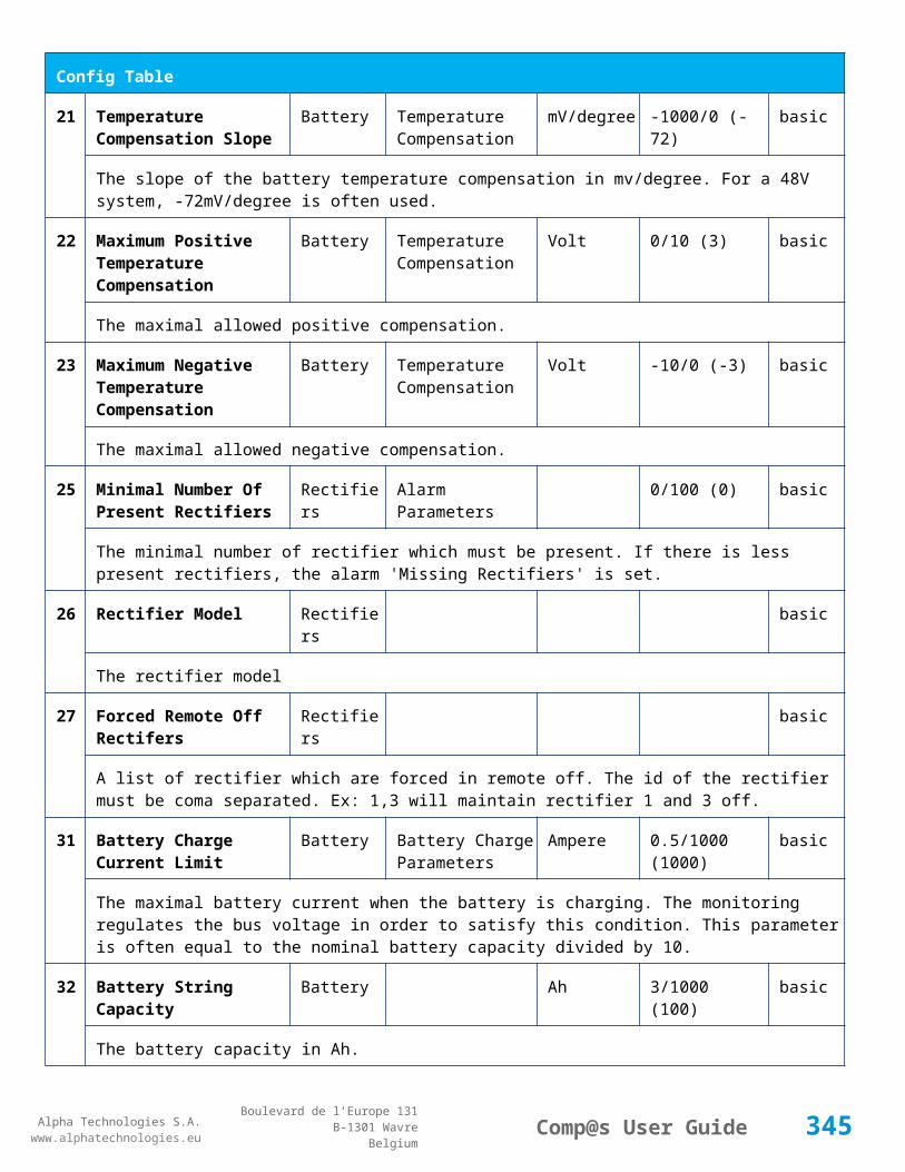
Alpha Technologies S.A.www.alphatechnologies.eu
Alpha Technologies S.A.www.alphatechnologies.eu
Comp@s User GuideBoulevard de l’Europe 131
B-1301 WavreBelgium
Alarm Table
number of rectifier with DC Failure is higher than 0, there is no mains failure, and the 'More Than One Rectifier Failure alarm is not set.'
11
More Than One Rectifier Failure
Rectifiers major (6) 10 / 2
There is no mains failure and number of rectifier failures is greater than 1.
12
Missing Rectifiers Rectifiers major (6) 5 / 2
There is not enough rectifier according to the configuration parameter : 'Minimal Number Of Rectifier'
13
Battery Last Test Failed Battery Battery Test minor (3) 5 / 2
The last battery test did not succeed and was not cancelled. Maybe the battery should be replaced.
14
Battery On Discharge Battery minor (4) 10 / 2
The battery is discharging. This means that the load is too high for the installed rectifiers. This alarm is inactive when the system in AC Failure or during a battery test. There is an hysteresis corresponding to battery parameter 'Is discharging current hysteresis'.
17
Battery LVD Relay Open LVD major (6) 5 / 2
The battery Low Voltage Disconnector is open. On Systems without LVD_Status signal, like MCU 1848 or MCU 1x6, the alarm is present only if the signal LVD_COM asks to open the LVD
18
Battery Temperature Too High
Battery Temperature minor (3) 5 / 2
The temperature of the battery is too high and is greater than -600 units. There is an hysteresis corresponding to battery parameter 'Temperature hysteresis'.
19
Battery Temperature Too Low
Battery Temperature minor (3) 5 / 2
The temperature of the battery is too low and is greater than -600 units. There is an hysteresis corresponding to battery parameter 'Temperature hysteresis'.
20
Battery Temperature Sensor Fail
Battery Temperature minor (3) 5 / 2
The battery temperature sensor (NTC) value is inferior to -500 units meaning that it is not connected or defective.
21
Ambient Temperature Too High
Sensors Temperature minor (0) 5 / 2
The ambient temperature is too high and is greater than -600 units. There is an hysteresis corresponding to parameter 'Ambiant temperature hysteresis'. This alarm is only activated on MCU master types 30110, 3096, 30125, 0024, 0948, 0548, 0348, 0948 and 3048M6.
22
Ambient Temperature Too Low
Sensors Temperature minor (0) 5 / 2
345

Alpha Technologies S.A.www.alphatechnologies.eu
Alpha Technologies S.A.www.alphatechnologies.eu
Comp@s User GuideBoulevard de l’Europe 131
B-1301 WavreBelgium
Alarm Table
The ambient temperature is too low and is greater than -600 units. There is an hysteresis corresponding to parameter 'Ambiant temperature hysteresis'. This alarm is only activated on MCU master types 30110, 3096, 30125, 0024, 0948, 0548, 0348, 0948 and 3048M6.
23
Ambient Temperature Sensor Fail
Sensors Temperature minor (0) 5 / 2
The ambiant temperature sensor (NTC) value is inferior to -500 units meaning that it is not connected or defective.
25
Distribution Breaker Open Digital Inputs major (6) 5 / 2
This alarm is related to digital input 1. This alarm is activated if digital input value is different to configuration parameter 'Digital Input Alarm Value'
26
Battery Breaker Open Digital Inputs minor (4) 5 / 2
This alarm is related to digital input 2. This alarm is activated if digital input value is different to configuration parameter 'Digital Input Alarm Value'
27
Digital Input 3 Digital Inputs none (0) 5 / 2
This alarm is related to digital input 3. This alarm is activated if digital input value is different to configuration parameter 'Digital Input Alarm Value'
28
Digital Input 4 Digital Inputs none (0) 5 / 2
This alarm is related to digital input 4. This alarm is activated if digital input value is different to configuration parameter 'Digital Input Alarm Value'
29
Digital Input 5 Digital Inputs none (0) 5 / 2
This alarm is related to digital input 5. This alarm is activated if digital input value is different to configuration parameter 'Digital Input Alarm Value'
30
Digital Input 6 Digital Inputs none (0) 5 / 2
This alarm is related to digital input 6. This alarm is activated if digital input value is different to configuration parameter 'Digital Input Alarm Value'
31
Digital Input 7 Digital Inputs none (0) 5 / 2
This alarm is related to digital input 7. This alarm is activated if digital input value is different to configuration parameter 'Digital Input Alarm Value'
32
Digital Input 8 Digital Inputs none (0) 5 / 2
This alarm is related to digital input 8. This alarm is activated if digital input value is different to configuration parameter 'Digital Input Alarm Value'
346

Alpha Technologies S.A.www.alphatechnologies.eu
Alpha Technologies S.A.www.alphatechnologies.eu
Comp@s User GuideBoulevard de l’Europe 131
B-1301 WavreBelgium
Data Table
Id Name Group SubGroup Unit License
1 DC Mode System basic
The DC system can have 4 values: 'FLOAT', 'BOOST', 'BATTERY_TEST', 'AC_FAILURE' or SAFE
2 Previous DC Mode System basic
The previous value of the DC Mode
11 Bus Voltage DC Bus Volt basic
The DC bus voltage in volt.
12 Ratio Delivered On Available Power
System % basic
This is the ratio of the delivered power divided by the installed power, in %.
13 Minutes Since Last AC Failure Begin
AC Bus minute basic
The number of minute since the last AC Failure begin
14 Minutes Since Last AC Failure End
AC Bus minute basic
The number of minute since the last AC Failure end
21 Rectifiers Output Power Rectifiers Watt basic
The sum of the delivered rectifier power
22 Rectifiers Output Current Rectifiers Ampere basic
The sum of the delivered rectifier current
23 Rectifiers Output Power Max Rectifiers Watt basic
The sum of the deliverable rectifier power
24 Rectifiers Output Current Max Rectifiers Ampere basic
The sum of the deliverable rectifier current
31 Number Of Rectifier Max Rectifiers Numbers basic
The maximum possible number of rectifier in this dc system
32 Number Of Present Rectifier Rectifiers Numbers basic
The actual number of present rectifier in this dc system
33 Number Of Absent Rectifier Rectifiers Numbers basic
347

Alpha Technologies S.A.www.alphatechnologies.eu
Alpha Technologies S.A.www.alphatechnologies.eu
Comp@s User GuideBoulevard de l’Europe 131
B-1301 WavreBelgium
Data Table
The actual number of absent rectifier in this dc system
34 Number Of Active Rectifier Rectifiers Numbers basic
The actual number of active rectifier in this dc system. An active rectifier is a rectifier which is present, DC OK, AC OK and not in remote off.
35 Number Of AC-Fail Rectifier Rectifiers Numbers basic
The actual number or rectifier in AC Failure.
36 Number Of DC-Fail Rectifier Rectifiers Numbers basic
The actual number or rectifier with DC Failure.
37 Number Of Remote Off Rectifier Rectifiers Numbers basic
The actual number or rectifier in remote off.
38 Number Of Over Temperature Rectifier
Rectifiers Numbers basic
The actual number or rectifier in OVer Temperature.
41 Mains Phase 1 Voltage AC Bus Volt basic
The voltage on AC phase 1
42 Mains Phase 2 Voltage AC Bus Volt basic
The voltage on AC phase 2
43 Mains Phase 3 Voltage AC Bus Volt basic
The voltage on AC phase 3
51 Load Power Load Watt basic
Estimation of the load power consumption
52 Load Current Load Ampere basic
Estimation of the load current consumption
61 Battery Input Current Battery Ampere basic
Measurement of the battery input current. A negative value means that the battery is discharging
62 Battery Input Power Battery Watt basic
Measurement of the battery input power. A negative value means that the battery is discharging
63 Battery String 1 Input Current Battery Ampere basic
348

Alpha Technologies S.A.www.alphatechnologies.eu
Alpha Technologies S.A.www.alphatechnologies.eu
Comp@s User GuideBoulevard de l’Europe 131
B-1301 WavreBelgium
Data Table
Measurement of the battery 1 input current. A negative value means that the battery is discharging
64 Battery String 2 Input Current Battery Ampere basic
Measurement of the battery 2 input current. A negative value means that the battery is discharging
65 Battery String 3 Input Current Battery Ampere basic
Measurement of the battery 3 input current. A negative value means that the battery is discharging
67 Voltage Offset For Shunt regulation
Battery Volt basic
71 Battery Temperature Battery Temperature degree C basic
The battery temperature
72 Battery Test State Battery Battery Test basic
This is about the result of the last battery test. 9 values are possible : NEVER_TESTED, SUCCESS, ON_GOING, FAILED_TIMEOUT, FAILED_VBUS_TOO_LOW, FAILED_LOAD_TOO_LOW, FAILED_AC_FAILURE, FAILED_CANCELED, FAILED_LVD_OPENED
73 Battery Test Discharged Capacity Ratio
Battery Battery Test % basic
This is the battery capacity, in percent, discharged during the last battery test. This value is updated at the end of the battery test.
74 Battery Test Discharged Capacity
Battery Battery Test Ah basic
This is the battery capacity, in ampere hour, discharged during the last battery test. This value is updated at the end of the battery test.
75 Battery Test Final Voltage Battery Battery Test % basic
This is the bus voltage at the end of the last battery test. This value is updated at the end of the battery test.
81 Previous Battery Test State Battery Battery Test basic
The result of the previous battery test
82 Minutes Since Last Test Battery Battery Battery Test basic
The number of minute without battery test
84 Next Scheduled Battery Test Battery Battery Test basic
The date and time of the next time the scheduled battery test will run
349
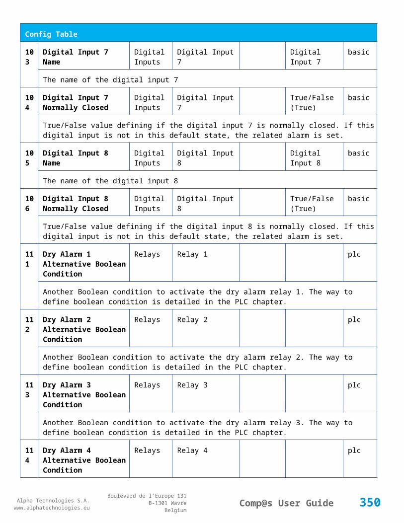
Alpha Technologies S.A.www.alphatechnologies.eu
Alpha Technologies S.A.www.alphatechnologies.eu
Comp@s User GuideBoulevard de l’Europe 131
B-1301 WavreBelgium
Data Table
91 Battery Charge Capacity Battery % basic
The battery charge capacity, calculated by integration of the current.
92 Calculated Autonomy Battery minute basic
Calculation of the remaining autonomy
93 Battery Current Integration Battery As basic
Actual value of the integration of the current, in Ampere * second
94 Battery Current Integration Battery Ah basic
Actual value of the integration of the current, in Ampere * hour
101
LVD State LVD basic
Actual state of the LVD
111
Relay 1 State Relays Relay 1 basic
Actual state of the Relay 1
112
Relay 2 State Relays Relay 2 basic
Actual state of the Relay 2
113
Relay 3 State Relays Relay 3 basic
Actual state of the Relay 3
114
Relay 4 State Relays Relay 4 basic
Actual state of the Relay 3
121
Efficiency Optimized Number Of Rectifier
Smart Energy asset
The optimal number of ON rectifier for Efficiency Optimization
122
System Loss Without Optimisation
Smart Energy Watt underdev
Estimation of the losses without optimisation
123
System Loss With Optimisation Smart Energy Watt underdev
Estimation of the losses with optimisation
124
Rectifier Model Used For Calculation
Smart Energy asset
The rectifier model used
350
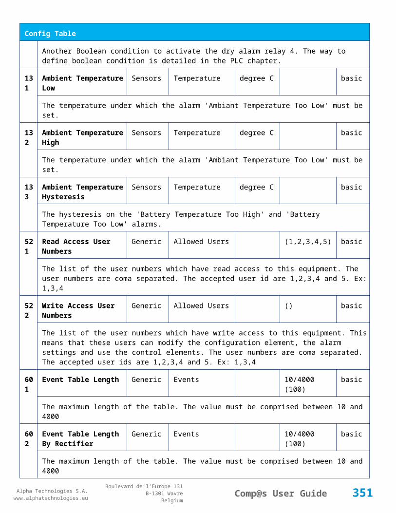
Alpha Technologies S.A.www.alphatechnologies.eu
Alpha Technologies S.A.www.alphatechnologies.eu
Comp@s User GuideBoulevard de l’Europe 131
B-1301 WavreBelgium
Data Table
125
Smart Energy Savings Smart Energy Watt asset
Estimation of the losses with optimisation
151
Ambient Temperature Sensors Temperature degree C basic
The ambiant temperature (second temperature sense)
161
Voltage 1 Sensors Voltage 1 Volt basic
The voltage measured by the sense 1. Can be used for battery symmetry measurement. Calculation can be done with the PLC
162
Voltage 2 Sensors Voltage 2 Volt basic
The voltage measured by the sense 2. Can be used for battery symmetry measurement. Calculation can be done with the PLC
163
Voltage 3 Sensors Voltage 3 Volt basic
The voltage measured by the sense 3. Can be used for battery symmetry measurement. Calculation can be done with the PLC
204
Pulse Counter 4 Sensors Pulse Counter 4 basic
The counter value of the digital input 4.
Config Table
Id Name Group SubGroup Unit Range: Min/Max (default)
License
1 DC Bus Float Voltage at 25 degC
DC Bus Volt 40/60 (54) basic
The floating dc bus voltage of the system at 25 Celsius degree
2 DC Bus Voltage Extra Low
DC Bus Alarm Parameters Volt 40/60 (45) basic
The bus voltage under which the alarm 'DC Bus Voltage Extra Low' is set.
3 DC Bus Voltage Extra Low Hysteresis
DC Bus Alarm Parameters Volt 0/5 (1) basic
The voltage hysteresis on the alarm 'DC Bus Voltage Extra Low'.
4 DC Bus Voltage Low DC Bus Alarm Parameters Volt 40/60 (48) basic
The bus voltage under which the alarm 'DC Bus Voltage Low' is set.
351

Alpha Technologies S.A.www.alphatechnologies.eu
Alpha Technologies S.A.www.alphatechnologies.eu
Comp@s User GuideBoulevard de l’Europe 131
B-1301 WavreBelgium
Config Table
5 DC Bus Voltage Low Hysteresis
DC Bus Alarm Parameters Volt 0/5 (0.5) basic
The voltage hysteresis on the alarm 'DC Bus Voltage Low
6 DC Bus Voltage High DC Bus Alarm Parameters Volt 40/60 (56.5) basic
The bus voltage over which the alarm 'DC Bus Voltage High' is set.
7 DC Bus Voltage High Hysteresis
DC Bus Alarm Parameters Volt 0/5 (0.5) basic
The voltage hysteresis on the alarm 'DC Bus Voltage High
8 DC Bus Voltage Extra High
DC Bus Alarm Parameters Volt 40/60 (58) basic
The bus voltage over which the alarm 'DC Bus Voltage Extra High' is set.
9 DC Bus Voltage Extra High Hysteresis
DC Bus Alarm Parameters Volt 0/5 (0.5) basic
The voltage hysteresis on the alarm 'DC Bus Voltage Extra High
10 LVD Disconnect Voltage LVD Volt 0/50 (43.2) basic
The dc bus voltage under which the battery must be disconnected of the bus. This allows preserving the battery life. The load will be unpowered.
11 LVD Disconnect Delay LVD second 1/2000 (1) basic
The delay in second before disconnecting the battery if the dc bus voltage is under the configured disconnected voltage. This avoids disconnection during a low bus transient.
21 Temperature Compensation Slope
Battery Temperature Compensation
mV/degree -1000/0 (-72) basic
The slope of the battery temperature compensation in mv/degree. For a 48V system, -72mV/degree is often used.
22 Maximum Positive Temperature Compensation
Battery Temperature Compensation
Volt 0/10 (3) basic
The maximal allowed positive compensation.
23 Maximum Negative Temperature Compensation
Battery Temperature Compensation
Volt -10/0 (-3) basic
The maximal allowed negative compensation.
25 Minimal Number Of Present Rectifiers
Rectifiers Alarm Parameters 0/100 (0) basic
352
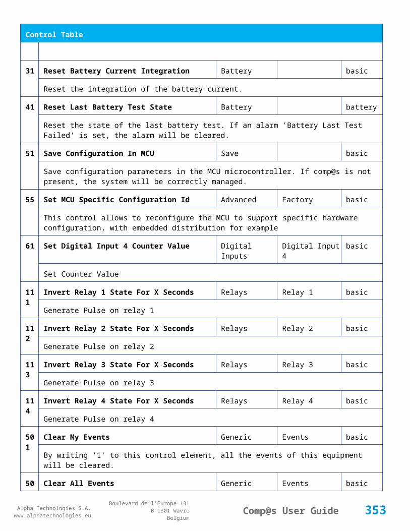
Alpha Technologies S.A.www.alphatechnologies.eu
Alpha Technologies S.A.www.alphatechnologies.eu
Comp@s User GuideBoulevard de l’Europe 131
B-1301 WavreBelgium
Config Table
The minimal number of rectifier which must be present. If there is less present rectifiers, the alarm 'Missing Rectifiers' is set.
26 Rectifier Model Rectifiers basic
The rectifier model
27 Forced Remote Off Rectifers
Rectifiers basic
A list of rectifier which are forced in remote off. The id of the rectifier must be coma separated. Ex: 1,3 will maintain rectifier 1 and 3 off.
28 Rectifier CAN Node IDs Range
Rectifiers basic
29 Rectifier Ids Declared Rectifiers basic
31 Battery Charge Current Limit
Battery Battery Charge Parameters
Ampere 0.5/3250 (1000) basic
The maximal battery current when the battery is charging. The monitoring regulates the bus voltage in order to satisfy this condition. This parameter is often equal to the nominal battery capacity divided by 10.
32 Battery String Capacity Battery Ah 3/6500 (100) basic
The battery capacity in Ah.
33 Battery Temperature Low
Battery Alarm Parameters degree C -100/20 (0) basic
The temperature under which the alarm 'Battery Temperature Too Low' must be set.
34 Battery Temperature High
Battery Alarm Parameters degree C 5/100 (40) basic
The temperature over which the alarm 'Battery Temperature Too High' must be set.
35 Battery Temperature Hysteresis
Battery Alarm Parameters degree C 0/10 (2) basic
The hysteresis on the 'Battery Temperature Too High' and 'Battery Temperature Too Low' alarms.
36 Minimal Current For Discharging Alarm
Battery Alarm Parameters Ampere 0/5000 (3) basic
The minimal discharging current to set the 'Battery On Discharge' alarm.
37 Current Hysteresis For Battery Alarm Parameters Ampere 0/500 (1) basic
353
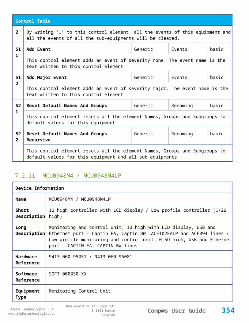
Alpha Technologies S.A.www.alphatechnologies.eu
Alpha Technologies S.A.www.alphatechnologies.eu
Comp@s User GuideBoulevard de l’Europe 131
B-1301 WavreBelgium
Config Table
Discharging Alarm
The hysteresis on the 'Battery On Discharge' alarm.
40 Number of Battery String
Battery 1-3 basic
The Number of Battery String in the system
41 Shunt Rating At 60mV Current Sensors
Shunt 1 Ampere 25/5000 (250) basic
The rating of the battery shunt at 60mV.
42 Battery 2 Charge Current Limit
Battery Ampere 0.5/3250 (1000) basic
The maximal battery current when the battery is charging. The monitoring regulates the bus voltage in order to satisfy this condition. This parameter is often equal to the nominal battery capacity divided by 10.
43 Battery 2 String Capacity
Battery Ah 3/6500 (100) basic
The battery capacity in Ah.
44 Shunt Rating At 60mV Battery Ampere 25/5000 (250) basic
The rating of the battery shunt at 60mV.
45 Battery 3 Charge Current Limit
Battery Ampere 0.5/3250 (1000) basic
The maximal battery current when the battery is charging. The monitoring regulates the bus voltage in order to satisfy this condition. This parameter is often equal to the nominal battery capacity divided by 10.
46 Battery 3 String Capacity
Battery Ah 3/6500 (100) basic
The battery capacity in Ah.
47 Shunt Rating At 60mV Battery Ampere 25/5000 (250) basic
The rating of the battery shunt at 60mV.
51 Boost Automatic Battery Boost False/False (False)
battery
The boost mode must be automatically after the fact that during a mains failure, the bus voltage went under the configured 'Boost Activation Low Voltage'. This allows charging the battery faster.
52 Boost Activation Low Voltage
Battery Boost Volt 43/50 (46) battery
354
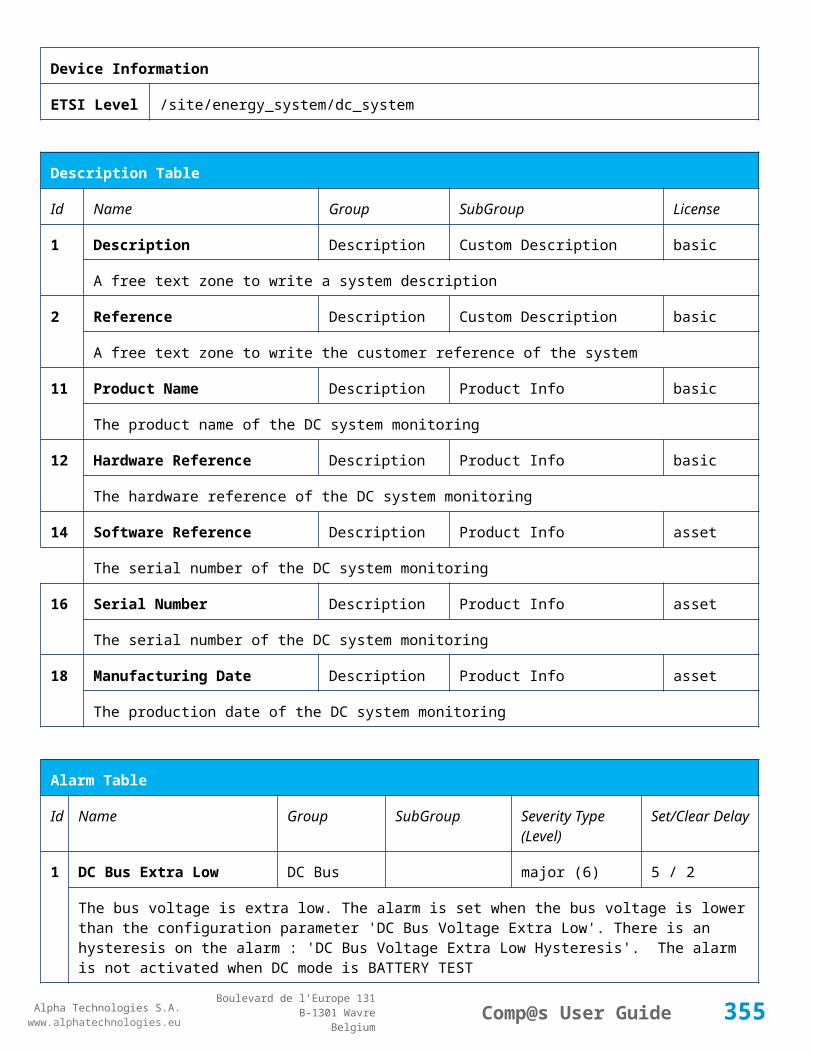
Alpha Technologies S.A.www.alphatechnologies.eu
Alpha Technologies S.A.www.alphatechnologies.eu
Comp@s User GuideBoulevard de l’Europe 131
B-1301 WavreBelgium
Config Table
The voltage under which the boost mode can be activated.
53 Boost Termination Voltage
Battery Boost Volt 50/58 (56.4) battery
The voltage over which the system must go back to floating mode.
54 Boost Termination Current
Battery Boost Ampere 0/100 (4) battery
The battery charging current under which the system must go back to floating mode.
55 Boost Termination Time Battery Boost minute 10/240 (120) battery
The time in minute after which the system must go back in floating mode.
70 Battery Test End Voltage
Battery Battery Test Volt 30/60 (46) battery
The voltage at which any battery test must be stopped.
71 Battery Test Discharge Ratio
Battery Battery Test % 0/100 (0) battery
The ratio of the battery capacity to discharge. If 30 is set, 30% of the battery will be discharged during the test
72 Battery Test Interval Battery Battery Test day 0/3000 (0) battery
The number of days between two automatically started battery test. If this parameter is set to 0, the battery test is not started automatically. The user can remotely or locally start or force this test.
73 Battery Test Discharge Current
Battery Battery Test Ampere 3/5000 (1000) battery
The current at which the battery must be discharged during a battery test. The monitoring regulates the bus voltage in order to satisfy this condition. The load current must be of course higher than this parameter.
74 Battery Test Minimal Discharge Current
Battery Battery Test Ampere 2/90 (2) battery
The battery current under which the battery test must be stopped because the load is too low.
75 Battery Test Time Out Battery Battery Test minute 1/5000 (10) battery
The timeout in minute after which the battery test must be stopped.
76 Battery Test Requested Minutes Without Mains Failure
Battery Battery Test minute 0/5000 (1440) battery
The minimal time in minute without mains failure in order to allow a battery start. This parameter is not taken into account when the battery test is forced.
355

Alpha Technologies S.A.www.alphatechnologies.eu
Alpha Technologies S.A.www.alphatechnologies.eu
Comp@s User GuideBoulevard de l’Europe 131
B-1301 WavreBelgium
Config Table
77 Battery Test Scheduler Cron Rule
Battery Battery Test basic
83 Smart Energy Boolean Condition
Smart Energy
asset
This is the boolean condition which allows or not to automatically optimize the number of rectifier in remote off.
86 Battery LVD Node Id LVD True/False (False)
basic
This is a list of the node id of the Smart Electronic LVDs, coma separated
91 Digital Input 1 Name Digital Inputs
Digital Input 1 Distribution Breaker Open
basic
The name of the digital input 1
92 Digital Input 1 Normally Closed
Digital Inputs
Digital Input 1 True/False (True)
basic
True/False value defining if the digital input 1 is normally closed. If this digital input is not in this default state, the related alarm is set.
93 Digital Input 2 Name Digital Inputs
Digital Input 2 Battery Breaker Open
basic
The name of the digital input 2
94 Digital Input 2 Normally Closed
Digital Inputs
Digital Input 2 True/False (True)
basic
True/False value defining if the digital input 2 is normally closed. If this digital input is not in this default state, the related alarm is set.
95 Digital Input 3 Name Digital Inputs
Digital Input 3 Digital Input 3 basic
The name of the digital input 3
96 Digital Input 3 Normally Closed
Digital Inputs
Digital Input 3 True/False (True)
basic
True/False value defining if the digital input 3 is normally closed. If this digital input is not in this default state, the related alarm is set.
97 Digital Input 4 Name Digital Inputs
Digital Input 4 Digital Input 4 basic
The name of the digital input 4
356

Alpha Technologies S.A.www.alphatechnologies.eu
Alpha Technologies S.A.www.alphatechnologies.eu
Comp@s User GuideBoulevard de l’Europe 131
B-1301 WavreBelgium
Config Table
98 Digital Input 4 Normally Closed
Digital Inputs
Digital Input 4 True/False (True)
basic
True/False value defining if the digital input 4 is normally closed. If this digital input is not in this default state, the related alarm is set.
99 Digital Input 5 Name Digital Inputs
Digital Input 5 Digital Input 5 basic
The name of the digital input 5
100
Digital Input 5 Normally Closed
Digital Inputs
Digital Input 5 True/False (True)
basic
True/False value defining if the digital input 5 is normally closed. If this digital input is not in this default state, the related alarm is set.
101
Digital Input 6 Name Digital Inputs
Digital Input 6 Digital Input 6 basic
The name of the digital input 6
102
Digital Input 6 Normally Closed
Digital Inputs
Digital Input 6 True/False (True)
basic
True/False value defining if the digital input 6 is normally closed. If this digital input is not in this default state, the related alarm is set.
103
Digital Input 7 Name Digital Inputs
Digital Input 7 Digital Input 7 basic
The name of the digital input 7
104
Digital Input 7 Normally Closed
Digital Inputs
Digital Input 7 True/False (True)
basic
True/False value defining if the digital input 7 is normally closed. If this digital input is not in this default state, the related alarm is set.
105
Digital Input 8 Name Digital Inputs
Digital Input 8 Digital Input 8 basic
The name of the digital input 8
106
Digital Input 8 Normally Closed
Digital Inputs
Digital Input 8 True/False (True)
basic
True/False value defining if the digital input 8 is normally closed. If this digital input is not in this default state, the related alarm is set.
111
Dry Alarm 1 Alternative Boolean Condition
Relays Relay 1 plc
Another Boolean condition to activate the dry alarm relay 1. The way to define boolean condition is
357

Alpha Technologies S.A.www.alphatechnologies.eu
Alpha Technologies S.A.www.alphatechnologies.eu
Comp@s User GuideBoulevard de l’Europe 131
B-1301 WavreBelgium
Config Table
detailed in the PLC chapter.
112
Dry Alarm 2 Alternative Boolean Condition
Relays Relay 2 plc
Another Boolean condition to activate the dry alarm relay 2. The way to define boolean condition is detailed in the PLC chapter.
113
Dry Alarm 3 Alternative Boolean Condition
Relays Relay 3 plc
Another Boolean condition to activate the dry alarm relay 3. The way to define boolean condition is detailed in the PLC chapter.
114
Dry Alarm 4 Alternative Boolean Condition
Relays Relay 4 plc
Another Boolean condition to activate the dry alarm relay 4. The way to define boolean condition is detailed in the PLC chapter.
131
Ambient Temperature Low
Sensors Temperature degree C basic
The temperature under which the alarm 'Ambiant Temperature Too Low' must be set.
132
Ambient Temperature High
Sensors Temperature degree C basic
The temperature under which the alarm 'Ambiant Temperature Too Low' must be set.
133
Ambient Temperature Hysteresis
Sensors Temperature degree C basic
The hysteresis on the 'Battery Temperature Too High' and 'Battery Temperature Too Low' alarms.
141
AC Voltage Low Mains Volt 0/240 (180) basic
The AC voltage under which the alarm AC Low is set.
142
AC Voltage High Mains Volt 80/600 (250) basic
The AC voltage over which the alarm AC High is set.
143
AC Voltage Hysteresis Mains Volt 0/40 (5) basic
The AC voltage hysteresis on alarms AC High and AC Low.
144
AC Phase 1 PLC AC Bus basic
This is the mathematical expression of the calculation of AC phase 1. If empty, the rectifiers are used. The syntax for writting mathematical expression is described in the PLC chapter. The PLC data element is the result of the calculation.
14 AC Phase 2 PLC AC Bus basic
358

Alpha Technologies S.A.www.alphatechnologies.eu
Alpha Technologies S.A.www.alphatechnologies.eu
Comp@s User GuideBoulevard de l’Europe 131
B-1301 WavreBelgium
Config Table
5 This is the mathematical expression of the calculation of AC phase 2. If empty, the rectifiers are used. The syntax for writting mathematical expression is described in the PLC chapter. The PLC data element is the result of the calculation.
146
AC Phase 3 PLC AC Bus basic
This is the mathematical expression of the calculation of AC phase 3. If empty, the rectifiers are used. The syntax for writting mathematical expression is described in the PLC chapter. The PLC data element is the result of the calculation.
151
PLD Conditition PLD basic
The PLC conditon to enable the PLD command
521
Read Access User Numbers
Generic Allowed Users (1,2,3,4,5) basic
The list of the user numbers which have read access to this equipment. The user numbers are coma separated. The accepted user id are 1,2,3,4 and 5. Ex: 1,3,4
522
Write Access User Numbers
Generic Allowed Users () basic
The list of the user numbers which have write access to this equipment. This means that these users can modify the configuration element, the alarm settings and use the control elements. The user numbers are coma separated. The accepted user ids are 1,2,3,4 and 5. Ex: 1,3,4
601
Event Table Length Generic Events 10/4000 (100) basic
The maximum length of the table. The value must be comprised between 10 and 4000
602
Event Table Length By Rectifier
Generic Events 10/4000 (100) basic
The maximum length of the table. The value must be comprised between 10 and 4000
901
Number Of PLC Data PLC (0) plc
The number of PLC data. Every equipment can manage up to 20 user programmable data. Data elements are automatically added in the data table. Configuration parameters are added to set the PLC Data Name and the PLC Data Mathematical calculation. In order to use these functionalities, you need a license with the 'PLC' module
902
Number Of PLC Alarm PLC (0) plc
The number of PLC alarm. Every equipment can manage up to 20 user programmable alarms. Alarm elements are automatically added in the alarm table. The alarm parameters are added to set the PLC Alarm Name and the PLC Alarm Boolean condition. In order to use these functionalities, you need a licence with the 'PLC' module
359
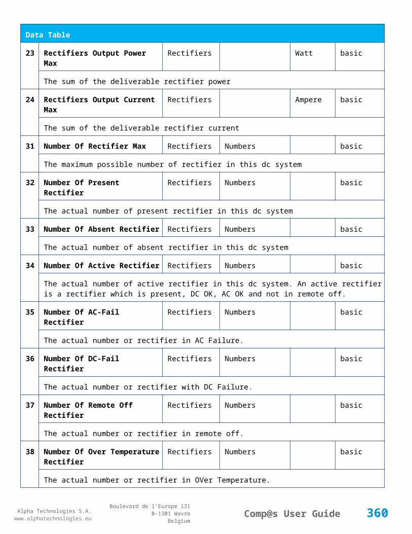
Alpha Technologies S.A.www.alphatechnologies.eu
Alpha Technologies S.A.www.alphatechnologies.eu
Comp@s User GuideBoulevard de l’Europe 131
B-1301 WavreBelgium
Control Table
Id Name Group SubGroup License
1 Back To Float System basic
The dc system must go back in floating mode.
2 Start Battery Test System battery
The dc system must start a battery test.
3 Force Battery Test System battery
The dc system must force a battery test.
4 Start Boost Mode System battery
The dc system must go in boost mode.
11 Open The LVD LVD basic
Try to open the LVD. It could not work if the LVD is electronic, and the request will be canceled after 15 sec.
12 Close The LVD LVD basic
The LVD must be closed
21 Correct Battery Current Offset Battery basic
31 Reset Battery Current Integration Battery basic
Reset the integration of the battery current.
41 Reset Last Battery Test State Battery battery
Reset the state of the last battery test. If an alarm 'Battery Last Test Failed' is set, the alarm will be cleared.
51 Save Configuration In MCU Save basic
Save configuration parameters in the MCU microcontroller. If comp@s is not present, the system will be correctly managed.
55 Set MCU Specific Configuration Id Advanced Factory basic
This control allows to reconfigure the MCU to support specific hardware configuration, with embedded distribution for example
61 Set Digital Input 4 Counter Value Digital Inputs Digital Input 4 basic
Set Counter Value
360

Alpha Technologies S.A.www.alphatechnologies.eu
Alpha Technologies S.A.www.alphatechnologies.eu
Comp@s User GuideBoulevard de l’Europe 131
B-1301 WavreBelgium
Control Table
111
Invert Relay 1 State For X Seconds Relays Relay 1 basic
Generate Pulse on relay 1
112
Invert Relay 2 State For X Seconds Relays Relay 2 basic
Generate Pulse on relay 2
113
Invert Relay 3 State For X Seconds Relays Relay 3 basic
Generate Pulse on relay 3
114
Invert Relay 4 State For X Seconds Relays Relay 4 basic
Generate Pulse on relay 4
501
Clear My Events Generic Events basic
By writing '1' to this control element, all the events of this equipment will be cleared.
502
Clear All Events Generic Events basic
By writing '1' to this control element, all the events of this equipment and all the events of all the sub-equipments will be cleared.
511
Add Event Generic Events basic
This control element adds an event of severity none. The event name is the text written to this control element
512
Add Major Event Generic Events basic
This control element adds an event of severity major. The event name is the text written to this control element
521
Reset Default Names And Groups Generic Renaming basic
This control element resets all the element Names, Groups and Subgroups to default values for this equipment
522
Reset Default Names And Groups Recursive Generic Renaming basic
This control element resets all the element Names, Groups and Subgroups to default values for this equipment and all sub equipments
7.2.15 MCU3096M6
Device Information
Name MCU3096M6
Short Description MCU for rack 6x3000W +96V
361

Alpha Technologies S.A.www.alphatechnologies.eu
Alpha Technologies S.A.www.alphatechnologies.eu
Comp@s User GuideBoulevard de l’Europe 131
B-1301 WavreBelgium
Device Information
Long Description
Hardware Reference 9413 063 07041
Software Reference SOFT 000091 XX
Equipment Type Monitoring Control Unit
ETSI Level /site/energy_system/dc_system
Description Table
Id Name Group SubGroup License
1 Description Description Custom Description basic
A free text zone to write a system description
2 Reference Description Custom Description basic
A free text zone to write the customer reference of the system
11 Product Name Description Product Info basic
The product name of the DC system monitoring
12 Hardware Reference Description Product Info basic
The hardware reference of the DC system monitoring
14 Software Reference Description Product Info asset
The serial number of the DC system monitoring
16 Serial Number Description Product Info asset
The serial number of the DC system monitoring
18 Manufacturing Date Description Product Info asset
The production date of the DC system monitoring
Alarm Table
Id Name Group SubGroup Severity Type (Level)
Set/Clear Delay
1 DC Bus Extra Low DC Bus major (6) 5 / 2
The bus voltage is extra low. The alarm is set when the bus voltage is lower than the configuration parameter 'DC Bus Voltage Extra Low'. There is an hysteresis on the alarm : 'DC Bus Voltage Extra Low
362

Alpha Technologies S.A.www.alphatechnologies.eu
Alpha Technologies S.A.www.alphatechnologies.eu
Comp@s User GuideBoulevard de l’Europe 131
B-1301 WavreBelgium
Alarm Table
Hysteresis'. The alarm is not activated when DC mode is BATTERY TEST
2 DC Bus Low DC Bus minor (4) 5 / 2
The bus voltage is low. The alarm is set when the bus voltage is lower than the configuration parameter 'DC Bus Voltage Low'. There is an hysteresis on the alarm : 'DC Bus Voltage Low Hysteresis'
3 DC Bus High DC Bus minor (4) 5 / 2
The bus voltage is high. The alarm is set when the bus voltage is higher than the configuration paramenter 'DC Bus Voltage High'. There is an hysterisis on the alarm : 'DC Bus Voltage High Hysteresis'
4 DC Bus Extra High DC Bus major (6) 5 / 2
The bus voltage is extra high. The alarm is set when the bus voltage is higher than the configuration paramenter 'DC Bus Voltage Extra High'. There is an hysterisis on the alarm : 'DC Bus Voltage Extra High Hysteresis'
5 DC Bus Voltage Sense Failure
DC Bus major (6) 5 / 2
The DC bus voltage sense is defective. The DC bus voltage is unconnected or unconfigured.
6 Mains Failure AC Bus minor (4) 5 / 2
The number of active rectifiers is equal to 0 and the number of rectifiers in AC failure is greater than 0.
7 Mains Partial Failure AC Bus minor (4) 10 / 2
The number of active rectifiers is greater than 0 and the number of rectifiers in AC failure is greater than 0. Some rectifiers are in AC Failure. It may be caused by an open breaker, a real phase failure, or by a rectifier failure.
8 Mains Low AC Bus warning (2) 10 / 2
The main voltage is low on one or more phases. No rectifier is in AC failure. If MCU master type is 30110, 3096 or 3048M6, an hysteresis _phase123Hysteresis is added to the voltage lower limit
9 Mains High AC Bus warning (2) 10 / 2
The main voltage is low on one or more phases. No rectifier is in AC failure. The alarm is only active if MCU master type is 30110, 3096 or 3048M6. Therefore, an hysteresis _phase123Hysteresis is substracted to the voltage lower limit.
10
One Rectifier Failure Rectifiers minor (4) 5 / 2
One rectifier must be replaced or is not powered correctly. The DC fail alarm of the rectifier is set. The number of rectifier with DC Failure is higher than 0, there is no mains failure, and the 'More Than One Rectifier Failure alarm is not set.'
11
More Than One Rectifier Failure
Rectifiers major (6) 10 / 2
363
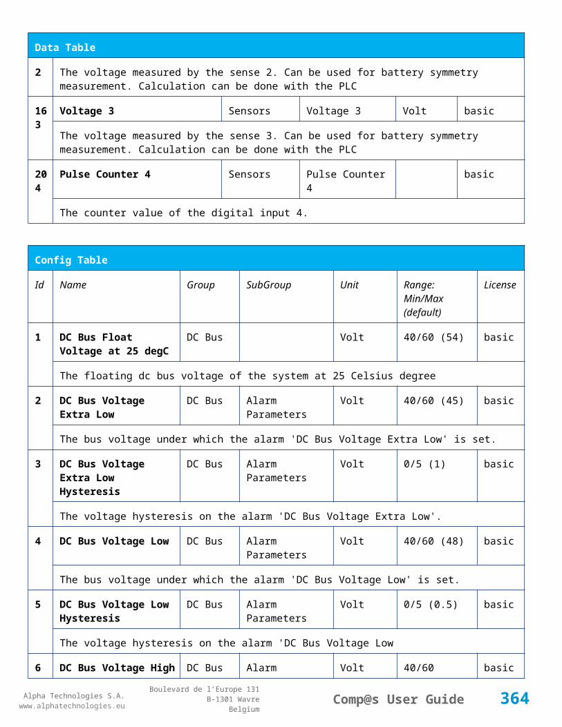
Alpha Technologies S.A.www.alphatechnologies.eu
Alpha Technologies S.A.www.alphatechnologies.eu
Comp@s User GuideBoulevard de l’Europe 131
B-1301 WavreBelgium
Alarm Table
There is no mains failure and number of rectifier failures is greater than 1.
12
Missing Rectifiers Rectifiers major (6) 5 / 2
There is not enough rectifier according to the configuration parameter : 'Minimal Number Of Rectifier'
13
Battery Last Test Failed Battery Battery Test minor (3) 5 / 2
The last battery test did not succeed and was not cancelled. Maybe the battery should be replaced.
14
Battery On Discharge Battery minor (4) 10 / 2
The battery is discharging. This means that the load is too high for the installed rectifiers. This alarm is inactive when the system in AC Failure or during a battery test. There is an hysteresis corresponding to battery parameter 'Is discharging current hysteresis'.
17
Battery LVD Relay Open LVD major (6) 5 / 2
The battery Low Voltage Disconnector is open. On Systems without LVD_Status signal, like MCU 1848 or MCU 1x6, the alarm is present only if the signal LVD_COM asks to open the LVD
18
Battery Temperature Too High
Battery Temperature minor (3) 5 / 2
The temperature of the battery is too high and is greater than -600 units. There is an hysteresis corresponding to battery parameter 'Temperature hysteresis'.
19
Battery Temperature Too Low
Battery Temperature minor (3) 5 / 2
The temperature of the battery is too low and is greater than -600 units. There is an hysteresis corresponding to battery parameter 'Temperature hysteresis'.
20
Battery Temperature Sensor Fail
Battery Temperature minor (3) 5 / 2
The battery temperature sensor (NTC) value is inferior to -500 units meaning that it is not connected or defective.
21
Ambient Temperature Too High
Sensors Temperature minor (0) 5 / 2
The ambient temperature is too high and is greater than -600 units. There is an hysteresis corresponding to parameter 'Ambiant temperature hysteresis'. This alarm is only activated on MCU master types 30110, 3096, 30125, 0024, 0948, 0548, 0348, 0948 and 3048M6.
22
Ambient Temperature Too Low
Sensors Temperature minor (0) 5 / 2
The ambient temperature is too low and is greater than -600 units. There is an hysteresis corresponding to parameter 'Ambiant temperature hysteresis'. This alarm is only activated on MCU master types 30110, 3096, 30125, 0024, 0948, 0548, 0348, 0948 and 3048M6.
2 Ambient Temperature Sensors Temperature minor (0) 5 / 2
364

Alpha Technologies S.A.www.alphatechnologies.eu
Alpha Technologies S.A.www.alphatechnologies.eu
Comp@s User GuideBoulevard de l’Europe 131
B-1301 WavreBelgium
Alarm Table
3 Sensor Fail
The ambiant temperature sensor (NTC) value is inferior to -500 units meaning that it is not connected or defective.
25
Distribution Breaker Open Digital Inputs major (6) 5 / 2
This alarm is related to digital input 1. This alarm is activated if digital input value is different to configuration parameter 'Digital Input Alarm Value'
26
Battery Breaker Open Digital Inputs minor (4) 5 / 2
This alarm is related to digital input 2. This alarm is activated if digital input value is different to configuration parameter 'Digital Input Alarm Value'
27
Digital Input 3 Digital Inputs none (0) 5 / 2
This alarm is related to digital input 3. This alarm is activated if digital input value is different to configuration parameter 'Digital Input Alarm Value'
28
Digital Input 4 Digital Inputs none (0) 5 / 2
This alarm is related to digital input 4. This alarm is activated if digital input value is different to configuration parameter 'Digital Input Alarm Value'
29
Digital Input 5 Digital Inputs none (0) 5 / 2
This alarm is related to digital input 5. This alarm is activated if digital input value is different to configuration parameter 'Digital Input Alarm Value'
30
Digital Input 6 Digital Inputs none (0) 5 / 2
This alarm is related to digital input 6. This alarm is activated if digital input value is different to configuration parameter 'Digital Input Alarm Value'
31
Digital Input 7 Digital Inputs none (0) 5 / 2
This alarm is related to digital input 7. This alarm is activated if digital input value is different to configuration parameter 'Digital Input Alarm Value'
32
Digital Input 8 Digital Inputs none (0) 5 / 2
This alarm is related to digital input 8. This alarm is activated if digital input value is different to configuration parameter 'Digital Input Alarm Value'
Data Table
Id Name Group SubGroup Unit License
1 DC Mode System basic
The DC system can have 4 values: 'FLOAT', 'BOOST', 'BATTERY_TEST', 'AC_FAILURE' or SAFE
365

Alpha Technologies S.A.www.alphatechnologies.eu
Alpha Technologies S.A.www.alphatechnologies.eu
Comp@s User GuideBoulevard de l’Europe 131
B-1301 WavreBelgium
Data Table
2 Previous DC Mode System basic
The previous value of the DC Mode
11 Bus Voltage DC Bus Volt basic
The DC bus voltage in volt.
12 Ratio Delivered On Available Power
System % basic
This is the ratio of the delivered power divided by the installed power, in %.
13 Minutes Since Last AC Failure Begin
AC Bus minute basic
The number of minute since the last AC Failure begin
14 Minutes Since Last AC Failure End
AC Bus minute basic
The number of minute since the last AC Failure end
21 Rectifiers Output Power Rectifiers Watt basic
The sum of the delivered rectifier power
22 Rectifiers Output Current Rectifiers Ampere basic
The sum of the delivered rectifier current
23 Rectifiers Output Power Max Rectifiers Watt basic
The sum of the deliverable rectifier power
24 Rectifiers Output Current Max Rectifiers Ampere basic
The sum of the deliverable rectifier current
31 Number Of Rectifier Max Rectifiers Numbers basic
The maximum possible number of rectifier in this dc system
32 Number Of Present Rectifier Rectifiers Numbers basic
The actual number of present rectifier in this dc system
33 Number Of Absent Rectifier Rectifiers Numbers basic
The actual number of absent rectifier in this dc system
34 Number Of Active Rectifier Rectifiers Numbers basic
The actual number of active rectifier in this dc system. An active rectifier is a rectifier which is present,
366

Alpha Technologies S.A.www.alphatechnologies.eu
Alpha Technologies S.A.www.alphatechnologies.eu
Comp@s User GuideBoulevard de l’Europe 131
B-1301 WavreBelgium
Data Table
DC OK, AC OK and not in remote off.
35 Number Of AC-Fail Rectifier Rectifiers Numbers basic
The actual number or rectifier in AC Failure.
36 Number Of DC-Fail Rectifier Rectifiers Numbers basic
The actual number or rectifier with DC Failure.
37 Number Of Remote Off Rectifier Rectifiers Numbers basic
The actual number or rectifier in remote off.
38 Number Of Over Temperature Rectifier
Rectifiers Numbers basic
The actual number or rectifier in OVer Temperature.
41 Mains Phase 1 Voltage AC Bus Volt basic
The voltage on AC phase 1
42 Mains Phase 2 Voltage AC Bus Volt basic
The voltage on AC phase 2
43 Mains Phase 3 Voltage AC Bus Volt basic
The voltage on AC phase 3
51 Load Power Load Watt basic
Estimation of the load power consumption
52 Load Current Load Ampere basic
Estimation of the load current consumption
61 Battery Input Current Battery Ampere basic
Measurement of the battery input current. A negative value means that the battery is discharging
62 Battery Input Power Battery Watt basic
Measurement of the battery input power. A negative value means that the battery is discharging
71 Battery Temperature Battery Temperature degree C basic
The battery temperature
72 Battery Test State Battery Battery Test basic
This is about the result of the last battery test. 9 values are possible : NEVER_TESTED, SUCCESS,
367

Alpha Technologies S.A.www.alphatechnologies.eu
Alpha Technologies S.A.www.alphatechnologies.eu
Comp@s User GuideBoulevard de l’Europe 131
B-1301 WavreBelgium
Data Table
ON_GOING, FAILED_TIMEOUT, FAILED_VBUS_TOO_LOW, FAILED_LOAD_TOO_LOW, FAILED_AC_FAILURE, FAILED_CANCELED, FAILED_LVD_OPENED
73 Battery Test Discharged Capacity Ratio
Battery Battery Test % basic
This is the battery capacity, in percent, discharged during the last battery test. This value is updated at the end of the battery test.
74 Battery Test Discharged Capacity
Battery Battery Test Ah basic
This is the battery capacity, in ampere hour, discharged during the last battery test. This value is updated at the end of the battery test.
75 Battery Test Final Voltage Battery Battery Test % basic
This is the bus voltage at the end of the last battery test. This value is updated at the end of the battery test.
81 Previous Battery Test State Battery Battery Test basic
The result of the previous battery test
82 Minutes Since Last Test Battery Battery Battery Test basic
The number of minute without battery test
84 Next Scheduled Battery Test Battery Battery Test basic
The date and time of the next time the scheduled battery test will run
91 Battery Charge Capacity Battery % basic
The battery charge capacity, calculated by integration of the current.
92 Calculated Autonomy Battery minute basic
Calculation of the remaining autonomy
93 Battery Current Integration Battery As basic
Actual value of the integration of the current, in Ampere * second
94 Battery Current Integration Battery Ah basic
Actual value of the integration of the current, in Ampere * hour
101
LVD State LVD basic
Actual state of the LVD
11 Relay 1 State Relays Relay 1 basic
368
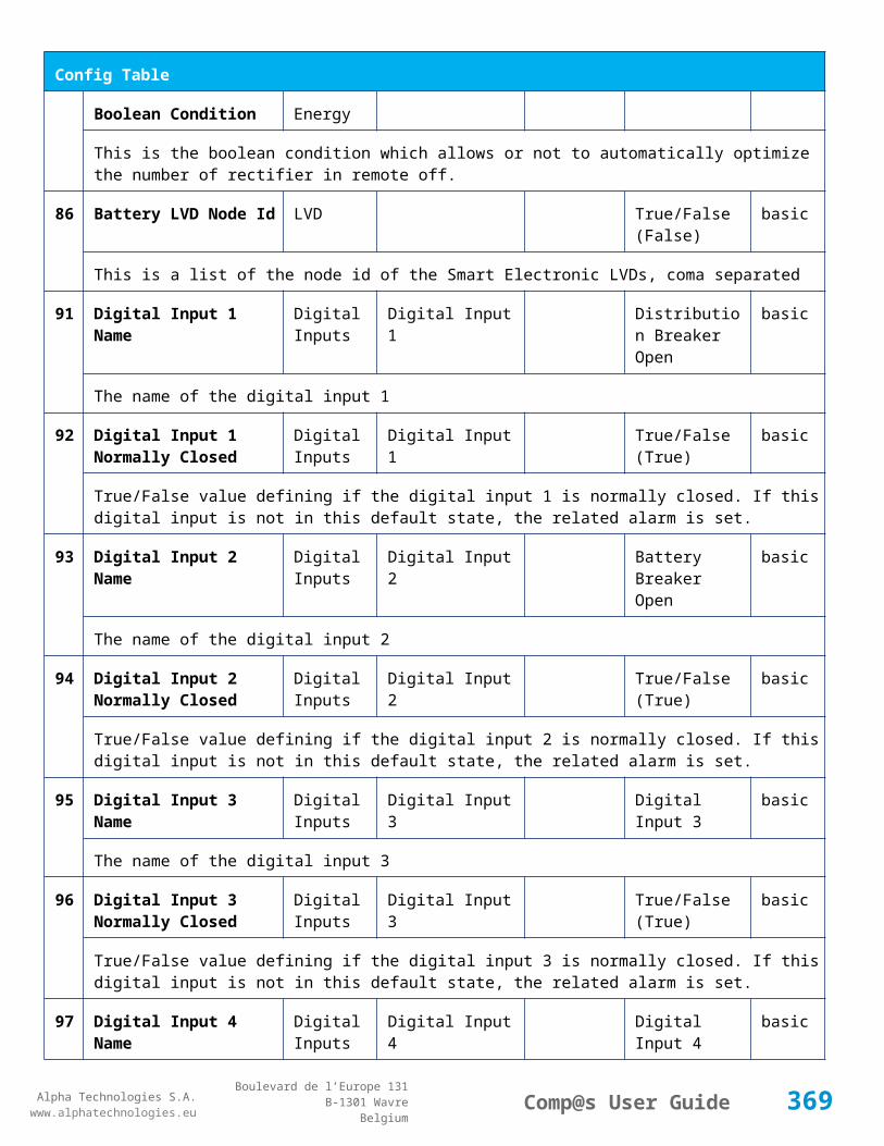
Alpha Technologies S.A.www.alphatechnologies.eu
Alpha Technologies S.A.www.alphatechnologies.eu
Comp@s User GuideBoulevard de l’Europe 131
B-1301 WavreBelgium
Data Table
1 Actual state of the Relay 1
112
Relay 2 State Relays Relay 2 basic
Actual state of the Relay 2
113
Relay 3 State Relays Relay 3 basic
Actual state of the Relay 3
114
Relay 4 State Relays Relay 4 basic
Actual state of the Relay 3
121
Efficiency Optimized Number Of Rectifier
Smart Energy asset
The optimal number of ON rectifier for Efficiency Optimization
122
System Loss Without Optimisation
Smart Energy Watt underdev
Estimation of the losses without optimisation
123
System Loss With Optimisation Smart Energy Watt underdev
Estimation of the losses with optimisation
124
Rectifier Model Used For Calculation
Smart Energy asset
The rectifier model used
125
Smart Energy Savings Smart Energy Watt asset
Estimation of the losses with optimisation
151
Ambient Temperature Sensors Temperature degree C basic
The ambiant temperature (second temperature sense)
161
Voltage 1 Sensors Voltage 1 Volt basic
The voltage measured by the sense 1. Can be used for battery symmetry measurement. Calculation can be done with the PLC
162
Voltage 2 Sensors Voltage 2 Volt basic
The voltage measured by the sense 2. Can be used for battery symmetry measurement. Calculation can be done with the PLC
163
Voltage 3 Sensors Voltage 3 Volt basic
The voltage measured by the sense 3. Can be used for battery symmetry measurement. Calculation
369

Alpha Technologies S.A.www.alphatechnologies.eu
Alpha Technologies S.A.www.alphatechnologies.eu
Comp@s User GuideBoulevard de l’Europe 131
B-1301 WavreBelgium
Data Table
can be done with the PLC
204
Pulse Counter 4 Sensors Pulse Counter 4 basic
The counter value of the digital input 4.
Config Table
Id Name Group SubGroup Unit Range: Min/Max (default)
License
1 DC Bus Float Voltage at 25 degC
DC Bus Volt 65/105 (94.5) basic
The floating dc bus voltage of the system at 25 Celsius degree
2 DC Bus Voltage Extra Low
DC Bus Alarm Parameters Volt 65/105 (78.75) basic
The bus voltage under which the alarm 'DC Bus Voltage Extra Low' is set.
3 DC Bus Voltage Extra Low Hysteresis
DC Bus Alarm Parameters Volt 0.5/10 (2) basic
The voltage hysteresis on the alarm 'DC Bus Voltage Extra Low'.
4 DC Bus Voltage Low DC Bus Alarm Parameters Volt 65/105 (84) basic
The bus voltage under which the alarm 'DC Bus Voltage Low' is set.
5 DC Bus Voltage Low Hysteresis
DC Bus Alarm Parameters Volt 0.5/10 (1) basic
The voltage hysteresis on the alarm 'DC Bus Voltage Low
6 DC Bus Voltage High DC Bus Alarm Parameters Volt 70/105 (98.875) basic
The bus voltage over which the alarm 'DC Bus Voltage High' is set.
7 DC Bus Voltage High Hysteresis
DC Bus Alarm Parameters Volt 0.5/10 (1) basic
The voltage hysteresis on the alarm 'DC Bus Voltage High
8 DC Bus Voltage Extra High
DC Bus Alarm Parameters Volt 70/105 (101.5) basic
The bus voltage over which the alarm 'DC Bus Voltage Extra High' is set.
9 DC Bus Voltage Extra High Hysteresis
DC Bus Alarm Parameters Volt 0.5/10 (1) basic
370

Alpha Technologies S.A.www.alphatechnologies.eu
Alpha Technologies S.A.www.alphatechnologies.eu
Comp@s User GuideBoulevard de l’Europe 131
B-1301 WavreBelgium
Config Table
The voltage hysteresis on the alarm 'DC Bus Voltage Extra High
10 LVD Disconnect Voltage LVD Volt 65/87.5 (75.6) basic
The dc bus voltage under which the battery must be disconnected of the bus. This allows preserving the battery life. The load will be unpowered.
11 LVD Disconnect Delay LVD second 1/4000 (1) basic
The delay in second before disconnecting the battery if the dc bus voltage is under the configured disconnected voltage. This avoids disconnection during a low bus transient.
21 Temperature Compensation Slope
Battery Temperature Compensation
mV/degree -2000/0 (-126) basic
The slope of the battery temperature compensation in mv/degree. For a 48V system, -72mV/degree is often used.
22 Maximum Positive Temperature Compensation
Battery Temperature Compensation
Volt 0/20 (6) basic
The maximal allowed positive compensation.
23 Maximum Negative Temperature Compensation
Battery Temperature Compensation
Volt -20/0 (-6) basic
The maximal allowed negative compensation.
25 Minimal Number Of Present Rectifiers
Rectifiers Alarm Parameters 0/100 (0) basic
The minimal number of rectifier which must be present. If there is less present rectifiers, the alarm 'Missing Rectifiers' is set.
26 Rectifier Model Rectifiers basic
The rectifier model
27 Forced Remote Off Rectifers
Rectifiers basic
A list of rectifier which are forced in remote off. The id of the rectifier must be coma separated. Ex: 1,3 will maintain rectifier 1 and 3 off.
31 Battery Charge Current Limit
Battery Battery Charge Parameters
Ampere 0.5/1000 (1000) basic
The maximal battery current when the battery is charging. The monitoring regulates the bus voltage in order to satisfy this condition. This parameter is often equal to the nominal battery capacity divided by 10.
32 Battery String Capacity Battery Ah 3/1000 (100) basic
371

Alpha Technologies S.A.www.alphatechnologies.eu
Alpha Technologies S.A.www.alphatechnologies.eu
Comp@s User GuideBoulevard de l’Europe 131
B-1301 WavreBelgium
Config Table
The battery capacity in Ah.
33 Battery Temperature Low
Battery Alarm Parameters degree C -100/20 (0) basic
The temperature under which the alarm 'Battery Temperature Too Low' must be set.
34 Battery Temperature High
Battery Alarm Parameters degree C 5/100 (40) basic
The temperature over which the alarm 'Battery Temperature Too High' must be set.
35 Battery Temperature Hysteresis
Battery Alarm Parameters degree C 0/10 (2) basic
The hysteresis on the 'Battery Temperature Too High' and 'Battery Temperature Too Low' alarms.
36 Minimal Current For Discharging Alarm
Battery Alarm Parameters Ampere 0/1000 (3) basic
The minimal discharging current to set the 'Battery On Discharge' alarm.
37 Current Hysteresis For Discharging Alarm
Battery Alarm Parameters Ampere 0/50 (1) basic
The hysteresis on the 'Battery On Discharge' alarm.
41 Shunt Rating At 60mV Current Sensors
Shunt 1 Ampere 25/5000 (250) basic
The rating of the battery shunt at 60mV.
51 Boost Automatic Battery Boost False/False (False)
battery
The boost mode must be automatically after the fact that during a mains failure, the bus voltage went under the configured 'Boost Activation Low Voltage'. This allows charging the battery faster.
52 Boost Activation Low Voltage
Battery Boost Volt 75.25/87.5 (80.5)
battery
The voltage under which the boost mode can be activated.
53 Boost Termination Voltage
Battery Boost Volt 87.5/101.5 (98.7)
battery
The voltage over which the system must go back to floating mode.
54 Boost Termination Current
Battery Boost Ampere 0/100 (4) battery
The battery charging current under which the system must go back to floating mode.
55 Boost Termination Time Battery Boost minute 10/240 (120) battery
372
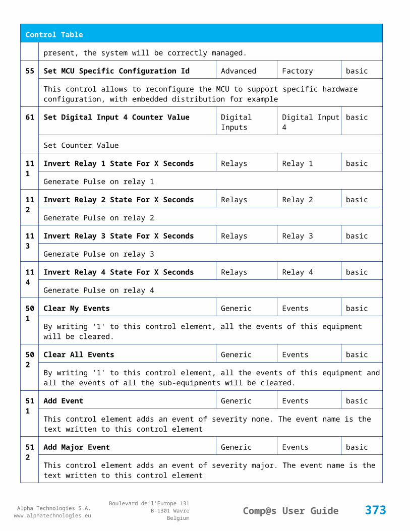
Alpha Technologies S.A.www.alphatechnologies.eu
Alpha Technologies S.A.www.alphatechnologies.eu
Comp@s User GuideBoulevard de l’Europe 131
B-1301 WavreBelgium
Config Table
The time in minute after which the system must go back in floating mode.
70 Battery Test End Voltage
Battery Battery Test Volt 52.5/105 (80.5) battery
The voltage at which any battery test must be stopped.
71 Battery Test Discharge Ratio
Battery Battery Test % 0/100 (0) battery
The ratio of the battery capacity to discharge. If 30 is set, 30% of the battery will be discharged during the test
72 Battery Test Interval Battery Battery Test day 0/3000 (0) battery
The number of days between two automatically started battery test. If this parameter is set to 0, the battery test is not started automatically. The user can remotely or locally start or force this test.
73 Battery Test Discharge Current
Battery Battery Test Ampere 10/5000 (2000) battery
The current at which the battery must be discharged during a battery test. The monitoring regulates the bus voltage in order to satisfy this condition. The load current must be of course higher than this parameter.
74 Battery Test Minimal Discharge Current
Battery Battery Test Ampere 2/90 (2) battery
The battery current under which the battery test must be stopped because the load is too low.
75 Battery Test Time Out Battery Battery Test minute 1/5000 (10) battery
The timeout in minute after which the battery test must be stopped.
76 Battery Test Requested Minutes Without Mains Failure
Battery Battery Test minute 0/5000 (1440) battery
The minimal time in minute without mains failure in order to allow a battery start. This parameter is not taken into account when the battery test is forced.
77 Battery Test Scheduler Cron Rule
Battery Battery Test basic
83 Smart Energy Boolean Condition
Smart Energy
asset
This is the boolean condition which allows or not to automatically optimize the number of rectifier in remote off.
86 Battery LVD Node Id LVD True/False (False)
basic
373
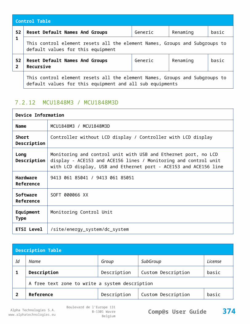
Alpha Technologies S.A.www.alphatechnologies.eu
Alpha Technologies S.A.www.alphatechnologies.eu
Comp@s User GuideBoulevard de l’Europe 131
B-1301 WavreBelgium
Config Table
This is a list of the node id of the Smart Electronic LVDs, coma separated
91 Digital Input 1 Name Digital Inputs
Digital Input 1 Distribution Breaker Open
basic
The name of the digital input 1
92 Digital Input 1 Normally Closed
Digital Inputs
Digital Input 1 True/False (True)
basic
True/False value defining if the digital input 1 is normally closed. If this digital input is not in this default state, the related alarm is set.
93 Digital Input 2 Name Digital Inputs
Digital Input 2 Battery Breaker Open
basic
The name of the digital input 2
94 Digital Input 2 Normally Closed
Digital Inputs
Digital Input 2 True/False (True)
basic
True/False value defining if the digital input 2 is normally closed. If this digital input is not in this default state, the related alarm is set.
95 Digital Input 3 Name Digital Inputs
Digital Input 3 Digital Input 3 basic
The name of the digital input 3
96 Digital Input 3 Normally Closed
Digital Inputs
Digital Input 3 True/False (True)
basic
True/False value defining if the digital input 3 is normally closed. If this digital input is not in this default state, the related alarm is set.
97 Digital Input 4 Name Digital Inputs
Digital Input 4 Digital Input 4 basic
The name of the digital input 4
98 Digital Input 4 Normally Closed
Digital Inputs
Digital Input 4 True/False (True)
basic
True/False value defining if the digital input 4 is normally closed. If this digital input is not in this default state, the related alarm is set.
99 Digital Input 5 Name Digital Inputs
Digital Input 5 Digital Input 5 basic
The name of the digital input 5
100
Digital Input 5 Normally Closed
Digital Inputs
Digital Input 5 True/False (True)
basic
374

Alpha Technologies S.A.www.alphatechnologies.eu
Alpha Technologies S.A.www.alphatechnologies.eu
Comp@s User GuideBoulevard de l’Europe 131
B-1301 WavreBelgium
Config Table
True/False value defining if the digital input 5 is normally closed. If this digital input is not in this default state, the related alarm is set.
101
Digital Input 6 Name Digital Inputs
Digital Input 6 Digital Input 6 basic
The name of the digital input 6
102
Digital Input 6 Normally Closed
Digital Inputs
Digital Input 6 True/False (True)
basic
True/False value defining if the digital input 6 is normally closed. If this digital input is not in this default state, the related alarm is set.
103
Digital Input 7 Name Digital Inputs
Digital Input 7 Digital Input 7 basic
The name of the digital input 7
104
Digital Input 7 Normally Closed
Digital Inputs
Digital Input 7 True/False (True)
basic
True/False value defining if the digital input 7 is normally closed. If this digital input is not in this default state, the related alarm is set.
105
Digital Input 8 Name Digital Inputs
Digital Input 8 Digital Input 8 basic
The name of the digital input 8
106
Digital Input 8 Normally Closed
Digital Inputs
Digital Input 8 True/False (True)
basic
True/False value defining if the digital input 8 is normally closed. If this digital input is not in this default state, the related alarm is set.
111
Dry Alarm 1 Alternative Boolean Condition
Relays Relay 1 plc
Another Boolean condition to activate the dry alarm relay 1. The way to define boolean condition is detailed in the PLC chapter.
112
Dry Alarm 2 Alternative Boolean Condition
Relays Relay 2 plc
Another Boolean condition to activate the dry alarm relay 2. The way to define boolean condition is detailed in the PLC chapter.
113
Dry Alarm 3 Alternative Boolean Condition
Relays Relay 3 plc
Another Boolean condition to activate the dry alarm relay 3. The way to define boolean condition is detailed in the PLC chapter.
375
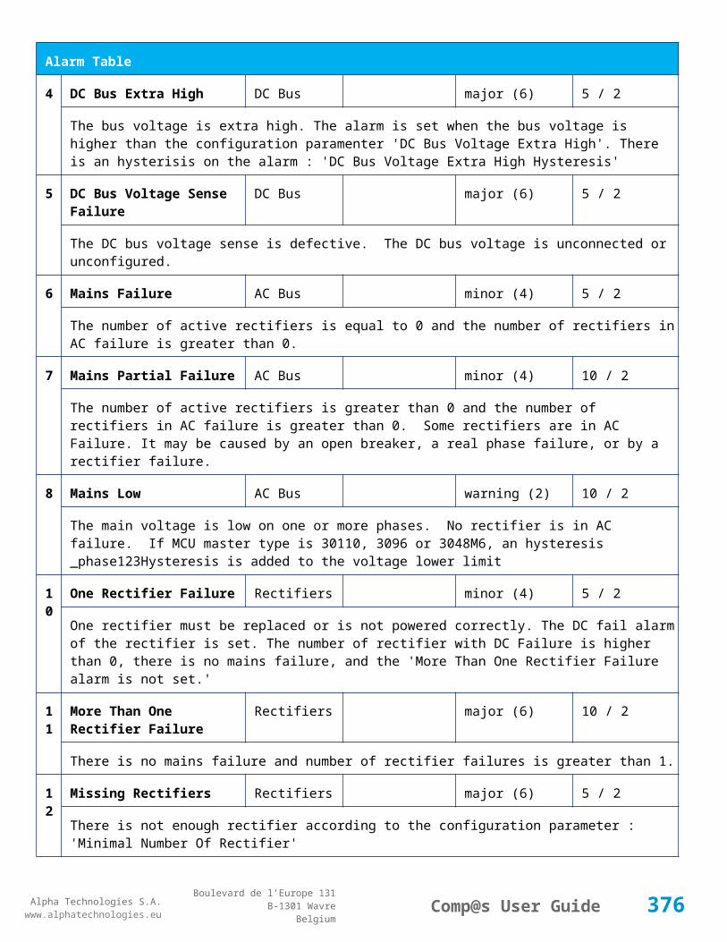
Alpha Technologies S.A.www.alphatechnologies.eu
Alpha Technologies S.A.www.alphatechnologies.eu
Comp@s User GuideBoulevard de l’Europe 131
B-1301 WavreBelgium
Config Table
114
Dry Alarm 4 Alternative Boolean Condition
Relays Relay 4 plc
Another Boolean condition to activate the dry alarm relay 4. The way to define boolean condition is detailed in the PLC chapter.
131
Ambient Temperature Low
Sensors Temperature degree C basic
The temperature under which the alarm 'Ambiant Temperature Too Low' must be set.
132
Ambient Temperature High
Sensors Temperature degree C basic
The temperature under which the alarm 'Ambiant Temperature Too Low' must be set.
133
Ambient Temperature Hysteresis
Sensors Temperature degree C basic
The hysteresis on the 'Battery Temperature Too High' and 'Battery Temperature Too Low' alarms.
141
AC Voltage Low Mains Volt 0/240 (180) basic
The AC voltage under which the alarm AC Low is set.
142
AC Voltage High Mains Volt 80/600 (250) basic
The AC voltage over which the alarm AC High is set.
143
AC Voltage Hysteresis Mains Volt 0/40 (5) basic
The AC voltage hysteresis on alarms AC High and AC Low.
144
AC Phase 1 PLC AC Bus basic
This is the mathematical expression of the calculation of AC phase 1. If empty, the rectifiers are used. The syntax for writting mathematical expression is described in the PLC chapter. The PLC data element is the result of the calculation.
145
AC Phase 2 PLC AC Bus basic
This is the mathematical expression of the calculation of AC phase 2. If empty, the rectifiers are used. The syntax for writting mathematical expression is described in the PLC chapter. The PLC data element is the result of the calculation.
146
AC Phase 3 PLC AC Bus basic
This is the mathematical expression of the calculation of AC phase 3. If empty, the rectifiers are used. The syntax for writting mathematical expression is described in the PLC chapter. The PLC data element is the result of the calculation.
521
Read Access User Numbers
Generic Allowed Users (1,2,3,4,5) basic
376

Alpha Technologies S.A.www.alphatechnologies.eu
Alpha Technologies S.A.www.alphatechnologies.eu
Comp@s User GuideBoulevard de l’Europe 131
B-1301 WavreBelgium
Config Table
The list of the user numbers which have read access to this equipment. The user numbers are coma separated. The accepted user id are 1,2,3,4 and 5. Ex: 1,3,4
522
Write Access User Numbers
Generic Allowed Users () basic
The list of the user numbers which have write access to this equipment. This means that these users can modify the configuration element, the alarm settings and use the control elements. The user numbers are coma separated. The accepted user ids are 1,2,3,4 and 5. Ex: 1,3,4
601
Event Table Length Generic Events 10/4000 (100) basic
The maximum length of the table. The value must be comprised between 10 and 4000
602
Event Table Length By Rectifier
Generic Events 10/4000 (100) basic
The maximum length of the table. The value must be comprised between 10 and 4000
901
Number Of PLC Data PLC (0) plc
The number of PLC data. Every equipment can manage up to 20 user programmable data. Data elements are automatically added in the data table. Configuration parameters are added to set the PLC Data Name and the PLC Data Mathematical calculation. In order to use these functionalities, you need a license with the 'PLC' module
902
Number Of PLC Alarm PLC (0) plc
The number of PLC alarm. Every equipment can manage up to 20 user programmable alarms. Alarm elements are automatically added in the alarm table. The alarm parameters are added to set the PLC Alarm Name and the PLC Alarm Boolean condition. In order to use these functionalities, you need a licence with the 'PLC' module
Control Table
Id Name Group SubGroup License
1 Back To Float System basic
The dc system must go back in floating mode.
2 Start Battery Test System battery
The dc system must start a battery test.
3 Force Battery Test System battery
The dc system must force a battery test.
4 Start Boost Mode System battery
The dc system must go in boost mode.
377
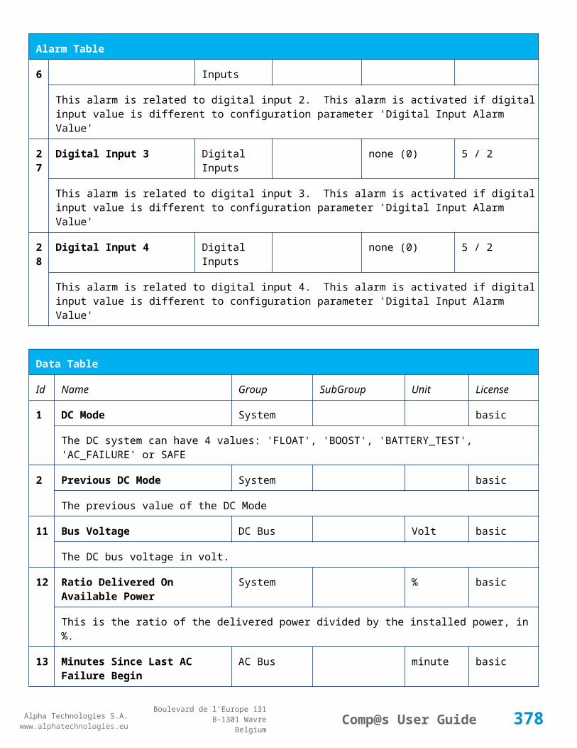
Alpha Technologies S.A.www.alphatechnologies.eu
Alpha Technologies S.A.www.alphatechnologies.eu
Comp@s User GuideBoulevard de l’Europe 131
B-1301 WavreBelgium
Control Table
11 Open The LVD LVD basic
Try to open the LVD. It could not work if the LVD is electronic, and the request will be canceled after 15 sec.
12 Close The LVD LVD basic
The LVD must be closed
21 Correct Battery Current Offset Battery basic
31 Reset Battery Current Integration Battery basic
Reset the integration of the battery current.
41 Reset Last Battery Test State Battery battery
Reset the state of the last battery test. If an alarm 'Battery Last Test Failed' is set, the alarm will be cleared.
51 Save Configuration In MCU Save basic
Save configuration parameters in the MCU microcontroller. If comp@s is not present, the system will be correctly managed.
55 Set MCU Specific Configuration Id Advanced Factory basic
This control allows to reconfigure the MCU to support specific hardware configuration, with embedded distribution for example
61 Set Digital Input 4 Counter Value Digital Inputs Digital Input 4 basic
Set Counter Value
111
Invert Relay 1 State For X Seconds Relays Relay 1 basic
Generate Pulse on relay 1
112
Invert Relay 2 State For X Seconds Relays Relay 2 basic
Generate Pulse on relay 2
113
Invert Relay 3 State For X Seconds Relays Relay 3 basic
Generate Pulse on relay 3
114
Invert Relay 4 State For X Seconds Relays Relay 4 basic
Generate Pulse on relay 4
50 Clear My Events Generic Events basic
378

Alpha Technologies S.A.www.alphatechnologies.eu
Alpha Technologies S.A.www.alphatechnologies.eu
Comp@s User GuideBoulevard de l’Europe 131
B-1301 WavreBelgium
Control Table
1 By writing '1' to this control element, all the events of this equipment will be cleared.
502
Clear All Events Generic Events basic
By writing '1' to this control element, all the events of this equipment and all the events of all the sub-equipments will be cleared.
511
Add Event Generic Events basic
This control element adds an event of severity none. The event name is the text written to this control element
512
Add Major Event Generic Events basic
This control element adds an event of severity major. The event name is the text written to this control element
521
Reset Default Names And Groups Generic Renaming basic
This control element resets all the element Names, Groups and Subgroups to default values for this equipment
522
Reset Default Names And Groups Recursive Generic Renaming basic
This control element resets all the element Names, Groups and Subgroups to default values for this equipment and all sub equipments
7.2.16 MCU30110M6
Device Information
Name MCU30110M6
Short Description Controller without LCD display (6x3kW - 110V)
Long Description Monitoring and control unit with USB and Ethernet port - ACE306 (+110V & +125V) line
Hardware Reference
9413 063 07011
Software Reference SOFT 000040 XX
Equipment Type Monitoring Control Unit
ETSI Level /site/energy_system/dc_system
Description Table
Id Name Group SubGroup License
379

Alpha Technologies S.A.www.alphatechnologies.eu
Alpha Technologies S.A.www.alphatechnologies.eu
Comp@s User GuideBoulevard de l’Europe 131
B-1301 WavreBelgium
Description Table
1 Description Description Custom Description basic
A free text zone to write a system description
2 Reference Description Custom Description basic
A free text zone to write the customer reference of the system
11 Product Name Description Product Info basic
The product name of the DC system monitoring
12 Hardware Reference Description Product Info basic
The hardware reference of the DC system monitoring
14 Software Reference Description Product Info asset
The serial number of the DC system monitoring
16 Serial Number Description Product Info asset
The serial number of the DC system monitoring
18 Manufacturing Date Description Product Info asset
The production date of the DC system monitoring
Alarm Table
Id Name Group SubGroup Severity Type (Level)
Set/Clear Delay
1 DC Bus Extra Low DC Bus major (6) 5 / 2
The bus voltage is extra low. The alarm is set when the bus voltage is lower than the configuration parameter 'DC Bus Voltage Extra Low'. There is an hysteresis on the alarm : 'DC Bus Voltage Extra Low Hysteresis'. The alarm is not activated when DC mode is BATTERY TEST
2 DC Bus Low DC Bus minor (4) 5 / 2
The bus voltage is low. The alarm is set when the bus voltage is lower than the configuration parameter 'DC Bus Voltage Low'. There is an hysteresis on the alarm : 'DC Bus Voltage Low Hysteresis'
3 DC Bus High DC Bus minor (4) 5 / 2
The bus voltage is high. The alarm is set when the bus voltage is higher than the configuration paramenter 'DC Bus Voltage High'. There is an hysterisis on the alarm : 'DC Bus Voltage High Hysteresis'
4 DC Bus Extra High DC Bus major (6) 5 / 2
380

Alpha Technologies S.A.www.alphatechnologies.eu
Alpha Technologies S.A.www.alphatechnologies.eu
Comp@s User GuideBoulevard de l’Europe 131
B-1301 WavreBelgium
Alarm Table
The bus voltage is extra high. The alarm is set when the bus voltage is higher than the configuration paramenter 'DC Bus Voltage Extra High'. There is an hysterisis on the alarm : 'DC Bus Voltage Extra High Hysteresis'
5 DC Bus Voltage Sense Failure
DC Bus major (6) 5 / 2
The DC bus voltage sense is defective. The DC bus voltage is unconnected or unconfigured.
6 Mains Failure AC Bus minor (4) 5 / 2
The number of active rectifiers is equal to 0 and the number of rectifiers in AC failure is greater than 0.
7 Mains Partial Failure AC Bus minor (4) 10 / 2
The number of active rectifiers is greater than 0 and the number of rectifiers in AC failure is greater than 0. Some rectifiers are in AC Failure. It may be caused by an open breaker, a real phase failure, or by a rectifier failure.
8 Mains Low AC Bus warning (2) 10 / 2
The main voltage is low on one or more phases. No rectifier is in AC failure. If MCU master type is 30110, 3096 or 3048M6, an hysteresis _phase123Hysteresis is added to the voltage lower limit
9 Mains High AC Bus warning (2) 10 / 2
The main voltage is low on one or more phases. No rectifier is in AC failure. The alarm is only active if MCU master type is 30110, 3096 or 3048M6. Therefore, an hysteresis _phase123Hysteresis is substracted to the voltage lower limit.
10
One Rectifier Failure Rectifiers minor (4) 5 / 2
One rectifier must be replaced or is not powered correctly. The DC fail alarm of the rectifier is set. The number of rectifier with DC Failure is higher than 0, there is no mains failure, and the 'More Than One Rectifier Failure alarm is not set.'
11
More Than One Rectifier Failure
Rectifiers major (6) 10 / 2
There is no mains failure and number of rectifier failures is greater than 1.
12
Missing Rectifiers Rectifiers major (6) 5 / 2
There is not enough rectifier according to the configuration parameter : 'Minimal Number Of Rectifier'
13
Battery Last Test Failed Battery Battery Test minor (3) 5 / 2
The last battery test did not succeed and was not cancelled. Maybe the battery should be replaced.
14
Battery On Discharge Battery minor (4) 10 / 2
The battery is discharging. This means that the load is too high for the installed rectifiers. This alarm is inactive when the system in AC Failure or during a battery test. There is an hysteresis corresponding to battery parameter 'Is discharging current hysteresis'.
381
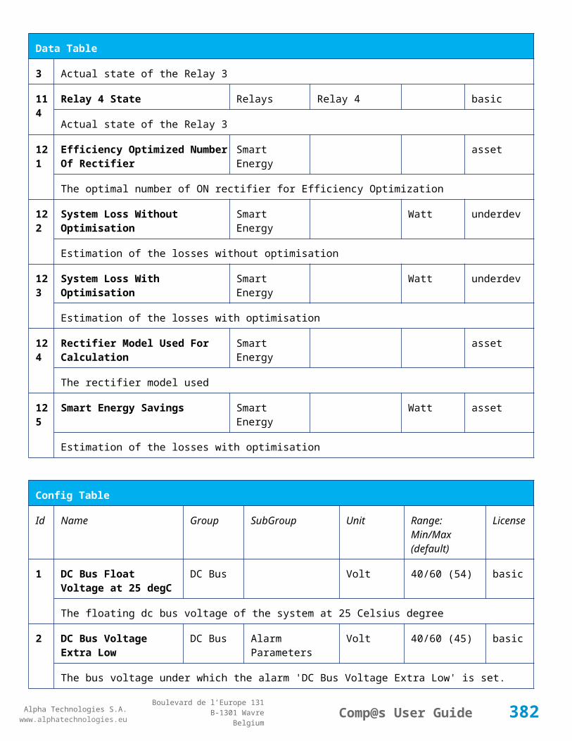
Alpha Technologies S.A.www.alphatechnologies.eu
Alpha Technologies S.A.www.alphatechnologies.eu
Comp@s User GuideBoulevard de l’Europe 131
B-1301 WavreBelgium
Alarm Table
17
Battery LVD Relay Open LVD major (6) 5 / 2
The battery Low Voltage Disconnector is open. On Systems without LVD_Status signal, like MCU 1848 or MCU 1x6, the alarm is present only if the signal LVD_COM asks to open the LVD
18
Battery Temperature Too High
Battery Temperature minor (3) 5 / 2
The temperature of the battery is too high and is greater than -600 units. There is an hysteresis corresponding to battery parameter 'Temperature hysteresis'.
19
Battery Temperature Too Low
Battery Temperature minor (3) 5 / 2
The temperature of the battery is too low and is greater than -600 units. There is an hysteresis corresponding to battery parameter 'Temperature hysteresis'.
20
Battery Temperature Sensor Fail
Battery Temperature minor (3) 5 / 2
The battery temperature sensor (NTC) value is inferior to -500 units meaning that it is not connected or defective.
21
Ambient Temperature Too High
Sensors Temperature minor (0) 5 / 2
The ambient temperature is too high and is greater than -600 units. There is an hysteresis corresponding to parameter 'Ambiant temperature hysteresis'. This alarm is only activated on MCU master types 30110, 3096, 30125, 0024, 0948, 0548, 0348, 0948 and 3048M6.
22
Ambient Temperature Too Low
Sensors Temperature minor (0) 5 / 2
The ambient temperature is too low and is greater than -600 units. There is an hysteresis corresponding to parameter 'Ambiant temperature hysteresis'. This alarm is only activated on MCU master types 30110, 3096, 30125, 0024, 0948, 0548, 0348, 0948 and 3048M6.
23
Ambient Temperature Sensor Fail
Sensors Temperature minor (0) 5 / 2
The ambiant temperature sensor (NTC) value is inferior to -500 units meaning that it is not connected or defective.
25
Distribution Breaker Open Digital Inputs major (6) 5 / 2
This alarm is related to digital input 1. This alarm is activated if digital input value is different to configuration parameter 'Digital Input Alarm Value'
26
Battery Breaker Open Digital Inputs minor (4) 5 / 2
This alarm is related to digital input 2. This alarm is activated if digital input value is different to configuration parameter 'Digital Input Alarm Value'
2 Digital Input 3 Digital Inputs none (0) 5 / 2
382

Alpha Technologies S.A.www.alphatechnologies.eu
Alpha Technologies S.A.www.alphatechnologies.eu
Comp@s User GuideBoulevard de l’Europe 131
B-1301 WavreBelgium
Alarm Table
7 This alarm is related to digital input 3. This alarm is activated if digital input value is different to configuration parameter 'Digital Input Alarm Value'
28
Digital Input 4 Digital Inputs none (0) 5 / 2
This alarm is related to digital input 4. This alarm is activated if digital input value is different to configuration parameter 'Digital Input Alarm Value'
29
Digital Input 5 Digital Inputs none (0) 5 / 2
This alarm is related to digital input 5. This alarm is activated if digital input value is different to configuration parameter 'Digital Input Alarm Value'
30
Digital Input 6 Digital Inputs none (0) 5 / 2
This alarm is related to digital input 6. This alarm is activated if digital input value is different to configuration parameter 'Digital Input Alarm Value'
31
Digital Input 7 Digital Inputs none (0) 5 / 2
This alarm is related to digital input 7. This alarm is activated if digital input value is different to configuration parameter 'Digital Input Alarm Value'
32
Digital Input 8 Digital Inputs none (0) 5 / 2
This alarm is related to digital input 8. This alarm is activated if digital input value is different to configuration parameter 'Digital Input Alarm Value'
Data Table
Id Name Group SubGroup Unit License
1 DC Mode System basic
The DC system can have 4 values: 'FLOAT', 'BOOST', 'BATTERY_TEST', 'AC_FAILURE' or SAFE
2 Previous DC Mode System basic
The previous value of the DC Mode
11 Bus Voltage DC Bus Volt basic
The DC bus voltage in volt.
12 Ratio Delivered On Available Power
System % basic
This is the ratio of the delivered power divided by the installed power, in %.
13 Minutes Since Last AC Failure Begin
AC Bus minute basic
383
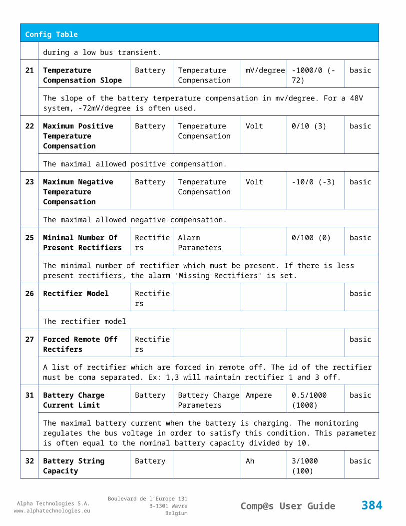
Alpha Technologies S.A.www.alphatechnologies.eu
Alpha Technologies S.A.www.alphatechnologies.eu
Comp@s User GuideBoulevard de l’Europe 131
B-1301 WavreBelgium
Data Table
The number of minute since the last AC Failure begin
14 Minutes Since Last AC Failure End
AC Bus minute basic
The number of minute since the last AC Failure end
21 Rectifiers Output Power Rectifiers Watt basic
The sum of the delivered rectifier power
22 Rectifiers Output Current Rectifiers Ampere basic
The sum of the delivered rectifier current
23 Rectifiers Output Power Max Rectifiers Watt basic
The sum of the deliverable rectifier power
24 Rectifiers Output Current Max Rectifiers Ampere basic
The sum of the deliverable rectifier current
31 Number Of Rectifier Max Rectifiers Numbers basic
The maximum possible number of rectifier in this dc system
32 Number Of Present Rectifier Rectifiers Numbers basic
The actual number of present rectifier in this dc system
33 Number Of Absent Rectifier Rectifiers Numbers basic
The actual number of absent rectifier in this dc system
34 Number Of Active Rectifier Rectifiers Numbers basic
The actual number of active rectifier in this dc system. An active rectifier is a rectifier which is present, DC OK, AC OK and not in remote off.
35 Number Of AC-Fail Rectifier Rectifiers Numbers basic
The actual number or rectifier in AC Failure.
36 Number Of DC-Fail Rectifier Rectifiers Numbers basic
The actual number or rectifier with DC Failure.
37 Number Of Remote Off Rectifier Rectifiers Numbers basic
The actual number or rectifier in remote off.
38 Number Of Over Temperature Rectifier
Rectifiers Numbers basic
384

Alpha Technologies S.A.www.alphatechnologies.eu
Alpha Technologies S.A.www.alphatechnologies.eu
Comp@s User GuideBoulevard de l’Europe 131
B-1301 WavreBelgium
Data Table
The actual number or rectifier in OVer Temperature.
41 Mains Phase 1 Voltage AC Bus Volt basic
The voltage on AC phase 1
42 Mains Phase 2 Voltage AC Bus Volt basic
The voltage on AC phase 2
43 Mains Phase 3 Voltage AC Bus Volt basic
The voltage on AC phase 3
51 Load Power Load Watt basic
Estimation of the load power consumption
52 Load Current Load Ampere basic
Estimation of the load current consumption
61 Battery Input Current Battery Ampere basic
Measurement of the battery input current. A negative value means that the battery is discharging
62 Battery Input Power Battery Watt basic
Measurement of the battery input power. A negative value means that the battery is discharging
71 Battery Temperature Battery Temperature degree C basic
The battery temperature
72 Battery Test State Battery Battery Test basic
This is about the result of the last battery test. 9 values are possible : NEVER_TESTED, SUCCESS, ON_GOING, FAILED_TIMEOUT, FAILED_VBUS_TOO_LOW, FAILED_LOAD_TOO_LOW, FAILED_AC_FAILURE, FAILED_CANCELED, FAILED_LVD_OPENED
73 Battery Test Discharged Capacity Ratio
Battery Battery Test % basic
This is the battery capacity, in percent, discharged during the last battery test. This value is updated at the end of the battery test.
74 Battery Test Discharged Capacity
Battery Battery Test Ah basic
This is the battery capacity, in ampere hour, discharged during the last battery test. This value is updated at the end of the battery test.
75 Battery Test Final Voltage Battery Battery Test % basic
385
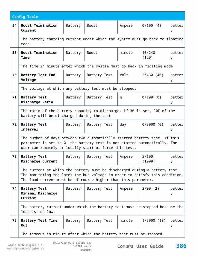
Alpha Technologies S.A.www.alphatechnologies.eu
Alpha Technologies S.A.www.alphatechnologies.eu
Comp@s User GuideBoulevard de l’Europe 131
B-1301 WavreBelgium
Data Table
This is the bus voltage at the end of the last battery test. This value is updated at the end of the battery test.
81 Previous Battery Test State Battery Battery Test basic
The result of the previous battery test
82 Minutes Since Last Test Battery Battery Battery Test basic
The number of minute without battery test
84 Next Scheduled Battery Test Battery Battery Test basic
The date and time of the next time the scheduled battery test will run
91 Battery Charge Capacity Battery % basic
The battery charge capacity, calculated by integration of the current.
92 Calculated Autonomy Battery minute basic
Calculation of the remaining autonomy
93 Battery Current Integration Battery As basic
Actual value of the integration of the current, in Ampere * second
94 Battery Current Integration Battery Ah basic
Actual value of the integration of the current, in Ampere * hour
101
LVD State LVD basic
Actual state of the LVD
111
Relay 1 State Relays Relay 1 basic
Actual state of the Relay 1
112
Relay 2 State Relays Relay 2 basic
Actual state of the Relay 2
113
Relay 3 State Relays Relay 3 basic
Actual state of the Relay 3
114
Relay 4 State Relays Relay 4 basic
Actual state of the Relay 3
121
Efficiency Optimized Number Of Rectifier
Smart Energy asset
386

Alpha Technologies S.A.www.alphatechnologies.eu
Alpha Technologies S.A.www.alphatechnologies.eu
Comp@s User GuideBoulevard de l’Europe 131
B-1301 WavreBelgium
Data Table
The optimal number of ON rectifier for Efficiency Optimization
122
System Loss Without Optimisation
Smart Energy Watt underdev
Estimation of the losses without optimisation
123
System Loss With Optimisation Smart Energy Watt underdev
Estimation of the losses with optimisation
124
Rectifier Model Used For Calculation
Smart Energy asset
The rectifier model used
125
Smart Energy Savings Smart Energy Watt asset
Estimation of the losses with optimisation
151
Ambient Temperature Sensors Temperature degree C basic
The ambiant temperature (second temperature sense)
161
Voltage 1 Sensors Voltage 1 Volt basic
The voltage measured by the sense 1. Can be used for battery symmetry measurement. Calculation can be done with the PLC
162
Voltage 2 Sensors Voltage 2 Volt basic
The voltage measured by the sense 2. Can be used for battery symmetry measurement. Calculation can be done with the PLC
163
Voltage 3 Sensors Voltage 3 Volt basic
The voltage measured by the sense 3. Can be used for battery symmetry measurement. Calculation can be done with the PLC
204
Pulse Counter 4 Sensors Pulse Counter 4 basic
The counter value of the digital input 4.
Config Table
Id Name Group SubGroup Unit Range: Min/Max (default)
License
1 DC Bus Float Voltage at 25 degC
DC Bus Volt 60/120 (108) basic
387

Alpha Technologies S.A.www.alphatechnologies.eu
Alpha Technologies S.A.www.alphatechnologies.eu
Comp@s User GuideBoulevard de l’Europe 131
B-1301 WavreBelgium
Config Table
The floating dc bus voltage of the system at 25 Celsius degree
2 DC Bus Voltage Extra Low
DC Bus Alarm Parameters Volt 60/120 (90) basic
The bus voltage under which the alarm 'DC Bus Voltage Extra Low' is set.
3 DC Bus Voltage Extra Low Hysteresis
DC Bus Alarm Parameters Volt 0/10 (2) basic
The voltage hysteresis on the alarm 'DC Bus Voltage Extra Low'.
4 DC Bus Voltage Low DC Bus Alarm Parameters Volt 60/120 (96) basic
The bus voltage under which the alarm 'DC Bus Voltage Low' is set.
5 DC Bus Voltage Low Hysteresis
DC Bus Alarm Parameters Volt 0/10 (1) basic
The voltage hysteresis on the alarm 'DC Bus Voltage Low
6 DC Bus Voltage High DC Bus Alarm Parameters Volt 60/120 (113) basic
The bus voltage over which the alarm 'DC Bus Voltage High' is set.
7 DC Bus Voltage High Hysteresis
DC Bus Alarm Parameters Volt 0/10 (1) basic
The voltage hysteresis on the alarm 'DC Bus Voltage High
8 DC Bus Voltage Extra High
DC Bus Alarm Parameters Volt 60/120 (116) basic
The bus voltage over which the alarm 'DC Bus Voltage Extra High' is set.
9 DC Bus Voltage Extra High Hysteresis
DC Bus Alarm Parameters Volt 0/10 (1) basic
The voltage hysteresis on the alarm 'DC Bus Voltage Extra High
10 LVD Disconnect Voltage LVD Volt 0/100 (86.4) basic
The dc bus voltage under which the battery must be disconnected of the bus. This allows preserving the battery life. The load will be unpowered.
11 LVD Disconnect Delay LVD second 1/4000 (1) basic
The delay in second before disconnecting the battery if the dc bus voltage is under the configured disconnected voltage. This avoids disconnection during a low bus transient.
21 Temperature Compensation Slope
Battery Temperature Compensation
mV/degree -2000/0 (-144) basic
The slope of the battery temperature compensation in mv/degree. For a 48V system, -72mV/degree is
388

Alpha Technologies S.A.www.alphatechnologies.eu
Alpha Technologies S.A.www.alphatechnologies.eu
Comp@s User GuideBoulevard de l’Europe 131
B-1301 WavreBelgium
Config Table
often used.
22 Maximum Positive Temperature Compensation
Battery Temperature Compensation
Volt 0/20 (6) basic
The maximal allowed positive compensation.
23 Maximum Negative Temperature Compensation
Battery Temperature Compensation
Volt -20/0 (-6) basic
The maximal allowed negative compensation.
25 Minimal Number Of Present Rectifiers
Rectifiers Alarm Parameters 0/100 (0) basic
The minimal number of rectifier which must be present. If there is less present rectifiers, the alarm 'Missing Rectifiers' is set.
26 Rectifier Model Rectifiers basic
The rectifier model
27 Forced Remote Off Rectifers
Rectifiers basic
A list of rectifier which are forced in remote off. The id of the rectifier must be coma separated. Ex: 1,3 will maintain rectifier 1 and 3 off.
31 Battery Charge Current Limit
Battery Battery Charge Parameters
Ampere 0.5/1000 (1000) basic
The maximal battery current when the battery is charging. The monitoring regulates the bus voltage in order to satisfy this condition. This parameter is often equal to the nominal battery capacity divided by 10.
32 Battery String Capacity Battery Ah 3/1000 (100) basic
The battery capacity in Ah.
33 Battery Temperature Low
Battery Alarm Parameters degree C -100/20 (0) basic
The temperature under which the alarm 'Battery Temperature Too Low' must be set.
34 Battery Temperature High
Battery Alarm Parameters degree C 5/100 (40) basic
The temperature over which the alarm 'Battery Temperature Too High' must be set.
35 Battery Temperature Hysteresis
Battery Alarm Parameters degree C 0/10 (2) basic
389
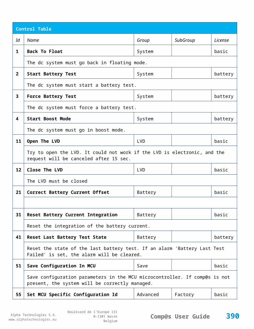
Alpha Technologies S.A.www.alphatechnologies.eu
Alpha Technologies S.A.www.alphatechnologies.eu
Comp@s User GuideBoulevard de l’Europe 131
B-1301 WavreBelgium
Config Table
The hysteresis on the 'Battery Temperature Too High' and 'Battery Temperature Too Low' alarms.
36 Minimal Current For Discharging Alarm
Battery Alarm Parameters Ampere 0/1000 (3) basic
The minimal discharging current to set the 'Battery On Discharge' alarm.
37 Current Hysteresis For Discharging Alarm
Battery Alarm Parameters Ampere 0/50 (1) basic
The hysteresis on the 'Battery On Discharge' alarm.
41 Shunt Rating At 60mV Current Sensors
Shunt 1 Ampere 25/5000 (250) basic
The rating of the battery shunt at 60mV.
51 Boost Automatic Battery Boost False/False (False)
battery
The boost mode must be automatically after the fact that during a mains failure, the bus voltage went under the configured 'Boost Activation Low Voltage'. This allows charging the battery faster.
52 Boost Activation Low Voltage
Battery Boost Volt 86/100 (92) battery
The voltage under which the boost mode can be activated.
53 Boost Termination Voltage
Battery Boost Volt 100/116 (112.8) battery
The voltage over which the system must go back to floating mode.
54 Boost Termination Current
Battery Boost Ampere 0/100 (4) battery
The battery charging current under which the system must go back to floating mode.
55 Boost Termination Time Battery Boost minute 10/240 (120) battery
The time in minute after which the system must go back in floating mode.
70 Battery Test End Voltage
Battery Battery Test Volt 60/120 (92) battery
The voltage at which any battery test must be stopped.
71 Battery Test Discharge Ratio
Battery Battery Test % 0/100 (0) battery
The ratio of the battery capacity to discharge. If 30 is set, 30% of the battery will be discharged during the test
72 Battery Test Interval Battery Battery Test day 0/3000 (0) battery
390

Alpha Technologies S.A.www.alphatechnologies.eu
Alpha Technologies S.A.www.alphatechnologies.eu
Comp@s User GuideBoulevard de l’Europe 131
B-1301 WavreBelgium
Config Table
The number of days between two automatically started battery test. If this parameter is set to 0, the battery test is not started automatically. The user can remotely or locally start or force this test.
73 Battery Test Discharge Current
Battery Battery Test Ampere 10/5000 (2000) battery
The current at which the battery must be discharged during a battery test. The monitoring regulates the bus voltage in order to satisfy this condition. The load current must be of course higher than this parameter.
74 Battery Test Minimal Discharge Current
Battery Battery Test Ampere 2/90 (2) battery
The battery current under which the battery test must be stopped because the load is too low.
75 Battery Test Time Out Battery Battery Test minute 1/5000 (10) battery
The timeout in minute after which the battery test must be stopped.
76 Battery Test Requested Minutes Without Mains Failure
Battery Battery Test minute 0/5000 (1440) battery
The minimal time in minute without mains failure in order to allow a battery start. This parameter is not taken into account when the battery test is forced.
77 Battery Test Scheduler Cron Rule
Battery Battery Test basic
83 Smart Energy Boolean Condition
Smart Energy
asset
This is the boolean condition which allows or not to automatically optimize the number of rectifier in remote off.
86 Battery LVD Node Id LVD True/False (False)
basic
This is a list of the node id of the Smart Electronic LVDs, coma separated
91 Digital Input 1 Name Digital Inputs
Digital Input 1 Distribution Breaker Open
basic
The name of the digital input 1
92 Digital Input 1 Normally Closed
Digital Inputs
Digital Input 1 True/False (True)
basic
True/False value defining if the digital input 1 is normally closed. If this digital input is not in this default state, the related alarm is set.
93 Digital Input 2 Name Digital Digital Input 2 Battery Breaker basic
391

Alpha Technologies S.A.www.alphatechnologies.eu
Alpha Technologies S.A.www.alphatechnologies.eu
Comp@s User GuideBoulevard de l’Europe 131
B-1301 WavreBelgium
Config Table
Inputs Open
The name of the digital input 2
94 Digital Input 2 Normally Closed
Digital Inputs
Digital Input 2 True/False (True)
basic
True/False value defining if the digital input 2 is normally closed. If this digital input is not in this default state, the related alarm is set.
95 Digital Input 3 Name Digital Inputs
Digital Input 3 Digital Input 3 basic
The name of the digital input 3
96 Digital Input 3 Normally Closed
Digital Inputs
Digital Input 3 True/False (True)
basic
True/False value defining if the digital input 3 is normally closed. If this digital input is not in this default state, the related alarm is set.
97 Digital Input 4 Name Digital Inputs
Digital Input 4 Digital Input 4 basic
The name of the digital input 4
98 Digital Input 4 Normally Closed
Digital Inputs
Digital Input 4 True/False (True)
basic
True/False value defining if the digital input 4 is normally closed. If this digital input is not in this default state, the related alarm is set.
99 Digital Input 5 Name Digital Inputs
Digital Input 5 Digital Input 5 basic
The name of the digital input 5
100
Digital Input 5 Normally Closed
Digital Inputs
Digital Input 5 True/False (True)
basic
True/False value defining if the digital input 5 is normally closed. If this digital input is not in this default state, the related alarm is set.
101
Digital Input 6 Name Digital Inputs
Digital Input 6 Digital Input 6 basic
The name of the digital input 6
102
Digital Input 6 Normally Closed
Digital Inputs
Digital Input 6 True/False (True)
basic
True/False value defining if the digital input 6 is normally closed. If this digital input is not in this default state, the related alarm is set.
392

Alpha Technologies S.A.www.alphatechnologies.eu
Alpha Technologies S.A.www.alphatechnologies.eu
Comp@s User GuideBoulevard de l’Europe 131
B-1301 WavreBelgium
Config Table
103
Digital Input 7 Name Digital Inputs
Digital Input 7 Digital Input 7 basic
The name of the digital input 7
104
Digital Input 7 Normally Closed
Digital Inputs
Digital Input 7 True/False (True)
basic
True/False value defining if the digital input 7 is normally closed. If this digital input is not in this default state, the related alarm is set.
105
Digital Input 8 Name Digital Inputs
Digital Input 8 Digital Input 8 basic
The name of the digital input 8
106
Digital Input 8 Normally Closed
Digital Inputs
Digital Input 8 True/False (True)
basic
True/False value defining if the digital input 8 is normally closed. If this digital input is not in this default state, the related alarm is set.
111
Dry Alarm 1 Alternative Boolean Condition
Relays Relay 1 plc
Another Boolean condition to activate the dry alarm relay 1. The way to define boolean condition is detailed in the PLC chapter.
112
Dry Alarm 2 Alternative Boolean Condition
Relays Relay 2 plc
Another Boolean condition to activate the dry alarm relay 2. The way to define boolean condition is detailed in the PLC chapter.
113
Dry Alarm 3 Alternative Boolean Condition
Relays Relay 3 plc
Another Boolean condition to activate the dry alarm relay 3. The way to define boolean condition is detailed in the PLC chapter.
114
Dry Alarm 4 Alternative Boolean Condition
Relays Relay 4 plc
Another Boolean condition to activate the dry alarm relay 4. The way to define boolean condition is detailed in the PLC chapter.
131
Ambient Temperature Low
Sensors Temperature degree C basic
The temperature under which the alarm 'Ambiant Temperature Too Low' must be set.
132
Ambient Temperature High
Sensors Temperature degree C basic
393

Alpha Technologies S.A.www.alphatechnologies.eu
Alpha Technologies S.A.www.alphatechnologies.eu
Comp@s User GuideBoulevard de l’Europe 131
B-1301 WavreBelgium
Config Table
The temperature under which the alarm 'Ambiant Temperature Too Low' must be set.
133
Ambient Temperature Hysteresis
Sensors Temperature degree C basic
The hysteresis on the 'Battery Temperature Too High' and 'Battery Temperature Too Low' alarms.
141
AC Voltage Low Mains Volt 0/240 (180) basic
The AC voltage under which the alarm AC Low is set.
142
AC Voltage High Mains Volt 80/600 (250) basic
The AC voltage over which the alarm AC High is set.
143
AC Voltage Hysteresis Mains Volt 0/40 (5) basic
The AC voltage hysteresis on alarms AC High and AC Low.
144
AC Phase 1 PLC AC Bus basic
This is the mathematical expression of the calculation of AC phase 1. If empty, the rectifiers are used. The syntax for writting mathematical expression is described in the PLC chapter. The PLC data element is the result of the calculation.
145
AC Phase 2 PLC AC Bus basic
This is the mathematical expression of the calculation of AC phase 2. If empty, the rectifiers are used. The syntax for writting mathematical expression is described in the PLC chapter. The PLC data element is the result of the calculation.
146
AC Phase 3 PLC AC Bus basic
This is the mathematical expression of the calculation of AC phase 3. If empty, the rectifiers are used. The syntax for writting mathematical expression is described in the PLC chapter. The PLC data element is the result of the calculation.
521
Read Access User Numbers
Generic Allowed Users (1,2,3,4,5) basic
The list of the user numbers which have read access to this equipment. The user numbers are coma separated. The accepted user id are 1,2,3,4 and 5. Ex: 1,3,4
522
Write Access User Numbers
Generic Allowed Users () basic
The list of the user numbers which have write access to this equipment. This means that these users can modify the configuration element, the alarm settings and use the control elements. The user numbers are coma separated. The accepted user ids are 1,2,3,4 and 5. Ex: 1,3,4
601
Event Table Length Generic Events 10/4000 (100) basic
The maximum length of the table. The value must be comprised between 10 and 4000
394

Alpha Technologies S.A.www.alphatechnologies.eu
Alpha Technologies S.A.www.alphatechnologies.eu
Comp@s User GuideBoulevard de l’Europe 131
B-1301 WavreBelgium
Config Table
602
Event Table Length By Rectifier
Generic Events 10/4000 (100) basic
The maximum length of the table. The value must be comprised between 10 and 4000
901
Number Of PLC Data PLC (0) plc
The number of PLC data. Every equipment can manage up to 20 user programmable data. Data elements are automatically added in the data table. Configuration parameters are added to set the PLC Data Name and the PLC Data Mathematical calculation. In order to use these functionalities, you need a license with the 'PLC' module
902
Number Of PLC Alarm PLC (0) plc
The number of PLC alarm. Every equipment can manage up to 20 user programmable alarms. Alarm elements are automatically added in the alarm table. The alarm parameters are added to set the PLC Alarm Name and the PLC Alarm Boolean condition. In order to use these functionalities, you need a licence with the 'PLC' module
Control Table
Id Name Group SubGroup License
1 Back To Float System basic
The dc system must go back in floating mode.
2 Start Battery Test System battery
The dc system must start a battery test.
3 Force Battery Test System battery
The dc system must force a battery test.
4 Start Boost Mode System battery
The dc system must go in boost mode.
11 Open The LVD LVD basic
Try to open the LVD. It could not work if the LVD is electronic, and the request will be canceled after 15 sec.
12 Close The LVD LVD basic
The LVD must be closed
21 Correct Battery Current Offset Battery basic
395

Alpha Technologies S.A.www.alphatechnologies.eu
Alpha Technologies S.A.www.alphatechnologies.eu
Comp@s User GuideBoulevard de l’Europe 131
B-1301 WavreBelgium
Control Table
31 Reset Battery Current Integration Battery basic
Reset the integration of the battery current.
41 Reset Last Battery Test State Battery battery
Reset the state of the last battery test. If an alarm 'Battery Last Test Failed' is set, the alarm will be cleared.
51 Save Configuration In MCU Save basic
Save configuration parameters in the MCU microcontroller. If comp@s is not present, the system will be correctly managed.
55 Set MCU Specific Configuration Id Advanced Factory basic
This control allows to reconfigure the MCU to support specific hardware configuration, with embedded distribution for example
61 Set Digital Input 4 Counter Value Digital Inputs Digital Input 4 basic
Set Counter Value
111
Invert Relay 1 State For X Seconds Relays Relay 1 basic
Generate Pulse on relay 1
112
Invert Relay 2 State For X Seconds Relays Relay 2 basic
Generate Pulse on relay 2
113
Invert Relay 3 State For X Seconds Relays Relay 3 basic
Generate Pulse on relay 3
114
Invert Relay 4 State For X Seconds Relays Relay 4 basic
Generate Pulse on relay 4
501
Clear My Events Generic Events basic
By writing '1' to this control element, all the events of this equipment will be cleared.
502
Clear All Events Generic Events basic
By writing '1' to this control element, all the events of this equipment and all the events of all the sub-equipments will be cleared.
511
Add Event Generic Events basic
This control element adds an event of severity none. The event name is the text written to this control element
51 Add Major Event Generic Events basic
396

Alpha Technologies S.A.www.alphatechnologies.eu
Alpha Technologies S.A.www.alphatechnologies.eu
Comp@s User GuideBoulevard de l’Europe 131
B-1301 WavreBelgium
Control Table
2 This control element adds an event of severity major. The event name is the text written to this control element
521
Reset Default Names And Groups Generic Renaming basic
This control element resets all the element Names, Groups and Subgroups to default values for this equipment
522
Reset Default Names And Groups Recursive Generic Renaming basic
This control element resets all the element Names, Groups and Subgroups to default values for this equipment and all sub equipments
7.2.17 MCU30125M6
Device Information
Name MCU30125M6
Short Description MCU for rack 6x3000W +125V
Long Description
Hardware Reference 9413 000 XXXX
Software Reference SOFT 000057 XX
Equipment Type Monitoring Control Unit
ETSI Level /site/energy_system/dc_system
Description Table
Id Name Group SubGroup License
1 Description Description Custom Description basic
A free text zone to write a system description
2 Reference Description Custom Description basic
A free text zone to write the customer reference of the system
11 Product Name Description Product Info basic
The product name of the DC system monitoring
12 Hardware Reference Description Product Info basic
The hardware reference of the DC system monitoring
397
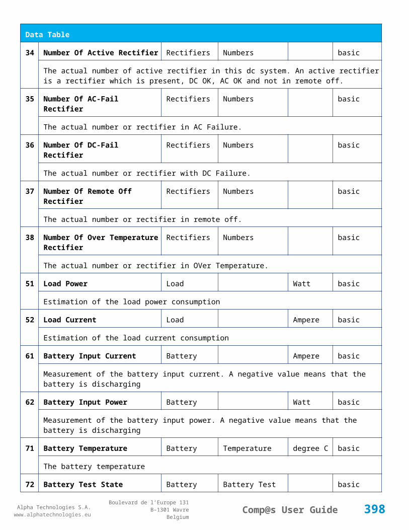
Alpha Technologies S.A.www.alphatechnologies.eu
Alpha Technologies S.A.www.alphatechnologies.eu
Comp@s User GuideBoulevard de l’Europe 131
B-1301 WavreBelgium
Description Table
14 Software Reference Description Product Info asset
The serial number of the DC system monitoring
16 Serial Number Description Product Info asset
The serial number of the DC system monitoring
18 Manufacturing Date Description Product Info asset
The production date of the DC system monitoring
Alarm Table
Id Name Group SubGroup Severity Type (Level)
Set/Clear Delay
1 DC Bus Extra Low DC Bus major (6) 5 / 2
The bus voltage is extra low. The alarm is set when the bus voltage is lower than the configuration parameter 'DC Bus Voltage Extra Low'. There is an hysteresis on the alarm : 'DC Bus Voltage Extra Low Hysteresis'. The alarm is not activated when DC mode is BATTERY TEST
2 DC Bus Low DC Bus minor (4) 5 / 2
The bus voltage is low. The alarm is set when the bus voltage is lower than the configuration parameter 'DC Bus Voltage Low'. There is an hysteresis on the alarm : 'DC Bus Voltage Low Hysteresis'
3 DC Bus High DC Bus minor (4) 5 / 2
The bus voltage is high. The alarm is set when the bus voltage is higher than the configuration paramenter 'DC Bus Voltage High'. There is an hysterisis on the alarm : 'DC Bus Voltage High Hysteresis'
4 DC Bus Extra High DC Bus major (6) 5 / 2
The bus voltage is extra high. The alarm is set when the bus voltage is higher than the configuration paramenter 'DC Bus Voltage Extra High'. There is an hysterisis on the alarm : 'DC Bus Voltage Extra High Hysteresis'
5 DC Bus Voltage Sense Failure
DC Bus major (6) 5 / 2
The DC bus voltage sense is defective. The DC bus voltage is unconnected or unconfigured.
6 Mains Failure AC Bus minor (4) 5 / 2
The number of active rectifiers is equal to 0 and the number of rectifiers in AC failure is greater than 0.
7 Mains Partial Failure AC Bus minor (4) 10 / 2
The number of active rectifiers is greater than 0 and the number of rectifiers in AC failure is greater than
398

Alpha Technologies S.A.www.alphatechnologies.eu
Alpha Technologies S.A.www.alphatechnologies.eu
Comp@s User GuideBoulevard de l’Europe 131
B-1301 WavreBelgium
Alarm Table
0. Some rectifiers are in AC Failure. It may be caused by an open breaker, a real phase failure, or by a rectifier failure.
8 Mains Low AC Bus warning (2) 10 / 2
The main voltage is low on one or more phases. No rectifier is in AC failure. If MCU master type is 30110, 3096 or 3048M6, an hysteresis _phase123Hysteresis is added to the voltage lower limit
10
One Rectifier Failure Rectifiers minor (4) 5 / 2
One rectifier must be replaced or is not powered correctly. The DC fail alarm of the rectifier is set. The number of rectifier with DC Failure is higher than 0, there is no mains failure, and the 'More Than One Rectifier Failure alarm is not set.'
11
More Than One Rectifier Failure
Rectifiers major (6) 10 / 2
There is no mains failure and number of rectifier failures is greater than 1.
12
Missing Rectifiers Rectifiers major (6) 5 / 2
There is not enough rectifier according to the configuration parameter : 'Minimal Number Of Rectifier'
13
Battery Last Test Failed Battery Battery Test minor (3) 5 / 2
The last battery test did not succeed and was not cancelled. Maybe the battery should be replaced.
14
Battery On Discharge Battery minor (4) 10 / 2
The battery is discharging. This means that the load is too high for the installed rectifiers. This alarm is inactive when the system in AC Failure or during a battery test. There is an hysteresis corresponding to battery parameter 'Is discharging current hysteresis'.
17
Battery LVD Relay Open LVD major (6) 5 / 2
The battery Low Voltage Disconnector is open. On Systems without LVD_Status signal, like MCU 1848 or MCU 1x6, the alarm is present only if the signal LVD_COM asks to open the LVD
18
Battery Temperature Too High
Battery Temperature minor (3) 5 / 2
The temperature of the battery is too high and is greater than -600 units. There is an hysteresis corresponding to battery parameter 'Temperature hysteresis'.
19
Battery Temperature Too Low
Battery Temperature minor (3) 5 / 2
The temperature of the battery is too low and is greater than -600 units. There is an hysteresis corresponding to battery parameter 'Temperature hysteresis'.
20
Battery Temperature Sensor Fail
Battery Temperature minor (3) 5 / 2
The battery temperature sensor (NTC) value is inferior to -500 units meaning that it is not connected or
399

Alpha Technologies S.A.www.alphatechnologies.eu
Alpha Technologies S.A.www.alphatechnologies.eu
Comp@s User GuideBoulevard de l’Europe 131
B-1301 WavreBelgium
Alarm Table
defective.
21
Ambient Temperature Too High
Sensors Temperature minor (0) 5 / 2
The ambient temperature is too high and is greater than -600 units. There is an hysteresis corresponding to parameter 'Ambiant temperature hysteresis'. This alarm is only activated on MCU master types 30110, 3096, 30125, 0024, 0948, 0548, 0348, 0948 and 3048M6.
22
Ambient Temperature Too Low
Sensors Temperature minor (0) 5 / 2
The ambient temperature is too low and is greater than -600 units. There is an hysteresis corresponding to parameter 'Ambiant temperature hysteresis'. This alarm is only activated on MCU master types 30110, 3096, 30125, 0024, 0948, 0548, 0348, 0948 and 3048M6.
23
Ambient Temperature Sensor Fail
Sensors Temperature minor (0) 5 / 2
The ambiant temperature sensor (NTC) value is inferior to -500 units meaning that it is not connected or defective.
25
Distribution Breaker Open Digital Inputs major (6) 5 / 2
This alarm is related to digital input 1. This alarm is activated if digital input value is different to configuration parameter 'Digital Input Alarm Value'
26
Battery Breaker Open Digital Inputs minor (4) 5 / 2
This alarm is related to digital input 2. This alarm is activated if digital input value is different to configuration parameter 'Digital Input Alarm Value'
27
Digital Input 3 Digital Inputs none (0) 5 / 2
This alarm is related to digital input 3. This alarm is activated if digital input value is different to configuration parameter 'Digital Input Alarm Value'
28
Digital Input 4 Digital Inputs none (0) 5 / 2
This alarm is related to digital input 4. This alarm is activated if digital input value is different to configuration parameter 'Digital Input Alarm Value'
29
Digital Input 5 Digital Inputs none (0) 5 / 2
This alarm is related to digital input 5. This alarm is activated if digital input value is different to configuration parameter 'Digital Input Alarm Value'
30
Digital Input 6 Digital Inputs none (0) 5 / 2
This alarm is related to digital input 6. This alarm is activated if digital input value is different to configuration parameter 'Digital Input Alarm Value'
3 Digital Input 7 Digital Inputs none (0) 5 / 2
400

Alpha Technologies S.A.www.alphatechnologies.eu
Alpha Technologies S.A.www.alphatechnologies.eu
Comp@s User GuideBoulevard de l’Europe 131
B-1301 WavreBelgium
Alarm Table
1 This alarm is related to digital input 7. This alarm is activated if digital input value is different to configuration parameter 'Digital Input Alarm Value'
32
Digital Input 8 Digital Inputs none (0) 5 / 2
This alarm is related to digital input 8. This alarm is activated if digital input value is different to configuration parameter 'Digital Input Alarm Value'
Data Table
Id Name Group SubGroup Unit License
1 DC Mode System basic
The DC system can have 4 values: 'FLOAT', 'BOOST', 'BATTERY_TEST', 'AC_FAILURE' or SAFE
2 Previous DC Mode System basic
The previous value of the DC Mode
11 Bus Voltage DC Bus Volt basic
The DC bus voltage in volt.
12 Ratio Delivered On Available Power
System % basic
This is the ratio of the delivered power divided by the installed power, in %.
13 Minutes Since Last AC Failure Begin
AC Bus minute basic
The number of minute since the last AC Failure begin
14 Minutes Since Last AC Failure End
AC Bus minute basic
The number of minute since the last AC Failure end
21 Rectifiers Output Power Rectifiers Watt basic
The sum of the delivered rectifier power
22 Rectifiers Output Current Rectifiers Ampere basic
The sum of the delivered rectifier current
23 Rectifiers Output Power Max Rectifiers Watt basic
The sum of the deliverable rectifier power
24 Rectifiers Output Current Max Rectifiers Ampere basic
401
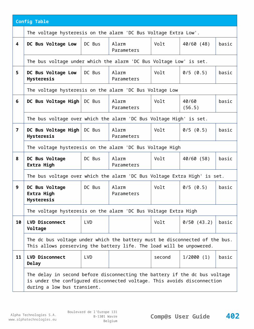
Alpha Technologies S.A.www.alphatechnologies.eu
Alpha Technologies S.A.www.alphatechnologies.eu
Comp@s User GuideBoulevard de l’Europe 131
B-1301 WavreBelgium
Data Table
The sum of the deliverable rectifier current
31 Number Of Rectifier Max Rectifiers Numbers basic
The maximum possible number of rectifier in this dc system
32 Number Of Present Rectifier Rectifiers Numbers basic
The actual number of present rectifier in this dc system
33 Number Of Absent Rectifier Rectifiers Numbers basic
The actual number of absent rectifier in this dc system
34 Number Of Active Rectifier Rectifiers Numbers basic
The actual number of active rectifier in this dc system. An active rectifier is a rectifier which is present, DC OK, AC OK and not in remote off.
35 Number Of AC-Fail Rectifier Rectifiers Numbers basic
The actual number or rectifier in AC Failure.
36 Number Of DC-Fail Rectifier Rectifiers Numbers basic
The actual number or rectifier with DC Failure.
37 Number Of Remote Off Rectifier Rectifiers Numbers basic
The actual number or rectifier in remote off.
38 Number Of Over Temperature Rectifier
Rectifiers Numbers basic
The actual number or rectifier in OVer Temperature.
41 Mains Phase 1 Voltage AC Bus Volt basic
The voltage on AC phase 1
42 Mains Phase 2 Voltage AC Bus Volt basic
The voltage on AC phase 2
43 Mains Phase 3 Voltage AC Bus Volt basic
The voltage on AC phase 3
51 Load Power Load Watt basic
Estimation of the load power consumption
52 Load Current Load Ampere basic
402

Alpha Technologies S.A.www.alphatechnologies.eu
Alpha Technologies S.A.www.alphatechnologies.eu
Comp@s User GuideBoulevard de l’Europe 131
B-1301 WavreBelgium
Data Table
Estimation of the load current consumption
61 Battery Input Current Battery Ampere basic
Measurement of the battery input current. A negative value means that the battery is discharging
62 Battery Input Power Battery Watt basic
Measurement of the battery input power. A negative value means that the battery is discharging
71 Battery Temperature Battery Temperature degree C basic
The battery temperature
72 Battery Test State Battery Battery Test basic
This is about the result of the last battery test. 9 values are possible : NEVER_TESTED, SUCCESS, ON_GOING, FAILED_TIMEOUT, FAILED_VBUS_TOO_LOW, FAILED_LOAD_TOO_LOW, FAILED_AC_FAILURE, FAILED_CANCELED, FAILED_LVD_OPENED
73 Battery Test Discharged Capacity Ratio
Battery Battery Test % basic
This is the battery capacity, in percent, discharged during the last battery test. This value is updated at the end of the battery test.
74 Battery Test Discharged Capacity
Battery Battery Test Ah basic
This is the battery capacity, in ampere hour, discharged during the last battery test. This value is updated at the end of the battery test.
75 Battery Test Final Voltage Battery Battery Test % basic
This is the bus voltage at the end of the last battery test. This value is updated at the end of the battery test.
81 Previous Battery Test State Battery Battery Test basic
The result of the previous battery test
82 Minutes Since Last Test Battery Battery Battery Test basic
The number of minute without battery test
84 Next Scheduled Battery Test Battery Battery Test basic
The date and time of the next time the scheduled battery test will run
91 Battery Charge Capacity Battery % basic
The battery charge capacity, calculated by integration of the current.
92 Calculated Autonomy Battery minute basic
403
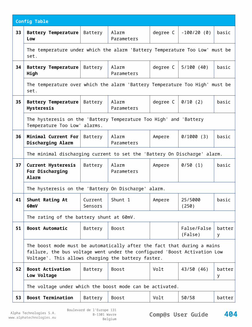
Alpha Technologies S.A.www.alphatechnologies.eu
Alpha Technologies S.A.www.alphatechnologies.eu
Comp@s User GuideBoulevard de l’Europe 131
B-1301 WavreBelgium
Data Table
Calculation of the remaining autonomy
93 Battery Current Integration Battery As basic
Actual value of the integration of the current, in Ampere * second
94 Battery Current Integration Battery Ah basic
Actual value of the integration of the current, in Ampere * hour
101
LVD State LVD basic
Actual state of the LVD
111
Relay 1 State Relays Relay 1 basic
Actual state of the Relay 1
112
Relay 2 State Relays Relay 2 basic
Actual state of the Relay 2
113
Relay 3 State Relays Relay 3 basic
Actual state of the Relay 3
114
Relay 4 State Relays Relay 4 basic
Actual state of the Relay 3
121
Efficiency Optimized Number Of Rectifier
Smart Energy asset
The optimal number of ON rectifier for Efficiency Optimization
122
System Loss Without Optimisation
Smart Energy Watt underdev
Estimation of the losses without optimisation
123
System Loss With Optimisation Smart Energy Watt underdev
Estimation of the losses with optimisation
124
Rectifier Model Used For Calculation
Smart Energy asset
The rectifier model used
125
Smart Energy Savings Smart Energy Watt asset
Estimation of the losses with optimisation
15 Ambient Temperature Sensors Temperature degree C basic
404

Alpha Technologies S.A.www.alphatechnologies.eu
Alpha Technologies S.A.www.alphatechnologies.eu
Comp@s User GuideBoulevard de l’Europe 131
B-1301 WavreBelgium
Data Table
1 The ambiant temperature (second temperature sense)
161
Voltage 1 Sensors Voltage 1 Volt basic
The voltage measured by the sense 1. Can be used for battery symmetry measurement. Calculation can be done with the PLC
162
Voltage 2 Sensors Voltage 2 Volt basic
The voltage measured by the sense 2. Can be used for battery symmetry measurement. Calculation can be done with the PLC
163
Voltage 3 Sensors Voltage 3 Volt basic
The voltage measured by the sense 3. Can be used for battery symmetry measurement. Calculation can be done with the PLC
204
Pulse Counter 4 Sensors Pulse Counter 4 basic
The counter value of the digital input 4.
Config Table
Id Name Group SubGroup Unit Range: Min/Max (default)
License
1 DC Bus Float Voltage at 25 degC
DC Bus Volt 92/138 (125) basic
The floating dc bus voltage of the system at 25 Celsius degree
2 DC Bus Voltage Extra Low
DC Bus Alarm Parameters Volt 92/138 (103.5) basic
The bus voltage under which the alarm 'DC Bus Voltage Extra Low' is set.
3 DC Bus Voltage Extra Low Hysteresis
DC Bus Alarm Parameters Volt 0/10 (2) basic
The voltage hysteresis on the alarm 'DC Bus Voltage Extra Low'.
4 DC Bus Voltage Low DC Bus Alarm Parameters Volt 92/138 (110.4) basic
The bus voltage under which the alarm 'DC Bus Voltage Low' is set.
5 DC Bus Voltage Low Hysteresis
DC Bus Alarm Parameters Volt 0/10 (1) basic
The voltage hysteresis on the alarm 'DC Bus Voltage Low
6 DC Bus Voltage High DC Bus Alarm Parameters Volt 92/138 (129.95) basic
405

Alpha Technologies S.A.www.alphatechnologies.eu
Alpha Technologies S.A.www.alphatechnologies.eu
Comp@s User GuideBoulevard de l’Europe 131
B-1301 WavreBelgium
Config Table
The bus voltage over which the alarm 'DC Bus Voltage High' is set.
7 DC Bus Voltage High Hysteresis
DC Bus Alarm Parameters Volt 0/10 (1) basic
The voltage hysteresis on the alarm 'DC Bus Voltage High
8 DC Bus Voltage Extra High
DC Bus Alarm Parameters Volt 92/138 (133.4) basic
The bus voltage over which the alarm 'DC Bus Voltage Extra High' is set.
9 DC Bus Voltage Extra High Hysteresis
DC Bus Alarm Parameters Volt 0/10 (1) basic
The voltage hysteresis on the alarm 'DC Bus Voltage Extra High
10 LVD Disconnect Voltage LVD Volt 0/115 (99.36) basic
The dc bus voltage under which the battery must be disconnected of the bus. This allows preserving the battery life. The load will be unpowered.
11 LVD Disconnect Delay LVD second 1/4000 (1) basic
The delay in second before disconnecting the battery if the dc bus voltage is under the configured disconnected voltage. This avoids disconnection during a low bus transient.
21 Temperature Compensation Slope
Battery Temperature Compensation
mV/degree -2000/0 (-165) basic
The slope of the battery temperature compensation in mv/degree. For a 48V system, -72mV/degree is often used.
22 Maximum Positive Temperature Compensation
Battery Temperature Compensation
Volt 0/20 (6) basic
The maximal allowed positive compensation.
23 Maximum Negative Temperature Compensation
Battery Temperature Compensation
Volt -20/0 (-6) basic
The maximal allowed negative compensation.
25 Minimal Number Of Present Rectifiers
Rectifiers Alarm Parameters 0/100 (0) basic
The minimal number of rectifier which must be present. If there is less present rectifiers, the alarm 'Missing Rectifiers' is set.
26 Rectifier Model Rectifiers basic
The rectifier model
406
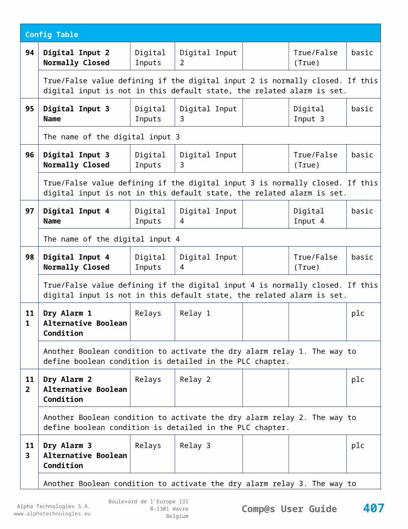
Alpha Technologies S.A.www.alphatechnologies.eu
Alpha Technologies S.A.www.alphatechnologies.eu
Comp@s User GuideBoulevard de l’Europe 131
B-1301 WavreBelgium
Config Table
27 Forced Remote Off Rectifers
Rectifiers basic
A list of rectifier which are forced in remote off. The id of the rectifier must be coma separated. Ex: 1,3 will maintain rectifier 1 and 3 off.
31 Battery Charge Current Limit
Battery Battery Charge Parameters
Ampere 0.5/1000 (1000) basic
The maximal battery current when the battery is charging. The monitoring regulates the bus voltage in order to satisfy this condition. This parameter is often equal to the nominal battery capacity divided by 10.
32 Battery String Capacity Battery Ah 3/1000 (100) basic
The battery capacity in Ah.
33 Battery Temperature Low
Battery Alarm Parameters degree C -100/20 (0) basic
The temperature under which the alarm 'Battery Temperature Too Low' must be set.
34 Battery Temperature High
Battery Alarm Parameters degree C 5/100 (40) basic
The temperature over which the alarm 'Battery Temperature Too High' must be set.
35 Battery Temperature Hysteresis
Battery Alarm Parameters degree C 0/10 (2) basic
The hysteresis on the 'Battery Temperature Too High' and 'Battery Temperature Too Low' alarms.
36 Minimal Current For Discharging Alarm
Battery Alarm Parameters Ampere 0/1000 (3) basic
The minimal discharging current to set the 'Battery On Discharge' alarm.
37 Current Hysteresis For Discharging Alarm
Battery Alarm Parameters Ampere 0/50 (1) basic
The hysteresis on the 'Battery On Discharge' alarm.
41 Shunt Rating At 60mV Current Sensors
Shunt 1 Ampere 25/5000 (250) basic
The rating of the battery shunt at 60mV.
51 Boost Automatic Battery Boost False/False (False)
battery
The boost mode must be automatically after the fact that during a mains failure, the bus voltage went under the configured 'Boost Activation Low Voltage'. This allows charging the battery faster.
52 Boost Activation Low Battery Boost Volt 86/100 (92) battery
407

Alpha Technologies S.A.www.alphatechnologies.eu
Alpha Technologies S.A.www.alphatechnologies.eu
Comp@s User GuideBoulevard de l’Europe 131
B-1301 WavreBelgium
Config Table
Voltage
The voltage under which the boost mode can be activated.
53 Boost Termination Voltage
Battery Boost Volt 115/133.4 (129.72)
battery
The voltage over which the system must go back to floating mode.
54 Boost Termination Current
Battery Boost Ampere 0/100 (4) battery
The battery charging current under which the system must go back to floating mode.
55 Boost Termination Time Battery Boost minute 10/240 (120) battery
The time in minute after which the system must go back in floating mode.
70 Battery Test End Voltage
Battery Battery Test Volt 69/138 (105.8) battery
The voltage at which any battery test must be stopped.
71 Battery Test Discharge Ratio
Battery Battery Test % 0/100 (0) battery
The ratio of the battery capacity to discharge. If 30 is set, 30% of the battery will be discharged during the test
72 Battery Test Interval Battery Battery Test day 0/3000 (0) battery
The number of days between two automatically started battery test. If this parameter is set to 0, the battery test is not started automatically. The user can remotely or locally start or force this test.
73 Battery Test Discharge Current
Battery Battery Test Ampere 3/100 (1000) battery
The current at which the battery must be discharged during a battery test. The monitoring regulates the bus voltage in order to satisfy this condition. The load current must be of course higher than this parameter.
74 Battery Test Minimal Discharge Current
Battery Battery Test Ampere 2/90 (2) battery
The battery current under which the battery test must be stopped because the load is too low.
75 Battery Test Time Out Battery Battery Test minute 1/5000 (10) battery
The timeout in minute after which the battery test must be stopped.
76 Battery Test Requested Minutes Without Mains Failure
Battery Battery Test minute 0/5000 (1440) battery
408

Alpha Technologies S.A.www.alphatechnologies.eu
Alpha Technologies S.A.www.alphatechnologies.eu
Comp@s User GuideBoulevard de l’Europe 131
B-1301 WavreBelgium
Config Table
The minimal time in minute without mains failure in order to allow a battery start. This parameter is not taken into account when the battery test is forced.
77 Battery Test Scheduler Cron Rule
Battery Battery Test basic
83 Smart Energy Boolean Condition
Smart Energy
asset
This is the boolean condition which allows or not to automatically optimize the number of rectifier in remote off.
86 Battery LVD Node Id LVD True/False (False)
basic
This is a list of the node id of the Smart Electronic LVDs, coma separated
91 Digital Input 1 Name Digital Inputs
Digital Input 1 Distribution Breaker Open
basic
The name of the digital input 1
92 Digital Input 1 Normally Closed
Digital Inputs
Digital Input 1 True/False (True)
basic
True/False value defining if the digital input 1 is normally closed. If this digital input is not in this default state, the related alarm is set.
93 Digital Input 2 Name Digital Inputs
Digital Input 2 Battery Breaker Open
basic
The name of the digital input 2
94 Digital Input 2 Normally Closed
Digital Inputs
Digital Input 2 True/False (True)
basic
True/False value defining if the digital input 2 is normally closed. If this digital input is not in this default state, the related alarm is set.
95 Digital Input 3 Name Digital Inputs
Digital Input 3 Digital Input 3 basic
The name of the digital input 3
96 Digital Input 3 Normally Closed
Digital Inputs
Digital Input 3 True/False (True)
basic
True/False value defining if the digital input 3 is normally closed. If this digital input is not in this default state, the related alarm is set.
97 Digital Input 4 Name Digital Inputs
Digital Input 4 Digital Input 4 basic
409

Alpha Technologies S.A.www.alphatechnologies.eu
Alpha Technologies S.A.www.alphatechnologies.eu
Comp@s User GuideBoulevard de l’Europe 131
B-1301 WavreBelgium
Config Table
The name of the digital input 4
98 Digital Input 4 Normally Closed
Digital Inputs
Digital Input 4 True/False (True)
basic
True/False value defining if the digital input 4 is normally closed. If this digital input is not in this default state, the related alarm is set.
99 Digital Input 5 Name Digital Inputs
Digital Input 5 Digital Input 5 basic
The name of the digital input 5
100
Digital Input 5 Normally Closed
Digital Inputs
Digital Input 5 True/False (True)
basic
True/False value defining if the digital input 5 is normally closed. If this digital input is not in this default state, the related alarm is set.
101
Digital Input 6 Name Digital Inputs
Digital Input 6 Digital Input 6 basic
The name of the digital input 6
102
Digital Input 6 Normally Closed
Digital Inputs
Digital Input 6 True/False (True)
basic
True/False value defining if the digital input 6 is normally closed. If this digital input is not in this default state, the related alarm is set.
103
Digital Input 7 Name Digital Inputs
Digital Input 7 Digital Input 7 basic
The name of the digital input 7
104
Digital Input 7 Normally Closed
Digital Inputs
Digital Input 7 True/False (True)
basic
True/False value defining if the digital input 7 is normally closed. If this digital input is not in this default state, the related alarm is set.
105
Digital Input 8 Name Digital Inputs
Digital Input 8 Digital Input 8 basic
The name of the digital input 8
106
Digital Input 8 Normally Closed
Digital Inputs
Digital Input 8 True/False (True)
basic
True/False value defining if the digital input 8 is normally closed. If this digital input is not in this default state, the related alarm is set.
111
Dry Alarm 1 Alternative Boolean Condition
Relays Relay 1 plc
410
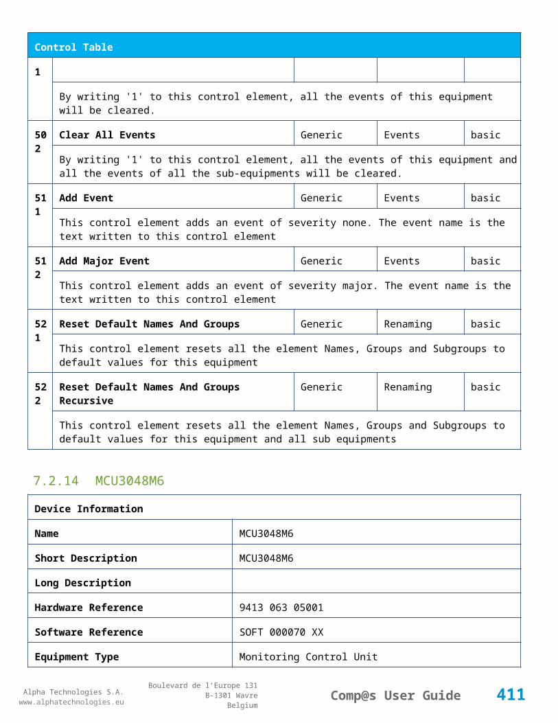
Alpha Technologies S.A.www.alphatechnologies.eu
Alpha Technologies S.A.www.alphatechnologies.eu
Comp@s User GuideBoulevard de l’Europe 131
B-1301 WavreBelgium
Config Table
Another Boolean condition to activate the dry alarm relay 1. The way to define boolean condition is detailed in the PLC chapter.
112
Dry Alarm 2 Alternative Boolean Condition
Relays Relay 2 plc
Another Boolean condition to activate the dry alarm relay 2. The way to define boolean condition is detailed in the PLC chapter.
113
Dry Alarm 3 Alternative Boolean Condition
Relays Relay 3 plc
Another Boolean condition to activate the dry alarm relay 3. The way to define boolean condition is detailed in the PLC chapter.
114
Dry Alarm 4 Alternative Boolean Condition
Relays Relay 4 plc
Another Boolean condition to activate the dry alarm relay 4. The way to define boolean condition is detailed in the PLC chapter.
131
Ambient Temperature Low
Sensors Temperature degree C basic
The temperature under which the alarm 'Ambiant Temperature Too Low' must be set.
132
Ambient Temperature High
Sensors Temperature degree C basic
The temperature under which the alarm 'Ambiant Temperature Too Low' must be set.
133
Ambient Temperature Hysteresis
Sensors Temperature degree C basic
The hysteresis on the 'Battery Temperature Too High' and 'Battery Temperature Too Low' alarms.
521
Read Access User Numbers
Generic Allowed Users (1,2,3,4,5) basic
The list of the user numbers which have read access to this equipment. The user numbers are coma separated. The accepted user id are 1,2,3,4 and 5. Ex: 1,3,4
522
Write Access User Numbers
Generic Allowed Users () basic
The list of the user numbers which have write access to this equipment. This means that these users can modify the configuration element, the alarm settings and use the control elements. The user numbers are coma separated. The accepted user ids are 1,2,3,4 and 5. Ex: 1,3,4
601
Event Table Length Generic Events 10/4000 (100) basic
The maximum length of the table. The value must be comprised between 10 and 4000
60 Event Table Length By Generic Events 10/4000 (100) basic
411

Alpha Technologies S.A.www.alphatechnologies.eu
Alpha Technologies S.A.www.alphatechnologies.eu
Comp@s User GuideBoulevard de l’Europe 131
B-1301 WavreBelgium
Config Table
2 Rectifier
The maximum length of the table. The value must be comprised between 10 and 4000
901
Number Of PLC Data PLC (0) plc
The number of PLC data. Every equipment can manage up to 20 user programmable data. Data elements are automatically added in the data table. Configuration parameters are added to set the PLC Data Name and the PLC Data Mathematical calculation. In order to use these functionalities, you need a license with the 'PLC' module
902
Number Of PLC Alarm PLC (0) plc
The number of PLC alarm. Every equipment can manage up to 20 user programmable alarms. Alarm elements are automatically added in the alarm table. The alarm parameters are added to set the PLC Alarm Name and the PLC Alarm Boolean condition. In order to use these functionalities, you need a licence with the 'PLC' module
Control Table
Id Name Group SubGroup License
1 Back To Float System basic
The dc system must go back in floating mode.
2 Start Battery Test System battery
The dc system must start a battery test.
3 Force Battery Test System battery
The dc system must force a battery test.
4 Start Boost Mode System battery
The dc system must go in boost mode.
11 Open The LVD LVD basic
Try to open the LVD. It could not work if the LVD is electronic, and the request will be canceled after 15 sec.
12 Close The LVD LVD basic
The LVD must be closed
21 Correct Battery Current Offset Battery basic
31 Reset Battery Current Integration Battery basic
412
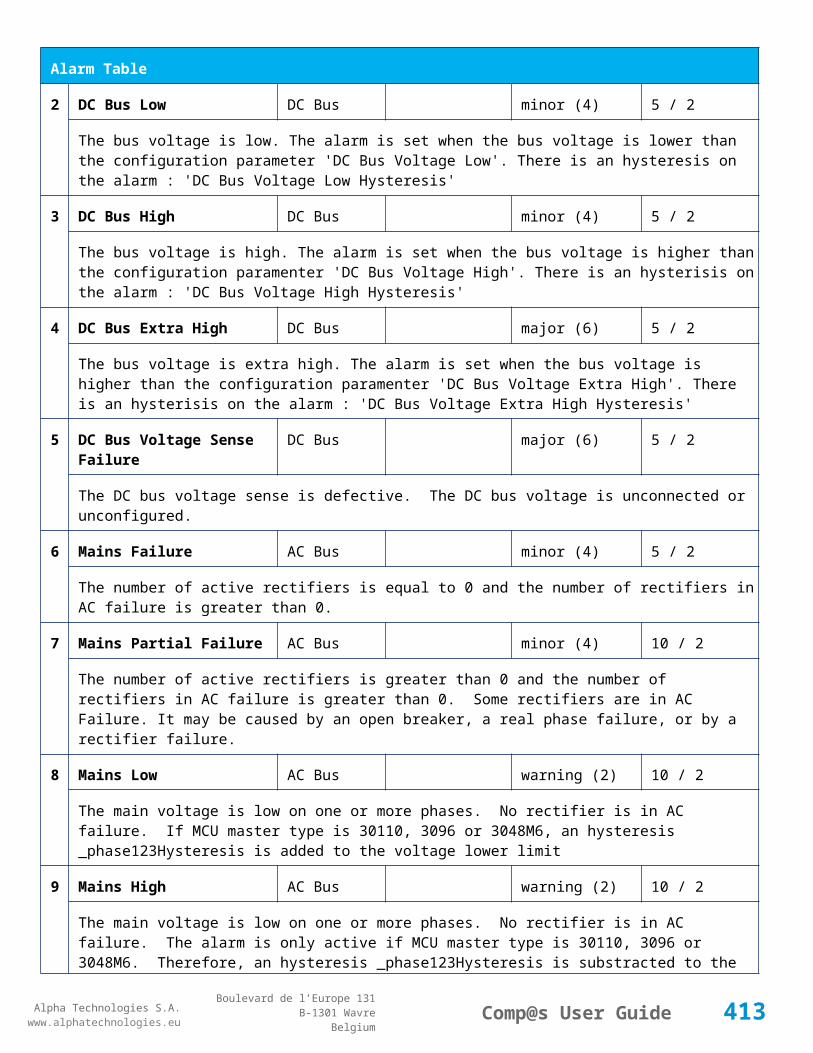
Alpha Technologies S.A.www.alphatechnologies.eu
Alpha Technologies S.A.www.alphatechnologies.eu
Comp@s User GuideBoulevard de l’Europe 131
B-1301 WavreBelgium
Control Table
Reset the integration of the battery current.
41 Reset Last Battery Test State Battery battery
Reset the state of the last battery test. If an alarm 'Battery Last Test Failed' is set, the alarm will be cleared.
51 Save Configuration In MCU Save basic
Save configuration parameters in the MCU microcontroller. If comp@s is not present, the system will be correctly managed.
55 Set MCU Specific Configuration Id Advanced Factory basic
This control allows to reconfigure the MCU to support specific hardware configuration, with embedded distribution for example
61 Set Digital Input 4 Counter Value Digital Inputs Digital Input 4 basic
Set Counter Value
111
Invert Relay 1 State For X Seconds Relays Relay 1 basic
Generate Pulse on relay 1
112
Invert Relay 2 State For X Seconds Relays Relay 2 basic
Generate Pulse on relay 2
113
Invert Relay 3 State For X Seconds Relays Relay 3 basic
Generate Pulse on relay 3
114
Invert Relay 4 State For X Seconds Relays Relay 4 basic
Generate Pulse on relay 4
501
Clear My Events Generic Events basic
By writing '1' to this control element, all the events of this equipment will be cleared.
502
Clear All Events Generic Events basic
By writing '1' to this control element, all the events of this equipment and all the events of all the sub-equipments will be cleared.
511
Add Event Generic Events basic
This control element adds an event of severity none. The event name is the text written to this control element
512
Add Major Event Generic Events basic
This control element adds an event of severity major. The event name is the text written to this control
413
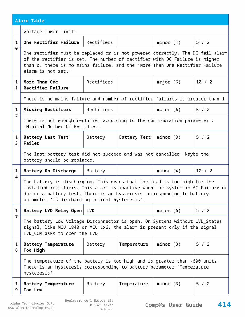
Alpha Technologies S.A.www.alphatechnologies.eu
Alpha Technologies S.A.www.alphatechnologies.eu
Comp@s User GuideBoulevard de l’Europe 131
B-1301 WavreBelgium
Control Table
element
521
Reset Default Names And Groups Generic Renaming basic
This control element resets all the element Names, Groups and Subgroups to default values for this equipment
522
Reset Default Names And Groups Recursive Generic Renaming basic
This control element resets all the element Names, Groups and Subgroups to default values for this equipment and all sub equipments
7.3 Rectifier Tables
7.3.1 CAR0548TN
Device Information
Name CAR0548TN
Short Description 500W switched mode rectifier
Long Description 500W switched mode rectifier, -48Vdc fixed output
Hardware Reference 9411 010 55001
Software Reference NO SOFT
Equipment Type Rectifier
ETSI Level /site/energy_system/dc_system/rectifier
Alarm Table
Id Name Group SubGroup Severity Type (Level) Set/Clear Delay
1 AC Failure major (0) 5 / 2
The rectifier is in AC Failure.
2 DC Failure major (0) 5 / 2
The rectifier must be replaced because of a DC Failure.
3 Over Temperature major (0) 5 / 2
The rectifier is too warm.
414
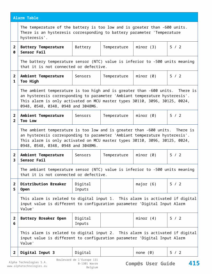
Alpha Technologies S.A.www.alphatechnologies.eu
Alpha Technologies S.A.www.alphatechnologies.eu
Comp@s User GuideBoulevard de l’Europe 131
B-1301 WavreBelgium
Alarm Table
4 Remote Off warning (0) 5 / 2
The rectifier is in remote off.
7 Communication Error warning (0) 5 / 2
The Communication With the rectifier has been lost.
Data Table
Id
Name Group SubGroup Unit License
1 Output Current Output Ampere basic
The current delivered by the rectifier
2 Output Power Output Watt basic
The power delivered by the rectifier
3 Output Voltage Output Volt basic
The output voltage of the rectifier
4 Output Current Max Output Ampere basic
The maximal current deliverable by the rectifier. This takes into account the derating for CAN capable rectifiers.
5 Output Power Max Output Watt basic
The maximal power deliverable by the rectifier. This takes into account the derating for CAN capable rectifiers.
7.3.2 CAR0948TN-1A / CAR0948TN-2A
Device Information
Name CAR0948TN-1A / CAR0948TN-2A
Short Description
850W switched mode rectifier / 850W switched mode rectifier
Long Description
850W switched mode rectifier, -48Vdc fixed output / 850W switched mode rectifier, -48Vdc fixed output. - non standard front plate
Hardware Reference
9411 010 95001 / 9411 010 95011
Software SOFT 000092 XX
415

Alpha Technologies S.A.www.alphatechnologies.eu
Alpha Technologies S.A.www.alphatechnologies.eu
Comp@s User GuideBoulevard de l’Europe 131
B-1301 WavreBelgium
Device Information
Reference
Equipment Type Rectifier
ETSI Level /site/energy_system/dc_system/rectifier
Description Table
Id Name Group SubGroup License
1 Product Name Product Info asset
The rectifier product name (With CAN capable rectifiers)
2 Hardware Reference Product Info asset
The rectifier hardware reference. This corresponds to the Mitra 12NC (With CAN capable rectifiers)
3 Hardware Revision Product Info asset
The rectifier hardware revision. (With CAN capable Rectifiers)
4 Software Reference Product Info asset
The rectifier software reference. This corresponds to the Mitra 12NC (With CAN capable rectifiers)
6 Serial Number Product Info asset
The rectifier serial number - Wb (With CAN capable rectifiers)
8 Manufacturing Date Product Info asset
The rectifier production date (With CAN capable rectifiers)
21 CAN Node Id CAN Bus basic
The CAN Bus Node ID
Alarm Table
Id Name Group SubGroup Severity Type (Level) Set/Clear Delay
1 AC Failure major (0) 5 / 2
The rectifier is in AC Failure.
2 DC Failure major (0) 5 / 2
The rectifier must be replaced because of a DC Failure.
416

Alpha Technologies S.A.www.alphatechnologies.eu
Alpha Technologies S.A.www.alphatechnologies.eu
Comp@s User GuideBoulevard de l’Europe 131
B-1301 WavreBelgium
Alarm Table
3 Over Temperature major (0) 5 / 2
The rectifier is too warm.
4 Remote Off warning (0) 5 / 2
The rectifier is in remote off.
7 Communication Error warning (0) 5 / 2
The Communication With the rectifier has been lost.
10 AC High minor (0) 5 / 2
The AC input in too high
11 Short Error major (0) 5 / 2
A short circuit is present on the bus
12 Fan Error major (0) 5 / 2
The FAN is defect
13 Derating Error major (0) 5 / 2
The rectifier is in derating
14 AC Derating major (0) 5 / 2
The rectifier is in AC derating
15 Thermal Derating major (0) 5 / 2
The rectifier is in thermal derating
Data Table
Id Name Group SubGroup Unit License
1 Output Current Output Ampere basic
The current delivered by the rectifier
2 Output Power Output Watt basic
The power delivered by the rectifier
3 Output Voltage Output Volt basic
The output voltage of the rectifier
417

Alpha Technologies S.A.www.alphatechnologies.eu
Alpha Technologies S.A.www.alphatechnologies.eu
Comp@s User GuideBoulevard de l’Europe 131
B-1301 WavreBelgium
Data Table
4 Output Current Max Output Ampere basic
The maximal current deliverable by the rectifier. This takes into account the derating for CAN capable rectifiers.
5 Output Power Max Output Watt basic
The maximal power deliverable by the rectifier. This takes into account the derating for CAN capable rectifiers.
11
Input Voltage Input Volt asset
The rectifier AC Input voltage (For CAN capable rectifiers)
12
Temperature General degree C asset
The rectifier temperature (For CAN capable rectifiers)
13
Fan Speed General RPM asset
The rectifier FAN Speed in RPM. (For CAN capable rectifiers)
14
Power Rating General % asset
The rectifier power rating (For CAN capable rectifiers)
15
Service Time General second asset
The rectifier total service time, in second (For CAN capable rectifiers)
16
Thermal Aging Time General second asset
The rectifier thermal aging time, in second (For CAN capable rectifiers)
17
Converted Energy General kJ asset
The total energy converted by the rectifier since the production. (For CAN capable rectifiers)
7.3.3 CAR0948TN-3A
Device Information
Name CAR0948TN-3A
Short Description 850W switched mode rectifier, AC & DC input
Long Description 850W switched mode rectifier, -48Vdc fixed output, AC and DC input
Hardware Reference 9411 010 95031
Software Reference SOFT 000084 XX
418

Alpha Technologies S.A.www.alphatechnologies.eu
Alpha Technologies S.A.www.alphatechnologies.eu
Comp@s User GuideBoulevard de l’Europe 131
B-1301 WavreBelgium
Device Information
Equipment Type Rectifier
ETSI Level /site/energy_system/dc_system/rectifier
Description Table
Id Name Group SubGroup License
1 Product Name Product Info asset
The rectifier product name (With CAN capable rectifiers)
2 Hardware Reference Product Info asset
The rectifier hardware reference. This corresponds to the Mitra 12NC (With CAN capable rectifiers)
3 Hardware Revision Product Info asset
The rectifier hardware revision. (With CAN capable Rectifiers)
4 Software Reference Product Info asset
The rectifier software reference. This corresponds to the Mitra 12NC (With CAN capable rectifiers)
6 Serial Number Product Info asset
The rectifier serial number - Wb (With CAN capable rectifiers)
8 Manufacturing Date Product Info asset
The rectifier production date (With CAN capable rectifiers)
21 CAN Node Id CAN Bus basic
The CAN Bus Node ID
Alarm Table
Id Name Group SubGroup Severity Type (Level) Set/Clear Delay
1 AC Failure major (0) 5 / 2
The rectifier is in AC Failure.
2 DC Failure major (0) 5 / 2
The rectifier must be replaced because of a DC Failure.
3 Over Temperature major (0) 5 / 2
419
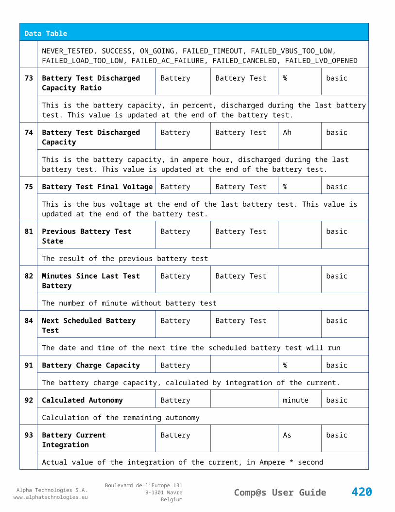
Alpha Technologies S.A.www.alphatechnologies.eu
Alpha Technologies S.A.www.alphatechnologies.eu
Comp@s User GuideBoulevard de l’Europe 131
B-1301 WavreBelgium
Alarm Table
The rectifier is too warm.
4 Remote Off warning (0) 5 / 2
The rectifier is in remote off.
7 Communication Error warning (0) 5 / 2
The Communication With the rectifier has been lost.
10 AC High minor (0) 5 / 2
The AC input in too high
11 Short Error major (0) 5 / 2
A short circuit is present on the bus
12 Fan Error major (0) 5 / 2
The FAN is defect
13 Derating Error major (0) 5 / 2
The rectifier is in derating
14 AC Derating major (0) 5 / 2
The rectifier is in AC derating
15 Thermal Derating major (0) 5 / 2
The rectifier is in thermal derating
Data Table
Id Name Group SubGroup Unit License
1 Output Current Output Ampere basic
The current delivered by the rectifier
2 Output Power Output Watt basic
The power delivered by the rectifier
3 Output Voltage Output Volt basic
The output voltage of the rectifier
4 Output Current Max Output Ampere basic
420

Alpha Technologies S.A.www.alphatechnologies.eu
Alpha Technologies S.A.www.alphatechnologies.eu
Comp@s User GuideBoulevard de l’Europe 131
B-1301 WavreBelgium
Data Table
The maximal current deliverable by the rectifier. This takes into account the derating for CAN capable rectifiers.
5 Output Power Max Output Watt basic
The maximal power deliverable by the rectifier. This takes into account the derating for CAN capable rectifiers.
11
Input Voltage Input Volt asset
The rectifier AC Input voltage (For CAN capable rectifiers)
12
Temperature General degree C asset
The rectifier temperature (For CAN capable rectifiers)
13
Fan Speed General RPM asset
The rectifier FAN Speed in RPM. (For CAN capable rectifiers)
14
Power Rating General % asset
The rectifier power rating (For CAN capable rectifiers)
15
Service Time General second asset
The rectifier total service time, in second (For CAN capable rectifiers)
16
Thermal Aging Time General second asset
The rectifier thermal aging time, in second (For CAN capable rectifiers)
17
Converted Energy General kJ asset
The total energy converted by the rectifier since the production. (For CAN capable rectifiers)
7.3.4 CAR1024TP
Device Information
Name CAR1024TP
Short Description 1000W switched mode rectifier
Long Description 1000W switched mode rectifier, +24Vdc fixed output
Hardware Reference 9411 011 02001
Software Reference NO SOFT
Equipment Type Rectifier
421

Alpha Technologies S.A.www.alphatechnologies.eu
Alpha Technologies S.A.www.alphatechnologies.eu
Comp@s User GuideBoulevard de l’Europe 131
B-1301 WavreBelgium
Device Information
ETSI Level /site/energy_system/dc_system/rectifier
Alarm Table
Id Name Group SubGroup Severity Type (Level) Set/Clear Delay
1 AC Failure major (0) 5 / 2
The rectifier is in AC Failure.
2 DC Failure major (0) 5 / 2
The rectifier must be replaced because of a DC Failure.
3 Over Temperature major (0) 5 / 2
The rectifier is too warm.
4 Remote Off warning (0) 5 / 2
The rectifier is in remote off.
7 Communication Error warning (0) 5 / 2
The Communication With the rectifier has been lost.
Data Table
Id
Name Group SubGroup Unit License
1 Output Current Output Ampere basic
The current delivered by the rectifier
2 Output Power Output Watt basic
The power delivered by the rectifier
3 Output Voltage Output Volt basic
The output voltage of the rectifier
4 Output Current Max Output Ampere basic
The maximal current deliverable by the rectifier. This takes into account the derating for CAN capable rectifiers.
5 Output Power Max Output Watt basic
The maximal power deliverable by the rectifier. This takes into account the derating for CAN capable
422

Alpha Technologies S.A.www.alphatechnologies.eu
Alpha Technologies S.A.www.alphatechnologies.eu
Comp@s User GuideBoulevard de l’Europe 131
B-1301 WavreBelgium
Data Table
rectifiers.
7.3.5 CAR1048TN-1A
Device Information
Name CAR1048TN-1A
Short Description 1000W switched mode rectifier
Long Description 1000W switched mode rectifier, -48Vdc fixed output
Hardware Reference 9411 011 05001
Software Reference SOFT 000067 XX
Equipment Type Rectifier
ETSI Level /site/energy_system/dc_system/rectifier
Description Table
Id Name Group SubGroup License
1 Product Name Product Info asset
The rectifier product name (With CAN capable rectifiers)
2 Hardware Reference Product Info asset
The rectifier hardware reference. This corresponds to the Mitra 12NC (With CAN capable rectifiers)
3 Hardware Revision Product Info asset
The rectifier hardware revision. (With CAN capable Rectifiers)
4 Software Reference Product Info asset
The rectifier software reference. This corresponds to the Mitra 12NC (With CAN capable rectifiers)
6 Serial Number Product Info asset
The rectifier serial number - Wb (With CAN capable rectifiers)
8 Manufacturing Date Product Info asset
The rectifier production date (With CAN capable rectifiers)
21 CAN Node Id CAN Bus basic
The CAN Bus Node ID
423

Alpha Technologies S.A.www.alphatechnologies.eu
Alpha Technologies S.A.www.alphatechnologies.eu
Comp@s User GuideBoulevard de l’Europe 131
B-1301 WavreBelgium
Description Table
Alarm Table
Id Name Group SubGroup Severity Type (Level) Set/Clear Delay
1 AC Failure major (0) 5 / 2
The rectifier is in AC Failure.
2 DC Failure major (0) 5 / 2
The rectifier must be replaced because of a DC Failure.
3 Over Temperature major (0) 5 / 2
The rectifier is too warm.
4 Remote Off warning (0) 5 / 2
The rectifier is in remote off.
7 Communication Error warning (0) 5 / 2
The Communication With the rectifier has been lost.
10 AC High minor (0) 5 / 2
The AC input in too high
11 Short Error major (0) 5 / 2
A short circuit is present on the bus
12 Fan Error major (0) 5 / 2
The FAN is defect
13 Derating Error major (0) 5 / 2
The rectifier is in derating
14 AC Derating major (0) 5 / 2
The rectifier is in AC derating
15 Thermal Derating major (0) 5 / 2
The rectifier is in thermal derating
424

Alpha Technologies S.A.www.alphatechnologies.eu
Alpha Technologies S.A.www.alphatechnologies.eu
Comp@s User GuideBoulevard de l’Europe 131
B-1301 WavreBelgium
Data Table
Id Name Group SubGroup Unit License
1 Output Current Output Ampere basic
The current delivered by the rectifier
2 Output Power Output Watt basic
The power delivered by the rectifier
3 Output Voltage Output Volt basic
The output voltage of the rectifier
4 Output Current Max Output Ampere basic
The maximal current deliverable by the rectifier. This takes into account the derating for CAN capable rectifiers.
5 Output Power Max Output Watt basic
The maximal power deliverable by the rectifier. This takes into account the derating for CAN capable rectifiers.
11
Input Voltage Input Volt asset
The rectifier AC Input voltage (For CAN capable rectifiers)
12
Temperature General degree C asset
The rectifier temperature (For CAN capable rectifiers)
13
Fan Speed General RPM asset
The rectifier FAN Speed in RPM. (For CAN capable rectifiers)
14
Power Rating General % asset
The rectifier power rating (For CAN capable rectifiers)
15
Service Time General second asset
The rectifier total service time, in second (For CAN capable rectifiers)
16
Thermal Aging Time General second asset
The rectifier thermal aging time, in second (For CAN capable rectifiers)
17
Converted Energy General kJ asset
The total energy converted by the rectifier since the production. (For CAN capable rectifiers)
425
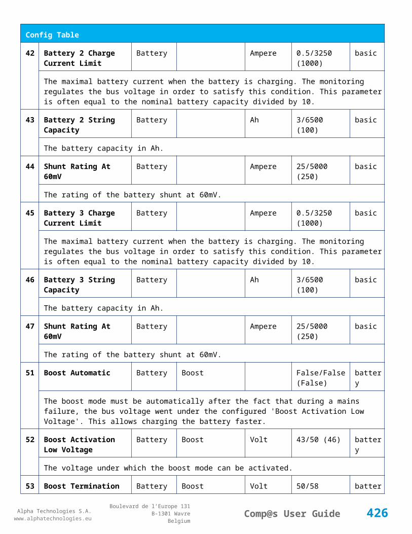
Alpha Technologies S.A.www.alphatechnologies.eu
Alpha Technologies S.A.www.alphatechnologies.eu
Comp@s User GuideBoulevard de l’Europe 131
B-1301 WavreBelgium
7.3.6 CAR1048TN-2A
Device Information
Name CAR1048TN-2A
Short Description 1000W switched mode rectifier, AC & DC input
Long Description 1000W switched mode rectifier, -48Vdc fixed output, AC & DC input
Hardware Reference 9411 011 05021
Software Reference SOFT 000083 XX
Equipment Type Rectifier
ETSI Level /site/energy_system/dc_system/rectifier
Description Table
Id Name Group SubGroup License
1 Product Name Product Info asset
The rectifier product name (With CAN capable rectifiers)
2 Hardware Reference Product Info asset
The rectifier hardware reference. This corresponds to the Mitra 12NC (With CAN capable rectifiers)
3 Hardware Revision Product Info asset
The rectifier hardware revision. (With CAN capable Rectifiers)
4 Software Reference Product Info asset
The rectifier software reference. This corresponds to the Mitra 12NC (With CAN capable rectifiers)
6 Serial Number Product Info asset
The rectifier serial number - Wb (With CAN capable rectifiers)
8 Manufacturing Date Product Info asset
The rectifier production date (With CAN capable rectifiers)
21 CAN Node Id CAN Bus basic
The CAN Bus Node ID
Alarm Table
Id Name Group SubGroup Severity Type (Level) Set/Clear Delay
426
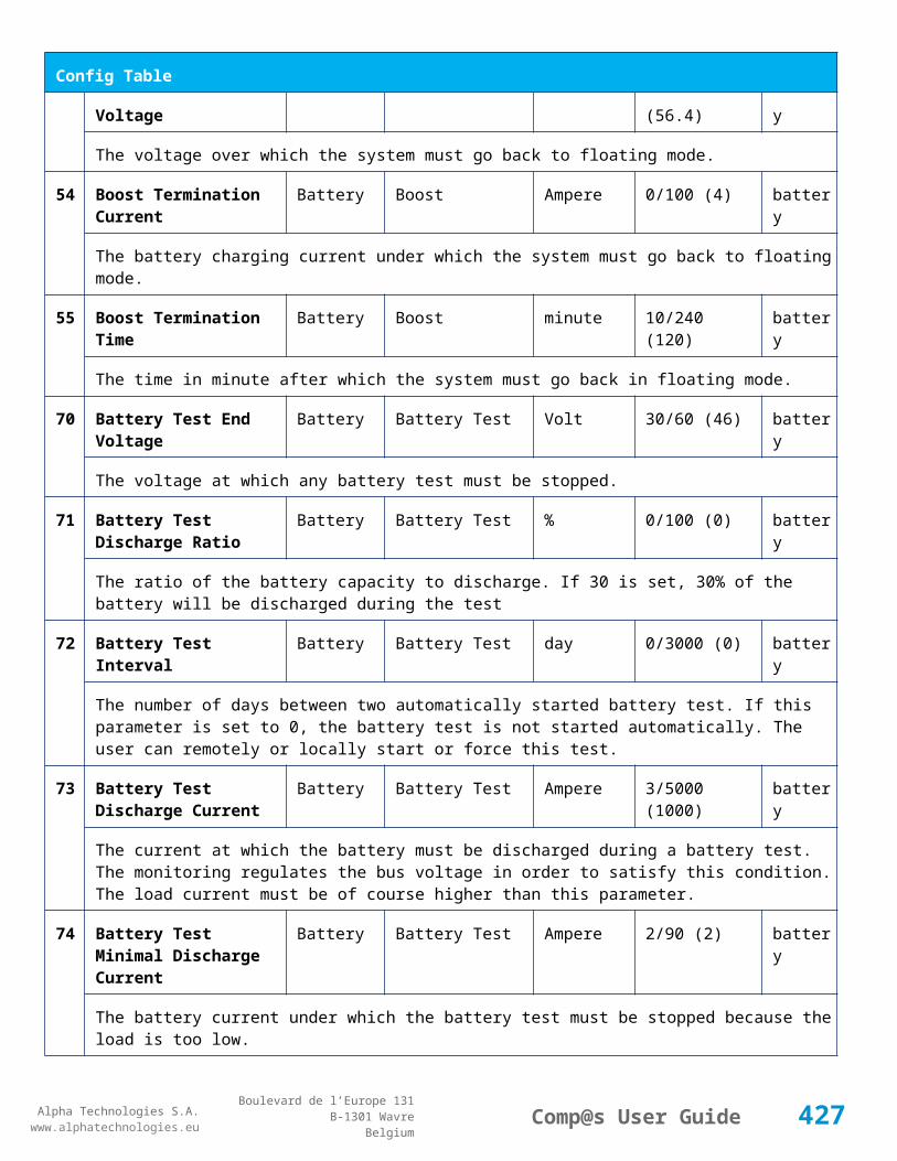
Alpha Technologies S.A.www.alphatechnologies.eu
Alpha Technologies S.A.www.alphatechnologies.eu
Comp@s User GuideBoulevard de l’Europe 131
B-1301 WavreBelgium
Alarm Table
1 AC Failure major (0) 5 / 2
The rectifier is in AC Failure.
2 DC Failure major (0) 5 / 2
The rectifier must be replaced because of a DC Failure.
3 Over Temperature major (0) 5 / 2
The rectifier is too warm.
4 Remote Off warning (0) 5 / 2
The rectifier is in remote off.
7 Communication Error warning (0) 5 / 2
The Communication With the rectifier has been lost.
10 AC High minor (0) 5 / 2
The AC input in too high
11 Short Error major (0) 5 / 2
A short circuit is present on the bus
12 Fan Error major (0) 5 / 2
The FAN is defect
13 Derating Error major (0) 5 / 2
The rectifier is in derating
14 AC Derating major (0) 5 / 2
The rectifier is in AC derating
15 Thermal Derating major (0) 5 / 2
The rectifier is in thermal derating
Data Table
Id Name Group SubGroup Unit License
1 Output Current Output Ampere basic
The current delivered by the rectifier
427

Alpha Technologies S.A.www.alphatechnologies.eu
Alpha Technologies S.A.www.alphatechnologies.eu
Comp@s User GuideBoulevard de l’Europe 131
B-1301 WavreBelgium
Data Table
2 Output Power Output Watt basic
The power delivered by the rectifier
3 Output Voltage Output Volt basic
The output voltage of the rectifier
4 Output Current Max Output Ampere basic
The maximal current deliverable by the rectifier. This takes into account the derating for CAN capable rectifiers.
5 Output Power Max Output Watt basic
The maximal power deliverable by the rectifier. This takes into account the derating for CAN capable rectifiers.
11
Input Voltage Input Volt asset
The rectifier AC Input voltage (For CAN capable rectifiers)
12
Temperature General degree C asset
The rectifier temperature (For CAN capable rectifiers)
13
Fan Speed General RPM asset
The rectifier FAN Speed in RPM. (For CAN capable rectifiers)
14
Power Rating General % asset
The rectifier power rating (For CAN capable rectifiers)
15
Service Time General second asset
The rectifier total service time, in second (For CAN capable rectifiers)
16
Thermal Aging Time General second asset
The rectifier thermal aging time, in second (For CAN capable rectifiers)
17
Converted Energy General kJ asset
The total energy converted by the rectifier since the production. (For CAN capable rectifiers)
7.3.7 CAR1548TN
Device Information
Name CAR1548TN
428

Alpha Technologies S.A.www.alphatechnologies.eu
Alpha Technologies S.A.www.alphatechnologies.eu
Comp@s User GuideBoulevard de l’Europe 131
B-1301 WavreBelgium
Device Information
Short Description 1500W switched mode rectifier
Long Description 1500W switched mode rectifier, -48Vdc fixed output
Hardware Reference 9411 011 55001
Software Reference NO SOFT
Equipment Type Rectifier
ETSI Level /site/energy_system/dc_system/rectifier
Alarm Table
Id Name Group SubGroup Severity Type (Level) Set/Clear Delay
1 AC Failure major (0) 5 / 2
The rectifier is in AC Failure.
2 DC Failure major (0) 5 / 2
The rectifier must be replaced because of a DC Failure.
3 Over Temperature major (0) 5 / 2
The rectifier is too warm.
4 Remote Off warning (0) 5 / 2
The rectifier is in remote off.
7 Communication Error warning (0) 5 / 2
The Communication With the rectifier has been lost.
Data Table
Id
Name Group SubGroup Unit License
1 Output Current Output Ampere basic
The current delivered by the rectifier
2 Output Power Output Watt basic
The power delivered by the rectifier
3 Output Voltage Output Volt basic
429
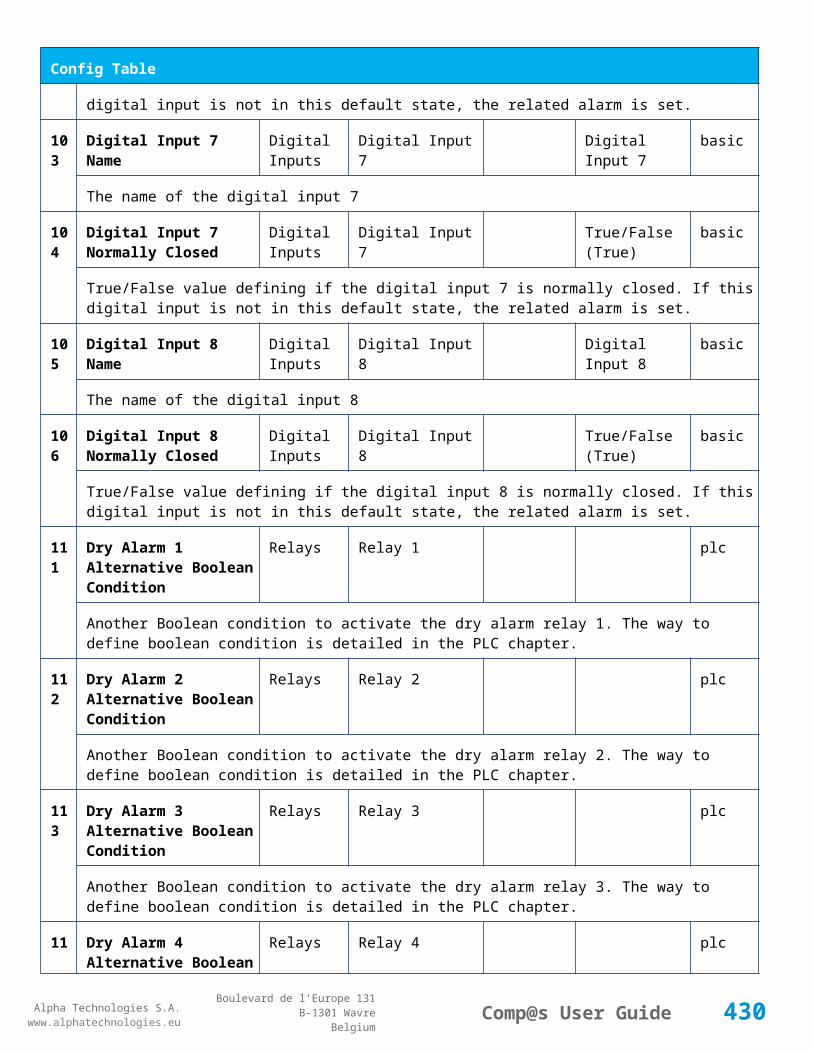
Alpha Technologies S.A.www.alphatechnologies.eu
Alpha Technologies S.A.www.alphatechnologies.eu
Comp@s User GuideBoulevard de l’Europe 131
B-1301 WavreBelgium
Data Table
The output voltage of the rectifier
4 Output Current Max Output Ampere basic
The maximal current deliverable by the rectifier. This takes into account the derating for CAN capable rectifiers.
5 Output Power Max Output Watt basic
The maximal power deliverable by the rectifier. This takes into account the derating for CAN capable rectifiers.
7.3.8 CAR1848TN-1A
Device Information
Name CAR1848TN-1A
Short Description 1800W switched mode rectifier
Long Description 1800W switched mode rectifier, -48Vdc fixed output
Hardware Reference 9411 011 85001
Software Reference NO SOFT
Equipment Type Rectifier
ETSI Level /site/energy_system/dc_system/rectifier
Alarm Table
Id Name Group SubGroup Severity Type (Level) Set/Clear Delay
1 AC Failure major (0) 5 / 2
The rectifier is in AC Failure.
2 DC Failure major (0) 5 / 2
The rectifier must be replaced because of a DC Failure.
3 Over Temperature major (0) 5 / 2
The rectifier is too warm.
4 Remote Off warning (0) 5 / 2
The rectifier is in remote off.
430
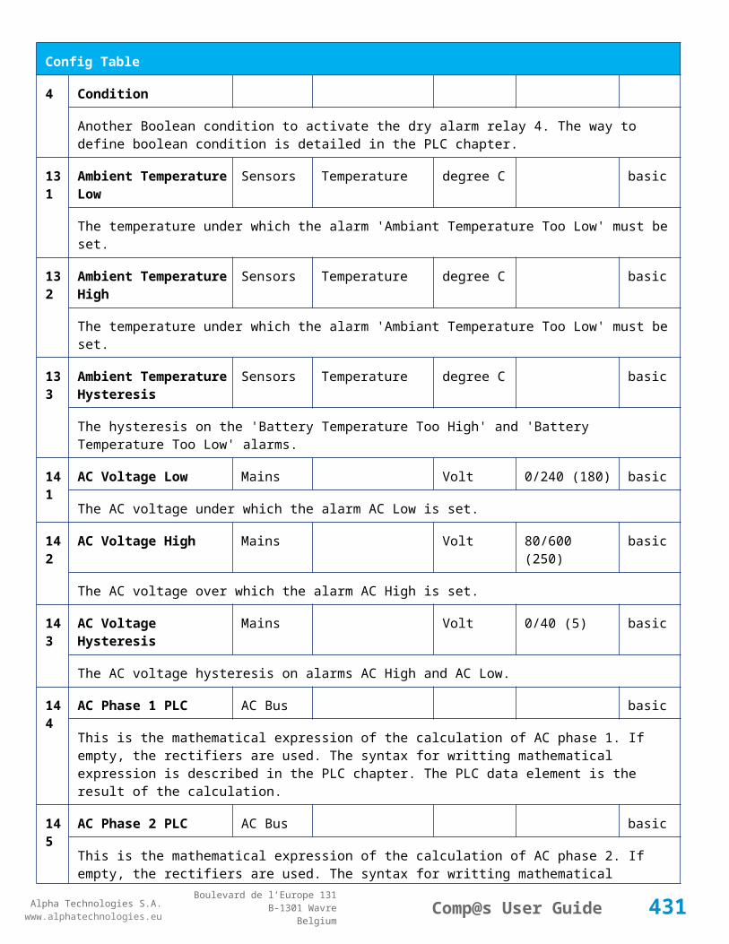
Alpha Technologies S.A.www.alphatechnologies.eu
Alpha Technologies S.A.www.alphatechnologies.eu
Comp@s User GuideBoulevard de l’Europe 131
B-1301 WavreBelgium
Alarm Table
7 Communication Error warning (0) 5 / 2
The Communication With the rectifier has been lost.
Data Table
Id
Name Group SubGroup Unit License
1 Output Current Output Ampere basic
The current delivered by the rectifier
2 Output Power Output Watt basic
The power delivered by the rectifier
3 Output Voltage Output Volt basic
The output voltage of the rectifier
4 Output Current Max Output Ampere basic
The maximal current deliverable by the rectifier. This takes into account the derating for CAN capable rectifiers.
5 Output Power Max Output Watt basic
The maximal power deliverable by the rectifier. This takes into account the derating for CAN capable rectifiers.
7.3.9 CAR1848TN-2A
Device Information
Name CAR1848TN-2A
Short Description 1800W switched mode rectifier extended input range
Long Description 1800W switched mode rectifier, -48Vdc fixed output, 150-280Vac input
Hardware Reference 9411 011 85011
Software Reference NO SOFT
Equipment Type Rectifier
ETSI Level /site/energy_system/dc_system/rectifier
431
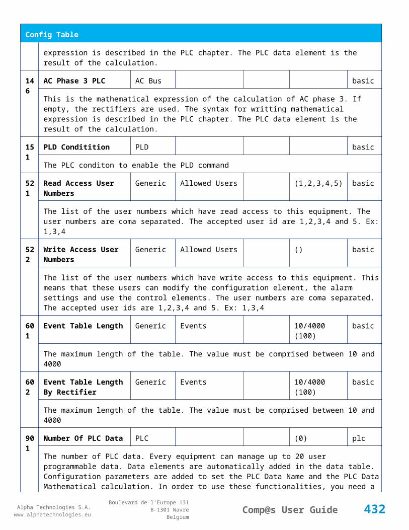
Alpha Technologies S.A.www.alphatechnologies.eu
Alpha Technologies S.A.www.alphatechnologies.eu
Comp@s User GuideBoulevard de l’Europe 131
B-1301 WavreBelgium
Alarm Table
Id Name Group SubGroup Severity Type (Level) Set/Clear Delay
1 AC Failure major (0) 5 / 2
The rectifier is in AC Failure.
2 DC Failure major (0) 5 / 2
The rectifier must be replaced because of a DC Failure.
3 Over Temperature major (0) 5 / 2
The rectifier is too warm.
4 Remote Off warning (0) 5 / 2
The rectifier is in remote off.
7 Communication Error warning (0) 5 / 2
The Communication With the rectifier has been lost.
Data Table
Id
Name Group SubGroup Unit License
1 Output Current Output Ampere basic
The current delivered by the rectifier
2 Output Power Output Watt basic
The power delivered by the rectifier
3 Output Voltage Output Volt basic
The output voltage of the rectifier
4 Output Current Max Output Ampere basic
The maximal current deliverable by the rectifier. This takes into account the derating for CAN capable rectifiers.
5 Output Power Max Output Watt basic
The maximal power deliverable by the rectifier. This takes into account the derating for CAN capable rectifiers.
432

Alpha Technologies S.A.www.alphatechnologies.eu
Alpha Technologies S.A.www.alphatechnologies.eu
Comp@s User GuideBoulevard de l’Europe 131
B-1301 WavreBelgium
7.3.10 CAR2648TN
Device Information
Name CAR2648TN
Short Description 1800W switched mode rectifier extended input range
Long Description 1800W switched mode rectifier, -48Vdc fixed output, 150-280Vac input
Hardware Reference 9411 012 65001
Software Reference SOFT 000075 XX
Equipment Type Rectifier
ETSI Level /site/energy_system/dc_system/rectifier
Alarm Table
Id Name Group SubGroup Severity Type (Level) Set/Clear Delay
1 AC Failure major (0) 5 / 2
The rectifier is in AC Failure.
2 DC Failure major (0) 5 / 2
The rectifier must be replaced because of a DC Failure.
3 Over Temperature major (0) 5 / 2
The rectifier is too warm.
4 Remote Off warning (0) 5 / 2
The rectifier is in remote off.
7 Communication Error warning (0) 5 / 2
The Communication With the rectifier has been lost.
Data Table
Id
Name Group SubGroup Unit License
1 Output Current Output Ampere basic
The current delivered by the rectifier
2 Output Power Output Watt basic
433

Alpha Technologies S.A.www.alphatechnologies.eu
Alpha Technologies S.A.www.alphatechnologies.eu
Comp@s User GuideBoulevard de l’Europe 131
B-1301 WavreBelgium
Data Table
The power delivered by the rectifier
3 Output Voltage Output Volt basic
The output voltage of the rectifier
4 Output Current Max Output Ampere basic
The maximal current deliverable by the rectifier. This takes into account the derating for CAN capable rectifiers.
5 Output Power Max Output Watt basic
The maximal power deliverable by the rectifier. This takes into account the derating for CAN capable rectifiers.
7.3.11 CAR30110TP
Device Information
Name CAR30110TP
Short Description 3000W +110V switched mode rectifier
Long Description 3000W switched mode rectifier, +110Vdc fixed output
Hardware Reference 9411 013 07001
Software Reference SOFT 000065 XX
Equipment Type Rectifier
ETSI Level /site/energy_system/dc_system/rectifier
Description Table
Id Name Group SubGroup License
1 Product Name Product Info asset
The rectifier product name (With CAN capable rectifiers)
2 Hardware Reference Product Info asset
The rectifier hardware reference. This corresponds to the Mitra 12NC (With CAN capable rectifiers)
3 Hardware Revision Product Info asset
The rectifier hardware revision. (With CAN capable Rectifiers)
434

Alpha Technologies S.A.www.alphatechnologies.eu
Alpha Technologies S.A.www.alphatechnologies.eu
Comp@s User GuideBoulevard de l’Europe 131
B-1301 WavreBelgium
Description Table
4 Software Reference Product Info asset
The rectifier software reference. This corresponds to the Mitra 12NC (With CAN capable rectifiers)
6 Serial Number Product Info asset
The rectifier serial number - Wb (With CAN capable rectifiers)
8 Manufacturing Date Product Info asset
The rectifier production date (With CAN capable rectifiers)
21 CAN Node Id CAN Bus basic
The CAN Bus Node ID
Alarm Table
Id Name Group SubGroup Severity Type (Level) Set/Clear Delay
1 AC Failure major (0) 5 / 2
The rectifier is in AC Failure.
2 DC Failure major (0) 5 / 2
The rectifier must be replaced because of a DC Failure.
3 Over Temperature major (0) 5 / 2
The rectifier is too warm.
4 Remote Off warning (0) 5 / 2
The rectifier is in remote off.
7 Communication Error warning (0) 5 / 2
The Communication With the rectifier has been lost.
10 AC High minor (0) 5 / 2
The AC input in too high
11 Short Error major (0) 5 / 2
A short circuit is present on the bus
12 Fan Error major (0) 5 / 2
The FAN is defect
435
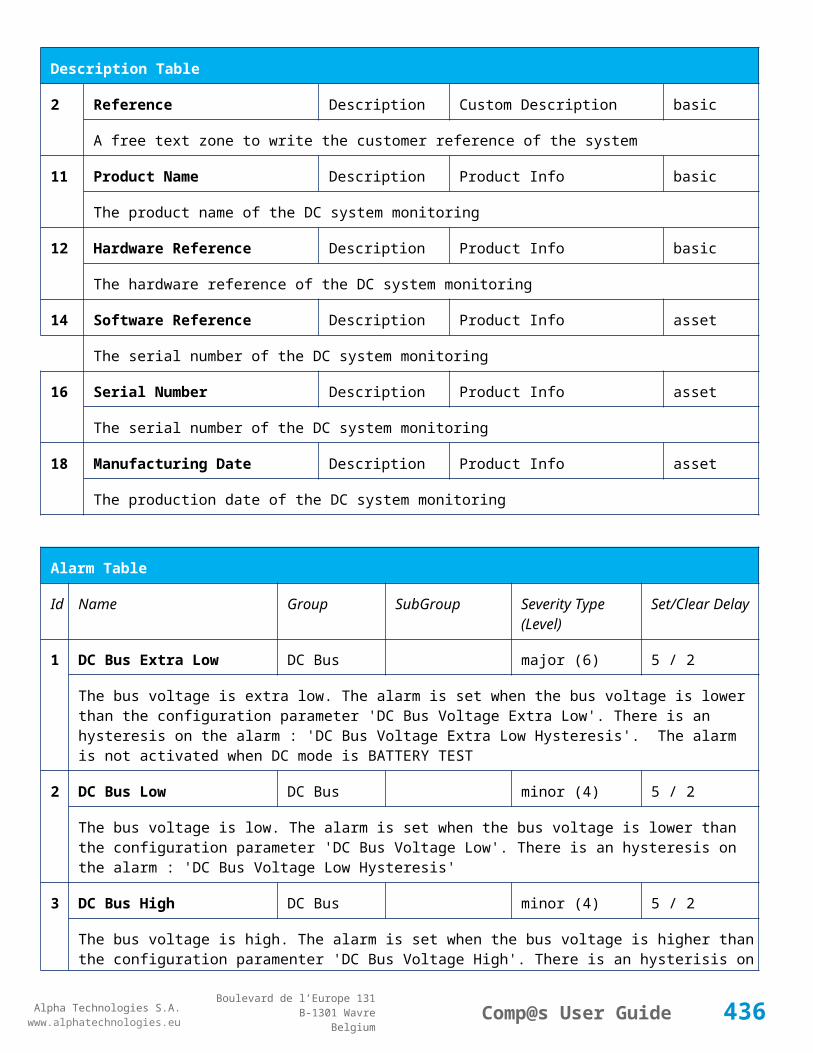
Alpha Technologies S.A.www.alphatechnologies.eu
Alpha Technologies S.A.www.alphatechnologies.eu
Comp@s User GuideBoulevard de l’Europe 131
B-1301 WavreBelgium
Alarm Table
13 Derating Error major (0) 5 / 2
The rectifier is in derating
14 AC Derating major (0) 5 / 2
The rectifier is in AC derating
15 Thermal Derating major (0) 5 / 2
The rectifier is in thermal derating
Data Table
Id Name Group SubGroup Unit License
1 Output Current Output Ampere basic
The current delivered by the rectifier
2 Output Power Output Watt basic
The power delivered by the rectifier
3 Output Voltage Output Volt basic
The output voltage of the rectifier
4 Output Current Max Output Ampere basic
The maximal current deliverable by the rectifier. This takes into account the derating for CAN capable rectifiers.
5 Output Power Max Output Watt basic
The maximal power deliverable by the rectifier. This takes into account the derating for CAN capable rectifiers.
11
Input Voltage Input Volt asset
The rectifier AC Input voltage (For CAN capable rectifiers)
12
Temperature General degree C asset
The rectifier temperature (For CAN capable rectifiers)
13
Fan Speed General RPM asset
The rectifier FAN Speed in RPM. (For CAN capable rectifiers)
1 Power Rating General % asset
436
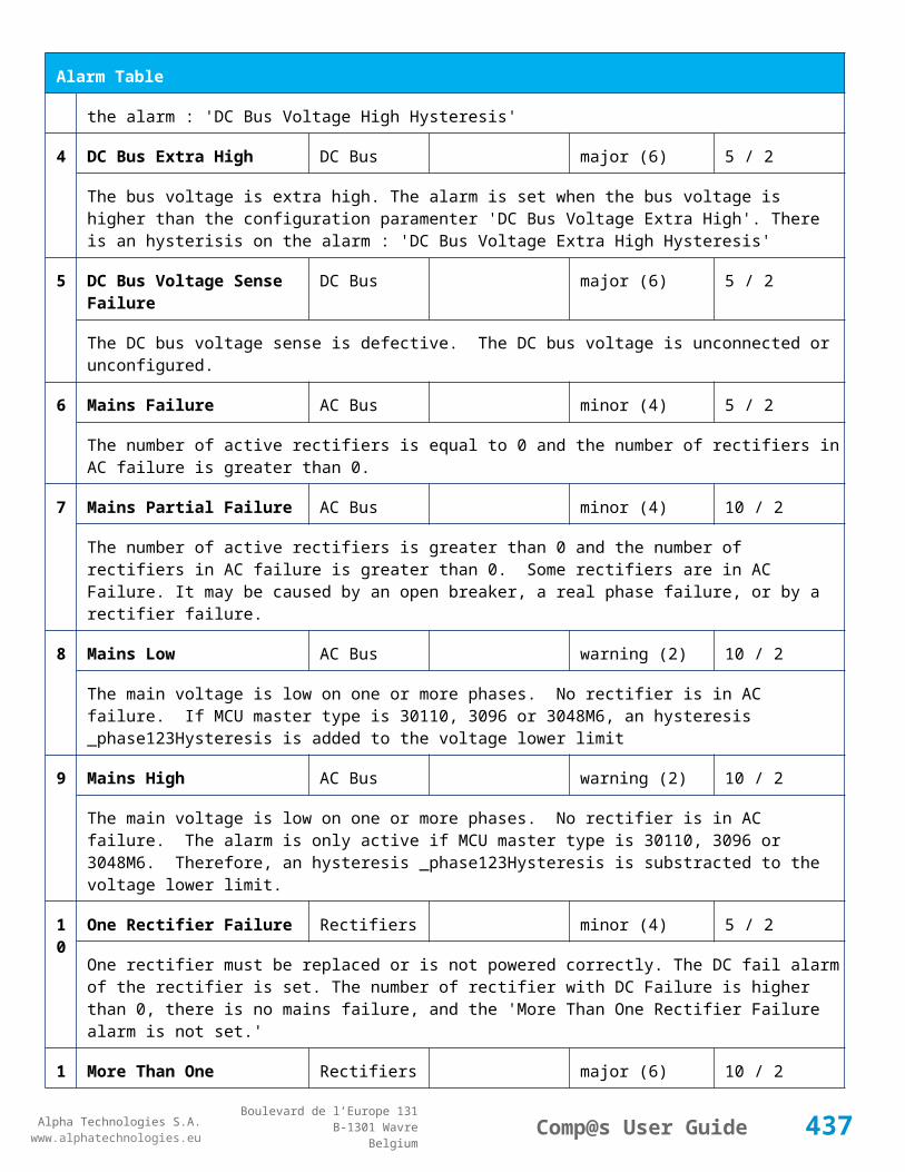
Alpha Technologies S.A.www.alphatechnologies.eu
Alpha Technologies S.A.www.alphatechnologies.eu
Comp@s User GuideBoulevard de l’Europe 131
B-1301 WavreBelgium
Data Table
4 The rectifier power rating (For CAN capable rectifiers)
15
Service Time General second asset
The rectifier total service time, in second (For CAN capable rectifiers)
16
Thermal Aging Time General second asset
The rectifier thermal aging time, in second (For CAN capable rectifiers)
17
Converted Energy General kJ asset
The total energy converted by the rectifier since the production. (For CAN capable rectifiers)
7.3.12 CAR30125TP
Device Information
Name CAR30125TP
Short Description 3000W +125V switched mode rectifier
Long Description 3000W switched mode rectifier, +125Vdc fixed output
Hardware Reference 9411 013 07011
Software Reference SOFT 000068 XX
Equipment Type Rectifier
ETSI Level /site/energy_system/dc_system/rectifier
Description Table
Id Name Group SubGroup License
1 Product Name Product Info asset
The rectifier product name (With CAN capable rectifiers)
2 Hardware Reference Product Info asset
The rectifier hardware reference. This corresponds to the Mitra 12NC (With CAN capable rectifiers)
3 Hardware Revision Product Info asset
The rectifier hardware revision. (With CAN capable Rectifiers)
4 Software Reference Product Info asset
The rectifier software reference. This corresponds to the Mitra 12NC (With CAN capable rectifiers)
437

Alpha Technologies S.A.www.alphatechnologies.eu
Alpha Technologies S.A.www.alphatechnologies.eu
Comp@s User GuideBoulevard de l’Europe 131
B-1301 WavreBelgium
Description Table
6 Serial Number Product Info asset
The rectifier serial number - Wb (With CAN capable rectifiers)
8 Manufacturing Date Product Info asset
The rectifier production date (With CAN capable rectifiers)
21 CAN Node Id CAN Bus basic
The CAN Bus Node ID
Alarm Table
Id Name Group SubGroup Severity Type (Level) Set/Clear Delay
1 AC Failure major (0) 5 / 2
The rectifier is in AC Failure.
2 DC Failure major (0) 5 / 2
The rectifier must be replaced because of a DC Failure.
3 Over Temperature major (0) 5 / 2
The rectifier is too warm.
4 Remote Off warning (0) 5 / 2
The rectifier is in remote off.
7 Communication Error warning (0) 5 / 2
The Communication With the rectifier has been lost.
10 AC High minor (0) 5 / 2
The AC input in too high
11 Short Error major (0) 5 / 2
A short circuit is present on the bus
12 Fan Error major (0) 5 / 2
The FAN is defect
13 Derating Error major (0) 5 / 2
438
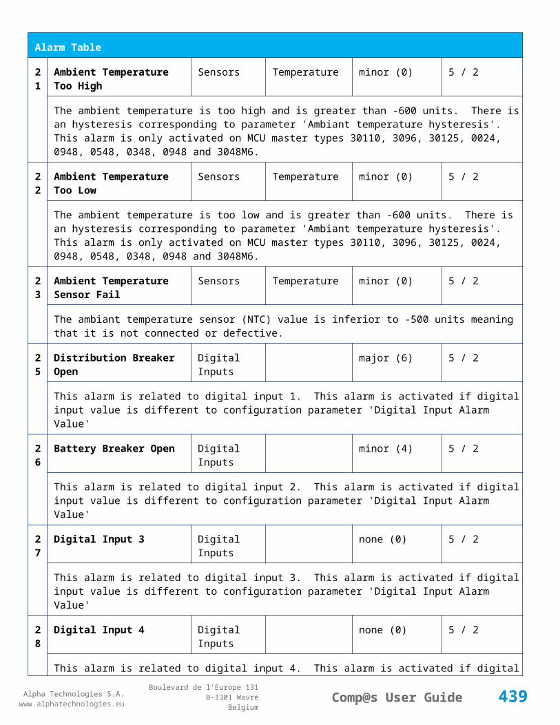
Alpha Technologies S.A.www.alphatechnologies.eu
Alpha Technologies S.A.www.alphatechnologies.eu
Comp@s User GuideBoulevard de l’Europe 131
B-1301 WavreBelgium
Alarm Table
The rectifier is in derating
14 AC Derating major (0) 5 / 2
The rectifier is in AC derating
15 Thermal Derating major (0) 5 / 2
The rectifier is in thermal derating
Data Table
Id Name Group SubGroup Unit License
1 Output Current Output Ampere basic
The current delivered by the rectifier
2 Output Power Output Watt basic
The power delivered by the rectifier
3 Output Voltage Output Volt basic
The output voltage of the rectifier
4 Output Current Max Output Ampere basic
The maximal current deliverable by the rectifier. This takes into account the derating for CAN capable rectifiers.
5 Output Power Max Output Watt basic
The maximal power deliverable by the rectifier. This takes into account the derating for CAN capable rectifiers.
11
Input Voltage Input Volt asset
The rectifier AC Input voltage (For CAN capable rectifiers)
12
Temperature General degree C asset
The rectifier temperature (For CAN capable rectifiers)
13
Fan Speed General RPM asset
The rectifier FAN Speed in RPM. (For CAN capable rectifiers)
14
Power Rating General % asset
The rectifier power rating (For CAN capable rectifiers)
439
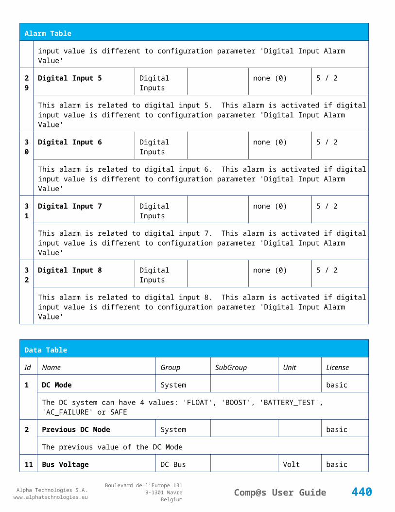
Alpha Technologies S.A.www.alphatechnologies.eu
Alpha Technologies S.A.www.alphatechnologies.eu
Comp@s User GuideBoulevard de l’Europe 131
B-1301 WavreBelgium
Data Table
15
Service Time General second asset
The rectifier total service time, in second (For CAN capable rectifiers)
16
Thermal Aging Time General second asset
The rectifier thermal aging time, in second (For CAN capable rectifiers)
17
Converted Energy General kJ asset
The total energy converted by the rectifier since the production. (For CAN capable rectifiers)
7.3.13 CDC1548TN
Device Information
Name CDC1548TN
Short Description 1500W DC/DC converter 110-220Vin/48Vout
Long Description 1500W DC/DC converter 110-220Vin/48Vout
Hardware Reference 9413 000 88001
Software Reference NO SOFT
Equipment Type Rectifier
ETSI Level /site/energy_system/dc_system/rectifier
Alarm Table
Id Name Group SubGroup Severity Type (Level) Set/Clear Delay
1 AC Failure major (0) 5 / 2
The rectifier is in AC Failure.
2 DC Failure major (0) 5 / 2
The rectifier must be replaced because of a DC Failure.
3 Over Temperature major (0) 5 / 2
The rectifier is too warm.
4 Remote Off warning (0) 5 / 2
The rectifier is in remote off.
440

Alpha Technologies S.A.www.alphatechnologies.eu
Alpha Technologies S.A.www.alphatechnologies.eu
Comp@s User GuideBoulevard de l’Europe 131
B-1301 WavreBelgium
Alarm Table
7 Communication Error warning (0) 5 / 2
The Communication With the rectifier has been lost.
Data Table
Id
Name Group SubGroup Unit License
1 Output Current Output Ampere basic
The current delivered by the rectifier
2 Output Power Output Watt basic
The power delivered by the rectifier
3 Output Voltage Output Volt basic
The output voltage of the rectifier
4 Output Current Max Output Ampere basic
The maximal current deliverable by the rectifier. This takes into account the derating for CAN capable rectifiers.
5 Output Power Max Output Watt basic
The maximal power deliverable by the rectifier. This takes into account the derating for CAN capable rectifiers.
7.3.14 Cordex 2.4KW
Device Information
Name Cordex 2.4KW
Short Description
Long Description Rectifier Cordex 48V 2.4kW
Hardware Reference Cordex 2.4KW
Software Reference
Equipment Type Rectifier
ETSI Level /site/energy_system/dc_system/rectifier
441
Alpha Technologies S.A.www.alphatechnologies.eu
Alpha Technologies S.A.www.alphatechnologies.eu
Comp@s User GuideBoulevard de l’Europe 131
B-1301 WavreBelgium
Description Table
Id Name Group SubGroup License
1 Product Name Product Info asset
The rectifier product name
4 Software Reference Product Info asset
The rectifier software reference
5 Serial Number Product Info asset
The rectifier serial number
21 CAN Node Id CAN Bus basic
The CAN Bus Node ID
Alarm Table
Id Name Group SubGroup Severity Type (Level) Set/Clear Delay
1 Rectifier Fail major (0) 10 / 2
The rectifier has at least one fail alarm active and is unable to output any power. It may need to be replaced.
2 Rectifier Minor minor (0) 10 / 2
The rectifier has at least one minor alarm active and may be unable to output full power.
3 AC Failure major (0) 5 / 2
The rectifier is in AC Failure.
4 Over Temperature major (0) 5 / 2
The rectifier is too warm.
5 Remote Off warning (0) 10 / 2
The rectifier is in remote off.
7 Communication Error warning (0) 5 / 2
The Communication With the rectifier has been lost.
10
Fan Error major (0) 5 / 2
One or more fans has stopped working
1 Current Limit warning (0) 5 / 2
442
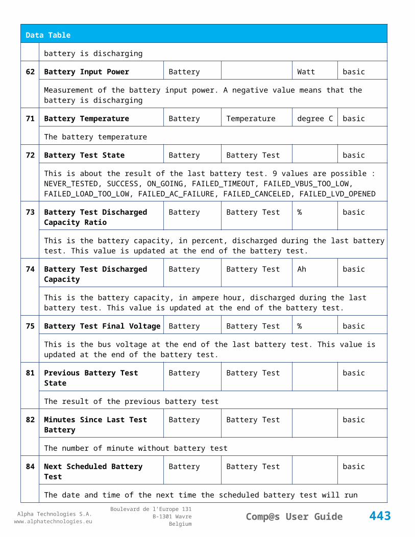
Alpha Technologies S.A.www.alphatechnologies.eu
Alpha Technologies S.A.www.alphatechnologies.eu
Comp@s User GuideBoulevard de l’Europe 131
B-1301 WavreBelgium
Alarm Table
1 The rectifier output current is at the maximum.
12
Power Limit warning (0) 5 / 2
The rectifier output power is at the maximum.
Data Table
Id Name Group SubGroup Unit License
1 Output Current Output Ampere basic
The current delivered by the rectifier
3 Output Voltage Output Volt basic
The output voltage of the rectifier
7 Power Ratio Output % basic
This is the ratio power/available power
8 Rectifier Mode Mode basic
The internal mode of the rectifier
11 Input Voltage Input Volt asset
The rectifier AC Input voltage (For CAN capable rectifiers)
12 Temperature General degree C asset
The rectifier temperature (For CAN capable rectifiers)
13 Phase Number General basic
The rectifier Phase - 0 means unconfigured
14 Service Time General minute asset
The rectifier total service time, in second (For CAN capable rectifiers)
15 Converted Energy General kWh asset
The total energy converted by the rectifier since the production. (For CAN capable rectifiers)
Control Table
Id Name Group SubGroup License
443

Alpha Technologies S.A.www.alphatechnologies.eu
Alpha Technologies S.A.www.alphatechnologies.eu
Comp@s User GuideBoulevard de l’Europe 131
B-1301 WavreBelgium
Control Table
1 Locate Rectifier Locate basic
5 Change Phase Number Phase basic
7.3.15 Cordex 4KW
Device Information
Name Cordex 4KW
Short Description
Long Description Rectifier Cordex 48V 4kW
Hardware Reference Cordex 4KW
Software Reference
Equipment Type Rectifier
ETSI Level /site/energy_system/dc_system/rectifier
Description Table
Id Name Group SubGroup License
1 Product Name Product Info asset
The rectifier product name
4 Software Reference Product Info asset
The rectifier software reference
5 Serial Number Product Info asset
The rectifier serial number
21 CAN Node Id CAN Bus basic
The CAN Bus Node ID
Alarm Table
Id Name Group SubGroup Severity Type (Level) Set/Clear Delay
444

Alpha Technologies S.A.www.alphatechnologies.eu
Alpha Technologies S.A.www.alphatechnologies.eu
Comp@s User GuideBoulevard de l’Europe 131
B-1301 WavreBelgium
Alarm Table
1 Rectifier Fail major (0) 10 / 2
The rectifier has at least one fail alarm active and is unable to output any power. It may need to be replaced.
2 Rectifier Minor minor (0) 10 / 2
The rectifier has at least one minor alarm active and may be unable to output full power.
3 AC Failure major (0) 5 / 2
The rectifier is in AC Failure.
4 Over Temperature major (0) 5 / 2
The rectifier is too warm.
5 Remote Off warning (0) 10 / 2
The rectifier is in remote off.
7 Communication Error warning (0) 5 / 2
The Communication With the rectifier has been lost.
10
Fan Error major (0) 5 / 2
One or more fans has stopped working
11
Current Limit warning (0) 5 / 2
The rectifier output current is at the maximum.
12
Power Limit warning (0) 5 / 2
The rectifier output power is at the maximum.
Data Table
Id Name Group SubGroup Unit License
1 Output Current Output Ampere basic
The current delivered by the rectifier
3 Output Voltage Output Volt basic
The output voltage of the rectifier
7 Power Ratio Output % basic
This is the ratio power/available power
445

Alpha Technologies S.A.www.alphatechnologies.eu
Alpha Technologies S.A.www.alphatechnologies.eu
Comp@s User GuideBoulevard de l’Europe 131
B-1301 WavreBelgium
Data Table
8 Rectifier Mode Mode basic
The internal mode of the rectifier
11 Input Voltage Input Volt asset
The rectifier AC Input voltage (For CAN capable rectifiers)
12 Temperature General degree C asset
The rectifier temperature (For CAN capable rectifiers)
13 Phase Number General basic
The rectifier Phase - 0 means unconfigured
14 Service Time General minute asset
The rectifier total service time, in second (For CAN capable rectifiers)
15 Converted Energy General kWh asset
The total energy converted by the rectifier since the production. (For CAN capable rectifiers)
Control Table
Id Name Group SubGroup License
1 Locate Rectifier Locate basic
5 Change Phase Number Phase basic
7.3.16 CXRF48-4kW
Device Information
Name CXRF48-4kW
Short Description 4kW high efficiency rectifier
Long Description Cordex HP 4kW, high efficiency switched mode rectifier, -48Vdc fixed output
Hardware Reference D010 623 20040
Software Reference Unknown
Equipment Type Rectifier
446

Alpha Technologies S.A.www.alphatechnologies.eu
Alpha Technologies S.A.www.alphatechnologies.eu
Comp@s User GuideBoulevard de l’Europe 131
B-1301 WavreBelgium
Device Information
ETSI Level /site/energy_system/dc_system/rectifier
Description Table
Id Name Group License
1 Product Name Product Info asset
The rectifier product name
4 Software Reference Product Info asset
The rectifier software reference
5 Serial Number Product Info asset
The rectifier serial number
21 CAN Node Id CAN Bus basic
The CAN Bus Node ID
Alarm Table
Id Name Severity Type (Level)
1 Rectifier Fail major (0)
The rectifier must be replaced because of a DC Failure.
2 Minor Problem minor (0)
There is a minor problem.
3 AC Failure major (0)
The rectifier is in AC Failure.
4 Over Temperature major (0)
The rectifier is too warm.
5 Remote Off warning (0)
The rectifier is in remote off.
7 Communication Error warning (0)
The Communication With the rectifier has been lost.
447

Alpha Technologies S.A.www.alphatechnologies.eu
Alpha Technologies S.A.www.alphatechnologies.eu
Comp@s User GuideBoulevard de l’Europe 131
B-1301 WavreBelgium
Alarm Table
10 Fan Error major (0)
The FAN is defect
11 Current Limitation warning (0)
The rectifier is in current limit
12 Power Limitation warning (0)
The rectifier is in power limit
Data Table
Id Name Group Unit License
1 Output Current Output Ampere basic
The current delivered by the rectifier
3 Output Voltage Output Volt basic
The output voltage of the rectifier
7 Power Ratio Output % basic
This is the ratio power/available power
8 Rectifier Mode Mode basic
The internal mode of the rectifier
11 Input Voltage Input Volt asset
The rectifier AC Input voltage (For CAN capable rectifiers)
12 Temperature General degree C asset
The rectifier temperature (For CAN capable rectifiers)
13 Phase Number General basic
The rectifier Phase - 0 means unconfigured
14 Service Time General second asset
The rectifier total service time, in second (For CAN capable rectifiers)
15 Converted Energy General kJ asset
448
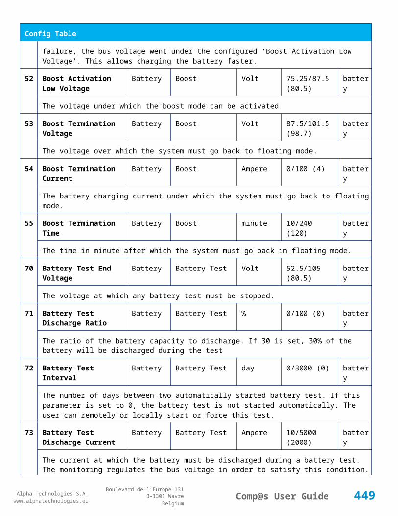
Alpha Technologies S.A.www.alphatechnologies.eu
Alpha Technologies S.A.www.alphatechnologies.eu
Comp@s User GuideBoulevard de l’Europe 131
B-1301 WavreBelgium
Data Table
The total energy converted by the rectifier since the production. (For CAN capable rectifiers)
Control Table
Id Name Group License
1 Locate Rectifier Locate basic
No information
5 Change Phase Number Phase basic
No information
7.3.17 CXRF 48-300W
Device Information
Name CXRF 48-300W
Short Description 300W high efficiency rectifier
Long Description Cordex HP 300W, high efficiency switched mode rectifier, -48Vdc fixed output
Hardware Reference 9411 010 35011
Software Reference SOFT 000101 XX
Equipment Type Rectifier
ETSI Level /site/energy_system/dc_system/rectifier
Description Table
Id Name Group SubGroup License
1 Product Name Product Info asset
The rectifier product name (With CAN capable rectifiers)
2 Hardware Reference Product Info asset
The rectifier hardware reference. This corresponds to the Mitra 12NC (With CAN capable rectifiers)
3 Hardware Revision Product Info asset
The rectifier hardware revision. (With CAN capable Rectifiers)
449
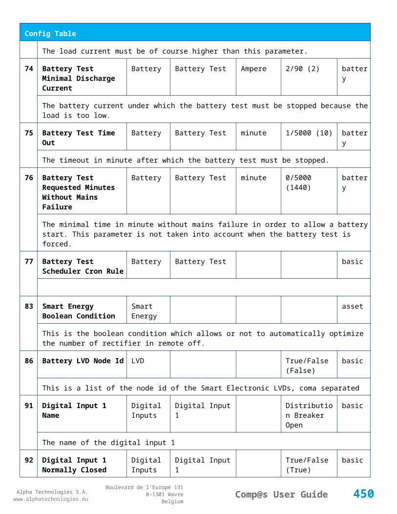
Alpha Technologies S.A.www.alphatechnologies.eu
Alpha Technologies S.A.www.alphatechnologies.eu
Comp@s User GuideBoulevard de l’Europe 131
B-1301 WavreBelgium
Description Table
4 Software Reference Product Info asset
The rectifier software reference. This corresponds to the Mitra 12NC (With CAN capable rectifiers)
6 Serial Number Product Info asset
The rectifier serial number - Wb (With CAN capable rectifiers)
8 Manufacturing Date Product Info asset
The rectifier production date (With CAN capable rectifiers)
21 CAN Node Id CAN Bus basic
The CAN Bus Node ID
Alarm Table
Id Name Group SubGroup Severity Type (Level) Set/Clear Delay
1 AC Failure major (0) 5 / 2
The rectifier is in AC Failure.
2 DC Failure major (0) 5 / 2
The rectifier must be replaced because of a DC Failure.
3 Over Temperature major (0) 5 / 2
The rectifier is too warm.
4 Remote Off warning (0) 5 / 2
The rectifier is in remote off.
7 Communication Error warning (0) 5 / 2
The Communication With the rectifier has been lost.
10 AC High minor (0) 5 / 2
The AC input in too high
11 Short Error major (0) 5 / 2
A short circuit is present on the bus
12 Fan Error major (0) 5 / 2
The FAN is defect
450

Alpha Technologies S.A.www.alphatechnologies.eu
Alpha Technologies S.A.www.alphatechnologies.eu
Comp@s User GuideBoulevard de l’Europe 131
B-1301 WavreBelgium
Alarm Table
13 Derating Error major (0) 5 / 2
The rectifier is in derating
14 AC Derating major (0) 5 / 2
The rectifier is in AC derating
15 Thermal Derating major (0) 5 / 2
The rectifier is in thermal derating
Data Table
Id Name Group SubGroup Unit License
1 Output Current Output Ampere basic
The current delivered by the rectifier
2 Output Power Output Watt basic
The power delivered by the rectifier
3 Output Voltage Output Volt basic
The output voltage of the rectifier
4 Output Current Max Output Ampere basic
The maximal current deliverable by the rectifier. This takes into account the derating for CAN capable rectifiers.
5 Output Power Max Output Watt basic
The maximal power deliverable by the rectifier. This takes into account the derating for CAN capable rectifiers.
11
Input Voltage Input Volt asset
The rectifier AC Input voltage (For CAN capable rectifiers)
12
Temperature General degree C asset
The rectifier temperature (For CAN capable rectifiers)
13
Fan Speed General RPM asset
The rectifier FAN Speed in RPM. (For CAN capable rectifiers)
1 Power Rating General % asset
451
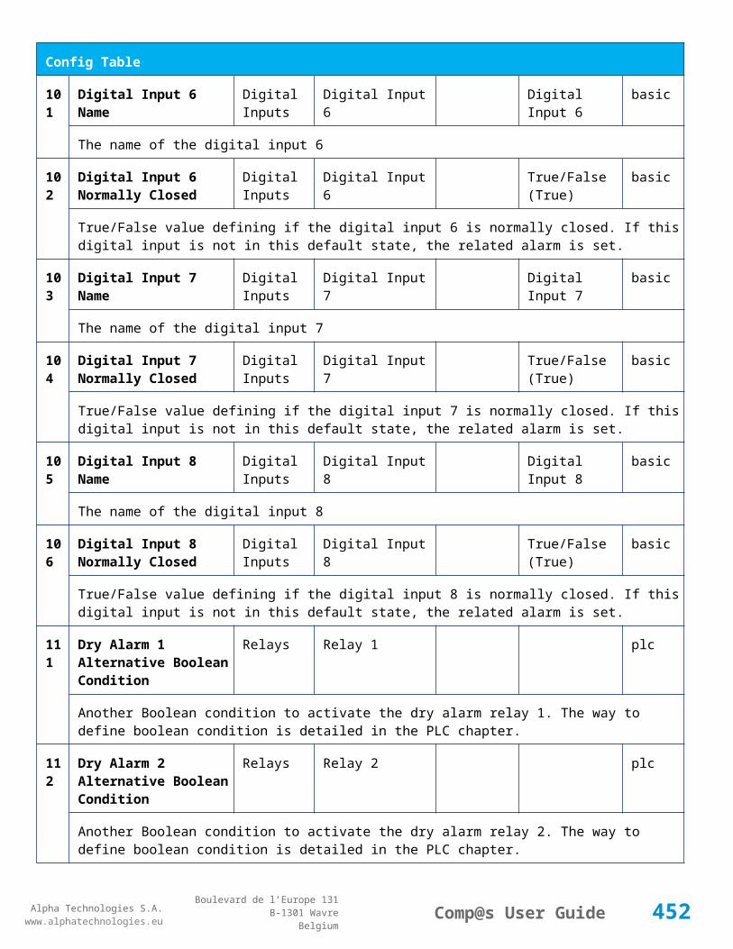
Alpha Technologies S.A.www.alphatechnologies.eu
Alpha Technologies S.A.www.alphatechnologies.eu
Comp@s User GuideBoulevard de l’Europe 131
B-1301 WavreBelgium
Data Table
4 The rectifier power rating (For CAN capable rectifiers)
15
Service Time General second asset
The rectifier total service time, in second (For CAN capable rectifiers)
16
Thermal Aging Time General second asset
The rectifier thermal aging time, in second (For CAN capable rectifiers)
17
Converted Energy General kJ asset
The total energy converted by the rectifier since the production. (For CAN capable rectifiers)
7.3.18 ECOR0348
Device Information
Name ECOR0348
Short Description Rectifer 300W -54V
Long Description Replaced by CXRF 48-300W
Hardware Reference 9411 010 35001
Software Reference SOFT 000097 XX
Equipment Type Rectifier
ETSI Level /site/energy_system/dc_system/rectifier
Description Table
Id Name Group SubGroup License
1 Product Name Product Info asset
The rectifier product name (With CAN capable rectifiers)
2 Hardware Reference Product Info asset
The rectifier hardware reference. This corresponds to the Mitra 12NC (With CAN capable rectifiers)
3 Hardware Revision Product Info asset
The rectifier hardware revision. (With CAN capable Rectifiers)
4 Software Reference Product Info asset
The rectifier software reference. This corresponds to the Mitra 12NC (With CAN capable rectifiers)
452
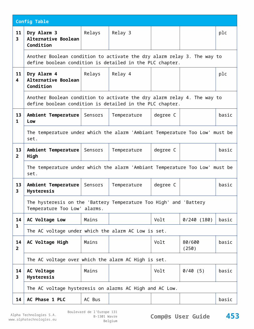
Alpha Technologies S.A.www.alphatechnologies.eu
Alpha Technologies S.A.www.alphatechnologies.eu
Comp@s User GuideBoulevard de l’Europe 131
B-1301 WavreBelgium
Description Table
6 Serial Number Product Info asset
The rectifier serial number - Wb (With CAN capable rectifiers)
8 Manufacturing Date Product Info asset
The rectifier production date (With CAN capable rectifiers)
21 CAN Node Id CAN Bus basic
The CAN Bus Node ID
Alarm Table
Id Name Group SubGroup Severity Type (Level) Set/Clear Delay
1 AC Failure major (0) 5 / 2
The rectifier is in AC Failure.
2 DC Failure major (0) 5 / 2
The rectifier must be replaced because of a DC Failure.
3 Over Temperature major (0) 5 / 2
The rectifier is too warm.
4 Remote Off warning (0) 5 / 2
The rectifier is in remote off.
7 Communication Error warning (0) 5 / 2
The Communication With the rectifier has been lost.
10 AC High minor (0) 5 / 2
The AC input in too high
11 Short Error major (0) 5 / 2
A short circuit is present on the bus
12 Fan Error major (0) 5 / 2
The FAN is defect
13 Derating Error major (0) 5 / 2
453

Alpha Technologies S.A.www.alphatechnologies.eu
Alpha Technologies S.A.www.alphatechnologies.eu
Comp@s User GuideBoulevard de l’Europe 131
B-1301 WavreBelgium
Alarm Table
The rectifier is in derating
14 AC Derating major (0) 5 / 2
The rectifier is in AC derating
15 Thermal Derating major (0) 5 / 2
The rectifier is in thermal derating
Data Table
Id Name Group SubGroup Unit License
1 Output Current Output Ampere basic
The current delivered by the rectifier
2 Output Power Output Watt basic
The power delivered by the rectifier
3 Output Voltage Output Volt basic
The output voltage of the rectifier
4 Output Current Max Output Ampere basic
The maximal current deliverable by the rectifier. This takes into account the derating for CAN capable rectifiers.
5 Output Power Max Output Watt basic
The maximal power deliverable by the rectifier. This takes into account the derating for CAN capable rectifiers.
11
Input Voltage Input Volt asset
The rectifier AC Input voltage (For CAN capable rectifiers)
12
Temperature General degree C asset
The rectifier temperature (For CAN capable rectifiers)
13
Fan Speed General RPM asset
The rectifier FAN Speed in RPM. (For CAN capable rectifiers)
14
Power Rating General % asset
The rectifier power rating (For CAN capable rectifiers)
454

Alpha Technologies S.A.www.alphatechnologies.eu
Alpha Technologies S.A.www.alphatechnologies.eu
Comp@s User GuideBoulevard de l’Europe 131
B-1301 WavreBelgium
Data Table
15
Service Time General second asset
The rectifier total service time, in second (For CAN capable rectifiers)
16
Thermal Aging Time General second asset
The rectifier thermal aging time, in second (For CAN capable rectifiers)
17
Converted Energy General kJ asset
The total energy converted by the rectifier since the production. (For CAN capable rectifiers)
7.4 Sensors And Actuators Tables
7.4.1 ADIO 7
Device Information
Name ADIO 7
Short Description Standard I/O module D24 T7
Long Description I/O module with 24 digital inputs and 7 inputs for temperature measurement
Hardware Reference 9413 060 05071
Software Reference SOFT 000095 XX
Equipment Type System Extension
ETSI Level /site/sensors_and_actuators
Description Table
Id Name Group SubGroup License
1 Product Name Description Product Info basic
The commercial name of the extension card.
2 Hardware Reference Description Product Info basic
The hardware refence
3 Hardware Revision Description Product Info basic
The hardware revision
455

Alpha Technologies S.A.www.alphatechnologies.eu
Alpha Technologies S.A.www.alphatechnologies.eu
Comp@s User GuideBoulevard de l’Europe 131
B-1301 WavreBelgium
Description Table
4 Software Reference Description Product Info basic
The software reference
6 Serial Number Description Product Info basic
The serial number.
8 Manufacturing Date Description Product Info basic
The production date.
11 Description Description Custom Description basic
A free text zone to write a system description
12 Reference Description Custom Description basic
A free text zone to write the customer reference of the system
Alarm Table
Id Name Group SubGroup Severity Type (Level) Set/Clear Delay
71 Digital Input 1 Digital Inputs Digital Input 1 warning (0) 5 / 2
The name of the digital input 1 alarm.
72 Digital Input 2 Digital Inputs Digital Input 2 warning (0) 5 / 2
The name of the digital input 2 alarm.
73 Digital Input 3 Digital Inputs Digital Input 3 warning (0) 5 / 2
The name of the digital input 3 alarm.
74 Digital Input 4 Digital Inputs Digital Input 4 warning (0) 5 / 2
The name of the digital input 4 alarm.
75 Digital Input 5 Digital Inputs Digital Input 5 warning (0) 5 / 2
The name of the digital input 5 alarm.
76 Digital Input 6 Digital Inputs Digital Input 6 warning (0) 5 / 2
The name of the digital input 6 alarm.
77 Digital Input 7 Digital Inputs Digital Input 7 warning (0) 5 / 2
The name of the digital input 7 alarm.
456

Alpha Technologies S.A.www.alphatechnologies.eu
Alpha Technologies S.A.www.alphatechnologies.eu
Comp@s User GuideBoulevard de l’Europe 131
B-1301 WavreBelgium
Alarm Table
78 Digital Input 8 Digital Inputs Digital Input 8 warning (0) 5 / 2
The name of the digital input 8 alarm.
79 Digital Input 9 Digital Inputs Digital Input 9 warning (0) 5 / 2
The name of the digital input 9 alarm.
80 Digital Input 10 Digital Inputs Digital Input 10 warning (0) 5 / 2
The name of the digital input 10 alarm.
81 Digital Input 11 Digital Inputs Digital Input 11 warning (0) 5 / 2
The name of the digital input 11 alarm.
82 Digital Input 12 Digital Inputs Digital Input 12 warning (0) 5 / 2
The name of the digital input 12 alarm.
83 Digital Input 13 Digital Inputs Digital Input 13 warning (0) 5 / 2
The name of the digital input 13 alarm.
84 Digital Input 14 Digital Inputs Digital Input 14 warning (0) 5 / 2
The name of the digital input 14 alarm.
85 Digital Input 15 Digital Inputs Digital Input 15 warning (0) 5 / 2
The name of the digital input 15 alarm.
86 Digital Input 16 Digital Inputs Digital Input 16 warning (0) 5 / 2
The name of the digital input 16 alarm.
87 Digital Input 17 Digital Inputs Digital Input 17 warning (0) 5 / 2
The name of the digital input 17 alarm.
88 Digital Input 18 Digital Inputs Digital Input 18 warning (0) 5 / 2
The name of the digital input 18 alarm.
89 Digital Input 19 Digital Inputs Digital Input 19 warning (0) 5 / 2
The name of the digital input 19 alarm.
90 Digital Input 20 Digital Inputs Digital Input 20 warning (0) 5 / 2
The name of the digital input 20 alarm.
91 Digital Input 21 Digital Inputs Digital Input 21 warning (0) 5 / 2
457

Alpha Technologies S.A.www.alphatechnologies.eu
Alpha Technologies S.A.www.alphatechnologies.eu
Comp@s User GuideBoulevard de l’Europe 131
B-1301 WavreBelgium
Alarm Table
The name of the digital input 21 alarm.
92 Digital Input 22 Digital Inputs Digital Input 22 warning (0) 5 / 2
The name of the digital input 22 alarm.
93 Digital Input 23 Digital Inputs Digital Input 23 warning (0) 5 / 2
The name of the digital input 23 alarm.
94 Digital Input 24 Digital Inputs Digital Input 24 warning (0) 5 / 2
The name of the digital input 24 alarm.
Data Table
Id Name Group SubGroup Unit License
1 Temperature 1 Temperature Sensors Temperature 1 degree C basic
Temperature Measurement 1
2 Temperature 2 Temperature Sensors Temperature 2 degree C basic
Temperature Measurement 2
3 Temperature 3 Temperature Sensors Temperature 3 degree C basic
Temperature Measurement 3
4 Temperature 4 Temperature Sensors Temperature 4 degree C basic
Temperature Measurement 4
5 Temperature 5 Temperature Sensors Temperature 5 degree C basic
Temperature Measurement 5
6 Temperature 6 Temperature Sensors Temperature 6 degree C basic
Temperature Measurement 6
7 Temperature 7 Temperature Sensors Temperature 7 degree C basic
Temperature Measurement 7
8 Temperature 8 Temperature Sensors Temperature 8 degree C basic
Temperature Measurement 8
71 Digital Input 1 State Digital Inputs Digital Input 1 basic
458

Alpha Technologies S.A.www.alphatechnologies.eu
Alpha Technologies S.A.www.alphatechnologies.eu
Comp@s User GuideBoulevard de l’Europe 131
B-1301 WavreBelgium
Data Table
The state of the digital input
72 Digital Input 2 State Digital Inputs Digital Input 2 basic
The state of the digital input
73 Digital Input 3 State Digital Inputs Digital Input 3 basic
The state of the digital input
74 Digital Input 4 State Digital Inputs Digital Input 4 basic
The state of the digital input
75 Digital Input 5 State Digital Inputs Digital Input 5 basic
The state of the digital input
76 Digital Input 6 State Digital Inputs Digital Input 6 basic
The state of the digital input
77 Digital Input 7 State Digital Inputs Digital Input 7 basic
The state of the digital input
78 Digital Input 8 State Digital Inputs Digital Input 8 basic
The state of the digital input
79 Digital Input 9 State Digital Inputs Digital Input 9 basic
The state of the digital input
80 Digital Input 10 State Digital Inputs Digital Input 10 basic
The state of the digital input
81 Digital Input 11 State Digital Inputs Digital Input 11 basic
The state of the digital input
82 Digital Input 12 State Digital Inputs Digital Input 12 basic
The state of the digital input
83 Digital Input 13 State Digital Inputs Digital Input 13 basic
The state of the digital input
84 Digital Input 14 State Digital Inputs Digital Input 14 basic
The state of the digital input
459

Alpha Technologies S.A.www.alphatechnologies.eu
Alpha Technologies S.A.www.alphatechnologies.eu
Comp@s User GuideBoulevard de l’Europe 131
B-1301 WavreBelgium
Data Table
85 Digital Input 15 State Digital Inputs Digital Input 15 basic
The state of the digital input
86 Digital Input 16 State Digital Inputs Digital Input 16 basic
The state of the digital input
87 Digital Input 17 State Digital Inputs Digital Input 17 basic
The state of the digital input
88 Digital Input 18 State Digital Inputs Digital Input 18 basic
The state of the digital input
89 Digital Input 19 State Digital Inputs Digital Input 19 basic
The state of the digital input
90 Digital Input 20 State Digital Inputs Digital Input 20 basic
The state of the digital input
91 Digital Input 21 State Digital Inputs Digital Input 21 basic
The state of the digital input
92 Digital Input 22 State Digital Inputs Digital Input 22 basic
The state of the digital input
93 Digital Input 23 State Digital Inputs Digital Input 23 basic
The state of the digital input
94 Digital Input 24 State Digital Inputs Digital Input 24 basic
The state of the digital input
131 Pulse Counter 1 Digital Inputs Digital Input 1 basic
Energy Consumption Counter 1
132 Pulse Counter 2 Digital Inputs Digital Input 2 basic
Energy Consumption Counter 2
133 Pulse Counter 3 Digital Inputs Digital Input 3 basic
Energy Consumption Counter 3
134 Pulse Counter 4 Digital Inputs Digital Input 4 basic
460
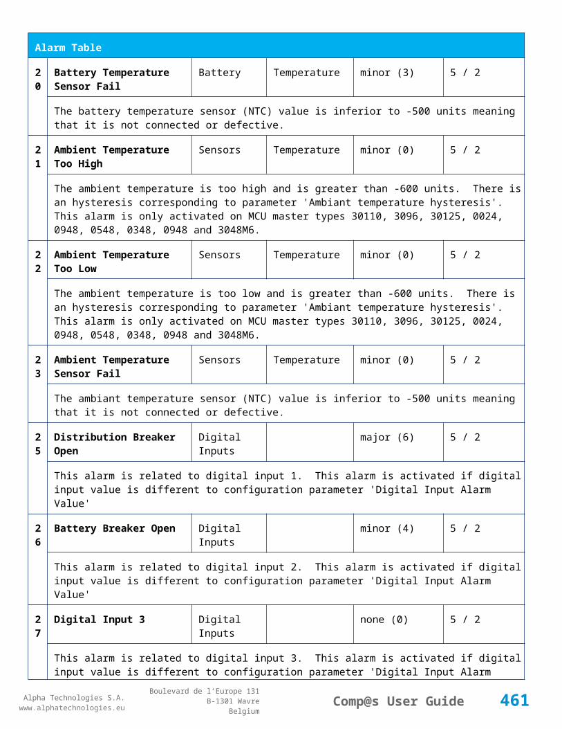
Alpha Technologies S.A.www.alphatechnologies.eu
Alpha Technologies S.A.www.alphatechnologies.eu
Comp@s User GuideBoulevard de l’Europe 131
B-1301 WavreBelgium
Data Table
Energy Consumption Counter 4
135 Pulse Counter 5 Digital Inputs Digital Input 5 basic
Energy Consumption Counter 5
136 Pulse Counter 6 Digital Inputs Digital Input 6 basic
Energy Consumption Counter 6
Config Table
Id Name Group SubGroup Unit Range: Min/Max (default)
License
71 Digital Input 1 Name Digital Inputs Digital Input 1 Digital Inputs basic
The name of the digital input 1.
72 Digital Input 1 Normally Closed
Digital Inputs Digital Input 1 True/False (True) basic
True/False value defining if the digital input 1 is normally closed. If this digital input is not in this default state, the related alarm is set.
73 Digital Input 2 Name Digital Inputs Digital Input 2 Digital Inputs basic
The name of the digital input 2.
74 Digital Input 2 Normally Closed
Digital Inputs Digital Input 2 True/False (True) basic
True/False value defining if the digital input 2 is normally closed. If this digital input is not in this default state, the related alarm is set.
75 Digital Input 3 Name Digital Inputs Digital Input 3 Digital Inputs basic
The name of the digital input 3.
76 Digital Input 3 Normally Closed
Digital Inputs Digital Input 3 True/False (True) basic
True/False value defining if the digital input 3 is normally closed. If this digital input is not in this default state, the related alarm is set.
77 Digital Input 4 Name Digital Inputs Digital Input 4 Digital Inputs basic
The name of the digital input 4.
78 Digital Input 4 Normally Closed
Digital Inputs Digital Input 4 True/False (True) basic
461

Alpha Technologies S.A.www.alphatechnologies.eu
Alpha Technologies S.A.www.alphatechnologies.eu
Comp@s User GuideBoulevard de l’Europe 131
B-1301 WavreBelgium
Config Table
True/False value defining if the digital input 4 is normally closed. If this digital input is not in this default state, the related alarm is set.
79 Digital Input 5 Name Digital Inputs Digital Input 5 Digital Inputs basic
The name of the digital input 5.
80 Digital Input 5 Normally Closed
Digital Inputs Digital Input 5 True/False (True) basic
True/False value defining if the digital input 5 is normally closed. If this digital input is not in this default state, the related alarm is set.
81 Digital Input 6 Name Digital Inputs Digital Input 6 Digital Inputs basic
The name of the digital input 6.
82 Digital Input 6 Normally Closed
Digital Inputs Digital Input 6 True/False (True) basic
True/False value defining if the digital input 6 is normally closed. If this digital input is not in this default state, the related alarm is set.
83 Digital Input 7 Name Digital Inputs Digital Input 7 Digital Inputs basic
The name of the digital input 7.
84 Digital Input 7 Normally Closed
Digital Inputs Digital Input 7 True/False (True) basic
True/False value defining if the digital input 7 is normally closed. If this digital input is not in this default state, the related alarm is set.
85 Digital Input 8 Name Digital Inputs Digital Input 8 Digital Inputs basic
The name of the digital input 8.
86 Digital Input 8 Normally Closed
Digital Inputs Digital Input 8 True/False (True) basic
True/False value defining if the digital input 8 is normally closed. If this digital input is not in this default state, the related alarm is set.
87 Digital Input 9 Name Digital Inputs Digital Input 9 Digital Inputs basic
The name of the digital input 9.
88 Digital Input 9 Normally Closed
Digital Inputs Digital Input 9 True/False (True) basic
True/False value defining if the digital input 9 is normally closed. If this digital input is not in this default state, the related alarm is set.
89 Digital Input 10 Name Digital Inputs Digital Input 10 Digital Inputs basic
462

Alpha Technologies S.A.www.alphatechnologies.eu
Alpha Technologies S.A.www.alphatechnologies.eu
Comp@s User GuideBoulevard de l’Europe 131
B-1301 WavreBelgium
Config Table
The name of the digital input 10.
90 Digital Input 10 Normally Closed
Digital Inputs Digital Input 10 True/False (True) basic
True/False value defining if the digital input 10 is normally closed. If this digital input is not in this default state, the related alarm is set.
91 Digital Input 11 Name Digital Inputs Digital Input 11 Digital Inputs basic
The name of the digital input 11.
92 Digital Input 11 Normally Closed
Digital Inputs Digital Input 11 True/False (True) basic
True/False value defining if the digital input 11 is normally closed. If this digital input is not in this default state, the related alarm is set.
93 Digital Input 12 Name Digital Inputs Digital Input 12 Digital Inputs basic
The name of the digital input 12.
94 Digital Input 12 Normally Closed
Digital Inputs Digital Input 12 True/False (True) basic
True/False value defining if the digital input 12 is normally closed. If this digital input is not in this default state, the related alarm is set.
95 Digital Input 13 Name Digital Inputs Digital Input 13 Digital Inputs basic
The name of the digital input 13.
96 Digital Input 13 Normally Closed
Digital Inputs Digital Input 13 True/False (True) basic
True/False value defining if the digital input 13 is normally closed. If this digital input is not in this default state, the related alarm is set.
97 Digital Input 14 Name Digital Inputs Digital Input 14 Digital Inputs basic
The name of the digital input 14.
98 Digital Input 14 Normally Closed
Digital Inputs Digital Input 14 True/False (True) basic
True/False value defining if the digital input 14 is normally closed. If this digital input is not in this default state, the related alarm is set.
99 Digital Input 15 Name Digital Inputs Digital Input 15 Digital Inputs basic
The name of the digital input 15.
100
Digital Input 15 Normally Closed
Digital Inputs Digital Input 15 True/False (True) basic
463

Alpha Technologies S.A.www.alphatechnologies.eu
Alpha Technologies S.A.www.alphatechnologies.eu
Comp@s User GuideBoulevard de l’Europe 131
B-1301 WavreBelgium
Config Table
True/False value defining if the digital input 15 is normally closed. If this digital input is not in this default state, the related alarm is set.
101
Digital Input 16 Name Digital Inputs Digital Input 16 Digital Inputs basic
The name of the digital input 16.
102
Digital Input 16 Normally Closed
Digital Inputs Digital Input 16 True/False (True) basic
True/False value defining if the digital input 16 is normally closed. If this digital input is not in this default state, the related alarm is set.
103
Digital Input 17 Name Digital Inputs Digital Input 17 Digital Inputs basic
The name of the digital input 17.
104
Digital Input 17 Normally Closed
Digital Inputs Digital Input 17 True/False (True) basic
True/False value defining if the digital input 17 is normally closed. If this digital input is not in this default state, the related alarm is set.
105
Digital Input 18 Name Digital Inputs Digital Input 18 Digital Inputs basic
The name of the digital input 18.
106
Digital Input 18 Normally Closed
Digital Inputs Digital Input 18 True/False (True) basic
True/False value defining if the digital input 18 is normally closed. If this digital input is not in this default state, the related alarm is set.
107
Digital Input 19 Name Digital Inputs Digital Input 19 Digital Inputs basic
The name of the digital input 19.
108
Digital Input 19 Normally Closed
Digital Inputs Digital Input 19 True/False (True) basic
True/False value defining if the digital input 19 is normally closed. If this digital input is not in this default state, the related alarm is set.
109
Digital Input 20 Name Digital Inputs Digital Input 20 Digital Inputs basic
The name of the digital input 20.
110
Digital Input 20 Normally Closed
Digital Inputs Digital Input 20 True/False (True) basic
True/False value defining if the digital input 20 is normally closed. If this digital input is not in this default state, the related alarm is set.
11 Digital Input 21 Name Digital Inputs Digital Input 21 Digital Inputs basic
464

Alpha Technologies S.A.www.alphatechnologies.eu
Alpha Technologies S.A.www.alphatechnologies.eu
Comp@s User GuideBoulevard de l’Europe 131
B-1301 WavreBelgium
Config Table
1 The name of the digital input 21.
112
Digital Input 21 Normally Closed
Digital Inputs Digital Input 21 True/False (True) basic
True/False value defining if the digital input 21 is normally closed. If this digital input is not in this default state, the related alarm is set.
113
Digital Input 22 Name Digital Inputs Digital Input 22 Digital Inputs basic
The name of the digital input 22.
114
Digital Input 22 Normally Closed
Digital Inputs Digital Input 22 True/False (True) basic
True/False value defining if the digital input 22 is normally closed. If this digital input is not in this default state, the related alarm is set.
115
Digital Input 23 Name Digital Inputs Digital Input 23 Digital Inputs basic
The name of the digital input 23.
116
Digital Input 23 Normally Closed
Digital Inputs Digital Input 23 True/False (True) basic
True/False value defining if the digital input 23 is normally closed. If this digital input is not in this default state, the related alarm is set.
117
Digital Input 24 Name Digital Inputs Digital Input 24 Digital Inputs basic
The name of the digital input 24.
118
Digital Input 24 Normally Closed
Digital Inputs Digital Input 24 True/False (True) basic
True/False value defining if the digital input 24 is normally closed. If this digital input is not in this default state, the related alarm is set.
521
Read Access User Numbers
Generic Allowed Users (1,2,3,4,5) basic
The list of the user numbers which have read access to this equipment. The user numbers are coma separated. The accepted user id are 1,2,3,4 and 5. Ex: 1,3,4
522
Write Access User Numbers
Generic Allowed Users () basic
The list of the user numbers which have write access to this equipment. This means that these users can modify the configuration element, the alarm settings and use the control elements. The user numbers are coma separated. The accepted user ids are 1,2,3,4 and 5. Ex: 1,3,4
601
Event Table Length Generic Events 10/4000 (100) basic
The maximum length of the table. The value must be comprised between 10 and 4000
465

Alpha Technologies S.A.www.alphatechnologies.eu
Alpha Technologies S.A.www.alphatechnologies.eu
Comp@s User GuideBoulevard de l’Europe 131
B-1301 WavreBelgium
Config Table
901
Number Of PLC Data PLC (0) plc
The number of PLC data. Every equipment can manage up to 20 user programmable data. Data elements are automatically added in the data table. Configuration parameters are added to set the PLC Data Name and the PLC Data Mathematical calculation. In order to use these functionalities, you need a license with the 'PLC' module
902
Number Of PLC Alarm PLC (0) plc
The number of PLC alarm. Every equipment can manage up to 20 user programmable alarms. Alarm elements are automatically added in the alarm table. The alarm parameters are added to set the PLC Alarm Name and the PLC Alarm Boolean condition. In order to use these functionalities, you need a licence with the 'PLC' module
Control Table
Id Name Group SubGroup License
101
Set Pulse Counter 1 Pulse Counter basic
Set Counter 1 Value
102
Set Pulse Counter 2 Pulse Counter basic
Set Counter 2 Value
103
Set Pulse Counter 3 Pulse Counter basic
Set Counter 3 Value
104
Set Pulse Counter 4 Pulse Counter basic
Set Counter 4 Value
105
Set Pulse Counter 5 Pulse Counter basic
Set Counter 5 Value
106
Set Pulse Counter 6 Pulse Counter basic
Set Counter 6 Value
501
Clear My Events Generic Events basic
By writing '1' to this control element, all the events of this equipment will be cleared.
502
Clear All Events Generic Events basic
By writing '1' to this control element, all the events of this equipment and all the events of all the sub-equipments will be cleared.
51 Add Event Generic Events basic
466
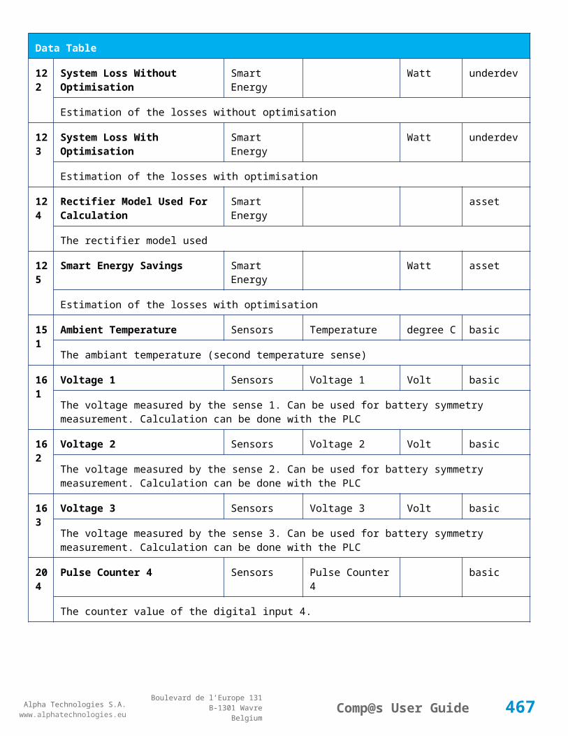
Alpha Technologies S.A.www.alphatechnologies.eu
Alpha Technologies S.A.www.alphatechnologies.eu
Comp@s User GuideBoulevard de l’Europe 131
B-1301 WavreBelgium
Control Table
1 This control element adds an event of severity none. The event name is the text written to this control element
512
Add Major Event Generic Events basic
This control element adds an event of severity major. The event name is the text written to this control element
521
Reset Default Names And Groups Generic Renaming basic
This control element resets all the element Names, Groups and Subgroups to default values for this equipment
522
Reset Default Names And Groups Recursive Generic Renaming basic
This control element resets all the element Names, Groups and Subgroups to default values for this equipment and all sub equipments
7.4.2 ADIO 8
Device Information
Name ADIO 8
Short Description
Standard I/O module D9 ACR5 LVD PLD DCR2
Long Description
I/O module with 9 digital inputs, 5 relays for AC, Low Voltage Disconnection, Partial Load Disconnection and 2 relays for outputs
Hardware Reference
9413 060 05081
Software Reference
SOFT 000096 XX
Equipment Type System Extension
ETSI Level /site/sensors_and_actuators
Description Table
Id Name Group SubGroup License
1 Product Name Description Product Info basic
The commercial name of the extension card.
2 Hardware Reference Description Product Info basic
The hardware refence
467

Alpha Technologies S.A.www.alphatechnologies.eu
Alpha Technologies S.A.www.alphatechnologies.eu
Comp@s User GuideBoulevard de l’Europe 131
B-1301 WavreBelgium
Description Table
3 Hardware Revision Description Product Info basic
The hardware revision
4 Software Reference Description Product Info basic
The software reference
6 Serial Number Description Product Info basic
The serial number.
8 Manufacturing Date Description Product Info basic
The production date.
11 Description Description Custom Description basic
A free text zone to write a system description
12 Reference Description Custom Description basic
A free text zone to write the customer reference of the system
Alarm Table
Id Name Group SubGroup Severity Type (Level) Set/Clear Delay
71 Digital Input 1 Digital Inputs Digital Input 1 warning (0) 5 / 2
The name of the digital input 1 alarm.
72 Digital Input 2 Digital Inputs Digital Input 2 warning (0) 5 / 2
The name of the digital input 2 alarm.
73 Digital Input 3 Digital Inputs Digital Input 3 warning (0) 5 / 2
The name of the digital input 3 alarm.
74 Digital Input 4 Digital Inputs Digital Input 4 warning (0) 5 / 2
The name of the digital input 4 alarm.
75 Digital Input 5 Digital Inputs Digital Input 5 warning (0) 5 / 2
The name of the digital input 5 alarm.
76 Digital Input 6 Digital Inputs Digital Input 6 warning (0) 5 / 2
468
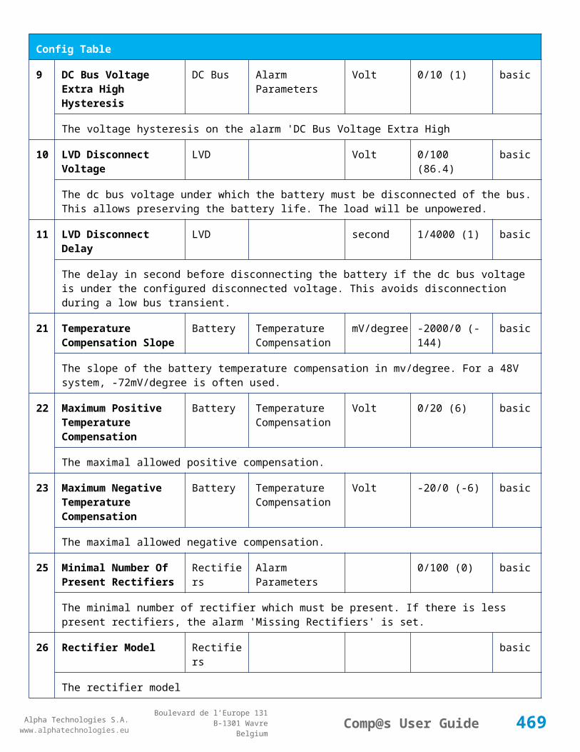
Alpha Technologies S.A.www.alphatechnologies.eu
Alpha Technologies S.A.www.alphatechnologies.eu
Comp@s User GuideBoulevard de l’Europe 131
B-1301 WavreBelgium
Alarm Table
The name of the digital input 6 alarm.
77 Digital Input 7 Digital Inputs Digital Input 7 warning (0) 5 / 2
The name of the digital input 7 alarm.
78 Digital Input 8 Digital Inputs Digital Input 8 warning (0) 5 / 2
The name of the digital input 8 alarm.
79 Digital Input 9 Digital Inputs Digital Input 9 warning (0) 5 / 2
The name of the digital input 9 alarm.
80 Digital Input 10 Digital Inputs Digital Input 10 warning (0) 5 / 2
The name of the digital input 10 alarm.
81 Digital Input 11 Digital Inputs Digital Input 11 warning (0) 5 / 2
The name of the digital input 11 alarm.
82 Digital Input 12 Digital Inputs Digital Input 12 warning (0) 5 / 2
The name of the digital input 12 alarm.
Data Table
Id Name Group SubGroup Unit License
1 Temperature 1 Temperature Sensors Temperature 1 degree C basic
Temperature Measurement 1
71 Digital Input 1 State Digital Inputs Digital Input 1 basic
The state of the digital input
72 Digital Input 2 State Digital Inputs Digital Input 2 basic
The state of the digital input
73 Digital Input 3 State Digital Inputs Digital Input 3 basic
The state of the digital input
74 Digital Input 4 State Digital Inputs Digital Input 4 basic
The state of the digital input
75 Digital Input 5 State Digital Inputs Digital Input 5 basic
469
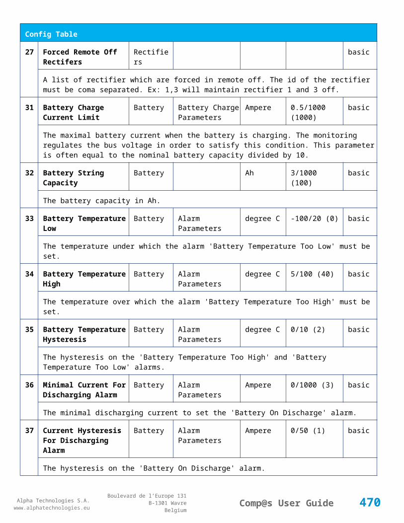
Alpha Technologies S.A.www.alphatechnologies.eu
Alpha Technologies S.A.www.alphatechnologies.eu
Comp@s User GuideBoulevard de l’Europe 131
B-1301 WavreBelgium
Data Table
The state of the digital input
76 Digital Input 6 State Digital Inputs Digital Input 6 basic
The state of the digital input
77 Digital Input 7 State Digital Inputs Digital Input 7 basic
The state of the digital input
78 Digital Input 8 State Digital Inputs Digital Input 8 basic
The state of the digital input
79 Digital Input 9 State Digital Inputs Digital Input 9 basic
The state of the digital input
80 Digital Input 10 State Digital Inputs Digital Input 10 basic
The state of the digital input
81 Digital Input 11 State Digital Inputs Digital Input 11 basic
The state of the digital input
82 Digital Input 12 State Digital Inputs Digital Input 12 basic
The state of the digital input
101 Voltage 5V 1 Voltage Sensors Voltage 5V 1 mVolt basic
Voltage Measurement 5V 1
102 Voltage 5V 2 Voltage Sensors Voltage 5V 2 mVolt basic
Voltage Measurement 5V 2
111 Current 4-20mA 1 Current 4-20mA Sensor Current 4-20mA 1 mAmpere basic
Current 4-20mA Sensor 1
112 Current 4-20mA 2 Current 4-20mA Sensor Current 4-20mA 2 mAmpere basic
Current 4-20mA Sensor 2
Config Table
Id Name Group SubGroup Unit Range: Min/Max (default)
License
71 Digital Input 1 Name Digital Digital Input 1 Digital Inputs basic
470

Alpha Technologies S.A.www.alphatechnologies.eu
Alpha Technologies S.A.www.alphatechnologies.eu
Comp@s User GuideBoulevard de l’Europe 131
B-1301 WavreBelgium
Config Table
Inputs
The name of the digital input 1.
72 Digital Input 1 Normally Closed
Digital Inputs
Digital Input 1 True/False (True) basic
True/False value defining if the digital input 1 is normally closed. If this digital input is not in this default state, the related alarm is set.
73 Digital Input 2 Name Digital Inputs
Digital Input 2 Digital Inputs basic
The name of the digital input 2.
74 Digital Input 2 Normally Closed
Digital Inputs
Digital Input 2 True/False (True) basic
True/False value defining if the digital input 2 is normally closed. If this digital input is not in this default state, the related alarm is set.
75 Digital Input 3 Name Digital Inputs
Digital Input 3 Digital Inputs basic
The name of the digital input 3.
76 Digital Input 3 Normally Closed
Digital Inputs
Digital Input 3 True/False (True) basic
True/False value defining if the digital input 3 is normally closed. If this digital input is not in this default state, the related alarm is set.
77 Digital Input 4 Name Digital Inputs
Digital Input 4 Digital Inputs basic
The name of the digital input 4.
78 Digital Input 4 Normally Closed
Digital Inputs
Digital Input 4 True/False (True) basic
True/False value defining if the digital input 4 is normally closed. If this digital input is not in this default state, the related alarm is set.
79 Digital Input 5 Name Digital Inputs
Digital Input 5 Digital Inputs basic
The name of the digital input 5.
80 Digital Input 5 Normally Closed
Digital Inputs
Digital Input 5 True/False (True) basic
True/False value defining if the digital input 5 is normally closed. If this digital input is not in this default state, the related alarm is set.
471

Alpha Technologies S.A.www.alphatechnologies.eu
Alpha Technologies S.A.www.alphatechnologies.eu
Comp@s User GuideBoulevard de l’Europe 131
B-1301 WavreBelgium
Config Table
81 Digital Input 6 Name Digital Inputs
Digital Input 6 Digital Inputs basic
The name of the digital input 6.
82 Digital Input 6 Normally Closed
Digital Inputs
Digital Input 6 True/False (True) basic
True/False value defining if the digital input 6 is normally closed. If this digital input is not in this default state, the related alarm is set.
83 Digital Input 7 Name Digital Inputs
Digital Input 7 Digital Inputs basic
The name of the digital input 7.
84 Digital Input 7 Normally Closed
Digital Inputs
Digital Input 7 True/False (True) basic
True/False value defining if the digital input 7 is normally closed. If this digital input is not in this default state, the related alarm is set.
85 Digital Input 8 Name Digital Inputs
Digital Input 8 Digital Inputs basic
The name of the digital input 8.
86 Digital Input 8 Normally Closed
Digital Inputs
Digital Input 8 True/False (True) basic
True/False value defining if the digital input 8 is normally closed. If this digital input is not in this default state, the related alarm is set.
87 Digital Input 9 Name Digital Inputs
Digital Input 9 Digital Inputs basic
The name of the digital input 9.
88 Digital Input 9 Normally Closed
Digital Inputs
Digital Input 9 True/False (True) basic
True/False value defining if the digital input 9 is normally closed. If this digital input is not in this default state, the related alarm is set.
89 Digital Input 10 Name Digital Inputs
Digital Input 10 Digital Inputs basic
The name of the digital input 10.
90 Digital Input 10 Normally Closed
Digital Inputs
Digital Input 10 True/False (True) basic
True/False value defining if the digital input 10 is normally closed. If this digital input is not in this default state, the related alarm is set.
472

Alpha Technologies S.A.www.alphatechnologies.eu
Alpha Technologies S.A.www.alphatechnologies.eu
Comp@s User GuideBoulevard de l’Europe 131
B-1301 WavreBelgium
Config Table
91 Digital Input 11 Name Digital Inputs
Digital Input 11 Digital Inputs basic
The name of the digital input 11.
92 Digital Input 11 Normally Closed
Digital Inputs
Digital Input 11 True/False (True) basic
True/False value defining if the digital input 11 is normally closed. If this digital input is not in this default state, the related alarm is set.
93 Digital Input 12 Name Digital Inputs
Digital Input 12 Digital Inputs basic
The name of the digital input 12.
94 Digital Input 12 Normally Closed
Digital Inputs
Digital Input 12 True/False (True) basic
True/False value defining if the digital input 12 is normally closed. If this digital input is not in this default state, the related alarm is set.
121
Relay 1 Change State Boolan Condition
Relays Relay 1 (False) basic
Relay 1 Boolean Condition
122
Relay 1 Normal State Relays Relay 1 (Energized / De-energized)
basic
Normal state of the relay 1: Energized/De-energized.
123
Relay 2 Change State Boolan Condition
Relays Relay 2 (False) basic
Relay 2 Boolean Condition
124
Relay 2 Normal State Relays Relay 2 (Energized / De-energized)
basic
Normal state of the relay 2: Energized/De-energized.
125
Relay 3 Change State Boolan Condition
Relays Relay 3 (False) basic
Relay 3 Boolean Condition
126
Relay 3 Normal State Relays Relay 3 (Energized / De-energized)
basic
Normal state of the relay 3: Energized/De-energized.
127
Relay 4 Change State Boolan Condition
Relays Relay 4 (False) basic
473

Alpha Technologies S.A.www.alphatechnologies.eu
Alpha Technologies S.A.www.alphatechnologies.eu
Comp@s User GuideBoulevard de l’Europe 131
B-1301 WavreBelgium
Config Table
Relay 4 Boolean Condition
128
Relay 4 Normal State Relays Relay 4 (Energized / De-energized)
basic
Normal state of the relay 4: Energized/De-energized.
129
Relay 5 Change State Boolan Condition
Relays Relay 5 (False) basic
Relay 5 Boolean Condition
130
Relay 5 Normal State Relays Relay 5 (Energized / De-energized)
basic
Normal state of the relay 5: Energized/De-energized.
131
Relay 6 Change State Boolan Condition
Relays Relay 6 (False) basic
Relay 6 Boolean Condition
132
Relay 6 Normal State Relays Relay 6 (Energized / De-energized)
basic
Normal state of the relay 6: Energized/De-energized.
133
Relay 7 Change State Boolan Condition
Relays Relay 7 (False) basic
Relay 7 Boolean Condition
134
Relay 7 Normal State Relays Relay 7 (Energized / De-energized)
basic
Normal state of the relay 7: Energized/De-energized.
135
Relay 8 Change State Boolan Condition
Relays Relay 8 (False) basic
Relay 8 Boolean Condition
136
Relay 8 Normal State Relays Relay 8 (Energized / De-energized)
basic
Normal state of the relay 8: Energized/De-energized.
137
Relay 9 Change State Boolan Condition
Relays Relay 9 (False) basic
Relay 9 Boolean Condition
138
Relay 9 Normal State Relays Relay 9 (Energized / De-energized)
basic
474

Alpha Technologies S.A.www.alphatechnologies.eu
Alpha Technologies S.A.www.alphatechnologies.eu
Comp@s User GuideBoulevard de l’Europe 131
B-1301 WavreBelgium
Config Table
Normal state of the relay 9: Energized/De-energized.
139
Relay 10 Change State Boolan Condition
Relays Relay 10 (False) basic
Relay 10 Boolean Condition
140
Relay 10 Normal State Relays Relay 10 (Energized / De-energized)
basic
Normal state of the relay 10: Energized/De-energized.
521
Read Access User Numbers
Generic Allowed Users (1,2,3,4,5) basic
The list of the user numbers which have read access to this equipment. The user numbers are coma separated. The accepted user id are 1,2,3,4 and 5. Ex: 1,3,4
522
Write Access User Numbers
Generic Allowed Users () basic
The list of the user numbers which have write access to this equipment. This means that these users can modify the configuration element, the alarm settings and use the control elements. The user numbers are coma separated. The accepted user ids are 1,2,3,4 and 5. Ex: 1,3,4
601
Event Table Length Generic Events 10/4000 (100) basic
The maximum length of the table. The value must be comprised between 10 and 4000
901
Number Of PLC Data PLC (0) plc
The number of PLC data. Every equipment can manage up to 20 user programmable data. Data elements are automatically added in the data table. Configuration parameters are added to set the PLC Data Name and the PLC Data Mathematical calculation. In order to use these functionalities, you need a license with the 'PLC' module
902
Number Of PLC Alarm PLC (0) plc
The number of PLC alarm. Every equipment can manage up to 20 user programmable alarms. Alarm elements are automatically added in the alarm table. The alarm parameters are added to set the PLC Alarm Name and the PLC Alarm Boolean condition. In order to use these functionalities, you need a licence with the 'PLC' module
Control Table
Id Name Group SubGroup License
501
Clear My Events Generic Events basic
By writing '1' to this control element, all the events of this equipment will be cleared.
50 Clear All Events Generic Events basic
475

Alpha Technologies S.A.www.alphatechnologies.eu
Alpha Technologies S.A.www.alphatechnologies.eu
Comp@s User GuideBoulevard de l’Europe 131
B-1301 WavreBelgium
Control Table
2 By writing '1' to this control element, all the events of this equipment and all the events of all the sub-equipments will be cleared.
511
Add Event Generic Events basic
This control element adds an event of severity none. The event name is the text written to this control element
512
Add Major Event Generic Events basic
This control element adds an event of severity major. The event name is the text written to this control element
521
Reset Default Names And Groups Generic Renaming basic
This control element resets all the element Names, Groups and Subgroups to default values for this equipment
522
Reset Default Names And Groups Recursive Generic Renaming basic
This control element resets all the element Names, Groups and Subgroups to default values for this equipment and all sub equipments
7.4.3 ADIO 9
Device Information
Name ADIO 9
Short Description Custom I/O module Operanet
Long Description
Hardware Reference 9413 060 05091
Software Reference SOFT 000094 XX
Equipment Type System Extension
ETSI Level /site/sensors_and_actuators
Description Table
Id Name Group SubGroup License
1 Product Name Description Product Info basic
The commercial name of the extension card.
2 Hardware Reference Description Product Info basic
476

Alpha Technologies S.A.www.alphatechnologies.eu
Alpha Technologies S.A.www.alphatechnologies.eu
Comp@s User GuideBoulevard de l’Europe 131
B-1301 WavreBelgium
Description Table
The hardware refence
3 Hardware Revision Description Product Info basic
The hardware revision
4 Software Reference Description Product Info basic
The software reference
6 Serial Number Description Product Info basic
The serial number.
8 Manufacturing Date Description Product Info basic
The production date.
11 Description Description Custom Description basic
A free text zone to write a system description
12 Reference Description Custom Description basic
A free text zone to write the customer reference of the system
Alarm Table
Id Name Group SubGroup Severity Type (Level) Set/Clear Delay
71 Digital Input 1 Digital Inputs Digital Input 1 warning (0) 5 / 2
The name of the digital input 1 alarm.
72 Digital Input 2 Digital Inputs Digital Input 2 warning (0) 5 / 2
The name of the digital input 2 alarm.
73 Digital Input 3 Digital Inputs Digital Input 3 warning (0) 5 / 2
The name of the digital input 3 alarm.
74 Digital Input 4 Digital Inputs Digital Input 4 warning (0) 5 / 2
The name of the digital input 4 alarm.
75 Digital Input 5 Digital Inputs Digital Input 5 warning (0) 5 / 2
The name of the digital input 5 alarm.
76 Digital Input 6 Digital Inputs Digital Input 6 warning (0) 5 / 2
477

Alpha Technologies S.A.www.alphatechnologies.eu
Alpha Technologies S.A.www.alphatechnologies.eu
Comp@s User GuideBoulevard de l’Europe 131
B-1301 WavreBelgium
Alarm Table
The name of the digital input 6 alarm.
77 Digital Input 7 Digital Inputs Digital Input 7 warning (0) 5 / 2
The name of the digital input 7 alarm.
78 Digital Input 8 Digital Inputs Digital Input 8 warning (0) 5 / 2
The name of the digital input 8 alarm.
Data Table
Id Name Group SubGroup Unit License
1 Temperature 1 Temperature Sensors Temperature 1 degree C basic
Temperature Measurement 01
2 Temperature 2 Temperature Sensors Temperature 2 degree C basic
Temperature Measurement 11
3 Temperature 3 Temperature Sensors Temperature 3 degree C basic
Temperature Measurement 21
4 Temperature 4 Temperature Sensors Temperature 4 degree C basic
Temperature Measurement 31
71 Digital Input 1 State Digital Inputs Digital Input 1 basic
The state of the digital input
72 Digital Input 2 State Digital Inputs Digital Input 2 basic
The state of the digital input
73 Digital Input 3 State Digital Inputs Digital Input 3 basic
The state of the digital input
74 Digital Input 4 State Digital Inputs Digital Input 4 basic
The state of the digital input
75 Digital Input 5 State Digital Inputs Digital Input 5 basic
The state of the digital input
76 Digital Input 6 State Digital Inputs Digital Input 6 basic
478

Alpha Technologies S.A.www.alphatechnologies.eu
Alpha Technologies S.A.www.alphatechnologies.eu
Comp@s User GuideBoulevard de l’Europe 131
B-1301 WavreBelgium
Data Table
The state of the digital input
77 Digital Input 7 State Digital Inputs Digital Input 7 basic
The state of the digital input
78 Digital Input 8 State Digital Inputs Digital Input 8 basic
The state of the digital input
91 Voltage 1 Voltage Sensors Voltage 1 Volt basic
Voltage Measurement 1
131 Pulse Counter 1 Digital Inputs Digital Input 1 basic
Energy Consumption Counter 1
132 Pulse Counter 2 Digital Inputs Digital Input 2 basic
Energy Consumption Counter 2
133 Pulse Counter 3 Digital Inputs Digital Input 3 basic
Energy Consumption Counter 3
134 Pulse Counter 4 Digital Inputs Digital Input 4 basic
Energy Consumption Counter 4
Config Table
Id Name Group SubGroup Unit Range: Min/Max (default)
License
71 Digital Input 1 Name Digital Inputs Digital Input 1 Digital Inputs basic
The name of the digital input 1.
72 Digital Input 1 Normally Closed
Digital Inputs Digital Input 1 True/False (True) basic
True/False value defining if the digital input 1 is normally closed. If this digital input is not in this default state, the related alarm is set.
73 Digital Input 2 Name Digital Inputs Digital Input 2 Digital Inputs basic
The name of the digital input 2.
74 Digital Input 2 Normally Closed
Digital Inputs Digital Input 2 True/False (True) basic
479

Alpha Technologies S.A.www.alphatechnologies.eu
Alpha Technologies S.A.www.alphatechnologies.eu
Comp@s User GuideBoulevard de l’Europe 131
B-1301 WavreBelgium
Config Table
True/False value defining if the digital input 2 is normally closed. If this digital input is not in this default state, the related alarm is set.
75 Digital Input 3 Name Digital Inputs Digital Input 3 Digital Inputs basic
The name of the digital input 3.
76 Digital Input 3 Normally Closed
Digital Inputs Digital Input 3 True/False (True) basic
True/False value defining if the digital input 3 is normally closed. If this digital input is not in this default state, the related alarm is set.
77 Digital Input 4 Name Digital Inputs Digital Input 4 Digital Inputs basic
The name of the digital input 4.
78 Digital Input 4 Normally Closed
Digital Inputs Digital Input 4 True/False (True) basic
True/False value defining if the digital input 4 is normally closed. If this digital input is not in this default state, the related alarm is set.
79 Digital Input 5 Name Digital Inputs Digital Input 5 Digital Inputs basic
The name of the digital input 5.
80 Digital Input 5 Normally Closed
Digital Inputs Digital Input 5 True/False (True) basic
True/False value defining if the digital input 5 is normally closed. If this digital input is not in this default state, the related alarm is set.
81 Digital Input 6 Name Digital Inputs Digital Input 6 Digital Inputs basic
The name of the digital input 6.
82 Digital Input 6 Normally Closed
Digital Inputs Digital Input 6 True/False (True) basic
True/False value defining if the digital input 6 is normally closed. If this digital input is not in this default state, the related alarm is set.
83 Digital Input 7 Name Digital Inputs Digital Input 7 Digital Inputs basic
The name of the digital input 7.
84 Digital Input 7 Normally Closed
Digital Inputs Digital Input 7 True/False (True) basic
True/False value defining if the digital input 7 is normally closed. If this digital input is not in this default state, the related alarm is set.
85 Digital Input 8 Name Digital Inputs Digital Input 8 Digital Inputs basic
480
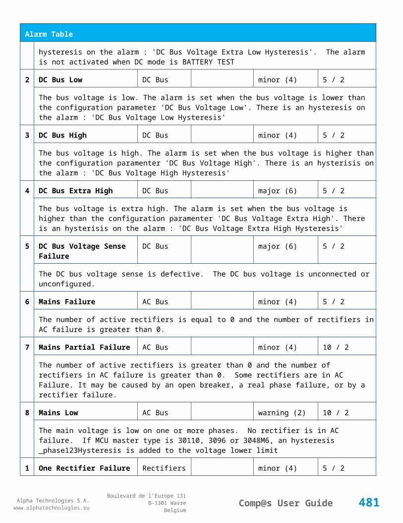
Alpha Technologies S.A.www.alphatechnologies.eu
Alpha Technologies S.A.www.alphatechnologies.eu
Comp@s User GuideBoulevard de l’Europe 131
B-1301 WavreBelgium
Config Table
The name of the digital input 8.
86 Digital Input 8 Normally Closed
Digital Inputs Digital Input 8 True/False (True) basic
True/False value defining if the digital input 8 is normally closed. If this digital input is not in this default state, the related alarm is set.
521
Read Access User Numbers
Generic Allowed Users (1,2,3,4,5) basic
The list of the user numbers which have read access to this equipment. The user numbers are coma separated. The accepted user id are 1,2,3,4 and 5. Ex: 1,3,4
522
Write Access User Numbers
Generic Allowed Users () basic
The list of the user numbers which have write access to this equipment. This means that these users can modify the configuration element, the alarm settings and use the control elements. The user numbers are coma separated. The accepted user ids are 1,2,3,4 and 5. Ex: 1,3,4
601
Event Table Length Generic Events 10/4000 (100) basic
The maximum length of the table. The value must be comprised between 10 and 4000
901
Number Of PLC Data PLC (0) plc
The number of PLC data. Every equipment can manage up to 20 user programmable data. Data elements are automatically added in the data table. Configuration parameters are added to set the PLC Data Name and the PLC Data Mathematical calculation. In order to use these functionalities, you need a license with the 'PLC' module
902
Number Of PLC Alarm PLC (0) plc
The number of PLC alarm. Every equipment can manage up to 20 user programmable alarms. Alarm elements are automatically added in the alarm table. The alarm parameters are added to set the PLC Alarm Name and the PLC Alarm Boolean condition. In order to use these functionalities, you need a licence with the 'PLC' module
Control Table
Id Name Group SubGroup License
101
Set Pulse Counter 1 Pulse Counter Pulse Counter 1 basic
Set Counter 01 Value
102
Set Pulse Counter 2 Pulse Counter Pulse Counter 2 basic
Set Counter 11 Value
10 Set Pulse Counter 3 Pulse Counter Pulse Counter 3 basic
481

Alpha Technologies S.A.www.alphatechnologies.eu
Alpha Technologies S.A.www.alphatechnologies.eu
Comp@s User GuideBoulevard de l’Europe 131
B-1301 WavreBelgium
Control Table
3 Set Counter 21 Value
104
Set Pulse Counter 4 Pulse Counter Pulse Counter 4 basic
Set Counter 31 Value
501
Clear My Events Generic Events basic
By writing '1' to this control element, all the events of this equipment will be cleared.
502
Clear All Events Generic Events basic
By writing '1' to this control element, all the events of this equipment and all the events of all the sub-equipments will be cleared.
511
Add Event Generic Events basic
This control element adds an event of severity none. The event name is the text written to this control element
512
Add Major Event Generic Events basic
This control element adds an event of severity major. The event name is the text written to this control element
521
Reset Default Names And Groups Generic Renaming basic
This control element resets all the element Names, Groups and Subgroups to default values for this equipment
522
Reset Default Names And Groups Recursive Generic Renaming basic
This control element resets all the element Names, Groups and Subgroups to default values for this equipment and all sub equipments
7.4.4 ADIO 10
Device Information
Name ADIO 10
Short Description
Standard I/O module DC systems used as standard IO module
Long Description
I/O module with 2 inputs for temperature measurement, 4 voltage measurements, 2 current measurements, 8 digital inputs and 8 relays
Hardware Reference
9413 060 05101
Software Reference
SOFT 000099 XX
482

Alpha Technologies S.A.www.alphatechnologies.eu
Alpha Technologies S.A.www.alphatechnologies.eu
Comp@s User GuideBoulevard de l’Europe 131
B-1301 WavreBelgium
Device Information
Equipment Type System Extension
ETSI Level /site/sensors_and_actuators
Description Table
Id Name Group SubGroup License
1 Product Name Description Product Info basic
The commercial name of the extension card.
2 Hardware Reference Description Product Info basic
The hardware refence
3 Hardware Revision Description Product Info basic
The hardware revision
4 Software Reference Description Product Info basic
The software reference
6 Serial Number Description Product Info basic
The serial number.
8 Manufacturing Date Description Product Info basic
The production date.
11 Description Description Custom Description basic
A free text zone to write a system description
12 Reference Description Custom Description basic
A free text zone to write the customer reference of the system
Alarm Table
Id Name Group SubGroup Severity Type (Level) Set/Clear Delay
71 Digital Input 1 Digital Inputs Digital Input 1 warning (0) 5 / 2
The name of the digital input 1 alarm.
72 Digital Input 2 Digital Inputs Digital Input 2 warning (0) 5 / 2
The name of the digital input 2 alarm.
483

Alpha Technologies S.A.www.alphatechnologies.eu
Alpha Technologies S.A.www.alphatechnologies.eu
Comp@s User GuideBoulevard de l’Europe 131
B-1301 WavreBelgium
Alarm Table
73 Digital Input 3 Digital Inputs Digital Input 3 warning (0) 5 / 2
The name of the digital input 3 alarm.
74 Digital Input 4 Digital Inputs Digital Input 4 warning (0) 5 / 2
The name of the digital input 4 alarm.
75 Digital Input 5 Digital Inputs Digital Input 5 warning (0) 5 / 2
The name of the digital input 5 alarm.
76 Digital Input 6 Digital Inputs Digital Input 6 warning (0) 5 / 2
The name of the digital input 6 alarm.
77 Digital Input 7 Digital Inputs Digital Input 7 warning (0) 5 / 2
The name of the digital input 7 alarm.
78 Digital Input 8 Digital Inputs Digital Input 8 warning (0) 5 / 2
The name of the digital input 8 alarm.
Data Table
Id Name Group SubGroup Unit License
1 Temperature 1 Temperature Sensors Temperature 1 degree C basic
Temperature Measurement 1
2 Temperature 2 Temperature Sensors Temperature 2 degree C basic
Temperature Measurement 2
71 Shunt 1 Current Sensors Shunt 1 Ampere basic
Shunt Measurement 1
72 Shunt 2 Current Sensors Shunt 2 Ampere basic
Shunt Measurement 2
91 Voltage 1 Voltage Sensors Voltage 1 Volt basic
Voltage Measurement 1
92 Voltage 2 Voltage Sensors Voltage 2 Volt basic
484

Alpha Technologies S.A.www.alphatechnologies.eu
Alpha Technologies S.A.www.alphatechnologies.eu
Comp@s User GuideBoulevard de l’Europe 131
B-1301 WavreBelgium
Data Table
Voltage Measurement 2
93 Voltage 3 Voltage Sensors Voltage 3 Volt basic
Voltage Measurement 3
94 Voltage 4 Voltage Sensors Voltage 4 Volt basic
Voltage Measurement 4
121 Relay 1 State Relays Relay 1 basic
Actual state of the Relay
123 Relay 2 State Relays Relay 2 basic
Actual state of the Relay
125 Relay 3 State Relays Relay 3 basic
Actual state of the Relay
127 Relay 4 State Relays Relay 4 basic
Actual state of the Relay
129 Relay 5 State Relays Relay 5 basic
Actual state of the Relay
131 Relay 6 State Relays Relay 6 basic
Actual state of the Relay
133 Relay 7 State Relays Relay 7 basic
Actual state of the Relay
135 Relay 8 State Relays Relay 8 basic
Actual state of the Relay
Config Table
Id Name Group SubGroup Unit Range: Min/Max (default)
License
41 Shunt 1 Rating At 60mV
Battery Ampere basic
The rating of the shunt 1 at 60mV.
485

Alpha Technologies S.A.www.alphatechnologies.eu
Alpha Technologies S.A.www.alphatechnologies.eu
Comp@s User GuideBoulevard de l’Europe 131
B-1301 WavreBelgium
Config Table
42 Shunt 2 Rating At 60mV
Battery Ampere basic
The rating of the shunt 2 at 60mV.
71 Digital Input 1 Name Digital Inputs
Digital Input 1 Digital Inputs basic
The name of the digital input 1.
72 Digital Input 1 Normally Closed
Digital Inputs
Digital Input 1 True/False (True) basic
True/False value defining if the digital input 1 is normally closed. If this digital input is not in this default state, the related alarm is set.
73 Digital Input 2 Name Digital Inputs
Digital Input 2 Digital Inputs basic
The name of the digital input 2.
74 Digital Input 2 Normally Closed
Digital Inputs
Digital Input 2 True/False (True) basic
True/False value defining if the digital input 2 is normally closed. If this digital input is not in this default state, the related alarm is set.
75 Digital Input 3 Name Digital Inputs
Digital Input 3 Digital Inputs basic
The name of the digital input 3.
76 Digital Input 3 Normally Closed
Digital Inputs
Digital Input 3 True/False (True) basic
True/False value defining if the digital input 3 is normally closed. If this digital input is not in this default state, the related alarm is set.
77 Digital Input 4 Name Digital Inputs
Digital Input 4 Digital Inputs basic
The name of the digital input 4.
78 Digital Input 4 Normally Closed
Digital Inputs
Digital Input 4 True/False (True) basic
True/False value defining if the digital input 4 is normally closed. If this digital input is not in this default state, the related alarm is set.
79 Digital Input 5 Name Digital Inputs
Digital Input 5 Digital Inputs basic
The name of the digital input 5.
486

Alpha Technologies S.A.www.alphatechnologies.eu
Alpha Technologies S.A.www.alphatechnologies.eu
Comp@s User GuideBoulevard de l’Europe 131
B-1301 WavreBelgium
Config Table
80 Digital Input 5 Normally Closed
Digital Inputs
Digital Input 5 True/False (True) basic
True/False value defining if the digital input 5 is normally closed. If this digital input is not in this default state, the related alarm is set.
81 Digital Input 6 Name Digital Inputs
Digital Input 6 Digital Inputs basic
The name of the digital input 6.
82 Digital Input 6 Normally Closed
Digital Inputs
Digital Input 6 True/False (True) basic
True/False value defining if the digital input 6 is normally closed. If this digital input is not in this default state, the related alarm is set.
83 Digital Input 7 Name Digital Inputs
Digital Input 7 Digital Inputs basic
The name of the digital input 7.
84 Digital Input 7 Normally Closed
Digital Inputs
Digital Input 7 True/False (True) basic
True/False value defining if the digital input 7 is normally closed. If this digital input is not in this default state, the related alarm is set.
85 Digital Input 8 Name Digital Inputs
Digital Input 8 Digital Inputs basic
The name of the digital input 8.
86 Digital Input 8 Normally Closed
Digital Inputs
Digital Input 8 True/False (True) basic
True/False value defining if the digital input 8 is normally closed. If this digital input is not in this default state, the related alarm is set.
121
Relay 1 Change State Boolan Condition
Relays Relay 1 (False) basic
Relay 1 Boolean Condition
122
Relay 1 Normal State Relays Relay 1 (Energized / De-energized)
basic
Relay 1 Normal State
123
Relay 2 Change State Boolan Condition
Relays Relay 2 (False) basic
Relay 2 Boolean Condition
487

Alpha Technologies S.A.www.alphatechnologies.eu
Alpha Technologies S.A.www.alphatechnologies.eu
Comp@s User GuideBoulevard de l’Europe 131
B-1301 WavreBelgium
Config Table
124
Relay 2 Normal State Relays Relay 2 (Energized / De-energized)
basic
Relay 2 Normal State
125
Relay 3 Change State Boolan Condition
Relays Relay 3 (False) basic
Relay 3 Boolean Condition
126
Relay 3 Normal State Relays Relay 3 (Energized / De-energized)
basic
Relay 3 Normal State
127
Relay 4 Change State Boolan Condition
Relays Relay 4 (False) basic
Relay 4 Boolean Condition
128
Relay 4 Normal State Relays Relay 4 (Energized / De-energized)
basic
Relay 4 Normal State
129
Relay 5 Change State Boolan Condition
Relays Relay 5 (False) basic
Relay 5 Boolean Condition
130
Relay 5 Normal State Relays Relay 5 (Energized / De-energized)
basic
Relay 5 Normal State
131
Relay 6 Change State Boolan Condition
Relays Relay 6 (False) basic
Relay 6 Boolean Condition
132
Relay 6 Normal State Relays Relay 6 (Energized / De-energized)
basic
Relay 6 Normal State
133
Relay 7 Change State Boolan Condition
Relays Relay 7 (False) basic
Relay 7 Boolean Condition
134
Relay 7 Normal State Relays Relay 7 (Energized / De-energized)
basic
Relay 7 Normal State
488

Alpha Technologies S.A.www.alphatechnologies.eu
Alpha Technologies S.A.www.alphatechnologies.eu
Comp@s User GuideBoulevard de l’Europe 131
B-1301 WavreBelgium
Config Table
135
Relay 8 Change State Boolan Condition
Relays Relay 8 (False) basic
Relay 8 Boolean Condition
136
Relay 8 Normal State Relays Relay 8 (Energized / De-energized)
basic
Relay 8 Normal State
137
Default Digital Output Binary Vector
Relays (0b00000000) basic
This configuration is stored inside the module in case of configuration failure
521
Read Access User Numbers
Generic Allowed Users (1,2,3,4,5) basic
The list of the user numbers which have read access to this equipment. The user numbers are coma separated. The accepted user id are 1,2,3,4 and 5. Ex: 1,3,4
522
Write Access User Numbers
Generic Allowed Users () basic
The list of the user numbers which have write access to this equipment. This means that these users can modify the configuration element, the alarm settings and use the control elements. The user numbers are coma separated. The accepted user ids are 1,2,3,4 and 5. Ex: 1,3,4
601
Event Table Length Generic Events 10/4000 (100) basic
The maximum length of the table. The value must be comprised between 10 and 4000
901
Number Of PLC Data PLC (0) plc
The number of PLC data. Every equipment can manage up to 20 user programmable data. Data elements are automatically added in the data table. Configuration parameters are added to set the PLC Data Name and the PLC Data Mathematical calculation. In order to use these functionalities, you need a license with the 'PLC' module
902
Number Of PLC Alarm PLC (0) plc
The number of PLC alarm. Every equipment can manage up to 20 user programmable alarms. Alarm elements are automatically added in the alarm table. The alarm parameters are added to set the PLC Alarm Name and the PLC Alarm Boolean condition. In order to use these functionalities, you need a licence with the 'PLC' module
Control Table
Id Name Group SubGroup License
11 Calibrate V1 Calibration basic
489

Alpha Technologies S.A.www.alphatechnologies.eu
Alpha Technologies S.A.www.alphatechnologies.eu
Comp@s User GuideBoulevard de l’Europe 131
B-1301 WavreBelgium
Control Table
12 Calibrate V2 Calibration basic
13 Calibrate V3 Calibration basic
14 Calibrate V4 Calibration basic
121
Invert Relay 1 State For X Seconds Relays Relay 1 basic
Generate Pulse on relay
123
Invert Relay 2 State For X Seconds Relays Relay 2 basic
Generate Pulse on relay
125
Invert Relay 3 State For X Seconds Relays Relay 3 basic
Generate Pulse on relay
127
Invert Relay 4 State For X Seconds Relays Relay 4 basic
Generate Pulse on relay
129
Invert Relay 5 State For X Seconds Relays Relay 5 basic
Generate Pulse on relay
131
Invert Relay 6 State For X Seconds Relays Relay 6 basic
Generate Pulse on relay
133
Invert Relay 7 State For X Seconds Relays Relay 7 basic
Generate Pulse on relay
135
Invert Relay 8 State For X Seconds Relays Relay 8 basic
Generate Pulse on relay
501
Clear My Events Generic Events basic
By writing '1' to this control element, all the events of this equipment will be cleared.
502
Clear All Events Generic Events basic
By writing '1' to this control element, all the events of this equipment and all the events of all the sub-equipments will be cleared.
490

Alpha Technologies S.A.www.alphatechnologies.eu
Alpha Technologies S.A.www.alphatechnologies.eu
Comp@s User GuideBoulevard de l’Europe 131
B-1301 WavreBelgium
Control Table
511
Add Event Generic Events basic
This control element adds an event of severity none. The event name is the text written to this control element
512
Add Major Event Generic Events basic
This control element adds an event of severity major. The event name is the text written to this control element
521
Reset Default Names And Groups Generic Renaming basic
This control element resets all the element Names, Groups and Subgroups to default values for this equipment
522
Reset Default Names And Groups Recursive Generic Renaming basic
This control element resets all the element Names, Groups and Subgroups to default values for this equipment and all sub equipments
7.4.5 ADIO 12
Device Information
Name ADIO 12
Short Description ADIO Module
Long Description
Hardware Reference 9413 060 05121
Software Reference SOFT 000121 XX
Equipment Type System Extension
ETSI Level /site/sensors_and_actuators
Description Table
Id Name Group SubGroup License
1 Product Name Description Product Info basic
The commercial name of the extension card.
2 Hardware Reference Description Product Info basic
The hardware refence
3 Hardware Revision Description Product Info basic
491

Alpha Technologies S.A.www.alphatechnologies.eu
Alpha Technologies S.A.www.alphatechnologies.eu
Comp@s User GuideBoulevard de l’Europe 131
B-1301 WavreBelgium
Description Table
The hardware revision
4 Software Reference Description Product Info basic
The software reference
6 Serial Number Description Product Info basic
The serial number.
8 Manufacturing Date Description Product Info basic
The production date.
11 Description Description Custom Description basic
A free text zone to write a system description
12 Reference Description Custom Description basic
A free text zone to write the customer reference of the system
Data Table
Id Name Group SubGroup Unit License
1 Temperature 1 Temperature Sensors Temperature 1 degree C basic
Temperature Measurement 01
2 Temperature 2 Temperature Sensors Temperature 2 degree C basic
Temperature Measurement 11
71 Shunt 1 Current Sensors Shunt 1 Ampere basic
Shunt Measurement 1
72 Shunt 2 Current Sensors Shunt 2 Ampere basic
Shunt Measurement 2
73 Shunt 3 Current Sensors Shunt 3 Ampere basic
Shunt Measurement 3
74 Shunt 4 Current Sensors Shunt 4 Ampere basic
Shunt Measurement 4
492
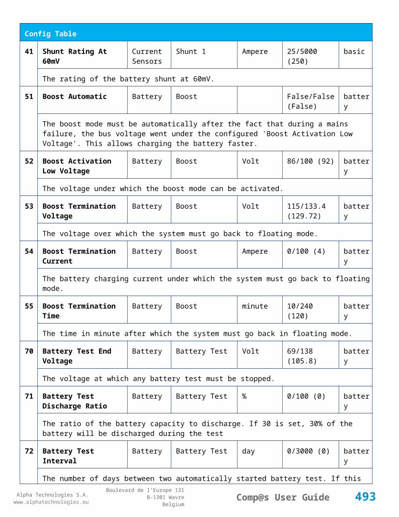
Alpha Technologies S.A.www.alphatechnologies.eu
Alpha Technologies S.A.www.alphatechnologies.eu
Comp@s User GuideBoulevard de l’Europe 131
B-1301 WavreBelgium
Data Table
75 Shunt 5 Current Sensors Shunt 5 Ampere basic
Shunt Measurement 5
76 Shunt 6 Current Sensors Shunt 6 Ampere basic
Shunt Measurement 6
77 Shunt 7 Current Sensors Shunt 7 Ampere basic
Shunt Measurement 7
78 Shunt 8 Current Sensors Shunt 8 Ampere basic
Shunt Measurement 8
91 Voltage 1 Voltage Sensors Voltage 1 Volt basic
Voltage Measurement 01
92 Voltage 2 Voltage Sensors Voltage 2 Volt basic
Voltage Measurement 11
93 Voltage 3 Voltage Sensors Voltage 3 Volt basic
Voltage Measurement 21
94 Voltage 4 Voltage Sensors Voltage 4 Volt basic
Voltage Measurement 31
121 Relay 1 State Relays Relay 1 basic
Actual state of the Relay
123 Relay 2 State Relays Relay 2 basic
Actual state of the Relay
125 Relay 3 State Relays Relay 3 basic
Actual state of the Relay
127 Relay 4 State Relays Relay 4 basic
Actual state of the Relay
129 Relay 5 State Relays Relay 5 basic
Actual state of the Relay
131 Relay 6 State Relays Relay 6 basic
493

Alpha Technologies S.A.www.alphatechnologies.eu
Alpha Technologies S.A.www.alphatechnologies.eu
Comp@s User GuideBoulevard de l’Europe 131
B-1301 WavreBelgium
Data Table
Actual state of the Relay
133 Relay 7 State Relays Relay 7 basic
Actual state of the Relay
135 Relay 8 State Relays Relay 8 basic
Actual state of the Relay
Config Table
Id Name Group SubGroup Unit Range: Min/Max (default)
License
41 Shunt 1 Rating At 60mV
Current Sensors
Shunt 1 Ampere basic
The rating of the shunt 1 at 60mV.
42 Shunt 2 Rating At 60mV
Current Sensors
Shunt 2 Ampere basic
The rating of the shunt 2 at 60mV.
43 Shunt 3 Rating At 60mV
Current Sensors
Shunt 3 Ampere basic
The rating of the shunt 3 at 60mV.
44 Shunt 4 Rating At 60mV
Current Sensors
Shunt 4 Ampere basic
The rating of the shunt 4 at 60mV.
45 Shunt 5 Rating At 60mV
Current Sensors
Shunt 5 Ampere basic
The rating of the shunt 5 at 60mV.
46 Shunt 6 Rating At 60mV
Current Sensors
Shunt 6 Ampere basic
The rating of the shunt 6 at 60mV.
47 Shunt 7 Rating At 60mV
Current Sensors
Shunt 7 Ampere basic
The rating of the shunt 7 at 60mV.
48 Shunt 8 Rating At 60mV
Current Sensors
Shunt 8 Ampere basic
494

Alpha Technologies S.A.www.alphatechnologies.eu
Alpha Technologies S.A.www.alphatechnologies.eu
Comp@s User GuideBoulevard de l’Europe 131
B-1301 WavreBelgium
Config Table
The rating of the shunt 8 at 60mV.
121
Relay 1 Change State Boolan Condition
Relays Relay 1 (False) basic
Relay 1 Boolean Condition
122
Relay 1 Normal State Relays Relay 1 (Energized / De-energized)
basic
Relay 1 Normal State
123
Relay 2 Change State Boolan Condition
Relays Relay 2 (False) basic
Relay 2 Boolean Condition
124
Relay 2 Normal State Relays Relay 2 (Energized / De-energized)
basic
Relay 2 Normal State
125
Relay 3 Change State Boolan Condition
Relays Relay 3 (False) basic
Relay 3 Boolean Condition
126
Relay 3 Normal State Relays Relay 3 (Energized / De-energized)
basic
Relay 3 Normal State
127
Relay 4 Change State Boolan Condition
Relays Relay 4 (False) basic
Relay 4 Boolean Condition
128
Relay 4 Normal State Relays Relay 4 (Energized / De-energized)
basic
Relay 4 Normal State
129
Relay 5 Change State Boolan Condition
Relays Relay 5 (False) basic
Relay 5 Boolean Condition
130
Relay 5 Normal State Relays Relay 5 (Energized / De-energized)
basic
Relay 5 Normal State
131
Relay 6 Change State Boolan Condition
Relays Relay 6 (False) basic
495

Alpha Technologies S.A.www.alphatechnologies.eu
Alpha Technologies S.A.www.alphatechnologies.eu
Comp@s User GuideBoulevard de l’Europe 131
B-1301 WavreBelgium
Config Table
Relay 6 Boolean Condition
132
Relay 6 Normal State Relays Relay 6 (Energized / De-energized)
basic
Relay 6 Normal State
133
Relay 7 Change State Boolan Condition
Relays Relay 7 (False) basic
Relay 7 Boolean Condition
134
Relay 7 Normal State Relays Relay 7 (Energized / De-energized)
basic
Relay 7 Normal State
135
Relay 8 Change State Boolan Condition
Relays Relay 8 (False) basic
Relay 8 Boolean Condition
136
Relay 8 Normal State Relays Relay 8 (Energized / De-energized)
basic
Relay 8 Normal State
137
Default Digital Output Binary Vector
Relays General (0b00000000) basic
This configuration is stored inside the module in case of configuration failure
521
Read Access User Numbers
Generic Allowed Users
(1,2,3,4,5) basic
The list of the user numbers which have read access to this equipment. The user numbers are coma separated. The accepted user id are 1,2,3,4 and 5. Ex: 1,3,4
522
Write Access User Numbers
Generic Allowed Users
() basic
The list of the user numbers which have write access to this equipment. This means that these users can modify the configuration element, the alarm settings and use the control elements. The user numbers are coma separated. The accepted user ids are 1,2,3,4 and 5. Ex: 1,3,4
601
Event Table Length Generic Events 10/4000 (100) basic
The maximum length of the table. The value must be comprised between 10 and 4000
901
Number Of PLC Data PLC (0) plc
The number of PLC data. Every equipment can manage up to 20 user programmable data. Data elements are automatically added in the data table. Configuration parameters are added to set the PLC Data Name and the PLC Data Mathematical calculation. In order to use these functionalities, you need
496

Alpha Technologies S.A.www.alphatechnologies.eu
Alpha Technologies S.A.www.alphatechnologies.eu
Comp@s User GuideBoulevard de l’Europe 131
B-1301 WavreBelgium
Config Table
a license with the 'PLC' module
902
Number Of PLC Alarm PLC (0) plc
The number of PLC alarm. Every equipment can manage up to 20 user programmable alarms. Alarm elements are automatically added in the alarm table. The alarm parameters are added to set the PLC Alarm Name and the PLC Alarm Boolean condition. In order to use these functionalities, you need a licence with the 'PLC' module
Control Table
Id Name Group SubGroup License
101
Set Pulse Counter 1 Pulse Counter basic
Set Counter 1 Value
102
Set Pulse Counter 2 Pulse Counter basic
Set Counter 2 Value
103
Set Pulse Counter 3 Pulse Counter basic
Set Counter 3 Value
104
Set Pulse Counter 4 Pulse Counter basic
Set Counter 4 Value
105
Set Pulse Counter 5 Pulse Counter basic
Set Counter 5 Value
106
Set Pulse Counter 6 Pulse Counter basic
Set Counter 6 Value
107
Set Pulse Counter 7 Pulse Counter basic
Set Counter 7 Value
108
Set Pulse Counter 8 Pulse Counter basic
Set Counter 8 Value
121
Invert Relay 1 State For X Seconds Relays Relay 1 basic
Generate Pulse on relay
123
Invert Relay 2 State For X Seconds Relays Relay 2 basic
Generate Pulse on relay
497

Alpha Technologies S.A.www.alphatechnologies.eu
Alpha Technologies S.A.www.alphatechnologies.eu
Comp@s User GuideBoulevard de l’Europe 131
B-1301 WavreBelgium
Control Table
125
Invert Relay 3 State For X Seconds Relays Relay 3 basic
Generate Pulse on relay
127
Invert Relay 4 State For X Seconds Relays Relay 4 basic
Generate Pulse on relay
129
Invert Relay 5 State For X Seconds Relays Relay 5 basic
Generate Pulse on relay
131
Invert Relay 6 State For X Seconds Relays Relay 6 basic
Generate Pulse on relay
133
Invert Relay 7 State For X Seconds Relays Relay 7 basic
Generate Pulse on relay
135
Invert Relay 8 State For X Seconds Relays Relay 8 basic
Generate Pulse on relay
501
Clear My Events Generic Events basic
By writing '1' to this control element, all the events of this equipment will be cleared.
502
Clear All Events Generic Events basic
By writing '1' to this control element, all the events of this equipment and all the events of all the sub-equipments will be cleared.
511
Add Event Generic Events basic
This control element adds an event of severity none. The event name is the text written to this control element
512
Add Major Event Generic Events basic
This control element adds an event of severity major. The event name is the text written to this control element
521
Reset Default Names And Groups Generic Renaming basic
This control element resets all the element Names, Groups and Subgroups to default values for this equipment
522
Reset Default Names And Groups Recursive Generic Renaming basic
This control element resets all the element Names, Groups and Subgroups to default values for this equipment and all sub equipments
498

Alpha Technologies S.A.www.alphatechnologies.eu
Alpha Technologies S.A.www.alphatechnologies.eu
Comp@s User GuideBoulevard de l’Europe 131
B-1301 WavreBelgium
7.4.6 ADIO 13
Device Information
Name ADIO 13
Short Description ADIO Module
Long Description
Hardware Reference 9413 060 05131
Software Reference SOFT 000122 XX
Equipment Type System Extension
ETSI Level /site/sensors_and_actuators
Description Table
Id Name Group SubGroup License
1 Product Name Description Product Info basic
The commercial name of the extension card.
2 Hardware Reference Description Product Info basic
The hardware refence
3 Hardware Revision Description Product Info basic
The hardware revision
4 Software Reference Description Product Info basic
The software reference
6 Serial Number Description Product Info basic
The serial number.
8 Manufacturing Date Description Product Info basic
The production date.
11 Description Description Custom Description basic
A free text zone to write a system description
12 Reference Description Custom Description basic
A free text zone to write the customer reference of the system
499
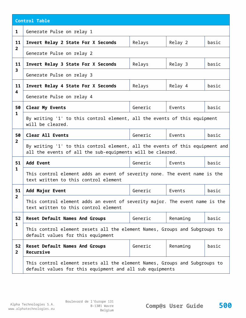
Alpha Technologies S.A.www.alphatechnologies.eu
Alpha Technologies S.A.www.alphatechnologies.eu
Comp@s User GuideBoulevard de l’Europe 131
B-1301 WavreBelgium
Data Table
Id Name Group SubGroup Unit License
11 Hybrid Power Hybrid Watt basic
The Output Power
71 Shunt 1 Current Sensors Shunt 1 Ampere basic
Shunt Measurement 1
72 Shunt 2 Current Sensors Shunt 2 Ampere basic
Shunt Measurement 2
91 Voltage 1 Voltage Sensors Voltage 1 Volt basic
Voltage Measurement 1
201 Wind Direction Wind Sensor degree basic
The wind direction
202 Wind Speed Wind Sensor basic
The wind speed
203 Wind Sensor Status Wind Sensor basic
The wind sensor status
301 MPPT GlobalSet Point Hybrid Watt basic
310 MPPT Value 1 Hybrid Volt basic
311 MPPT Value 2 Hybrid Volt basic
312 MPPT Value 3 Hybrid Volt basic
313 MPPT Value 4 Hybrid Volt basic
314 MPPT Value 5 Hybrid Volt basic
500
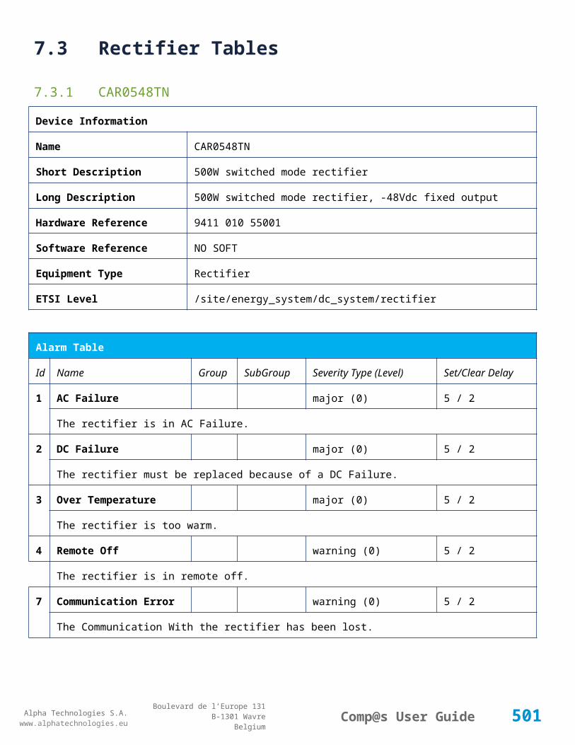
Alpha Technologies S.A.www.alphatechnologies.eu
Alpha Technologies S.A.www.alphatechnologies.eu
Comp@s User GuideBoulevard de l’Europe 131
B-1301 WavreBelgium
Data Table
315 MPPT Value 6 Hybrid Volt basic
316 MPPT Value 7 Hybrid Volt basic
317 MPPT Value 8 Hybrid Volt basic
318 MPPT Value 9 Hybrid Volt basic
319 MPPT Value 10 Hybrid Volt basic
320 MPPT Value 11 Hybrid Volt basic
321 MPPT Value 12 Hybrid Volt basic
322 MPPT Value 13 Hybrid Volt basic
323 MPPT Value 14 Hybrid Volt basic
324 MPPT Value 15 Hybrid Volt basic
325 MPPT Value 16 Hybrid Volt basic
326 MPPT Value 17 Hybrid Volt basic
327 MPPT Value 18 Hybrid Volt basic
328 MPPT Value 19 Hybrid Volt basic
501
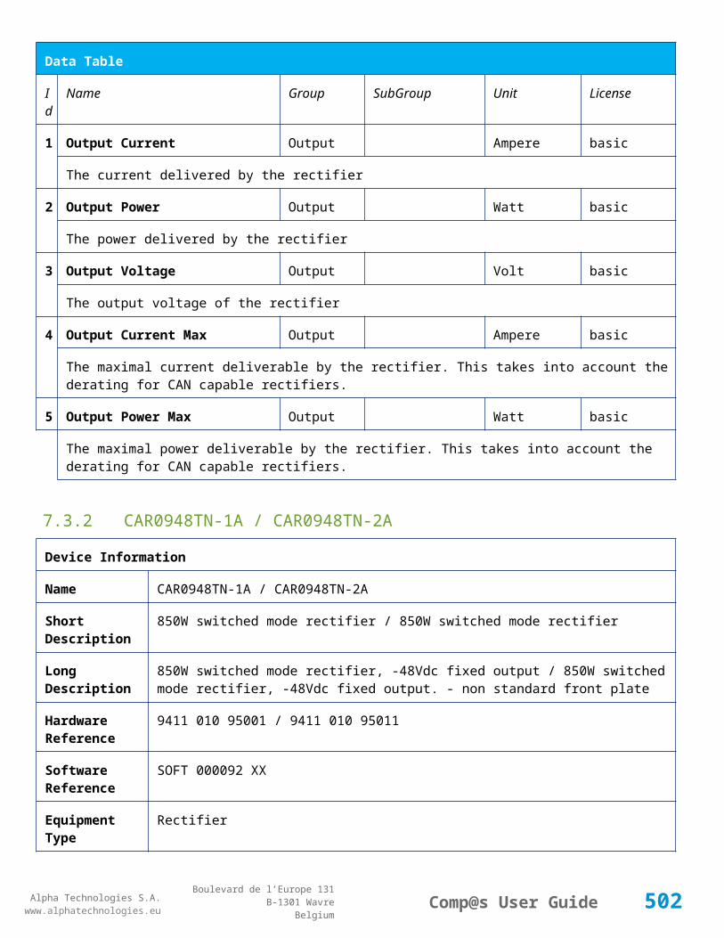
Alpha Technologies S.A.www.alphatechnologies.eu
Alpha Technologies S.A.www.alphatechnologies.eu
Comp@s User GuideBoulevard de l’Europe 131
B-1301 WavreBelgium
Data Table
329 MPPT Value 20 Hybrid Volt basic
Config Table
Id Name Group SubGroup Unit Range: Min/Max (default)
License
41 Shunt 1 Rating At 60mV
Current Sensors
Ampere basic
The rating of the shunt 1 at 60mV.
42 Shunt 2 Rating At 60mV
Current Sensors
Ampere basic
The rating of the shunt 2 at 60mV.
521
Read Access User Numbers
Generic Allowed Users (1,2,3,4,5) basic
The list of the user numbers which have read access to this equipment. The user numbers are coma separated. The accepted user id are 1,2,3,4 and 5. Ex: 1,3,4
522
Write Access User Numbers
Generic Allowed Users () basic
The list of the user numbers which have write access to this equipment. This means that these users can modify the configuration element, the alarm settings and use the control elements. The user numbers are coma separated. The accepted user ids are 1,2,3,4 and 5. Ex: 1,3,4
601
Event Table Length Generic Events 10/4000 (100) basic
The maximum length of the table. The value must be comprised between 10 and 4000
901
Number Of PLC Data
PLC (0) plc
The number of PLC data. Every equipment can manage up to 20 user programmable data. Data elements are automatically added in the data table. Configuration parameters are added to set the PLC Data Name and the PLC Data Mathematical calculation. In order to use these functionalities, you need a license with the 'PLC' module
902
Number Of PLC Alarm
PLC (0) plc
The number of PLC alarm. Every equipment can manage up to 20 user programmable alarms. Alarm elements are automatically added in the alarm table. The alarm parameters are added to set the PLC Alarm Name and the PLC Alarm Boolean condition. In order to use these functionalities, you need a
502
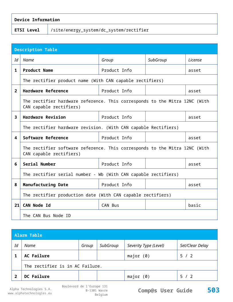
Alpha Technologies S.A.www.alphatechnologies.eu
Alpha Technologies S.A.www.alphatechnologies.eu
Comp@s User GuideBoulevard de l’Europe 131
B-1301 WavreBelgium
Config Table
licence with the 'PLC' module
Control Table
Id Name Group SubGroup License
501
Clear My Events Generic Events basic
By writing '1' to this control element, all the events of this equipment will be cleared.
502
Clear All Events Generic Events basic
By writing '1' to this control element, all the events of this equipment and all the events of all the sub-equipments will be cleared.
511
Add Event Generic Events basic
This control element adds an event of severity none. The event name is the text written to this control element
512
Add Major Event Generic Events basic
This control element adds an event of severity major. The event name is the text written to this control element
521
Reset Default Names And Groups Generic Renaming basic
This control element resets all the element Names, Groups and Subgroups to default values for this equipment
522
Reset Default Names And Groups Recursive Generic Renaming basic
This control element resets all the element Names, Groups and Subgroups to default values for this equipment and all sub equipments
7.4.7 ADIO SP0151
Device Information
Name ADIO SP0151
Short Description Standard I/O module : 6 digital inputs, 6 voltages
Long Description I/O module with 6 digital inputs, 6 voltage measurements (0-3.6Vrms)
Hardware Reference 9413 001 51001
Software Reference SOFT 000119 XX
Equipment Type System Extension
503

Alpha Technologies S.A.www.alphatechnologies.eu
Alpha Technologies S.A.www.alphatechnologies.eu
Comp@s User GuideBoulevard de l’Europe 131
B-1301 WavreBelgium
Device Information
ETSI Level /site/sensors_and_actuators
Description Table
Id Name Group SubGroup License
1 Product Name Description Product Info basic
The commercial name of the extension card.
2 Hardware Reference Description Product Info basic
The hardware refence
3 Hardware Revision Description Product Info basic
The hardware revision
4 Software Reference Description Product Info basic
The software reference
6 Serial Number Description Product Info basic
The serial number.
8 Manufacturing Date Description Product Info basic
The production date.
11 Description Description Custom Description basic
A free text zone to write a system description
12 Reference Description Custom Description basic
A free text zone to write the customer reference of the system
20 TC 1 Reference Track Circuits Track Circuit 1 basic
The name of the track circuit. TCx by default.
21 TC 1 Frequency Track Circuits Track Circuit 1 basic
The frequency of the track circuit.
22 TC 1 Code Track Circuits Track Circuit 1 basic
The coding of the track circuit (AB,CD or EF)
23 TC1 Length Track Circuits Track Circuit 1 basic
504

Alpha Technologies S.A.www.alphatechnologies.eu
Alpha Technologies S.A.www.alphatechnologies.eu
Comp@s User GuideBoulevard de l’Europe 131
B-1301 WavreBelgium
Description Table
The length of the track circuit
40 TC 2 Reference Track Circuits Track Circuit 2 basic
The name of the track circuit. TCx by default.
41 TC 2 Frequency Track Circuits Track Circuit 2 basic
The frequency of the track circuit.
42 TC 2 Code Track Circuits Track Circuit 2 basic
The coding of the track circuit (AB,CD or EF)
43 TC2 Length Track Circuits Track Circuit 2 basic
The length of the track circuit
60 TC 3 Reference Track Circuits Track Circuit 3 basic
The name of the track circuit. TCx by default.
61 TC 3 Frequency Track Circuits Track Circuit 3 basic
The frequency of the track circuit.
62 TC 3 Code Track Circuits Track Circuit 3 basic
The coding of the track circuit (AB,CD or EF)
63 TC3 Length Track Circuits Track Circuit 3 basic
The length of the track circuit
80 TC 4 Reference Track Circuits Track Circuit 4 basic
The name of the track circuit. TCx by default.
81 TC 4 Frequency Track Circuits Track Circuit 4 basic
The frequency of the track circuit.
82 TC 4 Code Track Circuits Track Circuit 4 basic
The coding of the track circuit (AB,CD or EF)
83 TC4 Length Track Circuits Track Circuit 4 basic
The length of the track circuit
100 TC 5 Reference Track Circuits Track Circuit 5 basic
The name of the track circuit. TCx by default.
505

Alpha Technologies S.A.www.alphatechnologies.eu
Alpha Technologies S.A.www.alphatechnologies.eu
Comp@s User GuideBoulevard de l’Europe 131
B-1301 WavreBelgium
Description Table
101 TC 5 Frequency Track Circuits Track Circuit 5 basic
The frequency of the track circuit.
102 TC 5 Code Track Circuits Track Circuit 5 basic
The coding of the track circuit (AB,CD or EF)
103 TC5 Length Track Circuits Track Circuit 5 basic
The length of the track circuit
120 TC 6 Reference Track Circuits Track Circuit 6 basic
The name of the track circuit. TCx by default.
121 TC 6 Frequency Track Circuits Track Circuit 6 basic
The frequency of the track circuit.
122 TC 6 Code Track Circuits Track Circuit 6 basic
The coding of the track circuit (AB,CD or EF)
123 TC6 Length Track Circuits Track Circuit 6 basic
The length of the track circuit
Alarm Table
Id Name Group SubGroup Severity Type (Level) Set/Clear Delay
20 TC 1 Tx Alarm Track Circuits Track Circuit 1 major (0) 5 / 2
The Tx alarm
21 TC 1 Rx Alarm A Track Circuits Track Circuit 1 major (0) 5 / 2
Level A Rx Alarm
22 TC 1 Rx Alarm B Track Circuits Track Circuit 1 minor (0) 5 / 2
Level B Rx Alarm
23 TC 1 Rx Alarm C Track Circuits Track Circuit 1 major (0) 5 / 2
Level C Rx Alarm
24 TC 1 Rx Alarm D Track Circuits Track Circuit 1 warning (0) 5 / 2
Level D Rx Alarm
506

Alpha Technologies S.A.www.alphatechnologies.eu
Alpha Technologies S.A.www.alphatechnologies.eu
Comp@s User GuideBoulevard de l’Europe 131
B-1301 WavreBelgium
Alarm Table
40 TC 2 Tx Alarm Track Circuits Track Circuit 2 major (0) 5 / 2
The Tx alarm
41 TC 2 Rx Alarm A Track Circuits Track Circuit 2 major (0) 5 / 2
Level A Rx Alarm
42 TC 2 Rx Alarm B Track Circuits Track Circuit 2 minor (0) 5 / 2
Level B Rx Alarm
43 TC 2 Rx Alarm C Track Circuits Track Circuit 2 major (0) 5 / 2
Level C Rx Alarm
44 TC 2 Rx Alarm D Track Circuits Track Circuit 2 warning (0) 5 / 2
Level D Rx Alarm
60 TC 3 Tx Alarm Track Circuits Track Circuit 3 major (0) 5 / 2
The Tx alarm
61 TC 3 Rx Alarm A Track Circuits Track Circuit 3 major (0) 5 / 2
Level A Rx Alarm
62 TC 3 Rx Alarm B Track Circuits Track Circuit 3 minor (0) 5 / 2
Level B Rx Alarm
63 TC 3 Rx Alarm C Track Circuits Track Circuit 3 major (0) 5 / 2
Level C Rx Alarm
64 TC 3 Rx Alarm D Track Circuits Track Circuit 3 warning (0) 5 / 2
Level D Rx Alarm
80 TC 4 Tx Alarm Track Circuits Track Circuit 4 major (0) 5 / 2
The Tx alarm
81 TC 4 Rx Alarm A Track Circuits Track Circuit 4 major (0) 5 / 2
Level A Rx Alarm
82 TC 4 Rx Alarm B Track Circuits Track Circuit 4 minor (0) 5 / 2
Level B Rx Alarm
83 TC 4 Rx Alarm C Track Circuits Track Circuit 4 major (0) 5 / 2
507

Alpha Technologies S.A.www.alphatechnologies.eu
Alpha Technologies S.A.www.alphatechnologies.eu
Comp@s User GuideBoulevard de l’Europe 131
B-1301 WavreBelgium
Alarm Table
Level C Rx Alarm
84 TC 4 Rx Alarm D Track Circuits Track Circuit 4 warning (0) 5 / 2
Level D Rx Alarm
100 TC 5 Tx Alarm Track Circuits Track Circuit 5 major (0) 5 / 2
The Tx alarm
101 TC 5 Rx Alarm A Track Circuits Track Circuit 5 major (0) 5 / 2
Level A Rx Alarm
102 TC 5 Rx Alarm B Track Circuits Track Circuit 5 minor (0) 5 / 2
Level B Rx Alarm
103 TC 5 Rx Alarm C Track Circuits Track Circuit 5 major (0) 5 / 2
Level C Rx Alarm
104 TC 5 Rx Alarm D Track Circuits Track Circuit 5 warning (0) 5 / 2
Level D Rx Alarm
120 TC 6 Tx Alarm Track Circuits Track Circuit 6 major (0) 5 / 2
The Tx alarm
121 TC 6 Rx Alarm A Track Circuits Track Circuit 6 major (0) 5 / 2
Level A Rx Alarm
122 TC 6 Rx Alarm B Track Circuits Track Circuit 6 minor (0) 5 / 2
Level B Rx Alarm
123 TC 6 Rx Alarm C Track Circuits Track Circuit 6 major (0) 5 / 2
Level C Rx Alarm
124 TC 6 Rx Alarm D Track Circuits Track Circuit 6 warning (0) 5 / 2
Level D Rx Alarm
Data Table
Id Name Group SubGroup Unit License
20 TC 1 Rx Voltage Track Circuits Track Circuit 1 mVolt basic
508

Alpha Technologies S.A.www.alphatechnologies.eu
Alpha Technologies S.A.www.alphatechnologies.eu
Comp@s User GuideBoulevard de l’Europe 131
B-1301 WavreBelgium
Data Table
The actual measured voltage, on RX
21 TC 1 Tx Level Track Circuits Track Circuit 1 basic
The state of the TX, 1 or 0
22 Status Track Circuits Track Circuit 1 basic
--, Free or Occupied
40 TC 2 Rx Voltage Track Circuits Track Circuit 2 mVolt basic
The actual measured voltage, on RX
41 TC 2 Tx Level Track Circuits Track Circuit 2 basic
The state of the TX, 1 or 0
42 Status Track Circuits Track Circuit 2 basic
--, Free or Occupied
60 TC 3 Rx Voltage Track Circuits Track Circuit 3 mVolt basic
The actual measured voltage, on RX
61 TC 3 Tx Level Track Circuits Track Circuit 3 basic
The state of the TX, 1 or 0
62 Status Track Circuits Track Circuit 3 basic
--, Free or Occupied
80 TC 4 Rx Voltage Track Circuits Track Circuit 4 mVolt basic
The actual measured voltage, on RX
81 TC 4 Tx Level Track Circuits Track Circuit 4 basic
The state of the TX, 1 or 0
82 Status Track Circuits Track Circuit 4 basic
--, Free or Occupied
100 TC 5 Rx Voltage Track Circuits Track Circuit 5 mVolt basic
The actual measured voltage, on RX
101 TC 5 Tx Level Track Circuits Track Circuit 5 basic
The state of the TX, 1 or 0
509
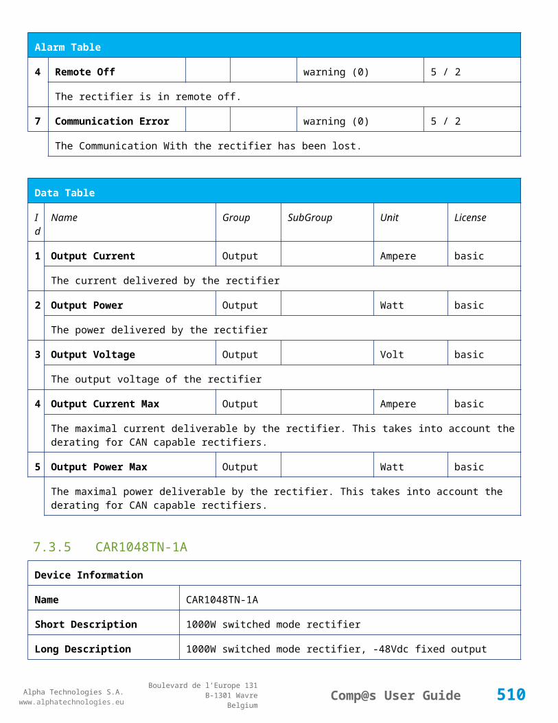
Alpha Technologies S.A.www.alphatechnologies.eu
Alpha Technologies S.A.www.alphatechnologies.eu
Comp@s User GuideBoulevard de l’Europe 131
B-1301 WavreBelgium
Data Table
102 Status Track Circuits Track Circuit 5 basic
--, Free or Occupied
120 TC 6 Rx Voltage Track Circuits Track Circuit 6 mVolt basic
The actual measured voltage, on RX
121 TC 6 Tx Level Track Circuits Track Circuit 6 basic
The state of the TX, 1 or 0
122 Status Track Circuits Track Circuit 6 basic
--, Free or Occupied
Config Table
Id Name Group SubGroup Unit Range: Min/Max (default) License
1 Threshold Overvoltage (A)
Track Circuits
Advanced mVolt basic
2 Threshold Critical (C) Track Circuits
Advanced mVolt basic
3 Threshold TC Busy Track Circuits
Advanced mVolt basic
20 Track Circuit Mode 1 Track Circuits
Track Circuit 1
Tx/Rx,Tx,Rx,Disabled basic
Allows to select what is cabled and should be monitored by the controller
21 Track Circuit 1 Control Level Value
Track Circuits
Track Circuit 1
mVolt basic
Control Level Value
22 Track Circuit 1 Integration Time
Track Circuits
Track Circuit 1
second basic
Integration Time
23 Track Circuit 1 D Delay
Track Circuits
Track Circuit 1
minute basic
510

Alpha Technologies S.A.www.alphatechnologies.eu
Alpha Technologies S.A.www.alphatechnologies.eu
Comp@s User GuideBoulevard de l’Europe 131
B-1301 WavreBelgium
Config Table
TC Delay Time for TC Occupied Alarm (D)
24 Track Circuit 1 Link Track Circuits
Track Circuit 1
basic
Allows to define a link between two TC. The relation is bidirectionnal.
28 Track Circuit 1 Status Enabled
Track Circuits
Track Circuit 1
True/False (True) basic
Allows to enable the monitoring of TC status with ADIO7
40 Track Circuit Mode 2 Track Circuits
Track Circuit 2
Tx/Rx,Tx,Rx,Disabled basic
Allows to select what is cabled and should be monitored by the controller
41 Track Circuit 2 Control Level Value
Track Circuits
Track Circuit 2
mVolt basic
Control Level Value
42 Track Circuit 2 Integration Time
Track Circuits
Track Circuit 2
second basic
Integration Time
43 Track Circuit 2 D Delay
Track Circuits
Track Circuit 2
minute basic
TC Delay Time for TC Occupied Alarm (D)
44 Track Circuit 2 Link Track Circuits
Track Circuit 2
basic
Allows to define a link between two TC. The relation is bidirectionnal.
48 Track Circuit 2 Status Enabled
Track Circuits
Track Circuit 2
True/False (True) basic
Allows to enable the monitoring of TC status with ADIO7
60 Track Circuit Mode 3 Track Circuits
Track Circuit 3
Tx/Rx,Tx,Rx,Disabled basic
Allows to select what is cabled and should be monitored by the controller
61 Track Circuit 3 Control Level Value
Track Circuits
Track Circuit 3
mVolt basic
Control Level Value
62 Track Circuit 3 Integration Time
Track Circuits
Track Circuit 3
second basic
511
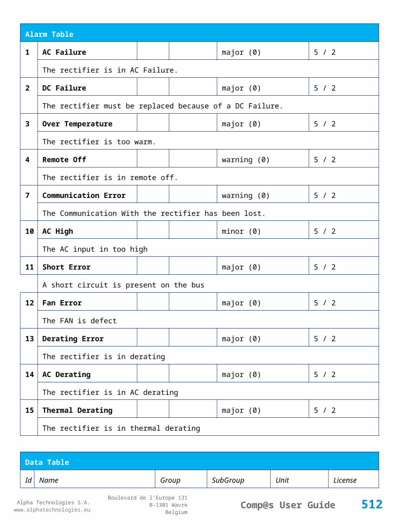
Alpha Technologies S.A.www.alphatechnologies.eu
Alpha Technologies S.A.www.alphatechnologies.eu
Comp@s User GuideBoulevard de l’Europe 131
B-1301 WavreBelgium
Config Table
Integration Time
63 Track Circuit 3 D Delay
Track Circuits
Track Circuit 3
minute basic
TC Delay Time for TC Occupied Alarm (D)
64 Track Circuit 3 Link Track Circuits
Track Circuit 3
basic
Allows to define a link between two TC. The relation is bidirectionnal.
68 Track Circuit 3 Status Enabled
Track Circuits
Track Circuit 3
True/False (True) basic
Allows to enable the monitoring of TC status with ADIO7
80 Track Circuit Mode 4 Track Circuits
Track Circuit 4
Tx/Rx,Tx,Rx,Disabled basic
Allows to select what is cabled and should be monitored by the controller
81 Track Circuit 4 Control Level Value
Track Circuits
Track Circuit 4
mVolt basic
Control Level Value
82 Track Circuit 4 Integration Time
Track Circuits
Track Circuit 4
second basic
Integration Time
83 Track Circuit 4 D Delay
Track Circuits
Track Circuit 4
minute basic
TC Delay Time for TC Occupied Alarm (D)
84 Track Circuit 4 Link Track Circuits
Track Circuit 4
basic
Allows to define a link between two TC. The relation is bidirectionnal.
88 Track Circuit 4 Status Enabled
Track Circuits
Track Circuit 4
True/False (True) basic
Allows to enable the monitoring of TC status with ADIO7
100
Track Circuit Mode 5 Track Circuits
Track Circuit 5
Tx/Rx,Tx,Rx,Disabled basic
Allows to select what is cabled and should be monitored by the controller
101
Track Circuit 5 Control Level Value
Track Circuits
Track Circuit 5
mVolt basic
512

Alpha Technologies S.A.www.alphatechnologies.eu
Alpha Technologies S.A.www.alphatechnologies.eu
Comp@s User GuideBoulevard de l’Europe 131
B-1301 WavreBelgium
Config Table
Control Level Value
102
Track Circuit 5 Integration Time
Track Circuits
Track Circuit 5
second basic
Integration Time
103
Track Circuit 5 D Delay
Track Circuits
Track Circuit 5
minute basic
TC Delay Time for TC Occupied Alarm (D)
104
Track Circuit 5 Link Track Circuits
Track Circuit 5
basic
Allows to define a link between two TC. The relation is bidirectionnal.
108
Track Circuit 5 Status Enabled
Track Circuits
Track Circuit 5
True/False (True) basic
Allows to enable the monitoring of TC status with ADIO7
120
Track Circuit Mode 6 Track Circuits
Track Circuit 6
Tx/Rx,Tx,Rx,Disabled basic
Allows to select what is cabled and should be monitored by the controller
121
Track Circuit 6 Control Level Value
Track Circuits
Track Circuit 6
mVolt basic
Control Level Value
122
Track Circuit 6 Integration Time
Track Circuits
Track Circuit 6
second basic
Integration Time
123
Track Circuit 6 D Delay
Track Circuits
Track Circuit 6
minute basic
TC Delay Time for TC Occupied Alarm (D)
124
Track Circuit 6 Link Track Circuits
Track Circuit 6
basic
Allows to define a link between two TC. The relation is bidirectionnal.
128
Track Circuit 6 Status Enabled
Track Circuits
Track Circuit 6
True/False (True) basic
Allows to enable the monitoring of TC status with ADIO7
521
Read Access User Numbers
Generic Allowed Users
(1,2,3,4,5) basic
513
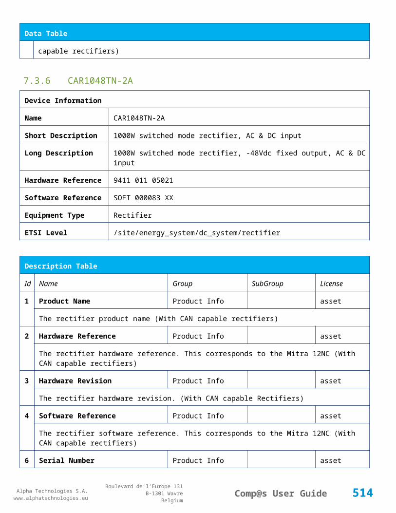
Alpha Technologies S.A.www.alphatechnologies.eu
Alpha Technologies S.A.www.alphatechnologies.eu
Comp@s User GuideBoulevard de l’Europe 131
B-1301 WavreBelgium
Config Table
The list of the user numbers which have read access to this equipment. The user numbers are coma separated. The accepted user id are 1,2,3,4 and 5. Ex: 1,3,4
522
Write Access User Numbers
Generic Allowed Users
() basic
The list of the user numbers which have write access to this equipment. This means that these users can modify the configuration element, the alarm settings and use the control elements. The user numbers are coma separated. The accepted user ids are 1,2,3,4 and 5. Ex: 1,3,4
601
Event Table Length Generic Events 10/4000 (100) basic
The maximum length of the table. The value must be comprised between 10 and 4000
901
Number Of PLC Data PLC (0) plc
The number of PLC data. Every equipment can manage up to 20 user programmable data. Data elements are automatically added in the data table. Configuration parameters are added to set the PLC Data Name and the PLC Data Mathematical calculation. In order to use these functionalities, you need a license with the 'PLC' module
902
Number Of PLC Alarm
PLC (0) plc
The number of PLC alarm. Every equipment can manage up to 20 user programmable alarms. Alarm elements are automatically added in the alarm table. The alarm parameters are added to set the PLC Alarm Name and the PLC Alarm Boolean condition. In order to use these functionalities, you need a licence with the 'PLC' module
Control Table
Id Name Group SubGroup License
501
Clear My Events Generic Events basic
By writing '1' to this control element, all the events of this equipment will be cleared.
502
Clear All Events Generic Events basic
By writing '1' to this control element, all the events of this equipment and all the events of all the sub-equipments will be cleared.
511
Add Event Generic Events basic
This control element adds an event of severity none. The event name is the text written to this control element
512
Add Major Event Generic Events basic
This control element adds an event of severity major. The event name is the text written to this control element
514
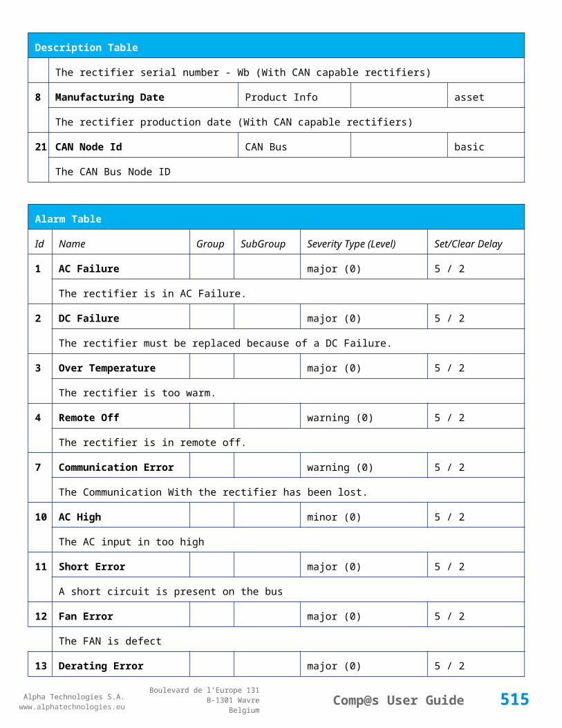
Alpha Technologies S.A.www.alphatechnologies.eu
Alpha Technologies S.A.www.alphatechnologies.eu
Comp@s User GuideBoulevard de l’Europe 131
B-1301 WavreBelgium
Control Table
521
Reset Default Names And Groups Generic Renaming basic
This control element resets all the element Names, Groups and Subgroups to default values for this equipment
522
Reset Default Names And Groups Recursive Generic Renaming basic
This control element resets all the element Names, Groups and Subgroups to default values for this equipment and all sub equipments
999
Test Emulate Changes Test basic
Control used in development phase to test scenario
7.4.8 ADIO SP0155/01
Device Information
Name ADIO SP0155/01
Short Description I/O module : 32 Dig Inputs + 8 Relays
Long Description I/O module with Standard I/O module : 32 Dig Inputs + 8 Relays
Hardware Reference 9413 001 55011
Software Reference SOFT 000124 XX
Equipment Type System Extension
ETSI Level /site/sensors_and_actuators
Description Table
Id Name Group SubGroup License
1 Product Name Description Product Info basic
The commercial name of the extension card.
2 Hardware Reference Description Product Info basic
The hardware refence
3 Hardware Revision Description Product Info basic
The hardware revision
4 Software Reference Description Product Info basic
The software reference
515
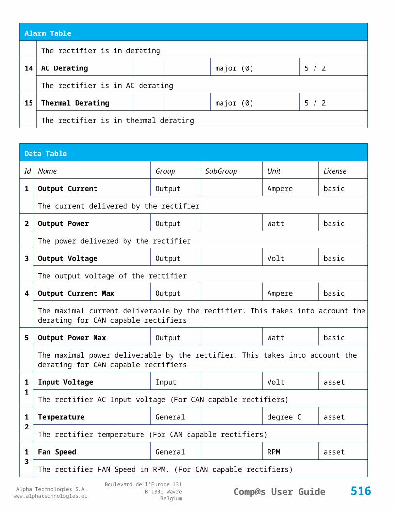
Alpha Technologies S.A.www.alphatechnologies.eu
Alpha Technologies S.A.www.alphatechnologies.eu
Comp@s User GuideBoulevard de l’Europe 131
B-1301 WavreBelgium
Description Table
6 Serial Number Description Product Info basic
The serial number.
8 Manufacturing Date Description Product Info basic
The production date.
11 Description Description Custom Description basic
A free text zone to write a system description
12 Reference Description Custom Description basic
A free text zone to write the customer reference of the system
Alarm Table
Id Name Group SubGroup Severity Type (Level) Set/Clear Delay
101 Digital Input 1 Digital Inputs Digital Input 1 warning (0) 5 / 2
The name of the digital input 1 alarm.
102 Digital Input 2 Digital Inputs Digital Input 2 warning (0) 5 / 2
The name of the digital input 2 alarm.
103 Digital Input 3 Digital Inputs Digital Input 3 warning (0) 5 / 2
The name of the digital input 3 alarm.
104 Digital Input 4 Digital Inputs Digital Input 4 warning (0) 5 / 2
The name of the digital input 4 alarm.
105 Digital Input 5 Digital Inputs Digital Input 5 warning (0) 5 / 2
The name of the digital input 5 alarm.
106 Digital Input 6 Digital Inputs Digital Input 6 warning (0) 5 / 2
The name of the digital input 6 alarm.
107 Digital Input 7 Digital Inputs Digital Input 7 warning (0) 5 / 2
The name of the digital input 7 alarm.
108 Digital Input 8 Digital Inputs Digital Input 8 warning (0) 5 / 2
516

Alpha Technologies S.A.www.alphatechnologies.eu
Alpha Technologies S.A.www.alphatechnologies.eu
Comp@s User GuideBoulevard de l’Europe 131
B-1301 WavreBelgium
Alarm Table
The name of the digital input 8 alarm.
109 Digital Input 9 Digital Inputs Digital Input 9 warning (0) 5 / 2
The name of the digital input 9 alarm.
110 Digital Input 10 Digital Inputs Digital Input 10 warning (0) 5 / 2
The name of the digital input 10 alarm.
111 Digital Input 11 Digital Inputs Digital Input 11 warning (0) 5 / 2
The name of the digital input 11 alarm.
112 Digital Input 12 Digital Inputs Digital Input 12 warning (0) 5 / 2
The name of the digital input 12 alarm.
113 Digital Input 13 Digital Inputs Digital Input 13 warning (0) 5 / 2
The name of the digital input 13 alarm.
114 Digital Input 14 Digital Inputs Digital Input 14 warning (0) 5 / 2
The name of the digital input 14 alarm.
115 Digital Input 15 Digital Inputs Digital Input 15 warning (0) 5 / 2
The name of the digital input 15 alarm.
116 Digital Input 16 Digital Inputs Digital Input 16 warning (0) 5 / 2
The name of the digital input 16 alarm.
117 Digital Input 17 Digital Inputs Digital Input 17 warning (0) 5 / 2
The name of the digital input 17 alarm.
118 Digital Input 18 Digital Inputs Digital Input 18 warning (0) 5 / 2
The name of the digital input 18 alarm.
119 Digital Input 19 Digital Inputs Digital Input 19 warning (0) 5 / 2
The name of the digital input 19 alarm.
120 Digital Input 20 Digital Inputs Digital Input 20 warning (0) 5 / 2
The name of the digital input 20 alarm.
121 Digital Input 21 Digital Inputs Digital Input 21 warning (0) 5 / 2
The name of the digital input 21 alarm.
517
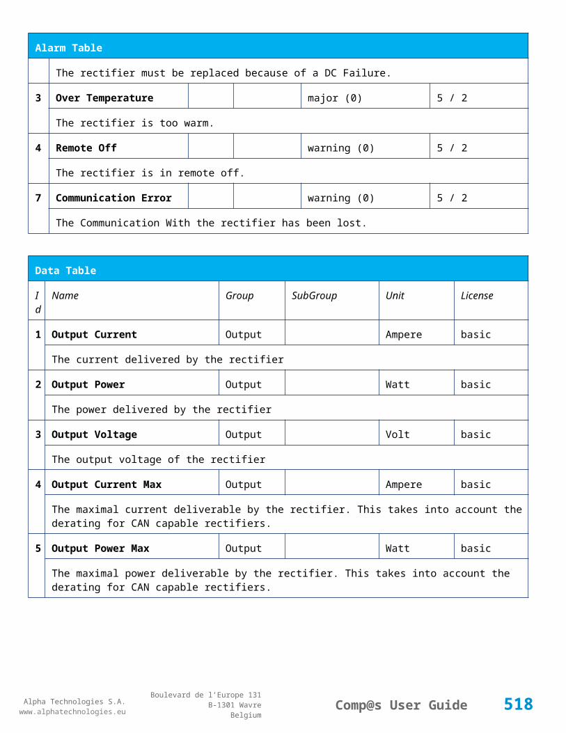
Alpha Technologies S.A.www.alphatechnologies.eu
Alpha Technologies S.A.www.alphatechnologies.eu
Comp@s User GuideBoulevard de l’Europe 131
B-1301 WavreBelgium
Alarm Table
122 Digital Input 22 Digital Inputs Digital Input 22 warning (0) 5 / 2
The name of the digital input 22 alarm.
123 Digital Input 23 Digital Inputs Digital Input 23 warning (0) 5 / 2
The name of the digital input 23 alarm.
124 Digital Input 24 Digital Inputs Digital Input 24 warning (0) 5 / 2
The name of the digital input 24 alarm.
125 Digital Input 25 Digital Inputs Digital Input 25 warning (0) 5 / 2
The name of the digital input 25 alarm.
126 Digital Input 26 Digital Inputs Digital Input 26 warning (0) 5 / 2
The name of the digital input 26 alarm.
127 Digital Input 27 Digital Inputs Digital Input 27 warning (0) 5 / 2
The name of the digital input 27 alarm.
128 Digital Input 28 Digital Inputs Digital Input 28 warning (0) 5 / 2
The name of the digital input 28 alarm.
129 Digital Input 29 Digital Inputs Digital Input 29 warning (0) 5 / 2
The name of the digital input 29 alarm.
130 Digital Input 30 Digital Inputs Digital Input 30 warning (0) 5 / 2
The name of the digital input 30 alarm.
131 Digital Input 31 Digital Inputs Digital Input 31 warning (0) 5 / 2
The name of the digital input 31 alarm.
132 Digital Input 32 Digital Inputs Digital Input 32 warning (0) 5 / 2
The name of the digital input 32 alarm.
Data Table
Id Name Group SubGroup Unit License
101 Digital Input 1 State Digital Inputs Digital Input 1 basic
The state of the digital input
518
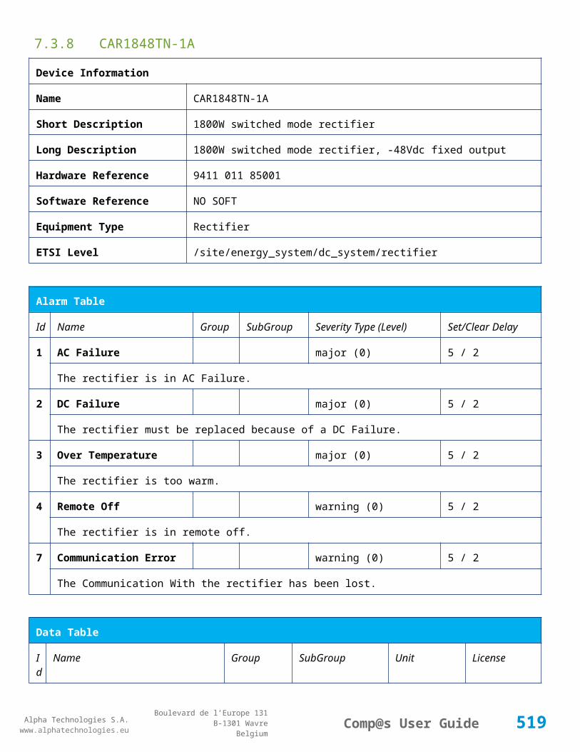
Alpha Technologies S.A.www.alphatechnologies.eu
Alpha Technologies S.A.www.alphatechnologies.eu
Comp@s User GuideBoulevard de l’Europe 131
B-1301 WavreBelgium
Data Table
102 Digital Input 2 State Digital Inputs Digital Input 2 basic
The state of the digital input
103 Digital Input 3 State Digital Inputs Digital Input 3 basic
The state of the digital input
104 Digital Input 4 State Digital Inputs Digital Input 4 basic
The state of the digital input
105 Digital Input 5 State Digital Inputs Digital Input 5 basic
The state of the digital input
106 Digital Input 6 State Digital Inputs Digital Input 6 basic
The state of the digital input
107 Digital Input 7 State Digital Inputs Digital Input 7 basic
The state of the digital input
108 Digital Input 8 State Digital Inputs Digital Input 8 basic
The state of the digital input
109 Digital Input 9 State Digital Inputs Digital Input 9 basic
The state of the digital input
110 Digital Input 10 State Digital Inputs Digital Input 10 basic
The state of the digital input
111 Digital Input 11 State Digital Inputs Digital Input 11 basic
The state of the digital input
112 Digital Input 12 State Digital Inputs Digital Input 12 basic
The state of the digital input
113 Digital Input 13 State Digital Inputs Digital Input 13 basic
The state of the digital input
114 Digital Input 14 State Digital Inputs Digital Input 14 basic
The state of the digital input
115 Digital Input 15 State Digital Inputs Digital Input 15 basic
519

Alpha Technologies S.A.www.alphatechnologies.eu
Alpha Technologies S.A.www.alphatechnologies.eu
Comp@s User GuideBoulevard de l’Europe 131
B-1301 WavreBelgium
Data Table
The state of the digital input
116 Digital Input 16 State Digital Inputs Digital Input 16 basic
The state of the digital input
117 Digital Input 17 State Digital Inputs Digital Input 17 basic
The state of the digital input
118 Digital Input 18 State Digital Inputs Digital Input 18 basic
The state of the digital input
119 Digital Input 19 State Digital Inputs Digital Input 19 basic
The state of the digital input
120 Digital Input 20 State Digital Inputs Digital Input 20 basic
The state of the digital input
121 Digital Input 21 State Digital Inputs Digital Input 21 basic
The state of the digital input
122 Digital Input 22 State Digital Inputs Digital Input 22 basic
The state of the digital input
123 Digital Input 23 State Digital Inputs Digital Input 23 basic
The state of the digital input
124 Digital Input 24 State Digital Inputs Digital Input 24 basic
The state of the digital input
125 Digital Input 25 State Digital Inputs Digital Input 25 basic
The state of the digital input
126 Digital Input 26 State Digital Inputs Digital Input 26 basic
The state of the digital input
127 Digital Input 27 State Digital Inputs Digital Input 27 basic
The state of the digital input
128 Digital Input 28 State Digital Inputs Digital Input 28 basic
The state of the digital input
520

Alpha Technologies S.A.www.alphatechnologies.eu
Alpha Technologies S.A.www.alphatechnologies.eu
Comp@s User GuideBoulevard de l’Europe 131
B-1301 WavreBelgium
Data Table
129 Digital Input 29 State Digital Inputs Digital Input 29 basic
The state of the digital input
130 Digital Input 30 State Digital Inputs Digital Input 30 basic
The state of the digital input
131 Digital Input 31 State Digital Inputs Digital Input 31 basic
The state of the digital input
132 Digital Input 32 State Digital Inputs Digital Input 32 basic
The state of the digital input
301 Relay 1 State Relays Relay 1 basic
Actual state of the Relay
303 Relay 2 State Relays Relay 2 basic
Actual state of the Relay
305 Relay 3 State Relays Relay 3 basic
Actual state of the Relay
307 Relay 4 State Relays Relay 4 basic
Actual state of the Relay
309 Relay 5 State Relays Relay 5 basic
Actual state of the Relay
311 Relay 6 State Relays Relay 6 basic
Actual state of the Relay
313 Relay 7 State Relays Relay 7 basic
Actual state of the Relay
315 Relay 8 State Relays Relay 8 basic
Actual state of the Relay
Config Table
Id Name Group SubGroup Unit Range: Min/Max (default)
License
521

Alpha Technologies S.A.www.alphatechnologies.eu
Alpha Technologies S.A.www.alphatechnologies.eu
Comp@s User GuideBoulevard de l’Europe 131
B-1301 WavreBelgium
Config Table
101
Digital Input 1 Name Digital Inputs
Digital Input 1 Digital Inputs basic
The name of the digital input 1.
102
Digital Input 1 Normally Closed
Digital Inputs
Digital Input 1 True/False (True) basic
True/False value defining if the digital input 1 is normally closed. If this digital input is not in this default state, the related alarm is set.
103
Digital Input 2 Name Digital Inputs
Digital Input 2 Digital Inputs basic
The name of the digital input 2.
104
Digital Input 2 Normally Closed
Digital Inputs
Digital Input 2 True/False (True) basic
True/False value defining if the digital input 2 is normally closed. If this digital input is not in this default state, the related alarm is set.
105
Digital Input 3 Name Digital Inputs
Digital Input 3 Digital Inputs basic
The name of the digital input 3.
106
Digital Input 3 Normally Closed
Digital Inputs
Digital Input 3 True/False (True) basic
True/False value defining if the digital input 3 is normally closed. If this digital input is not in this default state, the related alarm is set.
107
Digital Input 4 Name Digital Inputs
Digital Input 4 Digital Inputs basic
The name of the digital input 4.
108
Digital Input 4 Normally Closed
Digital Inputs
Digital Input 4 True/False (True) basic
True/False value defining if the digital input 4 is normally closed. If this digital input is not in this default state, the related alarm is set.
109
Digital Input 5 Name Digital Inputs
Digital Input 5 Digital Inputs basic
The name of the digital input 5.
110
Digital Input 5 Normally Closed
Digital Inputs
Digital Input 5 True/False (True) basic
True/False value defining if the digital input 5 is normally closed. If this digital input is not in this default state, the related alarm is set.
522

Alpha Technologies S.A.www.alphatechnologies.eu
Alpha Technologies S.A.www.alphatechnologies.eu
Comp@s User GuideBoulevard de l’Europe 131
B-1301 WavreBelgium
Config Table
111
Digital Input 6 Name Digital Inputs
Digital Input 6 Digital Inputs basic
The name of the digital input 6.
112
Digital Input 6 Normally Closed
Digital Inputs
Digital Input 6 True/False (True) basic
True/False value defining if the digital input 6 is normally closed. If this digital input is not in this default state, the related alarm is set.
113
Digital Input 7 Name Digital Inputs
Digital Input 7 Digital Inputs basic
The name of the digital input 7.
114
Digital Input 7 Normally Closed
Digital Inputs
Digital Input 7 True/False (True) basic
True/False value defining if the digital input 7 is normally closed. If this digital input is not in this default state, the related alarm is set.
115
Digital Input 8 Name Digital Inputs
Digital Input 8 Digital Inputs basic
The name of the digital input 8.
116
Digital Input 8 Normally Closed
Digital Inputs
Digital Input 8 True/False (True) basic
True/False value defining if the digital input 8 is normally closed. If this digital input is not in this default state, the related alarm is set.
117
Digital Input 9 Name Digital Inputs
Digital Input 9 Digital Inputs basic
The name of the digital input 9.
118
Digital Input 9 Normally Closed
Digital Inputs
Digital Input 9 True/False (True) basic
True/False value defining if the digital input 9 is normally closed. If this digital input is not in this default state, the related alarm is set.
119
Digital Input 10 Name Digital Inputs
Digital Input 10 Digital Inputs basic
The name of the digital input 10.
120
Digital Input 10 Normally Closed
Digital Inputs
Digital Input 10 True/False (True) basic
True/False value defining if the digital input 10 is normally closed. If this digital input is not in this default state, the related alarm is set.
523
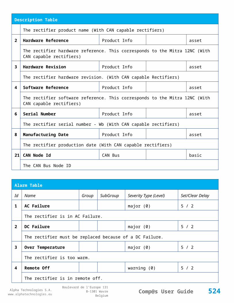
Alpha Technologies S.A.www.alphatechnologies.eu
Alpha Technologies S.A.www.alphatechnologies.eu
Comp@s User GuideBoulevard de l’Europe 131
B-1301 WavreBelgium
Config Table
121
Digital Input 11 Name Digital Inputs
Digital Input 11 Digital Inputs basic
The name of the digital input 11.
122
Digital Input 11 Normally Closed
Digital Inputs
Digital Input 11 True/False (True) basic
True/False value defining if the digital input 11 is normally closed. If this digital input is not in this default state, the related alarm is set.
123
Digital Input 12 Name Digital Inputs
Digital Input 12 Digital Inputs basic
The name of the digital input 12.
124
Digital Input 12 Normally Closed
Digital Inputs
Digital Input 12 True/False (True) basic
True/False value defining if the digital input 12 is normally closed. If this digital input is not in this default state, the related alarm is set.
125
Digital Input 13 Name Digital Inputs
Digital Input 13 Digital Inputs basic
The name of the digital input 13.
126
Digital Input 13 Normally Closed
Digital Inputs
Digital Input 13 True/False (True) basic
True/False value defining if the digital input 13 is normally closed. If this digital input is not in this default state, the related alarm is set.
127
Digital Input 14 Name Digital Inputs
Digital Input 14 Digital Inputs basic
The name of the digital input 14.
128
Digital Input 14 Normally Closed
Digital Inputs
Digital Input 14 True/False (True) basic
True/False value defining if the digital input 14 is normally closed. If this digital input is not in this default state, the related alarm is set.
129
Digital Input 15 Name Digital Inputs
Digital Input 15 Digital Inputs basic
The name of the digital input 15.
130
Digital Input 15 Normally Closed
Digital Inputs
Digital Input 15 True/False (True) basic
True/False value defining if the digital input 15 is normally closed. If this digital input is not in this default state, the related alarm is set.
524
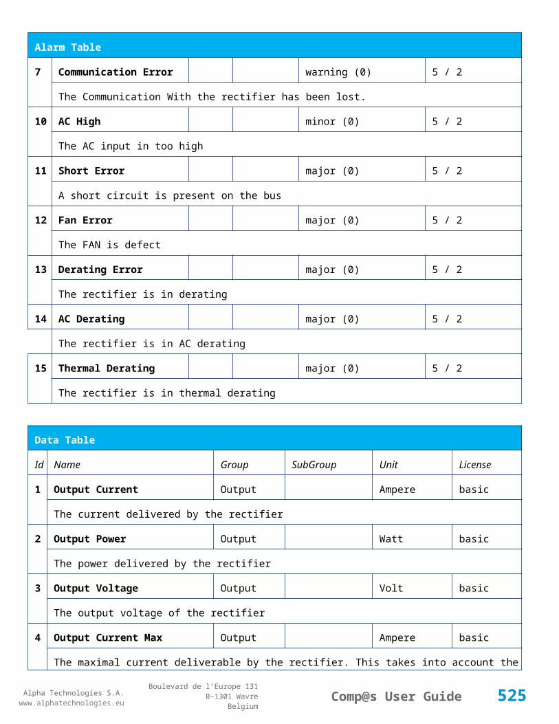
Alpha Technologies S.A.www.alphatechnologies.eu
Alpha Technologies S.A.www.alphatechnologies.eu
Comp@s User GuideBoulevard de l’Europe 131
B-1301 WavreBelgium
Config Table
131
Digital Input 16 Name Digital Inputs
Digital Input 16 Digital Inputs basic
The name of the digital input 16.
132
Digital Input 16 Normally Closed
Digital Inputs
Digital Input 16 True/False (True) basic
True/False value defining if the digital input 16 is normally closed. If this digital input is not in this default state, the related alarm is set.
133
Digital Input 17 Name Digital Inputs
Digital Input 17 Digital Inputs basic
The name of the digital input 17.
134
Digital Input 17 Normally Closed
Digital Inputs
Digital Input 17 True/False (True) basic
True/False value defining if the digital input 17 is normally closed. If this digital input is not in this default state, the related alarm is set.
135
Digital Input 18 Name Digital Inputs
Digital Input 18 Digital Inputs basic
The name of the digital input 18.
136
Digital Input 18 Normally Closed
Digital Inputs
Digital Input 18 True/False (True) basic
True/False value defining if the digital input 18 is normally closed. If this digital input is not in this default state, the related alarm is set.
137
Digital Input 19 Name Digital Inputs
Digital Input 19 Digital Inputs basic
The name of the digital input 19.
138
Digital Input 19 Normally Closed
Digital Inputs
Digital Input 19 True/False (True) basic
True/False value defining if the digital input 19 is normally closed. If this digital input is not in this default state, the related alarm is set.
139
Digital Input 20 Name Digital Inputs
Digital Input 20 Digital Inputs basic
The name of the digital input 20.
140
Digital Input 20 Normally Closed
Digital Inputs
Digital Input 20 True/False (True) basic
True/False value defining if the digital input 20 is normally closed. If this digital input is not in this default state, the related alarm is set.
525

Alpha Technologies S.A.www.alphatechnologies.eu
Alpha Technologies S.A.www.alphatechnologies.eu
Comp@s User GuideBoulevard de l’Europe 131
B-1301 WavreBelgium
Config Table
141
Digital Input 21 Name Digital Inputs
Digital Input 21 Digital Inputs basic
The name of the digital input 21.
142
Digital Input 21 Normally Closed
Digital Inputs
Digital Input 21 True/False (True) basic
True/False value defining if the digital input 21 is normally closed. If this digital input is not in this default state, the related alarm is set.
143
Digital Input 22 Name Digital Inputs
Digital Input 22 Digital Inputs basic
The name of the digital input 22.
144
Digital Input 22 Normally Closed
Digital Inputs
Digital Input 22 True/False (True) basic
True/False value defining if the digital input 22 is normally closed. If this digital input is not in this default state, the related alarm is set.
145
Digital Input 23 Name Digital Inputs
Digital Input 23 Digital Inputs basic
The name of the digital input 23.
146
Digital Input 23 Normally Closed
Digital Inputs
Digital Input 23 True/False (True) basic
True/False value defining if the digital input 23 is normally closed. If this digital input is not in this default state, the related alarm is set.
147
Digital Input 24 Name Digital Inputs
Digital Input 24 Digital Inputs basic
The name of the digital input 24.
148
Digital Input 24 Normally Closed
Digital Inputs
Digital Input 24 True/False (True) basic
True/False value defining if the digital input 24 is normally closed. If this digital input is not in this default state, the related alarm is set.
149
Digital Input 25 Name Digital Inputs
Digital Input 25 Digital Inputs basic
The name of the digital input 25.
150
Digital Input 25 Normally Closed
Digital Inputs
Digital Input 25 True/False (True) basic
True/False value defining if the digital input 25 is normally closed. If this digital input is not in this default state, the related alarm is set.
526

Alpha Technologies S.A.www.alphatechnologies.eu
Alpha Technologies S.A.www.alphatechnologies.eu
Comp@s User GuideBoulevard de l’Europe 131
B-1301 WavreBelgium
Config Table
151
Digital Input 26 Name Digital Inputs
Digital Input 26 Digital Inputs basic
The name of the digital input 26.
152
Digital Input 26 Normally Closed
Digital Inputs
Digital Input 26 True/False (True) basic
True/False value defining if the digital input 26 is normally closed. If this digital input is not in this default state, the related alarm is set.
153
Digital Input 27 Name Digital Inputs
Digital Input 27 Digital Inputs basic
The name of the digital input 27.
154
Digital Input 27 Normally Closed
Digital Inputs
Digital Input 27 True/False (True) basic
True/False value defining if the digital input 27 is normally closed. If this digital input is not in this default state, the related alarm is set.
155
Digital Input 28 Name Digital Inputs
Digital Input 28 Digital Inputs basic
The name of the digital input 28.
156
Digital Input 28 Normally Closed
Digital Inputs
Digital Input 28 True/False (True) basic
True/False value defining if the digital input 28 is normally closed. If this digital input is not in this default state, the related alarm is set.
157
Digital Input 29 Name Digital Inputs
Digital Input 29 Digital Inputs basic
The name of the digital input 29.
158
Digital Input 29 Normally Closed
Digital Inputs
Digital Input 29 True/False (True) basic
True/False value defining if the digital input 29 is normally closed. If this digital input is not in this default state, the related alarm is set.
159
Digital Input 30 Name Digital Inputs
Digital Input 30 Digital Inputs basic
The name of the digital input 30.
160
Digital Input 30 Normally Closed
Digital Inputs
Digital Input 30 True/False (True) basic
True/False value defining if the digital input 30 is normally closed. If this digital input is not in this default state, the related alarm is set.
527
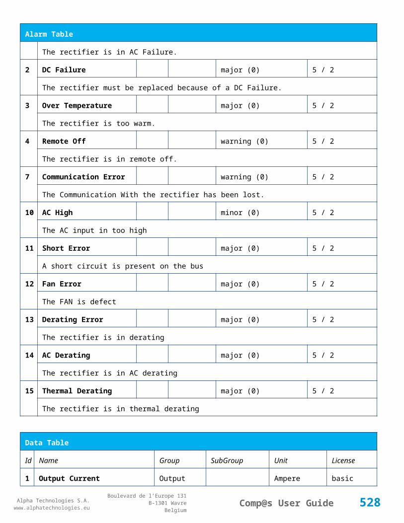
Alpha Technologies S.A.www.alphatechnologies.eu
Alpha Technologies S.A.www.alphatechnologies.eu
Comp@s User GuideBoulevard de l’Europe 131
B-1301 WavreBelgium
Config Table
161
Digital Input 31 Name Digital Inputs
Digital Input 31 Digital Inputs basic
The name of the digital input 31.
162
Digital Input 31 Normally Closed
Digital Inputs
Digital Input 31 True/False (True) basic
True/False value defining if the digital input 31 is normally closed. If this digital input is not in this default state, the related alarm is set.
163
Digital Input 32 Name Digital Inputs
Digital Input 32 Digital Inputs basic
The name of the digital input 32.
164
Digital Input 32 Normally Closed
Digital Inputs
Digital Input 32 True/False (True) basic
True/False value defining if the digital input 32 is normally closed. If this digital input is not in this default state, the related alarm is set.
200
Default Output Relay Binary Vector
Relays (0b11111111) basic
This configuration is stored inside the module in case of communication failure
301
Relay 1 Change State Boolan Condition
Relays Relay 1 (False) basic
Relay 1 Boolean Condition
302
Relay 1 Normal State Relays Relay 1 (Energized / De-energized)
basic
Relay 1 Normal State
303
Relay 2 Change State Boolan Condition
Relays Relay 2 (False) basic
Relay 2 Boolean Condition
304
Relay 2 Normal State Relays Relay 2 (Energized / De-energized)
basic
Relay 2 Normal State
305
Relay 3 Change State Boolan Condition
Relays Relay 3 (False) basic
Relay 3 Boolean Condition
306
Relay 3 Normal State Relays Relay 3 (Energized / De-energized)
basic
528
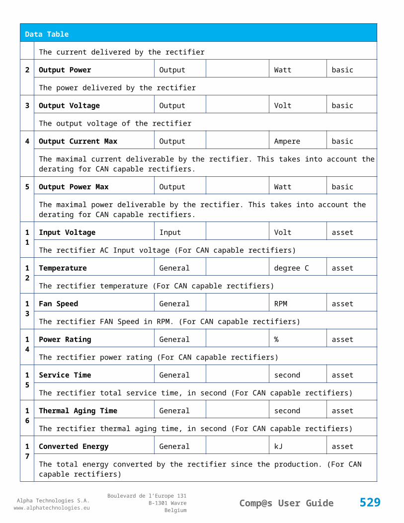
Alpha Technologies S.A.www.alphatechnologies.eu
Alpha Technologies S.A.www.alphatechnologies.eu
Comp@s User GuideBoulevard de l’Europe 131
B-1301 WavreBelgium
Config Table
Relay 3 Normal State
307
Relay 4 Change State Boolan Condition
Relays Relay 4 (False) basic
Relay 4 Boolean Condition
308
Relay 4 Normal State Relays Relay 4 (Energized / De-energized)
basic
Relay 4 Normal State
309
Relay 5 Change State Boolan Condition
Relays Relay 5 (False) basic
Relay 5 Boolean Condition
310
Relay 5 Normal State Relays Relay 5 (Energized / De-energized)
basic
Relay 5 Normal State
311
Relay 6 Change State Boolan Condition
Relays Relay 6 (False) basic
Relay 6 Boolean Condition
312
Relay 6 Normal State Relays Relay 6 (Energized / De-energized)
basic
Relay 6 Normal State
313
Relay 7 Change State Boolan Condition
Relays Relay 7 (False) basic
Relay 7 Boolean Condition
314
Relay 7 Normal State Relays Relay 7 (Energized / De-energized)
basic
Relay 7 Normal State
315
Relay 8 Change State Boolan Condition
Relays Relay 8 (False) basic
Relay 8 Boolean Condition
316
Relay 8 Normal State Relays Relay 8 (Energized / De-energized)
basic
Relay 8 Normal State
521
Read Access User Numbers
Generic Allowed Users (1,2,3,4,5) basic
529

Alpha Technologies S.A.www.alphatechnologies.eu
Alpha Technologies S.A.www.alphatechnologies.eu
Comp@s User GuideBoulevard de l’Europe 131
B-1301 WavreBelgium
Config Table
The list of the user numbers which have read access to this equipment. The user numbers are coma separated. The accepted user id are 1,2,3,4 and 5. Ex: 1,3,4
522
Write Access User Numbers
Generic Allowed Users () basic
The list of the user numbers which have write access to this equipment. This means that these users can modify the configuration element, the alarm settings and use the control elements. The user numbers are coma separated. The accepted user ids are 1,2,3,4 and 5. Ex: 1,3,4
601
Event Table Length Generic Events 10/4000 (100) basic
The maximum length of the table. The value must be comprised between 10 and 4000
901
Number Of PLC Data PLC (0) plc
The number of PLC data. Every equipment can manage up to 20 user programmable data. Data elements are automatically added in the data table. Configuration parameters are added to set the PLC Data Name and the PLC Data Mathematical calculation. In order to use these functionalities, you need a license with the 'PLC' module
902
Number Of PLC Alarm PLC (0) plc
The number of PLC alarm. Every equipment can manage up to 20 user programmable alarms. Alarm elements are automatically added in the alarm table. The alarm parameters are added to set the PLC Alarm Name and the PLC Alarm Boolean condition. In order to use these functionalities, you need a licence with the 'PLC' module
Control Table
Id Name Group SubGroup License
301
Invert Relay 1 State For X Seconds Relays Relay 1 basic
Generate Pulse on relay
303
Invert Relay 2 State For X Seconds Relays Relay 2 basic
Generate Pulse on relay
305
Invert Relay 3 State For X Seconds Relays Relay 3 basic
Generate Pulse on relay
307
Invert Relay 4 State For X Seconds Relays Relay 4 basic
Generate Pulse on relay
309
Invert Relay 5 State For X Seconds Relays Relay 5 basic
Generate Pulse on relay
530

Alpha Technologies S.A.www.alphatechnologies.eu
Alpha Technologies S.A.www.alphatechnologies.eu
Comp@s User GuideBoulevard de l’Europe 131
B-1301 WavreBelgium
Control Table
311
Invert Relay 6 State For X Seconds Relays Relay 6 basic
Generate Pulse on relay
313
Invert Relay 7 State For X Seconds Relays Relay 7 basic
Generate Pulse on relay
315
Invert Relay 8 State For X Seconds Relays Relay 8 basic
Generate Pulse on relay
501
Clear My Events Generic Events basic
By writing '1' to this control element, all the events of this equipment will be cleared.
502
Clear All Events Generic Events basic
By writing '1' to this control element, all the events of this equipment and all the events of all the sub-equipments will be cleared.
511
Add Event Generic Events basic
This control element adds an event of severity none. The event name is the text written to this control element
512
Add Major Event Generic Events basic
This control element adds an event of severity major. The event name is the text written to this control element
521
Reset Default Names And Groups Generic Renaming basic
This control element resets all the element Names, Groups and Subgroups to default values for this equipment
522
Reset Default Names And Groups Recursive Generic Renaming basic
This control element resets all the element Names, Groups and Subgroups to default values for this equipment and all sub equipments
7.4.9 ADIO SP0155/02
Device Information
Name ADIO SP0155/02
Short Description I/O module : 64 Dig Inputs
Long Description I/O module with Standard I/O module : 64 Dig Inputs
Hardware Reference 9413 001 55021
531

Alpha Technologies S.A.www.alphatechnologies.eu
Alpha Technologies S.A.www.alphatechnologies.eu
Comp@s User GuideBoulevard de l’Europe 131
B-1301 WavreBelgium
Device Information
Software Reference SOFT 000125 XX
Equipment Type System Extension
ETSI Level /site/sensors_and_actuators
Description Table
Id Name Group SubGroup License
1 Product Name Description Product Info basic
The commercial name of the extension card.
2 Hardware Reference Description Product Info basic
The hardware refence
3 Hardware Revision Description Product Info basic
The hardware revision
4 Software Reference Description Product Info basic
The software reference
6 Serial Number Description Product Info basic
The serial number.
8 Manufacturing Date Description Product Info basic
The production date.
11 Description Description Custom Description basic
A free text zone to write a system description
12 Reference Description Custom Description basic
A free text zone to write the customer reference of the system
Alarm Table
Id Name Group SubGroup Severity Type (Level) Set/Clear Delay
101 Digital Input 1 Digital Inputs Digital Input 1 warning (0) 5 / 2
The name of the digital input 1 alarm.
102 Digital Input 2 Digital Inputs Digital Input 2 warning (0) 5 / 2
532

Alpha Technologies S.A.www.alphatechnologies.eu
Alpha Technologies S.A.www.alphatechnologies.eu
Comp@s User GuideBoulevard de l’Europe 131
B-1301 WavreBelgium
Alarm Table
The name of the digital input 2 alarm.
103 Digital Input 3 Digital Inputs Digital Input 3 warning (0) 5 / 2
The name of the digital input 3 alarm.
104 Digital Input 4 Digital Inputs Digital Input 4 warning (0) 5 / 2
The name of the digital input 4 alarm.
105 Digital Input 5 Digital Inputs Digital Input 5 warning (0) 5 / 2
The name of the digital input 5 alarm.
106 Digital Input 6 Digital Inputs Digital Input 6 warning (0) 5 / 2
The name of the digital input 6 alarm.
107 Digital Input 7 Digital Inputs Digital Input 7 warning (0) 5 / 2
The name of the digital input 7 alarm.
108 Digital Input 8 Digital Inputs Digital Input 8 warning (0) 5 / 2
The name of the digital input 8 alarm.
109 Digital Input 9 Digital Inputs Digital Input 9 warning (0) 5 / 2
The name of the digital input 9 alarm.
110 Digital Input 10 Digital Inputs Digital Input 10 warning (0) 5 / 2
The name of the digital input 10 alarm.
111 Digital Input 11 Digital Inputs Digital Input 11 warning (0) 5 / 2
The name of the digital input 11 alarm.
112 Digital Input 12 Digital Inputs Digital Input 12 warning (0) 5 / 2
The name of the digital input 12 alarm.
113 Digital Input 13 Digital Inputs Digital Input 13 warning (0) 5 / 2
The name of the digital input 13 alarm.
114 Digital Input 14 Digital Inputs Digital Input 14 warning (0) 5 / 2
The name of the digital input 14 alarm.
115 Digital Input 15 Digital Inputs Digital Input 15 warning (0) 5 / 2
The name of the digital input 15 alarm.
533

Alpha Technologies S.A.www.alphatechnologies.eu
Alpha Technologies S.A.www.alphatechnologies.eu
Comp@s User GuideBoulevard de l’Europe 131
B-1301 WavreBelgium
Alarm Table
116 Digital Input 16 Digital Inputs Digital Input 16 warning (0) 5 / 2
The name of the digital input 16 alarm.
117 Digital Input 17 Digital Inputs Digital Input 17 warning (0) 5 / 2
The name of the digital input 17 alarm.
118 Digital Input 18 Digital Inputs Digital Input 18 warning (0) 5 / 2
The name of the digital input 18 alarm.
119 Digital Input 19 Digital Inputs Digital Input 19 warning (0) 5 / 2
The name of the digital input 19 alarm.
120 Digital Input 20 Digital Inputs Digital Input 20 warning (0) 5 / 2
The name of the digital input 20 alarm.
121 Digital Input 21 Digital Inputs Digital Input 21 warning (0) 5 / 2
The name of the digital input 21 alarm.
122 Digital Input 22 Digital Inputs Digital Input 22 warning (0) 5 / 2
The name of the digital input 22 alarm.
123 Digital Input 23 Digital Inputs Digital Input 23 warning (0) 5 / 2
The name of the digital input 23 alarm.
124 Digital Input 24 Digital Inputs Digital Input 24 warning (0) 5 / 2
The name of the digital input 24 alarm.
125 Digital Input 25 Digital Inputs Digital Input 25 warning (0) 5 / 2
The name of the digital input 25 alarm.
126 Digital Input 26 Digital Inputs Digital Input 26 warning (0) 5 / 2
The name of the digital input 26 alarm.
127 Digital Input 27 Digital Inputs Digital Input 27 warning (0) 5 / 2
The name of the digital input 27 alarm.
128 Digital Input 28 Digital Inputs Digital Input 28 warning (0) 5 / 2
The name of the digital input 28 alarm.
129 Digital Input 29 Digital Inputs Digital Input 29 warning (0) 5 / 2
534

Alpha Technologies S.A.www.alphatechnologies.eu
Alpha Technologies S.A.www.alphatechnologies.eu
Comp@s User GuideBoulevard de l’Europe 131
B-1301 WavreBelgium
Alarm Table
The name of the digital input 29 alarm.
130 Digital Input 30 Digital Inputs Digital Input 30 warning (0) 5 / 2
The name of the digital input 30 alarm.
131 Digital Input 31 Digital Inputs Digital Input 31 warning (0) 5 / 2
The name of the digital input 31 alarm.
132 Digital Input 32 Digital Inputs Digital Input 32 warning (0) 5 / 2
The name of the digital input 32 alarm.
133 Digital Input 33 Digital Inputs Digital Input 33 warning (0) 5 / 2
The name of the digital input 33 alarm.
134 Digital Input 34 Digital Inputs Digital Input 34 warning (0) 5 / 2
The name of the digital input 34 alarm.
135 Digital Input 35 Digital Inputs Digital Input 35 warning (0) 5 / 2
The name of the digital input 35 alarm.
136 Digital Input 36 Digital Inputs Digital Input 36 warning (0) 5 / 2
The name of the digital input 36 alarm.
137 Digital Input 37 Digital Inputs Digital Input 37 warning (0) 5 / 2
The name of the digital input 37 alarm.
138 Digital Input 38 Digital Inputs Digital Input 38 warning (0) 5 / 2
The name of the digital input 38 alarm.
139 Digital Input 39 Digital Inputs Digital Input 39 warning (0) 5 / 2
The name of the digital input 39 alarm.
140 Digital Input 40 Digital Inputs Digital Input 40 warning (0) 5 / 2
The name of the digital input 40 alarm.
141 Digital Input 41 Digital Inputs Digital Input 41 warning (0) 5 / 2
The name of the digital input 41 alarm.
142 Digital Input 42 Digital Inputs Digital Input 42 warning (0) 5 / 2
The name of the digital input 42 alarm.
535
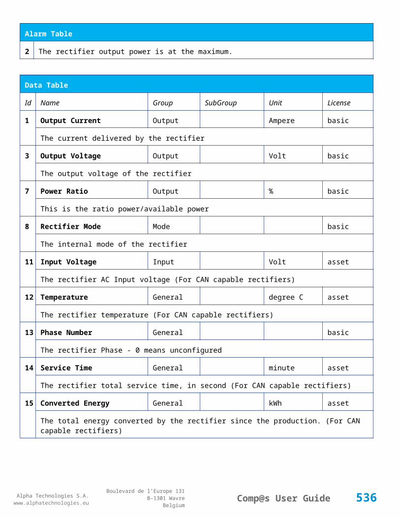
Alpha Technologies S.A.www.alphatechnologies.eu
Alpha Technologies S.A.www.alphatechnologies.eu
Comp@s User GuideBoulevard de l’Europe 131
B-1301 WavreBelgium
Alarm Table
143 Digital Input 43 Digital Inputs Digital Input 43 warning (0) 5 / 2
The name of the digital input 43 alarm.
144 Digital Input 44 Digital Inputs Digital Input 44 warning (0) 5 / 2
The name of the digital input 44 alarm.
145 Digital Input 45 Digital Inputs Digital Input 45 warning (0) 5 / 2
The name of the digital input 45 alarm.
146 Digital Input 46 Digital Inputs Digital Input 46 warning (0) 5 / 2
The name of the digital input 46 alarm.
147 Digital Input 47 Digital Inputs Digital Input 47 warning (0) 5 / 2
The name of the digital input 47 alarm.
148 Digital Input 48 Digital Inputs Digital Input 48 warning (0) 5 / 2
The name of the digital input 48 alarm.
149 Digital Input 49 Digital Inputs Digital Input 49 warning (0) 5 / 2
The name of the digital input 49 alarm.
150 Digital Input 50 Digital Inputs Digital Input 50 warning (0) 5 / 2
The name of the digital input 50 alarm.
151 Digital Input 51 Digital Inputs Digital Input 51 warning (0) 5 / 2
The name of the digital input 51 alarm.
152 Digital Input 52 Digital Inputs Digital Input 52 warning (0) 5 / 2
The name of the digital input 52 alarm.
153 Digital Input 53 Digital Inputs Digital Input 53 warning (0) 5 / 2
The name of the digital input 53 alarm.
154 Digital Input 54 Digital Inputs Digital Input 54 warning (0) 5 / 2
The name of the digital input 54 alarm.
155 Digital Input 55 Digital Inputs Digital Input 55 warning (0) 5 / 2
The name of the digital input 55 alarm.
156 Digital Input 56 Digital Inputs Digital Input 56 warning (0) 5 / 2
536

Alpha Technologies S.A.www.alphatechnologies.eu
Alpha Technologies S.A.www.alphatechnologies.eu
Comp@s User GuideBoulevard de l’Europe 131
B-1301 WavreBelgium
Alarm Table
The name of the digital input 56 alarm.
157 Digital Input 57 Digital Inputs Digital Input 57 warning (0) 5 / 2
The name of the digital input 57 alarm.
158 Digital Input 58 Digital Inputs Digital Input 58 warning (0) 5 / 2
The name of the digital input 58 alarm.
159 Digital Input 59 Digital Inputs Digital Input 59 warning (0) 5 / 2
The name of the digital input 59 alarm.
160 Digital Input 60 Digital Inputs Digital Input 60 warning (0) 5 / 2
The name of the digital input 60 alarm.
161 Digital Input 61 Digital Inputs Digital Input 61 warning (0) 5 / 2
The name of the digital input 61 alarm.
162 Digital Input 62 Digital Inputs Digital Input 62 warning (0) 5 / 2
The name of the digital input 62 alarm.
163 Digital Input 63 Digital Inputs Digital Input 63 warning (0) 5 / 2
The name of the digital input 63 alarm.
164 Digital Input 64 Digital Inputs Digital Input 64 warning (0) 5 / 2
The name of the digital input 64 alarm.
Data Table
Id Name Group SubGroup Unit License
101 Digital Input 1 State Digital Inputs Digital Input 1 basic
The state of the digital input
102 Digital Input 2 State Digital Inputs Digital Input 2 basic
The state of the digital input
103 Digital Input 3 State Digital Inputs Digital Input 3 basic
The state of the digital input
104 Digital Input 4 State Digital Inputs Digital Input 4 basic
537

Alpha Technologies S.A.www.alphatechnologies.eu
Alpha Technologies S.A.www.alphatechnologies.eu
Comp@s User GuideBoulevard de l’Europe 131
B-1301 WavreBelgium
Data Table
The state of the digital input
105 Digital Input 5 State Digital Inputs Digital Input 5 basic
The state of the digital input
106 Digital Input 6 State Digital Inputs Digital Input 6 basic
The state of the digital input
107 Digital Input 7 State Digital Inputs Digital Input 7 basic
The state of the digital input
108 Digital Input 8 State Digital Inputs Digital Input 8 basic
The state of the digital input
109 Digital Input 9 State Digital Inputs Digital Input 9 basic
The state of the digital input
110 Digital Input 10 State Digital Inputs Digital Input 10 basic
The state of the digital input
111 Digital Input 11 State Digital Inputs Digital Input 11 basic
The state of the digital input
112 Digital Input 12 State Digital Inputs Digital Input 12 basic
The state of the digital input
113 Digital Input 13 State Digital Inputs Digital Input 13 basic
The state of the digital input
114 Digital Input 14 State Digital Inputs Digital Input 14 basic
The state of the digital input
115 Digital Input 15 State Digital Inputs Digital Input 15 basic
The state of the digital input
116 Digital Input 16 State Digital Inputs Digital Input 16 basic
The state of the digital input
117 Digital Input 17 State Digital Inputs Digital Input 17 basic
The state of the digital input
538
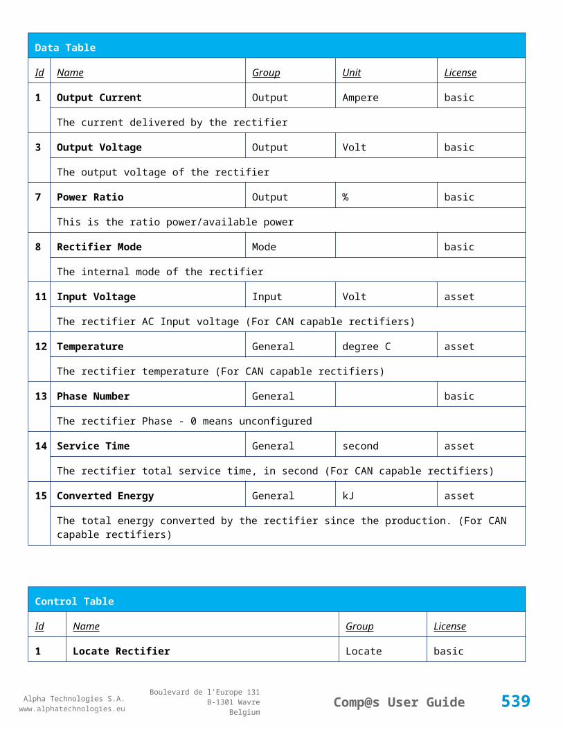
Alpha Technologies S.A.www.alphatechnologies.eu
Alpha Technologies S.A.www.alphatechnologies.eu
Comp@s User GuideBoulevard de l’Europe 131
B-1301 WavreBelgium
Data Table
118 Digital Input 18 State Digital Inputs Digital Input 18 basic
The state of the digital input
119 Digital Input 19 State Digital Inputs Digital Input 19 basic
The state of the digital input
120 Digital Input 20 State Digital Inputs Digital Input 20 basic
The state of the digital input
121 Digital Input 21 State Digital Inputs Digital Input 21 basic
The state of the digital input
122 Digital Input 22 State Digital Inputs Digital Input 22 basic
The state of the digital input
123 Digital Input 23 State Digital Inputs Digital Input 23 basic
The state of the digital input
124 Digital Input 24 State Digital Inputs Digital Input 24 basic
The state of the digital input
125 Digital Input 25 State Digital Inputs Digital Input 25 basic
The state of the digital input
126 Digital Input 26 State Digital Inputs Digital Input 26 basic
The state of the digital input
127 Digital Input 27 State Digital Inputs Digital Input 27 basic
The state of the digital input
128 Digital Input 28 State Digital Inputs Digital Input 28 basic
The state of the digital input
129 Digital Input 29 State Digital Inputs Digital Input 29 basic
The state of the digital input
130 Digital Input 30 State Digital Inputs Digital Input 30 basic
The state of the digital input
131 Digital Input 31 State Digital Inputs Digital Input 31 basic
539

Alpha Technologies S.A.www.alphatechnologies.eu
Alpha Technologies S.A.www.alphatechnologies.eu
Comp@s User GuideBoulevard de l’Europe 131
B-1301 WavreBelgium
Data Table
The state of the digital input
132 Digital Input 32 State Digital Inputs Digital Input 32 basic
The state of the digital input
133 Digital Input 33 State Digital Inputs Digital Input 33 basic
The state of the digital input
134 Digital Input 34 State Digital Inputs Digital Input 34 basic
The state of the digital input
135 Digital Input 35 State Digital Inputs Digital Input 35 basic
The state of the digital input
136 Digital Input 36 State Digital Inputs Digital Input 36 basic
The state of the digital input
137 Digital Input 37 State Digital Inputs Digital Input 37 basic
The state of the digital input
138 Digital Input 38 State Digital Inputs Digital Input 38 basic
The state of the digital input
139 Digital Input 39 State Digital Inputs Digital Input 39 basic
The state of the digital input
140 Digital Input 40 State Digital Inputs Digital Input 40 basic
The state of the digital input
141 Digital Input 41 State Digital Inputs Digital Input 41 basic
The state of the digital input
142 Digital Input 42 State Digital Inputs Digital Input 42 basic
The state of the digital input
143 Digital Input 43 State Digital Inputs Digital Input 43 basic
The state of the digital input
144 Digital Input 44 State Digital Inputs Digital Input 44 basic
The state of the digital input
540

Alpha Technologies S.A.www.alphatechnologies.eu
Alpha Technologies S.A.www.alphatechnologies.eu
Comp@s User GuideBoulevard de l’Europe 131
B-1301 WavreBelgium
Data Table
145 Digital Input 45 State Digital Inputs Digital Input 45 basic
The state of the digital input
146 Digital Input 46 State Digital Inputs Digital Input 46 basic
The state of the digital input
147 Digital Input 47 State Digital Inputs Digital Input 47 basic
The state of the digital input
148 Digital Input 48 State Digital Inputs Digital Input 48 basic
The state of the digital input
149 Digital Input 49 State Digital Inputs Digital Input 49 basic
The state of the digital input
150 Digital Input 50 State Digital Inputs Digital Input 50 basic
The state of the digital input
151 Digital Input 51 State Digital Inputs Digital Input 51 basic
The state of the digital input
152 Digital Input 52 State Digital Inputs Digital Input 52 basic
The state of the digital input
153 Digital Input 53 State Digital Inputs Digital Input 53 basic
The state of the digital input
154 Digital Input 54 State Digital Inputs Digital Input 54 basic
The state of the digital input
155 Digital Input 55 State Digital Inputs Digital Input 55 basic
The state of the digital input
156 Digital Input 56 State Digital Inputs Digital Input 56 basic
The state of the digital input
157 Digital Input 57 State Digital Inputs Digital Input 57 basic
The state of the digital input
158 Digital Input 58 State Digital Inputs Digital Input 58 basic
541

Alpha Technologies S.A.www.alphatechnologies.eu
Alpha Technologies S.A.www.alphatechnologies.eu
Comp@s User GuideBoulevard de l’Europe 131
B-1301 WavreBelgium
Data Table
The state of the digital input
159 Digital Input 59 State Digital Inputs Digital Input 59 basic
The state of the digital input
160 Digital Input 60 State Digital Inputs Digital Input 60 basic
The state of the digital input
161 Digital Input 61 State Digital Inputs Digital Input 61 basic
The state of the digital input
162 Digital Input 62 State Digital Inputs Digital Input 62 basic
The state of the digital input
163 Digital Input 63 State Digital Inputs Digital Input 63 basic
The state of the digital input
164 Digital Input 64 State Digital Inputs Digital Input 64 basic
The state of the digital input
Config Table
Id Name Group SubGroup Unit Range: Min/Max (default)
License
102
Digital Input 1 Name Digital Inputs Digital Input 1 Digital Inputs basic
The name of the digital input 1.
103
Digital Input 1 Normally Closed
Digital Inputs Digital Input 1 True/False (True) basic
True/False value defining if the digital input 1 is normally closed. If this digital input is not in this default state, the related alarm is set.
104
Digital Input 2 Name Digital Inputs Digital Input 2 Digital Inputs basic
The name of the digital input 2.
105
Digital Input 2 Normally Closed
Digital Inputs Digital Input 2 True/False (True) basic
True/False value defining if the digital input 2 is normally closed. If this digital input is not in this default state, the related alarm is set.
10 Digital Input 3 Name Digital Inputs Digital Input 3 Digital Inputs basic
542

Alpha Technologies S.A.www.alphatechnologies.eu
Alpha Technologies S.A.www.alphatechnologies.eu
Comp@s User GuideBoulevard de l’Europe 131
B-1301 WavreBelgium
Config Table
6 The name of the digital input 3.
107
Digital Input 3 Normally Closed
Digital Inputs Digital Input 3 True/False (True) basic
True/False value defining if the digital input 3 is normally closed. If this digital input is not in this default state, the related alarm is set.
108
Digital Input 4 Name Digital Inputs Digital Input 4 Digital Inputs basic
The name of the digital input 4.
109
Digital Input 4 Normally Closed
Digital Inputs Digital Input 4 True/False (True) basic
True/False value defining if the digital input 4 is normally closed. If this digital input is not in this default state, the related alarm is set.
110
Digital Input 5 Name Digital Inputs Digital Input 5 Digital Inputs basic
The name of the digital input 5.
111
Digital Input 5 Normally Closed
Digital Inputs Digital Input 5 True/False (True) basic
True/False value defining if the digital input 5 is normally closed. If this digital input is not in this default state, the related alarm is set.
112
Digital Input 6 Name Digital Inputs Digital Input 6 Digital Inputs basic
The name of the digital input 6.
113
Digital Input 6 Normally Closed
Digital Inputs Digital Input 6 True/False (True) basic
True/False value defining if the digital input 6 is normally closed. If this digital input is not in this default state, the related alarm is set.
114
Digital Input 7 Name Digital Inputs Digital Input 7 Digital Inputs basic
The name of the digital input 7.
115
Digital Input 7 Normally Closed
Digital Inputs Digital Input 7 True/False (True) basic
True/False value defining if the digital input 7 is normally closed. If this digital input is not in this default state, the related alarm is set.
116
Digital Input 8 Name Digital Inputs Digital Input 8 Digital Inputs basic
The name of the digital input 8.
117
Digital Input 8 Normally Closed
Digital Inputs Digital Input 8 True/False (True) basic
543
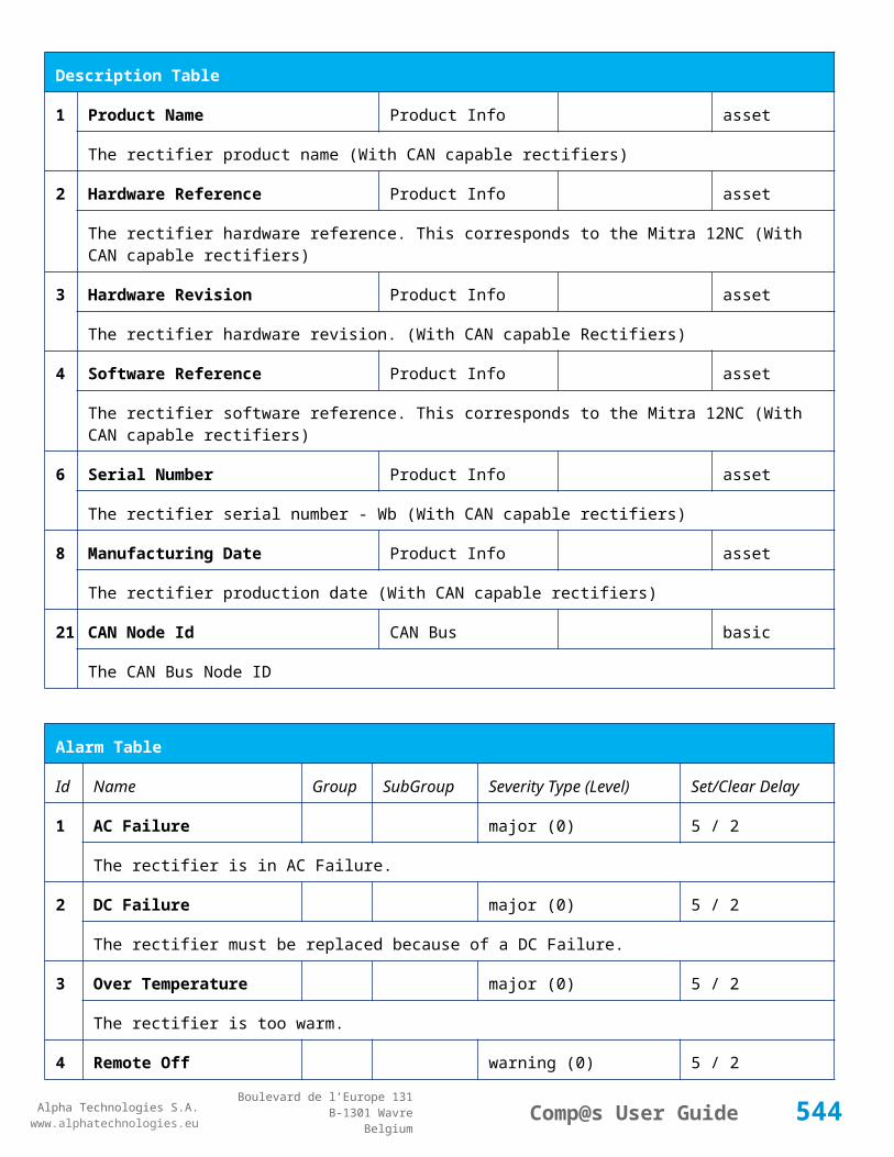
Alpha Technologies S.A.www.alphatechnologies.eu
Alpha Technologies S.A.www.alphatechnologies.eu
Comp@s User GuideBoulevard de l’Europe 131
B-1301 WavreBelgium
Config Table
True/False value defining if the digital input 8 is normally closed. If this digital input is not in this default state, the related alarm is set.
118
Digital Input 9 Name Digital Inputs Digital Input 9 Digital Inputs basic
The name of the digital input 9.
119
Digital Input 9 Normally Closed
Digital Inputs Digital Input 9 True/False (True) basic
True/False value defining if the digital input 9 is normally closed. If this digital input is not in this default state, the related alarm is set.
120
Digital Input 10 Name Digital Inputs Digital Input 10 Digital Inputs basic
The name of the digital input 10.
121
Digital Input 10 Normally Closed
Digital Inputs Digital Input 10 True/False (True) basic
True/False value defining if the digital input 10 is normally closed. If this digital input is not in this default state, the related alarm is set.
122
Digital Input 11 Name Digital Inputs Digital Input 11 Digital Inputs basic
The name of the digital input 11.
123
Digital Input 11 Normally Closed
Digital Inputs Digital Input 11 True/False (True) basic
True/False value defining if the digital input 11 is normally closed. If this digital input is not in this default state, the related alarm is set.
124
Digital Input 12 Name Digital Inputs Digital Input 12 Digital Inputs basic
The name of the digital input 12.
125
Digital Input 12 Normally Closed
Digital Inputs Digital Input 12 True/False (True) basic
True/False value defining if the digital input 12 is normally closed. If this digital input is not in this default state, the related alarm is set.
126
Digital Input 13 Name Digital Inputs Digital Input 13 Digital Inputs basic
The name of the digital input 13.
127
Digital Input 13 Normally Closed
Digital Inputs Digital Input 13 True/False (True) basic
True/False value defining if the digital input 13 is normally closed. If this digital input is not in this default state, the related alarm is set.
12 Digital Input 14 Name Digital Inputs Digital Input 14 Digital Inputs basic
544

Alpha Technologies S.A.www.alphatechnologies.eu
Alpha Technologies S.A.www.alphatechnologies.eu
Comp@s User GuideBoulevard de l’Europe 131
B-1301 WavreBelgium
Config Table
8 The name of the digital input 14.
129
Digital Input 14 Normally Closed
Digital Inputs Digital Input 14 True/False (True) basic
True/False value defining if the digital input 14 is normally closed. If this digital input is not in this default state, the related alarm is set.
130
Digital Input 15 Name Digital Inputs Digital Input 15 Digital Inputs basic
The name of the digital input 15.
131
Digital Input 15 Normally Closed
Digital Inputs Digital Input 15 True/False (True) basic
True/False value defining if the digital input 15 is normally closed. If this digital input is not in this default state, the related alarm is set.
132
Digital Input 16 Name Digital Inputs Digital Input 16 Digital Inputs basic
The name of the digital input 16.
133
Digital Input 16 Normally Closed
Digital Inputs Digital Input 16 True/False (True) basic
True/False value defining if the digital input 16 is normally closed. If this digital input is not in this default state, the related alarm is set.
134
Digital Input 17 Name Digital Inputs Digital Input 17 Digital Inputs basic
The name of the digital input 17.
135
Digital Input 17 Normally Closed
Digital Inputs Digital Input 17 True/False (True) basic
True/False value defining if the digital input 17 is normally closed. If this digital input is not in this default state, the related alarm is set.
136
Digital Input 18 Name Digital Inputs Digital Input 18 Digital Inputs basic
The name of the digital input 18.
137
Digital Input 18 Normally Closed
Digital Inputs Digital Input 18 True/False (True) basic
True/False value defining if the digital input 18 is normally closed. If this digital input is not in this default state, the related alarm is set.
138
Digital Input 19 Name Digital Inputs Digital Input 19 Digital Inputs basic
The name of the digital input 19.
139
Digital Input 19 Normally Closed
Digital Inputs Digital Input 19 True/False (True) basic
545

Alpha Technologies S.A.www.alphatechnologies.eu
Alpha Technologies S.A.www.alphatechnologies.eu
Comp@s User GuideBoulevard de l’Europe 131
B-1301 WavreBelgium
Config Table
True/False value defining if the digital input 19 is normally closed. If this digital input is not in this default state, the related alarm is set.
140
Digital Input 20 Name Digital Inputs Digital Input 20 Digital Inputs basic
The name of the digital input 20.
141
Digital Input 20 Normally Closed
Digital Inputs Digital Input 20 True/False (True) basic
True/False value defining if the digital input 20 is normally closed. If this digital input is not in this default state, the related alarm is set.
142
Digital Input 21 Name Digital Inputs Digital Input 21 Digital Inputs basic
The name of the digital input 21.
143
Digital Input 21 Normally Closed
Digital Inputs Digital Input 21 True/False (True) basic
True/False value defining if the digital input 21 is normally closed. If this digital input is not in this default state, the related alarm is set.
144
Digital Input 22 Name Digital Inputs Digital Input 22 Digital Inputs basic
The name of the digital input 22.
145
Digital Input 22 Normally Closed
Digital Inputs Digital Input 22 True/False (True) basic
True/False value defining if the digital input 22 is normally closed. If this digital input is not in this default state, the related alarm is set.
146
Digital Input 23 Name Digital Inputs Digital Input 23 Digital Inputs basic
The name of the digital input 23.
147
Digital Input 23 Normally Closed
Digital Inputs Digital Input 23 True/False (True) basic
True/False value defining if the digital input 23 is normally closed. If this digital input is not in this default state, the related alarm is set.
148
Digital Input 24 Name Digital Inputs Digital Input 24 Digital Inputs basic
The name of the digital input 24.
149
Digital Input 24 Normally Closed
Digital Inputs Digital Input 24 True/False (True) basic
True/False value defining if the digital input 24 is normally closed. If this digital input is not in this default state, the related alarm is set.
15 Digital Input 25 Name Digital Inputs Digital Input 25 Digital Inputs basic
546

Alpha Technologies S.A.www.alphatechnologies.eu
Alpha Technologies S.A.www.alphatechnologies.eu
Comp@s User GuideBoulevard de l’Europe 131
B-1301 WavreBelgium
Config Table
0 The name of the digital input 25.
151
Digital Input 25 Normally Closed
Digital Inputs Digital Input 25 True/False (True) basic
True/False value defining if the digital input 25 is normally closed. If this digital input is not in this default state, the related alarm is set.
152
Digital Input 26 Name Digital Inputs Digital Input 26 Digital Inputs basic
The name of the digital input 26.
153
Digital Input 26 Normally Closed
Digital Inputs Digital Input 26 True/False (True) basic
True/False value defining if the digital input 26 is normally closed. If this digital input is not in this default state, the related alarm is set.
154
Digital Input 27 Name Digital Inputs Digital Input 27 Digital Inputs basic
The name of the digital input 27.
155
Digital Input 27 Normally Closed
Digital Inputs Digital Input 27 True/False (True) basic
True/False value defining if the digital input 27 is normally closed. If this digital input is not in this default state, the related alarm is set.
156
Digital Input 28 Name Digital Inputs Digital Input 28 Digital Inputs basic
The name of the digital input 28.
157
Digital Input 28 Normally Closed
Digital Inputs Digital Input 28 True/False (True) basic
True/False value defining if the digital input 28 is normally closed. If this digital input is not in this default state, the related alarm is set.
158
Digital Input 29 Name Digital Inputs Digital Input 29 Digital Inputs basic
The name of the digital input 29.
159
Digital Input 29 Normally Closed
Digital Inputs Digital Input 29 True/False (True) basic
True/False value defining if the digital input 29 is normally closed. If this digital input is not in this default state, the related alarm is set.
160
Digital Input 30 Name Digital Inputs Digital Input 30 Digital Inputs basic
The name of the digital input 30.
161
Digital Input 30 Normally Closed
Digital Inputs Digital Input 30 True/False (True) basic
547

Alpha Technologies S.A.www.alphatechnologies.eu
Alpha Technologies S.A.www.alphatechnologies.eu
Comp@s User GuideBoulevard de l’Europe 131
B-1301 WavreBelgium
Config Table
True/False value defining if the digital input 30 is normally closed. If this digital input is not in this default state, the related alarm is set.
162
Digital Input 31 Name Digital Inputs Digital Input 31 Digital Inputs basic
The name of the digital input 31.
163
Digital Input 31 Normally Closed
Digital Inputs Digital Input 31 True/False (True) basic
True/False value defining if the digital input 31 is normally closed. If this digital input is not in this default state, the related alarm is set.
164
Digital Input 32 Name Digital Inputs Digital Input 32 Digital Inputs basic
The name of the digital input 32.
165
Digital Input 32 Normally Closed
Digital Inputs Digital Input 32 True/False (True) basic
True/False value defining if the digital input 32 is normally closed. If this digital input is not in this default state, the related alarm is set.
166
Digital Input 33 Name Digital Inputs Digital Input 33 Digital Inputs basic
The name of the digital input 33.
167
Digital Input 33 Normally Closed
Digital Inputs Digital Input 33 True/False (True) basic
True/False value defining if the digital input 33 is normally closed. If this digital input is not in this default state, the related alarm is set.
168
Digital Input 34 Name Digital Inputs Digital Input 34 Digital Inputs basic
The name of the digital input 34.
169
Digital Input 34 Normally Closed
Digital Inputs Digital Input 34 True/False (True) basic
True/False value defining if the digital input 34 is normally closed. If this digital input is not in this default state, the related alarm is set.
170
Digital Input 35 Name Digital Inputs Digital Input 35 Digital Inputs basic
The name of the digital input 35.
171
Digital Input 35 Normally Closed
Digital Inputs Digital Input 35 True/False (True) basic
True/False value defining if the digital input 35 is normally closed. If this digital input is not in this default state, the related alarm is set.
17 Digital Input 36 Name Digital Inputs Digital Input 36 Digital Inputs basic
548

Alpha Technologies S.A.www.alphatechnologies.eu
Alpha Technologies S.A.www.alphatechnologies.eu
Comp@s User GuideBoulevard de l’Europe 131
B-1301 WavreBelgium
Config Table
2 The name of the digital input 36.
173
Digital Input 36 Normally Closed
Digital Inputs Digital Input 36 True/False (True) basic
True/False value defining if the digital input 36 is normally closed. If this digital input is not in this default state, the related alarm is set.
174
Digital Input 37 Name Digital Inputs Digital Input 37 Digital Inputs basic
The name of the digital input 37.
175
Digital Input 37 Normally Closed
Digital Inputs Digital Input 37 True/False (True) basic
True/False value defining if the digital input 37 is normally closed. If this digital input is not in this default state, the related alarm is set.
176
Digital Input 38 Name Digital Inputs Digital Input 38 Digital Inputs basic
The name of the digital input 38.
177
Digital Input 38 Normally Closed
Digital Inputs Digital Input 38 True/False (True) basic
True/False value defining if the digital input 38 is normally closed. If this digital input is not in this default state, the related alarm is set.
178
Digital Input 39 Name Digital Inputs Digital Input 39 Digital Inputs basic
The name of the digital input 39.
179
Digital Input 39 Normally Closed
Digital Inputs Digital Input 39 True/False (True) basic
True/False value defining if the digital input 39 is normally closed. If this digital input is not in this default state, the related alarm is set.
180
Digital Input 40 Name Digital Inputs Digital Input 40 Digital Inputs basic
The name of the digital input 40.
181
Digital Input 40 Normally Closed
Digital Inputs Digital Input 40 True/False (True) basic
True/False value defining if the digital input 40 is normally closed. If this digital input is not in this default state, the related alarm is set.
182
Digital Input 41 Name Digital Inputs Digital Input 41 Digital Inputs basic
The name of the digital input 41.
183
Digital Input 41 Normally Closed
Digital Inputs Digital Input 41 True/False (True) basic
549
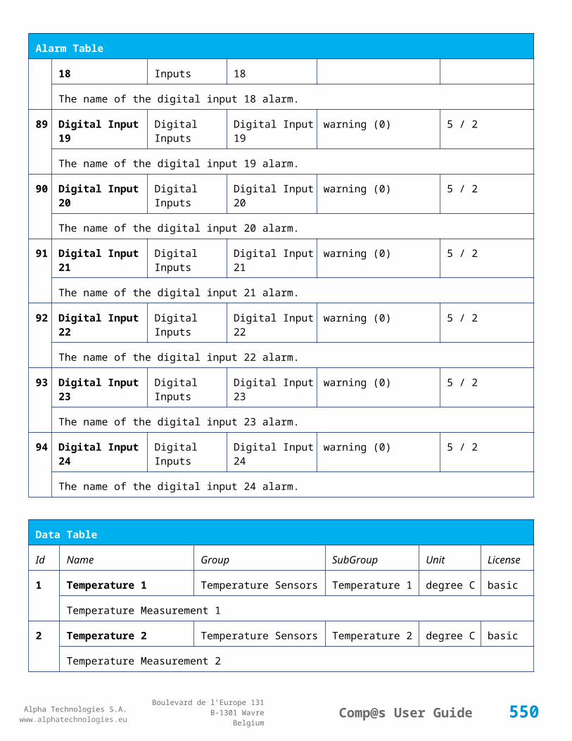
Alpha Technologies S.A.www.alphatechnologies.eu
Alpha Technologies S.A.www.alphatechnologies.eu
Comp@s User GuideBoulevard de l’Europe 131
B-1301 WavreBelgium
Config Table
True/False value defining if the digital input 41 is normally closed. If this digital input is not in this default state, the related alarm is set.
184
Digital Input 42 Name Digital Inputs Digital Input 42 Digital Inputs basic
The name of the digital input 42.
185
Digital Input 42 Normally Closed
Digital Inputs Digital Input 42 True/False (True) basic
True/False value defining if the digital input 42 is normally closed. If this digital input is not in this default state, the related alarm is set.
186
Digital Input 43 Name Digital Inputs Digital Input 43 Digital Inputs basic
The name of the digital input 43.
187
Digital Input 43 Normally Closed
Digital Inputs Digital Input 43 True/False (True) basic
True/False value defining if the digital input 43 is normally closed. If this digital input is not in this default state, the related alarm is set.
188
Digital Input 44 Name Digital Inputs Digital Input 44 Digital Inputs basic
The name of the digital input 44.
189
Digital Input 44 Normally Closed
Digital Inputs Digital Input 44 True/False (True) basic
True/False value defining if the digital input 44 is normally closed. If this digital input is not in this default state, the related alarm is set.
190
Digital Input 45 Name Digital Inputs Digital Input 45 Digital Inputs basic
The name of the digital input 45.
191
Digital Input 45 Normally Closed
Digital Inputs Digital Input 45 True/False (True) basic
True/False value defining if the digital input 45 is normally closed. If this digital input is not in this default state, the related alarm is set.
192
Digital Input 46 Name Digital Inputs Digital Input 46 Digital Inputs basic
The name of the digital input 46.
193
Digital Input 46 Normally Closed
Digital Inputs Digital Input 46 True/False (True) basic
True/False value defining if the digital input 46 is normally closed. If this digital input is not in this default state, the related alarm is set.
19 Digital Input 47 Name Digital Inputs Digital Input 47 Digital Inputs basic
550

Alpha Technologies S.A.www.alphatechnologies.eu
Alpha Technologies S.A.www.alphatechnologies.eu
Comp@s User GuideBoulevard de l’Europe 131
B-1301 WavreBelgium
Config Table
4 The name of the digital input 47.
195
Digital Input 47 Normally Closed
Digital Inputs Digital Input 47 True/False (True) basic
True/False value defining if the digital input 47 is normally closed. If this digital input is not in this default state, the related alarm is set.
196
Digital Input 48 Name Digital Inputs Digital Input 48 Digital Inputs basic
The name of the digital input 48.
197
Digital Input 48 Normally Closed
Digital Inputs Digital Input 48 True/False (True) basic
True/False value defining if the digital input 48 is normally closed. If this digital input is not in this default state, the related alarm is set.
198
Digital Input 49 Name Digital Inputs Digital Input 49 Digital Inputs basic
The name of the digital input 49.
199
Digital Input 49 Normally Closed
Digital Inputs Digital Input 49 True/False (True) basic
True/False value defining if the digital input 49 is normally closed. If this digital input is not in this default state, the related alarm is set.
200
Digital Input 50 Name Digital Inputs Digital Input 50 Digital Inputs basic
The name of the digital input 50.
201
Digital Input 50 Normally Closed
Digital Inputs Digital Input 50 True/False (True) basic
True/False value defining if the digital input 50 is normally closed. If this digital input is not in this default state, the related alarm is set.
202
Digital Input 51 Name Digital Inputs Digital Input 51 Digital Inputs basic
The name of the digital input 51.
203
Digital Input 51 Normally Closed
Digital Inputs Digital Input 51 True/False (True) basic
True/False value defining if the digital input 51 is normally closed. If this digital input is not in this default state, the related alarm is set.
204
Digital Input 52 Name Digital Inputs Digital Input 52 Digital Inputs basic
The name of the digital input 52.
205
Digital Input 52 Normally Closed
Digital Inputs Digital Input 52 True/False (True) basic
551

Alpha Technologies S.A.www.alphatechnologies.eu
Alpha Technologies S.A.www.alphatechnologies.eu
Comp@s User GuideBoulevard de l’Europe 131
B-1301 WavreBelgium
Config Table
True/False value defining if the digital input 52 is normally closed. If this digital input is not in this default state, the related alarm is set.
206
Digital Input 53 Name Digital Inputs Digital Input 53 Digital Inputs basic
The name of the digital input 53.
207
Digital Input 53 Normally Closed
Digital Inputs Digital Input 53 True/False (True) basic
True/False value defining if the digital input 53 is normally closed. If this digital input is not in this default state, the related alarm is set.
208
Digital Input 54 Name Digital Inputs Digital Input 54 Digital Inputs basic
The name of the digital input 54.
209
Digital Input 54 Normally Closed
Digital Inputs Digital Input 54 True/False (True) basic
True/False value defining if the digital input 54 is normally closed. If this digital input is not in this default state, the related alarm is set.
210
Digital Input 55 Name Digital Inputs Digital Input 55 Digital Inputs basic
The name of the digital input 55.
211
Digital Input 55 Normally Closed
Digital Inputs Digital Input 55 True/False (True) basic
True/False value defining if the digital input 55 is normally closed. If this digital input is not in this default state, the related alarm is set.
212
Digital Input 56 Name Digital Inputs Digital Input 56 Digital Inputs basic
The name of the digital input 56.
213
Digital Input 56 Normally Closed
Digital Inputs Digital Input 56 True/False (True) basic
True/False value defining if the digital input 56 is normally closed. If this digital input is not in this default state, the related alarm is set.
214
Digital Input 57 Name Digital Inputs Digital Input 57 Digital Inputs basic
The name of the digital input 57.
215
Digital Input 57 Normally Closed
Digital Inputs Digital Input 57 True/False (True) basic
True/False value defining if the digital input 57 is normally closed. If this digital input is not in this default state, the related alarm is set.
21 Digital Input 58 Name Digital Inputs Digital Input 58 Digital Inputs basic
552

Alpha Technologies S.A.www.alphatechnologies.eu
Alpha Technologies S.A.www.alphatechnologies.eu
Comp@s User GuideBoulevard de l’Europe 131
B-1301 WavreBelgium
Config Table
6 The name of the digital input 58.
217
Digital Input 58 Normally Closed
Digital Inputs Digital Input 58 True/False (True) basic
True/False value defining if the digital input 58 is normally closed. If this digital input is not in this default state, the related alarm is set.
218
Digital Input 59 Name Digital Inputs Digital Input 59 Digital Inputs basic
The name of the digital input 59.
219
Digital Input 59 Normally Closed
Digital Inputs Digital Input 59 True/False (True) basic
True/False value defining if the digital input 59 is normally closed. If this digital input is not in this default state, the related alarm is set.
220
Digital Input 60 Name Digital Inputs Digital Input 60 Digital Inputs basic
The name of the digital input 60.
221
Digital Input 60 Normally Closed
Digital Inputs Digital Input 60 True/False (True) basic
True/False value defining if the digital input 60 is normally closed. If this digital input is not in this default state, the related alarm is set.
222
Digital Input 61 Name Digital Inputs Digital Input 61 Digital Inputs basic
The name of the digital input 61.
223
Digital Input 61 Normally Closed
Digital Inputs Digital Input 61 True/False (True) basic
True/False value defining if the digital input 61 is normally closed. If this digital input is not in this default state, the related alarm is set.
224
Digital Input 62 Name Digital Inputs Digital Input 62 Digital Inputs basic
The name of the digital input 62.
225
Digital Input 62 Normally Closed
Digital Inputs Digital Input 62 True/False (True) basic
True/False value defining if the digital input 62 is normally closed. If this digital input is not in this default state, the related alarm is set.
226
Digital Input 63 Name Digital Inputs Digital Input 63 Digital Inputs basic
The name of the digital input 63.
227
Digital Input 63 Normally Closed
Digital Inputs Digital Input 63 True/False (True) basic
553

Alpha Technologies S.A.www.alphatechnologies.eu
Alpha Technologies S.A.www.alphatechnologies.eu
Comp@s User GuideBoulevard de l’Europe 131
B-1301 WavreBelgium
Config Table
True/False value defining if the digital input 63 is normally closed. If this digital input is not in this default state, the related alarm is set.
228
Digital Input 64 Name Digital Inputs Digital Input 64 Digital Inputs basic
The name of the digital input 64.
229
Digital Input 64 Normally Closed
Digital Inputs Digital Input 64 True/False (True) basic
True/False value defining if the digital input 64 is normally closed. If this digital input is not in this default state, the related alarm is set.
521
Read Access User Numbers
Generic Allowed Users (1,2,3,4,5) basic
The list of the user numbers which have read access to this equipment. The user numbers are coma separated. The accepted user id are 1,2,3,4 and 5. Ex: 1,3,4
522
Write Access User Numbers
Generic Allowed Users () basic
The list of the user numbers which have write access to this equipment. This means that these users can modify the configuration element, the alarm settings and use the control elements. The user numbers are coma separated. The accepted user ids are 1,2,3,4 and 5. Ex: 1,3,4
601
Event Table Length Generic Events 10/4000 (100) basic
The maximum length of the table. The value must be comprised between 10 and 4000
901
Number Of PLC Data PLC (0) plc
The number of PLC data. Every equipment can manage up to 20 user programmable data. Data elements are automatically added in the data table. Configuration parameters are added to set the PLC Data Name and the PLC Data Mathematical calculation. In order to use these functionalities, you need a license with the 'PLC' module
902
Number Of PLC Alarm PLC (0) plc
The number of PLC alarm. Every equipment can manage up to 20 user programmable alarms. Alarm elements are automatically added in the alarm table. The alarm parameters are added to set the PLC Alarm Name and the PLC Alarm Boolean condition. In order to use these functionalities, you need a licence with the 'PLC' module
Control Table
Id Name Group SubGroup License
501
Clear My Events Generic Events basic
By writing '1' to this control element, all the events of this equipment will be cleared.
554

Alpha Technologies S.A.www.alphatechnologies.eu
Alpha Technologies S.A.www.alphatechnologies.eu
Comp@s User GuideBoulevard de l’Europe 131
B-1301 WavreBelgium
Control Table
502
Clear All Events Generic Events basic
By writing '1' to this control element, all the events of this equipment and all the events of all the sub-equipments will be cleared.
511
Add Event Generic Events basic
This control element adds an event of severity none. The event name is the text written to this control element
512
Add Major Event Generic Events basic
This control element adds an event of severity major. The event name is the text written to this control element
521
Reset Default Names And Groups Generic Renaming basic
This control element resets all the element Names, Groups and Subgroups to default values for this equipment
522
Reset Default Names And Groups Recursive Generic Renaming basic
This control element resets all the element Names, Groups and Subgroups to default values for this equipment and all sub equipments
7.4.10 BIOM
Device Information
Name BIOM
Short Description COMP@S BASIC I/O MODULE SYS BIOM
Long Description 12 Digital Inputs, 4 output relay, 2 temperature sensors
Hardware Reference 9413 060 05051
Software Reference SOFT 000037 XX
Equipment Type System Extension
ETSI Level /site/sensors_and_actuators
Description Table
Id Name Group SubGroup License
1 Product Name Description Product Info basic
The commercial name of the extension card.
555

Alpha Technologies S.A.www.alphatechnologies.eu
Alpha Technologies S.A.www.alphatechnologies.eu
Comp@s User GuideBoulevard de l’Europe 131
B-1301 WavreBelgium
Description Table
2 Hardware Reference Description Product Info basic
The hardware refence
3 Hardware Revision Description Product Info basic
The hardware revision
4 Software Reference Description Product Info basic
The software reference
6 Serial Number Description Product Info basic
The serial number.
8 Manufacturing Date Description Product Info basic
The production date.
11 Description Description Custom Description basic
A free text zone to write a system description
12 Reference Description Custom Description basic
A free text zone to write the customer reference of the system
Alarm Table
Id Name Group SubGroup Severity Type (Level) Set/Clear Delay
71 Digital Input 1 Digital Inputs Digital Input 1 warning (0) 5 / 2
The name of the digital input 1 alarm.
72 Digital Input 2 Digital Inputs Digital Input 2 warning (0) 5 / 2
The name of the digital input 2 alarm.
73 Digital Input 3 Digital Inputs Digital Input 3 warning (0) 5 / 2
The name of the digital input 3 alarm.
74 Digital Input 4 Digital Inputs Digital Input 4 warning (0) 5 / 2
The name of the digital input 4 alarm.
75 Digital Input 5 Digital Inputs Digital Input 5 warning (0) 5 / 2
The name of the digital input 5 alarm.
556

Alpha Technologies S.A.www.alphatechnologies.eu
Alpha Technologies S.A.www.alphatechnologies.eu
Comp@s User GuideBoulevard de l’Europe 131
B-1301 WavreBelgium
Alarm Table
76 Digital Input 6 Digital Inputs Digital Input 6 warning (0) 5 / 2
The name of the digital input 6 alarm.
77 Digital Input 7 Digital Inputs Digital Input 7 warning (0) 5 / 2
The name of the digital input 7 alarm.
78 Digital Input 8 Digital Inputs Digital Input 8 warning (0) 5 / 2
The name of the digital input 8 alarm.
79 Digital Input 9 Digital Inputs Digital Input 9 warning (0) 5 / 2
The name of the digital input 9 alarm.
80 Digital Input 10 Digital Inputs Digital Input 10 warning (0) 5 / 2
The name of the digital input 10 alarm.
81 Digital Input 11 Digital Inputs Digital Input 11 warning (0) 5 / 2
The name of the digital input 11 alarm.
82 Digital Input 12 Digital Inputs Digital Input 12 warning (0) 5 / 2
The name of the digital input 12 alarm.
Data Table
Id Name Group SubGroup Unit License
1 Temperature 1 Temperature Sensors Temperature 1 degree C basic
Temperature Measurement 1
2 Temperature 2 Temperature Sensors Temperature 2 degree C basic
Temperature Measurement 2
71 Digital Input 1 State Digital Inputs Digital Input 1 basic
The state of the digital input
72 Digital Input 2 State Digital Inputs Digital Input 2 basic
The state of the digital input
73 Digital Input 3 State Digital Inputs Digital Input 3 basic
The state of the digital input
557

Alpha Technologies S.A.www.alphatechnologies.eu
Alpha Technologies S.A.www.alphatechnologies.eu
Comp@s User GuideBoulevard de l’Europe 131
B-1301 WavreBelgium
Data Table
74 Digital Input 4 State Digital Inputs Digital Input 4 basic
The state of the digital input
75 Digital Input 5 State Digital Inputs Digital Input 5 basic
The state of the digital input
76 Digital Input 6 State Digital Inputs Digital Input 6 basic
The state of the digital input
77 Digital Input 7 State Digital Inputs Digital Input 7 basic
The state of the digital input
78 Digital Input 8 State Digital Inputs Digital Input 8 basic
The state of the digital input
79 Digital Input 9 State Digital Inputs Digital Input 9 basic
The state of the digital input
80 Digital Input 10 State Digital Inputs Digital Input 10 basic
The state of the digital input
81 Digital Input 11 State Digital Inputs Digital Input 11 basic
The state of the digital input
82 Digital Input 12 State Digital Inputs Digital Input 12 basic
The state of the digital input
Config Table
Id Name Group SubGroup Unit Range: Min/Max (default)
License
71 Digital Input 1 Name Digital Inputs Digital Input 1 Digital Inputs basic
The name of the digital input 1.
72 Digital Input 1 Normally Closed
Digital Inputs Digital Input 1 True/False (True) basic
True/False value defining if the digital input 1 is normally closed. If this digital input is not in this default state, the related alarm is set.
73 Digital Input 2 Name Digital Inputs Digital Input 2 Digital Inputs basic
558
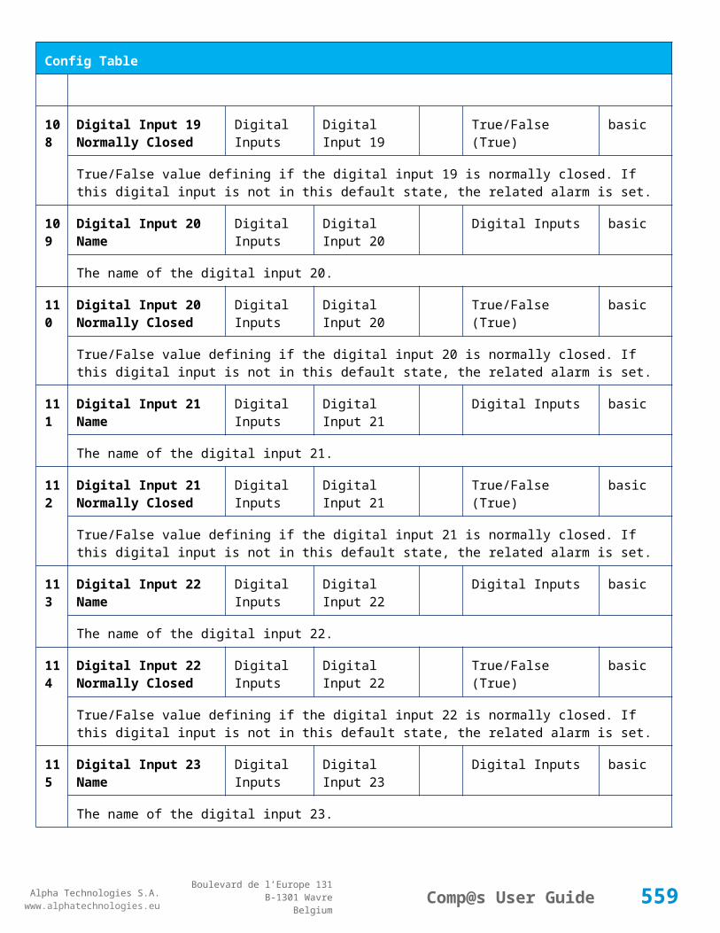
Alpha Technologies S.A.www.alphatechnologies.eu
Alpha Technologies S.A.www.alphatechnologies.eu
Comp@s User GuideBoulevard de l’Europe 131
B-1301 WavreBelgium
Config Table
The name of the digital input 2.
74 Digital Input 2 Normally Closed
Digital Inputs Digital Input 2 True/False (True) basic
True/False value defining if the digital input 2 is normally closed. If this digital input is not in this default state, the related alarm is set.
75 Digital Input 3 Name Digital Inputs Digital Input 3 Digital Inputs basic
The name of the digital input 3.
76 Digital Input 3 Normally Closed
Digital Inputs Digital Input 3 True/False (True) basic
True/False value defining if the digital input 3 is normally closed. If this digital input is not in this default state, the related alarm is set.
77 Digital Input 4 Name Digital Inputs Digital Input 4 Digital Inputs basic
The name of the digital input 4.
78 Digital Input 4 Normally Closed
Digital Inputs Digital Input 4 True/False (True) basic
True/False value defining if the digital input 4 is normally closed. If this digital input is not in this default state, the related alarm is set.
79 Digital Input 5 Name Digital Inputs Digital Input 5 Digital Inputs basic
The name of the digital input 5.
80 Digital Input 5 Normally Closed
Digital Inputs Digital Input 5 True/False (True) basic
True/False value defining if the digital input 5 is normally closed. If this digital input is not in this default state, the related alarm is set.
81 Digital Input 6 Name Digital Inputs Digital Input 6 Digital Inputs basic
The name of the digital input 6.
82 Digital Input 6 Normally Closed
Digital Inputs Digital Input 6 True/False (True) basic
True/False value defining if the digital input 6 is normally closed. If this digital input is not in this default state, the related alarm is set.
83 Digital Input 7 Name Digital Inputs Digital Input 7 Digital Inputs basic
The name of the digital input 7.
84 Digital Input 7 Normally Closed
Digital Inputs Digital Input 7 True/False (True) basic
559

Alpha Technologies S.A.www.alphatechnologies.eu
Alpha Technologies S.A.www.alphatechnologies.eu
Comp@s User GuideBoulevard de l’Europe 131
B-1301 WavreBelgium
Config Table
True/False value defining if the digital input 7 is normally closed. If this digital input is not in this default state, the related alarm is set.
85 Digital Input 8 Name Digital Inputs Digital Input 8 Digital Inputs basic
The name of the digital input 8.
86 Digital Input 8 Normally Closed
Digital Inputs Digital Input 8 True/False (True) basic
True/False value defining if the digital input 8 is normally closed. If this digital input is not in this default state, the related alarm is set.
87 Digital Input 9 Name Digital Inputs Digital Input 9 Digital Inputs basic
The name of the digital input 9.
88 Digital Input 9 Normally Closed
Digital Inputs Digital Input 9 True/False (True) basic
True/False value defining if the digital input 9 is normally closed. If this digital input is not in this default state, the related alarm is set.
89 Digital Input 10 Name Digital Inputs Digital Input 10 Digital Inputs basic
The name of the digital input 10.
90 Digital Input 10 Normally Closed
Digital Inputs Digital Input 10 True/False (True) basic
True/False value defining if the digital input 10 is normally closed. If this digital input is not in this default state, the related alarm is set.
91 Digital Input 11 Name Digital Inputs Digital Input 11 Digital Inputs basic
The name of the digital input 11.
92 Digital Input 11 Normally Closed
Digital Inputs Digital Input 11 True/False (True) basic
True/False value defining if the digital input 11 is normally closed. If this digital input is not in this default state, the related alarm is set.
93 Digital Input 12 Name Digital Inputs Digital Input 12 Digital Inputs basic
The name of the digital input 12.
94 Digital Input 12 Normally Closed
Digital Inputs Digital Input 12 True/False (True) basic
True/False value defining if the digital input 12 is normally closed. If this digital input is not in this default state, the related alarm is set.
12 Relay 1 Change State Digital basic
560
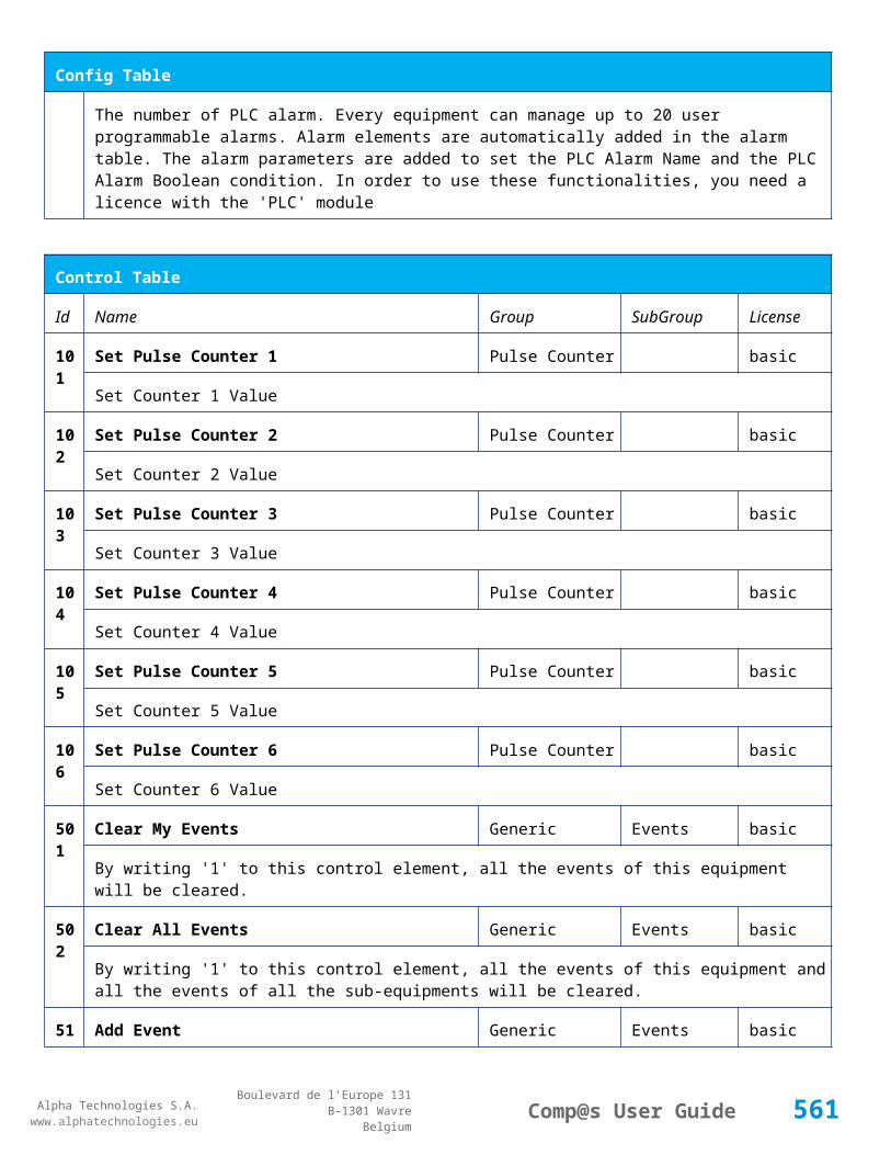
Alpha Technologies S.A.www.alphatechnologies.eu
Alpha Technologies S.A.www.alphatechnologies.eu
Comp@s User GuideBoulevard de l’Europe 131
B-1301 WavreBelgium
Config Table
1 Boolan Condition Outputs
PLC Boolean condition to energize the relay 01
122
Relay 2 Change State Boolan Condition
Digital Outputs
basic
PLC Boolean condition to energize the relay 11
123
Relay 3 Change State Boolan Condition
Digital Outputs
basic
PLC Boolean condition to energize the relay 21
124
Relay 4 Change State Boolan Condition
Digital Outputs
basic
PLC Boolean condition to energize the relay 31
521
Read Access User Numbers
Generic Allowed Users (1,2,3,4,5) basic
The list of the user numbers which have read access to this equipment. The user numbers are coma separated. The accepted user id are 1,2,3,4 and 5. Ex: 1,3,4
522
Write Access User Numbers
Generic Allowed Users () basic
The list of the user numbers which have write access to this equipment. This means that these users can modify the configuration element, the alarm settings and use the control elements. The user numbers are coma separated. The accepted user ids are 1,2,3,4 and 5. Ex: 1,3,4
601
Event Table Length Generic Events 10/4000 (100) basic
The maximum length of the table. The value must be comprised between 10 and 4000
901
Number Of PLC Data PLC (0) plc
The number of PLC data. Every equipment can manage up to 20 user programmable data. Data elements are automatically added in the data table. Configuration parameters are added to set the PLC Data Name and the PLC Data Mathematical calculation. In order to use these functionalities, you need a license with the 'PLC' module
902
Number Of PLC Alarm PLC (0) plc
The number of PLC alarm. Every equipment can manage up to 20 user programmable alarms. Alarm elements are automatically added in the alarm table. The alarm parameters are added to set the PLC Alarm Name and the PLC Alarm Boolean condition. In order to use these functionalities, you need a licence with the 'PLC' module
561

Alpha Technologies S.A.www.alphatechnologies.eu
Alpha Technologies S.A.www.alphatechnologies.eu
Comp@s User GuideBoulevard de l’Europe 131
B-1301 WavreBelgium
Control Table
Id Name Group SubGroup License
501
Clear My Events Generic Events basic
By writing '1' to this control element, all the events of this equipment will be cleared.
502
Clear All Events Generic Events basic
By writing '1' to this control element, all the events of this equipment and all the events of all the sub-equipments will be cleared.
511
Add Event Generic Events basic
This control element adds an event of severity none. The event name is the text written to this control element
512
Add Major Event Generic Events basic
This control element adds an event of severity major. The event name is the text written to this control element
521
Reset Default Names And Groups Generic Renaming basic
This control element resets all the element Names, Groups and Subgroups to default values for this equipment
522
Reset Default Names And Groups Recursive Generic Renaming basic
This control element resets all the element Names, Groups and Subgroups to default values for this equipment and all sub equipments
7.4.11 SAM0948
Device Information
Name SAM0948
Short Description
Site management card
Long Description
Site and infrastructure management card, 2 connections (RJ25) for card reader and door lock and 1 I/O connector (Sub-D26) - Captin FA and Captin BW lines
Hardware Reference
9413 060 95131
Software Reference
SOFT 000003 XX
Equipment Type
System Extension
562

Alpha Technologies S.A.www.alphatechnologies.eu
Alpha Technologies S.A.www.alphatechnologies.eu
Comp@s User GuideBoulevard de l’Europe 131
B-1301 WavreBelgium
Device Information
ETSI Level /site/sensors_and_actuators
Description Table
Id Name Group SubGroup License
1 Product Name Description Product Info basic
The commercial name of the extension card.
2 Hardware Reference Description Product Info basic
The hardware refence
3 Hardware Revision Description Product Info basic
The hardware revision
4 Software Reference Description Product Info basic
The software reference
6 Serial Number Description Product Info basic
The serial number.
8 Manufacturing Date Description Product Info basic
The production date.
11 Description Description Custom Description basic
A free text zone to write a system description
12 Reference Description Custom Description basic
A free text zone to write the customer reference of the system
Alarm Table
Id Name Group SubGroup Severity Type (Level)
Set/Clear Delay
1 Cabinet Temperature High major (6) 5 / 2
The temperature of the cabinet is too high.
2 Cabinet Temperature Low major (6) 5 / 2
The temperature of the cabinet is too low.
563

Alpha Technologies S.A.www.alphatechnologies.eu
Alpha Technologies S.A.www.alphatechnologies.eu
Comp@s User GuideBoulevard de l’Europe 131
B-1301 WavreBelgium
Alarm Table
3 Cabinet Temperature Sensor Fail
minor (4) 5 / 2
The cabinet temperature sense is defect.
11
Cabinet Humidity High major (6) 5 / 2
The cabinet humidity is too high
12
Cabinet Humidity Low major (6) 5 / 2
The cabinet humidity is too low
21
Water Detection Alarm major (6) 5 / 2
Water is detected by the water sensor.
31
Tilt X Alarm major (6) 5 / 2
The X-tilt absolute value is too high
32
Tilt Y Alarm major (6) 5 / 2
The Y-tilt absolute value is too high
41
Vandalism Alarm major (6) 5 / 2
The vandalism score is too high
51
Badge Reader Failure major (6) 5 / 2
The badge reader is defect or not connected
71
Digital Input 1 Digital Inputs
Digital Input 1 warning (0) 5 / 2
The name of the digital input 1 alarm.
72
Digital Input 2 Digital Inputs
Digital Input 2 warning (0) 5 / 2
The name of the digital input 2 alarm.
73
Digital Input 3 Digital Inputs
Digital Input 3 warning (0) 5 / 2
The name of the digital input 3 alarm.
74
Digital Input 4 Digital Inputs
Digital Input 4 warning (0) 5 / 2
The name of the digital input 4 alarm.
7 Digital Input 5 Digital Digital Input 5 warning (0) 5 / 2
564

Alpha Technologies S.A.www.alphatechnologies.eu
Alpha Technologies S.A.www.alphatechnologies.eu
Comp@s User GuideBoulevard de l’Europe 131
B-1301 WavreBelgium
Alarm Table
5 Inputs
The name of the digital input 5 alarm.
76
Digital Input 6 Digital Inputs
Digital Input 6 warning (0) 5 / 2
The name of the digital input 6 alarm.
77
Digital Input 7 Digital Inputs
Digital Input 7 warning (0) 5 / 2
The name of the digital input 7 alarm.
78
Digital Input 8 Digital Inputs
Digital Input 8 warning (0) 5 / 2
The name of the digital input 8 alarm.
79
Digital Input 9 Digital Inputs
Digital Input 9 warning (0) 5 / 2
The name of the digital input 9 alarm.
80
Digital Input 10 Digital Inputs
Digital Input 10
warning (0) 5 / 2
The name of the digital input 10 alarm.
Data Table
Id Name Group SubGroup Unit License
1 Cabinet Temperature Sensors degree C basic
The temperature in the cabinet
11 Relative Humidity Sensors % basic
The relative humidity in the cabinet
21 Tilt X Sensors degree basic
The tilt-X value
22 Tilt Y Sensors degree basic
The tilt-Y value
31 Vandalism Score Sensors basic
The vandalism score. This depends of the cabinet acceleration over time.
565

Alpha Technologies S.A.www.alphatechnologies.eu
Alpha Technologies S.A.www.alphatechnologies.eu
Comp@s User GuideBoulevard de l’Europe 131
B-1301 WavreBelgium
Data Table
41 Last UID Badge Reader Badge Reader basic
The last uid value read by the badge reader
42 Last Time Badge Reader Badge Reader basic
The date and time at which the badge reader has been used
52 Lock 1 Open Access Control 1 basic
The lock 1 is mechanically closed
53 Lock 1 Enabled Access Control 1 basic
The access control 1 is enabling the electronic lock 1
62 Lock 2 Open Access Control 2 basic
The lock 2 is mechanically closed
63 Lock 2 Enabled Access Control 2 basic
The access control 2 is enabling the electronic lock 2
71 Digital Input 1 State Digital Inputs Digital Input 1 basic
The state of the digital input
72 Digital Input 2 State Digital Inputs Digital Input 2 basic
The state of the digital input
73 Digital Input 3 State Digital Inputs Digital Input 3 basic
The state of the digital input
74 Digital Input 4 State Digital Inputs Digital Input 4 basic
The state of the digital input
75 Digital Input 5 State Digital Inputs Digital Input 5 basic
The state of the digital input
76 Digital Input 6 State Digital Inputs Digital Input 6 basic
The state of the digital input
77 Digital Input 7 State Digital Inputs Digital Input 7 basic
The state of the digital input
78 Digital Input 8 State Digital Inputs Digital Input 8 basic
566
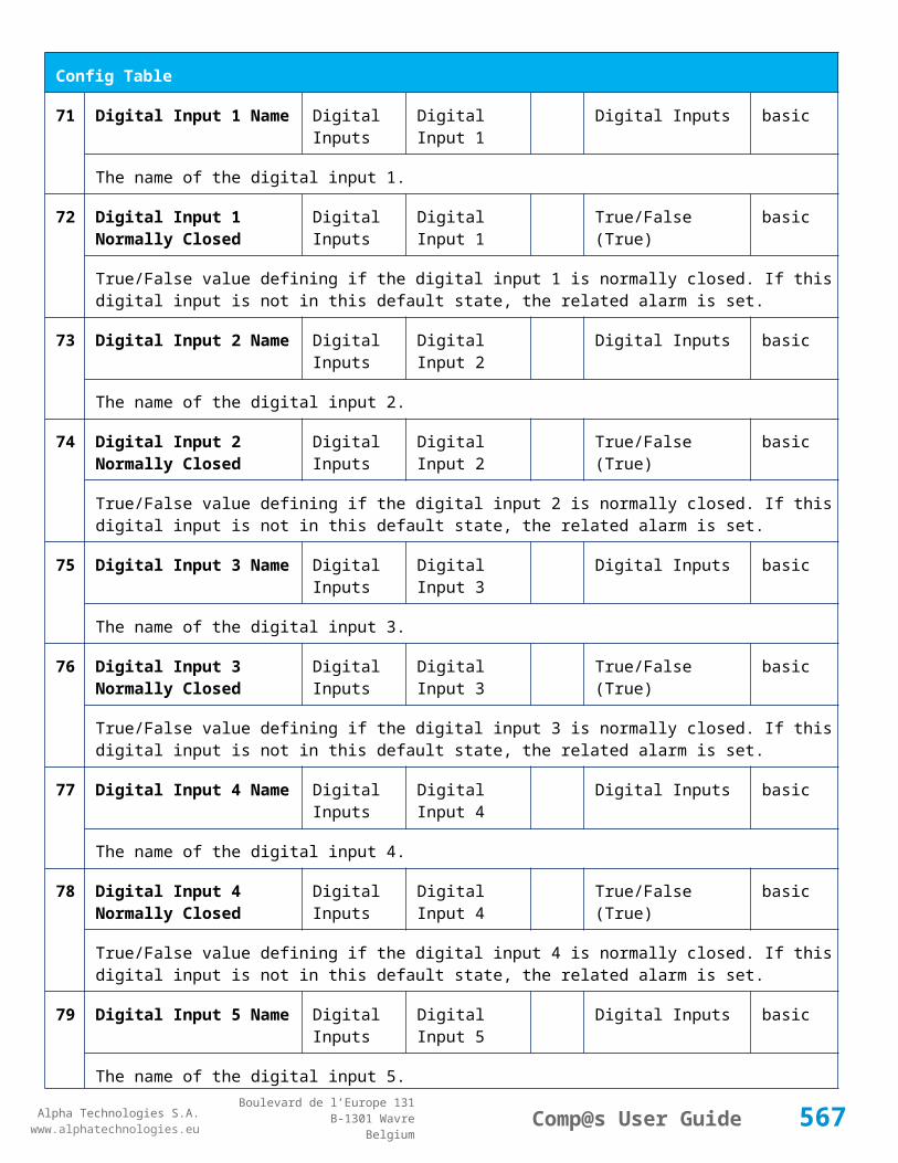
Alpha Technologies S.A.www.alphatechnologies.eu
Alpha Technologies S.A.www.alphatechnologies.eu
Comp@s User GuideBoulevard de l’Europe 131
B-1301 WavreBelgium
Data Table
The state of the digital input
79 Digital Input 9 State Digital Inputs Digital Input 9 basic
The state of the digital input
80 Digital Input 10 State Digital Inputs Digital Input 10 basic
The state of the digital input
Config Table
Id Name Group SubGroup Unit Range: Min/Max (default)
License
1 Cabinet Temperature High Alarm Parameters
degree C -50/100 (50) basic
The temperature over which the cabinet temperature is too high
2 Cabinet Temperature Low Alarm Parameters
degree C -50/100 (-5) basic
The temperature under which the cabinet temperature is too low
3 Temperature Hysteresis Alarm Parameters
degree C 0/20 (1) basic
The hysteresis on the temperature alarm
11 Cabinet Humidity High Alarm Parameters
% 0/100 (80) basic
The relative humidity over which the cabinet humidity is too high
12 Cabinet Humidity Low Alarm Parameters
% 0/100 (0) basic
The relative humidity over which the cabinet humidity is too low
13 Humidity Alarm Hysteresis
Alarm Parameters
% 0/50 (2) basic
The hysteresis on the humidty alarms, in percent
21 Tilt X High Alarm Parameters
degree 0/90 (10) basic
The maximum absolute tilt-X value allowed for the cabinet
22 Tilt Y High Alarm Parameters
degree 0/90 (10) basic
567
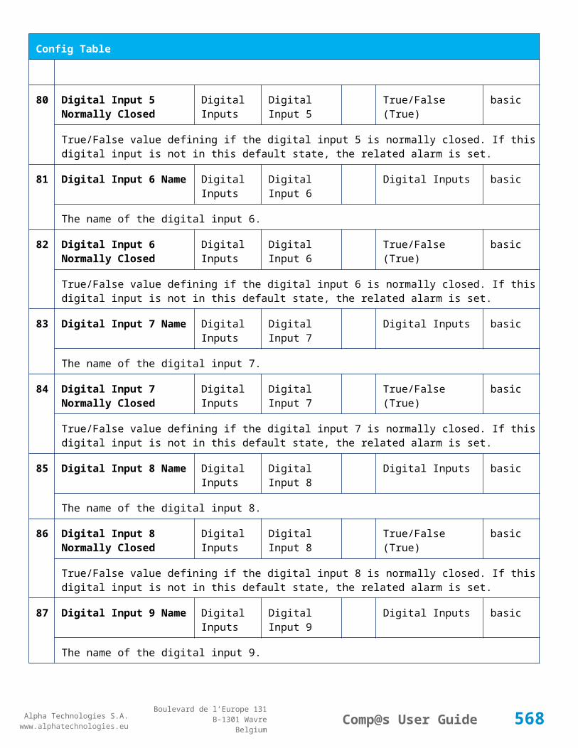
Alpha Technologies S.A.www.alphatechnologies.eu
Alpha Technologies S.A.www.alphatechnologies.eu
Comp@s User GuideBoulevard de l’Europe 131
B-1301 WavreBelgium
Config Table
The maximum absolute tilt-Y value allowed for the cabinet
23 Tilt Alarm Hysteresis Alarm Parameters
degree 0/45 (2) basic
The hysteresis on tilt X/Y alarms
31 Vandalism Detection Threshold
Alarm Parameters
basic
The maximum vandalism score allowed for the cabinet.
41 Access Control 1 Enabled Access Control 1
True/False (False)
basic
The access control 1 is enabled. The electronic lock 1 must be managed.
42 Access Control 1 Authorized UID
Access Control 1
basic
Coma separated list of the UID allowed to disable the electronic lock 1
43 Access Control 1 Auto Close Time
Access Control 1
second 0/1000 (30) basic
Time in second after which the electronic lock 1 must be automatically locked again
44 Access Control 1 Disabled If Badge Reader Failure
Access Control 1
True/False (True)
basic
The electronic lock 1 must be disabled if the 'Badge reader failure' alarm is set.
45 Access Control 1 Doors Inputs
Access Control 1
(7,9,10) basic
This is the coma separated list of the digital inputs which are door contacts related to the access control 1
51 Access Control 2 Enabled Access Control 2
True/False (False)
basic
The access control 2 is enabled. The electronic lock 2 must be managed.
52 Access Control 2 Authorized UID
Access Control 2
basic
Coma separated list of the UID allowed to disable the electronic lock 2
53 Access Control 2 Auto Close Time
Access Control 2
second 0/1000 (30) basic
Time in second after which the electronic lock 2 must be automatically locked again
54 Access Control 2 Disabled Access Control True/False basic
568

Alpha Technologies S.A.www.alphatechnologies.eu
Alpha Technologies S.A.www.alphatechnologies.eu
Comp@s User GuideBoulevard de l’Europe 131
B-1301 WavreBelgium
Config Table
If Badge Reader Failure 2 (True)
The electronic lock 1 must be disabled if the 'Badge reader failure' alarm is set.
55 Access Control 2 Doors Inputs
Access Control 2
(8) basic
This is the coma separated list of the digital inputs which are door contacts related to the access control 2
71 Digital Input 1 Name Digital Inputs Digital Input 1
Digital Inputs basic
The name of the digital input 1.
72 Digital Input 1 Normally Closed
Digital Inputs Digital Input 1
True/False (True)
basic
True/False value defining if the digital input 1 is normally closed. If this digital input is not in this default state, the related alarm is set.
73 Digital Input 2 Name Digital Inputs Digital Input 2
Digital Inputs basic
The name of the digital input 2.
74 Digital Input 2 Normally Closed
Digital Inputs Digital Input 2
True/False (True)
basic
True/False value defining if the digital input 2 is normally closed. If this digital input is not in this default state, the related alarm is set.
75 Digital Input 3 Name Digital Inputs Digital Input 3
Digital Inputs basic
The name of the digital input 3.
76 Digital Input 3 Normally Closed
Digital Inputs Digital Input 3
True/False (True)
basic
True/False value defining if the digital input 3 is normally closed. If this digital input is not in this default state, the related alarm is set.
77 Digital Input 4 Name Digital Inputs Digital Input 4
Digital Inputs basic
The name of the digital input 4.
78 Digital Input 4 Normally Closed
Digital Inputs Digital Input 4
True/False (True)
basic
True/False value defining if the digital input 4 is normally closed. If this digital input is not in this default state, the related alarm is set.
569

Alpha Technologies S.A.www.alphatechnologies.eu
Alpha Technologies S.A.www.alphatechnologies.eu
Comp@s User GuideBoulevard de l’Europe 131
B-1301 WavreBelgium
Config Table
79 Digital Input 5 Name Digital Inputs Digital Input 5
Digital Inputs basic
The name of the digital input 5.
80 Digital Input 5 Normally Closed
Digital Inputs Digital Input 5
True/False (True)
basic
True/False value defining if the digital input 5 is normally closed. If this digital input is not in this default state, the related alarm is set.
81 Digital Input 6 Name Digital Inputs Digital Input 6
Digital Inputs basic
The name of the digital input 6.
82 Digital Input 6 Normally Closed
Digital Inputs Digital Input 6
True/False (True)
basic
True/False value defining if the digital input 6 is normally closed. If this digital input is not in this default state, the related alarm is set.
83 Digital Input 7 Name Digital Inputs Digital Input 7
Digital Inputs basic
The name of the digital input 7.
84 Digital Input 7 Normally Closed
Digital Inputs Digital Input 7
True/False (True)
basic
True/False value defining if the digital input 7 is normally closed. If this digital input is not in this default state, the related alarm is set.
85 Digital Input 8 Name Digital Inputs Digital Input 8
Digital Inputs basic
The name of the digital input 8.
86 Digital Input 8 Normally Closed
Digital Inputs Digital Input 8
True/False (True)
basic
True/False value defining if the digital input 8 is normally closed. If this digital input is not in this default state, the related alarm is set.
87 Digital Input 9 Name Digital Inputs Digital Input 9
Digital Inputs basic
The name of the digital input 9.
88 Digital Input 9 Normally Closed
Digital Inputs Digital Input 9
True/False (True)
basic
True/False value defining if the digital input 9 is normally closed. If this digital input is not in this default state, the related alarm is set.
570
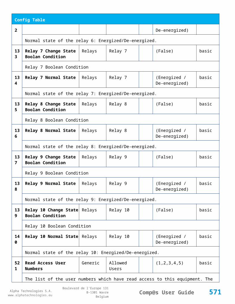
Alpha Technologies S.A.www.alphatechnologies.eu
Alpha Technologies S.A.www.alphatechnologies.eu
Comp@s User GuideBoulevard de l’Europe 131
B-1301 WavreBelgium
Config Table
89 Digital Input 10 Name Digital Inputs Digital Input 10
Digital Inputs basic
The name of the digital input 10.
90 Digital Input 10 Normally Closed
Digital Inputs Digital Input 10
True/False (True)
basic
True/False value defining if the digital input 10 is normally closed. If this digital input is not in this default state, the related alarm is set.
121
Digital Output Relay 1 Energized Boolan Condition
Relays Relay 1 basic
PLC Boolean condition to energize the relay 1
521
Read Access User Numbers
Generic Allowed Users
(1,2,3,4,5) basic
The list of the user numbers which have read access to this equipment. The user numbers are coma separated. The accepted user id are 1,2,3,4 and 5. Ex: 1,3,4
522
Write Access User Numbers
Generic Allowed Users
() basic
The list of the user numbers which have write access to this equipment. This means that these users can modify the configuration element, the alarm settings and use the control elements. The user numbers are coma separated. The accepted user ids are 1,2,3,4 and 5. Ex: 1,3,4
601
Event Table Length Generic Events 10/4000 (100) basic
The maximum length of the table. The value must be comprised between 10 and 4000
901
Number Of PLC Data PLC (0) plc
The number of PLC data. Every equipment can manage up to 20 user programmable data. Data elements are automatically added in the data table. Configuration parameters are added to set the PLC Data Name and the PLC Data Mathematical calculation. In order to use these functionalities, you need a license with the 'PLC' module
902
Number Of PLC Alarm PLC (0) plc
The number of PLC alarm. Every equipment can manage up to 20 user programmable alarms. Alarm elements are automatically added in the alarm table. The alarm parameters are added to set the PLC Alarm Name and the PLC Alarm Boolean condition. In order to use these functionalities, you need a licence with the 'PLC' module
Control Table
Id Name Group SubGroup License
571
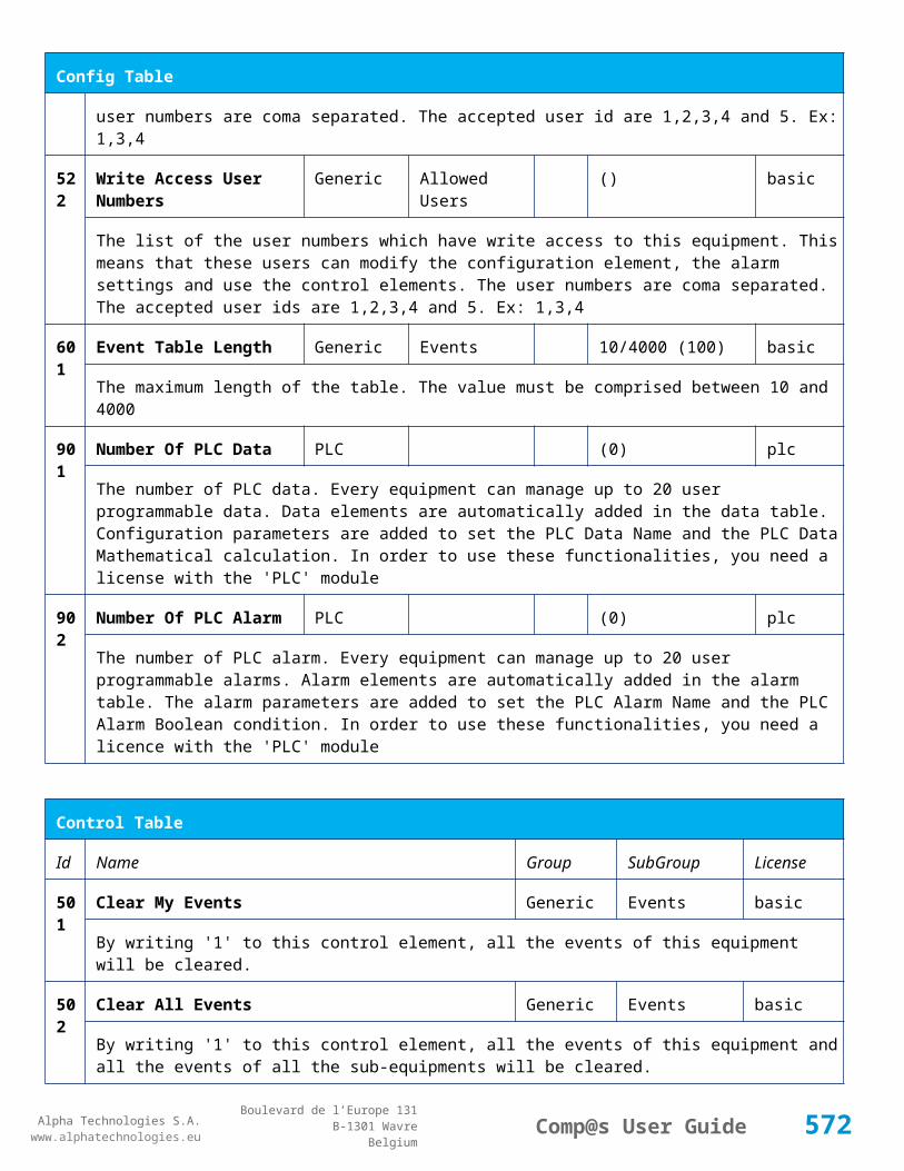
Alpha Technologies S.A.www.alphatechnologies.eu
Alpha Technologies S.A.www.alphatechnologies.eu
Comp@s User GuideBoulevard de l’Europe 131
B-1301 WavreBelgium
Control Table
1 Unlock Door 1 Lock Control basic
Electronic lock 1 must be disabled
2 Unlock Door 2 Lock Control basic
Electronic lock 2 must be disabled
11 Lock Door 1 Lock Control basic
Electronic lock 1 must be enabled
12 Lock Door 2 Lock Control basic
Electronic lock 2 must be enabled
31 Auto Calibrate Tilt Zero Calibration basic
The tilt-X and tilt-Y must be calibrated to 0 with the actual tilt.
501
Clear My Events Generic Events basic
By writing '1' to this control element, all the events of this equipment will be cleared.
502
Clear All Events Generic Events basic
By writing '1' to this control element, all the events of this equipment and all the events of all the sub-equipments will be cleared.
511
Add Event Generic Events basic
This control element adds an event of severity none. The event name is the text written to this control element
512
Add Major Event Generic Events basic
This control element adds an event of severity major. The event name is the text written to this control element
521
Reset Default Names And Groups Generic Renaming basic
This control element resets all the element Names, Groups and Subgroups to default values for this equipment
522
Reset Default Names And Groups Recursive Generic Renaming basic
This control element resets all the element Names, Groups and Subgroups to default values for this equipment and all sub equipments
572

Alpha Technologies S.A.www.alphatechnologies.eu
Alpha Technologies S.A.www.alphatechnologies.eu
Comp@s User GuideBoulevard de l’Europe 131
B-1301 WavreBelgium
7.5 Remote Power Feeding System Tables
7.5.1 CEM03_Remote_Power_Feeding_System
Device Information
Name CEM03_Remote_Power_Feeding_System
Short Description Monitoring for Central Up Converter system
Long Description Central monitoring card for 4 down converter cards with CAN IN/CAN OUT and 4 relays
Hardware Reference
9413 044 89421
Software Reference SOFT 000022 XX
Equipment Type Monitoring For Remote (About Remote Power Feeding System)
ETSI Level /site/energy_system/remote_power_feeding_system
Description Table
Id Name Group License
1 Description Description basic
A free text zone to write a system description
2 Reference Description basic
A free text zone to write the customer reference of the system
Config Table
Id
Name Group Unit Range: Min/Max (default) License
1 Number of CEM03 By Shelf Up Converters basic
Maximum number of CEM03 cards that are authorized by shelf. This parameter value must be comprised between 1 and 4.
573

Alpha Technologies S.A.www.alphatechnologies.eu
Alpha Technologies S.A.www.alphatechnologies.eu
Comp@s User GuideBoulevard de l’Europe 131
B-1301 WavreBelgium
7.5.2 CEM03 Remote Power Feeding_System
Device Information
Name CEM03 Remote Power Feeding_System
Short Description Monitoring for Central Up Converter system
Long Description Central monitoring card for 4 down converter cards with CAN IN/CAN OUT and 4 relays
Hardware Reference
9413 044 89421
Software Reference SOFT 000022 XX
Equipment Type Monitoring For Remote (About Remote Power Feeding System)
ETSI Level /site/energy_system/remote_power_feeding_system
7.6 Up Converter System Tables
7.6.1 CEM03_Up_Converter_System
Device Information
Name CEM03_Up_Converter_System
Short Description Monitoring for Central Up Converter system
Long Description Central monitoring card for 4 down converter cards with CAN IN/CAN OUT and 4 relays
Hardware Reference
9413 044 89421
Software Reference SOFT 000022 XX
Equipment Type Monitoring For Remote (About Up Converter System)
ETSI Level /site/energy_system/remote_power_feeding_system/up_converter_system
Description Table
Id Name Group License
1 Description Description basic
A free text zone to write a system description
574
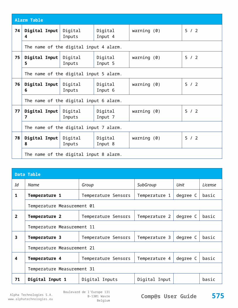
Alpha Technologies S.A.www.alphatechnologies.eu
Alpha Technologies S.A.www.alphatechnologies.eu
Comp@s User GuideBoulevard de l’Europe 131
B-1301 WavreBelgium
Description Table
2 Reference Description basic
A free text zone to write the customer reference of the system
11 Product Name Monitoring basic
The product name of the DC system monitoring
12 Hardware Reference Monitoring basic
The hardware reference of the DC system monitoring
14 Software Reference Monitoring asset
The serial number of the DC system monitoring
16 Serial Number Monitoring asset
The serial number of the DC system monitoring
17 Manufacturing ID Monitoring asset
The batch id of the DC system monitoring
18 Manufacturing Date Monitoring asset
The production date of the DC system monitoring
Alarm Table
Id Name Severity Type (Level) Set/Clear Delay
1 One Up Converter Failure minor (4) 5 / 2
One Up converter is defect or not connected to a down converter (and enabled)
2 More Than One Up Converter Failure major (6) 5 / 2
More than one Up converter is defect or not connected to a down converter (and enabled)
3 More Than One Up Converter Card Failure major (6) 5 / 2
More than one up converter card is defect or not connected to a down converter (and enabled)
11 One FAN Failure minor (4) 5 / 2
One FAN has a problem
12 More Than One FAN Failure major (6) 5 / 2
More Than One FAN has a problem
575
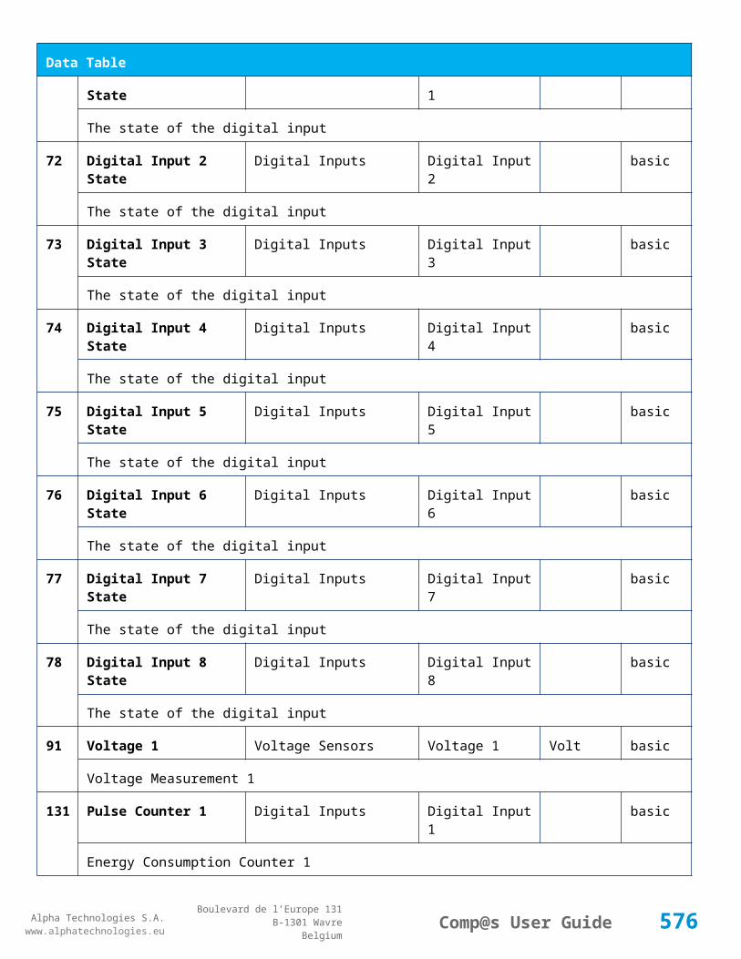
Alpha Technologies S.A.www.alphatechnologies.eu
Alpha Technologies S.A.www.alphatechnologies.eu
Comp@s User GuideBoulevard de l’Europe 131
B-1301 WavreBelgium
Alarm Table
14 Configuration Problem minor (4) 5 / 2
There is a configuration problem. A card is configuted but not available
20 Slot 0 Alarm minor (4) 15 / 15
Slot 0 is in alarm
21 Slot 1 Alarm minor (4) 15 / 15
Slot 1 is in alarm
22 Slot 2 Alarm minor (4) 15 / 15
Slot 2 is in alarm
23 Slot 3 Alarm minor (4) 15 / 15
Slot 3 is in alarm
24 Slot 4 Alarm minor (4) 15 / 15
Slot 4 is in alarm
25 Slot 5 Alarm minor (4) 15 / 15
Slot 5 is in alarm
26 Slot 6 Alarm minor (4) 15 / 15
Slot 6 is in alarm
27 Slot 7 Alarm minor (4) 15 / 15
Slot 7 is in alarm
28 Slot 8 Alarm minor (4) 15 / 15
Slot 8 is in alarm
29 Slot 9 Alarm minor (4) 15 / 15
Slot 9 is in alarm
30 Slot 10 Alarm minor (4) 15 / 15
Slot 10 is in alarm
31 Slot 11 Alarm minor (4) 15 / 15
Slot 11 is in alarm
32 Slot 12 Alarm minor (4) 15 / 15
576

Alpha Technologies S.A.www.alphatechnologies.eu
Alpha Technologies S.A.www.alphatechnologies.eu
Comp@s User GuideBoulevard de l’Europe 131
B-1301 WavreBelgium
Alarm Table
Slot 12 is in alarm
33 Slot 13 Alarm minor (4) 15 / 15
Slot 13 is in alarm
34 Slot 14 Alarm minor (4) 15 / 15
Slot 14 is in alarm
35 Slot 15 Alarm minor (4) 15 / 15
Slot 15 is in alarm
36 Slot 16 Alarm minor (4) 15 / 15
Slot 16 is in alarm
Data Table
Id Name Group Unit License
1 Input Voltage Rack Volt basic
No information
2 Temperature Rack degree C basic
No information
12 Number Of Up Converter NOK Up Converters basic
No information
13 Number Of Up Converter Card NOK Up Converters basic
No information
20 Status Slot 0 Slots Status basic
No information
21 Status Slot 1 Slots Status basic
No information
22 Status Slot 2 Slots Status basic
No information
23 Status Slot 3 Slots Status basic
577

Alpha Technologies S.A.www.alphatechnologies.eu
Alpha Technologies S.A.www.alphatechnologies.eu
Comp@s User GuideBoulevard de l’Europe 131
B-1301 WavreBelgium
Data Table
No information
24 Status Slot 4 Slots Status basic
No information
25 Status Slot 5 Slots Status basic
No information
26 Status Slot 6 Slots Status basic
No information
27 Status Slot 7 Slots Status basic
No information
28 Status Slot 8 Slots Status basic
No information
29 Status Slot 9 Slots Status basic
No information
30 Status Slot 10 Slots Status basic
No information
31 Status Slot 11 Slots Status basic
No information
32 Status Slot 12 Slots Status basic
No information
33 Status Slot 13 Slots Status basic
No information
34 Status Slot 14 Slots Status basic
No information
35 Status Slot 15 Slots Status basic
No information
36 Status Slot 16 Slots Status basic
No information
578

Alpha Technologies S.A.www.alphatechnologies.eu
Alpha Technologies S.A.www.alphatechnologies.eu
Comp@s User GuideBoulevard de l’Europe 131
B-1301 WavreBelgium
Data Table
51 Powered Site Ids Monitoring basic
No information
52 Monitored Site Ids Monitoring basic
No information
53 Powered Site Ids with Possible Line Feed Problem Monitoring basic
No information
Config Table
Id Name Group Unit
Range: Min/Max (default)
License
20
Slot 0 Config Site
basic
No information
21
Slot 1 Config Site
basic
No information
22
Slot 2 Config Site
basic
No information
23
Slot 3 Config Site
basic
No information
24
Slot 4 Config Site
basic
No information
25
Slot 5 Config Site
basic
No information
26
Slot 6 Config Site
basic
No information
579
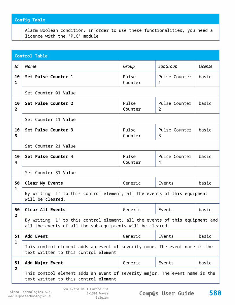
Alpha Technologies S.A.www.alphatechnologies.eu
Alpha Technologies S.A.www.alphatechnologies.eu
Comp@s User GuideBoulevard de l’Europe 131
B-1301 WavreBelgium
Config Table
27
Slot 7 Config Site
basic
No information
28
Slot 8 Config Site
basic
No information
29
Slot 9 Config Site
basic
No information
30
Slot 10 Config Site
basic
No information
31
Slot 11 Config Site
basic
No information
32
Slot 12 Config Site
basic
No information
33
Slot 13 Config Site
basic
No information
34
Slot 14 Config Site
basic
No information
35
Slot 15 Config Site
basic
No information
36
Slot 16 Config Site
basic
No information
51
Urgent Relay Energized Boolean Condition Relays basic
No information
580

Alpha Technologies S.A.www.alphatechnologies.eu
Alpha Technologies S.A.www.alphatechnologies.eu
Comp@s User GuideBoulevard de l’Europe 131
B-1301 WavreBelgium
Config Table
52
Non Urgent Relay Energized Boolean Condition
Relays basic
No information
Control Table
Id Name Group License
501
Clear My Events Event basic
By writing '1' to this control element, all the events of this equipment will be cleared.
502
Clear All Events Event basic
By writing '1' to this control element, all the events of this equipment and all the events of all the sub-equipments will be cleared.
511
Add Event Event basic
This control element adds an event of severity none. The event name is the text written to this control element
512
Add Major Event Event basic
This control element adds an event of severity major. The event name is the text written to this control element
521
Reset Default Names And Groups Advanced basic
This control element resets all the element Names, Groups and Subgroups to default values for this equipment
522
Reset Default Names And Groups Recursive Advanced basic
This control element resets all the element Names, Groups and Subgroups to default values for this equipment and all sub equipments
7.6.2 CEM03 Up Converter_System
Device Information
Name CEM03 Up Converter_System
Short Description Monitoring for Central Up Converter system
Long Description Central monitoring card for 4 down converter cards with CAN IN/CAN OUT and 4 relays
581

Alpha Technologies S.A.www.alphatechnologies.eu
Alpha Technologies S.A.www.alphatechnologies.eu
Comp@s User GuideBoulevard de l’Europe 131
B-1301 WavreBelgium
Device Information
Hardware Reference
9413 044 89421
Software Reference SOFT 000022 XX
Equipment Type Monitoring For Remote (About Up Converter System)
ETSI Level /site/energy_system/remote_power_feeding_system/up_converter_system
Description Table
Id Name Group SubGroup License
1 Description Description Custom Description basic
A free text zone to write a system description
2 Reference Description Custom Description basic
A free text zone to write the customer reference of the system
11 Product Name Monitoring basic
The product name of the DC system monitoring
12 Hardware Reference Monitoring basic
The hardware reference of the DC system monitoring
14 Software Reference Monitoring asset
The serial number of the DC system monitoring
16 Serial Number Monitoring asset
The serial number of the DC system monitoring
18 Manufacturing Date Monitoring asset
The production date of the DC system monitoring
Alarm Table
Id Name Group SubGroup
Severity Type (Level)
Set/Clear Delay
1 One Up Converter Failure Up Converters
minor (4) 5 / 2
One Up converter is defect or not connected to a down converter (and enabled)
582
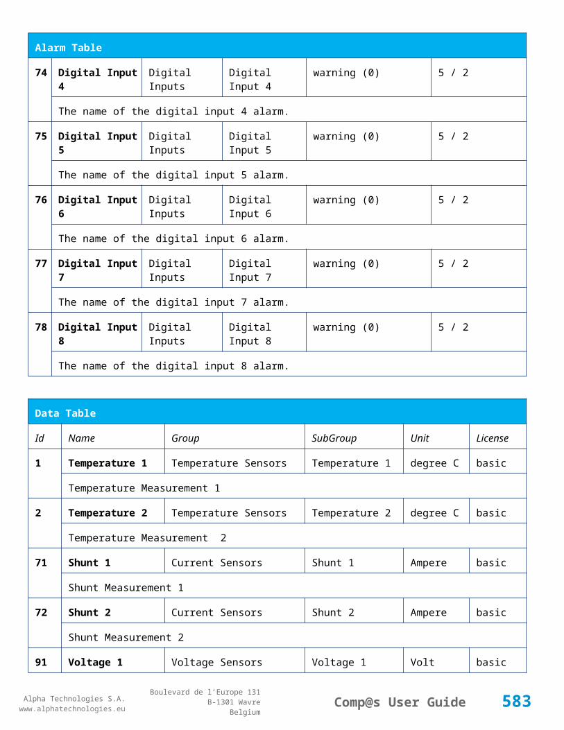
Alpha Technologies S.A.www.alphatechnologies.eu
Alpha Technologies S.A.www.alphatechnologies.eu
Comp@s User GuideBoulevard de l’Europe 131
B-1301 WavreBelgium
Alarm Table
2 More Than One Up Converter Failure Up Converters
major (6) 5 / 2
More than one Up converter is defect or not connected to a down converter (and enabled)
3 More Than One Up Converter Card Failure
Up Converters
major (6) 5 / 2
More than one up converter card is defect or not connected to a down converter (and enabled)
11
One FAN Failure Up Converters
minor (4) 5 / 2
One FAN has a problem
12
More Than One FAN Failure Up Converters
major (6) 5 / 2
More Than One FAN has a problem
14
Configuration Problem Slots minor (4) 5 / 2
There is a configuration problem. A card is configuted but not available
20
Slot 0 Alarm Slots Slot 0 minor (4) 15 / 15
Slot 0 is in alarm
21
Slot 1 Alarm Slots Slot 1 minor (4) 15 / 15
Slot 1 is in alarm
22
Slot 2 Alarm Slots Slot 2 minor (4) 15 / 15
Slot 2 is in alarm
23
Slot 3 Alarm Slots Slot 3 minor (4) 15 / 15
Slot 3 is in alarm
24
Slot 4 Alarm Slots Slot 4 minor (4) 15 / 15
Slot 4 is in alarm
25
Slot 5 Alarm Slots Slot 5 minor (4) 15 / 15
Slot 5 is in alarm
26
Slot 6 Alarm Slots Slot 6 minor (4) 15 / 15
Slot 6 is in alarm
27
Slot 7 Alarm Slots Slot 7 minor (4) 15 / 15
583

Alpha Technologies S.A.www.alphatechnologies.eu
Alpha Technologies S.A.www.alphatechnologies.eu
Comp@s User GuideBoulevard de l’Europe 131
B-1301 WavreBelgium
Alarm Table
Slot 7 is in alarm
28
Slot 8 Alarm Slots Slot 8 minor (4) 15 / 15
Slot 8 is in alarm
29
Slot 9 Alarm Slots Slot 9 minor (4) 15 / 15
Slot 9 is in alarm
30
Slot 10 Alarm Slots Slot 10 minor (4) 15 / 15
Slot 10 is in alarm
31
Slot 11 Alarm Slots Slot 11 minor (4) 15 / 15
Slot 11 is in alarm
32
Slot 12 Alarm Slots Slot 12 minor (4) 15 / 15
Slot 12 is in alarm
33
Slot 13 Alarm Slots Slot 13 minor (4) 15 / 15
Slot 13 is in alarm
34
Slot 14 Alarm Slots Slot 14 minor (4) 15 / 15
Slot 14 is in alarm
35
Slot 15 Alarm Slots Slot 15 minor (4) 15 / 15
Slot 15 is in alarm
36
Slot 16 Alarm Slots Slot 16 minor (4) 15 / 15
Slot 16 is in alarm
Data Table
Id Name Group SubGroup Unit License
1 Input Voltage Rack Volt basic
2 Temperature Rack degree C basic
12 Number Of Up Converter NOK Up Converters basic
584

Alpha Technologies S.A.www.alphatechnologies.eu
Alpha Technologies S.A.www.alphatechnologies.eu
Comp@s User GuideBoulevard de l’Europe 131
B-1301 WavreBelgium
Data Table
13 Number Of Up Converter Card NOK Up Converters basic
20 Status Slot 0 Slots Slot 0 basic
21 Status Slot 1 Slots Slot 1 basic
22 Status Slot 2 Slots Slot 2 basic
23 Status Slot 3 Slots Slot 3 basic
24 Status Slot 4 Slots Slot 4 basic
25 Status Slot 5 Slots Slot 5 basic
26 Status Slot 6 Slots Slot 6 basic
27 Status Slot 7 Slots Slot 7 basic
28 Status Slot 8 Slots Slot 8 basic
29 Status Slot 9 Slots Slot 9 basic
30 Status Slot 10 Slots Slot 10 basic
31 Status Slot 11 Slots Slot 11 basic
585

Alpha Technologies S.A.www.alphatechnologies.eu
Alpha Technologies S.A.www.alphatechnologies.eu
Comp@s User GuideBoulevard de l’Europe 131
B-1301 WavreBelgium
Data Table
32 Status Slot 12 Slots Slot 12 basic
33 Status Slot 13 Slots Slot 13 basic
34 Status Slot 14 Slots Slot 14 basic
35 Status Slot 15 Slots Slot 15 basic
36 Status Slot 16 Slots Slot 16 basic
51 Powered Site Ids Monitoring basic
52 Monitored Site Ids Monitoring basic
53 Powered Site Ids with Possible Line Feed Problem Monitoring basic
Config Table
Id Name Group SubGroup
Unit
Range: Min/Max (default)
License
20
Slot 0 Slots Slot 0 basic
21
Slot 1 Slots Slot 1 basic
22
Slot 2 Slots Slot 2 basic
23
Slot 3 Slots Slot 3 basic
586
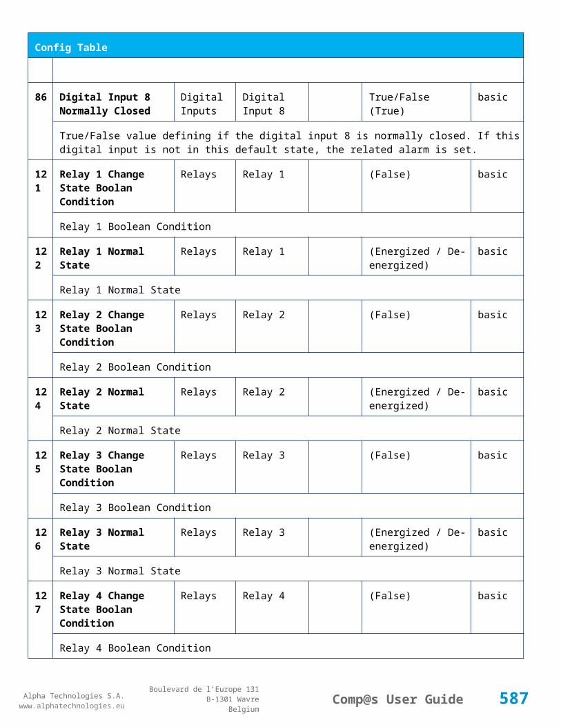
Alpha Technologies S.A.www.alphatechnologies.eu
Alpha Technologies S.A.www.alphatechnologies.eu
Comp@s User GuideBoulevard de l’Europe 131
B-1301 WavreBelgium
Config Table
24
Slot 4 Slots Slot 4 basic
25
Slot 5 Slots Slot 5 basic
26
Slot 6 Slots Slot 6 basic
27
Slot 7 Slots Slot 7 basic
28
Slot 8 Slots Slot 8 basic
29
Slot 9 Slots Slot 9 basic
30
Slot 10 Slots Slot 10 basic
31
Slot 11 Slots Slot 11 basic
32
Slot 12 Slots Slot 12 basic
33
Slot 13 Slots Slot 13 basic
34
Slot 14 Slots Slot 14 basic
35
Slot 15 Slots Slot 15 basic
36
Slot 16 Slots Slot 16 basic
51
Urgent Relay Energized Boolean Condition
Relays
basic
587

Alpha Technologies S.A.www.alphatechnologies.eu
Alpha Technologies S.A.www.alphatechnologies.eu
Comp@s User GuideBoulevard de l’Europe 131
B-1301 WavreBelgium
Config Table
52
Non Urgent Relay Energized Boolean Condition
Relays
basic
Control Table
Id Name Group SubGroup License
501
Clear My Events Generic Events basic
By writing '1' to this control element, all the events of this equipment will be cleared.
502
Clear All Events Generic Events basic
By writing '1' to this control element, all the events of this equipment and all the events of all the sub-equipments will be cleared.
511
Add Event Generic Events basic
This control element adds an event of severity none. The event name is the text written to this control element
512
Add Major Event Generic Events basic
This control element adds an event of severity major. The event name is the text written to this control element
521
Reset Default Names And Groups Generic Renaming basic
This control element resets all the element Names, Groups and Subgroups to default values for this equipment
522
Reset Default Names And Groups Recursive Generic Renaming basic
This control element resets all the element Names, Groups and Subgroups to default values for this equipment and all sub equipments
7.7 Remote Site Tables
7.7.1 CEM03_Remote_Site
Device Information
Name CEM03_Remote_Site
588

Alpha Technologies S.A.www.alphatechnologies.eu
Alpha Technologies S.A.www.alphatechnologies.eu
Comp@s User GuideBoulevard de l’Europe 131
B-1301 WavreBelgium
Device Information
Short Description Monitoring for Central Up Converter system
Long Description Central monitoring card for 4 down converter cards with CAN IN/CAN OUT and 4 relays
Hardware Reference
9413 044 89421
Software Reference SOFT 000022 XX
Equipment Type Monitoring For Remote (About Remote Site)
ETSI Level /site/energy_system/remote_power_feeding_system/remote_site
Description Table
Id Name Group License
2 Site Name Site basic
The name of the site
3 Short Description Site basic
A short description of the site
4 Info Site basic
Some more information about the site
11 Street Address basic
Street part of the site address
12 City Address basic
City part of the site address
13 Province Address basic
Province part of the site address
14 Postal Code Address basic
Postal Code part of the site address
15 Region Address basic
Region part of the site address
16 Country Address basic
589

Alpha Technologies S.A.www.alphatechnologies.eu
Alpha Technologies S.A.www.alphatechnologies.eu
Comp@s User GuideBoulevard de l’Europe 131
B-1301 WavreBelgium
Description Table
Country part of the site address
31 Latitude GPS Position asset
The latitude of the site
32 Longitude GPS Position asset
The longitude of the site
33 Altitude GPS Position asset
The altitude of the site
Alarm Table
Id Name Severity Type (Level) Set/Clear Delay
1 One Down Converter Failure minor (4) 10 / 2
2 More Than One Down Converter Failure major (6) 10 / 2
3 One Fan Failure minor (4) 30 / 2
4 More Than One FAN Failure major (6) 30 / 2
5 Possible Power Feed Reduced warning (2) 5 / 2
8 One Down Converter Over Temperature minor (4) 10 / 2
9 Output 1 Off major (6) 5 / 2
10 Output 2 Off major (6) 5 / 2
15 Communication Failure major (6) 5 / 2
590

Alpha Technologies S.A.www.alphatechnologies.eu
Alpha Technologies S.A.www.alphatechnologies.eu
Comp@s User GuideBoulevard de l’Europe 131
B-1301 WavreBelgium
Alarm Table
25 Digital Input 1 major (6) 5 / 2
This alarm is related to digital input 1
26 Digital Input 2 major (6) 5 / 2
This alarm is related to digital input 2
27 Digital Input 3 major (6) 5 / 2
This alarm is related to digital input 3
28 Digital Input 4 minor (4) 5 / 2
This alarm is related to digital input 4
29 Digital Input 5 minor (4) 5 / 2
This alarm is related to digital input 5
30 Digital Input 6 minor (4) 5 / 2
This alarm is related to digital input 6
Data Table
Id Name Group Unit License
1 Number of Configured Power Lines Lines basic
No information
2 Line Configured for Monitoring Lines basic
No information
11 Remote Type Remote DC System basic
No information
12 Input Voltage Remote DC System Volt basic
No information
13 Input Common Mode Voltage Remote DC System Volt basic
Input Common Mode Voltage with respect to ground
14 Output Voltage Remote DC System Volt basic
591

Alpha Technologies S.A.www.alphatechnologies.eu
Alpha Technologies S.A.www.alphatechnologies.eu
Comp@s User GuideBoulevard de l’Europe 131
B-1301 WavreBelgium
Data Table
No information
15 Temperature Remote DC System degree C basic
No information
21 Number Of Declared Down Converters Remote DC System basic
No information
Config Table
Id Name Group Unit Range: Min/Max (default) License
91 Digital Input 1 Name Digital Inputs Digital Input 1 basic
The name of the digital input 1
93 Digital Input 2 Name Digital Inputs Digital Input 2 basic
The name of the digital input 2
95 Digital Input 3 Name Digital Inputs Digital Input 3 basic
The name of the digital input 3
97 Digital Input 4 Name Digital Inputs Digital Input 4 basic
The name of the digital input 4
99 Digital Input 5 Name Digital Inputs Digital Input 5 basic
The name of the digital input 5
101 Digital Input 6 Name Digital Inputs Digital Input 6 basic
The name of the digital input 6
Control Table
Id Name Group License
11 Copy Address From Top Site Level Address basic
Writing a '1' to this control element will copy the Address from the Site level, except the Street Name
501
Clear My Events Event basic
By writing '1' to this control element, all the events of this equipment will be cleared.
50 Clear All Events Event basic
592

Alpha Technologies S.A.www.alphatechnologies.eu
Alpha Technologies S.A.www.alphatechnologies.eu
Comp@s User GuideBoulevard de l’Europe 131
B-1301 WavreBelgium
Control Table
2
By writing '1' to this control element, all the events of this equipment and all the events of all the sub-equipments will be cleared.
511
Add Event Event basic
This control element adds an event of severity none. The event name is the text written to this control element
512
Add Major Event Event basic
This control element adds an event of severity major. The event name is the text written to this control element
521
Reset Default Names And Groups Advanced basic
This control element resets all the element Names, Groups and Subgroups to default values for this equipment
522
Reset Default Names And Groups Recursive Advanced basic
This control element resets all the element Names, Groups and Subgroups to default values for this equipment and all sub equipments
7.7.2 CEM03 Remote Site
Device Information
Name CEM03 Remote Site
Short Description Monitoring for Central Up Converter system
Long Description Central monitoring card for 4 down converter cards with CAN IN/CAN OUT and 4 relays
Hardware Reference
9413 044 89421
Software Reference SOFT 000022 XX
Equipment Type Monitoring For Remote (About Remote Site)
ETSI Level /site/energy_system/remote_power_feeding_system/remote_site
Description Table
Id Name Group SubGroup License
2 Site Name Site basic
593

Alpha Technologies S.A.www.alphatechnologies.eu
Alpha Technologies S.A.www.alphatechnologies.eu
Comp@s User GuideBoulevard de l’Europe 131
B-1301 WavreBelgium
Description Table
The name of the site
3 Short Description Site basic
A short description of the site
4 Info Site basic
Some more information about the site
11 Street Address basic
Street part of the site address
12 City Address basic
City part of the site address
13 Province Address basic
Province part of the site address
14 Postal Code Address basic
Postal Code part of the site address
15 Region Address basic
Region part of the site address
16 Country Address basic
Country part of the site address
31 Latitude GPS Position asset
The latitude of the site
32 Longitude GPS Position asset
The longitude of the site
33 Altitude GPS Position asset
The altitude of the site
Alarm Table
Id Name Group SubGroup Severity Type (Level)
Set/Clear Delay
1 One Down Converter Failure Converters minor (4) 10 / 2
594

Alpha Technologies S.A.www.alphatechnologies.eu
Alpha Technologies S.A.www.alphatechnologies.eu
Comp@s User GuideBoulevard de l’Europe 131
B-1301 WavreBelgium
Alarm Table
2 More Than One Down Converter Failure
Converters major (6) 10 / 2
3 One Fan Failure Converters minor (4) 30 / 2
4 More Than One FAN Failure Converters major (6) 30 / 2
5 Possible Power Feed Reduced Converters warning (2) 5 / 2
8 One Down Converter Over Temperature
Converters minor (4) 10 / 2
9 Output 1 Off Outputs major (6) 5 / 2
10
Output 2 Off Outputs major (6) 5 / 2
15
Communication Failure Communication
major (6) 5 / 2
25
Digital Input 1 Digital Inputs Digital Input 1
major (0) 5 / 2
This alarm is related to digital input 1
26
Digital Input 2 Digital Inputs Digital Input 2
major (0) 5 / 2
This alarm is related to digital input 2
27
Digital Input 3 Digital Inputs Digital Input 3
major (0) 5 / 2
This alarm is related to digital input 3
28
Digital Input 4 Digital Inputs Digital Input 4
minor (0) 5 / 2
595
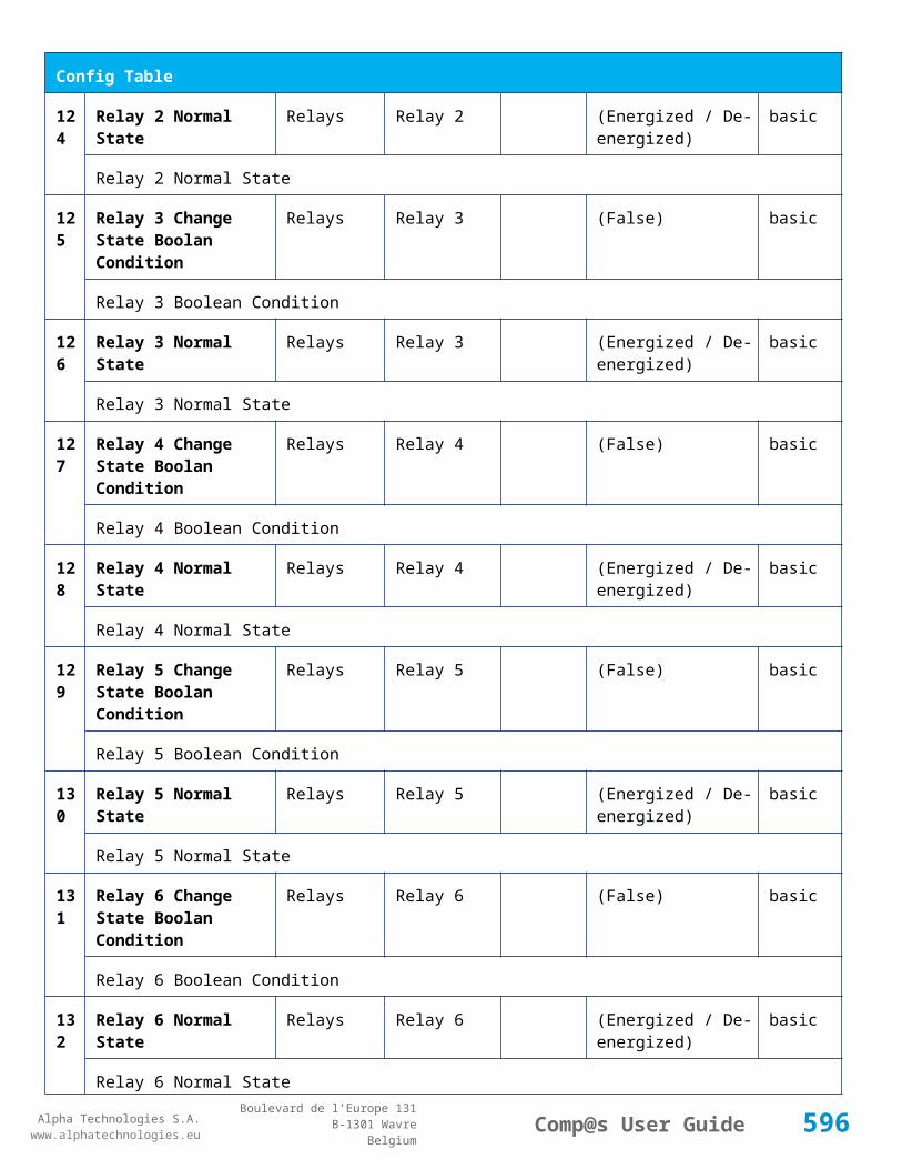
Alpha Technologies S.A.www.alphatechnologies.eu
Alpha Technologies S.A.www.alphatechnologies.eu
Comp@s User GuideBoulevard de l’Europe 131
B-1301 WavreBelgium
Alarm Table
This alarm is related to digital input 4
29
Digital Input 5 Digital Inputs Digital Input 5
minor (0) 5 / 2
This alarm is related to digital input 5
30
Digital Input 6 Digital Inputs Digital Input 6
minor (0) 5 / 2
This alarm is related to digital input 6
Data Table
Id Name Group SubGroup Unit License
1 Number of Configured Power Lines Lines basic
2 Line Configured for Monitoring Lines basic
11 Remote Type Remote DC System basic
12 Input Voltage Remote DC System Volt basic
13 Input Common Mode Voltage Remote DC System Volt basic
Input Common Mode Voltage with respect to ground
14 Output Voltage Remote DC System Volt basic
15 Temperature Remote DC System degree C basic
21 Number Of Declared Down Converters Remote DC System basic
Config Table
Id Name Group SubGroup Unit Range: Min/Max (default) License
596
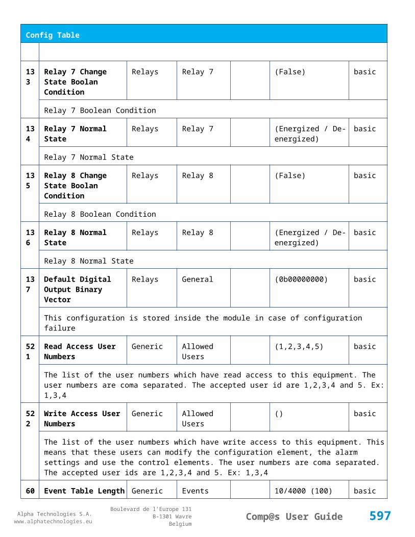
Alpha Technologies S.A.www.alphatechnologies.eu
Alpha Technologies S.A.www.alphatechnologies.eu
Comp@s User GuideBoulevard de l’Europe 131
B-1301 WavreBelgium
Config Table
91 Digital Input 1 Name Digital Inputs Digital Input 1 Digital Input 1 basic
The name of the digital input 1
93 Digital Input 2 Name Digital Inputs Digital Input 2 Digital Input 2 basic
The name of the digital input 2
95 Digital Input 3 Name Digital Inputs Digital Input 3 Digital Input 3 basic
The name of the digital input 3
97 Digital Input 4 Name Digital Inputs Digital Input 4 Digital Input 4 basic
The name of the digital input 4
99 Digital Input 5 Name Digital Inputs Digital Input 5 Digital Input 5 basic
The name of the digital input 5
101 Digital Input 6 Name Digital Inputs Digital Input 6 Digital Input 6 basic
The name of the digital input 6
Control Table
Id Name Group SubGroup License
11 Copy Address From Top Site Level Address basic
Writing a '1' to this control element will copy the Address from the Site level, except the Street Name
501
Clear My Events Generic Events basic
By writing '1' to this control element, all the events of this equipment will be cleared.
502
Clear All Events Generic Events basic
By writing '1' to this control element, all the events of this equipment and all the events of all the sub-equipments will be cleared.
511
Add Event Generic Events basic
This control element adds an event of severity none. The event name is the text written to this control element
512
Add Major Event Generic Events basic
This control element adds an event of severity major. The event name is the text written to this control element
597

Alpha Technologies S.A.www.alphatechnologies.eu
Alpha Technologies S.A.www.alphatechnologies.eu
Comp@s User GuideBoulevard de l’Europe 131
B-1301 WavreBelgium
Control Table
521
Reset Default Names And Groups Generic Renaming basic
This control element resets all the element Names, Groups and Subgroups to default values for this equipment
522
Reset Default Names And Groups Recursive Generic Renaming basic
This control element resets all the element Names, Groups and Subgroups to default values for this equipment and all sub equipments
7.8 Inverter Tables
7.8.1 Inverter Module (T2S)
Device Information
Name Inverter Module (T2S)
Short Description Inverter (Bravo, Media, Nova, etc.), managed by T2S
Long Description
Hardware Reference
Software Reference
Equipment Type Missing information
ETSI Level /site/energy_system/inverter_system/inverter
Description Table
Id Name Group SubGroup License
5 Serial Number Product Info basic
Serial Number
6 Version Product Info basic
Software Revision
11 Module Number Live Configuration basic
Module Address
21 AC Output Group Live Configuration basic
598

Alpha Technologies S.A.www.alphatechnologies.eu
Alpha Technologies S.A.www.alphatechnologies.eu
Comp@s User GuideBoulevard de l’Europe 131
B-1301 WavreBelgium
Description Table
Inverter module AC output group
22 AC Input Group Live Configuration basic
Inverter module AC input group
23 DC Input Group Live Configuration basic
Inverter module DC input group
Alarm Table
Id Name Group SubGroup Severity Type (Level) Set/Clear Delay
34 Temp Too High General major (6) 5 / 2
Temperature on heat sink to high
83 Manually Off General minor (4) 5 / 2
The inverter are seted in manually OFF.
101 Fan Failure General major (6) 5 / 2
Failed fan or speed inapropriate
161 Vac In Too Low AC IN minor (4) 5 / 2
162 Vac In Too High AC IN minor (4) 5 / 2
194 Vdc In Too Low DC IN minor (4) 5 / 2
195 Vdc In Too High DC IN minor (4) 5 / 2
255 Specific Alarm major (6) 5 / 2
Specific manufacturer alarm. Please contact your reseller
Data Table
Id Name Group SubGroup Unit License
599
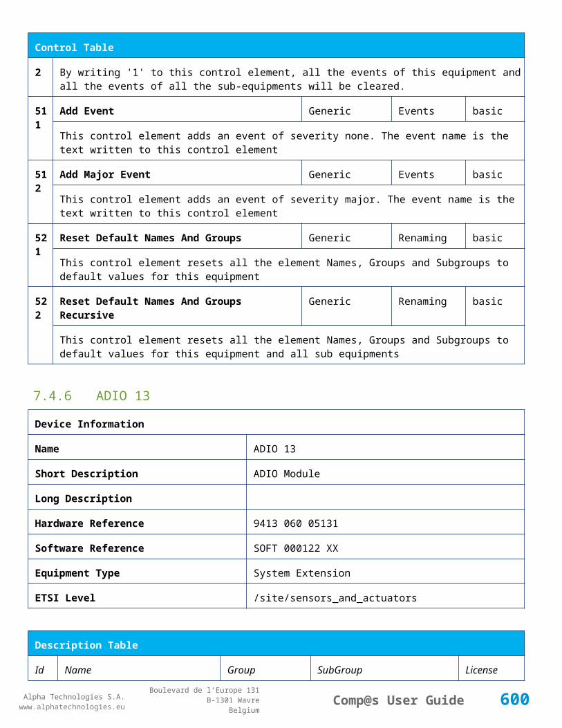
Alpha Technologies S.A.www.alphatechnologies.eu
Alpha Technologies S.A.www.alphatechnologies.eu
Comp@s User GuideBoulevard de l’Europe 131
B-1301 WavreBelgium
Data Table
1 Module Status Inverter Status basic
Module Status
2 AC Output Status Inverter Status basic
Module AC output status
3 AC Input Status Inverter Status basic
Module AC input status
4 DC Input Status Inverter Status basic
Module DC input status
5 Temperature Inverter Status degree C basic
Temperature
11 Output Voltage AC Output Volt basic
Output voltage in volts
12 Output Current AC Output Ampere basic
Output current in amperes
13 Output Power AC Output Watt basic
Output power in watts
14 Output Apparent Power AC Output VA basic
Output apparent power in VA
16 Load Position regarding input power source AC Output basic
Position of the load regarding input power sources
17 Loading Ratio in W AC Output % basic
Loading ratio regarding power un watts
18 Loading Ratio in VA AC Output % basic
Loading ratio regarding power un watts
21 Input Voltage AC Input Volt basic
AC input voltage
22 Input Current AC Input Ampere basic
600

Alpha Technologies S.A.www.alphatechnologies.eu
Alpha Technologies S.A.www.alphatechnologies.eu
Comp@s User GuideBoulevard de l’Europe 131
B-1301 WavreBelgium
Data Table
AC input current
23 Input Power AC Input Watt basic
AC input power in watts
24 Input Apparent Power AC Input VA basic
AC apparent input power in VA
25 Input Frequency AC Input Hz basic
AC Input Frequency
31 Input Voltage DC Input Volt basic
DC input voltage
32 Input Current DC Input Ampere basic
DC input current
33 Input Power DC Input Watt basic
DC input power
101 Specific Id Alarms Error List basic
List of active manufacturer specific alarms
102 Alarm Name List Error List basic
List of active manufacturer specific alarms
Control Table
Id Name Group SubGroup License
1 Start Locate Inverter TSI Inverter basic
Locate the inverter module.
11 Turn On Module TSI Inverter basic
Turn on the inverter module.
12 Turn Off Module TSI Inverter basic
Turn off the inverter module.
21 Modify AC Input Group TSI Inverter basic
601

Alpha Technologies S.A.www.alphatechnologies.eu
Alpha Technologies S.A.www.alphatechnologies.eu
Comp@s User GuideBoulevard de l’Europe 131
B-1301 WavreBelgium
Control Table
Modify ...
22 Modify DC Input Group TSI Inverter basic
Modify ...
23 Modify AC Output Group TSI Inverter basic
Modify ...
31 Modify Inverter Id TSI Inverter basic
Modify ...
7.9 Inverter System Tables
7.9.1 Inverter System (T2S)
Device Information
Name Inverter System (T2S)
Short Description Inverter System (With Bravo, Media, Nova, etc. ), managed by T2S
Long Description
Hardware Reference
Software Reference
Equipment Type Missing information
ETSI Level /site/energy_system/inverter_system
Description Table
Id Name Group SubGroup License
1 Description Description Custom Description basic
A free text zone to write a system description
2 Reference Description Custom Description basic
A free text zone to write the customer reference of the system
10 T2S Serial Number Description T2S basic
602

Alpha Technologies S.A.www.alphatechnologies.eu
Alpha Technologies S.A.www.alphatechnologies.eu
Comp@s User GuideBoulevard de l’Europe 131
B-1301 WavreBelgium
Description Table
T2S Serial Number
11 T2S Software Revision Description T2S basic
T2S Software Revision
Alarm Table
Id Name Group SubGroup
Severity Type (Level)
Set/Clear Delay
1 One Inverter in Alarm Inverter System
minor (4) 5 / 2
One Inverter is in alarm. Check specific Inverter Alarm table.
2 More Than One Inverter in Alarm
Inverter System
major (6) 10 / 2
More than one Inverter are in alarm
161
Vac In Too Low AC Inputs minor (4) 5 / 2
162
Vac In Too High AC Inputs minor (4) 5 / 2
194
Vdc In Too Low DC Inputs minor (4) 5 / 2
195
Vdc In Too High DC Inputs minor (4) 5 / 2
227
Digital Input 1 Failure Digital Inputs major (6) 5 / 2
Give alarm with code 227 and appropriate texte when digital input 1 change is state
228
Digital Input 2 Failure Digital Inputs major (6) 5 / 2
Give alarm with code 228 and appropriate text when digital input 2 change is state
229
Redundancy Lost Inverter System
minor (4) 5 / 2
Give alarm with code 229 and text 'Redudancy Lost' when the condition is true
230
Redundancy Plus 1 Lost Inverter System
major (6) 5 / 2
603

Alpha Technologies S.A.www.alphatechnologies.eu
Alpha Technologies S.A.www.alphatechnologies.eu
Comp@s User GuideBoulevard de l’Europe 131
B-1301 WavreBelgium
Alarm Table
Give alarm with code 230 and text 'Redudancy + 1 Lost' when the condition is true
232
Main Source Lost AC Inputs major (6) 5 / 2
Give alarm with code 232 and text 'Mains source lost' when the condition is true
233
Secondary Source Lost DC Inputs minor (4) 5 / 2
Give alarm with code 233 and 'Sec Source Lost' when the condition is true
235
T2S Failure Inverter System
major (6) 5 / 2
Give alarm with code 235 and text 'T2S FAILURE' when the condition is true
255
Specific Alarm major (6) 5 / 2
Specific manufacturer alarm. Please contact your reseller
Data Table
Id Name Group SubGroup Unit License
1 Output Voltage AC Outputs AC Output 1 Volt basic
Output Voltage in volts group 1
2 Output Power AC Outputs AC Output 1 Ampere basic
Output Current in amperes group 1
3 Output Power AC Outputs AC Output 1 Watt basic
Output power in watts group 1
4 Output Apparent Power AC Outputs AC Output 1 VA basic
Output apparent power in VA group 1
5 Output Frequency AC Outputs AC Output 1 Hz basic
Output Frequency in hertz group 1
6 Loading Ratio AC Outputs AC Output 1 % basic
Ratio between output load and available power expressed in watts group 1
7 Loading Ratio - Available Power in VA AC Outputs AC Output 1 % basic
Ratio between output load and available power expressed in VA group 1
8 Loading Ratio - Installed Power in W AC Outputs AC Output 1 % basic
604

Alpha Technologies S.A.www.alphatechnologies.eu
Alpha Technologies S.A.www.alphatechnologies.eu
Comp@s User GuideBoulevard de l’Europe 131
B-1301 WavreBelgium
Data Table
Ratio between output load and installed power expressed in watts group 1
9 Loading Ratio - Installed Power in VA AC Outputs AC Output 1 % basic
Ratio between output load and installed power expressed in VA group 1
10 Number Of Modules Configured AC Outputs AC Output 1 basic
Number of modules configured for the phase 1
11 Amount of redundancy configured AC Outputs AC Output 1 basic
Amount of redundancy configured in the phase 1
12 DC Input Power AC Outputs AC Output 1 Watt basic
DC input power for group 1
13 AC Input Power in W AC Outputs AC Output 1 Watt basic
AC input power (W) for group 1
14 AC Input Power in VA AC Outputs AC Output 1 VA basic
AC input power (VA) for group 1
15 Installed Power in W AC Outputs AC Output 1 Watt basic
Installed power value in watts for group 1
16 Installed Power in VA AC Outputs AC Output 1 VA basic
Installed power value in VA for group 1
17 Available Power in W AC Outputs AC Output 1 Watt basic
Available power value in watts for group 1
18 Available Power in VA AC Outputs AC Output 1 VA basic
Available power value in VA for group 1
19 Number Of Module seen by T2S AC Outputs AC Output 1 basic
Number of modules seen by T2S for group 1
20 Number Of Modules delivering output AC Outputs AC Output 1 basic
Number of modules delivering output for group 1
21 Number Of Modules manually off AC Outputs AC Output 1 basic
Number of modules manually off for group 1
605

Alpha Technologies S.A.www.alphatechnologies.eu
Alpha Technologies S.A.www.alphatechnologies.eu
Comp@s User GuideBoulevard de l’Europe 131
B-1301 WavreBelgium
Data Table
22 Number Of Module In Failure AC Outputs AC Output 1 basic
Number of modules in failure for group 1
23 Number Of Module not seen by T2S AC Outputs AC Output 1 basic
Number of modules not seen by T2S for group 1
51 Output Voltage AC Outputs AC Output 2 Volt basic
Output Voltage in volts group 2
52 Output Power AC Outputs AC Output 2 Ampere basic
Output Current in amperes group 2
53 Output Power AC Outputs AC Output 2 Watt basic
Output power in watts group 2
54 Output Apparent Power AC Outputs AC Output 2 VA basic
Output apparent power in VA group 2
55 Output Frequency AC Outputs AC Output 2 Hz basic
Output Frequency in hertz group 2
56 Loading Ratio AC Outputs AC Output 2 % basic
Ratio between output load and available power expressed in watts group 2
57 Loading Ratio - Available Power in VA AC Outputs AC Output 2 % basic
Ratio between output load and available power expressed in VA group 2
58 Loading Ratio - Installed Power in W AC Outputs AC Output 2 % basic
Ratio between output load and installed power expressed in watts group 2
59 Loading Ratio - Installed Power in VA AC Outputs AC Output 2 % basic
Ratio between output load and installed power expressed in VA group 2
60 Number Of Modules Configured AC Outputs AC Output 2 basic
Number of modules configured for the phase 2
61 Amount of redundancy configured AC Outputs AC Output 2 basic
Amount of redundancy configured in the phase 2
62 DC Input Power AC Outputs AC Output 2 Watt basic
606

Alpha Technologies S.A.www.alphatechnologies.eu
Alpha Technologies S.A.www.alphatechnologies.eu
Comp@s User GuideBoulevard de l’Europe 131
B-1301 WavreBelgium
Data Table
DC input power for group 2
63 AC Input Power in W AC Outputs AC Output 2 Watt basic
AC input power (W) for group 2
64 AC Input Power in VA AC Outputs AC Output 2 VA basic
AC input power (VA) for group 2
65 Installed Power in W AC Outputs AC Output 2 Watt basic
Installed power value in watts for group 2
66 Installed Power in VA AC Outputs AC Output 2 VA basic
Installed power value in VA for group 2
67 Available Power in W AC Outputs AC Output 2 Watt basic
Available power value in watts for group 2
68 Available Power in VA AC Outputs AC Output 2 VA basic
Available power value in VA for group 2
69 Number Of Module seen by T2S AC Outputs AC Output 2 basic
Number of modules seen by T2S for group 2
70 Number Of Modules delivering output AC Outputs AC Output 2 basic
Number of modules delivering output for group 2
71 Number Of Modules manually off AC Outputs AC Output 2 basic
Number of modules manually off for group 2
72 Number Of Module In Failure AC Outputs AC Output 2 basic
Number of modules in failure for group 2
73 Number Of Module not seen by T2S AC Outputs AC Output 2 basic
Number of modules not seen by T2S for group 2
101 Output Voltage AC Outputs AC Output 3 Volt basic
Output Voltage in volts group 3
102 Output Power AC Outputs AC Output 3 Ampere basic
Output Current in amperes group 3
607

Alpha Technologies S.A.www.alphatechnologies.eu
Alpha Technologies S.A.www.alphatechnologies.eu
Comp@s User GuideBoulevard de l’Europe 131
B-1301 WavreBelgium
Data Table
103 Output Power AC Outputs AC Output 3 Watt basic
Output power in watts group 3
104 Output Apparent Power AC Outputs AC Output 3 VA basic
Output apparent power in VA group 3
105 Output Frequency AC Outputs AC Output 3 Hz basic
Output Frequency in hertz group 3
106 Loading Ratio AC Outputs AC Output 3 % basic
Ratio between output load and available power expressed in watts group 3
107 Loading Ratio - Available Power in VA AC Outputs AC Output 3 % basic
Ratio between output load and available power expressed in VA group 3
108 Loading Ratio - Installed Power in W AC Outputs AC Output 3 % basic
Ratio between output load and installed power expressed in watts group 3
109 Loading Ratio - Installed Power in VA AC Outputs AC Output 3 % basic
Ratio between output load and installed power expressed in VA group 3
110 Number Of Modules Configured AC Outputs AC Output 3 basic
Number of modules configured for the phase 3
111 Amount of redundancy configured AC Outputs AC Output 3 basic
Amount of redundancy configured in the phase 3
112 DC Input Power AC Outputs AC Output 3 Watt basic
DC input power for group 3
113 AC Input Power in W AC Outputs AC Output 3 Watt basic
AC input power (W) for group 3
114 AC Input Power in VA AC Outputs AC Output 3 VA basic
AC input power (VA) for group 3
115 Installed Power in W AC Outputs AC Output 3 Watt basic
Installed power value in watts for group 3
116 Installed Power in VA AC Outputs AC Output 3 VA basic
608
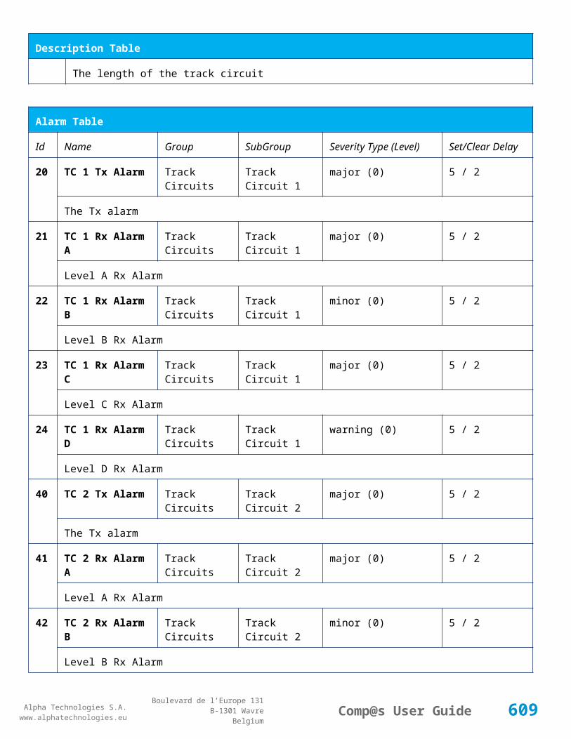
Alpha Technologies S.A.www.alphatechnologies.eu
Alpha Technologies S.A.www.alphatechnologies.eu
Comp@s User GuideBoulevard de l’Europe 131
B-1301 WavreBelgium
Data Table
Installed power value in VA for group 3
117 Available Power in W AC Outputs AC Output 3 Watt basic
Available power value in watts for group 3
118 Available Power in VA AC Outputs AC Output 3 VA basic
Available power value in VA for group 3
119 Number Of Module seen by T2S AC Outputs AC Output 3 basic
Number of modules seen by T2S for group 3
120 Number Of Modules delivering output AC Outputs AC Output 3 basic
Number of modules delivering output for group 3
121 Number Of Modules manually off AC Outputs AC Output 3 basic
Number of modules manually off for group 3
122 Number Of Module In Failure AC Outputs AC Output 3 basic
Number of modules in failure for group 3
123 Number Of Module not seen by T2S AC Outputs AC Output 3 basic
Number of modules not seen by T2S for group 3
151 Output Voltage AC Outputs AC Output 4 Volt basic
Output Voltage in volts group 4
152 Output Power AC Outputs AC Output 4 Ampere basic
Output Current in amperes group 4
153 Output Power AC Outputs AC Output 4 Watt basic
Output power in watts group 4
154 Output Apparent Power AC Outputs AC Output 4 VA basic
Output apparent power in VA group 4
155 Output Frequency AC Outputs AC Output 4 Hz basic
Output Frequency in hertz group 4
156 Loading Ratio AC Outputs AC Output 4 % basic
Ratio between output load and available power expressed in watts group 4
609

Alpha Technologies S.A.www.alphatechnologies.eu
Alpha Technologies S.A.www.alphatechnologies.eu
Comp@s User GuideBoulevard de l’Europe 131
B-1301 WavreBelgium
Data Table
157 Loading Ratio - Available Power in VA AC Outputs AC Output 4 % basic
Ratio between output load and available power expressed in VA group 4
158 Loading Ratio - Installed Power in W AC Outputs AC Output 4 % basic
Ratio between output load and installed power expressed in watts group 4
159 Loading Ratio - Installed Power in VA AC Outputs AC Output 4 % basic
Ratio between output load and installed power expressed in VA group 4
160 Number Of Modules Configured AC Outputs AC Output 4 basic
Number of modules configured for the phase 4
161 Amount of redundancy configured AC Outputs AC Output 4 basic
Amount of redundancy configured in the phase 4
162 DC Input Power AC Outputs AC Output 4 Watt basic
DC input power for group 4
163 AC Input Power in W AC Outputs AC Output 4 Watt basic
AC input power (W) for group 4
164 AC Input Power in VA AC Outputs AC Output 4 VA basic
AC input power (VA) for group 4
165 Installed Power in W AC Outputs AC Output 4 Watt basic
Installed power value in watts for group 4
166 Installed Power in VA AC Outputs AC Output 4 VA basic
Installed power value in VA for group 4
167 Available Power in W AC Outputs AC Output 4 Watt basic
Available power value in watts for group 4
168 Available Power in VA AC Outputs AC Output 4 VA basic
Available power value in VA for group 4
169 Number Of Module seen by T2S AC Outputs AC Output 4 basic
Number of modules seen by T2S for group 4
170 Number Of Modules delivering output AC Outputs AC Output 4 basic
610

Alpha Technologies S.A.www.alphatechnologies.eu
Alpha Technologies S.A.www.alphatechnologies.eu
Comp@s User GuideBoulevard de l’Europe 131
B-1301 WavreBelgium
Data Table
Number of modules delivering output for group 4
171 Number Of Modules manually off AC Outputs AC Output 4 basic
Number of modules manually off for group 4
172 Number Of Module In Failure AC Outputs AC Output 4 basic
Number of modules in failure for group 4
173 Number Of Module not seen by T2S AC Outputs AC Output 4 basic
Number of modules not seen by T2S for group 4
201 Output Voltage AC Outputs AC Output 5 Volt basic
Output Voltage in volts group 5
202 Output Power AC Outputs AC Output 5 Ampere basic
Output Current in amperes group 5
203 Output Power AC Outputs AC Output 5 Watt basic
Output power in watts group 5
204 Output Apparent Power AC Outputs AC Output 5 VA basic
Output apparent power in VA group 5
205 Output Frequency AC Outputs AC Output 5 Hz basic
Output Frequency in hertz group 5
206 Loading Ratio AC Outputs AC Output 5 % basic
Ratio between output load and available power expressed in watts group 5
207 Loading Ratio - Available Power in VA AC Outputs AC Output 5 % basic
Ratio between output load and available power expressed in VA group 5
208 Loading Ratio - Installed Power in W AC Outputs AC Output 5 % basic
Ratio between output load and installed power expressed in watts group 5
209 Loading Ratio - Installed Power in VA AC Outputs AC Output 5 % basic
Ratio between output load and installed power expressed in VA group 5
210 Number Of Modules Configured AC Outputs AC Output 5 basic
Number of modules configured for the phase 5
611

Alpha Technologies S.A.www.alphatechnologies.eu
Alpha Technologies S.A.www.alphatechnologies.eu
Comp@s User GuideBoulevard de l’Europe 131
B-1301 WavreBelgium
Data Table
211 Amount of redundancy configured AC Outputs AC Output 5 basic
Amount of redundancy configured in the phase 5
212 DC Input Power AC Outputs AC Output 5 Watt basic
DC input power for group 5
213 AC Input Power in W AC Outputs AC Output 5 Watt basic
AC input power (W) for group 5
214 AC Input Power in VA AC Outputs AC Output 5 VA basic
AC input power (VA) for group 5
215 Installed Power in W AC Outputs AC Output 5 Watt basic
Installed power value in watts for group 5
216 Installed Power in VA AC Outputs AC Output 5 VA basic
Installed power value in VA for group 5
217 Available Power in W AC Outputs AC Output 5 Watt basic
Available power value in watts for group 5
218 Available Power in VA AC Outputs AC Output 5 VA basic
Available power value in VA for group 5
219 Number Of Module seen by T2S AC Outputs AC Output 5 basic
Number of modules seen by T2S for group 5
220 Number Of Modules delivering output AC Outputs AC Output 5 basic
Number of modules delivering output for group 5
221 Number Of Modules manually off AC Outputs AC Output 5 basic
Number of modules manually off for group 5
222 Number Of Module In Failure AC Outputs AC Output 5 basic
Number of modules in failure for group 5
223 Number Of Module not seen by T2S AC Outputs AC Output 5 basic
Number of modules not seen by T2S for group 5
251 Output Voltage AC Outputs AC Output 6 Volt basic
612

Alpha Technologies S.A.www.alphatechnologies.eu
Alpha Technologies S.A.www.alphatechnologies.eu
Comp@s User GuideBoulevard de l’Europe 131
B-1301 WavreBelgium
Data Table
Output Voltage in volts group 6
252 Output Power AC Outputs AC Output 6 Ampere basic
Output Current in amperes group 6
253 Output Power AC Outputs AC Output 6 Watt basic
Output power in watts group 6
254 Output Apparent Power AC Outputs AC Output 6 VA basic
Output apparent power in VA group 6
255 Output Frequency AC Outputs AC Output 6 Hz basic
Output Frequency in hertz group 6
256 Loading Ratio AC Outputs AC Output 6 % basic
Ratio between output load and available power expressed in watts group 6
257 Loading Ratio - Available Power in VA AC Outputs AC Output 6 % basic
Ratio between output load and available power expressed in VA group 6
258 Loading Ratio - Installed Power in W AC Outputs AC Output 6 % basic
Ratio between output load and installed power expressed in watts group 6
259 Loading Ratio - Installed Power in VA AC Outputs AC Output 6 % basic
Ratio between output load and installed power expressed in VA group 6
260 Number Of Modules Configured AC Outputs AC Output 6 basic
Number of modules configured for the phase 6
261 Amount of redundancy configured AC Outputs AC Output 6 basic
Amount of redundancy configured in the phase 6
262 DC Input Power AC Outputs AC Output 6 Watt basic
DC input power for group 6
263 AC Input Power in W AC Outputs AC Output 6 Watt basic
AC input power (W) for group 6
264 AC Input Power in VA AC Outputs AC Output 6 VA basic
AC input power (VA) for group 6
613
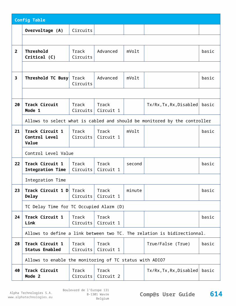
Alpha Technologies S.A.www.alphatechnologies.eu
Alpha Technologies S.A.www.alphatechnologies.eu
Comp@s User GuideBoulevard de l’Europe 131
B-1301 WavreBelgium
Data Table
265 Installed Power in W AC Outputs AC Output 6 Watt basic
Installed power value in watts for group 6
266 Installed Power in VA AC Outputs AC Output 6 VA basic
Installed power value in VA for group 6
267 Available Power in W AC Outputs AC Output 6 Watt basic
Available power value in watts for group 6
268 Available Power in VA AC Outputs AC Output 6 VA basic
Available power value in VA for group 6
269 Number Of Module seen by T2S AC Outputs AC Output 6 basic
Number of modules seen by T2S for group 6
270 Number Of Modules delivering output AC Outputs AC Output 6 basic
Number of modules delivering output for group 6
271 Number Of Modules manually off AC Outputs AC Output 6 basic
Number of modules manually off for group 6
272 Number Of Module In Failure AC Outputs AC Output 6 basic
Number of modules in failure for group 6
273 Number Of Module not seen by T2S AC Outputs AC Output 6 basic
Number of modules not seen by T2S for group 6
301 Output Voltage AC Outputs AC Output 7 Volt basic
Output Voltage in volts group 7
302 Output Power AC Outputs AC Output 7 Ampere basic
Output Current in amperes group 7
303 Output Power AC Outputs AC Output 7 Watt basic
Output power in watts group 7
304 Output Apparent Power AC Outputs AC Output 7 VA basic
Output apparent power in VA group 7
305 Output Frequency AC Outputs AC Output 7 Hz basic
614

Alpha Technologies S.A.www.alphatechnologies.eu
Alpha Technologies S.A.www.alphatechnologies.eu
Comp@s User GuideBoulevard de l’Europe 131
B-1301 WavreBelgium
Data Table
Output Frequency in hertz group 7
306 Loading Ratio AC Outputs AC Output 7 % basic
Ratio between output load and available power expressed in watts group 7
307 Loading Ratio - Available Power in VA AC Outputs AC Output 7 % basic
Ratio between output load and available power expressed in VA group 7
308 Loading Ratio - Installed Power in W AC Outputs AC Output 7 % basic
Ratio between output load and installed power expressed in watts group 7
309 Loading Ratio - Installed Power in VA AC Outputs AC Output 7 % basic
Ratio between output load and installed power expressed in VA group 7
310 Number Of Modules Configured AC Outputs AC Output 7 basic
Number of modules configured for the phase 7
311 Amount of redundancy configured AC Outputs AC Output 7 basic
Amount of redundancy configured in the phase 7
312 DC Input Power AC Outputs AC Output 7 Watt basic
DC input power for group 7
313 AC Input Power in W AC Outputs AC Output 7 Watt basic
AC input power (W) for group 7
314 AC Input Power in VA AC Outputs AC Output 7 VA basic
AC input power (VA) for group 7
315 Installed Power in W AC Outputs AC Output 7 Watt basic
Installed power value in watts for group 7
316 Installed Power in VA AC Outputs AC Output 7 VA basic
Installed power value in VA for group 7
317 Available Power in W AC Outputs AC Output 7 Watt basic
Available power value in watts for group 7
318 Available Power in VA AC Outputs AC Output 7 VA basic
Available power value in VA for group 7
615

Alpha Technologies S.A.www.alphatechnologies.eu
Alpha Technologies S.A.www.alphatechnologies.eu
Comp@s User GuideBoulevard de l’Europe 131
B-1301 WavreBelgium
Data Table
319 Number Of Module seen by T2S AC Outputs AC Output 7 basic
Number of modules seen by T2S for group 7
320 Number Of Modules delivering output AC Outputs AC Output 7 basic
Number of modules delivering output for group 7
321 Number Of Modules manually off AC Outputs AC Output 7 basic
Number of modules manually off for group 7
322 Number Of Module In Failure AC Outputs AC Output 7 basic
Number of modules in failure for group 7
323 Number Of Module not seen by T2S AC Outputs AC Output 7 basic
Number of modules not seen by T2S for group 7
351 Output Voltage AC Outputs AC Output 8 Volt basic
Output Voltage in volts group 8
352 Output Power AC Outputs AC Output 8 Ampere basic
Output Current in amperes group 8
353 Output Power AC Outputs AC Output 8 Watt basic
Output power in watts group 8
354 Output Apparent Power AC Outputs AC Output 8 VA basic
Output apparent power in VA group 8
355 Output Frequency AC Outputs AC Output 8 Hz basic
Output Frequency in hertz group 8
356 Loading Ratio AC Outputs AC Output 8 % basic
Ratio between output load and available power expressed in watts group 8
357 Loading Ratio - Available Power in VA AC Outputs AC Output 8 % basic
Ratio between output load and available power expressed in VA group 8
358 Loading Ratio - Installed Power in W AC Outputs AC Output 8 % basic
Ratio between output load and installed power expressed in watts group 8
359 Loading Ratio - Installed Power in VA AC Outputs AC Output 8 % basic
616

Alpha Technologies S.A.www.alphatechnologies.eu
Alpha Technologies S.A.www.alphatechnologies.eu
Comp@s User GuideBoulevard de l’Europe 131
B-1301 WavreBelgium
Data Table
Ratio between output load and installed power expressed in VA group 8
360 Number Of Modules Configured AC Outputs AC Output 8 basic
Number of modules configured for the phase 8
361 Amount of redundancy configured AC Outputs AC Output 8 basic
Amount of redundancy configured in the phase 8
362 DC Input Power AC Outputs AC Output 8 Watt basic
DC input power for group 8
363 AC Input Power in W AC Outputs AC Output 8 Watt basic
AC input power (W) for group 8
364 AC Input Power in VA AC Outputs AC Output 8 VA basic
AC input power (VA) for group 8
365 Installed Power in W AC Outputs AC Output 8 Watt basic
Installed power value in watts for group 8
366 Installed Power in VA AC Outputs AC Output 8 VA basic
Installed power value in VA for group 8
367 Available Power in W AC Outputs AC Output 8 Watt basic
Available power value in watts for group 8
368 Available Power in VA AC Outputs AC Output 8 VA basic
Available power value in VA for group 8
369 Number Of Module seen by T2S AC Outputs AC Output 8 basic
Number of modules seen by T2S for group 8
370 Number Of Modules delivering output AC Outputs AC Output 8 basic
Number of modules delivering output for group 8
371 Number Of Modules manually off AC Outputs AC Output 8 basic
Number of modules manually off for group 8
372 Number Of Module In Failure AC Outputs AC Output 8 basic
Number of modules in failure for group 8
617

Alpha Technologies S.A.www.alphatechnologies.eu
Alpha Technologies S.A.www.alphatechnologies.eu
Comp@s User GuideBoulevard de l’Europe 131
B-1301 WavreBelgium
Data Table
373 Number Of Module not seen by T2S AC Outputs AC Output 8 basic
Number of modules not seen by T2S for group 8
401 Input Voltage AC Inputs AC Input 1 Volt basic
AC input voltage value (V) group 1
402 Input Current AC Inputs AC Input 1 Ampere basic
AC input current value (A) group 1
403 Input Power AC Inputs AC Input 1 Watt basic
AC input power value (W) group 1
404 Input Apparent Power AC Inputs AC Input 1 VA basic
AC input apparent power value (VA) group 1
405 Input Frequency AC Inputs AC Input 1 Hz basic
AC input frequency (Hz) group 1
406 Number Of Modules delivering output AC Inputs AC Input 1 basic
Number of modules that are delivering output in the group 1
407 Number Of Modules manually off AC Inputs AC Input 1 basic
Number of modules manually off in the group 1
408 Number Of Modules in failure AC Inputs AC Input 1 basic
Number of modules that are not delivering output due to a failure in the group 1
409 Number Of Modules seen by T2S AC Inputs AC Input 1 basic
Number of modules seen by T2S in the group 1
410 Number Of Modules stating AC input OK AC Inputs AC Input 1 basic
Number of modules stating AC input is OK group 1
426 Input Voltage AC Inputs AC Input 2 Volt basic
AC input voltage value (V) group 2
427 Input Current AC Inputs AC Input 2 Ampere basic
AC input current value (A) group 2
428 Input Power AC Inputs AC Input 2 Watt basic
618
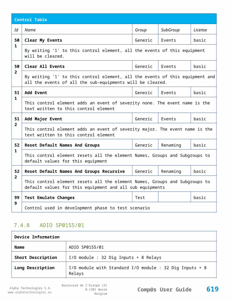
Alpha Technologies S.A.www.alphatechnologies.eu
Alpha Technologies S.A.www.alphatechnologies.eu
Comp@s User GuideBoulevard de l’Europe 131
B-1301 WavreBelgium
Data Table
AC input power value (W) group 2
429 Input Apparent Power AC Inputs AC Input 2 VA basic
AC input apparent power value (VA) group 2
430 Input Frequency AC Inputs AC Input 2 Hz basic
AC input frequency (Hz) group 2
431 Number Of Modules delivering output AC Inputs AC Input 2 basic
Number of modules that are delivering output in the group 2
432 Number Of Modules manually off AC Inputs AC Input 2 basic
Number of modules manually off in the group 2
433 Number Of Modules in failure AC Inputs AC Input 2 basic
Number of modules that are not delivering output due to a failure in the group 2
434 Number Of Modules seen by T2S AC Inputs AC Input 2 basic
Number of modules seen by T2S in the group 2
435 Number Of Modules stating AC input OK AC Inputs AC Input 2 basic
Number of modules stating AC input is OK group 2
451 Input Voltage AC Inputs AC Input 3 Volt basic
AC input voltage value (V) group 3
452 Input Current AC Inputs AC Input 3 Ampere basic
AC input current value (A) group 3
453 Input Power AC Inputs AC Input 3 Watt basic
AC input power value (W) group 3
454 Input Apparent Power AC Inputs AC Input 3 VA basic
AC input apparent power value (VA) group 3
455 Input Frequency AC Inputs AC Input 3 Hz basic
AC input frequency (Hz) group 3
456 Number Of Modules delivering output AC Inputs AC Input 3 basic
Number of modules that are delivering output in the group 3
619

Alpha Technologies S.A.www.alphatechnologies.eu
Alpha Technologies S.A.www.alphatechnologies.eu
Comp@s User GuideBoulevard de l’Europe 131
B-1301 WavreBelgium
Data Table
457 Number Of Modules manually off AC Inputs AC Input 3 basic
Number of modules manually off in the group 3
458 Number Of Modules in failure AC Inputs AC Input 3 basic
Number of modules that are not delivering output due to a failure in the group 3
459 Number Of Modules seen by T2S AC Inputs AC Input 3 basic
Number of modules seen by T2S in the group 3
460 Number Of Modules stating AC input OK AC Inputs AC Input 3 basic
Number of modules stating AC input is OK group 3
476 Input Voltage AC Inputs AC Input 4 Volt basic
AC input voltage value (V) group 4
477 Input Current AC Inputs AC Input 4 Ampere basic
AC input current value (A) group 4
478 Input Power AC Inputs AC Input 4 Watt basic
AC input power value (W) group 4
479 Input Apparent Power AC Inputs AC Input 4 VA basic
AC input apparent power value (VA) group 4
480 Input Frequency AC Inputs AC Input 4 Hz basic
AC input frequency (Hz) group 4
481 Number Of Modules delivering output AC Inputs AC Input 4 basic
Number of modules that are delivering output in the group 4
482 Number Of Modules manually off AC Inputs AC Input 4 basic
Number of modules manually off in the group 4
483 Number Of Modules in failure AC Inputs AC Input 4 basic
Number of modules that are not delivering output due to a failure in the group 4
484 Number Of Modules seen by T2S AC Inputs AC Input 4 basic
Number of modules seen by T2S in the group 4
485 Number Of Modules stating AC input OK AC Inputs AC Input 4 basic
620

Alpha Technologies S.A.www.alphatechnologies.eu
Alpha Technologies S.A.www.alphatechnologies.eu
Comp@s User GuideBoulevard de l’Europe 131
B-1301 WavreBelgium
Data Table
Number of modules stating AC input is OK group 4
501 Input Current DC Inputs DC Input 1 Ampere basic
DC input current value in amperes group 1
502 Input Power DC Inputs DC Input 1 Watt basic
DC input power value in watts group 1
526 Input Current DC Inputs DC Input 2 Ampere basic
DC input current value in amperes group 2
527 Input Power DC Inputs DC Input 2 Watt basic
DC input power value in watts group 2
551 Input Current DC Inputs DC Input 3 Ampere basic
DC input current value in amperes group 3
552 Input Power DC Inputs DC Input 3 Watt basic
DC input power value in watts group 3
576 Input Current DC Inputs DC Input 4 Ampere basic
DC input current value in amperes group 4
577 Input Power DC Inputs DC Input 4 Watt basic
DC input power value in watts group 4
601 Input Current DC Inputs DC Input 5 Ampere basic
DC input current value in amperes group 5
602 Input Power DC Inputs DC Input 5 Watt basic
DC input power value in watts group 5
626 Input Current DC Inputs DC Input 6 Ampere basic
DC input current value in amperes group 6
627 Input Power DC Inputs DC Input 6 Watt basic
DC input power value in watts group 6
651 Input Current DC Inputs DC Input 7 Ampere basic
DC input current value in amperes group 7
621
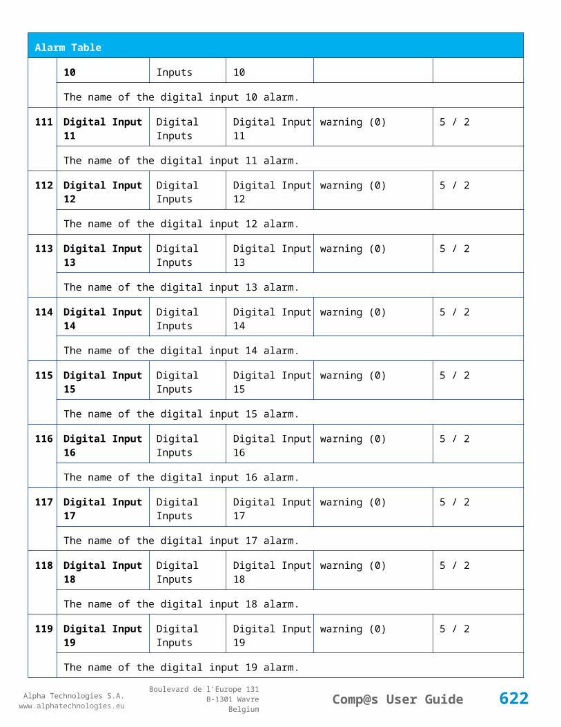
Alpha Technologies S.A.www.alphatechnologies.eu
Alpha Technologies S.A.www.alphatechnologies.eu
Comp@s User GuideBoulevard de l’Europe 131
B-1301 WavreBelgium
Data Table
652 Input Power DC Inputs DC Input 7 Watt basic
DC input power value in watts group 7
676 Input Current DC Inputs DC Input 8 Ampere basic
DC input current value in amperes group 8
677 Input Power DC Inputs DC Input 8 Watt basic
DC input power value in watts group 8
701 Alarm Id List Error List basic
List of active manufacturer specific alarms
702 Alarm Name List Error List basic
List of active manufacturer specific alarms
Config Table
Id Name Group SubGroup Unit Range: Min/Max (default)
License
1 Number of AC Output Groups To Configure
Inverter System
Group Config basic
Number of AC output groups that must be displayed in configuration
2 Number of AC Input Groups To Configure
Inverter System
Group Config basic
Number of AC input groups that must be displayed in configuration
3 Number of DC Input Groups To Configure
Inverter System
Group Config basic
Number of DC input groups that must be displayed in configuration
5 Input Ratio On DC Inverter System
basic
0-100 : 0 full AC, 100 full AC
21 AC Input Frequency Low Start AC Inputs Input Frequency
Hz 0/1000 (0) basic
The AC frequency low start in hertz.
22 AC Input Frequency Low Stop AC Inputs Input Frequency
Hz 0/1000 (0) basic
622

Alpha Technologies S.A.www.alphatechnologies.eu
Alpha Technologies S.A.www.alphatechnologies.eu
Comp@s User GuideBoulevard de l’Europe 131
B-1301 WavreBelgium
Config Table
The AC frequency low stop in hertz.
23 AC Input Frequency High Start AC Inputs Input Frequency
Hz 0/1000 (0) basic
The AC frequency high start in hertz.
24 AC Input Frequency High Stop AC Inputs Input Frequency
Hz 0/1000 (0) basic
The AC frequency high stop in hertz.
101
Number of Modules AC Outputs AC Output 1 basic
The number of modules in phase 1
102
Amount of Redundancy AC Outputs AC Output 1 basic
The amount of redundancy in phase 1
103
Phase Shift AC Outputs AC Output 1 degree
basic
The phase shift in degrees in phase 1
104
Nominal Output Voltage AC Outputs AC Output 1 Volt 0/250 (120) basic
The output voltage 1 in volts phase 1
111
Number of Modules AC Outputs AC Output 2 basic
The number of modules in phase 2
112
Amount of Redundancy AC Outputs AC Output 2 basic
The amount of redundancy in phase 2
113
Phase Shift AC Outputs AC Output 2 degree
basic
The phase shift in degrees in phase 2
114
Nominal Output Voltage AC Outputs AC Output 2 Volt 0/250 (120) basic
The output voltage 1 in volts phase 2
121
Number of Modules AC Outputs AC Output 3 basic
The number of modules in phase 3
122
Amount of Redundancy AC Outputs AC Output 3 basic
The amount of redundancy in phase 3
623

Alpha Technologies S.A.www.alphatechnologies.eu
Alpha Technologies S.A.www.alphatechnologies.eu
Comp@s User GuideBoulevard de l’Europe 131
B-1301 WavreBelgium
Config Table
123
Phase Shift AC Outputs AC Output 3 degree
basic
The phase shift in degrees in phase 3
124
Nominal Output Voltage AC Outputs AC Output 3 Volt 0/250 (120) basic
The output voltage 1 in volts phase 3
131
Number of Modules AC Outputs AC Output 4 basic
The number of modules in phase 4
132
Amount of Redundancy AC Outputs AC Output 4 basic
The amount of redundancy in phase 4
133
Phase Shift AC Outputs AC Output 4 degree
basic
The phase shift in degrees in phase 4
134
Nominal Output Voltage AC Outputs AC Output 4 Volt 0/250 (120) basic
The output voltage 1 in volts phase 4
141
Number of Modules AC Outputs AC Output 5 basic
The number of modules in phase 5
142
Amount of Redundancy AC Outputs AC Output 5 basic
The amount of redundancy in phase 5
143
Phase Shift AC Outputs AC Output 5 degree
basic
The phase shift in degrees in phase 5
144
Nominal Output Voltage AC Outputs AC Output 5 Volt 0/250 (120) basic
The output voltage 1 in volts phase 5
151
Number of Modules AC Outputs AC Output 6 basic
The number of modules in phase 6
152
Amount of Redundancy AC Outputs AC Output 6 basic
The amount of redundancy in phase 6
153
Phase Shift AC Outputs AC Output 6 degree
basic
624
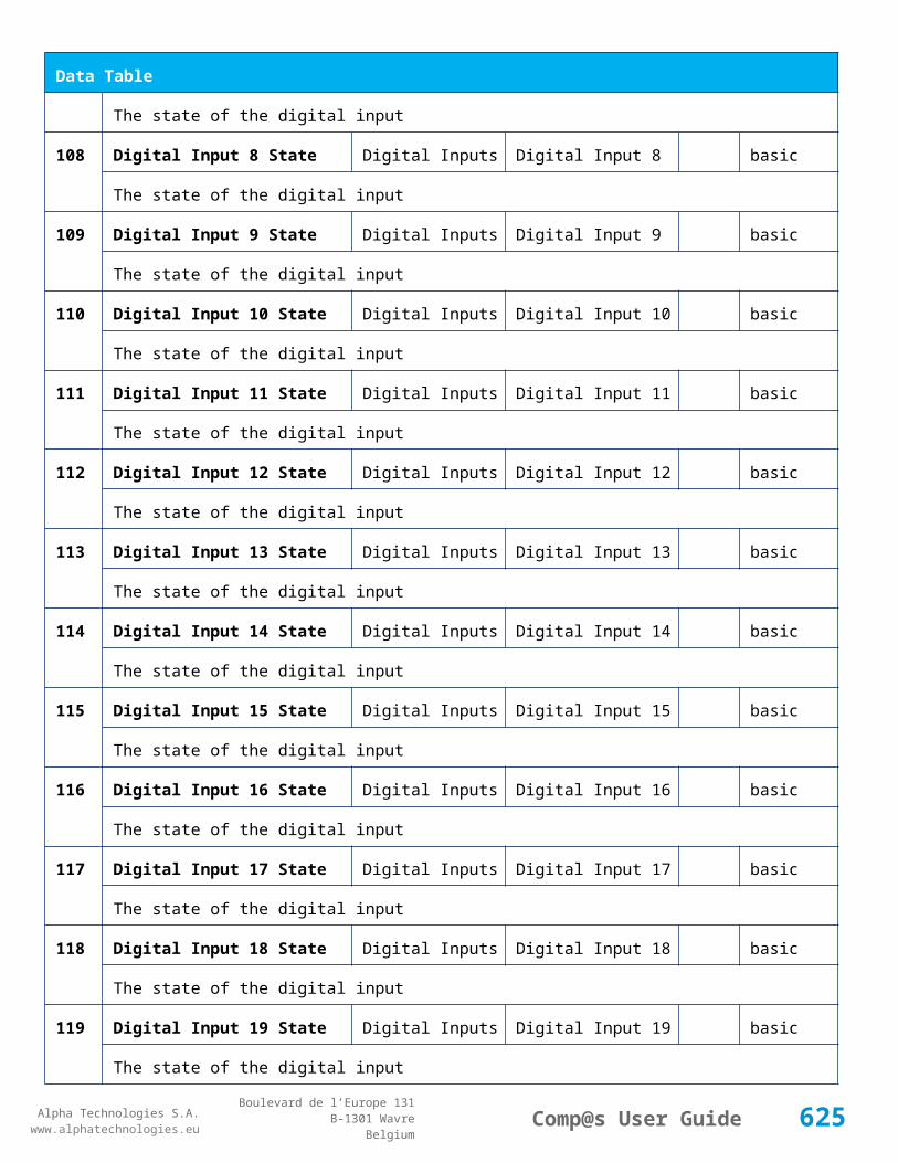
Alpha Technologies S.A.www.alphatechnologies.eu
Alpha Technologies S.A.www.alphatechnologies.eu
Comp@s User GuideBoulevard de l’Europe 131
B-1301 WavreBelgium
Config Table
The phase shift in degrees in phase 6
154
Nominal Output Voltage AC Outputs AC Output 6 Volt 0/250 (120) basic
The output voltage 1 in volts phase 6
161
Number of Modules AC Outputs AC Output 7 basic
The number of modules in phase 7
162
Amount of Redundancy AC Outputs AC Output 7 basic
The amount of redundancy in phase 7
163
Phase Shift AC Outputs AC Output 7 degree
basic
The phase shift in degrees in phase 7
164
Nominal Output Voltage AC Outputs AC Output 7 Volt 0/250 (120) basic
The output voltage 1 in volts phase 7
171
Number of Modules AC Outputs AC Output 8 basic
The number of modules in phase 8
172
Amount of Redundancy AC Outputs AC Output 8 basic
The amount of redundancy in phase 8
173
Phase Shift AC Outputs AC Output 8 degree
basic
The phase shift in degrees in phase 8
174
Nominal Output Voltage AC Outputs AC Output 8 Volt 0/250 (120) basic
The output voltage 1 in volts phase 8
201
Vac In Low Start AC Inputs AC Input 1 Volt 0/300 (0) basic
The AC input low start in volts group 1
202
Vac In Low Transfer AC Inputs AC Input 1 Volt 0/300 (0) basic
The AC input low transfer in volts group 1
203
Vac In Low Stop AC Inputs AC Input 1 Volt 0/300 (0) basic
The AC input low stop in volts group 1
20 Vac In High Start AC Inputs AC Input 1 Volt 0/300 (0) basic
625

Alpha Technologies S.A.www.alphatechnologies.eu
Alpha Technologies S.A.www.alphatechnologies.eu
Comp@s User GuideBoulevard de l’Europe 131
B-1301 WavreBelgium
Config Table
4 The AC input high start in volts group 1
205
Vac In High Transfer AC Inputs AC Input 1 Volt 0/300 (0) basic
The AC input high transfer in volts group 1
206
Vac In High Stop AC Inputs AC Input 1 Volt 0/300 (0) basic
The AC input high stop in volts group 1
211
Vac In Low Start AC Inputs AC Input 2 Volt 0/300 (0) basic
The AC input low start in volts group 2
212
Vac In Low Transfer AC Inputs AC Input 2 Volt 0/300 (0) basic
The AC input low transfer in volts group 2
213
Vac In Low Stop AC Inputs AC Input 2 Volt 0/300 (0) basic
The AC input low stop in volts group 2
214
Vac In High Start AC Inputs AC Input 2 Volt 0/300 (0) basic
The AC input high start in volts group 2
215
Vac In High Transfer AC Inputs AC Input 2 Volt 0/300 (0) basic
The AC input high transfer in volts group 2
216
Vac In High Stop AC Inputs AC Input 2 Volt 0/300 (0) basic
The AC input high stop in volts group 2
221
Vac In Low Start AC Inputs AC Input 3 Volt 0/300 (0) basic
The AC input low start in volts group 3
222
Vac In Low Transfer AC Inputs AC Input 3 Volt 0/300 (0) basic
The AC input low transfer in volts group 3
223
Vac In Low Stop AC Inputs AC Input 3 Volt 0/300 (0) basic
The AC input low stop in volts group 3
224
Vac In High Start AC Inputs AC Input 3 Volt 0/300 (0) basic
The AC input high start in volts group 3
225
Vac In High Transfer AC Inputs AC Input 3 Volt 0/300 (0) basic
The AC input high transfer in volts group 3
626
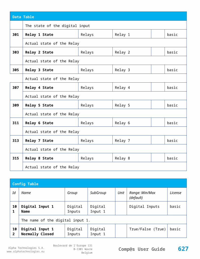
Alpha Technologies S.A.www.alphatechnologies.eu
Alpha Technologies S.A.www.alphatechnologies.eu
Comp@s User GuideBoulevard de l’Europe 131
B-1301 WavreBelgium
Config Table
226
Vac In High Stop AC Inputs AC Input 3 Volt 0/300 (0) basic
The AC input high stop in volts group 3
231
Vac In Low Start AC Inputs AC Input 4 Volt 0/300 (0) basic
The AC input low start in volts group 4
232
Vac In Low Transfer AC Inputs AC Input 4 Volt 0/300 (0) basic
The AC input low transfer in volts group 4
233
Vac In Low Stop AC Inputs AC Input 4 Volt 0/300 (0) basic
The AC input low stop in volts group 4
234
Vac In High Start AC Inputs AC Input 4 Volt 0/300 (0) basic
The AC input high start in volts group 4
235
Vac In High Transfer AC Inputs AC Input 4 Volt 0/300 (0) basic
The AC input high transfer in volts group 4
236
Vac In High Stop AC Inputs AC Input 4 Volt 0/300 (0) basic
The AC input high stop in volts group 4
301
Vdc In Low Start DC Inputs DC Input 1 Volt 0/80 (0) basic
The DC input low start in volts group 1
302
Vdc In Low Transfer DC Inputs DC Input 1 Volt 0/80 (0) basic
The DC input low transfer in volts group 1
303
Vdc In Low Stop DC Inputs DC Input 1 Volt 0/80 (0) basic
The DC input low stop in volts group 1
304
Vdc In High Start DC Inputs DC Input 1 Volt 0/80 (0) basic
The DC input high start in volts group 1
305
Vdc In High Transfer DC Inputs DC Input 1 Volt 0/80 (0) basic
The DC input high transfer in volts group 1
306
Vdc In High Stop DC Inputs DC Input 1 Volt 0/80 (0) basic
The DC input high stop in volts group 1
31 Vdc In Low Start DC Inputs DC Input 2 Volt 0/80 (0) basic
627

Alpha Technologies S.A.www.alphatechnologies.eu
Alpha Technologies S.A.www.alphatechnologies.eu
Comp@s User GuideBoulevard de l’Europe 131
B-1301 WavreBelgium
Config Table
1 The DC input low start in volts group 2
312
Vdc In Low Transfer DC Inputs DC Input 2 Volt 0/80 (0) basic
The DC input low transfer in volts group 2
313
Vdc In Low Stop DC Inputs DC Input 2 Volt 0/80 (0) basic
The DC input low stop in volts group 2
314
Vdc In High Start DC Inputs DC Input 2 Volt 0/80 (0) basic
The DC input high start in volts group 2
315
Vdc In High Transfer DC Inputs DC Input 2 Volt 0/80 (0) basic
The DC input high transfer in volts group 2
316
Vdc In High Stop DC Inputs DC Input 2 Volt 0/80 (0) basic
The DC input high stop in volts group 2
321
Vdc In Low Start DC Inputs DC Input 3 Volt 0/80 (0) basic
The DC input low start in volts group 3
322
Vdc In Low Transfer DC Inputs DC Input 3 Volt 0/80 (0) basic
The DC input low transfer in volts group 3
323
Vdc In Low Stop DC Inputs DC Input 3 Volt 0/80 (0) basic
The DC input low stop in volts group 3
324
Vdc In High Start DC Inputs DC Input 3 Volt 0/80 (0) basic
The DC input high start in volts group 3
325
Vdc In High Transfer DC Inputs DC Input 3 Volt 0/80 (0) basic
The DC input high transfer in volts group 3
326
Vdc In High Stop DC Inputs DC Input 3 Volt 0/80 (0) basic
The DC input high stop in volts group 3
331
Vdc In Low Start DC Inputs DC Input 4 Volt 0/80 (0) basic
The DC input low start in volts group 4
332
Vdc In Low Transfer DC Inputs DC Input 4 Volt 0/80 (0) basic
The DC input low transfer in volts group 4
628

Alpha Technologies S.A.www.alphatechnologies.eu
Alpha Technologies S.A.www.alphatechnologies.eu
Comp@s User GuideBoulevard de l’Europe 131
B-1301 WavreBelgium
Config Table
333
Vdc In Low Stop DC Inputs DC Input 4 Volt 0/80 (0) basic
The DC input low stop in volts group 4
334
Vdc In High Start DC Inputs DC Input 4 Volt 0/80 (0) basic
The DC input high start in volts group 4
335
Vdc In High Transfer DC Inputs DC Input 4 Volt 0/80 (0) basic
The DC input high transfer in volts group 4
336
Vdc In High Stop DC Inputs DC Input 4 Volt 0/80 (0) basic
The DC input high stop in volts group 4
341
Vdc In Low Start DC Inputs DC Input 5 Volt 0/80 (0) basic
The DC input low start in volts group 5
342
Vdc In Low Transfer DC Inputs DC Input 5 Volt 0/80 (0) basic
The DC input low transfer in volts group 5
343
Vdc In Low Stop DC Inputs DC Input 5 Volt 0/80 (0) basic
The DC input low stop in volts group 5
344
Vdc In High Start DC Inputs DC Input 5 Volt 0/80 (0) basic
The DC input high start in volts group 5
345
Vdc In High Transfer DC Inputs DC Input 5 Volt 0/80 (0) basic
The DC input high transfer in volts group 5
346
Vdc In High Stop DC Inputs DC Input 5 Volt 0/80 (0) basic
The DC input high stop in volts group 5
351
Vdc In Low Start DC Inputs DC Input 6 Volt 0/80 (0) basic
The DC input low start in volts group 6
352
Vdc In Low Transfer DC Inputs DC Input 6 Volt 0/80 (0) basic
The DC input low transfer in volts group 6
353
Vdc In Low Stop DC Inputs DC Input 6 Volt 0/80 (0) basic
The DC input low stop in volts group 6
35 Vdc In High Start DC Inputs DC Input 6 Volt 0/80 (0) basic
629

Alpha Technologies S.A.www.alphatechnologies.eu
Alpha Technologies S.A.www.alphatechnologies.eu
Comp@s User GuideBoulevard de l’Europe 131
B-1301 WavreBelgium
Config Table
4 The DC input high start in volts group 6
355
Vdc In High Transfer DC Inputs DC Input 6 Volt 0/80 (0) basic
The DC input high transfer in volts group 6
356
Vdc In High Stop DC Inputs DC Input 6 Volt 0/80 (0) basic
The DC input high stop in volts group 6
361
Vdc In Low Start DC Inputs DC Input 7 Volt 0/80 (0) basic
The DC input low start in volts group 7
362
Vdc In Low Transfer DC Inputs DC Input 7 Volt 0/80 (0) basic
The DC input low transfer in volts group 7
363
Vdc In Low Stop DC Inputs DC Input 7 Volt 0/80 (0) basic
The DC input low stop in volts group 7
364
Vdc In High Start DC Inputs DC Input 7 Volt 0/80 (0) basic
The DC input high start in volts group 7
365
Vdc In High Transfer DC Inputs DC Input 7 Volt 0/80 (0) basic
The DC input high transfer in volts group 7
366
Vdc In High Stop DC Inputs DC Input 7 Volt 0/80 (0) basic
The DC input high stop in volts group 7
371
Vdc In Low Start DC Inputs DC Input 8 Volt 0/80 (0) basic
The DC input low start in volts group 8
372
Vdc In Low Transfer DC Inputs DC Input 8 Volt 0/80 (0) basic
The DC input low transfer in volts group 8
373
Vdc In Low Stop DC Inputs DC Input 8 Volt 0/80 (0) basic
The DC input low stop in volts group 8
374
Vdc In High Start DC Inputs DC Input 8 Volt 0/80 (0) basic
The DC input high start in volts group 8
375
Vdc In High Transfer DC Inputs DC Input 8 Volt 0/80 (0) basic
The DC input high transfer in volts group 8
630
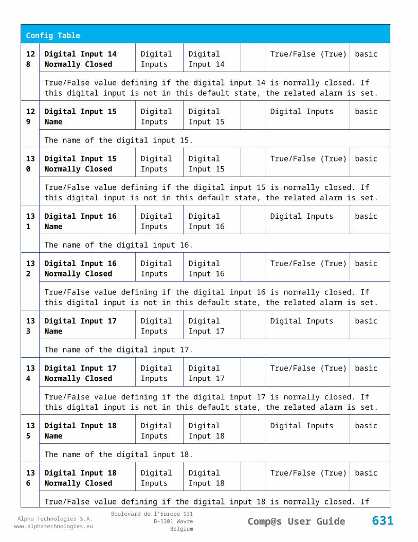
Alpha Technologies S.A.www.alphatechnologies.eu
Alpha Technologies S.A.www.alphatechnologies.eu
Comp@s User GuideBoulevard de l’Europe 131
B-1301 WavreBelgium
Config Table
376
Vdc In High Stop DC Inputs DC Input 8 Volt 0/80 (0) basic
The DC input high stop in volts group 8
Control Table
Id Name Group SubGroup License
1 Load Actual Configuration Running on T2S Inverter System basic
This control will reload the configuration of the T2S inside the Configuration Element of the Inverter System. It returns 'command canceled' if all the information is not yet read
2 Save Configuration To T2S Inverter System basic
Save Configuration To T2S
11 Turn All Modules Off Inverter System basic
Turn All Modules Off
12 Turn All Modules On Inverter System basic
Turn All Modules Off
501
Clear My Events Generic Events basic
By writing '1' to this control element, all the events of this equipment will be cleared.
502
Clear All Events Generic Events basic
By writing '1' to this control element, all the events of this equipment and all the events of all the sub-equipments will be cleared.
511
Add Event Generic Events basic
This control element adds an event of severity none. The event name is the text written to this control element
512
Add Major Event Generic Events basic
This control element adds an event of severity major. The event name is the text written to this control element
521
Reset Default Names And Groups Generic Renaming basic
This control element resets all the element Names, Groups and Subgroups to default values for this equipment
522
Reset Default Names And Groups Recursive Generic Renaming basic
This control element resets all the element Names, Groups and Subgroups to default values for this
631

Alpha Technologies S.A.www.alphatechnologies.eu
Alpha Technologies S.A.www.alphatechnologies.eu
Comp@s User GuideBoulevard de l’Europe 131
B-1301 WavreBelgium
Control Table
equipment and all sub equipments
632

Alpha Technologies S.A.www.alphatechnologies.eu
Alpha Technologies S.A.www.alphatechnologies.eu
Comp@s User GuideBoulevard de l’Europe 131
B-1301 WavreBelgium
8 LICENSES
The Comp@s license packages
How can I upgrade my license?
How is the license stored?
8.1 The Comp@s license packages
The Comp@s software has functionalities which are accessible depending of the licensed options. For the time being, 4 license packages are available: battery, asset, plc and modbus.
The Battery Package
The Asset Package
The PLC Package
The Modbus Package
License currently in use.
8.1.1 The Battery Package
This package allows using advanced functionalities related to the battery management. It allows configuring and starting battery test, it allows to retrieve test battery records, etc. The detailed table, in chapter 8, details the table entries only available with the battery package.
8.1.2 The Asset Package
This package allows:
To retrieve any available data record, with a resolution of second, minute, hour or day. This includes also some statistics about the data. The records can be viewed with a web browser with Flash installed. The records can also be downloaded in CSV;
To retrieve any information about the components of a system, like serial numbers, batch ids, production dates, software information, etc;
To retrieve detailed information about smart rectifiers;
To use strategy to optimize the global efficiency.
Note: The PLC package is also included in the Asset Package.
8.1.3 The PLC Package
This PLC package allows:
The creation of customer defined data, like in a Programmable Logic Controller: a PCL Data is defined by any mathematical operation over any data;
633

Alpha Technologies S.A.www.alphatechnologies.eu
Alpha Technologies S.A.www.alphatechnologies.eu
Comp@s User GuideBoulevard de l’Europe 131
B-1301 WavreBelgium
The creation of customer defined alarms, like in a Programmable Logic Controller: a PLC Alarm is defined by any combination of any data and any alarm.
8.1.4 The Modbus Package
This Mobdus package allows retrieving the data and the alarms related to one dc system with the Modbus RTU over TCP protocol. This protocol is used in some industrial environment.
8.1.5 License currently in use
In order to check which license is currently used by Comp@s, browse to SiteàData. The entry “Licensed Options” provides the information, as shown on the following figure:
Figure 89 Installed License
8.2 How can I upgrade my license?
If you want to unlock functionalities thanks to a new license:
STEP 1: Please contact your vendor.
STEP 2: He will ask you to send you actual license file.
STEP 3: A new license file will be returned.
STEP 4: Copy it to \\FlashDisk\\User
STEP 5: After a reboot, your system is using the new license.
8.3 How is the license stored?
The Comp@s license is a XML file named “licenseKey_XX-XX-XX-XX-XX-XX.xml”, where XX-XX…-XX is the registered MAC address, in hexadecimal. (Example: licenseKey_00-14-2D-20-0B-20.xml) When the file is installed at factory, it is located in “\\FlashDisk\Factory”.
The content of this XML file looks like:
XML licence file content:<licenseKey version="1.0">
<product version="0.1.X.X">Alpha Technologies Comp@s</product>
<macAddress>00-14-2D-20-0B-20</macAddress>
<options>asset,battery</options> <key>vddR+a7oQcx4Qrmt24padm3hSd1DJtbC3LEsKtzxdSJ5mCloN9uZMg
634

Alpha Technologies S.A.www.alphatechnologies.eu
Alpha Technologies S.A.www.alphatechnologies.eu
Comp@s User GuideBoulevard de l’Europe 131
B-1301 WavreBelgium
NnvemA13CWE5pOZxZBJY/uTsuCPHEwAQ==</key>
</licenseKey>
The interesting part is “<options>asset,battery</options>” which corresponds to the licensed option you bought.
Note that this license is unique on each monitoring. If you copy a license file from one monitoring to another, it will not work!
635

Alpha Technologies S.A.www.alphatechnologies.eu
Alpha Technologies S.A.www.alphatechnologies.eu
Comp@s User GuideBoulevard de l’Europe 131
B-1301 WavreBelgium
9 SOFTWARE RELEASE COMPONENTS
A comp@s release is composed of different components.
Comp@s is evolving every day to satisfy new customer and new products needs. It supports more and more devices.
When required, we release a production release.This release is composed of the following components :
System bootloader
The Operating System
Comp@s Starter Executable
Comp@s Executable
Comp@s FTP Server Executable.
9.1 System bootloader
The Bootloader is the first piece of code being executed at start-up. Its main purpose is to load and start the OS (WinCE). The Boot loader is also the place where various settings can be changed.
9.2 The Operating System
Comp@s is running on Windows CE 5.0 operating system, featuring nice features like:
Real Time
A reliable TCP/IP stack
USB driver for local connection
Fast development capabilities.
The system image is build with the Microsoft Platform Builder. It uses the Toradex BSP (Board Support Package).
An external watchdog system is present to automatically restart the monitoring application if loss of activity is detected.
Microsoft® Windows® CE 5.0 is an open, scalable, 32-bit operating system (OS) that integrates reliable, real time capabilities with advanced Windows technologies. Windows CE allows you to build a wide range of innovative, small footprint devices. A typical Windows CE–based device is designed for a specific use, often runs disconnected from other computers, and requires a small OS that has a deterministic response to interrupts. Examples include enterprise tools, such as industrial controllers, communications hubs, and point-of-sale terminals, and consumer products, such as cameras, Internet appliances, and interactive televisions.
See MSDN Win CE 5.0 for more information: http://msdn.microsoft.com/en-us/library/ms905511.aspx.
636
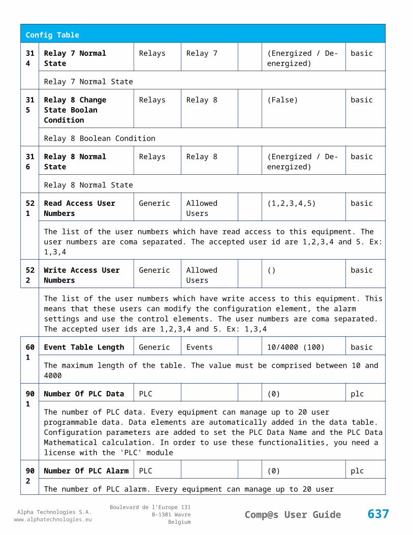
Alpha Technologies S.A.www.alphatechnologies.eu
Alpha Technologies S.A.www.alphatechnologies.eu
Comp@s User GuideBoulevard de l’Europe 131
B-1301 WavreBelgium
9.3 Comp@s Starter Executable
That application is stored on the Flash, in the AutoRun folder. The exact file name is : "Compas_Starter.exe".
The application is written in c# and run over the .NET CF 2.0.
9.4 Comp@s Executable
The application is written in c# and run over the .NET CF 2.0.
When Compas is executed, the followings tasks are run:
1. Extract and load of C Drivers
2. Retrieve Environment Configuration
3. Load License
4. Load Translation Dictionary
5. Create a Site Object
6. Create Thread “Decode CAN Msg ” >
7. Create Thread “Web Server”
8. Create Thread SNMP
9. Create Thread “Modbus Slave”
10. Create Thread “Modbus Master”
11. Create Thread “ProcessScheduledTasks".
9.4.1 C Drivers
In order to guarantee fast and reliable CAN communication, the can drivers is build in a C DLL (Dynamic Link Library).
The driver is not build in the operating system to allow easy upgrade and avoid compatibility issues.
The hardware CAN controller model is Microchip MCP 2515. It provides a SPI interface used to communicate with the Compas electronic board.
Microchip MCP 2515 details.
9.4.1.1 CAN Message ReceivingEach time a message is received, the MCP 2515 use hardware interrupt to request the driver to read the new message.
The CAN messages are stored in a large circular buffer queue. These messages can be read without real time issues.
9.4.1.2 CAN Message SendingMessage can be sent via 3 different output buffers:
High Priority Buffer
Normal Priority Buffer
637

Alpha Technologies S.A.www.alphatechnologies.eu
Alpha Technologies S.A.www.alphatechnologies.eu
Comp@s User GuideBoulevard de l’Europe 131
B-1301 WavreBelgium
Low Priority Buffer
They can be sent one by one or in block of maximum 10 messages. (Block sending is required by the CANOpen LSS algorithm to guarantee the message order)
9.4.1.3 Other Driver FunctionsThe C driver is also used to control led, and to reset the hardware watchdog, depending of the hardware configuration.
9.4.2 Environment Configuration
Global variables are configured depending of the environment:
BSP Version
Flash path
Ethernet Device.
9.4.2.1 BSP VersionThe Board Support Package is related to the operating system version.
9.4.2.2 Flash pathDefault path to access the flash memory is \\FlashDisk
But, on previous versions of Compas, \\NOR Flash was used.
9.4.2.3 Ethernet DeviceDepending of the comp@s hardware revision, different chipset are used for Ethernet:
DM90001
AX887961
9.4.3 License
The license is validated and loaded if trusted.
9.4.4 Translation Dictionary
On start-up, the list of all the used strings is generated dynamically.
Then, the associated translations are loaded in memory from csv files stored in the user dedicated Flash.
The Namespace in charge of the translations is Compas.Strings.
9.4.5 Site Object
The site object is the root node of the equipments controlled and monitored by Compas.
Any detected equipment/device will be a child of this object.
After the object creation, the associated site configuration is loaded.
638

Alpha Technologies S.A.www.alphatechnologies.eu
Alpha Technologies S.A.www.alphatechnologies.eu
Comp@s User GuideBoulevard de l’Europe 131
B-1301 WavreBelgium
9.4.6 Decode CAN Msg
See MonitoringThreadDecodeCANMsg()()()()
9.4.7 Web Server Interface
The internal Web server of the application is launched at startup in a separate thread. It is constituted of an request extractor that listens to the HTTP messages, and calls back a method to process them.
Default listening port number is 80.
9.4.8 SNMP Management
A new SNMP agent is instantiated at application startup. This agent is called in order to send an event trap each time a new event is added by an equipment.
9.4.9 Process Scheduled Tasks
This thread is looping on the function “ProcessTasks”, and sleep 20 milliseconds after each execution. It executes the following tasks:
Execute the “RefreshSlow” of all the equipments. It recalculate the internal variables, the PLC data, manage the regulation, etc. (Every 1000ms)
Execute the “UpdateAlarmTableAndStatus” of all the equipments. It recalculate each alarm, and update the global status of the equipment. (Every 1000ms)
Update Led status, for led controlled directly by Comp@s. (every 100ms)
Ask necessary CANOpen variables refresh (every 100ms)
Manage CANOpen Nodes, detect nodes to remove (Every 1500ms)
Check if new CANOpen LSS node has been detected (Every 2000ms)
Refresh the equipment structure if needed (Every 2000ms)
Send SNMP trap if Authentication Failure (Every 2000ms)
Process Data Records elements with second resolution (Every 1 sec)
Process Data Records elements with minute resolution (Every time the system ime as changed of minute)
Process Data Records elements with hour resolution (Every time the system time as changed of hour)
Archive Data records (Every x hours if x is configured and different of 0)
Process Data Records elements with day resolution, and save all records in flash (Every time the system time as changed of day)
Post XML events if any and if configured, for all equipments (Every 2 seconds)
9.4.10 Inventory Management and Equipment Mounting
The device inventory is initialized and loaded at startup. First application is searching for the file devices.xml in \\User\\ directory of the flash memory path. If this file doesn't exist, a default initialization procedure is started.
Procedure is the following:
639

Alpha Technologies S.A.www.alphatechnologies.eu
Alpha Technologies S.A.www.alphatechnologies.eu
Comp@s User GuideBoulevard de l’Europe 131
B-1301 WavreBelgium
If a site doesn't exist, application is creating or getting one. Getting one means that application is searching for an equipment with the same name or ID. Otherwise, a new site is created.
If an energy system doesn't exist, application is creating or getting one.
After CAN bus initialization, LSS (Layer Setting Services) messages are processed. Each time a new CANOpen node is found, corresponding device is added to the device dictionary.
9.4.11 Alarm Set-up and Clearance
Each time a new alarm is created, two "Set" and "Clear" delay parameters are associated to it. By default they are equal to 0 and 2 seconds respectively:
Alarm is set if its severity type is different to "Disabled" AND if its alarm condition is true since a time in seconds superior to the set delay parameter.
Alarm is cleared if its alarm condition is NOT true since a time in seconds superior to the clear delay parameter.
9.4.12 System and Application Configuration
Each equipment of the application possess its own configuration elements. They appear in the Web page Config tab related to the equipment in order to be editable by application user.
9.4.13 Data Record Management
In addition to instantaneous Data objects, the application manages Data Records objects that accumulate information from Data objects. Real-time statistics like average, max. and min. values are computed. The Comp@s Web server uses an integrated javascript applet in order to generate a dyncamical display of the data record information.
9.4.14 Equipment Emulation
If equipment emulation is used, CANDriver is emulating a set of equipments by sending corresponding CAN messages.
9.5 Comp@s FTP Server Executable
The application is written in c# and run over the .NET CF 2.0.
This program implements a FTP server. The program is separated from Comp@s to allow software upgrade also when Compas.exe is not running. The security management is separated from the Comp@s one.
File Transfer Protocol (FTP) is a standard network protocol used to transfer files from one host to another host over a TCP-based network, such as the Internet. FTP is built on a client-server architecture and uses separate control and data connections between the client and server.
Wikipedia - FTP
640
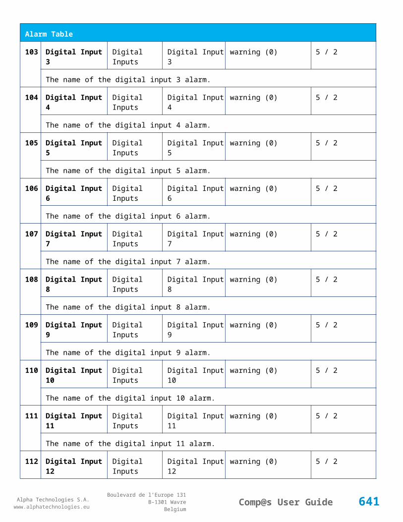
Alpha Technologies S.A.www.alphatechnologies.eu
Alpha Technologies S.A.www.alphatechnologies.eu
Comp@s User GuideBoulevard de l’Europe 131
B-1301 WavreBelgium
1 0 S O F T W A R E C H A N G E L O G
.NET Executable Versioning
Comp@s Changelog.
10.1 .NET Executable Versioning
The software versioning is the process of assigning unique version numbers to unique states of computer software. Each assembly has a version number as part of its identity.
Since March 2012, the standardized format used is :
<major version>.<minor version>.<build number>.<revision>
All the fields are integers.
The major version changes when a release is made that breaks backwards compatibility.
The minor version will be used in other cases when we release versions.
The build number increments as we do code reviews and check in working code to the repository . (this number is not displayed to the customer to avoid confusion - it is showned as 0.
The revision is used for internal build, it designate alpha or beta status for releases that are not stable enough for general or practical deployment and are intended for testing/internal use only:
o <revision> - 0 : for alpha (non-stable)
o <revision> - 1: for beta (internal)
o <revision> - 2 : for release candidate (QA-passed, final tests)
o <revision> - 3 : for public (release)
o <revision> - 4 and following : for releasing specific modifications on a released version (for specific customers - should be avoided as much as possible)
Before that version, the used format was:
0.Y.0.X where:
X is the minor revision number and is:
o odd for beta version
o even for stable version
Y is the major revision number.
10.2 Comp@s Changelog
Note: Only revisions with a SOFT 000031 XX code were released in production. The other versions were distributed to customers for upgrade when necessary.
641

Alpha Technologies S.A.www.alphatechnologies.eu
Alpha Technologies S.A.www.alphatechnologies.eu
Comp@s User GuideBoulevard de l’Europe 131
B-1301 WavreBelgium
Legend:+ Added feature* Improved/changed feature- Bug fixed! Known issue / missing feature
Revision 2.11.0.4 (24/07/2014) - SOFT 000031 47
- Event name was not correct for alarm related events. 'Alarm Clear/Set/Ack :' was missing - Bug introduced in 2.9.0.3.
- The fix introduced in 2.9.0.3 about event memory leak had broken the correct behavior of the event_flat.xml log cleaner.
* Bootloader - Improved 'Upgrade All' Bootloading reliability. (The sequence could get stuck with a race condition on the node reset)
* Bootloader - Improved Can Bootloading reliability on old hardware without interrupt line for the can driver
* Bootloader - No need to reboot after Cordex Rectifier Upgrade
+ New alarm 'Running CAN Firmware Upgrade' (AL5) at site level during any CAN Bootloading
+ New events are generated with information about the bootloading start and stop.
+ New description 'CPU Info' (DE93) at site level to help support in case of investigation
Revision 2.10.0.3 (16/07/2014) - SOFT 000031 46
* Removed unused alarms for 300W rectifier
* Edit mode is not anymore accessible for rectifier and inverter equipment (Because change is not saved)
Revision 2.9.0.3 (11/07/2014) - SOFT 000031 45
- Memory - Fixed small memory leak critical for systems generating many events (>5000/day)
* Emulator - Each emulator option store now 'flash files' in a subfolder corresponding to emulation id
* Emulator - Possibility to define the FlashPath for integration and unit testing
Revision 2.8.0.5 (26/06/2014) - SOFT 000031 44
* Data records - Memory Usage optimisation, some records vector could be duplicated
* Data records - Support for disabling data record enabled by default, and check for some critical records
- Web Interface - Elements Entries under development, with license 'underdev' where shown in the interface since version 2.X (but not usable)
642

Alpha Technologies S.A.www.alphatechnologies.eu
Alpha Technologies S.A.www.alphatechnologies.eu
Comp@s User GuideBoulevard de l’Europe 131
B-1301 WavreBelgium
Revision 2.8.0.5 (26/06/2014) - SOFT 000031 44
- XML Event Posting - Fixed memory leak if XML POST is configured to inexisting server for a long period of time, with a small timeout
- Data Records - Sometimes, the tooltip displaying the value on mouse over did not disappeared when mouse was removed.
+ Data Records - Support of Zoom in/out and span in charts.
+ Data Records - Start/Stop Auto Refresh of the charts.(to allow zooming)
- Site Alarm 'XML Heartbeat Post Failure' was not working as expected.
- Email Support - Automated mail was sending too many emails
+ Web Interface - Waiting popup is now shown for long operations (Save Configuration, Upload file, Send mail, etc). It avoids clicking somewhere else when request is not complete.
* Bootloader - Support of 'Upgrade All Compatible' with file format with comments like 'SOFT_0000YY_XX_some_comments.txt'
+ Support - New zip file 'diagnostics.zip' can be generated on the fly for investigation by Alpha Technologies SA in case of issue. (Available in Files menu)
- Web Server - 'ContentEncoding: gzip' was sent in header when downloading .xml.zip files. This was an error. (Fix issue with IE, it was ok with firefox and Chrome)
* File Manager - Diplaying now 'Write Time' instead of 'Creation Time'.
* Debug - Internal generic object counters allows to detect possible memory leaks at runtime.
- Memory - Fixed memory leak when equipments are powered and unpowered many times a day, like with alternative energy sources. (Could slow down or event reboot the Comp@s after a few weeks)
Revision 2.7.0.5 (13/06/2014) - SOFT 000031 43
- CAN Bus - New Alarm 'CAN Bus Addressing Error' was too sensitive (race condition).
* Dashboard - Data records shown for Cordex 4kW and 2.4kW Systems
Revision 2.7.0.4 (11/06/2014) - SOFT 000031 42
+ Email Support - On event with a configured minimal severity, summary mail can be sent to multiple recipients. (need 'asset' License)
+ CAN Bus - New alarm 'CAN Bus Addressing Error'. This helps detecting configuration problems. The alarm will disappear only if you remove all the node that are related to the duplication. (See inventory to know which one is duplicated)
+ Controller Upgrade - Support of zip file upgrade, with possible MD5 Checksum validation (if file compas.exe.md5 available in zip.)
643

Alpha Technologies S.A.www.alphatechnologies.eu
Alpha Technologies S.A.www.alphatechnologies.eu
Comp@s User GuideBoulevard de l’Europe 131
B-1301 WavreBelgium
Revision 2.7.0.4 (11/06/2014) - SOFT 000031 42
+ Debug - All the debug files can be retrieved in one text file (for issue investigation)
- Webpage - DC System - Dashboard diagram box was too big with Chrome Browser
Revision 2.6.0.5 (17/04/2014) - SOFT 000031 41
+ Alarms - Acknowledgement feature. Each alarm can be acknowledged. This will allow smart filtering in Arm@da between new alarms and managed alarms.
+ Alarms - Acknowledgement feature - Generation of events on ack/unack of an alarm (type= alarm ack / alarm unack).
* Web UI : Alarms/Events - Long event names are now split in multiple lines
- Delta Data Record : solved bug in XML generation (Wrong write format used for RAM records)
- PLC equation with @(alarmXX) on relay boolean condition was broken on ADIO10
* Web UI: Solved top menu Drop Down issue with Internet Explorer 9
- Web UI: Alarms/Events - Event name button link was always refering to site level instead of the right equipment
* API - ProcessXml.cgi : if clear/set delay, relay, severirty_level/type is not defined, the default value is not reset anymore. Only the sent attributes are updated.
Revision 2.5.0.3 (9/04/2014) - SOFT 000031 40
- Web UI - CSS: with some webpage witdh smaller than 980px but larger than mobile version, some menu was hidden.
- Web UI - javascript: Solved possible race condition on initial load
- Web Server Socket - Under some very rare race conditions, socket could reply twice with the same response to different requests
Revision 2.4.0.3 (4/04/2014) - SOFT 000031 39
- 1-Wire humidity sensor: under some rare circonstance, corrupted value could be read - timing issue solved.
* Data Record - Delta record is now immediatly available after configuration change. Previously, a least one append to file was required
+ PLC - support of equations with strings. Example to link dc system realys with inverter system 1, to define in the alternate condition: @(es1_invs1_severity_type)="major" || @(es1_invs1_severity_type)="critical"
- CanOpen - Inventory - LSS CAN id range configuration was broken, required to mix T2S with CAR systems (Mixing static and dynamic CanOpen adressing)
644
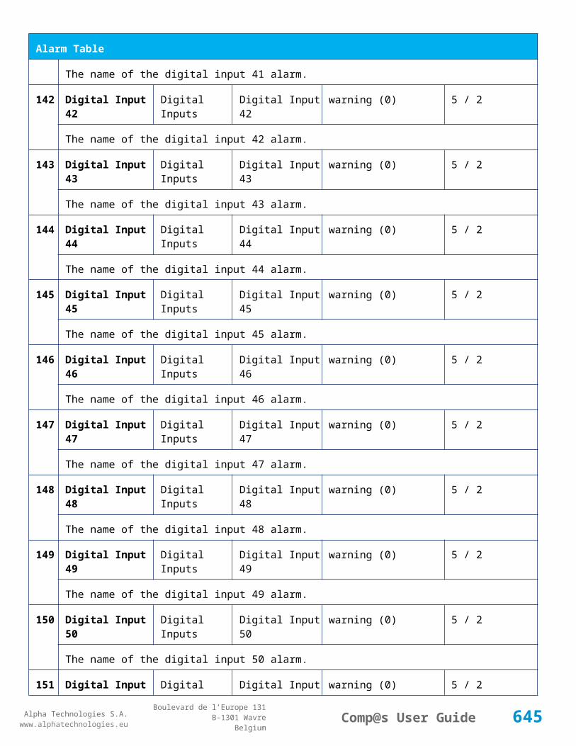
Alpha Technologies S.A.www.alphatechnologies.eu
Alpha Technologies S.A.www.alphatechnologies.eu
Comp@s User GuideBoulevard de l’Europe 131
B-1301 WavreBelgium
Revision 2.4.0.3 (4/04/2014) - SOFT 000031 39
* Inverter System: Improvement of the group and subgroup strings to have a more user friendly user interface. It is needed to reset default Name/Groups/Subgroups if there is already a saved configuration.
Revision 2.3.0.3 (31/03/2014) - SOFT 000031 38
* Improved Speed of Can Node type detection
+ SNMP - Possibility to modify the trap content, by sending additional site description.
+ SNMP - Developpers have the possibility to link data to alarms, to send them with the trap.
+ SNMP - Some data MIb entries described as Integer32 were transmitted as OctetString
+ TCP/Ip - New configuration element allows to define the Maximum Transmission Unit (MTU)
Revision 2.2.0.3 (12/03/2014) - SOFT 000031 37
- Web server redirection could loop if the default web page was forced to blank.
- Logout page link was pointing to old version of webpage
+ Suppport of Data Record on PLC Data
+ Suppport of $iif(condition, val if true, val if false) and $case(condition, val, condition2, val2, ...) functions in PLC equations
+ Dashboard support multiple dc systems
* Summary renamed to Reports
* Site --> in tab view, 'All' selection will also select the Description, Data, Alarm, Config and Control to understand the concept easily
- Renaming tool in the web interface was buggy because the page was self-refreshing while editing
* Schneider PM9C and IEM3150 RS485-devices are now seen as Energy Meter in the ETSI structure
* SNMP - Get of site data date and time was returning empty value. (Datetime format was not correctly supported)
- XML Post - Seconds between two XML Post was not correctly handeled)
* Better Factory Testing support for UCC (RS485 and RS232 are now automatically tested)
* When saving configuration, old element ids of live equipment are removed, this allows to clean if another type of ADIO has been installed, with different features
* New Control element 'Clean and Save XML User Configuration' allows to remove from configuration information about devices that are not present anymore.
645

Alpha Technologies S.A.www.alphatechnologies.eu
Alpha Technologies S.A.www.alphatechnologies.eu
Comp@s User GuideBoulevard de l’Europe 131
B-1301 WavreBelgium
Revision 2.1.0.3 (25/02/2014)
* Improved can drivers
* Minor changes
* Refactoring code for future improvements
Revision 2.0.0.3 (19/02/2014)
* FIRST RELEASE OF COMPAS '2.0.' - SUBJECT TO MINOR CHANGES
* New web interface - for old, go to index_old.html
* Major CPU and Memory Usage Optimisation
* Group and Subgroup allows filtering
* Support of SP0155/01 and SP0155/02
* Many other new features
Revision 0.126.0.4 (3/09/2013)
* Emulation - added configuration 54, UCC + 15 x Adio7
Revision 0.126.0.3 (23/08/2013) - SOFT 000031 36
* Sensors and Actuators - SAM0948 - Added hysteresis parameter on some alarms related to temperature, humidity and tilt
- CAN Driver is now compatible (was broken for 1 year) with first generation of compas board (blue card)
+ DC System - Support of scheduled battery test (based on CRON rules)
+ Support of wizards (first used to help defining the cron rule)
* Site: Drop-box for the configuration of the Time Zone
* XML Posting - Possibility to select which table must be sent on event. (description, alarm, data, configuration, control)
* ADIO - Support up to 16 ADIO board as sensors and actuators by default
Revision 0.125.0.3 (5/08/2013) - SOFT 000031 35
+ Remote Power Feeding: Support of new Module 60W/190V
- Set/Clear delays of alarms were divided by factor 2 because the alarm calculation was called twice.
646
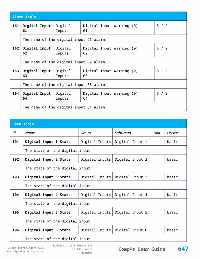
Alpha Technologies S.A.www.alphatechnologies.eu
Alpha Technologies S.A.www.alphatechnologies.eu
Comp@s User GuideBoulevard de l’Europe 131
B-1301 WavreBelgium
Revision 0.124.0.3 (28/06/2013)
+ Allow to set MCU specific configuration id. (Done in production, but allow to change in case of misconfigured MCU)
Revision 0.123.0.4 (13/06/2013) - SOFT 000031 34
* Table documentation generator for T2s (Inverter), Cordex Rectifiers and Cordex Dc System
Revision 0.123.0.3 (30/05/2013)
+ Remote Power Feeding : Support of new Module REC009
* XML Events and Armada: Alarm table was not sent completelly. Real time for alarm clear events is now ok.
* XML Events and Armada: Alarms are now correctly cleared for CAR rectifier, and sent also in realtime
* XML Events and Armada: After equipment creation, data sync is done for descriptions, alarms, data, events and configs
- Rack ACE102FALP - Module position issue with 2-slot distribution.
Revision 0.122.0.3 (9/04/2013) - SOFT 000031 33
- SNMP - Walk was not going anymore inside the dc system. Broken in 0.113.0.3
* SNMP - GlobalAlarmSeverityLevel of each equipment is now sent as an Integer (OctetString previously)
* SNMP - renamed Mitra to Atsa in Mib due to company name change.
* SNMP - Get next will now work from base oid iso.org.dod.internet
* SNMP - New oid entry 'xxxxGlobalAlarmSeverityTypeInt' for each equipment level. It is the same as the 'xxxxGlobalAlarmSeverityType' but as an integer (critical=4, major=3, minor=2, warning=1, none=0)
Revision 0.121.0.3 (21/03/2013) - SOFT 000031 32
+ Remote Power Feeding: Support of new 120W remote module.
- Cordex DC System: Solved transient dc mode changed to safe mode (bug introduced in 0.120.0.3
Revision 0.120.0.3 (8/03/2013) - SOFT 000031 31
* Cordex DC-System : Check that the voltage measurement has been refreshed recently, before regulating bus voltage.
647
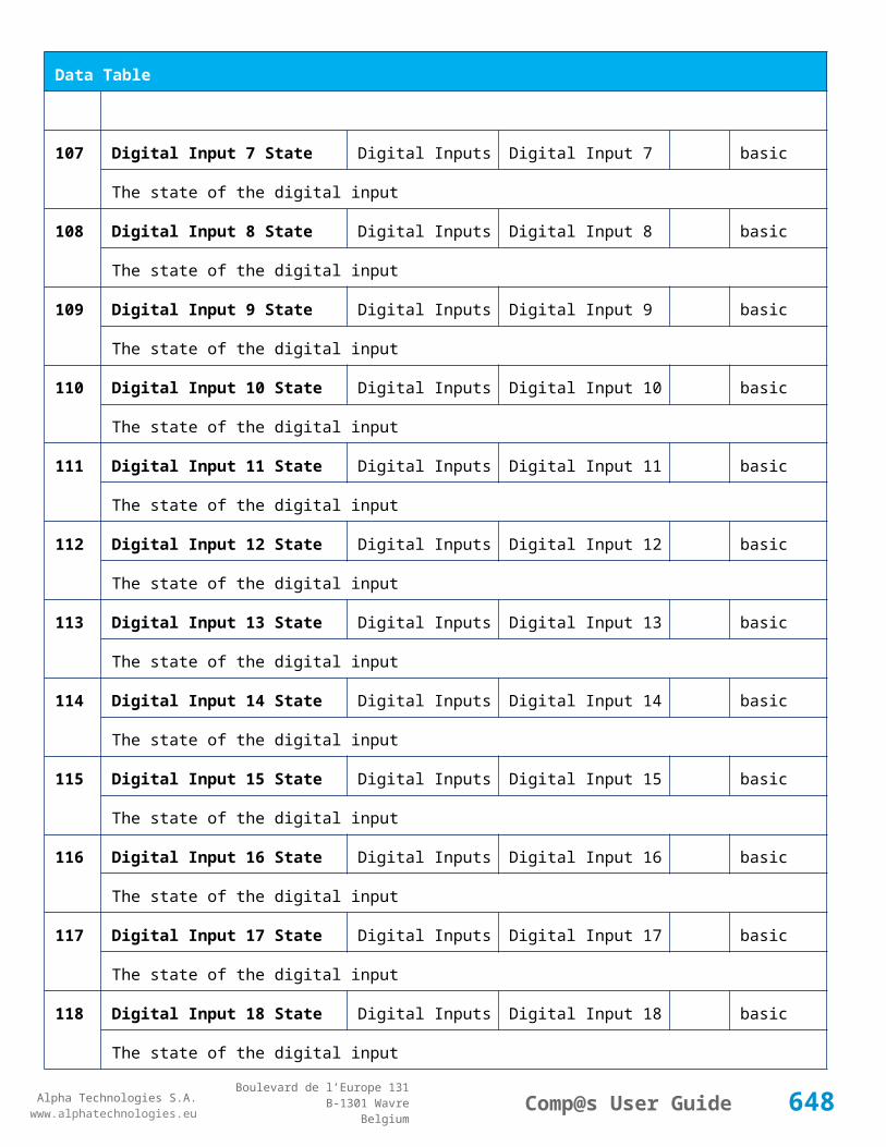
Alpha Technologies S.A.www.alphatechnologies.eu
Alpha Technologies S.A.www.alphatechnologies.eu
Comp@s User GuideBoulevard de l’Europe 131
B-1301 WavreBelgium
Revision 0.120.0.3 (8/03/2013) - SOFT 000031 31
* Cordex DC-System : Improved bus voltage regulation - reduce possible 100mV oscillation with ADIO10
* Inverter System - Optimisation of the bandwidth usage to allow more inverter systems (up to 20 T2S - More should be possible after validation)
* Inverter System - The system id is now saved with the CAN LSS information - allows to keep the same system order after a reboot
* Inverter System - Added a 1 minute delay before creating the inverters to avoid id transient.
Revision 0.119.0.3 (19/02/2013) - SOFT 000031 30
- Fix bug : element change event where not added to the correct equipment.
* Optimised version of the XML posting to Armada. Description, Data, Alarm, Config of the equipment are also sent.
* Remote Site - New control to copy address from the top site level (not the street).
* Remote Site - Address is copied from Top Site on first creation
* Up Converter System: Set/Clear Delay of the slot alarm increased to 15
* Default Post XML timeout changed to 100 seconds (was 2 seconds)
Revision 0.118.0.3 (23/01/2013) - SOFT 000031 29
- Fix bug introduced in 0.113.0.3 - If the site id is changed to anything starting with 1 like 11, 1021, etc. A stack overflow can happen at next reboot.
* Inverter system - Support of ETSI XML posting for real time events in Armada.
Revision 0.117.0.3 (21/01/2013) - SOFT 000031 28
- Fix bug introduced in 0.116.0.3 about the data record xml generation)
* Remote Site: Alarms list is updated depending on remote system (no fan alarm with 60W module for example)
* Remote Power System: Alarms are now grouped
+ Web Server: Display the Site Name as title of the web page
+ Display the Serial Number of Cordex Rectifier and Inverters in the left menu and on top of the element tables, display the reference for systems
648

Alpha Technologies S.A.www.alphatechnologies.eu
Alpha Technologies S.A.www.alphatechnologies.eu
Comp@s User GuideBoulevard de l’Europe 131
B-1301 WavreBelgium
Revision 0.116.0.3 (16/01/2013) - SOFT 000031 27
- Fix for relay control problem on ADIO10 (introduced in 0.115.0.3 changes)
* New control elements to calibrate voltage and currents on ADIO10
+ When the Site Name is configured, it is now the title of the web page. This needs a complete refresh of the web page (Ctrl-F5)
- Inverter system with T2S - Save to T2s is now more reliable
+ Inverter system with T2S - New control element to Turn On/Off all modules
* New parameters for site.xml, allowing to download only some resolutions of the records (day, hour, minute, second). By default, it retrieves only daily and hourly data records
* Finalization of the equalize feature for Cordex dc systems
+ Implementation of the periodic automatic battery test
Revision 0.115.0.3 (20/12/2012) - SOFT 000031 26
- Reworked relay boolean condition on ADIOs. Possibility to configure normal condition as 'Energized' or 'De-Energized'.
- Some Alarm Set delay were not reloaded correctly after reboot, lile the bus voltage sense failure
* Better support of T2S alarms
* Support of the T2S with Media Inverters
* Relay of Alarm 'Missing Rectifiers' can now be saved in MCU
Revision 0.114.0.7 (17/12/2012) - SOFT 000031 25
- Randomly, system could reboot at midnight during data records saving
- If events.xml was corrupted, the system could never start without deleting the file
* Better implementation of the data_record management. Thread safe and faster.
* Improvement of the DC bus voltage sense failure detection on Cordex
- Digital Input alarm logic was inverted on ADIO 7-8-9-10. If you are using it, care required when upgrading.
* More robust and faster startup
* Reboot improved to reply to request, delayed by 10 seconds to allow events to be sent to Arm@da
- After a 'Clear All Events' or 'Clear Events', the events were not rewritten to flash, and were present again at reboot. (broken in 0.113.0.3)
* Optimisation of the Web Server - Faster and uses less memory when files are posted
649
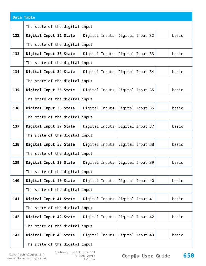
Alpha Technologies S.A.www.alphatechnologies.eu
Alpha Technologies S.A.www.alphatechnologies.eu
Comp@s User GuideBoulevard de l’Europe 131
B-1301 WavreBelgium
Revision 0.114.0.7 (17/12/2012) - SOFT 000031 25
* Better support of zip files generation (site.xml.zip). The files are now fully compliant (before, it was a compressed stream)
- PLC functions without arguments like $second() where broken unless used as $second(0)
Revision 0.113.0.3 (15/11/2012) - SOFT 000031 24
- SNMP walk was not working from top snmp node
+ Introduced group possibilities for the alarm table
+ Events are now automatically saved in a flat file : events_flat.xml. events.xml is converted on first boot.
+ Group is now loaded from configuration.xml for any element, allowing total customisation of name/group of elements
+ Possibility to rename Name and Group of any element from the web interface
+ Initial limited support of Cordex Converters
+ Support of energy meter IEM3150 on RS485 bus
* Improved RS485 modbus driver allowing different types of device on the same bus
* CEM03 - Remote Site can now have an id > 100 (up to 1000)
* Better implementation of the battery test for Cordex DC Systems
* SNMP - Improved MIB compliance - Some oid related name were too long
- SNMP - Traps content oids where shifted of 1
+ Cordex - Initial support of firmware upgrade
Revision 0.111.0.5 (12/10/2012)
- Corrected bugs in Cordex regulation, load sharing was wrong if canid did not match rectifier id
Revision 0.111.0.3 (31/07/2012) - SOFT 000031 23
+ Support of multiple Inverter System (T2S)
* Allow to limit the request of one CAN message at the time (for T2S)
+ Initial support of Alpha CXC over SNMP
650

Alpha Technologies S.A.www.alphatechnologies.eu
Alpha Technologies S.A.www.alphatechnologies.eu
Comp@s User GuideBoulevard de l’Europe 131
B-1301 WavreBelgium
Revision 0.110.0.3 (11/07/2012) - SOFT 000031 22
+ SNMP - Initial Support of monitoring of SNMP device like the Cordex CXC
+ Added possibilites to store a fix information about alarms
+ Support of 850W/1000W systems with embedded distribution.
+ Auto detection of the rectifier model for smart energy
+ Introduction of 'Absent' status for Cordex Rectifiers
+ New site control to remove absent equipments
+ New alarm at the site level to notify that the last configuration changes are not saved
* Remote Power Feeding - Added customer description element at the Remote Power Feeding System level
* Remote Power Feeding - Possiblitly to define the number of CEM03 by rack, in master/slave configuration --> up to 64 racks
* Better support of T2S inverter monitoring
* Better conversion from XML to XLS. (site.xml.xls) Can be used to generate a system user guide with the request : site.xml.xls?help=true&control=true
- CAN Driver - Randomly, a can message was corrupted because of an OS interrupt during SPI communication
- CAN Driver - The can driver was crashing when there was only one node on the bus and it was removed
- It was no possible to reset to empty the list of required node on the can bus (config Required CAN Bus Node IDs)
- Changed unit of Rectifier Cordex 'Service Time'(s->m) and 'Converted Energy'(KJ->kwh)
Revision 0.106.0.3 (22/03/2012) - SOFT 000031 21
* Changed the versioning method to allow modifications of release - 0.106.0.3 is the version after 0.1.0.104
Revision 0.1.0.104 (15/03/2012)
- CET Inverter were not detected anymore correctly -broken with 1.0.96
- Remote Powering System was not detected anymore correctly - broken with 1.0.96
* Remote Power Feeding system - New alarm is generated 'Configuration problem' when the slot is empty but there is a configuration
651

Alpha Technologies S.A.www.alphatechnologies.eu
Alpha Technologies S.A.www.alphatechnologies.eu
Comp@s User GuideBoulevard de l’Europe 131
B-1301 WavreBelgium
Revision 0.1.0.102 (23/02/2012)
* Modbus Slave – Do not reply anymore until modbus variable are updated on dc system creation. This avoids to send transiant 'fake' data
Revision 0.1.0.100 (15/02/2012)
- Modbus Slave – Socket was closed if the device id did not exist. Comp@s will now send a Modbus exception according to the standard.
- In remote Site in relation of a remote power feeding system, the latitude position parameter was not set correctly. (And changed the longitude).
Revision 0.1.0.98 (30/11/2011)
- In configurations with multiple independent racks, Modbus data were not correctly updated when multiple request on different racks were processed during one second.
Revision 0.1.0.96 (21/11/2011)
+ First official release supporting cordex 4kw rectifier, with new UCC
+ CanOpen Node definition is now managed to avoid any interference between new development and old qualified developments. (Thanks to better use of the polymorphism)
+ Complete support of LSS devices (Dynamic CanOpen node addressing for Cordex rectifiers)
+ Optimization of the CAN and CANOpen layer to reduce cpu usage. Great result achieved, CPU usage reduced by more than 20%. This allows better reactivity through the communications interfaces.
+ Web interface allows minimizing parts of the tables, by group.
Revision 0.1.0.88 (11/09/2011) - SOFT 000031 20
* Added debug features to analyze Modbus problems (connection timeout, new sockets, etc.)
* Support of rack 300W, with specific battery configuration possibilities with the help of the front button (electronic LVD)
Revision 0.1.0.86 (12/07/2011) - SOFT 000031 19
* The auto-save of records happening at midnight is now running in a separated thread to avoid any loss of communication and any problem in the main loop.
652

Alpha Technologies S.A.www.alphatechnologies.eu
Alpha Technologies S.A.www.alphatechnologies.eu
Comp@s User GuideBoulevard de l’Europe 131
B-1301 WavreBelgium
Revision 0.1.0.84 (21/06/2011)
* Support of up to 4 master racks on the modbus interface. (Previously 4). Modbus id 1-->4 are reserved for the 4 first DC Systems. If a request if sent to another id, the dc system 1 will reply.
Revision 0.1.0.82 (16/06/2011) - SOFT 000031 18
- Problem with reload of current limitation regulation parameter (because development test on going with hard coded values)
Revision 0.1.0.80 (16/06/2011)
+ Initial support for Alpha Cordex Rectifiers regulation of the dc system
+ Support of rack CAPTIN 300W
- Modbus Slave communication could fail when there are socket problems. (Cable disconnection, timeout, etc.) - This problems appeared with the new Ethernet drivers of BSP 3.9.
Revision 0.1.0.78 (30/05/2011) - SOFT 00031 17
+ Added support of PLC functions for es1 device.
Revision 0.1.0.76 (27/05/2011) - SOFT 00031 17
* RS485 communications was corrupted when interrupted by another task with higher priority.
Revision 0.1.0.74 (24/05/2011)
* New CAN driver – reduced CPU usage by up to 30%.
* New operating system – BSP 3.9
* New production tool – display instructions also in English
- BSP 3.9 new Ethernet driver is now synchronous to solve problems when communication is very high – Microsoft bug (Mobdus fast request in loop for instance)
Revision 0.1.0.72 (20/05/2011)
+ Added hidden function to clear registry (may be required after OS update)
653
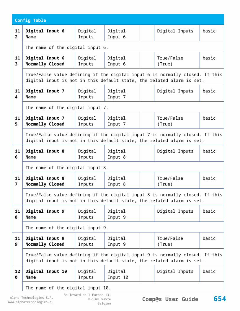
Alpha Technologies S.A.www.alphatechnologies.eu
Alpha Technologies S.A.www.alphatechnologies.eu
Comp@s User GuideBoulevard de l’Europe 131
B-1301 WavreBelgium
Revision 0.1.0.70 (10/05/2011)
+ Possibilities to auto save records in xml, download files from web interface, and delete files.
+ Possibilities to rename descriptions, alarms, data, configuration and control elements with the configuration.xml file
+ Initial support of independent LVD
+ Initial support of predefined configurations
Revision 0.1.0.68 (20/04/2011)
- Hardware watchdog – forgot to uncomment after test.
Revision 0.1.0.66 (20/04/2011)
+ Added zip extraction functions : Extract Zip File in user-upload
- Records of the energy system pulse counter were loaded twice with a PM9C device
Revision 0.1.0.64 (16/04/2011)
+ Support of remote upgrade of the operating system and boot loader. (very advanced, necessary only for specific new functionalities)
+ Added data at site level: ‘CPU Percentage Usage’ and ‘Free Flash Memory Space’, with associated records.
+ Added description at site level : Operating System Revision
+ Support for the http post of files
+ New web page accessible from “Advanced” : manage_files.html
+ The exe file are analysed to retrieve the software revision
+ The zip files are analysed to discover the compressed file. (Only one file by zip is allowed to avoid unmanageable folder structure)
+ Added advanced functions in site/control: (used by the manage files web-page) (Flash Binary, Download File From Url, Delete User Uploaded File, Move User Uploaded File
Revision 0.1.0.62 (10/04/2011)
* Support of snmp get bulk
* Added possibilities to rename all the variable names. Change the name in the xml configuration file and the related id will be updated on start. (for description, data, alarm, config and control)
654

Alpha Technologies S.A.www.alphatechnologies.eu
Alpha Technologies S.A.www.alphatechnologies.eu
Comp@s User GuideBoulevard de l’Europe 131
B-1301 WavreBelgium
Revision 0.1.0.62 (10/04/2011)
- Snmp walk was buggy with some PLC data configurations
Revision 0.1.0.60 (6/04/2011)
+ Added configuration parameters to force the Ethernet mode (10-100Mb – Half-full duplex. (Require OS 3.5 at least)
+ Initial support of snmp get bulk
+ Improved support of default snmp oid (1.3.6.1.2.1.1.4,5,6,9.1.3
Revision 0.1.0.58 (5/04/2011)
- Rewrite of the Modbus RTU Master driver to solve random crash after a few days (windows serial driver bug)
Revision 0.1.0.56 (9/03/2011)
+ Support of additional extensions for Opera Net Project (sensors and actuators)
+ Support of PM9C energy counter over RS485
Revision 0.1.0.54 (21/02/2011)
+ Initial support of Alpha rectifiers
+ CANOpen LSS master implementation
* Added PLC functions to get site level info
Revision 0.1.0.52 (6/01/2011)
+ Initial support of RS485 Modbus Master
* Added entry 151 in Modbus
Revision 0.1.0.50 (29/10/2010) - SOFT 000031 16
* Improved support of 300W rack family
655

Alpha Technologies S.A.www.alphatechnologies.eu
Alpha Technologies S.A.www.alphatechnologies.eu
Comp@s User GuideBoulevard de l’Europe 131
B-1301 WavreBelgium
Revision 0.1.0.48 (18/10/2010)
+ Initial support of 300W rack family
Revision 0.1.0.46 (29/06/2010)
* Support of 3 dc-system over Modbus interface
Revision 0.1.0.44 (3/06/2010)
* Added concept of dc system and rectifier models (for smart functions)
Revision 0.1.0.42 (20/04/2010)
* Improved support of CET inverters
- Bug correction of removed rectifiers if not declared in large systems
Revision 0.1.0.40 (21/01/2010) - SOFT 000031 14
+ Minor support of CET inverters
* Change of OS, minor security updates (BSP 0.5)
- Correction of Ethernet bug with HUB (drivers was switching of the Ethernet devices if disconnected from hub)
Revision 0.1.0.38 (19/01/2010)
* Review of the logic for ac fail conditions
Revision 0.1.0.34 (24/11/2009)
* Increased reliability of the CAN bootloader reset algorithm
Revision 0.1.0.32 (19/11/2009)
+ Support of large system with CAN regulation (up to 90x2600W rectifiers)
Revision 0.1.0.30 (19/10/2009)
+ Support of MCU0548
656

Alpha Technologies S.A.www.alphatechnologies.eu
Alpha Technologies S.A.www.alphatechnologies.eu
Comp@s User GuideBoulevard de l’Europe 131
B-1301 WavreBelgium
Revision 0.1.0.30 (19/10/2009)
* Changed remote system type name (3x120w, etc)
Revision 0.1.0.28 (19/10/2009) - SOFT 000031 13
* Data records are now stored in XML, and are auto-saved
* Data records are reloaded on startup
* Optimization of the XML file generation
* Support of compressed XML file in ZIP (xml.zip)
* Full support of SNMP V3 traps
* Added support of energy consumption measurement at the energy system level (pulse counter)
* Added cold start type event (to be able to rediscover the site in XML after power outage – according to ES 202 336 standard change request)
- Modification of one registry parameter, to disable the “auto sense mode” of Ethernet, which was disabling the Ethernet when connected to a hub.
Revision 0.1.0.26 (16/06/2009)
* Added support for SNMP V3, with updated libraries
* Added support of remote power feeding systems
* Compilation in VS2008
* Web page layout changed from Cherokee to Mitra E&I
* Updated version of operation system, with latest windows update and latest drivers. (in production with SOFT 000031 12)
- Bug in the data record queue for last days and last hours records.
Revision 0.1.0.24 (27/03/2009)
* Added support of MCU3048M6
* Optimization of the CAN driver
Revision 0.1.0.22 (1/10/2008) - SOFT 000031 12
* (Updated OS drivers on 25 March 2009, because of new booloader on Comp@s card.)
657

Alpha Technologies S.A.www.alphatechnologies.eu
Alpha Technologies S.A.www.alphatechnologies.eu
Comp@s User GuideBoulevard de l’Europe 131
B-1301 WavreBelgium
Revision 0.1.0.22 (1/10/2008) - SOFT 000031 12
- DC System Refresh Task buggy if only one rectifier in current limitation --> nothing was refreshed
Revision 0.1.0.20 (1/09/2008) - SOFT 000031 11
* With the Modbus interface, the currents are now given in 0.1A as unit.
* Support of XXXXconfigurationYYYY.xml files in Factory folder. This allows naming easily the configuration files.
- With a very low probability, the application could crash during startup. (It restarted correctly after 5 minutes thanks to the watchdog).
Revision 0.1.0.18 (1/08/2008)
* New configuration parameter: XML Event Posting To Secondary Only If Primary Failure (Set to True by default). This allows sending XML events to the redundant server only if the first fails.
* New configuration parameter: XML Heartbeat Time (minute): Define the time in minutes between two heartbeats. It is now possible to request the monitoring to send heartbeat in order to check the communication availability. This XML heartbeat looks like: <site id="1" status="alarms" severity_type="major" severity_level="6" /> Note that the same behavior with primary/secondary server is used.
* Modbus compatibility improvements
* No current limitation by default (1000A by default, must be set correctly).
* Functional battery test is configured (1000A as discharge current, 0% of discharge capacity, duration of 10 minutes). --> Must me correctly configured with the battery parameters for reliable battery test.
* PLC license is now included in the Asset license.
Revision 0.1.0.16 (1/07/2008)
* New Modbus license option
* MCU30110 support
* Comp@s Display Module Support (CDM)
* CSV Log file of battery tests can be downloaded from web interface
- Firmware boot loading may fail under some circumstances
- The web server function ‘ProcessXML.cgi’ processed only site level configuration
- On system reboot, for alarm related events, the datetime is not parsed correctly
- On system reboot, the set delay of the alarms was replaced by the clear delay.
658

Alpha Technologies S.A.www.alphatechnologies.eu
Alpha Technologies S.A.www.alphatechnologies.eu
Comp@s User GuideBoulevard de l’Europe 131
B-1301 WavreBelgium
Revision 0.1.0.14 (28/05/2008) - SOFT 000031 10
* Web interface compatible with older browser (Internet Explorer 6)
* Web page generation 4x faster
+ Time Zone support
+ Daylight Saving Time
- The system time could be badly loaded during booting
- XML event posting locked when server answers badly
- Possible web server crash if socket not correctly closed
Revision 0.1.0.12 (14/02/2008) - SOFT 000031 09
+ Support of multi-language web interface
+ Support of 2x6x1800W DC systems (with 2 MCU1848)
+ PLC module added (customization of data and alarm)
- The severy_type attribute in the XML syntax was not correctly encoded
Revision 0.1.0.8 (6/01/2008) - SOFT 000031 06
* The default value of the minimal number of rectifier is 0, to avoid alarm by default.
+ Support of 3U rack with up to 8 CAR0948TN.
* Improvement of the logic of the site access control with SAM0948. Any digital input can be associated with a door.
- DC system alarm relay configuration was not saved if configured on ‘0’.
- Problem with reload of customized alarm related to the digital inputs of the dc system.
Revision 0.1.0.2 (1/11/2007)
+ Support of MCU1848
* Added alarm “Missing Rectifiers” at DC system level
* Added configuration parameter “Minimal number of rectifier” at DC system level
- Configuration of the SAM0948 was not kept after system reboot
659

Alpha Technologies S.A.www.alphatechnologies.eu
Alpha Technologies S.A.www.alphatechnologies.eu
Comp@s User GuideBoulevard de l’Europe 131
B-1301 WavreBelgium
Revision 0.1.0.1 (1/06/2007) - SOFT 000031 01
+ First official version
+ Support of MCU0948
+ Support of CAR0948TN
+ Support of SAM0948
660

Alpha Technologies S.A.www.alphatechnologies.eu
Alpha Technologies S.A.www.alphatechnologies.eu
Comp@s User GuideBoulevard de l’Europe 131
B-1301 WavreBelgium
11 EMULATION CAPABILITIES
On demand, we can provide an emulation program of the real monitoring application. This emulation program can run on any personal computer running Windows. Thanks to this last, you can develop and test the integration of our monitoring platform inside your network management application.
What is the Comp@s emulator?
What are the requirements?
How to run the emulator?
How to use the emulator?
Simulating a network of Comp@s system
Where can I get the emulator?
Remarks.
11.1 What is the Comp@s emulator?
This is software which allows the simulation of the Comp@s monitoring, with some DC Systems and extension cards.
By default, the emulator simulates the presence of 2 sub-shelves 4x850W, with some rectifiers. Also an AC failure alarm appears and disappears, generating events and modifications of element status. An extension card with some sensors and access control is also simulated.
With the emulator, you can develop and test the integration of our monitoring platform inside your network management application.
11.2 What are the requirements?
Any personal computer running Windows 2000, XP or later.
You need the Microsoft .NET Framework 2.0 installed on your computer. This is freely available through Microsoft website or Windows Update.
11.3 How to run the emulator?
When you execute the provided “Compas_Emulator.exe”, it is possible that the windows firewall ask to open port 80 and/or 161. This is necessary in order to run the web server and the SNMP agent.
To stop the emulator, you just have to close the opened shell window.
661
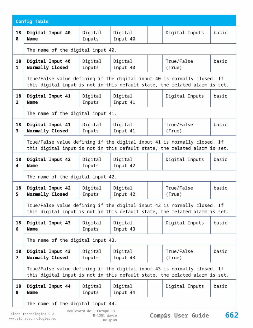
Alpha Technologies S.A.www.alphatechnologies.eu
Alpha Technologies S.A.www.alphatechnologies.eu
Comp@s User GuideBoulevard de l’Europe 131
B-1301 WavreBelgium
11.4 How to use the emulator?
Start the Compas_Emulator.exe application
Testing the Web Server :
a. Start you favorite web browser (Firefox 2.x or Internet Explorer 7.x)
b. Browse to http://127.0.0.1:8080/ or http://localhost:8080/
c. You are asked for a login/password which is admin/compas by default
d. Please refer to 5.3. to use the Web Interface
Testing SNMP :
a. You need a SNMP MIB browser (see The Comp@s SNMP Agent)
b. The MIB can be downloaded through the web interface
c. You can test the SNMP agent at the ip 127.0.0.1 (port 162)
d. Read Community is admin:compas by default
e. Write Community is admin:compas by default
f. Please refer to SNMP Agent for more information.
11.5 Simulating a network of Comp@s system
If you want to simulate multiple sites, you can start the emulator on different port. For example, to execute an instance on port 85, execute “Compas_Emulator 85”.
11.6 Where can I get the emulator?
Please contact your vendor.
11.7 Remarks
This emulator is just an introduction to the different interfaces
It is not possible to have a real overview of all the Comp@s functionalities.
This emulator is not deeply tested as the real embedded monitoring, bugs may be present, please tell us.
By default, the emulator opens the port 8080 for the web server. If you are already running a web server on your computer, you will need to start the emulator on another port.
662

Alpha Technologies S.A.www.alphatechnologies.eu
Alpha Technologies S.A.www.alphatechnologies.eu
Comp@s User GuideBoulevard de l’Europe 131
B-1301 WavreBelgium
The FTP Server is not emulated.
663
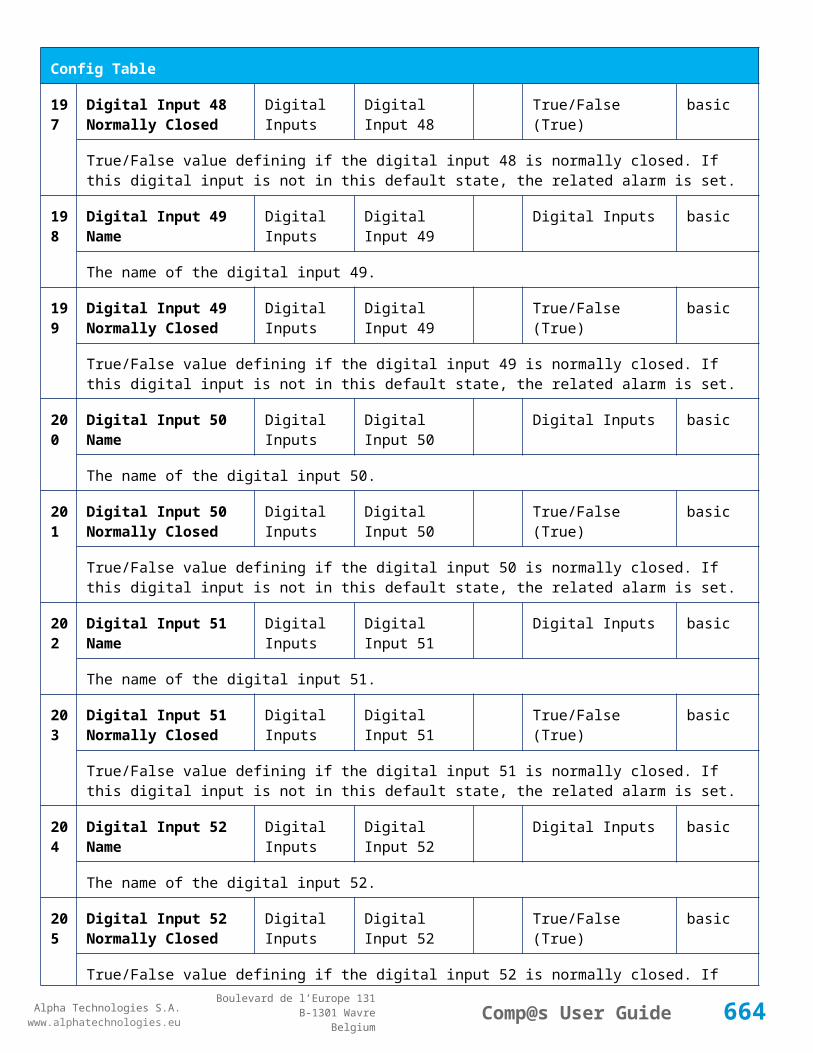
Alpha Technologies S.A.www.alphatechnologies.eu
Alpha Technologies S.A.www.alphatechnologies.eu
Comp@s User GuideBoulevard de l’Europe 131
B-1301 WavreBelgium
1 2 F R E Q U E N T L Y A S K E D Q U E S T I O N S
USB Connection Troubles
12.1 USB Connection Troubles
Q : I can browse Comp@s flash disk but I cannot open the Comp@s webpage in my web browser.
A: This kind of troubles usually occurs when software on your computer is listening on port 80. To solve, check if your port 80 is listening and then shutdown the application listening on it or kill it. This trouble appears with IIS, Skype, …
To do that:
Open cmd prompt and type the following command:
Administrator Command Prompt
Focus on line: TCP 0.0.0.0:80 0.0.0.0 LISTENING 4. You see on the first line something is listening on port 80 and it’s the pid number 4 which is listening.
Open task manager and check if you can locate pid number. If you cannot see pid column, click “View -> Select columns” and check checkbox “PID Process identifier”. Select the pid process and click on “End Process” button:
664

Alpha Technologies S.A.www.alphatechnologies.eu
Alpha Technologies S.A.www.alphatechnologies.eu
Comp@s User GuideBoulevard de l’Europe 131
B-1301 WavreBelgium
Windows Task Manager
If you cannot find your pid, open cmd prompt and type “c:\windows\system32\telnet 127.0.0.1 80”. Telnet connect to the port. A black screen occurs and type “Echo”. If the telnet command is not recognized, type “pkgmgr /iu:TelnetClient “, and retry.
In my example case, I type echo in the black screen and I have the following message. I see it’s Microsoft HTTP Server, so I shutdown IIS:
ISS Shutdown
And finally, I retype “netstat –ano | findstr 0.0:80” and I see nothing is listening on port 80. So I can now connect to Comp@s WebPage.
665

Alpha Technologies S.A.www.alphatechnologies.eu
Alpha Technologies S.A.www.alphatechnologies.eu
Comp@s User GuideBoulevard de l’Europe 131
B-1301 WavreBelgium
Q : After plug in, the usb cable in my computer, i see the device is not recognized and the driver could not successfully installed.
A: You have to take care of using multiple mobile devices at the same time. For exemple, it’s not possible to connect to compas if you have connected your mobile phone to the computer using bluetooth and so on.
Q: On my web brower, I see access denied to 127.0.0.1 .
A: If you are connected to LAN, and the network uses proxy or firewall, it is possible the connection to 127.0.0.1 is blocked.
Try to unplug your Ethernet cable or switch off your wifi connection, and try again. It’s possible to add a special rule in browser connection settings to bypass proxy/firewall when connection to 127.0.0.1 occurs.
For this example, if you use IE, go to options -> Connections -> Lan Settings and check “Bypass proxy server for local address”:
Bypass Proxy Server for Local Address
666
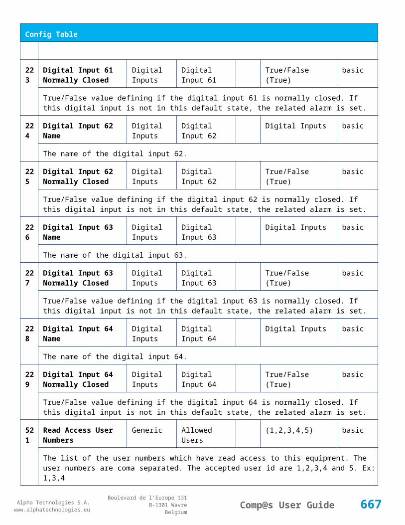
Alpha Technologies S.A.www.alphatechnologies.eu
Alpha Technologies S.A.www.alphatechnologies.eu
Comp@s User GuideBoulevard de l’Europe 131
B-1301 WavreBelgium
13 SUPPORT
Do not hesitate to contact us in case of questions, problems, suggestions, etc. We want to be your partner in a successful network management.
667