general information - ishik – sulaimani · general information ... shear force, and bending...
TRANSCRIPT

Mechanics of Material 10/7/2017
1
General Information
Assistant Lecturer: Asmaa Ab. Mustafa
Email : [email protected]
Department : Civil Engineering
Course Title : Mechanics of Material I
Code : CE 211
Credit : 3
Office Hour : Sunday 14:00 – 16:00
or by appointment
Website : http://www.sul.ishik.edu.iq/asmaa-abdulmajeed
Grade : 2nd
Year : 2017 - 2018
1
Ish
ik U
niv
ersity
- Su
laim
an
i
Assis
tan
t Le
ctu
rer - A
sm
aa
Ab
.
Mech
an
ics o
f Ma
teria
ls
Required Textbook :
*R.C. Hibbeler – “Mechanics of Materials”,8th
Edition, Prentice Hall, Upper Saddle River, New
Jersey, 2010
Additional References :
*F.P. Beer, E. R. Johnston, J.T. DeWolf – “Mechanics of Materials”, 4th Edition, McGraw- Hill, New York, 2006
*James M. Gere, “Mechanics of Materials”, 6th Edition, Professor Emeritus, Stanford University, 2008.
*A.P. Boresi, R.J. Schmidt – “Advanced Mechanics of Materials”, 6th Edition, John Wiley & Sons, New York, 2003.
*R.D. Cook and W.C. Young - “Advanced Mechanics of Materials”, 2nd Ed. Prentice-Hall, Upper Saddle River, New Jersey, 1999.
*J.R. Barber - "Intermediate Mechanics of Materials" McGraw-Hill, New York, 2001.
2
Ish
ik U
niv
ersity
- Su
laim
an
i
Assis
tan
t Le
ctu
rer - A
sm
aa
Ab
.
Mech
an
ics o
f Ma
teria
ls

Mechanics of Material 10/7/2017
2
Evaluation Criteria :
Weekly Quizzes : 10%
Assignments : 10%
Bonus Quizzes : 5%
Project : 5%
Mid-term Exam : 30%
Final Exam : 40%
Assignments :
Approximately (10) homework assignments will be given
during the term. These assignments are very important. Their
purpose is to promote your understanding of the course
material, and to provide needed practice with example
problems that are too lengthy to discuss in class. It is your
responsibility to complete each homework assignment within
one week of distribution. 3
Ish
ik U
niv
ersity
- Su
laim
an
i
Assis
tan
t Le
ctu
rer - A
sm
aa
Ab
.
Mech
an
ics o
f Ma
teria
ls
Weekly Quizzes :
Except for the week corresponding to the midterm, weekly
quizzes will be given once per week, during the first
fifteen minutes of lecture. In the Quiz, you will be
expected to solve one of the questions from the previous
week’s subject (possibly with slight alterations in the
numbers). The weekly quizzes will be completely closed
book although calculators will be allowed.
Midterms and Exam :
One midterms will be scheduled in addition to the final
examination. Midterm and the final exam will be closed
book. You will also be allowed to use a non-
communicating calculator.
4
Ish
ik U
niv
ersity
- Su
laim
an
i
Assis
tan
t Le
ctu
rer - A
sm
aa
Ab
.
Mech
an
ics o
f Ma
teria
ls

Mechanics of Material 10/7/2017
3
Prerequisites :
Must have passed Engineering Mechanics: Statics
5
Ish
ik U
niv
ersity
- Su
laim
an
i
Assis
tan
t Le
ctu
rer - A
sm
aa
Ab
.
Mech
an
ics o
f Ma
teria
ls
Class Attendance and Absences :
Students are strongly encouraged to attend class since some
course material may only appear in lectures. Students that
miss class are responsible for obtaining class notes from a
classmate. Also students whom their absent percentage pass
20% will fail in that course automatically.
Conduct :
Students are expected to arrive at lectures on time, and to
conduct themselves during class in a professional and
respectful manner that is not disruptive to others. Please put
your cell phone in silent mode before coming to class, quiz
or exam.
6
Ish
ik U
niv
ersity
- Su
laim
an
i
Assis
tan
t Le
ctu
rer - A
sm
aa
Ab
.
Mech
an
ics o
f Ma
teria
ls

Mechanics of Material 10/7/2017
4
Content :
This course is an introduction to the concepts of stress,
deformation and strain in solid materials. Basic
relationships between loads, stresses, and deflections of
structural and machine elements such as rods, shafts and
beams are developed. The load carrying capacity of these
elements under tension, compression, torsion, bending and
shear forces are considered.
Course Format :
There will be daily lectures. Your active participation is
essential in making the class a success. Read the material
before class and come equipped with questions.
7
Ish
ik U
niv
ersity
- Su
laim
an
i
Assis
tan
t Le
ctu
rer - A
sm
aa
Ab
.
Mech
an
ics o
f Ma
teria
ls
8
Ish
ik U
niv
ersity
- Su
laim
an
i
Assis
tan
t Le
ctu
rer - A
sm
aa
Ab
.
Mech
an
ics o
f Ma
teria
ls
Statics – Equilibrium Analysis of particles and bodies
Dynamics – Accelerated motion of particles and bodies
1.Engineering Mechanics
2.Fundamentals Concepts
Basic Quantities
Length, Mass, Time, Force
Units of Measurement
m, kg, s, N… (SI, Int. System of Units)
- Dimensional Homogeneity
- Significant Figures

Mechanics of Material 10/7/2017
5
3. Static Analysis
• Force and Equilibrium
• Force System Resultants
• Structural Analysis
• Internal forces
• Friction
• Centroid and Moments of Inertia
• Virtual Work and Stability
9
Ish
ik U
niv
ersity
- Su
laim
an
i
Assis
tan
t Le
ctu
rer - A
sm
aa
Ab
.
Mech
an
ics o
f Ma
teria
ls
10
Ish
ik U
niv
ersity
- Su
laim
an
i
Assis
tan
t Le
ctu
rer - A
sm
aa
Ab
.
Mech
an
ics o
f Ma
teria
ls

Mechanics of Material 10/7/2017
6
Chapter -1- STRESS
Outlines of this chapter :
1) Chapter Objectives
2) Introduction
3) Equilibrium of a Deformable Body
4) Stress
5) Average Normal Stress in an Axially Loaded Bar
6) Average Shear Stress
7) Allowable Stress
8) Design of Simple Connection
11
Ish
ik U
niv
ersity
- Su
laim
an
i
Assis
tan
t Le
ctu
rer - A
sm
aa
Ab
.
Mech
an
ics o
f Ma
teria
ls
UNITS:
S.I. units
will
be used
mostly,
but student
should
also know
Inch system
as well.
12
Ish
ik U
niv
ersity
- Su
laim
an
i
Assis
tan
t Le
ctu
rer - A
sm
aa
Ab
.
Mech
an
ics o
f Ma
teria
ls

Mechanics of Material 10/7/2017
7
13
Ish
ik U
niv
ersity
- Su
laim
an
i
Assis
tan
t Le
ctu
rer - A
sm
aa
Ab
.
Mech
an
ics o
f Ma
teria
ls
14
Ish
ik U
niv
ersity
- Su
laim
an
i
Assis
tan
t Le
ctu
rer - A
sm
aa
Ab
.
Mech
an
ics o
f Ma
teria
ls
1) Chapter Objectives
In this chapter we will review some of the important
principles of statics and show how they are used to
determine the internal resultant loadings in a body.
Afterwards the concepts of normal and shear stress will be
introduced, and specific applications of the analysis and
design of members subjected to an axial load or direct
shear will be discussed.
Mechanics of Material 10/7/2017
8
2) Introduction
Mechanics of materials is a branch of mechanics that studies the
internal effects of stress and strain in a solid body that is subjected
to an external loading. Stress is associated with the strength of the
material from which the body is made, while strain is a measure
of the deformation of the body. In addition to this, mechanics of
materials includes the study of the body’s stability when a body
such as a column is subjected to compressive loading. A thorough
understanding of the fundamentals of this subject is of vital
importance because many of the formulas and rules of design
cited in engineering codes are based upon the principles of this
subject. 15
Ish
ik U
niv
ersity
- Su
laim
an
i
Assis
tan
t Le
ctu
rer - A
sm
aa
Ab
.
Mech
an
ics o
f Ma
teria
ls
3) Equilibrium of a Deformable Body
16
Ish
ik U
niv
ersity
- Su
laim
an
i
Assis
tan
t Le
ctu
rer - A
sm
aa
Ab
.
Mech
an
ics o
f Ma
teria
ls
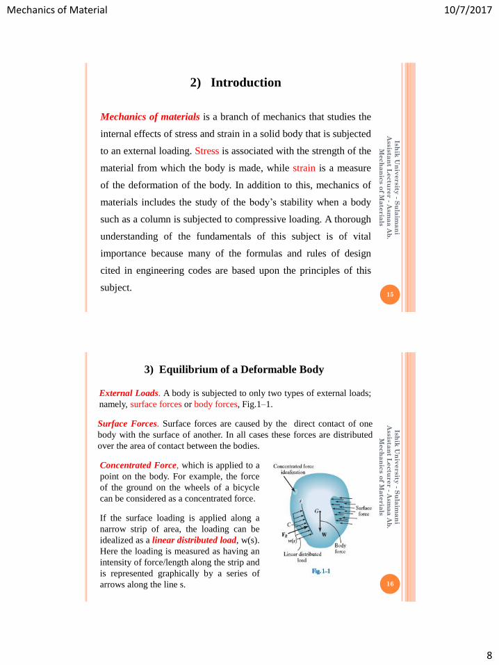
External Loads. A body is subjected to only two types of external loads;
namely, surface forces or body forces, Fig.1–1.
Surface Forces. Surface forces are caused by the direct contact of one
body with the surface of another. In all cases these forces are distributed
over the area of contact between the bodies.
Concentrated Force, which is applied to a
point on the body. For example, the force
of the ground on the wheels of a bicycle
can be considered as a concentrated force.
If the surface loading is applied along a
narrow strip of area, the loading can be
idealized as a linear distributed load, w(s).
Here the loading is measured as having an
intensity of force/length along the strip and
is represented graphically by a series of
arrows along the line s.

Mechanics of Material 10/7/2017
9
Support Reactions. The surface forces that develop at the
supports or points of contact between bodies are called
reactions.
17
Ish
ik U
niv
ersity
- Su
laim
an
i
Assis
tan
t Le
ctu
rer - A
sm
aa
Ab
.
Mech
an
ics o
f Ma
teria
ls
Equations of Equilibrium. Equilibrium of a body requires both a
balance of forces, to prevent the body from translating or having
accelerated motion along a straight or curved path, and a balance
of moments, to prevent the body from rotating. These conditions
can be expressed mathematically by two vector equations.
18
Ish
ik U
niv
ersity
- Su
laim
an
i
Assis
tan
t Le
ctu
rer - A
sm
aa
Ab
.
Mech
an
ics o
f Ma
teria
ls

Mechanics of Material 10/7/2017
10
Ish
ik U
niv
ersity
- Su
laim
an
i
Assis
tan
t Le
ctu
rer - A
sm
aa
Ab
.
Mech
an
ics o
f Ma
teria
ls
19
Internal Resultant Loadings
In mechanics of materials, statics is primarily used to determine the
resultant loadings that act within a body.
• Normal force, N; This force acts perpendicular to the area. It is
developed whenever the external loads tend to push or pull on
the two segments of the body.
• Shear force, V; The shear force lies in the plane of the area and
it is developed when the external loads tend to cause the two
segments of the body to slide over one another.
• Torsional moment or torque, T; This effect is developed when
the external loads tend to twist one segment of the body with
respect to the other about an axis perpendicular to the area.
• Bending moment, M; The bending moment is caused by the
external loads that tend to bend the body about an axis lying
within the plane of the area.
Ish
ik U
niv
ersity
- Su
laim
an
i
Assis
tan
t Le
ctu
rer - A
sm
aa
Ab
.
Mech
an
ics o
f Ma
teria
ls
20
Point O is most often chosen at the centroid of the sectioned area.

Mechanics of Material 10/7/2017
11
Example 1.1
Determine the resultant internal loadings acting on the cross section at
C of the cantilevered beam shown in Fig.1–4a.
21
Ish
ik U
niv
ersity
- Su
laim
an
i
Assis
tan
t Le
ctu
rer - A
sm
aa
Ab
.
Mech
an
ics o
f Ma
teria
ls
22
Ish
ik U
niv
ersity
- Su
laim
an
i
Assis
tan
t Le
ctu
rer - A
sm
aa
Ab
.
Mech
an
ics o
f Ma
teria
ls

Mechanics of Material 10/7/2017
12
23
Ish
ik U
niv
ersity
- Su
laim
an
i
Assis
tan
t Le
ctu
rer - A
sm
aa
Ab
.
Mech
an
ics o
f Ma
teria
ls
Example 1.2
Determine the resultant internal loadings acting on the cross
section at C of the machine shaft shown in Fig. 1–5a.The shaft is
supported by journal bearings at A and B, which only exert
vertical forces on the shaft.
24
Ish
ik U
niv
ersity
- Su
laim
an
i
Assis
tan
t Le
ctu
rer - A
sm
aa
Ab
.
Mech
an
ics o
f Ma
teria
ls

Mechanics of Material 10/7/2017
13
Assignment 1.1
25
Ish
ik U
niv
ersity
- Su
laim
an
i
Assis
tan
t Le
ctu
rer - A
sm
aa
Ab
.
Mech
an
ics o
f Ma
teria
ls
Determine the internal normal force, shear force, and bending
moment at point C in the beam.
Assignment 1.2
Determine the internal normal force, shear force, and bending
moment at point C in the beam.
26
Ish
ik U
niv
ersity
- Su
laim
an
i
Assis
tan
t Le
ctu
rer - A
sm
aa
Ab
.
Mech
an
ics o
f Ma
teria
ls

Mechanics of Material 10/7/2017
14
4) Stress
Normal Stress. The intensity of the force acting normal to is defined as
the normal stress, σ (sigma).
If the normal force or stress “pulls” on ΔA as shown in Fig. 1–10a, it is
referred to as tensile stress, whereas if it “pushes” on ΔA it is called compressive stress.
Shear Stress. The intensity of force acting tangent to is called the shear
stress, τ (tau).
Units. Since stress represents a force per unit area, in the International Standard or SI system, the magnitudes of both normal and shear stress are specified in the basic units of newton per square meter (N/m2) .This unit, called a Pascal (1Pa=1N/m2) is rather small, and in engineering work prefixes such as kilo-(103) symbolized by k, mega- (106) symbolized by M, or giga- (109) symbolized by G, are used to represent larger, more realistic values of stress.* Likewise, in the Foot-Pound-Second system of units, engineers usually express stress in pounds per square inch (psi) or kilo-pounds per square inch (ksi), where 1kilo-pound(kip) = 1000 lb. 27
Ish
ik U
niv
ersity
- Su
laim
an
i
Assis
tan
t Le
ctu
rer - A
sm
aa
Ab
.
Mech
an
ics o
f Ma
teria
ls
Sometimes stress is expressed in units N/mm2.
Where 1mm=10-3 m.
However, in the SI system, prefixes are not allowed in the
denominator of a fraction and therefore it is better to use
the equivalent
1 N/mm2 = 1 MN/m2 = 1 MPa.
28
Ish
ik U
niv
ersity
- Su
laim
an
i
Assis
tan
t Le
ctu
rer - A
sm
aa
Ab
.
Mech
an
ics o
f Ma
teria
ls

Mechanics of Material 10/7/2017
15
29
Ish
ik U
niv
ersity
- Su
laim
an
i
Assis
tan
t Le
ctu
rer - A
sm
aa
Ab
.
Mech
an
ics o
f Ma
teria
ls
5) Average Normal Stress in an Axially Loaded Bar
Ish
ik U
niv
ersity
- Su
laim
an
i
Assis
tan
t Le
ctu
rer - A
sm
aa
Ab
.
Mech
an
ics o
f Ma
teria
ls
30
Here :
σ : Average normal stress at any point on the cross-sectional area.
P : internal resultant normal force, which acts through the centroid of
the cross-sectional area. P is determined using the method of sections
and the equations of equilibrium.
A : Cross-sectional area of the bar where is determined.

Mechanics of Material 10/7/2017
16
Ish
ik U
niv
ersity
- Su
laim
an
i
Assis
tan
t Le
ctu
rer - A
sm
aa
Ab
.
Mech
an
ics o
f Ma
teria
ls
31
Ish
ik U
niv
ersity
- Su
laim
an
i
Assis
tan
t Le
ctu
rer - A
sm
aa
Ab
.
Mech
an
ics o
f Ma
teria
ls
32

Mechanics of Material 10/7/2017
17
The bar in Fig. 1–16a has a constant width of 35 mm and a
thickness of 10 mm. Determine the maximum average
normal stress in the bar when it is subjected to the loading
shown:
Ish
ik U
niv
ersity
- Su
laim
an
i
Assis
tan
t Le
ctu
rer - A
sm
aa
Ab
.
Mech
an
ics o
f Ma
teria
ls
33
Example 1.3
Ish
ik U
niv
ersity
- Su
laim
an
i
Assis
tan
t Le
ctu
rer - A
sm
aa
Ab
.
Mech
an
ics o
f Ma
teria
ls
34

Mechanics of Material 10/7/2017
18
Ish
ik U
niv
ersity
- Su
laim
an
i
Assis
tan
t Le
ctu
rer - A
sm
aa
Ab
.
Mech
an
ics o
f Ma
teria
ls
35
Example 1.4
The 80-kg lamp is supported by two rods AB and BC as
shown in Fig.1–17a. If AB has a diameter of 10 mm and BC
has a diameter of 8 mm, determine the average normal stress
in each rod.
Ish
ik U
niv
ersity
- Su
laim
an
i
Assis
tan
t Le
ctu
rer - A
sm
aa
Ab
.
Mech
an
ics o
f Ma
teria
ls
36

Mechanics of Material 10/7/2017
19
Ish
ik U
niv
ersity
- Su
laim
an
i
Assis
tan
t Le
ctu
rer - A
sm
aa
Ab
.
Mech
an
ics o
f Ma
teria
ls
37
6) Average Shear Stress
Ish
ik U
niv
ersity
- Su
laim
an
i
Assis
tan
t Le
ctu
rer - A
sm
aa
Ab
.
Mech
an
ics o
f Ma
teria
ls
38

Mechanics of Material 10/7/2017
20
Ish
ik U
niv
ersity
- Su
laim
an
i
Assis
tan
t Le
ctu
rer - A
sm
aa
Ab
.
Mech
an
ics o
f Ma
teria
ls
39
Ish
ik U
niv
ersity
- Su
laim
an
i
Assis
tan
t Le
ctu
rer - A
sm
aa
Ab
.
Mech
an
ics o
f Ma
teria
ls
40
Here:
τavg = Average shear stress at the section, which is assumed
to be the same at each point located on the section.
V = Internal resultant shear force on the section determined
from the equations of equilibrium.
A= Area at the section.
Mechanics of Material 10/7/2017
21
Ish
ik U
niv
ersity
- Su
laim
an
i
Assis
tan
t Le
ctu
rer - A
sm
aa
Ab
.
Mech
an
ics o
f Ma
teria
ls
41
Ish
ik U
niv
ersity
- Su
laim
an
i
Assis
tan
t Le
ctu
rer - A
sm
aa
Ab
.
Mech
an
ics o
f Ma
teria
ls
42
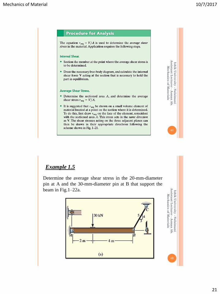
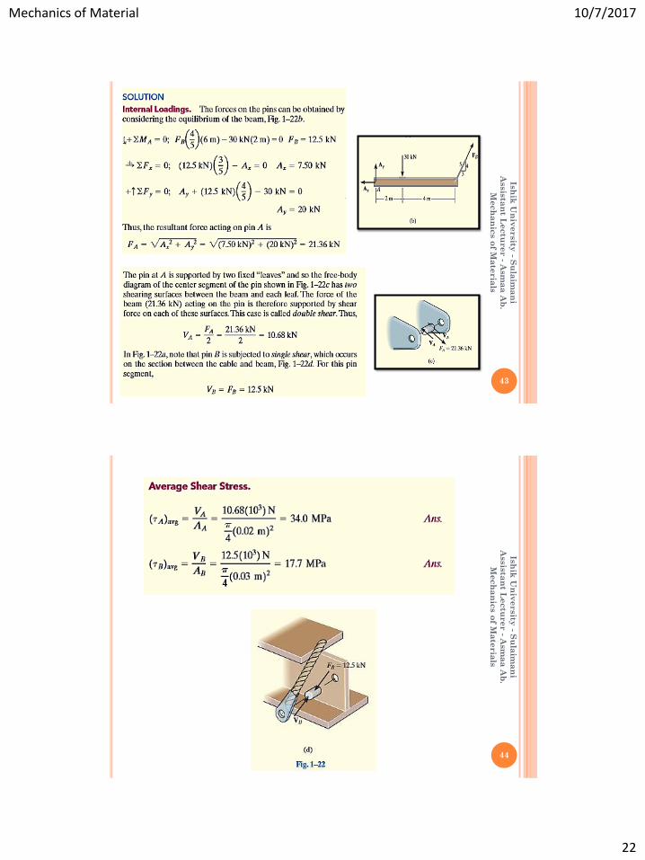
Determine the average shear stress in the 20-mm-diameter
pin at A and the 30-mm-diameter pin at B that support the
beam in Fig.1–22a.
Example 1.5
Mechanics of Material 10/7/2017
22
Ish
ik U
niv
ersity
- Su
laim
an
i
Assis
tan
t Le
ctu
rer - A
sm
aa
Ab
.
Mech
an
ics o
f Ma
teria
ls
43
Ish
ik U
niv
ersity
- Su
laim
an
i
Assis
tan
t Le
ctu
rer - A
sm
aa
Ab
.
Mech
an
ics o
f Ma
teria
ls
44

Mechanics of Material 10/7/2017
23
Ish
ik U
niv
ersity
- Su
laim
an
i
Assis
tan
t Le
ctu
rer - A
sm
aa
Ab
.
Mech
an
ics o
f Ma
teria
ls
45
Example 1.6
The inclined member in Fig.1–24a is subjected to a
compressive force of 600 lb. Determine the average
compressive stress along the smooth areas of contact defined
by AB and BC, and the average shear stress along the
horizontal plane defined by DB.
Ish
ik U
niv
ersity
- Su
laim
an
i
Assis
tan
t Le
ctu
rer - A
sm
aa
Ab
.
Mech
an
ics o
f Ma
teria
ls
46

Mechanics of Material 10/7/2017
24
Ish
ik U
niv
ersity
- Su
laim
an
i
Assis
tan
t Le
ctu
rer - A
sm
aa
Ab
.
Mech
an
ics o
f Ma
teria
ls
47
Assignment 1.3
Determine the average normal stress developed on the cross
section. Sketch the normal stress distribution over the cross
section.
Ish
ik U
niv
ersity
- Su
laim
an
i
Assis
tan
t Le
ctu
rer - A
sm
aa
Ab
.
Mech
an
ics o
f Ma
teria
ls
48
Assignment 1.4
Determine the average normal stress developed in rod AB
if the load has a mass of 50 kg. The diameter of rod AB is 8
mm.

Mechanics of Material 10/7/2017
25
Ish
ik U
niv
ersity
- Su
laim
an
i
Assis
tan
t Le
ctu
rer - A
sm
aa
Ab
.
Mech
an
ics o
f Ma
teria
ls
49
To properly design a structural member or mechanical element
it is necessary to restrict the stress in the material to a level that
will be safe. To ensure this safety, it is therefore necessary to
choose an allowable stress that restricts the applied load to one
that is less than the load the member can fully support. There
are many reasons for doing this. For example, the load for
which the member is designed may be different from actual
loadings placed on it. The intended measurements of a
structure or machine may not be exact, due to errors in
fabrication or in the assembly of its component parts.
Unknown vibrations, impact, or accidental loadings can occur
that may not be accounted for in the design. Atmospheric
corrosion, decay, or weathering tend to cause materials to
deteriorate during service. And lastly, some materials, such as
wood, concrete, or fiber-reinforced composites, can show high
variability in mechanical properties.
7) Allowable Stress
Ish
ik U
niv
ersity
- Su
laim
an
i
Assis
tan
t Le
ctu
rer - A
sm
aa
Ab
.
Mech
an
ics o
f Ma
teria
ls
50
One method of specifying the allowable load for a member
is to use a number called the factor of safety (F.S.). The
factor of safety (F.S.) is a ratio of the failure load Ffail to
the allowable load Fallow. Here Ffail is found from
experimental testing of the material, and the factor of
safety is selected based on experience so that the above
mentioned uncertainties are accounted for when the
member is used under similar conditions of loading and
geometry. Stated mathematically,

Mechanics of Material 10/7/2017
26
Ish
ik U
niv
ersity
- Su
laim
an
i
Assis
tan
t Le
ctu
rer - A
sm
aa
Ab
.
Mech
an
ics o
f Ma
teria
ls
51
If the load applied to the member is linearly related to the
stress developed within the member, as in the case of using
σ = P/A and τavg = V/A , then we can also express the
factor of safety as a ratio of the failure stress σ fail (or τfail)
to the allowable stress σ allow (or τallow);∗that is,
Ish
ik U
niv
ersity
- Su
laim
an
i
Assis
tan
t Le
ctu
rer - A
sm
aa
Ab
.
Mech
an
ics o
f Ma
teria
ls
52
8) Design of Simple Connection
By making simplifying assumptions regarding the behavior of the
material, the equations σ = P/A and τavg = V/A can often be used to
analyze or design a simple connection or mechanical element. In
particular, if a member is subjected to normal force at a section, its
required area at the section is determined from,
On the other hand, if the section is subjected to an average shear force,
then the required area at the section is

Mechanics of Material 10/7/2017
27
Ish
ik U
niv
ersity
- Su
laim
an
i
Assis
tan
t Le
ctu
rer - A
sm
aa
Ab
.
Mech
an
ics o
f Ma
teria
ls
53
Ish
ik U
niv
ersity
- Su
laim
an
i
Assis
tan
t Le
ctu
rer - A
sm
aa
Ab
.
Mech
an
ics o
f Ma
teria
ls
54
Example 1.7
The control arm is subjected to the loading shown in Fig. 1–
26a. Determine to the nearest ¼ in. the required diameter of
the steel pin at C if the allowable shear stress for the steel is
τallow = 8 ksi.

Mechanics of Material 10/7/2017
28
Ish
ik U
niv
ersity
- Su
laim
an
i
Assis
tan
t Le
ctu
rer - A
sm
aa
Ab
.
Mech
an
ics o
f Ma
teria
ls
55
Ish
ik U
niv
ersity
- Su
laim
an
i
Assis
tan
t Le
ctu
rer - A
sm
aa
Ab
.
Mech
an
ics o
f Ma
teria
ls
56

Mechanics of Material 10/7/2017
29
Ish
ik U
niv
ersity
- Su
laim
an
i
Assis
tan
t Le
ctu
rer - A
sm
aa
Ab
.
Mech
an
ics o
f Ma
teria
ls
57
The rigid bar AB shown in Fig. 1–29a is supported by a steel rod AC
having a diameter of 20 mm and an aluminum block having a cross-
sectional area of 1800 mm2 The 18-mm-diameter pins at A and C are
subjected to single shear. If the failure stress for the steel and
aluminum is (σ st) fail = 680 MPa and (σ al) fail = 70 MPa, respectively,
and the failure shear stress for each pin is τfail = 900 MPa determine the
largest load P that can be applied to the bar. Apply a factor of safety of
F.S.=2.
Example 1.8
Ish
ik U
niv
ersity
- Su
laim
an
i
Assis
tan
t Le
ctu
rer - A
sm
aa
Ab
.
Mech
an
ics o
f Ma
teria
ls
58

Mechanics of Material 10/7/2017
30
Ish
ik U
niv
ersity
- Su
laim
an
i
Assis
tan
t Le
ctu
rer - A
sm
aa
Ab
.
Mech
an
ics o
f Ma
teria
ls
59
Ish
ik U
niv
ersity
- Su
laim
an
i
Assis
tan
t Le
ctu
rer - A
sm
aa
Ab
.
Mech
an
ics o
f Ma
teria
ls
60
Assignment 1.5
Determine the maximum average shear stress
developed in each ¾ in-diameter bolt.

Mechanics of Material 10/7/2017
31
Ish
ik U
niv
ersity
- Su
laim
an
i
Assis
tan
t Le
ctu
rer - A
sm
aa
Ab
.
Mech
an
ics o
f Ma
teria
ls
61
Assignment 1.6
If each of the three nails has a diameter of 4 mm and can
withstand an average shear stress of 60 MPa, determine the
maximum allowable force P that can be applied to the
board.
Ish
ik U
niv
ersity
- Su
laim
an
i
Assis
tan
t Le
ctu
rer - A
sm
aa
Ab
.
Mech
an
ics o
f Ma
teria
ls
62
The strut is glued to the horizontal member at surface AB. If
the strut has a thickness of 25 mm and the glue can
withstand an average shear stress of 600 kPa, determine the
maximum force P that can be applied to the strut.
Assignment 1.7

Mechanics of Material 10/7/2017
32
Ish
ik U
niv
ersity
- Su
laim
an
i
Assis
tan
t Le
ctu
rer - A
sm
aa
Ab
.
Mech
an
ics o
f Ma
teria
ls
63
Reference :
1. Mechanics of Materials by R.C.Hibbeler, 8th Edition.