general installation instructions for a ......1. cap for p3101 and p101/n profiles...
TRANSCRIPT

GENERAL INSTALLATION INSTRUCTIONS FOR A SLIDING SYSTEM

GENERAL INSTALLATION INSTRUCTIONS
Measurements
Always measure the balcony at several points vertically (balcony height) and horizontally (balcony length). To determine the height and length of the balcony, use only the smallest vertical and horizontal measurement. Include mounting clearances (depending on your experience), not less than 5 mm.
See the gure above how to measure the dimensions and a few examples of enclosures installed in balconies with irregular shapes.
Balcony enclosure system is always installed in a rectangular space, horizontally and vertically, regardless of the shape of the balcony. When measuring the balcony, pay special attention to irregular shapes and unusual conditions, such as hanging ceiling, bent railing, inclined walls, etc.
-1-
Placing an order
Orders are accepted in writing.
In the order, indicate the width and height of the enclosure as measured withthe instructions on the rst page.Specify the number of panels, the type and thickness of inll, prole colour:– acc. to RAL range (standard: RAL 9016 white)– acc. to Decoral range (wood-like coatings)– anodised,and additional components, such as locks, seals, etc.
Indicate wind conditions at the place of installation (city, installation height above the ground level - which oor) and corrosivity (e.g. proximity to sea).
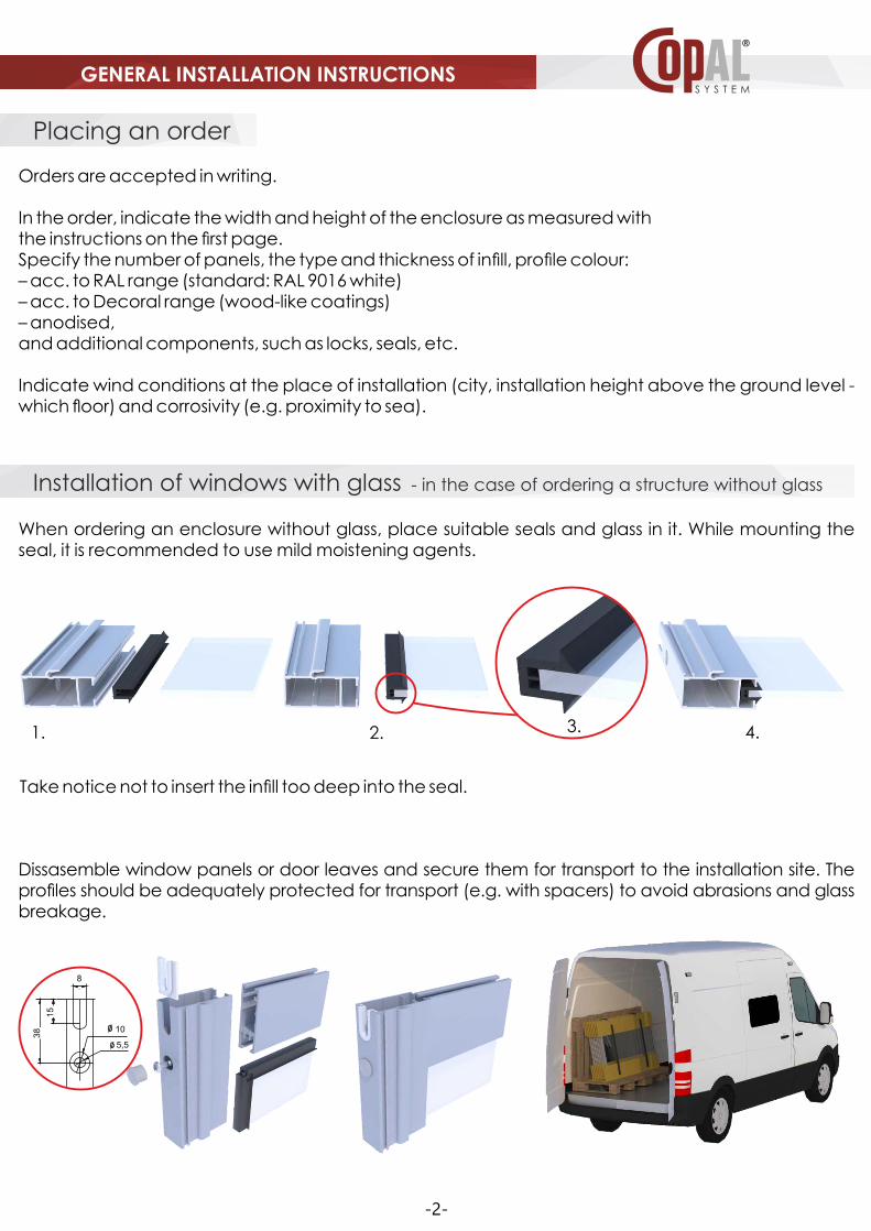
Installation of windows with glass - in the case of ordering a structure without glass
When ordering an enclosure without glass, place suitable seals and glass in it. While mounting the seal, it is recommended to use mild moistening agents.
Take notice not to insert the inll too deep into the seal.
Dissasemble window panels or door leaves and secure them for transport to the installation site. The proles should be adequately protected for transport (e.g. with spacers) to avoid abrasions and glass breakage.
8
39
15
ý10
ý5,50
8
10
5,5
15
38
-2-
1. 2. 4.3.
GENERAL INSTALLATION INSTRUCTIONS

The assembly of bottom guide bar (with drains)
1. Guide bar positioning – set the guide bar with the slope outside to drain the rainwater.
2. Guide bar levelling – level the guide bar along the entire length and use washers, if necessary. Level the guide bar longitudinally and laterally. The guide bar must be supported over its entire length and width.
Outside Inside
1. 2.
3. 4.
AB B
spacer
Outside
Inside
VV
VX
-3-
3. Guide bar installing – screw the guide bar between the rails to provide its stability and resistance against wind load. (A – main mounting point, B – alternative mounting point)
4. If the guide bar has no drainage, cut drain holes in the guide bar every 0.5-1m. Do not cut drain holes in the last internal rail.
Mounting materialsTo install the top and bottom guide bars, it is recommended to use mounting pins, dowels, and washers made of the rust resistant materials. These provide reliant and stable mounting. Use mounting systems in accordance with the manufacturer’s guidelines (type and spacing selected for appropriate surface). Also, keep in mind the correct seal between the guide bars and the surface according to good engineering practices.
GENERAL INSTALLATION INSTRUCTIONS

-4-
Assembly of top guide bar
1. The top guide bar must be mounted directly to the load-bearing surface. Maintain adequate
distances from the edge of the balcony oor to the point of placing the pin/dowel/anchor. Do not
mount the top guide bar through the existing thermal insulation. In the case of thermal insulation,
remove it linearly or at specic points and use appropriate load-bearing spacers, e.g. aluminium
proles2. Placing the guide bar – set the top guide bar parallel to the bottom guide bar. The guide bar rails
should be in a vertical line and the distance between the top and bottom guide bars must be the
same along the entire length.3. Levelling the guide bar – when the location of the top guide bar with reference to the bottom
guide bar is set, level it longitudinally and laterally.4. Installing the guide bar – mount the guide bar to ensure its stability. Remember to seal the guide
bar.
Levelling Sea
lant
Mounting materialsTo install the top and bottom guide bars, it is recommended to use mounting pins, dowels, and washers made of the rust resistant materials. These provide reliant and stable mounting. Use mounting systems in accordance with the manufacturer’s guidelines (type and spacing selected for appropriate surface). Also, keep in mind the correct seal between the guide bars and the surface according to good engineering practices.
NOTE: Maintain the same distance between the guide bars over their entire length (accuracy up to ± 1 mm!). Pay special attention to ensure that the top sash overlaps the top guide bar by at least 5 mm (safe dimension of use).
GENERAL INSTALLATION INSTRUCTIONS

Panel inserting
Mounting P304 side profile1. Place the c-rail (P304) on the vertical prole of the panel.2. Slide the window with P304 to the mounting place of the side prole.3. Adjust the clearance between the window prole and P304 frame prole.4. Draw the place of mounting.5. Mount P304. If necessary, adjust, add washers, and seal the connection area between P304 and the wall.
Mounting materialsTo install P304 c-rail, it is recommended to use mounting pins and washers made of rust resistant materials. In external enclosures, remember to seal the installed parts with the installation surface according to good engineering practices.
IMPORTANT: When completing the installation, remove plaster and mortar residues, metal lings, dust dirt, etc. Prevent leaving metal elements that are not-secured against corrosion.
Insert the windows, starting with the outermost panel. Note that rollers are mounted in the bottom horizontal prole.
1. Insert the top of the panel into the top guide bar until stop.2. Set the panel vertically.3. Drop the panel onto the bottom guide bar.4. Check the clearance between the panel and the top guide bar along its entire length and adjust make the clearance, if necessary.
1. 3.
2.
4.
1.2.
3.
4.
Outside
Inside
min. 5 mmmax 8 mm
Important:Remember to check the adjustment.
If the tting is too tight, it will prevent the panels from being removed.
If the tting is too loose, the panel may fall out (use safe dimension of use – the panel overlaps the top guide bar by at least 5 mm)
1.
2. 3. 4. 5.
recommended clearance
about 1.5mm
-5-
GENERAL INSTALLATION INSTRUCTIONS

Guide bar installation methodsBottom guide bar installation methods depend on the type of balcony railing. The solutions presented below are only examples of those most commonly used.
Infill with different thicknessesCOPAL system is designed for inlls with thicknesses between 4 and 18 mm. The gures show the preparation of the glass slit for inlls with different thicknesses. Remember that if the sash weight is over 50 kg, use double bearings.
4 to 5 mm 6 mmpanel or
polycarbonate 8 mm16 mm
P121 or P126 guide bar P3121 guide bar
panel or polycarbonate 18 mm
Types of glasses in COPAL balcony and terrace enclosures:A) SINGLE glass: standard oat glass, 4, 5, 6 mm thickness; ESG tempered glass, 4.5 and 6 mm thickness;
VSG laminated safety glass, thickness 6.4 mm (3.3.1)B) DOUBLE glass: we recommend double pane set, thickness 16 mm, composed of two tempered glass
panes, thickness 4 mm, on an 8 mm frame (ESG4-Ar8-ESG4).In order to limit heat emission to the inside of the enclosure, panes with low-emission coating can be ordered.
-6-
Tools and equipment
N-1 – presser for mounting P119 Tool for pressing P119 prole for quick and stable mounting to the main structure prole. After 1/4 turn, the two proles are xed together.
N2 pneumatic cutter (or N-9 scissors)Cutter for making holes in guide bars. Tool for cutting drain holes at the surface of the bottom guide bar. Cut the holes alternatively in individual guide bar rails.
GENERAL INSTALLATION INSTRUCTIONS
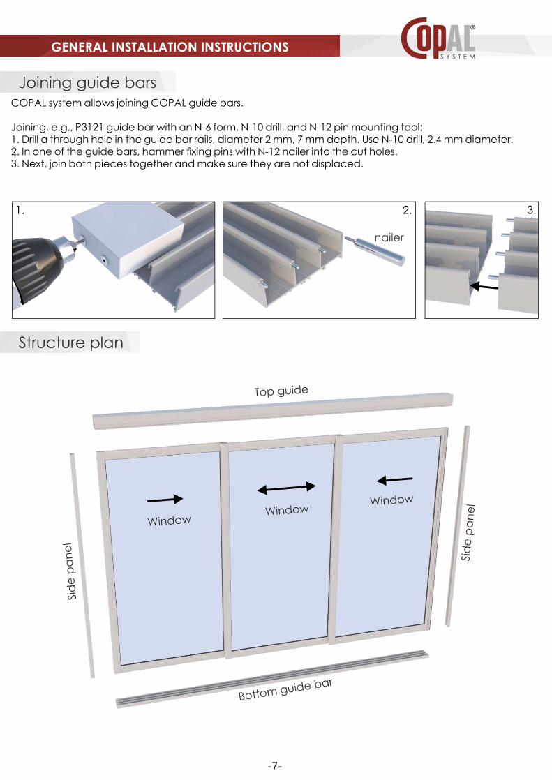
Joining guide barsCOPAL system allows joining COPAL guide bars.
Joining, e.g., P3121 guide bar with an N-6 form, N-10 drill, and N-12 pin mounting tool:1. Drill a through hole in the guide bar rails, diameter 2 mm, 7 mm depth. Use N-10 drill, 2.4 mm diameter.2. In one of the guide bars, hammer xing pins with N-12 nailer into the cut holes.3. Next, join both pieces together and make sure they are not displaced.
1. 2. 3.
Structure plan
Top guide
nailer
Bottom guide bar
Sid
e p
an
el
Sid
e p
an
el
WindowWindow
Window
-7-
GENERAL INSTALLATION INSTRUCTIONS

-8-
Railways
P 3121 P 121 P3124+P3125 P 122 P 121/2T P103+P104
P 108 P 126-4T P 126-3T P 126-2T P 126-1T P126
79
46
79
49
7979
24 24
54
10481
39,5
27
24
242424
24
24
24
56
81
48
9
25
(only the top part)
(bottom towards a cupboard)
(only the top part)
Upper window profile - P3102
50
16
E 101 seal – 2 profile lengthsE 201 PTFE slider (only with P106 profile)
E 309 stainless screw – 2 per profile
Lower window profile - P3102
P. 107 – prole for cabinets, only with P 108 guiding bar and E 205 adjustable bearing
P 3102
50
50
16
16
E 205 – 2 pcs. per profile
E 203 – 2 or 4 pcs. per profile
For sashes weighing more than 50kg, join bearings in pairs.
E 304 – 2 pcs. per profile
E 309 – 2 pcs. per profile
E 101 – 2 profile lengths
E 101 – 2 profile lengths
Side profile – P304
30
23
Side profile, closingP304 – 2 pcs for single enclosure
60 40 19
GENERAL INSTALLATION INSTRUCTIONS
-9-
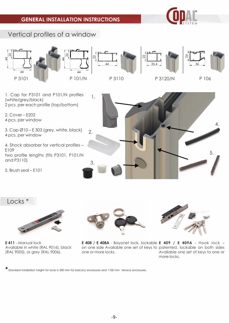
E 408 / E 408A - Bayonet lock, lockable on one side Available one set of keys to one or more locks.
Locks *
E 409 / E 409A - Hook lock – patented, lockable on both sides Available one set of keys to one or more locks.
E 411 - Manual lockAvailable in white (RAL 9016), black (RAL 9005), or grey (RAL 9006).
* Standard installation height for locks is 300 mm for balcony enclosures and 1100 mm terrace enclosures.
1. Cap for P3101 and P101/N profiles (white/grey/black) 2 pcs. per each profile (top/bottom)
2. Cover – E2024 pcs. per window
3. Cap Ø10 – E 303 (grey, white, black)4 pcs. per window
4. Shock absorber for vertical profiles – E109two profile lengths (fits P3101, P101/N and P3110)
5. Brush seal – E101
Vertical profiles of a window
P 3120/NP 3110 P 106P 3101 P 101/N
35,444 36
22 24
22
44
44
22
44
44
22
5.
2.
1.
4.
3.
GENERAL INSTALLATION INSTRUCTIONS

Economic and functional
The profile is used with E408 and E411 locks.
The profile is used with E408, E409, and E411 locks.
The profile is used withE408, E409, andE411 locks.
The profile is used withE408, E409, andE411 locks
The profile is used withE408, E409, andE411 locks.
P 3120/N
Economic and functional with increased strength parametersP 3110 / P110
Maximum functionality thanks to pulls in profile and increased rigidityP 3101 / P101N
Functional pull on the inside of the enclosureP 3101 , P 101N / P3110 , P110
Pull on the far profiles of the enclosure.P 3101 , P 101N / P3110 , P110
Examples
The system is for low balcony enclosures mounted on railing, sliding windows, teller windows, and furniture with sliding components. E4203 and E4204 pulls can be used for opening.
The system is used for terrace enclosures, sliding doors. The pull in the prole makes it easy to slide the components from both outside and inside of the enclosure. Additionally, this prole very well affects the rigidity of the whole structure.
The size of a single window depends on the type of inll used and wind load, among others. If you have any further questions, please contact us by phone or email to receive a performance report of a given structure.
The system is for balcony and terrace enclosures, sliding doors, sliding walls, windows, and furniture with sliding components. E4203 and E4204 pulls can be used for opening.
The system is for balcony and terrace enclosures, sliding doors, sliding walls, windows. The pull on the inner proles makes it easy to slide the components from the inside of the enclosure and increases the rigidity of the structure.
The system is for balcony and terrace enclosures, sliding doors, sliding walls, windows. The pull on the inner proles makes it easy to slide the components from the inside of the enclosure and increases the rigidity of the structure.
-10-
GENERAL INSTALLATION INSTRUCTIONS

Examples
screwseal
E 104
vertical bar
vertical bar
P 109
P3109
P3108E110E117
E115E116
Horizontal cross-section of sliding enclosure
Vertical cross-section of sliding enclosure
Horizontal cross-section of sliding enclosure with fixed components
Teller window cross-section, sliding up/down
P 304
(side prole)
Vertical proles
E 101brush seal
bumper(shock absorber)E 109
P. 101/N orP 3101 orP 3110 orP 3120/N
Example of a sliding wall with xed wall components in two versions:
Glazing prole, P109andFixed structure proles: P3109 and P3108
The window can be equipped with a counterweight to position the sliding sash at any height.
B B
A
A
B-B
A-A
P3121 orP121 orP105 orP3124+P3125(telescopic)
P3121 orP121 orP122 orP105
P. 3102(top and bottom horizontal prole)
E 203
(bearing)
outside inside
-11-
GENERAL INSTALLATION INSTRUCTIONS