general safety instructions · nota : accessories with pre-fitted studs can be used (studs -...
TRANSCRIPT
10
General safety instructions
Only qualified persons over 18 years of age can be permitted to use a stud driver. These persons must know perfectly how the tool works and must follow exactly the manufacturer’s instructions and the safety regulations. They must be capable of maintaining the tool.
The charges and studs used must be exclusively those designed and manufactured by SPIT for this tool.
The SPITFIRE P370 must be checked before use, so as to ensure that the safety devices are working properly and that the front end and the munition carrier are clean. Also ensure that the moving part generally slides well.
The tool must be loaded just before use. If the tool is not in use, it must be unloaded and put back into its original packing. It must not under any circumstances be transported loaded.
When firing, the operator must be in a stable position. The tool must be held at right angles to the base material.
When a firing incident occurs, the tool must be unloaded immediately, taking all necessary precautions. If several incidents occur, inform the manufacturer.
The SPITFIRE P370 and its chargers must only be transported in their original packing.
Never point the end of the stud driver at anyone. The driver must always be pointed downwards.
Never operate the driver with the flat of the hand. The manufacturer must check the condition of the tool, even if it is not used, at
least once a year. It is prohibited for unauthorized persons to use a stud driver. It is prohibited to make any modification to the tool other than those specified in this
manual. It is prohibited to do stud driving on profiled sheet on a metal structure before having
ensured that there is no-one behind it. Fixing must not be attempted at a point where the profiled sheet support iron has
been damaged or is defective. Fixing must be done at least 2 cm away from this area.
It is prohibited to attempt fixing on materials which are not rigid or strong enough: hollow brick, plasterboard, slate, etc.
It is prohibited to drive studs into brittle, hard materials, like cast iron, hardened steel, marble or granite.
It is prohibited to do any fixing on concrete less than 10 cm from the edges. It is prohibited to use a stud driver in workshops or other premises where there are
explosion risks. When using the tool, the user and bystanders must wear suitable safety glasses, a
hard hat and hearing protection.
Notice 010_GB.indd 26/02/04, 7:5110

11
GB
General
The SPITFIRE P370 is a high-tech stud driver. • Automatic rising of the inertia block• Automatic feeding of studs• Automatic feeding of charges
It is designed for fixing on concrete and steel.
It is an indirect firing tool, of class A symbol A*, complying with French standards NFE 71-100 and 71-101.
The SPITFIRE P370 requires two conditions to obtain percussion:• To be held firmly resting against the support.• To press the trigger.
Detailed instructions for use are presented in the following pages of this manual. It is essential to familiarize yourself with them before using your SPITFIRE P370.
This tool is approved by the St-Etienne Testing Stand under n° 001137
Notice 010_GB.indd 26/02/04, 7:5111
12
Technical characteristics
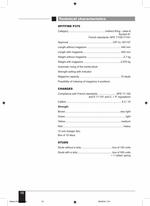
SPITFIRE P370
Category....................................................Indirect firing - class A Symbol A*
French standards: NFE 71100-71101
Approval ..............................................................CIP no. 001137
Length without magazine ............................................... 440 mm
Length with magazine .................................................... 455 mm
Weight without magazine ...................................................2.7 kg
Weight with magazine ....................................................2.875 kg
Automatic rising of the inertia block
Strength setting with indicator
Magazine capacity..........................................................10 studs
Possibility of indexing of magazine 4 positions
CHARGES
Compliance with French standards .......................... NFE 71-100 and E 71-101 and C. I. P. regulations
Calibre .............................................................................6.3 / 10
Strength
Brown ............................................................................ very light
Green .................................................................................... light
Yellow ..............................................................................medium
Red.....................................................................................heavy
10 unit charger discBox of 10 discs
STUDS
Studs without a strip ........................................... box of 100 units
Studs with a strip ................................................ box of 500 units + 1 rubber spring
Notice 010_GB.indd 26/02/04, 7:5112
13
GB
Using the tool
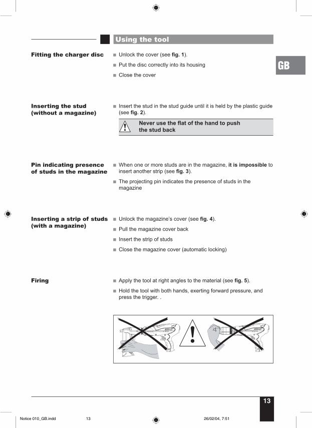
Fitting the charger disc Unlock the cover (see fig. 1).
Put the disc correctly into its housing
Close the cover
Inserting the stud(without a magazine)
Insert the stud in the stud guide until it is held by the plastic guide (see fig. 2).
Never use the flat of the hand to push the stud back
Firing Apply the tool at right angles to the material (see fig. 5).
Hold the tool with both hands, exerting forward pressure, and press the trigger. .
Pin indicating presence of studs in the magazine
When one or more studs are in the magazine, it is impossible to insert another strip (see fig. 3).
The projecting pin indicates the presence of studs in the magazine
Inserting a strip of studs(with a magazine)
Unlock the magazine’s cover (see fig. 4).
Pull the magazine cover back
Insert the strip of studs
Close the magazine cover (automatic locking)
Notice 010_GB.indd 26/02/04, 7:5113
14
Using the tool
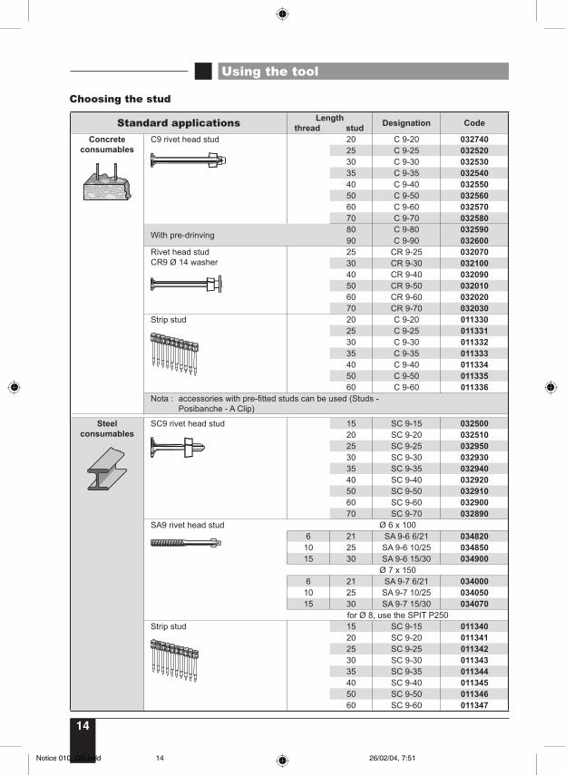
Choosing the stud
Standard applications Length thread stud Designation Code
Concrete consumables
C9 rivet head stud 20 C 9-20 03274025 C 9-25 03252030 C 9-30 03253035 C 9-35 03254040 C 9-40 03255050 C 9-50 03256060 C 9-60 03257070 C 9-70 032580
With pre-drinving80 C 9-80 03259090 C 9-90 032600
Rivet head studCR9 Ø 14 washer
25 CR 9-25 03207030 CR 9-30 03210040 CR 9-40 03209050 CR 9-50 03201060 CR 9-60 03202070 CR 9-70 032030
Strip stud 20 C 9-20 01133025 C 9-25 01133130 C 9-30 01133235 C 9-35 01133340 C 9-40 01133450 C 9-50 01133560 C 9-60 011336
Nota : accessories with pre-fitted studs can be used (Studs - Posibanche - A Clip)
Steel consumables
SC9 rivet head stud 15 SC 9-15 03250020 SC 9-20 03251025 SC 9-25 03295030 SC 9-30 03293035 SC 9-35 03294040 SC 9-40 03292050 SC 9-50 03291060 SC 9-60 03290070 SC 9-70 032890
SA9 rivet head stud Ø 6 x 1006 21 SA 9-6 6/21 034820
10 25 SA 9-6 10/25 03485015 30 SA 9-6 15/30 034900
Ø 7 x 1506 21 SA 9-7 6/21 034000
10 25 SA 9-7 10/25 03405015 30 SA 9-7 15/30 034070
for Ø 8, use the SPIT P250Strip stud 15 SC 9-15 011340
20 SC 9-20 01134125 SC 9-25 01134230 SC 9-30 01134335 SC 9-35 01134440 SC 9-40 01134550 SC 9-50 01134660 SC 9-60 011347
Notice 010_GB.indd 26/02/04, 7:5114
15
GB
Checking the wear parts
The tool is equipped with a rubber spring (3) (for the return of the inertia block), an inertia block + insulation ring assembly (2) (see fig. 8).
These parts must be checked at regular intervals
Wear part CheckSpring (3) - length (min. 161 mm)
- Condition (cuts, wear, etc.)
Insulation ring + inertia block (2)
- Thickness (mini 4 mm)- Condition (cuts, wear, etc.)- No chipped part on the inertia block
Using the tool
Choosing the charge(see fig. 6)
- 031740 brown 6.3/10 disc charge - very light- 031600 green 6.3/10 disc charge - light- 031700 yellow 6.3/10 disc charge - medium- 011658 red 6.3/10 disc charge - heavy
Tips :
Choose according to :• the nature and hardness of the support material• the length of the stud• the nature of the part to be fixed
Proceed by successive trials, beginning with the lightest strength, then increase if necessary.
If the charge has misfired, wait for 20 seconds, keeping the tool on the work surface, then stop pressing in order to reset the percussion system and to resume firing.
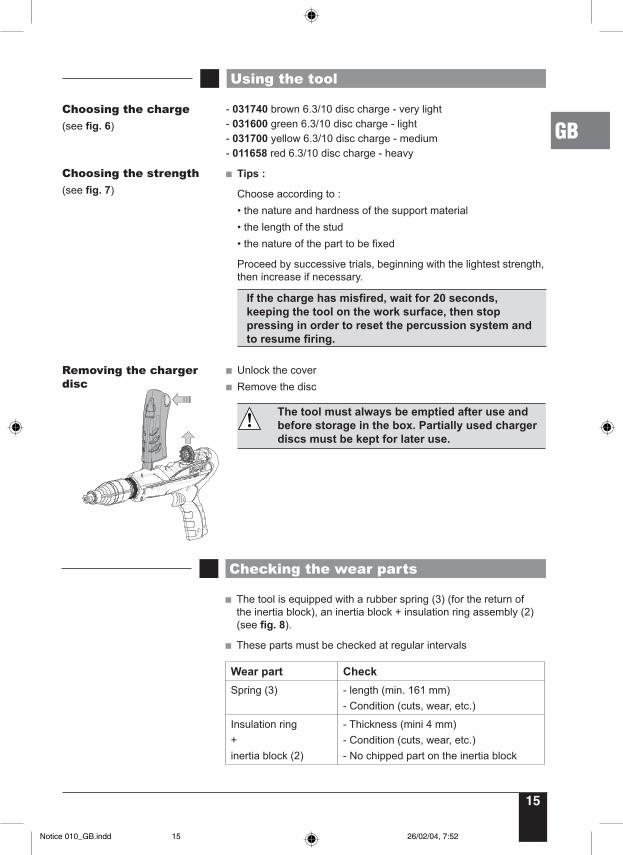
Unlock the cover Remove the disc
The tool must always be emptied after use and before storage in the box. Partially used charger discs must be kept for later use.
Removing the charger disc
Choosing the strength(see fig. 7)
Notice 010_GB.indd 26/02/04, 7:5215
16
Front part
Always unload the tool:
- on completion of work,- before changing any parts (inertia block, dampers, etc.)- before doing any cleaning or maintenance
Disassembly Hold the tool vertical, resting on the back (see fig. 9)• Unscrew the tool’s nose (stud guide or magazine).If the effort seems too great, use a 16 mm spanner.
Take out the inertia block with the ring and the spring (see fig. 10)
Unscrew and take out the barrel assembly (push the barrel downwards and turn (see fig. 11)
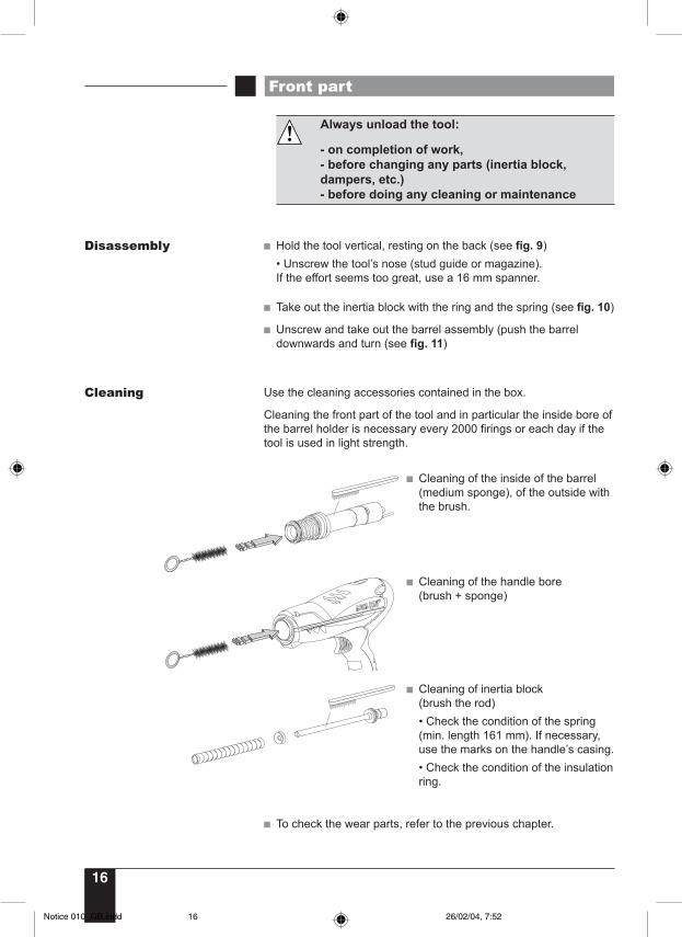
Cleaning Use the cleaning accessories contained in the box.
Cleaning the front part of the tool and in particular the inside bore of the barrel holder is necessary every 2000 firings or each day if the tool is used in light strength.
Cleaning of the inside of the barrel (medium sponge), of the outside with the brush.
Cleaning of the handle bore(brush + sponge)
Cleaning of inertia block(brush the rod)• Check the condition of the spring (min. length 161 mm). If necessary, use the marks on the handle’s casing. • Check the condition of the insulation ring.
To check the wear parts, refer to the previous chapter.
Notice 010_GB.indd 26/02/04, 7:5216
17
GB
Front part
TIPS
Powder-actuated tools require regular maintenance to remove the carbon deposited by combustion fumes. Whenever the tool requires unusual force, or when there is a lack of strength or percussion of the charge without driving in the stud, dismantle the front part and clean the bore of the barrel, the charge and the inertia block.
It is essential to use SPIT lubricant for maintenance. We recommend wiping parts after oiling them.
Cleaning (continued)
Reassembly Reassembly is the reverse of disassembly
Position the barrel’s groove at the top (see fig. 12)
Insert the barrel assembly in the handle and screw the knurled ring
After reassembly, check that the barrel slides properly in the handle
Insert the insulation ring on the inertia block’s rod
Insert the rubber ring on the rod
Position the inertia block assembly in the barrel
Screw up the magazine (until the first “click” and turn once) or the stud guide.
Damage to the end of the inertia block can be the cause of poor fixing:- fixing not at right angles- shearing of the stud on penetration• Check the wear or possible deformation of the inertia block. Deformation of the end can be trued up by grinding up to 3 mm by making a chamfer. Keep the ground surface at right angles to the centre line of the inertia block.
Notice 010_GB.indd 26/02/04, 7:5217
18
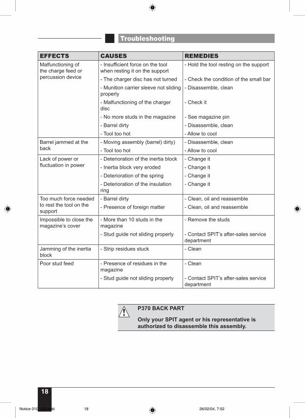
EFFECTS CAUSES REMEDIESMalfunctioning of the charge feed or percussion device
- Insufficient force on the tool when resting it on the support
- Hold the tool resting on the support
- The charger disc has not turned - Check the condition of the small bar- Munition carrier sleeve not sliding properly
- Disassemble, clean
- Malfunctioning of the charger disc
- Check it
- No more studs in the magazine - See magazine pin- Barrel dirty - Disassemble, clean- Tool too hot - Allow to cool
Barrel jammed at the back
- Moving assembly (barrel) dirty) - Disassemble, clean- Tool too hot - Allow to cool
Lack of power or fluctuation in power
- Deterioration of the inertia block - Change it- Inertia block very eroded - Change it- Deterioration of the spring - Change it- Deterioration of the insulation ring
- Change it
Too much force needed to rest the tool on the support
- Barrel dirty - Clean, oil and reassemble- Presence of foreign matter - Clean, oil and reassemble
Impossible to close the magazine’s cover
- More than 10 studs in the magazine
- Remove the studs
- Stud guide not sliding properly - Contact SPIT’s after-sales service department
Jamming of the inertia block
- Strip residues stuck - Clean
Poor stud feed - Presence of residues in the magazine
- Clean
- Stud guide not sliding properly - Contact SPIT’s after-sales service department
Troubleshooting
P370 BACK PART
Only your SPIT agent or his representative is authorized to disassemble this assembly.
Notice 010_GB.indd 26/02/04, 7:5218