general sio driver - hmisource.com€¦ · general sio driver gp-pro ex device/plc connection...
TRANSCRIPT

1
Digital Electronics Corporation
General SIO Driver
1 What Is a General SIO?................................................................................................... 3
2 System Configuration....................................................................................................... 5
3 External Device Selection ................................................................................................ 8
4 Communication Settings .................................................................................................. 9
5 Setup Items .................................................................................................................... 12
6 Cable Diagrams ............................................................................................................. 15
7 Supported Devices......................................................................................................... 31
8 Device Code and Address Code.................................................................................... 32
9 Error Messages.............................................................................................................. 33
10 Direct Communication Function ..................................................................................... 35
11 Sample Program ............................................................................................................ 47
General SIO Driver
GP-Pro EX Device/PLC Connection Manual 2
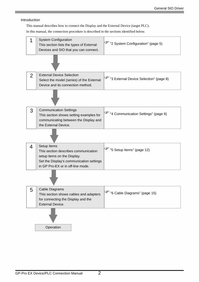
IntroductionThis manual describes how to connect the Display and the External Device (target PLC).
In this manual, the connection procedure is described in the sections identified below.
1 System ConfigurationThis section lists the types of External Devices and SIO that you can connect.
"2 System Configuration" (page 5)
2 External Device SelectionSelect the model (series) of the External Device and its connection method.
"3 External Device Selection" (page 8)
3 Communication SettingsThis section shows setting examples for communicating between the Display and the External Device.
"4 Communication Settings" (page 9)
4 Setup ItemsThis section describes communication setup items on the Display.Set the Display's communication settings in GP Pro-EX or in off-line mode.
"5 Setup Items" (page 12)
Operation
5 Cable DiagramsThis section shows cables and adapters for connecting the Display and the External Device.
"6 Cable Diagrams" (page 15)

General SIO Driver
GP-Pro EX Device/PLC Connection Manual 3
1 What Is a General SIO?
1.1 Overview
The general SIO driver is a driver which can be used for general purpose and not dedicated to specific SIO
communication devices connected to the Display. It is suitable for devices with simple communication
procedures, such as temperature controllers, card readers, barcode or serial printers.
Through the Display's D-script and ladder program (hereinafter referred to as “scripts”), communication packets
are created as data in the Display's memory table. The general SIO driver then sends the memory table data to the
Display's SIO port, and stores data received from the SIO port in the Display's memory table.
As described above, the communication packets themselves are created using scripts and this driver enables you
to send and receive data to and from SIO communication devices using only Send/Receive functions through the
SIO ports.
• 1:1 and 1:n serial connections are available.
• Up to 31 units can be connected.
• The maximum communication speed is 115200bps.
• The general SIO driver features a memory link method. You can set a single memory link driver for each Display. Two or more memory link drivers are not available for simultaneous use.For more information on the memory link method, see the GP-Pro EX Device/PLC Connection Manual. In the Manufacturer’s List section, see "Communication Method" under "Important: Prior to reading the Device/PLC Connection manual".
General SIO Driver
GP-Pro EX Device/PLC Connection Manual 4
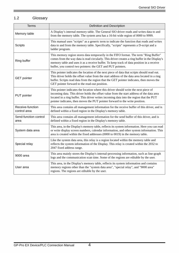
1.2 Glossary
Terms Definition and Description
Memory table A Display’s internal memory table. The General SIO driver reads and writes data to and from the memory table. The system area has a 16-bit wide region of 0000 to 9999.
ScriptsThis manual uses "scripts" as a generic term to indicate the function that reads and writes data to and from the memory table. Specifically, "scripts" represents a D-script and a ladder program.
Ring buffer
This memory region stores data temporarily in the FIFO format. The term "Ring Buffer" comes from the way data is read circularly. This driver creates a ring buffer in the Display's memory table and uses it as a receive buffer. To keep track of data position in a receive buffer, you control two pointers: the GET and PUT pointers.
GET pointer
This pointer indicates the location of the next piece of data that scripts should read out. This driver holds the offset value from the start address of the data area located in a ring buffer. Scripts read data from the region that the GET pointer indicates, then moves the GET pointer forward to the read-out position.
PUT pointer
This pointer indicates the location where this driver should write the next piece of incoming data. This driver holds the offset value from the start address of the data area located in a ring buffer. This driver writes incoming data into the region that the PUT pointer indicates, then moves the PUT pointer forward to the write position.
Receive-function control area
This area contains all management information for the receive buffer of this driver, and is defined within a fixed region in the Display's memory table.
Send-function control area
This area contains all management information for the send buffer of this driver, and is defined within a fixed region in the Display's memory table.
System data areaThis area, in the Display's memory table, reflects its system information. Here you can read or write display screen numbers, calendar information, and other system information. This area is created within the fixed addresses (0000 to 0019) in the memory table.
Special relayLike the system data area, this relay is a region located within the memory table and reflects the system information of the Display. This relay is created within the 2032 to 2047 fixed address range.
9000 area This area mainly stores the Display's internal-processing information, such as line-graph logs and the communication scan time. Some of the regions are editable by the user.
User areaThis area, in the Display's memory table, reflects its system information and contains memory regions other than the "system data area", "special relay", and "9000 area" regions. The regions are editable by the user.
General SIO Driver
GP-Pro EX Device/PLC Connection Manual 5
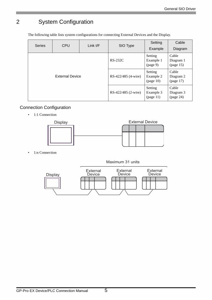
2 System Configuration
The following table lists system configurations for connecting External Devices and the Display.
Connection Configuration• 1:1 Connection
• 1:n Connection
Series CPU Link I/F SIO TypeSetting
Example
Cable
Diagram
External Device
RS-232CSetting Example 1 (page 9)
Cable Diagram 1 (page 15)
RS-422/485 (4-wire)Setting Example 2 (page 10)
Cable Diagram 2 (page 17)
RS-422/485 (2-wire)Setting Example 3 (page 11)
Cable Diagram 3 (page 24)
Display External Device
ExternalDevice
ExternalDeviceDisplay
ExternalDevice
Maximum 31 units

General SIO Driver
GP-Pro EX Device/PLC Connection Manual 6
IPC COM PortWhen connecting an IPC with an External Device, the COM port used depends on the series and SIO type. Please
refer to the IPC manual for details.
Usable Port
DIP switch setting: RS-232C
SeriesUsable Port
RS-232C RS-422/485(4 wire) RS-422/485(2 wire)
PS-2000B COM1*1 , COM2, COM3*1, COM4
*1 The RI/5V can be switched. Use the IPC’s switch to change if necessary.
- -
PS-3450A, PS-3451A COM1, COM2*1*2 COM2*1*2 COM2*1*2
PS-3650A, PS-3651A COM1*1 - -
PS-3700A (Pentium®4-M)PS-3710A
COM1*1, COM2*1, COM3*2 , COM4
*2 Set up the SIO type with the DIP switch. Please set up as follows according to SIO type to be used.
COM3*2 COM3*2
PS-3711A COM1*1, COM2*2 COM2*2 COM2*2
PL-3000B, PL-3600T,PL-3600K, PL-3700T,PL-3700K, PL-3900T
COM1*1*2, COM2*1, COM3, COM4 COM1*1*2 COM1*1*2
DIP switch Setting Description
1 OFF*1
*1 When using PS-3450A and PS-3451A, turn ON the set value.
Reserved (always OFF)
2 OFFSIO type: RS-232C
3 OFF
4 OFF Output mode of SD (TXD) data: Always output
5 OFF Terminal resistance (220Ω) insertion to SD (TXD): None
6 OFF Terminal resistance (220Ω) insertion to RD (RXD): None
7 OFF Short-circuit of SDA (TXA) and RDA (RXA): Not available
8 OFF Short-circuit of SDB (TXB) and RDB (RXB): Not available
9 OFFRS (RTS) Auto control mode: Disabled
10 OFF
General SIO Driver
GP-Pro EX Device/PLC Connection Manual 7
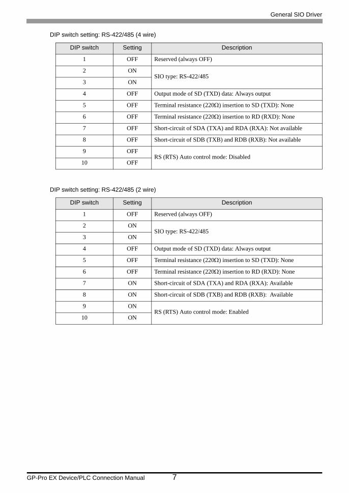
DIP switch setting: RS-422/485 (4 wire)
DIP switch setting: RS-422/485 (2 wire)
DIP switch Setting Description
1 OFF Reserved (always OFF)
2 ONSIO type: RS-422/485
3 ON
4 OFF Output mode of SD (TXD) data: Always output
5 OFF Terminal resistance (220Ω) insertion to SD (TXD): None
6 OFF Terminal resistance (220Ω) insertion to RD (RXD): None
7 OFF Short-circuit of SDA (TXA) and RDA (RXA): Not available
8 OFF Short-circuit of SDB (TXB) and RDB (RXB): Not available
9 OFFRS (RTS) Auto control mode: Disabled
10 OFF
DIP switch Setting Description
1 OFF Reserved (always OFF)
2 ONSIO type: RS-422/485
3 ON
4 OFF Output mode of SD (TXD) data: Always output
5 OFF Terminal resistance (220Ω) insertion to SD (TXD): None
6 OFF Terminal resistance (220Ω) insertion to RD (RXD): None
7 ON Short-circuit of SDA (TXA) and RDA (RXA): Available
8 ON Short-circuit of SDB (TXB) and RDB (RXB): Available
9 ONRS (RTS) Auto control mode: Enabled
10 ON

General SIO Driver
GP-Pro EX Device/PLC Connection Manual 8
3 External Device Selection
Select the External Device to be connected to the Display.
Setup Items Setup Description
Maker Select the maker of the External Device to be connected. Select "Digital Electronics Corporation".
Series
Select the model (series) of the External Device to be connected and connection method. Select "General SIO".Check the connection configuration in "General SIO" in system configuration.
"2 System Configuration" (page 5)
Use System Area Not available in this driver.
Port Select the Display port to be connected to the External Device.

General SIO Driver
GP-Pro EX Device/PLC Connection Manual 9
4 Communication Settings
This section provides examples of communication settings recommended by Pro-face for the Display and the
External Device.
4.1 Setting Example 1
GP-Pro EX Settings
Communication Settings
To display the setup screen, from the [System Settings] workspace, select [Device/PLC].
External Device SettingsThe communication settings vary depending on the External Device.
Refer to your External Device manual for details.

General SIO Driver
GP-Pro EX Device/PLC Connection Manual 10
4.2 Setting Example 2
GP-Pro EX Settings
Communication Settings
To display the setup screen, from the [System Settings] workspace, select [Device/PLC].
External Device SettingsThe communication settings vary depending on the External Device.
Refer to your External Device manual for details.

General SIO Driver
GP-Pro EX Device/PLC Connection Manual 11
4.3 Setting Example 3
GP-Pro EX Settings
Communication Settings
To display the setup screen, from the [System Settings] workspace, select [Device/PLC].
External Device SettingsThe communication settings vary depending on the External Device.
Refer to your External Device manual for details.

General SIO Driver
GP-Pro EX Device/PLC Connection Manual 12
5 Setup Items
Set up the Display's communication settings in GP Pro-EX or in the Display's off-line mode.
The setting of each parameter must match that of the External Device.
"4 Communication Settings" (page 9)
5.1 Setup Items in GP-Pro EX
Communication SettingsTo display the setup screen, from the [System Settings] workspace, select [Device/PLC].
Setup Items Setup Description
SIO Type Select the SIO type to communicate with the External Device.
Speed Select the communication speed between the External Device and the Display.
Data Length Select the data length.
Parity Select how to check parity.
Stop Bit Select the stop bit length.
Flow Control Select a communication control method to prevent transmission and reception data overflow.
Wait To Send Use an integer from 0 to 255 to enter standby time (ms) for the Display from receiving packets to transmitting next commands.
Control Area Address
Use an integer from 20 to 9980 to enter the control area address.
• Do not duplicate start addresses.
RI/VCCYou can switch RI/VCC of the 9th pin when you select RS232C for SIO type.When connecting with the IPC, it is necessary to change RI/5V using the IPC changeover switch. Refer to the IPC manual for details.

General SIO Driver
GP-Pro EX Device/PLC Connection Manual 13
5.2 Setup Items in Off-line Mode
Communication SettingsTo display the setting screen, touch [Device/PLC Settings] from [Peripheral Equipment Settings] in off-line mode.
Touch the External Device you want to set from the displayed list.
• Refer to the Maintenance/Troubleshooting manual for information on how to enter off-line mode or about the operation.
Cf. Maintenance/Troubleshooting Manual "2.2 Off-line Mode"
Setup Items Setup Description
SIO Type Select the SIO type to communicate with the External Device.
Speed Select the communication speed between the External Device and the Display.
Data Length Select the data length.
Parity Select how to check parity.
Stop Bit Select the stop bit length.
Flow Control Select a communication control method to prevent transmission and reception data overflow.
Wait To Send Use an integer from 0 to 255 to enter standby time (ms) for the Display from receiving packets to transmitting next commands.
Control Area Address
Use an integer from 20 to 9980 to enter the control area address.
• Do not duplicate start addresses.
General SIO Driver
GP-Pro EX Device/PLC Connection Manual 14
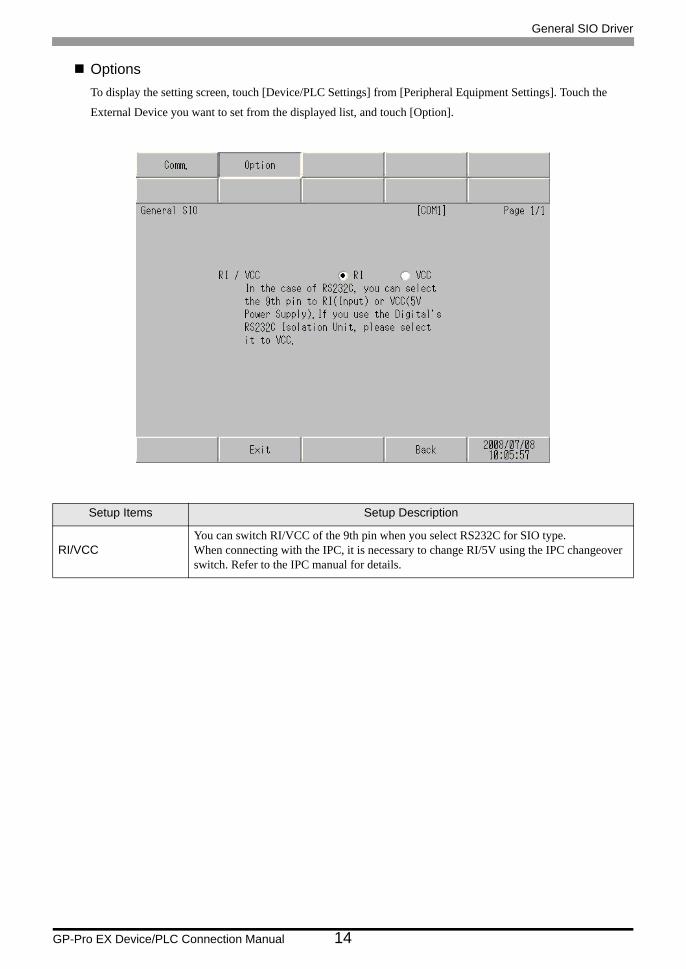
OptionsTo display the setting screen, touch [Device/PLC Settings] from [Peripheral Equipment Settings]. Touch the
External Device you want to set from the displayed list, and touch [Option].
Setup Items Setup Description
RI/VCCYou can switch RI/VCC of the 9th pin when you select RS232C for SIO type.When connecting with the IPC, it is necessary to change RI/5V using the IPC changeover switch. Refer to the IPC manual for details.

General SIO Driver
GP-Pro EX Device/PLC Connection Manual 15
6 Cable Diagrams
The following cable diagrams may be different from cable diagrams recommended by Pro-face. Please be assured
there is no operational problem in applying the cable diagrams shown in this manual.
• The FG pin of the External Device body must be D-class grounded. Refer to your External Device manual for
details.
• The SG and FG are connected inside the Display. When connecting the External Device to the SG, design
your system to avoid short-circuit loops.
• Connect an isolation unit if the communication is not stable due to noise or other factors.
Cable Diagram 1
A) When using a user-created cable (ER (DTR/CTS) control)
• When the External Device supports RTS/CTS control
Display(Connection Port)
Cable Remarks
GP*1 (COM1)ST *2 (COM1)LT (COM1)IPC*3
PC/AT
*1 All GP models except AGP-3302B
*2 All ST models except AST-3211A
*3 Only a COM port that can communicate with RS-232C can be used. IPC COM Port (page 6)
A User-created cable(ER (DTR/CTS) control)
Cable length: 15m or less
BUser-created cable
(With XON/XOFF control or without control)
• The shapes of RS-232C connectors and the correspondence between the pin numbers and signal names vary depending on the External Device. Make the proper connection according to the External Device's interface specifications.
Display
Shield External Device
Signal name
RD
SD
RTS
SG
Signal name
SD(TXD)
SG
CS(CTS)
RD(RXD)
ER(DTR)
Pin
3
5
8
2
4 CTS
DTR
DSR
FG
DisplayD-Sub 9 Pin (socket)

General SIO Driver
GP-Pro EX Device/PLC Connection Manual 16
• When the External Device supports DTR/DSR control
B) When using a user-created cable (with XON/XOFF control or without control)
Display
Shield External Device
Signal name
RD
SD
DTR
SG
Signal name
SD(TXD)
SG
CS(CTS)
RD(RXD)
ER(DTR)
Pin
3
5
8
2
4 DSR
RTS
CTS
FG
DisplayD-Sub 9 Pin (socket)
Display
Shield External Device
Signal name
RD
SD
DSR
SG
Signal name
SD(TXD)
SG
CS(CTS)
RD(RXD)
ER(DTR)
Pin
3
5
8
2
4 DTR
RTS
CTS
FG
DisplayD-Sub 9 Pin (socket)

General SIO Driver
GP-Pro EX Device/PLC Connection Manual 17
Cable Diagram 2
Display(Connection Port)
Cable Remarks
GP*1 (COM1)AGP-3302B (COM2)LT (COM1)ST*2 (COM2)IPC*3
*1 All GP models except AGP-3302B
*2 All ST models except AST-3211A
*3 Only a COM port that can communicate with RS-422/485 (4-wire) can be used. IPC COM Port (page 6)
A
COM port conversion adapter by Pro-faceCA3-ADPCOM-01
+Terminal block conversion adapter by Pro-face
CA3-ADPTRM-01+
User-created cable
B
COM port conversion adapter by Pro-faceCA3-ADPCOM-01
+RS-422 cable by Pro-face
CA3-CBL422-01
C User-created cable
GP*4 (COM2)
*4 All GP models including the GP-3200 Series and AGP-3302B
D
Online adapter by Pro-faceCA4-ADPONL-01
+Terminal block conversion adapter by Pro-face
CA3-ADPTRM-01+
User-created cable
E
Online adapter by Pro-faceCA4-ADPONL-01
+RS-422 cable by Pro-face
CA3-CBL422-01
F
Online adapter by Pro-faceCA4-ADPONL-01
+User-created cable
• The RS-422/485 cable length is normally 1000m or less, depending on the External Device. Refer to your External Device manual for details.
• The connection method and termination resistance depends on the External Device.• The termination resistance on the Display is not isolated.

General SIO Driver
GP-Pro EX Device/PLC Connection Manual 18
A) When using the COM port conversion adapter (CA3-ADPCOM-01), the terminal block conversion adapter
(CA3-ADPTRM-01) by Pro-face, and a user-created cable
• 1:1 Connection
• 1:n Connection
CA3-ADPCOM-01
CA3-ADPTRM-01
Display
Display
Terminal Block
Signal name
SD(+)
SD(-)
RD(+)
RD(-)
SG
User-created cable
Signal name
RDB
SDB
SG
TRM
RDA
SDAΩ (1/2W)
Terminalresistance
100
FG
Shield External Device
External Device
Signal name
SD(+)
SD(-)
RD(+)
RD(-)
SG
Ω
Terminalresistance
100
FG
CA3-ADPCOM-01
CA3-ADPTRM-01
Display
Display
Terminal Block External Device
Signal name
SD(+)
SD(-)
RD(+)
RD(-)
SG
User-created cable
Signal name
RDB
SDB
SG
TRM
RDA
SDA
FG
(1/2W)
Shield Shield
General SIO Driver
GP-Pro EX Device/PLC Connection Manual 19
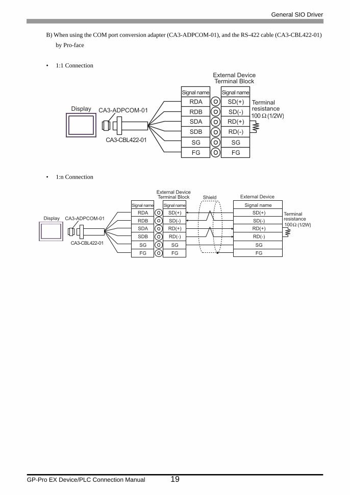
B) When using the COM port conversion adapter (CA3-ADPCOM-01), and the RS-422 cable (CA3-CBL422-01)
by Pro-face
• 1:1 Connection
• 1:n Connection
CA3-ADPCOM-01Display
CA3-CBL422-01
External DeviceTerminal Block
Signal name
RDA
RDB
SDA
SDB
SG
Signal name
SD(+)
SD(-)
RD(+)
RD(-)
SG
100 Ω (1/2W)
Terminalresistance
FG FG
CA3-ADPCOM-01Display
CA3-CBL422-01
External DeviceTerminal Block
Signal name
RDA
RDB
SDA
SDB
SG
Signal name
SD(+)
SD(-)
RD(+)
RD(-)
SG
FG FG
External Device
Signal name
SD(+)
SD(-)
RD(+)
RD(-)
SG
Ω
Terminalresistance
100
FG
(1/2W)
Shield

General SIO Driver
GP-Pro EX Device/PLC Connection Manual 20
C) When using a user-created cable
• 1:1 Connection
• 1:n Connection
• The termination resistor varies depending on the External Device. Refer to your External Device manual for details.
Shield External Device
Signal name
SD(+)
SD(-)
RD(+)
RD(-)
SG
Terminalresistance
Signal name
SDA3
RDB2
SG5
4 ERA
SDB
ERB
7
9
CSB6
RDA1
CSA8
DisplayD-Sub 9 Pin (socket)
Pin
Display
Terminalresistance
FG
Shield External Device
Signal name
SD(+)
SD(-)
RD(+)
RD(-)
SG
Terminalresistance
Signal name
SDA3
RDB2
SG5
4 ERA
SDB
ERB
7
9
CSB6
RDA1
CSA8
Pin
Display
FG
Shield External Device
Signal name
SD(+)
SD(-)
RD(+)
RD(-)
SG
Terminalresistance
FG
DisplayD-Sub 9 Pin (socket)

General SIO Driver
GP-Pro EX Device/PLC Connection Manual 21
D) When using the online adapter (CA4-ADPONL-01), the terminal block conversion adapter (CA3-ADPTRM-
01) by Pro-face, and a user-created cable
• 1:1 Connection
• 1:n Connection
CA4-ADPONL-01
CA3-ADPTRM-01
Display
Display
Terminal Block External Device
Signal name
SD(+)
SD(-)
RD(+)
RD(-)
SG
User-created cable
Signal name
RDB
SDB
SG
TRM
RDA
SDAΩ (1/2W)
Terminalresistance
100
FG
Shield
External Device
Signal name
SD(+)
SD(-)
RD(+)
RD(-)
SG
Ω
Terminalresistance
100
FG
CA4-ADPONL-01
CA3-ADPTRM-01
Display
Display
Terminal Block External Device
Signal name
SD(+)
SD(-)
RD(+)
RD(-)
SG
User-created cable
Signal name
RDB
SDB
SG
TRM
RDA
SDA
FG
(1/2W)
Shield Shield

General SIO Driver
GP-Pro EX Device/PLC Connection Manual 22
E) When using the online adapter (CA4-ADPONL-01), and the RS-422 cable (CA3-CBL422-01) by Pro-face
• 1:1 Connection
• 1:n Connection
CA4-ADPONL-01Display
CA3-CBL422-01
External DeviceTerminal Block
Signal name
RDA
RDB
SDA
SDB
SG
Signal name
SD(+)
SD(-)
RD(+)
RD(-)
SG
100 Ω (1/2W)
Terminalresistance
FG FG
CA4-ADPONL-01Display
CA3-CBL422-01
External DeviceTerminal Block
Signal name
RDA
RDB
SDA
SDB
SG
Signal name
SD(+)
SD(-)
RD(+)
RD(-)
SG
FG FG
External Device
Signal name
SD(+)
SD(-)
RD(+)
RD(-)
SG
Ω
Terminalresistance
100
FG
(1/2W)
Shield
General SIO Driver
GP-Pro EX Device/PLC Connection Manual 23
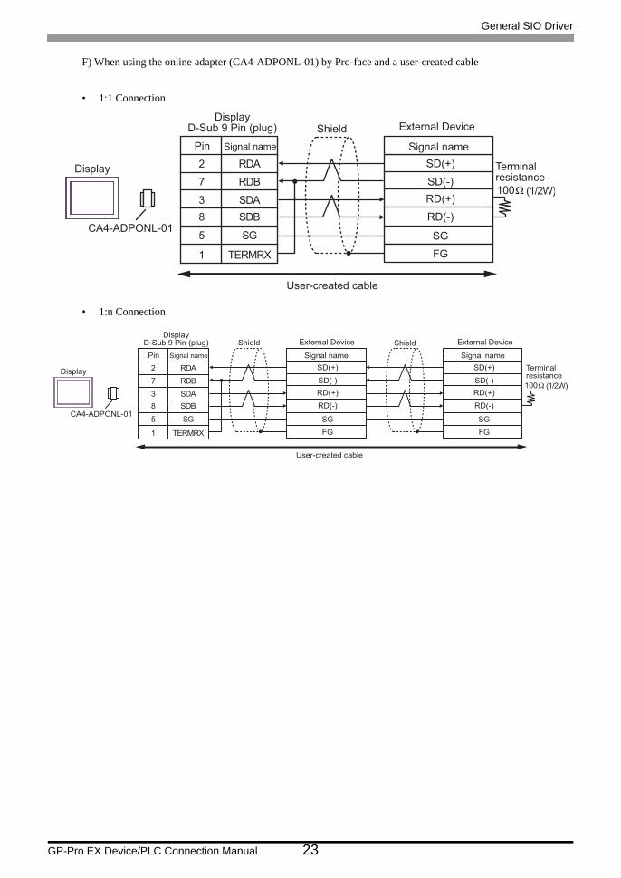
F) When using the online adapter (CA4-ADPONL-01) by Pro-face and a user-created cable
• 1:1 Connection
• 1:n Connection
CA4-ADPONL-01
Display
User-created cable
Signal name
RDA
SDB
SG
SDA
TERMRX
RDB
Pin
2
8
5
3
1
7
External Device
Signal name
SD(+)
SD(-)
RD(+)
RD(-)
SG
Ω (1/2W)
Terminalresistance
100
FG
ShieldDisplay
D-Sub 9 Pin (plug)
CA4-ADPONL-01
Display
User-created cable
Signal name
RDA
SDB
SG
SDA
TERMRX
RDB
Pin
2
8
5
3
1
7
DisplayD-Sub 9 Pin (plug) External Device External DeviceShield
Signal name
SD(+)
SD(-)
RD(+)
RD(-)
SG
Terminalresistance
FG
Signal name
SD(+)
SD(-)
RD(+)
RD(-)
SG
FG
Ω (1/2W)100
Shield

General SIO Driver
GP-Pro EX Device/PLC Connection Manual 24
Cable Diagram 3
Display(Connection Port)
Cable Remarks
GP*1 (COM1)AGP-3302B (COM2)LT (COM1)ST*2 (COM2)
*1 All GP models except AGP-3302B
*2 All ST models except AST-3211A
A
COM port conversion adapter by Pro-faceCA3-ADPCOM-01
+Terminal block conversion adapter by Pro-face
CA3-ADPTRM-01+
User-created cable
B User-created cable
GP*3 (COM2)
*3 All GP models except the GP-3200 Series and AGP-3302B
C
Online adapter by Pro-faceCA4-ADPONL-01
+Terminal block conversion adapter by Pro-face
CA3-ADPTRM-01+
User-created cable
D
Online adapter by Pro-faceCA4-ADPONL-01
+User-created cable
IPC*4
*4 Only a COM port that can communicate with RS-422/485 (2-wire) can be used. IPC COM Port (page 6)
E
COM port conversion adapter by Pro-faceCA3-ADPCOM-01
+Terminal block conversion adapter by Pro-face
CA3-ADPTRM-01+
User-created cable
F User-created cable
• The RS-422/485 cable length is normally 1000m or less, depending on the External Device. Refer to your External Device manual for details.
• The connection method and termination resistance depends on the External Device.• The termination resistance on the Display is not isolated.
General SIO Driver
GP-Pro EX Device/PLC Connection Manual 25
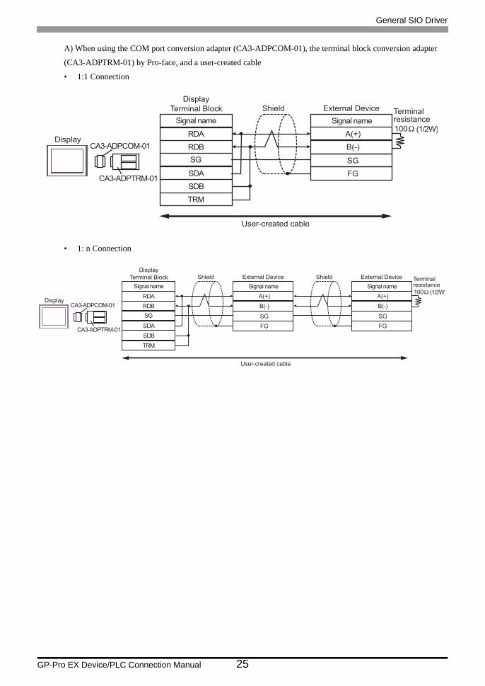
A) When using the COM port conversion adapter (CA3-ADPCOM-01), the terminal block conversion adapter
(CA3-ADPTRM-01) by Pro-face, and a user-created cable
• 1:1 Connection
• 1: n Connection
RDB
SDB
SG
TRM
CA3-ADPCOM-01
CA3-ADPTRM-01
RDA
SDA
A(+)
B(-)
User-created cable
External Device
Signal name
SG
Display
Display
Terminal Block
Signal name
Shield
FG
Ω (1/2W)
Terminalresistance
100
RDB
SDB
SG
TRM
CA3-ADPCOM-01
CA3-ADPTRM-01
RDA
SDA
A(+)
B(-)
User-created cable
External Device
Signal name
SG
Display
Display
Terminal Block
Signal name
Shield
FG
A(+)
B(-)
External Device
Signal name
SG
Shield
FG
Ω (1/2W)
Terminalresistance
100

General SIO Driver
GP-Pro EX Device/PLC Connection Manual 26
B) When using a user-created cable
• 1:1 Connection
• 1: n Connection
• The termination resistor varies depending on the External Device. Refer to your External Device manual for details.
Terminalresistance
Signal name
SDA3
RDB2
SG5
4 ERA
SDB
ERB
7
9
CSB6
RDA1
CSA8
DisplayD-Sub 9 Pin (socket)
Pin
Display
A(+)
B(-)
External Device
Signal name
SG
Shield
FG
Terminalresistance
Terminalresistance
Signal name
SDA3
RDB2
SG5
4 ERA
SDB
ERB
7
9
CSB6
RDA1
CSA8
Pin
Display
A(+)
B(-)
External Device
Signal name
SG
Shield
FG
A(+)
B(-)
External Device
Signal name
SG
Shield
FG
Terminalresistance
DisplayD-Sub 9 Pin (socket)

General SIO Driver
GP-Pro EX Device/PLC Connection Manual 27
C) When using the online adapter (CA4-ADPONL-01), the terminal block conversion adapter (CA3-ADPTRM-
01) by Pro-face, and a user-created cable
• 1:1 Connection
• 1: n Connection
RDB
SDB
SG
TRM
CA4-ADPONL-01
CA3-ADPTRM-01
RDA
SDA
A(+)
B(-)
User-created cable
External Device
Signal name
SG
Display
Display
Terminal Block
Signal name
Shield
FG
Ω (1/2W)
Terminalresistance
100
RDB
SDB
SG
TRM
CA4-ADPONL-01
CA3-ADPTRM-01
RDA
SDA
A(+)
B(-)
User-created cable
External Device
Signal name
SG
Display
Display
Terminal Block
Signal name
Shield
FG
A(+)
B(-)
External Device
Signal name
SG
Shield
FG
Ω (1/2W)
Terminalresistance
100

General SIO Driver
GP-Pro EX Device/PLC Connection Manual 28
D. When using the online adapter (CA4-ADPONL-01) by Pro-face, and a user-created cable
• 1:1 Connection
• 1: n Connection
CA4-ADPONL-01
Display
User-created cable
Signal name
RDA
SDA
SDB
SG
TERMRX
RDB
Pin
2
3
8
5
1
7
DisplayD-Sub 9 Pin (plug)
A(+)
B(-)
External Device
Signal name
SG
Shield
FG
Ω (1/2W)
Terminalresistance
100
CA4-ADPONL-01
Display
User-created cable
Signal name
RDA
SDA
SDB
SG
TERMRX
RDB
Pin
2
3
8
5
1
7
DisplayD-Sub 9 Pin (plug)
A(+)
B(-)
External Device
Signal name
SG
Shield
FG
A(+)
B(-)
External Device
Signal name
SG
Shield
FG
Ω (1/2W)
Terminalresistance
100

General SIO Driver
GP-Pro EX Device/PLC Connection Manual 29
E) When using the COM port conversion adapter (CA3-ADPCOM-01), the terminal block conversion adapter
(CA3-ADPTRM-01) by Pro-face, and a user-created cable
• 1:1 Connection
• 1: n Connection
RDB
SDB
SG
TRM
CA3-ADPCOM-01
CA3-ADPTRM-01
RDA
SDA
A(+)
B(-)
User-created cable
External Device
Signal name
SG
Display
Display
Terminal Block
Signal name
Shield
FG
Ω (1/2W)
Terminalresistance
100
RDB
SDB
SG
TRM
CA3-ADPCOM-01
CA3-ADPTRM-01
RDA
SDA
A(+)
B(-)
User-created cable
External Device
Signal name
SG
Display
Display
Terminal Block
Signal name
Shield
FG
A(+)
B(-)
External Device
Signal name
SG
Shield
FG
Ω (1/2W)
Terminalresistance
100

General SIO Driver
GP-Pro EX Device/PLC Connection Manual 30
F) When using a user-created cable
• 1:1 Connection
• 1: n Connection
• The termination resistor varies depending on the External Device. Refer to your External Device manual for details.
Terminalresistance
Signal name
NC3
DATA -2
SG5
4 ERA
NC
ERB
7
9
CSB6
DATA+1
CSA8
DisplayD-Sub 9 Pin (socket)
Pin
Display
A(+)
B(-)
External Device
Signal name
SG
Shield
FG
Terminalresistance
Terminalresistance
Signal name
NC3
DATA -2
SG5
4 ERA
NC
ERB
7
9
CSB6
DATA+1
CSA8
Pin
Display
A(+)
B(-)
External Device
Signal name
SG
Shield
FG
A(+)
B(-)
External Device
Signal name
SG
Shield
FG
Terminalresistance
DisplayD-Sub 9 Pin (socket)
General SIO Driver
GP-Pro EX Device/PLC Connection Manual 31
7 Supported Devices
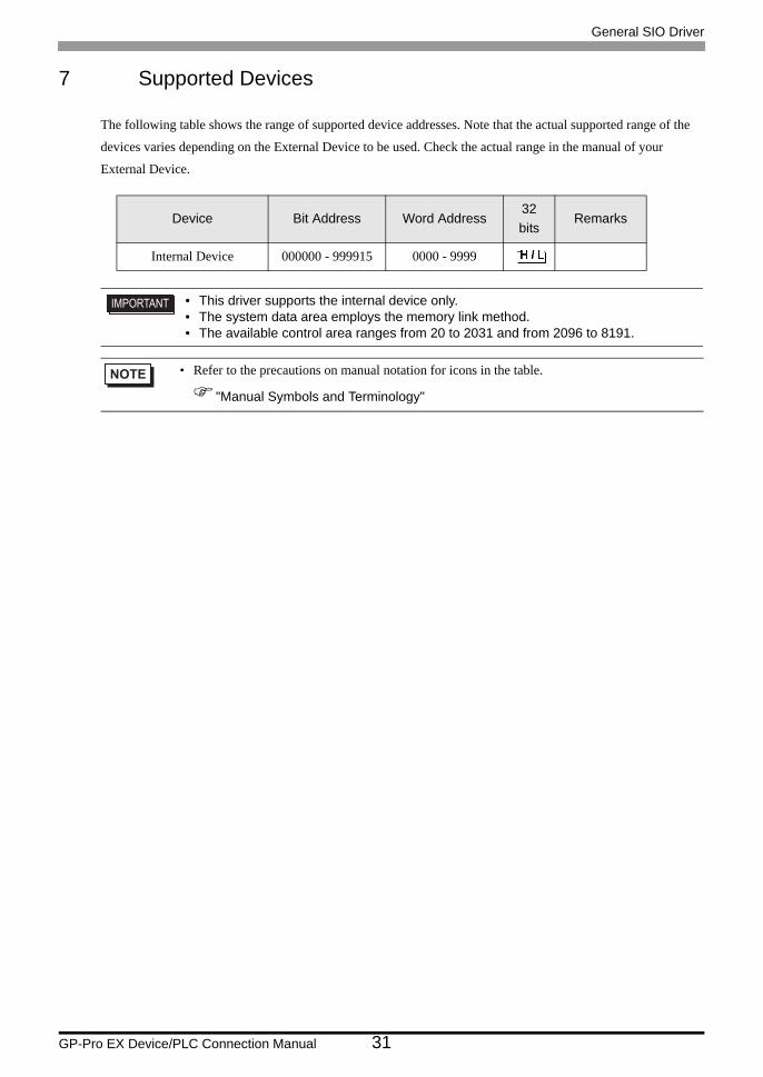
The following table shows the range of supported device addresses. Note that the actual supported range of the
devices varies depending on the External Device to be used. Check the actual range in the manual of your
External Device.
Device Bit Address Word Address32bits
Remarks
Internal Device 000000 - 999915 0000 - 9999
• This driver supports the internal device only.• The system data area employs the memory link method.• The available control area ranges from 20 to 2031 and from 2096 to 8191.
• Refer to the precautions on manual notation for icons in the table.
"Manual Symbols and Terminology"

General SIO Driver
GP-Pro EX Device/PLC Connection Manual 32
8 Device Code and Address Code
Use device code and address code if you select "Device Type & Address" for the address type in data display or
other devices.
Device Device Name Device Code (HEX) Address Code
Internal Device - 0000 Word address

General SIO Driver
GP-Pro EX Device/PLC Connection Manual 33
9 Error Messages
Error messages are displayed on the Display screen as follows: "No. : Device Name: Error Message (Error
Occurrence Area)". Each description is shown below.
Display Examples of Error Messages
"RHAA035: PLC1: Error has been responded for device write command (Error Code: 1[01H])"
Item Description
No. Error number
Device Name Name of the External Device where an error has occurred. Device/PLC name is the title of the External Device set with GP-Pro EX. (Initial value [PLC1])
Error Messages Displays messages related to an error that has occurred.
Error Occurrence Area
Displays the IP address or device address of the External Device where an error has occurred, or error codes received from the External Device.
• Received error codes are displayed as "Decimal [Hex]".• Device addresses are displayed as "Address: Device address".• IP addresses are displayed as "IP address (Decimal): MAC address (Hex)".
• Refer to your External Device manual for details on received error codes.• Refer to "When an error is displayed (Error Code List)" in "Maintenance/Troubleshooting Manual"
for details on the error messages common to the driver.
General SIO Driver
GP-Pro EX Device/PLC Connection Manual 34
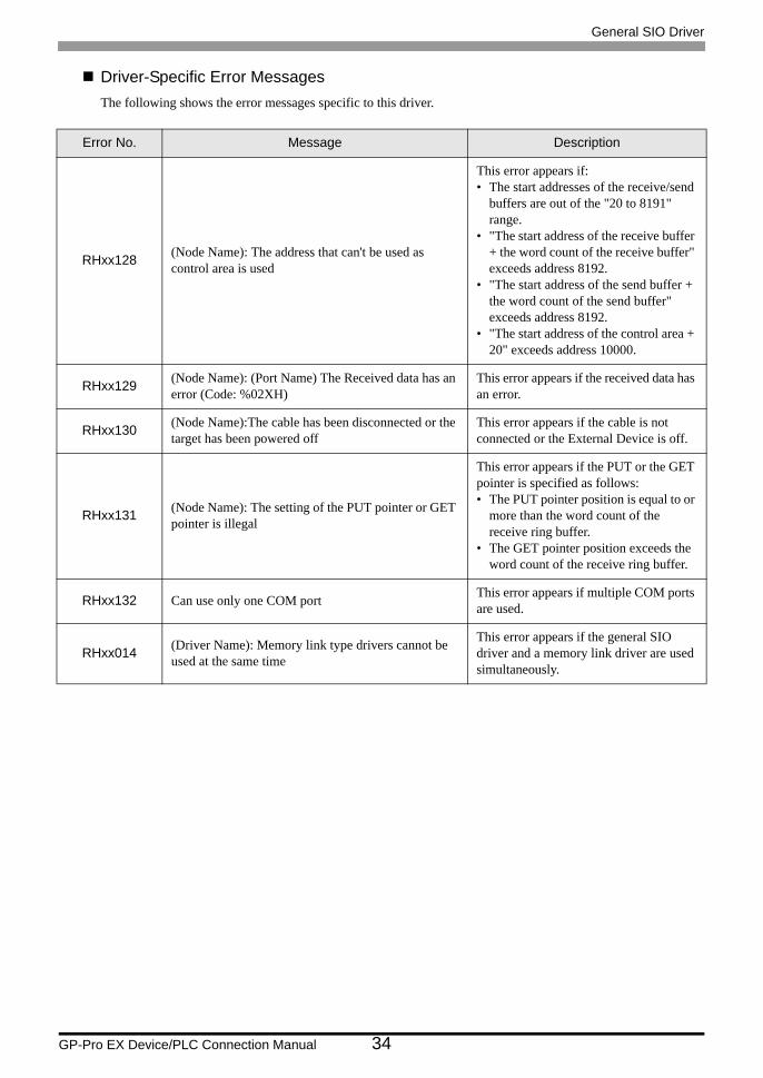
Driver-Specific Error MessagesThe following shows the error messages specific to this driver.
Error No. Message Description
RHxx128 (Node Name): The address that can't be used as control area is used
This error appears if:• The start addresses of the receive/send
buffers are out of the "20 to 8191" range.
• "The start address of the receive buffer + the word count of the receive buffer" exceeds address 8192.
• "The start address of the send buffer + the word count of the send buffer" exceeds address 8192.
• "The start address of the control area + 20" exceeds address 10000.
RHxx129 (Node Name): (Port Name) The Received data has an error (Code: %02XH)
This error appears if the received data has an error.
RHxx130 (Node Name):The cable has been disconnected or the target has been powered off
This error appears if the cable is not connected or the External Device is off.
RHxx131 (Node Name): The setting of the PUT pointer or GET pointer is illegal
This error appears if the PUT or the GET pointer is specified as follows:• The PUT pointer position is equal to or
more than the word count of the receive ring buffer.
• The GET pointer position exceeds the word count of the receive ring buffer.
RHxx132 Can use only one COM port This error appears if multiple COM ports are used.
RHxx014 (Driver Name): Memory link type drivers cannot be used at the same time
This error appears if the general SIO driver and a memory link driver are used simultaneously.

General SIO Driver
GP-Pro EX Device/PLC Connection Manual 35
10 Direct Communication Function
Using the Display's scripts, this driver creates data in the Display's memory table, supporting the function that
allows communication through the SIO. This is called "Direct Communication Function".
10.1 Memory Table
The following shows the Display's memory table map.
: Indicates areas that this protocol uses.
a: Start address of the control area
0 System data area19 "10.4 System Data Area" (page 42)20 User area
a+0 Receive-function control area
"10.2 Receive-function Control Area" (page 36)a+1a+2a+3a+4a+5a+6
a+9a+10 Send-function control area
"10.3 Send-function Control Area" (page 39)a+11a+12a+13a+14a+15a+16a+17a+18a+19
a+20 User area
20312032 Special relay
"10.5 Special Relay" (page 45)20472048 Reserved area
20952096 User area
81918192
9999
General SIO Driver
GP-Pro EX Device/PLC Connection Manual 36
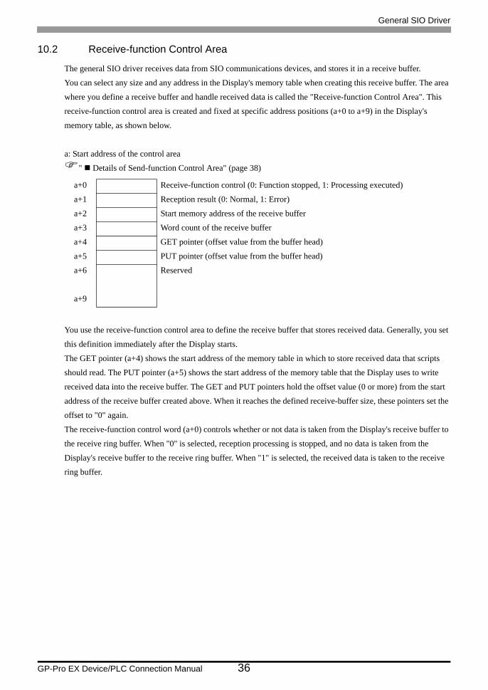
10.2 Receive-function Control Area
The general SIO driver receives data from SIO communications devices, and stores it in a receive buffer.
You can select any size and any address in the Display's memory table when creating this receive buffer. The area
where you define a receive buffer and handle received data is called the "Receive-function Control Area". This
receive-function control area is created and fixed at specific address positions (a+0 to a+9) in the Display's
memory table, as shown below.
a: Start address of the control area
" Details of Send-function Control Area" (page 38)
You use the receive-function control area to define the receive buffer that stores received data. Generally, you set
this definition immediately after the Display starts.
The GET pointer (a+4) shows the start address of the memory table in which to store received data that scripts
should read. The PUT pointer (a+5) shows the start address of the memory table that the Display uses to write
received data into the receive buffer. The GET and PUT pointers hold the offset value (0 or more) from the start
address of the receive buffer created above. When it reaches the defined receive-buffer size, these pointers set the
offset to "0" again.
The receive-function control word (a+0) controls whether or not data is taken from the Display's receive buffer to
the receive ring buffer. When "0" is selected, reception processing is stopped, and no data is taken from the
Display's receive buffer to the receive ring buffer. When "1" is selected, the received data is taken to the receive
ring buffer.
a+0 Receive-function control (0: Function stopped, 1: Processing executed)
a+1 Reception result (0: Normal, 1: Error)
a+2 Start memory address of the receive buffer
a+3 Word count of the receive buffer
a+4 GET pointer (offset value from the buffer head)
a+5 PUT pointer (offset value from the buffer head)
a+6 Reserved
a+9

General SIO Driver
GP-Pro EX Device/PLC Connection Manual 37
Receive BufferThe following shows the state in which a receive buffer is created and data is received.
The following figure shows the state in which a ring buffer is created from memory table address a+50 using 6
words, and 2 bytes ("A", "B") are received.
The Display's receive function stores received data at the PUT pointer position every time 1 byte is received, and
then moves the PUT pointer forward to the next address.
Scripts read out data from the GET pointer position, and moves the GET pointer forward according to the amount
of the read-out data. Received data is stored per byte in the lower bytes of each address in the memory table
(word: 16-bit length).
The PUT pointer, controlled by the Display, shows the write position for the next piece of received data.
When the PUT pointer reaches the end address (a+55) of the receive buffer, it attempts to store data in the start
address (a+50) again. However, the GET pointer position is never exceeded. (Data cannot be overwritten where
readout is not complete.) This means you need to move the GET pointer forward appropriately after scripts read
out the received data. If the GET pointer is not repositioned, and received data cannot be written into the Display's
receive buffer for some time, the receive buffer may overflow.
Example: when the start address of the control area is 1900 Address Memory content
Received data is stored per byte in the lower bytes of each address in the memory table (word: 16-bit
length).
1900 0001h Receive-function control word
1901 0 Reception result
1902 1950 Start address of the receive ring buffer
1903 6 Word count of the receive ring buffer
1904 0 GET pointer
1905 2 PUT pointer
1950 00h "A" (41h)
1951 00h "B" (42h) Receive ring buffer
1952 6 words
1953
1954
1955
Bit position15 8 7 0

General SIO Driver
GP-Pro EX Device/PLC Connection Manual 38
Details of Send-function Control Areaa: Start address of the control area
System area
addressName
Update responsibility*1
(Trigger)
*1 To ensure this function operates properly, the "Update responsibility" shows what item is responsiblefor updating data.Display: The Display performs updates.Scripts: A D-Script/ladder program using this function is necessary in order to perform updates.
Description
a+0 Receive-function control word Scripts
0: Receive-function stopped1: Receive-function enabledData is taken from the Display's receive buffer to the receive ring buffer. Scripts update the data.
a+1 Reception result Display
Indicates reception results using bits.1: Framing error2: Parity error4: Overrun error8: Buffer overflowExcept 0: ErrorScripts write "0" in this area after an error is confirmed, and then the next piece of data is received.
a+2 Start memory address of the receive ring buffer Scripts
Set the memory table start address for the receive ring buffer.You can set this in any of the memory addresses (0 to 8191) as long as it is a user area other than a system data area or special relay.
a+3 Word count of the receive ring buffer Scripts
Set the word count of the receive buffer. (Match the word count specified here with the number of bytes that can be received.)Specify the word count that begins from the above start address. For ring buffers, you need to specify two or more words. (If you specify "0" or "1" , words cannot be received.)
a+4 GET pointer Scripts
The GET pointer indicates the address position of the next received data that scripts should read, and holds the offset value (0 or more) from the start address of the receive ring buffer. Scripts retrieve data from this pointer position. The position is then updated.
a+5 PUT pointer Display
The PUT pointer indicates the write position for data that the Display has received in its receive buffer. Whenever the Display receives data, this pointer is automatically updated.
a+6 Reserved: Reserved
a+9 Reserved
• Make sure that the definition regions for the receive buffers do not overlap those of send buffers or other system data areas of the Display. Overlapping definition regions may cause the system to malfunction.

General SIO Driver
GP-Pro EX Device/PLC Connection Manual 39
10.3 Send-function Control Area
This driver has a send buffer that temporarily stores send packets before sending data to SIO communications
devices. You can select any size and any address in the Display's memory table when creating this send buffer.
The area where to define a send buffer and handle data to be sent is called the "Send-function Control Area". This
send-function control area is created and fixed at specific address positions (a+10 to a+19) in the Display's
memory table, as shown below.
a: Start address of the control area
" Details of Send-function Control Area" (page 41)
A send buffer temporarily stores data that will be sent to the SIO. You can then run the Send command to send the
data in the buffer from the SIO.
First you specify the start address of the send buffer for its initial memory address (a+12). Then, after the
specified buffer has stored the data to be sent, you set the data bytes (a+13). When you write "1" into the send-
function control word (a+10) after a send packet is created, the packet is sent through the SIO.
After each of the processing commands is complete, the send-function control word automatically becomes "0".
a+10 Send-function control (0: Function stopped, 1: Processing executed)
a+11 Transmission result (0: Normal, Except 0: Error)
a+12 Start memory address of the send buffer
a+13 Number of data bytes to be sent
a+14 Reserved
a+19
Writing "1" into the send-function control word does not send packets if:• The range of the control area exceeds address 8192.• "The initial address of the receive ring buffer + the word count of the receive ring
buffer" exceeds address 8192.• "The initial address of the send buffer + the number of data bytes to be sent" exceeds
address 8192.• The GET or the PUT pointer position exceeds the receive ring buffer end.

General SIO Driver
GP-Pro EX Device/PLC Connection Manual 40
Send BufferThe following shows the state in which a send buffer is created and data is sent.
The following figure shows the state in which a send buffer is created from memory table address a+60, and 3
bytes ("A", "B", "C") are sent.
A send buffer stores data, beginning with the start address specified. You specify the byte size (occupied memory
table area size) for the data length. Note that data is stored per byte in the lower bytes of 1 word in the memory
table, and thus the byte size is equal to the number of words occupied in the memory table.
Example: when the start address of the control area is 1900 Address Memory content
* Be sure to store the data to be sent per byte in the lower bytes of each address in the memory table
(word: 16-bit length).
1910 0001h Send-function control word
1911 0 Transmission result
1912 1960 Start memory address of the send buffer
1913 3 Number of data bytes to be sent
1960 00h "A" (41h)
1961 00h "B" (42h) Number of data bytes to be sent
1962 00h "C" (43h)
1963
1964
Bit position15 8 7 0

General SIO Driver
GP-Pro EX Device/PLC Connection Manual 41
Details of Send-function Control Areaa: Start address of the control area
System area
addressName
Update responsibility*1
(Trigger)
*1 To ensure this function operates properly, the "Update responsibility" shows what item is responsiblefor updating data.Display: The Display performs updates.Scripts: A D-Script/ladder program using this function is necessary in order to perform updates.
Description
a+10 Send-function control word Scripts
0: Function stopped (or processing completed)1: The send buffer sends data to the COM port.Scripts update the data.After the following processing is complete, the Display resets this area value to "0".
a+11 Transmission result Display
Indicates reception results using bits.1: Framing error2: Parity error4: Overrun error8: Buffer overflowExcept 0: ErrorScripts write "0" in this area after an error is confirmed, and then the next piece of data is received.
a+12Start address of the send buffer Scripts
Set the start memory address for the send buffer.You can set this in any of the Display's memory tables as long as you use a user area other than a system data area or special relay.
a+13 Number of data bytes to be sent Scripts
Set the send-buffer word count.(Set the number of bytes stored in the send buffer.)Specify the consecutive word count from the above start address.
a+14 Reserved: Reserved
a+19 Reserved
• Make sure that the definition regions for the send buffers do not overlap those of receive buffers or other system data areas of the Display. Overlapping definition regions may cause the system to malfunction.

General SIO Driver
GP-Pro EX Device/PLC Connection Manual 42
10.4 System Data Area
The system data area stores data necessary for the system's operation, such as the Display's screen control data
and error information. The following describes the system data area.
Address Description Function Bit Remarks
0000 Reserved
0001 Status*1
0, 1 Reserved
2 Printing*2
3 Setting value writing*3
4 to 7 Reserved
8 K-tag input error*4
9 Display 0: ON, 1: OFF*5
10 Backlight burnout detected*6
11 Touch panel input error*7
12 to 15 Reserved
0002 Reserved
0003
Error statusWhen an error occurs in the Display, the corresponding bit turns on.The bit is kept ON until either the power is turned off and then turned on again or the off-line mode is switched back to active mode.
0, 1 Reserved
2 System ROM/RAM
3 Screen memory check sum
4 SIO framing
5 SIO parity
6 SIO overrun
7, 8 Reserved
9 Internal memory initialization required
10 Timer lock error
11 to 15 Reserved
0004 Clock data (year)
"Year, Month, Day, Hour, and Minute" are each stored in two BCD digits.
0 to 7 Stores the last two digits of the year in two BCD digits.
8 to 15 Not used
0005 Clock data (month)0 to 7 Stores the month, from 01 to 12, in
two BCD digits.
8 to 15 Not used
0006 Clock data (day)0 to 7 Stores the day, from 01 to 31, in two
BCD digits.
8 to 15 Not used
0007 Clock data (hour)0 to 7 Stores the hour, from 00 to 23, in
two BCD digits.
8 to 15 Not used
0008 Clock data (minute)0 to 7 Stores the minute, from 00 to 59, in
two BCD digits.
8 to 15 Not used
0009 Reserved
Continued on next page.

General SIO Driver
GP-Pro EX Device/PLC Connection Manual 43
0010Interrupt output*8
(When touch is OFF)
If writing to a Word Switch (16 bit), when you take your finger off the Switch, the bottom 8 bits are output as an interrupt code. (Control code "FFh" will not be outputted.)
0011 Control*9
0 Backlight*10
1 Buzzer ON*11
2 Print started
3 Reserved
4 Buzzer sound*11 0: ON, 1:OFF
5 AUX output*11 0: ON, 1: OFF
6
The interrupt output when the display is switched from OFF to ON by pressing the touch panel.*12
(Interrupt code: ffh)0: Interrupt not output1: Interrupt output
7 to 10 Reserved
11 Hardcopy output*13
0: Displayed, 1: Output cancelled
12 to 15 Reserved
0012 Screen display ON/OFF*14
"FFFFh" turns off the screen display."0h" turns on the screen display. Values other than "FFFFh" and "0h" are used as "Reserved".
0013 Interrupt output*8 When writing to a Word Switch (16 bit), the lower 8 bits are output from the Display to the External Device as an interrupt code.
0014 Reserved
0015 Display screen No. Writing a screen number switches the display screen.
0 to 14 Switching screen Nos. 1 to 8999(For the BCD input, 1 to 1999)
15Forced screen switching(0: Normal, 1: Forced screen switching)
0016 Window control
0 Display 0: OFF, 1: ON
1 Changing the order of overlapping windows 0: Enabled, 1: Disabled
2 to 15 Reserved
0017 Window registration No.
The registration number of the global window selected by indirect designation.(BIN or BCD)
0018Window display position(X-coordinate data) The display position of the global window selected by indirect designation.
(BIN or BCD)0019
Window display position(Y-coordinate data)
*1 Status• Monitor only the necessary bits.
• The "reserved" bits may be used for the Display's system maintenance. You do not need to turn them on/off.
*2 The bit turns on during printing. If you switch to off-line mode while this bit is on, the printout may be corrupted.
*3 This bit is reversed each time a write occur from a Data Display (Setting Value Input).
Address Description Function Bit Remarks

General SIO Driver
GP-Pro EX Device/PLC Connection Manual 44
*4 This bit turns on if an alarm is set for the Data Display that you are currently inputting and you input a valueoutside of the alarm range. When you input a value inside the alarm range or the screen is switched, this bit turnsoff.
*5 You can detect "Display ON/OFF" from External Devices. This bit also changes if:
(1) FFFFh is written to the system data area's "Display ON/OFF" (LS0009 when link type is used.), and thedisplay is turned off (bit 9 = 1).
(2) The standby time elapses and the display automatically turns off. (bit 9 =1)
(3) The display is switched from off to on through screen switching etc.(bit 9 = 0)
(4) This bit does not change in "Backlight OFF" (bit 0) in the system area's "Control".
*6 When a backlight burnout is detected, this bit turns on. Note that this is available only for models with abacklight.
*7 If the same part of a touch panel display is continuously used over a specific period of time, this bit turns on.
*8 Do not write control codes from 00 to 1F into addresses 10 and 13. Communications may be disabled.
*9 Reserved bits may be used for maintenance. Be sure to turn them off.
*10 When this bit turns on, the backlight turns off (the LCD is left as is). When this bit turns off, the backlight turnson.If you turn on the "Backlight OFF" bit in the system area's control range, only the backlight turns off, with theLCD left as is. The touch switches specified on the screen remain active as well.In most cases, use "Screen display ON/OFF" to turn off the screen display.
*11 When bit 1 (Buzzer ON) in the control range is on, the output destinations are as follows:
Buzzer sound: While bit 1 in the control range is on, the Display's buzzer sounds.AUX output: While bit 1 in the control range is on, the buzzer output from the AUX is turned on.
*12 An interrupt is output only when you use the touch panel to turn on the display.
*13 By turning on bit 11 (Hardcopy output) in the control range, you can cancel the display printing in progress.• After the printing is cancelled, bit 11 in the control range is not turned off automatically. Be sure to monitor
the "Printing" under "Status" to turn it off.
• While bit 11 in the control range is turned on, the print function is not available and any print jobs are
cancelled. If printing is cancelled while underway, a single line of data on the screen is printed, and then
printing stops. Data already sent to the printer's buffer is not cleared.
*14 If you use the system data area's "Screen display ON/OFF" to turn on the display, touching the screen after thedisplay is turned off turns it back on again.
• Addresses "0", "2", "9", and "14" are reserved. Do not write data to them.• Because addresses "3", "12", "13", and "15" are used for system control, do not use
tags to display data.• Because addresses "12", "13", and "15" are controlled in units of words, you cannot
write bits.• When you write "FFFFh" into address 12, the screen display instantly turns off. When
you write "0000h" into address 12, the screen display turns off during the standby-mode time specified in the initial settings for the Display's offline mode.
• Do not write control codes from 00 to 1F into addresses 10 and 13. Otherwise, communications may be disabled.

General SIO Driver
GP-Pro EX Device/PLC Connection Manual 45
10.5 Special Relay
The following describes the special relay.
• Common relay information (2032)
• Base screen information (2033)
2032 Common relay information
2033 Base screen information
2034 Reserved
2035 1-second binary counter
2036 Tag scan time
2037 Reserved
2038 Tag scan counter
2039 Communication error code
2040 Reserved
2047
Bit Description
0 Reserved
1 Turns on when the screen (base/window) is switched on until the tag processing is complete.
2 Reserved
3 Turns on while the initial screen number is displayed immediately after power is turned on.
4 Always on
5 Always off
6 Turns on if the backup SRAM data is deleted.(Available only for Displays with backup SRAM)
7 Turns on if a BCD error occurs when the D-script is used.
8 Turns on if a zero-operation error occurs when the D-script is used.
9 Turns on when filing data fails to be transferred to the backup SRAM.
10
Turns ON when filing data transferred according to the Control Word Address could not be transferred from External Device. Also, if transferring between the External Device by means of a Special Data Display, when there is a Transfer Complete Bit Address, turns ON when data could not be transferred from External Device Area, or External Device SRAM.
11 Turns on while the File Items Display device transfers filing data between the SRAM and LS area.
12 Turns on if a communication error occurs in reading out memcpy() and the assigned address offset when the D-script is used. After the data is read successfully, this bit turns off.
13 to 15 Reserved
Bit Description
1 Turns on when the base screen is switched on until the tag processing is complete.
General SIO Driver
GP-Pro EX Device/PLC Connection Manual 46
• 1-second binary counter (2035)Increments the count per second immediately after power-on. Data is binary.
• Tag scan time (2036)
Indicates the period from when the system starts processing the first tag specified on the display screen until it
finishes processing the last tag. Data is stored in binary format, in units of milliseconds (ms). The data is
updated after all the target tags are processed. The default value of the data is "0". Note that the value has an
error of ±10ms.
• Tag scan counter (2038)
Increments the count each time the system finishes processing all the tags specified on the display screen.
Data is binary.
• The special relay is not write-protected. Be sure not to turn it off using tags, etc.

General SIO Driver
GP-Pro EX Device/PLC Connection Manual 47
11 Sample Program
The following provides an example of the procedure for sending and receiving data, and shows its sample script.
<System Configuration>
<Program Overview>
This sample program performs the following communications:
1. Sends 3-byte data (ABC) to the External Device.
2. Receives 2 bytes of the data sent.
<Example of Procedure for Sending/Receiving Data>
The following provides an example of a procedure where the Display sends a command to and receives a response
from the External Device.
1. Setting the receive-function control area
(1) Clear the reception result.
(2) Set the start address for the receive ring buffer.
(3) Set the word count of the receive ring buffer.
(4) Correct the gap of the GET and PUT pointers (to ensure they are indicating valid data locations).
(5) Set the receive-function control word (0x0001: Reception enabled).
2. Setting the send-function control area
(1) Clear the transmission result.
(2) Set the start address for the send buffer.
(3) Set the send-function control word.
3. Creating and sending data
(1) Create data to be sent.
(2) Set the send-function control word (0x0001: Transmission enabled).
Display External Device

General SIO Driver
GP-Pro EX Device/PLC Connection Manual 48
<Sample Script>
The following shows a sample script, based on the states described in " Receive Buffer" (page 37) and " Send
Buffer" (page 40).
Here is a memory map in use, with the start address of the control area set to 1900.
Address Memory content1900 0001h Receive-function control word1901 0 Reception result1902 1950 Start address of the receive ring buffer1903 6 Word count of the receive ring buffer1904 6 GET pointer1905 2 PUT pointer
: :1910 0000h Send-function control word1911 0 Transmission result1912 1960 Start address of the send buffer1913 3 Number of data bytes to be sent
: :Bit position
15 8 7 01950 00h "A" (41h) Receive ring buffer1951 00h "B" (42h) 6 words1952 1953 1954 1955
: :
15 8 7 01960 00h "A" (41h)1961 00h "B" (42h) Send buffer1962 00h "C"(43h)1963 1964

General SIO Driver
GP-Pro EX Device/PLC Connection Manual 49
1. Open processing (Setting the receive-function control area)
• Trigger condition
• Execution formula
// Initializing the control area
// Setting the receive-function control area -----[w:[#MEMLINK]1901] = 0 // Reception result cleared[w:[#MEMLINK]1902] = 1950 // Start address of the receive buffer[w:[#MEMLINK]1903] = 6 // Word count of the receive buffer[w:[#MEMLINK]1904] = 6 // GET pointer[w:[#MEMLINK]1905] = 0 // PUT pointer
// Enabling reception[w:[#MEMLINK]1900] = 1 // Reception of the receive-control word enabled
// Setting the send-function control area -----[w:[#MEMLINK]1911] = 0 // Transmission result cleared[w:[#MEMLINK]1912] = 1960 // Start address of the send buffer[w:[#MEMLINK]1913] = 3 // Word count of the send buffer

General SIO Driver
GP-Pro EX Device/PLC Connection Manual 50
2. Transmission processing (Creating and sending data)
• Trigger condition
• Execution formula
// Creating and sending packets
if ([w:[#MEMLINK]1901]==0)[//Creating packets -----[w:[#MEMLINK]1960] = 0x41 // 'A'[w:[#MEMLINK]1961] = 0x42 // 'B'[w:[#MEMLINK]1962] = 0x43 // 'C'
// Sending packets -----[w:[#MEMLINK]1910] = 1 // Setting the send-function control word -----]endif