general specification for broadcast reception installation ... · general specification for...
TRANSCRIPT
GENERAL SPECIFICATION
FOR
BROADCAST RECEPTION INSTALLATION
IN
GOVERNMENT BUILDINGS
OF
THE HONG KONG SPECIAL ADMINISTRATIVE REGION
2007 EDITION
ARCHITECTURAL SERVICES DEPARTMENT THE GOVERNMENT OF THE HONG KONG SPECIAL ADMINISTRATIVE REGION


PREFACE This General Specification aims to lay down the technical requirements of materials and equipment, the standards of workmanship, the requirements on testing and commissioning as well as requirements on document submissions for Broadcast Reception installation in Government Buildings of the Hong Kong Special Administrative Region (HKSAR). The 2007 edition of this General Specification was developed based on its 2001 edition by the Electrical Group ‘C’ SSG that was established under the Building Services Branch, Technical Information and Research & Development Committee. Apart from the adoption of a new arrangement which gives the document a more compact and well defined structure, this new edition comprises revisions to incorporate updated international standards and covers technological developments which find applications in Hong Kong. The other emphasis is on green initiatives, e.g. reduction of construction waste and enhancement of client satisfaction on completed projects. This is in line with the department’s endeavour to reduce the environmental burden on our neighbours and help to preserve common resources while improving the quality of our service. With the benefit of information technology, electronic version of this new edition is to be viewed on and free for download from the Architectural Services Department (ArchSD) Internet homepage. As part of the Government’s efforts to limit paper consumption, hard copies of this General Specification will not be put up for sale. The draft of this edition has been circulated to stakeholders within and external to the Government before finalization. Nevertheless, the Architectural Services Department welcomes comments on its contents at anytime since the updating of this General Specification is a continuous process for the inclusion of any developments that can help meeting the needs of our community.

DISCLAIMER
This General Specification is solely compiled for a broadcast reception installation carried out for or on behalf of the ArchSD in Government buildings of the HKSAR. There are no representations, either expressed or implied, as to the suitability of this General Specification for purposes other than that stated above. Users who choose to adopt this General Specification for their works are responsible for making their own assessments and judgment of all information contained here. The ArchSD does not accept any liability and responsibility for any special, indirect or consequential loss or damage whatsoever arising out of or in connection with the use of this General Specification or reliance placed on it. The materials contained in this document may not be pertinent or fully cover the extent of the installation in non-government buildings and there is no intimated or implied endorsement of the sales, supply and installation of the materials and equipment specified in this General Specification within the territory of the HKSAR.

Table of Contents Page 1 of 6
BRI_GS2007 Edition
TABLE OF CONTENTS
PART A - SCOPE AND GENERAL REQUIREMENTS
SECTION A1 SCOPE OF SPECIFICATION
A1.1 Installation to comply with this General Specification A1.2 Scope of the Works A1.3 Terms and Definitions A1.4 Singular and Plural
SECTION A2 STATUTORY OBLIGATIONS AND OTHER REGULATIONS
A2.1 Statutory Obligations and Other Requirements A2.1.1 Statutory Obligations A2.1.2 Other Requirements A2.1.3 Safety Requirements A2.1.4 Technical Standards
A2.2 Case of Conflict
SECTION A3 EXECUTION OF WORKS
A3.1 The International System of Units (SI) A3.2 Programme of Works A3.3 Builder’s Work A3.4 Coordination of Contract Works A3.5 Cooperation with Other Contractors A3.6 Site Supervision A3.7 Sample Board A3.8 Advice of Order Placed A3.9 Record of Materials Delivery A3.10 Protection of Materials and Equipment
SECTION A4 DRAWINGS AND MANUALS
A4.1 Standard Drawings A4.2 Drawings in Electronic Format A4.3 Installation Drawings
A4.3.1 Drawing Submission Schedule A4.3.2 Size of Installation Drawings A4.3.3 Contents of Installation Drawings A4.3.4 Builder’s Work Drawings A4.3.5 Manufacturer’s Shop Drawings
A4.4 As-built Drawings A4.4.1 Submission of As-built Drawings A4.4.2 Size of As-built Drawings A4.4.3 Content of As-built Drawings A4.4.4 Framed Drawings

Table of Contents Page 2 of 6
BRI_GS2007 Edition
A4.5 Operation and Maintenance (O&M) Manual and User Manual A4.5.1 General A4.5.2 Presentation A4.5.3 Checking and Approval A4.5.4 Structure and Content of O&M Manual A4.5.5 Structure and Content of User Manual A4.5.6 Intellectual Property Rights

Table of Contents Page 3 of 6
BRI_GS2007 Edition
PART B - INSTALLATION METHODOLOGY
SECTION B1 BROADCAST RECEPTION (BR) SYSTEM DESIGN
B1.1 General B1.2 Only One Broadcast Reception System per Site B1.3 Selecting the Gain of TV and FM Aerials B1.4 Separate Down Leads for the TV and FM Signals B1.5 Selection of Amplifiers B1.6 Loss Allowance B1.7 Enclosure of Headend Circuit Components B1.8 Compatibility of Signal Adaptors/Set Top Boxes/Digital
Terrestrial Television Baseline Receivers
SECTION B2 SIGNAL LEVEL AT FM/TV/DATA TRIPLEX OUTLET
B2.1 Signal Levels B2.2 Permissible Different Signal Levels in an Outlet B2.3 Carrier to Noise Ratio B2.4 Mutual Isolation between Outlets B2.5 System Performance with Return Path
SECTION B3 TERRESTRIAL MASTER ANTENNA TELEVISION SYSTEM
B3.1 Terrestrial Aerials B3.2 Preamplifiers and Filters B3.3 Amplifiers B3.4 Frequency Converters B3.5 UHF Modulators B3.6 Splitters/Tee-Units B3.7 Coaxial Cables B3.8 FM/TV/Data Triplex Outlets B3.9 Fibre Optical Cable System
SECTION B4 SATELLITE MASTER ANTENNA TELEVISION SYSTEM
B4.1 SMATV System Installer Requirements B4.2 The SMATV System Requirements
B4.2.1 Antenna Location B4.2.2 Support for the Dish Antenna B4.2.3 Antenna Installation
B4.3 Feedhorn/Low Noise Amplifier (LNA)/Low Noise Block Down Converter (LNB)
B4.4 Satellite Receivers and Modulators
SECTION B5 ANCILLARY SYSTEM
B5.1 Conduits & Cable Trunkings B5.2 Power Supply

Table of Contents Page 4 of 6
BRI_GS2007 Edition
PART C - MATERIAL AND EQUIPMENT SPECIFICATION
SECTION C1 GENERAL
C1.1 General Requirement
SECTION C2 TERRESTRIAL MASTER ANTENNA TELEVISION SYSTEM
C2.1 Terrestrial Aerials C2.2 Preamplifiers and Filters
C2.2.1 Preamplifiers C2.2.2 TV Bandpass Preamplifiers C2.2.3 FM Bandpass Preamplifiers C2.2.4 TV Bandpass Filters C2.2.5 FM Bandpass Filters
C2.3 Amplifiers C2.3.1 Wideband Amplifiers C2.3.2 FM Channel Amplifiers with Processor C2.3.3 TV Channel Amplifiers with Processor with
Automatic Gain Control (AGC) Modules C2.4 Frequency Converters C2.5 UHF Modulators C2.6 Splitters/Tee-Units
C2.6.1 Splitters C2.6.2 Tee Units
C2.7 Coaxial Cables C2.8 FM/TV/Data Triplex Outlets C2.9 Fiber Optical Transmitter C2.10 Fiber Optical Transceiver with Return Path C2.11 Fiber Optical Splitter C2.12 Fiber Optical Cable
SECTION C3 SATELLITE MASTER ANTENNA TELEVISION SYSTEM
C3.1 System Requirements C3.2 The SMATV System Requirements
C3.2.1 Environment Operating Requirements C3.2.2 Electrical Specification C3.2.3 Mechanical Specifications C3.2.4 Feedhorn C3.2.5 Low Noise Amplifier (LNA)/Low Noise Block
Down Converter (LNB) C3.3 Satellite Receivers
C3.3.1 RF Signal C3.3.2 Video Parameters C3.3.3 Audio Parameters
C3.4 Satellite Amplifier C3.5 Splitter/Tee-Unit
C3.5.1 Splitters C3.5.2 Tee Units

Table of Contents Page 5 of 6
BRI_GS2007 Edition
SECTION C4 ANCILLARY SYSTEM
C4.1 Cable Trunking C4.2 Conduit and Accessories C4.3 Power Cable
PART D - INSPECTION, TESTING AND CONMISSIONING DURING CONSTRUCTION PERIOD
SECTION D1 GENERAL REQUIREMENT
D1.1 General Requirement
SECTION D2 ROUTINE INSPECTION
D2.1 Inspection of Materials and Equipment Delivered to Site D2.2 Visual Inspection of Installation D2.3 Inspection and Functional Test of Installed Works
SECTION D3 HANDOVER INSPECTION SECTION D4 TESTING & COMMISSIONING
D4.1 General D4.2 Testing and Commissioning Procedures

Table of Contents Page 6 of 6
BRI_GS2007 Edition
PART E - TRAINING, ATTENDANCE, INSPECTION, OPERATION
AND MAINTENANCE DURING MAINTENANCE PERIOD
SECTION E1 TRAINING TO USERS AND OPERATION AND MAINTENANCE AGENTS
E1.1 Particulars of Training Course and Training Schedule
SECTION E2 EMERGENCY SERVICES AND ATTENANCE TO FAULT
CALLS
E2.1 Requirements on Response Time E2.2 Monitoring Mechanism on Contractor’s Performance E2.3 Follow up Action after Emergency and Fault Cases
SECTION E3 INSPECTION, OPERATION AND MAINTENANCE DURING
MAINTENANCE REQUIREMENTS
E3.1 General Maintenance Requirements E3.2 Routine Half-Yearly Inspection, Testing and Maintenance E3.3 Final Inspection before the End of Maintenance Period E3.4 Taking Records in Log-Book
SECTION E4 COMPLETION OF OUTSTANDING AND DEFECTIVE WORKS ANNEX I ABBREVIATIONS ANNEX II LIST OF TECHNICAL STANDARDS QUOTED IN THIS
GENERAL SPECIFICATION ANNEX III TESTING INSTRUMENT REQUIRED FOR ACCEPTANCE
TESTS OF BROADCAST RECEPTION INSTALLATION ANNEX IV TYPICAL PROVISION OF BROADCAST RECEPTION
SYSTEM MAIN TRUNKS

PART A - SCOPE AND GENERAL REQUIREMENTS
SECTION A1
SCOPE OF SPECIFICATION
A1.1 INSTALLATION TO COMPLY WITH THIS GENERAL SPECIFICATION The broadcast reception installation shall comply with this General Specification which details the intrinsic properties (including materials and workmanship) of the installation, in so far as it is not overridden by the General Conditions of Contract, Special Conditions of Contract, Particular Specification for the Works, Drawings and/or written instructions of the Architect.
A1.2 SCOPE OF THE WORKS This General Specification, Particular Specification, Tender Equipment Schedule and Drawings detail the performance requirements of the Works. The Works to be carried out in accordance with this General Specification shall include the whole of the design for a broadcast reception installation only, installation and supply of all materials necessary to form a complete installation including any necessary tests, adjustments, commissioning and maintenance as prescribed and all other incidental sundry components together with the necessary labour for installing such components, for the proper operation of the installation. This is a Contractor's Design with no requirement for any Designer and/or Independent Design Checker.
A1.3 TERMS AND DEFINITIONS In this General Specification, the following words or expressions shall have the meanings assigned to them except when the context otherwise requires: A1.3.1 Terms and Definitions Architect The Architect or the Maintenance Surveyor or the Supervising
Officer as defined in the Contract
Building Contractor
The Contractor employed by the Employer for the execution of the Works as defined in the Contract or the contractor separately employed by the Employer to execute the builder’s work associated with the Works as appropriate
Contract The Contract defined in the General Conditions of Contract for the Works or the Sub-contract defined in the Specialist Sub-contract for the Works or the Sub-contract defined in the Nominated Sub-contract for the Works as appropriate
Section A1 Page 1 of 2
BRI_GS2007 Edition
Contractor The contractor employed by the Employer or the Specialist Sub-contractor employed by the Building Contractor or the Nominated Sub-contractor nominated by the Architect for the execution of the Works as appropriate
Feedhorn A device used in the antenna of the Satellite Master Antenna Television System that collects microwave signals reflected from the surface of an antenna. It is mounted at the focus of the prime focus parabolic antenna
Headend Equipment connected between the receiving aerials and the remainder of the Broadcast Reception system to process the signals to be distributed. The headend may, for example, comprise channel amplifiers, channel converters, combining and separating networks
Particular Specification
The specifications referred to in the Contract for a particular project
QPSK Refer to Annex I “Abbreviations”
Splitter A device in which the signal energy at the input port is divided equally or unequally between two or more output ports
Signal Adaptor/ Set Top Box/Digital Terrestrial Television Baseline Receivers
A device which modifies the input signal to achieve conformity with appropriate ITU-R system, without changing the baseband characteristics, for use in a cabled distribution system which distributes television signals not conforming to any ITU-R system (only in respect of RF structure)
Tee-unit A device that a ‘through’ output to connect a series of other Tee-units in cascade and one, or more user’s tap for connecting to user’s outlets
Tender The Contractor’s tender for the Works Contract or the Specialist Sub-contractor’s tender for the Works Specialist Sub-contract or the Nominated Sub-contractor’s tender for the Works Nominated Sub-contract as appropriate
A1.4 SINGULAR AND PLURAL
Words importing the singular only also include the plural and vice versa where the context requires.
Section A1 Page 2 of 2
BRI_GS2007 Edition
SECTION A2
STATUTORY OBLIGATIONS AND OTHER REGULATIONS
A2.1 STATUTORY OBLIGATIONS AND OTHER REQUIREMENTS
The broadcast reception installation shall comply with the following: A2.1.1 Statutory Obligations
(a) Telecommunications Ordinance, Chapter 106, and other
subsidiary legislation made under the Ordinance; (b) Electricity Ordinance, Chapter 406, and other subsidiary
legislation made under the Ordinance; (c) The Specification No. HKTA 1103:2000 “Performance
Requirements of Television Signals Input to the Head End of Subscription Television System” issued by Office of the Telecommunications Authority (OFTA);
(d) The Specification No. HKTA 1104:2007 “Performance
Requirements for In-Building Coaxial Cable Distribution System (IBCCDS)” issued by OFTA (hereinafter referred to as the Performance Specification;
(e) The Specification No. HKTA 1105:2001 “Technical
Information for Frequency Planning of In-Building Coaxial Cable Distribution System” issued by OFTA;
(f) The Specification No. HKTA 1108:2007 “Technical
Information for Digital Terrestrial Television Baseline Receiver Requirements” issued by OFTA;
(g) Fire Service (Installations and Equipment) Regulations, Fire
Services Ordinance, Chapter 95, and other subsidiary legislation made under the Ordinance.
(h) Waste Disposal Ordinance, Chapter 354 and other subsidiary
legislation made under the Ordinance; and (i) Environmental Impact Assessment Ordinance, Chapter 499 and
other subsidiary legislation made under the Ordinance.
A.2.1.2 Other Requirements
(a) Code of Practice for the Electricity (Wiring) Regulations published by Electrical and Mechanical Services Department, the Government of the HKSAR;
Section A2 Page 1 of 3
BRI_GS2007 Edition
(b) Codes of Practice for Minimum Fire Service Installations and Equipment and Inspection, Testing and Maintenance of Installations and Equipment:2005 published by Fire Services Department, the Government of the HKSAR;
(c) Code of Practice for the Provision of Access Facilities in
Buildings for the Supply of Telecommunications and Broadcasting Services published by Office of the Telecommunications Authority;
(d) Requirements and Circular Letters of the Fire Services
Department, the Government of the HKSAR; (e) Code of Practice for Energy Efficiency of Electrical
Installations, 2007 Edition, issued by Electrical and Mechanical Services Department, the Government of the HKSAR;
(f) General Specification for Electrical Installation in Government
Buildings, Hong Kong, issued by the Architectural Services Department, the Government of the HKSAR; and
(g) Testing and Commissioning Procedure for Broadcast Reception
Installation in Government Buildings, Hong Kong, issued by the Architectural Services Department, the Government of the HKSAR.
A2.1.3 Safety Requirements
(a) Occupational Safety and Health Ordinance, Chapter 509, and other subsidiary legislation made under the Ordinance;
(b) Factories and Industrial Undertakings Ordinance, Chapter 59,
and other subsidiary legislation made under the Ordinance; (c) Public Health and Municipal Service Ordinance, Chapter 132,
and other subsidiary legislation made under the Ordinance; (d) Construction Site (Safety) Regulations; (e) Construction Site Safety Manual issued by the Environmental,
Transport and Works Bureau, the Government of the HKSAR; (f) The Specification No. HKTA 1101:2000 “Performance and
Safety Requirements for Subscription Television System” issued by OFTA;
(g) The Specification No. HKTA 1102:2001 “Radiation Limits and
Measurement Methods for In-Building Coaxial Cable Distribution System” issued by OFTA;
(h) Electrical Products (Safety) Regulation of the Electricity
Ordinance (Cap. 406), and other subsidiary legistration made under the Ordinance;
Section A2 Page 2 of 3
BRI_GS2007 Edition

(i) IEC 60950-1:2005; and (j) EN60065:2002.
A2.1.4 Technical Standards
BS, BS EN, ISO Standards, IEC Standards, Codes of Practice, etc. shall be deemed to include all amendments, revisions and standards superseding the standards listed herein, which are current at the closing date of the tender of the Contract unless otherwise specified. A summary of technical standards quoted in this General Specification to which the Works shall comply is listed in Annex II.
A2.2 CASE OF CONFLICT
The documents forming the Contract are to be taken as mutually explanatory of one another but in case of ambiguities or discrepancies the same shall be explained by the Architect who shall issue to the Contractor instructions clarifying such ambiguities or discrepancies.
Section A2 Page 3 of 3
BRI_GS2007 Edition

SECTION A3
EXECUTION OF WORKS
A3.1 THE INTERNATIONAL SYSTEM OF UNITS (SI)
The International System of Units (System International d’Unites) of weights and measures shall be used for all materials, equipment and measurements.
A3.2 PROGRAMME OF WORKS
The Contractor shall submit to the Architect a detailed programme of the Works within 4 weeks from the acceptance of his Tender showing the intended method, stages and order of work execution in coordination with the building construction programme, together with the duration he estimated for each and every stage of the Works. The programme shall include at least the following: (a) Dates for the placement of orders for equipment and materials; (b) Expected completion dates for builder’s work requirements, i.e. when
work site needs to be ready; (c) Delivery dates of equipment and materials to Site; (d) Dates of commencement and completion of every stage of the Works in
line with the building construction programme, i.e. each floor level and/or zone area;
(e) Dates of documents/drawings submissions to relevant Government
departments to obtain the necessary approvals; (f) Dates of requirement of temporary facilities necessary for testing &
commissioning, e.g. electricity supply, water and town gas; (g) Dates of completion, testing and commissioning; and (h) Short term programmes showing the detailed work schedules of coming
weeks and months shall also be provided to the Architect. Programmes shall be regularly updated to reflect the actual progress and to meet the Contractor’s obligations under the Contract.
In addition, detailed submission schedules for installation drawings, equipment and testing and commissioning shall be submitted to the Architect for approval. The formats and information to be included in the schedules shall be as required by the Architect.
Section A3 Page 1 of 5
BRI_GS2007 Edition

A3.3 BUILDER’S WORK
All builder’s work including pipework openings, holes through building structure or partition walls; trenches, ducts and cutting; and all plinths, concrete bases, supports, ducts, etc. required for the installation will be carried out as part of the building works by the Building Contractor at the expense of the Employer provided that the Contractor has submitted full details of such requirements within a reasonable time to the Architect for approval, so that due consideration may be given before the Building Contractor commences the building works in accordance with the building programme in the areas concerned. After obtaining the said approval of the Architect, the Contractor is required to mark out at the relevant locations of the Site the exact positions and sizes of all such works and to provide detailed information of such works to the Building Contractor to facilitate him to carry out the builder’s works as the works proceed. All ‘cutting-away’ and ‘making-good’ as required to facilitate the Contractor’s works will be carried out by the Building Contractor, except for minor provisions required for the fixing of screws, raw plugs, redhead bolts, etc. which shall be carried out by the Contractor. The Contractor shall mark out on Site and/or supply drawings of all ‘cutting-away’ to the Building Contractor within a reasonable time. All expenses properly incurred and losses suffered by the Employer as a result of the Contractor’s failure to comply with the above requirements are recoverable by the Employer from the Contractor. The Contractor shall ensure that such works are essential for the execution of the Works. In the event that any of such works is proved to be non-essential, unnecessary and/or abortive, the Contractor shall bear the full cost of such works including but not limited to any unnecessary or incorrect cutting-away and making-good and shall reimburse the Employer for all cost incurred in this connection. Upon completion of the builder’s work by the Building Contractor, the Contractor shall forthwith check and examine that all builder’s works so executed have been completed in accordance with his requirements. If at any time it becomes apparent to the Contractor that any builder’s works completed by the Building Contractor does not comply with his requirements in any respect whatsoever, the Contractor shall forthwith give notice in writing to the Architect and specify in details the extents and effects of such non-compliance in that notice. The Contractor is deemed to have satisfied with the builder’s works after a period of 14 days from the date of completion of the builder’s works if the above notice is not served to the Architect within such period. All additional expenditure properly incurred and all loss suffered in this connection by the Employer in having such works re-executed and rectified shall be recoverable by the Employer from the Contractor.
Section A3 Page 2 of 5
BRI_GS2007 Edition
A3.4 COORDINATION OF CONTRACT WORKS
The Contractor shall coordinate the Works with those works of the Building Contractor and any other contractors and sub-contractors. The Contractor shall note that the Drawings supplied to him only indicate the approximate locations of the works. He shall make any modification reasonably required of his programme, work sequence and physical deployment of his work to suit the outcome of work coordination or as necessary and ensure that all cleaning, adjustment, test and control points are readily accessible while keeping the number of loops, cross-overs and the like to a minimum. The Contractor shall pay particular attention to the building works programme and shall plan, coordinate and programme his works to suit and adhere to the building works in accordance with the building programme. Any significant problems encountered during the coordination work, which are beyond the Contractor’s control shall promptly be reported to the Architect.
A3.5 COOPERATION WITH OTHER CONTRACTORS
The Contractor shall cooperate at all times with the Building Contractor and all other contractors and sub-contractors in order to achieve efficient workflow on Site. Any significant problems beyond the Contractor’s control shall promptly be reported to the Architect.
A3.6 SITE SUPERVISION
The Contractor shall keep on the Site a competent and technically qualified site supervisor to control, supervise and manage all his Works on Site. The supervisor shall be vested with suitable powers to receive instructions from the Architect. The site supervisor shall be technically competent and have adequate site experience for the Works. The Contractor shall also refer to the Particular Specification for other specific requirements, if any, on site supervision. Approval by the Architect shall be obtained prior to the posting of the supervisor on Site. The Contractor shall immediately replace the site supervisor whose experience, skill or competency is, in the opinion of the Architect, found to be inadequate for the particular work.
Section A3 Page 3 of 5
BRI_GS2007 Edition

A3.7 SAMPLE BOARD
Within 6 weeks of the acceptance of his Tender and prior to the commencement of Works, the Contractor shall submit to the Architect for approval in a reasonable time a sample board of essential components proposed to be used in the Contract. However, the Contractor may request the Architect in writing for an extension of time, if 6 weeks are practically insufficient. Items displayed shall be deemed to be adequate for the Works unless otherwise clearly indicated. Each sample, with clear numbering and labeling, shall be firmly fixed onto a rigid wooden or metal board. A list shall also be affixed on the sample board to show the item description, make and brand, country of origin and locations of installation (if not generally used). Samples rejected by the Architect shall be replaced as soon as possible. Upon approval of all items, the Architect will endorse the list on the sample board and the Contractor shall deliver the board to the site office for reference. The board shall contain samples of all ‘compact’ sized materials and accessories to be used in the Works. Written approval of all samples and technical details shall be obtained from the Architect before commencement of any installation work. In the context of this General Specification the term ‘compact’ means any item that will fit into a 300 mm cube. The following items shall be included in the sample board as a minimum. (a) Copper coaxial cables; (b) Fiber optical cables; (c) Splitters units; (d) Tee-units; (e) Bandpass filters; and (f) FM/TV/DATA triplex outlets. The Contractor shall also supply sufficient samples of materials required for testing purpose.
A3.8 ADVICE OF ORDER PLACED
The Contractor shall submit copies of all orders placed for major items of equipment and materials to the Architect for record.
Section A3 Page 4 of 5
BRI_GS2007 Edition
A3.9 RECORD OF MATERIALS DELIVERY
All materials and equipment delivered to Site shall be accurately listed and recorded in the site record books maintained by the representatives of the Architect on Site. Materials and equipment delivered to Site and paid for in interim payment shall be the Employer’s property. Such materials and equipment shall not be removed from Site without the approval of the Architect in writing and appropriate deduction shall be made in the next interim payment in accordance with the Contract. Where the Building Contractor is in overall control of the Site, the Building Contractor may also be required to record details of all incoming/outgoing materials. In this case, the Contractor shall comply with the Building Contractor’s arrangements.
A3.10 PROTECTION OF MATERIALS AND EQUIPMENT
Unless the responsibility is clearly defined in the Contract that the protection on Site for delivered equipment, materials and installation is solely by other contractors, the Contractor shall be responsible for the safe custody of all materials and equipment as stored or installed by him until finally inspected, tested and accepted. In addition, the Contractor shall protect all work against theft, fire, damage or inclement weather and carefully store all materials and equipment received on Site but not yet installed in a safe and secure place unless otherwise specified. All cases of theft and fire must immediately be reported to the police, the Building Contractor, the Architect and the Architect’s representatives on Site with full details. Where necessary the Contractor shall provide lockable steel container or other equally secure enclosures placed within a securely fenced-in compound provided by the Building Contractor on Site for the storage of materials and equipment. The Contractor shall co-ordinate and arrange with the Building Contractor who shall provide clean, reasonably finished and lockable secure accommodation for the storage of sensitive and/or expensive items before installation. If there is no Building Contractor, all the storage facilities and spaces shall be provided by the Contractor.
Section A3 Page 5 of 5
BRI_GS2007 Edition

SECTION A4
DRAWINGS AND MANUALS
A4.1 STANDARD DRAWINGS
There are standard abbreviations, symbols and standard drawings prepared by BSB to show details of the common standard installations. The Contractor shall refer to these standards and drawings whenever such are mentioned or specified in the Drawings or the Particular Specification for the Works. The same standards shall also be used in the Contractor's "as-built" drawings, etc., whenever applicable.
A4.2 DRAWINGS IN ELECTRONIC FORMAT
The Contractor shall provide drawings in electronic format as required in the following clauses. These drawings shall conform to the latest version of CAD Standard of Works Projects (CSWP) as posted in the website of the Works Branch, Development Bureau and in accordance with the latest version of CAD Manual for Architectural Services Department Projects. Should any technical conflict between the CSWP and the CAD Manual arise, the CSWP shall take precedence.
A4.3 INSTALLATION DRAWINGS
A4.3.1 Drawing Submission Schedule
The Contractor shall submit a detailed installation drawing submission schedule and programme to the Architect. The Contractor shall allow reasonable time in the programme for vetting of the installation drawings by the Architect and for drawing resubmissions as necessary. The Contractor shall submit to the Architect a comprehensive “Submission Schedule” of installation drawings and builder’s work drawings within 2 weeks after the acceptance of Tender, taking into account of the overall programme of the Works including any Specialist Works and works by the utility undertakings. No equipment shall be delivered to the Site and no works shall be executed until the installation drawings have been approved by the Architect. The Contractor shall ensure that installation drawings and builder’s work drawings are progressively submitted in accordance with the approved “Submission Schedule”. The Contractor shall provide at least 6 hard copies and one electronic copy, unless otherwise specified in the Contract, of the approved installation drawings to the Architect for distribution.
Section A4 Page 1 of 10
BRI_GS2007 Edition
A4.3.2 Size of Installation Drawings
Drawings submitted by the Contractor shall only be of standard sizes from A0 to A4 or B1 size as stipulated in ISO 5457:1999.
A4.3.3 Contents of Installation Drawings
The Contractor shall ensure all installation drawings are accurate representation of the Works, before submitting them to the Architect. All installation drawings shall be fully dimensioned and suitably scaled showing construction, sizes, weights, arrangements, operating clearances and performance characteristics. Installation drawings shall be dimensioned, showing construction, sizes, weights, arrangements, operating clearances, performance characteristics and the necessary builder’s work involved.
A4.3.4 Builder’s Work Drawings
Unless otherwise approved by the Architect, the Contractor shall submit to the Architect in accordance with the approved “Submission Schedule”, 6 copies of drawings showing details of all builder’s work required e.g. the weight and the load on each support of equipment. Such drawings shall clearly indicate the details and positions of all openings, holes, trenches, ducts and cutting required and construction details for plinths and equipment bases.
A4.3.5 Manufacturer’s Shop Drawings
The manufacturer’s shop drawings are drawings for equipment or plant to be manufactured by a specialist manufacturing supplier in their own workshops and places away from the Site. The drawings shall show detailed construction, principal dimensions, weights and clearances for maintenance, etc. Immediately after placing of any order or at any event within 4 weeks unless otherwise approved in writing by the Architect, the Contractor shall forward to the Architect for comment, 4 copies of manufacturer’s shop drawings indicating detailed construction, principal dimensions and weights, clearances for withdrawals and/or cleaning, etc. No work shall proceed on or off Site unless drawings requiring approval are so approved in writing by the Architect.
Section A4 Page 2 of 10
BRI_GS2007 Edition
A4.4 AS-BUILT DRAWINGS
A4.4.1 Submission of As-built Drawings
The Contractor shall submit 3 sets of the first draft prints of as-built drawings within 28 days of the issuance of the certificate of completion to the Architect for checking. The Architect after checking the above draft prints shall return one set of the marked up copies of these as-built drawings to the Contractor within 42 days from the date of submission of the Contractor’s draft prints with comments. The Contractor shall within a further 28 days from the date of receiving the Architect’s comments on the draft as-built drawings re-submit to the Architect for his approval another 3 sets of the second draft prints of as-built drawings with the Architect’s comments incorporated. This process of submission and approval shall continue until the final approval of the Architect on these as-built drawing is obtained. The final approved as-built drawings shall be in 3 sets of hard copies and 3 sets of electronic copies. These shall be submitted within 21 days from the date of final approval. Each electronic copy shall be in the form of CD-ROM, labelled, with cross reference to a printed list of files explaining the contents and purpose of each file and supplied in sturdy plastic containers. The detailed requirements and the media of as-built drawings set out in the Preliminaries of the Bill of Quantities or the Specification Preliminaries shall be followed as appropriate.
A4.4.2 Size of As-built Drawings
As-built drawings shall only be of standard sizes of A0, A1 or B1 size as stipulated in ISO 5457:1999.
A4.4.3 Content of As-built Drawings
The Contractor shall ensure all as-built drawings are accurate representation of the Works, before submitting them to the Architect. The as-built drawings required to be provided by the Contractor for various types of BS/E&M installations shall include, but not limited to the following: (a) Building services layout plans such as ducting arrangement,
trunking arrangement, piping arrangement, etc; (b) System schematic diagrams, control diagrams and wiring
diagrams; (c) Concealed work layout plan such as concealed conduit routing,
etc; and (d) Installation details and assembly drawings such as LV cubicle
switchboard layout, motor control cubicle layout, etc.
Section A4 Page 3 of 10
BRI_GS2007 Edition

As-built drawings shall show the positions of all equipment, channel amplifiers, distribution amplifiers, cables, switchgears and all other items which have been installed. As-built drawings shall be submitted in the media of prints, microfilms, CD-ROMs all as specified in the Contract.
A4.4.4 Framed Drawings
The Contractor shall supply and install framed drawings to the headend equipment room showing the schematic wiring diagrams, tables or charts to indicate the type and composition of the system.
A4.5 OPERATION AND MAINTENANCE (O&M) MANUAL AND USER MANUAL
A4.5.1 General
The Contractor shall provide two types of manuals to the Architect with all changes made to the installation during the course of the Contract suitably incorporated. The O&M Manual is for use by the maintenance agent of the completed installation. It shall contain detailed technical information covering both operation and maintenance aspects of the installation. The User Manual seeks to give users of the completed installation an overview of the essential information of the installation. The contents of the manual should be concise and succinct for ease of comprehension by people with a non-technical background.
A4.5.2 Presentation
All manuals shall be written in English, unless otherwise specified. The text of descriptive parts shall be kept concise while at the same time ensure completeness. Diagrammatic materials shall also be supported by comprehensive descriptions. The manuals shall comprise A4 size loose-leaf, where necessary, A3 size folded loose-leaf. The loose-leaves shall be of good quality paper that is sufficiently opaque to avoid “show-through”. Unless otherwise specified in the Contract, the manuals shall be bound in durable loose-leaf four ring binders with hard covers. The manuals shall have labels or lettering on the front cover and spine. The Architect’s approval shall be obtained on this at the draft manual stage. The eelctronic copy of manuals including the technical literatures, shall be in PDF format readable by Acrobat Reader Freeware.
Section A4 Page 4 of 10
BRI_GS2007 Edition

A4.5.3 Checking and Approval
The Contractor shall submit 3 sets of the first draft of O&M Manuals together with a list of recommended spare parts for one year’s operation and a list of special tools, both complete with prices to the Architect for comment within 28 days of the issuance of the completion certificate. The Contractor shall submit 2 sets of the first draft of the User Manual to the Architect for comment at least 56 calendar days before the date of completion. The Architect will check the drafts and return them to the Contractor within 42 days from the date of submission with comments necessary for a final and approved set of document. The Contractor shall then make all necessary amendments to the documents and resubmit them to the Architect within 21 days from the date of receipt of comments. The Contractor shall submit 3 sets of hard copies (one of which shall be the original) and one set of electronic copy of the final approved O&M manuals in CD-ROM within 21 days from the date of approval by the Architect. The Contractor shall submit 2 sets of hard copies and one electronic copy of the final approved User Manuals in CD-ROM within 21 days from the date of approval by the Architect.
A4.5.4 Structure and Content of O&M Manual
The detailed requirements, structure and contents of the O&M Manual shall be as specified elsewhere in the Contract and shall include the following information under separate sections where appropriate: (a) Project Information
This shall include: Project title, site address, contract no., contract title, contractor/sub-contractor name, address, contact persons and their telephone/fax nos., contract commencement date, substantial completion date and end date of Maintenance Period.
(b) System Description
• Type(s) of system(s) and equipment installed; • Design criteria, design data and parameters; • Locations of the system and major equipment, and what
they serve; • Description of operation and functions of the system and
equipment; and
Section A4 Page 5 of 10
BRI_GS2007 Edition
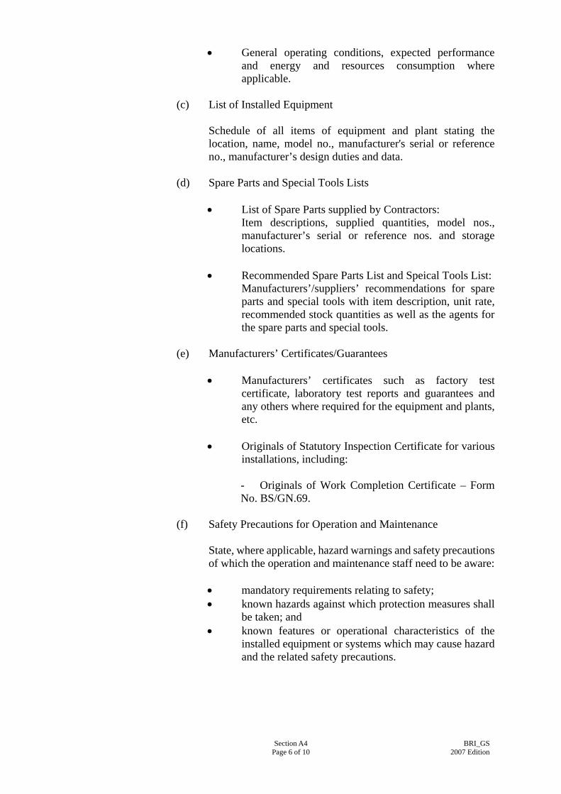
• General operating conditions, expected performance and energy and resources consumption where applicable.
(c) List of Installed Equipment
Schedule of all items of equipment and plant stating the location, name, model no., manufacturer's serial or reference no., manufacturer’s design duties and data.
(d) Spare Parts and Special Tools Lists
• List of Spare Parts supplied by Contractors: Item descriptions, supplied quantities, model nos., manufacturer’s serial or reference nos. and storage locations.
• Recommended Spare Parts List and Speical Tools List:
Manufacturers’/suppliers’ recommendations for spare parts and special tools with item description, unit rate, recommended stock quantities as well as the agents for the spare parts and special tools.
(e) Manufacturers’ Certificates/Guarantees
• Manufacturers’ certificates such as factory test certificate, laboratory test reports and guarantees and any others where required for the equipment and plants, etc.
• Originals of Statutory Inspection Certificate for various
installations, including: - Originals of Work Completion Certificate – Form No. BS/GN.69.
(f) Safety Precautions for Operation and Maintenance
State, where applicable, hazard warnings and safety precautions of which the operation and maintenance staff need to be aware: • mandatory requirements relating to safety; • known hazards against which protection measures shall
be taken; and • known features or operational characteristics of the
installed equipment or systems which may cause hazard and the related safety precautions.
Section A4 Page 6 of 10
BRI_GS2007 Edition

(g) Operation Instructions
Instructions for the safe and efficient operation, under both normal and emergency conditions, of the installed system which shall comprise: • an outline of the operating mode; • control logic and data (sequence, effect, limits of
capability, modes and set points); • procedures and sequences for start-up and shut-down; • interlocks between equipment/system; • calling on of stand-by equipment; • precautions necessary to overcome known hazards; • means by which any potentially hazardous equipment
can be made safe; • estimation of energy consumption and energy costs; • forms for recording plant running hours, energy
consumption and energy costs; and • operating data such as running current, operating
pressure, operating flow rates etc. (h) Maintenance
• Maintenance instructions
Manufacturers’ and the Contractor's recommendations and instructions for the maintenance of the installed equipment. Clear distinction should be made between planned tasks (preventive maintenance) and fault-repair tasks (corrective maintenance). Instructions shall be given on each of the following, as appropriate: - nature of deterioration, and the defects to be looked
for; - isolation and return to service of plant and
equipment; - dismantling and reassembly; - replacement of components and assemblies; - dealing with hazards which may arise during
maintenance; - adjustments, calibration and testing; and - special tools, test equipment and ancillary services.
• Maintenance schedules
Proposed maintenance schedules for all the preventive maintenance tasks identified above. The schedules shall be based on both manufacturers' recommendations and other authoritative sources (e.g. statutory or mandatory requirements) and should include :
Section A4 Page 7 of 10
BRI_GS2007 Edition

- routine servicing; - inspections; - tests and examinations; - adjustments; - calibration; and - overhaul. The frequency of each task may be expressed as specific time intervals, running hours or number of completed operations as appropriate. Collectively, the schedules will form a complete maintenance cycle, repeated throughout the whole working life of the installation.
(i) Drawing Lists
• A complete list of as-built drawings identified with drawing number/reference;
• A complete list of manufacturers’ shop drawings with drawing number/reference, where applicable; and
• A brief description of CD-ROM for these drawings.
(j) Technical Literatures
A complete set of manufacturers' literatures for all the plant and equipment installed in the system. The contents of these literatures shall cover the following areas where applicable: • description of equipment with model numbers
highlighted; • performance - behavioural characteristics of the
equipment; • applications - suitability for use; • factory/laboratory test reports, detailed drawings, circuit
diagrams; • methods of operation and control; • operation instructions; • cleaning and maintenance requirements; • plants, materials and space required for maintenance; • protective measures and safety precautions for operation
and maintenance; and • part lists.
(k) Contact addresses and telephone numbers of suppliers of major equipment.
A4.5.5 Structure and Content of User Manual
The detailed requirements, structure and contents of the User Manual shall include, where applicable, the following information:
Section A4 Page 8 of 10
BRI_GS2007 Edition

(a) Project Information
This shall include: Project title, site address, contract no., contract title, contract commencement date, substantial completion date and end date of Maintenance Period.
(b) System Description
• Type(s) of system(s) and equipment installed, and their purposes;
• Locations of major p lant rooms and riser ducts; • Brief description of the operation and functions of the
systems and equipment; and • Listing of set points which can be adjusted by the user to
suit their operation needs.
(c) Schedule of Major Plant Rooms and Installed Equipment
• Schedule of major plant rooms and riser ducts including their locations; and
• Schedule of major equipment and plants including their locations and serving areas.
(d) Safety Precautions for Operation
Any safety precautions and warnings signals that the users shall be aware of in the daily operation of the various systems and equipment in the installation including: • mandatory requirements relating to safety; • features or operational characteristics of the installed
systems or equipment which may cause hazard and the related safety precautions;
• protective measures and safety precautions for operation; and
• list of warning signals and the related meanings that the user shall be aware of and the actions to be taken.
(e) Operation Instructions
Instructions for the safe and efficient operation, under both normal and emergency conditions, of the installed system which shall comprise: • an outline of the operating mode; • step by step operation instructions for systems and
equipment that are to be operated by the user, including at least procedures for start-up and shut-down;
• means by which any potentially hazardous situation can be made safe; and
Section A4 Page 9 of 10
BRI_GS2007 Edition

• cleaning and basic maintenance procedures.
(f) List of Statutory Periodic Inspections and Tests
A schedule of periodic inspections and tests that owner and/or user of the installation have to arrange to achieve compliance with the requirements stipulated in the relevant Laws of Hong Kong. The frequency of such inspections and tests shall be expressed in specific time intervals.
(g) Drawings A set of selected as-built drawings which shall be able to illustrate to the user the general layout of the completed installation.
(h) Photographs
A set of photographs with suitable captions to illustrate to the user the appearance and locations of devices which require their setting and operation.
A4.5.6 Intellectual Property Rights
The Government shall become the absolute and exclusive owner of the Operation and Maintenance Manuals and the User Manual and all intellectual property rights subsisting therein free from all encumbrances. In the event that the beneficial ownership of any intellectual property rights subsisting in the above Manuals are vested in anyone other than the Contractor, the Contactor shall procure that the beneficial owner shall grant to the Employer a transferable, non-exclusive, royalty-free and irrevocable licence (carrying the right to grant sub-licences) to utilize the intellectual property rights in the manuals for the purposes contemplated in the Contract. For the avoidance of doubt such purposes shall, but not limited to, include providing free copying of the materials in the manuals by any subsequent owner or user of the installation, and/or any party responsible for the operation and maintenance of the installation in connection with any subsequent alteration, extension, operation and maintenance of the installation
Section A4 Page 10 of 10
BRI_GS2007 Edition

PART B - INSTALLATION METHODOLOGY
SECTION B1
BROADCAST RECEPTION (BR) SYSTEM DESIGN
B1.1 GENERAL
A Broadcast Reception system is designed with an aim to convey the best receivable signal at a particular site to individual users sharing the same system. The BR system performance shall comply with EN 50083-7:1996 and EN 50083-10:2002.
B1.2 ONLY ONE BROADCAST RECEPTION SYSTEM PER SITE
Only one Broadcast Reception system shall be installed at a site where a number of blocks are constructed. The Broadcast Reception system shall not radiate interference exceeding the radiation limits as specified in HKTA 1102:2001. The Broadcast Reception system shall have at least 4 number main trunks; one for the broadcasting of the Terrestrial Master Antenna Television System & Satellite Master Antenna Television System and the other main trunks shall be used by other Service Providers. The Broadcast Reception system shall be designed in such a way that all FM/TV/data outlets shall receive signals from all main trunks. One of the typical arrangements is shown in Annex IV.
B1.3 SELECTING THE GAIN OF TV AND FM AERIALS
To maximize signal to noise ratio and to achieve good directivity, the gain of TV and FM aerials shall be chosen to be as high as possible and in compliance with other requirements when specified in the Particular Specification for the installation.
B1.4 SEPARATE DOWN LEADS FOR THE TV AND FM SIGNALS
The TV and FM signals shall be conveyed through separate down leads to the respective amplifiers in the headend circuit for amplification.
Section B1 Page 1 of 2
BRI_GS2007 Edition

B1.5 SELECTION OF AMPLIFIERS
For systems design, which involves the use of amplifiers in the headend to drive the TV channel amplifiers and/or FM channel amplifier, the first amplifiers to be used for the TV and/or FM signal path shall be a TV bandpass preamplifier and/or a FM band preamplifier respectively. Alternatively, a TV bandpass filter shall be used for the TV signal path and shall be connected to the input of the first wideband amplifier, notwithstanding that it is a preamplifier or a distribution amplifier. Such design practice shall ensure that the amplifiers of the system shall not be overloaded by strong out-of-band signals.
B1.6 LOSS ALLOWANCE
A 3 dB attenuation factor shall be included in the calculation of system level to account for practical installation losses such as cable joints.
B1.7 ENCLOSURE OF HEADEND CIRCUIT COMPONENTS
The headend circuit components shall be enclosed in a well-ventilated enclosure fitted with lock. The equipment shall be adequately screened from radio interference caused by lift equipment, starters, etc. The case shall be properly secured against the wall and have sufficient space for cable routing and bending.
B1.8 COMPATIBILITY OF SIGNAL ADAPTORS/SET TOP
BOXES/DIGITAL TERRESTRIAL TELEVISION BASELINE RECEIVERS
The system shall include all equipment and accessories necessary for the successful connection to the signal adaptors/set top boxes/digital terrestrial television baseline receivers provided by service providers.
Section B1 Page 2 of 2
BRI_GS2007 Edition

SECTION B2
SIGNAL LEVEL AT FM/TV/DATA TRIPLEX OUTLET
B2.1 SIGNAL LEVELS The r.m.s. voltage of each carrier at the peak of the modulation envelope when measured at the user’s outlet across a non-inductive 75 ohm resistor (or referred to 75 ohm) shall be:
Minimum Level : 63 dBμV for analogue TV Signal : 55 dBμV for digital TV signal : 50 dBμV for FM signal Maximum Level : 77 dBμV for analogue TV Signal : 72 dBμV for digital TV signal : 70 dBμV for FM signal
B2.2 PERMISSIBLE DIFFERENT SIGNAL LEVELS IN AN OUTLET
The difference in level between the weakest and the strongest TV signals at the same outlet (“tilt”) shall not exceed the followings: Entire range < 12 dB 60 MHz range < 6 dB Adjacent channel < 3 dB
Where adjacent channels are used, the signal level of a distributed digital terrestrial TV broadcast channel shall be at least 5 dB lower than of a wanted adjacent analogue TV channel. If FM sound signals are present at the outlet intended for the TV signals, the level of any FM signal shall be at least 3 dB lower than the lowest TV signal at the outlet. The difference in level between the weakest and the strongest FM signals at the same outlet shall not exceed 15 dB.
B2.3 CARRIER TO NOISE RATIO At any outlet, the level of any unwanted signal generated in the system in any channel shall be: The carrier to noise ratio shall be not less than : 44 dB for analogue TV signal : 34 dB for digital TV signal : 48 dB for FM signals
Section B2 Page 1 of 2
BRI_GS2007 Edition

B2.4 MUTUAL ISOLATION BETWEEN OUTLETS To minimize the local oscillator energy from one receiver causing interference to other receivers on the same cable system, the mutual isolation between outlets connected separately to a spur feeder shall not be less than 36 dB for analogue TV signal, 36 dB for digital TV signal and 42 dB for FM signal.
B2.5 SYSTEM PERFORMANCE WITH RETURN PATH With a QPSK 1,544 Mbits/s injected into any system outlets, the signal received at the Headend shall not be less than: Carrier to noise ratio
≧ 22 dB
Amplitude response variation
≦ 8 dB
Section B2 Page 2 of 2
BRI_GS2007 Edition

SECTION B3
TERRESTRIAL MASTER ANTENNA TELEVISION SYSTEM
B3.1 TERRESTRIAL AERIALS The mast or poles and the aerials shall be of heavy duty construction and be designed to be able to operate normally under a loading pressure associated with a sustained wind speed of up to 170 km/hr. and gusts up to 240 km/hr. The Contractor shall submit detailed builder’s work required within 2 months after the award of the Contract to the Builder prior to commencement of the work. The Contractor shall be responsible for liaison with the Builder to ensure the support structure provided by the Builder is adequate for their aerials installation and also be responsible for checking the positions of the builder’s work on site where reception is at its best before any concrete work is carried out. If the FM aerial is required to be mounted on the same mast for the TV aerial, the two aerials shall be separated by at least 1.8 m apart so as to achieve the minimum interference. The aerial system shall be adequately earthed and protected against lightning in accordance with IEC 62305-1:2006 & relevant current parts by mean of bonding the aerial masts or supporting frames of antenna to the air termination for the lightning protection system with at least 25 mm x 3 mm copper tape or an acceptable equivalent. Separate downleads shall be employed for the TV and FM aerials. The TV and FM signals shall not be combined in front of the channel amplifiers.
B3.2 PREAMPLIFIERS AND FILTERS TV bandpass preamplifiers shall be used in weak TV field strength areas. Similarly, FM band preamplifiers shall be used in weak FM field areas. Alternatively, TV/FM bandpass filters shall be incorporated if wideband preamplifier is used.
B3.3 AMPLIFIERS Signal amplification within the system shall be provided with channel amplifiers at the headend for signal processing and wideband distribution amplifiers. At sites where the aerial is not in direct line-of-sight with the transmitter, the channel amplifier shall be equipped with automatic gain control circuitry.
Section B3 Page 1 of 3
BRI_GS2007 Edition

When channel amplifiers are required, this shall include one channel for FM reception, one channel for closed circuit TV reception, two channel spacings for other paid TV receptions and the numbers of analogue channels & digital channels required for reception of any one free TV programme channel group as required by the location of reception in accordance with the frequency plans allocated for TV and FM receptions, which are announced by OFTA. Only one TV channel group transmitted by any one transmitter location/station shall be relayed. The design levels used for the output of all amplifiers shall be 4 dB lower than their respective maximum allowable output with the exception of channel amplifiers equipped with automatic gain control (AGC) and all amplifiers following these AGC channel amplifiers. The maximum allowable output is the output level at which the specification limit for unwanted signal detailed in the wideband amplifiers, FM channel amplifiers and TV channel amplifiers & AGC channel amplifiers etc. can no longer be met with further increase in outputs. A lockable well-ventilated metal enclosure shall be installed to house all headend circuit components. The case shall be properly secured against the wall and have sufficient space for cable routing and bending. The headend equipment of each system shall be installed in the Telecommunication & Broadcasting Equipment (TBE) Room or in the location of Headend Equipment Room as shown on the Drawings. Cable routing shall be as short as possible from antennae to the channel amplifiers/modulator.
B3.4 FREQUENCY CONVERTERS Television signals shall be conveyed at the received signal frequencies. If frequency conversion is required, the outlet frequencies shall be in the frequencies 470 to 862 MHz for television reception.
B3.5 UHF MODULATORS If closed circuit television system camera signals are to be included in the BR system, the video signals shall be modulated to UHF range channels and combined at the headend of the system.
B3.6 SPLITTERS/TEE-UNITS All splitters and tee units shall have a wide bandwidth to allow for cascaded mode of operation. The maximum number of tee units in cascade shall be limited to 6. Mock-up tests may be required to assess the design prior to installation, if in the opinion of the Architect, the cascaded chain is too long as to create unacceptable signal strength.
Section B3 Page 2 of 3
BRI_GS2007 Edition

B3.7 COAXIAL CABLES Co-axial cable shall not be bent to a radius smaller than 15 times the outer diameter of the cable. Joints in the cable runs and looping of cables at outlet terminals shall NOT be allowed. All wiring shall be properly installed and segregated in accordance with the latest edition of the “Code of Practice for the Electricity (Wiring) Regulations” issued by the Electrical & Mechanical Services Department and the “General Specification for Electrical Installation”. The Contractor shall install the equipment, cabling, etc. in location as indicated on the drawings accompanied with the specification. All cables and wiring shall be run and terminated inside concealed conduits/trunkings and IEC 60670-1:2002 box, etc.
B3.8 FM/TV/DATA TRIPLEX OUTLETS Looping of outlets to achieve the sufficient isolation shall NOT be acceptable. Only isolation using splitters and tee units with isolation shall be considered.
B3.9 FIBRE OPTICAL CABLE SYSTEM
Fibre optical cable system should be provided where the length of main trunk cable without joint exceeds 200 meters. The fibre optical cable in riser shall be enclosed in a galvanized iron cable trunking with space factor not exceeding 40%. In any case, the cable trunking should not be smaller than 50 mm x 50 mm. Where the main trunk is installed underground, the fibre optical cables shall be protected by minimum 100 dia. galvanized iron pipes and cable draw pits. Fibre optical cable amplifier shall be provided where the total attenuation loss of the optical circuit exceeds the maximum output power of the transmitter. The length of fibre optical cables without joint between the optical transmitter and the fibre optical splitter shall not exceed 5000 meters and between the fibre optical splitter and the fibre optical transceiver exceeds 2000 meters.
Section B3 Page 3 of 3
BRI_GS2007 Edition
SECTION B4
SATELLITE MASTER ANTENNA TELEVISION SYSTEM
B4.1 SMATV SYSTEM INSTALLER REQUIREMENTS The Contractor shall be a Licence holder or employ the Licence holder on the List of SMATV Licence Holders registered by the OFTA to carry out the SMATV system installation. The Contractor shall make application to the OFTA for the installation works.
B4.2 THE SMATV SYSTEM REQUIREMENTS
B4.2.1 Antenna Location
The SMATV System shall be installed in the location such that (a) It has a clear, unobstructed view of the target satellite; (b) It has no condensation in its vicinity; and (c) It is at least 3 meters clear of fences or enclosure.
B4.2.2 Support for the Dish Antenna The steel framework and mounting of the dish antenna shall be capable to withstand the loading pressure associated with sustained wind speed up to 170 km/hr. and gusts up to 240 km/hr. without any physical damage. The Contractor shall be responsible for liaison with the Builder to ensure the support structure provided by the Builder is adequate for their antenna installation and also be responsible for checking the positions of the builder’s work on site where reception is at its best before any concrete work is carried out.
B4.2.3 Antenna Installation The antenna shall be of heavy duty construction and be designed to be able to operate normally under a loading pressure associated with a sustained wind speed of up to 170 km/hr. and gusts up to 240 km/hr and shall be installed in such a way that it shall not warp. The antenna shall be smooth, not rough or bumpy. The antenna shall not twist or rock under stress. Rubber grommets shall be inserted between the steel supports and the aluminum dish antenna to prevent electrolysis action.
Section B4 Page 1 of 2
BRI_GS2007 Edition

Both the antenna and its supports shall be adequately earthed and protected against lightning in accordance with IEC 62305-1:2006 & relevant current parts by mean of bonding the antenna and its supporting frames to the air termination of the lightning protection system with at least 25 mm x 3 mm copper tape or product having equivalent functions or performance. The Contractor shall carry out the earth bonding. The antenna and its supporting structure shall be provided with a durable protective coating.
B4.3 FEEDHORN/LOW NOISE AMPLIFIER (LNA)/LOW NOISE BLOCK
DOWN CONVERTER (LNB) The feedhorn shall be strictly installed in accordance with manufacturer’s recommendation. The Contractor shall submit the manufacturer’s recommended installation method to the Architect for approval within 2 months after award of the Contract. The feedhorn shall be positioned in the focus point of the satellite TV antenna and adequately supported. Gaskets recommended by the manufacturer shall be used between the feedhorn and the LNA/LNB to avoid leakage of signal. The sealant between the gaskets shall be in accordance with the manufacturer’s recommendation to ensure that the waveguide is in good metal-to-metal contact.
B4.4 SATELLITE RECEIVERS AND MODULATORS
The satellite receivers and modulators shall be earthed in accordance with the “General Specification for Electrical Installation in Government Buildings, Hong Kong, issued by Architectural Services Department, the Government of the HKSAR”.
Section B4 Page 2 of 2
BRI_GS2007 Edition
Section B5 Page 1 of 1
BRI_GS2007 Edition
SECTION B5
ANCILLARY SYSTEM
B5.1 CONDUITS & CABLE TRUNKINGS The Contractor shall install the equipment, cabling, etc in location as indicated on the drawings accompanied with the specification. All cables and wiring shall be run and terminated inside conduits/trunkings and 47 mm deep IEC 60670-1:2002 box, etc. The Contractor shall supply and install 25 mm dia. steel conduit terminating at the headend equipment cabinet in the headend equipment room to enclose the down leads all the way from the antenna.
B5.2 POWER SUPPLY Power supply for the amplifier/receivers shall be taken from the 13A fused spur units c/w pilot light at positions as shown on the Drawings. The Contractor shall be responsible for all the wiring from this location to the power supply unit, amplifier, etc. If additional 13A fused spur units c/w pilot light are required, the Contractor shall be responsible for the supply and installation. The Contractor shall also supply and install the automatic voltage regulators and/or uninterruptible power supply, where required, for proper functioning of the whole Broadcast Reception system.

PART C - MATERIAL AND EQUIPMENT SPECIFICATION
SECTION C1
GENERAL
C1.1 GENERAL REQUIREMENT
All apparatus, equipment, materials and wiring shall be suitable for use on 220 V + 6 %, 50 Hz + 2 Hz , single phase a.c. system at the following Services Conditions:
(a) Climate: Hong Kong (tropical); (b) Ambient temperature: Peak -5°C to +40°C (continuously 4 hours) Average 0°C to +35°C (over 24 hours); (c) Altitude: up to 2000 m above sea level; and (d) Relative humidity: 98% maximum
It should be noted that the supply voltage may be interrupted such that its frequency or voltage value may fluctuate outside the above acceptable range. It is advisable that the equipment should be able to ride through or function properly due to any unavoidable disturbance illustrated in the European Standard EN 50160:1999 and if not, the Contractor should state the performance of the equipment being compiled with the specification requirements.
The Contractor should also make reference to the international practices of voltage dip ride-through capability, such as Semiconductor Equipment and Materials International (SEMI) F47 and IEC 61000-4-11:2004 & IEC 61000-4-34:2005.
Section C1 Page 1of 1
BRI_GS2007 Edition

SECTION C2
TERRESTRIAL MASTER ANTENNA TELEVISION SYSTEM
C2.1 TERRESTRIAL AERIALS The terrestrial aerials shall be suitable for both analogue and digital terrestrial television and shall comply the following: (a) TV aerial should have a gain of at least 13 dB and a front to back ratio of at least 28 dB. The aerial shall be of the type to minimize ghost image; (b) FM aerial should have a gain of at least 6 dB; (c) The impedance of the aerial should be 75 ohm unbalanced; (d) The aerial system should be provided with a durable protective coating; (e) The aerial mast should be made of stainless steel; and (f) The aerial should be capable of receiving analogue and digital signals.
C2.2 PREAMPLIFIERS AND FILTERS
The performance of the preamplifiers, TV bandpass preamplifiers, FM bandpass preamplifiers, TV bandpass filters and FM bandpass filters shall be suitable for both analogue and digital terrestrial television and shall comply with the following: C2.2.1 Preamplifiers
Television Standard PAL I System
Frequency
FM : 88 to 108 MHz TV : 54 to 862 MHz
Gain ≧ 20 dB
Input Split input configuration
Output Level ≧ 90 dBμV
Noise Figure
< 5.5 dB
Impedance (Input & Output)
75 ohms
Housing Weatherproof housing suitable for outdoor
mounting
Section C2 Page 1 of 12
BRI_GS2007 Edition
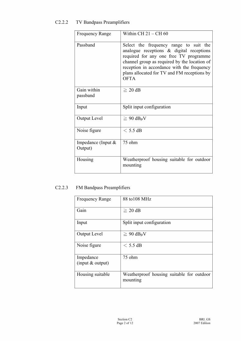
C2.2.2 TV Bandpass Preamplifiers Frequency Range Within CH 21 – CH 60
Passband Select the frequency range to suit the
analogue receptions & digital receptions required for any one free TV programme channel group as required by the location of reception in accordance with the frequency plans allocated for TV and FM receptions by OFTA
Gain within passband
≧ 20 dB
Input Split input configuration
Output Level ≧ 90 dBμV
Noise figure < 5.5 dB
Impedance (Input & Output)
75 ohm
Housing Weatherproof housing suitable for outdoor mounting
C2.2.3 FM Bandpass Preamplifiers
Frequency Range 88 to108 MHz
Gain ≧ 20 dB
Input Split input configuration
Output Level
≧ 90 dBμV
Noise figure < 5.5 dB
Impedance (input & output)
75 ohm
Housing suitable Weatherproof housing suitable for outdoor mounting
Section C2 Page 2 of 12
BRI_GS2007 Edition

C2.2.4 TV Bandpass Filters Frequency Range
Within CH 21 – CH 60
Passband
Select the frequency range to suit the analogue receptions & digital receptions required for any one free TV programme channel group as required by the location of reception in accordance with the frequency plans allocated for TV and FM receptions by OFTA
Loss within passband
Not more than 5.0 dB
Impedance (Input & Output)
75 ohm
C2.2.5 FM Bandpass Filters
Frequency Range
88 to108 MHz
Loss within passband
Not more than 5.0 dB
Impedance (input & output)
75 ohm
C2.3 AMPLIFIERS
The performances of the wideband amplifiers, FM channel amplifiers and TV channel amplifiers with AGC modules shall be suitable for both analogue and digital terrestrial television and shall comply and the following:
Section C2 Page 3 of 12
BRI_GS2007 Edition

C2.3.1 Wideband Amplifiers Television Standard PAL I System
Frequency Range & 54 to 862 MHz Passive Return Path
5 to 42 MHz
Gain & Return Path Gain
≧ 25 dB & ≧ 10 dB
Output Level & Return Path Output Level
≧ 100 dBμV & ≧ 90 dBμV
Noise Figure < 8.5 dB
Nominal Impedance (Input & Output)
75 ohms
Return Loss (Input & Output)
≧ 10 dB
Housing Either internally or externally fully screened
metal box complete with suitable mounting legs for vertical mounting
Earthing All metal parts to be properly earthed
Identification Clearly mark ‘IN’ & ‘OUT’ signal sockets
Accessories All necessary coaxial cable plug and accessories
Section C2 Page 4 of 12
BRI_GS2007 Edition

C2.3.2 FM Channel Amplifiers with Processor Frequency Band FM
Input Frequency Range
88 to 108 MHz
Gain
≧ 20 dB
Automatic Gain Control Range
≧ 20 dB
Noise Figure Less than 7 dB
Input Level Between 40 - 80 dBμV
Output Level ≧ 70 dBμV
Output Frequency Range
Convert to the frequency range within 88 to 108 MHz
Impedance (Input & Output)
75 ohms
Return Loss (Input & Output)
≧ 10 dB
Weather proofing Indoor application
Housing Modular type construction of robust and
attractively designed plug-in units with connecting links between TV channel amplifier outputs. Fully internally metal-screened. Earthing on metal chasis.
Identification Clearly marked ‘IN’ & ‘OUT’ signal sockets
Section C2 Page 5 of 12
BRI_GS2007 Edition
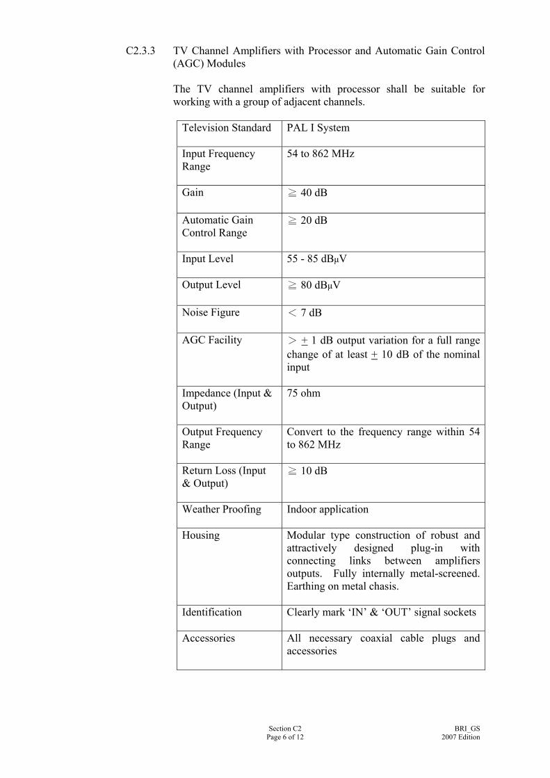
C2.3.3 TV Channel Amplifiers with Processor and Automatic Gain Control (AGC) Modules
The TV channel amplifiers with processor shall be suitable for working with a group of adjacent channels.
Television Standard PAL I System
Input Frequency Range
54 to 862 MHz
Gain ≧ 40 dB
Automatic Gain Control Range
≧ 20 dB
Input Level 55 - 85 dBμV
Output Level ≧ 80 dBμV
Noise Figure < 7 dB
AGC Facility > + 1 dB output variation for a full range
change of at least + 10 dB of the nominal input
Impedance (Input & Output)
75 ohm
Output Frequency Range
Convert to the frequency range within 54 to 862 MHz
Return Loss (Input & Output)
≧ 10 dB
Weather Proofing Indoor application
Housing Modular type construction of robust and
attractively designed plug-in with connecting links between amplifiers outputs. Fully internally metal-screened. Earthing on metal chasis.
Identification Clearly mark ‘IN’ & ‘OUT’ signal sockets
Accessories All necessary coaxial cable plugs and accessories
Section C2 Page 6 of 12
BRI_GS2007 Edition
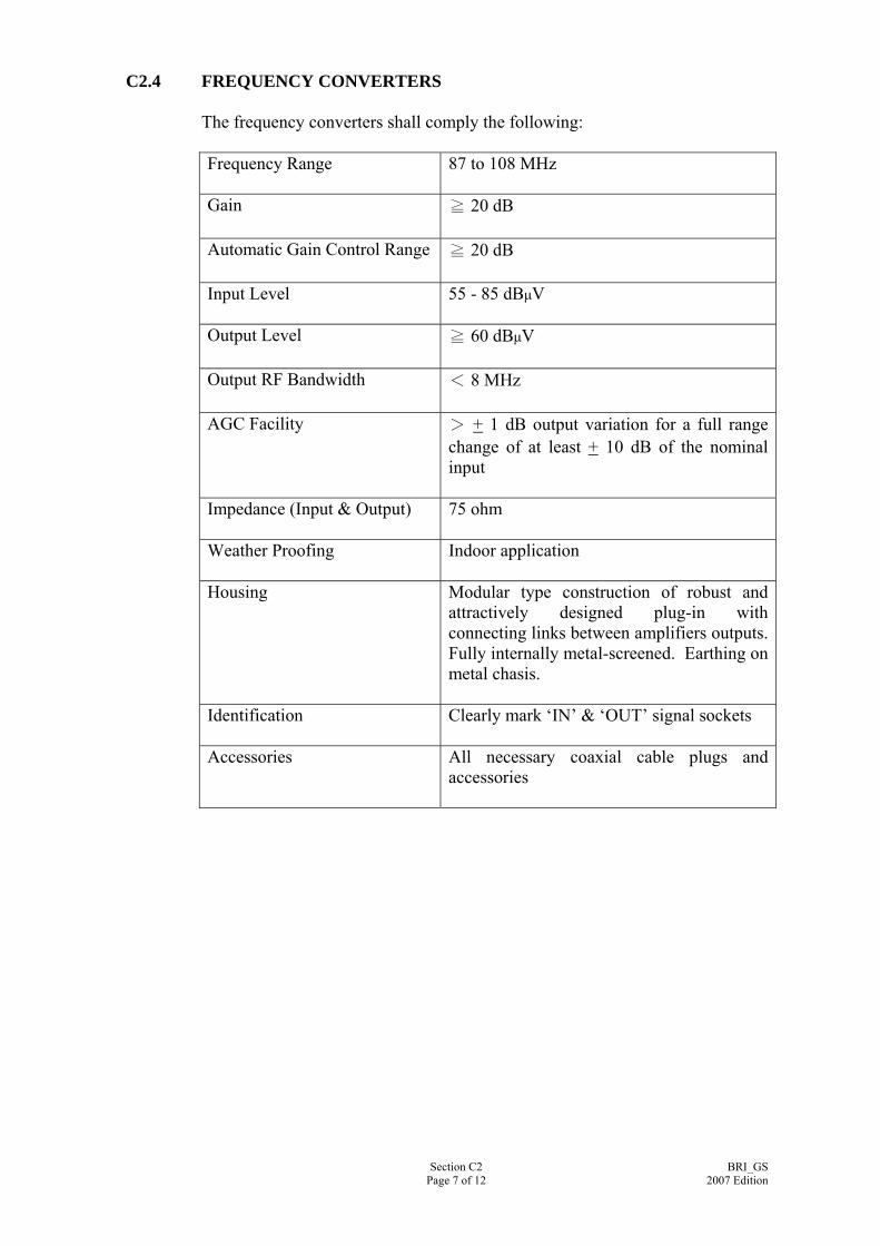
C2.4 FREQUENCY CONVERTERS The frequency converters shall comply the following:
Frequency Range 87 to 108 MHz
Gain ≧ 20 dB
Automatic Gain Control Range ≧ 20 dB
Input Level 55 - 85 dBμV
Output Level ≧ 60 dBμV
Output RF Bandwidth < 8 MHz
AGC Facility > + 1 dB output variation for a full range
change of at least + 10 dB of the nominal input
Impedance (Input & Output)
75 ohm
Weather Proofing Indoor application
Housing Modular type construction of robust and attractively designed plug-in with connecting links between amplifiers outputs. Fully internally metal-screened. Earthing on metal chasis.
Identification Clearly mark ‘IN’ & ‘OUT’ signal sockets
Accessories All necessary coaxial cable plugs and accessories
Section C2 Page 7 of 12
BRI_GS2007 Edition

C2.5 UHF MODULATORS The UHF modulators shall comply the following: Video Input Level 1 + 0.3 Vpp
Video Input Impedance 75 ohm
Video Bandwidth 0.020 – 5.0 MHz
Output Frequency Range 54 to 862 MHz
fixed channel or channel selectable
Output Impedance
75 ohm
Output RF Bandwidth < 8 MHz
Output Level (without integrated channel amp) (with integrated channel amp)
> 80 dBμV > 110 dBμV
C2.6 SPLITTERS/TEE-UNITS
All splitters and tee units shall have a wide bandwidth to allow for cascaded mode of operation, shall have return path and shall comply the following: C2.6.1 Splitters
Frequency Range 5 to 862 MHz
Distribution Loss ≦ 8 dB
Mutual Attenuation between Outputs
Not less than 13 dB for splitters at all in-band frequencies
Impedance 75 ohm
Return Loss (Input & Output)
≧ 14 dB
Section C2 Page 8 of 12
BRI_GS2007 Edition

C.2.6.2 Tee Units
Frequency Range 5 to 862 MHz
Thru Loss ≦ 6 dB
Side Loss ≦ 16.5 dB
Mutual Attenuation between Outputs
Not less than 28 dB for tee units at all in-band frequencies
Impedance 75 ohm
Return Loss (Input & Output)
≧ 18 dB
C2.7 COAXIAL CABLES
All coaxial cables used shall be of 75 ohm type copper cables designed for transmitting 5 to 2150 MHz signals and shall have thermosetting insulated, with low emission of smoke and corrosive gases when affected by fire. The fire performance of the insulated material with low emission of smoke and corrosive gases when affected by fire shall complies with the following requirements: (i) Flame propagation : IEC 60332-1-1:2004; (ii) Smoke emission : IEC 61034-2:2005; and (iii) Acid gas emission : IEC 60754-1:1994 The coaxial cables for feeder shall conform to cable designation 8 or above of IEC 60096-3:1982 and the coaxial cables for trunk feeder shall be to cable designation 6 or above of IEC 60096-3:1982. Underground coaxial cables shall be with polyethylene outer sheath, copper foil outer conductor, and PVC insulation. The cable shall be to cable designation 6 or above of IEC 60096-3:1982. All coaxial cables shall have distinctive labels/brand name along its length.
Section C2 Page 9 of 12
BRI_GS2007 Edition
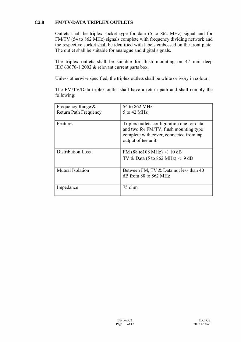
C2.8 FM/TV/DATA TRIPLEX OUTLETS Outlets shall be triplex socket type for data (5 to 862 MHz) signal and for FM/TV (54 to 862 MHz) signals complete with frequency dividing network and the respective socket shall be identified with labels embossed on the front plate. The outlet shall be suitable for analogue and digital signals. The triplex outlets shall be suitable for flush mounting on 47 mm deep IEC 60670-1:2002 & relevant current parts box. Unless otherwise specified, the triplex outlets shall be white or ivory in colour. The FM/TV/Data triplex outlet shall have a return path and shall comply the following: Frequency Range & Return Path Frequency
54 to 862 MHz 5 to 42 MHz
Features Triplex outlets configuration one for data
and two for FM/TV, flush mounting type complete with cover, connected from tap output of tee unit.
Distribution Loss FM (88 to108 MHz) < 10 dB TV & Data (5 to 862 MHz) < 9 dB
Mutual Isolation Between FM, TV & Data not less than 40 dB from 88 to 862 MHz
Impedance 75 ohm
Section C2 Page 10 of 12
BRI_GS2007 Edition

C2.9 FIBER OPTICAL TRANSMITTER The fiber optical transmitter shall be of modular design and shall comply the following: Frequency 54 to 862 MHz
Input Impedance 75 ohm
Optical Wavelength 1310 nm ± 10 nm
Optical Output Power ≧ 6 dBm
Optical Return Loss ≧ 55 dB
RF Input Level per Channel ≧ 60 dBμV
Number of TV channels 42
Light Source – LED
Laser Diode
< 2 km < 40 km
The fiber optical return path transmitter shall be of modular design and shall comply the following:
Return Path Frequency 5 to 42 MHz
Input Impedance 75 ohm
Optical Wavelength 1310 nm ± 10 nm
Optical Output Power
≧ 6 dBm
Optical Return Loss ≧ 55 dB
RF Input Level per Channel
≧ 60 dBμV
Light Source – LED Laser Diode
< 2 km < 40 km
Section C2 Page 11 of 12
BRI_GS2007 Edition
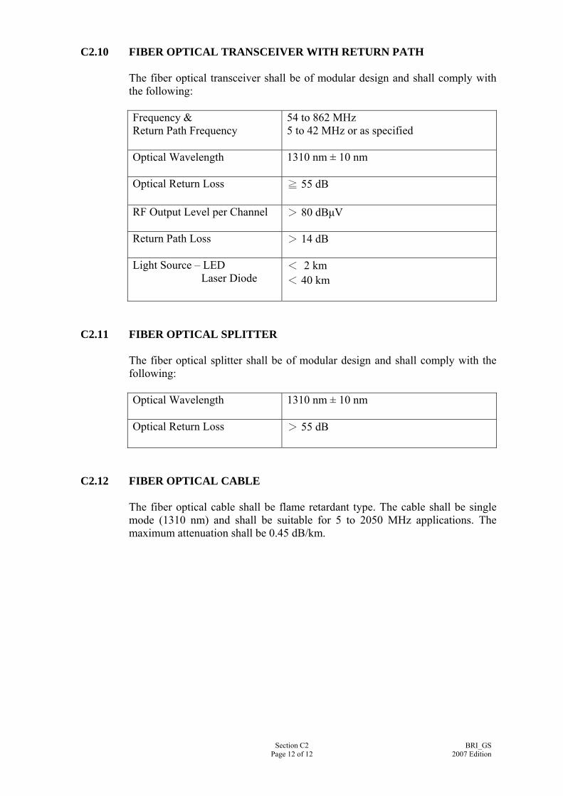
C2.10 FIBER OPTICAL TRANSCEIVER WITH RETURN PATH The fiber optical transceiver shall be of modular design and shall comply with the following: Frequency & Return Path Frequency
54 to 862 MHz 5 to 42 MHz or as specified
Optical Wavelength 1310 nm ± 10 nm
Optical Return Loss ≧ 55 dB
RF Output Level per Channel
> 80 dBμV
Return Path Loss
> 14 dB
Light Source – LED Laser Diode
< 2 km < 40 km
C2.11 FIBER OPTICAL SPLITTER
The fiber optical splitter shall be of modular design and shall comply with the following: Optical Wavelength 1310 nm ± 10 nm
Optical Return Loss > 55 dB
C2.12 FIBER OPTICAL CABLE
The fiber optical cable shall be flame retardant type. The cable shall be single mode (1310 nm) and shall be suitable for 5 to 2050 MHz applications. The maximum attenuation shall be 0.45 dB/km.
Section C2 Page 12 of 12
BRI_GS2007 Edition
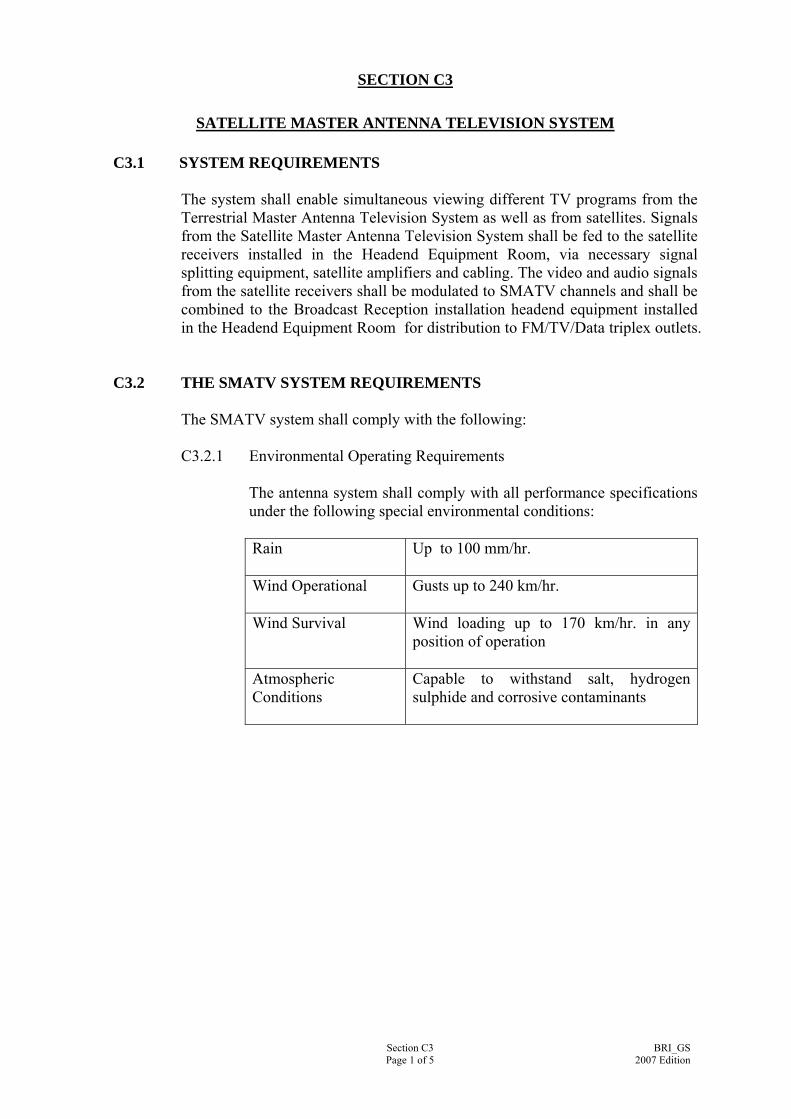
SECTION C3
SATELLITE MASTER ANTENNA TELEVISION SYSTEM C3.1 SYSTEM REQUIREMENTS
The system shall enable simultaneous viewing different TV programs from the Terrestrial Master Antenna Television System as well as from satellites. Signals from the Satellite Master Antenna Television System shall be fed to the satellite receivers installed in the Headend Equipment Room, via necessary signal splitting equipment, satellite amplifiers and cabling. The video and audio signals from the satellite receivers shall be modulated to SMATV channels and shall be combined to the Broadcast Reception installation headend equipment installed in the Headend Equipment Room for distribution to FM/TV/Data triplex outlets.
C3.2 THE SMATV SYSTEM REQUIREMENTS
The SMATV system shall comply with the following: C3.2.1 Environmental Operating Requirements
The antenna system shall comply with all performance specifications under the following special environmental conditions: Rain Up to 100 mm/hr.
Wind Operational Gusts up to 240 km/hr.
Wind Survival Wind loading up to 170 km/hr. in any
position of operation
Atmospheric Conditions
Capable to withstand salt, hydrogen sulphide and corrosive contaminants
Section C3 Page 1 of 5
BRI_GS2007 Edition
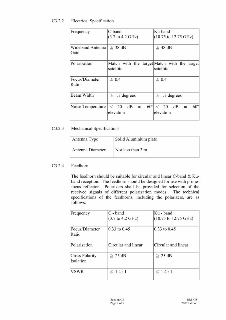
C3.2.2 Electrical Specification Frequency C-band
(3.7 to 4.2 GHz)
Ku-band (10.75 to 12.75 GHz)
Wideband Antenna Gain
≧ 38 dB ≧ 48 dB
Polarisation Match with the target satellite
Match with the target satellite
Focus/Diameter Ratio
≦ 0.4 ≦ 0.4
Beam Width ≦ 1.7 degrees ≦ 1.7 degrees
Noise Temperature < 20 dB at 60o
elevation < 20 dB at 60o
elevation
C3.2.3 Mechanical Specifications
Antenna Type Solid Aluminium plate
Antenna Diameter Not less than 3 m
C3.2.4 Feedhorn The feedhorn should be suitable for circular and linear C-band & Ku-band reception. The feedhorn should be designed for use with prime-focus reflector. Polarizers shall be provided for selection of the received signals of different polarization modes. The technical specifications of the feedhorns, including the polarizers, are as follows: Frequency C - band
(3.7 to 4.2 GHz)
Ku - band (10.75 to 12.75 GHz)
Focus/Diameter Ratio
0.33 to 0.45 0.33 to 0.45
Polarization Circular and linear Circular and linear
Cross Polarity Isolation
≧ 25 dB ≧ 25 dB
VSWR ≦ 1.4 : 1 ≦ 1.4 : 1
Section C3 Page 2 of 5
BRI_GS2007 Edition

C3.2.5 Low Noise Amplifier (LNA) /Low Noise Block Down Converter (LNB) Input Frequency C - band
(3.7 to 4.2 GHz)
Ku - band (10.75 to 12.75 GHz)
Minimum Input Level
≦ -100 dBm ≦ -100 dBm
Gain
≧ 55 dB ≧ 55 dB
Input VSWR ≦ 2.5 : 1 ≦ 2.5 : 1
Image Rejection Ratio
≧ 40 dB ≧ 40 dB
Output Frequency 950 - 2050 MHz 950 - 2050 MHz
Output VSWR ≦ 1.5 : 1 ≦ 1.5 : 1
C3.3 SATELLITE RECEIVERS
The satellite receivers shall be multi-system compatible and shall comply the following: C3.3.1 RF Signal
Input frequency 950 – 2050 MHz
Input signal level - 60 dBm to – 30 dBm
IF bandwidth 18 MHz, 27 MHz
FM threshold 8 dB C/N
C3.3.2 Video Parameters
Video de-emphasis ITU-R 405 -1 525, 625 lines
Video frequency response + 3 dB at 20 Hz to 5 MHz
Video output level 1 Volt peak-to-peak, 75 ohm
Baseband de-emphasis Flat
Section C3 Page 3 of 5
BRI_GS2007 Edition

C3.3.3 Audio Parameters
Audio subcarrier tuning 4.5 to 8.8 MHz
Audio response 20 Hz to 20 kHz, + 0.5 dB
Audio de-emphasis 50 μs, J17
Audio distortion less than 2 % THD
C3.4 SATELLITE AMPLIFIER
The satellite amplifier shall be suitable for the SMATV application. The technical specification of the amplifiers receivers are as follows: Input frequency 950 – 2050 MHz
Gain ≧ 20
Output level at 35dB CMR ≧ 110 dB
Noise figure ≦ 6 dB
Impedance (Input & Output) 75 ohm
Return Loss (Input & Output) ≧ 10 dB
C3.5 SPLITTER/TEE-UNIT All splitter and tee unit shall have a wide bandwidth to allow for cascaded mode of operation and shall comply with the following: C.3.5.1 Splitters
Frequency Range 950 to 2050 MHz
Distribution Loss ≦ 11 dB
Mutual Attenuation between Outputs
> 13 dB for splitters at all in-band frequencies
Impedance 75 ohm
Return Loss (Input & Output)
≧ 10 dB
Section C3 Page 4 of 5
BRI_GS2007 Edition
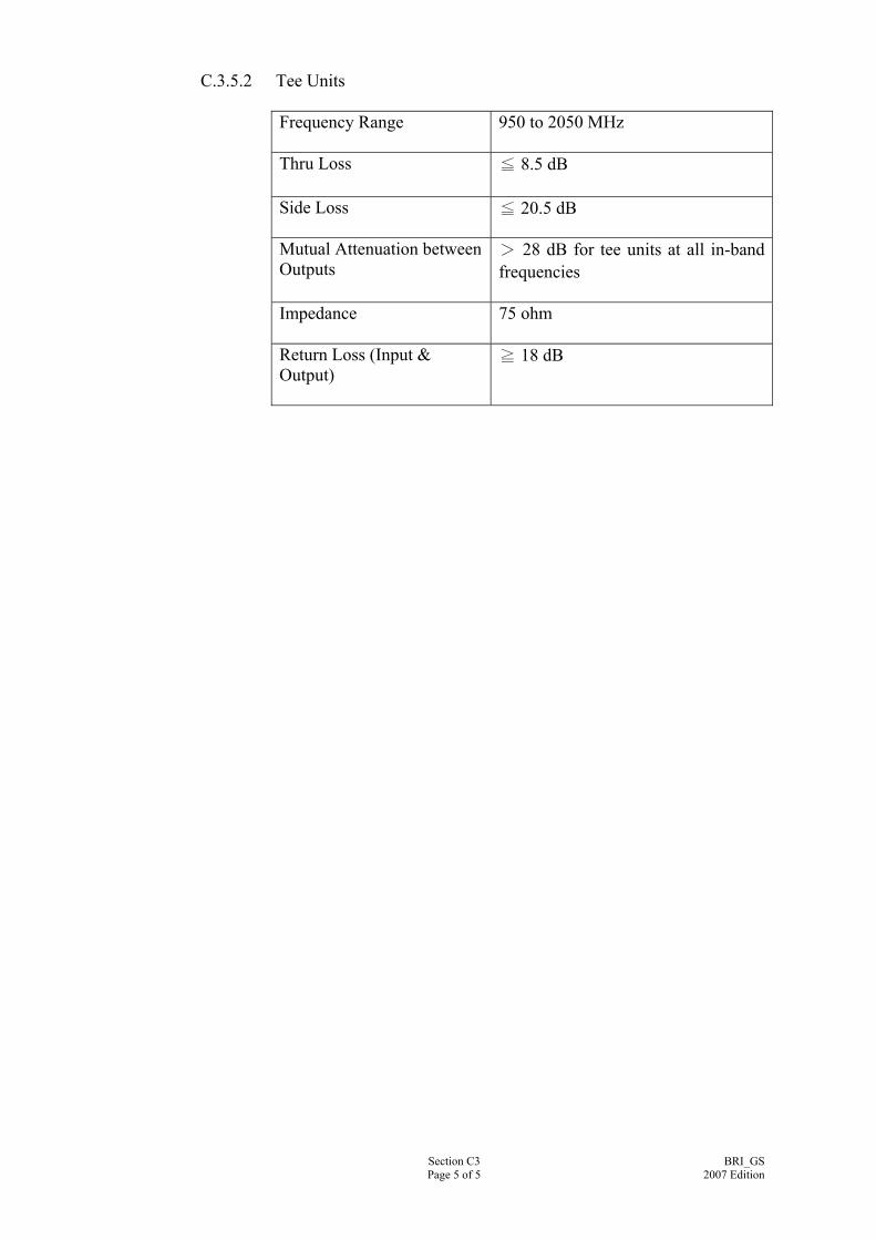
C.3.5.2 Tee Units
Frequency Range 950 to 2050 MHz
Thru Loss ≦ 8.5 dB
Side Loss
≦ 20.5 dB
Mutual Attenuation between Outputs
> 28 dB for tee units at all in-band frequencies
Impedance 75 ohm
Return Loss (Input & Output)
≧ 18 dB
Section C3 Page 5 of 5
BRI_GS2007 Edition
SECTION C4
ANCILLARY SYSTEM
C4.1 CABLE TRUNKING Cable trunking shall be in accordance with the “General Specification for Electrical Installation in Government Buildings, Hong Kong, issued by Architectural Services Department, the Government of the HKSAR”.
C4.2 CONDUIT AND ACCESSORIES Conduit & accessories shall be in accordance with the “General Specification for Electrical Installation in Government Buildings, Hong Kong, issued by Architectural Services Department, the Government of the HKSAR”.
C4.3 POWER CABLE Power cable shall be in accordance with the “General Specification for Electrical Installation in Government Buildings, Hong Kong, issued by Architectural Services Department, the Government of the HKSAR”.
Section C4 Page 1 of 1
BRI_GS2007 Edition

PART D - INSPECTION, TESTING AND COMMISSIONING DURING CONSTRUCTION PERIOD
SECTION D1
GENERAL REQUIREMENT
D1.1 GENERAL REQUIREMENT The purpose of Inspection, Testing and Commissioning during construction is to ensure the quality of delivered material and equipment and the workmanship of the installation comply with the relevant Regulations, Standards, Code of Practice and requirements of the Contract and the function and performance of the systems meet the requirements specified in the Contract. Inspection and testing shall be carried out on all new installations and alterations to an existing installation in accordance with the requirements of this Section. At the start of the Contract, the Contract shall propose and obtain agreements from the Architect on the time frames for the process of verification of materials and equipment delivered on site, inspection and testing of installed works. The Contractor shall be responsible to submit relevant documents including testing and commissioning procedures and the testing and commissioning progress chart in the “Testing and Commissioning Procedure for Broadcast Reception Installation in Government Buildings, Hong Kong Special Administrative Region”, to the Architect about the materials, equipment and installations to be inspected, tested and commissioned before carrying out of the inspection, tests and commissioning. The Contractor shall provide all necessary specialists, labour, materials, tools, instruments and equipment and consumables for carrying out of inspections, testing including analyzing the data, and commissioning. The entire testing and commissioning procedures shall be undertaken by the Contractor’s own competent specialist or by a competent independent Commissioning Specialist nominated by and acting for the Contractor and approved by the Architect. The Contractor shall dispatch competent and experienced commissioning engineers to carry out the test and commissioning of the installation. Such personnel shall collaborate closely with the Architect’s Representative on site, who will witness the tests carried out under the Contract. The Contractor shall provide the Architect’s Representative with access to inspect all equipment during any phase of the installation and shall provide all reasonable facilities for such access. The Contractor shall notify the Architect of impending tests in good time (usually not less than 3 working days) to allow the Architect or the Architect’s Representative to be present and the Contractor shall provide details of date, time and type of tests to be performed. Parts to be subjected to witnessed tests will not be accepted unless the relevant test results are provided and have been signed by the Architect’s Representative and Contractor.
Section D1 Page 1 of 2
BRI_GS2007 Edition

All tests at site shall be performed in the sequence required by the construction and commissioning programme. The Contractor shall prepare itemised and detailed testing and commissioning schedule. The schedule shall be completed by the Contractor and signed by the Architect’s Representative during the tests and, after signature, shall be collated and presented to the Architect for approval. The Contractor shall also supply calibrated instrument as detailed in Annex III. The instrument shall be calibrated by laboratories accredited by the Hong Kong Laboratory Accreditation Scheme (HOKLAS) or other recognized accredited laboratories. The calibration shall be made against certified equipment having a known valid relationship to internationally or nationally recognized standards. Where no such standards exist, the basis used for calibration shall be documented. In such cases, the laboratories shall provide satisfactory evidence of correlation of results, for example by participation in a suitable programme of inter – laboratory comparisons or proficiency testing. The entire installation shall be commissioned and tested in accordance with the latest edition of “Testing and Commissioning Procedure for Broadcast Reception Installation in Government Buildings, Hong Kong Special Administrative Region”. The Contractor shall record all data and information gathered during all inspections, testing and commissioning and produce reports to the Architect within 3 weeks after the inspection, testing and commissioning records shall bear the names and signature of the representatives of the Architect and maintenance agent, who witness the inspections, testing and commissioning. Upon completion of such T & C procedure, the Contractor shall complete and sign a testing and commissioning certificate as shown in the “Testing and Commissioning Procedure for Broadcast Reception Installation in Government Buildings, Hong Kong Special Administrative Region”. The Contractor at their own expense shall rectify all defects in performance, material and workmanship before the installation is accepted.
Section D1 Page 2 of 2
BRI_GS2007 Edition
SECTION D2
ROUTINE INSPECTION
D2.1 INSPECTION OF MATERIALS AND EQUIPMENT DELIVERED TO SITE
Before any materials and equipment delivered to site, the Contractor shall give due advanced notice of not less than three days and provide details of date, time and list of items to be inspected to the Architect or his representative for approval. The request for inspection shall be made together with detail descriptions of the materials/equipment including, but not limited to, brand name, model number, country of origin, their tested standards and record of Architect’s approval for the using the materials and equipment.
D2.2 VISUAL INSPECTION OF INSTALLATION
A visual inspection shall be carried out before testing of the installation in order to verify the following: (a) The installation has been carried out in compliance with the specified
requirements; (b) The correctness of the designation of the installation; and (c) There is no visual damage to the installation.
D2.3 INSPECTION AND FUNCTIONAL TEST OF INSTALLED WORKS
Where tests are required to be witnessed by the Architect or his representative and site supervisory staff, the Contractor shall give due advanced notice of not less than three days and provide details of date, time and lists of works to be inspected and tested. The Contractor shall carry out the tests and inspections as shown in the following sections and record the test results and as agreed between the Architect or his representative and the Contractor. Registered or suitably qualified electrical workers shall be employed to conduct such tests.
Section D3 Page 1 of 1
BRI_GS2007 Edition

SECTION D3
HANDOVER INSPECTION
Before handover of any materials and equipment to the Architect or his representative, the Contractor shall give due advanced notice of not less than three days and provide details of date, time and list of items to be tested and commissioned to the Architect or his representative for approval. The Contractor shall follow the details of the testing and commissioning procedures as shown in Section D4.
Section D3 Page 1 of 1
BRI_GS2007 Edition

SECTION D4
TESTING AND COMMISSIONING
D4.1 GENERAL
Upon completion of the installed works, the Contractor shall give due advanced notice and provide details of date, time and list of testing and commissioning works to the Architect or his representative for approval. The Contractor shall submit the appropriate schedule and phasing of the testing and commissioning works as agreed by the Architect or his representative. Where testing and commissioning works are required to be witnessed by the Architect or his representative and site supervisory staff, the Contractor shall carry out the proper testing and commissioning works before inviting them to witness the works.
D4.2 TESTING AND COMMISSIONING PROCEDURES
The Contractor shall carry out the testing and commissioning works in accordance with the Testing and Commissioning Procedure for Broadcast Reception Installation in Government Building. The Contractor shall submit proposed testing and commissioning programmes, testing and commissioning methods, procedures and formats of test records to the Architect for approval. The submission shall be submitted together with a list of major equipment with their crucial information such as brand names, model numbers, types, capacities and locations. The Contractor shall check and ensure that all related building items such as false ceiling, partitions, windows, louvers, etc. that will affect proper operation of the system have been provided and ready for carrying out of the commissioning before starting commissioning works.
Section D4 Page 1 of 1
BRI_GS2007 Edition

PART E - TRAINING, ATTENDANCE, INSPECTION, OPERATION AND MAINTENANCE DURING MAINTENANCE PERIOD
SECTION E1
TRAINING TO USERS AND OPERATION AND MAINTENANCE AGENTS
E1.1 PARTICULARS OF TRAINING COURSE AND TRAINING SCHEDULE
Whenever possible, the training courses shall be held before or during the commissioning period and shall be in Hong Kong. To reach the required depth of appreciation, the principles, theory and practical “hand-on” demonstration shall be included. Training for the operation and maintenance of sophisticated equipment shall be provided and arranged by the Contractor. The training shall include all training facilities, material and handouts etc. The Contractor shall submit a “Training Schedule” at least two months prior to completion of installation for the Architect’s approval. The schedule shall consist of but not limited to the following requirements: (i) Facilities and training program to ensure that the Employer’s operation
and maintenance staff acquire full knowledge and appreciation of all aspects of the design, day-to-day operation, breakdown and routine maintenance, diagnosis and hence capable to effectively and efficiently operate and maintain the system/equipment. The training proposal shall be submitted at least three months prior to completion of the Contract and shall include all aspects of operation and maintenance of the plant including the use of special tools.
(ii) Details and duration of the training course(s), qualifications of the
instructor and the qualification requirements for the trainee(s). (iii) Full details of the training syllabus.
Section E1 Page 1 of 1
BRI_GS2007 Edition
SECTION E2
EMERGENCY SERVICES AND ATTENDANCE TO FAULT CALLS
E2.1 REQUIREMENTS ON RESPONSE TIME Emergency service including overtime work for minor repairs and adjustments shall be included under this Contract. The Contractor shall be responsible for immediate answering of breakdown calls whether true or false and attention to such calls both during and outside the normal working hours in the shortest possible time and using the quickest means of transport. In general, the contractor shall attend the call within one hour from the receipt of the calls and provide temporary/permanent repair within 1 day from the receipt of the calls. If the Contractor fails to respond promptly within the specified period, the Contractor shall immediately contact the Architect or his representative and provide justification for his incapability to comply with the requirement of response The Contractor shall submit at least 2 names, telephone numbers and address of their Chinese speaking engineer and technician to whom emergency calls shall be notified by telephone for any emergency and repair services. Any necessary repairs shall be carried out with the most practicably expeditious means to ensure minimum interruption to the operation of the installation. The Contractor shall keep a clear and legible record of all fault callouts and shall submit this record within 3 days upon request by the Architect for inspection. The record shall indicate the date, time of callout, persons attending, brief description of fault and subsequent time of clearance for each occasion. The record will be returned to the Contractor after perusal by the Architect but shall subsequently be submitted to and kept by the Architect at the end of the maintenance Period during the handover inspection of the installation.
E2.2 MONITORING MECHANISM ON CONTRACTOR’S PERFORMANCE
The Contractor shall be responsible for maintaining a log book at each plant room or other specific area requested by Architect or his representative. Every attendance and details of work done for the installation shall be entered into the log book by the Contractor so as to form a comprehensive repair record and evidence to certify that the Contractor has accomplished the Works.
Section E2 Page 1 of 2
BRI_GS2007 Edition

E2.3 FOLLOW UP ACTION AFTER EMERGENCY AND FAULT CASES
The Contractor shall submit to the Architect or his representative the following documentation and reports at the specified intervals of time: (a) Fault/Complaint Call Report
Immediately after each attendance of fault/complaint, a report shall be submitted to the Architect or his representative as soon as practicable but in any case not exceeding 72 hours after the receipt of fault call/complaint.
(b) Equipment Breakdown Report The equipment breakdown report shall have full details of findings during investigation/examination on cause of breakdown, account of repair/replacement work done, suggested precaution and/or action required to prevent the recurrence of similar incident. Interim report with proposal for repair/replacement work shall be submitted to the Architect or his representative within 48 hours after the receipt of breakdown call. A full report shall be available immediately after the rectification of breakdown for submission to the Architect and his representative.
Sample format of log and system performance sheet and breakdown report shall be submitted to the Architect or his representative for approval two months before completion of the installation. If sample format is approved, the Contractor shall provide at his own expenses all copies of log and system performance sheets and breakdown reports to be used within the Maintenance Period.
Section E2 Page 2 of 2
BRI_GS2007 Edition

SECTION E3
INSPECTION, OPERATION AND MAINTENANCE DURING MAINTENANCE REQUIREMENTS
E3.1 GENERAL MAINTENANCE REQUIREMENTS During the Maintenance Period, the Contractor shall supply and install, without additional cost to the Employer, replacements for all and any equipment or parts thereof, which may, in the opinion of the Architect, become unserviceable, especially where the causes are attributable to faulty materials, workmanship, or inadequate performance. All inspection, testing, maintenance services and repairs shall be carried out generally in accordance with the manufacturers’ recommendation/ instructions and to the satisfaction of the Architect. The Contractor shall despatch competent and experienced engineers and technicians equipped with the testing instruments, tools, equipment etc. to inspect, service, test, adjust and maintain the installation in a satisfactory operating condition. The Contractor shall allow for carrying out such inspection, service, testing, adjustment and maintenance at a time outside normal office hours including general holidays. All labour and materials including cleaning materials, battery electrolyte, tools, instruments etc., and transportation required for carrying out routine and emergency inspection, testing, repair, replacement and maintenance services shall be included in this Contract. Any renewals or repairs necessitated by reason of negligence of the end user or misuse of the equipment by the end user or by reason of any other causes not due to the fault of the Contractor shall be carried out by the Contractor and paid for in accordance with the Contract with prior notice to the Architect. The Contractor shall be responsible for all repairs necessary to maintain the installation in a safe, reliable and operative condition at all times. The Contractor must ensure that their servicing staff carrying out necessary repairs immediately utilising manufacturer’s original replacement parts. Any component taken down for services shall be reinstated within 2 hours or otherwise replaced by a spare unit at the Contractor’s expenses. After each routine inspection, testing and maintenance service, the Contractor shall furnish to the Architect within 14 days a report complete with the following details: (a) Date and time of inspection, testing and maintenance service; (b) Persons carrying out the task; (c) Details of inspection and maintenance service; (d) Results of all tests performed;
Section E3 Page 1 of 2
BRI_GS2007 Edition

(e) Any external factors significantly affecting the service and test results; and
(f) Any follow-up actions as required.
E3.2 ROUTINE HALF-YEARLY INSPECTION, TESTING AND MAINTENANCE The Contractor shall visit the installation at least once every 6 months to carry out tests, repairs and adjustment. All environmentally sensitive devices shall be inspected, cleaned, adjusted and calibrated. A test sequence shall be carried out in accordance with the manufacturer’s instructions.
E3. 3 FINAL INSPECTION BEFORE THE END OF MAINTENANCE PERIOD At the final inspection, the Contractor shall, in addition to the routine half-yearly inspection and testing as described in Section E3.2 above, adjust all the electronic equipment to the optimum state of operational efficiency. All mechanical equipment and control panels shall be inspected for rusting or corrosion such that touching-up or re-painting shall be carried out as necessary. A complete performance test of the whole installation shall be carried out and any defects in operation, materials and workmanship so developed shall be rectified.
E3.4 TAKING RECORDS IN LOG-BOOK The Contractor shall have their maintenance staff completing the site/installation record ‘Log-Book’ after each visit. The log books shall be provided by the Architect and can be completed in either English or Chinese.
Section E3 Page 2 of 2
BRI_GS2007 Edition
SECTION E4
COMPLETION OF OUTSTANDING AND DEFECTIVE WORKS
After receiving the Architect’s completion certificate, the Contractor shall complete all outstanding works listed thereon and rectify any defects that have occurred up to that time. The defect completion schedule shall be approved by the Architect.
Section E4 Page 1 of 1
BRI_GS2007 Edition

ANNEX I
ABBREVIATIONS
AGC Automatic gain control.
ArchSD The Architectural Services Department, The Government of the Hong Kong Special Administrative Region.
Az Azimuth.
BR Broadcast reception
BS British Standards, including British Standard Specifications and British Standard Codes of Practice, published by the British Standards Institution.
BSB The Building Services Branch of the Architectural Services Department, The Government of the Hong Kong Special Administrative Region.
BS EN European Standards adopted as British Standards.
BW Bandwidth
CAD Computer Aided Design
CEN European Standards prepared by European Committee for Electrotechnical Standardisation or European Committee for Electrotechnical Commission Publication.
C/N Carrier to noise.
El Elevation.
EMSD The Electrical and Mechanical Services Department, The Government of the Hong Kong Special Administrative Region.
EN European Standards
FM Frequency modulation.
FSD The Fire Services Department, The Government of the Hong Kong Special Administrative Region.
IEC International Electrotechnical Commission Publications.
IEE The Institution of Electrical Engineers, U.K.
IF Intermediate frequency. A middle range frequency generated after downconversion in a satellite receiver.
IM Intermodulation.
ITU-R International Telecommunication Union - Radiocommunication Sector
ISO International Organisation for Standardization Publications.
LNA/LNB Low Noise Amplifier/Low Noise Block Down Converter.
Annex I Page 1 of 2
BRI_GS2007 Edition

ABBREVIATIONS
OFTA The Office of the Telecommunications Authority, The Government of the Hong Kong Special Administrative Region.
PAL Phase Alteration Line. A European color TV format.
QPSK Quarternary Phase Shift Keying.
RF Radio frequency.
S/N Signal to noise.
SMATV The Satellite Master Antenna Television.
T&C Testing & Commissioning
TV Television.
UHF Ultra high frequency.
VHF Very high frequency.
Annex I Page 2 of 2
BRI_GS2007 Edition
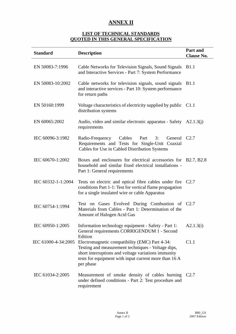
ANNEX II
LIST OF TECHNICAL STANDARDS QUOTED IN THIS GENERAL SPECIFICATION
Standard Description Part and Clause No.
EN 50083-7:1996
Cable Networks for Television Signals, Sound Signals and Interactive Services - Part 7: System Performance
B1.1
EN 50083-10:2002 Cable networks for television signals, sound signals and interactive services - Part 10: System performance for return paths
B1.1
EN 50160:1999
Voltage characteristics of electricity supplied by public distribution systems
C1.1
EN 60065:2002 Audio, video and similar electronic apparatus - Safety requirements
A2.1.3(j)
IEC 60096-3:1982 Radio-Frequency Cables Part 3: General Requirements and Tests for Single-Unit Coaxial Cables for Use in Cabled Distribution Systems
C2.7
IEC 60670-1:2002 Boxes and enclosures for electrical accessories for household and similar fixed electrical installations - Part 1: General requirements
B2.7, B2.8
IEC 60332-1-1:2004 Tests on electric and optical fibre cables under fire conditions Part 1-1: Test for vertical flame propagation for a single insulated wire or cable Apparatus
C2.7
IEC 60754-1:1994
Test on Gases Evolved During Combustion of Materials from Cables - Part 1: Determination of the Amount of Halogen Acid Gas
C2.7
IEC 60950-1:2005 Information technology equipment - Safety - Part 1: General requirements CORRIGENDUM 1 - Second Edition
A2.1.3(i)
IEC 61000-4-34:2005 Electromagnetic compatibility (EMC) Part 4-34: Testing and measurement techniques - Voltage dips, short interruptions and voltage variations immunity tests for equipment with input current more than 16 A per phase
C1.1
IEC 61034-2:2005
Measurement of smoke density of cables burning under defined conditions - Part 2: Test procedure and requirement
C2.7
Annex II Page 1 of 2
BRI_GS2007 Edition

Standard Description Part and Clause No.
IEC 62305-1:2006 & relevant current parts
Protection against lightning
B3.1, B4.2.3
ISO 5457:1999 Technical Product Documentation - Sizes and Layout of Drawing Sheets
A4.3.2
Annex II Page 2 of 2
BRI_GS2007 Edition

ANNEX III
TESTING INSTRUMENT REQUIRED FOR ACCEPTANCE TESTS OF
BROADCAST RECEPTION INSTALLATION
General Testing Instrument Required for Broadcast Reception Installation
Instrument
Test for which Instrument can
perform
Test Current
Test Voltage
Resolution
Accuracy
Min. Acceptable Insulation
Additional Requirements
Low Voltage Ohmmeter
1. Continuity of Conductor 2. Polarity
AC or DC Not less than 20 mA
Not less than 3 V not greater than 24 V
On low scale 0.01 2%
Insulation Resistance Tester
Insulation Resistance Test
DC 250 V for ELV circuits, 500 V for circuits up to 500 V
2% 250 V test - 250 k Ohms 500 V test - 500 k Ohms
1. Automatic capacitance discharge facility required 2. Capable of supplying an
output current of 1mA at its nominal voltage
Testing Instrument Required for Terrestrial Master Antenna Television System
Instrument
Frequency Bands
Measuring Ranges
Measuring Accuracy
Calibration Period
TV/FM Signal Strength Meter (suitable for analogue and digital signals)
FM 88 to 108 MHZ TV 5 to 900 MHZ
FM 20..... 126 dBμV TV 30......126 dBμV
FM less than ±2.5 dBμV TV less than ± 2.5 dBμV
1 year
TV/FM Signal Pattern Generator (suitable for analogue and digital signal generation)
5.....900 MHZ TV standards PAL I
625 lines, 25 full pictures/sec
Output : not less than 70 dBμV N.A. 1 year
Annex III Page 1 of 3
BRI_GS 2007 Edition
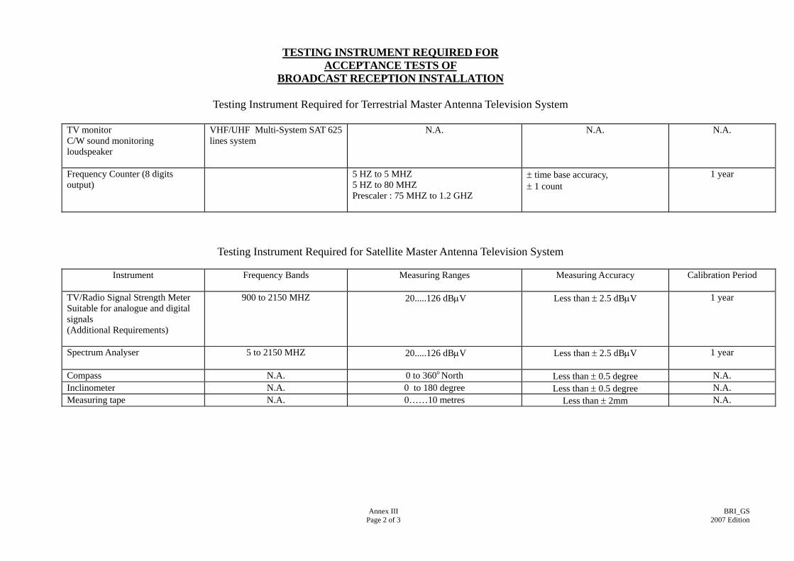
TESTING INSTRUMENT REQUIRED FOR ACCEPTANCE TESTS OF
BROADCAST RECEPTION INSTALLATION
Testing Instrument Required for Terrestrial Master Antenna Television System TV monitor C/W sound monitoring loudspeaker
VHF/UHF Multi-System SAT 625 lines system
N.A. N.A. N.A.
Frequency Counter (8 digits output)
5 HZ to 5 MHZ 5 HZ to 80 MHZ Prescaler : 75 MHZ to 1.2 GHZ
± time base accuracy, ± 1 count
1 year
Testing Instrument Required for Satellite Master Antenna Television System
Instrument
Frequency Bands Measuring Ranges Measuring Accuracy Calibration Period
TV/Radio Signal Strength Meter Suitable for analogue and digital signals (Additional Requirements)
900 to 2150 MHZ
20.....126 dBμV
Less than ± 2.5 dBμV
1 year
Spectrum Analyser 5 to 2150 MHZ
20.....126 dBμV
Less than ± 2.5 dBμV
1 year
Compass N.A. 0 to 360o North Less than ± 0.5 degree N.A. Inclinometer N.A. 0 to 180 degree Less than ± 0.5 degree N.A. Measuring tape N.A. 0……10 metres Less than ± 2mm N.A.
Annex III Page 2 of 3
BRI_GS 2007 Edition

ANNEX III
TESTING INSTRUMENT REQUIRED FOR ACCEPTANCE TESTS OF
BROADCAST RECEPTION INSTALLATION
Equipment Required for Fiber Optical Cable System
Instrument
Source Wavelength Measuring Ranges Measuring Accuracy Calibration Period
Fiber Optical Cable Fault & Power Meter
1310 nm 1550 nm
+3 to -55 dBm +3 to -55 dBm
± 0.25 dB at 23 C ± 0.25 dB at 23 C
1 year
Annex III Page 3 of 3
BRI_GS 2007 Edition

ANNEX IV
TYPICAL PROVISION OF BROADCAST RECEPTION SYSTEM MAIN TRUNKS
Appendix IV Page 1 of 1
BRI_GS2007 Edition