general specification for electrical installation in ... · general specification . for ....
TRANSCRIPT
GENERAL SPECIFICATION
FOR
ELECTRICAL INSTALLATION
IN
GOVERNMENT BUILDINGS
OF
THE HONG KONG SPECIAL ADMINISTRATIVE REGION
2017 EDITION
ARCHITECTURAL SERVICES DEPARTMENT THE GOVERNMENT OF THE HONG KONG SPECIAL ADMINISTRATIVE REGION

PREFACE This General Specification aims to lay down the technical requirements of materials and equipment, the standards of workmanship, the requirements on testing and commissioning, and operation and maintenance as well as requirements on document submissions for Electrical Installation in Government Buildings of the Hong Kong Special Administrative Region (HKSAR). The 2017 edition of this General Specification was developed from the 2012 edition (incorporating Corrigendum No. GSEE02-2012) by the Electrical Specialist Support Group that was established under the Building Services Branch Technical Information and Research & Development Committee of the Architectural Services Department (ArchSD). It incorporates updated international standards and codes as well as technological developments which find applications in Hong Kong. To be in line with the Department’s endeavour to reduce the environmental burden on our neighbours and to help preserving common resources while improving the quality of our service, this General Specification puts emphasis on green features and green practices for construction as well as initiatives for enhancement of client satisfaction on completed projects. With the benefit of information technology, electronic version of this edition is to be viewed on and free for download from the ArchSD Internet homepage. As part of the Government’s efforts to limit paper consumption, hard copies of this General Specification will not be put up for sale. The draft of the 2017 edition has been circulated to stakeholders within and external to the Government before finalisation. Nevertheless, the ArchSD welcomes comments on its contents at any time since the updating of this General Specification is a continuous process for the inclusion of any developments that can help meeting the needs of our community.

DISCLAIMER This General Specification is solely compiled for Electrical Installation carried out for or on behalf of the ArchSD in Government buildings of the HKSAR. There are no representations, either expressed or implied, as to the suitability of this General Specification for purposes other than that stated above. Users who choose to adopt this General Specification for their works are responsible for making their own assessments and judgement of all information contained here. The ArchSD does not accept any liability and responsibility for any special, indirect or consequential loss or damages whatsoever arising out of or in connection with the use of this General Specification or reliance placed on it. The materials contained in this document may not be pertinent or fully cover the extent of the installation in non-government buildings and there is no intimated or implied endorsement of the sales, supply and installation of the materials and equipment specified in this General Specification within the territory of the HKSAR.
Table of Contents Page 1 of 29
EE_GS 2017 Edition
TABLE OF CONTENTS
PART A SCOPE AND GENERAL REQUIREMENTS SECTION A1 SCOPE OF SPECIFICATION
A1.1 Installations to Comply with this General Specification A1.2 Scope of the Installations A1.3 Terms and Definitions A1.4 Singular and Plural
SECTION A2 STATUTORY OBLIGATIONS AND OTHER REGULATIONS A2.1 Statutory Obligations and Other Requirements
A2.1.1 Statutory Obligations A2.1.2 Other Requirements A2.1.3 Safety Requirements A2.1.4 Technical Standards
A2.2 Case of Conflict
SECTION A3 EXECUTION OF INSTALLATIONS A3.1 The International System of Units (SI) A3.2 Programme of Installations A3.3 Builder’s Work A3.4 Coordination of Installations A3.5 Cooperation with Other Contractors A3.6 Site Supervision A3.7 Sample Board A3.8 Advice of Order Placed A3.9 Record of Materials Delivery A3.10 Protection of Materials and Equipment A3.11 Painting
SECTION A4 DRAWINGS AND MANUALS A4.1 Drawings in Electronic Format A4.2 Installation Drawings
A4.2.1 Drawing Submission Schedule A4.2.2 Size of Installation Drawings A4.2.3 Contents of Installation Drawings A4.2.4 Builder’s Work Drawings A4.2.5 Manufacturer’s Shop Drawings
Table of Contents Page 2 of 29
EE_GS 2017 Edition
A4.2.6 Checking Drawings of Other Trades A4.3 As-built Drawings
A4.3.1 Submission of As-built Drawings A4.3.2 Size of As-built Drawings A4.3.3 Content of As-built Drawings A4.3.4 Framed Drawings
A4.4 Operation and Maintenance (O&M) Manual and User Manual A4.4.1 General A4.4.2 Presentation A4.4.3 Checking and Approval A4.4.4 Structure and Contents of O&M Manual A4.4.5 Structure and Contents of User Manual A4.4.6 Intellectual Property Rights

Table of Contents Page 3 of 29
EE_GS 2017 Edition
PART B INSTALLATION METHODOLOGY SECTION B1 GENERAL
B1.1 Workmanship B1.1.1 Tradesmen B1.1.2 Tool and Instrument B1.1.3 Safety on Site
B1.2 Label and Notice B1.2.1 Inscription of Label and Engraving B1.2.2 Material for Label B1.2.3 Fixing of Label B1.2.4 Engraving for Electrical Accessory B1.2.5 Warning Notice B1.2.6 Other Labels and Notices
B1.3 Guard and Railing for Moving or Rotating Parts of Equipment B1.4 Identification of Cable and Conduit B1.5 Fixing to Wooden Plug B1.6 Painting of Metal Work B1.7 Water Proofing B1.8 Provision of Spare Fuses in Main Switch Room
SECTION B2 INSTALLATION OF WIRING SYSTEMS B2.1 Wiring in Steel Conduit System
B2.1.1 Type of Cable B2.1.2 Concealed Steel Conduit System B2.1.3 Surface Conduit System B2.1.4 Minimum Size of Conduit B2.1.5 Flexible Conduit B2.1.6 Conduit Continuity B2.1.7 Joint in Conduits B2.1.8 Provision of Adaptable Box B2.1.9 Spacing between Conduits B2.1.10 Termination of Conduits at Metal Casing of
Equipment B2.1.11 Conduit Bend B2.1.12 Conduit Crossing Expansion Joint B2.1.13 Use of Extension Piece B2.1.14 Prevention of Ingress of Foreign Matters B2.1.15 Prevention of Accumulation of Water or Moisture
Table of Contents Page 4 of 29
EE_GS 2017 Edition
B2.1.16 Conduit Laid Direct in Ground B2.1.17 Fixing of Distance (Spacing) Saddle B2.1.18 Conduit Installed Outdoors or in Damp Situation B2.1.19 Swabbing Out of Conduit B2.1.20 Fire Barrier B2.1.21 Cable Capacity of Conduit B2.1.22 Method of Drawing Cables into Conduit B2.1.23 Segregation of Cables of Different Circuit
Categories B2.1.24 “Looping-in” Wiring System B2.1.25 Grouping of Cables in Conduit B2.1.26 Termination of Bonding Conductors at Conduit
Installation B2.2 Wiring in Steel Trunking System
B2.2.1 General B2.2.2 Provision of Cable Retaining Bar and Cable
Support B2.2.3 Cable Capacity of Trunking B2.2.4 Correction Factor of Grouping B2.2.5 Segregation of Cables of Different Circuit
Categories B2.2.6 Connection to Equipment B2.2.7 Connection to Distribution Board B2.2.8 Fixing of Surface Trunking B2.2.9 Cables through Trunking B2.2.10 Fire Barrier B2.2.11 Prevention of Electrolytic Action B2.2.12 Prevention of Ingress of Water
B2.3 Wiring in Plastic Conduit or Plastic Trunking System B2.3.1 General B2.3.2 Pliable Conduit B2.3.3 Joint in PVC Conduit B2.3.4 Plastic Boxes B2.3.5 Termination of PVC Conduit at Casing of
Equipment B2.3.6 Conduit Bend B2.3.7 Allowance for Thermal Expansion B2.3.8 Fixing of Trunking B2.3.9 Circuit Protective Conductor B2.3.10 Embedment of Concealed PVC Conduits
Table of Contents Page 5 of 29
EE_GS 2017 Edition
B2.4 Surface Wiring System B2.4.1 Type of Cable B2.4.2 Minimum Size of Live Conductors and CPC B2.4.3 Identification of Cable Core B2.4.4 Joint in Cable or Cord B2.4.5 Installation of Non-flexible Cable B2.4.6 Installation of Flexible Cable and Flexible Cord
B2.5 Tool and Workmanship B2.5.1 Approved Tool B2.5.2 Cutting in Metal Work for Conduit or in Trunking B2.5.3 Making Good of Damaged Coating
SECTION B3 INSTALLATION OF POWER CABLES, CABLE TRAYS AND
CABLE LADDERS B3.1 General
B3.1.1 Scope B3.1.2 Electromagnetic Interference
B3.2 Cable Mounted on Surface B3.3 Cable Laid in Enclosed Trench B3.4 Cable Enclosed in Duct
B3.4.1 General B3.4.2 Drawing-in of Cables B3.4.3 Internal Barrier B3.4.4 Fire Barrier B3.4.5 Draw-in Pit B3.4.6 Segregation of Cables of Different Circuit
Categories B3.4.7 Sealing of Duct Entry to Building
B3.5 Cable Buried Direct in Ground B3.5.1 Protection of Cable B3.5.2 Cable Marker
B3.6 Bending Radius of Cable B3.7 Cable Joint and Cable Termination
B3.7.1 General B3.7.2 Joint Box and Terminating Box B3.7.3 Identification at Joint or Termination B3.7.4 Earth Continuity across Joint B3.7.5 Straight-through Joint for Copper Conductors B3.7.6 Tee-joint for Copper Conductor B3.7.7 Joint for Aluminium Cables
Table of Contents Page 6 of 29
EE_GS 2017 Edition
B3.7.8 Termination of PVC-insulated or XLPE-insulated Cable with Copper Conductors
B3.7.9 Termination of PVC-insulated or XLPE-insulated Cable with Aluminium Conductors
B3.7.10 Use of Heat Shrinkable Tubing B3.7.11 Other Methods of Joint and Termination
B3.8 Special Requirements for Mineral Insulated Cables B3.8.1 Cable Route B3.8.2 Cable Support B3.8.3 Bending Radius B3.8.4 Cable Loop for Prevention of Vibration and Low
Temperature Cold Store B3.8.5 Cable Termination B3.8.6 Insulation Resistance B3.8.7 Bonding of Cable Sheath to Metalwork B3.8.8 Laying of Single-core Cables B3.8.9 Protection from Mechanical Damage
B3.9 Installation of Perforated Cable Trays B3.9.1 Connection between Adjacent Lengths of Tray B3.9.2 Cutting of Tray B3.9.3 Hole in Tray B3.9.4 Fixing of Tray B3.9.5 Fixing of Cable on Tray
B3.10 Installation of Wire Mesh Cable Trays B3.10.1 General B3.10.2 Supports B3.10.3 Bends B3.10.4 Earthing B3.10.5 Safety Working Load
B3.11 Installation of Cable Ladder B3.11.1 Dropout Plate for Cable Exit B3.11.2 Flexible (Expansion) Couplers across Building
Expansion Joint B3.11.3 Ladder Covers B3.11.4 End Connectors B3.11.5 Earthing B3.11.6 Minimum Inside Radius of All Bends B3.11.7 Supports B3.11.8 Safety Working Load
Table of Contents Page 7 of 29
EE_GS 2017 Edition
SECTION B4 INSTALLATION OF GENERAL LIGHTING AND POWER B4.1 Installation of Lighting System and Luminaires
B4.1.1 Pendant B4.1.2 Luminaire Mounted on Pattress B4.1.3 Ceiling Rose B4.1.4 Painting B4.1.5 Special Requirements for Outdoor Luminaires
B4.2 Installation of Wiring Accessories B4.3 Installation of Domestic Switches
B4.3.1 General B4.3.2 Lighting Switch B4.3.3 Time Switch B4.3.4 Application in Bathroom
B4.4 Installation of Socket Outlets B4.4.1 General B4.4.2 Shaver Supply Unit B4.4.3 Socket Outlet at Hazardous Area B4.4.4 Socket Outlet of Surface Conduit System B4.4.5 Socket Outlet for Different Voltage System B4.4.6 Application in Bathroom
B4.5 Installation of Measuring Instrument B4.5.1 Mounting of Current Transformers Associated
with Watt-hour Meter B4.5.2 Identification of Instrument B4.5.3 Mounting Position of Selector Switch
SECTION B5 INSTALLATION OF DOMESTIC APPLIANCES
B5.1 General B5.1.1 Connection to Appliances B5.1.2 (NOT USED) B5.1.3 Engraving for Identification B5.1.4 Earthing of Appliance B5.1.5 Appliance Requiring Exclusive Circuit
B5.2 Ceiling Fan and Ceiling-mounted Rotary Fan B5.2.1 Method of Supply B5.2.2 Fixing of Fan B5.2.3 Fan Regulator
B5.3 Wall-mounted Fan B5.4 Exhaust Fan
B5.4.1 Fixing of Fan
Table of Contents Page 8 of 29
EE_GS 2017 Edition
B5.4.2 Method of Supply B5.5 Electric Fire or Heater
B5.5.1 Wall-mounted Radiator B5.5.2 Panel Fire B5.5.3 Tubular Heater
B5.6 Water Heater and Water Boiler B5.6.1 Oversink Water Heater B5.6.2 Other Type of Water Heater B5.6.3 Water Boiler
B5.7 Tea Urn B5.8 Household Electric Cooker B5.9 Hand/Face Dryer B5.10 Room Cooler
B5.10.1 Method of Supply B5.10.2 Position of Connection Unit
B5.11 Refrigerator
SECTION B6 INSTALLATION OF BUSBAR TRUNKING SYSTEM B6.1 General B6.2 Site Storage and Protection B6.3 Busbar Identification B6.4 Joint in Busbar B6.5 Expansion Unit B6.6 Feeder Unit B6.7 Tap-off Unit Connection B6.8 Fire Barrier B6.9 Busbar Trunking Accessories B6.10 Support of Busbar Trunking System B6.11 Earthing B6.12 Requirements for Air-insulated Busbar Trunking System
B6.12.1 Application B6.12.2 Busbar Supports B6.12.3 Tap-off B6.12.4 Fire Barrier B6.12.5 Mounting Brackets
B6.13 Requirement for All Insulated Busbar Trunking System B6.13.1 Application B6.13.2 Busbar Jointing B6.13.3 Expansion Unit B6.13.4 Tap-off Unit
Table of Contents Page 9 of 29
EE_GS 2017 Edition
B6.13.5 Supporting Hangers and Fixing Brackets
SECTION B7 INSTALLATION OF EARTHING SYSTEM B7.1 General B7.2 Main Earthing Terminal B7.3 Earth Electrode
B7.3.1 Types of Earth Electrode B7.3.2 Rod Electrode B7.3.3 Tape Electrode B7.3.4 Plate Electrode B7.3.5 Electrode in Deep Bored Hole B7.3.6 Connection between Electrodes
B7.4 Earthing Conductor B7.4.1 Conductor Material B7.4.2 Connection to Electrodes
B7.5 Main Equipotential Bonding Conductor B7.5.1 Conductor Material B7.5.2 Bonding Position B7.5.3 Bonding Method
B7.6 Supplementary Bonding Conductor B7.6.1 Conductor Material B7.6.2 Application in Bathroom B7.6.3 Application in Other Areas B7.6.4 Bonding Method
B7.7 Circuit Protective Conductor (CPC) B7.7.1 General B7.7.2 CPC for Socket Outlet B7.7.3 CPC for Flexible Conduit B7.7.4 CPC for Busbar Trunking B7.7.5 CPC for Ring Final Circuit
B7.8 Joints in Protective Conductors B7.9 Identification and Labelling
B7.9.1 Colour Identification B7.9.2 Label for Earthing and Bonding Connections
B7.10 Sizing of Protective Conductor B7.10.1 General B7.10.2 Equipotential Bonding Conductor
B7.11 Earth Fault Loop Impedance B7.11.1 Automatic Disconnection Time B7.11.2 Maximum Earth Loop Impedance
Table of Contents Page 10 of 29
EE_GS 2017 Edition
B7.11.3 Condition for Compliance B7.12 Use of Residual Current-operated Circuit Breaker
B7.12.1 General B7.12.2 Application in Household Installation B7.12.3 Equipment Outside an Equipotential Zone B7.12.4 Circuits in Bathroom
SECTION B8 MISCELLANEOUS INSTALLATIONS
B8.1 Telecommunication Systems B8.1.1 Scope B8.1.2 Conduit for Telephone, Computer Network,
Inter-communication and PA Systems B8.1.3 Outlet Box for Telephone Point B8.1.4 Outlet Box for Computer Point B8.1.5 Outlet Box for Inter-communication and PA
System B8.1.6 Conduit for Staff Paging System B8.1.7 Conduit for Broadcast Reception System B8.1.8 Outlet Box for Broadcast Reception System
B8.2 Bell and Audible Warning System B8.2.1 Class-change Bell System for Schools B8.2.2 Bell for Mains Voltage B8.2.3 Call Bell and Door Bell Systems B8.2.4 Bell and Buzzer for Extra Low Voltage B8.2.5 Bell Transformer B8.2.6 Call Bell Push B8.2.7 Mounting of Call Bell Push B8.2.8 Table-type Push B8.2.9 Table-type Push in Concealed Conduit Installation B8.2.10 Bell Indicator B8.2.11 Segregation of Circuits
B8.3 Installation in Hazardous Areas B8.3.1 General B8.3.2 Electrical Equipment Selection B8.3.3 Wiring System B8.3.4 Conduit Fitting, Cable Glands, Terminal Box and
Enclosure B8.3.5 Screw or Bolt B8.3.6 Luminaire B8.3.7 Conduit Pendant
Table of Contents Page 11 of 29
EE_GS 2017 Edition
B8.3.8 Cables or Conduits Passing through Floor, Wall or Partition
B8.3.9 Precautions to Prevent Passage of Inflammables Gases or Vapours
B8.3.10 Equipotential Bonding of Conduit B8.4 External Lighting System
B8.4.1 Scope B8.4.2 Specification and Drawing B8.4.3 Luminaire B8.4.4 Construction of Lamp Pole B8.4.5 Foundation of Lamp Pole B8.4.6 Service Box B8.4.7 Underground Cable to Pole B8.4.8 Cable between Service Box and Luminaire B8.4.9 Switch Fitted to Pole B8.4.10 Control Gear for Discharge Lighting B8.4.11 Testing of Illumination Level B8.4.12 Numbering of Lamp Pole
B8.5 Lightning Protection System B8.5.1 Installation of Lightning Protection System B8.5.2 Scope B8.5.3 Type of Lightning Protection System B8.5.4 Air Termination B8.5.5 Down Conductor B8.5.6 Test Joint B8.5.7 Earth Termination B8.5.8 Spacer Saddle B8.5.9 Connection to Earth Termination B8.5.10 Bonding to Other Services B8.5.11 Bond B8.5.12 Joint in Conductors B8.5.13 Testing
SECTION B9 INSTALLATION OF ELECTRIC MOTORS AND HIGH
VOLTAGE EQUIPMENT B9.1 Low Voltage-Electric Motors
B9.1.1 Maintenance Access and Safety B9.1.2 Terminals B9.1.3 Anti-condensation Heater B9.1.4 Belt Drives and Pulleys
Table of Contents Page 12 of 29
EE_GS 2017 Edition
B9.1.5 Protective Guards B9.1.6 Warning Label
B9.2 Motor Switchgear, Starter and Control Panels B9.2.1 General B9.2.2 Local Motor Control Panels B9.2.3 Motor Control Switchboard
B9.3 High Voltage-General B9.4 High Voltage-Electric Motors
B9.4.1 Motor Foundation B9.4.2 Provision for Cabling and Termination
B9.5 High Voltage Motor Control Switchboard B9.5.1 General Requirements B9.5.2 Primary Busbars and Connections B9.5.3 Anti-condensation Heaters B9.5.4 Cables Boxes B9.5.5 Labels and Warning Notice
B9.6 High Voltage Auto-transformers B9.7 High Voltage Power Factor Correction Capacitors B9.8 High Voltage Power Cables
Table of Contents Page 13 of 29
EE_GS 2017 Edition
PART C MATERIAL AND EQUIPMENT SPECIFICATION SECTION C1 GENERAL
C1.1 Material and Equipment C1.1.1 International Standards C1.1.2 Other Standard Specifications C1.1.3 Service Conditions C1.1.4 Selection of Equipment C1.1.5 Equipment Catalogue and Manufacturer’s
Specification C1.2 Voltage Covered by this Specification C1.3 Insulating Material C1.4 Minimum Size of Cable Conductor C1.5 Use of PVC-Insulated Cable at Low Temperature C1.6 Fixing Screw and Bolt C1.7 Sheet Metal Work C1.8 Cable Markers in addition to Cable Colour Identification
SECTION C2 WIRING SYSTEM: CABLES, CONDUITS, TRUNKING AND ACCESSORIES C2.1 Cables in Wiring System
C2.1.1 General C2.1.2 Non-sheathed Cables C2.1.3 Sheathed Cables C2.1.4 Flexible Cables C2.1.5 Conductor C2.1.6 Fire Performance of Fire Resistant Cables
C2.2 Steel Conduit and Accessories C2.2.1 Steel Conduit C2.2.2 Steel Flexible Conduit C2.2.3 Steel Conduit Fitting C2.2.4 Metal Boxes for Electrical Accessories C2.2.5 Class of Protection against Corrosion C2.2.6 Screw
C2.3 Plastic or PVC Conduit and Accessories C2.3.1 Rigid Conduit and Conduit Fittings C2.3.2 Pliable Conduit C2.3.3 Plastic or PVC Conduit Boxes C2.3.4 Plastic Couplers
Table of Contents Page 14 of 29
EE_GS 2017 Edition
C2.4 Steel Trunking and Accessories C2.4.1 Steel Trunking C2.4.2 Class of Protection against Corrosion C2.4.3 Construction C2.4.4 Dimension C2.4.5 Connection between Lengths of Trunking C2.4.6 Steel Surface Trunking Cover C2.4.7 Screw
C2.5 Plastic or PVC Trunking and Accessories
SECTION C3 POWER CABLES AND ASSOCIATED CABLING FACILITIES C3.1 General C3.2 Types of Power Cables C3.3 Conductor C3.4 Armour C3.5 Cable Terminations C3.6 Fire Performance of Fire Resistant Cables C3.7 Identification of Core C3.8 Special Requirements for Mineral Insulated (MI) Cable
C3.8.1 Outer Covering C3.8.2 Restriction of Use C3.8.3 Cable Saddle and Clip
C3.9 Cable Duct C3.10 Perforated Metal Cable Tray
C3.10.1 Material C3.10.2 Dimensions of Tray C3.10.3 Bend Piece C3.10.4 Perforation on Bend C3.10.5 Tee Piece C3.10.6 Cable Tray Accessory
C3.11 Wire Mesh Cable Tray (Cable Basket) C3.11.1 General C3.11.2 Material C3.11.3 Fittings and Accessories C3.11.4 Construction of Wire Mesh Cable Tray
C3.12 Cable Ladder C3.12.1 Material C3.12.2 Fittings and Accessories C3.12.3 Construction of Cable Ladder
Table of Contents Page 15 of 29
EE_GS 2017 Edition
SECTION C4 WIRING ACCESSORIES AND MEASURING INSTRUMENTS C4.1 Wiring Accessories - General C4.2 Domestic Switches
C4.2.1 General C4.2.2 Lighting Switch C4.2.3 Double Pole Switch for Appliance C4.2.4 Sparkless Switch C4.2.5 Time Switch
C4.3 Socket Outlets C4.3.1 General C4.3.2 Shaver Supply Unit C4.3.3 Plug
C4.4 Connection Units C4.4.1 (NOT USED) C4.4.2 Switched or Unswitched Fused Connection Unit
C4.5 Insulated Terminal Block C4.6 Lighting System Accessories
C4.6.1 Luminaire Track System C4.6.2 Photocell Device C4.6.3 Ceiling Rose C4.6.4 Lampholder
C4.7 Measuring Instrument C4.7.1 Watt-hour Meter C4.7.2 Ammeter and Voltmeter C4.7.3 Current Transformer C4.7.4 Selector Switch for Ammeter C4.7.5 Selector Switch for Voltmeter C4.7.6 Meter Chamber
C4.8 Occupancy and Daylight Sensor C4.8.1 General C4.8.2 Passive Infrared (PIR) Sensor C4.8.3 Ultrasonic Sensor C4.8.4 Dual Technology Sensor C4.8.5 Daylight Sensor
SECTION C5 SWITCHGEAR AND ASSOCIATED EQUIPMENT
C5.1 General C5.1.1 Scope C5.1.2 Service Condition
Table of Contents Page 16 of 29
EE_GS 2017 Edition
C5.1.3 Short-circuit Rating and Continuous Current Rating
C5.1.4 Voltage Rating C5.1.5 Degree of Protection for Enclosure C5.1.6 Material C5.1.7 ON and OFF Indication C5.1.8 Identification of Circuit
C5.2 Switch, Disconnector, Fuse-switch and Switch-fuse C5.2.1 Scope of Switch C5.2.2 General C5.2.3 Operating Mechanism C5.2.4 Construction C5.2.5 Operating Performance C5.2.6 Utilisation Category C5.2.7 Padlocking Facility
C5.3 Circuit Breaker - General C5.3.1 Scope of Circuit Breaker C5.3.2 Number of Poles C5.3.3 Operating Mechanism C5.3.4 Casing C5.3.5 Current Rating
C5.4 Air-circuit Breaker (ACB) C5.4.1 General C5.4.2 Performance Characteristic C5.4.3 Closing and Tripping Operation C5.4.4 Racking Gear C5.4.5 Interlocking Facility C5.4.6 Main Isolating Contacts and Safety Shutter C5.4.7 Contact
C5.5 Moulded Case Circuit Breaker (MCCB) C5.5.1 General C5.5.2 Operating Characteristic C5.5.3 Performance Characteristic C5.5.4 Shunt Trip Release C5.5.5 Locking Facility
C5.6 Miniature Circuit Breaker (MCB) C5.6.1 General C5.6.2 Operating Characteristic C5.6.3 Short Circuit Breaking Capacity
Table of Contents Page 17 of 29
EE_GS 2017 Edition
C5.7 Residual Current-operated Circuit Breaker without Integral Overcurrent Protection (RCCB) and Residual Current- operated Circuit Breaker with Integral Overcurrent Protection (RCBO) C5.7.1 RCCB – General C5.7.2 RCCB – Electrical and Operating Characteristics C5.7.3 RCCB – Test Device C5.7.4 RCBO – General C5.7.5 RCBO – Electrical and Operating Characteristics C5.7.6 RCBO – Test Device
C5.8 Fuse C5.8.1 Scope of Fuse C5.8.2 General C5.8.3 Fuse Carrier and Holder C5.8.4 (NOT USED) C5.8.5 Fuse Ratings and Dimensions
C5.9 Busbar Chamber C5.9.1 General C5.9.2 Construction C5.9.3 Colour Identification of Busbar C5.9.4 Interconnection to Other Equipment
C5.10 Distribution Board - General C5.10.1 Scope of Distribution Board C5.10.2 Construction of Enclosure C5.10.3 Arrangement of Component Parts C5.10.4 Busbar C5.10.5 Earthing Terminal C5.10.6 Provision of Spare Ways C5.10.7 Shrouding of Live Part C5.10.8 Certification and Verification Test
C5.11 MCCB Distribution Board C5.11.1 General C5.11.2 Busbar
C5.12 MCB Distribution Board C5.12.1 General C5.12.2 Construction C5.12.3 Method of Mounting
C5.13 Voltage Dip Ride-through Device C5.13.1 Constant Voltage Transformer C5.13.2 Static Tap Switcher Voltage Regulator
Table of Contents Page 18 of 29
EE_GS 2017 Edition
C5.13.3 Voltage Dip Ride-through Inverter C5.14 Electromechanical Contactors
C5.14.1 General C5.14.2 Performance Requirements C5.14.3 Co-ordination with Short-circuit Protective
Devices C5.14.4 Control Circuit
C5.15 Changeover Switch C5.16 Active Harmonic Filter
C5.16.1 General Requirements C5.16.2 Performance Requirements C5.16.3 Construction
C5.17 Surge Protection Device C5.17.1 General Requirements C5.17.2 Performance Requirements C5.17.3 Construction
C5.18 Solid State Soft Motor Starter C5.18.1 General Requirements C5.18.2 Performance Requirements C5.18.3 Selection of Softstarter and Operating Precautions
C5.19 Variable Speed Drives for Centrifugal Fans and Pumps C5.19.1 General Requirements C5.19.2 Performance Requirements C5.19.3 Construction
C5.20 Digital Multifunction Power Meter C5.20.1 General Requirements C5.20.2 Technical Requirements
C5.21 Charger and Battery Set C5.21.1 General Requirements C5.21.2 Technical Requirements C5.21.3 Construction C5.21.4 Selection Criteria
C5.22 Power Factor Correction Equipment C5.22.1 General Requirements C5.22.2 Requirements of the Components
C5.23 Digital Protection Relay C5.23.1 General Requirements C5.23.2 Technical Requirements
C5.24 Digital Power Analyser C5.24.1 General Requirements
Table of Contents Page 19 of 29
EE_GS 2017 Edition
C5.24.2 Technical Requirements C5.25 Electric Motors
C5.25.1 General C5.25.2 Insulation Test C5.25.3 Starting Torque and Current C5.25.4 Maintenance Access and Safety C5.25.5 Noise and Vibration C5.25.6 Minimum Motor Efficiency C5.25.7 Continuous Rating C5.25.8 Tachometers C5.25.9 Terminals C5.25.10 Anti-condensation Heater C5.25.11 Belt Drives and Pulleys C5.25.12 Protective Guards C5.25.13 Motor Fed by Converter
C5.26 Motor Switchgear, Starters and Control Panel C5.26.1 General C5.26.2 Local Motor Control Panels C5.26.3 Motor Control Switchboard C5.26.4 Motor Starters
SECTION C6 BUSBAR TRUNKING SYSTEM
C6.1 General C6.2 Busbar Trunking Construction C6.3 Busbar Insulation C6.4 Busbar C6.5 Feeder Unit C6.6 Tap-off Units C6.7 Busbar Expansion Unit C6.8 Fire Barrier in Busbar Trunking System C6.9 Busbar Trunking Accessories C6.10 Certification and Verification Test C6.11 Requirement for Air-insulated Busbar Trunking System
C6.11.1 Busbar Enclosure C6.11.2 Busbar Supports C6.11.3 Busbar Jointing C6.11.4 Suspension Unit, Flexible Joint and Stop-end Unit C6.11.5 Tap-off Unit
C6.12 Requirement for All Insulated Busbar Trunking System C6.12.1 Busbar Enclosure
Table of Contents Page 20 of 29
EE_GS 2017 Edition
C6.12.2 Busbar Insulation C6.12.3 Tap-off Units C6.12.4 Joint in Busbar Trunking System
SECTION C7 FLUORESCENT LUMINAIRE AND LAMP C7.1 General C7.2 Type of Luminaires C7.3 Group 1 Luminaires C7.4 Group 2 - Special Luminaires C7.5 Group 3 - Self-contained Emergency Fluorescent Luminaires
C7.5.1 General C7.5.2 Standards C7.5.3 Functional Requirements C7.5.4 Construction
C7.6 (NOT USED) C7.7 Fluorescent Lamps C7.8 Electronic Ballasts
C7.8.1 General C7.8.2 Construction C7.8.3 Performance Requirements C7.8.4 Additional Requirements for Dimmable Electronic
Ballasts
SECTION C8 HIGH INTENSITY DISCHARGE LUMINAIRE AND LAMP C8.1 General C8.2 High Pressure Sodium Vapour Discharge Lamp (SON-T and
SON-E or LBS: HST and HSE) C8.3 Elliptical High Pressure Mercury Vapour Discharge Lamp
(MBF or LBS : HME) C8.4 Linear Metal Halide/Linear High Pressure Sodium Lamp C8.5 Luminaire for Floodlighting
C8.5.1 General C8.5.2 Construction C8.5.3 Lamps
SECTION C9 LIGHT EMITTING DIODE LUMINAIRE & DRIVER C9.1 General C9.2 Electronic Driver C9.3 LED Module C9.4 Performance Requirements
Table of Contents Page 21 of 29
EE_GS 2017 Edition
SECTION C10 DOMESTIC APPLIANCES
C10.1 General C10.1.1 Compliance with Regulation C10.1.2 General Requirements C10.1.3 Technical Literature
C10.2 900 mm, 1,200 mm and 1,400 mm Ceiling Fan C10.2.1 General Requirements C10.2.2 Performance Requirements C10.2.3 Construction
C10.3 400 mm Sweep Auto Cycle/Oscillating Fan C10.3.1 General Requirements C10.3.2 Performance Requirements C10.3.3 Construction
C10.4 400 mm Sweep Wall Fan C10.4.1 General Requirements C10.4.2 Performance Requirements C10.4.3 Construction
C10.5 400 mm Sweep Desk Fan C10.5.1 General Requirements C10.5.2 Performance Requirements C10.5.3 Construction
C10.6 400 mm Sweep Pedestal Fan C10.6.1 General Requirements C10.6.2 Performance Requirements C10.6.3 Construction
C10.7 Domestic Exhaust Fan C10.7.1 General Requirements C10.7.2 Performance Requirements C10.7.3 Construction
C10.8 Propeller Fan – Ring Mounted Type C10.8.1 General Requirements C10.8.2 Performance Requirements C10.8.3 Construction
C10.9 Fume Cupboard Exhaust Fan C10.9.1 General Requirements C10.9.2 Performance Requirements C10.9.3 Construction
C10.10 1 kW Electric Fire, Wall Mounted Type C10.10.1 General Requirements
Table of Contents Page 22 of 29
EE_GS 2017 Edition
C10.10.2 Performance Requirements C10.10.3 Construction
C10.11 2 kW Convector Fire C10.11.1 General Requirements C10.11.2 Performance Requirements C10.11.3 Construction
C10.12 2 kW Oil-filled Electric Radiator C10.12.1 General Requirements C10.12.2 Performance Requirements C10.12.3 Construction
C10.13 300 mm and 1,200 mm Single Tubular Heater Complete with Wire Guard C10.13.1 General Requirements C10.13.2 Performance Requirements C10.13.3 Construction
C10.14 10-Litre Open-outlet Type, Electric Sink Water Heater C10.14.1 General Requirements C10.14.2 Performance Requirements C10.14.3 Construction
C10.15 90-Litre and 135-Litre Thermal Storage Electric Water Heater C10.15.1 General Requirements C10.15.2 Performance Requirements C10.15.3 Specific Safety Requirements C10.15.4 Construction
C10.16 Electric Tea Urn C10.16.1 General Requirements C10.16.2 Performance Requirements C10.16.3 Construction
C10.17 Electric Kettle 3.5-4.5 Litres C10.17.1 General Requirements C10.17.2 Performance Requirements C10.17.3 Construction
C10.18 Mains-supply Drinking Water Dispenser for "Cold" Water C10.18.1 General Requirements C10.18.2 Performance Requirements C10.18.3 Construction
C10.19 Domestic Electric Cooker (Table Model) C10.19.1 General Requirements C10.19.2 Performance Requirements C10.19.3 Construction
Table of Contents Page 23 of 29
EE_GS 2017 Edition
C10.20 Domestic Electric Cooker (Four Radiant Plates Type) C10.20.1 General Requirements C10.20.2 Performance Requirements C10.20.3 Construction
C10.21 Electric Hot Plate C10.21.1 General Requirements C10.21.2 Performance Requirements C10.21.3 Construction
C10.22 10-Persons and 15-Persons Electric Rice Cooker C10.22.1 General Requirements C10.22.2 Performance Requirements C10.22.3 Construction
C10.23 2 kW Electric Toaster C10.23.1 General Requirements C10.23.2 Performance Requirements C10.23.3 Construction
C10.24 Electric Hand/Face Dryer C10.24.1 General Requirements C10.24.2 Performance Requirements C10.24.3 Construction
C10.25 (NOT USED) C10.26 Wall Clock Battery-operated
C10.26.1 General Requirements C10.26.2 Performance Requirements C10.26.3 Construction
C10.27 Electric Dry Iron C10.27.1 General Requirements C10.27.2 Performance Requirements C10.27.3 Construction
C10.28 Vacuum Cleaner C10.28.1 General Requirements C10.28.2 Performance Requirements C10.28.3 Construction
C10.29 Floor Polisher C10.29.1 General Requirements C10.29.2 Performance Requirements C10.29.3 Construction
C10.30 7-Litres and 9-Litres Dehumidifier C10.30.1 General Requirements C10.30.2 Performance Requirements
Table of Contents Page 24 of 29
EE_GS 2017 Edition
C10.30.3 Construction C10.31 Room Cooler
C10.31.1 Type of Room Cooler C10.31.2 General Requirements C10.31.3 Performance Requirements C10.31.4 Construction
C10.32 Refrigerator C10.32.1 Type of Refrigerator C10.32.2 General Requirements C10.32.3 Performance Requirements C10.32.4 Construction
C10.33 LED Table Lamp C10.33.1 General Requirements C10.33.2 Safety Requirements C10.33.3 Performance Requirements C10.33.4 Electrical Requirements C10.33.5 Mechanical Requirements C10.33.6 Testing Standards for Compliance
SECTION C11 LOW VOLTAGE CUBICLE SWITCHBOARD C11.1 General C11.2 Design Requirements C11.3 Performance Requirements C11.4 Construction and Finish C11.5 Electricity Characteristics of the Switchboard C11.6 Service Conditions C11.7 Busbars, Wiring and Earthing C11.8 Circuit Breakers, Fuseswitches and Automatic Changeover
Switches C11.9 Metering, Protective Relays and Indicating Lamps C11.10 Supply Company Metering C11.11 Labels C11.12 Cable Arrangements C11.13 Automatic Interlocking Facility C11.14 Ancillary Equipment C11.15 Certification and Verification Test C11.16 Operation Instruction/Drawing at the Main Switch Room C11.17 Inspection and Testing for Low Voltage Cubicle Switchboard
Installation C11.18 Requirements during Maintenance Period
Table of Contents Page 25 of 29
EE_GS 2017 Edition
SECTION C12 DIESEL GENERATING SET INSTALLATION
C12.1 Requirements of Diesel Generating Sets C12.1.1 Generating Set Rating C12.1.2 General Requirements of Diesel Engine C12.1.3 General Requirements of Alternator C12.1.4 Starting System C12.1.5 Electrical Loads C12.1.6 Suitability for Cold Starting and Step Load
Acceptance C12.1.7 Radio Interference Suppression C12.1.8 Painting C12.1.9 Baseframe Assembly C12.1.10 Welding C12.1.11 Structural Steel
C12.2 Construction of Control Cubicle C12.3 Operation Requirement
C12.3.1 Automatic Operation C12.3.2 Protection
C12.4 Control Requirement C12.4.1 Instruments and Functions for Control Cubicle C12.4.2 Interfacing with CCMS System
C12.5 Installation of Diesel Generating Sets C12.5.1 Position C12.5.2 Guards and Insulations C12.5.3 Air-ducts C12.5.4 Engine Exhaust System C12.5.5 Electrical Works
C12.6 Engine Cooling System Using Remote Radiator C12.6.1 General C12.6.2 Remote Radiators C12.6.3 Heat Exchangers C12.6.4 Water Circulating Pumps C12.6.5 Expansion Tank C12.6.6 Pipework and Valve C12.6.7 Hydraulic Test C12.6.8 Power Supply and Control System
C12.7 Fuel Supply System C12.7.1 Underground Horizontal Fuel Storage Tank C12.7.2 Daily Services Fuel Tank
Table of Contents Page 26 of 29
EE_GS 2017 Edition
C12.7.3 Fuel transfer Pumping System C12.7.4 Pipeworks and Fittings C12.7.5 Diesel Fuel Level Switches
C12.8 Acoustic Treatment Installation C12.8.1 Performance Requirements C12.8.2 Scope of Work C12.8.3 Installation of the Acoustic Treatment System
C12.9 Exhaust Fan for Emergency Generator Room C12.10 Lifting Hoist C12.11 Warning Sign C12.12 Schematic Diagrams C12.13 Testing
C12.13.1 Testing of Diesel Generating Sets C12.13.2 Testing of Control Cubicle C12.13.3 Testing of Daily Service Tank, Fuel Storage Tank
and Pipework C12.13.4 Testing of Noise Control System C12.13.5 Testing of Exhaust Fan
C12.14 Submission to the Authorities
SECTION C13 HIGH VOLTAGE SWITCHGEAR AND EQUIPMENT C13.1 High Voltage – General C13.2 High Voltage – Electric Motors
C13.2.1 Performance Requirements C13.2.2 Enclosure C13.2.3 Thermal Insulation & Characteristics C13.2.4 Motor Stators & Windings C13.2.5 Rotor C13.2.6 Bearings C13.2.7 Motor Foundation C13.2.8 Provision for Cabling and Termination C13.2.9 Motor Termination Boxes C13.2.10 Markings and Data Plates C13.2.11 Temperature Detectors for Motor Protection
C13.3 High Voltage – Motor Control Switchboards C13.3.1 General Requirements C13.3.2 General Construction C13.3.3 Primary Busbars and Connections C13.3.4 Circuit Breakers C13.3.5 Earthing and Earthing Devices
Table of Contents Page 27 of 29
EE_GS 2017 Edition
C13.3.6 Testing Facilities C13.3.7 Mechanical Indication C13.3.8 Auxiliary Switches C13.3.9 Anti-Condensation Heaters C13.3.10 Current Transformers C13.3.11 Voltage Transformers C13.3.12 Cables Boxes C13.3.13 Protective Relays C13.3.14 Control and Timer Relays C13.3.15 Indicating Instruments C13.3.16 Labels and Warning Notice C13.3.17 Ancillary Equipment C13.3.18 Operation Diagram
C13.4 High Voltage – Auto-transformers C13.4.1 General C13.4.2 Rating C13.4.3 Insulation C13.4.4 Transformer Windings C13.4.5 Tap Changers C13.4.6 Internal Earthing of Transformers C13.4.7 Enclosure C13.4.8 Finishes C13.4.9 Rating Plates and Diagrams C13.4.10 Cable Boxes
C13.5 High Voltage – Power Factor Correction Capacitors C13.6 High Voltage – Power Cables
C13.6.1 General C13.6.2 Cross-Linked Polyethylene (XLPE) Cables C13.6.3 Conductors C13.6.4 Cable Terminations
SECTION C14 COMPUTERIZED LIGHTING MANAGEMENT SYSTEM C14.1 General C14.2 System Requirement C14.3 Communication Bus C14.4 Lighting Control Modules
Table of Contents Page 28 of 29
EE_GS 2017 Edition
PART D INSPECTION, TESTING AND COMMISSIONING DURING CONSTRUCTION PERIOD
SECTION D1 GENERAL REQUIREMENTS
D1.1 General D1.2 Methods and Procedures D1.3 Notices of Inspection, Testing and Commissioning Works D1.4 Labour and Materials D1.5 Inspection, Measuring and Testing Equipment D1.6 Readiness for Inspection, Testing and Commissioning D1.7 "Type-test" Certificate D1.8 Off-site Tests / Factory Tests D1.9 Site tests
SECTION D2 INSPECTION D2.1 Inspection of Materials and Equipment Delivered to Site D2.2 Visual Inspection and Checking D2.3 Handover Inspection D2.4 Inspection and Functional Test of Installed Works
SECTION D3 TESTING AND COMMISSIONING D3.1 General D3.2 Procedures, Standards and Requirements D3.3 Master Programme for Testing and Commissioning Works D3.4 Documents and Deliverables D3.5 Testing of Emergency Lighting, Exit Sign and Emergency
Generator Installations
Table of Contents Page 29 of 29
EE_GS 2017 Edition
PART E TRAINING, INSPECTION, ATTENDANCE, OPERATION AND MAINTENANCE DURING MAINTENANCE PERIOD
SECTION E1 GENERAL REQUIREMENTS E1.1 General E1.2 Completion of Outstanding and Defective Works E1.3 Repair and Maintenance Records
SECTION E2 TRAINING TO USERS AND OPERATION AND MAINTENANCE AGENTS E2.1 General
SECTION E3 INSPECTION, ATTENDANCE, OPERATION AND MAINTENANCE REQUIREMENTS E3.1 Response and Attendance To Emergency and Fault Calls E3.2 Maintenance Schedule E3.3 Inspection During Maintenance Period E3.4 Joint Inspection at the End of Maintenance Period E3.5 Final Inspection before the End of Maintenance Period for
Low Voltage Cubicle Switchboard E3.6 Follow Up Action After Emergency and Fault Cases
ANNEX I LIST OF TECHNICAL STANDARDS QUOTED IN THIS GENERAL SPECIFICATION
Section A1 Page 1 of 3
EE_GS 2017 Edition
PART A – SCOPE AND GENERAL REQUIREMENTS
SECTION A1
SCOPE OF SPECIFICATION
A1.1 INSTALLATIONS TO COMPLY WITH THIS GENERAL SPECIFICATION The Electrical Installation shall comply with this General Specification which details the intrinsic properties (including materials and workmanship) of the Installations, in so far as it is not overridden by the Conditions, Particular Specification, Drawings and/or written instructions of the Supervising Officer.
A1.2 SCOPE OF THE INSTALLATIONS This General Specification, Particular Specification, Tender Equipment Schedule and Drawings detail the performance requirements of the Installations. The Installations to be carried out in accordance with this General Specification shall include the design where specified, installation and supply of all materials necessary to form a complete Installations including any necessary tests, adjustments, commissioning and maintenance as prescribed and all other incidental sundry components together with the necessary labour for installing such components, for the proper operation of the Installations.
A1.3 TERMS AND DEFINITIONS In this General Specification, all words and expressions shall have the meaning as assigned to them under the Conditions unless otherwise provided herein. The following words or expressions shall have the meanings assigned to them except when the context otherwise requires: ArchSD BS BS EN BSB Building Contractor
Architectural Services Department, the Government of the Hong Kong Special Administrative Region British Standards, including British Standard Specifications and British Standard Codes of Practice, published by the British Standards Institution. European Standard adopted as British Standard The Building Services Branch of the ArchSD, the Government of the Hong Kong Special Administrative Region. The contractor employed by the Employer for the execution of the Works or the Specialist Contractor separately employed by the Employer to execute the Specialist Works as appropriate.
Section A1 Page 2 of 3
EE_GS 2017 Edition
Conditions CSA EE Contractor Electricity Supplier EMSD EN FSD IEC IET Installations ISO O&M or equivalent standards
The “Conditions of Contract” as defined in the Contarct. For Nominated Sub-contract works, the “Main Contract Conditions” and the “Sub-contract Conditions” as defined in the Nominated Sub-contract as appropriate Cross-sectional area of a conductor The Nominated Sub-contractor or the Specialist Sub-contractor employed by the Building Contractor or the contractor directly employed by the Employer as appropriate for the execution of the Installations in accordance with the Contract. A person or organisation who generates, supplies and sells electricity at low and high voltages for use in an Electrical Installation. Electrical and Mechanical Services Department, the Government of the Hong Kong Special Administrative Region European Standards prepared by European Committee for Electrotechnical Standardisation or European Committee for Electrotechnical Commission Publication Fire Services Department, the Government of the Hong Kong Special Administrative Region International Electrotechnical Commission The Institution of Engineering and Technology, previously the Institution of Electrical Engineers, U.K. The work or services for the Electrical Installation forming parts of the Works to be installed, constructed, completed, maintained and/or supplied in accordance with the Contract and includes Temporary Works. International Organization for Standardization Operation and Maintenance Internationally recognised standards acceptable to the Supervising Officer having similar requirements and specification as regards to the type of construction, functions, performance, general appearance and standard of quality of manufacture and approved by the Supervising Officer
Section A1 Page 3 of 3
EE_GS 2017 Edition
Particular Specification Proprietary brand name products or materials Supervising Officer Tender
The specifications drawn up specifically for the Installations of a particular project The phrase “or alternative products or materials having equivalent functions or performance” is deemed to be included wherever products or materials are specified by proprietary brand names in the Contract. Alternative products or materials of different brands or manufacture having equivalent functions or performance may be submitted for the consideration of the Supervising Officer. The Supervising Officer or the Maintenance Surveyor defined in the Contract as appropriate The Contractor’s tender for the Contract or the Nominated Sub-contractor’s tender for the Nominated Sub-contract as appropriate.
A1.4 SINGULAR AND PLURAL Words importing the singular only also include the plural and vice versa where the context requires.
Section A2 Page 1 of 3
EE_GS 2017 Edition
SECTION A2
STATUTORY OBLIGATIONS AND OTHER REGULATIONS
A2.1 STATUTORY OBLIGATIONS AND OTHER REQUIREMENTS The Installations shall conform in all respects with the following: A2.1.1 Statutory Obligations
All Enactments and Regulations, in particular, the EE Contractor’s attention is drawn to the followings: (a) Electricity Ordinance (Cap.406), and other subsidiary
legislation made under the Ordinance; (b) Waste Disposal Ordinance (Cap.354), and other subsidiary
legislation made under the Ordinance; (c) Environmental Impact Assessment Ordinance (Cap.499), and
other subsidiary legislation made under the Ordinance; (d) Buildings Energy Efficiency Ordinance (Cap.610), and other
subsidiary legislation made under the Ordinance; (e) Fire Service (Installations and Equipment) Regulations, Fire
Services Ordinance (Cap. 95), and other subsidiary legislation made under the Ordinance;
(f) Dangerous Goods Ordinance (Cap. 295), and other subsidiary
legislation made under the Ordinance; and (g) Energy Efficiency (Labelling of Products) Ordinance (Cap.
598). (h) Fire Safety (Buildings) Ordinance (Cap. 572)
A2.1.2 Other Requirements (a) Code of Practice for the Electricity (Wiring) Regulations
published by the EMSD; (b) IEC 60364 series for Low-voltage Electrical Installations or
Electrical Installations of Building; (c) Electricity Supplier Requirements;
The Supply Rules and other requirements issued by electricity suppliers;
(d) IEC, ISO, EN, BS EN and BS;
Section A2 Page 2 of 3
EE_GS 2017 Edition
(e) Fire Services Department Requirements;
The current requirements of FSD, including those specified in the FSD Circular Letters and the current edition of the “Codes of Practice for Minimum Fire Service Installations and Equipment and Inspection, Testing and Maintenance of Installations and Equipment”;
(f) Code of Practice for Energy Efficiency of Building Services
Installation, issued by the EMSD, hereinafter referred as the “Building Energy Code” or “BEC”;
(g) Design Manual : Barrier Free Access, 2008 published by the
Buildings Department; (h) Guidance Notes for the Electrical Products (Safety) Regulation,
published by the EMSD; (i) Public Lighting Design Manual issued by Lighting Division,
Highways Department; and (j) Code of Practice for Fire Safety in Buildings, 2011 published
by the Buildings Department.
A2.1.3 Safety Requirements (a) Occupational Safety and Health Ordinance (Cap.509), and
other subsidiary legislation made under the Ordinance; (b) Factories and Industrial Undertakings Ordinance (Cap.59), and
other subsidiary legislation made under the Ordinance; (c) Public Health and Municipal Service Ordinance (Cap.132), and
other subsidiary legislation made under the Ordinance; (d) Construction Sites (Safety) Regulations, Factories and
Industrial Undertakings Ordinance (Cap.59); (e) Construction Sites Safety Manual published by the
Development Bureau, the Government of the HKSAR; (f) Electricity Ordinance (Cap.406), and relevant Code of
Practices; (g) Code of Practice for the Electricity (Wiring) Regulations
published by the EMSD; and (h) IEC 60364-7-704:2005: Low-voltage Electrical Installations –
Part 7-704: Requirements for Special Installations or Locations - Construction and Demolition Site Installations.
Section A2 Page 3 of 3
EE_GS 2017 Edition
A2.1.4 Technical Standards BS, BS EN, ISO Standards, IEC Standards, Codes of Practice, etc. shall be deemed to include all amendments, revisions and standards superseding the standards listed herein, which are published before the date of first tender invitation for the Contract or the Nominated Sub-contract (as appropriate) unless otherwise specified. A summary of technical standards quoted in this General Specification to which the Installations shall comply with is listed in Annex I.
A2.2 CASE OF CONFLICT The documents forming the Contract are to be taken as mutually explanatory of one another but in case of ambiguities or discrepancies the same shall be dealt with in accordance with the Conditions.
Section A3 Page 1 of 6
EE_GS 2017 Edition
SECTION A3
EXECUTION OF INSTALLATIONS
A3.1 THE INTERNATIONAL SYSTEM OF UNITS (SI) The International System of Units of weights and measures shall be used for all materials, equipment and measurements.
A3.2 PROGRAMME OF INSTALLATIONS The EE Contractor shall submit to the Supervising Officer a detailed programme of the Installations within 4 weeks from the acceptance of his Tender showing the intended method, stages and order of work execution in coordination with the building construction programme, together with the duration he estimated for each and every stage of the Installations. The programme shall include at least the following: (a) Dates for the placement of orders for equipment and materials; (b) Expected completion dates for builder’s work requirements, i.e. when
work site needs to be ready; (c) Delivery dates of equipment and materials to the Site; (d) Dates of commencement and completion of every stage of the Installations
in line with the building construction programme, i.e. each floor level and/or zone area;
(e) Dates of documents/drawings submissions to relevant Government
departments to obtain the necessary approvals; (f) Dates of requirement of temporary facilities necessary for testing and
commissioning, e.g. electricity supply, water and town gas; (g) Date of power energisation from power supply company (h) Dates of completion, testing and commissioning; and (i) Short term programmes showing the detailed work schedules of coming
weeks and months shall also be provided to the Supervising Officer. Programmes shall be regularly updated to reflect the actual progress and to meet the EE Contractor’s obligations under the Contract.
In addition, detailed submission schedules for installation drawings, equipment and testing and commissioning shall be submitted to the Supervising Officer for approval. The formats and information to be included in the schedules shall be as directed by the Supervising Officer.
Section A3 Page 2 of 6
EE_GS 2017 Edition
A3.3 BUILDER’S WORK All builder’s work including openings or holes through building structure or partition walls; trenches, ducts and cutting; and all plinths, concrete bases, supports, ducts, etc. required for the Installations will be carried out as part of the building works by the Building Contractor at the expense of the Employer provided that the EE Contractor has submitted full details of such requirements within a reasonable time to the Supervising Officer for approval, so that due consideration may be given before the Building Contractor commences the building works in accordance with the building programme in the areas concerned. After obtaining the said approval of the Supervising Officer, the EE Contractor is required to mark out at the relevant locations of the Site the exact positions and sizes of all such works and to provide detailed information of such works to the Building Contractor to facilitate him to carry out the builder’s works as the Works proceed. All ‘cutting-away’ and ‘making-good’ as required to facilitate the EE Contractor’s works will be carried out by the Building Contractor, except for minor provisions required for the fixing of screws, raw plugs, redhead bolts, etc. which shall be carried out by the EE Contractor. The EE Contractor shall mark out on Site and/or supply drawings of all ‘cutting-away’ to the Building Contractor within a reasonable time. All expenses properly incurred and losses suffered by the Employer as a result of the EE Contractor’s failure to comply with the above requirements are recoverable by the Employer from the EE Contractor as a debt under the Contract or via the Building Contractor as if it is a debt liable to the Building Contractor under the Sub-contract as appropriate. The EE Contractor shall ensure that such works are essential for the execution of the Installations and its subsequent servicing. In the event that any of such works is proved to be non-essential, unnecessary and/or abortive, the EE Contractor shall bear the full cost of such works including but not limited to any unnecessary or incorrect ‘cutting-away’ and making-good and all cost incurred in this connection are recoverable by the Employer from the EE Contractor as a debt under the Contract or via the Building Contractor as if it is a debt liable to the Building Contractor under the Sub-contract as appropriate. Upon completion of the builder’s works by the Building Contractor, the EE Contractor shall forthwith check and examine that all builder’s works so executed have been completed in accordance with his requirements. If at any time it becomes apparent to the EE Contractor that any builder’s works completed by the Building Contractor does not comply with his requirements in any respect whatsoever, the EE Contractor shall forthwith give notice in writing to the Supervising Officer and specify in details the extents and effects of such non-compliance in that notice. The EE Contractor is deemed to have satisfied with the builder’s works after a period of 14 days from the date of completion of the builder’s works if the above notice is not served to the Supervising Officer within such period. All additional expenditure properly incurred and all loss suffered in this connection by the Employer in having such works re-executed and rectified shall be recoverable by the Employer from the EE Contractor as a debt under the Contract or via the Building Contractor as if it is a debt liable to the
Section A3 Page 3 of 6
EE_GS 2017 Edition
Building Contractor under the Sub-contract as appropriate.
A3.4 COORDINATION OF INSTALLATIONS The EE Contractor shall coordinate the Installations with those works of the Building Contractor and any other contractors and sub-contractors of the Building Contractor. The EE Contractor shall note that the Drawings supplied to him only indicate the approximate locations of the Installation. He shall make any modification reasonably required of his programme, work sequence and physical deployment of his work to suit the outcome of work coordination or as necessary and ensure that all cleaning, adjustment, test and control points are readily accessible while keeping the number of loops, cross-overs and the like to a minimum. The EE Contractor shall pay particular attention to the building works programme and shall plan, coordinate and programme his works to suit and adhere to the building works in accordance with the building programme. Any significant problems encountered during the coordination work, which are beyond the EE Contractor’s control shall promptly be reported to the Supervising Officer.
A3.5 COOPERATION WITH OTHER CONTRACTORS The EE Contractor shall cooperate at all times with the Building Contractor and all other contractors and sub-contractors of the Building Contractor in order to achieve efficient workflow on the Site and keep the Site in a clean and tidy condition. Any significant problems beyond the EE Contractor’s control shall promptly be reported to the Supervising Officer.
A3.6 SITE SUPERVISION The EE Contractor shall keep on the Site a competent and technically qualified site supervisor to control, supervise and manage all his works on Site. The site supervisor shall be vested with suitable powers to receive instructions from the Supervising Officer and his Representative. The site supervisor shall be technically competent and have adequate site experience for the Installations. The qualified and competent site supervisor shall have minimum 5 years on site experience for similar type of installation works. The EE Contractor shall also refer to the Particular Specification for other specific requirements, if any, on site supervision. Approval by the Supervising Officer shall be obtained prior to the posting of the site supervisor on Site. The EE Contractor shall immediately replace the site supervisor whose experience, skill or competency is, in the opinion of the
Section A3 Page 4 of 6
EE_GS 2017 Edition
Supervising Officer, found to be inadequate for the particular work. All tradesmen must be experienced in the trade and the work carried out shall be consistent with good practice in Hong Kong and to the satisfaction of the Supervising Officer. In this connection, the EE Contractor’s attention is drawn to the Special Conditions of Contract under the Contract for the requirements relating to Qualified Tradesmen/Qualified Skilled Workers and Intermediate Tradesmen/Qualified Semi-skilled Workers. The EE Contractor shall also employ a full time competent foreman on Site for each trade. All trade foremen shall be registered tradesmen/skilled workers of the relevant trade.
A3.7 SAMPLE BOARD Within 6 weeks of the acceptance of his Tender and prior to the commencement of the installations, the EE Contractor shall submit to the Supervising Officer for approval a sample board of essential components proposed to be used in the Contract. However, the EE Contractor may request the Supervising Officer in writing for a longer period for the submission, if 6 weeks are practically insufficient. Items displayed shall be deemed to be adequate for the Installations unless otherwise clearly indicated. Each sample, with clear numbering and labelling, shall be firmly fixed onto a rigid wooden or metal board. A list shall also be affixed on the sample board to show the item description, make and brand, country of origin and locations of installation (if not generally used). Samples rejected by the Supervising Officer shall be replaced as soon as possible. Upon approval of all items, the Supervising Officer will endorse the list on the sample board and the EE Contractor shall deliver the board to the site of the Supervising Officer’s Representative for reference. The board shall contain samples of all ‘compact’ sized materials and accessories to be used in the Installations. Written approval of all samples and technical details shall be obtained from the Supervising Officer before commencement of any installation work. In the context of this General Specification the term ‘compact’ means any item that will fit into a 300 mm cube. The following items shall be included in the sample board as a minimum. (a) Conduit and accessories (b) Trunking and accessories (c) Cable and accessories (d) Wiring accessories Additional items may be required by the Supervising Officer and/or specified in the Particular Specification.
Section A3 Page 5 of 6
EE_GS 2017 Edition
A3.8 ADVICE OF ORDER PLACED
The EE Contractor shall submit copies of all orders placed for major items of equipment and materials to the Supervising Officer for record.
A3.9 RECORD OF MATERIALS DELIVERY All materials and equipment delivered to Site shall be accurately listed and recorded in the site record books maintained by the Supervising Officer’s Representative on Site. Such materials and equipment shall not be removed from Site without the prior approval of the Supervising Officer in writing. Where the Building Contractor is in overall control of the Site, the Building Contractor may also be required to record details of all incoming/outgoing materials and equipment. In this case, the EE Contractor shall comply with the Building Contractor’s arrangements. The EE Contractor shall print the major technical details on equipment/ materials or supporting documents (e.g. delivery note), or else submit a written declaration to confirm compliance of the equipment/materials with the approved technical details so as to facilitate checking of equipment/materials delivered on site.
A3.10 PROTECTION OF MATERIALS AND EQUIPMENT Unless the responsibility is clearly defined in the Contract that the protection on Site for delivered equipment, materials and installation is solely by other contractors, the EE Contractor shall be responsible for the safe custody of all materials and equipment as stored or installed by him . In addition, the EE Contractor shall protect all Installations against theft, fire, damage or inclement weather and carefully store all materials and equipment received on Site but not yet installed in a safe and secure place unless otherwise specified. All cases of theft and fire must immediately be reported to the police, the Building Contractor, the Supervising Officer and the Supervising Officer’s Representatives on Site with full details. Where necessary the EE Contractor shall provide lockable steel container or other equally secure enclosures placed within a securely fenced-in compound provided by the Building Contractor on Site for the storage of materials and equipment. The EE Contractor shall co-ordinate and arrange with the Building Contractor who shall provide clean, reasonably finished and lockable secure accommodation for the storage of sensitive and/or expensive items before installation. If there is no Building Contractor, all the storage facilities and spaces shall be provided by the EE Contractor.
Section A3 Page 6 of 6
EE_GS 2017 Edition
A3.11 PAINTING All paints shall be submitted for the approval of the Supervising Officer. The volatile organic compound (VOC) content, in grams per litre, of all paint and primer shall not exceed the prescribed limit under the Air Pollution Control (Volatile Organic Compounds) Regulation or the limit set by Environmental Protection Department (EPD), whichever is more stringent. VOC content of paint shall be determined by methods stipulated in Air Pollution Control (Volatile Organic Compounds) Regulation or other methods acceptable to EPD
Section A4 Page 1 of 6
EE_GS 2017 Edition
SECTION A4
DRAWINGS AND MANUALS
A4.1 DRAWINGS IN ELECTRONIC FORMAT The EE Contractor shall provide drawings in electronic format as required in the following clauses. These drawings shall conform to the latest version of CAD Standard for Works Projects (CSWP) as posted in the website of the Development Bureau and in accordance with the latest version of CAD Manual for ArchSD Projects. Should any technical conflict between the CSWP and the CAD Manual arise, the CSWP shall take precedence.
A4.2 INSTALLATION DRAWINGS A4.2.1 Drawing Submission Schedule
The EE Contractor shall submit a detailed installation drawing submission schedule and programme to the Supervising Officer. The EE Contractor shall allow reasonable time in the programme for vetting of the installation drawings by the Supervising Officer and for drawing resubmissions as necessary. The EE Contractor shall submit to the Supervising Officer a comprehensive “Submission Schedule” of installation drawings and builder’s work drawings within 2 weeks after the acceptance of Tender, taking into account of the overall programme of the Installations including any Specialist Works and works by the utility undertakings. No equipment shall be delivered to the Site and no Installations shall be executed until the installation drawings have been approved by the Supervising Officer. The EE Contractor shall ensure that installation drawings and builder’s work drawings are progressively submitted in accordance with the approved “Submission Schedule”. The EE Contractor shall provide at least 6 hard copies and one electronic copy, unless otherwise specified in the Contract or the Sub-contract as appropriate, of the approved installation drawings to the Supervising Officer for distribution.
A4.2.2 Size of Installation Drawings Drawings submitted by the EE Contractor shall only be of standard sizes from A0 to A4 or B1 size as stipulated in ISO 5457:1999/Amd 1:2010.
A4.2.3 Contents of Installation Drawings The EE Contractor shall ensure all installation drawings are accurate representation of the Installations, before submitting them to the Supervising Officer. All installation drawings shall be fully
Section A4 Page 2 of 6
EE_GS 2017 Edition
dimensioned and suitably scaled showing construction, sizes, weights, arrangements, operating clearances and performance characteristics. Installation drawings shall be dimensioned and showing construction, sizes, weights, arrangements, operating clearances, performance characteristics and the necessary builder’s work involved. Installation drawings for conduit layout shall clearly indicate the proposed position and size of conduit runs together with the number of cables, size and circuiting of the cables therein.
A4.2.4 Builder’s Work Drawings Unless otherwise approved by the Supervising Officer, the EE Contractor shall submit to the Supervising Officer in accordance with the approved “Submission Schedule”, 6 copies of drawings showing details of all builder’s work required e.g. the weight and the load on each support of equipment. Such drawings shall clearly indicate the details and positions of all openings, holes, trenches, ducts and cutting required and construction details for plinths and equipment bases.
A4.2.5 Manufacturer’s Shop Drawings The manufacturer’s shop drawings are drawings for equipment or plant to be manufactured by a specialist manufacturing supplier in their own workshops and places away from the Site. The drawings shall show detailed construction, principal dimensions, weights and clearances for maintenance, etc. Immediately after placing of any order or at any event within 4 weeks unless otherwise approved in writing by the Supervising Officer, the EE Contractor shall forward to the Supervising Officer for comment, 4 copies of manufacturer’s shop drawings indicating detailed construction, principal dimensions and weights, clearances for withdrawals and/or cleaning, etc. No work shall proceed on or off Site unless drawings requiring approval are so approved in writing by the Supervising Officer.
A4.2.6 Checking Drawings of Other Trades The EE Contractor shall follow the design intent of the Contract Drawings in planning and carrying out the work and shall cross check with other trades in order to verify the level, space and sequence in which the installations are to be installed. If directed by the Supervising Officer, the EE Contractor shall, without extra charge, make reasonable adjustments to the proposed installation drawing layouts as are necessary to prevent conflicts with the work of other trades or for the proper sequence of and execution of Works under the Contract.
Section A4 Page 3 of 6
EE_GS 2017 Edition
A4.3 AS-BUILT DRAWINGS A4.3.1 Submission of As–built Drawings
The EE Contractor shall submit to the Supervising Officer as-built drawings, including the draft prints and revised draft prints for checking and the final approved drawings for record in accordance with the requirements set out in the contract documents.
A4.3.2 Size of As-built Drawings As-built drawings shall only be of standard sizes of A0, A1 or B1 size as stipulated in ISO 5457:1999/Amd 1:2010. Subject to the acceptance of Supervising Officer, smaller size (A2 to A4) can be used for installation drawings.
A4.3.3 Content of As-built Drawings The EE Contractor shall ensure all as-built drawings are accurate representation of the Installations, before submitting them to the Supervising Officer. Unless otherwise specified in other part of the contract documents, the as-built drawings required to be provided by the EE Contractor for various types of BS/E&M installations shall include, but not limited to the following: (a) Building services layout plans such as ducting arrangement,
trunking arrangement, piping arrangement, etc; (b) System schematic diagrams, control diagrams and wiring
diagrams; (c) Concealed work layout plan such as concealed conduit routing,
etc; and (d) Installation details and assembly drawings such as L.V. cubicle
switchboard layout, motor control cubicle layout, etc. As-built drawings shall show the positions of all conduits, cables, switchgear, distribution boards, luminaires, lightning protection and earthing and all other items which have been installed.
A4.3.4 Framed Drawings The EE Contractor shall provide framed drawings to each major switchroom showing the schematic wiring diagrams, tables or charts to indicate the type and composition of circuits, identification and location of item of equipment from that switchroom. The framed drawings shall be fixed to the wall in such a way that it can easily be removed for reference.

Section A4 Page 4 of 6
EE_GS 2017 Edition
A4.4 OPERATION AND MAINTENANCE (O&M) MANUAL AND USER MANUAL A4.4.1 General
The EE Contractor shall provide two types of manuals to the Supervising Officer with all changes made to the Installations during the course of the Contract suitably incorporated. The O&M Manual is for use by the maintenance agent of the completed Installations. It shall contain detailed technical information covering both operation and maintenance aspects of the Installations. The User Manual seeks to give users of the completed Installations an overview of the essential information of the Installations. The contents of the manual should be concise and succinct for ease of comprehension by people with a non-technical background.
A4.4.2 Presentation All manuals shall be written in English, unless otherwise specified. The text of descriptive parts shall be kept concise while at the same time ensure completeness. Diagrammatic materials shall also be supported by comprehensive descriptions. The manuals shall comprise A4 size loose-leaf and, where necessary, A3 size folded loose-leaf. The loose-leaves shall be of good quality paper that is sufficiently opaque to avoid “show-through”. Unless otherwise specified in the Contract, the manuals shall be bound in durable loose-leaf four ring binders with hard covers. The manuals shall have labels or lettering on the front cover and spine. The Supervising Officer’s approval shall be obtained on this at the draft manual stage. The electronic copy of manuals including the technical literatures, shall be in PDF format readable and searchable by Acrobat Reader Freeware.
A4.4.3 Checking and Approval The EE Contractor shall submit to the Supervising Officer the draft of O&M Manuals and User Manual for checking and approval and the approved O&M Manuals and User Manual for record according to the requirements as specified in the contract documents.
A4.4.4 Structure and Contents of O&M Manual The detailed requirements, structure and contents of the O&M Manual shall be as specified elsewhere in the Contract.
A4.4.5 Structure and Contents of User Manual The detailed requirements, structure and contents of the User Manual shall include, where applicable, the following information:
Section A4 Page 5 of 6
EE_GS 2017 Edition
(a) Project Information This shall include: Project title, site address, contract no., contract title, contract commencement date, substantial completion date and expiry date of Maintenance Period.
(b) System Description - Type(s) of system(s) and equipment installed, and their
purposes;
- Locations of major plant rooms and riser ducts;
- Brief description of the operation and functions of the systems and equipment; and
- Listing of set points which can be adjusted by the user to suit their operation needs.
(c) Schedule of Major Plant Rooms and Installed Equipment
- Schedule of major plant rooms and riser ducts including
their locations; and
- Schedule of major equipment and plants including their locations and serving areas.
(d) Safety Precautions for Operation
Any safety precautions and warnings signals that the users shall be aware of in the daily operation of the various systems and equipment in the Installations including: - Mandatory requirements relating to safety;
- Features or operational characteristics of the installed systems or equipment which may cause hazard and the related safety - precautions;
- Protective measures and safety precautions for operation; and
- List of warning signals and the related meanings that the user shall be aware of and the actions to be taken.
(e) Operation Instructions
Instructions for the safe and efficient operation, under both normal and emergency conditions, of the installed system which shall comprise: - An outline of the operating mode;
- Step by step operation instructions for systems and Equipment that are to be operated by the user, Including at least procedures for start-up and shut-down;
Section A4 Page 6 of 6
EE_GS 2017 Edition
- Means by which any potentially hazardous situation can be made safe; and
- Cleaning and basic maintenance procedures.
(f) List of Statutory Periodic Inspections and Tests A schedule of periodic inspections and tests that owner and/or user of the Installations have to arrange to achieve compliance with the requirements stipulated in the relevant Laws of Hong Kong. The frequency of such inspections and tests shall be expressed in specific time intervals.
(g) Drawings A set of selected as-built drawings which shall be able to illustrate to the user the general layout of the completed Installations.
(h) Photographs A set of photographs with suitable captions to illustrate to the user the appearance and locations of devices which require their setting and operation.
A4.4.6 Intellectual Property Rights The Government shall become the absolute and exclusive owner of the Operation and Maintenance Manuals and the User Manual and all intellectual property rights subsisting therein free from all encumbrances. In the event that the beneficial ownership of any intellectual property rights subsisting in the above Manuals are vested in anyone other than the EE Contractor, the EE Contractor shall procure that the beneficial owner shall grant to the Employer a transferable, non-exclusive, royalty-free and irrevocable licence (carrying the right to grant sub-licences) to utilise the intellectual property rights in the manuals for the purposes contemplated in the Contract. For the avoidance of doubt such purposes shall, but not limited to, include providing free copying of the materials in the manuals by any subsequent owner or user of the Installations, and/or any party responsible for the operation and maintenance of the Installations in connection with any subsequent alteration, extension, operation and maintenance of the Installations.
Section B1 Page 1 of 4
EE_GS 2017 Edition
PART B – INSTALLATION METHODOLOGY
SECTION B1
GENERAL
B1.1 WORKMANSHIP B1.1.1 Tradesmen
All electrical works shall be carried out by or under the direct supervision of “Registered Electrical Workers” of the appropriate grade in accordance with the Electricity Ordinance.
B1.1.2 Tool and Instrument Proper tools shall be used for carrying out the Installations. Adequate and accurate testing/measuring instruments shall be used to demonstrate compliance of the Installations with the relevant specifications and regulations. The Supervising Officer has the right to stop any work on which the correct tools and/or instruments are not being used.
B1.1.3 Safety on Site Work shall be carried out in such a manner as to conform in all respects with all the ordinances, regulations, etc.
B1.2 LABEL AND NOTICE B1.2.1 Inscription of Label and Engraving
The EE Contractor shall submit a schedule of all labels, notices and identifications for the Supervising Officer’s approval prior to order and installation. Inscription of label and engraving shall be in both Chinese and English characters. The Chinese translations shall be referred to the “Glossaries of Terms Commonly Used in Government Departments” issued by the Civil Service Bureau of the Government of the HKSAR. Sample of label and notice shall be submitted to the Supervising Officer for agreement.
B1.2.2 Material for Label Label shall be of white plastic with black or red lettering engraved as required. Where distribution board is fitted with labels provided by the manufacturer of the distribution board, these labels may be used in lieu of the white plastic label provided that they are of equivalent quality and approved by the Supervising Officer.
Section B1 Page 2 of 4
EE_GS 2017 Edition
B1.2.3 Fixing of Label Label shall be fixed to switchgear and distribution board by screws. Where drilling and tapping of the equipment is impracticable, approved means of glue fastening may be used subject to prior approval of the Supervising Officer.
B1.2.4 Engraving for Electrical Accessory The front plate of each switch socket or control switch feeding an essential circuit or a fixed electrical appliance, such as water heater, cooker, wall-mounted fan, wall-mounted radiator, room cooler, etc., shall be engraved according to the appliance being controlled. Details of the inscription shall be submitted to the Supervising Officer for approval. Additional engraving to other electrical accessories will be specified in the Particular Specification and/or order by the Supervising Officer.
B1.2.5 Warning Notice Warning notices shall be provided as required by the Electricity Ordinance and the Code of Practice for the Electricity (Wiring) Regulations. In addition, the following warning notices in Chinese and English shall be provided at the appropriate positions: (a) A label having minimum size of 65 x 50 mm marked with the
words ‘DANGER - HIGH VOLTAGE’ in Chinese characters and English lettering of not less than 5 mm high to be fixed on every container or enclosure of ancillary equipment for discharge lighting installations operating at voltages exceeding “low voltage”.
(b) A label to indicate the maximum voltage present in an item of
equipment or enclosure within which a voltage exceeding 250 V exists, or items or equipment or enclosure which can be reached simultaneously and a voltage exceeding 250 V exists between simultaneously accessible terminals or other fixed live parts: such voltages are normally not expected to exist with the equipment or enclosure.
(c) A label to be fixed in such a position that any person gaining
access to the live parts of an item of equipment or enclosure, which are not capable of being isolated by a single device and not provided with an interlocking arrangement to isolate all circuits concerned, will be adequately warned of the need of taking special precautionary measures to use the appropriate isolating devices.
(d) A label with the words ‘FOR EQUIPMENT OUTDOORS’ for
each socket outlet intended to supply equipment used at outdoors or area outside the same equipotential zone.
Section B1 Page 3 of 4
EE_GS 2017 Edition
B1.2.6 Other Labels and Notices
Other labels and notices as required by the Electricity Ordinance or the Code of Practice for the Electricity (Wiring) Regulations shall be provided where appropriate.
B1.3 GUARD AND RAILING FOR MOVING OR ROTATING PARTS OF EQUIPMENT All moving or rotating parts of equipment shall be provided with an approved guard and railing complying with the Factories and Industrial Undertakings (Guarding and Operation of Machinery) Regulations, together with any amendments made thereto. Guards shall be of rigid and substantial construction and shall consist of heavy mild steel angle frames, hinged and latched with either heavy galvanised mild steel wire crimped mesh securely fastened to frames or galvanised sheet metal of 1.2 mm minimum thickness. All apertures shall be such that finger access to dangerous part is not possible. All sections shall be bolted or riveted. Railings shall be made of 32 mm diameter galvanised mild steel pipe and railing fittings.
B1.4 IDENTIFICATION OF CABLE AND CONDUIT Cables for control circuits, inter-communication circuits, signalling circuits, and bell wiring shall be identified as required for each particular circumstance. Cables for power and lighting circuits shall be identified in accordance with IEC 60364-1:2005/Corr 1:2009 and the associated parts of the standard. Electrical conduits, where required to be distinguished from pipelines or other services, shall use orange (BS colour reference No. 06 E 51 to BS 4800:2011) as the basic identification colour in compliance with BS 1710:2014.
B1.5 FIXING TO WOODEN PLUG Screws shall not be fixed to wooden plugs unless otherwise specified. Proper methods of fixing, such as expanding plugs of adequate size or other purpose-designed fixing devices approved by the Supervising Officer, shall be used.
B1.6 PAINTING OF METAL WORK Painting shall be carried in accordance with the appropriate Clauses in the current “General Specification for Building” issued by the ArchSD and any amendments or revisions made thereto. Agreement on the type, brand and colour of the paint to be used shall be obtained from the Supervising Officer before the work commences. Undercoat and finish

Section B1 Page 4 of 4
EE_GS 2017 Edition
coat shall be of properly matching type and the finish coat shall give a hard gloss finish or as required.
B1.7 WATER PROOFING Where any work pierces the waterproofing including waterproof structure, the method of installation shall be as agreed by the Supervising Officer.
B1.8 PROVISION OF SPARE FUSES IN MAIN SWITCH ROOM The EE Contractor shall supply and install one complete set of spare fuses for each rating of switchfuse, fuseswitch and fuses in control circuit installed. The spare fuses shall be hung on a wooden board fixed at a convenient position inside the main switch room. The wooden board shall be smoothed on the front face and edges, and shall be painted to the approval of the Supervising Officer.
Section B2 Page 1 of 19
EE_GS 2017 Edition
SECTION B2
INSTALLATION OF WIRING SYSTEMS
B2.1 WIRING IN STEEL CONDUIT SYSTEM B2.1.1 Type of Cable
Non-sheathed cable shall be installed in conduit system. Sheathed copper cable installed in conduit system is also acceptable. Cables for 3-phase circuit shall be 450/750 V grade or above.
B2.1.2 Concealed Steel Conduit System Unless otherwise specified in the Particular Specification or on the Drawings, conduits shall be concealed within walls, floor slabs, false ceilings, raised floor or other suitable space. Chase for conduit to be concealed in wall, column or beam shall be vertical or horizontal.
B2.1.3 Surface Conduit System Unless otherwise specified in the Particular Specification or on the Drawings, surface conduit shall be run in a vertical or horizontal direction. Conduit boxes, adaptable boxes and metal boxes for accessories shall be securely fixed to walls, ceilings or other substantial parts of a structure by means of suitable brass screws correctly spaced. The fixing of these boxes shall be independent of the fixing of the associated conduits.
B2.1.4 Minimum Size of Conduit The minimum outside diameter of any conduit shall be 20 mm.
B2.1.5 Flexible Conduit Flexible conduit shall be used as short as possible. The length of flexible conduit shall be not more than 1 m for general applications or 2 m inside false ceiling and raised floor. (Note: PVC pliable conduit may be used in place of steel flexible conduit wherever appropriate. In such case, requirements in Clause B2.3 shall apply.)
B2.1.6 Conduit Continuity The steel conduit installation shall be mechanically and electrically continuous throughout and effectively earthed.
Section B2 Page 2 of 19
EE_GS 2017 Edition
Where the circuit protective conductor is formed by the conduits, the terminal of a socket outlet shall be connected by a separate circuit protective conductor having the same cross-sectional area and type as the live conductor to an earth terminal incorporated in the associated metal box or enclosure. Flexible conduit shall not be used as a circuit protective conductor. A separate circuit protective conductor having the same cross-sectional area and type as the largest live conductor shall be drawn into the flexible conduit for earth continuity. This circuit protective conductor shall be fixed to an earth terminal incorporated, at each end, in the metal boxes or enclosures onto which the ends of the flexible conduit are locked.
B2.1.7 Joint in Conduits Joint in steel conduits shall be made by means of a solid coupler into which the adjacent ends of the two conduits shall be inserted to approximately half into it and screwed up tightly in order to make the conduit run mechanically and electrically continuous. No threads on either conduit shall be exposed. Running couplings shall not be used. In case where such a coupling cannot be avoided, approval from the Supervising Officer must be obtained before it is adopted. In this case, the coupler shall be screwed up tightly onto the short threaded portion of one conduit, the threaded portion of which shall project approximately half way into the length of the coupler. The threaded portion of the mating conduit shall also project approximately half way into the coupler. Electrical continuity shall be ensured by tightening up a hexagon locknut against the coupler. Any exposed threads on either conduit shall be painted with at least two coats of anti-rust paint.
B2.1.8 Provision of Adaptable Box An adequate number of suitably sized adaptable boxes shall be provided in all conduit runs to enable cables to be drawn in and out easily without damage. Adaptable boxes shall be provided immediately after every two bends, or after a bend plus a maximum straight run of 10 m, or after a maximum straight run of 15 m.
B2.1.9 Spacing between Conduits Adjacent or parallel conduits cast in concrete shall be separated by a spacing of not less than 25 mm so as to allow concrete aggregate to pass and set between them.
Section B2 Page 3 of 19
EE_GS 2017 Edition
B2.1.10 Termination of Conduits at Metal Casing of Equipment Where a steel conduit terminates at a metal casing, a coupler and a brass male bush shall be used. The brass male bush shall be screwed into the coupler or adaptor from the inside of the metal casing through a clearance hole drilled in the metal casing to suit the bush. Both the conduit and the bush shall be screwed tightly into the coupler or adaptor so as to grip the metal casing securely for mechanical and electrical continuity. Threads on the steel conduit shall be at least half the coupler length. Connection between flexible conduit and the adaptor shall be securely fixed. No threads on the metal casing shall be allowed. In case of using flexible steel conduit, a brass adaptor together with a brass male bush shall be used. The brass adaptor shall comprise two parts, an inner core and an outer ferrule. The inner core shall screw into the bore of the conduit together with an outer ferrule which caps off the end of the conduit, so that the adaptor can provide an extremely strong joint. The core shall lock against the outer ferrule and isolate any sharp cut edges in the conduit. Where a metal casing is painted or enamelled, the electrical continuity between the conduit and the casing shall be achieved by means of a separate circuit protective conductor of adequate size, connecting the earth terminal of the conduit and an earth terminal inside the metal casing. A copper earthing piece placed between the bush and the metal casing may be used as an earthing terminal of the conduit. Neither the paint nor the enamel shall be damaged or removed in order to achieve the electrical continuity.
B2.1.11 Conduit Bend Conduit shall not be bent more than 90 degrees. The internal radius of the bend shall not be less than 2.5 times the outside diameter of the conduit.
B2.1.12 Conduit Crossing Expansion Joint Where a steel conduit crosses an expansion joint, special arrangements shall be made to allow relative movement to occur on either side of the expansion joint. A separate circuit protective conductor (CPC) shall be installed in accordance with Clause B2.3.9 of this specification to maintain an effective electrical continuity across the expansion joint.
B2.1.13 Use of Extension Piece An extension piece shall be fitted to a conduit box where the plaster wall finish (including plaster) is more than 25 mm from the conduit box. Only extension pieces of the correct depth shall be used. Under no circumstances shall multiple extension pieces be permitted.
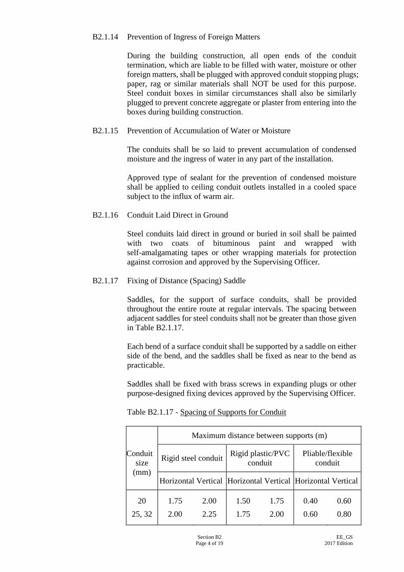
Section B2 Page 4 of 19
EE_GS 2017 Edition
B2.1.14 Prevention of Ingress of Foreign Matters During the building construction, all open ends of the conduit termination, which are liable to be filled with water, moisture or other foreign matters, shall be plugged with approved conduit stopping plugs; paper, rag or similar materials shall NOT be used for this purpose. Steel conduit boxes in similar circumstances shall also be similarly plugged to prevent concrete aggregate or plaster from entering into the boxes during building construction.
B2.1.15 Prevention of Accumulation of Water or Moisture The conduits shall be so laid to prevent accumulation of condensed moisture and the ingress of water in any part of the installation. Approved type of sealant for the prevention of condensed moisture shall be applied to ceiling conduit outlets installed in a cooled space subject to the influx of warm air.
B2.1.16 Conduit Laid Direct in Ground Steel conduits laid direct in ground or buried in soil shall be painted with two coats of bituminous paint and wrapped with self-amalgamating tapes or other wrapping materials for protection against corrosion and approved by the Supervising Officer.
B2.1.17 Fixing of Distance (Spacing) Saddle Saddles, for the support of surface conduits, shall be provided throughout the entire route at regular intervals. The spacing between adjacent saddles for steel conduits shall not be greater than those given in Table B2.1.17. Each bend of a surface conduit shall be supported by a saddle on either side of the bend, and the saddles shall be fixed as near to the bend as practicable. Saddles shall be fixed with brass screws in expanding plugs or other purpose-designed fixing devices approved by the Supervising Officer. Table B2.1.17 - Spacing of Supports for Conduit
Conduit
size (mm)
Maximum distance between supports (m)
Rigid steel conduit Rigid plastic/PVC conduit
Pliable/flexible conduit
Horizontal Vertical Horizontal Vertical Horizontal Vertical
20 1.75 2.00 1.50 1.75 0.40 0.60 25, 32 2.00 2.25 1.75 2.00 0.60 0.80
Section B2 Page 5 of 19
EE_GS 2017 Edition
B2.1.18 Conduit Installed Outdoors or in Damp Situation Where steel conduits are installed outdoors or in damp situations, all conduit fittings and conduit accessories shall not be placed in contact with other metals with which they are liable to set up electrolytic action. In addition, where the conduit installation is subject to weather, the conduit fittings and conduit accessories shall be provided with weatherproof sealant or other materials to ensure that the installation is completely weatherproof.
B2.1.19 Swabbing Out of Conduit Conduits shall be swabbed out and free from moisture before wiring work is to commence. The swabbing operation shall be witnessed by the authorised representative of the Supervising Officer. Only approved draw-in tape or steel wire of appropriate size and absorbent cloth shall be used.
B2.1.20 Fire Barrier Where a conduit passes through fire resistant structural elements, such as walls and floors designated as fire barriers, the opening made shall be sealed according to the appropriate degree of fire resistance of the wall and/or floor. In addition, where a conduit is installed in a channel, duct, ducting, trunking or shaft which pass through such elements, suitable fire-resistant barriers shall also be provided to prevent the spread of fire. Penetration seals for openings where conduit passing through the fire barrier shall be provided in compliance with Code of Practice for Fire Safety in Building.
B2.1.21 Cable Capacity of Conduit The number of cables drawn into a conduit shall be such that no damage will be caused to the cables or to the conduits during their installation. In determining the size of the conduit, the “unit system” method shall be adopted. The sum of all factors for the cables as given in Table B2.1.21-1 shall NOT be greater than the conduit factor as given on Table B2.1.21-2.
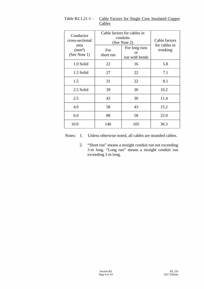
Section B2 Page 6 of 19
EE_GS 2017 Edition
Table B2.1.21-1 - Cable Factors for Single Core Insulated Copper Cables
Conductor cross-sectional
area (mm²)
(See Note 1)
Cable factors for cables in conduits
(See Note 2) Cable factors for cables in
trunking For short run
For long runs or
run with bends 1.0 Solid 22 16 5.8
1.5 Solid 27 22 7.1
1.5 31 22 8.1
2.5 Solid 39 30 10.2
2.5 43 30 11.4
4.0 58 43 15.2
6.0 88 58 22.9
10.0 146 105 36.3 Notes: 1. Unless otherwise noted, all cables are stranded cables.
2. “Short run” means a straight conduit run not exceeding
3 m long. “Long run” means a straight conduit run exceeding 3 m long.
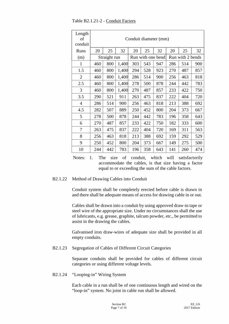
Section B2 Page 7 of 19
EE_GS 2017 Edition
Table B2.1.21-2 - Conduit Factors
Notes: 1. The size of conduit, which will satisfactorily accommodate the cables, is that size having a factor equal to or exceeding the sum of the cable factors.
B2.1.22 Method of Drawing Cables into Conduit
Conduit system shall be completely erected before cable is drawn in and there shall be adequate means of access for drawing cable in or out. Cables shall be drawn into a conduit by using approved draw-in tape or steel wire of the appropriate size. Under no circumstances shall the use of lubricants, e.g. grease, graphite, talcum powder, etc., be permitted to assist in the drawing the cables. Galvanised iron draw-wires of adequate size shall be provided in all empty conduits.
B2.1.23 Segregation of Cables of Different Circuit Categories
Separate conduits shall be provided for cables of different circuit categories or using different voltage levels.
B2.1.24 “Looping-in” Wiring System Each cable in a run shall be of one continuous length and wired on the “loop-in” system. No joint in cable run shall be allowed.
Length of
conduit
Conduit diameter (mm)
Runs 20 25 32 20 25 32 20 25 32 (m) Straight run Run with one bend Run with 2 bends 1 460 800 1,400 303 543 947 286 514 900
1.5 460 800 1,400 294 528 923 270 487 857 2 460 800 1,400 286 514 900 256 463 818
2.5 460 800 1,400 278 500 878 244 442 783 3 460 800 1,400 270 487 857 233 422 750
3.5 290 521 911 263 475 837 222 404 720 4 286 514 900 256 463 818 213 388 692
4.5 282 507 889 250 452 800 204 373 667 5 278 500 878 244 442 783 196 358 643 6 270 487 857 233 422 750 182 333 600 7 263 475 837 222 404 720 169 311 563 8 256 463 818 213 388 692 159 292 529 9 250 452 800 204 373 667 149 275 500 10 244 442 783 196 358 643 141 260 474
Section B2 Page 8 of 19
EE_GS 2017 Edition
B2.1.25 Grouping of Cables in Conduit Conduits running from a distribution board to the final distribution point may each contain all live conductors of a number of final circuits provided that the effective current-carrying capacity of all circuits, upon taking the correction factors into consideration, shall exceed the rating of their respective over-current protection devices and all conditions as stipulated in Clause B2.1.21 above are satisfied. For conduits serving final circuits direct from a distribution board or from an adaptable box used as a final distribution point, each conduit shall contain all live cables of one final circuit only except in the case of lighting final circuit where two circuits with 1.0 mm2 or 1.5 mm2
cables will be permitted in a 20 mm diameter conduit. The neutral cable of a lighting final circuit using single core cables may be routed in the conduit direct to the lighting point without passing through the switch box.
B2.1.26 Termination of Bonding Conductors at Conduit Installation For surface conduit installations, the supplementary bonding conductors shall be terminated at the nearest conduit or conduit box forming an integral part of the conduit installation. For concealed conduit installations, the supplementary bonding conductors shall be terminated at a copper earthing terminal fitted inside a metal box forming an integral part of the conduit installation. The metal conduit box shall be located as near as possible to the bonding position and the exposed part of the supplementary bonding conductor shall be made as short as possible.
B2.2 WIRING IN STEEL TRUNKING SYSTEM
B2.2.1 General Where steel trunking is specified, they shall be installed neatly on the surface of the walls, columns, beams or flushed with floor screeding and shall be installed along a vertical or a horizontal plane. The complete trunking installation shall be mechanically and electrically continuous throughout, and effectively earthed. Wiring system in trunking installation shall consist of non-sheathed copper cables or sheathed copper cables. Cables for 3 phase circuit shall be 450/750 V grade or above. Cables in each final circuit and/or in each sub-main shall be bunched and tied or clipped together. Particular precaution should be taken in situations where high temperature cables may be touched or where they may touch other
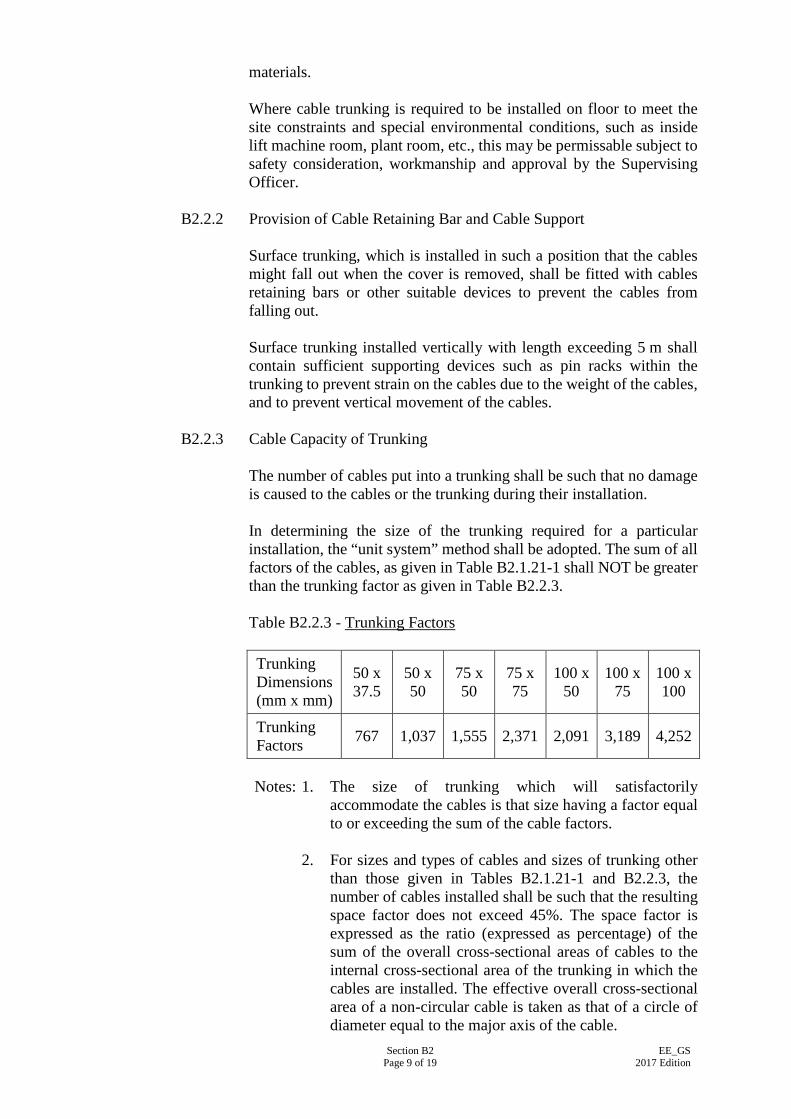
Section B2 Page 9 of 19
EE_GS 2017 Edition
materials. Where cable trunking is required to be installed on floor to meet the site constraints and special environmental conditions, such as inside lift machine room, plant room, etc., this may be permissable subject to safety consideration, workmanship and approval by the Supervising Officer.
B2.2.2 Provision of Cable Retaining Bar and Cable Support Surface trunking, which is installed in such a position that the cables might fall out when the cover is removed, shall be fitted with cables retaining bars or other suitable devices to prevent the cables from falling out. Surface trunking installed vertically with length exceeding 5 m shall contain sufficient supporting devices such as pin racks within the trunking to prevent strain on the cables due to the weight of the cables, and to prevent vertical movement of the cables.
B2.2.3 Cable Capacity of Trunking The number of cables put into a trunking shall be such that no damage is caused to the cables or the trunking during their installation. In determining the size of the trunking required for a particular installation, the “unit system” method shall be adopted. The sum of all factors of the cables, as given in Table B2.1.21-1 shall NOT be greater than the trunking factor as given in Table B2.2.3. Table B2.2.3 - Trunking Factors Trunking Dimensions (mm x mm)
50 x 37.5
50 x 50
75 x 50
75 x 75
100 x 50
100 x 75
100 x 100
Trunking Factors 767 1,037 1,555 2,371 2,091 3,189 4,252
Notes: 1. The size of trunking which will satisfactorily
accommodate the cables is that size having a factor equal to or exceeding the sum of the cable factors.
2. For sizes and types of cables and sizes of trunking other
than those given in Tables B2.1.21-1 and B2.2.3, the number of cables installed shall be such that the resulting space factor does not exceed 45%. The space factor is expressed as the ratio (expressed as percentage) of the sum of the overall cross-sectional areas of cables to the internal cross-sectional area of the trunking in which the cables are installed. The effective overall cross-sectional area of a non-circular cable is taken as that of a circle of diameter equal to the major axis of the cable.
Section B2 Page 10 of 19
EE_GS 2017 Edition
B2.2.4 Correction Factor of Grouping
Where more than one circuit of single-core cables or more than one multi-core cables are enclosed in a common trunking, suitable correction factor for grouping, as recommended by IEC 60364-1:2005/Corr 1:2009 and other associated parts of the standard, shall be applied in determining the size of the cables to be installed. The effective current carrying capacity of all circuits, upon taking the correction factors into consideration, shall exceed the rating of their respective over-current protection devices and all conditions as stipulated in Clause B2.2.3 above are satisfied.
B2.2.5 Segregation of Cables of Different Circuit Categories Where a common trunking is used to accommodate cables for different circuit categories, they shall be effectively segregated by means of partitions or dividers except in the case where trunking is manufactured using two smaller pieces of trunking attached together with a common cover. The partitions or dividers shall be adequately secured to the body of the trunking. For underfloor (duct) trunking, the partitions or dividers shall also be of full depth to provide support and strength to the top surface of the assembly.
B2.2.6 Connection to Equipment Connection between trunking and equipment shall be made by means of a standard flange coupling or an adaptor neck, fabricated or cast. For direct attachment of trunking to equipment, cable entries shall be provided with smooth bore bushes or grommets and the return edge of the lid of the trunking shall be left intact.
B2.2.7 Connection to Distribution Board Where connection is made between trunking and a distribution board, the connectors for cable entry shall be sized to accept all cables from all available circuits including circuits marked as “spare”.
B2.2.8 Fixing of Surface Trunking Individual pieces of trunking shall be independently supported by means of at least two fixed points per piece. On straight runs, supports for trunking shall be fixed at regular intervals with maximum spacing as given in Table B2.2.8. For runs with bends, supports shall be fixed as near to the bend as practicable. Overhead trunking shall be suitably supported by means of mild steel hangers, brackets or other approved means, so that no visible sag is observed when loaded with cables. Unless otherwise specified the hangers or brackets shall be hot-dip galvanised, painted with anti-rust
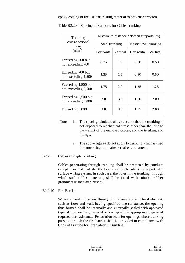
Section B2 Page 11 of 19
EE_GS 2017 Edition
epoxy coating or the use anti-rusting material to prevent corrosion.. Table B2.2.8 - Spacing of Supports for Cable Trunking
Trunking cross-sectional
area (mm2)
Maximum distance between supports (m)
Steel trunking Plastic/PVC trunking
Horizontal Vertical Horizontal Vertical
Exceeding 300 but not exceeding 700 0.75 1.0 0.50 0.50
Exceeding 700 but not exceeding 1,500 1.25 1.5 0.50 0.50
Exceeding 1,500 but not exceeding 2,500 1.75 2.0 1.25 1.25
Exceeding 2,500 but not exceeding 5,000 3.0 3.0 1.50 2.00
Exceeding 5,000 3.0 3.0 1.75 2.00
Notes: 1. The spacing tabulated above assume that the trunking is
not exposed to mechanical stress other than that due to the weight of the enclosed cables, and the trunking and fittings.
2. The above figures do not apply to trunking which is used
for supporting luminaires or other equipment.
B2.2.9 Cables through Trunking Cables penetrating through trunking shall be protected by conduits except insulated and sheathed cables if such cables form part of a surface wiring system. In such case, the holes in the trunking, through which such cables penetrate, shall be fitted with suitable rubber grommets or insulated bushes.
B2.2.10 Fire Barrier Where a trunking passes through a fire resistant structural element, such as floor and wall, having specified fire resistance, the opening thus formed shall be internally and externally sealed with approved type of fire resisting material according to the appropriate degree of required fire resistance. Penetration seals for openings where trunking passing through the fire barrier shall be provided in compliance with Code of Practice for Fire Safety in Building.
Section B2 Page 12 of 19
EE_GS 2017 Edition
B2.2.11 Prevention of Electrolytic Action Where a trunking is installed in a damp situation, or where a trunking is likely to be exposed to weather, the trunking shall be kept away from other metalwork with which electrolytic action is liable to incur.
B2.2.12 Prevention of Ingress of Water Every entry to a trunking shall be so placed as to prevent or to be protected against ingress of water.
B2.3 WIRING IN PLASTIC CONDUIT OR PLASTIC TRUNKING SYSTEM
B2.3.1 General Where wiring in plastic conduits or plastic trunking is specified, they shall comply, where applicable, with the relevant Clauses in B2.1 and B2.2. PVC conduit shall be heavy duty and shall not be used for installation where the ambient temperature exceeds 60°C or below minus 5°C. Conduits may be corrugated, plain or reinforced. Suitable conduit cutter shall be used for cutting rigid PVC conduit.
B2.3.2 Pliable Conduit Pliable conduit shall be used as short as possible. The length of pliable conduit shall be not more than 1 m for general applications or 2 m inside false ceiling and raised floor. Pliable conduit shall not be used in situations where they would be subject to continuous flexing.
B2.3.3 Joint in PVC Conduit Joint in PVC conduit shall be made by means of a solid PVC coupler into which jointing cement shall be applied to the outer surface of the conduit to be joined in turn and then shall be inserted firmly into a coupler and twist a quarter turn to spread cement evenly in order to make the conduit run mechanically continuous.
B2.3.4 Plastic Boxes PVC adaptable boxes and PVC boxes for enclosure of electrical accessories shall be interchangeable with the steel boxes. PVC boxes shall be provided with a brass earthing terminal complete with screw for the connection of circuit protective conductor. They shall not be used for suspension of luminaires or other equipment, where considerable heat will be produced or where the mass of the luminaire or equipment exceeds 3 kg.
Section B2 Page 13 of 19
EE_GS 2017 Edition
Where a concealed conduit system is used in floor slab or wall, a system of PVC rigid conduit fitted with a “screwed to plain PVC converting adaptor” firmly screwed into a deep pattern type cast iron ceiling mounted “BESA” box shall be employed for the suspension of luminaires or other equipment. The system shall also be suitable for the suspended load at the expected working temperature. The threaded portion of the mating converting adaptor shall project to cover the full threaded portion of the “BESA” box and shall be screwed up tightly in order to make the conduit run mechanically continuous. Any exposed threads on the “BESA” box shall be painted with at least two coats of anti-rust paint.
B2.3.5 Termination of PVC Conduit at Casing of Equipment Where a PVC conduit terminates at a casing, a coupler and a PVC bush (i.e. a “plain to screwed” PVC coupler) with a male PVC bush or a “screwed to plain PVC converting adaptor” with a female PVC bush shall be used. In the case of flexible conduit, a rigid PVC glands or a PVC adaptor together with a PVC male bush shall be used. Where PVC adaptor with male bush are used, the male bush shall be screwed into the coupler or adaptor from the inside of the metal casing through a clearance hole drilled in the casing to suit the bush. The bush shall be screwed tightly into the coupler or adaptor so as to grip the casing securely for mechanical continuity. Threads on the male bush shall be long enough to cover the full threaded portion of the coupler. The jointing cement shall be applied on the surface of pliable conduit prior to insertion into the coupler/adaptor and twist.
B2.3.6 Conduit Bend Conduit bend shall be made by the use of purpose made solid elbow or, for PVC conduit not exceeding 25 mm diameter, by bending the conduit itself. Conduit bend shall not be bent more than 90 degrees. The internal radius of the bend shall not be less than 4 times the outside diameter of the conduit. In case of the conduit bend is made by bending the PVC conduit, the conduit bend shall be made by using the appropriate size of conduit bending springs. Conduit shall be fixed in position as soon as possible after bending.
B2.3.7 Allowance for Thermal Expansion Due allowance shall be made for the expansion of PVC tubing at high temperature. Expansion coupling or other fittings shall be installed in a straight run of 8 m or more. Saddles or clips shall be of sliding fit.
B2.3.8 Fixing of Trunking The trunking shall be fixed and supported in the normal way by screws, but the holes in the trunking shall always be made slightly oversize to
Section B2 Page 14 of 19
EE_GS 2017 Edition
allow for the movement of expansion. Washers shall be used under the head of the screw which shall not be over-tightened. The spacing between adjacent supports for trunking shall not be greater than those given in Table B2.2.8.
B2.3.9 Circuit Protective Conductor A PVC insulated cable shall be drawn into the conduit or trunking system to serve as the circuit protective conductor (CPC), the cross-sectional area of which shall comply with the Code of Practice for the Electricity (Wiring) Regulations. CPCs shall also be installed in the steel conduits and trunkings where both PVC and steel conduits are adopted in the conduit system.
B2.3.10 Embedment of Concealed PVC Conduits
Where concealed PVC conduit is specified in the Particular Specification or on the Drawings, concealed PVC conduits installed within concrete or brick walls and floor slabs shall have concrete, cement or plaster cover of thickness not less than 30 mm to prevent penetration of cables inside the conduits by nails, screws or alike. Unless otherwise specified in the Particular Specification or on the Drawings, galvanised steel conduits shall be used instead of PVC conduits in dry wall partition and for all exposed conduits installation including those inside false ceiling and outdoor. Chase for conduit to be concealed in wall, column or beam shall be vertical or horizontal.
B2.4 SURFACE WIRING SYSTEM
B2.4.1 Type of Cable Where surface mounted wiring is specified, sheathed copper cables shall be used for fixed installation. Cables for 3-phase circuit shall be 450/750 V grade or above. Cables shall not be buried in concrete or plaster. Flexible cables or flexible cords shall be used for connection to apparatus, appliances or equipment via an appropriate wiring accessory. Flexible cables or flexible cords shall not be used in fixed installation, except for final connection to a fixed equipment.
B2.4.2 Minimum Size of Live Conductors and CPC Cables shall have CSA not less than 1.0 mm2 for 6 A circuits, 1.5 mm2 for 10 A circuits and 2.5 mm2 for 16 A circuits. Flexible cables and flexible cords shall have CSA not less than 0.75 mm2.
Section B2 Page 15 of 19
EE_GS 2017 Edition
The minimum CSA of a CPC shall be 1.5 mm2 if the CPC is integrated in a cable carrying the associated live conductors. The minimum CSA of a separate CPC shall be 2.5 mm2 if protection against mechanical damage is provided (e.g. sheathed cable), and 4 mm2 if mechanical protection is not provided (e.g. non-sheathed cable). CPC shall be properly sized in accordance with Section B7.
B2.4.3 Identification of Cable Core All conductors shall be coloured as specified in Table C3.7 of this Specification.
B2.4.4 Joint in Cable or Cord Joints in cables or cords shall not be allowed unless approved by the Supervising Officer. In such case, the joints shall be electrically and mechanically sound, be protected against mechanical damage and any vibration liable to occur.
B2.4.5 Installation of Non-flexible Cable
(a) General
All cables shall be run in a vertical or horizontal direction, and shall be secured flat on the surface of walls, columns, partitions or ceilings, etc. throughout the entire route, including at bends. Fixing onto the ceiling shall be avoided unless the cable is required to feed a point on the ceiling. Where required, the cables may be run under floors, between partitions or inside ceiling voids provided that they are enclosed in ducts, conduits or trunking which comply fully with the relevant Clauses in B2.1, B2.2 and B2.3. When cables are routed along or cross steel joints, beams, stanchions, etc. they shall be enclosed in steel or rigid PVC trunking/conduit. Cables shall not be run as a span between beams, trusses, etc., without rigid support throughout their length.
(b) Protection to Cable Susceptible to Damage Cables susceptible to damage shall be protected by means of metal channels. Where protection is required for cables running up a wall from the floor, the metal channel shall be fixed to a minimum height of 1.5 m above finished floor level.
Section B2 Page 16 of 19
EE_GS 2017 Edition
(c) Cable Passing through a Building Structure Where cables pass through a building structure such as a wall or column, the cables shall be drawn through PVC sleeves inserted into the building structure. The size of the PVC sleeves shall be such that the space factor shall not exceed 40%. The gap between the structure and the sleeve and that between the cables and the sleeve shall be completely filled with cement or approved fire-resisting material. Cables crossing an expansion joint shall be formed into a loop such that any movement in the joint shall not stress the cables.
(d) Cable Passing through Metal Work Rubber grommets or insulated bushes shall be used to protect the cables passing through metal part of a distribution board, a luminaire, a metal box or any other metal work.
(e) Segregation from Other Services Cables shall be run at least 150 mm clear of all other non-electrical services.
(f) "Looping-in" Wiring System The cables shall be wired on the "looping-in" system. Cable joints of any type in cable runs shall not be allowed.
(g) Neutral Conductor at Switch Position The neutral conductor of a twin core cable for a lighting final circuit shall be looped through an insulated connector enclosed in the moulded box or pattress accommodating the switch.
(h) Termination of Cable Cable terminated at a moulded box or pattress, a luminaire or other fittings shall have the overall protective sheath carried into the moulded box or pattress, luminaire or other fittings for a minimum of 13 mm. The CPC shall be terminated at the earth terminal provided in the moulded box or pattress housing the wiring accessories. Where it is not required to terminate the CPC in an accessory, it shall not be cut back or removed. Instead, it shall be coiled away from the live terminals or any bare conductors and shall be insulated and sleeved with a green-and-yellow PVC sleeve.
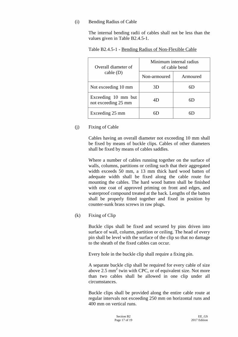
Section B2 Page 17 of 19
EE_GS 2017 Edition
(i) Bending Radius of Cable The internal bending radii of cables shall not be less than the values given in Table B2.4.5-1. Table B2.4.5-1 - Bending Radius of Non-Flexible Cable
Overall diameter of cable (D)
Minimum internal radius of cable bend
Non-armoured Armoured
Not exceeding 10 mm 3D 6D
Exceeding 10 mm but not exceeding 25 mm 4D 6D
Exceeding 25 mm 6D 6D
(j) Fixing of Cable
Cables having an overall diameter not exceeding 10 mm shall be fixed by means of buckle clips. Cables of other diameters shall be fixed by means of cables saddles. Where a number of cables running together on the surface of walls, columns, partitions or ceiling such that their aggregated width exceeds 50 mm, a 13 mm thick hard wood batten of adequate width shall be fixed along the cable route for mounting the cables. The hard wood batten shall be finished with one coat of approved priming on front and edges, and waterproof compound treated at the back. Lengths of the batten shall be properly fitted together and fixed in position by counter-sunk brass screws in raw plugs.
(k) Fixing of Clip Buckle clips shall be fixed and secured by pins driven into surface of wall, column, partition or ceiling. The head of every pin shall be level with the surface of the clip so that no damage to the sheath of the fixed cables can occur. Every hole in the buckle clip shall require a fixing pin. A separate buckle clip shall be required for every cable of size above 2.5 mm2 twin with CPC, or of equivalent size. Not more than two cables shall be allowed in one clip under all circumstances. Buckle clips shall be provided along the entire cable route at regular intervals not exceeding 250 mm on horizontal runs and 400 mm on vertical runs.
Section B2 Page 18 of 19
EE_GS 2017 Edition
A clip shall also be provided at a distance not exceeding 75 mm from a termination and from both sides of a bend.
(l) Fixing of Cable Saddle Cable saddles shall be securely fixed by fixing screws. Saddles shall be provided along the entire cable route at regular intervals. The spacing between adjacent saddles shall not exceed the values given in Table 25(3) of the Code of Practice for the Electricity (Wiring) Regulations. A saddle shall also be provided at a distance not exceeding 150 mm from a termination and form both sides of a bend.
(m) Correction Factor to Current Rating of Cable
Where more than two twin cables are fixed together, or when the cables are installed at or in thermally insulated materials, etc., suitable correction factors, as recommended by IEC 60364-1:2005/Corr 1:2009 and other associated parts of the standard shall be applied in determining the size of the cables to be installed. The effective current carrying capacity of each cable shall be calculated and ensured that it is within the intended operating value of the circuit.
B2.4.6 Installation of Flexible Cable and Flexible Cord (a) Connection to Portable Equipment
Flexible cables or flexible cords for connections to portable appliance or equipment shall have suitable length (preferably 1.5 m to 2 m) to avoid undue risk of mechanical damage.
(b) Connection to Fixed Equipment. Exposed lengths of flexible cable or flexible cord used for final connections to fixed equipment or appliance shall be as short as possible.
(c) Connection to Luminaire Where a flexible cord supports or partly supports a pendant luminaire, the maximum mass acting on the cord shall not exceed 3 kg for flexible cord of 0.75 mm2, and shall not exceed 5 kg for flexible cord of larger conductor CSA.
Section B2 Page 19 of 19
EE_GS 2017 Edition
B2.5 TOOL AND WORKMANSHIP
B2.5.1 Approved Tool Only tools which are proven to be suitable shall be used. Conduit bushes, couplers and similar items shall be tightened with bush spanner or other suitable tools approved by the Supervising Officer. Conduit bends shall be formed on an approved bending machine, and the conduits shall not be flattened or with protective coating damaged at the bends. Suitable cutters shall be used for cutting PVC conduits or trunking.
B2.5.2 Cutting in Metal Work for Conduit or in Trunking
Holes in metal work for the termination of conduits shall be drilled on site with a twist drill of the correct size or by means of an approved hole cutting device. Holes in trunking shall be drilled, punched or cut by ring saw. After cutting, burrs and sharp edges on the metal work or trunking shall be removed to prevent abrasion of cables.
B2.5.3 Making Good of Damaged Coating Where the protective coating on a steel conduit or trunking has been damaged after installation, such surface shall be effectively restored by at least two coats of anti-rust paint or other suitable coating to prevent corrosion.
Section B3 Page 1 of 14
EE_GS 2017 Edition
SECTION B3
INSTALLATION OF POWER CABLES, CABLE TRAYS AND CABLE LADDERS
B3.1 GENERAL
B3.1.1 Scope This Section covers the installation of power cable, which includes those listed in Clause C3.2 of Section C3. It also covers the installation of the associated cabling facilities, including cable trays and cable ladders. Unless otherwise specified elsewhere, all cables shall have copper conductors.
B3.1.2 Electromagnetic Interference To minimise the electromagnetic interference generated from single core cables, the following arrangements shall be adopted: (a) All the single core cables of a circuit shall be of the same
conductor, same cross sectional areas, same type, same construction and from the same manufacturer;
(b) All the single core cables of a circuit shall be of equal length,
and shall follow the same route of installation; (c) The single core cables shall not be able to operate individually;
and (d) The layout of single core cables shall be arranged as shown in
Figure B3.1.2(d) at the end of this Section B3.
B3.2 CABLE MOUNTED ON SURFACE Unless otherwise specified, power cables shall be mounted on the surface of wall or ceiling or other building structure. They shall be cleated in position by approved type cable cleats or cable saddles. Cable cleats or cable saddles shall be provided along the entire cable route according to the Table 25(3) of the Code of Practice for the Electricity (Wiring) Regulations. When specified, power cables may be supported on cable trays or cable ladders. In such cases, the requirements of Clauses B3.9 and B3.10 shall apply. For vertical cable runs exceeding 100 m, tension releasing sections shall be provided in accordance with the recommendation of the cable manufacturer, failing which, a tension releasing section shall be provided for every 100 m vertical run.
Section B3 Page 2 of 14
EE_GS 2017 Edition
B3.3 CABLE LAID IN ENCLOSED TRENCH When power cables are laid in an enclosed trench, the cables shall be installed in accordance with the installation methods 18, 19 and 20 of Appendix 7 of the Code of Practice for the Electricity (Wiring) Regulations. Correction factors shall be applied to the current ratings as indicated in Table A5(6) of the Code of Practice for the Electricity (Wiring) Regulations, where applicable.
B3.4 CABLE ENCLOSED IN DUCT
B3.4.1 General Cables laid in ducts shall be sheathed and armoured. Where mineral insulated cables are specified, they shall be with PVC or XLPE outer cover as specified. Where the ducts are formed from wood, cables shall be held in position by clips, saddles, or approved fixings. The space factor in a cable duct shall not exceed 35%.
B3.4.2 Drawing-in of Cables Prior to the drawing-in of the cables, the cylindrical ducts shall be cleaned with a cylindrical brush of appropriate size. Attachment to facilitate the pulling of cables through a duct shall be made to the cores, insulation, inner and outer sheaths and not to the armour in order to avoid twisting. Attachment to the armour will only be permitted for small cables with the approval of the Supervising Officer. When pulling power cables into small ducts, cable lubricant which should not negatively interact with the cables they lubricate and should not increase the flame spread or decrease the fire resistance properties of the cable may be used for brushing onto the cable surfaces where they enter the duct to reduce friction during pulling. When pulling-in lead-sheathed insulated power cables, the following precautions shall be taken: (a) Maximum stress in sheath - 10,000 kPa (with stocking pulling
grip); (b) Maximum stress in conductors - 70,000 kPa (with pulling eye
attached to conductors); and (c) Maximum pull shall be limited to 220,000 Newtons.
Section B3 Page 3 of 14
EE_GS 2017 Edition
B3.4.3 Internal Barrier In every vertical duct, which is designed as totally enclosed without ventilation, internal barriers shall be provided to prevent the air at the top of the duct from attaining an excessively high temperature. The distance between adjacent barriers shall be the distance between floors. Where the floor to floor distance exceeds 5 m, additional barriers shall be provided at an interval not exceeding 5 m.
B3.4.4 Fire Barrier Where a cable duct passes through fire resistant structural elements, such as floor or wall designated as fire barriers, the opening thus formed shall be sealed with fire resistant materials having the same degree of fire resistance as the structural element. In addition, suitable internal fire barriers shall also be provided. An internal fire barrier may also serve as an internal barrier described in Clause B3.4.3 above. Penetration seals for openings where ducts, cables and the like passing through the fire barrier shall be provided in compliance with Code of Practice for Fire Safety in Building.
B3.4.5 Draw-in Pit Where cables in a duct are inaccessible for the greater part of their length, adequate number of draw-in pits shall be provided at every turning point and at regular intervals of not greater than 15 m. Sufficient room shall be available in the draw-in pits to enable the cables to be manoeuvred without damage. In the case of armoured cables, the draw-in pits shall be concrete or brick lined and shall be fitted with a waterproof heavy cast iron lid. Draw-in pits shall not be filled with sand or other materials. Where a change in direction in a duct occurs, provision shall be made to enable the cables in the duct to have adequate radii of curvature in accordance with the relevant requirements in this Section.
B3.4.6 Segregation of Cables of Different Circuit Categories Separate ducts shall be provided for cables of different circuit categories. However, cables of different categories may be allowed to pass through the same draw-in pit provided that they are properly and appropriately segregated in accordance with the requirements specified in the current Code of Practice for the Electricity (Wiring) Regulations.
B3.4.7 Sealing of Duct Entry to Building After the cables have been installed, both the cables and the exposed duct end shall be sealed to form a gas, water and fire barrier. Open ends of spare ducts shall be closed with tapered hardwood plugs and then sealed similarly.
Section B3 Page 4 of 14
EE_GS 2017 Edition
B3.5 CABLE BURIED DIRECT IN GROUND
B3.5.1 Protection of Cable Power cables buried direct in ground shall be armoured. They shall be buried at a depth of not less than 450 mm and shall be protected by means of approved cable cover tiles. The bottom of the cable trench shall be covered, to a depth not less than the diameter of the largest cable, with a bedding layer of sand or fine soil. On top of the cables, an after layer of sand or fine soil, to a depth of 100 mm, shall again be provided. The sand or fine soil shall not be larger than 13 mm sieve. Particular care shall be taken to ensure that there shall be no pebbles or small stones in the bedding layer or after layer of the fine sand or soil. The cables shall then be covered, throughout the entire route, by approved type cable cover tiles which shall be laid on top of the after layer.
B3.5.2 Cable Marker The route of all power cables buried direct in ground shall be clearly indicated by cable markers laid on the ground. The cable markers shall be engraved with the following wording: "DANGER - ELECTRIC CABLES" Cable markers shall be placed at regular intervals not exceeding 60 m apart and also at positions where the cable route changes direction. At the position of each underground junction box, a cable marker shall also be installed. Such markers shall be engraved, in addition to the wordings mentioned above, the appropriate information, such as "3 way Joint Box".
B3.6 BENDING RADIUS OF CABLE The internal bending radius of every power cable shall not be less than the appropriate values given in Table B2.4.5-1 of this specification.
B3.7 CABLE JOINT AND CABLE TERMINATION
B3.7.1 General Unless otherwise specified in the Particular Specification and approved by the Supervising Officer, cable joint for power cable shall not be used for new electrical installation. Joints and terminations of all power cables shall be made by skilled cable jointers who shall be approved by the Supervising Officer before work commences.
Section B3 Page 5 of 14
EE_GS 2017 Edition
No reduction in the number of strands of a cable core shall be allowed at a cable joint or termination. Ferrules, compression connectors and bare portions of cable core resulting from a jointing or terminating process shall be insulated with an approved type of insulating tape, heat shrinkable tubing or approved means of insulating material after completion of process. Such insulating material shall have equal or better electrical and mechanical properities as those of the original insulation removed, and shall be adhered to the cores, securely and permanently. The final thickness shall be in a smooth contour throughout the whole length. Every compression joint shall be of a type which has been the subject of a test certificate as described in IEC 61238-1:2003 and other associated parts of the standards. When a compression joint is made, the appropriate tools specified by the manufacturer of the joint connectors shall be used.
B3.7.2 Joint Box and Terminating Box Boxes for joints in all power cables shall be of cast-iron, compound filled and of adequate size. The boxes shall be fitted with suitable armouring clamps and glands. The armouring of the cables shall be terminated at the armouring clamps and the inner sheath shall pass through the gland. The box shall be warmed thoroughly before the compound is poured to allow total adhesion between the compound and the box. The compound shall then be allowed to cool and topped up before the box is closed. No air locks shall be formed within the box. Plastic shells fitted with suitably sized armour bond and filled with approved type cold pouring encapsulating compound may be used as alternative for jointing PVC insulated power cables. The complete jointing kit, including plastic shell, compound, insulating tape, etc. shall be from the same proprietary manufacturer who is specialised in manufacturing products for this purpose. The jointing method and procedure as laid down by manufacturer shall be followed strictly.
B3.7.3 Identification at Joint or Termination At each joint or termination, a non-ferrous metallic label shall be fixed to the cable giving the size and identification of the cable, e.g. 50 mm2 4-core XLPE/SWA/PVCS copper cable to "Services Block".
B3.7.4 Earth Continuity across Joint A circuit protective conductor having adequate cross sectional area shall be installed and connected to maintain the effectiveness of the earth continuity across every cable joint.
Section B3 Page 6 of 14
EE_GS 2017 Edition
B3.7.5 Straight-through Joint for Copper Conductors In such joint, the two conductors shall be butted together after the strands have been soldered solid and shall be jointed by means of a weak back ferrule, soldered to the cores. Soldering shall be carried out by pouring tin-man's solder over the cores and weak back ferrule. Under no circumstances shall direct flame from a blow lamp be used for soldering. As an alternative, conductors may be jointed by approved type compression connectors using the appropriate tools and connectors.
B3.7.6 Tee-joint for Copper Conductor When two cables with copper conductors are tee-jointed, the branch conductor shall be connected to the main conductor by means of claw type or weak back ferrules. The strands in both branch and main conductors are to be sweated solid before sweating to the ferrule. Soldering shall be carried out as detailed in Clause B3.7.5 above. As an alternative, conductors may be jointed by approved type compression connectors using the appropriate tools and connectors.
B3.7.7 Joint for Aluminium Cables (a) Soldered Joint
Prior to making a soldered joint, each conductor shall be cleaned by means of steel wool or similar abrasive and then tinned by pouring solder, specially made for use with aluminium, over the cores. Both cores shall then be inserted in a weak-backed aluminium ferrule and butted together. The ferrule shall then be closed. Soldering shall be completed by pouring the solder over the ferrule, after applying a layer of flux recommended by the cable manufacturer for this purpose.
(b) Compression Joint
Alternatively, the aluminium cores may be jointed by means of an approved type compression joint. A compression joint shall be made by inserting the aluminium cores to be jointed into the opposite ends of an aluminium compression jointing tube, which shall have the correct size for the conductors. The tube shall then be compressed onto the cores by means of a compressing tool. The tool used and the working procedure adopted shall be as recommended by the cable manufacturer.
B3.7.8 Termination of PVC-insulated or XLPE-insulated Cable with Copper
Conductors PVC-insulated or XLPE-insulated cables shall be terminated in a gland fitted with an armour clamp. Provision shall be arranged to enable a
Section B3 Page 7 of 14
EE_GS 2017 Edition
watertight seal to be made between the gland and inner sheath. The gland body shall be provided with an internal conical seating to receive the armour clamping cone and a clamping nut which shall secure the armour clamping cone firmly to the armour wires ensuring that the armour wires are tightly clamped between the armour cone and conical armour seating. The spigot on the gland body shall be threaded to suit standard conduit accessories. A shroud of PVC or alternative approved materials shall be fitted to cover the body of the gland and the exposed armour wires. The copper cores shall be soldered to the cable lugs or cable sockets by the "damp sweat" method as described in Clause B3.7.5 above. As an alternative, conductors may be terminated by approved type compression terminations using the appropriate tools and terminations.
B3.7.9 Termination of PVC-insulated or XLPE-insulated Cable with Aluminium Conductors Terminating gland and armour clamp for power cables with aluminium conductors shall be made from aluminium. Termination of gland and clamping of armour shall be the same as for copper core armoured cables as described in Clause B3.7.8 above. Cores shall be terminated in a hot tinned brass or copper lug, which should be shaped in a vice or by means of a hammer to suit the sector shape of the conductor. The core shall be tinned, and then soldered into the lug. As an alternative to terminating cores in a tinned brass or copper lug, a compression termination may be used. In such case, the cores shall be inserted into the sleeve of an aluminium compression type cable lug. The sleeve shall then be compressed onto the cores by means of a compressing tool. The tool used and the working procedure adopted shall be as recommended by the cable manufacturer. Prior to connection to the terminal, the cable lug shall be painted with an anti-oxidising paste. The anti-oxidising paste shall be suitable for preventing the creation of electrolytic action due to contact between the aluminium lug and copper or brass terminal, for an indefinite period. Alternatively, copper/aluminium bimetal cable lugs may be accepted.
B3.7.10 Use of Heat Shrinkable Tubing All heat shrinkable tubing and accessories used for cable joints or termincations shall be suitable for use with the type and construction of cable to be jointed or terminated. The heat shrinkable materials shall have electrical and mechanical properties equal to or better than those of the cable insulation and sheath, where applicable. After the application of the heat, the heat shrinkable materials shall seal the interfaces between the heat
Section B3 Page 8 of 14
EE_GS 2017 Edition
shrinkable materials or between the heat shrinkable materials and the cable surfaces. Whenever heat shrinkable tubing and accessories are used, the complete kit shall be from the same proprietary manufacturer who is specialised in manufacturing products for this purpose. The method and procedures adopted shall be strictly as those laid down by the manufacturer.
B3.7.11 Other Methods of Joint and Termination Methods for jointing or terminating a power cable, other than those specified in this Sub-section, will not be precluded provided: (a) that the method used shall be proven to be capable of affording
the degree of safety, reliability, durability and efficiency not less than that achieved by those specified in this Sub-section,
(b) that the method used shall satisfy the requirements of IEC
60364-1:2005/Corr 1:2009 and other associated parts of the standard and other relevant Standards, and
(c) that prior agreement of the Supervising Officer has been
obtained.
B3.8 SPECIAL REQUIREMENTS FOR MINERAL INSULATED CABLES
B3.8.1 Cable Route Mineral-insulated cables shall be run neatly on the surface of the walls, columns, beams or ceilings in a vertical or horizontal direction, and at least 150 mm clear of all plumbing and mechanical services. The use of conduit and/or cable trunking to enclose such cables shall be kept to the minimum.
B3.8.2 Cable Support Mineral-insulated cables shall be adequately supported by saddles which shall be of the same manufacturer as the cables. Saddles shall be provided throughout the entire cable route at regular intervals. The spacing between adjacent saddles shall not exceed the values given Table B3.8.2. Saddles shall also be provided at a distance not exceeding 150 mm away from a termination and from both sides of a bend.
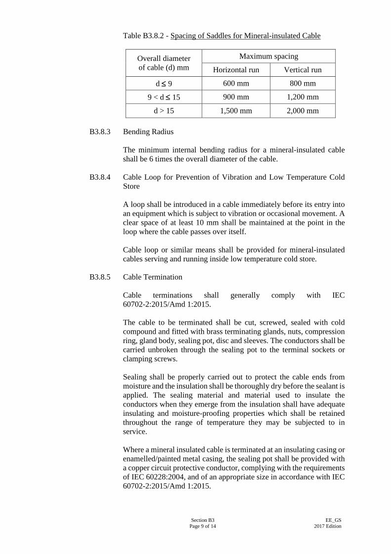
Section B3 Page 9 of 14
EE_GS 2017 Edition
Table B3.8.2 - Spacing of Saddles for Mineral-insulated Cable
Overall diameter of cable (d) mm
Maximum spacing
Horizontal run Vertical run
d ≤ 9 600 mm 800 mm
9 < d ≤ 15 900 mm 1,200 mm
d > 15 1,500 mm 2,000 mm
B3.8.3 Bending Radius The minimum internal bending radius for a mineral-insulated cable shall be 6 times the overall diameter of the cable.
B3.8.4 Cable Loop for Prevention of Vibration and Low Temperature Cold Store A loop shall be introduced in a cable immediately before its entry into an equipment which is subject to vibration or occasional movement. A clear space of at least 10 mm shall be maintained at the point in the loop where the cable passes over itself. Cable loop or similar means shall be provided for mineral-insulated cables serving and running inside low temperature cold store.
B3.8.5 Cable Termination
Cable terminations shall generally comply with IEC 60702-2:2015/Amd 1:2015. The cable to be terminated shall be cut, screwed, sealed with cold compound and fitted with brass terminating glands, nuts, compression ring, gland body, sealing pot, disc and sleeves. The conductors shall be carried unbroken through the sealing pot to the terminal sockets or clamping screws. Sealing shall be properly carried out to protect the cable ends from moisture and the insulation shall be thoroughly dry before the sealant is applied. The sealing material and material used to insulate the conductors when they emerge from the insulation shall have adequate insulating and moisture-proofing properties which shall be retained throughout the range of temperature they may be subjected to in service. Where a mineral insulated cable is terminated at an insulating casing or enamelled/painted metal casing, the sealing pot shall be provided with a copper circuit protective conductor, complying with the requirements of IEC 60228:2004, and of an appropriate size in accordance with IEC 60702-2:2015/Amd 1:2015.
Section B3 Page 10 of 14
EE_GS 2017 Edition
Where more than one cable terminates at a galvanised or zinc coated enclosure, the gland plate shall be of brass or insulating materials. PVC shrouded terminating glands shall be used when the cables are fitted with PVC outer covering. Only tools recommended by the manufacturer of the cables shall be used and the manufacturer's recommended methods of cable termination shall be adopted in all cases.
B3.8.6 Insulation Resistance The insulation resistance between the cores and between each core and the sheath shall be measured before the cable end is sealed. The measured resistance shall be infinity on a 500 V insulation resistance tester. If the reading is less than infinity, the cable shall be heated by means of a blow lamp or similar device so that moisture is driven out to the open end of the cable. Heating shall be continued until the measured insulation resistance reaches infinity, and sealing shall be applied immediately. The insulation resistance shall be measured again when the cable end has been sealed to ensure infinite resistance. For mineral-insulated cable with outer covering, adequate length of the outer covering shall be cut out in the event of low insulation resistance to allow dehydration by the application of blowlamp as described above. After the process is completed, the section of outer covering shall be re-installed as specified.
B3.8.7 Bonding of Cable Sheath to Metalwork
Where a mineral-insulated cable passes through or makes contact with any metal, the metal and cable sheath shall be effectively bonded together.
B3.8.8 Laying of Single-core Cables Single-core mineral-insulated cables running together shall be laid with the cable sheaths in contact. Mineral-insulated cables for 3-phase circuits shall be laid in trefoil formation. Where cables used are rated at 100 A or above, gland plates of apparatus shall be of brass.
B3.8.9 Protection from Mechanical Damage Mineral-insulated (MI) cables shall be protected by steel sleeves where they are exposed in vulnerable positions (e.g. passing through floors, ceilings and walls). Insert material between copper oversheath of cable and steel sleeve shall be dielectrically isolated form one another to prevent galvanic action. The openings or holes through which the cables pass shall be made good with cement or other non-combustible material.
Section B3 Page 11 of 14
EE_GS 2017 Edition
B3.9 INSTALLATION OF PERFORATED CABLE TRAYS
B3.9.1 Connection between Adjacent Lengths of Tray Connections between adjacent lengths of tray, tee or bend pieces, shall be made by butt joints and fixed by mushroom-head steel roofing bolts and nuts complying with BS 1494-1:1964. The connection shall be mechanically strong so that no relative movement between the two lengths can occur.
B3.9.2 Cutting of Tray Cable trays shall be cut along a line of plain metal only, i.e. they shall not be cut through the perforation. All cut edges of the galvanised cable tray shall be prepared and treated with a cold galvanised paint.
B3.9.3 Hole in Tray
Holes cut in a cable tray for the passage of cable shall be provided with grommets. Alternatively, they shall be bushed or lined.
B3.9.4 Fixing of Tray
The cable tray except those of short run less than 300 mm long where at least 1 set of hanger or bracket is required, shall be supported by at least 2 sets of hangers or brackets of adequate mechanical strength securely fixed to the walls, ceiling or other structure. Unless otherwise specified the hangers or brackets shall be hot-dip galvanised, painted with anti-rust epoxy coating or the use anti-rusting material to prevent corrosion . Fixings for cable trays shall be disposed at regular intervals not exceeding 1.2 m for straight run and at a distance not exceeding 225 mm on both sides from a bend or intersection. A minimum clear space of 20 mm shall be left behind all cable trays.
B3.9.5 Fixing of Cable on Tray
Saddles for securing multi-core cables to the cable tray shall be made from PVC covered metal strip, and shall be shaped to the form of the cables to be secured. The saddles shall be fixed to the cable tray by means of corrosion resistant cheese-headed screws and nuts. The shanks of the screws shall not protrude beyond the nuts by more than three threads. Where saddles exceed 150 mm in length, intermediate fixings shall be provided such that the maximum spacing between screws shall not exceed 150 mm. Single-core cables shall be secured to the cable tray by clamps made of wood or other non-ferrous materials specially designed to suit the dimension of the cables. The clamp shall be secured to the cable tray by means of bolts, washers and nuts.
Section B3 Page 12 of 14
EE_GS 2017 Edition
Cable saddles or cable clamps shall be provided along the entire cable route with their spacing in accordance with the manufacturer’s recommendation.
B3.10 INSTALLATION OF WIRE MESH CABLE TRAYS
B3.10.1 General Unless otherwise specified, the installation of wire mesh cable tray system shall be generally in accordance with the manufacturer’s installation instruction.
B3.10.2 Supports The wire mesh cable tray except those of short run less than 300 mm long where at least 1 set of hanger or bracket is required, shall be supported by at least 2 sets of hangers or brackets. Supports shall be properly spaced at distance not exceeding 1,500 mm for straight run to satisfactorily support the weight of the tray and cables.
B3.10.3 Bends In general, large radius bend shall be used for the wire mesh cable tray system. 90∘ bend shall not be installed unless otherwise approved by the Supervising Officer.
B3.10.4 Earthing The wire mesh cable tray shall be bonded and earthed throughout in order to maintain the earth continuity for equipotential bonding.
B3.10.5 Safety Working Load The weight of cables per span of the wire mesh cable tray shall be uniformly distributed and shall not exceed the maximum working load specified by the manufacturer.
B3.11 INSTALLATION OF CABLE LADDER
B3.11.1 Dropout Plate for Cable Exit Dropout plate of width same as the cable ladder shall be provided to support the cables locally as they exit a ladder down between the rungs.
B3.11.2 Flexible (Expansion) Couplers across Building Expansion Joint The cable ladders shall be jointed by flexible (expansion) couplers across the expansion joints of the building structure. The selection and installation details of such flexible couplers shall be recommended by the manufacturer and submitted to the Supervising Officer for
Section B3 Page 13 of 14
EE_GS 2017 Edition
acceptance. Rigid fitting across the expansion joints shall not be allowed.
B3.11.3 Ladder Covers Unless otherwise specified, proprietary ladder covers (ventilated or closed as specified) shall be fixed onto the cable ladder following the installation details recommended by the manufacturer.
B3.11.4 End Connectors The end of a run of cable ladder shall be fixed to the wall or slab with proprietary end connectors. If it is far from the wall or slab, a proprietary “stop end” connector shall be fixed to the end of a cable ladder run in order to give a neater appearance. Installation details shall follow the manufacturer’s recommendation.
B3.11.5 Earthing
The cable ladders shall be bonded and earthed throughout. Across all joints of the cable ladder, copper connectors shall be fixed onto the cable ladder in order to maintain the earth continuity. Factory-made attachment points shall be provided near the joints for fixing the earth continuity connectors. The length of the copper connectors shall be slightly longer than the length between the two attachment points to allow for movement at the joints due to expansion or some other reasons.
B3.11.6 Minimum Inside Radius of All Bends The inside radius of all bends of the cable ladder system shall not be less than 300 mm.
B3.11.7 Supports The cable ladder except those of short run less than 300 mm long where at least 1 set of hanger or bracket is required, shall be supported by at least 2 sets of hangers or brackets. Supports shall be properly spaced at distance not exceeding 1,500 mm for straight run to satisfactorily support the weight of the ladder and cables. Unless otherwise specified the hangers or brackets shall be hot-dip galvanised, painted with anti-rust epoxy coating or the use anti-rusting material to prevent corrosion. They shall also be provided at a distance not exceeding 300 mm on every side from a bend or intersection.
B3.11.8 Safety Working Load The weight of cables per span of the cable ladder shall be uniformly distributed and shall not exceed the maximum working load specified by the manufacturer.
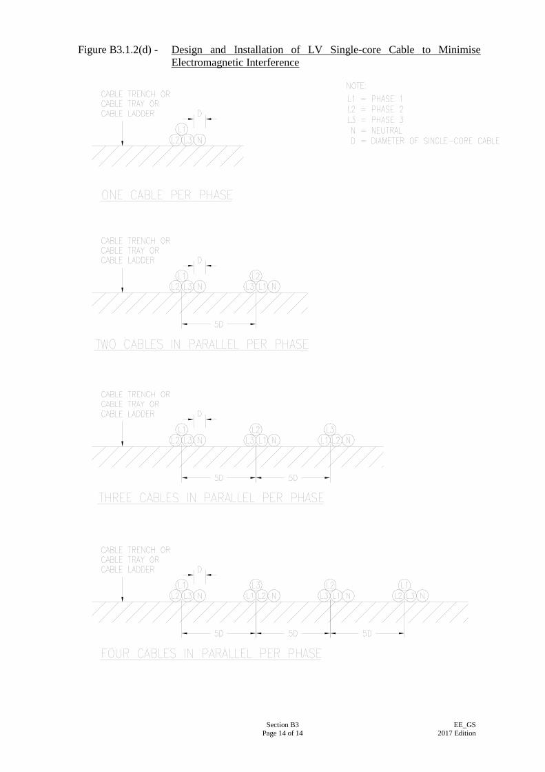
Section B3 Page 14 of 14
EE_GS 2017 Edition
Figure B3.1.2(d) - Design and Installation of LV Single-core Cable to Minimise Electromagnetic Interference
Section B4 Page 1 of 4
EE_GS 2017 Edition
SECTION B4
INSTALLATION OF GENERAL LIGHTING AND POWER
B4.1 INSTALLATION OF LIGHTING SYSTEM AND LUMINAIRES
B4.1.1 Pendant Tube pendant shall comprise a dome cover and a biscuit ring and a piece of screwed steel conduit of suitable length to give the required mounting height of the luminaire. Plain pendant shall comprise a ceiling rose and a cord-grip lampholder connected by a flexible cord having a suitable length to give the required mounting height of the lamp shade.
B4.1.2 Luminaire Mounted on Pattress When a luminaire is not provided with facility for a surface cable entry, the luminaire shall be mounted on pattress. The cable shall then enter the luminaire from the rear through a slot and a hole formed in the pattress.
B4.1.3 Ceiling Rose Ceiling rose shall not be used for the attachment of more than one outgoing flexible cord or cable unless it is specially designed for multiple pendants.
B4.1.4 Painting Unless otherwise specified, lighting equipment and luminaires other than those indicated to be self-finished such as stainless steel, anodized aluminium, etc, shall have factory-finished. Metal parts such as cover plates for adaptable boxes, blanking plate for any boxes and surface conduit, etc. shall be painted white or a suitable colour to match the interior finish of a particular location.
B4.1.5 Special Requirements for Outdoor Luminaires Outdoor luminaires shall be able to withstand the weather. Metal work should be protected against corrosion, and parts which have to be removed for access to the interior shall be provided with proper gaskets to restrict the entrance of moisture and dirt. Mounting brackets shall be heavily galvanised and stainless steel or galvanised bolts and nuts shall be used. The adjustment bolts and nuts of a luminaire which is mounted on high level shall be captive to prevent accidental loss during servicing. Safety chains shall be provided to hold the luminaire from falling. A

Section B4 Page 2 of 4
EE_GS 2017 Edition
luminaire installed in a location within hand reach shall be of robust construct, fitted with an impact-resistant transparent or diffusing front panel, and shall have secret key fixings for the panel to the body of the luminaire. Where necessary, wire guards shall be fitted over the front panel to give extra protection. Cables within the outdoor luminaire shall be such a type that it can sustain the lamp operation at a high ambient temperature due to the waterproof/airtight natures of the luminaire design. Heat resistant cable is considered as an acceptable mean of internal cable for outdoor luminaire. Any other cable type with appropriate type test certification demonstrating satisfactory use for outdoor luminaire shall be submitted for approval by the Supervising Officer. Heat resistant sleeve shall be used for external cable entering the luninaire for wiring connection as far as practicable. Where installation of heat resistant sleeve is found impracticable due to environmental constraints, alternative mean avoiding cause of adverse effect as a result of high internal operating temperature shall be submitted for Supervising Officer’s approval. Where the heat resistant sleeves is required, the sleeves within the luminaire shall be extended to a distance of 150 mm outside the luminiare.
B4.2 INSTALLATION OF WIRING ACCESSORIES Wiring accessories, including lighting switches, socket outlets and domestic type switches for electrical appliances, shall be designed for flush mounting. Where surface wiring installation is specified, wiring accessories shall be fixed onto moulded boxes or pattresses. In conduit installation, they shall be fixed onto moulded, galvanised steel or cast iron boxes. Where a waterproof or flameproof configuration is required, wiring accessories shall be mounted as the particular circumstances demand. The front plate of a switch or socket outlet shall be labelled in accordance with Clause B1.2.
B4.3 INSTALLATION OF DOMESTIC SWITCHES
B4.3.1 General Switch for domestic and similar purposes shall be mounted at a height of 1350 mm above finished floor level unless otherwise specified.
B4.3.2 Lighting Switch
When lighting switches are mounted adjacent to one another, they shall be grouped in a single enclosure (single or multi-gang box) and shall
Section B4 Page 3 of 4
EE_GS 2017 Edition
share a common switch plate, subject to a maximum of three lighting switches per single-gang plate. Lighting switches installed adjacent to a door shall be located on the handle side of the door, and shall be as near to the door as practicable.
B4.3.3 Time Switch Time switch shall be housed in a factory or purpose made metal enclosure provided with a removal cover of durable clear plastic material.
B4.3.4 Application in Bathroom No switch shall be installed inside a toilet or a room containing a fixed bath or shower. All control switches shall be located immediately outside the room. This restriction does not apply to insulating cord switches, remotely operated switches using mechanical actuators with linkage incorporating insulating components, switched supplied from Separated Extra Low Voltage (SELV) and shaver units.
B4.4 INSTALLATION OF SOCKET OUTLETS
B4.4.1 General Socket outlet intended for supplying a fixed or stationary appliance shall be located as near as possible to the appliance. Socket outlet shall be mounted at a height of 1350 mm above finished floor level in kitchens, sculleries, ironing rooms and the like. In other locations, they shall be mounted at 300 mm from finished floor level, 75 mm from surface top measured from bottom of socket outlet or as specified.
B4.4.2 Shaver Supply Unit The complete unit shall be enclosed in a galvanised metal box for flush mounting, or a galvanised cast iron or plastic surface box for surface mounting.
B4.4.3 Socket Outlet at Hazardous Area The installation of socket outlets in hazardous areas should be avoided as far as possible. Where it is absolutely essential to install a socket outlet in such area, the socket outlet shall comply with IEC 60079-0:2011 and other associated parts of the standard and shall be controlled by a sparkless switch. The socket outlet shall be interlocked with the plug so that removal or insertion shall not be possible unless the controlling switch is in the OFF position. The plug shall have
Section B4 Page 4 of 4
EE_GS 2017 Edition
shrouded pins and the design of the pin contacts shall be such as to guard against development of hot spots or sparking. Requirements for wiring installation in hazardous areas are specified in Clause B8.3.
B4.4.4 Socket Outlet of Surface Conduit System In plant room, switch room or similar area where surface conduits are installed, socket outlets shall be metalclad or bronze front plate.
B4.4.5 Socket Outlet for Different Voltage System Socket outlet and plug for one voltage system shall not be interchangeable with those for use at other voltage and/or frequency systems in the same installation.
B4.4.6 Application in Bathroom Shaver supply units complying with IEC 61558-2-5:2010 can be installed inside a room containing a fixed bath or shower and inside a toilet. Socket outlets inside such a room, if so required under the Contract, shall be installed in accordance with requirements of Code 26A(3)(j) of the Code of Practice for Electricity (Wiring) Regulations.
B4.5 INSTALLATION OF MEASURING INSTRUMENT
B4.5.1 Mounting of Current Transformers Associated with Watt-hour Meter Current transformers, if required to be associated with a watt-hour meter, may be mounted inside the meter chamber, or in a separate current transformer chamber, as dictated by the circumstances of each particular job. When current transformers are mounted in the meter chamber, separate partitioned compartments with separate front access covers for the current transformers and meters respectively shall be provided. Suitable engraved labels shall be fixed on the covers to identify the installed equipment therein.
B4.5.2 Identification of Instrument Each measuring instrument shall be identified by means of a label fitted under the associated instrument. This label shall denote the function of the circuit connected to the meter.
B4.5.3 Mounting Position of Selector Switch
Selector switch for ammeter or voltmeter shall be mounted immediately below the meter with which it is associated.
Section B5 Page 1 of 6
EE_GS 2017 Edition
SECTION B5
INSTALLATION OF DOMESTIC APPLIANCES
B5.1 GENERAL
B5.1.1 Connection to Appliances Domestic appliances shall each be connected to the electrical supply through a suitable wiring accessory and a suitable length (preferably 1.5 m to 2 m) of flexible cable or PVC insulated cables enclosed in a flexible conduit. For portable appliance, plug and socket shall be used. For fixed appliances, the wiring accessories shall be opened or removed only by means of a tool. Wiring accessories shall meet the requirements of Section C4 and shall be installed as near as practicable to the appliances to be connected. Fuse-links shall comply with IEC 60127-1:2015 and the other associated Parts of the Standard and shall have current ratings suitable for the appliances to be controlled. Flexible cables for final connection to domestic appliances shall be white in colour unless otherwise specified, and shall be circular, sheathed, twin core with circuit protective conductor (CPC) to IEC 60189-1:2007 and the associated parts of the standard; and IEC 60227-1:2007 and the associated parts of the standard (PVC-insulated) or to IEC 60245-1:2008 and the associated parts of the standard (rubber-insulated), all with copper conductors. Twin core cables without earth wire are only allowed for double insulated appliances classified as Class II appliances under IEC 61140:2016. The cores of the flexible cables shall have identification colours in accordance with Section Table C3.7 in Section C3.
B5.1.2 (NOT USED)
B5.1.3 Engraving for Identification The front plate of every switched socket outlet, fused connection unit or control switch feeding a fixed domestic appliance shall be engraved in accordance with Sub-section B1.2 to indicate correctly its function.
B5.1.4 Earthing of Appliance All domestic appliances except Class II equipment to IEC 61140:2016 shall be effectively earthed to the main earth via a circuit protective conductor. Where the cables for final connection to a fixed appliance is enclosed in a flexible conduit, effective earthing shall be achieved by means of a separate circuit protective conductor drawn into the flexible conduit.
Section B5 Page 2 of 6
EE_GS 2017 Edition
B5.1.5 Appliances Requiring Exclusive Circuit The following types of domestic appliances shall be supplied from an exclusive final circuit: (a) Household electric cooker
(b) Water heater other than oversink water heater
(c) Water boiler
(d) Room cooler
(e) Appliance having a normal power rating of 3 kW or above
B5.2 CEILING FAN AND CEILING-MOUNTED ROTARY FAN
B5.2.1 Method of Supply Supply to a ceiling fan or a ceiling mounted rotary fan shall be by means of a 2 A fused connection unit with earthing facilities and controlled by a 5-20 A D.P. switch with pilot light for maintenance purpose. The fuse connection unit shall be suitable for mounting either on a conduit box to IEC 60670-1:2015 and the associated parts of the standard for concealed conduit installation or on a moulded box or plastic pattress to IEC 60670-1:2015 and the associated parts of the standard for surface conduit and surface wiring installation.
B5.2.2 Fixing of Fan Every ceiling fan shall be suspended from a substantial hook fixed securely to the ceiling structure. Rotary fans shall be fixed direct to the ceiling structure.
B5.2.3 Fan Regulator
Fan regulators shall each be controlled by a 5-20 A D.P. switch with pilot light and shall be fixed on the surface of walls. In a concealed conduit installation, the fan regulator shall be mounted on a back-plate over a recessed 35 mm deep box to IEC 60670-1:2015 where the conduit shall be terminated. The back-plate shall be made of galvanised sheet steel of 3 mm thick with suitable grommeted hole for cable entry. In a surface conduit installation, the fan regulator shall be mounted on a special fabricated box of 1.5 mm thick galvanised sheet steel and having the same size as the regulator or proprietary fabricated box by the fan manufacturer. The conduit shall be terminated at this specially made surface mounted box which the cables shall enter the fan regulator.
Section B5 Page 3 of 6
EE_GS 2017 Edition
In a surface wiring installation, the fan regulator shall be mounted on a wooden block. Groove shall be formed at the back surface of the wooden block to suit the cables, and holes shall be drilled to enable the cables to enter the fan regulator from the rear.
B5.3 WALL-MOUNTED FAN Supply to a wall mounted fan shall be by means of a 2 A fused connection unit and shall be controlled by a 5-20 A D.P. switch with pilot light. Wall mounted fans shall each be fixed by means of wall mounting bracket supplied with the fan or sit on a mounting bracket or battern made of teak wood or other material approved by the Supervising Officer.
B5.4 EXHAUST FAN
B5.4.1 Fixing of Fan Exhaust fans shall each be installed on the structural opening by means of a steel mounting plate. Where an exhaust fan is intended to draw exhausted air through a fume cupboard, the fan shall be ducted to the fume cupboard by means of a pipe made of low smoke emission and halogen free PVC of suitable size and length.
B5.4.2 Method of Supply Supply to a domestic type/fume cupboard exhaust fan shall be by means of a 2 A fused connection unit similar to that for a ceiling fan, and shall be controlled by a 5-20 A D.P. switch with pilot light. Supply to an industrial type exhaust fan shall be by means of a fused connection unit with suitably sized fuse and shall be controlled by a 20 A D.P. switch with pilot light.
B5.5 ELECTRIC FIRE OR HEATER
B5.5.1 Wall-mounted Radiator Supply to wall-mounted radiators shall be obtained through a fused connection unit with suitably sized fuse and shall be controlled by a 20 A D.P. switch with pilot light.
B5.5.2 Panel Fire Panel fires rated at 3 kW or less shall each be supplied and controlled by a 15 A 3-pin switched socket outlet with pilot light. The switched socket outlet shall be installed at a height of 300 mm above finished floor level unless otherwise specified.
Section B5 Page 4 of 6
EE_GS 2017 Edition
B5.5.3 Tubular Heater
Tubular heaters shall be supplied and controlled by a 13 A 3-pin switched socket outlet with pilot light. A wire guard complete with end plates made of hot-dip galvanised steel shall be provided to prevent falling fabric from contact with the heater tube as to create a fire risk.
B5.6 WATER HEATER AND WATER BOILER
B5.6.1 Oversink Water Heater Supply to an oversink water heater shall be by means of a 13 A fused connection unit controlled by a 20 A D.P. switch with pilot light at a distance not less than 2 m from any water taps. The front plate of the fused connection unit shall have an outlet hole and the necessary cord-grip for the flexible cable. In a surface wiring installation, the fused connection unit and the 20 A D.P. switch shall each be mounted on a moulded box or plastic pattress to IEC 60670-1:2015 and the associated parts of the standard.
B5.6.2 Other Type of Water Heater Supply to a domestic thermal storage or instantaneous water heater shall be connected to an individual final circuit. Single phase water heater shall be controlled by a double-pole switch of adequate rating and with pilot light. Three phase water heater shall either be controlled by a 4-pole switch of adequate rating and with pilot light or by a 20 A double-pole switch with pilot light through a 4-pole contactor of adequate rating. In a concealed or surface conduit installation, the PVC insulated cables shall be enclosed in a conduit from the control switch to a standard circular conduit box fitted with a dome cover and then through a flexible conduit from the dome cover to the water heater. The dome cover and the conduit shall be fixed as near to the water heater as practicable. In a surface wiring installation, the control switch shall be mounted on a moulded box or plastic pattress. Final connection to the water heater shall be taken from the control switch via a flexible cable, twin with CPC. The control switch shall be fixed as near to the water heater as practicable.
B5.6.3 Water Boiler The installation of a water boiler shall be similar to that for water heater. The control switch shall be a double-pole switch of 30 A rating and with pilot light.
Section B5 Page 5 of 6
EE_GS 2017 Edition
B5.7 TEA URN Tea urns having a rating of 3 kW or less shall be supplied and controlled by a 15 A 3-pin switched socket outlet with pilot light, while those of ratings higher than 3 kW is to be supplied and controlled by fused connection unit completed with separate DP control switch with pilot light. The switched socket outlet shall be fixed at a height of 1350 mm above finished floor level unless otherwise specified.
B5.8 HOUSEHOLD ELECTRIC COOKER Supply to a household electric cooker shall be controlled by a cooker control unit of rating not less than 45 A unless otherwise specified. The control unit shall be installed at a height of 1350 mm above finished floor level. In a concealed or surface conduit installation, the PVC insulated cables from the control unit shall be enclosed in a conduit and terminated at an insulated terminal block inside a 47 mm deep conduit box to IEC 60670-1:2015 and the associated parts of the standard. The PVC insulated cables shall then be changed into PVC insulated and sheathed cable twin core with CPC before connecting to the cooker. The insulated terminal block shall be mounted on the wall at 300 mm above finished floor level. The PVC insulated and sheathed cable twin core with CPC shall be 1.5 m to 2 m long to allow the cooker to be moved for cleaning purpose. In a surface wiring installation, PVC insulated and sheathed cable twin with CPC shall be used throughout.
B5.9 HAND/FACE DRYER The supply to an electric hand/face dryer shall be by means of a fused connection unit complete with an integrated 20 A D.P. switch and pilot light. The front plate of the fused connection unit shall have an outlet hole and the necessary cord-grip for the flexible cable. Hand/face dryer shall be installed at such a height so as to allow the nozzle to be 1150 mm above finished floor level in male toilet and 1,100 mm in female toilet.
B5.10 ROOM COOLER
B5.10.1 Method of Supply Supply to a room cooler shall be by means of a connection unit and a control switch, both of which shall have a current capacity of not less than the rated value of the room cooler. The control switch shall be D.P. with pilot light, installed at a height of 1,350 mm above the finished floor level.
B5.10.2 Position of Connection Unit
The connection unit shall be installed adjacent to the room cooler and
Section B5 Page 6 of 6
EE_GS 2017 Edition
shall be on the same side of the room cooler as where the flexible cable enters the room cooler. In case it is not possible to ascertain where the flexible cable enters the room cooler, the connection unit shall be installed on the left side of the room cooler, as viewed from the front.
B5.11 REFRIGERATOR Supply to a refrigerator shall be by means of a 13 A switched socket with pilot light. For general purpose, the socket shall be mounted at a height of 1350 mm above finished floor level.
Section B6 Page 1 of 5
EE_GS 2017 Edition
SECTION B6
INSTALLATION OF BUSBAR TRUNKING SYSTEM
B6.1 GENERAL Busbar trunking including accessories shall be tailor-made to suit the actual site measurements, and working drawings shall be submitted for perusal by the Supervising Officer. Adequate clear space shall be allowed for inspection and maintenance of the installation.
B6.2 SITE STORAGE AND PROTECTION B6.2.1 Busbar trunking shall be stored in a dry clean location with adequate
air circulation to prevent condensation. The storage area shall be free from dirt, fumes, water and physical damage.
B6.2.2 Work on the busbar trunking installation shall not commence unless
the builder’s work on the accommodation for the busbar trunking has been completed and is in a dry and clean condition with lockable door and kerb.
B6.2.3 Busbar trunking shall be handled with great care to avoid damage to
internal components, enclosure and finish. Busbar shall not be dragged across floor and shall not be subjected to torsion, denting, impact or rough handling.
B6.3 BUSBAR IDENTIFICATION Each bar shall be painted to indicate the phase to which it is connected, at each accessible position to the busbars and in each tee-off unit.
B6.4 JOINT IN BUSBAR Joints shall be properly clean and free from contamination before joint. Joints in busbars shall not cause any loss in mechanical strength, electrical continuity, current carrying capacity and short circuit capacity of the busbars compared with an unjoined busbar. Joints shall be properly aligned before the final tightening of all joint bolts. Bolts shall not be over or loosely tightened. Bolt tightening shall be done either by means of a torque wrench to a strength figure as specified by the manufacturer or in accordance with the manufacturer’s special procedure.
Section B6 Page 2 of 5
EE_GS 2017 Edition
B6.5 EXPANSION UNIT Expansion units shall be provided to take up the axial expansions or contractions of the busbar trunking system under normal service conditions. In particular, expansion units shall be provided where both ends of the busbar trunking system are fixed and normal expansion or contraction is restricted, and where the busbar trunking system is installed across a building expansion joint. For every 30 m of busbar trunking, an expansion unit shall also be provided or else the manufacturer’s recommendation shall be followed.
B6.6 FEEDER UNIT A feeder unit shall be provided for each busbar trunking system for connection of incoming supply.
B6.7 TAP-OFF UNIT CONNECTION Interconnecting conductors if provided between the busbars and tap-off units shall have a current rating not less than that of the tap-off units. The temperature rise of interconnecting conductors under normal service conditions shall not exceed that of the busbars specified in Clause C6.4.
B6.8 FIRE BARRIER Where busbar trunking passes through compartmentation wall or slab, a proper fire barrier made of non-hygroscopic material having a fire-resistance period of not less than that of the corresponding compartmentation wall or slab shall be provided. Penetration seals for openings where busduct trunking passing through the fire barrier shall be provided in compliance with Code of Practice for Fire Safety in Building.
B6.9 BUSBAR TRUNKING ACCESSORIES Bends, tees and intersection units shall be installed in such a way that no loss in mechanical strength, electrical continuity, rated current and rated short-circuit capacity shall be incurred due to insertion of bends, tees or intersection units.
B6.10 SUPPORT OF BUSBAR TRUNKING SYSTEM Busbar trunking system shall be securely fixed to the building structure according to manufacturer’s recommendations. For horizontal run of busbar trunking system the hanger support shall be suitable for heavy mechanical load as stated in IEC 61439-6:2012. All fixing bolts, nuts and screws of hangers/brackets shall be heavily electroplated or galvanised. The supports shall be spaced at regular intervals such that the clearance and creepage distances be maintained under normal service and short-circuit
Section B6 Page 3 of 5
EE_GS 2017 Edition
conditions.
B6.11 EARTHING A 25 mm x 3 mm copper tape shall be fixed to and run along the full length of the busbar trunking system to ensure earth continuity. The copper tape shall be supported at intervals not more than 400 mm horizontally and not more than 500 mm vertically. It shall be connected to the main earthing terminal on each floor. A warning notice bearing the words “Safety Earth Connection - Do not Remove” with Chinese translation shall be displayed in a conspicuous position for every 10 m horizontal run and/or one label per floor for rising main. Provision of copper tape may be exempted if the enclosure of busbar trunking can satisfy the second paragraph of Clause B7.7.4 that follows.
B6.12 REQUIREMENTS FOR AIR-INSULATED BUSBAR TRUNKING SYSTEM B6.12.1 Application
Unless otherwise specified in the Particular Specification, air-insulated busbar trunking system shall not be used. However, if such a system is used, then the following requirements shall be followed.
B6.12.2 Busbar Supports (a) For vertical busbar trunking system, suspension units shall be
provided at the top of each run. A built-in thrust block and an intermediate suspension unit shall be provided at every 30 m interval. Insulated thrust blocks or other thrust-absorbing device shall be provided at the bottom of each run and after each flexible joint.
(b) The busbar trunking system shall be terminated in a stop-end
unit.
B6.12.3 Tap-off Branch circuits shall be connected to the busbars by tap-off units or cable clamping devices. Drilling of busbars shall be permitted only if the mechanical strength will not be impaired and the current density of the busbars will not exceed the permissible level after drilling.
B6.12.4 Fire Barrier At the position of the fire barrier, the busbars shall be insulated with self-extinguishing heat shrinkable insulating sleeves of suitable operating temperature extended to approximately 150 mm on each side of the fire barrier. Penetration seals for openings where busbar trunking passing through the fire barrier shall be provided in compliance with Code of Practice for Fire Safety in Building.
Section B6 Page 4 of 5
EE_GS 2017 Edition
B6.12.5 Mounting Brackets
Mounting brackets shall be provided for supporting the busbar trunking from the building structure. The brackets shall have the same finish as the enclosure and shall allow not less than 20 mm adjustment clearance from the wall. Unless otherwise specified the hangers or brackets shall be hot-dip galvanised, painted with anti-rust epoxy coating or the use anti-rusting material to prevent corrosion.
B6.13 REQUIREMENT FOR ALL INSULATED BUSBAR TRUNKING SYSTEM
B6.13.1 Application
All insulated busbar trunking system shall be generally used for a combination of extensive vertical and horizontal run of busbar mains or in an environment where weather-proofing or water-proofing of the system is required.
B6.13.2 Busbar Jointing Two sections of the busbar trunking shall be joined by connecting the joint-ends of the busbars in an interleaved manner. The contact interconnection pressure shall be maintained by insulated bolts inserted through the joint. Bolts shall be tightened up either by means of a torque wrench to a strength figure as recommended by the manufacturer, or in accordance with the manufacturer’s provision of special torque-indicating tightening device. The joint shall be covered up by metal cover plates of same type of material and finish as the busbar casing so that the degree of protection against ingress of dust will not be less than that of an unjoined busbar trunking system.
B6.13.3 Expansion Unit Expansion units shall be so constructed that any change in length on both the conductors and the casing so caused by thermal expansion and contraction in all direction can be absorbed easily and cause no distortion of the busbar trunking whatsoever.
B6.13.4 Tap-off Unit Bolt-on tap-off unit shall be properly fixed on the busbars in accordance with the manufacturer’s design. Drilling of the busbars for connection of cables will not be permitted.
Section B6 Page 5 of 5
EE_GS 2017 Edition
B6.13.5 Supporting Hangers and Fixing Brackets Supports for the busbar trunking system shall be by means of hangers and brackets supplied by the same manufacturer as the busbar trunking system. Unless otherwise specified the hangers or brackets shall be hot-dip galvanised, painted with anti-rust epoxy coating or the use anti-rusting material to prevent corrosion. Unless otherwise specified, the hangers shall be spaced at intervals of not more than 2 m for horizontal mounting and 3 m for vertical mounting, or in accordance with the manufacturer’s recommendation. In addition, for vertical mounting, the busbar trunking system shall be supported on every floor. Hangers and brackets shall be properly aligned with building structure and adjusted to ensure the alignment and leveling of the busbar trunking as required in the manufacturer’s standard and recommendation. Additional guide brackets in the intermediate position between two supports shall be provided, if necessary, to balance the offset loading of the tap-off unit.

Section B7 Page 1 of 9
EE_GS 2017 Edition
SECTION B7
INSTALLATION OF EARTHING SYSTEM
B7.1 GENERAL All metalworks associated with an electrical installation but not forming part of a live conductor, including exposed conductive parts and extraneous conductive parts, shall be solidly and effectively bonded and earthed in accordance with IEC 60364-1:2005/Corr 1:2009 and the associated parts of the standard and the Code of Practice for the Electricity (Wiring) Regulations.
B7.2 MAIN EARTHING TERMINAL
A solid copper main earthing terminal of ample size shall be provided for every electrical installation at a position near the main incoming switch or switchboard for the connection of: (a) the circuit protective conductors;
(b) the main equipotential bonding conductors;
(c) the functional earthing conductors;
(d) the earthing conductors; and
(e) the lightning protective system bonding conductors. To create the equipotential zone, the main earthing terminal shall be connected to earth via an earthing conductor to an earth electrode or a group of electrodes. Where an installation distributes to a number of buildings or units, a separate main earthing terminal shall be provided for each individual building or unit at the point of intake thereby creating a separate equipotential zone in each building or unit.
B7.3 EARTH ELECTRODE
B7.3.1 Types of Earth Electrode The following types of earth electrode are permitted: (a) rod electrode;
(b) tape electrode; or
(c) plate electrode. Unless otherwise specified in the Particular Specification or Drawings, rod electrode shall be installed. Metalwork of public gas or water services shall not be used as the sole protective earth electrode.
Section B7 Page 2 of 9
EE_GS 2017 Edition
B7.3.2 Rod Electrode
Rod electrode shall be of copper with overall diameter not less than 12.5 mm or of stainless steel and galvanised steel of not less than 16 mm. A hardened steel point may be fitted to the penetrating end of the rod electrode. Additional lengths of rod, whenever required, should each be connected together by coupling . Rod electrode shall be driven into the ground within an earth pit. Only approved tools e.g. electric hammer or pneumatic hammer shall be used for this installation. In case the earthing resistance achieved by one rod is not sufficiently low for the purpose required, additional lengths or additional rods shall be installed. For the latter application, additional rods shall be driven into the ground outside the resistance area of the previously installed rod(s). Under normal circumstances, a mutual separation of 3.5 m is considered adequate.
B7.3.3 Tape Electrode
Tape electrode shall be untinned copper strip of not less than 25 mm x 3 mm in cross section. Tape electrode shall be used only if specified by the Supervising Officer. In case where several tapes are required for connection in parallel to achieve a low earthing resistance, they may be installed in parallel lines or they may radiate from a point.
B7.3.4 Plate Electrode Plate electrode shall be of copper not less than 3 mm in thickness, having dimensions as indicated on the Drawings or Particular Specification subject to a maximum of 1,200 mm x 1,200 mm. In case the earthing resistance achieved by one plate is not sufficiently low for the purpose required, additional plates shall be installed. The plates shall be installed outside the resistances area of the previously installed plate(s).
B7.3.5 Electrode in Deep Bored Hole
As an alternative, electrode may be buried in a deep bored hole of 20 to 30 m deep and of about 100 mm diameter provided by the Building Contractor where the soil conditions are unfavourable. In such case, a 12.5 mm diameter copper inner core rod electrode or 16 mm galvanised or stainless steel inner core rod electrode (connected together to form the required length) or annealed copper tape of 25 mm x 6 mm shall be inserted into the full length of the deep bored hole. The clearance between the electrode and the surrounding of the deep bore hole shall be filled completely by a mixture of 60% bentonite and
Section B7 Page 3 of 9
EE_GS 2017 Edition
40% of gypsum to 125% (by volume) mixed to give a thick slurry, which shall be grouted into the deep bored hole and then allowed to solidify. The grouting shall not trap any air in the deep bored hole.
B7.3.6 Connection between Electrodes
All electrodes shall be inter-connected together to form a complete earthing system by means of 25 mm x 3 mm annealed copper tapes or stranded bare copper conductors of 70 mm2. The copper tapes or conductors shall be enclosed in PVC sleeve or pipe laid at a minimum depth of 600 mm below the ground surface. The connecting copper tapes or conductors shall be run in direct lines between the rods. Connections shall be brazed to achieve good and reliable joints to withstand the anticipated fault current.
B7.4 EARTHING CONDUCTOR B7.4.1 Conductor Material
Earthing conductor shall be copper tapes 25 mm x 3 mm in cross section. For outdoor applications, copper tapes shall be tin plated. Aluminium conductors shall not be used as earthing conductors.
B7.4.2 Connection to Electrodes
Earthing conductor shall be connected to the earth electrode(s) by means of approved copper connector-clamps such that the connection can only be disconnected by means of a tool. The connection shall be contained within a concrete lined earth pit with a substantial removable cover to ensure accessibility and maintainability.
B7.5 MAIN EQUIPOTENTIAL BONDING CONDUCTOR B7.5.1 Conductor Material
Unless otherwise specified, main equipotential bonding conductor shall be of copper.
B7.5.2 Bonding Position
Main equipotential bonding conductor shall connect the extraneous conductive parts of other services within the premises to the main earthing terminal of the installation. Such extraneous conductive parts shall include main water and gas pipes, other service pipes and risers and exposed metallic parts of the building structure liable to transmit a potential. Connection shall be made as near as practicable to the point of entry of the non-electrical services into the premises concerned, and shall be on the installation side of the possible breaks in the system, such as gas meter or water meter. Where practicable, the connection
Section B7 Page 4 of 9
EE_GS 2017 Edition
shall be made within 600 mm from the meter outlet union or at the point of entry to the building if the meter is outside the building.
B7.5.3 Bonding Method Main equipotential bonding conductor shall be securely and reliably connected to extraneous conductive parts of the non-electrical services by means of a copper connector-clamp of an approved type suitable for the particular application. All contact surfaces shall be cleaned and free from non-conducting materials, such as grease or paint, before the connector-clamp is installed.
B7.6 SUPPLEMENTARY BONDING CONDUCTOR
B7.6.1 Conductor Material
Unless otherwise specified, supplementary bonding conductor shall be of copper.
B7.6.2 Application in Bathroom
In a room containing a fixed bath or shower, all simultaneously accessible conductive parts (either exposed or extraneous) shall be locally connected by means of supplementary bonding conductors.
B7.6.3 Application in Other Areas
Supplementary bonding of extraneous conductive parts shall be required whenever such conductive parts are likely to be accessible simultaneously with other extraneous conductive parts or exposed conductive parts, and are not electrically connected to the main equipotential bonding by means of permanent and reliable metal-to-metal joints of negligible impedance.
B7.6.4 Bonding Method
Supplementary bonding conductor shall be solidly and effectively connected to the extraneous or exposed conductive parts by means of a copper connector-clamp of an approved type suitable for the application. All contact surfaces shall be cleaned and free from non-conducting materials, such as grease or paint, before the connector-clamp is installed. For surface steel conduit installation, the supplementary bonding conductor shall be terminated at the nearest steel conduit or conduit box forming an integral part of the conduit installation. For concealed steel conduit installation the supplementary bonding conductor shall be terminated at, via a telephone cord outlet plate, a copper earth terminal fitted inside a metal conduit box to IEC 60670-1:2015 and the associated parts of the standard forming an
Section B7 Page 5 of 9
EE_GS 2017 Edition
integral part of the conduit installation. The metal conduit box shall be located as near as possible to the bonding position and the exposed part of the supplementary bonding conductor shall be made as short as possible.
B7.7 CIRCUIT PROTECTIVE CONDUCTOR (CPC) B7.7.1 General
Circuit protective conductor (CPC) may be formed by a separate cable, the metallic sheath or armour of a cable, part of the same cable as the associated live conductor, rigid steel conduits, trunking or ducting, or the metal enclosure of the wiring system. Flexible conduits and the exposed conductive parts of equipment shall not form part of the circuit protective conductor.
B7.7.2 CPC for Socket Outlet
For every socket outlet, a separate circuit protective conductor shall be provided connecting the earth terminal of the socket outlet and that inside the enclosure accommodating the socket outlet.
B7.7.3 CPC for Flexible Conduit For every length of flexible conduit, a separate circuit protective conductor shall be provided inside the conduit to ensure the earth continuity of the installation between the two ends of the flexible conduit.
B7.7.4 CPC for Busbar Trunking A copper tape, 25 mm x 3 mm in cross section shall be provided for the entire length of a busbar trunking. The copper tape shall be bonded to the busbar trunking at intervals not exceeding 3 m and at the position of each tape-off point. Subject to the prior agreement of the Supervising Officer, the provision of copper tapes for a busbar trunking may be exempted provided that the enclosure of the busbar trunking can be proven to satisfy the full requirements of the circuit protective conductor in accordance with relevant regulations of IEC 60364-1:2005/Corr 1:2009 and the associated parts of the standard.
B7.7.5 CPC for Ring Final Circuit For wiring system using PVC insulated, PVC sheathed cables, the circuit protective conductor of every ring final circuit shall also be run in the form of a ring having both ends connected to the earth terminal at the origin of the circuit.
Section B7 Page 6 of 9
EE_GS 2017 Edition
B7.8 JOINTS IN PROTECTIVE CONDUCTORS Provision shall be made in an accessible position for disconnecting a protective conductor from the main earthing terminal or the earth electrode to permit testing and measurements of earthing resistance. Such joints shall only be disconnected by means of a tool, shall be mechanically strong and shall be tinned to maintain the electrical continuity reliably. No switching device shall be inserted in a protective conductor except for the following: (a) Where an installation is supplied from more than one source of energy, one
of which requires a means of earthing independent of the means of earthing of other sources and it is necessary to ensure that not more than one means of earthing is applied at any time, a switch may be inserted in the connection between the neutral point and the means of earthing, provided that the switch is a linked switch arranged to disconnect and connect the earthing conductor for the appropriate source, at substantially the same time as the related live conductors.
(b) Multipole linked switching or plug-in devices in which the protective
conductor circuit will not be interrupted before the live conductors are disconnected and will be re-established not later than when the live conductors are re-connected.
B7.9 IDENTIFICATION AND LABELLING B7.9.1 Colour Identification
All cables used as protective conductors, including earthing conductors, main equipotential bonding conductors, supplementary bonding conductors and circuit protective conductors shall be identified by the colour in accordance with Code of Practice for the Electricity (Wiring) Regulations. Bare conductor used as protective conductor shall also be made similarly identifiable, where necessary, by the application of tapes, sleeves or discs, or by painting with the above colour combination.
B7.9.2 Label for Earthing and Bonding Connections Every point of connection for earthing and bonding shall be provided with a warning notice in accordance with Clause B1.2.
B7.10 SIZING OF PROTECTIVE CONDUCTOR B7.10.1 General
The cross sectional area of a protective conductor, other than an equipotential bonding conductor, shall be determined by the Code of
Section B7 Page 7 of 9
EE_GS 2017 Edition
Practice for the Electricty (Wiring) Regulations Clause 11C , Table 11(1) to 11(7). Where a protective conductor does not form part of a cable and is not formed by or not contained in steel conduit, trunking, ducting or other metallic enclosure of a wiring system, the cross sectional area shall not be less than 2.5 mm2 copper or equivalent if protection against mechanical protection is provided (e.g. sheathed cable), and 4 mm2 copper or equivalent if mechanical protection is not provided (e.g. non-sheathed cable). When a separate cable is used as a CPC, the cable shall be insulated to IEC 60227-1:2007 and the associated parts of the standard, IEC 60189-1:2007 and the associated parts of the standard (BS 6004:2012, Table 1a) or better unless its CSA is greater than 6 mm2.
B7.10.2 Equipotential Bonding Conductor The cross sectional area of a main equipotential bonding conductor shall not be less than half of the cross-sectional area of the associated earthing conductor of the installation subject to a minimum of 6 mm2 and a maximum of 25 mm2. The cross sectional area of a supplementary bonding conductor shall be determined in accordance with relevant Regulation of IEC 60364-1:2005/Corr 1:2009 and the associated parts of the standard.
B7.11 EARTH FAULT LOOP IMPEDANCE
B7.11.1 Automatic Disconnection Time For the purpose of automatic disconnection, means of protection shall be provided at the main switch. The type and setting of the protective devices shall be so selected that they can properly discriminate from the Electricity Supplier’s protection. For installation other than socket outlet circuit where fault protection (previously named protection against indirect contact) is afforded by an overcurrent protective device, the earth fault loop impedance of a final circuit and the characteristic of the protective device shall be so co-ordinated that the automatic disconnection of supply shall occur within 0.2 second, 0.4 second and 5 seconds as appropriate in case of an earth fault in accordance with code 11B(b) of the Code of Practice for the Electricity (Wiring) Regulations.
B7.11.2 Maximum Earth Loop Impedance For installation other than the socket outlet circuit where fault protection (previously named protection against indirect contact) is afforded by overcurrent protective device, the earth fault loop impedance of any final circuit shall not exceed the maximum values given in the relevant tables in Code 11 of the Code of Practice for the Electricity (Wiring) Regulations.
Section B7 Page 8 of 9
EE_GS 2017 Edition
B7.11.3 Condition for Compliance
To comply with the requirement, the following formula shall be fulfilled for each circuit: RA Ia ≤ 50 V where: RA is the sum of the resistances of the earth
electrode and the protective conductor(s) connecting it to the exposed conductive part; and
Ia is the current causing the automatic operation
of the protective device within 5 seconds. When the protective device is a residual current device, Ia is the rated residual operating current.
B7.12 USE OF RESIDUAL CURRENT-OPERATED CIRCUIT BREAKER B7.12.1 General
Every socket outlet circuit shall be protected by a residual current device. The residual current device shall have a rated residual operating current not exceeding 30 mA and an operating time not exceeding 40 ms at a residual current of 150 mA as governed by IEC 61008-1:2013/Amd 2 Corr 1:2014 and the associated parts of the standard / IEC TR60755:2008. Residual current-operated circuit breaker (RCCB) shall be installed for any final circuit where the earth fault loop impedance is too high to allow sufficient earth fault current to operate the overcurrent protective device within the specified automatic disconnection time of 0.2 second, 0.4 second or 5 seconds in accordance with Code 11B(b) of the Code of Practice for the Electricity (Wiring) Regulations. In such case, the product of the rated residual operating current in amperes of the residual current-operated circuit breaker and the earth fault loop impedance of the circuit shall not exceed 50 V. Residual current-operated circuit breaker shall meet the requirements specified in Clause C5.7.
B7.12.2 Application in Household Installation RCCD used for protecting socket outlet circuits in a household or similar installation shall have a rated operating residual current not exceeding 30 mA.
Section B7 Page 9 of 9
EE_GS 2017 Edition
B7.12.3 Equipment Outside an Equipotential Zone For equipment used outdoors or outside an equipotential zone and supplied via a socket outlet rated at 32 A or less or via a flexible cable or cord having a similar current carrying capacity, protection shall be afforded by a residual current-operated circuit breaker having a rated residual operating current not exceeding 30 mA.
B7.12.4 Circuits in Bathroom
All circuits inside a room containing a fixed bath or shower shall be protected by one or more residual current devices with a residual operating current not exceeding 30 mA.
Section B8 Page 1 of 14
EE_GS 2017 Edition
SECTION B8
MISCELLANEOUS INSTALLATIONS
B8.1 TELECOMMUNICATION SYSTEMS B8.1.1 Scope
This Section covers the conduit installation for the following systems: (a) Telephone;
(b) Computer Network;
(c) Inter-communication and Public Address (PA) Systems;
(d) Staff Paging; and
(e) Broadcast Reception System. Separate conduits shall be provided for each of these systems. Galvanised draw-wires of adequate size shall be provided in all empty conduits.
B8.1.2 Conduit for Telephone, Computer Network, Inter-communication and PA Systems Conduits shall be of steel not smaller than 20 mm in diameter, and shall be installed in accordance with Section B2 of this Specification.
B8.1.3 Outlet Box for Telephone Point At each telephone outlet position, the conduit shall be terminated at a 35 mm deep conduit box to IEC 60670-1:2015 and the associated parts of the standard with a moulded blank plate labelled with the type of installation unless otherwise specified. Outlet boxes shall be located at 300 mm above finished floor level measured from the bottom of the box unless otherwise as stated on the Drawing.
B8.1.4 Outlet Box for Computer Point At each computer outlet, the conduit shall be terminated at a 35 mm deep conduit box to IEC 60670-1:2015 and the associated parts of the standard with moulded cover plate labelled with the type of installation. Outlet boxes shall be fixed at positions as specified on the Drawing. Computer sockets will be provided and installed by others.
B8.1.5 Outlet Box for Inter-communication and PA System At each inter-communication or PA outlet position, the conduit shall be terminated at a 35 mm deep conduit box to IEC 60670-1:2015 and the associated parts of the standard with moulded blank plate labelled with the type of installation. unless otherwise specified. The box shall
Section B8 Page 2 of 14
EE_GS 2017 Edition
be fixed at positions as stated on the Drawing.
B8.1.6 Conduit for Staff Paging System Unless otherwise specified, conduits for staff paging system shall be not less than 20 mm in diameter and shall be installed in accordance with Section B2 of this Specification. Sub-clause B8.1.5 shall also be applicable to this type of installation.
B8.1.7 Conduit for Broadcast Reception System Conduits for Broadcast Reception System shall be of steel, not smaller than 25 mm in diameter unless otherwise specified, and shall be installed generally in accordance with Section B2. They shall be kept clear of power and telephone conduits and shall be arranged to cross them at right angles whenever possible. Bends shall have an internal radius of not less than 115 mm. Draw-in boxes shall be provided at intervals of not exceeding 6 m and at all 90° change of direction.
B8.1.8 Outlet Box for Broadcast Reception System At each broadcast reception outlet position, the conduit shall be terminated in a 47 mm deep, 75 mm square steel box with galvanised sheet metal over-lapping cover plate labelled with the type of installation unless otherwise specified. The box shall be fixed at skirting level or otherwise as stated on the Drawing. The metal overlapping cover plate shall be finished as the wall colour.
B8.2 BELL AND AUDIBLE WARNING SYSTEM
B8.2.1 Class-change Bell System for Schools
“Class-change” bell system shall be suitable for use on mains voltage, and shall normally be located in the General Office of the school unless otherwise specified. The supervisory panel of the bell system shall be engraved with the words "Class-change" in English and Chinese characters.
B8.2.2 Bell for Mains Voltage Bells for operation at mains voltage shall be ironclad, weatherproof, with approximately 150 mm diameter round gong suitable for conduit entry.
B8.2.3 Call Bell and Door Bell Systems Bells and buzzers shall operate at extra low voltage obtained from a double wound transformer which shall be connected to the mains supply through a 2 A fused connection unit. Unless otherwise specified, cables shall be 1.0 mm2 PVC insulated for conduit wiring installation, or 0.75 mm2 PVC twin flexible cable for surface wiring installation.
Section B8 Page 3 of 14
EE_GS 2017 Edition
B8.2.4 Bell and Buzzer for Extra Low Voltage
Bells shall be of the underdome type having a gong of approximately 75 mm diameter and shall be fixed to a substantial frame. Buzzers shall be contained within an insulating plastic case, and shall be approximately 75 mm square in size. Both the bells and buzzers shall have large solid terminals and rubbing contacts.
B8.2.5 Bell Transformer Bell transformers shall be air-cooled and double wound complying with EN 60742:1995. One side of the secondary (extra low voltage) winding shall be earthed. The reactance of the transformer winding shall be of such a value that a continuous short circuit across the terminals of the secondary winding shall not damage the transformer, or cause dangerous overheating. The windings, core and terminals of the transformer shall be contained within an insulating plastic case.
B8.2.6 Call Bell Push Call bell pushes for indoor use shall be of flush pattern with white or ivory colour front plate. Call bell pushes for outdoor use, or for areas where they may be subjected to rain or water, shall be weatherproof.
B8.2.7 Mounting of Call Bell Push In conduit installations, bell pushes shall be fixed in 35 mm deep conduit box to IEC 60670-1:2015 and the associated parts of the standard. In surface cable installations, bell pushes shall be fixed on a plastic pattress. Bell pushes shall not be mounted on doors without the written approval of the Supervising Officer.
B8.2.8 Table-type Push Table-type pushes shall be single or multiple way as specified. They shall have a plastic base, and a plastic or metal top plate with adequate and approved holders for labels.
B8.2.9 Table-type Push in Concealed Conduit Installation Table-type pushes in concealed conduit installations shall be connected to a length of 0.75 mm2 PVC insulated and sheathed flexible cord, comprising sufficient number of cords to suit the number of ways in use on the push panel. The flexible cords shall be taken to a conduit concealed in the floor slab. One end of the conduit shall terminate
Section B8 Page 4 of 14
EE_GS 2017 Edition
underneath the desk, and the other end shall enter a 35 mm deep concealed conduit box to IEC 60670-1:2015 and the associated parts of the standard, mounted just above skirting level on the wall. The flexible cord shall enter the conduit through a compression gland, and shall be connected to a terminal block mounted in the conduit box to IEC 60670-1:2015 and the associated parts of the standard, to which the extra low voltage wiring shall be connected. Where spare conduits are placed in floor slabs, they shall be plugged with a metal screwed plug to keep out dirt and moisture. The conduit box to IEC 60670-1:2015 and the associated parts of the standard shall form part of the extra low voltage conduit system.
B8.2.10 Bell Indicator Bell indicator shall be in a form of flashing light or indication light as specified. The indicators shall be fixed onto a cabinet of approved type with proper labels. Reset facilities shall be provided to resume the normal operation after acknowledge the bell indication.
B8.2.11 Segregation of Circuits Cables for operation at extra low voltage shall not be routed in the same conduit where other cables are operating at higher voltages.
B8.3 INSTALLATION IN HAZARDOUS AREAS B8.3.1 General
(a) Electrical equipment and wiring of electrical installations
exposed to potentially explosive atmospheres shall be constructed and protected to the requirements specified for hazardous areas in IEC 60079-0:2011 and the associated parts of the standard and equivalent such as BS EN 50014 to 50039 and relevant FM (Factory Mutual) or UL (Underwriters Laboratory) standards under ANSI or equivalent standard acceptable by relevant authorities.
(b) Electrical equipment and wiring of electrical installations in
buildings and premises for the storage, manufacture or packing of dangerous goods in Categories 1 to 10 shall comply with the provisions of (Cap.295B) Dangerous Goods (General) Regulations.
(c) Electrical equipment and wiring of electrical installations in
building and premises for Categories 2 and 5 Dangerous Goods including those in building and premises for liquid petroleum gas storage and for petrol filling stations shall, in addition to the requirements in Clause 8.3.1 (a) and (b) above, comply with the requirements specified for hazardous areas in the Electricity Safety Code Part 1 and 15 of the Institute of Petroleum Model
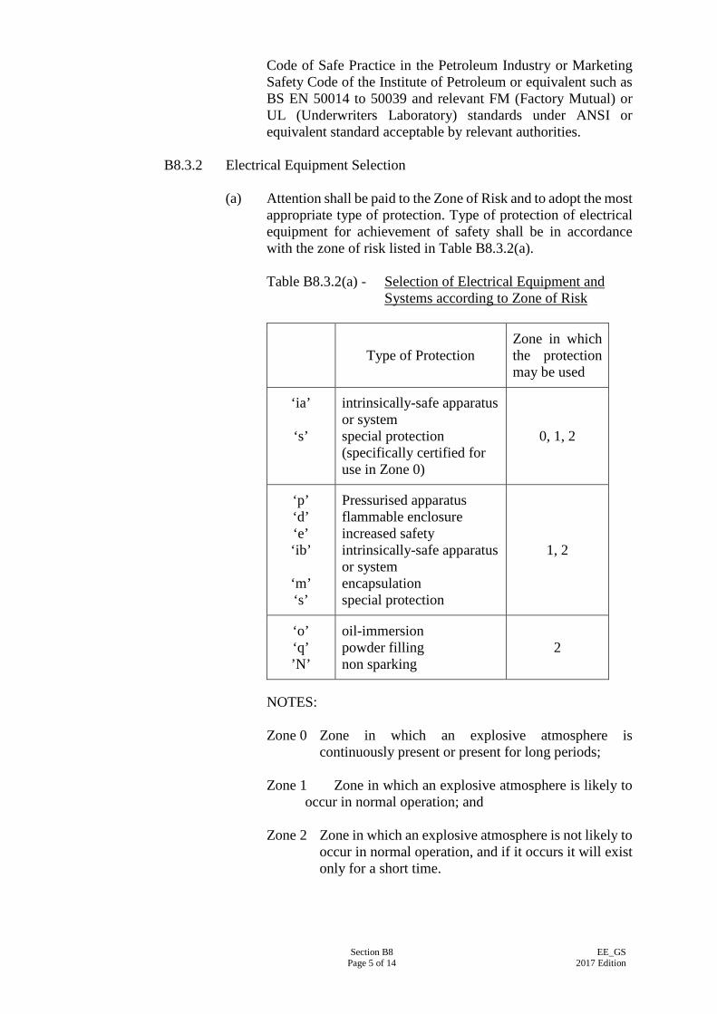
Section B8 Page 5 of 14
EE_GS 2017 Edition
Code of Safe Practice in the Petroleum Industry or Marketing Safety Code of the Institute of Petroleum or equivalent such as BS EN 50014 to 50039 and relevant FM (Factory Mutual) or UL (Underwriters Laboratory) standards under ANSI or equivalent standard acceptable by relevant authorities.
B8.3.2 Electrical Equipment Selection
(a) Attention shall be paid to the Zone of Risk and to adopt the most
appropriate type of protection. Type of protection of electrical equipment for achievement of safety shall be in accordance with the zone of risk listed in Table B8.3.2(a).
Table B8.3.2(a) - Selection of Electrical Equipment and
Systems according to Zone of Risk
Type of Protection
Zone in which the protection may be used
‘ia’
‘s’
intrinsically-safe apparatus or system special protection (specifically certified for use in Zone 0)
0, 1, 2
‘p’ ‘d’ ‘e’ ‘ib’
‘m’ ‘s’
Pressurised apparatus flammable enclosure increased safety intrinsically-safe apparatus or system encapsulation special protection
1, 2
‘o’ ‘q’ ’N’
oil-immersion powder filling non sparking
2
NOTES:
Zone 0 Zone in which an explosive atmosphere is
continuously present or present for long periods; Zone 1 Zone in which an explosive atmosphere is likely to
occur in normal operation; and Zone 2 Zone in which an explosive atmosphere is not likely to
occur in normal operation, and if it occurs it will exist only for a short time.
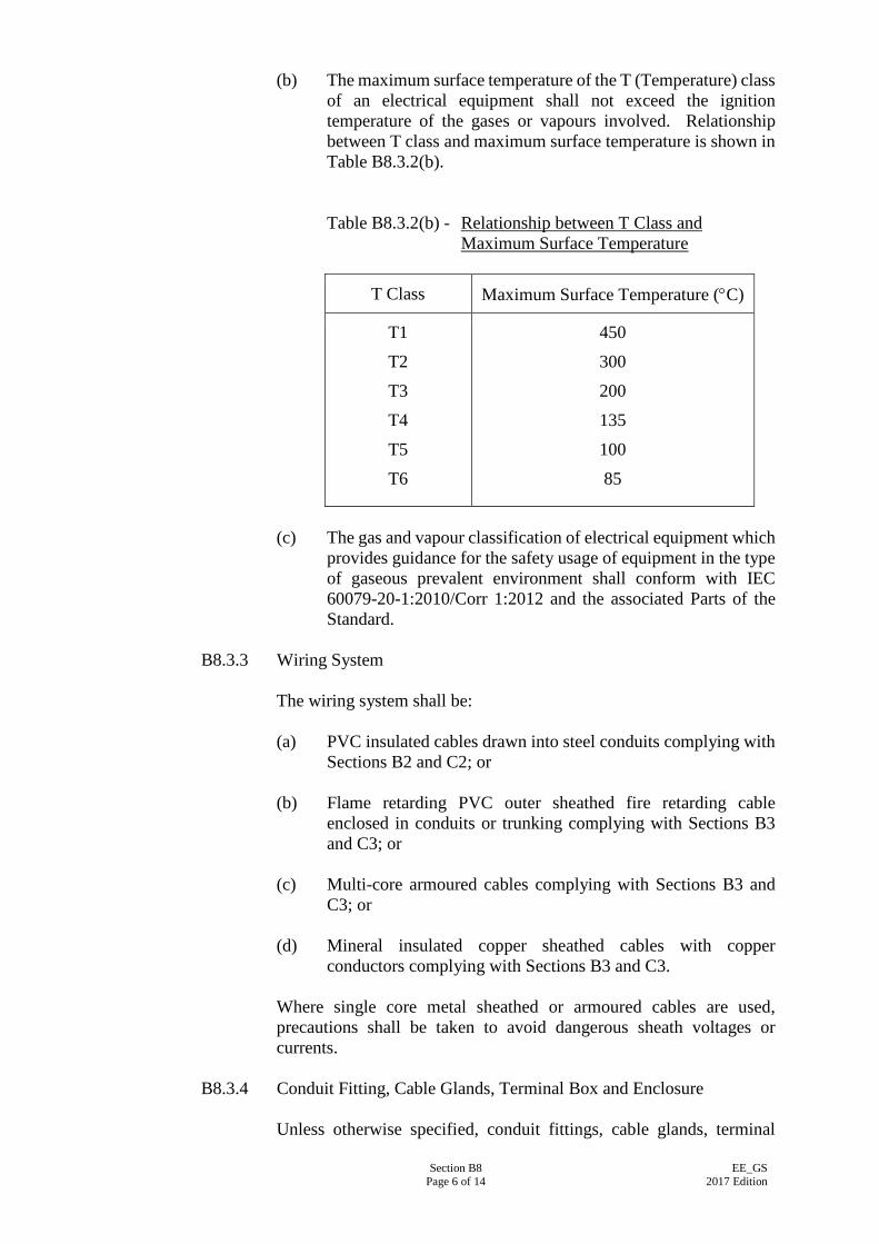
Section B8 Page 6 of 14
EE_GS 2017 Edition
(b) The maximum surface temperature of the T (Temperature) class of an electrical equipment shall not exceed the ignition temperature of the gases or vapours involved. Relationship between T class and maximum surface temperature is shown in Table B8.3.2(b).
Table B8.3.2(b) - Relationship between T Class and Maximum Surface Temperature
T Class Maximum Surface Temperature (°C)
T1
T2
T3
T4
T5
T6
450
300
200
135
100
85
(c) The gas and vapour classification of electrical equipment which
provides guidance for the safety usage of equipment in the type of gaseous prevalent environment shall conform with IEC 60079-20-1:2010/Corr 1:2012 and the associated Parts of the Standard.
B8.3.3 Wiring System
The wiring system shall be: (a) PVC insulated cables drawn into steel conduits complying with
Sections B2 and C2; or (b) Flame retarding PVC outer sheathed fire retarding cable
enclosed in conduits or trunking complying with Sections B3 and C3; or
(c) Multi-core armoured cables complying with Sections B3 and
C3; or (d) Mineral insulated copper sheathed cables with copper
conductors complying with Sections B3 and C3. Where single core metal sheathed or armoured cables are used, precautions shall be taken to avoid dangerous sheath voltages or currents.
B8.3.4 Conduit Fitting, Cable Glands, Terminal Box and Enclosure
Unless otherwise specified, conduit fittings, cable glands, terminal
Section B8 Page 7 of 14
EE_GS 2017 Edition
boxes and enclosures of apparatus (including accessories) shall be suitable for use with Group IIA and Group IIB inflammable gases and vapours as specified in IEC 60079-20-1:2010/Corr 1:2012 with temperature classification of T6 (85°C). Conduit fittings, cable glands and terminal boxes shall carry the registered flameproof mark and manufacturer's certificate number.
B8.3.5 Screw or Bolt Screws or bolts for securing individual components of apparatus and luminaires shall only be removed by the using of a tubular box spanner complying with BS 2558:1954 or a hexagon wrench key complying with BS 2470:2012.
B8.3.6 Luminaire Unless otherwise specified, luminaires shall comply with IEC 60079-0:2007 and the associated parts of the standard and shall be suitable for use in Zone 1 where gases exist is of Group IIA or Group IIB classification as specified in IEC 60079-20-1:2010/Corr 1:2012 with temperature classification of T6 (85oC). Where tubular fluorescent luminaires are specified, they shall have starterless ballasts.
B8.3.7 Conduit Pendant At all tube pendant points, a three-way (tee) circular or rectangular junction box shall be provided. The conduit down drop shall be fitted direct to the threaded spout of the box. Screwed pendant covers shall not be used.
B8.3.8 Cables or Conduits Passing through Floor, Wall or Partition Where cables or conduit passing through a floor, wall or partition that forms a gas or fire barrier, the hole provided for them shall be made good with material determined as incombustible in accordance with the method of BS 476-4:2014 to the full thickness of the floor, wall or partition. Alternatively, cable glands or cable transits may be used for this purpose. Where a run of conduit, irrespective of size, passes from a hazardous area to a non-hazardous area, a stopper box or sealing device shall be inserted at the hazardous area boundary or, failing this, on the side remote from the hazardous area.
B8.3.9 Precautions to Prevent Passage of Inflammables Gases or Vapours Where trunking, ducts, pipes or trenches are used to accommodate cables, precautions shall be taken to prevent the passage of inflammable gases or vapours from one area to another and to prevent the collection of inflammable gases or vapours in trenches. Such precautions shall involve the sealing of trunking, ducts and pipes and the adequate ventilation or sand filling of trenches.
Section B8 Page 8 of 14
EE_GS 2017 Edition
B8.3.10 Equipotential Bonding of Conduit
The metallic portion of conduit shall be electrically bonded to the rigid system by either a separate conductor or terminating devices.
B8.4 EXTERNAL LIGHTING SYSTEM
B8.4.1 Scope This Sub-section covers lighting installations (mainly pole mounted) for street lighting, security lighting, floodlighting and general area lighting.
B8.4.2 Specification and Drawing External lighting installations shall be installed in accordance with the Particular Specification and Drawings.
B8.4.3 Luminaire The type of lamps and luminaires to be used shall be as specified in the Particular Specification and Drawings. The luminaires shall be securely mounted on the poles. For those not mounted on poles, they shall be fixed on wall or hanger, plinth or the like dedicated for the mounting of the luminaires. In such case, the installation shall comply with Clause B4. Where specified in the Particular Specification, a safety chain shall be provided between the luminaire and the lamp pole to ensure that the luminaire will not be dropped down in case the luminaire support fails. The chain shall be galvanised steel and of adequate strength to support at least three times the weight of the luminaire.
B8.4.4 Construction of Lamp Pole Unless otherwise specified, lamp poles shall be constructed of mild steel pipe. The lamp poles shall be hot dipped galvanised to BS EN ISO 1461:2009. Material samples and working drawings shall be submitted when requested by the Supervising Officer. The poles shall be finished overall with at least two coats of primer and two coats of finishing paint after erection in accordance with Clause B1.6. The colour of the finishing paint shall be as directed by the Supervising Officer. The EE Contractor shall submit evidence to substantiate that the lamp poles are structurally sound and are suitable for use in the local environment, in particular under typhoon conditions at a wind speed of up to 80 m/s. Such evidence shall be by means of manufacturer’s calculation and certificates.
Section B8 Page 9 of 14
EE_GS 2017 Edition
All lamp poles shall be earthed by approved means such as the armour of the underground armoured cables.
B8.4.5 Foundation of Lamp Pole Lamp poles shall be securely bolted down in an upright position to the foundations. The EE Contractor shall submit structural calculations through a registered structural engineer to substantiate the foundation is structurally sound and is suitable for use in the local environment, in particular under typhoon conditions at a wind speed up to 80 m/s. Should there be any queries on the construction of the foundations, the Supervising Officer’s advice shall be sought.
B8.4.6 Service Box A galvanised steel service box shall be provided on each pole at an appropriate height above ground level to accommodate the MCB control box. The service box can be integrated with the lamp pole. Each lamp circuit shall be protected by an MCB. Where the CSA of the incoming/outgoing cable cores are larger than that which can be accommodated by the terminal of the MCB, a fixed insulated connector block of adequate rating shall be installed with a tail to the MCB. Alternatively, a copper busbar may be used. Where the service box serves more than one circuit, the supply to the MCB shall be by means of a copper busbar of adequate rating. The phase conductors of the incoming/outgoing cables shall then be terminated to the busbar by means of cable sockets. Each control box shall be fitted with a neutral block of adequate rating and having sufficient number of ways for the incoming/outgoing cable cores. It shall be securely fixed to the base of the control box by means of a 6 mm thick paxolin block. The service box shall be fitted with a 3 mm thick galvanised steel cover made waterproof with a 3 mm thick soft rubber or neoprene gasket. The cover shall be fixed by means of four M6 brass fixing bolts and washers and shall be hinged. Provision shall be made in the batten plate of the box for supporting and terminating up to three numbers of incoming/outgoing XLPE or PVC/SWA & PVCS cables by means of suitable cable glands. The cable sizes shall be as specified in the Particular Specification or on the Drawings.
B8.4.7 Underground Cable to Pole Underground cables for external lighting systems shall be copper cored, XLPE or PVC insulated, steel wire armoured and PVC sheathed cables (XLPE or PVC/SWA & PVCS) unless otherwise specified. Cables shall enter and leave the pole below ground level and each cable shall terminate in a gland fixed to the MCB control box. The cable cores between the glands and the terminals shall not be in tension.
Section B8 Page 10 of 14
EE_GS 2017 Edition
Underground straight through joint will not be permitted without written agreement of the Supervising Officer. All underground cables shall be laid inside cable trenches or ducts. If these ducts are provided by the builder, the EE Contractor shall ascertain that the quantity, size and associated arrangement of the ducts are suitable for drawing of cables in future. Draw pits of adequate sizes shall be provided for a straight run of approximately 15 m, at position where cable route changes direction or as and where required.
B8.4.8 Cable between Service Box and Luminaire Cables from the neutral terminal block and the MCB to the luminaires shall be PVC insulated and PVC sheathed having CSA as specified. Arrangements shall be made to prevent the cores from being under tension where they are attached to terminals. All cables shall be contained within the poles. Rubber grommets shall be installed where cable passes through metal work. Where sustained arc voltage of a discharge lamp exceeds 250 V, the cables used for connecting the lamp and the control-gear shall be of 600/1,000 V grade to IEC 60502-1:2004 and the associated parts of the standard or as recommended by the lamp manufacturer. The length of cables shall not exceed the limit as recommended by the manufacturer. Where flexible cables are recommended by manufacturer for termination at the luminaire, PVC insulated and PVC sheathed flexible cables shall be used. Such cables shall enter the luminaire by means of suitable waterproof compression glands. Where four or more floodlights are mounted on a pole, the flexible cables shall be connected to the luminaires by means of a mild steel connector box with waterproof hinged cover. The connector box shall be fitted near to the top of the pole.
B8.4.9 Switch Fitted to Pole Where specified switches may be mounted on the pole for local control. Switches mounted on the pole shall be fixed onto it by tapped holes and brass fixing screws. The switches shall be waterproof or contained within a waterproof type galvanised metal case, with an external galvanised metal operating knob or handle. Switches shall be fitted at least 2 m above finished ground level.
B8.4.10 Control Gear for Discharge Lighting Control gear for discharge lamps shall be contained within a galvanised steel box mounted on the pole or inside the concrete gear-cabinet provided by others as shown on the Drawings. When mounted on the pole, the steel box shall be watertight and positioned at a height higher than normal working level in such a way that a ladder is
Section B8 Page 11 of 14
EE_GS 2017 Edition
needed for access. The box shall be of adequate size to accommodate all control gear, cable and connections. The method of construction shall be similar to the service box.
B8.4.11 Testing of Illumination Level Testing of the illumination level and distribution of external lighting installations shall be carried out after dark under the direction of the Supervising Officer. All labour, instruments and materials necessary to carry out the test shall be provided including adjustment of the luminaires to achieve the desired illumination level and performance to the satisfaction of the Supervising Officer.
B8.4.12 Numbering of Lamp Pole All lamp poles shall be marked with appropriate identification numbers. The numbers shall commence consecutively from the source of power supply in the clockwise direction. The numbering proposal shall be submitted with the shop drawings to the Supervising Officer for approval. The number shall be etched on a stainless steel plate which shall be fixed onto the pole by tapped holes and two brass fixing screws. The numbers shall not be less than 50 mm tall. A framed drawing indicating the location of lamp poles and pole numbers shall be provided in the appropriate switch room. The framed drawing shall be fixed onto the wall in such a manner that it can easily be removed for reference.
B8.5 LIGHTNING PROTECTION SYSTEM
B8.5.1 Installation of Lightning Protection System Lightning protection systems shall be installed in accordance with the Particular Specification and Drawings, and as directed by the Supervising Officer.
B8.5.2 Scope This Sub-section covers lightning protection systems applicable to buildings and similar structures. It does not cover the protection of overhead lines and other specialized applications. The installation shall conform to the requirements and recommendations set out in IEC 62305-1:2010 and the associated parts of the standard.
B8.5.3 Type of Lightning Protection System A lightning protection system shall comprise air termination connected by down conductors to earthing electrodes. In larger schemes more than one of any or all of the above items may be used. Air terminations
Section B8 Page 12 of 14
EE_GS 2017 Edition
may be interconnected by means of roof horizontal conductors.
B8.5.4 Air Termination Air termination shall consist of vertical or horizontal conductor(s) or combination of both. On a reinforced concrete structure, the air termination shall be connected to the designated reinforcing bars in the number of positions required for down conductors. All metallic projections on or above the main surface of the roof which are connected, intentionally or fortuitously, to the general mass of the earth should be bonded to, and form part of, the air termination network.
B8.5.5 Down Conductor The dimensions of down conductors to be used shall be either of the following: (a) annealed tinned copper strip 25 mm x 3 mm; (b) annealed copper rod 12 mm diameter; or (c) steel reinforcement bar 12 mm diameter. Where the steel work of the structure is used as down conductor, co-ordination with the Building Contractor is required to ensure the continuity of the steel work. In this connection the ends of the steel work shall be connected to the lightning protection system by a jointing method which is suitable for bonding dissimilar metals and approved by the Supervising Officer. A test joint shall be provided at each connection. When down conductors adhered on the external wall are specified, they shall be fixed by means of suitable spacer saddles at regular intervals of not exceeding 1 m apart. The down conductor shall follow the most direct path possible between the air termination network and the earth termination network. When more than one down conductors are installed, they shall be arranged as evenly as practicable around the outside walls of the structure starting from the corners. Each down conductor shall be connected to an earth termination.
B8.5.6 Test Joint Test joints shall be of phosphor bronze, gunmetal or copper. They shall comprise a heavy circular base, to which a heavy circular cover of the same material shall be bolted. The flat copper conductor shall be overlapped and placed so that they are clamped between the cover and the base by means of at least four screws or studs.
Section B8 Page 13 of 14
EE_GS 2017 Edition
The test joints shall be positioned so that they shall not be tampered with by unauthorised persons. In cases where this is not possible, the earth tape/rod connector clamp shall be used as an alternative test point in place of the test joint.
B8.5.7 Earth Termination Unless otherwise specified, earth termination shall be of rod electrodes complying with Clause B7.3. Each earth termination shall have a resistance to earth not exceeding the product given by 10Ω times the number of earth terminations to be provided. The whole of the lightning protection system shall have a combined resistance to earth not exceeding 10Ω. Where, due to local conditions, it is difficult to obtain a value of less than 10Ω by the sole use of rod electrodes, alternative or additional methods, e.g. the use of deep bore holes, the installation of tape or plate electrodes complying with Section B7, may be used at the discretion of the Supervising Officer.
B8.5.8 Spacer Saddle Spacer saddles shall be of high quality metal. For copper conductors, brass or gunmetal shall be used. Non-metallic spacer saddles shall only be used when down conductors are provided with PVC sheathing.
B8.5.9 Connection to Earth Termination Down conductors and bonding conductors shall be connected to the earth electrode in accordance with Clause B7.4. Each connection shall be separately clamped and shall be fitted with a warning notice in accordance with Clause B1.2.
B8.5.10 Bonding to Other Services Lightning protection systems shall normally be kept segregated from the metalwork of other services. Minimum isolation clearances as given in IEC 62305-1:2010 and the associated parts of the standard. shall be maintained. However, in certain circumstances, e.g. where fortuitous contact with other systems cannot be avoided, earth electrodes for lightning protection may, at the discretion of the Supervising Officer, be bonded to other such services including the metal sheath and armouring of low voltage cables, the consumer's low voltage earth system, metal water pipes and steel reinforcement for the foundation and structure. Cables and earthing systems belonging to the Supply Authorities, the Telephone Company and other authorities shall not be bonded except with the written permission of such Authorities. Gas pipes shall not normally be connected to any earth electrode.
Section B8 Page 14 of 14
EE_GS 2017 Edition
B8.5.11 Bond
Bonds for use in connecting the lightning protection system of other metal work shall be of soft annealed copper strip of 25 x 3 mm. Bonds connecting movable items to the lightning protection system shall be of flexible copper strand 475/0.5 mm diameter or equivalent. Connections to other metalwork shall be of negligible resistance, metal to metal and mechanically sound with non-ferrous nuts, bolts and washers using clamps where necessary.
B8.5.12 Joint in Conductors Joints in roof conductors and/or down conductors shall be made by double riveting or by suitable tape clamps. When clamps are used, the tape clamps shall each be provided with at least 4 screws or bolts. All such joints shall be tinned and shall have negligible resistance and good mechanical strength. Alternatively, connectors may be jointed together by means of exothermic or thermal welding utilising the high temperature reaction of powdered copper oxide provided that the proper material and equipment are used in accordance with the manufacturer's recommended process.
B8.5.13 Testing On completion of the installation, the lightning protection system shall be tested for continuity between air terminations and earthing terminations and the resistance shall be recorded. The earthing resistance of each earthing electrode shall also be tested and recorded. The tests shall be carried out in accordance with Part D of this Specification and shall be submitted to the Supervising Officer for approval. All instruments used for testing shall be properly calibrated.
Section B9 Page 1 of 6
EE_GS 2017 Edition
SECTION B9
INSTALLATION OF ELECTRIC MOTORS AND HIGH VOLTAGE EQUIPMENT
B9.1 LOW VOLTAGE-ELECTRIC MOTORS B9.1.1 Maintenance Access and Safety
(a) Adequate access to the motors and their associated facilities
shall be allowed such that the necessary periodical testing, cleaning and maintenance can be carried out. The motors shall not be installed in a position where surrounding plant or building work may obstruct in meeting such requirements.
(b) Each electric motor, electric air heater battery or other electrical
device which is controlled from the main control panel and is so situated that the panel is at a distance and/or out of sight from the equipment. shall be provided with a local 'stop-lock' control circuit switch (where there is a separate control circuit), plus a local main power supply circuit isolator in all such cases.
B9.1.2 Terminals
Exception for armoured cables, all other cables appearing above floor level shall be enclosed in approved trunking, solid or flexible conduit, with approved provision for movement of the motor. The terminal boxes for cable connection shall be suitably arranged to make a neat joint with the conduits or cables.
B9.1.3 Anti-Condensation Heater The anti-condensation heater shall be controlled such that the heater shall be de-energised when the starter is switched on and vice versa. Heaters shall be wired from the motor control panel.
B9.1.4 Belt Drives and Pulleys Pulleys shall be correctly aligned and any holding down bolts or fixings shall be positioned to ensure correct alignment. Slide rails shall be provided for all motors driving through belts. Purpose-made adjusting devices shall be provided to adjust the belt tension and to secure the motors.
B9.1.5 Protective Guards The protective guards shall be rigidly constructed. It shall not be possible to remove any guard without the aid of a tool.
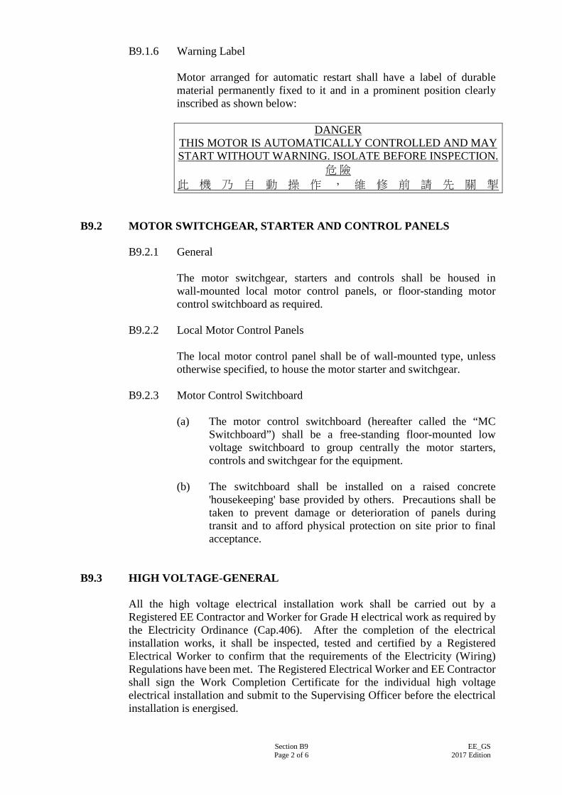
Section B9 Page 2 of 6
EE_GS 2017 Edition
B9.1.6 Warning Label Motor arranged for automatic restart shall have a label of durable material permanently fixed to it and in a prominent position clearly inscribed as shown below:
DANGER THIS MOTOR IS AUTOMATICALLY CONTROLLED AND MAY START WITHOUT WARNING. ISOLATE BEFORE INSPECTION.
危 險 此 機 乃 自 動 操 作 , 維 修 前 請 先 關 掣
B9.2 MOTOR SWITCHGEAR, STARTER AND CONTROL PANELS
B9.2.1 General The motor switchgear, starters and controls shall be housed in wall-mounted local motor control panels, or floor-standing motor control switchboard as required.
B9.2.2 Local Motor Control Panels The local motor control panel shall be of wall-mounted type, unless otherwise specified, to house the motor starter and switchgear.
B9.2.3 Motor Control Switchboard (a) The motor control switchboard (hereafter called the “MC
Switchboard”) shall be a free-standing floor-mounted low voltage switchboard to group centrally the motor starters, controls and switchgear for the equipment.
(b) The switchboard shall be installed on a raised concrete
'housekeeping' base provided by others. Precautions shall be taken to prevent damage or deterioration of panels during transit and to afford physical protection on site prior to final acceptance.
B9.3 HIGH VOLTAGE-GENERAL
All the high voltage electrical installation work shall be carried out by a Registered EE Contractor and Worker for Grade H electrical work as required by the Electricity Ordinance (Cap.406). After the completion of the electrical installation works, it shall be inspected, tested and certified by a Registered Electrical Worker to confirm that the requirements of the Electricity (Wiring) Regulations have been met. The Registered Electrical Worker and EE Contractor shall sign the Work Completion Certificate for the individual high voltage electrical installation and submit to the Supervising Officer before the electrical installation is energised.
Section B9 Page 3 of 6
EE_GS 2017 Edition
B9.4 HIGH VOLTAGE - ELECTRIC MOTORS
B9.4.1 Motor Foundation
A motor bedplate/foundation block shall be provided unless the motor is to be mounted on the soleplate of the driving equipment such as compressor or pump. Jacking screws shall be fitted at perpendicular directions on the foundation block for alignment of the coupling.
B9.4.2 Provision for Cabling and Termination
(a) Cabling Provision at Bedplates Provision shall be made in the steel bedplate where necessary to facilitate straight run of cable to the bottom of the motor cable terminal box.
(b) Cabling Provision at Motor Casing The terminal leads from cable box terminals or connectors to the windings for a distance of 150 mm beyond their point of entry into the motor frame shall be adequately braced to withstand the forces produced by maximum fault current. The phase windings shall be accessible for testing. For this purpose, neutral leads shall be brought out to a separate star-point terminal box and shorted with an insulated copper bar of cross-sectional area not less than the conductor of the terminal lead. Studs shall be so fixed as to prevent the terminal leads from turning when the nuts are tightened down. Means shall be provided to prevent slackening of cable connections due to vibration.
(c) Motor Termination Boxes The termination of motor supply cables shall be done by bolts and nuts on to stud terminal stems, and so designed that the motor can be removed to another location with the termination chamber in-situ. No cable joint is permitted in the termination chamber. Front access detachable cover plates shall be fixed by studs and nuts. Separate plates shall be supplied for termination chambers. Joints shall be machined flat and fitted with neoprene rubber gaskets. A shroud having a minimum breakdown voltage of 20 kV shall be fitted over each cable terminal.
Section B9 Page 4 of 6
EE_GS 2017 Edition
B9.5 HIGH VOLTAGE MOTOR CONTROL SWITCHBOARD
B9.5.1 General Requirements
(a) The switchboard shall be mounted firmly on to the concrete floor finished to the standard requirements as recommended by the equipment manufacturer. The floor construction shall be designed to withstand the operating weight and impact loading of the switchboard. Individual panels shall be erected to true plumb vertically and horizontally on suitable guides/rails as standard accessories from the same manufacturer.
(b) The height of the instrument panel above floor level shall not
exceed 2,400 mm. All panels constituting a complete switchboard shall be of equal height.
(c) Bolted on rear and top covers shall be designed to gain access to
individual circuits without exposing other circuits which may be alive. Switchboards shall not be located across floor expansion joints.
(d) Before steelworks is painted, it shall be treated and degreased
by an approved method such as grit blasting to ISO 8502:2006 or chemical pickling and an approved anti-rusting priming coat applied. The panels shall be externally finished in semi-gloss stoved enamel or cellulose to a colour to be approved by the Supervising Officer.
B9.5.2 Primary Busbars and Connections
(a) At all points where connections or joints occur, the busbars and connecting pieces shall be tinned or silver-plated. The resistance of any length of conductor containing a joint shall not be greater than that of an equal length without a joint.
(b) Jointing of sections of busbars shall be done by mechanical
means. Soldered, braced, welded or riveted joints shall not be used in busbars. Jointing faces of copper conductors shall be tinned or silver plated, or other approved treatment to maintain effective conductivity of the joint. All necessary busbar jointing bolts, nuts, and fixing accessories shall be provided. The recommended torque for tightening the bolts shall be stated in the maintenance manual.
B9.5.3 Anti-Condensation Heaters
They shall be thermostatically controlled and shall operate at black heat and shall be shrouded and located so as not to cause injury to personnel or damage to equipment. The heaters shall be controlled from a double-pole miniature circuit-breaker, with a lamp to indicate
Section B9 Page 5 of 6
EE_GS 2017 Edition
'cubicle heaters on'. The circuit-breaker and indicating lamp shall be mounted externally at one end of the switchboard.
B9.5.4 Cables Boxes
(a) Cable boxes shall be suitable for terminating the cables directly into the switchgear.
(b) Where cable boxes are used for three-core cables, the sweating
sockets on the two outer phases shall be so fixed to incline towards the centre to minimise bending of the cable cores. Where there is more than one core per phase, the socket block shall be so fixed as to minimise bending of the cable cores, and spacer clips shall be used.
B9.5.5 Labels and Warning Notice
(a) Labels shall be fixed by screws on the non-detachable parts of the panel at a height of 1350 mm or above.
(b) 'Danger - H.V. Live Terminals/ 危險 – 高壓帶電電極' warning
labels shall be attached to the access covers of the air insulated cable boxes, CT chambers and busbar, and shall be coloured red with white lettering in both English & Chinese characters.
(c) In addition to automatic screening shutters and barriers,
warning labels shall also be provided for all live parts, such as test terminal blocks.
B9.6 HIGH VOLTAGE AUTO-TRANSFORMERS
B9.6.1 The auto-transformers shall be mounted firmly on to the concrete floor finished to the standard requirements as recommended by the equipment manufacturer. The floor construction shall be designed to withstand the operating weight of the auto-transformers.
B9.6.2 The installation shall be carried out in strict accordance with the
recommendations so as to keep the noise and vibration generated by the auto-transformers to the minimum.
B9.7 HIGH VOLTAGE POWER FACTOR CORRECTION CAPACITORS
B9.7.1 Positioning of the power factor correction capacitors shall be done by means of the built-in combined jacking and haulage lugs.
B9.7.2 The installation shall strictly follow the equipment manufacturer’s
recommendations.
Section B9 Page 6 of 6
EE_GS 2017 Edition
B9.8 HIGH VOLTAGE POWER CABLES
B9.8.1 No straight through cable joints shall be installed without the approval of the Supervising Officer.
B9.8.2 For identification, the rating of the cable shall be impressed into the
outer insulation at regular intervals. B9.8.3 The radius of each bend or change in direction in the route of a cable
shall not be less than eight times the overall diameter of the cable or as technically recommended by the cable manufacturer whichever is more stringent.
B9.8.4 Cable Terminations
Cables shall be terminated by approved non-ferrous mechanical glands complete with compression devices for securing the cable sheath. An armour clamp shall be provided for bonding to metal sheaths as necessary. Where the cables are installed in entirely dry situations, the gland shall be designed with a compressible gasket or packing for securing the inner sheath and anchoring the armour. For cables installed wholly or partly in outdoor or damp conditions, compressible sealing and clamping features shall be provided for securing the inner and outer sheaths and also the armour; barriers shall be incorporated to prevent the ingress of moisture. Other types of cable termination can be used subject to the approval of Supervising Officer.
Section C1 Page 1 of 4
EE_GS 2017 Edition
PART C – MATERIAL AND EQUIPMENT SPECIFICATION
SECTION C1
GENERAL
C1.1 MATERIAL AND EQUIPMENT
C1.1.1 International Standards
Material and equipment shall be of high quality, and shall comply with, where applicable, the appropriate International Standard Specifications prepared by IEC or ISO Technical Committees together with any amendments made thereto. The EE Contractor can propose the relevant parts of the stated standard for the offered equipment and materials to comply with for approval by the Supervising Officer.
C1.1.2 Other Standard Specifications When material or equipment complying with other standard specifications is offered, the EE Contractor shall satisfy the Supervising Officer that the quality of the equipment offered is equal to or better than that specified in the appropriate International Standards (IEC/ISO).
C1.1.3 Service Conditions The following service conditions shall apply: (a) Climate: Hong Kong (tropical); (b) Ambient temperature:
Peak -5°C to +40°C (continuously 4 hours) Average 0°C to +35°C (over 24 hours);
(c) Altitude: up to 2,000 m above sea level; and (d) Relative humidity: 99% maximum or non-condensing.
C1.1.4 Selection of Equipment Selection of equipment shall be based on this Specification, the Particular Specification, and technical data contained on the Drawings for a particular installation. An assessment should be made of any characteristics of equipment likely to have harmful effects upon other electrical equipment or other services, or impair the supply. Those characteristics include the following:
Section C1 Page 2 of 4
EE_GS 2017 Edition
(a) overvoltages; (b) undervoltages; (c) fluctuating loads; (d) unbalanced loads; (e) power factor; (f) starting currents; (g) harmonic currents; (h) DC feedback; (i) high-frequency oscillations; and (j) necessity for additional connection to earth. Where items of equipment are interconnected to form an integral part of the complete electrical installation, their characteristics of performance and capacities shall be so matched as to give safe, reliable, efficient and economical operation of the complete electrical installation. Whenever equipment are called for in the Particular Specifications or Drawings for the Installations of a particular job, all these equipment shall conform to the energy efficiency requirements as stipulated in the Building Energy Code.
C1.1.5 Equipment Catalogue and Manufacturer’s Specification
Equipment catalogues and manufacturers’ specifications related to the proposed equipment shall be in the Chinese or English language, be specific and shall include all information necessary for the Supervising Officer to ascertain that the equipment complies with this Specification and Drawings. Data and sales catalogue of a general nature will not be accepted unless prior agreement has been obtained from the Supervising Officer. Equipment catalogues and manufacturers’ specifications must be submitted for the examination and agreement of the Supervising Officer before any equipment is ordered.
C1.2 VOLTAGE COVERED BY THIS SPECIFICATION
Unless otherwise specified, all apparatus, equipment, materials and wiring shall be suitable for use with a 3-phase and neutral, 4-wire, 380/220 V +6%,
Section C1 Page 3 of 4
EE_GS 2017 Edition
50 Hz ±2% source neutral earthed system with provision of bonding to the Electricity Supplier’s bonding terminal.
C1.3 INSULATING MATERIAL
Insulating tapes for low voltage applications shall comply with IEC 60454-3-1:2002 pressure sensitive adhesive tape type F-PVCp/90/0/Tp (Plasticized PVC) and have a thickness of not less than 0.22 mm. Non-impregnated paper, fabric, wood or press-hemp shall not be used for insulating purposes. Where synthetic resin bonded insulating boards are used, all cut edges shall be sealed with an approved varnish. When insulating material complying with other standard specifications is offered, the EE Contractor shall satisfy the Supervising Officer that the quality of the insulating material offered is equal to or better than that specified in the appropriate IEC Standards.
C1.4 MINIMUM SIZE OF CABLE CONDUCTOR
Cables for lighting and bell circuits shall have CSA of not less than 1.0 mm², and those for power circuits shall have CSA of not less than 2.5 mm². Internal wiring in factory made panel or equipment may comprise cables of different suitable CSA determined by the manufacturer. The CSA of any cable shall not be reduced at its point of termination, junction, joints, etc. Where cables of 1.0 mm2 are to be terminated, approximately 15 mm long of cable insulation shall be removed and half the length of the bare conductor shall be bent into the other half to form a solid part prior to the insertion into the termination.
C1.5 USE OF PVC-INSULATED CABLE AT LOW TEMPERATURE
PVC-insulated cables shall not be installed in refrigerated space or other situations where the temperature is consistently below 0°C.
C1.6 FIXING SCREW AND BOLT
Machine screws and nuts shall be to ISO 885:2000. Hexagon bolts, screws and nuts shall be to BS EN ISO 4016:2011, BS EN ISO 4018:2011 and BS EN ISO 4034:2012. Holes for bolts, screws and other fixings shall be drilled or stamped, and no larger than required for clearance of the bolt, screw, etc.
C1.7 SHEET METAL WORK
Sheet metal boxes, meter chambers, etc. shall be manufactured from plain steel sheets. The thickness of steel sheet shall be as specified in the Particular
Section C1 Page 4 of 4
EE_GS 2017 Edition
Specification and subject to a minimum of 1.0 mm. Where necessary, suitable stiffeners shall be provided to give adequate rigidity. Protection against corrosion shall be achieved by means of hot-dip galvanisation, anti-rust painting or enamel, or the use of stainless steel. If stainless steel sheet is specified, it shall be to ISO 683-13:1986, Table 3 “Type of Condition and Surface Condition of Stainless Steel Products” Symbol F9 for matt finish and Symbol F8 for polished finish.
C1.8 CABLE MARKERS IN ADDITION TO CABLE COLOUR
IDENTIFICATION Cable markers where necessary shall be provided to cables in addition to their colour identifications. C1.8.1 Cable markers for identification purposes shall comply with
BS 3858:1992. C1.8.2 The physical dimensions of cable markers and all necessary
accessories shall suit and fit the sizes of cables. Cable markers shall either be of closed type which have to be fitted to the cable before physical connection of cables or of open type which can be directly attached to the cables after connection.
C1.8.3 The materials used for the cable markers and carrier strips shall be
made from Halogen-free materials and flame resistance, having a service temperature range between -40oC to +70oC. They shall be of high mechanical strength , rigidity and hardness characteristics. The material shall also be chemical resistance against sodium hydroxide, seawater, detergent, petrol, diesel, sodium chloride solution, nitric acid, ammonium hydroxide, etc. The colour of cable markers shall be YELLOW in accordance with the international colour-code.
C1.8.4 The identification markings on the cable markers shall be printed in
BLACK colour. The printed characteristics shall withstand all the usual marker tests pertaining to resistance to smearing and scratching, and imperious to solvents such as acetone.
Section C2 Page 1 of 11
EE_GS 2017 Edition
SECTION C2
WIRING SYSTEM: CABLES, CONDUITS, TRUNKING AND ACCESSORIES
C2.1 CABLES IN WIRING SYSTEM
C2.1.1 General
Wiring cables shall be manufactured under a recognised quality surveillance scheme (e.g. British Approvals Service for Cables (BASEC) licence or the HAR scheme recognised by the European Committee for Electrotechnical Standardization, CENELEC, etc.) and bear the appropriate marking (e.g. BASEC mark or HAR mark, etc.) of the quality surveillance scheme.
Cables in wiring system shall be one or a combination of the following types.
C2.1.2 Non-sheathed Cables
Non-sheathed cables shall be to: (a) 450/750 V PVC insulated, single-core, non-sheathed copper
cables, with solid or stranded conductor for general purpose, suitable for conductor operating temperature not exceeding 70oC – code designation 60227 IEC 01 of IEC 60227-3:1993/Amd 1:1997;
(b) 450/750 V PVC insulated, single-core, non-sheathed copper
cables with flexible conductor for general purpose, suitable for conductor operating temperature not exceeding 70oC – code designation 60227 IEC 02 of IEC 60227-3: 1993/Amd 1:1997;
(c) 300/500 V heat resistant ethylene-vinyl acetate rubber or other
equivalent synthetic elastomer insulated, single-core, non-sheathed copper cable, with solid conductor, suitable for conductor operating temperature not exceeding 110oC – code designation 60245 IEC 06 of IEC 60245-7:1994/Amd 1:1997;
(d) 450/750 V heat resistant ethylene-vinyl acetate rubber or other
equivalent synthetic elastomer insulated, single-core, non-sheathed copper cable, with solid or stranded conductor, suitable for conductor operating temperature not exceeding 110oC – code designation 60245 IEC 04 of IEC 60245-7:1994/Amd 1:1997;
(e) 450/750 V thermosetting insulated, single-core non-sheathed,
copper cable, with solid or stranded conductor, with low emission of smoke and corrosive gases when affected by fire, suitable for conductor operating temperature not exceeding
Section C2 Page 2 of 11
EE_GS 2017 Edition
90oC – code designation H07Z-U and H07Z-R of BS EN50525-3-41:2011; or
(f) 450/750 V, fire resistant, thermosetting insulated, single core,
non-sheathed copper cable, with solid or stranded conductor, with low emission of smoke and corrosive gases when affected by fire, suitable for conductor operating temperature not exceeding 90 oC. Fire resistant cable shall also comply with the fire performance requirement specified in Clause C2.1.6.
C2.1.3 Sheathed Cables
Sheathed cables shall be to: (a) 600/1,000 V PVC insulated, single-core or multi-core, PVC
sheathed, with or without armour, copper cables with solid or stranded conductor, suitable for conductor operating temperature not exceeding 70oC – IEC 60502-1: 2004/Amd 1:2009;
(b) 600/1,000 V PVC insulated, single-core or multi-core,
thermoplastic polyethylene (PE) sheathed, with or without armour, copper cables with solid or stranded conductor, suitable for conductor operating temperature not exceeding 70oC – IEC 60502-1: 2004/Amd 1:2009;
(c) 600/1,000 V cross-linked polyethylene (XLPE) insulated,
single-core or multi-core, PVC sheathed, with or without armour, copper cables with solid or stranded conductor, suitable for conductor operating temperature not exceeding 90oC – IEC 60502-1: 2004/Amd 1:2009;
(d) 600/1,000 V ethylene propylene rubber (EPR) insulated,
single-core or multi-core, PVC sheathed, with or without armour, copper cables with solid or stranded conductor, suitable for conductor operating temperature not exceeding 90oC – IEC 60502-1: 2004/Amd 1:2009;
(e) 300/500 V light PVC insulated, multi-core, PVC sheathed
copper cable with solid or stranded conductor, suitable for conductor operating temperature not exceeding 70oC – code designation 60227 IEC 10 of IEC 60227-4: 1992/Amd 1:1997;
(f) 300/500 V PVC insulated, single-core, flat twin or 3-core, PVC
sheathed copper cable with solid or stranded conductor, suitable for conductor operating temperature not exceeding 70oC – national type (Table 3) of BS 6004:2012;
(g) 300/500 V PVC insulated, single-core, flat twin or 3-core, PVC
sheathed copper cable with solid or stranded conductor and circuit protective conductor, suitable for conductor operating
Section C2 Page 3 of 11
EE_GS 2017 Edition
temperature not exceeding 70oC – national type (Table 4) of BS 6004:2012;
(h) 300/500 V PVC insulated, single-core or flat twin, PVC
sheathed copper cable with stranded conductor and with or without circuit protective conductor, suitable for conductor operating temperature not exceeding 70oC – national type (Table 5) of BS 6004:2012;
(i) 450/750 V thermosetting insulated, twin, 3-core, 4-core or
5-core, sheathed copper cable with solid or stranded conductor, with low emission of smoke and corrosive gases when affected by fire, suitable for conductor operating temperature not exceeding 90oC – national type (Table 4) of BS 7211:2012;
(j) 300/500 V thermosetting insulated, single-core, flat twin or flat
3-core, sheathed copper cable with solid or stranded conductor and circuit protective conductor, with low emission of smoke and corrosive gases when affected by fire, suitable for conductor operating temperature not exceeding 90oC – national type (Table 5) of BS 7211:2012;
(k) 300/500 V fire resistant, thermosetting insulated, twin, 3-core
or 4-core, sheathed copper cable with solid or stranded conductor and un-insulated circuit protective conductor, with low emission of smoke and corrosive gases when affected by fire, suitable for conductor operating temperature not exceeding 90 oC – BS 7629-1:2015. Fire resistant cable shall also comply with the fire performance requirement specified in Clause C2.1.6;
(l) 600/1,000 V cross-linked polyethylene (XLPE) insulated,
single-core or multi-core, sheathed with or without armour, copper cables with solid or stranded conductor and with low emission of smoke and corrosive gases when affected by fire, suitable for conductor operating temperature not exceeding 90oC – IEC 60502-1: 2004/Amd 1:2009; or
(m) 450/750 V, fire resistant, thermosetting insulated, single-core
or multi-core, sheathed with or without armour copper cables, with solid or stranded conductor and with low emission of smoke and corrosive gases when affected by fire, suitable for conductor operating temperature not exceeding 90 oC. Fire resistant cable shall also comply with the fire performance requirement specified in Clause C2.1.6.
C2.1.4 Flexible Cables
Flexible cables shall be: (a) 300/500 V ordinary PVC insulated, multi-core, PVC sheathed
flexible copper cable, suitable for conductor operating
Section C2 Page 4 of 11
EE_GS 2017 Edition
temperature not exceeding 70oC – code designation 60227 IEC 53 of IEC 60227-5:2011;
(b) 300/500 V ordinary tough rubber insulated, multi-core, rubber
sheathed flexible copper cable, suitable for conductor operating temperature not exceeding 60oC – code designation 60245 IEC 53 of IEC 60245-4:2011;
(c) 450/750 V rubber insulated, single-core or multi-core, heavy
polychloroprene or other equivalent synthetic elastomer sheathed flexible copper cable, suitable for conductor operating temperature not exceeding 60oC – code designation 60245 IEC 66 of IEC 60245-4:2011;
(d) 300/500 V PVC insulated, single-core or twisted twin,
non-sheathed flexible copper cable, suitable for internal wiring and conductor operating temperature not exceeding 70oC – code designation H05V-K of BS EN50525-2-31:2011;
(e) 300/500 V PVC insulated, single-core or twisted twin,
non-sheathed heat resisting flexible copper cable, suitable for internal wiring and conductor operating temperature not exceeding 90oC – code designation H05V2-K of BS EN50525-2-31:2011;
(f) 300/500 V braided, silicone rubber insulated, single core,
non-sheathed flexible copper cable, suitable for conductor operating temperature not exceeding 180oC – code designation H05SJ-K of BS EN50525-2-41:2011;
(g) 300/500 V flexible copper cable, suitable for use with appliance
and equipment intended for domestic, office and similar environments to BS EN50525-2-11:2011;
(h) 300/500 V ordinary duty rubber insulated, 3-core or 4-core,
sheathed flexible copper cable, suitable for conductor operating temperature not exceeding 60oC – code designation H05RR-F of BS EN50525-2-21:2011;
(i) 450/750 V heavy duty rubber insulated, single-core, twin,
3-core, 4-core or 5-core, PCP or equivalent synthetic elastomer sheathed flexible copper cable, suitable for conductor operating temperature not exceeding 60oC – code designation H07RN-F of BS EN50525-2-21:2011;
(j) 450/750 V heavy duty heat resisting ethylene propylene rubber
(EPR) or equivalent synthetic elastomer insulated, single-core, twin, 3-core, 4-core or 5-core, and CSP or equivalent synthetic elastomer sheathed flexible copper cable, suitable for conductor operating temperature not exceeding 90oC – code designation H07BN4-F of BS EN50525-2-21:2011;
Section C2 Page 5 of 11
EE_GS 2017 Edition
(k) 300/500 V heat resistant, ethylene-vinyl acetate rubber or other equivalent synthetic elastomer insulated, single-core, non-sheathed flexible copper cable, suitable for conductor operating temperature not exceeding 110oC – code designation 60245 IEC 07 of IEC 60245-7:1994/Amd 1:1997;
(l) 450/750 V heat resistant, ethylene-vinyl acetate rubber or other
equivalent synthetic elastomer insulated, single-core, non-sheathed flexible copper cable, suitable for conductor operating temperature not exceeding 110oC – code designation 60245 IEC 05 of IEC 60245-7:1994/Amd 1:1997; or
(m) 300/500 V heat resistant, silicone rubber insulated, single-core,
non-sheathed flexible copper cable, ,suitable for conductor operating temperature not exceeding 180oC - code designation 60245 IEC 03 of IEC 60245-3:1994/Amd 1:1997/Amd 2:2011.
C2.1.5 Conductor
Conductors of wiring cables shall be of high-conductivity copper and all meet the requirements of IEC 60228:2004. The CSA of the neutral conductor shall not be less than that of the phase conductors, unless otherwise specified.
C2.1.6 Fire Performance of Fire Resistant Cables The materials for insulation and outer covering, if exists, of fire resistant cable shall be of low emission of smoke and corrosive gases characteristics when affected by fire. Fire resistant cable shall be type tested to the following fire performance requirement: (i) Circuit integrity : BS 6387:2013; (ii) Flame propagation : IEC 60332-1-1:2004/Amd 1:2015, IEC 60332-1-2:2004/Amd 1:2015 or IEC 60332-3-24:2000/Amd 1:2008 (iii) Smoke emission : IEC 61034-2:2005/Amd 1:2013; and (iv) Acid gas emission : IEC 60754-1:2011/Corr 1:2013, IEC 60754-2:2011, BS EN 60754-1:2014 or BS EN 60754-2:2014.
Section C2 Page 6 of 11
EE_GS 2017 Edition
C2.2 STEEL CONDUIT AND ACCESSORIES
C2.2.1 Steel Conduit
Steel conduits, except flexible conduits, shall be of heavy gauge, screwed, longitudinally welded. All steel conduits shall comply with IEC 61386-21:2002.
C2.2.2 Steel Flexible Conduit
Steel flexible conduits and solid type brass adaptors shall comply with IEC 61386-23:2002. In addition, the steel flexible conduits shall be metallic type with PVC oversheath. Oversheath materials of low emission of smoke and corrosive gas characteristics shall be provided where specified. However, neither oversheath of PVC nor materials with low emission of smoke and corrosive gas characteristics shall be required for installations within ventilated ceiling void. The flexible conduit adaptor shall comprise two parts, an inner core and an outer ferrule. The inner core screws into the bore of the conduit together with an outer ferrule which caps off the end of the conduit, so that the adaptor can provide an extremely strong joint. The core shall lock against the outer ferrule and isolate any sharp cut edges in the conduit.
C2.2.3 Steel Conduit Fitting
All steel conduit fittings shall comply with IEC 61386-21:2002 and other associated Parts of the Standard. Adaptable boxes complete with covers shall be of cast iron or galvanised steel. Boxes of the preferred sizes as given in IEC 60670-1:2003 and other associated Parts of the Standard shall be used. Circular boxes, dome covers and hook covers shall be of galvanised malleable cast iron complying with IEC 60670-1:2015. Ceiling mounted boxes shall be of deep pattern type having an internal depth of not less than 60 mm. Bushes and tube ends shall be of brass. Distance (spacing) saddles shall be of galvanised cast iron. The screws for tightening and fixing the saddles shall be of brass. Solid or inspection tee-pieces or elbows shall NOT be used on any conduit installation.
C2.2.4 Metal Boxes for Electrical Accessories
Metal boxes complete with covers for enclosure of electrical accessories in conduit installation shall comply with
Section C2 Page 7 of 11
EE_GS 2017 Edition
IEC 60670-1:2015. Boxes used to house accessories such as domestic switches, socket outlets, spur units, etc. shall be 35 mm and 47 mm deep. The depth chosen shall be suitable for the accessories to be housed.
C2.2.5 Class of Protection against Corrosion
Steel conduits and couplers shall be hot-dip zinc coated or sheradized both inside and outside against corrosion and shall be tested to comply with IEC 61386-1:2008. Steel or ferrous conduit fittings shall be hot-dip zinc coated or sheradized both inside and outside against corrosion and shall be tested to comply with IEC 61386-1:2008. Metal boxes complete with covers for the enclosure of electrical accessories shall have heavy protection both inside and outside in accordance with IEC 60670-1:2015 (e.g. hot-dip galvanised coating or sheradizing).
C2.2.6 Screw
Screws used for fixing boxes and spacing saddle, and for tightening covers and spacing saddles shall have ISO metric threads. They shall be of brass or steel and if of steel they shall be protected against corrosion by a finish at least equal to the zinc coating specified in BS 3382-2:1961. Electro-brass plated screws or self tapping screws shall NOT be used.
C2.3 PLASTIC OR PVC CONDUIT AND ACCESSORIES
C2.3.1 Rigid Conduit and Conduit Fittings
Rigid plain PVC conduits shall comply with IEC 61386-21:2002 and rigid plain PVC conduit fittings shall comply with IEC 61386-1:2008 and other associated Parts of the Standard. Conduits shall have classification as below: (a) According to mechanical properties - for heavy mechanical
stress; and
(b) According to temperature - with a permanent application temperature range of -5°C to +60°C.
C2.3.2 Pliable Conduit
Pliable conduits shall be formed of self-extinguishing plastic materials and shall comply with IEC 61386-22:2002 and pliable conduit fittings shall comply with IEC 61386-1:2008 and other associated Parts of the Standard. Conduits shall be suitable for installation, storage or transport at temperature range of -5°C to +60°C.
Section C2 Page 8 of 11
EE_GS 2017 Edition
C2.3.3 Plastic or PVC Conduit Boxes
Plastic or PVC adaptable boxes and plastic or PVC boxes for enclosure of electrical accessories shall be of heavy duty having dimensions complying with IEC 60670-1:2015. They shall be interchangeable with the steel boxes complying with the same IEC standard. The minimum wall thickness of boxes shall be 2 mm.
C2.3.4 Plastic Couplers
Plain, moulded slip-type couplers and expansion type couplers to IEC 61386-1:2008 shall be used in the jointing of conduits. Adhesive/jointing cement for jointing shall be the type recommended by the manufacturer.
C2.4 STEEL TRUNKING AND ACCESSORIES
C2.4.1 Steel Trunking
Steel surface and raised floor trunking systems shall be compatible to the requirements laid down in IEC 61084-1:1993. The body and cover of the surface and raised floor trunkings shall be fabricated with sheet steel having a minimum thickness as indicated in Table C2.4.4-1. Steel flush floor and underfloor trunking shall be compatible to the requirements laid down in IEC 61084-1:2007/Amd 1:1993 and IEC 61084-2-2:2007. The body and access cover of the flush floor and underfloor trunkings shall be subjected to external mechanical loads and fabricated with sheet steel having a nominal thickness as indicated in Table C2.4.4-2. Manufacturer’s standard fittings such as tee or angle pieces, connectors, junction boxes, end caps, modular service outlet boxes and panels, etc. shall be used throughout the trunking system unless prior approval has been obtained from the Supervising Officer.
C2.4.2 Class of Protection against Corrosion
Steel trunking and associated fittings, except service outlet panel of modular service outlet box, shall have class 3 protection against corrosion in accordance with BS 4678-4:1971, i.e. hot-dip zinc coating to BS EN 10143:2006 with a minimum coating designation of G275. The service outlet panel of modular service outlet box shall be epoxy coated unless otherwise specified.
C2.4.3 Construction
Steel surface and raised floor trunkings shall be of square or rectangular cross section. One side of the trunking shall be removable or hinged. No projection from screw or other sharp object will be
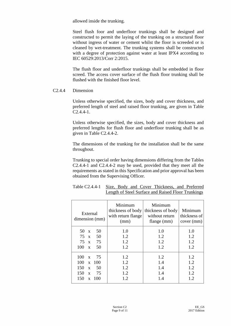
Section C2 Page 9 of 11
EE_GS 2017 Edition
allowed inside the trunking. Steel flush foor and underfloor trunkings shall be designed and constructed to permit the laying of the trunking on a structural floor without ingress of water or cement whilst the floor is screeded or is cleaned by wet-treatment. The trunking systems shall be constructed with a degree of protection against water at least IPX4 according to IEC 60529:2013/Corr 2:2015. The flush floor and underfloor trunkings shall be embedded in floor screed. The access cover surface of the flush floor trunking shall be flushed with the finished floor level.
C2.4.4 Dimension
Unless otherwise specified, the sizes, body and cover thickness, and preferred length of steel and raised floor trunking, are given in Table C2.4.4-1. Unless otherwise specified, the sizes, body and cover thickness and preferred lengths for flush floor and underfloor trunking shall be as given in Table C2.4.4-2. The dimensions of the trunking for the installation shall be the same throughout. Trunking to special order having dimensions differing from the Tables C2.4.4-1 and C2.4.4-2 may be used, provided that they meet all the requirements as stated in this Specification and prior approval has been obtained from the Supervising Officer.
Table C2.4.4-1 Size, Body and Cover Thickness, and Preferred
Length of Steel Surface and Raised Floor Trunkings
External dimension (mm)
Minimum thickness of body with return flange
(mm)
Minimum thickness of body
without return flange (mm)
Minimum thickness of cover (mm)
50 x 50 75 x 50 75 x 75
100 x 50
1.0 1.2 1.2 1.2
1.0 1.2 1.2 1.2
1.0 1.2 1.2 1.2
100 x 75 100 x 100 150 x 50 150 x 75 150 x 100
1.2 1.2 1.2 1.2 1.2
1.2 1.4 1.4 1.4 1.4
1.2 1.2 1.2 1.2 1.2
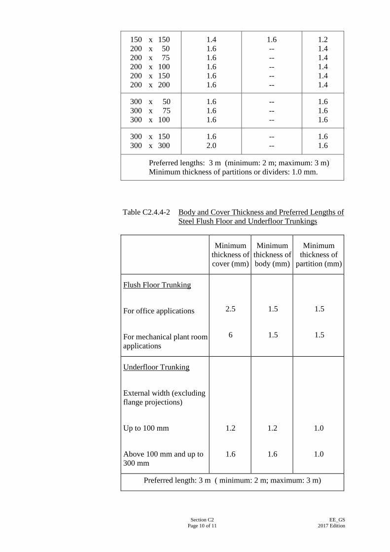
Section C2 Page 10 of 11
EE_GS 2017 Edition
150 x 150 200 x 50 200 x 75 200 x 100 200 x 150 200 x 200
1.4 1.6 1.6 1.6 1.6 1.6
1.6 -- -- -- -- --
1.2 1.4 1.4 1.4 1.4 1.4
300 x 50 300 x 75 300 x 100
1.6 1.6 1.6
-- -- --
1.6 1.6 1.6
300 x 150 300 x 300
1.6 2.0
-- --
1.6 1.6
Preferred lengths: 3 m (minimum: 2 m; maximum: 3 m) Minimum thickness of partitions or dividers: 1.0 mm.
Table C2.4.4-2 Body and Cover Thickness and Preferred Lengths of Steel Flush Floor and Underfloor Trunkings
Minimum thickness of cover (mm)
Minimum thickness of body (mm)
Minimum thickness of
partition (mm)
Flush Floor Trunking
For office applications
For mechanical plant room applications
2.5
6
1.5
1.5
1.5
1.5
Underfloor Trunking
External width (excluding flange projections)
Up to 100 mm
Above 100 mm and up to 300 mm
1.2
1.6
1.2
1.6
1.0
1.0
Preferred length: 3 m ( minimum: 2 m; maximum: 3 m)
Section C2 Page 11 of 11
EE_GS 2017 Edition
C2.4.5 Connection between Lengths of Trunking Connection between adjacent lengths of trunkings, tee or angle pieces, accessories, etc. shall be made by connectors. The two adjacent ends of trunking shall be fixed so that no relative movement can occur between them. Electrical continuity shall be achieved by means of connecting a continuity bonding link of adequate size across the two adjacent ends of the trunking. The continuity bonding link shall be of such materials to as to prevent electrolytic corrosion.
C2.4.6 Steel Surface Trunking Cover
Trunking and fittings shall have removable or hinged covers extending over the entire length. The covers shall be of the same material and finish as those of the trunking body. Removable covers shall be held in position on the trunking either by the natural elasticity of the material of the cover (e.g. spring capped trunking) or by other approved means which hold the covers tightly onto the trunking body and cause no damage to the cables inside. Bends, tee junctions, etc. shall also be fitted with removable or hinged covers of the same construction as that of the trunking.
C2.4.7 Screw
Screws used for securing a cover or connector and for fixing a trunking shall have ISO metric threads. They shall be of brass or steel. Steel screws shall be protected against corrosion by a finish at least equal to the zinc coating specified in BS 3382-2:1961. Electro-brass plated screws or self tapping screws shall NOT be used. Projection of screws inside a trunking or a trunking fitting will not be allowed.
C2.5 PLASTIC OR PVC TRUNKING AND ACCESSORIES
PVC trunking and fittings shall comply with IEC 61084-1:2007/Amd 1:1993. The nominal dimensions of PVC cable trunking shall be selected from any of the following numbers in mm: 12.5, 16.0, 20.0, 25.0, 32.0, 37.5, 40.0, 50.0, 75.0, 100.0 and 150.0 Cover for trunking shall be secured either by purpose-made rivets or clip-on mechanism to manufacturer’s standard.
Section C3 Page 1 of 7
EE_GS 2017 Edition
SECTION C3
POWER CABLES AND ASSOCIATED CABLING FACILITIES
C3.1 GENERAL
Power cables are mainly for electricity supply and distribution. They shall be manufactured under a recognised quality surveillance scheme (e.g. British Approvals Service for Cables (BASEC) licence or the HAR scheme recognised by the European Committee for Electrotechnical Standardization, CENELEC, etc.) and bear the appropriate marking (e.g. BASEC mark or HAR mark, etc.) of the quality surveillance scheme. Power cables shall have grading as specified in Clause C3.2 below. Cabling facilities will include cable ducts, cable trays and cable ladder.
C3.2 TYPES OF POWER CABLES
Power cables for supply and distribution shall be one or a combination of the following types as specified in the Particular Specification or on the Drawings: (a) 600/1,000 V cross-linked polyethylene (XLPE) insulated, single-core,
two-core, three-core or four-core, PVC sheathed with armour copper cables, with solid or stranded conductor, suitable for conductor operating temperature not exceeding 90oC – IEC 60502-1: 2004/Amd 1:2009;
(b) 600/1,000 V cross-linked polyethylene (XLPE) insulated, single-core,
two-core, three-core or four-core, sheathed with armour copper cable, with solid or stranded conductor, with low emission of smoke and corrosive gases when affected by fire, suitable for conductor operating temperature not exceeding 90oC – IEC60502-1: 2004/Amd 1:2009;
(c) 600/1,000 V fire resistant, cross-linked polyethylene (XLPE) insulated,
two-core, three-core or four-core, sheathed with armour copper cable, with solid or stranded conductor, with low emission of smoke and corrosive gases when affected by fire, suitable for conductor operating temperature not exceeding 90oC - Category F2 of BS 7846:2015. Fire resistant cable shall also comply with the fire performance requirement specified in Clause C2.1.6;
(d) 500 V (light duty grade) mineral insulated, single-core, two-core,
three-core or four-core, copper sheathed copper cable with – IEC 60702-1: 2002/Amd 1:2015 and IEC 60702-2:2002/Amd 1:2015;
(e) 750 V (heavy duty grade) mineral insulated, single-core, two-core,
three-core or four-core, copper sheathed copper cable – IEC 60702-1: 2002/Amd 1:2015 and IEC 60702-2:2002/Amd 1:2015; or
Section C3 Page 2 of 7
EE_GS 2017 Edition
(f) 600/1000 V PVC insulated, single-core, two-core, three-core or four-core, PVC sheathed with armour copper cables, with solid or stranded conductor, suitable for conductor operating temperature not exceeding 70oC – IEC 60502-1:2004/Amd 1:2009.
C3.3 CONDUCTOR The requirement of conductor as stated in Clause C2.1.5 shall apply.
C3.4 ARMOUR The armour shall be of galvanised steel wire for multi-core cables. Single core armoured cables shall be provided with non-ferrous armour. Use of steel armour for single core cable is not accepted.
C3.5 CABLE TERMINATIONS Cables shall be terminated in approved non-ferrous mechanical glands which comply with BS EN 62444:2013 complete with compression devices for securing the cable sheath. An armour clamp shall be required for bonding to metal sheaths. Where the cables are installed in entirely dry situations, the gland shall be designed with a compressible gasket or packing for securing the inner sheath and means of anchoring the armour. For cables installed wholly or partly in outdoor or damp conditions compressible sealing and clamping features shall be provided for securing the inner and outer sheaths and also the armour; barriers shall be incorporated to prevent the ingress of moisture.
C3.6 FIRE PERFORMANCE OF FIRE RESISTANT CABLES The requirements as stated in Clause C2.1.6 shall apply.
C3.7 IDENTIFICATION OF CORE Each core of a PVC or XLPE power cable shall be identified continuously throughout its entire length. For a mineral-insulated cable each core shall be identifiable at its termination by the application of sleeves or discs of appropriate colours as prescribed below. Identification sleeves shall comply with BS 3858:1992, Type 3, where appropriate and shall have temperature rating similar to that of the sealant. The identification shall take the form of appropriate colour or number codes in accordance with Table C3.7, or the relevant Specifications.
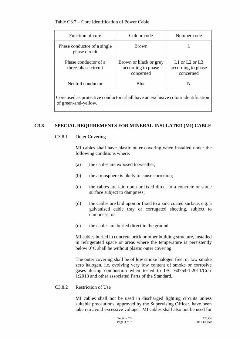
Section C3 Page 3 of 7
EE_GS 2017 Edition
Table C3.7 – Core Identification of Power Cable
Function of core Colour code Number code
Phase conductor of a single phase circuit
Brown L
Phase conductor of a three-phase circuit
Brown or black or grey according to phase
concerned
L1 or L2 or L3 according to phase
concerned
Neutral conductor Blue N
Core used as protective conductors shall have an exclusive colour identification of green-and-yellow.
C3.8 SPECIAL REQUIREMENTS FOR MINERAL INSULATED (MI) CABLE C3.8.1 Outer Covering
MI cables shall have plastic outer covering when installed under the following conditions where: (a) the cables are exposed to weather; (b) the atmosphere is likely to cause corrosion; (c) the cables are laid upon or fixed direct to a concrete or stone
surface subject to dampness; (d) the cables are laid upon or fixed to a zinc coated surface, e.g. a
galvanised cable tray or corrugated sheeting, subject to dampness; or
(e) the cables are buried direct in the ground. MI cables buried in concrete brick or other building structure, installed in refrigerated space or areas where the temperature is persistently below 0°C shall be without plastic outer covering. The outer covering shall be of low smoke halogen free, or low smoke zero halogen, i.e. evolving very low content of smoke or corrosive gases during combustion when tested to IEC 60754-1:2011/Corr 1:2013 and other associated Parts of the Standard.
C3.8.2 Restriction of Use
MI cables shall not be used in discharged lighting circuits unless suitable precautions, approved by the Supervising Officer, have been taken to avoid excessive voltage. MI cables shall also not be used for
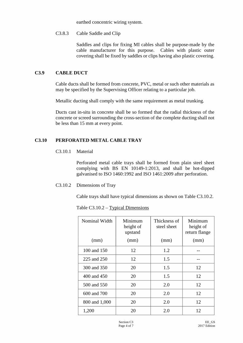
Section C3 Page 4 of 7
EE_GS 2017 Edition
earthed concentric wiring system.
C3.8.3 Cable Saddle and Clip Saddles and clips for fixing MI cables shall be purpose-made by the cable manufacturer for this purpose. Cables with plastic outer covering shall be fixed by saddles or clips having also plastic covering.
C3.9 CABLE DUCT Cable ducts shall be formed from concrete, PVC, metal or such other materials as may be specified by the Supervising Officer relating to a particular job. Metallic ducting shall comply with the same requirement as metal trunking. Ducts cast in-situ in concrete shall be so formed that the radial thickness of the concrete or screed surrounding the cross-section of the complete ducting shall not be less than 15 mm at every point.
C3.10 PERFORATED METAL CABLE TRAY C3.10.1 Material
Perforated metal cable trays shall be formed from plain steel sheet complying with BS EN 10149-1:2013, and shall be hot-dipped galvanised to ISO 1460:1992 and ISO 1461:2009 after perforation.
C3.10.2 Dimensions of Tray Cable trays shall have typical dimensions as shown on Table C3.10.2. Table C3.10.2 – Typical Dimensions
Nominal Width Minimum height of upstand
Thickness of steel sheet
Minimum height of
return flange (mm) (mm) (mm) (mm)
100 and 150 12 1.2 --
225 and 250 12 1.5 --
300 and 350 20 1.5 12
400 and 450 20 1.5 12
500 and 550 20 2.0 12
600 and 700 20 2.0 12
800 and 1,000 20 2.0 12
1,200 20 2.0 12
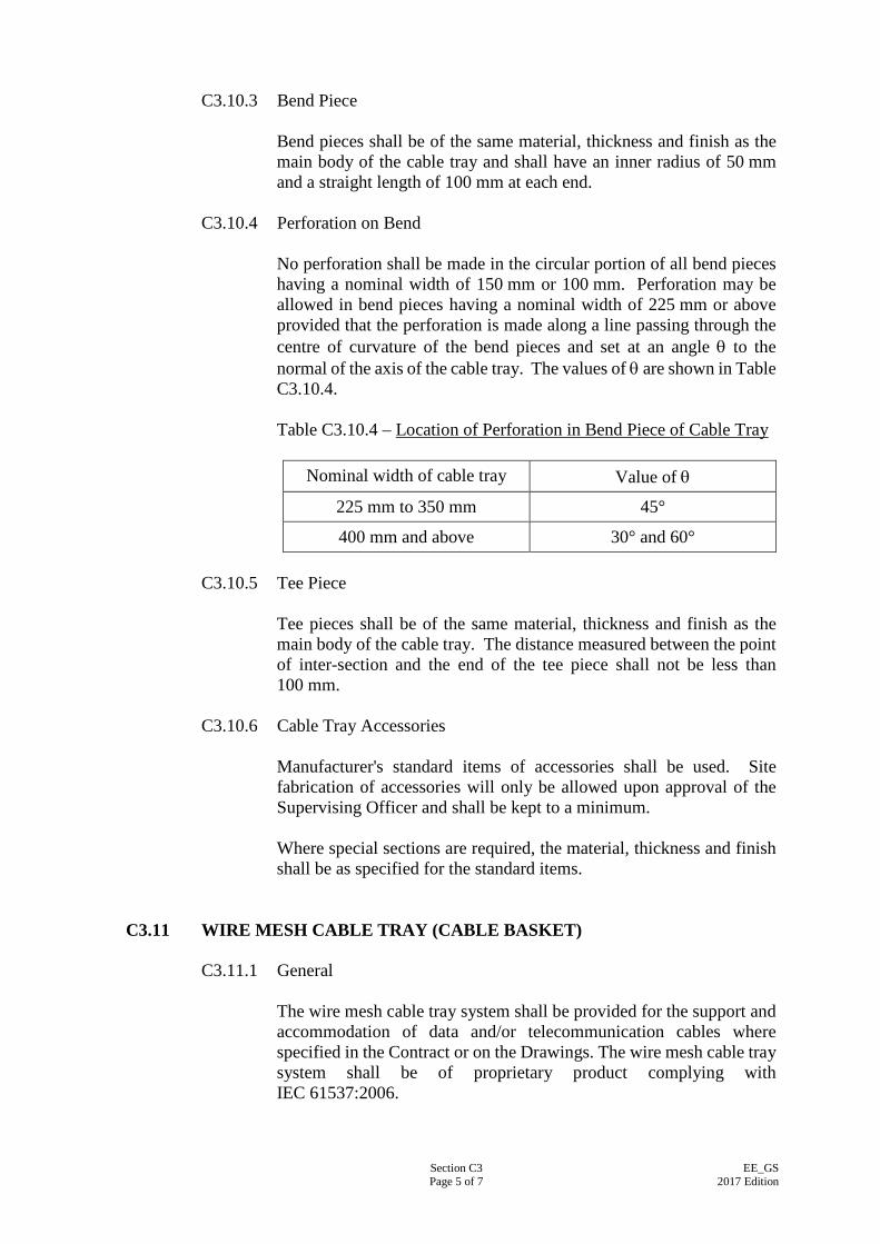
Section C3 Page 5 of 7
EE_GS 2017 Edition
C3.10.3 Bend Piece
Bend pieces shall be of the same material, thickness and finish as the main body of the cable tray and shall have an inner radius of 50 mm and a straight length of 100 mm at each end.
C3.10.4 Perforation on Bend No perforation shall be made in the circular portion of all bend pieces having a nominal width of 150 mm or 100 mm. Perforation may be allowed in bend pieces having a nominal width of 225 mm or above provided that the perforation is made along a line passing through the centre of curvature of the bend pieces and set at an angle θ to the normal of the axis of the cable tray. The values of θ are shown in Table C3.10.4. Table C3.10.4 – Location of Perforation in Bend Piece of Cable Tray
Nominal width of cable tray Value of θ
225 mm to 350 mm 45°
400 mm and above 30° and 60°
C3.10.5 Tee Piece Tee pieces shall be of the same material, thickness and finish as the main body of the cable tray. The distance measured between the point of inter-section and the end of the tee piece shall not be less than 100 mm.
C3.10.6 Cable Tray Accessories Manufacturer's standard items of accessories shall be used. Site fabrication of accessories will only be allowed upon approval of the Supervising Officer and shall be kept to a minimum. Where special sections are required, the material, thickness and finish shall be as specified for the standard items.
C3.11 WIRE MESH CABLE TRAY (CABLE BASKET) C3.11.1 General
The wire mesh cable tray system shall be provided for the support and accommodation of data and/or telecommunication cables where specified in the Contract or on the Drawings. The wire mesh cable tray system shall be of proprietary product complying with IEC 61537:2006.
Section C3 Page 6 of 7
EE_GS 2017 Edition
C3.11.2 Material Unless otherwise specified, the wire mesh cable tray shall be manufactured from steel wires and hot dipped galvanised to ISO 1461:2009 after formation of the cable tray.
C3.11.3 Fittings and Accessories All fittings and accessories associated with the installation of the wire mesh cable tray system shall be supplied by the same manufacturer with the same finish. All the accessories and tools for the connection of straight run pieces, formation of bends, risers, reducers, T-branch, etc. shall be provided by the manufacturer.
C3.11.4 Construction of Wire Mesh Cable Tray The steel wires of wire mesh cable trays shall be welded together and bent into rigid basket shape. The up-stand edges shall have a minimum height 50 mm to contain the cables. The surface of all system components, which come into contact with cables, shall not cause damage to the cables when installed according to the manufacturer’s recommendation.
C3.12 CABLE LADDER C3.12.1 Material
Generally, unless otherwise specified, all cable ladder fittings and accessories mentioned below shall be manufactured from hot rolled steel to BS EN 10149-1:2013 and then hot dipped galvanised to ISO 1460:1992 and ISO 1461:2009 after fabrication. For heavily corrosive environments where specified in the Contract, Specification or on the Drawings, cable ladder fittings and accessories shall be manufactured from stainless steel 316S31 to ISO 683-13:1986.
C3.12.2 Fittings and Accessories All fittings and accessories applied to the same cable ladder system shall be supplied by the same manufacturer to the same finish. In addition to straight ladders, the standard product range of the same cable ladder system shall at least include 90° bends, equal tees, four-way crossovers, 45° internal risers, 45° external risers, 90° internal risers, 90° external risers, straight reducers, left-hand offset reducers, right-hand offset reducers, various jointing couplers, various supporting brackets and hangers, various connectors, and various bolt and nuts.
Section C3 Page 7 of 7
EE_GS 2017 Edition
C3.12.3 Construction of Cable Ladder Cable ladder shall be of “heavy duty” type. The two rails shall be 90 mm minimum in height with top and bottom flanges of sufficient strength. The rungs shall be spaced at 300 mm centres maximum and shall have slots for cable fixing. The working depth (depth between top edge of rail and top surface of rung) shall be 60 mm minimum.
Section C4 Page 1 of 9
EE_GS 2017 Edition
SECTION C4
WIRING ACCESSORIES AND MEASURING INSTRUMENTS
C4.1 WIRING ACCESSORIES - GENERAL Wiring accessories shall meet the general requirements of BS 5733:2010/A1:2014. Unless otherwise specified, they shall be white or ivory in colour, uniform in colour and appearance throughout an installation. Moulded box or pattress and steel or cast iron box for the enclosure of wiring accessories shall comply with IEC 60670-1:2015 and other associated Parts of the Standard and shall meet the requirements specified in this Section and Sections B2, B4 & C2 of this Specification where appropriate.
C4.2 DOMESTIC SWITCHES C4.2.1 General
Switch for domestic and similar purposes shall comply with IEC 60669-1INTI:2012. Switch mounted outdoor, or in positions where it may be exposed to rain or water, shall be of watertight construction with minimum IP54 protection in accordance with IEC 60529:2013/Corr 2:2015.
C4.2.2 Lighting Switch
Lighting switch shall be suitable for use in AC circuits, and shall be of the quick make-and-break type when used in DC circuits. The front plate shall be of plastic insulating material. Suspension pear type switches shall not be used. Lighting switch shall be single pole of rated fluorescent load not less than 5 AX or 10 AX as specified in the Particular Specification or Drawings.
C4.2.3 Double Pole Switch for Appliance
Double pole switch shall be integrated with a pilot light formed by a neon lamp with a resistor and a red coloured lens.
C4.2.4 Sparkless Switch
Sparkless switch shall be of the tilting mercury type. The contacts of a sparkless switch shall be contained in a sealed glass capsule.
C4.2.5 Time Switch
Time switch shall be designed for 7 days, 24-hour operation and shall
Section C4 Page 2 of 9
EE_GS 2017 Edition
be driven by a quartz oscillator synchronous motor or an electronic operated clock. Time setting shall be accomplished by plugging in setting pins and a minimum setting period of 15 minutes shall be achievable. All component parts shall be of robust design, constructed from durable materials and capable of maintaining proper functions and high accuracy and not subject to easy wear and tear during normal operation. The whole unit shall be encompassed in a metal or moulded box with ingress protection not less than IP53 to IEC 60529:2013/Corr 2:2015. The box shall be suitable for wall mounting and entry of a 20 mm conduit. An inspection glass window and quick action fastener shall be fitted on the front lid of the box. Time switch shall incorporate the following features: (a) The clock shall be of direct reading type with minute adjustable
knob to set time precisely to the minute. Accuracy of the clock shall be within ± 15 sec per month;
(b) A “long life” cassette type alkaline battery back-up device shall
be incorporated to provide 360 hours continuous operation upon power failure;
(c) The switch shall consists of single pole, single throw silver
contacts capable of accommodating a minimum load of 20 A at 250 V AC resistive, 7.5 A inductive at 0.7 power factor or 10 A incandescent lamps. The contacts shall be capable of being isolated for external circuit connection;
(d) A changeover switch shall be provided for selecting the
ON/AUTO/OFF mode of operation; and (e) Rated power consumption of the whole unit shall not exceed
2.5 W.
C4.3 SOCKET OUTLETS
C4.3.1 General
All socket outlets shall be of 3-pin shuttered type. Socket outlet and plug rated at 13 A shall comply with BS 1363-2:1995/A4:2012. Socket outlet and plug rated at 5 A or 15 A for general application shall comply with BS 546:1950. Weatherproof socket outlet shall have cover with ingress protection of at least IP55 to IEC 60529:2013/Corr 2:2015. For socket outlet installed at outdoor or exposed to sunlight, the cover of the socket shall be UV stabilised, chemically and impact resistant with ingress protection at least IP66. Socket outlet used for supplying appliance mounted at high level shall be unswitched, otherwise it shall be fitted with an integral switch. The integral switch shall be of double pole, forming part of the same front plate as the socket outlet, and with clear indication of the ON/OFF switching position.
Section C4 Page 3 of 9
EE_GS 2017 Edition
Industrial type socket outlet shall comply with IEC 60309-2:2012 and be provided with a push-on cap and cap retaining ring or a screw-on cap with rubber gasket. The socket outlet shall have ingress protection of at least IPX4 to IEC 60529:2013/Corr 2:2015.
C4.3.2 Shaver Supply Unit
Electric shaver supply unit shall comply with IEC 61558-1:2009/Corr 3:2011 and shall be all insulated, suitable for both flush and surface mounting. Each unit shall comprise two outlets, one for 110 V and the other for 220 V, obtained from tappings of a double wound transformer to IEC 61558-2-5:2010 and with unearthed secondary windings.
C4.3.3 Plug Unless otherwise specified, plug for 13 A socket outlet shall be fitted with a fuse to BS 1363-2:1995/A4:2012, rated at 13 A. Each plug shall be fitted with a cord grip which is so designed that no stress will be exerted on the conductors of the flexible cable connected to it at the terminals.
C4.4 CONNECTION UNITS C4.4.1 (NOT USED)
C4.4.2 Switched or Unswitched Fused Connection Unit
The connection unit is intended for final connection to a fixed equipment or appliance which has a full load current not exceeding 13 A. It shall be of double pole type with neon/LED indicator meeting the requirements of BS 1363-4:1995. It shall incorporate a fuse link to BS 1363-2:1995 rated to suit the appliance to be connected in the pole connecting to the phase conductor. An earth terminal shall also be provided for the connection of the circuit protective conductor to the appliance.
C4.5 INSULATED TERMINAL BLOCK The rated voltage of a terminal block shall not be less than 435 V between terminals and 250 V to earth. Terminal block shall comprise copper connectors with screw connections, all contained within a moulded block suitable for working temperature up to 100°C. Terminals shall be designed to clamp the conductors to the metal surface with sufficient contact pressure but without damaging the conductors. With the largest recommended conductor in position, and tightly clamped, there shall be at least two full threads of the screw engaging in the connector.
Section C4 Page 4 of 9
EE_GS 2017 Edition
C4.6 LIGHTING SYSTEM ACCESSORIES C4.6.1 Luminaire Track System
Luminaire track system shall comply with IEC 60570:2003. It shall be designed for ordinary interior use for mounting on, or suspended from wall or ceiling. The track shall be of two or four-pole with provision for earthing, with a rated voltage not exceeding 250 V AC to earth and a rated current not exceeding 32 A per conductor for distribution to luminaires.
C4.6.2 Photocell Device
Photocell device shall comply with BS 667:2005 and shall have good tolerances in physical dimensions and with no moving parts. An additional circuitry shall be provided to achieve a delay of at least 30 seconds so as to eliminate switching due to lightning or other short period changes in illumination.
C4.6.3 Ceiling Rose
Ceiling rose of maximum rating of 6 A at 250 V shall comply with BS 67:1987 and shall be ivory or white moulding with outside diameter not less than 63 mm and 50.8 mm fixing centres, 3-plate pillar type with earth terminal and with integral cord-grip.
C4.6.4 Lampholder
Batten lampholder shall be of bayonet type complying with IEC 61184:2011/Corr 2:2012 or Edison screw type complying with IEC 60238:2011. The lampholder shall be manufactured from moulded hard white or ivory colour plastic material which shall be unaffected by the heat from the lamp. Lampholder for weatherproof luminaire shall be porcelain and comply with IEC 61184:2009. Lampholder for use with tubular fluorescent lamp shall be of bi-pin type, complying with IEC 61184:2009, IEC 60061-1:2005/Amd 53:2015 and IEC 60061-2:2005/Amd 50:2015. It shall be made of moulded white plastic material and designed to hold the tube in position without the need for additional clip.
C4.7 MEASURING INSTRUMENT C4.7.1 Watt-hour Meter
Watt-hour meter shall comply with IEC 62053-11:2003. The register shall be of drum type and the principal unit in which the register records shall be in kilowatt-hours (kWh). The casing shall be of black phenolic moulding with an inspection glass window.
Section C4 Page 5 of 9
EE_GS 2017 Edition
Watt-hour meter shall have Class 2 accuracy calibrated at the normal working voltage and frequency.
C4.7.2 Ammeter and Voltmeter
Ammeter and voltmeter shall be of moving iron type, moving magnet type or moving coil with transducer type complying with the relevant parts of IEC 60051 series (including IEC60051-1:1997 to IEC 60051-9:1988/ADM2: 1995). The accuracy class shall be "2.5" or better in accordance with the relevant parts of IEC 60051 series. The dial of ammeter and voltmeter shall have a nominal diameter of 100 mm and shall have a scale deflection not less than 90°. The operating voltage and running current of the connected circuit shall be clearly indicated on the voltmeter and ammeter respectively. An ammeter for any circuit of rating up to 60 A may be connected directly in series with the circuit, so that the full circuit current passes through the instrument. For a circuit of rating exceeding 60 A, the ammeter shall be fed through the secondary winding of a current transformer, and shall give a full scale deflection with a secondary current of 5 A.
C4.7.3 Current Transformer
Current transformer for use with measuring instrument shall comply with IEC 61869-2:2012 having rated secondary current of 5 A and rated output suitably matched with the loading of the measuring instrument. The accuracy class shall be "1" in accordance with IEC 60044-1:2003.
C4.7.4 Selector Switch for Ammeter
Where a single ammeter is used to measure the current in each phase or the neutral of a three phase circuit, the ammeter shall be connected to a selector switch which shall enable the ammeter to be inserted in series with each phase and the neutral in turn. When the ammeter is connected to the secondary windings of the measuring current transformers, the selector switch shall have facilities to prevent the current transformers from being open circuited during change-over and at "OFF" position.
C4.7.5 Selector Switch for Voltmeter
In a three phase circuit in which a single voltmeter is used to measure the various voltages, the voltmeter shall be provided with a selector switch to enable the following voltages to be measured: (a) voltage between each phase to neutral; and
(b) voltage between any two phases.
The selector switch shall also have an "OFF" position.
Section C4 Page 6 of 9
EE_GS 2017 Edition
C4.7.6 Meter Chamber
Meter chamber for housing watt-hour meter shall be made from galvanised steel of not less than 1.6 mm thick and shall be of ample size to accommodate the required number of watt-hour meters and meter cables. Provision shall be made to enable the watt-hour meters to be fixed inside the chamber without removing the chamber from the wall or other supports. Meter fixing screws shall not project through the back of the chamber. When a meter chamber is installed indoor, it shall be fitted with a hinged metal front cover. Meter chamber installed outdoor shall be waterproof, with screw-on type front cover. The ingress protection for the outdoor type shall be at least IP54 in accordance with IEC 60529:2013/Corr 2:2015. A glass window of adequate size shall be provided on the front cover of the meter chamber to enable the registers and serial numbers of the watt-hour meters to be read easily.
C4.8 OCCUPANCY AND DAYLIGHT SENSOR
C4.8.1 General The sensor shall be suitable to operate under the following conditions: Operating voltage: : 12 – 36 V DC or 220 V ± 6% AC Operating environment: : Temperature : 0°C – 40°C indoor,
: Relative humidity: less than 95% non- condensing
Where the computerized lighting management system is specified, the sensor shall be capable of networking and integrating into the system. Where the control of air conditioning units by the sensors is specified, the sensors shall be capable to control the designated air conditioning units as required to meet the contract requirements. For standalone application, the occupancy sensor shall be capable of controlling the lighting circuit connected for direct on/off switching or dimming performance.
C4.8.2 Passive Infrared (PIR) sensor
(a) PIR sensor shall detect occupancy in the control area by sensing the difference between heat emission from human body in motion and the background space.
(b) The PIR sensor shall be provided with built-in heat sensing
detector resided behind an optical lens.
Section C4 Page 7 of 9
EE_GS 2017 Edition
(c) The PIR sensor shall have 360o field of view with provision of mounting external covering mask for fine adjustment of the detection zone to meet the various applications.
(d) When the sensor is mounted under the ceiling at 2.4 m above
the finished floor level, the minimum detection coverage area shall not be less than 5 m in diameter.
(e) A built-in LED lamp shall be provided and illuminated once the
sensor detects movement within the control area. (f) Sensing sensitivity and extent of detection area shall be
adjustable in field. (g) The sensor shall be provided with its own delay timer for
adjusting the delay of switching off the lights between 5 seconds to 20 minutes when no occupancy being sensed.
C4.8.3 Ultrasonic sensor
(a) Ultrasonic sensor shall detect occupancy by sensing frequency shift between the emitted ultrasonic wave (normally in the range of 32 -40 kHz) and the reflected wave in the controlled space.
(b) The sensor shall comprise one or two pairs of ultrasonic
transducers as specified. For each pair of transducers, one transducer shall be used for emitting while the other one for receiving signal.
(c) The sensor shall have either 180° or 360° field of view to meet
the application need. (d) Sensing sensitivity and extent of detection area shall be
adjustable in field. (e) The sensor shall be provided with its own delay timer for
adjusting the delay of switching off the lights between 5 seconds to 20 minutes when no occupancy being sensed.
(f) When the sensor is mounted under the ceiling at 2.4 m above
the floor level, the minimum area of coverage shall not be less than 40 m2 under the 360° field of view.
(g) LED shall be provided with the sensor to indicate motion being
detected. (h) Air current (airflow) compensation device shall be provided for
sensitivity adjustment.
Section C4 Page 8 of 9
EE_GS 2017 Edition
C4.8.4 Dual Technology sensor
(a) Dual technology occupancy sensor shall use both passive infrared heat change and frequency shifts in ultrasonic wave to detect occupancy.
(b) The sensor shall comprise one or two pairs of ultrasonic
transducers and one PIR sensing detector. For each pair of ultrasonic transducers, one transducer shall be used for emitting while the other one for receiving signal.
(c) Ultrasonic detection and PIR detection shall be independently
enabled/disabled to suit the application. (d) Sensing sensitivity and extent of detection area shall be
adjustable in field. (e) Switching on the lighting associated with the occupancy sensor
shall be triggered either by ultrasonic or PIR signal or both. (f) The sensor shall be provided with its own delay timer for
adjusting the delay of switching off the lights between 5 seconds to 20 minutes when no occupancy being sensed.
(g) The ultrasonic sensor shall have either 180o or 360o field of
vision to meet the application need. The PIR sensor shall have 360o field of view with provision of mounting external covering mask for fine adjustment of the detection zone to meet the various applications.
(h) The minimum area coverage shall not be less than 40 m2 when
the sensor is mounted under the ceiling at 2.4 m above the floor level under the 360° field of view.
(i) Two LEDs shall be provided with the sensor, one to indicate the
detection of movement by PIR and another for movement indication by ultrasonic.
(j) Air current (airflow) compensation device shall be provided for
sensitivity adjustment.
C4.8.5 Daylight sensor
(a) Daylight sensor is used to measure and monitor the ambient light level for switching on/off or dimming the interior lighting fittings to maintain the setting illuminance in a given area. The daylight sensor shall connect to the computerized lighting management system to perform the dimming function.
(b) The daylight sensor shall has a dynamic light level measuring
ranging 50 -1,000 lux.
Section C4 Page 9 of 9
EE_GS 2017 Edition
(c) The preset light level and its deadband range of maintaining the preset light level of daylight sensor shall be able to be adjusted through the computerized lighting management system. If the light level stays within the deadband, the light level at the controlled area shall remain at preset level.
(d) Device shall be incorporated to compensate rapid light intensity
fluctuations.
Section C5 Page 1 of 64
EE_GS 2017 Edition
SECTION C5
SWITCHGEAR AND ASSOCIATED EQUIPMENT
C5.1 GENERAL
C5.1.1 Scope This Section specifies the general requirements of switchgear and associated equipment operating at low voltages, which may be assembled on site from individual items of components. The switchgear and associated equipment shall be manufactured to the relevant current International Electrotechnical Commission (IEC) Standards as indicated below: IEC 60947-1:2014 : Low-voltage switchgear and controlgear – Part 1:
General rules IEC 61439-1:2011 : Low-voltage switchgear and controlgear
assemblies – Part 1: General rules IEC 61439-2:2011 : Low-voltage switchgear and controlgear
assemblies – Part 2: Power switchgear and controlgear assemblies
IEC 61439-3:2012/Corr 1:2013 : Low-voltage switchgear and controlgear assemblies – Part 3: Distribution boards intended to be operated by ordinary persons (DBO) Other requirements as specified in Clauses C5.1.2 to C5.1.8, both inclusive, shall also apply to all items of switchgear and associated equipment where applicable unless explicitly mentioned elsewhere. Additional and specific requirements for verification test of low-voltage switchgear and controlgear assemblies as described in IEC 61439-1:2011 and IEC 61439-2:2011 shall be given in Section C11 of this Specification, the Particular Specifications, the Drawings and other documents issued by the Supervising Officer. The component equipment covered in this Section shall include the following: (a) Switches, disconnectors (isolators), fuse-switches and
switch-fuses; (b) Circuit-breakers including air circuit-breakers (ACB), moulded
case circuit-breakers (MCCB), miniature circuit-breakers (MCB), residual current-operated circuit breakers without integral overcurrent protection (RCCB) and residual
Section C5 Page 2 of 64
EE_GS 2017 Edition
current-operated circuit breakers with integral overcurrent protection (RCBO);
(c) Fuses; (d) Busbar chambers and distribution boards; and (e) Electromechanical contactors, motor starters and automatic
changeover switches. C5.1.2 Service Condition
The following service conditions shall apply: (a) Ambient temperature - peak from minus 5°C to plus 40°C for
4-hours continuously with an average from 0°C to plus 35°C over only 24 hours period;
(b) Altitude - up to 2,000 m above sea level; (c) Relative humidity - up to 99% or non-condensing; (d) Pollution Degree 3 - Conductive pollution occurs, or dry,
non-conductive pollution occurs which becomes conductive due to condensation; and
(e) Climatic condition – Tropical (Hong Kong).
C5.1.3 Short-circuit Rating and Continuous Current Rating
Switchgear shall be suitably rated for the specified prospective short-circuit current which can occur at the point of its installation. It shall also be rated for uninterrupted duty when carrying continuously the specified full load current. For non-automatic switching devices, the rated short-time withstanding current shall be at least 12 times of the maximum rated operational current for 1 second. Where equipment components are installed in enclosures, they shall be suitable for operation at the actual maximum temperatures which will be reached within the enclosures under normal loaded conditions when the ambient temperature is 40°C.
C5.1.4 Voltage Rating Same as specified in Clause C1.2.
C5.1.5 Degree of Protection for Enclosure
Enclosures for switchgear and associated equipment shall be of totally enclosed type. For indoor applications, the enclosure shall have an ingress protection (IP), in accordance with IEC 60529:2013/Corr 2:2015, of at least IP41 for the top surface and IP31 for the other
Section C5 Page 3 of 64
EE_GS 2017 Edition
surfaces of the enclosure. For outdoor applications, the enclosure shall be of at least IP54.
C5.1.6 Material
Unless otherwise specified, switchgear and associated equipment except MCCB and MCB shall be of metalclad. All ferrous metal parts shall be galvanised or chrome plated unless the final finish has been painted or enamelled in the manufacturer's factory. All extraneous conductive parts shall be electrically continuous.
C5.1.7 ON and OFF Indication
The design of a switching device shall incorporate positive means to indicate clearly and reliably the ON (or CLOSE) and the OFF (or OPEN) positions of the contacts. Indication of either position shall only occur when the ON or OFF position on every pole has been attained. Such indication shall be provided on the outside of the device and shall be prominently visible to an operator when the device is installed in the normal manner. When the switching device is also used for isolation purpose, then an indication of the OFF position shall occur only when all contacts are also in the OFF position and the isolating distance between contacts in every pole has attained a clearance not less than those specified for disconnectors according to IEC 60947-3:2015.
C5.1.8 Identification of Circuit
Labels or other means of identification shall be provided for every item of switchgear and associated equipment to indicate the purpose of the item. The labels shall either be fixed at the front cover of the equipment or at the inside surface of the hinged front cover.
C5.2 SWITCH, DISCONNECTOR, FUSE-SWITCH AND SWITCH-FUSE
C5.2.1 Scope of Switch
All reference to switches in this and subsequent Clauses shall include also fuse-switches or switch-fuses.
C5.2.2 General
Switches, disconnectors, fuse-switches and switch-fuses shall comply with and be tested to IEC 60947-3:2015 and shall have air-break type contacts which are designed for uninterrupted duties. They shall be either three pole with switched neutral (four-pole), triple-pole with neutral link, double-pole, or single pole with neutral link as specified, and shall each be fitted with earthing facilities. All live parts shall be efficiently shrouded with insulating materials. Cam switches or
Section C5 Page 4 of 64
EE_GS 2017 Edition
disconnectors shall not be used for circuits of 50 A or above. Each switch shall be supplied in complete unit consisting of a basic unit contained within an enclosure. Adequate space shall be provided in the enclosure for proper cable termination, otherwise cable boxes shall be provided. Fuse carriers, when required, shall be included.
C5.2.3 Operating Mechanism
Switches and disconnectors shall be of the quick-make and quick break type. The switching mechanism shall be of independent manual operation with suitable means such as accelerating springs. For switches and isolators with switched neutral, the neutral pole shall open after the phase pole contacts and shall close before or at the same time as the phase pole contacts.
C5.2.4 Construction
The enclosure shall be of totally enclosed type, made up of heavy gauge sheet metal, adequately rust and dust protected, and finished in enamel. An earthing terminal shall be provided. The enclosure shall be suitable for conduit, trunking and armoured cable entries and also for connection to busbar chamber from top or bottom. Frame sizes for the range of switches shall be kept to a minimum. Switches and isolators shall be constructed with an interlocked front cover to prevent access to the interior parts of the equipment when the contacts are in the CLOSE position, and to prevent the contacts from being switched to close when the front cover is opened. However, facilities shall be provided to allow the checking of the contact alignments. The fastening devices for the front cover shall be of captive type. Insulation material used shall be of non-hygroscopic and non-ignitable type. The contacts shall be self-aligning so that contact pressure can be maintained at all times. All live parts shall be adequately shielded from the front of the unit but easily accessible for maintenance by using a tool.
C5.2.5 Operating Performance
The operating performance of the switches and disconnectors shall be tested in accordance with IEC 60947-3:2015. The number of operating cycles corresponding to the rated operational current shall not be less than the values given in Table 4 of IEC 60947-3:2008.
C5.2.6 Utilisation Category
Switches shall be to utilisation categories of AC-22 A or AC-22B for general applications and AC-23 A or AC-23B for electrical motor circuits; unless otherwise specified.
Section C5 Page 5 of 64
EE_GS 2017 Edition
C5.2.7 Padlocking Facility
Switches and disconnectors shall be fitted with padlocking facilities so that they can be padlocked in either ON or OFF position.
C5.3 CIRCUIT BREAKER - GENERAL
C5.3.1 Scope of Circuit Breaker
This Clause covers the general requirements of ACB, MCCB, MCB, and RCCB and RCBO. Additional requirements relevant to a particular type of circuit breakers shall be given in Clauses C5.4 to C5.7, both inclusive.
C5.3.2 Number of Poles
Circuit breakers shall be of triple-pole with switched neutral (four-pole), three-pole, double-pole or single-pole, as specified, and shall have air-break contacts. All poles, except the neutral poles, shall be designed to have their contacts open or close simultaneously.
C5.3.3 Operating Mechanism
The operating mechanism of a circuit breaker shall be trip-free. When a MCCB, MCB, RCCB or RCBO trips and opens its contacts, the operating toggle shall automatically resume the OFF or TRIPPED position.
C5.3.4 Casing
The casing of an ACB shall be metalclad. The casing of a MCCB, MCB, RCCB or RCBO shall be formed from insulating material. The construction shall be capable of withstanding the appropriate rated short circuit current and reasonably rough use without fracture or distortion.
C5.3.5 Current Rating
The rated current of a circuit breaker shall be taken as that rated continuous current when the circuit breaker is installed in the enclosure together with other equipment if any under normal operating conditions as specified in the Particular Specification.
C5.4 AIR CIRCUIT BREAKER (ACB)
C5.4.1 General
Section C5 Page 6 of 64
EE_GS 2017 Edition
All circuit breakers shall not be of moulded case type. The neutral pole shall have cross-sectional areas not less than that of respective phase pole. ACB shall be of triple-pole with switched neutral (four pole) or triple-pole with bolted neutral, as specified, fully metalclad with earth terminals. It shall be of horizontally withdrawable type having spring assisted closing and, where specified, motorised spring charger and push-button electrical control. ACB shall comply with and be type tested to IEC 60947-2:2013. Unless otherwise specified, ACB shall have built-in overload protection with IDMT characteristics and instantaneous short circuit interruption. Where an ACB is used as the main incomer, the IDMT characteristics shall be compatible with those of the Electricity Supplier.
C5.4.2 Performance Characteristic
ACB shall be certified, in accordance with IEC 60947-2:2013, to have the following performance characteristics: (a) Rated short-circuit breaking capacity - not less than 50 kA; (b) Rated short-circuit making capacity - not less than 105 kA; and (c) Rated short-time withstanding current - not less than 50 kA for
1 second.
C5.4.3 Closing and Tripping Operation
Unless otherwise specified, ACB shall be suitable for independent manual operation utilising energy stored in a spring. For automatic closing ACB, the spring mechanism shall be wound by a universal motor fitted with limiting switches. In addition, the spring mechanism shall have manual charging facilities for emergency use. Unless otherwise specified, trip coil of 24 V or 30 V DC shall be fitted for local, remote or relay tripping. "Trip" push buttons shall be provided on the front plate of each ACB. These buttons shall be direct acting mechanically. When automatic closing is specified, the control circuit of the ACB shall be fitted with suitable anti-pumping devices.
C5.4.4 Racking Gear
The enclosure shall be fitted with a set of racking gear which shall lock the ACB to the runner rails in three distinct positions, i.e. CONNECTED, TEST and ISOLATED. The ACB can only be closed
Section C5 Page 7 of 64
EE_GS 2017 Edition
fully when it is in the CONNECTED position. In the TEST position, it shall be possible to operate the ACB to close and test the secondary and auxiliary contacts, but not the main isolating contacts. The racking gear shall consist of rollers fitted to the ACB frame. All parts shall be accurately aligned and adjusted so that the ACB can be moved freely along the runner rails within the enclosure between the two extreme positions, i.e. CONNECTED and ISOLATED. Facilities shall be provided to padlock the ACB in its CONNECTED, TEST or ISOLATED position. Position indicators and breaker-condition indicators shall be provided. These indicators shall be arranged so as to be prominently visible when the ACB is in its normally installed position.
C5.4.5 Interlocking Facility
Suitable interlocking facilities shall be provided such that: (a) the ACB cannot be plugged in or withdrawn when it has been
closed; (b) the ACB cannot be closed until it is fully engaged in either the
CONNECTED or the TEST position; (c) the ACB cannot be slowly closed except in the TEST or
ISOLATED position; (d) it shall not be possible to initiate the closing action of the energy
stored spring mechanism until the spring has been fully charged; and
(e) Where key interlocking is employed, tripping of a closed ACB
shall occur if an attempt is made to remove the trapped key from the mechanism.
C5.4.6 Main Isolating Contacts and Safety Shutter
The main isolating contacts shall be self-aligning and shall be protected by insulated barriers forming the safety shutter. 2 sets of safety shutters shall be provided for every ACB, one for the incoming terminals of the main isolating contacts and the other for the outgoing terminals. Each set shall be capable of being operated individually. When the ACB is not in the CONNECTED position, the safety shutters shall close automatically, screening off the main isolating contacts. When the ACB is being racked into the CONNECTED position, the safety shutters shall automatically open the insulating barrier, thereby allowing the entry of the movable isolating contacts but without lowering the degree of protection.
Section C5 Page 8 of 64
EE_GS 2017 Edition
Safety shutters shall be fitted with properly designed and securely fixed warning labels. In addition, facilities shall be provided to padlock the safety shutters after the ACB has been withdrawn from the enclosure.
C5.4.7 Contact
All contacts shall be self-aligning, provided with spring accelerated opening mechanism. Main contacts shall be fitted with detachable arc chutes for each pole. Sufficient auxiliary contacts shall be provided for connection of secondary wiring. These auxiliary contacts shall remain engaged when the ACB is in the TEST or CONNECTED position and shall be disengaged when the ACB is in the ISOLATED position. All ACB shall be fitted with the maximum number of auxiliary contacts as the manufacturer's standard provision. In any event, not less than two pairs of normally-closed auxiliary switches and two pairs of normally-open auxiliary switches shall be provided. All auxiliary contacts and switches shall be wired to an easily accessible terminal strip for external connection. Terminals for external connections of the secondary/auxiliary contacts and switches shall be of clamping yoke type for wires of minimum CSA of 1.0 mm². All terminals shall be clearly labelled to identify the function of the circuits connected to the terminals. Terminals for each ACB for secondary/auxiliary contacts shall be separated from all other terminals by means of a spacer of 20 mm width.
C5.5 MOULDED CASE CIRCUIT BREAKER (MCCB)
C5.5.1 General
MCCB shall be of four-pole, triple-pole or double-pole as specified. It shall comply with and be type-tested to IEC 60947-2:2013. It shall be totally enclosed in a moulded casing formed from an insulating material. The construction of the casing shall be capable of withstanding the appropriate rated short circuit current and reasonably rough use without fracture or distortion. The moulded casing shall have an ingress of protection not less than IP30. Utilisation category for those MCCB with built-in protection and rated at 400 A or above shall be class B, unless otherwise specified in the Particular Specification or on Drawings or the EE Contractor can substantiate with calculations to the satisfaction of the Supervising Officer that class A MCCBs are suitable for ensuring discrimination under overload and short circuit conditions for the circuits concerned.

Section C5 Page 9 of 64
EE_GS 2017 Edition
MCCB shall incorporate overcurrent and earth fault protection as specified with shunt trip coil operated by protection relays, and shall be suitable for use as an isolator.
C5.5.2 Operating Characteristic
MCCB with built-in protection shall have thermal-magnetic or solid state tripping device which features a fixed, stable, inverse time-current characteristic. The operating characteristic shall be such that: (a) the time delay on overload tripping shall be inversely
proportional to the overcurrents up to a threshold value of approximately 7 times the rated current; and
(b) there shall be no intentional time-delay on overcurrent tripping
due to short-circuit or heavy overcurrent exceeding the threshold value (i.e. approximately 7 times the rated current).
The operating characteristics shall be calibrated at 40°C. When MCCB is specified to be completed with earth leakage tripping device, the tripping current shall be as specified in the Particular Specification or on the Drawings. The earth leakage relay and the zero-sequence current transformer, if any, shall comply with the IEC 60255-1:2009, IEC TR 60755:2008 and IEC 61869-2:2012 respectively.
C5.5.3 Performance Characteristic
MCCB shall be certified, according to IEC 60947-2:2013, to have the following performance characteristics: Rated short circuit breaking capacity - not less than the values given in the Table C5.5.3. Table C5.5.3 - Rated Short Circuit Breaking Capacity of MCCB
Frame size
Tested short-circuit breaking capacity Tested at power factor of:
100 A 23 kA not exceeding 0.30 lagging 225 A 23 kA not exceeding 0.25 lagging 400 A 23 kA not exceeding 0.25 lagging
> 400 A 40 kA not exceeding 0.25 lagging
C5.5.4 Shunt Trip Release
Where shunt trip release is specified, this shall operate correctly at all values of supply voltage between 70% and 110% of the nominal supply voltage under all operating conditions of the MCCB up to the
Section C5 Page 10 of 64
EE_GS 2017 Edition
rated short-circuit breaking capacity of this MCCB. MCCB incorporating shunt release shall be provided with block terminals and shunt release lead cables.
C5.5.5 Locking Facility MCCB shall be provided with facility for padlocking in either the "ON" or "OFF" position.
C5.6 MINIATURE CIRCUIT BREAKER (MCB)
C5.6.1 General
MCB shall be of four-pole, triple-pole, double-pole or single-pole as specified. It shall comply with and be type tested to IEC 60898-1:2003. It shall be totally enclosed in a moulded insulating case and lockable for safe use and also designed to be maintenance free. Overall dimensions and fixing centres for the same range of MCB shall be identical and suitable for fixing individually to a metal back plate or directly mounted inside a manufacturer's designed distribution metal box. Cable terminals of the MCB shall be at top and bottom of the units with access from front, and suitable for terminating the size of solid or stranded conductor in accordance with Table 5 of IEC 60898-1:2015/Corr 1:2015. MCB with current carrying contacts of plug-in type shall not be accepted. Contacts of the MCB shall be of non-weld type.
C5.6.2 Operating Characteristic The operating mechanism of a MCB shall be thermal-magnetic, designed to give a fixed, stable, inverse time-current characteristic in accordance with Table 7 of IEC 60898-1:2015/Corr 1:2015. The calibration temperature shall be 30°C. The classification according to rated instantaneous tripping current shall be Type B, except for motor circuit application where Type C shall be provided and 6 A circuits in which either Type B or Type C may be acceptable.
C5.6.3 Short Circuit Breaking Capacity The rated short circuit breaking capacity shall be certified, in accordance with IEC 60898-1:2015/Corr 1:2015, to have at least 6,000 A of rated short circuit capacity. In addition, energy limiting class of MCB shall be of class 3 in accordance with table ZA1 and ZA2 of IEC 60898-1:2003. MCB shall be capable of being connected in cascade with fuse to IEC 60269-1:2014 or BS 88-1:2007 up to a rating of 160 A in situation where the prospective short circuit current at the supply side is up to 22 kA.
Section C5 Page 11 of 64
EE_GS 2017 Edition
C5.7 RESIDUAL CURRENT-OPERATED CIRCUIT BREAKER WITHOUT
INTEGRAL OVERCURRENT PROTECTION (RCCB) AND RESIDUAL CURRENT-OPERATED CIRCUIT BREAKER WITH INTEGRAL OVERCURRENT PROTECTION (RCBO) C5.7.1 RCCB - General
Residual Current-operated Circuit Breaker without Integral Overcurrent Protection (RCCB) shall be double-pole or four-pole as specified, type tested to IEC 61008-1:2006. The casing of RCCB shall be constructed of totally enclosed moulded-case insulating material to withstand the fault level as certified to IEC 61008-1:2013/Amd 2 Corr 1:2014. The RCCB shall be suitable for use at ambient temperature between -5oC and +40oC. It shall be designed to the rail mounting method inside the distribution board with the other protective devices side by side.
C5.7.2 RCCB - Electrical and Operating Characteristics
The nominal rated current of RCCB shall be 10 A, 13 A, 16 A, 20 A, 25 A, 32 A, 40 A, 63 A and 80 A as shown on the Particular Specification or Drawings. Unless otherwise specified, the rated residual operating current shall be 30 mA. RCCB shall have minimum conditional short circuit making and breaking capacity of 3,000 A with rated residual making and breaking capacity to be ten (10) times the rated current of RCCB or 500 A, whichever is the greater. Tripping operation of RCCB shall not involve amplification of operating residual current and shall be independent of the line voltage. Operating characteristic of RCCB shall be of Type AC as specified in IEC 61008-1:2013/Amd 2 Corr 1:2014 for which tripping is ensured for residual sinusoidal alternating current, whether suddenly applied or slowly rising. Type A RCCB shall be provided as specified in case of residual currents with DC components. RCCB shall be instantaneous tripping type without time delay function. Multi-pole RCCB shall be interlocked internally such that an earth leakage current through any one phase shall trip all the poles of the RCCB simultaneously.
C5.7.3 RCCB - Test Device
An integral test device shall be provided on the front of every RCCB to enable automatic tripping operation be tested. Operation of the test
Section C5 Page 12 of 64
EE_GS 2017 Edition
device shall create “out-of-balance” condition simulating an earth fault.
C5.7.4 RCBO – General
Residual current operated circuit-breaker with integral overcurrent protection (RCBO) shall be single-pole, double-pole or four-pole current operated circuit breaker as specified and housed in a totally enclosed moulded-case type tested to IEC 61009:2013/Amd 2 Corr 1:2014. The RCBO shall be suitable for use at ambient temperature between -5oC and +40oC. It shall be designed to the rail mounting method inside the distribution board.
C5.7.5 RCBO – Electrical and Operating Characteristics
Technical requirement of RCBO shall refer to Clause C5.7.2 “RCCB – Electrical and Operating Characteristic”, in addition to the overcurrent requirement as detailed in this Clause. RCBO shall have minimum short circuit making and breaking capacity of 6,000 A with rated residual making and breaking capacity to be ten (10) times the rated current of RCBO or 500 A, whichever is the greater. In addition, energy limiting class shall be of class 3 in accordance with table ZD1 and ZD2 of IEC 61009-1:2013/Amd 2 Corr 1:2014. Unless otherwise specified, RCBO shall have instantaneous tripping characteristic of type B, except for application of motor circuit or high inrush current situation where type C shall be provided. The calibration temperature shall be 30°C. Multi-pole RCBO shall be interlocked internally such that an earth leakage current through any one phase shall trip all the poles of the RCBO simultaneously.
C5.7.6 RCBO - Test Device
An integral test device shall be provided on the front of every RCBO to enable automatic tripping operation be tested. Operation of the test device shall create “out-of-balance” condition simulating an earth fault.
C5.8 FUSE
C5.8.1 Scope of Fuse
All references to fuses shall include fuses forming part of a fuse-switch, or a switch-fuse.
Section C5 Page 13 of 64
EE_GS 2017 Edition
C5.8.2 General
Fuse shall comply with, and be type tested to IEC 60269-1:2014 - Low-voltage fuses.
C5.8.3 Fuse Carrier and Holder
Fuse carrier and fuse holder shall be constructed of ceramic porcelain or thermoplastic. Plastic units shall be unaffected by heat generated by an overloaded fuse or by a blown fuse. Fuse carrier shall be so designed that there is no risk of touching live parts when the fuse is being withdrawn. The maximum rating of a fuse inserted in a fuse holder shall not be greater than the rating for which the holder is designed.
C5.8.4 (NOT USED) C5.8.5 Fuse Ratings and Dimensions
Cartridge fuses to IEC 60269-1:2014 shall have a rated breaking capacity of 50 kA at rated voltage and the Utilisation Category shall be of "gG" unless otherwise specified. All dimensions shall be standardised in accordance with Figure 101 of IEC 60269-2:2013.
C5.9 BUSBAR CHAMBER
C5.9.1 General
Standalone busbar chambers shall comply with and be verification tested to IEC 61439-6: 2012. Busbar chambers with rated current above 400 A shall be verification tested to a short-time withstand current not less than that of the incoming switchgear.
C5.9.2 Construction
A busbar chamber shall contain 4 sets of fully sized, hard drawn, high conductivity, solid electro-tinned copper busbars to BS EN 13601:2013 and supported on epoxy resin or other approved insulators. The busbar chamber shall be totally enclosed and manufactured from sheet steel suitably rust-proofed and painted or hot-dip galvanised. The thickness of sheet steel shall not be less than 1.5 mm for current rating not exceeding 500 A, and not less than 2 mm for current rating of 500 A and above. The front cover and end plates shall be removable and normally held in position by non-ferrous metal screws.
Section C5 Page 14 of 64
EE_GS 2017 Edition
C5.9.3 Colour Identification of Busbar
Each busbar shall be coloured to indicate the phase to which it is connected. Colouring shall comprise a band of paint on the busbar at intervals of not more than 600 mm, but the busbar shall not be painted throughout its length.
C5.9.4 Interconnection to Other Equipment Items of switchgear or associated equipment shall be connected or jointed to a busbar chamber by means of properly designed connection flanges having similar material and finish of the busbar chamber, or by means of conduit couplers and bushes complying with Section B2. Interconnection cables between a busbar chamber and other items of switchgear or associated equipment shall be of copper conductors and shall be sized in accordance with IEC 60364:2015.
C5.10 DISTRIBUTION BOARD - GENERAL
C5.10.1 Scope of Distribution Board This Clause covers the general requirements of MCCB distribution boards and MCB distribution boards. Additional requirements relevant to a particular type of distribution board shall be given in Clauses C5.11 and C5.12 inclusive.
C5.10.2 Construction of Enclosure The enclosure of a distribution board shall be constructed from sheet steel, rust proofed and epoxy powder painted or baked enamelled finish to a colour approved by the Supervising Officer. Conduit knock-outs shall be provided on the top and bottom. The construction shall be of robust design, capable of withstanding the mechanical, electrical and thermal stresses under all working conditions, including fault conditions.
C5.10.3 Arrangement of Component Parts Distribution board shall include all necessary components and accessories to form a complete assembly. Components and accessories shall be firmly fixed in position in the distribution board, and shall be assembled in such a way that it shall be possible to remove or replace any component parts and to carry out cable connection from the front. Ample space shall be allowed for cabling. MCCB, MCB, RCCB, RCBO or fuses shall be arranged neatly in a row or rows. All components shall be totally concealed. Only the toggles of the MCCB, MCB, RCCB or RCBO shall protrude through the cover plate of the distribution board.
Section C5 Page 15 of 64
EE_GS 2017 Edition
C5.10.4 Busbar All busbar shall be of hard drawn high conductivity copper having ratings as specified and shall be electro-tinned. Busbar shall comply with BS EN 13601:2013 for rating exceeding 200A. Neutral busbars shall have CSA not smaller than that of the phase busbars, and shall have adequate number of terminals for all outgoing circuits including spare ways.
C5.10.5 Earthing Terminal Every distribution board shall be provided with an external earthing terminal. In addition, a multi-terminal connector shall be provided within the distribution board for connection of protective conductors of all outgoing circuits including spare ways. Both the external earthing terminal and the multi-terminal connector for protective conductor shall be of hard drawn, electro-tinned copper and shall be labelled in accordance with the requirement of IEC 61439-2:2011 for MCCB distribution boards and IEC 61439-3:2012/Corr 1:2013 for MCB distribution boards..
C5.10.6 Provision of Spare Ways Each distribution board shall be provided with spare ways for future expansion. For new installations, unless otherwise specified, the number of spaces provided for spare ways in the distribution boards shall be as below: 6 way SPN or less : At least 1 no. of space for 1-phase spare way
12 way SPN or less : At least 2 nos. of spaces for 1-phase spare way
More than 12 way SPN : At least 3 nos. of spaces for 1-phase spare way
4 way TPN or less : At least 1 no. of space for 3-phase spare way
8 way TPN or less : At least 2 nos. of spaces for 3-phase spare way
More than 8 way TPN : At least 3 nos. of spaces for 3-phase spare way Each spare way shall be blanked off with a suitable blanking plate having a finish comparable to that of the distribution board.
C5.10.7 Shrouding of Live Part All conductive parts shall be properly shrouded against accidental contact by means of rigid barriers, partitions of insulating materials such that accidental contact can be prevented during operation of component replacement or cable connection. All conductive structural parts of the distribution boards shall comply with the protective circuit requirements of IEC 61439-2:2011 for
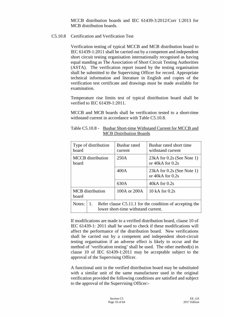
Section C5 Page 16 of 64
EE_GS 2017 Edition
MCCB distribution boards and IEC 61439-3:2012/Corr 1:2013 for MCB distribution boards.
C5.10.8 Certification and Verification Test
Verification testing of typical MCCB and MCB distribution board to IEC 61439-1:2011 shall be carried out by a competent and independent short circuit testing organisation internationally recognised as having equal standing as The Association of Short Circuit Testing Authorities (ASTA). The verification report issued by the testing organisation shall be submitted to the Supervising Officer for record. Appropriate technical information and literature in English and copies of the verification test certificate and drawings must be made available for examination. Temperature rise limits test of typical distribution board shall be verified to IEC 61439-1:2011. MCCB and MCB boards shall be verification tested to a short-time withstand current in accordance with Table C5.10.8. Table C5.10.8 - Busbar Short-time Withstand Current for MCCB and
MCB Distribution Boards Type of distribution board
Busbar rated current
Busbar rated short time withstand current
MCCB distribution board
250A 23kA for 0.2s (See Note 1) or 40kA for 0.2s
400A 23kA for 0.2s (See Note 1) or 40kA for 0.2s
630A 40kA for 0.2s
MCB distribution board
100A or 200A 10 kA for 0.2s
Notes: 1. Refer clause C5.11.1 for the condition of accepting the lower short-time withstand current.
If modifications are made to a verified distribution board, clause 10 of IEC 61439-1: 2011 shall be used to check if these modifications will affect the performance of the distribution board. New verifications shall be carried out by a competent and independent short-circuit testing organisation if an adverse effect is likely to occur and the method of ‘verification testing’ shall be used. The other method(s) in clause 10 of IEC 61439-1:2011 may be acceptable subject to the approval of the Supervising Officer. A functional unit in the verified distribution board may be substituted with a similar unit of the same manufacturer used in the original verification provided the following conditions are satisfied and subject to the approval of the Supervising Officer:-
Section C5 Page 17 of 64
EE_GS 2017 Edition
(i) Power loss and terminal temperature rise of the functional unit when tested in accordance with its product standard, is the same or lower;
(ii) The physical arrangement within the distribution board shall be maintained;
(iii) The rating of the distribution board shall be maintained; and (iv) In addition to the temperature rise limits test, other
requirements as listed in Annex D of IEC 61439-1:2011 including the short-circuit requirements should be taken into consideration.
C5.11 MCCB DISTRIBUTION BOARD
C5.11.1 General
The MCCB distribution board shall be wall-mounted factory built assembly housing MCCBs & busbars. The enclosure of the MCCB distribution board shall be constructed from sheet steel having a thickness of not less than 1.5 mm, and shall be designed for general commercial and light industrial applications. The internal separation shall be designed to Form 2b as defined in IEC 61439-2:2011 and the ingress protection shall not be less than IP41. The design, construction and testing specifications of the distribution board shall be verified to comply with IEC 61439-2:2011. MCCB distribution board shall each be provided with a moulded-case isolating switch having a current rating not less than that of the supply side protective device. Moulded-case isolating switch shall meet the relevant requirements of Clauses C5.1 and C5.2. MCCB shall have the breaking capacity to withstand the prospective fault level at the MCCB board. In general, the MCCB board with the short-time withstand current of 40kA for 1 second shall be installed. The EE Contractor may offer MCCB board with lower short-time withstand current in clause C5.10.8 provided that the short-circuit current at the MCCB board is assessed to be lower than 23kA. Calculation shall be submitted to the Supervising Officer for approval for using the lower short-time withstand current MCCB board.
C5.11.2 Busbar
MCCB distribution board shall be provided with vertical triple-pole and neutral copper busbars of rating not less than that of the supply side protective device subject to a minimum of 250 A. The configuration of the busbars, busbar supports and busbar mounting arrangement shall meet the short-time withstand current in clause C5.10.8. Outgoing MCCB shall be mounted horizontally on both sides of the
Section C5 Page 18 of 64
EE_GS 2017 Edition
vertical busbars. The connection between the MCCB and the phase busbars shall be by means of copper tapes and bolted joints.
C5.12 MCB DISTRIBUTION BOARD
C5.12.1 General
The enclosure of a MCB distribution board shall be constructed from sheet steel having a thickness of not less than 1.2 mm, and shall be designed for general commercial and light industrial applications. The ingress protection for the enclosure with the functional units and blanking plates fitted shall be at least IP41. The design and construction of MCB distribution boards shall comply with and be type tested to IEC 61439-3:2012/Corr 1:2013..
C5.12.2 Construction
The moulded back plate assembly shall be of substantial thickness and attached to the back of the enclosure for mounting of MCB. RCCB, RCBO and double pole or triple pole all insulated switch as specified. MCB distribution board shall be provided with a moulded-case, all-insulated, double-pole or three-pole incoming switch-disconnector (isolating switch) having a current rating of not less than that of the supply side protective device. This incoming switch-disconnector shall meet the relevant requirements of Clauses C5.1 and C5.2 with a Utilisation Category of AC-22 A. However, switch-disconnector of Category AC23 A shall be provided in event of any one of the outgoing circuits being fed for motor circuit. Ferrules shall be provided for wires, including earthing, phase and neutral conductors, throughout the distribution board internally for circuit identification. The metal front plate shall be screwed onto the metal box, making the assembly suitable for surface or flush mounting, and shall be supplied with a hinged cover to conceal all operating handles of the circuit breakers and isolating switch. The front plate shall be affixed with phase colour labels and circuit identification chart, and shall be supplied with moulded single way blanking plates. MCB distribution board shall be provided with phase, neutral and earthing terminals for the incoming cables. There shall be one neutral and one earthing terminal for each outgoing MCB circuit and spare ways.
C5.12.3 Method of Mounting MCB distribution board shall be suitable for flush or surface mounting as specified. Flush mounting shall be so arranged that the assembly is
Section C5 Page 19 of 64
EE_GS 2017 Edition
flush with the surface of the wall and shall not cause any adverse effect to the heat dissipation of internal devices.
C5.13 VOLTAGE DIP RIDE-THROUGH DEVICE
Where specified in the Particular Specification, the EE Contractor shall supply and install appropriate voltage dip ride-through device for the equipment/ installation specified so as to assure operation of the equipment/installation be free of interruption as a result of voltage dip occurrence. The voltage dip ride-through device shall comply with the ride-through duration and voltage dip magnitude as specified in the Particular Specification in accordance with the testing method stipulated in IEC 61000-4-11:2004 and IEC 61000-4-34:2005. C5.13.1 Constant Voltage Transformer (CVT)
(a) Constant voltage transformer (CVT), also known as ferroresonant transformer or regulating transformer, shall contain capacitor at the secondary winding in form of parallel resonant connection circuit.
(b) CVT shall perform in an operating principle that when the
secondary magnetic circuit is operating in the saturation region under a resonant effect, the secondary electric circuit shall be decoupled from the primary circuit and thus insensitive to the voltage variation in the primary circuit.
(c) CVT shall be featured with galvanic isolation to ensure there is
no electrical connection between the primary circuit and connected load at secondary windings.
(d) CVT shall be designed to provide a stabilised output voltage of
±3% under full load condition when the input voltage varies between +10% to -50%.
(e) CVT shall be capable of generating sinusoidal wave voltage at
the output even when its primary winding input voltage is distorted to non-sinusoidal waveform, such as square or quasi-square waveforms.
(f) In case of CVT is operated continuously out of the specified
voltage dip ride-through range, the output voltage shall dip as the input voltage dips.
(g) CVT shall be designed at minimum efficiency of 90% at an
operating range of full load to 70% of rated load. (h) CVT shall be provided with built-in over current protection
against short circuits at the output terminals. (i) CVT shall be UL certified or tested to other equivalent
certification.
Section C5 Page 20 of 64
EE_GS 2017 Edition
C5.13.2 Static Tap Switcher Voltage Regulator (STSVR)
(a) Static tap switcher voltage regulator (STSVR) shall comprise multi-tapped autotransformer, static tap switchers and control circuit.
(b) STSVR shall be constructed of battery free, maintenance free,
robust design, highly reliable and durable. (c) The control circuit of STSVR shall monitor the variation of
input supply voltage and regulate the static tap switcher on the autotransformer for maintaining the required output voltage, The tap changing process initiated by the control circuit shall occur at zero crossing of the supply voltage in order to avoid interference or switching transient.
(d) STSVR shall be designed to provide a stabilised output voltage
of ±10% when the input voltage varies between +10% and -50%.
(e) For control circuit voltage ride-through application, STSVR
shall be provided with a built-in timer circuit to control the ride-through duration. Upon expiry of the timed delay, the connected load of STSVR shall be automatically disconnected in case the voltage dip at input supply persists.
(f) For mains power circuit voltage ride-through application,
STSVR shall be designed to deliver continuous output under voltage dip situation with current limiting protection so as to prevent from overloading.
(g) STSVR shall be provided with built-in over current protection
against short circuits at the output terminals. (h) Indicators shall be provided for incoming power supply healthy
and fault alarm. (i) STSVR shall be UL certified or tested to other equivalent
certification. C5.13.3 Voltage Dip Ride-through Inverter (VDRI)
(a) Voltage dip ride-through inverter (VDRI) shall comprise static bypass switch, energy storage capacitor, inverter and microprocessor based control circuits.
(b) VDRI shall be constructed of battery free, maintenance free,
robust design, highly reliable and durable. (c) The static bypass switch of VDRI shall let utility input voltage
to the connected load under normal operation mode. Upon
Section C5 Page 21 of 64
EE_GS 2017 Edition
detection of under voltage at mains input, the static bypass switch shall shut off the supply line and trigger the operation of inverter spontaneously allowing discharge of energy storage at the capacitor for maintaining continuous supply to the connected load.
(d) VDRI shall synchronize with the input voltage, convert and
regulate it into a stepped 50 Hz output voltage of square wave by Pulse Width Modulation technique or other equivalent technology.
(e) For control circuit voltage ride-through application, VDRI shall
be provided with a built-in timer circuit to control the ride-through duration. Upon expiry of the timed delay, the connected load of VDRI shall be automatically disconnected in case the voltage dip at input supply persists or the input being loss of supply.
(f) VDRI shall be designed to perform in compliance with
Semiconductor Equipment and Materials International, SEMI-F47, IEC 61000-4-11, IEC 61000-4-34 or other equivalent standards. Where specified, VDRI shall be capable of performing satisfactory ride-through of voltage dip at any one of the supply phases for 200 ms duration under the remaining supply voltage at 50% of nominal voltage.
(g) VDRI shall be provided with built-in over current protection
against short circuits at the output terminals. (h) VDRI shall be constructed of “Fail-safe” design so that under
all circumstances the failure of VDRI shall not interrupt the system operation, but with the VDRI unit being inoperative in the ride-through function.
(i) VDRI should be high efficiency with at least 97% under full
load operation. (j) Indicators shall be provided for incoming power supply healthy,
energy discharge for ride-through operation and fault alarm. (k) VDRI shall be UL certified or tested to other equivalent
certification.
C5.14 ELECTROMECHANICAL CONTACTORS
C5.14.1 General
Electromechanical contactor shall comply with and be type tested to IEC 60947-4-1:2009. Each shall be of double air-break type with four pole, triple-pole, double-pole or single pole contacts as specified.
Section C5 Page 22 of 64
EE_GS 2017 Edition
Both the main and auxiliary contacts shall be rated for uninterrupted and intermittent duty. The main contact of a contactor shall be silver or silver-faced. Contactor shall have utilisation category suitable for the particular application as shown in Table I of IEC 60947-4-1:2012.
C5.14.2 Performance Requirements
Contactor shall each be capable of making and breaking currents without failure under the conditions stated in Table VII and VIII of IEC 60947-4-1:2012 for the required Utilisation Categories and the number of operation cycle indicated.
C5.14.3 Co-ordination with Short-circuit Protective Devices
Contactor shall comply with the requirements for performance under short-circuit conditions stipulated in IEC 60947-4-1:2012. Type of co-ordination shall be Type “1” unless otherwise specified.
C5.14.4 Control Circuit
Rated control circuit voltage of a contactor shall be the same as that of the main circuit; otherwise, it shall be 24 V, 30 V or 110 V DC as specified.
C5.15 CHANGEOVER SWITCH
Changeover switch shall be either manually or automatically controlled at mains voltage, double air-break, four-pole type and tested to IEC 60947-6-1:2013. Changeover switch shall be rated in Utilisation Categories AC-33 A and capable of making, breaking and carrying continuously the rated current and making on fault without overheating, damage or deterioration. Changeover switch shall be electrically and mechanically interlocked in operation. For automatic changeover switch the changeover action shall be automatic in response to the failure or resumption of supply mains. The control circuit of changeover switch shall incorporate a true power off delay timer to overcome the momentarily mains alternating current power supply interruption. Illuminated indicator for “Mains On” and “Essential Supply On” shall be provided at the cover of the compartment housing a changeover switch.
Section C5 Page 23 of 64
EE_GS 2017 Edition
C5.16 ACTIVE HARMONIC FILTER
C5.16.1 General Requirements
(a) Active harmonic filter (hereinafter referred to as “AHF”) shall be used to eliminate harmonic currents circulating across the installation so that the Total Harmonic Distortion (THD) may be limited to a given percentage as specified in the Building Energy Code or Particular Specification.
(b) AHF shall be installed in parallel with the distribution system,
i.e. shunt connected, wherever attenuation of harmonic current is needed. Preferably, AHF shall be located close to those loads generating harmonic currents in order to avoid circulation of the harmonic currents along the cables.
(c) AHF shall conform to IEC 61000-4-2: 2008, IEC 61000-4-3:
2010, IEC 61000-4-4:2012, IEC 61000-4-5:2014, IEC 61000-6-2:2016, IEC 61000-6-4:2011 or other similar recognised international standards on Electromagnetic Compatibility (EMC) compliance for industrial or commercial applications and shall be manufactured to ISO 9001:2015. Certificate of compliance shall be issued for each standard rating of AHF after being fully tested at the manufacturing facility.
(d) AHF shall be manufactured by a reputable manufacturer which
has continuously manufactured AHF for at least 5 years and their manufacturing facility shall have a local agent to provide full technical support which includes adequate spares holding and technical expertise in testing, commissioning and trouble-shooting. Training shall be provided by the manufacturer’s representatives for government staff on operation and maintenance aspects including essential trouble-shooting techniques.
(e) Full technical details of the AHF as submitted by the
manufacturer shall be provided for the Supervising Officer’s approval and shall cover the following:
(i) technical guide on its applications; (ii) schematic and wiring drawings down to circuit board
level released by the manufacturer; (iii) shop drawings and as-fitted drawings; (iv) operation manuals with commissioning guide; (v) maintenance manuals with trouble-shooting guide; and (vi) parts list and recommended spare parts with price.
Section C5 Page 24 of 64
EE_GS 2017 Edition
(f) Unless otherwise specified, the rated operational voltage and
services condition shall be as specified in Clause C1.2 and Clause C1.1.3. The following technical requirements shall also apply:
(i) No. of phases : 3-phase without/with neutral,
3/4 wires as specified in the Particular Specification;
(ii) Unit capacity : as specified in the Particular Specification;
(iii) Harmonic orders : 2nd order to 25th order or more compensation;
(iv) Filtering efficiency : 85% or more;
(v) Power factor correction : up to 0.98 lagging or more;
(vi) Steady state response : 40 ms or less;
(vii) Ventilation : Forced air cooled;
(viii) Noise level : 65 dBA or less; and
(ix) Heat losses : 8% of rated capacity or less .
(x) THD settings : Selectable %THDi setpoint and %THDv setpoint
(xi) Resonance avoidance : Output at specific harmonic order turned off if resonance detected; or manually turned off
(xii) Communication : Modbus
C5.16.2 Performance Requirements
(a) The operating principle of AHF shall be based upon the
injection of a harmonic current with appropriate phase shift corresponding to the harmonic current drawn by the load which shall be analysed by the AHF continuously. Consequently, the current supplied by the source shall remain sinusoidal under the effective operating range of the AHF.
(b) AHF shall be compatible with any type of load, and shall
guarantee efficient compensation, even when changes are made to the installation. The AHF shall also be capable of delivering
Section C5 Page 25 of 64
EE_GS 2017 Edition
its rated output harmonic current to the point of connection irrespective of load condition.
(c) If the compensation of neutral harmonic current is required, in
the neutral conductor, the AHF shall be capable of compensating the harmonic current three times greater than the phase current, particularly to compensate harmonic current of order 3 and its multiples.
(d) Start-up and shut down of AHF shall be initiated by control
push buttons or other means as specified in the Particular Specification. After a main power break-down, start-up of AHF shall be automatic.
(e) Should the AHF be overloaded during transient operation of
certain loads or permanently, this should not affect the reliability of its operation. Under such circumstance, the AHF shall operate in a current limiting mode and still deliver to the network its rated harmonic current.
(f) For better adaptation to any installation, AHF shall be capable
of operating in association with other harmonic reduction systems. For ease of expansion, it shall be modular type or be possible to associate 2 or more AHF’s in parallel to increase the compensation capacity and to enhance dependability, i.e. redundant operation.
(g) To compensate the harmonics at different levels in the
distribution network, it shall be possible to connect the AHF at any point in the distribution network, or to connect several AHF’s at different points in the installation for maximum effectiveness.
C5.16.3 Construction
(a) AHF shall use an isolated gate bipolar transistor (IGBT) bridge or other similar technique to inject the proper harmonic current on the network, and will be controlled by a microprocessor based system.
(b) AHF shall be housed in an industrial grade cabinet constructed
from high quality steel sheet of minimum 1.2 mm thick side and back plate and 1.5 mm thick hinged front door with key lock. Protection class of the cabinet shall be not less than IP21 for indoor and IP55 for outdoor application. The entire surface shall be applied with chemical rust inhibitor, rust resisting primer coat and topcoat to give maximum corrosion protection.
(c) The dimension of AHF shall be as small as possible.
Particularly, it will be preferable to have the AHF fitted in low voltage cubicle switchboard or in motor control centre.
Section C5 Page 26 of 64
EE_GS 2017 Edition
(d) AHF shall at least include the following kinds of protection:
(i) thermal overload protection; (ii) internal short circuit protection; and (iii) invertor bridge abnormal operation protection. A three or four poles circuit breaker shall be installed close to the point of the connection to the system to protect the connection cables. It shall be selected according to general selection practice for circuit breakers and the manufacturer recommendation.
(e) As a minimum the AHF shall include the following read-out information at display panel:
(i) an indicator for each phase of the incoming power
supply; (ii) an indicator for normal operating condition; (iii) an indicator for AHF shut down; and (iv) an indicator for fault condition. Also a diagnostics panel shall be accessible from the front of the unit to help the operator to identify the origin of abnormal situation and control push buttons will be provided for ON/OFF operation and alarm reset. The front display unit shall be capable of working independently or powered up by separate tool through a service port featured at each AHF without energising the AHF for diagnostics in case of AHF breakdown. The display shall provide past performance and display of all parameter set points and the event log at the juncture before the breakdown of AHF.
(f) AHF shall be equipped with built-in RS 485/232 serial
communication ports for control, programming and monitoring of the AHF by PC or other user interface.
C5.17 SURGE PROTECTION DEVICE
C5.17.1 General Requirements
(a) Unless otherwise specified, surge protection device shall be suitable for the rated operational voltage as specified in Clause C1.2.
Section C5 Page 27 of 64
EE_GS 2017 Edition
(b) The operation of surge protection device shall base on the use of metal oxide varistor or other similar technique to effectively limit over-voltage under surge conditions and to safely divert the excessive surge energy to ground.
(c) Surge protection device shall be manufactured by a reputable
manufacturer which has been continuously manufacturing surge protection products preferably for at least 5 years and the manufacturer shall have a local agent to provide full technical support and after sales services.
(d) Type test certificate for the surge protection device shall be
submitted for approval by the Supervising Officer. The certificate shall, unless otherwise specified, demonstrate that the equipment can fulfill the requirements stipulated in IEC 61643-11:2011 with the following performance: (i) Surge protection device at the main L.V. switchboard
shall be able to perform under a standard test wave of 20 kV 1.2/50 µs voltage impulse and 10kA 8/20 µs current impulse;
(ii) Surge protection device at the electrical distribution
system shall be able to perform under a standard test wave of 6 kV 1.2/50 µs voltage impulse and 3 kA 8/20 µs current impulse. It shall limit the transient voltage to below equipment susceptibility levels; and
(iii) Surge protection device at sub-main distribution board
shall be able to perform under a standard test wave of 6 kV 1.2/50 µs voltage impulse and 0.5 kA 8/20 µs current impulse.
(e) Surge protection device shall be shunt or series connected to the
concerned electrical installation to achieve maximum protection as recommended by the manufacturer. It shall be installed in strict compliance with manufacturer’s installation instructions and relevant safety standards and regulations.
(f) Except for the panel mounted surge protection device, all
components and circuits of the surge protection device shall be contained in a metal enclosure suitable for wall mounting. The enclosure shall be electrically earthed. In case of floor mounting is required because of its size and weight, the device shall be installed and mounted on concrete plinth provided for this purpose.
(g) Detailed installation instructions and manuals from the surge
protection device manufacturer shall be submitted to the Supervising Officer for approval.
Section C5 Page 28 of 64
EE_GS 2017 Edition
C5.17.2 Performance Requirements
(a) The device shall be able to give protective performance in all modes, including Phase and Neutral, Phase and Earth, and Neutral and Earth.
(b) The device shall be designed in such a way that its performance
shall not be easily affected by field wiring practice. (c) The let-through voltage, i.e. the transient overvoltage which is
allowed through a surge protection device, shall be clearly specified for the acceptance by the Supervising Officer. Unless otherwise specified, the let through voltage shall not exceed the impulse withstand voltage of the equipment to be protected specified in IEC 60364-4-44:2015. The reaction time between the start of the surge and the time the surge protection device initiates the protective action shall be less than 1 nanosecond.
(d) Surge protection device shall be able to withstand repeated
electrical surges appeared in the electrical system without undue degradation of its surge protection performance under healthy condition.
C5.17.3 Construction
(a) Surge protection device shall incorporate both high energy clamping devices and special filtering circuitry to reduce any electrical surge appearing in the connected electrical system to an acceptable level without causing any damage to the connected electrical and electronic equipment.
(b) For panel mounting, the installation method and construction of
the surge protection device shall refer to the manufactruer’s instruction and recommendation. For wall mounting and floor mounting, surge protection device shall be housed in an industrial grade cabinet with hinged and lockable front door made of high quality 1.5mm thick steel sheet. The device and the enclosure shall be electrically earthed. The entire cabinet shall also conform to the requirement of the manufacturer of the surge protection device.
(c) Surge protection device shall be equipped with monitoring
facilities so that whenever its surge protection performance is reduced to a pre-determined level below its original rating after a number of incident surges it has been subjected to, an audible and visual alarm shall be given off to indicate that the device requires servicing or replacement. The audible and visual alarm may be given through a build-in facility inside the device or by activating an electrical dry contact to which an indicator and an alarm bell are connected. As an option, a surge counter shall be required if specified in the Particular Specification.
Section C5 Page 29 of 64
EE_GS 2017 Edition
C5.18 SOLID STATE SOFT MOTOR STARTER
C5.18.1 General Requirements
(a) The solid state soft motor starter (hereinafter referred to as “softstarter”) shall be of the power electronic type motor starting device. It shall control the voltage applied to the motor smoothly by varying the conduction angle of the solid stage AC switches which can be triacs, reverse parallel connected SCR-diode circuit or reverse parallel connected SCR-SCR circuit, etc. or using other similar technique.
(b) Softstarter shall be manufactured to conform to the following
relevant standards or other similar recognised international standards:
(i) IEC 60068-2-6:2007 : for vibration resistance where
softstarter is affected by vibration;
(ii) IEC 60068-2-27:2008 : for shock resistance where softstarter is affected by shock;
(iii) IEC 61000-4-2:2008 : for electrostatic discharge immunity test;
(iv) IEC 61000-4-3:2010 : for radiated, radio-frequency, electromagnetic field immunity test;
(v) IEC 61000-4-4:2012 : for electrical fast transient/burst immunity test; and
(vi) IEC 61000-4-5:2014 : for surge immunity test.
(c) The softstarter shall be manufactured by a reputable manufacturer which has continuously manufactured softstarter for at least 5 years and their manufacturing facility shall have a local agent to provide full technical support, including adequate spares holding and technical expertise in testing, commissioning and trouble-shooting. Training shall be provided by the manufacturer’s representatives for government staff on operational and maintenance aspects including essential trouble-shooting techniques.
(d) Full technical details of the softstarter provided by the
manufacturer shall be submitted and shall cover at least the following:
(i) technical guide on its applications; (ii) schematic and wiring drawings down to circuit board
level;

Section C5 Page 30 of 64
EE_GS 2017 Edition
(iii) shop drawings and as-fitted drawings; (iv) operation manuals with commissioning guide; (v) Maintenance manuals with trouble-shooting guide; and (vi) parts list and recommended spare parts with price.
(e) Degree of Protection of Enclosure
The softstarter shall be protected to at least IP44 for indoor and IP55 for outdoor application by a single front-access enclosure and shall be suitable for operation without derating under ambient temperature of up to 40oC and relative humidity of up to 99%.
(f) Unless other specified, the rated operational voltage shall be as specified in Clause C1.2. The rated power and quantities of the softstarters shall be as specified in the Particular Specification or the Drawings.
C5.18.2 Performance Requirements
(a) Mode of Operation Softstarter shall provide the following modes of operation and shall be transitionless without causing any current inrush and torque surges during operation: (i) Voltage ramp - The motor voltage shall begin initially at
a preset ‘start voltage’ and increase to line voltage at a preset ‘ramp rate’. The acceleration ramp time shall be adjustable up to 30 seconds;
(ii) Current limitation - It shall be capable of limiting the
maximum starting current which shall be adjustable to at least 4 times of rated current;
(iii) Soft stop - A deceleration voltage ramp shall be applied
to the motor for applications which require an extended coast to rest. The voltage ramp down time shall be adjustable to 30 seconds or above;
(iv) Kickstart - A current pulse shall be provided in the
softstarter to develop additional torque when started for loads which may need a boost to get started;
(v) Energy saving – If specified in the Particular
Specification, when the motor is lightly loaded or unloaded for long periods of time, it shall automatically
Section C5 Page 31 of 64
EE_GS 2017 Edition
decrease motor power losses by controlling the motor terminal voltage; and
(vi) Apart from the above, other modes of operation such as
voltage pedestal starting, full voltage starting, DC injection braking, etc. shall also be required when specified in the Particular Specification.
(b) Protection
Softstarter shall have internal protection to the motor and softstarter and LED diagnostics to aid in set-up and troubleshooting. The protection shall includes: (i) thermal overload protection of the motor and softstarter; (ii) mains supply protection for phase failure and phase
unbalance; (iii) internal fault protection; and (iv) stalled motor protection.
(c) Auxiliary Contact
The softstarter shall provide auxiliary contacts for end of starting (by-pass) and fault condition. The output relay contact shall be suitable for 220 V AC operation in category AC11 and DC operation in category DC11.
C5.18.3 Selection of Softstarter and Operating Precautions
(a) The starting current-speed transition curve of the selected softstarter shall closely match with the starting torque-speed characteristics of the motor and loading. The ratings of the softstarter shall base on ‘hot start’ operation i.e. the motor is re-started immediately after operating at maximum rating for a period of time.
(b) The motor associated with the softstarter shall be capable of
starting the driven load when is supplied at reduced voltage and current. In case of severe duty, checking with the motor manufacturer shall be carried out that its derating is compatible with the operating cycle and the starting times.
(c) The heat sink of the softstarter shall be of good quality
aluminium construction and shall provide sufficient thermal inertia to permit successful starting of the motor without exceeding the permitted junction temperature of the solid state AC switches.
Section C5 Page 32 of 64
EE_GS 2017 Edition
(d) The softstarter shall be capable of continuously delivering rated output voltage (or reduced output voltage under energy saving mode) at any load. When using a by-pass contactor, the order to close and open the contactor shall be controlled by the built-in signal of the softstarter.
(e) The softstarter shall have the possibility to accept DC input
from external device such as Programmable Logic Controller (PLC) for controlling the start and stop of the unit.
(f) Semiconductor fuses shall be available as an option and have
the characteristics suitable to protect the softstarter.
(g) The solid stage AC switches shall have a blocking voltage of at least 1,400 V for 415 V system with a rate of rise of reapplied voltage tolerance of at least 1,000 V per microsecond. However, an isolation contactor or isolator shall be available as an option to isolate the supply in the ‘Off’ stage to the softstarter for the safety of the operator.
(h) UNDER NO CIRCUMSTANCES shall the power factor
correction equipment be connected between the softstarter and the motor. If power factor correction equipment is employed, it shall be connected to the supply side of the softstarter.
C5.19 VARIABLE SPEED DRIVES FOR CENTRIFUGAL FANS AND PUMPS
C5.19.1 General Requirements
(a) Variable speed drive (hereinafter referred to as “VSD”) shall be a solid-state converter to convert three phase mains supply of 380 V+6% and 50 Hz+2% to an adjustable voltage and frequency output at its rated throughout power. VSD shall conform to the following standards or other similar recognised international standards on Electromagnetic Compatibility (EMC) compliance for industrial or commercial applications:
(i) IEC 60068-2-6:2007 : for vibration resistance
where VSD is affected by vibration;
(ii) IEC 60068-2-27:2008 : for shock resistance where VSD is affected by shock;
(iii) IEC 61000-4-2:2008 : for electrostatic discharge immunity test;
(iv) IEC 61000-4-3:2010 : for radiated, radio- frequency, electromagnetic field immunity test;
Section C5 Page 33 of 64
EE_GS 2017 Edition
(v)
IEC 61000-4-4:2012 : for electrical fast transient/burst immunity test; and
(vi) IEC 61000-4-5:2014 : for surge immunity test.
VSD shall be manufactured to ISO 9001:2015. Certificate of compliance shall be issued for each standard rating of VSD used in the Contract after being fully tested at the manufacturing facility.
(b) VSD shall be manufactured by a reputable manufacturer which
has continuously manufactured VSD’s for at least 5 years and their manufacturing facility shall have a local agent to provide full technical support which includes adequate spares holding and technical expertise in testing, commissioning and trouble-shooting. Training shall be provided by the manufacturer’s representatives for the Employer’s representatives on operational and maintenance aspects including essential trouble-shooting techniques.
(c) Full technical details of the VSD shall be submitted by the
manufacturer through the EE Contractor and shall cover the following:
(i) technical guide on its applications; (ii) schematic and wiring drawings down to circuit board
level; (iii) shop drawings and as-fitted drawings; (iv) operation manuals with commissioning guide; (v) maintenance manuals with trouble-shooting guide; and (vi) parts list and recommended spare parts with price.
(d) VSD shall be capable of continuously delivering rated output voltage even when the mains supply voltage is down by 6% of its nominal value and shall be able to control 3-phase squirrel cage induction motor of class B insulation over a speed range of 20% to 100% continuously and smoothly without the need to derate the motor kW rating and to provide total power factor of not less than 0.9 lagging, without external chokes or power factor correction capacitors, at full load within the speed range. The inrush current shall be zero and during starting, the current shall start from zero and rises as the load accelerates with no danger of exceeding full load current.
(e) VSD shall allow up to 100 metres of cables to be used between
the VSD and the motor.
Section C5 Page 34 of 64
EE_GS 2017 Edition
(f) VSD shall allow unlimited switching of the motor circuit, at any
load and within the controlled speed range without damage and without the need of auxiliary control switching. The VSD shall be capable of automatically reconnecting to a spinning fan and run without tripping, following mains interruption and on transfer from backup source. The VSD shall be capable of running with no motor connected during functional testing. The VSD shall have voltage/frequency (V/f) ratio suitable for centrifugal pumps and fans control. Selectable V/f ratios shall be provided and it shall not be possible to set a constant V/f ratio, to prevent damage to connected equipment and to optimise energy usage.
C5.19.2 Performance Requirements
(a) VSD shall be fully rated to provide the performance as follows:
(i) minimum efficiency of 95% at 100% load and not less than 90% at any other operating loads;
(ii) output torque shall be limited to 105% of full load
torque; (iii) no facility for reversing the motor rotation shall be
incorporated; (iv) the limiting harmonics produced by the equipment shall
comply with the following requirements:-
IEC 61000-3-2:2014 Limits - Limits for harmonic current emissions (equipment input current ≤ 16 A per phase);
IEC 61000-3-4:1999 Limits - Limitation of emission of harmonic currents in low-voltage power supply systems for equipment with rated current greater than 16A;
IEC 61000-3-12:2011- Limits for harmonic currents produced by equipment connected to public low-voltage systems with input current > 16A and ≤ 75A per phase; and
IEC 61800-3:2012 Adjustable speed electrical power drive systems - EMC requirements and specific test methods.
(v) comply with the Building Energy Code; and (vi) VSD shall have a maximum capacity as specified in the
Particular Specification.
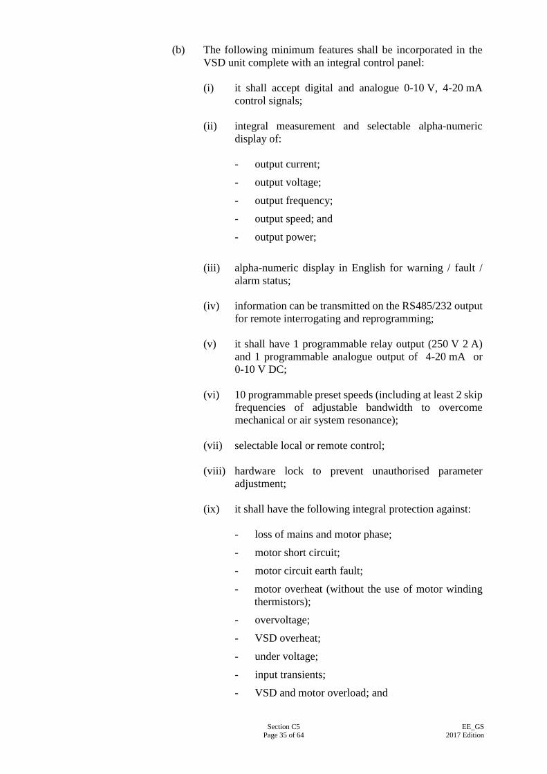
Section C5 Page 35 of 64
EE_GS 2017 Edition
(b) The following minimum features shall be incorporated in the VSD unit complete with an integral control panel:
(i) it shall accept digital and analogue 0-10 V, 4-20 mA
control signals; (ii) integral measurement and selectable alpha-numeric
display of: - output current;
- output voltage;
- output frequency;
- output speed; and
- output power;
(iii) alpha-numeric display in English for warning / fault /
alarm status; (iv) information can be transmitted on the RS485/232 output
for remote interrogating and reprogramming; (v) it shall have 1 programmable relay output (250 V 2 A)
and 1 programmable analogue output of 4-20 mA or 0-10 V DC;
(vi) 10 programmable preset speeds (including at least 2 skip
frequencies of adjustable bandwidth to overcome mechanical or air system resonance);
(vii) selectable local or remote control; (viii) hardware lock to prevent unauthorised parameter
adjustment; (ix) it shall have the following integral protection against:
- loss of mains and motor phase;
- motor short circuit;
- motor circuit earth fault;
- motor overheat (without the use of motor winding thermistors);
- overvoltage;
- VSD overheat;
- under voltage;
- input transients;
- VSD and motor overload; and
Section C5 Page 36 of 64
EE_GS 2017 Edition
- mains input accidentally couples to motor output terminals;
(x) it shall have a digital electronic equivalent of a motor
operated potentiometer control or similar device for open loop operation;
(xi) it shall have an integral full 3-term PID control to
provide close loop control direct from a signal transmitter without need for external signal conditioning; and
(xii) it shall have a facility for controlling motor
anti-condensation heater for heater operation when the motor is idle.
C5.19.3 Construction
(a) VSD shall incorporate a minimum 6-pulse full-wave uncontrolled diode bridge, fixed voltage-fed DC link with inductors and capacitors to form a filter, a mains filter for EMC compliance, a pulse width modulation (PWM) inverter bridge utilising insulated gate bipolar transistors (IGBTs) and output inductors in the motor lines. The inverter bridge shall be controlled by a microprocessor to produce a pulse width modulation (PWM) waveform or similar technique which would result in full motor voltage and sinusoidal current mains supply in the motor circuit. The VSD shall be equipped with built-in RS485/232 serial communication ports.
(b) The complete VSD unit shall be housed in a single front-access
enclosure designed and built as an integral part of the VSD. The enclosure shall be of degree of protection minimum IP20 for indoor application and minimum IP54 for outdoor application. Unless otherwise specified, it shall be suitable for continuous operation without derating under ambient temperature of up to 40oC and relative humidity of up to 95%. The equipment shall be fully tested including motor loading at manufacturer’s facility or by an approved testing authority to certify that the equipment conforms to the aforesaid standard. Certificate of compliance shall be issued for each standard rating of VSD used after being fully tested at the manufacturing facility or by the testing authority.
C5.20 DIGITAL MULTIFUNCTION POWER METER
C5.20.1 General Requirements
(a) The microprocessor based Digital Multifunction Power Meter shall measure the electrical parameters as specified in this Specification by means of microprocessor technology. The
Section C5 Page 37 of 64
EE_GS 2017 Edition
meter shall be able to communicate with PC-based Building Management System via a common network protocol (e.g. Modbus) by means of plugging in communication module and without further modification of the basic unit.
(b) Digital Multifunction Power Meter shall be housed in a single
front access industrial grade enclosure designed and built as an integral part of the meter by the original manufacturer. The meter shall then be panel mounted in the L.V. switchboard cubicles or local motor control panels. Alternatively, the meter can be configured for DIN rail mounting. The display shall either be LED or LCD with backlight, with auto blinking function for prolonging the life of the display.
(c) The meter shall be so arranged that the replacement of meter
shall not require the switching off of the respective switchgear. All wiring shall be routed to allow easy removal of the cable connectors in the event that the meter requires replacement. Current transformers shorting block shall be provided such that current inputs can be disconnected without open circuiting the current transformers. The shorting block shall be wired so as not to affect the operation of protective relays.
(d) The Digital Multifunction Power Meter shall comply with the
requirements specified in IEC 61557-12:2007. (e) The meter shall comply with Electromagnetic Compatibility
(EMC) requirements in accordance with the following international standards:
IEC 61000-4-2:2008 :
Electrostatic discharge immunity test;
IEC 61000-4-3:2010 :
Radiated, radio-frequency, electromagnetic field immunity test;
IEC 61000-4-4:2012 :
Electrical fast transient/burst immunity test;
IEC 61000-4-5:2014 :
Surge immunity test; and
IEC 61000-3-2:2014/ CORR:2009
:
Limits for harmonic current emissions.
Manufacturer’s calibration certificate shall be issued for every Digital Multifunction Power Meter.
C5.20.2 Technical Requirements
(a) Digital Multifunction Power Meter shall comply with the following technical requirements:
Section C5 Page 38 of 64
EE_GS 2017 Edition
(i) Voltage input
- Maximum direct voltage
:
380 V AC between phase;
(ii) Current input (In)
: On current transformers, In / 5 A (secondary);
(iii) Measurement :
- True RMS value of line current for each phase and neutral current
- True RMS value of phase-neutral voltage for each phase
- True RMS value of line voltage for each phase
- Active power, kW
- Reactive power, kVAr
- Apparent power, kVA
- Frequency, Hz
- Power factor
- Active energy, kWh
- Harmonic distortion for voltage and current, up to 15th harmonic orders
- Total harmonic distortion for voltage and current;
(iv) Accuracy
- Voltage
- Current
- Power
- Power factor
- Frequency
- Active energy
- Harmonic distortion
:
:
:
:
:
:
+0.5%
+0.5%
+0.5%
+1%
+0.5%
Class 0.5 S of IEC 62053-22
+1%;
(v) Service condition
- Temperature
- Relative humidity
:
:
0° to 50°C Up to 80%; and
Section C5 Page 39 of 64
EE_GS 2017 Edition
(vi) Communication - Numeric
:
Series link RS-232 or RS-485 Analog communication can be regarded as an optional feature.
(b) Digital Multifunction Power Meter shall store in non volatile
flash memory the maximum and minimum values of the each parameter measured by the unit. The values in memory shall be recalled and displayed upon pressing of a switch on the meter.
C5.21 CHARGER AND BATTERY SET
C5.21.1 General Requirements
(a) Battery charger set shall be a solid state secondary DC power
supply unit operating in parallel with a battery bank. The maximum rated capacity referred to herein this specification shall be 3 kVA. The exact rated capacity shall be designed by the EE Contractor to supply a constant voltage current for the combined standing load and alarm / switch tripping load , if applicable, or not less than 15 Amperes or as specified in the Particular Specification, as well as recharging and restoring the battery bank back to its constant potential voltage setting within the specified time limit after fully discharge.
(b) The charger unit shall consist of a rectifier bridge which has the
AC mains input supplied via the isolation transformer and has the ripples of its DC output smoothed by a DC filter before supplying connected load under normal operation or the battery after discharging in AC mains failure. The rectifier shall be equipped with two voltage levels output, trickle charge and high rate charge (hereinafter called boost charge) which shall be fully automatically controlled and switched by a control logic unit comprising the printed circuit boards (hereinafter called PCB).
(c) Battery charger set shall be manufactured to conform to the
currently-in-forced editions of the relevant standards as indicated below:
BS EN 61204:1995 : Specification for Performance
Characteristics and Safety Requirements of Low-voltage Power Supply Devices, DC Output;
IEC 61204:2001 : Rating and Performance;
BS 7430:2011/A1: 2015
: Code of Practice for Earthing; and
Section C5 Page 40 of 64
EE_GS 2017 Edition
IEC 60950-1:2013 /CORR2:2013
: Specification for Safety of IT Equipments, including Electrical Business Equipment.
(d) the unit shall be able to recharge and restoring the battery bank
back to its constant potential voltage setting in not more than twenty-four (24) hours unless otherwise specified after fully discharged.
(e) The battery bank shall have sufficient voltage and rated
capacity in ampere-hour rating to maintain the connected load at the rated output capacity for the duration specified below. The EE Contractor shall submit calculation to demonstrate that the offered capacity of the battery and charger unit is able to cope with the power demand of the whole system. In any case, the ampere-hour rating shall be not less than 10 ampere-hour if it is not specified in the Particular Specification. The battery shall be sealed, high rate maintenance free nickel-metal hydride type, or a type of better functions and performance and approved by the Supervising Officer and shall have a proven life expectancy of at least 4 years. It shall not have any memory effect to affect its usable life or performance. The nickel-metal hydride battery shall comply with IEC 61951-2: 2011 where applicable.
(f) Battery charger set shall be designed and manufactured by a
reputable manufacturer which has continuously manufactured battery set to work in conjunction with a wide range of applications for at least 5 years and their manufacturing facility shall have a local agent to provide full technical support which includes adequate spare holding and technical expertise in testing, commissioning and trouble-shooting.
(g) The following technical information shall be submitted to the
Supervising Officer for approval prior to ordering of equipment: (i) Technical catalogues and specification, calculation sheet
for charger and battery capacity;
(ii) Power supply unit circuit diagram;
(iii) Circuit diagram of control and battery disconnected;
(iv) Printed circuit board diagram;
(v) Power supply unit front plate layout; and
(vi) Power supply unit console detail. C5.21.2 Technical Requirements
The following technical requirements shall apply:
Section C5 Page 41 of 64
EE_GS 2017 Edition
(a) Input voltage : 220 V AC +10%;
(b) Frequency : 50 Hz +5%;
(c) Output ripple voltage
: +5% of DC output;
(d) Output voltage : 12 V/24 V/30 V/48 V (+1%) or to suit application;
(e) Overcurrent protection
: Mains fuse, charger fuse, battery fuse against overload and short circuit conditions;
(f) Control : Manual boost charge, automatic trickle charge and boost charge;
(g) Indication : - Mains and charger healthy;
- Charger short-circuit;
- Battery connected;
- Battery low-volt; and
- Boost charge;
(h) Voltage-free contact
: Voltage-free contacts for “load on battery” and “battery low voltage” should be provided if specified in Particular Specification for remote monitoring; and
(i) Input connection : 13 A fused AC supply. C5.21.3 Construction
(a) The charger and battery set shall be housed in an industrial
grade cabinet constructed from high quality steel sheet of minimum 1.2 mm thick side and back plate and 1.5 mm thick hinged front door with key lock. Protection class of the cabinet shall be not less than IP31 for indoor and IP55 for outdoor application as specified in BS EN 60529:1992. The entire enclosure surface shall be applied with chemical rust inhibitor, rust resisting primer coat and top coat to give maximum corrosion protection.
(b) The logic PCB, together with the isolation transformer and fused mains input terminals, shall be factory assembled on a plate located at the rear of the case. The power transistors are mounted on heatsinks, separately from the PCB, on the back plate. The instruments and LED indicators are mounted on the front door of the cabinet. A lower ventilated compartment inside the cabinet provides adequate space for accommodation of the storage battery bank and ventilation.
(c) The cabinet shall be suitable for wall-mount or installation inside a switch cubicle where appropriate.
Section C5 Page 42 of 64
EE_GS 2017 Edition
C5.21.4 Selection Criteria
(a) The rated kVA capacity, voltage, current of the rectifier charger
and the storage capacity, terminal voltage, ampere-hour rating of the battery bank shall be designed by the manufacturer and selected by the EE Contractor that it is suitable to work in conjunction with a range of application in switch tripping / fire alarm and protection system / gas detection system / security system / PA and audio system.
(b) For the switch tripping of cubicle switchboards, the selected
charger and battery set shall satisfy the following criteria:
(i) Output voltage : 24 V, 30 V, 48 V or operating voltage of tripping coil as specified in the Particular Specification;
(ii) Output current and re-charge time
: 15 A or 20 times operating current of tripping coil for air circuit breaker and upon mains restoration, adequate to re-charge the battery from fully discharge to fully charge within 24 hours as specified in the Particular Specification; and
(iii) Ampere-hour rating
: 10 Amp-hour or Upon mains failure, adequate to discharge the tripping current of the associated air circuit breaker(s) consecutively at least 20 times up to twenty air circuit breaker(s) simultaneously or as specified in the Particular Specification.
(c) When used in conjunction with in fire alarm and protection
system / gas detection system, the selected charger and battery set shall satisfy the following criteria:
(i) Output voltage : 24 V;
(ii) Output current
and re-charge time
:
15 A or output current for combined standing load at normal condition and alarm load at maximum alarm condition and upon mains restoration, adequate to re-charge the battery from discharge to fully charge within 24 hours or as specified in the Particular Specification; and
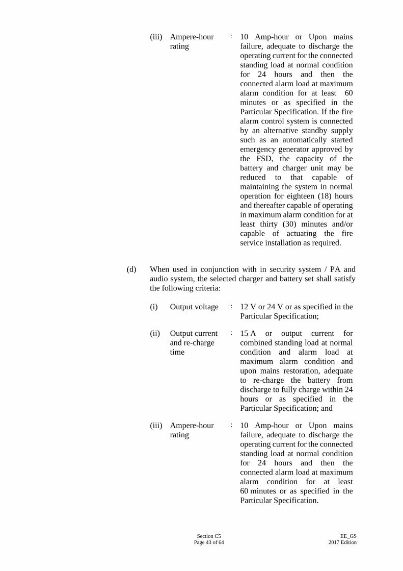
Section C5 Page 43 of 64
EE_GS 2017 Edition
(iii) Ampere-hour rating
: 10 Amp-hour or Upon mains failure, adequate to discharge the operating current for the connected standing load at normal condition for 24 hours and then the connected alarm load at maximum alarm condition for at least 60 minutes or as specified in the Particular Specification. If the fire alarm control system is connected by an alternative standby supply such as an automatically started emergency generator approved by the FSD, the capacity of the battery and charger unit may be reduced to that capable of maintaining the system in normal operation for eighteen (18) hours and thereafter capable of operating in maximum alarm condition for at least thirty (30) minutes and/or capable of actuating the fire service installation as required.
(d) When used in conjunction with in security system / PA and
audio system, the selected charger and battery set shall satisfy the following criteria:
(i) Output voltage
: 12 V or 24 V or as specified in the
Particular Specification;
(ii) Output current and re-charge time
: 15 A or output current for combined standing load at normal condition and alarm load at maximum alarm condition and upon mains restoration, adequate to re-charge the battery from discharge to fully charge within 24 hours or as specified in the Particular Specification; and
(iii) Ampere-hour rating
: 10 Amp-hour or Upon mains failure, adequate to discharge the operating current for the connected standing load at normal condition for 24 hours and then the connected alarm load at maximum alarm condition for at least 60 minutes or as specified in the Particular Specification.
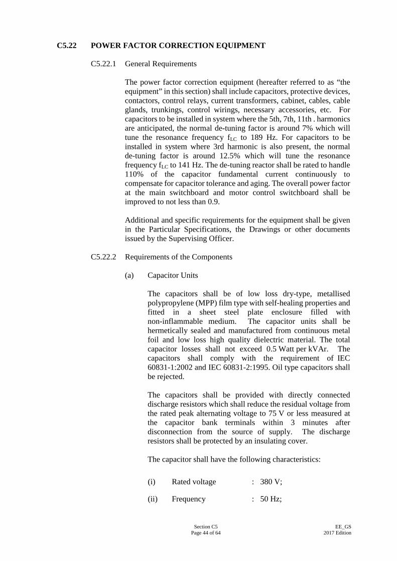
Section C5 Page 44 of 64
EE_GS 2017 Edition
C5.22 POWER FACTOR CORRECTION EQUIPMENT
C5.22.1 General Requirements The power factor correction equipment (hereafter referred to as “the equipment” in this section) shall include capacitors, protective devices, contactors, control relays, current transformers, cabinet, cables, cable glands, trunkings, control wirings, necessary accessories, etc. For capacitors to be installed in system where the 5th, 7th, 11th . harmonics are anticipated, the normal de-tuning factor is around 7% which will tune the resonance frequency fLC to 189 Hz. For capacitors to be installed in system where 3rd harmonic is also present, the normal de-tuning factor is around 12.5% which will tune the resonance frequency fLC to 141 Hz. The de-tuning reactor shall be rated to handle 110% of the capacitor fundamental current continuously to compensate for capacitor tolerance and aging. The overall power factor at the main switchboard and motor control switchboard shall be improved to not less than 0.9. Additional and specific requirements for the equipment shall be given in the Particular Specifications, the Drawings or other documents issued by the Supervising Officer.
C5.22.2 Requirements of the Components
(a) Capacitor Units The capacitors shall be of low loss dry-type, metallised polypropylene (MPP) film type with self-healing properties and fitted in a sheet steel plate enclosure filled with non-inflammable medium. The capacitor units shall be hermetically sealed and manufactured from continuous metal foil and low loss high quality dielectric material. The total capacitor losses shall not exceed 0.5 Watt per kVAr. The capacitors shall comply with the requirement of IEC 60831-1:2002 and IEC 60831-2:1995. Oil type capacitors shall be rejected. The capacitors shall be provided with directly connected discharge resistors which shall reduce the residual voltage from the rated peak alternating voltage to 75 V or less measured at the capacitor bank terminals within 3 minutes after disconnection from the source of supply. The discharge resistors shall be protected by an insulating cover. The capacitor shall have the following characteristics:
(i) Rated voltage : 380 V;
(ii) Frequency : 50 Hz;
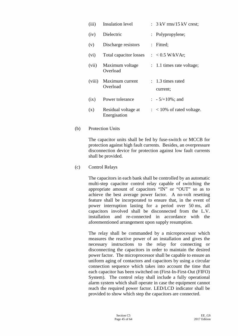
Section C5 Page 45 of 64
EE_GS 2017 Edition
(iii) Insulation level : 3 kV rms/15 kV crest;
(iv) Dielectric : Polypropylene;
(v) Discharge resistors : Fitted;
(vi) Total capacitor losses : < 0.5 W/kVAr;
(vii) Maximum voltage Overload
: 1.1 times rate voltage;
(viii) Maximum current Overload
: 1.3 times rated
current;
(ix) Power tolerance : - 5/+10%; and
(x) Residual voltage at Energisation
: < 10% of rated voltage.
(b) Protection Units
The capacitor units shall be fed by fuse-switch or MCCB for protection against high fault currents. Besides, an overpressure disconnection device for protection against low fault currents shall be provided.
(c) Control Relays
The capacitors in each bank shall be controlled by an automatic multi-step capacitor control relay capable of switching the appropriate amount of capacitors “IN” or “OUT” so as to achieve the best average power factor. A no-volt resetting feature shall be incorporated to ensure that, in the event of power interruption lasting for a period over 50 ms, all capacitors involved shall be disconnected from the L.V. installation and re-connected in accordance with the aforementioned arrangement upon supply resumption. The relay shall be commanded by a microprocessor which measures the reactive power of an installation and gives the necessary instructions to the relay for connecting or disconnecting the capacitors in order to maintain the desired power factor. The microprocessor shall be capable to ensure an uniform aging of contactors and capacitors by using a circular connection sequence which takes into account the time that each capacitor has been switched on (First-In-First-Out (FIFO) System). The control relay shall include a fully operational alarm system which shall operate in case the equipment cannot reach the required power factor. LED/LCD indicator shall be provided to show which step the capacitors are connected.
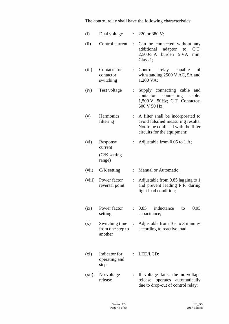
Section C5 Page 46 of 64
EE_GS 2017 Edition
The control relay shall have the following characteristics:
(i) Dual voltage : 220 or 380 V;
(ii) Control current : Can be connected without any additional adaptor to C.T. 2,500/5 A burden 5 VA min. Class 1;
(iii) Contacts for contactor switching
: Control relay capable of withstanding 2500 V AC, 5A and 1,200 VA;
(iv) Test voltage : Supply connecting cable and contactor connecting cable: 1,500 V, 50Hz; C.T. Contactor: 500 V 50 Hz;
(v) Harmonics filtering
: A filter shall be incorporated to avoid falsified measuring results. Not to be confused with the filter circuits for the equipment;
(vi) Response current
(C/K setting range)
: Adjustable from 0.05 to 1 A;
(vii) C/K setting : Manual or Automatic;
(viii) Power factor reversal point
: Adjustable from 0.85 lagging to 1 and prevent leading P.F. during light load condition;
(ix) Power factor setting
: 0.85 inductance to 0.95 capacitance;
(x) Switching time from one step to another
: Adjustable from 10s to 3 minutes according to reactive load;
(xi) Indicator for operating and steps
: LED/LCD;
(xii) No-voltage release
: If voltage fails, the no-voltage release operates automatically due to drop-out of control relay;
Section C5 Page 47 of 64
EE_GS 2017 Edition
(xiii) Alarm relay : Yes;
(xiv) Manual switching
: Two push-buttons for manual operation, suitable to check functioning of relay;
(xv) Connection : Plug-in connector; and
(xvi) Mounting : With angle brackets and threaded bolts.
(d) Contactors
The equipment shall be equipped with special contactors for limiting over-current on itself from high inrush current at capacitor switching. The contactors are characterized for having auxiliary contacts equipped with pre-charge resistors. These auxiliary contacts shall be closed before the power contacts such that the connection peak is strongly limited by the effect of the resistors. Contactors shall be adequately rated to make and break the capacitive current at low power factor. This current limitation increases the life of all the components of the equipment, in particular that of the protective devices and capacitors. The contactors shall comply with the requirement of BS EN 60947-4-1:2001. The contactor shall have the following characteristics:
(i) Prospective peak current at Switch-on
: 100 times rated current;
(ii) Maximum operating rate
: 150 operations/hour;
(iii) Electrical life at rated load
: 100,000 – 200,000
operations; and
(iv) Utilisation category : AC6b.
(e) Cabinet
The equipment shall be of cabinet type of at least IP31 (Indoor) and contained in a separate cubicle with control switchgear and all other necessary accessories and shall comprise multiple identical capacitor units connected and easily dismountable for its replacement. Integrated cubicle with the L.V. Switchboard installation is not acceptable. The equipment shall be installed in separate compartment segregated from the rest of the L.V. Switchboard such that failure of the equipment will not affect
Section C5 Page 48 of 64
EE_GS 2017 Edition
the operation of the L.V. Switchboard. The equipment shall be housed in a front-access industrial grade enclosure with epoxy powder coating. All exposed ferrous metal surfaces of the capacitor bank where applicable shall be treated with rust-inhibiting primer paint, undercoat and finished to a colour approved by the Arhitect.
(f) Blocking Filter or De-tuning Reactor
Each power factor correction capacitor bank/step shall be equipped with series connected blocking filter or de-tuning reactors if specified in the Particular Specification to suppress harmonic and inrush currents for the protection of capacitors and components of the installation, as well as to avoid or attentuate the harmonic amplification present in the power distribution network. The equipment here refers to the power factor correction equipment. The reactors shall be constructed to IEC 60076-6:2007 and shall be rated to handle 110% of the capacitor fundamental current continuously to compensate for capacitor tolerance and aging. The reactor shall be rated to handle 5th harmonic current of a magnitude equal to 15% of the capacitor current rating. The nameplate on the de-tuning capacitor bank shall indicate the rated fundamental and harmonic currents and frequencies. The reactors shall be copper wounded with class H (180°C) insulation system and shall be suitable for an ambient temperature of 40°C and a maximum temperature rise of 100°C. Power loss of the reactor shall be less than 1% of the capacitor kVAr rating. Reactors shall be manufactured in flat or round copper wire technology. They shall be dried and impregnated in a vacuum, which ensures they can withstand high voltages and maintain a long operating life.
C5.23 DIGITAL PROTECTION RELAY
C5.23.1 General Requirements
(a) This digital protection relay is used as standalone type. The
microprocessor-based digital protection relay shall accept three-phase inputs from industrial standard current transformers with nominal secondary current of 1 or 5 Amperes and shall sense the true RMS current values.
(b) The digital protection relay shall provide time delayed
three-phase overcurrent protection and earth fault protection and shall allow a variety of selectable time-current IDMT characteristic curves according to IEC 60255-26:2013 and associated requirements.
(c) The digital protection relay shall have remote operation feature
and shall be able to communicate with PC-based Building
Section C5 Page 49 of 64
EE_GS 2017 Edition
Management System via a common network protocol such as Modbus/Lonworks via RS232/RS485/Ethernet communication link by means of plugging in communication module and without further modification of the basic unit.
(d) The digital protection relay shall be suitable for protection at
main incoming circuit breaker in low voltage electrical system and the tripping characteristics of the relay shall match with the power supply companies' breaker/fuse tripping characteristics for discrimination. The protection scheme and tripping characteristics of the digital relay shall be approved by the power supply companies in Hong Kong.
(e) The digital protection relay shall have continuous
self-supervision feature to monitor the control circuit. Fault recording function shall be triggered upon fault detection or tripping operation for diagnostic use. The monitoring information and relay setting shall be recallable and programmable by means of front panel keypad or remote access by software. The digital relay shall have security password feature to protect access to relay parameter settings and remote tripping.
(f) The digital protection relay shall be type tested for
Electromagnetic Compatibility (EMC) and other relevant requirements in accordance with the following international standards:
IEC 60255-26:2013
: Electrostatic discharge tests;
IEC 60255-26:2013 : Radiated electromagnetic field disturbance test;
IEC 60255-26:2013 : Electrical fast transient/burst immunity test;
IEC 60255-26:2013 : Surge immunity test;
IEC 60255-26:2013 : Electromagnetic emission tests;
IEC 60255-21-1:1988 : Vibration tests; and
IEC 60255-21-2:1988 : Shock and bump test.
Manufacturer’s calibration certificate shall be issued for every digital relay.
Section C5 Page 50 of 64
EE_GS 2017 Edition
C5.23.2 Technical Requirements
(a) The digital protection relay shall comply with the following
technical requirements:
Current input
:
1 A or 5 A via standard protection current transformer;
Overcurrent setting
:
50% to 200% in step of 5% of nominal current In;
Earth fault setting
:
10% to 40% in step of 5% of In;
Time multiple setting
:
0.1 to 1.0 in step of 0.05;
AC burden (maximum)
:
0.25 VA at In = 1 A
0.50 VA at In = 5 A; and
Service condition
:
Temperature range: 0° to 40°C Relative humidity: Up to 95%.
(b) The monitoring and fault records of the digital relay shall be stored in nonvolatile memory and retained in the event of control power interruption. Either using lithium battery or non volatile flash memory for data storage shall be adopted on condition that the memory shall be backup not less than 3 years. Each fault/event record shall include at least the type of faults/alarms, current values, date & time of tripping, etc. The memory shall be capable of storing minimum 5 fault records.
(c) The digital relay shall be accommodated in a dust-proof case to
IP51 and shall be draw-out type flush mounted on the front panel of switchboard cubicle. Facility shall be provided for automatic short-circuiting the associated current transformers upon withdrawal of the module.
(d) The digital relay shall be able to receive auxiliary DC power
supply at 30 V or 48 V for control operation. A battery set and charger shall be provided for digital relay operation.
(e) The digital relay shall provide at least 4 auxiliary contacts for
the input/output of other functions such as remote tripping, alarms, blocking logic, watchdog, etc.
(f) Trip indicators shall be provided for identification of the type of
fault condition.
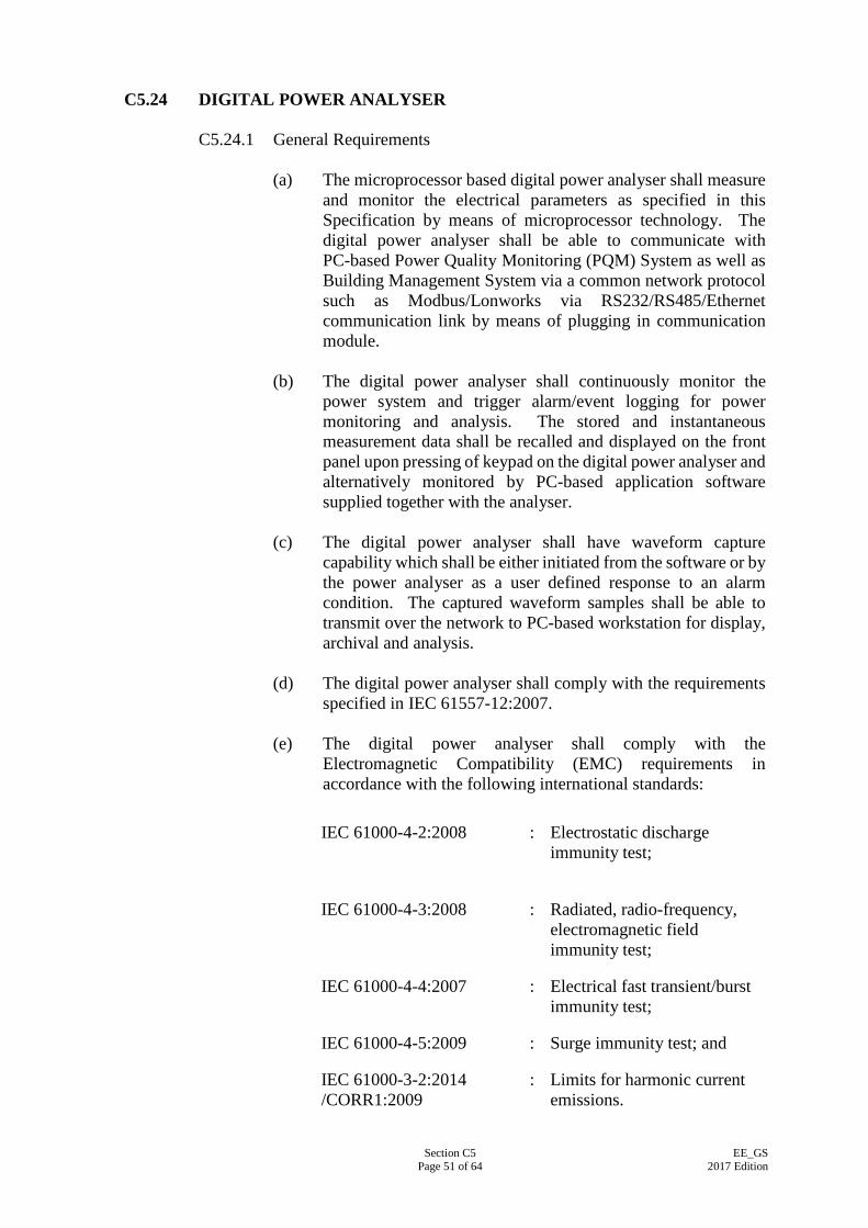
Section C5 Page 51 of 64
EE_GS 2017 Edition
C5.24 DIGITAL POWER ANALYSER
C5.24.1 General Requirements
(a) The microprocessor based digital power analyser shall measure and monitor the electrical parameters as specified in this Specification by means of microprocessor technology. The digital power analyser shall be able to communicate with PC-based Power Quality Monitoring (PQM) System as well as Building Management System via a common network protocol such as Modbus/Lonworks via RS232/RS485/Ethernet communication link by means of plugging in communication module.
(b) The digital power analyser shall continuously monitor the
power system and trigger alarm/event logging for power monitoring and analysis. The stored and instantaneous measurement data shall be recalled and displayed on the front panel upon pressing of keypad on the digital power analyser and alternatively monitored by PC-based application software supplied together with the analyser.
(c) The digital power analyser shall have waveform capture
capability which shall be either initiated from the software or by the power analyser as a user defined response to an alarm condition. The captured waveform samples shall be able to transmit over the network to PC-based workstation for display, archival and analysis.
(d) The digital power analyser shall comply with the requirements
specified in IEC 61557-12:2007. (e) The digital power analyser shall comply with the
Electromagnetic Compatibility (EMC) requirements in accordance with the following international standards:
IEC 61000-4-2:2008 : Electrostatic discharge
immunity test;
IEC 61000-4-3:2008 : Radiated, radio-frequency, electromagnetic field immunity test;
IEC 61000-4-4:2007 : Electrical fast transient/burst immunity test;
IEC 61000-4-5:2009 : Surge immunity test; and
IEC 61000-3-2:2014 /CORR1:2009
: Limits for harmonic current emissions.
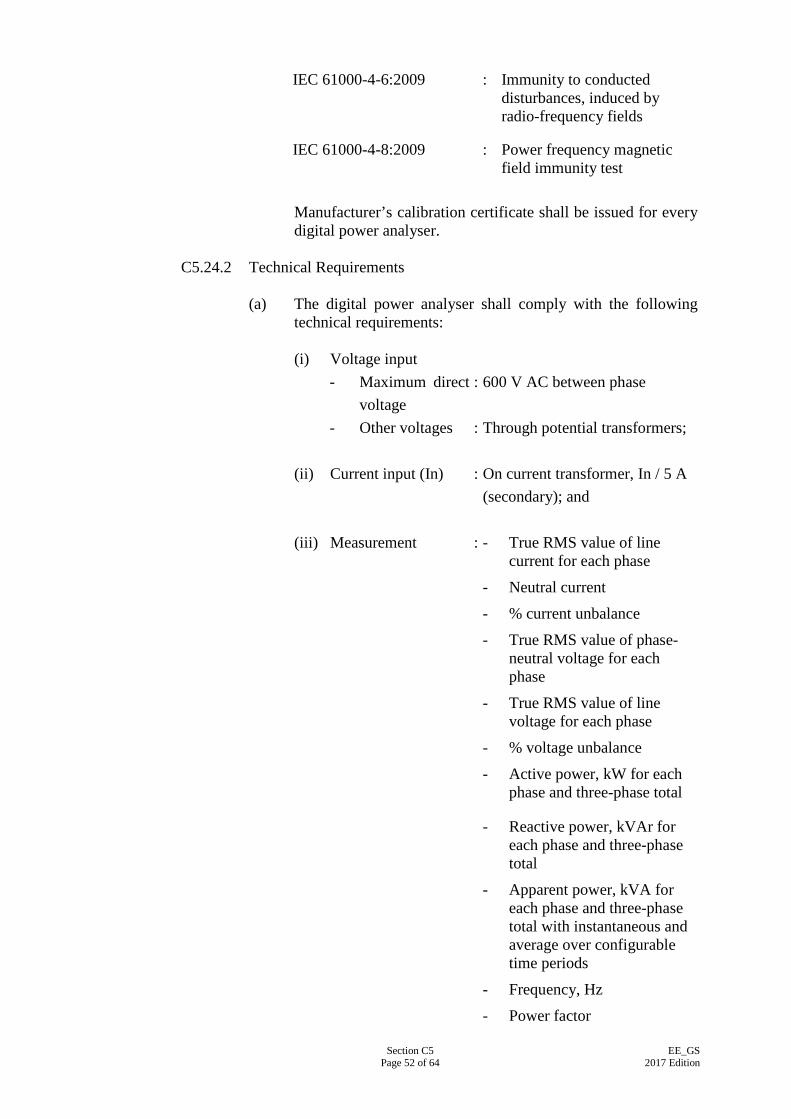
Section C5 Page 52 of 64
EE_GS 2017 Edition
IEC 61000-4-6:2009 : Immunity to conducted disturbances, induced by radio-frequency fields
IEC 61000-4-8:2009 : Power frequency magnetic field immunity test
Manufacturer’s calibration certificate shall be issued for every digital power analyser.
C5.24.2 Technical Requirements
(a) The digital power analyser shall comply with the following technical requirements:
(i) Voltage input
- Maximum direct voltage
: 600 V AC between phase
- Other voltages : Through potential transformers;
(ii) Current input (In) : On current transformer, In / 5 A (secondary); and
(iii) Measurement : - True RMS value of line
current for each phase
- Neutral current
- % current unbalance
- True RMS value of phase- neutral voltage for each phase
- True RMS value of line voltage for each phase
- % voltage unbalance
- Active power, kW for each phase and three-phase total
- Reactive power, kVAr for each phase and three-phase total
- Apparent power, kVA for each phase and three-phase total with instantaneous and average over configurable time periods
- Frequency, Hz
- Power factor

Section C5 Page 53 of 64
EE_GS 2017 Edition
- Active energy, kWh for three-phase total with instantaneous and accumulated values
- Demand current for each phase and three-phase average
- Demand active power, three-phase total
- Demand apparent power, three-phase total
- Harmonic distortion for voltage and current, up to 30th harmonic orders
- Total harmonic distortion for voltage and current;
(iv) Accuracy:
- Voltage : ± 0.5%
- Current : ± 0.5%
- Power : ± 0.5%
- Power factor : ± 0.5%
- Frequency : ± 0.5%
- Active energy : Class 0.2 S of IEC 62053-22
- Harmonic distortion
: ± 1.0%;
(v) Services Condition:
- Temperature : 0° to 40°C
- Relative humidity : Up to 95%; and
(vi) Communication
- Digital : Serial link RS-232 or RS485. Modbus
(b) The digital power analyser shall provide date and time stamped
event log. The type of alarm events and size of the event log shall be user definable. The following classes of events shall be available as alarm events: (i) Over /under voltage;
Section C5 Page 54 of 64
EE_GS 2017 Edition
(ii) Over /under current;
(iii) Current or voltage unbalance;
(iv) Phase loss, voltage or current;
(v) Over /under frequency;
(vi) Overall/total kVA, kW or kVAr into /out of load;
(vii) Under power factor, true or displacement;
(viii) Over THD;
(ix) Over demand, current or power;
(x) Phase reversal; and
(xi) Voltage or current sag /swell.
(c) All setup parameters required by the digital power analyser shall be stored in non volatile flash memory and retained in the event of control power interruption. The memory shall maintain the maximum and minimum values of each parameter measured by the unit.
C5.25 ELECTRIC MOTORS
C5.25.1 General All electric motors shall be of the high efficiency squirrel-cage induction totally enclosed fan-cooled type and comply with IEC 60034-1:2006 and other associated Parts of the Standard. The motors shall be insulated to IEC 60085:2004 with Class F as the minimum insulation, unless otherwise specified. Motor enclosures shall be in accordance with IEC 60034-5:2006 and the 'degree of protection' shall be appropriate to the location in which the motors are operating and the environment indicated. Unless otherwise specified, motors shall be protected with enclosures to at least IP44 for indoor and IP55 for outdoor application. Motors of 2.2 kW output or above shall be suitable for operation from three-phase supply. The synchronous speed of the motor shall not exceed 25 rev/s unless otherwise approved.
C5.25.2 Insulation Test All low voltage motors shall have a minimum insulation resistance of 1 megaohm between phases and to earth when tested with an approved 500 V DC insulation tester.
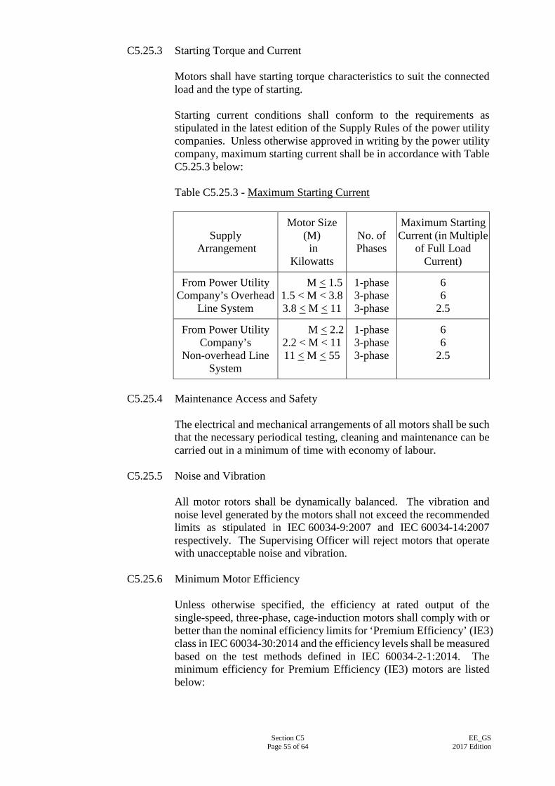
Section C5 Page 55 of 64
EE_GS 2017 Edition
C5.25.3 Starting Torque and Current
Motors shall have starting torque characteristics to suit the connected load and the type of starting. Starting current conditions shall conform to the requirements as stipulated in the latest edition of the Supply Rules of the power utility companies. Unless otherwise approved in writing by the power utility company, maximum starting current shall be in accordance with Table C5.25.3 below: Table C5.25.3 - Maximum Starting Current
Supply
Arrangement
Motor Size (M) in
Kilowatts
No. of Phases
Maximum Starting Current (in Multiple
of Full Load Current)
From Power Utility Company’s Overhead
Line System
M < 1.5 1.5 < M < 3.8 3.8 < M < 11
1-phase 3-phase 3-phase
6 6
2.5
From Power Utility Company’s
Non-overhead Line System
M < 2.2 2.2 < M < 11 11 < M < 55
1-phase 3-phase 3-phase
6 6
2.5
C5.25.4 Maintenance Access and Safety
The electrical and mechanical arrangements of all motors shall be such that the necessary periodical testing, cleaning and maintenance can be carried out in a minimum of time with economy of labour.
C5.25.5 Noise and Vibration All motor rotors shall be dynamically balanced. The vibration and noise level generated by the motors shall not exceed the recommended limits as stipulated in IEC 60034-9:2007 and IEC 60034-14:2007 respectively. The Supervising Officer will reject motors that operate with unacceptable noise and vibration.
C5.25.6 Minimum Motor Efficiency
Unless otherwise specified, the efficiency at rated output of the single-speed, three-phase, cage-induction motors shall comply with or better than the nominal efficiency limits for ‘Premium Efficiency’ (IE3) class in IEC 60034-30:2014 and the efficiency levels shall be measured based on the test methods defined in IEC 60034-2-1:2014. The minimum efficiency for Premium Efficiency (IE3) motors are listed below:
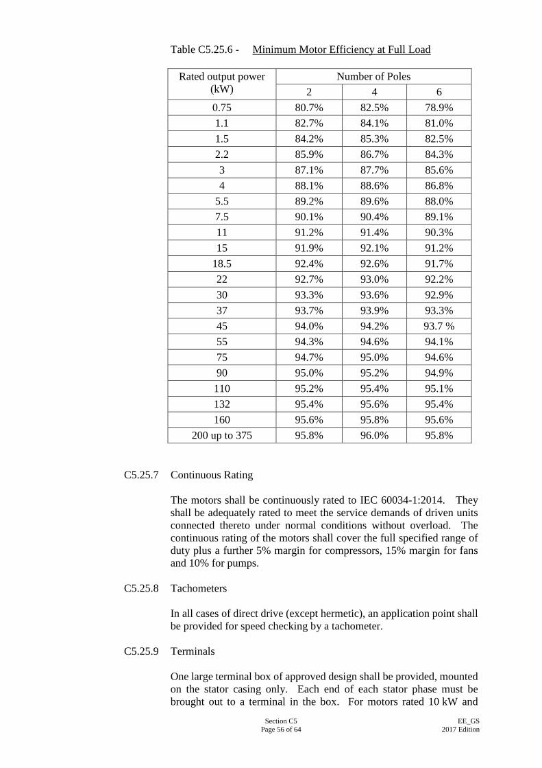
Section C5 Page 56 of 64
EE_GS 2017 Edition
Table C5.25.6 - Minimum Motor Efficiency at Full Load
C5.25.7 Continuous Rating The motors shall be continuously rated to IEC 60034-1:2014. They shall be adequately rated to meet the service demands of driven units connected thereto under normal conditions without overload. The continuous rating of the motors shall cover the full specified range of duty plus a further 5% margin for compressors, 15% margin for fans and 10% for pumps.
C5.25.8 Tachometers In all cases of direct drive (except hermetic), an application point shall be provided for speed checking by a tachometer.
C5.25.9 Terminals
One large terminal box of approved design shall be provided, mounted on the stator casing only. Each end of each stator phase must be brought out to a terminal in the box. For motors rated 10 kW and
Rated output power (kW)
Number of Poles 2 4 6
0.75 80.7% 82.5% 78.9% 1.1 82.7% 84.1% 81.0% 1.5 84.2% 85.3% 82.5% 2.2 85.9% 86.7% 84.3% 3 87.1% 87.7% 85.6% 4 88.1% 88.6% 86.8%
5.5 89.2% 89.6% 88.0% 7.5 90.1% 90.4% 89.1% 11 91.2% 91.4% 90.3% 15 91.9% 92.1% 91.2%
18.5 92.4% 92.6% 91.7% 22 92.7% 93.0% 92.2% 30 93.3% 93.6% 92.9% 37 93.7% 93.9% 93.3% 45 94.0% 94.2% 93.7 % 55 94.3% 94.6% 94.1% 75 94.7% 95.0% 94.6% 90 95.0% 95.2% 94.9% 110 95.2% 95.4% 95.1% 132 95.4% 95.6% 95.4% 160 95.6% 95.8% 95.6%
200 up to 375 95.8% 96.0% 95.8%
Section C5 Page 57 of 64
EE_GS 2017 Edition
above, adequate clearance between termination shall be allowed for the use of cable lugs.
C5.25.10 Anti-condensation Heater Anti-condensation heater shall be provided in damp environment such as sea water pump motors located inside water-front pump chambers, or motors above 30kW.
C5.25.11 Belt Drives and Pulleys
Belt drives shall comply with BS 3790:2006 and be capable of transmitting at least the rated power output of the driving motor with one belt removed. A minimum of two belts per drive shall be used and all multi-belt drives shall use matched sets. Slide rails shall be provided for all motors driving through belts. Purpose-made adjusting devices shall be provided to enable belt tension to be altered and motors to be secured. Belt driven machinery such as fans shall be fitted with pulleys suitable for the belt drive used. Pulleys may use split taper bushings for drives up to 30kW. Alternatively, and in any case for output above 30kW, pulleys shall be secured to the fan and motor shafts by keys fitted into machined keyways. Keys shall be easily accessible so that they can be withdrawn or tightened. Where gib head keys are used they shall not protrude beyond the end of the shaft. For keys without gib heads, they shall be drilled and tapped to accept an extractor bolt.
C5.25.12 Protective Guards Protective fixed guards shall be provided at all forms of open power transmission systems including belt drives and drive couplings, and to dangerous parts of machinery to prevent inadvertent access or contact. The guards shall comply with the safety requirements stipulated by the Labour Department. For belt drives, the guards shall be of galvanised steel wire of not less than 2.5mm diameter attached to a rigid galvanised steel rod or angle framework. The mesh size and the location of the guard shall prevent finger contact with any enclosed danger point. Alternatively guards may be constructed from galvanised sheet steel of not less than 0.8mm thick stiffened to ensure a rigid enclosure. Removable access panels shall be provided in guards to allow tachometer readings to be taken on both driving and driven shafts and also belt tension to be tested. The sizes of guards including the dimensions and locations of access panels shall also allow the size and position of the motor.
C5.25.13 Motor Fed by Converter
As converter drive can generate repetitive voltage overshoots at the terminals of a motor connected by cables, which can reduce the life of
Section C5 Page 58 of 64
EE_GS 2017 Edition
a motor winding insulation system if these repetitive voltage overshoots exceed the repetitive voltage stress withstand capability of the motor winding insulation system, the motor winding insulation shall have the pulse withstand capability at least equal that depicted by Curve A (for motors upto 500 V AC) of Figure 17 of IEC TS 60034-25:2014. In order to avoid damage by bearing currents in converter fed operation, motor of frame size 225 or larger shall be fitted with isolated bearing at the non-drive end.
C5.26 MOTOR SWITCHGEAR, STARTERS AND CONTROL PANEL
C5.26.1 General
Motor switchgear, starters and controls shall be supplied and installed to perform the operation and control of the equipment to be provided. The control panels or switchboards shall incorporate all control devices, timers, accessories and wiring necessary for proper operation.
C5.26.2 Local Motor Control Panels
The local motor control panel shall be of wall-mounted factory built assemblies of low voltage switchboard or distribution board housing the motor starter and switchgear. The panel shall be designed and fabricated to conform with IEC 61439-2:2011 with ingress protection not less than IP41. For the panel housing busbars, the internal separation shall be constructed to Form 2b. The certification and verification test of typical local motor control panel shall comply with the requirements in clause C5.10.8 of this Specification. Apart from the Specification hereunder, the panel shall comply where applicable with the requirements laid down in clause C5.10, C5.11 and C5.12 of this Specification. The panel shall be of steel construction, self supporting, with modular top, side and back panels and doors of sheet steel built up on substantial framing with all necessary stiffeners, supports and return edges to provide a rigid construction and clear accessibility to all internal components within the panel. The thickness of the sheet steel shall be at least 1.6 mm. All panels shall, but not be limited to, include the following operational features: - Local Auto/On/Off switch for each equipment;
- Starter or variable speed drive as shown on the Drawings or as specified in the Particular Specification;
- Fuse switch or circuit breaker for each equipment;
Section C5 Page 59 of 64
EE_GS 2017 Edition
- Isolating switch for each main incoming supply and for each motor starter;
- Protective, control and auxiliary relays;
- Current transformer;
- Digital multifunction power meter for each outgoing circuit and incoming power supply of 60A 3-phase or above;
- Hour run meter;
- LED Indicating lamps, push buttons, selectors and control switches;
- Emergency stop push buttons; and
- Labelling.
Unless otherwise specified, the components above shall comply with the requirements stipulated in the respective sections of this Specification.
C5.26.3 Motor Control Switchboard
The motor control switchboard (hereafter called the “MC Switchboard”) shall be a free-standing floor-mounted low voltage switchboard to group centrally the motor starters, controls and switchgear for the air-conditioning and ventilation equipment etc. The MC Switchboard shall be designed and fabricated to comply with IEC 61439-2:2011. The certification and verification test of typical MC Switchboard shall comply with the requirements in clause C11.15 of this Specification. Apart from the Specification hereunder, the MC Switchboard shall comply where applicable with the requirements laid down in Section C11 of this Specification. If modifications are made to a verified MC Switchboard, clause 10 of IEC 61439-1: 2011 shall be used to check if these modifications will affect the performance of the MC Switchboard. If the EE Contractor can verify the heat dissipation from the starters in the proposed MC Switchboard is not more than those starters installed in the same compartment of the verified MC Switchboard, the temperature rise limit of the proposed MC Switchboard is deemed to be in compliance with IEC 61439-1:2011 according to the method – ‘verification comparison with a tested reference design’. However, new verifications shall be carried out by a competent and independent short circuit testing organisation if an adverse effect is likely to occur and the method of ‘verification testing’ shall be used. The other method(s) in clause 10 of IEC 61439-1:2011 may be acceptable subject to the approval of the Supervising Officer. The MC Switchboard shall, but not be limited to, include the following provisions: - Local Auto/On/Off switch for each equipment;
Section C5 Page 60 of 64
EE_GS 2017 Edition
- Air circuit breaker, fuse switch and/or moulded case circuit breaker;
- Busbars;
- Isolating switch for each main incoming supply and for each motor starter;
- Starter or variable speed drive as shown on the Drawings or as specified in the Particular Specification;
- Protective, control and auxiliary relays;
- Current transformer;
- Digital multifunction power meter for each outgoing circuit and incoming power supply of 60A 3-phase or above;
- Hour run meter;
- LED Indicating lamps, push buttons, selector and control switches;
- Emergency stop push buttons; and
- Labelling.
Unless otherwise specified, the MC Switchboard and associated components above shall comply with the requirements stipulated in the respective sections of this Specification.
C5.26.4 Motor Starters
(a) General Requirements
(i) Motor starters shall generally comply with the requirements of the IEC 60947-4-1:2009 or IEC 62271-106:2011/CORR1:2014.
IEC 60947-4-1:2009 Low-voltage switchgear and controlgear – Part 4-1: Contactors and motor-starters – Electromechanical contactors and motor-starters
IEC 62271-106:2011/CORR1:2014 High-voltage switchgear and controlgear – Part 106: Alternating current contactors, contactor-based controllers and motor-starters
(ii) The duty of the starters shall be suitable for the
mechanical and electrical duties imposed by the motors being switched and in particular, the starting torque, current, starting time and frequency of operation.
(iii) Motor of more than 0.5 kW rating shall be provided with
a starter designed to perform the following functions efficiently and safely:
- To start the motor without damage to the drive or
Section C5 Page 61 of 64
EE_GS 2017 Edition
driven equipment whilst regulating the starting current to the satisfaction of the power supply company and ensuring that at all stages of starting, the motor will develop sufficient torque to accelerate the load;
- To stop the motor; - To prevent damage to the motor due to overload,
under voltage, disconnection of one phase; - To prevent damage to reduced voltage started
motors and danger to personnel due to resumption of the electricity supply following a failure;
- To limit the damage to the motor due to stalling
or internal electrical or mechanical faults by quickly disconnecting the supply; and
- To prevent damage to the motor or the starter
itself due to improper unskilled or hesitant operation or failure to complete a starting sequence once it is connected.
(iv) Motor starters shall comply with the Supply Rules of the
power utility companies. (v) Each motor starter assembly shall comprise fused
switchgear, contactors, protection relays, main and auxiliary contacts, and associated accessories. For starter to be installed in motor control switchboard, the whole unit shall be enclosed in the switchboard from which no access can be gained to adjoining sections of the switchboard. Both the main and auxiliary contacts shall be rated for uninterrupted and intermittent duty.
(vi) All starters shall be of the electrically held-on pattern
and shall not release until the voltage falls below 75% of nominal value.
(vii) All starters shall be of the air-break triple-pole
electro-magnetic type and shall comply with IEC 60947-4-1:2009 or IEC 62271-106:2011/CORR1:2014, with utilisation category suitable for the particular application as shown in Table I of IEC 60947-4-1:2009. The starter shall be capable of making and breaking currents without failure under the conditions stated in Table VII and Table VIII of IEC 60947-4-1:2009 for the required utilisation categories and the number of operation cycle indicated. The duty rating of the contactors shall not be less than intermittent duty class
Section C5 Page 62 of 64
EE_GS 2017 Edition
12 60% on-load factor. Where specified in the Contract, the solid state soft motor starter can be used to start motors over 2 kW.
(viii) The starter shall comply with the requirements for
performance under short-circuit conditions stipulated in IEC 60947-4-1:2009, and type of coordination shall be Type “1” unless otherwise specified.
(ix) Overload relay for a starter shall be of thermal type
unless otherwise specified. The trip class of starters shall be according to the classification of Table II of IEC 60947-4-1:2009. Overload relay shall be able to operate at an ambient air temperature of 40oC and have a setting range of 50% to 150% rated operational current.
(x) For an assisted start starter, timer shall be of solid state
plug-in type with 0 to 15 seconds setting. For star/delta and reversing starter, mechanical and electrical interlocks shall be fitted with the contactor.
(xi) Control circuits shall be operated on main supply
derived from the control panel or switchboard, and protected by fuse to IEC 60269-1:2006.
(xii) Where duplicate equipment is provided, the starter for
each equipment shall be housed in a separate panel. Unless otherwise indicated, where an equipment is provided with duplicate motors, two starters shall be supplied; a single starter with a local changeover switch will not be accepted.
(b) Direct-on-line (DOL) Starters
(i) Unless otherwise specified in the General Specification or Particular Specification for the specific type of installations, motors rated below 11 kW shall be direct-on-line provided that the maximum starting current does not exceed six times the rated motor full load current, otherwise star-delta starters shall be provided.
(ii) The starters shall, but not be limited to, include the
following:
- Fused switchgear; - Triple pole air break contactor; - A triple pole motor protection unit incorporating
over-current and single-phasing protection with manual reset facilities;
Section C5 Page 63 of 64
EE_GS 2017 Edition
- Under-volt release protection device. Unless
otherwise specified, it shall be arranged to provide automatic restart on restoration of mains voltage;
- Current transformers with suitable ratio, output
and accuracy for motor protection; - Local/off/remote control selector switch lockable
in each position; - Start and stop push buttons; - Indicating lamps for motor running, off and
tripped on fault; - Dry contacts wired to terminals for remote
indication of motor running, off, tripped on fault and summary alarm to supervisory control panels;
- Terminals wired to provide for connection to
emergency stop push button and remote start/stop of the motor;
- Hour run meter; and - Lamp test button.
(c) Star-delta Starters
(i) Unless otherwise specified in the General Specification or Particular Specification for the specific type of installations, motors rated at and above 11 kW and up to 55 kW shall be star-delta started to limit the maximum starting current to within 2.5 times the rated motor full load current.
(ii) Star-delta starters shall be equipped as per DOL starters
specified above, with the following additional provisions:
- Triple pole air break contactors with electrical
and mechanical interlock arranged for automatic star-delta transition;
- Calibrated and adjustable solid state timer for
automatic star-delta transition; and - A triple pole motor protection unit incorporating
over-current, single-phasing and earth leakage
Section C5 Page 64 of 64
EE_GS 2017 Edition
protection with manual reset facilities. The earth leakage protection unit shall be selected to isolate the motor circuit with a maximum fault disconnection time of 5 seconds in case of earth leakage without causing nuisance tripping of the motor circuit due to motor starting and transient current transformer saturation.
(d) Auto-transformer Starters
(i) Unless otherwise specified in the General Specification or Particular Specification for the specific type of installations, motors rated above 55 kW shall be reduced voltage started by means of auto-transformer to limit the maximum starting current to within 2.5 times the rated motor full load current.
(ii) Reduced voltage starters shall be equipped as per
star-delta starters specified above, with the following additional provisions:
- Triple pole air break contactor with electrical and
mechanical interlock arranged for automatic reduced voltage transition;
- Air-cooled copper winding auto-transformer
with Class F insulation enclosed in an earthed metal casing suitably ventilated by splash proof louvres. Suitable tappings shall be arranged for closed transition reduced voltage motor starting; and
- Calibrated and adjustable solid state timers for
switching over from reduced voltage to full voltage connection.
Section C6 Page 1 of 6
EE_GS 2017 Edition
SECTION C6
BUSBAR TRUNKING SYSTEM
C6.1 GENERAL Busbar trunking system shall be designed to operate on 220/380 V 3 phase 4 busbar at 50 Hz system and shall be manufactured and tested to verify to comply with IEC 61439-6:2012. Busbar trunking systems manufactured to other standards (such as National Electrical Manufacturers Association (NEMA) of USA and UL listed) with insulation voltage of 415 V may be considered as acceptable provided that the standard of manufacture is not inferior to the relevant IEC standard and that the busbar trunking system meets all the requirements of this Section. All material, components and accessories (such as bends, joints, tees, feeder units, tap-off units, etc.) used for the busbar trunking shall be of the same origin of manufacture. In case where busbar trunkings are manufactured under license from the Principal Company, a letter shall be produced by the Principal Company to guarantee that the products manufactured by the licensee will be equivalent to every respect to the verified standard products. Where busbar trunkings are installed within switchroom for interconnections among LV cubicle switchboards and incoming mains connection of power supply company, the construction of busbar trunking shall comply with IEC 61439-2:2011 as a part of LV cubicle switchboard assembly. Each run of such busbar trunking shall be restricted to not more than 20m length and shall not be installed outside switchroom.
C6.2 BUSBAR TRUNKING CONSTRUCTION The busbar trunking system shall be of the totally enclosed type with ingress of protection not less than IP54 of IEC 60529:2013/Corr 2:2015 for indoor erection in non-sprinklered areas, IP55 of IEC 60529:2013/Corr 2:2015 for indoor erection in sprinklered areas and mechanical plant rooms and IP66 of IEC 60529:2013/Corr 2:2015 for outdoor erection. It shall be constructed to withstand heavy mechanical loads as stated in IEC 61439-6:2012. The casing shall be finished in enamel paint to a grey colour or the nearest manufacturer’s colour of standard production. Adjacent lengths of the busbar casing shall be butt-jointed and the joint shall be mechanically and electrically continuous. The mechanical strength of the joint shall not be less than that of the busbar casing. Colour circles indicating the phase arrangement of the busbars shall be painted on the casing of the terminal units and at any physical compartment. Removal of the cover for access facility shall necessitate the use of tools. For long busbar run, phase transposition of busbar shall be incorporated in accordance with manufacturer’s recommendation.

Section C6 Page 2 of 6
EE_GS 2017 Edition
C6.3 BUSBAR INSULATION
The insulation material shall be of halogen free, heat resistant, self-extinguishing, non-hygroscopic, high electrical and mechanical strength to withstand the stresses under all normal and short-circuit conditions.
C6.4 BUSBAR Busbars shall be three phase and full rated neutral made of hard drawn, high conductivity solid copper bars to BS EN 13601:2013. The busbar including all electrical contact surfaces shall be silver or tin plated. The busbars shall be of adequate size to carry the rated current continuously at mean ambient temperature of 35 oC and shall not exceed the temperature rise limits in accordance with Clause 9.2 of IEC 61439-6:2012. Each bar shall be painted to indicate the phase to which it is connected. Painting shall comprise a band of colour at each accessible position to the busbars.
C6.5 FEEDER UNIT Feeder unit shall be of manufacturer’s proprietary product. The rated current and rated short-time withstand current of the feeder unit shall not be less than that of the busbar trunking system to which it is connected.
C6.6 TAP-OFF UNITS Tap-off units shall be used for branch circuits taken off from the busbars. MCCB to IEC 60947-2:2009 or H.R.C. fuses to IEC 60269-1:2009 and other associated Parts of the Standard of appropriate current ratings and short-circuit breaking capacities shall be provided as near as practically possible to the tapping position for protection of the branch circuits. Plug-in tap-off units shall be attached on the busbar casing and held in position by means of wing nuts or other quick fastening and quick releasing device. Tap-off units shall make positive earth connection and shall be equipped with internal barriers to prevent direct contact. Mechanical interlock shall be incorporated such that the tap-off unit cannot be inserted or removed from the busbar trunking unless it is in the switch OFF position.
C6.7 BUSBAR EXPANSION UNIT The busbar expansion unit shall be of a single pole laminated copper strip design of appropriate current rating and shall be arranged to take up the axial expansion
Section C6 Page 3 of 6
EE_GS 2017 Edition
or contraction of the busbar trunking system under normal service conditions. The expansion unit shall be prevented from short-circuit from adjacent bar either by ample space between phases or alternatively by segregation between phases.
C6.8 FIRE BARRIER IN BUSBAR TRUNKING SYSTEM Fire barrier shall be made of non-hygroscopic material having a fire-resistant period of not less than that of the corresponding compartmentation wall or slab at where it is installed. Factory fabricated internal barrier shall be used.
C6.9 BUSBAR TRUNKING ACCESSORIES Bends, tees and intersection units shall be specifically designed and manufactured for the particular type of busbar system with which it is to be used. The casing of the accessories shall be of same material and finish as the busbar casing and shall have a cross-sectional area not less than that of the busbar casing. No loss in mechanical strength, electrical continuity, rated current and rated short-circuit capacity shall be incurred due to insertion of bends or tees.
C6.10 CERTIFICATION AND VERIFICATION TEST Verification testing of typical busbar trunking system to IEC 61439-6:2012 shall be carried out by a competent and independent short circuit testing organisation internationally recognised as having equal standing as The Association of Short Circuit Testing Authorities (ASTA). The verification report issued by the testing organisation shall be submitted to the Supervising Officer for record. Appropriate technical information and literature in English and copies of the verification test certificate and drawings must be made available for examination. Temperature rise limits test of typical busbar trunking system shall be verified to IEC 61439-1:2011. The configuration of the busbar trunking system shall be verification tested to a short-time withstand current in accordance with Table C6.10 at a voltage of not less than 380V. Table C6.10 - Short-time Withstand Current for Busbar Trunking System Busbar rated current Rated short-time withstand current
Under 800A Fused short-time withstand current of 40 kA minimum
800A to 1,600A inclusive 40 kA minimum for one second
Above 1,600A 50 kA for one second
If modifications are made to a verified busbar trunking system, clause 10 of IEC 61439-1:2011 shall be used to check if these modifications will affect the performance of the busbar trunking system. New verifications shall be carried out
Section C6 Page 4 of 6
EE_GS 2017 Edition
by a competent and independent short circuit testing organisation if an adverse effect is likely to occur and the method of ‘verification testing’ shall be used. The other methods in clause 10 of IEC 61439-1:2011 may be acceptable subject to the approval of the Supervising Officer. A functional unit in the verified busbar trunking system may be substituted with a similar unit of the same manufacturer used in the original verification provided the following conditions are satisfied and subject to the approval of the Supervising Officer:- (a) Power loss and terminal temperature rise of the functional unit when tested
in accordance with its product standard, is the same or lower;
(b) The physical arrangement within the busbar trunking unit shall be maintained;
(a) The rating of the busbar trunking system shall be maintained; and
(d) In addition to the temperature rise limits test, other requirements as listed in Annex D of IEC 61439-1:2011 including the short-circuit requirements should be taken into consideration.
C6.11 REQUIREMENT FOR AIR-INSULATED BUSBAR TRUNKING
SYSTEM C6.11.1 Busbar Enclosure
Enclosure of the busbar trunking shall be of steel construction, made of sheet steel of not less than l.2 mm thick for busbar trunking's width or height of casing not exceeding 100 mm and not less than 1.5 mm thick for a width or height exceeding 100 mm, formed in such a way as to give a rigid structure of sufficient strength. Both the main portion of the enclosure and cover shall be flanged at the side edges. The cover shall be fixed onto the body of the busbar trunking at the front by means of heavily electroplated hexagonal head screws and nuts, one of which shall be firmly fixed onto the trunking assembly. The cover shall be removable except where the busbar trunking passes through the floor slab. Steel work shall be treated to prohibit corrosion by hot-dip galvanising or electrolytically coated with zinc. The inside and outside surfaces of the enclosure shall then be coated with two layers of stoved enamel finish paint with contrasting colours or one layer of stoved epoxy powder paint.
C6.11.2 Busbar Supports
Busbars shall be supported on insulated racks or blocks to IEC 60667-1:1980 and other associated Parts of the Standard:
Section C6 Page 5 of 6
EE_GS 2017 Edition
(a) At each location of the busbar support insulator, the busbar shall be insulated with self-extinguishing heat shrinkable insulating sleeve of suitable operating temperature extended to 50 mm on each side of the busbar support insulator; and
(b) The busbar supports shall be mechanically strong enough to
withstand the force between busbars produced by a short circuitof negligible impedance between two or more busbars.
C6.11.3 Busbar Jointing
Jointing of sections of busbars shall be made by clamps tightened by bolts and nuts. Soldered, welded or riveted joints shall not be used. Bolts for jointing busbars shall be of steel either hot dip galvanised or heavily electroplated with zinc or cadmium to guard against corrosion.
C6.11.4 Suspension Unit, Flexible Joint and Stop-end Unit Suspension unit and flexible joint shall be capable of taking up the busbar movements due to axial expansion and contraction. The flexible joint shall be insulated with self-extinguishing heat shrinkable insulating sleeves of suitable operation temperature. Stop-end unit and built-in thrust block shall be of the same material and finish as the busbar casing. The unit shall contain an insulated support to enable the ends of the busbars to be properly supported.
C6.11.5 Tap-off Unit Proper tap off devices in the form of tap-off clamps and cable lugs where necessary shall be provided for tap-off cables and such devices shall not reduce the effective size or rating of the busbars. Slots through enclosures for tap-off cables shall be sealed with phenolic resin bonded paper laminated sheet.
C6.12 REQUIREMENT FOR ALL INSULATED BUSBAR TRUNKING SYSTEM
C6.12.1 Busbar Enclosure
The enclosure of the busbar trunking shall be rigidly constructed from galvanised sheet steel of not less than 1.5 mm thick or aluminium of minimum 2.5 mm thick clamped on rigid casing side steel channels. Where a combination of sheets of these two materials is used as the assembly, no apparent visible stress shall be observed during operation when the busbar trunking are properly supported. However, the thickness of the metal sheets employed shall, in no cases, be less than 1.5 mm each. Steel work shall be treated to prohibit from rusting and corrosion by
Section C6 Page 6 of 6
EE_GS 2017 Edition
hot-dip galvanising or electrolytically coated with zinc. The inside and outside surfaces of the enclosure shall then be coated with two layers of stoved enamel finish paint, or one layer of stoved epoxy powder paint. Sheet metal shield or appropriate protective cover with neoprene gasket shall be provided to prevent contamination of busbar trunking if it is for outdoor use or it is running near any services water pipe.
C6.12.2 Busbar Insulation Busbar shall be insulated over their entire length except at joints and plug-in contact surfaces and the insulation material shall be of at least Class B (130°C) rating. The temperature rise at any point in the busbar trunking shall not exceed 55°C rise above ambient temperature when operating at rated load current.
C6.12.3 Tap-off Units Tap-off unit shall be equipped with internal barriers to prevent accidental contact of draw wire and conductors with the live parts at the terminals of the outgoing protective device during the time of conductor fixing. Bolt-in tap-off unit enclosure shall be provided with sufficient spacing for cable connection to other sub-circuit devices. Plug-in tap-off unit shall be polarized to prevent incorrect insertion and be mechanically interlocked with the busbar trunking housing to prevent insertion or removal of the plug-in unit while the protective device is in the ON position and shall be equipped with an operating handle which always remains in control of the switching mechanism. The protective device shall be fusible switch type with visible blade quick-make and break mechanism unless otherwise specified. Plug-in unit enclosures shall make positive ground connection with the earthing conductors before the jaws make contact with the phase busbars.
C6.12.4 Joint in Busbar Trunking System Joints shall be of removable type with through-bolts that can be checked for tightness without de-energising the system. It shall be possible to make up a joint from one side in the event the busbar trumking is installed against a wall or ceiling. The joint shall be so designed as to allow removal of any length without disturbing adjacent lengths. All bolts shall be tightened up either by means of a torque wrench to a strength figure as recommended by the manufacturer, or in accordance with the manufacturer’s provision of special torque-indicating tightening device.
Section C7 Page 1 of 14
EE_GS 2017 Edition
SECTION C7
FLUORESCENT LUMINAIRE AND LAMP
C7.1 GENERAL
C7.1.1 The luminaires, including the control gear, shall be suitable for operation at 220 V ±6%, 50 Hz ±2%, single phase, AC supply.
C7.1.2 The luminaires shall comply both in manufacturing and testing with
the following international standards and their manufacturing process shall conform to the relevant quality standard of ISO 9000:2008:
Luminaires : IEC 60598-1:2014 for general
requirements and tests; IEC 60598-2-1:1979 for general purpose luminaires or IEC 60598-2-2:2011 for recessed luminaires; and IEC 62722 – 1:2014 for Luminaires Performance – Part 1: General Requirements
Ballast : IEC 60920:1990 and/or
IEC 60921 :2006 as applicable; Miscellaneous electronic circuits
: IEC 61347-2-11:2001;
Electronic ballast : IEC 61347-2-3:2011 and/or
IEC 60929:2015 as applicable; Capacitor : IEC 61048:2015/AMD1:2015 and/or
IEC 61049:1991 CORR1:1992 as applicable;
Starter, glow type : IEC 60155:1993; Starter, electronic type : IEC 61347-1:2015,
IEC 61347-2-1:2013 and/or IEC 60927:2013 as applicable;
Lampholder : IEC 60400: 2014/AMD2:2014; Lamp : IEC 60081:2002/AMD5:2013 and/or
IEC 60901:2001/AMD6:2014 as applicable; and
Internal cable : Internal wiring shall be made with
conductors of a suitable size and type to handle the power occurring during normal use. The insulation of the
Section C7 Page 2 of 14
EE_GS 2017 Edition
wiring shall be made of a material capable of withstanding the voltage and the maximum temperature to which it is subjected, without affecting the safety when properly installed and connected to the mains.
C7.1.3 The luminaires excluding the fluorescent lamp shall be supplied in
complete set comprising control gear, lampholders, cable terminal block, etc.
C7.1.4 The lamp circuit power factor for luminaire employing
electromagnetic ballast shall not be less than 0.85, whilst that for luminaire employing electronic ballast shall be higher than 0.95.
C7.1.5 Type test certificate shall be provided and the luminaires shall be marked in accordance with the requirements of IEC 60598-2-1:1979 for general purpose luminaires or IEC 60598-2-2:2011 for recessed luminaires. In execeptional cases like tailor-made luminaires having been specified where type test certificate for the luminaire is not available, compliance of individual components to the respective interational standards as stipulated in this Section to ensure safety in use shall be demonstrated to the approval of the Supervising Officer.
C7.2 TYPE OF LUMINAIRES Group 1 This group includes all recessed modular luminaires and surface mounted batten luminaires and the combination of different reflectors or diffusers. Group 2 This group covers special luminaires including glass fibre, garage pit and flame-proof luminaires. Group 3 This group covers self-contained emergency fluorescent luminaire.
C7.3 GROUP 1 LUMINAIRES (Recessed modular luminaires and surface mounted batten luminaires and the combination of different reflectors or diffusers) C7.3.1 Unless otherwise specified, the starting arrangement for these
luminaires shall be electronic start, and the position of the starter shall
Section C7 Page 3 of 14
EE_GS 2017 Edition
be readily accessible. Starter is not required if electronic ballast is used.
C7.3.2 Unless otherwise specified, the basic batten shall be made of sheet steel
of minimum 0.5mm thickness and finished in white stove enamel/stove miracryl enamel/stove miracoat enamel to IEC 60598-1:2008 Class I. The ingress protection shall be at least IP2X to IEC 60529:2013/Corr 2:2015.
C7.3.3 The basic batten shall be suitable for 20 mm diameter conduit suspension and/or direct-on-ceiling mounting. Two 20 mm diameter clearance holes shall be provided at 610 mm fixing centres on 1,200 and 1,500 mm long luminaires, but only one clearance hole at central position on 600 mm long luminaire. All clearance holes shall be surrounded by four number 50.8 mm Pitch Circle Diameter (P.C.D.) holes for circular conduit box fixing.
C7.3.4 The basic batten shall have a 20 mm diameter knockout at the centre
(except for 600 mm long luminaire) and in each end face for back or end cable entry. Where the end face of the basic batten is made of non-metallic material, additional means shall be provided to ensure the continuity of earthing when the luminaire is used for surface conduit installation.
C7.3.5 For back entry installation, if the basic batten cannot fully cover the
circular conduit box, a pattress block cover made of 0.5 mm thick mild steel, finished in white stoved enamel shall be supplied with each basic batten to shield the conduit box outlet.
C7.3.6 The basic batten shall be capable to accept the metal cover plate and
different reflectors or diffusers. C7.3.7 The metal cover plate, open-end metal angle reflector, and open-end
metal trough reflector shall be manufactured and finished to the same specification as the basic batten, and shall be suitable for direct fixing to a basic batten of the appropriate length. The luminaires of this group include: (a) Batten luminaire with metal cover plate
Luminaire composed of basic batten and metal cover plate; (b) Batten luminaire with metal angle reflector
Luminaire composed of basic batten and open-end metal angle reflector;
(c) Batten luminaire with metal trough reflector
Luminaire composed of basic batten and open-end metal trough reflector; and
(d) Batten luminaire with plastic diffuser
Luminaire composed of basic batten, metal cover plate and plastic prismatic diffuser.
Section C7 Page 4 of 14
EE_GS 2017 Edition
C7.3.8 The plastic prismatic diffuser with clip-on-end-plates shall be
manufactured from extruded plastics with external reeding suitable for fixing to a basic batten with metal cover plate. The plastic clip-on-end-plate shall be simply fitted to the basic batten thus enabling the diffuser to be quickly and easily removed for cleaning and general maintenance.
C7.4 GROUP 2 - SPECIAL LUMINAIRES
C7.4.1 Luminaires of this group are categorized as follows:
Cat. A: Glass-fibre luminaires; Cat. B: Garage pit luminaires; and Cat. C: Flameproof luminaires.
C7.4.2 Cat. A: Glass-fibre luminaires (a) Unless otherwise specified, the starting arrangement shall be of
electronic start, and the control gear components shall be fixed in a removable tray. The construction of the luminaire shall be suitable for chemically corrosive atmosphere and complying with IEC 60598-1:2008, Class I or II, but preference will be given to Class II. The ingress protection shall be at least IP55 to IEC 60529:2013/Corr 2:2015.
(b) The luminaire shall comprise glass fibre reinforced polyester
base canopy and high impact resistant polycarbonate diffuser with internal prisms held together by corrosion resistant clips. Wide seamless polyurethane gasket shall be fitted between diffuser and canopy.
(c) The luminaire shall be suitable for 20 mm diameter conduit
suspension and direct-on-ceiling mounting. Two 20 mm diameter clearance holes shall be provided at 610 mm centres, surrounded by four number 50.8 mm Pitch Circle Diameter (P.C.D.) holes for circular conduit box fixing. One number. 20 mm diameter knockout shall also be provided in one end face of the fitting.
C7.4.3 Cat. B: Garage pit luminaires
(a) Unless otherwise specified, the starting arrangement shall be of
electronic start. The construction of the luminaire shall comply with IEC 60598-1:2008, Class II and suitable for use in Zone 2 hazardous area as defined by IEC 60079-10-1:2008. The ingress protection shall be at least IP65 to IEC 60529:2013/Corr 2:2015.
Section C7 Page 5 of 14
EE_GS 2017 Edition
(b) The luminaire shall be made of sheet steel and finished in white stove enamel internally and grey externally. The luminaire shall have a removable opal polycarbonate front cover which shall be clamped securely into a soft rubber gasket by means of quick release fasteners. Fixing holes shall be provided in the front flange together with 20 mm diameter knockout at each end.
C7.4.4 Cat. C: Flameproof luminaires
(a) The luminaires shall be designed and constructed in accordance
with IEC 60079-1:2014, flameproof enclosure Ex‘d’ and certified flameproof by an approved independent testing authorities, such as the British Approval Services for Electrical Equipment in Flammable Atmospheres (BASEEFA). The luminaire shall be suitable for installation in Zone 1 hazardous area as classified in IEC 60079-10-1:2008. The enclosure of the luminaire shall comply with the requirements for temperature classification T6, i.e. maximum surface temperature does not exceed 85°C, as stated in IEC 60079-0:2007 and Gas Group IIB as stated in IEC 60079-20-1:2010 The ingress protection shall be at least IP66 to IEC 60529:2013/Corr 2:2015.
(b) The body casting, control gear housing and end covers shall be
constructed with cast aluminium at least to ISO 3522:2007 Al-Si5Cu3 or grade LM4 of BS 1490:1988 and with suitable coating for increased protection against corrosion. The fluorescent lamp shall be housed in a cylinder of borosilicate glass and flamesealed at the end of the casing.
(c) Unless otherwise specified, the starting arrangement shall be
electronic start and the control gear components shall be installed on a removable metal tray enclosed in a separate housing which shall be provided with at least 20 mm conduit entries for through connections.
(d) The luminaire shall be suitable for either 20 mm diameter
conduit suspension or direct-on-ceiling mounting by hook brackets with locking screw which mates with catch bracket. The luminaire shall also be suitable for wall mounting without diminution of performance.
(e) The incoming terminal chamber shall be an integral part of the
body casting complete with phase, neutral and earth terminal blocks. The cover of chamber shall be provided with weatherproof gasket and with at least 20 mm conduit entries fitted with hexagonal headed flameproof plug.
Section C7 Page 6 of 14
EE_GS 2017 Edition
C7.5 GROUP 3 - SELF-CONTAINED EMERGENCY FLUORESCENT LUMINAIRES C7.5.1 General
The specified type of self-contained emergency fluorescent luminaires shall be of the following types: Type I : 14 W T5 550 mm or 18 W T8 600 mm long, single fluorescent lamp; Type II : 28 W T5 1,150 mm or 36 W T8 1,200 mm long, single fluorescent lamp; and Type III : 35 W T5 1,450 mm or 58 W T8 1,500 mm long, single fluorescent lamp.
C7.5.2 Standards
In addition to Clause C7.1.2, the luminaire shall comply with the following standards: Luminaire : IEC 60598-2-22:2014; and Control gear : IEC 61347-2-7:2011.
C7.5.3 Functional Requirements (a) Emergency luminaire shall be of maintained type. Under
normal supply, a sealed nickel-metal hydride battery unit complying to IEC 61951-2:2003 where applicable shall be charged to maintain in a fully charged state ready to supply power as required and lamp should be operated by the mains supply through a separate circuit. When a failure of mains supply occurs, the unit shall automatically switch to battery-powered operation. Upon restoration of the mains supply, the lamp should be switched back to mains supply operation and the batteries shall be re-charged again. The whole operation shall be performed automatically.
(b) Battery cells shall be capable of continuous operation at cell
wall temperature up to 60°C. The battery shall have ample capacity to maintain the output of the fluorescent lamp upon mains supply failure as specified below for up to a period of 2 hours. The life time of the battery cells shall be not less than 4 years.
(c) Charging system shall be capable of recharging the battery to
full capacity in 24 hours after a total discharge of the battery. Facilities shall be provided to prevent the battery from over-charging.
Section C7 Page 7 of 14
EE_GS 2017 Edition
(d) Circuit of the fitting shall be so designed such that a lighting switch can be installed to control the lamp in the ON or OFF position under the mains-powered operation. Upon mains supply failure, the lamp shall be switched on under battery power irrespective of whether the lighting switch is in the ON or OFF position.
(e) Light output throughout the average mid-tube life when using
4,000K fluorescent tube shall be not less than: (i) When in normal operation mode
Type I : 1,200 lumen (T5) or 1,350 lumen (T8); Type II : 2,600 lumen (T5) or 3,350 lumen (T8); and Type III : 3,300 lumen (T5) or 5,200 lumen (T8);
(ii) Throughout the 2-hour discharging period when mains fails Light output shall not be less than 50% of the nominal light output under the maintained mode.
C7.5.4 Construction (a) The luminaire shall be supplied complete with the following
component parts integrated in the interior of the fitting: (i) A battery charger/inverter unit complete with a main
power failure detector, an automatic change-over switch, capable of changing over within 8 ms from mains supply to battery supply, a low voltage “cut-out” battery protective device and a battery over-charging protective device;
(ii) A sealed, rechargeable, maintenance free, nickel-metal
hydride battery; (iii) Electronic ballast; (iv) Capacitors and radio interference suppressors; (v) Indications that the mains supply is normal or that the
battery is discharging; (vi) A test button for checking battery condition; and (vii) Fluorescent tube.
(b) The basic spine of the fitting shall be manufactured from sheet steel to form a complete enclosure, and finished in white stoved enamel.
Section C7 Page 8 of 14
EE_GS 2017 Edition
(c) The luminaire shall be suitable for conduit, rod chain or conduit
box mounting at normal suspension centres. Alternative mains entry shall also be provided in the centre back of the spines or by a knock-out in each end plate.
(d) A fused terminal block fitted with cartridge fuses of appropriate
rating shall be provided separately for both the charger and the maintained circuit.
C7.6 (NOT USED) C7.7 FLUORESCENT LAMPS
C7.7.1 Lamp Features
Lamps shall have, but not limited to, the following features: (a) Superb Colour Rendering Index (CRI) with values not less
than:
Areas served Values of
CRI
Car parking spaces or similar 70
Office areas or similar 80
Hospitals or other clinical functional areas 90 (b) Energy saving;
(c) Compatible to the type of lamp circuit; and
(d) Tubular shape with preheated cathode and suitable for operation in ambient temperature up to 40°C and 100% relative humidity.
The integrated compact fluorescent lamp up to 60W shall have obtained a Grade 1 Energy Label under the Energy Efficiency Labelling Scheme of Electrical and Mechanical Services Department The non-integrated compact fluorescent lamp shall have obtained a Recognition Type Energy Label under the Energy Efficiency Labelling Scheme of Electrical and Mechanical Services Department.
C7.7.2 All fluorescent lamps shall have lumen output not less than those listed in Tables C7.7.2-1 to C7.7.2-7 at an ambient temperature of 25oC.
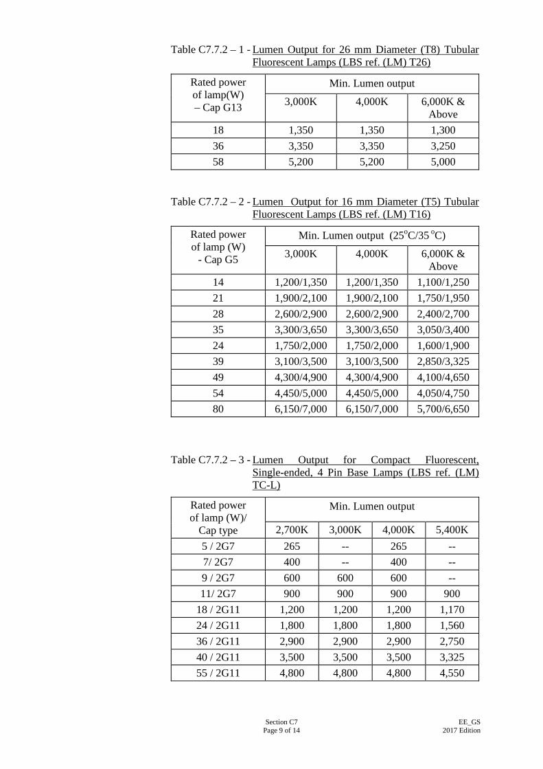
Section C7 Page 9 of 14
EE_GS 2017 Edition
Table C7.7.2 – 1 - Lumen Output for 26 mm Diameter (T8) Tubular Fluorescent Lamps (LBS ref. (LM) T26)
Rated power of lamp(W) – Cap G13
Min. Lumen output
3,000K 4,000K 6,000K & Above
18 1,350 1,350 1,300 36 3,350 3,350 3,250 58 5,200 5,200 5,000
Table C7.7.2 – 2 - Lumen Output for 16 mm Diameter (T5) Tubular
Fluorescent Lamps (LBS ref. (LM) T16)
Rated power of lamp (W)
- Cap G5
Min. Lumen output (25oC/35 oC)
3,000K 4,000K 6,000K & Above
14 1,200/1,350 1,200/1,350 1,100/1,250 21 1,900/2,100 1,900/2,100 1,750/1,950 28 2,600/2,900 2,600/2,900 2,400/2,700 35 3,300/3,650 3,300/3,650 3,050/3,400 24 1,750/2,000 1,750/2,000 1,600/1,900 39 3,100/3,500 3,100/3,500 2,850/3,325 49 4,300/4,900 4,300/4,900 4,100/4,650 54 4,450/5,000 4,450/5,000 4,050/4,750 80 6,150/7,000 6,150/7,000 5,700/6,650
Table C7.7.2 – 3 - Lumen Output for Compact Fluorescent, Single-ended, 4 Pin Base Lamps (LBS ref. (LM) TC-L)
Rated power of lamp (W)/
Cap type
Min. Lumen output
2,700K 3,000K 4,000K 5,400K 5 / 2G7 265 -- 265 -- 7/ 2G7 400 -- 400 -- 9 / 2G7 600 600 600 -- 11/ 2G7 900 900 900 900
18 / 2G11 1,200 1,200 1,200 1,170 24 / 2G11 1,800 1,800 1,800 1,560 36 / 2G11 2,900 2,900 2,900 2,750 40 / 2G11 3,500 3,500 3,500 3,325 55 / 2G11 4,800 4,800 4,800 4,550
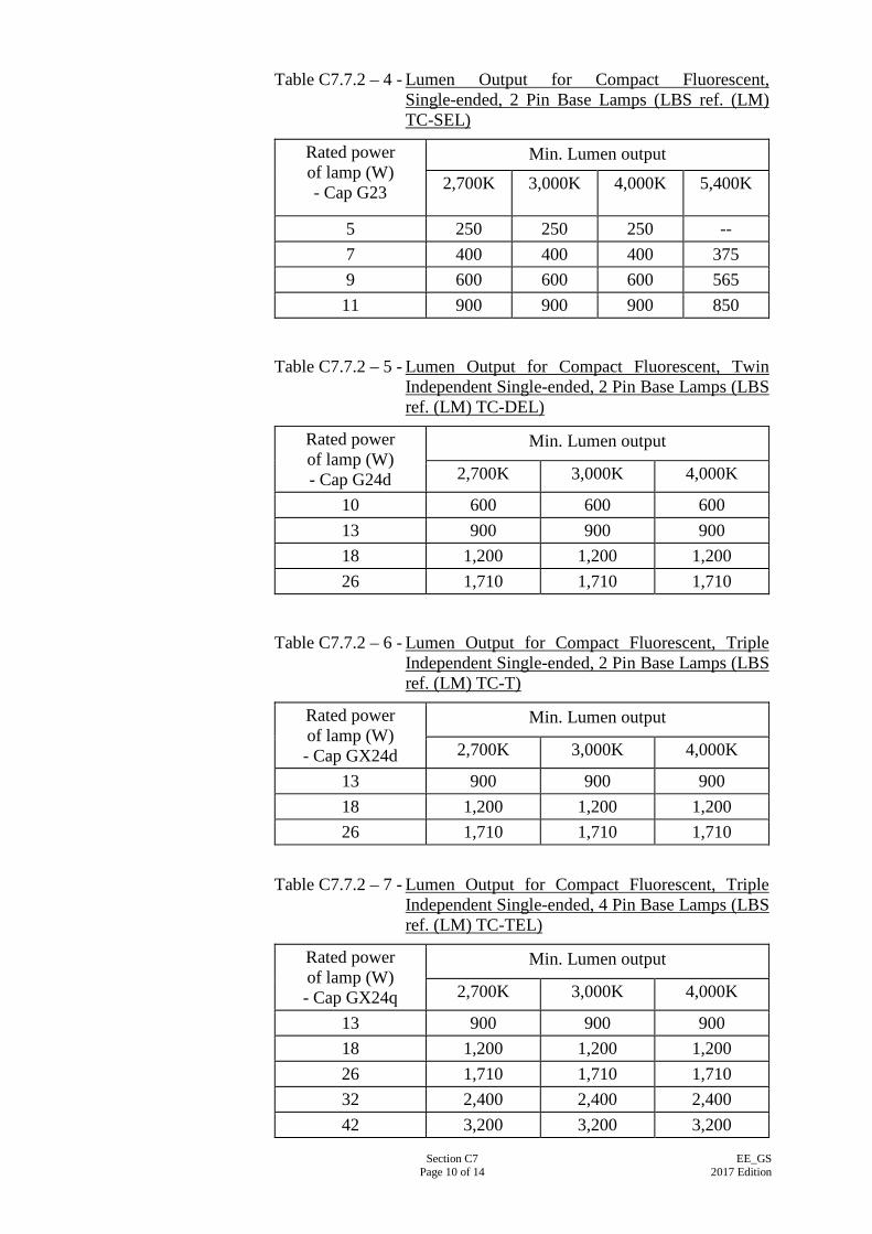
Section C7 Page 10 of 14
EE_GS 2017 Edition
Table C7.7.2 – 4 - Lumen Output for Compact Fluorescent, Single-ended, 2 Pin Base Lamps (LBS ref. (LM) TC-SEL)
Rated power of lamp (W) - Cap G23
Min. Lumen output
2,700K 3,000K 4,000K 5,400K
5 250 250 250 -- 7 400 400 400 375 9 600 600 600 565 11 900 900 900 850
Table C7.7.2 – 5 - Lumen Output for Compact Fluorescent, Twin Independent Single-ended, 2 Pin Base Lamps (LBS ref. (LM) TC-DEL)
Rated power of lamp (W) - Cap G24d
Min. Lumen output
2,700K 3,000K 4,000K
10 600 600 600 13 900 900 900 18 1,200 1,200 1,200 26 1,710 1,710 1,710
Table C7.7.2 – 6 - Lumen Output for Compact Fluorescent, Triple Independent Single-ended, 2 Pin Base Lamps (LBS ref. (LM) TC-T)
Rated power of lamp (W) - Cap GX24d
Min. Lumen output
2,700K 3,000K 4,000K
13 900 900 900 18 1,200 1,200 1,200 26 1,710 1,710 1,710
Table C7.7.2 – 7 - Lumen Output for Compact Fluorescent, Triple Independent Single-ended, 4 Pin Base Lamps (LBS ref. (LM) TC-TEL)
Rated power of lamp (W) - Cap GX24q
Min. Lumen output
2,700K 3,000K 4,000K
13 900 900 900 18 1,200 1,200 1,200 26 1,710 1,710 1,710 32 2,400 2,400 2,400 42 3,200 3,200 3,200
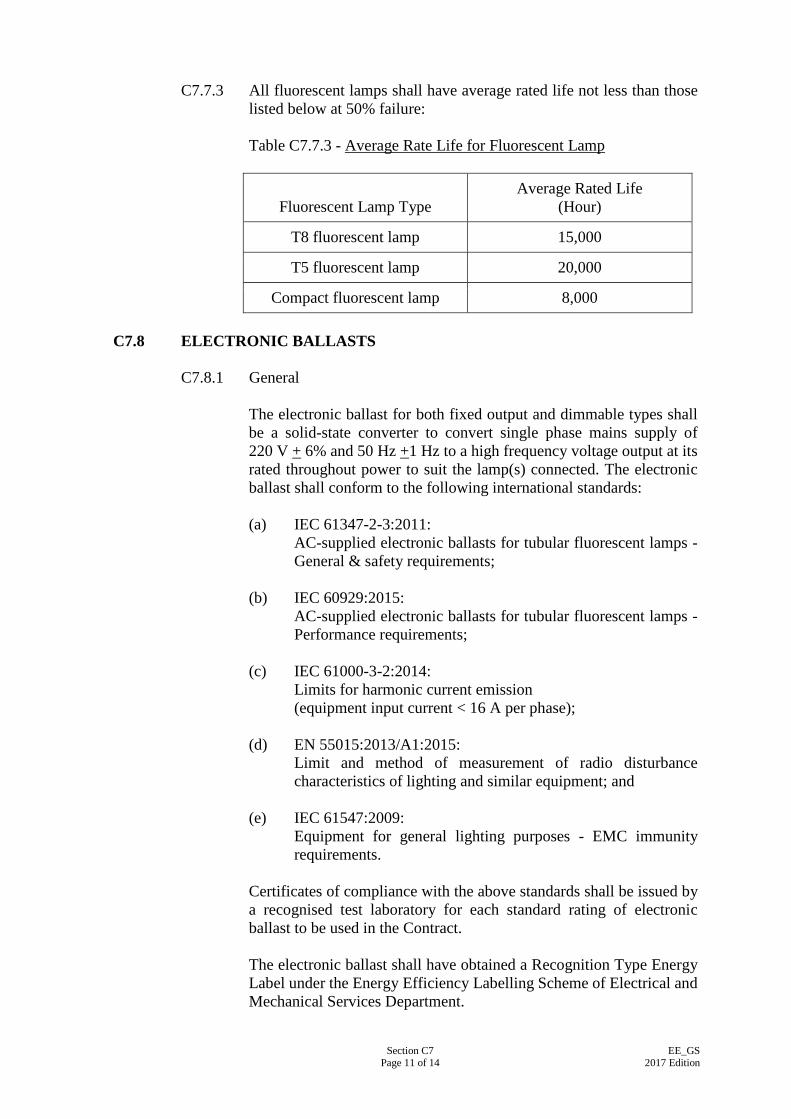
Section C7 Page 11 of 14
EE_GS 2017 Edition
C7.7.3 All fluorescent lamps shall have average rated life not less than those
listed below at 50% failure: Table C7.7.3 - Average Rate Life for Fluorescent Lamp
Fluorescent Lamp Type
Average Rated Life (Hour)
T8 fluorescent lamp 15,000
T5 fluorescent lamp 20,000
Compact fluorescent lamp 8,000 C7.8 ELECTRONIC BALLASTS
C7.8.1 General
The electronic ballast for both fixed output and dimmable types shall be a solid-state converter to convert single phase mains supply of 220 V + 6% and 50 Hz +1 Hz to a high frequency voltage output at its rated throughout power to suit the lamp(s) connected. The electronic ballast shall conform to the following international standards: (a) IEC 61347-2-3:2011:
AC-supplied electronic ballasts for tubular fluorescent lamps - General & safety requirements;
(b) IEC 60929:2015:
AC-supplied electronic ballasts for tubular fluorescent lamps - Performance requirements;
(c) IEC 61000-3-2:2014:
Limits for harmonic current emission (equipment input current < 16 A per phase);
(d) EN 55015:2013/A1:2015:
Limit and method of measurement of radio disturbance characteristics of lighting and similar equipment; and
(e) IEC 61547:2009:
Equipment for general lighting purposes - EMC immunity requirements.
Certificates of compliance with the above standards shall be issued by a recognised test laboratory for each standard rating of electronic ballast to be used in the Contract. The electronic ballast shall have obtained a Recognition Type Energy Label under the Energy Efficiency Labelling Scheme of Electrical and Mechanical Services Department.
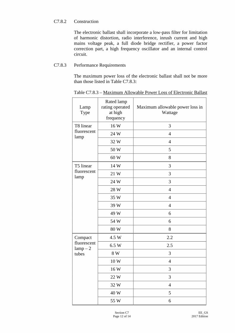
Section C7 Page 12 of 14
EE_GS 2017 Edition
C7.8.2 Construction The electronic ballast shall incorporate a low-pass filter for limitation of harmonic distortion, radio interference, inrush current and high mains voltage peak, a full diode bridge rectifier, a power factor correction part, a high frequency oscillator and an internal control circuit.
C7.8.3 Performance Requirements The maximum power loss of the electronic ballast shall not be more than those listed in Table C7.8.3: Table C7.8.3 – Maximum Allowable Power Loss of Electronic Ballast
Lamp Type
Rated lamp rating operated
at high frequency
Maximum allowable power loss in Wattage
T8 linear fluorescent lamp
16 W 3
24 W 4
32 W 4
50 W 5
60 W 8
T5 linear fluorescent lamp
14 W 3
21 W 3
24 W 3
28 W 4
35 W 4
39 W 4
49 W 6
54 W 6
80 W 8
Compact fluorescent lamp – 2 tubes
4.5 W 2.2
6.5 W 2.5
8 W 3
10 W 4
16 W 3
22 W 3
32 W 4
40 W 5
55 W 6
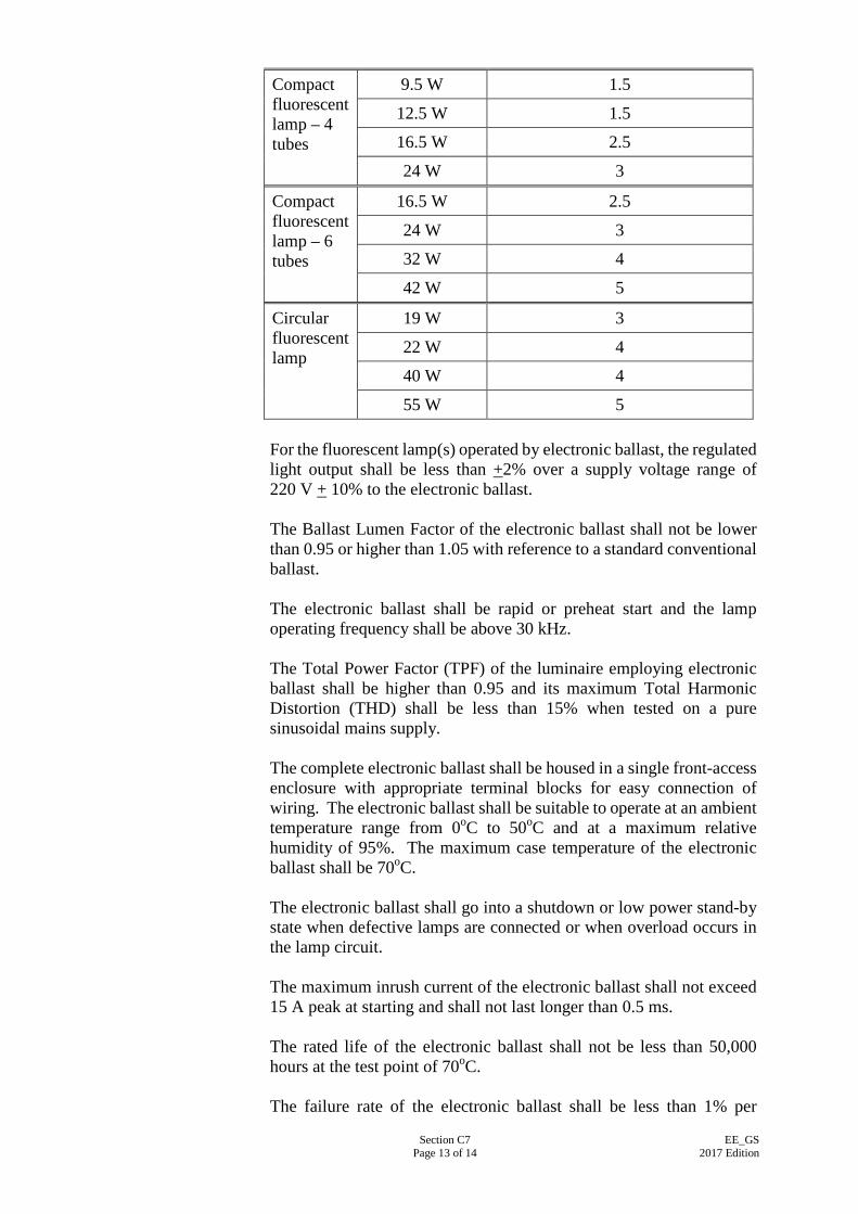
Section C7 Page 13 of 14
EE_GS 2017 Edition
Compact fluorescent lamp – 4 tubes
9.5 W 1.5
12.5 W 1.5
16.5 W 2.5
24 W 3
Compact fluorescent lamp – 6 tubes
16.5 W 2.5
24 W 3
32 W 4
42 W 5
Circular fluorescent lamp
19 W 3
22 W 4
40 W 4
55 W 5 For the fluorescent lamp(s) operated by electronic ballast, the regulated light output shall be less than +2% over a supply voltage range of 220 V + 10% to the electronic ballast. The Ballast Lumen Factor of the electronic ballast shall not be lower than 0.95 or higher than 1.05 with reference to a standard conventional ballast. The electronic ballast shall be rapid or preheat start and the lamp operating frequency shall be above 30 kHz. The Total Power Factor (TPF) of the luminaire employing electronic ballast shall be higher than 0.95 and its maximum Total Harmonic Distortion (THD) shall be less than 15% when tested on a pure sinusoidal mains supply. The complete electronic ballast shall be housed in a single front-access enclosure with appropriate terminal blocks for easy connection of wiring. The electronic ballast shall be suitable to operate at an ambient temperature range from 0oC to 50oC and at a maximum relative humidity of 95%. The maximum case temperature of the electronic ballast shall be 70oC. The electronic ballast shall go into a shutdown or low power stand-by state when defective lamps are connected or when overload occurs in the lamp circuit. The maximum inrush current of the electronic ballast shall not exceed 15 A peak at starting and shall not last longer than 0.5 ms. The rated life of the electronic ballast shall not be less than 50,000 hours at the test point of 70oC. The failure rate of the electronic ballast shall be less than 1% per

Section C7 Page 14 of 14
EE_GS 2017 Edition
4,000 hours operation at the maximum case temperature.
C7.8.4 Additional Requirements for Dimmable Electronic Ballasts Electronic ballasts with dimmable function shall meet the following additional requirements: (a) high energy efficient dimming system providing continuous
dimming range of 5% - 100%; (b) the electronic ballast shall be compatible with the dimming
circuit provided; (c) dimming performance shall follow logarithmic characteristics
that is optimised according to the sensitivity of human eye; and (d) provide flicker-free dimming operation throughout the
complete operation temperature range.
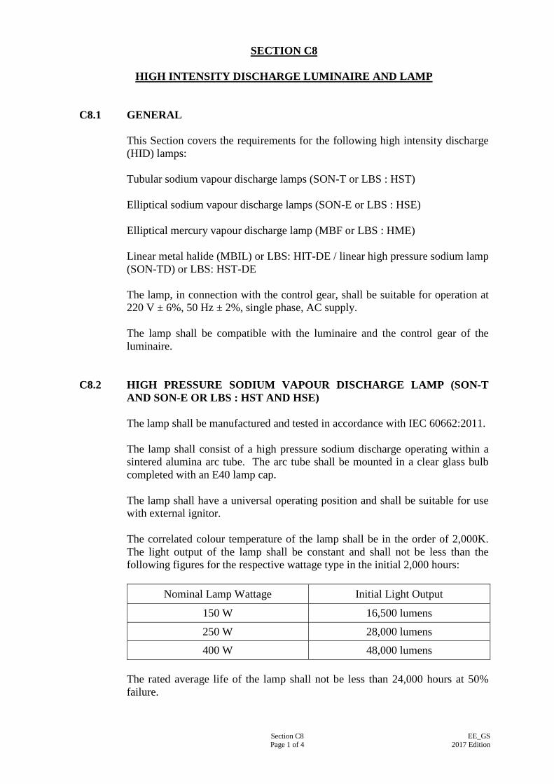
Section C8 Page 1 of 4
EE_GS 2017 Edition
SECTION C8
HIGH INTENSITY DISCHARGE LUMINAIRE AND LAMP
C8.1 GENERAL This Section covers the requirements for the following high intensity discharge (HID) lamps: Tubular sodium vapour discharge lamps (SON-T or LBS : HST) Elliptical sodium vapour discharge lamps (SON-E or LBS : HSE) Elliptical mercury vapour discharge lamp (MBF or LBS : HME) Linear metal halide (MBIL) or LBS: HIT-DE / linear high pressure sodium lamp (SON-TD) or LBS: HST-DE The lamp, in connection with the control gear, shall be suitable for operation at 220 V ± 6%, 50 Hz ± 2%, single phase, AC supply. The lamp shall be compatible with the luminaire and the control gear of the luminaire.
C8.2 HIGH PRESSURE SODIUM VAPOUR DISCHARGE LAMP (SON-T AND SON-E OR LBS : HST AND HSE) The lamp shall be manufactured and tested in accordance with IEC 60662:2011. The lamp shall consist of a high pressure sodium discharge operating within a sintered alumina arc tube. The arc tube shall be mounted in a clear glass bulb completed with an E40 lamp cap. The lamp shall have a universal operating position and shall be suitable for use with external ignitor. The correlated colour temperature of the lamp shall be in the order of 2,000K. The light output of the lamp shall be constant and shall not be less than the following figures for the respective wattage type in the initial 2,000 hours:
Nominal Lamp Wattage Initial Light Output
150 W 16,500 lumens
250 W 28,000 lumens
400 W 48,000 lumens The rated average life of the lamp shall not be less than 24,000 hours at 50% failure.
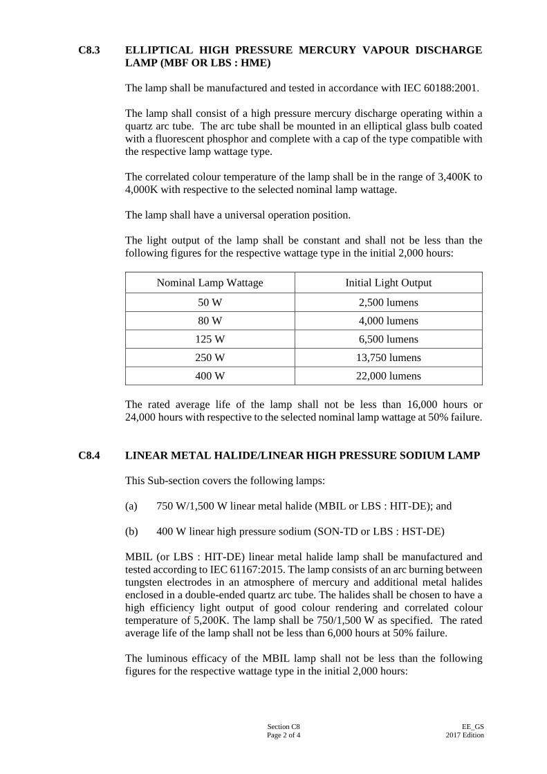
Section C8 Page 2 of 4
EE_GS 2017 Edition
C8.3 ELLIPTICAL HIGH PRESSURE MERCURY VAPOUR DISCHARGE LAMP (MBF OR LBS : HME) The lamp shall be manufactured and tested in accordance with IEC 60188:2001. The lamp shall consist of a high pressure mercury discharge operating within a quartz arc tube. The arc tube shall be mounted in an elliptical glass bulb coated with a fluorescent phosphor and complete with a cap of the type compatible with the respective lamp wattage type. The correlated colour temperature of the lamp shall be in the range of 3,400K to 4,000K with respective to the selected nominal lamp wattage. The lamp shall have a universal operation position. The light output of the lamp shall be constant and shall not be less than the following figures for the respective wattage type in the initial 2,000 hours:
Nominal Lamp Wattage Initial Light Output
50 W 2,500 lumens
80 W 4,000 lumens
125 W 6,500 lumens
250 W 13,750 lumens
400 W 22,000 lumens The rated average life of the lamp shall not be less than 16,000 hours or 24,000 hours with respective to the selected nominal lamp wattage at 50% failure.
C8.4 LINEAR METAL HALIDE/LINEAR HIGH PRESSURE SODIUM LAMP
This Sub-section covers the following lamps: (a) 750 W/1,500 W linear metal halide (MBIL or LBS : HIT-DE); and (b) 400 W linear high pressure sodium (SON-TD or LBS : HST-DE) MBIL (or LBS : HIT-DE) linear metal halide lamp shall be manufactured and tested according to IEC 61167:2015. The lamp consists of an arc burning between tungsten electrodes in an atmosphere of mercury and additional metal halides enclosed in a double-ended quartz arc tube. The halides shall be chosen to have a high efficiency light output of good colour rendering and correlated colour temperature of 5,200K. The lamp shall be 750/1,500 W as specified. The rated average life of the lamp shall not be less than 6,000 hours at 50% failure. The luminous efficacy of the MBIL lamp shall not be less than the following figures for the respective wattage type in the initial 2,000 hours:
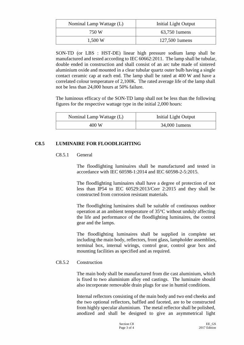
Section C8 Page 3 of 4
EE_GS 2017 Edition
Nominal Lamp Wattage (L) Initial Light Output
750 W 63,750 1umens
1,500 W 127,500 1umens SON-TD (or LBS : HST-DE) linear high pressure sodium lamp shall be manufactured and tested according to IEC 60662:2011. The lamp shall be tubular, double ended in construction and shall consist of an arc tube made of sintered aluminium oxide and mounted in a clear tubular quartz outer bulb having a single contact ceramic cap at each end. The lamp shall be rated at 400 W and have a correlated colour temperature of 2,100K. The rated average life of the lamp shall not be less than 24,000 hours at 50% failure. The luminous efficacy of the SON-TD lamp shall not be less than the following figures for the respective wattage type in the initial 2,000 hours:
Nominal Lamp Wattage (L) Initial Light Output
400 W 34,000 1umens
C8.5 LUMINAIRE FOR FLOODLIGHTING C8.5.1 General
The floodlighting luminaires shall be manufactured and tested in accordance with IEC 60598-1:2014 and IEC 60598-2-5:2015. The floodlighting luminaires shall have a degree of protection of not less than IP54 to IEC 60529:2013/Corr 2:2015 and they shall be constructed from corrosion resistant materials. The floodlighting luminaires shall be suitable of continuous outdoor operation at an ambient temperature of 35°C without unduly affecting the life and performance of the floodlighting luminaires, the control gear and the lamps. The floodlighting luminaires shall be supplied in complete set including the main body, reflectors, front glass, lampholder assemblies, terminal box, internal wirings, control gear, control gear box and mounting facilities as specified and as required.
C8.5.2 Construction The main body shall be manufactured from die cast aluminium, which is fixed to two aluminium alloy end castings. The luminaire should also incorporate removable drain plugs for use in humid conditions. Internal reflectors consisting of the main body and two end cheeks and the two optional reflectors, baffled and faceted, are to be constructed from highly specular aluminium. The metal reflector shall be polished, anodized and shall be designed to give an asymmetrical light
Section C8 Page 4 of 4
EE_GS 2017 Edition
distribution of beam angle to 1/10 peak to approximately the following requirements: (a) for 750/1,500 W MBIL (or LBS : HIT-DE) lamp
Horizontal 90° Vertical 9° above peak, 41° below peak; and
(b) for 400 W SON-TD (or LBS : HST : DE) lamp
Horizontal 84° Vertical 4° above peak, 19° below peak.
The heat resistant toughened glass shall be fitted to a non-ferrous metal front frame with corrosion resistant hinges and four swivel bolts (stainless steel) for securing to the main body and provided with weatherproofing silicon rubber gasket between the main body and toughened front glass. The lampholder assembly shall be suitable for accepting the lamp as specified. They shall be incorporated with appropriate heat sinks if necessary to avoid overheating. Weatherproof wiring terminal box shall be mounted at the rear side of the main body suitable for housing a two-way terminal block, each terminal suitable for 1x10 mm2 cable. Cable entry is provided via a combined cable gland/cord grip. Earthing stud/terminal shall be provided. Internal wiring shall be of heat resistant type to the appropriate IEC Standard. The control gear shall be suitable for operation of the lamp as specified, and shall consist of a ballast, ignitor, transformer and power factor correction capacitor(s) as appropriate, to enable the whole assembly to operate at the specified voltage with an overall power factor not less than 0.85. Control gear shall be provided with facilities for easy and securely fixing to a metal back plate or gear box. Control gear shall be suitable for continuous operation under an ambient temperature of 35°C. The floodlighting luminaires shall be complete with the stirrup arrangement which permits the floodlighting luminaires to be rotated in azimuth and adjusted in elevation. An aiming stop shall be provided on the floodlighting luminaires to ensure that the aiming angle remains undisturbed even if the floodlighting luminaires are removed from the stirrup for servicing.
C8.5.3 Lamps All types of lamps suitable for fixing to the specified luminaire shall have a high efficiency and a fairly constant output and be constructed with appropriate lamp caps.
Section C9 Page 1 of 5
EE_GS 2017 Edition
SECTION C9
LIGHT EMITTING DIODE LUMINAIRE & DRIVER
C9.1 GENERAL C9.1.1 The ‘Light Emitting Diode’ (LED) luminaires, including the electronic
driver and LED module shall be suitable for operation at 220 V ± 6%, 50 Hz ± 2%, single phase AC supply.
C9.1.2 The LED luminaires shall be fully assembled and tested before
shipment from factory. The LED luminaire shall comply with the following international standards and their manufacturing process shall conform to the relevant quality standard of ISO 9001:2008:
IEC 60598-1:2014 IEC 60598-2-1:1987 IEC 60598-2-2:2011 IEC 60598-2-3:2011 IEC 60598-2-5:2015 IEC 60598-2-13: 2012 IEC 60598-2-22: 2014 IEC 62722 – 1:2014 IEC 62722-2-1: 2014
: : : : : : : : :
Luminaires – Part 1: General requirements and tests; and Luminaires – Part 2: Particular requirements. Section 1: Fixed general purpose luminaires; or Luminaires – Part 2 Particular requirements. Section 2: Recessed luminaries; or Luminaires – Part 2 Particular Requirements Section 3: Luminaries for road and street lighting; or Luminaires – Part 2 Particular Requirements Section 5: Floodlights Luminaires – Part 2 Particular Requirements Section 13: Ground recessed luminaires Luminaires – Part 2 Particular Requirements Section 22: Luminaires for emergency lighting Luminaires Performance – Part 1: General Requirements Luminaires Performance – Part 2.1: Particular Requirements for LED Luminaires
Type test certificate shall be provided to demonstrate the compliance with the above standards issued by an accredited test laboratory for the LED luminaries.
Section C9 Page 2 of 5
EE_GS 2017 Edition
C9.1.3 The LED luminaires shall be marked in accordance with the
requirements of IEC 60598-2-1:1987 for general-purpose luminaires or IEC 60598-2-2:1997 for recessed luminaries. The ingress protection for indoor and outdoor LED luminaire shall be at least IP2X and IP54 respectively to IEC 60529:2013/Corr 2:2015.
C9.1.4 The irradiance and radiance emission limits of the LED luminaires,
that are exposed to view directly, shall be tested to comply with the hazard ‘Risk Group 1’ (low risk) as stated in the requirements of the IEC 62471:2006 – Photobiological safety of lamps and lamp systems.
C9.1.5 The LED luminaires shall be rated for continuous service at an ambient
temperature of 40 oC without affecting the performance requirements as stated in clause C9.4 of this specification. The EE Contractor shall be responsible to advise the Supervising Officer if the performance of the LED luminaires will be affected by the installation conditions.
C9.1.6 The LED luminaires shall be ‘Restriction of Hazardous Substances
(RoHS) Compliance’. C9.1.7 The LED luminaires shall have a full set of photometric data prepared
to CIBSE TM5 or IES format for general lighting design purpose.
C9.2 ELECTRONIC DRIVER C9.2.1 The electronic driver (driver) for the LED luminaire shall include the
components of power factor correction, radio interference suppression and also dimming facility if it is specified. The driver shall conform to the following international standards if applicable:
EN 55015:2009 IEC 61000-3-2: 2009 IEC 61347-1:2007 IEC 61347-2-13:2006 IEC 61547:2009
: : : : :
Limits and methods of measurement of radio disturbance characteristics of electrical lighting and similar equipment. Electromagnetic compatibility (EMC) – Part 3-2: Limits – Limits for harmonic current emissions (equipment input current ≦ 16 A per phase); Lamp controlgear – Part 1: General and safety requirements; Lamp controlgear – Part 2-13: Particular requirements for DC or AC supplied electronic controlgear for LED modules; Equipment for general lighting purposes – EMC immunity requirements; and
Section C9 Page 3 of 5
EE_GS 2017 Edition
IEC 62384:20011
:
DC or AC supplied electronic control gear for LED modules – Performance requirements;
Certificates of compliance issued by accredited test laboratories shall be provided for different ratings of drivers to be used in the Contract.
C9.2.2 Technical information of the drivers shall be provided to indicate the
performance of the drivers. The data shall include, but not limited to, minimum and maximum input voltage, frequency, maximum operating temperature, rated output voltage, rated output current, rated output power and power factor.
C9.2.3 The rated life of driver shall not be less than 35,000 hours operating at
ambient temperature not lower than 40°C. C9.2.4 Electronic ballast shall be compatible with the dimming circuit
provided. Unless other specified, the electronic ballast shall have at least continuous dimming range 40% - 100% without flickering.
C9.3 LED MODULE
C9.3.1 The LED module, self-ballasted LED module or self-ballasted LED lamp shall be manufactured and tested to comply with the following standards if applicable:
LED module & Self-ballasted LED module
: IEC 62031:2014: LED modules for general lighting – Safety specifications.
Connector for LED modules
: IEC 60838-2-2:2012: Miscellaneous lampholders – Part 2-2: Particular requirements – Connectors for LED modules
Certificate of compliance with the above standards shall be issued by an accredited test laboratory or the manufacturer of LED module.
C9.4 PERFORMANCE REQUIREMENTS
C9.4.1 The performance of the LED luminaire and self-ballasted LED lamp shall comply with the following requirements:
(a) Luminaire efficacy (lumen/watt):
The luminaire efficacy of different types of luminaires under different colour temperatures to be used in the Contract shall be provided to indicate its performance.
Section C9 Page 4 of 5
EE_GS 2017 Edition
(b) Lumen maintenance (L70)
The lumen output of LED luminaire shall deliver at least 70% of its initial lumen output after operating 35,000 hours and 25,000 hours for LED luminaire and self-ballasted LED lamp respectively. For compliance with the L70 threshold lumen maintenance requirements, the lumen maintenance data of each colour temperature LED luminaire using 6,000 hours is acceptable for projecting the L70. The required lumen maintenance at 6,000 hours shall not be less than 94.1% and 91.8% for L70 = 35,000 hours and L70 = 25,000 hours respectively.
(c) Colour Rendering Index (CRI):
CRI shall be minimum 80 for colour temperature from 2,700 – 6,000K for indoor luminaires and self-ballasted LED lamp.
(d) Power factor:
The power factor of the LED luminaire circuit and self-ballasted LED lamp shall be minimum 0.9 and minimum 0.7 respectively.
(e) Correlated Colour Temperature (CCT) and its tolerance limit:
The colour temperature of a group of LED luminaires in the same space or room shall not be visually noticeable. The nominal CCT of the LED light source shall preferrably be one of the following values. The tolerance limits shall be within the below ranges: 2,700 K 2,725 ± 145 K
3,000 K 3,045 ± 175 K
3,500 K 3,465 ± 245 K
4,000 K 3,985 ± 275 K
5,700 K 5,665 ± 355 K
6,500K 6,530 ± 510 K
C9.4.2 Each model of LED luminaire or self-ballasted LED lamp shall be
tested to comply with the above performance requirements. The EE Contractor shall submit the test report from the accredited laboratories to certify each model of LED luminaire or self-ballasted LED lamp complying with the standards or other recognised international/national standards or other standards proposed by the EE Contractor and agreed by the Supervising Officer.
C9.4.3 Self-ballasted LED lamps for general lighting services shall comply with the following requirement;
Section C9 Page 5 of 5
EE_GS 2017 Edition
(a) IEC 62560: 2011: Self-ballasted LED lamps for general
lighting services by voltage>50V – Safety specification; and (b) IEC,62612 – Self-ballasted LED lamps for general lighting
services with supply voltages > 50 V - Performance Requirements.
C9.4.4. For double-capped LED tubular lamp designed to retrofit tubular
fluorescent lamp, the LED lamp shall comply with IEC62776 “Double-capped LED Lamps Designed to retrofit linear fluorescent lamps – Safety Specifications”.
Section C10 Page 1 of 49
EE_GS 2017 Edition
SECTION C10
DOMESTIC APPLIANCES
C10.1 GENERAL C10.1.1 Compliance with Regulation
Domestic appliances together with their electric components and cabling shall comply with the currently-in-forced edition of (a) Electrical Products (Safety) Regulation, (Cap.406G), Laws of
Hong Kong; and (b) IEC 60335-1:2013 Household and similar electrical
appliances – Safety – Part 1 : General requirements.
C10.1.2 General Requirements (a) Unless otherwise specified, the domestic appliances shall be
designed for operation on 220 V + 10%, 50 Hz +2%, single phase, AC supply.
(b) Unless otherwise specified, the domestic appliances shall be
suitable in all respects for operation in ambient air condition of temperature range between 0°C and 40°C, and relative humidity range between 0% and 99% with condensation due to temperature changes.
(c) Unless otherwise classified, all accessible metal parts of the
domestic appliances that may become live in the event of electric fault shall be effectively and suitably bonded to earth via to a common earthing terminal provided within the domestic appliances.
(d) Twin core cables without earth wire are only allowed for double
insulated appliances classified as Class II appliances under the specified IEC or equivalent standards.
(e) Where specified, 3-core flexible cord connected to the domestic
appliances shall conform to BS EN50525-2-11:2011. The size of the cable shall not be less than that specified and shall be compatible with the rating of the respective domestic appliance. Twin core cables without earth wire are only allowed for double insulated appliances.
(f) Where specified, 13 A plug connected to the flexible cord shall
conform to BS 1363-1:1995. The fuse of the plug shall be of a rating compatible with the rating of the respective domestic appliance.
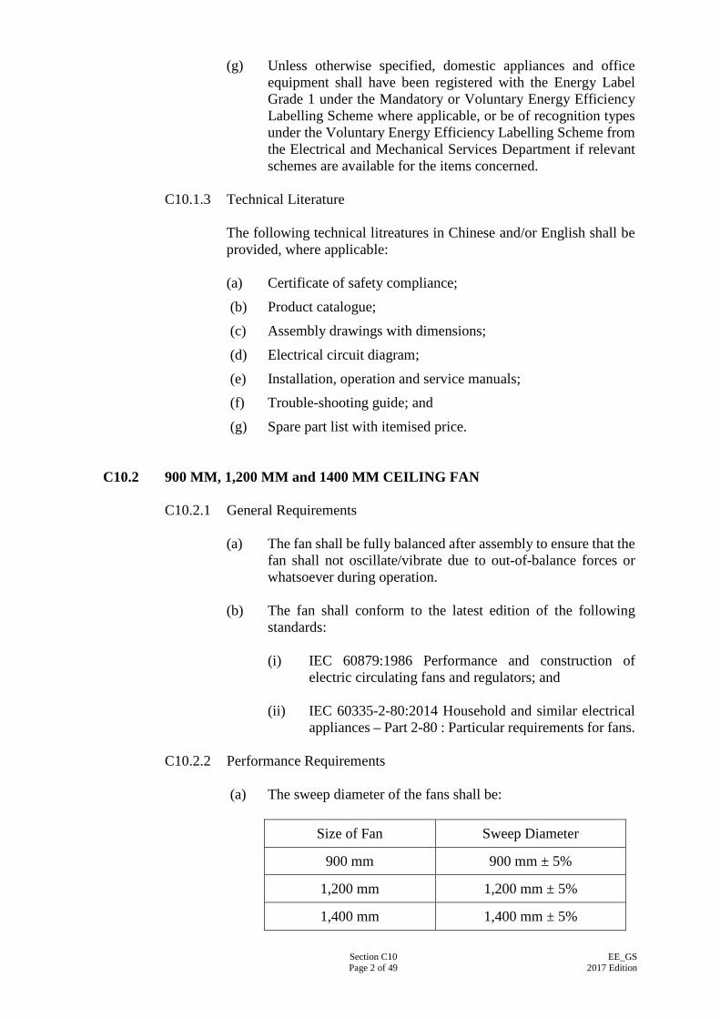
Section C10 Page 2 of 49
EE_GS 2017 Edition
(g) Unless otherwise specified, domestic appliances and office equipment shall have been registered with the Energy Label Grade 1 under the Mandatory or Voluntary Energy Efficiency Labelling Scheme where applicable, or be of recognition types under the Voluntary Energy Efficiency Labelling Scheme from the Electrical and Mechanical Services Department if relevant schemes are available for the items concerned.
C10.1.3 Technical Literature
The following technical litreatures in Chinese and/or English shall be provided, where applicable: (a) Certificate of safety compliance;
(b) Product catalogue;
(c) Assembly drawings with dimensions;
(d) Electrical circuit diagram;
(e) Installation, operation and service manuals; (f) Trouble-shooting guide; and
(g) Spare part list with itemised price.
C10.2 900 MM, 1,200 MM and 1400 MM CEILING FAN
C10.2.1 General Requirements (a) The fan shall be fully balanced after assembly to ensure that the
fan shall not oscillate/vibrate due to out-of-balance forces or whatsoever during operation.
(b) The fan shall conform to the latest edition of the following
standards: (i) IEC 60879:1986 Performance and construction of
electric circulating fans and regulators; and
(ii) IEC 60335-2-80:2014 Household and similar electrical appliances – Part 2-80 : Particular requirements for fans.
C10.2.2 Performance Requirements
(a) The sweep diameter of the fans shall be:
Size of Fan Sweep Diameter
900 mm 900 mm ± 5%
1,200 mm 1,200 mm ± 5%
1,400 mm 1,400 mm ± 5%
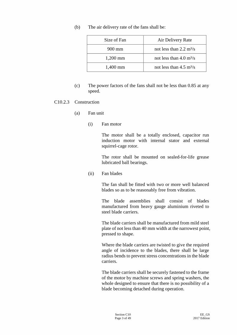
Section C10 Page 3 of 49
EE_GS 2017 Edition
(b) The air delivery rate of the fans shall be:
Size of Fan Air Delivery Rate
900 mm not less than 2.2 m³/s
1,200 mm not less than 4.0 m³/s
1,400 mm not less than 4.5 m³/s (c) The power factors of the fans shall not be less than 0.85 at any
speed.
C10.2.3 Construction (a) Fan unit
(i) Fan motor The motor shall be a totally enclosed, capacitor run induction motor with internal stator and external squirrel-cage rotor. The rotor shall be mounted on sealed-for-life grease lubricated ball bearings.
(ii) Fan blades The fan shall be fitted with two or more well balanced blades so as to be reasonably free from vibration. The blade assemblies shall consist of blades manufactured from heavy gauge aluminium riveted to steel blade carriers. The blade carriers shall be manufactured from mild steel plate of not less than 40 mm width at the narrowest point, pressed to shape. Where the blade carriers are twisted to give the required angle of incidence to the blades, there shall be large radius bends to prevent stress concentrations in the blade carriers. The blade carriers shall be securely fastened to the frame of the motor by machine screws and spring washers, the whole designed to ensure that there is no possibility of a blade becoming detached during operation.

Section C10 Page 4 of 49
EE_GS 2017 Edition
(b) Connecting piece (capacitor housing) (i) The plastic terminal block and capacitor shall be
mounted in a ferrous metal connecting piece located between the fan and the down-rod assembly. The leads from the stator windings shall be connected to the terminal block. An earthing terminal, consisting of a round head brass screw and washer, shall be provided on the connecting piece. All exposed metal parts of the fan shall be connected to this earthing terminal.
(ii) The bottom portion of the connecting piece shall be
screwed on the shaft of the motor. The connecting piece shall be tightened on to a shoulder formed on the motor shaft. A 4 mm minimum thickness steel hexagonal lock-nut with lock bracket underneath shall then be fitted and tightened. The connecting piece shall be secured in the fully tightened position by two (2) hardened steel grub screws. These screws shall engage in shallow depressions drilled in the shaft after the connecting piece has been tightened in place to ensure positive locking.
(c) Down-rod assembly
(i) The down-rod assembly shall consist of a steel down-rod
complete with shackle and hard rubber roller for suspension of the fan. The down-rod shall be supplied in lengths of 200 mm, 300 mm, 450 mm, 600 mm, 750 mm, 900 mm and 1,200 mm as specified in the Particular Specification.
(ii) Cable of such a length as to suit the down-rod shall be
provided. The down-rod shall be manufactured from steel tube to BS EN 10255:2004, having an outside diameter of approximately 21 mm, with minimum wall thickness of not less than 3 mm as specified in Table 5 of BS EN 10255:2004. It shall be accurately threaded at one end and shall be screwed into the top portion of the fan connecting piece (capacitor housing) from which it shall protrude by a minimum of 2 mm. The minimum wall thickness of the threaded portion, measured from the minor diameter of the thread to the internal diameter of the tube, shall be not less than 1.8 mm.
(iii) The down-rod shall be locked in position by two (2)
hexagonal steel lock nuts, having a minimum thickness of 6 mm, tightened on to the upper machined surface of the fan connecting piece.
(iv) The down-rod shall also be locked to the fan connecting
piece by means of a steel split-pin, of not less than 5 mm
Section C10 Page 5 of 49
EE_GS 2017 Edition
diameter, passing through both the fan connecting piece and the down-rod.
(v) The split-pin holes in the fan connecting piece shall be of
such diameter that the split-pin is a light push-fit there in. The matching split-pin holes in the down-rod shall be just sufficiently large so that the split-pin shall be a light push-fit, when the hole is in its worst position relative to the threading. All burrs and sharp edges shall be removed from the split-pin holes in both the fan connecting piece and the down-rod.
(vi) The steel suspension shackle shall be welded to the
down-rod. Welding shall be of good quality. The rubber roller shall be mounted on an 8 mm diameter steel clevis pin secured by a split-pin.
(vii) The ends of the down-rod shall rounded off and free
from burrs. There shall be no sharp edges which could cause damage to the insulation of the wiring.
(viii) Suspension joints and threaded parts:
Joints along the suspension rod must be of double-locking design, i.e. at least two independent positive locking devices must be employed to prevent a joint from loosening itself. All factory-assembled threaded components which form part of a suspension joint must be bonded with glue as approved by the Supervising Officer. The maximum clearance between threaded mating parts must not exceed 1% of their mean diameter. The direction of rotation of the fan shall be such that all screwed joints tend to be tightened when the fan is in operation.
(ix) Two (2) canopies manufactured from plastic or pressed steel sheet and fitted over the upper and lower ends of the down-rod shall be provided. They shall be fixed to the down-rod by grub screws.
(d) Surface finish
The whole fan shall be finished in high quality stove enamel in white or ivory colour.
(e) Speed regulator (i) A speed regulator shall be supplied with each fan.
Section C10 Page 6 of 49
EE_GS 2017 Edition
(ii) The speed regulator shall be of robust construction and
built on a flame-retardant moulded plastic or insulated steel base and enclosed by a flame-retardant moulded plastic cover or metal cover. Plastic cover shall be in white or ivory colour to match the fan. Metal cover shall be of stainless steel or metalclad finish.
(iii) The speed regulator shall be equipped with at least three
(3) speed controls and an “OFF” position. (iv) The rotary switch of the speed regulator shall be
designed for smooth and easy movement by hand between different speed positions.
(v) For choke type regulator, an earth terminal shall be
provided on the base with an earth wire permanently connected to the steel core of the choke unit.
C10.3 400 MM SWEEP AUTO CYCLE/OSCILLATING FAN C10.3.1 General Requirements
(a) The fan shall be provided with cable entries, conduit opening or glands for permanent connection to fixed wiring. Connection terminal shall be provided and secured by means of screws, nuts or equally effective devices.
(b) The power factor of the fan shall not be less than 0.8. (c) The fan shall comply with the latest edition of safety standards
for household electric fans and regulators as follows:
(i) IEC 60335-2-80:2015; and
(ii) JIS C 9601:2011 issued by Japan Standards Association.
C10.3.2 Performance Requirements (a) The fan blades shall have a sweep diameter ranging from 385 to
415 mm. (b) The air delivery rate of the fan shall be not less than 1 m³/s. (c) The noise level of the fan at all operating speeds shall not
exceed 58 dBA measured at 1 m from the fan. (d) The fan shall be provided with double oscillating mounting of
not less than 360° (i.e. the direction of the axis of the air flow is changed automatically and continuously in more than one plane).
Section C10 Page 7 of 49
EE_GS 2017 Edition
C10.3.3 Construction (a) The fan shall be designed for ceiling-mounted application. (b) The fan motor shall have sealed-for-life roller bearings or
bushes. (c) The fan shall have adequate mechanical strength and be so
constructed as to withstand such rough usage as may be expected in normal use.
(d) The material of the fan shall be fire-resistant and non-flame
propagating. (e) The fan shall be of domestic type with smooth, safe edges and
‘easy-to-disassemble’ design for cleaning. (f) The fan blades shall be enclosed in a chromed and closely
meshed metal guard. The gap of the guard slots shall not be greater than 13 mm.
(g) The fan shall equip with a thermal cut-out device to protect the
fan from abnormal operation. (h) The fan shall include a separate fan regulator which shall
comprise of three speed settings and a switching-off function. (i) The fan shall equip with a control device for adjustment of its
angle of oscillation. (j) The fan shall be designed with shock-proof device for quiet
operation. (k) The fan shall be finished to manufacturer’s standard light
colour to be approved by the Supervising Officer. (l) The construction of the fan shall be so designed that end-user
does not need any tools to assemble/disassemble the fan guard and fan blade for cleaning.
(m) The fan shall be subject to function test for not less than
72 hours of continuous running and shall show no abnormal conditions such as overheat, failing to oscillate and, etc. during the testing period.
C10.4 400 MM SWEEP WALL FAN
C10.4.1 General Requirements
(a) The fan shall be fitted with a 0.75 mm² 3-core PVC insulated and sheathed flexible cord of approximately 1.5 m in length; and a suitably fused 13 A plug.
Section C10 Page 8 of 49
EE_GS 2017 Edition
(b) The power factor of the fan shall be not less than 0.8. (c) The fan shall comply with the latest edition of safety standards
for household electric fans and regulators as follows:
(i) IEC 60335-2-80:2015; and
(ii) JIS C 9601:2011 issued by Japan Standards Association. C10.4.2 Performance Requirements
(a) The fan blades of the fan shall have a sweep diameter ranging
from 385 to 415 mm. (b) The air delivery rate of the fan shall not be less than 1 m³/s. (c) The noise level of the fan at all operating speeds shall not
exceed 58 dBA measured at 1 m from the fan.
C10.4.3 Construction (a) The fan shall be designed for wall-mounted application. Fans
converted from desk type fan will NOT be accepted. (b) The fan motor shall have sealed-for-life roller bearings or
bushes. (c) The fan shall have adequate mechanical strength and be so
constructed as to withstand such rough usage as may be expected in normal use.
(d) The material of the fan shall be fire-resistant and non-flame
propagating. (e) The fan shall be of domestic type with smooth, safe edges and
‘easy-to-disassemble’ design for cleaning. (f) The fan blades shall be enclosed in a chromed and closely
meshed metal guard. The gap of the guard slots shall be not greater than 13 mm.
(g) The fan shall equip with a thermal cut-out device to protect the
fan from abnormal operation. (h) The fan shall equip with an integral regulator comprising three
speed settings and a switching-off function. (i) The fan regulator shall be of push-cord type. (j) The fan shall be provided with oscillating and tilting
mechanism for horizontal swing and vertical adjustment respectively.
Section C10 Page 9 of 49
EE_GS 2017 Edition
(k) The fan head shall be capable of being clamped or locked at any
desired position within a range of tilting angle. (l) The tilting mechanism shall be of robust and durable
construction. If plastic stand is used, a U-shape sheet steel of suitable thickness shall be inserted into the pivot spring chamber as a reinforcement of supporting strength of the tilting mechanism, otherwise the design of the tilting mechanism shall be approved by the Supervising Officer.
(m) The oscillating mechanism shall have a reinforced and reliable
clutch that will slip or disengage the steering-gear of the oscillating mechanism if the fan meets an obstruction as it swings. The oscillating mechanism shall be easily disengaged when not required.
(n) An oscillation switch for controlling of ‘oscillation’ and ‘not
oscillating’, must be provided in a hand-touch position and easily accessible by the operator at floor level.
(o) The fan shall be finished to manufacturer’s standard light
colour approved by the Supervising Officer. (p) The construction of the fan shall be designed that end-user does
not need any tools to assemble/disassemble the fan guard and fan blade for cleaning.
(q) The fan shall be subject to function test for not less than
72 hours of continuous running and shall show no abnormal conditions such as overheat, failing to oscillate and, etc. during the testing period.
C10.5 400 MM SWEEP DESK FAN
C10.5.1 General Requirements (a) The fan shall be fitted with a 0.75 mm² 3-core PVC insulated
and sheathed flexible cord of approximately 1.5 m in length; and a suitably fused 13 A plug.
(b) The power factor of the fan shall be not less than 0.8. (c) The fan shall comply with the latest edition of safety standards
for household electric fans and regulators as follows:
(i) IEC 60335-2-80:2015; and
(ii) JIS C 9601:2011 issued by Japan Standards Association or other equivalent standards.
Section C10 Page 10 of 49
EE_GS 2017 Edition
C10.5.2 Performance Requirements (a) The fan blades of the fan shall have a sweep diameter ranging
from 385 to 415 mm. (b) The air delivery rate of the fan shall not be less than 1 m³/s. (c) The noise level of the fan at all operating speeds shall not
exceed 58 dBA measured at 1 m from the fan.
C10.5.3 Construction (a) The fan shall be free-standing type and portable. (b) The fan motor shall have sealed-for-life roller bearings or
bushes. (c) The fan shall have adequate mechanical strength and be so
constructed as to withstand such rough usage as may be expected in normal use.
(d) The material of the fan shall be fire-resistant and non-flame
propagating. (e) The fan shall be of domestic type with smooth, safe edges and
‘easy-to-disassemble’ design for cleaning. (f) The fan blades shall be enclosed in a chromed and closely
meshed metal guard. The gap of the guard slots shall be not greater than 13 mm.
(g) The fan shall equip with a thermal cut-out device to protect the
fan from abnormal operation. (h) The fan regulator shall comprise three speed settings and shall
provide a switching-off function, complete with a timer switch for controlling of continuous operation and at least providing of time setting of 1 hour.
(i) The fan shall be provided with oscillating and tilting
mechanism for horizontal swing and vertical adjustment respectively.
(j) The fan head shall be capable of being clamped or locked at any
desired position within a range of tilting angle. (k) The construction of the tilting mechanism shall be of robust and
durable construction. (l) The oscillating mechanism shall be easily disengaged when not
required.
Section C10 Page 11 of 49
EE_GS 2017 Edition
(m) The oscillating mechanism shall have a reinforced and reliable clutch which will slip or disengage for avoiding overturning when meeting an obstruction, otherwise a mechanism shall be incorporated into the fan which can automatically swing to opposite direction when the fan meets an obstruction.
(n) The fan shall have sufficient degree of mechanical stability that
it shall not overturn during operation in any normal position on a plane inclined at an angle of 10° to the horizontal.
(o) The fan shall be finished to manufacturer’s standard light
colour approved by the Supervising Officer. (p) The construction of the fan shall be so designed that end-user
does not need any tools to assemble/disassemble the fan guard and fan blade for cleaning.
(q) The fan shall be subject to function test for not less than 72
hours of continuous running and shall show no abnormal conditions such as overheat, failing to oscillate and, etc. during the testing period.
C10.6 400 MM SWEEP PEDESTAL FAN
C10.6.1 General Requirements (a) The fan shall be fitted with a 0.75 mm² 3-core PVC insulated
and sheathed flexible cord of approximately 1.5 m in length; and a suitably fused 13 A plug.
(b) The power factor of the fan shall be not less than 0.8. (c) The fan shall comply with the latest edition of safety standards
for household electric fans and regulators as follows:
(i) IEC 60335-2-80:2015; and
(ii) JIS C 9601:2011 issued by Japan Standards Association or other equivalent standards.
C10.6.2 Performance Requirements
(a) The fan blades shall have a sweep diameter ranging from 385 to
415 mm. (b) The air delivery rate of the fan shall not be less than 1 m³/s. (c) The noise level of the fan at all operating speeds shall not
exceed 58 dBA measured at 1 m from the fan.
Section C10 Page 12 of 49
EE_GS 2017 Edition
C10.6.3 Construction (a) The fan shall be of free-standing type complete with a vertical
supporting rod of adjustable working height. (b) The maximum working height of the fan shall be 1.5 m ± 10%
above the floor. (c) The fan motor shall have sealed-for-life roller bearings or
bushes. (d) The fan shall be statically and dynamically balanced and shall
not have abnormal vibration or creeping on the floor during operation.
(e) The fan shall have adequate mechanical strength and be so
constructed as to withstand such rough usage as may be expected in normal use.
(f) The material of the fan shall be fire-resistant and non-flame
propagating. (g) The fan shall be of domestic type with smooth, safe edges and
‘easy-to-disassemble’ design for cleaning. (h) The fan blades shall be enclosed in a chromed and closely
meshed metal guard. The gap of the guard slots shall be not greater than 13 mm.
(i) The fan shall equip with a thermal cut-out device to protect the
fan from abnormal operation. (j) The fan regulator shall comprise three speed settings and shall
provide a switching-off function, complete with a timer switch for controlling of continuous operation and at least providing of time setting of 1 hour.
(k) The fan shall be provided with oscillating and tilting
mechanism for horizontal swing and vertical adjustment respectively.
(l) The fan head shall be capable of being clamped or locked at any
desired position within a range of tilting angle. (m) The construction of the tilting mechanism shall be of robust and
durable construction. (n) The oscillating mechanism shall have a reinforced and reliable
clutch that will slip or disengage for avoiding overturning when meeting an obstruction, otherwise a mechanism shall be incorporated into the fan which can automatically swing to opposite direction when the fan meets an obstruction.
Section C10 Page 13 of 49
EE_GS 2017 Edition
(o) The fan shall be fitted with adjustable height pedestal with
positive locking arrangement. The extended part of the pedestal shall be chromium-plated and incorporated with a stopper at the end. The base weight shall be sufficiently heavy to hold the fan in a stable manner when the fan is extended to its maximum height of approximately 1.5 m above the floor. At the maximum working height the fan shall not overturn when operated in any normal position on a plane inclined at an angle of 10° to the horizontal.
(p) The fan shall be finished to manufacturer’s standard light
colour to be approved by the Supervising Officer. (q) The construction of the fan shall be so designed that end-user
does not need any tools to assemble/dissemble the fan guard and fan blade for cleaning.
(r) The fan shall be subject to function test for not less than
72 hours of continuous running and shall show no abnormal conditions such as overheat, failing to oscillate and, etc. during the testing period.
C10.7 DOMESTIC EXHAUST FAN
C10.7.1 General Requirements (a) The design, construction, and testing of the fan shall be in
compliance with the requirements of IEC 60335-2-80:2015. (b) All electrical components, parts and accessories shall be
manufactured conforming to the relevant IEC standards. (c) The fan shall be fitted with a 0.75 mm² 3-core PVC insulated
and sheathed flexible cord of approximately 2 m in length. 2-core cord is allowed only for double insulated appliances classified as Class II.
(d) The power factor of the fan shall not be less than 0.8.
C10.7.2 Performance Requirements (a) The fan diameters of the respectively exhaust fans shall be:
Fan Size (mm) Fan Diameters (mm)
150 150 ± 5%
230 230 ± 5%
300 300 ± 5%
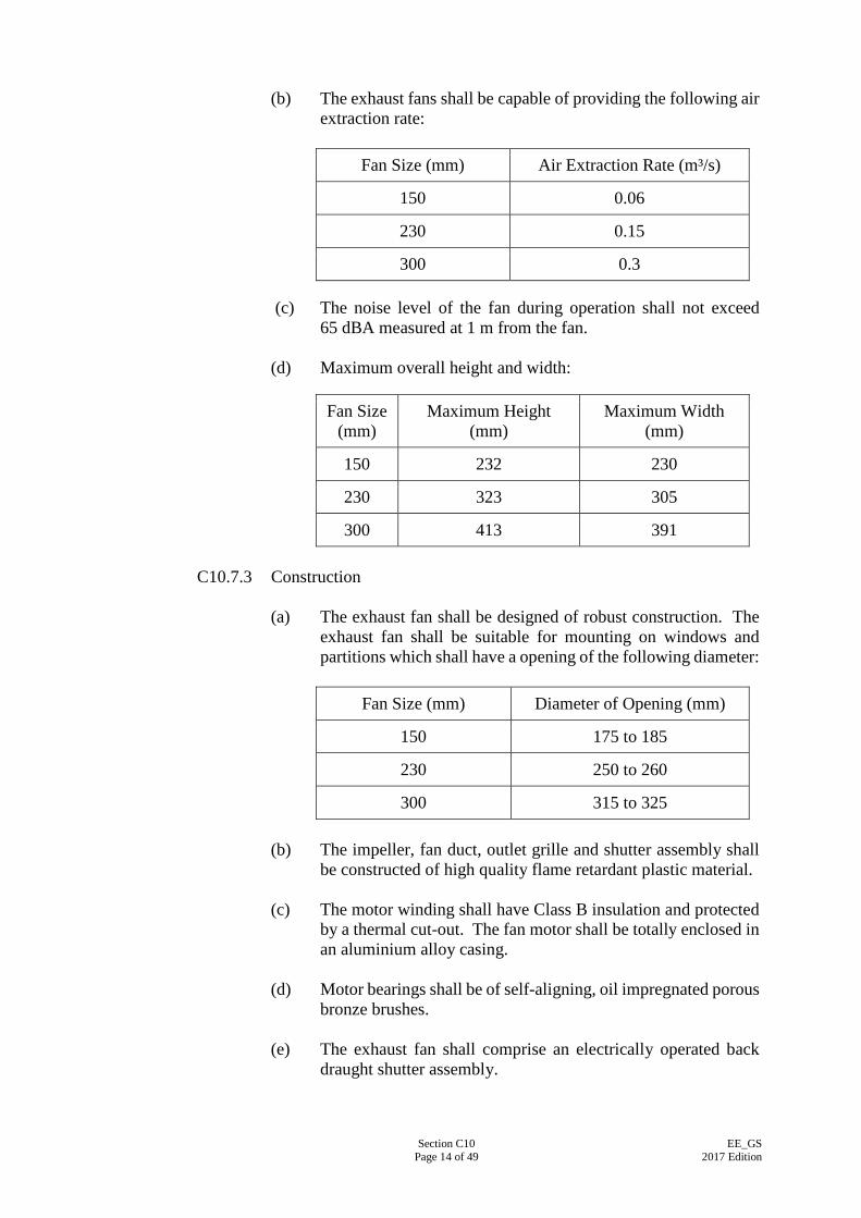
Section C10 Page 14 of 49
EE_GS 2017 Edition
(b) The exhaust fans shall be capable of providing the following air
extraction rate:
Fan Size (mm) Air Extraction Rate (m³/s)
150 0.06
230 0.15
300 0.3
(c) The noise level of the fan during operation shall not exceed 65 dBA measured at 1 m from the fan.
(d) Maximum overall height and width:
Fan Size (mm)
Maximum Height (mm)
Maximum Width (mm)
150 232 230
230 323 305
300 413 391
C10.7.3 Construction (a) The exhaust fan shall be designed of robust construction. The
exhaust fan shall be suitable for mounting on windows and partitions which shall have a opening of the following diameter:
Fan Size (mm) Diameter of Opening (mm)
150 175 to 185
230 250 to 260
300 315 to 325 (b) The impeller, fan duct, outlet grille and shutter assembly shall
be constructed of high quality flame retardant plastic material. (c) The motor winding shall have Class B insulation and protected
by a thermal cut-out. The fan motor shall be totally enclosed in an aluminium alloy casing.
(d) Motor bearings shall be of self-aligning, oil impregnated porous
bronze brushes. (e) The exhaust fan shall comprise an electrically operated back
draught shutter assembly.
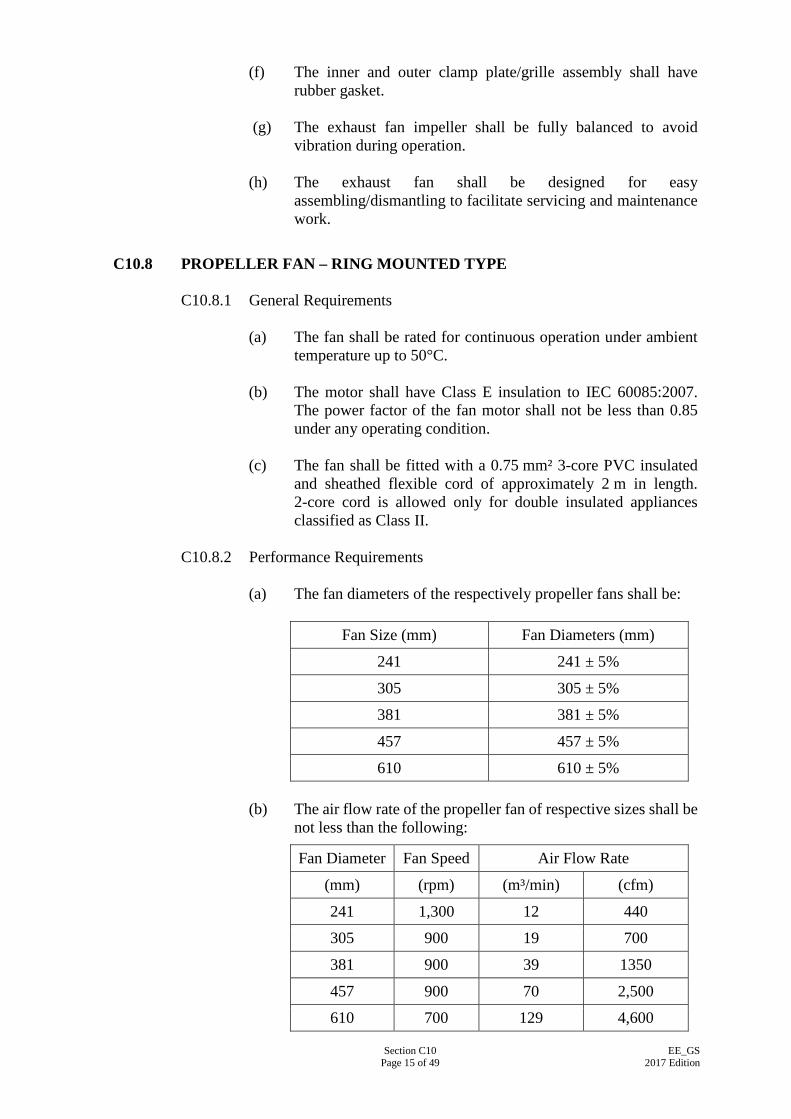
Section C10 Page 15 of 49
EE_GS 2017 Edition
(f) The inner and outer clamp plate/grille assembly shall have rubber gasket.
(g) The exhaust fan impeller shall be fully balanced to avoid
vibration during operation. (h) The exhaust fan shall be designed for easy
assembling/dismantling to facilitate servicing and maintenance work.
C10.8 PROPELLER FAN – RING MOUNTED TYPE
C10.8.1 General Requirements
(a) The fan shall be rated for continuous operation under ambient
temperature up to 50°C. (b) The motor shall have Class E insulation to IEC 60085:2007.
The power factor of the fan motor shall not be less than 0.85 under any operating condition.
(c) The fan shall be fitted with a 0.75 mm² 3-core PVC insulated
and sheathed flexible cord of approximately 2 m in length. 2-core cord is allowed only for double insulated appliances classified as Class II.
C10.8.2 Performance Requirements
(a) The fan diameters of the respectively propeller fans shall be:
Fan Size (mm) Fan Diameters (mm)
241 241 ± 5%
305 305 ± 5%
381 381 ± 5%
457 457 ± 5%
610 610 ± 5% (b) The air flow rate of the propeller fan of respective sizes shall be
not less than the following:
Fan Diameter Fan Speed Air Flow Rate
(mm) (rpm) (m³/min) (cfm)
241 1,300 12 440
305 900 19 700
381 900 39 1350
457 900 70 2,500
610 700 129 4,600
Section C10 Page 16 of 49
EE_GS 2017 Edition
(c) The sound pressure level emitted by the fan shall not exceed
65 dBA measured at 1 m from the fan outlet.
C10.8.3 Construction (a) The fan impeller shall be mounted on the same shaft as the
driving motor and constructed of heavy gauge pressed steel blades fitted to cast aluminium alloy hubs, fully balanced after assembly.
(b) The motor shall be of squirrel cage induction type, with
capacitor start and run, and of totally enclosed construction with dust seals.
(c) Ball or roller bearings shall be provided and shall be filled with
lithium based grease suitable for operating temperature between -30°C and 120°C.
(d) The fan and motor assembly shall have heavy duty and robust
steel mounting arms. (e) The mounting arms shall be fixed to the mounting ring through
a rubber or neoprene resilient cushion to reduce the transmission of vibration to the fixing surface.
(f) The mounting rings shall be constructed of steel pressing and
have sufficient flexibility to prevent fracture when fixed to slightly uneven surfaces.
(g) The fan shall be suitable for both vertical and horizontal
mounting. (h) The fan shall be supplied for air discharge away from the motor. (i) The fan assembly shall be protected with corrosion resistant
resin based paints. All bolts and nuts and washers shall be hot dip galvanised. The finishing coat shall be in grey colour unless otherwise specified.
(j) All exposed metal parts shall be effectively bonded together
and connected to a common earthing terminal. (k) If screws and nuts are fitted onto the fan blades for balancing
purpose, spring washer should be provided to avoid loosening. Other securing mechanism such as welding shall be subject to the approval of the Supervising Officer.
Section C10 Page 17 of 49
EE_GS 2017 Edition
C10.9 FUME CUPBOARD EXHAUST FAN
C10.9.1 General Requirements (a) The equipment shall be of axial flow design composed of
durable materials and quiet in operation. (b) Duct connector, cupboard adaptor, clamp ring, Jubilee clips
shall be provided. All of them shall be highly resistant to corrosive gases and chemical fumes emitted during chemical reactions as resulted from laboratory experiments and shall be capable of handling gases and fumes of from 0°C to 40°C.
C10.9.2 Performance Requirements
(a) The fan shall cover the range from 240 to 300 mm in nominal
diameter. (b) The revolution speed of the fan shall be not less than 2,700 rpm. (c) The air volume flow rate shall be not less than 0.35 m³/s in
static pressure of 100 N/m². (d) The noise level of the fan at all operating speeds shall not
exceed 58 dBA measured at 1 m from the fan.
C10.9.3 Construction (a) Motor
(i) The fan shall be driven by a totally enclosed but
externally cooled single phase induction motor of metric design to the latest edition of IEC 60034-1:2014.
(ii) Insulation shall be not lower than Class E as defined in
IEC 60085:2007. (iii) The motor shall be rated for continuous running at
ambient temperature of up to 40°C. (iv) The motor shall be protected by a sealing coat of
polyurethane compound or equivalent material.
(b) The impellers shall be moulded in phenolic resin or equivalent material.
(c) Circular fan casing shall be made from rigid PVC or galvanised
steel coated with epoxy resin or equivalent material. Ends of the casing shall be spigotted for attachment of duct and fume cupboard connectors respectively.
Section C10 Page 18 of 49
EE_GS 2017 Edition
(d) Terminal box (i) Terminal box shall be made of the same material as the
casing and shall be located outside air stream and affixed to the casing.
(ii) Terminal box shall be suitable for reception of a 2 m
long, 3-core 1.25 mm² flexible cable to BS EN50525-2-11:2011. The cable shall be fitted with the fan. 2-core cord is allowed only for double insulated appliances classified as Class II.
(iii) Duct/cupboard connectors and accessories shall be made
from corrosion resistant material such as neoprene, epoxy resin or other approved material.
(iv) The fan shall be suitable for mounting vertically,
horizontally or at an inclined angle. Normally, the duct/cupboard connectors will support the fan when fitted to the duct work. Extra supporting facilities in the form of two extended ribs shall be provided on the casing and shall be drilled for fixing supporting brackets.
C10.10 1 kW ELECTRIC FIRE, WALL MOUNTED TYPE
C10.10.1 General Requirements (a) The electric fire shall comply with IEC 60335-2-30:2009. (b) The electric fire shall be fitted with a 1.25 mm² 3-core PVC
insulated and sheathed flexible cord of approximately 1.5 m in length.
C10.10.2 Performance Requirements
The electric fire shall be fitted with one replaceable infra-red heating element of 1 kW rating.
C10.10.3 Construction
(a) The electric fire shall be of wall mounted type. (b) The electric fire shall be of all metal construction incorporating
an attractive chromium plated reflector which can be swiveled for directional adjustment of the reflected heat beam.
(c) A close mesh chromium plated fire guard shall be provided over
the entire length of the heating element and over the major
Section C10 Page 19 of 49
EE_GS 2017 Edition
portion of the reflector. The gap of the guard slots shall be not greater than 13 mm.
(d) The electric fire shall have adequate mechanical strength and stability to withstand rough handling as may be expected in normal use.
(e) The electric fire shall be fitted with a pull cord “ON/OFF”
switch.
C10.11 2 kW CONVECTOR FIRE
C10.11.1 General Requirements (a) The convector fire shall comply with IEC 60335-2-30:2009. (b) The convector fire shall be fitted with a 1.25 mm² 3-core PVC
insulated and sheathed flexible cord of approximately 3 m in length; and a suitably fused 13 A plug.
C10.11.2 Performance Requirements
The power rating shall range from 2 kW to 2.5 kW.
C10.11.3 Construction (a) The convector fire shall be of vertical floor-standing type. (b) The convector fire shall be of robust and all steel construction
with no sharp edges, non-marking feet if applicable and suitably finished and protected with corrosion and heat resistant paints of approved type.
(c) The convector fire shall have an on-off switch incorporating an
indicating lamp showing that power is available. (d) The convector fire shall have an adjustable thermostat for room
temperature control. (e) The convector fire shall be fitted with a close mesh chromium
plated front grille. The gap of the grille slots shall be not greater than 13 mm.
C10.12 2 kW OIL-FILLED ELECTRIC RADIATOR
C10.12.1 General Requirements (a) The radiator shall comply with IEC 60335-2-30:2009.
Section C10 Page 20 of 49
EE_GS 2017 Edition
(b) The radiator shall be fitted with a 1.25 mm² 3-core PVC insulated and sheathed flexible cord of approximately 3 m in length; and a suitably fused 13 A plug.
C10.12.2 Performance Requirements
The power rating shall range from 2 kW to 2.5 kW.
C10.12.3 Construction (a) The radiator shall be of vertical floor-standing type. (b) The casing of the radiator shall be constructed of sheet steel, or
equivalent. The casing shall be leak-proof and robust in construction and complete with castor wheels.
(c) The external of casing shall be finished with white or grey stove
enamel paints. (d) All fins shall be rounded and free from sharp edges. (e) The radiator shall have a selector switch providing at least 2
stages of heating. (f) The radiator shall have an on-off switch incorporating an
indicating lamp showing that power is available. (g) The radiator shall have an adjustable thermostat for room
temperature control. (h) The heating element shall be totally immersed in non
flammable oil.
C10.13 300 MM AND 1,200 MM SINGLE TUBULAR HEATER COMPLETE WITH WIRE GUARD
C10.13.1 General Requirements
(a) The design and the construction of the heater shall comply with
IEC 60335-1:2013 and IEC 60335-2-30:2009. (b) The heater shall be designed for use as wardrobe heater. (c) The heater shall be of robust construction, durable and
maintenance free under normal operating condition. (d) The hottest accessible part of the heater shall not exceed 80°C.
C10.13.2 Performance Requirements The maximum power rating of the heaters shall be:
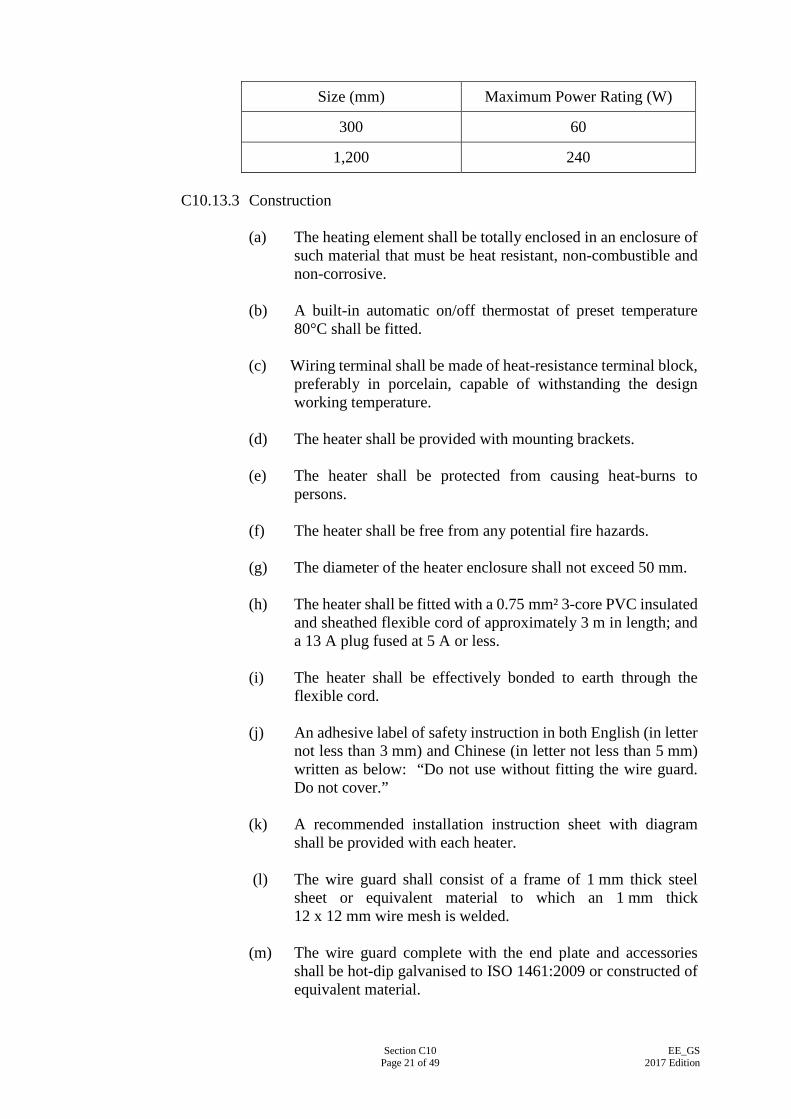
Section C10 Page 21 of 49
EE_GS 2017 Edition
Size (mm) Maximum Power Rating (W)
300 60
1,200 240 C10.13.3 Construction
(a) The heating element shall be totally enclosed in an enclosure of
such material that must be heat resistant, non-combustible and non-corrosive.
(b) A built-in automatic on/off thermostat of preset temperature
80°C shall be fitted. (c) Wiring terminal shall be made of heat-resistance terminal block,
preferably in porcelain, capable of withstanding the design working temperature.
(d) The heater shall be provided with mounting brackets. (e) The heater shall be protected from causing heat-burns to
persons. (f) The heater shall be free from any potential fire hazards. (g) The diameter of the heater enclosure shall not exceed 50 mm. (h) The heater shall be fitted with a 0.75 mm² 3-core PVC insulated
and sheathed flexible cord of approximately 3 m in length; and a 13 A plug fused at 5 A or less.
(i) The heater shall be effectively bonded to earth through the
flexible cord. (j) An adhesive label of safety instruction in both English (in letter
not less than 3 mm) and Chinese (in letter not less than 5 mm) written as below: “Do not use without fitting the wire guard. Do not cover.”
(k) A recommended installation instruction sheet with diagram
shall be provided with each heater. (l) The wire guard shall consist of a frame of 1 mm thick steel
sheet or equivalent material to which an 1 mm thick 12 x 12 mm wire mesh is welded.
(m) The wire guard complete with the end plate and accessories
shall be hot-dip galvanised to ISO 1461:2009 or constructed of equivalent material.
Section C10 Page 22 of 49
EE_GS 2017 Edition
(n) The clearance between the heater and the wire guard shall be not less than 20 mm.
C10.14 10-Litre OPEN-OUTLET TYPE, ELECTRIC SINK WATER HEATER
C10.14.1 General Requirements (a) The hot water capacity shall not be less than 10 litres. (b) The sink water heater shall be suitable for installing above the
water sink. (c) The sink water heater shall be of wall-mounted type. (d) The sink water heater shall comply with IEC 60335-2-21:2012.
C10.14.2 Performance Requirements (a) The sink water heater shall be capable of maintaining water
temperature in the container between 55°C and 78°C irrespective of the water inlet temperature and ambient air conditions.
(b) The water container shall be suitable for connection to a mains
water supply having a pressure of not less than 205 kPa. A pressure test certificate shall be provided for each sink water heater quoting the manufacturer’s serial number and confirming that a pressure test to manufacturer’s standard or 50 kPa, whichever is greater, has been successfully applied.
(c) The nominal power rating of the sink water heater shall be
3 kW.
C10.14.3 Construction (a) The sink water heater shall be provided with an adjustable
thermostat with ample current rating to maintain water temperature from 55°C to 78°C.
(b) The sink water heater shall be provided with a non-resettable
thermal cut-out to protect the water temperature inside the container from exceeding 90°C in order to provide additional safety protection.
(c) Earthing terminal shall be provided. (d) The inner hot water container shall be suitable for local
installation. (e) The construction material of the inner hot water container shall
be designed and chosen by the combined merits on
Section C10 Page 23 of 49
EE_GS 2017 Edition
expandability, thermal conductivity, susceptibility to surface fouling, reaction to water acidity and alkalinity on boiler applications, such as tinned copper, or equivalent.
(f) The outer casing shall be drip-proof and constructed from
heavy gauge sheet steel properly treated to prevent corrosion or equivalent material.
(g) The outer casing shall be in white colour. (h) The thermal insulating material shall be of non-combustible and
non-CFC type. (i) A swivel spout at outlet of 300 mm approx. in radius shall be
provided. (j) The sink water heater shall be provided with a permanent
warning label in English and Chinese characters as follows: “The outlet from the water heater must not be blocked or connected to any form of fitting with an isolating valve”.
(k) The following pipe fittings shall be provided at inlet side:
(i) A water control valve (ii) A non-return valve (iii) A water strainer
C10.15 90-Litre AND 135-Litre THERMAL STORAGE ELECTRIC WATER HEATER
C10.15.1 General Requirements
(a) The water heater shall comply with the relevant requirements of
Electrical Products (Safety) Regulation, (Cap.406G), Laws of Hong Kong.
(b) The water heater shall comply with the relevant requirements of
Waterworks Ordinance, (Cap.102), Laws of Hong Kong. (c) The water heater shall comply with Code of Practice for the
Electricity (Wiring) Regulations issued by the EMSD . (d) The water heater shall comply with the relevant requirements of
Boilers and Pressure Vessels Ordinance, (Cap.56), Laws of Hong Kong.
(e) The power rating of the product shall range from 2.5 kW to
3 kW.

Section C10 Page 24 of 49
EE_GS 2017 Edition
(f) The water heater shall comply with the latest edition of the following standards: (i) For unvented thermal storage type electric water heater
IEC 60335-2-21:2012 Household and similar electrical appliances – Safety – Part 2-21 : Particular requirements for storage water heaters; and BS EN 12897:2006 Specification for unvented hot water storage units and packages;
(ii) For thermal cut out
BS EN 60730-2-15:2010 Specification for electrical controls for household and similar general purposes; and
(iii) For temperature and pressure relief valve
BS 6283-2:1991 Safety and control devices for use in hot water systems. Specification for temperature relief valves for pressures from 1 bar to 10 bar.
C10.15.2 Performance Requirements
(a) The hot water cylinder shall be suitable for a working pressure
of 10 bar or below. A test certificate shall be provided for each water heater quoting the manufacturer’s serial number and confirming that a pressure test to manufacturer’s standard or 1.5 times the working pressure, whichever is greater, has been successfully applied.
(b) The hot water storage capacity shall be:
Size of water heater (litres)
Hot Water Storage Capacity (litres)
90 From 90 litres to 100 litres
135 From 135 litres to 155 litres (c) The water heater shall have obtained a Grade 1 Energy Label
under the Energy Efficiency Labelling Scheme of Electrical and Mechanical Services Department.
C10.15.3 Specific Safety Requirements
(a) The safety standard to which the product conforms and the
storage capacity in litres (l) should be clearly and permanently marked on the body of the product in additional to the marking requirements stipulated in the essential safety requirements for electrical products in Electrical Products (Safety) Regulation, (Cap. 406G), Laws of Hong Kong.
Section C10 Page 25 of 49
EE_GS 2017 Edition
(b) Manufacturer’s installation instructions including
recommendations and warnings to users and installers, etc., should also be provided and clearly marked.
(c) The construction material of the hot water cylinder shall be
corrosion resistance, such as copper, stainless steel or other equivalent material. The cylinder shall be capable of withstanding 1.5 times the working pressure.
(d) The water heater shall be fitted with a thermostat (with a
maximum setting temperature of 80°C) to control the heating of the stored water.
(e) The water heater shall be fitted with a thermal cut-out
(complying with BS EN 60730-2-15:2010 and with a temperature setting of 85°C) to cut off the supply of electricity if the stored water is heated above the temperature setting of the thermostat and before the operation of the temperature and pressure relief valve is initiated. The thermal cut-out should be connected in series with the thermostat and should be reset manually after dismantling of the enclosure of the product.
(f) The water heater shall be fitted with
EITHER (i) a non-resettable temperature relief valve (complying
with BS 6283-2:1991), having a setting of 90°C, and complete with manual test easing gear; AND a pressure relief valve (complying with BS 6283-2:1991), having a set pressure of not greater than the maximum design pressure of the water heater or 10 bar, and complete with manual test easing gear;
OR (ii) a non-resettable temperature and pressure relief valve
complying with the requirements of BS 6283-2:1991, having a set temperature of 90°C and a set pressure of the water heater or 10 bar, and complete with manual test easing gear.
C10.15.4 Construction
(a) The hot water cylinder shall be suitable for local installation. (b) The water heater shall be provided with an anti-vacuum valve
complying with BS EN 13959:2004 or other relevant Parts to prevent heated water from being siphoned back to supply pipe during water shortage period.
Section C10 Page 26 of 49
EE_GS 2017 Edition
(c) A draining device shall be provided to discharge water and shall be arranged so as to be clear of all the electrical connections and terminals.
(d) The outer casing shall be drip-proof and constructed from
heavy gauge sheet steel properly treated to prevent corrosion or equivalent material.
(e) The outer casing shall be in white colour. (f) The thermal insulating material shall be of non-combustible and
non-CFC type. (g) The water heater shall be suitable for vertical floor or wall
mounting. It shall be completed with water inlet and outlet suitable for connection to standard water pipe. The inlet and outlet pipes shall be clearly marked on the product and the British Standard Pipe (BSP) sizes shall be clearly stated in installation instructions.
(h) Material used in the connection to the hot water cylinder shall
be of corrosion resistant type, especially on the water side. (i) The electric terminal box with cover and suitable for fitting with
waterproof metallic flexible conduit shall be provided.
C10.16 ELECTRIC TEA URN
C10.16.1 General Requirements (a) The tea urn shall be suitable for providing boiling water for tea. (b) The tea urn shall comply with the standard
IEC 60335-2-75:2015. (c) All electrical components shall comply with the relevant IEC
Standards, or of fully equivalent quality and capacity.
C10.16.2 Performance Requirements (a) The capacity of the tea urn shall be 14-20 litres. (b) The power rating shall range from 2.5 kW to 2.8 kW.
C10.16.3 Construction
(a) The water container of the tea urn shall be constructed from
stainless sheet steel or material of equivalent quality. (b) The tea urn shall be of circular table standing model complete
with a full size detachable top cover and two heat-insulated handles.
Section C10 Page 27 of 49
EE_GS 2017 Edition
(c) The tea urn shall be provided with either a simmerstat
temperature control or 3 heat rotary switch. (d) The tea urn shall be provided with a self-resettable thermal
cut-out against failure due to boiling dry. (e) The tea urn shall be provided with rapid draw off tap with
heat-insulated handle. (f) The tea urn shall be fitted with a flexible power supply cable
and a suitably fused 13 A plug complying with the Electrical Products (Safety) Regulation, (Cap.406G), Laws of Hong Kong. The minimum length of the flexible cable shall be 1.5 m.
(g) Internal wiring of the tea urn shall be suitable for high
temperature operation.
C10.17 ELECTRIC KETTLE 3.5-4.5 Litres
C10.17.1 General Requirements (a) The kettle shall comply with the latest edition of
IEC 60335-2-15:2012. (b) The kettle shall be fitted with a 0.75 mm² 3-core PVC insulated
and sheathed flexible cord of approximately 1.5 m in length complete with an “appliance connector” and a suitably fused 13 A plug.
C10.17.2 Performance Requirements
(a) The water capacity of the kettle shall be ranged from 3.5 to 4.5
litres. (b) The electrical power capacity of the kettle shall range from
2 kW to 2.6 kW.
C10.17.3 Construction (a) The kettle shall be designed for providing boiling water for
drinking. (b) The construction material shall be made from heavy gauge
chromium plated copper; or high quality heavy gauge polished aluminium; or stainless steel.
(c) The kettle shall be fitted with a safety cut-out to keep the kettle
from boiling dry.
Section C10 Page 28 of 49
EE_GS 2017 Edition
C10.18 MAINS-SUPPLY DRINKING WATER DISPENSER FOR “COLD” WATER C10.18.1 General Requirements
(a) The water dispenser shall be suitable for local installation and
must comply with the statutory requirements of the Waterworks Regulation 24, (Cap.102A) , Laws of Hong Kong.
(b) The water dispenser shall comply with the Telecommunication
(Control of Interference) Regulations, (Cap.106B), Laws of Hong Kong.
(c) The water dispenser shall comply with the latest edition of
IEC 60335-2-24:2012. C10.18.2 Performance Requirements
The water dispenser shall provide not less than 45.5 litres per hour of chilled drinking water at a temperature of between 10°C and 13°C from a water inlet temperature of 27°C under ambient air conditions of 32°C and 85% relative humidity.
C10.18.3 Construction
(a) The water dispenser shall be designed to receive water supply from the standard premises water mains and shall be provided with a single ½ inch BSP male threaded connection located at the back and protruding by not more than 25 mm.
(b) The water dispenser shall be designed for heavy duty
application. (c) The water dispenser shall be provided with an automatic
thermostat to control the “cold” water delivery at the above specified temperatures, irrespective of water inlet temperature and ambient air conditions, within the range specified above.
(d) The cabinet shall be constructed, of brushed finished stainless
steel, of minimum 1 mm thickness to ensure complete rigidity and to resist “in-use” denting, or equivalent.
(e) The drip pan below the tap(s) shall be of a suitable grade of
stainless steel to ensure that no rusting will occur during the expected service life of the unit. It shall be connected to a drain pipe terminating at the back of the unit and shall have a 1” BSP male thread for connection to the premises drainage system.
(f) The cold water reservoir shall be manufactured from a suitable
grade of stainless steel or copper, fitted with an external copper pipe refrigerant coil and foamed in place with high efficiency insulation of appropriate thickness.
Section C10 Page 29 of 49
EE_GS 2017 Edition
(g) The base plate shall be at least 20 mm above the ground level. (h) The faucet(s) shall be manufactured from polypropylene or
chromium plated steel, and either the push-button or swivel type, self-closing, easy to operate and suitably positioned for filling cups, glasses, etc.
(i) The refrigeration system shall be of the hermetically sealed type,
suitably rated to meet the above specified duty. The condenser shall be air cooled with either natural, or, forced circulation.
(j) The refrigerant used shall be non-toxic, non-explosive,
odourless and non-CFC type. (k) The water dispenser shall be fitted with the following devices:
(i) A “power ON” indicator light; and (ii) An indicator light for the refrigeration unit to indicate its
operation.
(l) The water dispenser shall be fitted with a 3-core PVC insulated and sheathed flexible cable conforming to BS EN50525-2-11:2011 or equivalent standards, and complete with a suitably fused 13 A plug conforming to the Electrical Products (Safety) Regulation, (Cap.406G), Laws of Hong Kong. The supply cable shall be approx. 2 m long.
C10.19 DOMESTIC ELECTRIC COOKER (TABLE MODEL)
C10.19.1 General Requirements (a) The cooker shall be designed for table top use. (b) The cooker shall have two radiant rings, grill and oven. (c) The cooker shall comply with IEC 60335-2-6:2014. (d) The overall dimensions of the cooker shall be 390 mm (height)
x 470 mm (width) x 420 mm (depth) approximately.
C10.19.2 Performance Requirements The total electrical loading shall be made up with the components having the ratings as below: (a) Radiant rings (total) : not less than 2 kW; (b) Grill : not less than 1 kW; and
Section C10 Page 30 of 49
EE_GS 2017 Edition
(c) Oven : not less than 1 kW.
C10.19.3 Construction (a) The diameter of the two radiant rings shall be as follows:
(i) one radiant ring of diameter 145 mm approximately; and (ii) one radiant ring of diameter 170 mm approximately.
(b) The dimensions of the grille shall be 310 mm (width) x 155 mm (depth) approximately.
(c) The dimensions of the oven shall be 200 mm (height) x 380 mm
(width) x 290 mm (depth) approximately and the volume of the oven shall be 20 litres approximately.
(d) All radiant rings, grill, and oven shall be simmerstat controlled
with power-on and oven indicator lamps. (e) All screws, nuts and bolts shall be rust-proof or manufactured
from non-ferrous metal. (f) The main terminals shall be mounted on the base at the back and
accessible for mains connections by removing the exterior back panel.
(g) The cooker shall have adequate mechanical strength and be so
constructed as to withstand such rough usage as may be expected in normal use.
(h) Radiant rings and oven shall be easily removable to facilitate
cleaning. (i) The cooker shall be finished in white or cream vitreous enamel
paint. (j) Internal wiring of the cooker shall be suitable for high
temperature operation. (k) The cooker shall be fitted with a 3-core, 2 m long
approximately power supply cable conformed to BS EN50525-2-11:2011; and controlled by a 20 A D.P. switch.
(l) The cooker shall be fitted with overload protection switch.
C10.20 DOMESTIC ELECTRIC COOKER (FOUR RADIANT PLATES TYPE)
C10.20.1 General Requirements The cooker shall comply IEC 60335-2-6:2014.
Section C10 Page 31 of 49
EE_GS 2017 Edition
C10.20.2 Performance Requirements
The total electrical loading shall be made up with the components having the ratings as below: (a) Radiant Plates (total) : not less than 5.8 kW; (b) Grilling Compartment : not less than 2.5 kW; and (c) Oven : not less than 2.5 kW.
C10.20.3 Construction (a) The overall dimensions shall be:
(i) Total Height : approximately 1,300 mm; (ii) Height to Hob : approximately 900 mm; (iii) Width : approximately 550 mm; and (iv) Depth : approximately 600 mm.
(b) The capacity shall be: (i) Grilling Compartment
Grilling Usable Area : not less than 850 cm²; and (ii) Oven Compartment
Oven Volume : not less than 55 litres.
(c) The cooker shall consist of four radiant plates on the hob, an oven compartment and an individual grille compartment.
(d) The cooker shall be constructed basically from mild steel or
material of equivalent strength and quality, and shall be finished externally white with vitreous enamel paint.
(e) The oven components shall be removable to facilitate cleaning.
All screws, nuts and bolts in the oven compartment and grilling compartment shall be rust-proof or manufactured from non-ferrous metal.
(f) Each radiant plate and the grilling compartment shall be
equipped with an adjustable control to obtain variable heat output.
(g) The radiant plate shall not be of the sealed plate type.
Section C10 Page 32 of 49
EE_GS 2017 Edition
(h) The hob could be lifted up for replacement of the radiant plates and cleaning purpose. When the hob is raised, a supporting device shall be provided to prevent the falling down of the hob.
(i) The temperature inside the oven compartment shall be
thermostatically controlled with adjusting knobs on the front panel.
(j) The heater of the oven shall be suitably guarded off so as to
protect the user from heat burn. (k) The oven door shall be of glass pull out type hinged at the
bottom. (l) The oven shall be provided with an interior light. (m) Internal wiring of the cooker shall be suitable for high
temperature operation. (n) The supply cable of the cooker shall conform to BS
EN50525-2-11:2011 or other equivalent standards and the cooker shall be controlled by a 60 A D.P. cooker control unit.
C10.21 ELECTRIC HOT PLATE
C10.21.1 General Requirements The hot plate shall comply with IEC 60335-2-6:2014.
C10.21.2 Performance Requirements The capacity shall range from 2 kW to 2.6 kW.
C10.21.3 Construction (a) The hot plate shall be designed for use on the table top. (b) The heating element shall be metal sheathed. (c) The diameter of the heating surface shall range from 180 mm to
200 mm approximately. (d) The top plate shall be constructed of steel plate of minimum
thickness 3 mm, or equivalent material. (e) The top plate shall be protected with heat resisting coating to
prevent thermal oxidation of the steel plate during operation. (f) The level of top plate shall range from 120 to 130 mm above the
table top.
Section C10 Page 33 of 49
EE_GS 2017 Edition
(g) The casing/stand of the hot plate shall be constructed of chrome plated sheet or stoved with heat resisting enamel.
(h) The hot plate shall have integral power and temperature control
switch which shall have at least 3 temperature settings. (i) All bare metal conductors except the top plate shall properly be
heat insulated. (j) Internal wiring of the hot plate shall be suitable for high
temperature operation. (k) The hot plate shall be provided with a 3-core flexible power
supply cable of approximately 1.5 m in length complete with a suitably fused 13 A plug.
C10.22 10-PERSONS AND 15-PERSONS ELECTRIC RICE COOKER
C10.22.1 General Requirements (a) The rice cooker shall comply with IEC-60335-2-15:2012. (b) The rice cooker shall be provided with a detachable 0.75 mm²
3-core circular cotton braided, rubber sheathed or PVC insulated and sheathed flexible cord of approximately 1 m in length and complete with an “appliance connector” and a suitably fused 13 A plug.
C10.22.2 Performance Requirements
The capacities of the rice cookers shall be:
Size (Persons) Capacity (Persons)
10 From 7 to 10 persons
15 From 11 to 16 persons
C10.22.3 Construction (a) The rice cooker shall be finished with heat resisting paint in
white or a manufacturer’s standard colour approved by the Supervising Officer.
(b) The rice cooker shall be fitted with automatic heat preservation
mechanism and overheating protection. (c) Internal wiring of the rice cooker shall be suitable for high
temperature operation.
Section C10 Page 34 of 49
EE_GS 2017 Edition
C10.23 2 kW ELECTRIC TOASTER
C10.23.1 General Requirements The toaster shall comply with IEC 60335-2-9:2012.
C10.23.2 Performance Requirements The total power rating of the heating elements shall not exceed 2 kW.
C10.23.3 Construction (a) The toaster shall have two separate chambers for toasting two
slices of bread simultaneously. (b) The toaster shall have an automatic pop-up mechanism that
shall be controlled by a damper to eliminate excessive shock and vibration during operation of the mechanism.
(c) A selector switch shall be provided for selection of the degree
of toasting. (d) The casing shall be constructed of stainless steel or chromium
plated steel. (e) The toaster shall be designed for easy operation and
maintenance. (f) The supply cable shall conform to BS EN50525-2-11:2011 and
complete with a suitably fused 13 A plug conforming to the Electrical Products (Safety) Regulation, (Cap.406G), Laws of Hong Kong. The length of the supply cable shall be not less than 1.5 m.
C10.24 ELECTRIC HAND/FACE DRYER
C10.24.1 General Requirements (a) The hand/face dryer shall comply with IEC 60335-2-23:2012. (b) The hand/face dryer shall be designed of wall-mounting type. (c) The hand/face dryer shall be provided with a detachable
1.25 mm² 3-core PVC insulated and sheathed flexible cord of approximately 1 m in length.
C10.24.2 Performance Requirements
(a) The front cover shall withstand a static force of not less than
111 N for 1 minute and an impact of not less than 6.8 J for 1 minute.
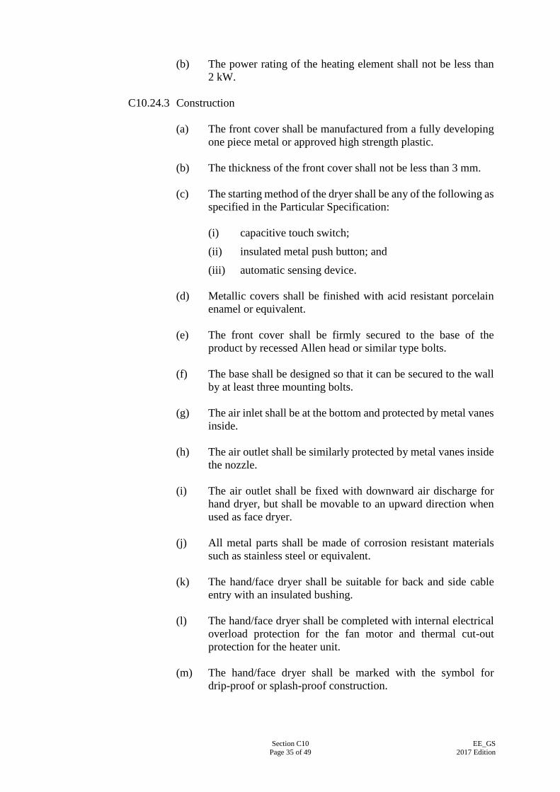
Section C10 Page 35 of 49
EE_GS 2017 Edition
(b) The power rating of the heating element shall not be less than
2 kW.
C10.24.3 Construction (a) The front cover shall be manufactured from a fully developing
one piece metal or approved high strength plastic. (b) The thickness of the front cover shall not be less than 3 mm. (c) The starting method of the dryer shall be any of the following as
specified in the Particular Specification:
(i) capacitive touch switch;
(ii) insulated metal push button; and
(iii) automatic sensing device. (d) Metallic covers shall be finished with acid resistant porcelain
enamel or equivalent. (e) The front cover shall be firmly secured to the base of the
product by recessed Allen head or similar type bolts. (f) The base shall be designed so that it can be secured to the wall
by at least three mounting bolts. (g) The air inlet shall be at the bottom and protected by metal vanes
inside. (h) The air outlet shall be similarly protected by metal vanes inside
the nozzle. (i) The air outlet shall be fixed with downward air discharge for
hand dryer, but shall be movable to an upward direction when used as face dryer.
(j) All metal parts shall be made of corrosion resistant materials
such as stainless steel or equivalent. (k) The hand/face dryer shall be suitable for back and side cable
entry with an insulated bushing. (l) The hand/face dryer shall be completed with internal electrical
overload protection for the fan motor and thermal cut-out protection for the heater unit.
(m) The hand/face dryer shall be marked with the symbol for
drip-proof or splash-proof construction.

Section C10 Page 36 of 49
EE_GS 2017 Edition
C10.25 (NOT USED)
C10.26 WALL CLOCK BATTERY-OPERATED
C10.26.1 General Requirements The clock shall be accompanied with the necessary battery adequate for operating the clock for at least 1 month.
C10.26.2 Performance Requirements (a) The clock shall be tropicalised and dust-proof. (b) The accuracy of timekeeping shall not exceed ±20 sec/month at
room temperature (25°C).
C10.26.3 Construction (a) The clock-face shall either be round or square in shape as
specified in the Particular Specification. (b) For round clock-face clock, the nominal clock-face diameter
shall range between 300 mm and 350 mm. (c) For square clock-face clock, the nominal clock-face side length
shall range between 300 mm and 350 mm. (d) The clock shall be flush mounted design on the wall and is to be
free of any projections on the rear surface. (e) The clock dial shall be white with large Arabic Numerals in
black and graduated in minutes. Alternative colour and design shall be subject to the approval of the Supervising Officer.
(f) The hour, minute and second full sweep hands shall be of
distinct colour. (g) The clock shall be completed with a clear glass or plastic front
cover. (h) The voltage rating of the battery powering the product shall not
exceed 1.5 V.
C10.27 ELECTRIC DRY IRON
C10.27.1 General Requirements (a) The dry iron shall be designed for household and domestic
application.
Section C10 Page 37 of 49
EE_GS 2017 Edition
(b) The dry iron shall comply with IEC 60335-2-3:2015. (c) The dry iron shall have adequate mechanical strength and
stability to withstand rough handling as may be expected in normal use.
(d) The dry iron shall be fitted with a 1.25 mm² 3-core PVC
insulated and sheathed flexible cord of approximately 2 m in length and a suitably fused 13 A plug.
C10.27.2 Performance Requirements
The rated input power of the dry iron shall be 1,000 W.
C10.27.3 Construction (a) The dry iron shall have an adjustable, self-resetting thermostat
control complete with indication lamp for power ON/OFF indication.
(b) The power cord shall be connected to the iron body in such a
manner that no part of the power cord or any accessories associated thereto shall be in contact with the hand of the operator during the normal ironing operation.
(c) The non-stick coated plate of the dry iron shall be constructed
of chromium plated or heat resistant aluminium alloy. (d) The dry iron shall have the appropriate degree of protection
against moisture.
C10.28 VACUUM CLEANER
C10.28.1 General Requirements (a) The vacuum cleaner shall comply with IEC 60335-2-2:2012. (b) The vacuum cleaner shall be suppressed against radio
interference in compliance with the Telecommunication (Control of Interference) Regulations, (Cap.106B), Laws of Hong Kong.
(c) The vacuum cleaner shall be designed of domestic type and for
dry load. (d) The vacuum cleaner shall be fitted with a 1.25 mm² 3-core PVC
insulated and sheathed flexible cord of approximately 5 m in length; and a suitably fused 13 A plug.
Section C10 Page 38 of 49
EE_GS 2017 Edition
C10.28.2 Performance Requirements (a) The minimum dust capacity shall be 3.4 litres. (b) The suction capacity shall be not less than 13.7 kPa. (c) The minimum air flow rate shall be 1.8 m³/min. (d) The operating noise level shall not exceed 80 dBA measured at
one (1) m from the vacuum cleaner under a background noise level of 55 dBA.
C10.28.3 Construction
(a) The vacuum cleaner shall be a double insulated product
(Class II appliance) and shall have the symbol for Class II construction marked on its body.
(b) The following accessories shall be supplied with the vacuum
cleaner as standard fittings: (i) Joint pipe; (ii) Flexible hose; (iii) Curved joint pipe; (iv) Extension pipes; (v) Combination rug and floor tool; (vi) Crevice nozzle; (vii) Dusting brush; and (viii) Fabric nozzle.
C10.29 FLOOR POLISHER
C10.29.1 General Requirements (a) The floor polisher shall comply with IEC 60335-2-40:2013. (b) The floor polisher shall be suppressed against radio interference
in compliance with the Telecommunication (Control of Interference) Regulations, (Cap.106B), Laws of Hong Kong.
(c) The floor polisher shall be fitted with a 1.25 mm² 3-core PVC
insulated and sheathed flexible cord of approximately 6 m in length; and a suitably fused 13 A plug.

Section C10 Page 39 of 49
EE_GS 2017 Edition
C10.29.2 Performance Requirements (a) The power rating shall not be less than 400 watts. (b) The dust bag volume shall not be less than 2.7 litres.
C10.29.3 Construction (a) The floor polisher shall be a double insulated product (Class II
appliance) and shall have the symbol for Class II construction marked on its body.
(b) The floor polisher shall be of the suction type with
interchangeable 3 sets of brush of three pieces each, comprising 3 hard texture brushes, 3 soft brushes and 3 felt pads, suitable for household and similar purposes.
C10.30 7-Litres AND 9-Litres DEHUMIDIFIER
C10.30.1 General Requirements (a) The dehumidifier shall comply with IEC 60335-2-40:2013. (b) The dehumidifier shall be fitted with a 1.25 mm² 3-core PVC
insulated and sheathed flexible cord of approximately 2 m in length; and a suitably fused 13 A plug.
C10.30.2 Performance Requirements
(a) The moisture removal capacity, when measured under the
operating conditions at 27°C, 60% R.H. shall be as follows:
Size (litres) Minimum Moisture Removal Capacity
7 7 litres per 24 hours
9 9 litres per 24 hours (b) The power factor of the dehumidifier shall be not less than 0.85. (c) The noise level generated whilst in operation shall not exceed
60 dBA measured at 1.5 m from the product under a background noise level of not exceeding 50 dBA.
(d) The dehumidifier shall have obtained a Grade 1 Energy Label
under the Energy Efficiency Labelling Scheme of Electrical and Mechanical Services Department.
C10.30.3 Construction
No “Controlled Refrigerant”, as defined under the Ozone Layer
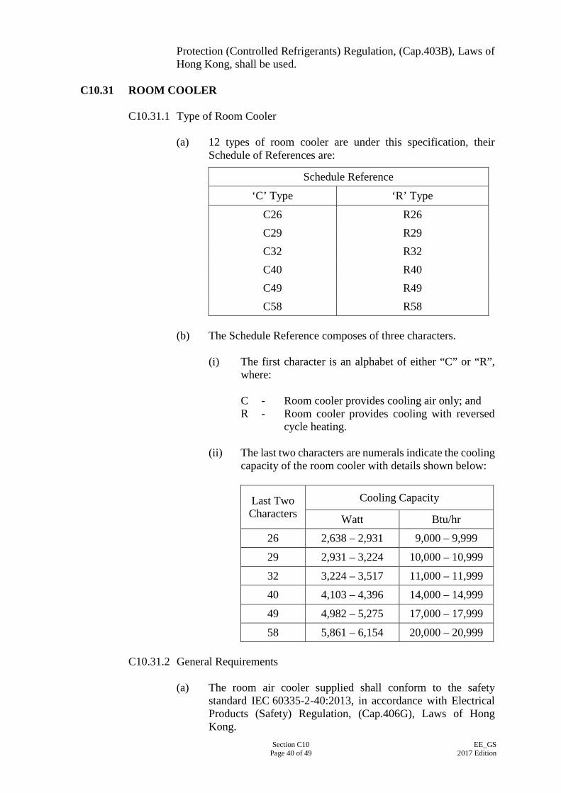
Section C10 Page 40 of 49
EE_GS 2017 Edition
Protection (Controlled Refrigerants) Regulation, (Cap.403B), Laws of Hong Kong, shall be used.
C10.31 ROOM COOLER
C10.31.1 Type of Room Cooler (a) 12 types of room cooler are under this specification, their
Schedule of References are:
Schedule Reference
‘C’ Type ‘R’ Type
C26 R26 C29 R29 C32 R32 C40 R40 C49 R49 C58 R58
(b) The Schedule Reference composes of three characters.
(i) The first character is an alphabet of either “C” or “R”, where: C - Room cooler provides cooling air only; and R - Room cooler provides cooling with reversed cycle heating.
(ii) The last two characters are numerals indicate the cooling
capacity of the room cooler with details shown below:
Last Two Characters
Cooling Capacity
Watt Btu/hr
26 2,638 – 2,931 9,000 – 9,999
29 2,931 – 3,224 10,000 – 10,999
32 3,224 – 3,517 11,000 – 11,999
40 4,103 – 4,396 14,000 – 14,999
49 4,982 – 5,275 17,000 – 17,999
58 5,861 – 6,154 20,000 – 20,999
C10.31.2 General Requirements (a) The room air cooler supplied shall conform to the safety
standard IEC 60335-2-40:2013, in accordance with Electrical Products (Safety) Regulation, (Cap.406G), Laws of Hong Kong.
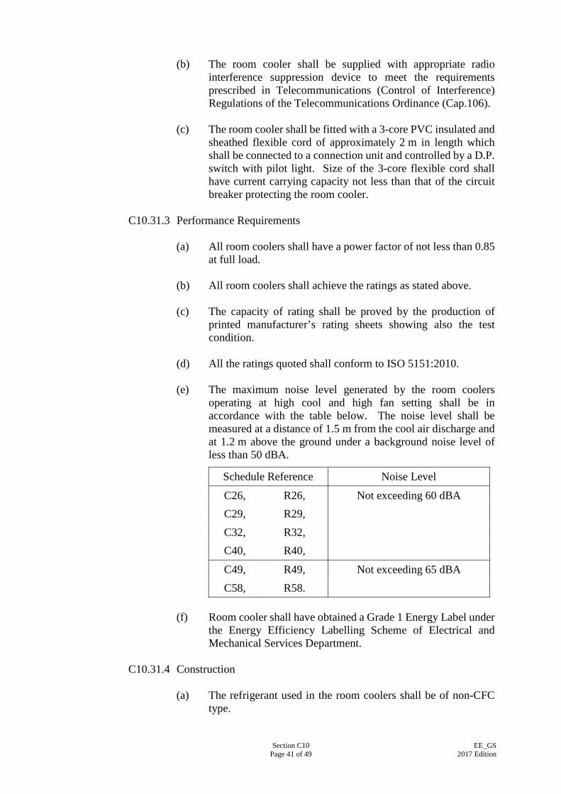
Section C10 Page 41 of 49
EE_GS 2017 Edition
(b) The room cooler shall be supplied with appropriate radio
interference suppression device to meet the requirements prescribed in Telecommunications (Control of Interference) Regulations of the Telecommunications Ordinance (Cap.106).
(c) The room cooler shall be fitted with a 3-core PVC insulated and
sheathed flexible cord of approximately 2 m in length which shall be connected to a connection unit and controlled by a D.P. switch with pilot light. Size of the 3-core flexible cord shall have current carrying capacity not less than that of the circuit breaker protecting the room cooler.
C10.31.3 Performance Requirements
(a) All room coolers shall have a power factor of not less than 0.85
at full load. (b) All room coolers shall achieve the ratings as stated above. (c) The capacity of rating shall be proved by the production of
printed manufacturer’s rating sheets showing also the test condition.
(d) All the ratings quoted shall conform to ISO 5151:2010. (e) The maximum noise level generated by the room coolers
operating at high cool and high fan setting shall be in accordance with the table below. The noise level shall be measured at a distance of 1.5 m from the cool air discharge and at 1.2 m above the ground under a background noise level of less than 50 dBA.
Schedule Reference Noise Level
C26, R26, Not exceeding 60 dBA C29, R29, C32, R32, C40, R40,
C49, R49, Not exceeding 65 dBA C58, R58.
(f) Room cooler shall have obtained a Grade 1 Energy Label under
the Energy Efficiency Labelling Scheme of Electrical and Mechanical Services Department.
C10.31.4 Construction
(a) The refrigerant used in the room coolers shall be of non-CFC
type.
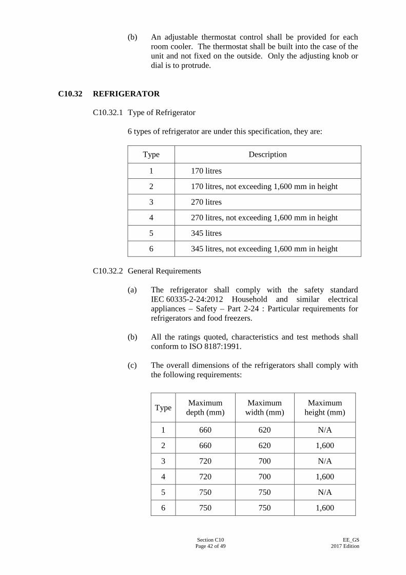
Section C10 Page 42 of 49
EE_GS 2017 Edition
(b) An adjustable thermostat control shall be provided for each room cooler. The thermostat shall be built into the case of the unit and not fixed on the outside. Only the adjusting knob or dial is to protrude.
C10.32 REFRIGERATOR
C10.32.1 Type of Refrigerator 6 types of refrigerator are under this specification, they are:
Type Description
1 170 litres
2 170 litres, not exceeding 1,600 mm in height
3 270 litres
4 270 litres, not exceeding 1,600 mm in height
5 345 litres
6 345 litres, not exceeding 1,600 mm in height
C10.32.2 General Requirements (a) The refrigerator shall comply with the safety standard
IEC 60335-2-24:2012 Household and similar electrical appliances – Safety – Part 2-24 : Particular requirements for refrigerators and food freezers.
(b) All the ratings quoted, characteristics and test methods shall
conform to ISO 8187:1991. (c) The overall dimensions of the refrigerators shall comply with
the following requirements:
Type Maximum depth (mm)
Maximum width (mm)
Maximum height (mm)
1 660 620 N/A
2 660 620 1,600
3 720 700 N/A
4 720 700 1,600
5 750 750 N/A
6 750 750 1,600

Section C10 Page 43 of 49
EE_GS 2017 Edition
(d) The corresponding food storage capacities shall be:
Type Minimum Total Storage Capacity
(litres)
Storage Capacity of Frozen Food Storage Compartment
(litres) 1 170 35 to 70 2 3 270 50 to 85 4 5 345 70 to 110 6
(e) The refrigerator shall at least comprise two separate
compartments, i.e. Fresh Food Storage Compartment and Frozen Food Storage Compartment.
(f) For Types 3 to 6, the Fresh Food Storage Compartment shall
have a chiller compartment (chilled room) with transparent front opening door.
(g) The refrigerator shall be of the ‘Frost-free’ or ‘Automatic
defrost’ type. (h) The refrigerator shall be fitted with a 0.75 mm² 3-core PVC
insulated and sheathed flexible cord of approximately 2 m in length; and a suitably fused 13 A plug.
C10.32.3 Performance Requirements
(a) The refrigerator shall be completely suitable for operation
under sub-tropical climate class. The range of ambient temperatures in which the equipment are intended to be used, and for which the required storage temperatures shall be fulfilled is between 18°C to 38°C. No condensation shall be present on the exterior of the refrigerator at all times.
(b) The Fresh Food Storage Compartment and Frozen Food
Storage Compartment shall be equipped with separate temperature control.
(i) Fresh Food Storage Compartment
The refrigeration system shall be designed to maintain the temperature between 0°C to 10°C and the mean temperature shall be 5°C within the compartment at all operating conditions.
(ii) Frozen Food Storage Compartment The storage temperature of the Frozen Food Storage Compartment shall be maintained at a temperature not warmer than -18°C at all operating conditions. The Compartment shall be labelled with a “***” mark as defined in ISO 8187:1991.
Section C10 Page 44 of 49
EE_GS 2017 Edition
(c) The refrigerator shall have obtained a Grade 1 Energy Label under the Energy Efficiency Labelling Scheme of Electrical and Mechanical Services Department.
C10.32.4 Construction
(a) The cabinet shall be of all steel construction designed for
maximum rigidity and robustness to form an assembly sufficiently rigid to prevent distortion during handling, transportation, etc. In addition, concealed adjustable feet shall be fitted to ensure that the cabinet will stand firm on uneven floor. High quality steel panel work treated with a suitable rust preventive primer and anti-corrosion undercoat and finished with white hard finish material giving maximum resistance to abrasion and corrosion.
(b) Doors:
(i) The refrigerator shall be fitted with flush-fitting door(s). The door shall be fitted with chromium plated/ matching coloured fasteners and semi-concealed door hinges. The interior of the door shall be complete with bottle racks, cheese and butter storage section;
(ii) The design and construction of the door shall withstand
heavy usage and suitably braced or otherwise constructed to prevent distortion in usage;
(iii) The plastic door liner must be of uniform thickness
(gauge) throughout particularly in relation to all inner radiused corners and be sufficiently rigid to prevent sagging when fully loaded with bottles, etc. The bottle retainer strips shall be robustly constructed and secured; and
(iv) If the refrigerator is designed with only one door, the
Fresh Food Storage Compartment and the Frozen Food Storage Compartment shall be separated well according to appropriate temperatures.
(c) Insulation Material:
No “Controlled Product”, as defined under the Ozone Layer Protection (Products Containing Scheduled Substances) (Import Banning) Regulation, (Cap.403C), Laws of Hong Kong, shall be used as insulation material in the refrigerator.
(d) Internal Lighting: The Fresh Food Storage Compartment of the refrigerators shall be supplied with an interior light of sufficient capacity to illuminate the entire interior. This light complete with air-tight
Section C10 Page 45 of 49
EE_GS 2017 Edition
flame retardant lamp guard shall be activated by a door operated switch. The light and switch shall be protected from condensate drip.
(e) Refrigeration Unit: (i) The refrigeration unit shall be hermetically sealed in a
steel housing and fitted with an automatic self-resetting motor overload device; and
(ii) The refrigeration unit shall be designed to be free from
radio or TV reception interference or if necessary shall be fitted with an appropriate suppression system as laid down in the Telecommunication (Control of Interference) Regulations, (Cap.106B), Laws of Hong Kong.
(f) Door Gasket:
(i) The door gasket shall be robust and manufactured from a
rubber base material; (ii) It shall contain a fungoid inhibitor to prevent fungoid
growth and discolouration; and (iii) In the case of a magnetic gasket, the magnetic ceramic
insert must be full length on all sides so fitted, with absence of gaps at the corners.
(g) Shelves and Internal Fittings:
(i) The shelves made of either wire or bar shall be
adequately protected against rusting and corrosion and must be sufficiently rigid to prevent distortion under full load conditions. The mesh of the wires shall be closely enough to prevent small based containers from toppling and spilling their contents; and
(ii) Shelves shall preferably be supported from full height
adjustable supports, all must be of ample strength, easily adjustable and designed to prevent the accidental tilting or release, of one end of a shelf.
(h) Refrigerant:
No “Controlled Refrigerant”, as defined under the Ozone Layer Protection (Controlled Refrigerants) Regulation, (Cap.403B), Laws of Hong Kong, shall be used.
(i) Accessories: The refrigerator shall be supplied with all manufacturer’s
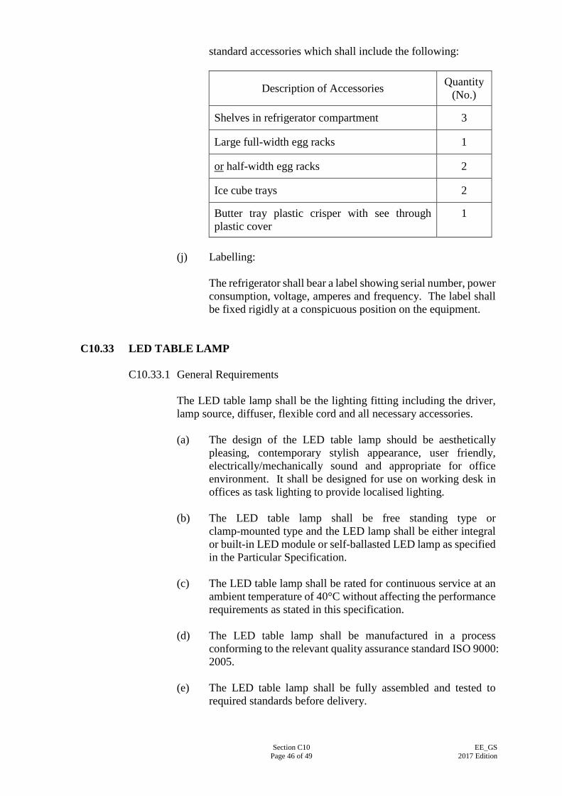
Section C10 Page 46 of 49
EE_GS 2017 Edition
standard accessories which shall include the following:
Description of Accessories Quantity (No.)
Shelves in refrigerator compartment 3
Large full-width egg racks 1
or half-width egg racks 2
Ice cube trays 2
Butter tray plastic crisper with see through plastic cover
1
(j) Labelling:
The refrigerator shall bear a label showing serial number, power consumption, voltage, amperes and frequency. The label shall be fixed rigidly at a conspicuous position on the equipment.
C10.33 LED TABLE LAMP
C10.33.1 General Requirements
The LED table lamp shall be the lighting fitting including the driver, lamp source, diffuser, flexible cord and all necessary accessories. (a) The design of the LED table lamp should be aesthetically
pleasing, contemporary stylish appearance, user friendly, electrically/mechanically sound and appropriate for office environment. It shall be designed for use on working desk in offices as task lighting to provide localised lighting.
(b) The LED table lamp shall be free standing type or
clamp-mounted type and the LED lamp shall be either integral or built-in LED module or self-ballasted LED lamp as specified in the Particular Specification.
(c) The LED table lamp shall be rated for continuous service at an
ambient temperature of 40°C without affecting the performance requirements as stated in this specification.
(d) The LED table lamp shall be manufactured in a process
conforming to the relevant quality assurance standard ISO 9000: 2005.
(e) The LED table lamp shall be fully assembled and tested to
required standards before delivery.
Section C10 Page 47 of 49
EE_GS 2017 Edition
C10.33.2 Safety Requirements (a) The LED table lamp shall comply with IEC 60598-2-4:1997. (b) The LED table lamp shall be ‘Restriction of Hazardous
Substances (RoHS)’ compliance. (c) The LED table lamp shall comply with the risk group ‘Exempt
Group (RG 0)’ of IEC 62471:2006 – Photobiological safety of lamps and lamp system.
(d) The LED table lamp shall be suitably protected from electric
shock and shall comply with the latest edition of the Guidance Notes for the Electrical Product (Safety) Regulation.
C10.33.3 Performance Requirements
(a) The LED table lamp shall have locally on/off or dimmable
on/off switch that is easily reachable by user. For the light output to be dimmable as specified in the Particular Specification, the light output shall be continuous dimmable or at least 3-step discrete dimmable settings ranging from 40-100% without flickering.
(b) The LED table lamp shall comply with the following
performance requirements: (i) Luminaire efficacy not lower than 30 lumen/watt
including the ballast, thermal and lighting fixture losses. (ii) Colour Rendering Index (CRI) not lower than 80. (iii) For lumen maintenance requirements of the LED table
lamp, it shall comply with clause C9.4.1(b). (iv) The nominal Correlated Colour Temperature (CCT)
shall be 4,000K. (v) Power factor not lower than 0.85 and 0.6 for built-in
LED module and self-ballasted LED lamp respectively. (c) The LED table lamp source shall have suitable cover and/or
diffuser built-in for glare control. The LED lamp source shall not be directly visible to the user when it is positioned at 600 mm above desk level.
C10.33.4 Electrical Requirements
(a) The LED table lamp, including the electronic driver and LED
module, shall be suitable for operation at 220 V±6%, 50 Hz±2%, single phase, AC supply.
Section C10 Page 48 of 49
EE_GS 2017 Edition
(b) Where the offered LED table lamp is to receive extra low voltage DC input by using external driver, provision of an electrical switch at convenient position that can readily accessible from the desk chair shall be provided to switch off the luminaire.
(c) The LED table lamp shall have minimum 2 metres of ordinary
duty rubber insulated and sheathed flexible cord, 3-core with minimum cross sectional area of 0.75 mm², in conformance with B.S. 6500 or IEC 60245.
(d) Suitable rated fuse protection shall be provided in the 13
Ampere socket plug to B.S. 1363-1:1995/ A4:2012 which shall be permanently connected to each of the LED table lamp.
(e) The LED driver and the extra low voltage DC driver shall
comply with the following standards where applicable: (i) IEC 61347-1:2015 Lamp controlgear – Part 1: General
and safety requirements; (ii) IEC 61347-2-13:2014 Lamp controlgear – Part 2-13:
Particular requirements for DC or AC supplied electronic controlgear for LED modules;
(iii) IEC 62384:2011 DC or AC supplied electronic control
gear for LED modules – Performance requirements; (iv) IEC 61000-3-2:2014/ Corr 1:2009 Electromagnetic
compatibility (EMC) – Part 3-2: Limits – Limits for harmonic current emissions (equipment input current≦16 A per phase);
(v) IEC 61547:2009 Equipment for general lighting
purposes – EMC immunity requirements; and (vi) BS EN 55015:2013/A1:2015 Limits and methods of
measurement of radio disturbance characteristics of electrical lighting and similar equipment.
(f) The Light Emitted Diode (LED) module shall comply
IEC 62031:2014 LED modules for general lighting – Safety specifications, for the part of “LED modules without integral control gear for operation under constant voltage, constant current or constant power”.
C10.33.5 Mechanical Requirements
(a) The LED table lamp shall have adjustable outreach arm for free
adjustment of lighting angle by the user such that the LED lamp head can tilt and swivel in two axes to achieve an optimal ergonomic position.
Section C10 Page 49 of 49
EE_GS 2017 Edition
(b) The design of the outreach arm should have suitable length and
flexibility to suit the intended application without obstruction to the user.
(c) The hinges and/or springs for adjustment of outreach arm
and/or angle of lamp head shall be robust for frequent adjustment and can hold the lamp head in sturdy position after adjustment.
(d) The materials of the adjustable arm shall be mechanically sound
and durable. No sharp edges shall be present. (e) The LED table lamp shall be self-balanced with the out
reaching arm fully extended.
C10.33.6 Testing Standards for Compliance
The relevant requirements as stated in clause C10.33.1 – C10.33.4 of the LED table lamp shall be tested and certified by the accredited laboratories. The test reports shall be submitted for approval.

Section C11 Page 1 of 11
EE_GS 2017 Edition
SECTION C11
LOW VOLTAGE CUBICLE SWITCHBOARD
C11.1 GENERAL This Section covers the design, supply and installation of verified power switchgear and controlgear assembly of Low Voltage Cubicle Switchboard (hereafter called the Switchboard).
C11.2 DESIGN REQUIREMENTS Unless otherwise specified, the scope of work shall include the design of the Switchboard and selection of equipment and components including due consideration of other components of the Electrical and other Installations to ensure that the Switchboard conforms to the specified requirements. All design works including relevant information, data and calculations shall be submitted to the Supervising Officer for approval.
C11.3 PERFORMANCE REQUIREMENTS The Switchboard shall comply with IEC 61439-2:2011. All materials and workmanship shall comply, where applicable, with all relevant IEC, B.S. or EN Standards and all relevant sections of this Specification. The Switchboard shall comply with the electromagnetic compatibility requirement of IEC 61439-1:2011unless the exemption conditions stipulated in Clause J9.4.2 of Annex J of IEC 61439-1:2011 are satisfied. The Works shall be carried out in a manner consistent with good practice in Hong Kong. The Switchboard shall be of multi-cubicle type assembled from compartments housing the busbars, switches, etc. as shown on the Drawings, suitable for service conditions detailed in Clause C11.6 of this Specification and complying where relevant, with the appropriate Standards and Codes of Practice listed in this Specification. Where an alternative standard is proposed, the tenderer shall prove by means of adequate supporting documents that the alternative standard meets the requirements of the relevant Standard. The Switchboard comprising a combination of one or more low-voltage switching devices together with associated control, measuring, signalling, protective, regulating equipment, etc., shall be completely assembled with all the internal electrical and mechanical interconnection and structural parts.
Section C11 Page 2 of 11
EE_GS 2017 Edition
C11.4 CONSTRUCTION AND FINISH The Switchboard shall be constructed from steel, self supporting, so formed as to give a rigid and robust construction without cross-struts, and shall be structurally, mechanically and electrically sound, with cubicle top, panels and doors of sheet steel or the equivalent metal, not less than 2 mm in thickness. The Switchboard shall have clear accessibility to all internal components within it. Steel work shall be treated to prevent corrosion before being painted. Steel parts, normally left bright, shall be corrosion resistance plated. The bottom of the Switchboard shall be closed and made to vermin-proof by means of non-magnetic, fire-proof barrier plates cut away where required to suit the cables as specified. In general, the Switchboard shall be suitable for indoor use to IP31 as specified in IEC 60529:2013/ Corr 2:2015. In the event that top entry cabling facilities are required, the top of the Switchboard shall also be constructed in like manner. Detachable panels at the back of the Switchboard shall each be provided with a pair of handles for easy fixing/removal of the panels. The Switchboard shall be of uniform height and uniform depth front-to-back, throughout its length and shall present a neat and tidy appearance. Unless otherwise specified, the internal separation of the Switchboard shall be constructed generally to Form 3b of IEC 61439-2:2011. The switch/control units in each cubicle shall be arranged to form a multi-tier arrangement. The compartment for housing the incoming/outgoing terminals for external conductors shall have ample dimensions for accommodating the external conductors, including space for spreading of the cores. Suitable mounting brackets or cable supports shall be provided to prevent the terminals or cables being subjected to stresses which may reduce their normal life or performance. All switches shall be provided with mechanical interlocks so that their doors, covers, and the like can only be opened when the switches are in the off position and it shall not be possible to close the switches while the doors, covers and the like are opened, except by overriding the interlock or using a tool. The interlock shall automatically be restored on reclosing the doors, covers and the like. The exterior of each Switchboard shall be finished to a light grey or the manufacturer’s nearest standard colour. The end plates shall be of non-corrosive type and finished to match with the colour of the switchboard whereas the external fixing bolts and set screws shall be of chrome-plated finish or equivalent anti-corrosion treatment. The "space" provision for future outgoing circuits shall comprise blank panels, undrilled, and provision for accommodating fuseswitches and/or circuit breakers. Busbars shall be extended as necessary and drilled for future connection of conductors. The spaces scheduled or shown on the Drawings are indicative of
Section C11 Page 3 of 11
EE_GS 2017 Edition
minimum requirements and may be varied to suit the arrangement offered, subject to approval.
C11.5 ELECTRICITY CHARACTERISTICS OF THE SWITCHBOARD The electrical characteristics of the Switchboard shall be as follows unless otherwise specified: (a) Rated operational voltage : 380/220 V + 6%, 3-phase, 4-wire,
50 Hz., + 2%, AC; (b) Neutral earthing : Solid at transformer; (c) Rated short-time
withstand current : 50 kA for 1 second withstanding current;
and (d) Power factor : Incoming 0.25 lagging.
C11.6 SERVICE CONDITIONS The service conditions stipulated in Clause C5.1.2 of this Specification shall be applicable. The Switchboard shall only be provided with the built-in natural cooling facilities as furnished in accordance with the recommendations endorsed by the short circuit testing organisation to suit the service conditions specified.
C11.7 BUSBARS, WIRING AND EARTHING The busbar chamber shall contain triple phase and neutral busbars of equal cross-sectional areas rated as shown on the Drawings or specified elsewhere. The configuration of the busbar assembly contained in the Switchboard shall be the same as shown on the verification test drawings. Any change in the configuration will require separate verification test certificates unless substantiation is submitted by the EE Contractor and approved by the Supervising Officer. All busbars shall be made of hard drawn high conductivity copper to BS EN 13601:2013 and shall be electro-tinned. Construction, marking and arrangement of the busbars, connections and auxiliary wiring shall be to IEC 61439-1:2011. External busbars for connection to the Switchboard shall be fully insulated and arranged in such a manner that they will not obstruct access to other equipment. All neutral conductors shall have cross-sectional areas not less than that of the respective phase conductors. The phase and neutral conductors shall be identified by the colour brown, black, grey and blue respectively. Whenever a vertical section of the Switchboard contains more than one outgoing
Section C11 Page 4 of 11
EE_GS 2017 Edition
circuit, busbar risers or droppers to which the outgoing circuits are connected shall be provided and shall be arranged in such manner that an internal short-circuit is not to be expected under normal operating conditions. The rating of the vertical busbar riser or dropper serving the multi-tier switchgears of a vertical section of a Switchboard shall be not less than the total rated current of all connected outgoing units including spare and space outgoing units or the current rating of the upstream protective device protecting the vertical busbar riser or dropper, whichever is the less. Insulators and busbar supports shall be non-hygroscopic and non-deteriorating. The use of fibrous materials, linseed oil, varnish, etc. is prohibited. All auxiliary circuit wiring shall be PVC-insulated with designated conductor temperature of 90oC to BS 6231:2006. They shall, wherever possible, be grouped and placed together in a neat manner. Different insulant colours shall be provided to distinguish the various circuits at different voltage. All wires shall also have at both ends a coded ferrule of insulating materials permanently marked with suitable characters and codes. Each connection shall terminate at an approved type of terminal block, which shall also be suitably labelled. Cable for auxiliary circuits shall be run inside cable compartments or special cable ways designed to provide adequate protection against mechanical damage. They shall also be bunched neatly and be identifiable throughout their length of run. Wiring from the fixed part of the Switchboard to the movable part, such as hinged door, shall be enclosed by a flexible PVC tubing. If apparatus with a voltage exceeding the limits of extra-low voltage are attached to lid, door, etc., the continuity of the protective circuits shall be ensured in accordance with Clause 8.4.3.2.2 of IEC 61439-1:2011. Connectors or soldered joints are not permitted in the auxiliary circuit wiring. Exposed live terminals shall be suitably shrouded or covered. A continuous tinned copper earthing bar of adequate rating per Clause 8.4.3.2 of IEC 61439-1:2011 shall be fixed at the rear interior, bottom portion throughout the length of the switchboard, bonding the framework of all modular sections. An earthing terminal shall be provided at the external portion of the Switchboard suitable for the connection of 25 x 3 mm copper tape. The position of the earthing terminal shall be subject to the approval of the Supervising Officer.
C11.8 CIRCUIT BREAKERS, FUSESWITCHES AND CHANGEOVER SWITCHES Unless otherwise specified, circuit breakers (including ACB, MCCB), fuseswitches (including switchfuses), and changeover switches shall comply with the requirements stipulated in Section C5 of this Specification. The MCCB shall be withdrawal or plug-in type if its rating is 100A 3-phase or above. Circuit breakers shall have the breaking capacity to withstand the prospective fault level at the switchboard.
Section C11 Page 5 of 11
EE_GS 2017 Edition
C11.9 METERING, PROTECTIVE RELAYS AND INDICATING LAMPS
Metering facilities shall be provided for incoming and outgoing circuits. Unless otherwise specified, Digital Power Analyser complying with Clause C5.24 of this Specification should be used for main incoming circuits and Digital Multifunction Power Meter complying with Clause C5.20 of this Specification should be used for outgoing circuits. Supply healthy indicating lamps shall be provided at every main incoming circuit breaker or switch. Wiring from the measuring devices shall be brought out and be terminated in approved type of rail-mounted termination/feed through blocks housed inside separate compartments accessible from the front. Test plugs shall also be provided at each termination points to measure the voltages and/or currents flowing in that particular measuring circuit by external testing instruments. Instruments, meters and relays shall be of the flush mounted pattern, with bezels black finished, positioned on the front of the Switchboard. All terminals shall be suitably insulated and potential circuits shall be suitably fused, using H.R.C. fuses. Separate current transformers (CT) in compliance with IEC 61869-2:2012 shall be used for measuring and protection applications. Current transformers shall have accuracy Class of "3" or better for use with ammeters, "1" or better for use with Watt-hour meters and "10P" or better for protection applications. The product of rated accuracy limit factor and rated output of the protection CT shall not be less than 10 times the total rated burden of the trip circuit including the relays, connection leads and overcurrent release where applicable. Current transformers shall be mounted without reduction of area of busbars or connections and be arranged for easy removal. Protective relays shall be to IEC 60255-1:2009 and of the type as shown on the Drawings or as specified. Where a protective relay consists of multi-elements, suitable labels shall be provided to indicate the phases to which the corresponding elements are connected. Indicating lights shall be LED type of diameter minimum 22mm operating at 24V AC/DC. The service life of indicating light shall be at least 100,000 hours at rated voltage and 25°C. All air circuit breakers other than those used for controlling the incoming supply and unless specified, shall have overcurrent tripping facilities to give time delay overload current protection and instantaneous short circuit interruption. The time-current characteristics shall be submitted for inspection. Shunt trip coils operated by power supply from the mains shall not be used. For air circuit breakers controlling the incoming supply to the Switchboard, the circuit protection shall be provided by the following devices: (a) Electromechanical Type I.D.M.T. Overcurrent Protection Relay:
Section C11 Page 6 of 11
EE_GS 2017 Edition
This relay shall have triple elements with current setting ranging from 50% to 200% in 25% tappings and with time setting from 0 to 1.3 seconds in variable steps. The relay shall be of draw-out-case type flush mounted on the front panel. The characteristic of the relay shall match with that of the Supply Company;
(b) Electromechanical Type I.D.M.T. Earth Fault Relay:
One single pole earth fault relay with current setting from 10% to 40% in 5% tappings and with time setting from 0 to 1.3 seconds. The relay shall be of draw-out-case type, flush mounted on the front panel. The characteristic of the relay shall match with that of the Supply Company; and
(c) Shunt-Trip Release:
It shall be operated by a DC supply of 24 V or 30 V++ obtained from the secondary batteries complete with battery charger, etc. of suitable rating. ++ Note: Other voltages may be specified to suit particular project.
Alternatively, Digital Protection Relay complying with Clause C5.23 of this Specification can also be used.
C11.10 SUPPLY COMPANY METERING Provision shall be made, where specified and/or shown on the Drawings, for the accommodation of the Supply Company's metering equipment upon the Switchboard. The metering equipment will be supplied and mounted by the Supply Company on Site. The metering compartment shall be complete with a hinged glazed door for meter viewing. The accommodation for the Supply Company's metering equipment shall include a suitable insulating panel for mounting the meters and suitable fuses to protect the voltage coil circuits to each meter. The "mains" side of the fuseholders shall be wired to the incoming supply mains. Fuses shall be of the H.R.C. type rated at 6 A, with provision for sealing to prevent unauthorised removal. The Switchboard shall also be provided with suitable provisions of C.T. Chambers for mounting the Supply Company's current transformers (C.T.s) in accessible positions. Wiring between the current transformers and the meters will be carried out by the Supply Company on Site, but adequate and appropriate cabling facilities for installing the said wiring shall be provided in the Switchboard.
C11.11 LABELS Laminated self-coloured material labels of ample sizes shall be provided for each of the units both at the front and in the cabling compartment on the Switchboard,
Section C11 Page 7 of 11
EE_GS 2017 Edition
engraved in English and Chinese characters. A means of fixing these labels shall be provided other than by adhesives. During the progress of manufacture of the Switchboard, a schedule of labels shall be submitted for approval before engraving is carried out. Warning labels shall be affixed to the rear panels and shall be coloured red with white lettering in both English and Chinese characters denoting ‘DANGER- LIVE BUSBARS INSIDE/ 危險 – 內有帶電匯流排’. Similar warning labels shall be affixed at the front and in the cabling compartment for each automatic/remote closing or changeover switching denoting Beware-automatic closing/注意 – 自動接合 in English and Chinese characters. In addition to automatic screening shutters and barriers, warning labels shall also be provided for all live parts, such as test terminal blocks. The Switchboard shall be provided with one or more plates, marked in a durable manner and located at a conspicuous place such that they are visible and legible when the Switchboard is installed. The following information shall be given on the nameplates: The manufacturer’s name;
(a) Type designation or identification number or other means of identification making it possible to obtain relevant information from the manufacturer;
(b) IEC 61439-2:2011;
(c) Rated current;
(d) Rated operation voltage (and frequency in case of AC);
(e) Rated insulation voltage;
(f) Short-circuit withstand strength;
(g) Degree of protection; and
(h) Rating of main busbars.
(i) Rating of main busbars.
C11.12 CABLE ARRANGEMENTS The Switchboard shall be provided with all necessary cable lugs, etc., fixed in positions on mounting plates and straps, to suit the types and directions of entry of the cables as shown on the Drawings or as specified. Cable conductors for all circuits within the Switchboard shall be arranged in a tidy manner and mechanically secured at regular intervals such that any movement occurring to the conductors, either under normal operation conditions (e.g. thermal expansion, vibration, etc.) or due to short circuit in any one of the circuits, shall not cause any damage or short circuit to any healthy bare live parts in the Switchboard.
Section C11 Page 8 of 11
EE_GS 2017 Edition
C11.13 AUTOMATIC INTERLOCKING FACILITY When automatic interlocking facility is specified or shown on the Drawings, the design shall be that it is safe, reliable and well proven. Unless otherwise approved by the Supervising Officer, the mechanical part of the automatic interlocking facility shall be of rod-type design to ensure a safe and reliable interlocking system. For locally assembly switchboard containing automatic interlocking facility, the interlocking design shall be endorsed by the respective licenser.
C11.14 ANCILLARY EQUIPMENT The Switchboard shall be supplied complete with one hydraulic operated handling truck in the main switchroom suitable for handling all sizes of air circuit breakers on the Switchboard, and one set of portable earthing equipment for each main incoming air circuit breaker. Portable earthing leads will not be accepted as an alternative to the earthing equipment. The battery charger/battery sets shall comply with the requirements of Clause C5.21 of this Specification unless otherwise specified below. The battery charger and batteries shall be housed in separate enclosures from the Switchboard and shall be the same type of enclosures as the Switchboard. All secondary batteries to be supplied with the Switchboard shall be of the nickel-metal-hydride type, sealed or ventilated, requiring little or no maintenance and having long life. The capacity of the batteries, with charger disconnected, shall be adequate to trip the associated air circuit breaker(s) consecutively at least 20 times. In case there are more than one air circuit breakers being tripped by the same bank of batteries, the batteries shall be capable of tripping at least two air circuit breakers simultaneously. Site tests shall be carried out for the charger and battery set after completion of the installations and the connection of the permanent supply according to the manufacturer’s instruction in the presence of the Supervising Officer’s inspectorate staff and in accordance with Section D1 of this Specification. The Switchboard shall be supplied complete with all operating handles, jigs, etc. required for the normal charging, closing, opening, racking in and out operations of all circuit breakers of the Switchboard and shall be properly fixed in a neat manner on a wooden board with brass hooks inside the main switch room where the Switchboard is installed. The Switchboard shall be provided with two rubber mats of ribbed surface, complying with IEC 61111:2009, laid in front of and at the rear of the Switchboard. The rubber mats shall be continuous sheets of minimum thickness of 10 mm, each of same length as the Switchboard and minimum width of not less than 1,000 mm or the width of the space between the front or back of the Switchboard to the adjacent wall. The Switchboard shall be provided with one complete spare set of fuses equal in number for each rating of fuses in all switch-fuses and fuse-switches and fitted in a conveniently accessible position on wooden board(s) in the relevant Main Switchroom. The spare fuses should be appropriately covered to prevent the contacts from rusting due to corrosion.
Section C11 Page 9 of 11
EE_GS 2017 Edition
C11.15 Certification and Verification Test
Verification testing of typical Switchboard to IEC 61439-2:2011 shall be carried out by a competent and independent short circuit testing organisation internationally recognised as having equal standing as The Association of Short Circuit Testing Authorities (ASTA). The verification report issued by the testing organisation shall be submitted to the Supervising Officer for record. Appropriate technical information and litreature in English and copies of the verification test certificates and drawings must be made available for examination. Temperature rise limits test of typical Switchboard shall be verified to IEC 61439-1:2011. The whole busbars, including the conductors connecting the busbars to each outgoing circuit, shall be arranged to withstand short-circuit at any point. All conductors between the main busbars/droppers and the outgoing protective devices not short-circuit type tested to a fault current of 50 kA for 1 second at 0.25 lagging power factor shall be insulated by approved means to comply with the requirement that ‘an internal short-circuit between phases and/or between phases and earth is only a remote possibility’ as stipulated in Clause 8.6.4 of IEC 61439-1:2011. If modifications are made to a verified Switchboard, clause 10 of IEC 61439-1: 2011 shall be used to check if these modifications will affect the performance of the Switchboard. New verifications shall be carried out if an adverse effect is likely to occur and the method of ‘verification testing’ shall be used. The following certification bodies shall be considered eligible to be third party design checker for assessment and verification of switchboard design employing design calculation approach as allowed in IEC 61439-2: (a) Certification bodies recognised by the Director of Electrical and
Mechanical Services as Recognised Certification Bodies for testing of Low Voltage switchgear and control gear assemblies;
(b) A competent and independent short circuit testing organisation internationally recognised as having equal status as The Association of Short Circuit Testing Authorities (ASTA); or
(c) Local academia specializing in electrical engineering work.
A functional unit (ACB, MCCB, switchfuse, fuseswitch and changeover switch) in the verified Switchboard may be substituted with a similar unit of the same manufacturer used in the original verification provided the following conditions are satisfied and subject to the approval of the Supervising Officer:-
(i) Power loss and terminal temperature rise of the functional unit when tested
in accordance with its product standard, is the same or lower;
(ii) The physical arrangement within the Switchboard shall be maintained;
(iii) The rating of the Switchboard shall be maintained; and
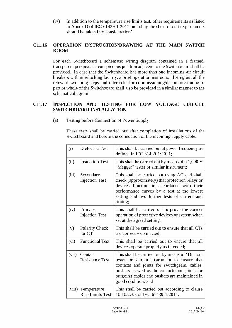
Section C11 Page 10 of 11
EE_GS 2017 Edition
(iv) In addition to the temperature rise limits test, other requirements as listed in Annex D of IEC 61439-1:2011 including the short-circuit requirements should be taken into consideration’
C11.16 OPERATION INSTRUCTION/DRAWING AT THE MAIN SWITCH
ROOM For each Switchboard a schematic wiring diagram contained in a framed, transparent perspex at a conspicuous position adjacent to the Switchboard shall be provided. In case that the Switchboard has more than one incoming air circuit breakers with interlocking facility, a brief operation instruction listing out all the relevant switching steps and interlocks for commissioning/decommissioning of part or whole of the Switchboard shall also be provided in a similar manner to the schematic diagram.
C11.17 INSPECTION AND TESTING FOR LOW VOLTAGE CUBICLE SWITCHBOARD INSTALLATION
(a) Testing before Connection of Power Supply
These tests shall be carried out after completion of installations of the Switchboard and before the connection of the incoming supply cable. (i) Dielectric Test This shall be carried out at power frequency as
defined in IEC 61439-1:2011;
(ii) Insulation Test This shall be carried out by means of a 1,000 V "Megger" tester or similar instrument;
(iii) Secondary Injection Test
This shall be carried out using AC and shall check (approximately) that protection relays or devices function in accordance with their performance curves by a test at the lowest setting and two further tests of current and timing;
(iv) Primary Injection Test
This shall be carried out to prove the correct operation of protective devices or system when set at the agreed setting;
(v) Polarity Check for CT
This shall be carried out to ensure that all CTs are correctly connected;
(vi) Functional Test This shall be carried out to ensure that all devices operate properly as intended;
(vii) Contact Resistance Test
This shall be carried out by means of "Ductor" tester or similar instrument to ensure that contacts and joints for switchgears, cables, busbars as well as the contacts and joints for outgoing cables and busbars are maintained in good condition; and
(viii) Temperature Rise Limits Test
This shall be carried out according to clause 10.10.2.3.5 of IEC 61439-1:2011.
Section C11 Page 11 of 11
EE_GS 2017 Edition
Note: Tests (i) to (iii) and (v) to (vii) must be carried out on site and tests (iv) and (viii) can be carried out in factory.
(b) Testing after Connection of Supply
The following tests shall be carried out after the incoming supply cables are connected and the “Switchboard” successfully commissioned on no load: (i) Phase-to-phase voltage test; (ii) Phase-to-neutral voltage test; (iii) Phase-to-earth voltage test; (iv) Neutral-to-earth voltage test; and (v) Phase sequence test on each and every outgoing circuit.
All tests shall be witnessed by and carried out to the satisfaction of the Supervising Officer and all test results must be submitted in quadruplicate to the Supervising Officer for record purposes.
C11.18 REQUIREMENTS DURING MAINTENANCE PERIOD Requirements during maintenance period are specified in Section E3 of this Specification.
Section C12 Page 1 of 30
EE_GS 2017 Edition
SECTION C12
DIESEL GENERATING SET INSTALLATION
C12.1 REQUIREMENTS OF DIESEL GENERATING SETS C12.1.1 Generating Set Rating
Each diesel generating set shall be of 3 phase, 4 wire output and rated at 50 Hertz, 380 V, 0.8 power factor lagging. Each generating set shall comply with ISO 8528:2005 and shall be of Prime Power (PRP) rating for the transient as well as the steady state power requirements of the connected essential loads. Offers based on standby rating will not be considered. The actual rating of each generating set shall be clearly indicated on the name plate fixed on the generating set.
C12.1.2 General Requirements of Diesel Engine
(a) The engine shall be a fresh water-cooled, four stroke, direct
injection, naturally aspirated or pressure charged, diesel engine of industrial type complying with the requirements of all parts of ISO 8528:2005 and continuously rated to meet the load requirements under site conditions at a crank shaft speed not exceeding 1500 rpm, and suitable for running on "Ultra Low Sulphur Diesel” (ULSD) fuel to BS EN 590:2013.
(b) The engine shall be complete with the following equipment :-
(i) Engine mounted instrument panel, incorporating lubrication oil pressure gauge, lubrication oil temperature gauge, cooling water outlet temperature gauge, tachometer and hour-meter. The tachometer shall sense the actual engine speed. Frequency sensing type is not acceptable. Ammeter indicating the charging rate of the engine driven dynamo shall also be provided;
(ii) Protective screens for flywheel, and coupling (if
exposed) and other exposed moving parts; (iii) Engine cooling system incorporating engine driven
water circulating pump, thermostatically controlled water temperature regulating device, and engine driven tropicalized radiator with mechanically driven fan;
(iv) Air cleaner of the dry type or 'oil bath' type incorporating
replaceable element; (v) Lubricating oil system (full flow, replaceable element
type filter);
Section C12 Page 2 of 30
EE_GS 2017 Edition
(vi) Fuel oil system comprising filter, fuel transfer pump, injection pump and injectors;
(vii) Governor with manual adjustment of +5% of normal
speed. The governing accuracy shall comply with performance Class G3 in ISO 8528-2:2005 "Specification for Reciprocating Internal Combustion Engines, Performance - Speed governing". Governor shall sense the actual engine rotation. Governor designed for sensing the frequency of generator output voltage is not acceptable;
(viii) Fuel control solenoid (electrically operated) together
with an emergency fuel shut off valve (manually operated);
(ix) Two stage engine protective devices for high cooling
water temperature and low lubricating oil pressure. Engine over-speed protective device shall also be provided. The engine over-speed sensor shall sense the actual engine rotating speed and shall be free from harmonic interference;
(x) All wiring of the control and protection systems, carried
out in suitable heat and oil resisting cable, shall be wired out to a suitable cable termination block; and
(xi) Earth terminal for bonding the engine and alternator to
the earthing system.
(c) In accordance with ISO 8528:2005, an additional engine power of 10% of the rated power of the generating set shall be provided for governing purpose only (e.g. transient load conditions and suddenly applied loads).
(d) The difference in height between the generator set and the daily
service tank shall not exceed the maximum value recommended by the generator set manufacturer.
The equipment and accessories to be installed and the details of the fuel oil supply system shall be subject to the approval of the Supervising Officer.
(e) If an underground fuel oil storage-tank is installed, the
associated piping, fittings and accessories shall be installed as required to complete the fuel oil system of the generator set. The underground fuel oil storage tank shall be complete with float control and other necessary accessories. A solenoid control valve energised by the starting circuit shall be installed in the fuel oil pipe from the daily service tank to the storage tank.
Section C12 Page 3 of 30
EE_GS 2017 Edition
C12.1.3 General Requirements of Alternator (a) The alternator shall be of self-exciting, self regulating and
brushless type, complete with permanent magnet exciter and shall comply generally with the requirements of ISO 8528-3:2005.
(b) The voltage regulation of the alternator apart from satisfying
the requirements of the electrical loads as specified in terms of steady state and transient conditions shall be of three phase sensing type.
The steady state and transient behaviour shall comply with performance Class G3 in ISO 8528-5:2013 The maximum percentage of voltage dip shall not exceed 20% of the rated value under all loading conditions including step load application. In case that electronic equipment and computers form a substantial amount of supply loads, the maximum voltage dip shall not exceed 10%.
(c) The machine shall be constructed with the type of enclosure to
IP21 as specified in IEC 60529:2013/ Corr 2:2015. Anti-condensation heating elements bounded to the winding of the alternator and suitable for connection to the mains electricity supply (220 V) shall be fitted to the alternator. The anti-condensation heaters should be thermostatically controlled and arranged to cut off when the alternator is in operation. They shall be easily accessible for maintenance and replacement.
(d) A termination box shall be provided suitable for
accommodating and terminating cables or busbar trunking entering from the bottom, sides or top. If busbar trunking is used for power-feeder between the alternator and switchboard, special provision shall be made to prevent the vibration of the diesel generating set affecting the tightness of the terminations. Due to site condition, cable termination may only be made at a particular side of the alternator.
(e) The rating assigned to the alternator by the manufacturer shall
be of maximum continuous rating. (f) The alternator shall be provided with winding insulation of
class H, but it shall be designed to operate continuously at temperature class F rating in accordance with IEC 60085:2007.
C12.1.4 Starting System
Electrical battery starting system for each diesel generating set with a set of 24 V electric starting equipment comprising starter motor, battery charger, starting battery and all necessary wiring and switchgear shall be provided. The battery shall be of the nickel cadmium type, with clear plastic cases complete with a hardwood floor stand with hardwood cover suitable for installation adjacent to the
Section C12 Page 4 of 30
EE_GS 2017 Edition
starter motor. The battery shall be rated to give six engine cranking cycles each of six seconds within a 60 second period. The battery shall also be capable of providing adequate power to supply the control circuit and to trip the main MCCB/ACB. Separate batteries shall be provided for engine starting and the shunt trip coil if their operating voltages are different. The connection bars of the batteries shall be protected with corrosion resistant petroleum jelly. A suitable double pole switch should be provided to isolate the supply from the battery to the engine starter unit. The battery charger shall be of 2 rate charging and of constant voltage type installed in the control cubicle, and arranged to maintain the batteries in fully charged condition. In addition, when the engine is running, the batteries shall be charged by an engine driven dynamo controlled by an AVR and cut out. The battery charger shall be capable of charging up to 75% battery capacity specified in the previous paragraph in 6 hours. Current limiting device shall be provided to limit the charging current with the limit recommended by the battery manufacturer.
C12.1.5 Electrical Loads The electrical loads to be connected to the diesel generating set will be of continuous duty-type. Motor loads will be designated as S1 in accordance with IEC 60034-1:2014. Thyristor controlled lifts and other thyristor loading such as uninterrupted power supply (UPS), variable voltage variable frequency speed controller (VVVF) etc. will be connected to some of the generators. High current harmonics are generated by these thyristor loading which could have adverse effects on the diesel generating sets on voltage distortion, system instability, overheating of buffer windings, etc. The generator design shall take necessary precautions (including the provision of engine overspeed sensing device free from harmonic interference, etc.) to guard against the occurrence of the above adverse effects caused by the harmonics. In addition, the generator sets shall be able to tolerate a reasonable amount of lift regenerative power. The generator set shall be suitably sized to cater for the possible regenerative power. Appropriate dummy loads and associated accessories shall be provided, if necessary, for the absorption of the excessive regenerative power.
C12.1.6 Suitability for Cold Starting and Step Load Acceptance The generating set shall be suitable for cold starting and for the acceptance of step loads immediately after attaining normal voltage and frequency.
Section C12 Page 5 of 30
EE_GS 2017 Edition
C12.1.7 Radio Interference Suppression The alternator shall be fully equipped for radio interference suppression to BS EN 55014-2:2015/ BS EN 55014-1:2006/ A2:2011.
C12.1.8 Painting All exposed ferrous metal surfaces of the machines, under-frame and auxiliary equipment shall, where applicable, be treated with rust-inhibiting primer paint, undercoat and finishing coat. Hot face parts shall be coated with heat resisting paint work which can tolerate high temperature up to 650oC without deterioration.
C12.1.9 Baseframe Assembly The generating set shall comprise a diesel engine directly coupled to an alternator and mounted in line on a steel section baseframe. This diesel alternator baseframe shall be provided with anti-vibration mountings complete with holding down of adequate strength bolts and nuts for installation onto a concrete plinth. The complete assembly shall be equipped with four lifting eyes to facilitate lifting and transporting. Grouting shall not be carried out until the final agreement from the Supervising Officer. Grout shall be composed of equal parts of cement and fine granular sand mixed with fresh water.
C12.1.10 Welding All welding shall be carried out only by welders of the recognised proficiency. The welding electrodes, equipment and process shall also be in accordance with BS EN 1011-2:2001, BS 1821:1982 and BS 2640:1982 for arc welding or oxy-acetylene welding respectively. Welding shall not be carried out under unfavorable conditions. All welded surfaces shall be clean and dry before any welding is to be done.
C12.1.11 Structural Steel Structural steel used shall comply with BS 7668:2004 Grade S345J0WPH. All forms of steel used shall be of standard section with dimensions, tolerances and properties complying with BS 4-1:2005. Supplier of structural steel work shall provide certificates of the material. All exposed edges shall be ground to produce a chamfer not less than 2 mm in width to ensure proper adherence of paint.
Section C12 Page 6 of 30
EE_GS 2017 Edition
C12.2 CONSTRUCTION OF CONTROL CUBICLE
C12.2.1 The control cubicle shall be of totally enclosed type and meet the requirements of IP44 as specified in IEC 60529:2013/ Corr 2:2015 enclosures. The cubicle shall be painted against corrosion after completion of all drilling and operation.
C12.2.2 All control cubicles shall have labels made from laminated self-coloured materials and engraved with descriptions in both English and Chinese to be agreed by Supervising Officer's Representative. Fixing of labels shall be by mechanical means.
C12.2.3 The contactors, switch fuses, relays and all other necessary items shall be housed in the appropriate control panel which shall be arranged with front access for maintenance. It shall also be lockable to prevent unauthorised access and malicious damage to the equipment inside.
C12.2.4 Each relay shall be labelled appropriately to its service either by function or by code, in which case a code index shall be securely attached to the panel for easy and positive identification.
C12.2.5 A control cubicle shall be installed for each diesel generating set.
C12.2.6 All circuits shall be accommodated in accordance with IEC 61439-1:2011.
C12.2.7 The cubicle shall be equipped with anti-condensation heater which shall be thermostatically controlled.
C12.2.8 The cubicle shall have adequate space mountings for cable terminal box or boxes suitable for armoured cables or busbar entering and leaving both at the top and the bottom of the control cubicle, for connection of mains feeders.
C12.2.9 Terminal blocks and provision for conduit termination shall be provided for small outgoing wiring. All small wiring shall be appropriately ferruled and coded for identification.
C12.2.10 The cubicle shall be so partitioned to allow maintenance of the panel in a safe manner without interrupting the power supply from the mains to the external loads.
C12.2.11 The cubicle shall be constructed to Form 3b of IEC 61439-2:2011.
C12.2.12 The cubicle shall be provided with two rubber mats of ribbed surface,
complying to IEC 61111:2009 , laid in front of and at the rear of the cubicle. The rubber mats shall be continuous sheets of minimum thickness of 10mm, each of same length as the cubicle and minimum width of not less than 1,000mm or the width of the space between the front or back of the cubicle to the adjacent wall.
Section C12 Page 7 of 30
EE_GS 2017 Edition
C12.3 OPERATION REQUIREMENT
C12.3.1 Automatic Operation
Unless otherwise specified, the generating set shall be arranged for automatic start, automatic full load transfer and automatic stop. All automatic operations shall be provided with manual override facilities. (a) Failure of one or more phases of the mains supply, or a
reduction in voltage to less than 80% normal, shall initiate a timing device adjustable in the range of 0 to 5 seconds. If the failure persists at the expiry of this pre-set time delay, the engine start sequence shall be initiated.
(b) On receipt of the start signal the set shall run up to speed and
accept the essential loads automatically as soon as possible and within a maximum period of 12 seconds. The automatic load transfer shall be by means of the change-over switch or remote opening/closing of ACB at the main L.V. switchboard.
(c) On restoration of the mains supply the set will continue to run
and supply essential loads for an adjustable period of 0 to 10 minutes. Thereafter automatic transfer of essential load to mains supply shall take place as soon as the adjusted period expired.
(d) At the end of the adjustable period in (c) the set shall continue to
run on no load for an adjustable period of 0-15 minutes. (e) If the mains power fails again for a duration exceeding
0.5 second during the adjustable period specified in (c), the control timer setting of the adjustable period (0-10 minutes) shall be cancelled and when the mains power is restored again, the operating sequence will start again from (c).
(f) If the mains fails again during the adjustable period specified in
(d) the essential loads will be connected immediately and automatically back to the set and the operating sequence will continue as if the connection had been made in the manner as described in (b).
(g) In the event of failure of the engine to start the set shall, after a
pre-determined time delay, make a second attempt to start. A third attempt may be initiated. Eventually, if it fails to start, the starting circuits shall be lock-out, and a visible and audible alarm given which shall remain until reset.
(h) Both electrical and mechanical interlocking devices shall be
provided to prevent starting engagement when the engine is in motion.
Section C12 Page 8 of 30
EE_GS 2017 Edition
(i) In the event of electrical failure such as over-current, short circuits or earth fault during the operation of the generator set, the ACB/MCCB connecting the generating set and the L.V. Switchboard shall be tripped, the engine shall be shut down and both visual and audible warning signal shall be given.
(j) Provision shall be made for manual control of the set for testing
purpose, including one "auto-off-manual" selector switch, "start" and "stop" push-buttons, and a "simulate mains failure" key switch.
(k) Restoration of normal mains supply during the starting period
shall not interrupt the starting sequence but shall prevent the load transfer to the alternator. Therefore the operating sequence will follow the mode as described in (d).
(l) As ACB is used for the protection/ isolation of the generator,
ACB lifting truck shall be provided.
C12.3.2 Protection Protective devices are required to guard against mechanical and electrical failure and any continuous running may result in severe damage of the generating set. In the event of a fault the devices shall shut down the engine and to initiate both audible and visible alarms. The audible alarm shall be cancelled by an acknowledge push button. The setting for each of the system being monitored shall be specified by the engine manufacturer. Following are the general requirements for protection of the generating set. (a) Protection of Engine
Suitable protection against engine over-speed, coolant temperature and low oil pressure shall be provided.
(b) Protection of Alternator
Suitable protection against electrical short circuit, overload, earth fault of the stator and rotor windings, over/under-voltage and over/under-frequency, loss of excitation, under-speed and rotation failure of the alternator shall be provided.
C12.4 CONTROL REQUIREMENT
C12.4.1 Instruments and functions for control cubicle (a) Voltmeter and selector switch and fuse 0-500 V range. (b) Ammeter, current transformers and selector switch.
Section C12 Page 9 of 30
EE_GS 2017 Edition
(c) Frequency meter in 45 to 55 Hz range. (d) Hour-meter. (e) 4 Poles withdrawable air circuit breaker or 4 Poles MCCB
complete with DC shunt trip facility and protection against overload and short circuit and earth fault by means of over-current and earth fault protection relay.
(f) 3-phase mains voltage sensing unit. (g) Auto/off/manual selector switch. (h) "Start", "Stop" push buttons for manual operation. (i) "Simulate main failure" key switch. (j) Diesel generating set anti-condensation element "On-off"
switch. (k) Automatic 2-rate battery charging equipment complete with
voltmeter and charging rate ammeter. (l) Automatic voltage regulation unit and excitation controls. (m) "Engine Fault" automatic shut-down indication lamps, alarm,
and reset buttons. (n) "Failure to start" indicating lamp, alarm and reset button. (o) "Diesel generating set Supply Available" indication lamp. (p) "Mains Available" indication lamp. (q) "Diesel generating set on Load" indication lamp. (r) "Mains on Load" indication lamp. (s) Diesel generating set output under-voltage and over-voltage
protection device. The devices shall be capable of monitoring the three phase supply and with an adjustable range.
(t) Lamp test push button. (u) Any other function controls to meet the requirements of "Clause
3: Operation Requirements". (v) Cable terminal box or boxes suitable for armoured cables or
busbar trunking entering from the bottom or top of the control cubicle as appropriate for each site, for connection of mains cables.
Section C12 Page 10 of 30
EE_GS 2017 Edition
(w) Clean contacts shall be provided in the Control Cubicle for the
following alarms/indications to enable them to be connected for remote indications: Alarms/Indications
Location
(i) Generator on load
Fire control main panel
(ii) Generator fails to start
- ditto -
(iii) Auto/off/manual selector switch in manual position
- ditto -
(iv) Generator Engine Fault
- ditto -
(v) Generator running
- ditto -
(vi) Essential Power Supply ON/OFF
Lift Machine Room
(vii) Essential Power Supply NORMAL/TRIP
- ditto -
(x) The fuel oil tank shall be fitted with two stages fuel capacity
limiting control to alert building management and shut down non-FSI essential services when the remaining fuel capacity falls to 7 hours and 6.5 hours continuous running of the emergency generator respectively.
(y) Contacts shall be provided for controlling each of the generator
room air supply and exhaust fans, remote radiator fans, cooling water booster pump etc. which shall be ON automatically when the diesel generating set is started. All indication lamps shall be operated at a voltage not greater than 50 V.
C12.4.2 Interfacing with CCMS System
(a) All necessary contactors, relays, micro switches, transducers,
transformers, signal and control cables, conduits and other necessary accessories to facilitate the monitoring by the Central Control and Monitoring System (also referred to as the Direct Digital Control System, CCMS or DDC) shall be provided. These provisions shall include termination works at dedicated terminal strips in individual control panels of equipment for connection to an interfacing panel in the Emergency Generator room of the Building.
(b) The parameters of diesel generating sets system such as engine
oil pressure, coolant temperature, engine rpm, system DC volts, engine running hours, generator AC volts, generator AC amps, generator frequency, low oil pressure, high coolant temperature,
Section C12 Page 11 of 30
EE_GS 2017 Edition
over-speed, over-crane, emergency stop, fault shutdown, fuel oil pump fault and Underground tank/Daily services oil tank low level alarms shall be all repeated and can be retrieved in the CCMS for remote monitoring and recording.
(c) The interfacing panel shall be constructed from 1.6mm thick
stainless steel, with front lockable hinged door.
C12.5 INSTALLATION OF DIESEL GENERATING SETS
C12.5.1 Position Special attention shall be paid for the construction dimensions and location of the air intake/outlet louvres and shall ensure that the capacity of the radiator fan is sufficient for the air requirements of the generator set. Air discharge restriction of the radiator fan and the air intake restriction of the generator set shall be selected with appropriate noise attenuators. The diesel generating sets shall be properly erected and aligned onto the concrete plinth and the vibration generated by the set shall be isolated from the generator room.
C12.5.2 Guards and Insulations All moving parts, bare exhaust manifolds, pipes and pressure charger (if any) shall be properly and completely guarded and or insulated in accordance with the relevant regulations. The guards shall be of such design that will guard against the serviceman from coming into contact with any part which is likely to cause injury to personnel. All guards shall be detachable.
C12.5.3 Air-ducts An exhaust air duct from the radiator to the louvres mounted in the wall shall be of 1 mm galvanised M.S. sheet and shall be properly supported near the radiator end. It shall then be connected to the radiator flanges through a flexible joint to isolate the vibrations generated by the diesel generating set. An inspection panel shall be provided for the ease of future maintenance.
C12.5.4 Engine Exhaust System (a) The engine exhaust system shall comprise silencer, bellows,
hangers, piping, clamps, flange couplings, heat resisting jointing. All installation works shall be carried out to suit actual site requirements.
(b) The silencer shall be capable to attenuate the noise generated
from the exhaust air to a level to cope with the Environment Protection Department’s requirement.
Section C12 Page 12 of 30
EE_GS 2017 Edition
(c) The complete exhaust from the exhaust manifold to the end of
the exhaust pipe including the silencers, flexible joint and pressure charger (if any) shall be coated with heat resisting paint, lagged with non-combustible insulating material and enclosed with aluminium cladding. Asbestos shall not be used for insulation. The exposed portion of exhaust pipe outside the generator room shall be of stainless steel, grade 316.
(d) The exhaust system shall not create a back-pressure exceeding
the amount recommended by the engine manufacturer, and shall be sufficiently flexibly installed in order to allow for reasonable amount of expansion and contraction.
(e) The engine exhaust pipe hangers shall incorporate
anti-vibration spring mechanism. (f) Suitable water draining device shall be provided for the exhaust
system so that no fluid could enter to the diesel generating set through the exhaust outlet.
(g) The installation of the exhaust outlet shall comply with all
requirements of the Environment Protection Department.
C12.5.5 Electrical Works (a) (i) Independent earthing system shall be provided for each
of the neutral connection and earthing of the diesel generating set. The installation of diesel generating set shall be solidly and effectively earthed in accordance with the latest edition of the Code of Practice for the Electricity (Wiring) Regulations.
(ii) An earth fault protection relay and the necessary
accessories shall be provided to complete the earth protection system.
(iii) Joints in copper earth bar shall be brazed together using
pan head riveted and sweated. (iv) When the plant is subject to vibration, or where
circumstances necessitate, the earthing connections shall be made of flexible copper conductor having PVC sheath.
(v) The exposed conductive part of all equipment shall be
earthed into separate earthing terminal. (b) Sufficient of clean contacts shall be provided in the control
cubicle for each Air Circuit Breaker of the L.V. Main switchboard for the remote open/close operation of the respective Air Circuit Breaker.
Section C12 Page 13 of 30
EE_GS 2017 Edition
(c) The control cubicle shall have clean contacts and related
transducers for indications of alarms and status at the Central Control and Monitoring System (CCMS).
C12.6 ENGINE COOLING SYSTEM USING REMOTE RADIATOR
C12.6.1 General If remote radiator cooling is required, the following specification in this section shall be complied with.
C12.6.2 Remote Radiators (a) The remote radiator shall be suitable for outdoor installation
with ample capacity to comply with the cooling requirement of the diesel engine. The radiator shall be a forced draft design with cooling core and fans.
(b) The core shall be encased in a galvanised steel frame and
covered with a removal guard of zinc plated or galvanised steel wire. The core shall be bolted to a heavy gauge galvanised steel structure which supports it all points and is capable of withstanding wind loads to 45 metre/sec. Core shall consist of the non-ferrous cooling coil tube mechanically expanded into aluminium plate fins for a permanent bond. Vents and drains shall be provided in the core.
(c) The fan shall be of the propeller type with aluminium blades.
The fan motor shall be of totally enclosed type, class B insulated. Zinc plated, close mesh steel wire fan guard shall be provided. Weatherproof push lock turn reset emergency stop switch shall be provided to stop the fan in case of emergency.
(d) The radiator shall be designed so that the overall sound pressure
level shall not exceed the value specified by the Environmental Protection Department.
C12.6.3 Heat Exchangers
(a) Heat exchanger shall be of the horizontal shell and tube pattern
with the coolant from engine flowing inside the tubes which shall be straight.
(b) The shell shall consist of either a seamless steel or brass pipe or
a fusion welded steel cylinder with the necessary parts and flange welded in place.
(c) The tubes may be externally finned or grooved to increase
exchange surface and shall be expanded into grooved holes in

Section C12 Page 14 of 30
EE_GS 2017 Edition
the tube plates and the ends belled. Welding of the tubes to the tube plate shall not be accepted.
(d) The tubes shall be made of either copper or brass. The tube
plates and supports shall be of stainless steel.
C12.6.4 Water Circulating Pumps (a) Two water circulating pumps (one duty and 1 standby) shall be
provided for each diesel generating set. The two pumps shall work automatically and alternatively as duty and standby or controlled manually by a selector switch on the control panel.
(b) The pump shall be centrifugal type and direct driven through
flexible coupling by electric motor fixed on a common bed plate.
(c) The pumps shall be constructed to meet the following
requirement:
Pump casing : Cast Iron;
Impeller : Leaded Gunmetal;
Shaft : Stainless Steel Grade 316;
Bearing : Ball or Ball and Roller;
Seals : Mechanical; and
Bolt and Nuts : Stainless Steel.
(d) The pump motor shall be Class B insulation suitable for 380 V
50 Hz 3 phase supply. The speed of the motor shall not exceed 1,500 rpm.
C12.6.5 Expansion Tank
(a) An expansion tank of suitably capacity for each water
circulating system with ballcock, valve, overflow, drain and all necessary accessories shall be provided to meet the local regulations and the operational requirement.
(b) The tank shall be fabricated from mild steel plates of 3 mm
thickness welded onto a mild steel frame. To stiffen the tank, mild steel flat bars are to be intermittently welded on the inside of the tank.
(c) All steel work, mild steel angle stand including the surfaces of
the tank shall be painted with one coat of best quality primer and two coats of best quality paint. Colour of the tank shall be directed by the Supervising Officer or his Representative.
Section C12 Page 15 of 30
EE_GS 2017 Edition
C12.6.6 Pipework and Valve All pipework shall be R250 copper pipe to BS EN 1057:2006/A1:2010. Jointing method for pipe size 65 mm and above shall be of the flanged brazing or bronze welded type. All pipes shall be properly pitched and supported with strong hangers, brackets and saddles. The support system shall be designed to take into account the size of the pipelines, their content and materials of construction, the vibration isolation components, the amount and direction of movement, the location of the pipeline in relation to the building fabric and other services and the need for access. Adequate provision shall be provided for free expansion and contraction of the pipeline. Gate valves shall be flanged cast iron body with bronze trim, cast iron wedge, bronze rising stem. Globe valves shall be flanged cast iron body, renewable bronze disc and seat, outside screw and bronze rising stem. Disconnecting flanges shall be installed at valves and at suitable locations for cleaning and removal of piping. Where pipes pass through walls or slabs, pipe sleeves shall be provided. Pipes and valves shall be painted in colours with directional arrow indication.
C12.6.7 Hydraulic Test (a) Water system and circuits shall be hydraulically tested. (b) Test pressure for water circuits and components shall be 2 times
working pressure, or 1.5 working pressure plus 3.5 bar whichever is lower.
C12.6.8 Power Supply and Control System
(a) Power supply to the remote radiator and the pump shall be fed
from the control cubicle. All cables shall be PVC insulated to IEC 60189-2:2007 and run in steel conduits or PVC armoured cable as appropriate.
(b) Control panel housing fuseswitch, the starter and control circuit
for the remote radiator and the water pump shall be provided. They shall be automatically started and stopped in line with the operation of the diesel generating set.
Section C12 Page 16 of 30
EE_GS 2017 Edition
C12.7 FUEL SUPPLY SYSTEM. C12.7.1 Underground Horizontal Fuel Storage Tank
(a) Construction
(i) The construction of the underground fuel storage tank
shall comply with EN 12285-1:2003 or other technically equivalent national or international standards.
(ii) All joints in the tank shell and dished ends shall comply
with BS EN 1011-1:2009 and BS EN ISO 2560:2009. (iii) Tank shells shall be made of rings and each ring shall be
formed from a single plate or from not more than two plates welded together, rolled into a true circle. No longitudinal weld in any ring shall lie within the bottom half of the tank circumference in accordance with EN 12285-1:2003 or other technically equivalent national or international standards. Cross seams are not allowed. Longitudinal seam welds in adjoining rings of plate shall be staggered from one another by a minimum of 5 times tank wall thickness but not less than 25mm. Joints or seams shall not be placed in the positions of the cradles. All openings in the tank shall be located clear of the welding seams.
(iv) An end plate made up from two smaller plates is
acceptable. The welded joint between them shall be horizontal and above the centre of the tank end.
(v) The inside surfaces of the tank shall be smooth and free
from any obstruction apart from essential pipe connections. No internal bracing or gusset plates will be permitted inside the tanks.
(vi) Tank-hole covers and all flanges and pads associated
with each manhole cover shall be provided and complete with bolts, washers and joint rings as shown on the Drawings.
(vii) After the construction has been completed, the tank shall
be thoroughly cleaned and all loose debris removed. It shall than be tested hydraulically at a pressure of 70 kPa, measured at the top of the tank. The pressure shall be maintained for a period of 2 hours to ensure that the tank is sound and shows no leaks or undue distortion. The test shall be carried out in the presence of and to the satisfaction of the Supervising Officer or his Representative.
The pressure gauge employed for the test shall be tested
Section C12 Page 17 of 30
EE_GS 2017 Edition
and calibrated by approved laboratory before use. Pressure gauge with full-scale deflection readings more than 3 times the test pressure shall not be used.
(viii) Immediately after hydraulic test of the tank, the tank
shall be drained and dried out and a thick coat of linseed oil shall be applied on the interior surfaces of the tank to prevent rusting.
(b) Protection of Tank
All parts of the exterior surfaces of the tank shall be thoroughly cleaned by mechanical means to remove all rust, mill scale, grease and other foreign matters to achieve a bright, rust free and dry surface. The painting procedures shall comply with ISO 12944:1998+Part 5:2007.
(c) Calibration
(i) The tank shall be calibrated after it has been installed in
the tank chamber, by dipstick. The measuring device shall be calibrated.
(ii) The dipstick shall be made from 20 mm diameter brass
pipe. When the tank has been calibrated, the dipstick shall be marked on all faces by clearly scribed lines of 100 litres intervals for the tanks up to 10,000 litre in capacity and of 250 litres interval for those above 10,000 litre, and have the volume in figures stamped on two opposite faces at interval of 1,000 litres.
(iii) After calibration, the tank shall be thoroughly dried out
and applied with a thick coat of linseed oil on the interior surface to prevent rusting.
(iv) The results of calibration shall be tabulated and
submitted for record purpose.
C12.7.2 Daily Service Fuel Tank (a) Construction of the Daily Service Fuel Tank
The daily service tank shall be fabricated from mild steel plates welded onto a mild steel frame. To stiffen the tank, mild steel flat bars are to be intermittently welded on the inside of the tank.
(b) Accessories of Daily Service Fuel Tank
The tank shall be fitted with the following standard accessories: (i) A tapped filling socket connection on top of the tank
Section C12 Page 18 of 30
EE_GS 2017 Edition
complete with all the necessary fittings and union coupling for connection to the filling pipe.
(ii) A tapped overflow socket connection close to the top
and on the side of the tank complete with all the necessary fittings and union coupling for connection to the overflow pipe or plugged with a brass screw cap if it is not used.
(iii) A tapped outlet socket connection close to the bottom
and on the side of strainers, and union coupling for connection to the delivery pipe strainer must be submitted for approval before installation.
(iv) A tapped drain socket connection at the bottom of the
tank complete with all the necessary fittings connection to and including the 20 mm gate valve.
(v) A tapped return socket connection on the top of tank
complete with all the necessary fittings and union coupling for the connection to the return pipe; or plugged with a brass screw cap if it is not used.
(vi) A tapped vent socket connection on the top of tank
complete with all the necessary fittings and union coupling for the connection to the vent pipe.
(vii) One quick closing valve installed on the delivery pipe
complete with all necessary linkage for operation from outside the building. If steel wire linkage and pulleys are used, the wire must be properly adjusted in length and protected; and the pulleys securely anchored.
(viii) The tank shall be fitted with an approved content gauge
unit. Provide an accurate measuring device for the calibration of the content gauge and a supporting stand which shall be fabricated from angle iron complete with strut and tie members as may be deemed necessary. They shall be designed in such a way that it will be possible to remove the tank without first lifting it. A mild steel oil drip tray welded to the angle bracket or stand shall also be included. Exact height of the frame shall be determined to suit site requirement.
(c) Painting of the Daily Service Fuel Tank
All parts of the exterior surfaces of the tank shall be thoroughly cleaned by mechanical means to remove all rust, mill scale, grease and other foreign matters to achieve a bright, rust free and dry surface and then painted with one coat of zinc rich primer, one coat of epoxy based under coat and two finishing coats of approved paint.
Section C12 Page 19 of 30
EE_GS 2017 Edition
The interior surface of the tank shall be thoroughly dried out and applied with a thick coat of linseed oil to prevent rusting.
C12.7.3 Fuel Transfer Pumping System (a) Electrical Fuel Transfer Pumps
Rotary fuel transfer pumps complete with all necessary accessories including strainers, check valves, gate valves etc. shall be provided. (i) The pumps shall be positive displacement type, with
high quality cast iron body, high tensile steel shafts and built in internal relief valve.
(ii) Each pump shall be capable of delivering 'ultra low
sulphur' diesel fuel oil at 300 kPa 950 rpm maximum with capacity. For each pair of pumps a manual switch shall be provided to select the pump running mode as "duty" or "standby" respectively.
(iii) The coupling motor shall be flame proof 3 phase, 50 Hz,
380 V with no volt release and overload protection. It shall have an auto-off-manual switch with connections for remote start/stop operation by the level switch at the daily service tank. The duty pump shall be actuated when the fuel level in the daily service tank fall below 30% of the tank capacity, cut off automatically when the tank is 90% full. The pumps shall also be inoperative when the fuel level in the underground storage tank falls below a pre-set level.
(iv) Audible alarm shall be given off under the following
conditions: - underground storage tank fuel level low; and
- pump fail to start.
(v) A composite pump control cubicle in the pump room
incorporating the starters, safety and protection devices, all necessary wiring work, relays, fuel level control and alarm, push button and indication lights shall be provided. The cubicle shall be of wall-mounted type, type of protection EEx d flameproof enclosures for operation in Zone 1 hazardous area as classified EIMCSP and IP66 enclosure to IEC 60529:2013/Corr 2:2015. The drawings and the official certificate issued by BASEEFA (British Approvals Services for Electrical Equipment in Flame Atmosphere) of the cubicle shall be submitted.
Section C12 Page 20 of 30
EE_GS 2017 Edition
(b) Control Equipment The following controls and indicator lights shall be incorporated on the control cubicle: (i) A suitably rated main supply door-interlocked isolator
with "Supply On" indicator light; (ii) An "Automatic/Off/Manual" selector switch; (iii) Push button manual "star/stop" of each of the pump set,
and the corresponding indicator lights; (iv) Indicator lights showing "pump running"; (v) Selector switch to select duty pump; (vi) Clean contacts for connection to CCMS for the status
monitoring of the pumps; (vii) Engraved labels in both English and Chinese for all
control operations shall be incorporated on the composite control cubicle; and
(viii) Indicator lights showing the remaining fuel capacity
falls to 7 hours and 6.5 hours continuous running of the emergency generator respectively.
(c) Hand Pump
A semi-rotary double acting hand pump shall be provided for each daily service tank and consist of 25 mm diameter inlet and outlet and a 25 mm diameter flexible oil resistant inlet pipe of adequate length to suit site condition.
C12.7.4 Pipeworks and Fittings
(a) General
(i) Supply and install all necessary fittings and pipework of
approved design as required by the emergency generating plants and as generally shown on the Drawings. However exact dimension of piping shall be determined on site and any modification of pipe route indicated on Drawings requires prior approval from the Supervising Officer.
(ii) All pipes up to 80 mm diameter shall confirm with
ISO 65:1981 heavy quality and pipes 80 mm diameter and above with BS 1600:1991 or other technically equivalent national or internaional standards.
Section C12 Page 21 of 30
EE_GS 2017 Edition
(iii) Flanges shall be slip-on-welding type in accordance with ISO 7005-1:2011 Class 150. Screwed fittings shall be made of malleable iron and threads shall comply with ISO 7-1:1994/Corr 1:2007.
(iv) All screwed joints shall be cleaned, threaded and pulled
up tightly. All jointing materials shall be diesel resistant. Gaskets made of rubber or compressed asbestos fibre shall not be used.
(v) Particular care shall be taken to ensure that all pipes and
fittings are carefully reamed to ensure that the full bore of the pipe is maintained and where necessary cleaned out before erection.
(vi) Square elbows shall not be used, where practicable, long
sweep bends shall be used in preference to round elbows.
(vii) Valves shall be of 'fully way' type to allow free flow of
fuel. A sample valve shall be submitted to the Supervising Officer for approval before installation. Valves shall be made of bronze.
(viii) Round piping supports and anchors as necessary to be
suitably placed to the instruction of the Supervising Officer, in order to provide rigidity to reduce stresses due to unstable ground.
(ix) Jointing materials shall be diesel resistant. (x) A return diesel pipe shall also be provided from the
generator back to the daily service tank.
(b) Protection of Buried Pipe The procedures for protection of the buried pipes shall be as follows: (i) Clean the outer surface of the pipe to remove all rust,
mill scale, grease and other foreign matters to achieve a rust free and dry surface;
(ii) Apply one layer of petrolatum compound primer paste
or approved equivalent as primer to give a thin continuous coating over the area to be protected;
(iii) Apply petrolatum compound tape or approved
equivalent spiral on the pipe with minimum 55% overlap. Care should be taken to ensure the tape is in contact with the underlying surface of the pipe and to smooth out any wrinkles or air pockets; and
Section C12 Page 22 of 30
EE_GS 2017 Edition
(iv) Apply bitumen fabric-reinforced tape or approved
equivalent on the pipe with minimum 55% overlap as an outerwrap.
(c) Painting of Pipework
All pipework, other than the buried pipes, shall be painted with one coat of zinc rich primer before installation and painted immediately after installation with one coat of epoxy based under coat and two finishing coats of best quality paint.
C12.7.5 Diesel Fuel Level Switches
(a) General (i) The level switches shall be manufactured to
- IEC 60079-0:2011 Explosive Atmospheres; and - The Energy Institute Model Code of Safe
Practice (Electrical) (EIMCSP). (b) Classification
(i) The level switch shall be of Group IIA and Temperature Class T1 in accordance with IEC 60079-0:2011.
(ii) The electrical components of the level switch installed in
the vapour space above fuel and inside the fuel tank(s) shall be of the type of protection of EEx ia which is suitable for installation in Zone 0 Hazardous Area as classified in EIMCSP.
(iii) The electrical components of the level switch installed
outside of the fuel tank shall be of the type of protection of - EEx ib or
- EEx d or
- EEx p which are all suitable for installation in Zone 1 Hazardous Area as classified in EIMCSP.
(c) Performance Requirements
Unless otherwise stated, the level switch (in general accompanied with a controller) shall be capable to control on/off operation of a remote system when a preset level of the diesel fuel in the storage tank is reached. Details of the operation and the exact control level settings shall be as stated in the Specification. The level switch shall be suitable for on-site calibration of the level settings.
Section C12 Page 23 of 30
EE_GS 2017 Edition
Sufficient of level settings are required for fuel capacity limiting control to alert building management and shut down non-FSI essential services when the remaining fuel capacity falls to 7 hours and 6.5 hours continuous running of the emergency generator respectively.
(d) General Construction
(i) The level switch shall consist of two major components - a level sensor and a switch unit, both of which shall meet the classification as specified in Sub-section C12.7.5(b). Where applicable, the level switch shall be accompanied with a controller to perform the function as stated in Sub-section C12.7.5(c).
(ii) The level sensing element shall be installed in a tube of
stainless steel and places inside the fuel storage tank. It shall be mounted horizontally or vertically depending on the principle of operation.
(iii) The switch unit shall be mounted on the tank and with
the level sensor to form an integral set. The unit shall be housed inside a casing made of cast iron or aluminium alloy. It shall be capable of detecting the signal from the sensor and transmitting it (in general through a controller) to control the on/off operation of a remote system.
(e) Certification
A copy of certificate to prove the apparatus rating shall be submitted. Certificate issued by authorities other than BASEEFA (British Approvals Services for Electrical Equipment in Flame Atmosphere) shall be furnished with details of relevant standard.
(f) Technical Information A full descriptive technical brochure giving details of the equipment offered, including construction, dimensions, method of installation etc. shall be submitted.
C12.8. ACOUSTIC TREATMENT INSTALLATION C12.8.1 Performance Requirements
(a) The acoustic treatment package shall be designed to ensure that
when the generator set is running under full load the generated noise complies with the "Noise from Places other than

Section C12 Page 24 of 30
EE_GS 2017 Edition
Domestic Premises, Public Places or Construction Sites" under the Noise Control Ordinance.
(b) For Commissioning and Testing purposes, the proposed points
at which measurements have to be carried out according to the method set out in the "Technical Memorandum for The Assessment Of Noise From Places Other Than Domestic Premises, Public Places or Construction Sites".
C12.8.2 Scope of work
The scope of work shall include but not limit to the followings: (a) Pipework acoustic sleeving. (b) Duct Silencer for all air passage including air inlet louvre, air
discharge outlet louvres, ventilation fan and coupled radiator. (c) Mufflers/silencer for the engine exhaust air system including
exhaust flues. (d) Acoustic wall and ceiling lining inside Generator Room. (e) Acoustic enclosures including silencer and acoustic lining for
the remote radiator, if required. (f) Other acoustic treatments required. (g) Measurement of Noise level at the specified point.
All vibration and noise suppression equipment shall be sound workmanship and robust design and shall be supplied by manufacturers experienced in the design and construction of similar equipment and who have made equipment and materials for similar duties for at least 5 years.
C12.8.3 Installation of the Acoustic Treatment System
(a) Pipework Acoustic Sleeving
Wherever necessary to maintain acoustic integrity of the system acoustic seal sleeving to all pipes penetrating the building structure shall be provided. Pipework sleeves shall consist of an inner pipe lined with mineral wool and clamping end plates with neoprene seals. Pipe in situ shall be fitted with split clamping rings. Pipe temperatures above 115 oC shall have silicon fibre seals. Pipes shall be resiliently supported on either side of the penetration by resilient hangers.
Section C12 Page 25 of 30
EE_GS 2017 Edition
Seals shall comply with FSD requirements wherever appropriate.
(b) Duct Silencers for All Air Passage The duct silencers shall consist of an outer casing fabricated from galvanised steel sheet not less than 1.6 mm thick and a number of splitters made from 0.8 mm perforated galvanised steel sheets which divide the silencer into separate longitudinal airways. Sound shall be attenuated by the sound absorptive fill in the splitter as air passes through those airways. The sound absorbent material shall be non-combustible inorganic glassfibre or mineral wool or other approved and equivalent material and shall have a glass fibre mat facing. The material shall be fitted in the splitters with at least 10% compactness. The material shall also be non-hygroscopic, resistant to attack by moulds and insects. The material should be supported so that it does not shake down but remains intact during the life of the plant. Bird screen made of galvanised wire mesh shall be provided with all intake silencers. The acoustic fill shall be suitable for continuous exposure up to 260oC with the galvanised steel sheet having a temperature limit of 400oC. A polyester membrane shall be used to line up the silencer to prevent ingress of dust and/or water into the sound absorptive fill. The absorptive fill in the splitters shall be firmly secured as to be free from erosion for channel velocity up to 30 m/s. The shape of the splitters shall be designed for maximum possible sound attenuation with the minimum possible resistance to air flow. Maximum allowance pressure drop is 50 Pa. The minimum sound insertion loss (dB) of the silencer, tested in accordance with or other technically equivalent national or international standards, shall be as follows: Octave Band Centre Frequency (Hz)
Frequency (Hz) 63 125 250 500 1 k 2 k 4 k Minimum Insertion Loss (dB)
8
18
24
40
45
46
41
The silencer shall have fully welded seams or duct sealer to ensure air tightness. All weld affected parts shall be touched up with an zinc rich paint and all exposed ferrous parts including the frame shall be protected from corrosion by applying rust-inhibiting primer paint, an undercoat and finishing coat of colour as determined by the Supervising Officer on Site. All such primer and paint shall be resistant to heat up to the working temperature of 260oC.
Section C12 Page 26 of 30
EE_GS 2017 Edition
(c) Mufflers for Engine Exhaust Exhaust gas muffler (or mufflers) of low noise level type shall be provided for each engine such that the noise level standard/ requirement can be achieved. In case that the above standard cannot be achieved with the installation of exhaust gas mufflers, suitable acoustic enclosure shall be provided at the engine exhaust pipe outlet to attenuate the noise before the hot exhaust air is discharged. The acoustic enclosure shall be capable to withstand the hot engine exhaust air which may be up to 650oC.
(d) Acoustic Wall/Ceiling Lining Inside Generator Room Acoustic treatment to the generator room walls, doors and ceiling wherever else necessary in order to reduce the room reverberant noise level and time is required. Acoustic wall/ceiling lining shall be fabricated from sound absorptive material firmly hold in position by G.I. channels and protected by perforated galvanised sheet steel. The material shall be in form of the high density rigid section fibreglass or rock-wood slabs or other similar approved material having a minimum thickness of 50 mm and a density around 48 kg/m3. The acoustic fills shall be of Class 1 or 2 rate of surface flame spread as laid down in BS 476-7:1997 or other technically equivalent national or international standards. The minimum random incidence absorption coefficient of material when fixed as specified shall be as follows:
Frequency (Hz) 125 250 500 1,000 2,000 Absorption Coefficient 0.26 0.78 1.11 1.10 1.04
Material shall be selected of suitable random incidence absorption coefficient to suit the site condition and equipment offered. A polyester membrane shall be lined between the glass fibre and perforated sheet for better protection against dust and water. The fixing GI channels shall be 25 x 50 x 1.0 mm thick and shall be fixed by fastener onto the wall surfaces at an intervals of 600 mm approximately. The protective perforated steel sheet shall be fabricated from galvanised sheet of not less than 0.8 mm thick and shall be secured by self tapping screws to the G.I. channels. The holes
Section C12 Page 27 of 30
EE_GS 2017 Edition
shall be 2.4 mm diameter with 4.8 mm centre to centre distance. The perforated metal sheet shall be removable to enable future maintenance. The acoustic lining shall not pack down or settle after installation. All metal surfaces shall be undercoated and finished with 2 coats white gloss paint. Samples and recognised test certificates for the absorption material shall be submitted to the Supervising Officer for approval.
(e) Acoustic Enclosure for Remote Radiators if Required
A complete acoustic treatment to the remote radiator shall be provided to achieve the standard specified in the previous section which include the whole remote radiators with opening for air intake and discharge. Duct silencer shall be installed for every air passage. The sound absorptive material for the duct silence shall be capable to withstand high temperature generated from the remote radiator. The whole acoustic enclosure shall be designed to facilitate easy access to the remote radiator for maintenance.
C12.9 EXHAUST FAN FOR EMERGENCY GENERATOR ROOM Ventilation of the generator room is achieved by an axial flow exhaust fan with air duct silencer and other accessories. The air flow capacity of the fan shall have a minimum value of 10 air change/hour. The design, material and workmanship of the axial fan, duct work and silencer of the ventilation system shall comply, with all relevant sections of the "General Specification for Air-conditioning, Refrigeration, Ventilation and Central Monitoring and Control System Installation in Government Building, Hong Kong" published by ArchSD.
C12.10 LIFTING HOIST C12.10.1 One manual lifting hoist complete with trolley shall be supplied and
installed for each diesel generating set. The hoist shall be chain driven for maintenance and relocation purposes.
C12.10.2 The load chain shall be of malleable quality, electrically welded,
pitched and of calibrated steel complying with ISO 1834:1999, 1835:1980, 3075:1980, 3076:2012, 3077:2001 and proof tested to twice the safe working load specified for the hoist and trolley.
C12.10.3 The hooks shall comply fully with BS EN 1677-5:2001/A1:2008 or
other technically equivalent national or international standards. They
Section C12 Page 28 of 30
EE_GS 2017 Edition
shall be able to rotate upon ball or roller bearings for ease of swivelling, and provided with a catch to prevent displacement of wire rope from the hook.
C12.10.4 All moving parts of the hoist and trolley shall be greased or oiled after
installation. Ball or roller bearings shall be packed with appropriate grease.
C12.10.5 Standard I-beam completed with end stopper shall be provided and
ensure that the construction of the stoppers of the I-beams is suitable to stop the trolley motion outside the working range.
C12.10.6 A qualified surveyor to carry out the formal test under load conditions
is required. The hoist with trolley shall be tested to a proof load of at least 125% of safe working load on site. Original surveyor certificate and copy of completed forms for Labour Department shall be submitted.
C12.11 WARNING SIGN
A warning sign of reasonable size stating "Attention - Engine starts automatically without warning. Do not come close." in lettering not less than 10 mm high with Chinese translation (注意: 發動機會隨時啓動) shall be provided and fixed at a prominent position in the generator room. The warning sign board shall be made from laminated self coloured materials and engraved with the description as mentioned in the previous paragraph.
C12.12 SCHEMATIC DIAGRAMS The electrical and control schematic diagrams for the diesel generating set shall be fixed in wooden frame with transparent pane of suitable size. These schematic diagrams shall be placed at a prominent position in the generator room.
C12.13 TESTING C12.13.1 Testing of Diesel Generating Sets
(a) The complete and fully assembled diesel generating set shall
also be tested at the manufacturer's works before despatch, including full operating tests as well as tests on control, protections such as over-voltage protection, under-voltage protection, engine over-speed protection and protection device overload trip, alarms, governor trials and fuel consumption tests, and tests showing the step load acceptance capability, in accordance with the relevant British Standard Specification.
(b) The performance tests for all equipment and systems installed
shall be tested in accordance with "Commissioning and Testing
Section C12 Page 29 of 30
EE_GS 2017 Edition
Procedure for Emergency Generator Installation in Government Buildings, Hong Kong" published by the Building Services Branch, ArchSD. This shall include the necessary adjustment and setting of all controls, checking the operation of all overload protection and safety devices and the commissioning of the completed installation.
(c) All apparatus, fuels, tools and instruments necessary for testing
the installation shall be available. Test methods and measurements shall be in accordance with ISO 8528-6:2005. All readings given by the measuring instrument shall be in S.I. units.
(d) Diesel fuel, water, lubricants etc. shall be provided for all tests
including dummy load test, actual load test and other fire service test. Sufficient quantities of these consumables shall be topped up before carrying out such tests. Two additional fire service tests shall be allowed following satisfactory completion of dummy load tests.
(e) Four copies of certified results of the tests are required to show
that the installation of diesel generating set has been tested and commissioned in accordance with the Commissioning and Testing Procedure.
(f) Sound pressure level measurement, with octave band frequency
analysis shall be conducted. C12.13.2 Testing of Control Cubicle
(a) Performance tests for Control Cubicle shall be conducted in
accordance with "Commissioning and Testing Procedure for Electrical Installation in Government Buildings, Hong Kong" published by the Building Services Branch, ArchSD.
(b) Electrical resistance test (Ductor Test) and temperature rise test
for the control cubicle shall be carried out before the cubicle is accepted and energised. The test shall include the measurement of electrical resistance for all joints, connections and internal resistance of protective devices e.g. ACB, MCCB, F/SW etc. All instruments used inclusive of make, serial number shall be recorded and the results of the measurements shall be properly documented.
C12.13.3 Testing of Daily Service Tank, Fuel Storage Tank and Pipework
(a) The daily service tank, fuel storage tank and the completed
pipework shall be hydraulically tested for a period of time not less than 2 hours without undue deformation and leaking. The following test pressure shall be used:
(i) 70 kPa for the daily service tank and the fuel storage tank; and
Section C12 Page 30 of 30
EE_GS 2017 Edition
(ii) 700 kPa for the completed pipework, valves and fittings.
(b) Pressure gauges with full scale deflection readings more than 3 times the test pressures shall not be used. The pressure gauges employed in test shall be tested and calibrated by approved laboratory before use.
(c) Immediately after the hydraulic testing, the daily service tank
and fuel storage tank must be drained and dried out and a thick coat of linseed oil or equivalent coating shall be applied on the interior surfaces of the tank to prevent rusting. All pipework, fittings and valves after tests shall be drained, dried and flushed out with linseed oil to remove all traces of water to prevent rusting.
(d) The following information shall be permanently and clearly
marked on a nameplate to be attached to daily service tank and fuel storage tank in an agreed position: - Contractor's name; - Gross capacity in litres; and - Date of hydraulic test.
C12.13.4 Testing of Noise Control System
After the completion of the acoustic installation, a sound pressure level measurement, with octave band frequency analysis, at the agreed points shall be conducted. The method of measurement shall generally be in accordance with BS 4142:2014 or other technically equivalent national or international standards. Measurement shall be taken by an industrial grades sound level meter.
C12.13.5 Testing of Exhaust Fan The testing of Exhaust Fan and all accessories shall comply with the testing requirement in accordance with the Building Services Branch, Commissioning and Testing for Air-conditioning, Refrigeration, Ventilation and Control Systems in Government Buildings, Hong Kong.
C12.14 SUBMISSION TO THE AUTHORITIES 4 weeks after the award of the Contract, the EE Contractor shall provide all necessary information for the submission to the Authorities for the Diesel Generator Installation for the compliance of various Statutory Regulations, including but not limit to the Fire ‘Service Regulations, the Dangerous Goods Regulations and the Air Pollution Control Regulations. The information shall include drawings, equipment catalogues, data sheets, calculations and other information as required by the relevant Authorities.
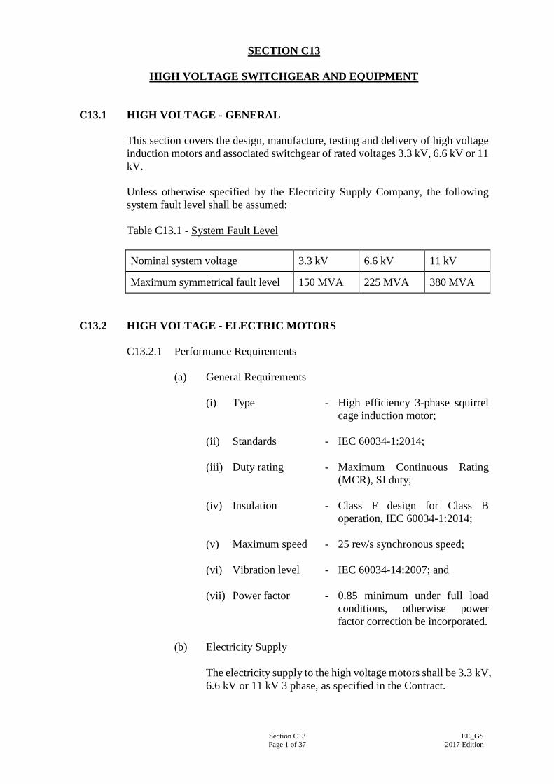
Section C13 Page 1 of 37
EE_GS 2017 Edition
SECTION C13
HIGH VOLTAGE SWITCHGEAR AND EQUIPMENT
C13.1 HIGH VOLTAGE - GENERAL
This section covers the design, manufacture, testing and delivery of high voltage induction motors and associated switchgear of rated voltages 3.3 kV, 6.6 kV or 11 kV. Unless otherwise specified by the Electricity Supply Company, the following system fault level shall be assumed: Table C13.1 - System Fault Level Nominal system voltage 3.3 kV 6.6 kV 11 kV
Maximum symmetrical fault level 150 MVA 225 MVA 380 MVA
C13.2 HIGH VOLTAGE - ELECTRIC MOTORS
C13.2.1 Performance Requirements
(a) General Requirements (i) Type - High efficiency 3-phase squirrel
cage induction motor;
(ii) Standards - IEC 60034-1:2014;
(iii) Duty rating - Maximum Continuous Rating (MCR), SI duty;
(iv) Insulation - Class F design for Class B operation, IEC 60034-1:2014;
(v) Maximum speed - 25 rev/s synchronous speed;
(vi) Vibration level - IEC 60034-14:2007; and
(vii) Power factor - 0.85 minimum under full load conditions, otherwise power factor correction be incorporated.
(b) Electricity Supply
The electricity supply to the high voltage motors shall be 3.3 kV, 6.6 kV or 11 kV 3 phase, as specified in the Contract.
Section C13 Page 2 of 37
EE_GS 2017 Edition
(c) Starting Performance
Unless otherwise specified, the motor shall be provided with auto-transformer starter to limit the starting current to not exceeding 2.5 times of full load current. The motor shall be designed to permit not less than three starts per hour equally spaced during normal running conditions. The motor shall also be suitable for two starts in succession followed by a 30 minutes interval before attempting another starting sequence. The minimum voltage at motor windings at starting shall be 50% nominal for motor with auto-transformer starter. The starting (run-up) torque characteristics of motor at minimum voltage shall be adequate for driving the load to full running speed under the most arduous conditions specified. The accelerating torque at any speed up to the peak torque point shall not be less than 10% of the motor rated full load torque. Motor with auto-transformer starting shall be with 50% rated voltage across its winding and without changing to its final connection, and shall run to at least 90% of its synchronous speed within 10 seconds.
(d) Power Rating
Motors shall be capable of operating continuously at any voltage in the range 90-110% of rated voltage and shall have power output of not less than 120% of the maximum power absorbed by the driven machines.
(e) Transient Recovery
Motors shall be capable of recovering normal operation in the event of a system disturbance causing temporary loss of supply voltage for periods of up to 0.2 seconds (fault clearance-time) followed by a sudden restoration to 80% rated voltage. At this voltage the motors shall then be capable of accelerating to ultimate recovery under the most arduous load conditions.
C13.2.2 Enclosure
For open type motor drive, the enclosure shall have the degree of protection of minimum IP44 unless otherwise specified. Dimensions and frame number of motors shall comply with IEC 60072-1:1991 and IEC 60072-2:1990. The motor frame shall be designed to facilitate easy removal of rotor assembly and to permit access from both motor ends for cleaning and rewinding of the stator winding and replacement of the complete stator
Section C13 Page 3 of 37
EE_GS 2017 Edition
core assembly. The motor shall be provided with suitable arrangement to facilitate lifting and handling during erection and overhaul.
C13.2.3 Thermal Insulation & Characteristics
The motor windings and accessories shall be designed for Class F insulation with Class B maximum temperature limit to IEC 60034-1:2007. Natural rubber insulated cables shall not be used between the stator windings and motor terminals.
C13.2.4 Motor Stators & Windings
The motor winding insulation shall withstand voltage stress caused by switching of motor starter using SF6 circuit breaker, vacuum circuit breaker or vacuum contactor. Motors shall be designed to permit high voltage tests in accordance with IEC 60034-1:2007 to be conducted after erection on site. End windings shall be rigidly braced to prevent their movement at the specified service duty. The insulation system of stator windings shall be of the resin-rich type or the vacuum pressure impregnated type. Windings shall be given a surface treatment where necessary to prevent deterioration resulting from adverse environmental conditions and for corona shield. Winding coils shall be of the pre-formed type. Random-wound type windings and hair-pin type windings are not acceptable. Stator slots shall be of the open type to facilitate easy insertion of replacement windings.
C13.2.5 Rotor
Unless otherwise specified, the rotor shall have cage type copper/copper alloy winding. The limits of vibration shall comply with IEC 60034-14:2007. The rotor shall be dynamically balanced at its rated speed or a speed not less than 600 rpm to confirm that vibration levels are within the specified limit. Means for fixing balancing weights in-situ shall be provided at both ends of the rotor without the need to dismantle the motor for balancing on site. For motors of 750 kW rating and above or where the induced shaft voltage exceeds 0.15 V, an insulated bearing arrangement shall be provided. Where such provision is made, all motor bearings shall be
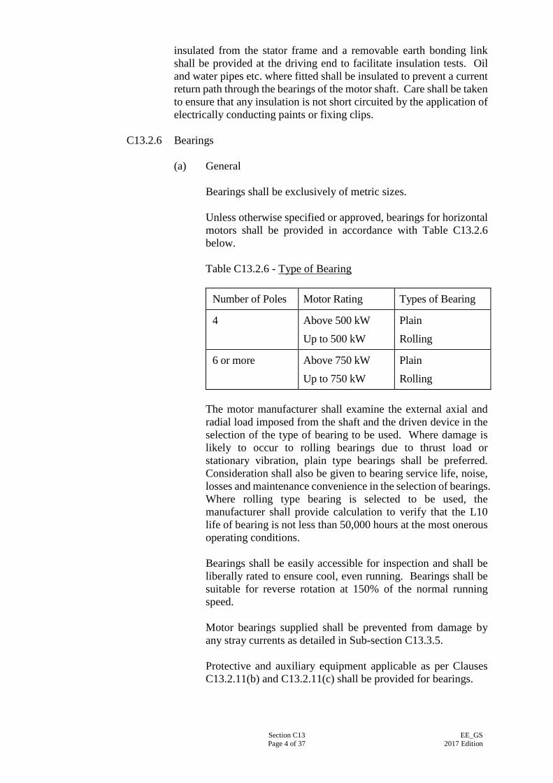
Section C13 Page 4 of 37
EE_GS 2017 Edition
insulated from the stator frame and a removable earth bonding link shall be provided at the driving end to facilitate insulation tests. Oil and water pipes etc. where fitted shall be insulated to prevent a current return path through the bearings of the motor shaft. Care shall be taken to ensure that any insulation is not short circuited by the application of electrically conducting paints or fixing clips.
C13.2.6 Bearings
(a) General
Bearings shall be exclusively of metric sizes. Unless otherwise specified or approved, bearings for horizontal motors shall be provided in accordance with Table C13.2.6 below. Table C13.2.6 - Type of Bearing
Number of Poles Motor Rating Types of Bearing
4 Above 500 kW
Up to 500 kW
Plain
Rolling
6 or more Above 750 kW
Up to 750 kW
Plain
Rolling The motor manufacturer shall examine the external axial and radial load imposed from the shaft and the driven device in the selection of the type of bearing to be used. Where damage is likely to occur to rolling bearings due to thrust load or stationary vibration, plain type bearings shall be preferred. Consideration shall also be given to bearing service life, noise, losses and maintenance convenience in the selection of bearings. Where rolling type bearing is selected to be used, the manufacturer shall provide calculation to verify that the L10 life of bearing is not less than 50,000 hours at the most onerous operating conditions. Bearings shall be easily accessible for inspection and shall be liberally rated to ensure cool, even running. Bearings shall be suitable for reverse rotation at 150% of the normal running speed. Motor bearings supplied shall be prevented from damage by any stray currents as detailed in Sub-section C13.3.5. Protective and auxiliary equipment applicable as per Clauses C13.2.11(b) and C13.2.11(c) shall be provided for bearings.

Section C13 Page 5 of 37
EE_GS 2017 Edition
(b) Plain Type Bearings
Plain type bearings shall be self-lubricated. The lubrication oil shall be water-cooled unless otherwise specified. The cooler shall be such as to avoid any electrolytic action or corrosion. Bearings shall be designed to exclude the ingress of dust and water and adequately sealed to prevent leakage of oil. The water pipes shall not run over or adjacent to the HV terminal boxes and shall not impede access to the bearing for inspection. The initial filling of bearing lubricating oil shall be supplied and delivered in an oil drum. Bearings shall be provided with a filling hole, an air breather, an accessible drain plug and a clearly visible oil level indicator to show oil levels during running and at standstill. Sight level indicators of the type fitted externally to the bearing shall be designed to prevent rotation about the gland connection. Besides the normal running operation, the lubrication shall also be adequate during starting and running down periods. The bearing design shall avoid oil being drawn into the winding through the shaft by centrifugal force or the effect of ventilation fan. The bearing mounting bracket assembly shall be capable of completely detached from the stator, viz. no welding to the stator frame shall be permitted. Bearing pads shall be self aligning in design, and shall not require any jacking screws for adjustment.
(c) Rolling Type Bearings
Rolling type bearings shall be adequately lubricated by grease and sealed against leakage of lubricant along the shaft. Construction shall be such that bearings can be dismantled and reassembled without risk of damage. The bearing assembly shall be designed to prevent the entry of dust or water. It shall be provided with a separate grease nipple to serve each lubricating point and a grease relief device such that when the motor runs at its rated speed any surplus grease is ejected out of the bearing casing to a separate container. Housings for ball/roller bearings shall be packed with approved lithium-based grease at the time of assembly. The required re-lubrication interval shall be more than 4,000 hours. Grease nipples, oil cups and dip sticks shall be readily accessible without removal of guarding. Where necessary for
Section C13 Page 6 of 37
EE_GS 2017 Edition
accessibility, nipples shall be remotely mounted at a point as near as is practicable to the lubrication point.
C13.2.7 Motor Foundation
A motor bedplate/foundation block shall be provided unless the motor is to be mounted on the soleplate of the compressor.
C13.2.8 Provision for Cabling and Termination
(a) Cabling Provision at Bedplates
Provision shall be made in the steel bedplate where necessary to facilitate straight run of cable to the bottom of the motor cable terminal box.
(b) Cabling Provision at Cable Boxes
Unless otherwise specified or approved, the cable terminal box for the motor shall be positioned at the side of the motor. Cable entry shall be from below for all box types unless otherwise specified. An earthing terminal with the same current carrying capacity as the line terminals with the minimum size suitable for 25 x 6 mm copper strip shall be provided. A tapped hole with screw external to the cable box would be acceptable. Permanent terminal marking and direction of rotation in accordance with IEC 60034-8:2014 shall be provided in the cable boxes.
(c) Cabling Provision at Motor Casing
The terminal leads from cable box terminals or connectors to the windings for a distance of 150 mm beyond their point of entry into the motor frame, shall be adequately braced to withstand the forces produced by maximum fault current. The phase windings shall be accessible for testing. For this purpose, neutral leads shall be brought out to a separate star-point terminal box and shorted with an insulated copper bar of cross-sectional area not less than the conductor of the terminal lead. Studs shall be so fixed as to prevent the terminal leads from turning when the nuts are tightened down. Means shall be provided to prevent slackening of cable connections due to vibration.
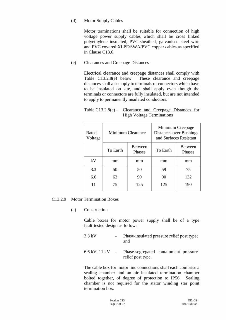
Section C13 Page 7 of 37
EE_GS 2017 Edition
(d) Motor Supply Cables
Motor terminations shall be suitable for connection of high voltage power supply cables which shall be cross linked polyethylene insulated, PVC-sheathed, galvanised steel wire and PVC covered XLPE/SWA/PVC copper cables as specified in Clause C13.6.
(e) Clearances and Creepage Distances
Electrical clearance and creepage distances shall comply with Table C13.2.8(e) below. These clearance and creepage distances shall also apply to terminals or connectors which have to be insulated on site, and shall apply even though the terminals or connectors are fully insulated, but are not intended to apply to permanently insulated conductors. Table C13.2.8(e) - Clearance and Creepage Distances for
High Voltage Terminations
Rated Voltage
Minimum Clearance Minimum Creepage
Distances over Bushings and Surfaces Resistant
To Earth Between Phases To Earth
Between Phases
kV mm mm mm mm
3.3
6.6
11
50
63
75
50
90
125
59
90
125
75
132
190
C13.2.9 Motor Termination Boxes
(a) Construction
Cable boxes for motor power supply shall be of a type fault-tested design as follows: 3.3 kV - Phase-insulated pressure relief post type;
and
6.6 kV, 11 kV - Phase-segregated containment pressure relief post type.
The cable box for motor line connections shall each comprise a sealing chamber and an air insulated termination chamber bolted together, of degree of protection to IP56. Sealing chamber is not required for the stator winding star point termination box.
Section C13 Page 8 of 37
EE_GS 2017 Edition
Termination boxes shall be fabricated from mild steel of a minimum of 6 mm thickness. Cast iron boxes shall not be accepted. The termination chamber shall be bolted to the motor casing such that its sides are vertical, with high tensile steel studs and nuts. The cable sealing chamber shall be fixed to the bottom of the termination chamber by means of high tensile steel bolts or studs and nuts. The cable sealing chamber for XLPE cable shall be of the dry type suitable for cable termination in heat shrinkable sleeving. Sealing chamber shall be fitted with a horizontal gland plate suitable for bottom cable entry. The termination chamber shall have an insulated assembly and be fitted with 3 stud terminals in insulating mouldings of epoxy resin, glass fibre, polyester or approved similar material. Porcelain insulators shall not be used. Cable-coupler type terminals shall not be acceptable. Front access detachable cover plates shall be fixed by studs and nuts. Separate plates shall be supplied for sealing and termination chambers. Joints shall be machined flat and fitted with neoprene rubber gaskets.
(b) Termination Box Auxiliaries
Brass cable glands shall be provided for motor supply cables. Cable lugs shall be supplied for the motor supply cable. Unless special lugs are used in the short circuit type test, cable lug shall be of the compression type manufactured from tin-plated seamless copper tubing with single bolt palm terminal. The cable lug shall be type-tested to IEC 61238-1:2003.
C13.2.10 Markings and Data Plates
An instruction and a data plate, of stainless steel, brass or other approved non-tarnishing metal shall be provided. The instruction plate shall give the connections and phase rotation for the required direction of rotation. The required direction of rotation shall be marked on the motor. The data plate shall be stamped with the information required by IEC 60034-1:2007. Data plates on which the above required information is only painted will not be accepted. The motor serial number shall be stamped with metal dies on the driving end shaft face of the motor in addition to being stamped on the stator.
Section C13 Page 9 of 37
EE_GS 2017 Edition
C13.2.11 Temperature Detectors for Motor Protection
(a) Embedded Temperature Detectors (ETD)
Unless otherwise specified, embedded temperature detectors of linear characteristics, e.g. thermocouple or resistance thermometer, and complete with monitoring unit shall be provided to offer protection against over-heating on load and stalling of the motor. Resistance temperature detector (RTD) shall comply with IEC 60751:2008. At least two detectors of the same characteristics suitably embedded in the stator shall be installed, positioned at points at which the highest temperatures are likely to occur, e.g. one detector between coil sides within the slots, one detector under the coils at the bottom of the slots and one detector between the coils and slot wedges. Detector leads shall be wired to an auxiliary cable box such that any ETD may be isolated for testing. The ETD monitoring unit for each motor shall have the following features: (i) Alarm contacts to operate at a temperature of 120ºC
which is adjustable for individual detecting elements; (ii) Trip contacts to operate at a temperature of 140ºC which
is adjustable for individual detecting elements; and (iii) A common digital temperature gauge and selection
buttons for reading the winding temperatures of the individual detecting elements.
(b) Temperature Detectors for Bearings
A temperature detector shall be installed for each bearing for high temperature alarm and trip operation. Unless recommended otherwise by the motor manufacturer, alarms detectors shall operate 10°C lower than the trip detectors. Insulated thermometer pockets shall be provided to enable easy insertion or removal of a temperature detector. Dial type thermometers or digital indicators, with independently adjustable alarm and trip contacts, shall be provided at the motor control switchboard to monitor the bearing temperatures. Contacts shall be arranged to close for alarm indication or tripping and shall be so arranged that the operation of the alarm or tripping may be checked manually.
Section C13 Page 10 of 37
EE_GS 2017 Edition
(c) Bearing Coolant Failure Detector
Where water cooled bearings are used a flow failure detector shall be provided. Suitable timers and relays shall be provided to obviate any false alarm during the starting up of the motor set or on flow surges.
C13.3 HIGH VOLTAGE - MOTOR CONTROL SWITCHBOARDS
C13.3.1 General Requirements
(a) The motor control switchboards shall be of the single busbar, indoor air-insulated, metalclad type formed into complete switchboards. The high voltage switchgear and switchboards shall comply with IEC 62271-100:2012 and IEC 62271-200:2011 respectively.
(b) The power to the high voltage motors shall be distributed from
the high voltage motor control switchboards through the motor starters incorporated in the switchboards. The control switchboards shall contain a motor starter for each motor set.
(c) The switchboards shall, but not be limited to, include the
following equipment:
(i) Incoming circuit breaker;
(ii) Motor starter;
(iii) Overcurrent and earth leakage protective relays and devices;
(iv) Motor temperature monitoring unit;
(v) Motor bearing temperature gauges;
(vi) Emergency stop button;
(vii) Local controls for ancillary equipment;
(viii) Sufficient terminals and cable glands for external cable connections;
(ix) Anti-condensation heater and associated thermostat;
(x) Isolators, fuses and other wiring ancillaries; and
(xi) Power factor correction capacitors and controlgear. (d) Type test certificates shall be available for each rating of circuit
breaker and switchboard to be supplied. The results of all type tests shall be recorded in type test reports containing sufficient data to prove compliance with the Specification. Type test certificates shall be issued preferably by the Association of Short-circuit Testing Authorities (ASTA) or N.V. tot Keuring

Section C13 Page 11 of 37
EE_GS 2017 Edition
van Elektrotechnische Materialen (KEMA). Test certificates issued by other organisations will only be accepted if the testing authority is established as being of equal standard as ASTA or KEMA.
(e) General Design Information
Table C13.3.1(e) - General design information Rated operational voltage 3.3 kV, 6.6 kV or 11 kV as
specified, 3-phase
Earthing of system Solid
System frequency 50 Hz
Installation type Indoor
Power supply for circuit breaker Operation, controls and protection
110 V dc ± 15%
Power supply for auxiliary Equipment
220 V ac ± 10% 1-phase 50 Hz
Degree of protection IP31
Insulation class Class B (f) Standards
The switchgear and cubicles for high voltage switchboard shall comply, in particular, with the following Standards where appropriate: Table C13.3.1(f) - Standards
IEC 60269-1:2014 Low–voltage fuses – Part 1: General requirements
IEC 60051:1997 Direct acting indicating electrical measuring instruments and their accessories
IEC 60255-1:2009 Electrical protective relays
IEC 60282-1:2014 Fuses for voltages exceeding 1,000 V AC
IEC 61869-2:2012 Current transformers
IEC 61869-3:2011 & IEC 61869-5:2011
Voltage transformers
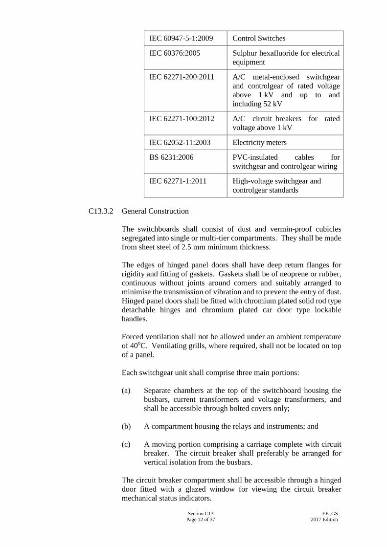
Section C13 Page 12 of 37
EE_GS 2017 Edition
IEC 60947-5-1:2009 Control Switches
IEC 60376:2005 Sulphur hexafluoride for electrical equipment
IEC 62271-200:2011 A/C metal-enclosed switchgear and controlgear of rated voltage above 1 kV and up to and including 52 kV
IEC 62271-100:2012 A/C circuit breakers for rated voltage above 1 kV
IEC 62052-11:2003 Electricity meters
BS 6231:2006 PVC-insulated cables for switchgear and controlgear wiring
IEC 62271-1:2011 High-voltage switchgear and controlgear standards
C13.3.2 General Construction
The switchboards shall consist of dust and vermin-proof cubicles segregated into single or multi-tier compartments. They shall be made from sheet steel of 2.5 mm minimum thickness. The edges of hinged panel doors shall have deep return flanges for rigidity and fitting of gaskets. Gaskets shall be of neoprene or rubber, continuous without joints around corners and suitably arranged to minimise the transmission of vibration and to prevent the entry of dust. Hinged panel doors shall be fitted with chromium plated solid rod type detachable hinges and chromium plated car door type lockable handles. Forced ventilation shall not be allowed under an ambient temperature of 40oC. Ventilating grills, where required, shall not be located on top of a panel. Each switchgear unit shall comprise three main portions: (a) Separate chambers at the top of the switchboard housing the
busbars, current transformers and voltage transformers, and shall be accessible through bolted covers only;
(b) A compartment housing the relays and instruments; and (c) A moving portion comprising a carriage complete with circuit
breaker. The circuit breaker shall preferably be arranged for vertical isolation from the busbars.
The circuit breaker compartment shall be accessible through a hinged door fitted with a glazed window for viewing the circuit breaker mechanical status indicators.
Section C13 Page 13 of 37
EE_GS 2017 Edition
The relay and instrument compartment shall be located at the front of each switchgear unit and shall be provided with a hinged door for access to the internal wiring and terminals. Moulded gaskets of non-aging material shall be used to provide close sealing. The height of the instrument panel above floor level shall not exceed 2,400 mm. All panels constituting a complete switchboard shall be of equal height. Bolted-on rear and top covers shall be designed to gain access to individual circuits without exposing other circuits which may be alive. Switchboards shall not be located across floor expansion joints. Before steelworks is painted, it shall be treated and degreased by an approved method such as grit blasting to ISO 8501-1:2007 or chemical pickling and an approved anti-rusting priming coat applied. The panels shall be externally finished in semi-gloss stoved enamel or cellulose to a colour to be approved by the Supervising Officer.
C13.3.3 Primary Busbars and Connections
Primary busbars and connections between the several pieces of apparatus forming the equipment of a switchboard shall be of high conductivity copper to BS EN 13601:2013. Construction, marking and arrangement of busbars, connections and auxiliary wiring shall be to IEC 62271-200:2011 and BS 159:2006. Primary busbars shall be contained in a separate compartments within the switchboard and access shall be possible only by means of bolted-on sheet steel covers which shall clearly be marked 'BUSBARS'. Busbars and busbar connections shall not be exposed when covers and doors are opened for access to the remainder of the switchgear. Busbars shall be readily extensible. Each phase conductor of the primary busbars including all through joints and tapping connections shall, in addition to being spaced at such intervals as to give the necessary air clearance for the voltage rating, shall be epoxy encapsulated solid copper bars. Joints shall be insulated with moulded removable insulated covers. Taping shall not be accepted. Primary busbars, connections and their supports shall be capable of carrying the short-time current associated with their short-circuit ratings for a period of 3 seconds. Where busbar supports use insulation of moulded or resin bonded material, it shall have a durable anti-hygroscopic surface finish with high anti-tracking properties. The connections from busbars in individual units shall have a continuous current rating of not less than that of the equipment comprising the unit.
Section C13 Page 14 of 37
EE_GS 2017 Edition
At all points where connections or joints occur, the busbars and connecting pieces shall be tinned or silver-plated. The resistance of any length of conductor containing a joint shall not be greater than that of an equal length without a joint. Jointing of sections of busbars shall be done by mechanical means. Soldered, braced, welded or riveted joints shall not be used in busbars. Jointing faces of copper conductors shall be tinned or silver plated, or applied with other approved treatment to maintain effective conductivity of the joint. All necessary busbar jointing bolts, nuts, and fixing accessories shall be provided. The recommended torque for tightening the bolts shall be stated in the maintenance manual. Primary busbars and connections shall be clearly marked and shall be displayed for standard phase sequence in accordance with the cable colour coding system, i.e. L1, L2 and L3, counting from front to rear, top to bottom, or left to right as viewed from the switching device operating mechanism side to IEC 62271-100:2012 or IEC 62271-200:2011.
C13.3.4 Circuit Breakers
(a) General Unless otherwise specified, the 11 kV circuit breaker units shall be of the vacuum type complying with IEC 62271-100:2012, and the 3.3 kV or 6.6 kV circuit breaker units shall be of the vacuum type or the sulphur hexafluoride (SF6) type complying with IEC 62271-100:2012. They shall be of a design with vertical isolation, horizontal withdrawal facilities. The moving portion of each circuit breaker unit shall consist of a three-pole circuit breaker with operating mechanism, primary and secondary disconnecting devices, auxiliary switches, position indicators and the necessary control wiring all mounted on a substantial steel framework. The framework and all metal part of the moving portion apart from current carrying parts, shall be solidly earthed via the fixed portion. The earthing of the moving portion shall be to the approval of the Supervising Officer. Means of registration shall be provided so that circuit breakers may be readily placed and secured in the correct position in the fixed portion. Circuit breakers of the same current and voltage rating shall be fully interchangeable with one another. Means shall be provided to prevent circuit breakers from being placed into fixed housings of different ratings. This device shall also prevent damage to isolating and other contacts. Each circuit breaker shall have remote control for opening and closing by authorised personnel inside the main switch room to
Section C13 Page 15 of 37
EE_GS 2017 Edition
enhance operation safety. The open switch and close switch of each circuit breaker shall be housed in a lockable box which is located near the door in the main switch room. The switches shall be labelled to identify the circuit breakers under control.
(b) Vacuum Circuit Breakers
For vacuum circuit breakers, means of confirming the validity of vacuum by the occurrence of flash-over when a voltage is applied between the vacuum interrupter contacts shall be included in the maintenance tools. Vacuum leakage shall be monitored to initiate an alarm and it shall not be possible to close a circuit breaker when vacuum leakage is serious enough to threaten safe operation of the switchgear. Vacuum circuit breakers for motor circuits shall incorporate surge suppressers to minimise the effects of switching transient voltage on the motor insulation.
(c) SF6 Circuit Breakers
A pressure switch shall be provided on the SF6 gas compartment to monitor the gas pressure. The system of gas monitoring shall be temperature compensated. Alarm and lockout feature shall be incorporated. Alarm signal shall be initiated and the breaker shall be inhibited from closing whenever the gas pressure drops below a preset level. The circuit breaker shall be prevented from operation. Means shall be provided in the gas compartment for the connection of service equipment and for the topping up of the gas. The circuit breaker shall be suitable to interrupt its rated normal current with SF6 gas at atmospheric pressure. The sealing of the gas compartment shall be designed so that there is no need for the SF6 gas to be replenished within reasonable periods. The gas leakage shall not exceed 1% per annum at site ambient temperature. An external contact indicator shall be provided to check the extent of contact wear. Means shall also be provided to allow access to the contacts of the interrupter units for necessary inspection and maintenance. All contact assemblies shall be replaceable. Safeguards shall be provided to prevent incorrect replacement of contacts. The designed electrical and mechanical life shall be at least 5,000 and 10,000 cycles respectively. The circuit breaker shall be capable of undergoing 40 cycles of fault breaking operations at 50% rated short-circuit breaking current or equivalent without any need of opening up the tank for inspection or contact replacement.
Section C13 Page 16 of 37
EE_GS 2017 Edition
Instructions for post-fault maintenance, gas top-up contact and seal replacement shall be clearly detailed in the manual.
(d) Operating Mechanisms
The circuit breaker operating mechanism shall be of the following types as specified: - Stored energy operation by means of a manually charged
spring with mechanical release; - Stored energy operation by means of a motor-charged
spring with manual and electrical release; and - Solenoid operated. The mechanism shall be of the trip free type so that the circuit breaker shall be free to open during the closing operation immediately its tripping device operates. The circuit breaker shall be capable of closing fully and latching against its rated making current. Spring operated mechanisms shall have the following additional measures: - If the circuit breaker is opened and the springs charged
the circuit breaker shall be able to be closed and then tripped;
- If the circuit breaker is closed and the springs charged
there shall be sufficient energy to trip, close and then trip the circuit breaker;
- Mechanical indication and an auxiliary switch for
remote electrical indication shall be provided to indicate the state of the springs;
- Motor charged mechanisms shall be provided with
means for charging the springs by hand, and also a shrouded push button for releasing the springs. An electrical release coil shall also be provided;
- Under normal operation, motor recharging of the
operating springs shall commence immediately and automatically upon completion of each circuit breaker closing operation. The time required for spring recharged shall not exceed 30 seconds; and
- It shall not be possible to close a circuit breaker, fitted
with a motor charged closing mechanism, whilst the spring is being charged. It shall be necessary for the
Section C13 Page 17 of 37
EE_GS 2017 Edition
spring to be fully charged and the associated charging mechanism fully prepared for closing before it can be released to close the circuit breaker.
All circuit breaker operating mechanism shall be fitted with an electrical shunt trip release coil and in addition a mechanical hand tripping device. The electrical tripping and closing devices shall be suitable for operation from a 110 V DC battery supply and but shall operate continuously with their coils at an ambient temperature of 40°C, over a voltage range as follow: - Closing solenoid : 80 to 120% of nominal
voltage;
- Spring charging motor: 80 to 110% of nominal voltage;
- Closing release coil: 80 to 110% of nominal voltage; and
- Shunt trip release coil: 50 to 120% of nominal voltage.
except that under battery boost charge conditions when they shall be capable of operating at rated output and 130% of nominal voltage for up to two hours. All operating coils for use on the DC supply shall be connected so that failure of insulation to earth does not cause the coil to become energised. Tripping and closing circuits shall be provided with a fuse in each pole on each unit and shall be independent of each other on all other circuits. Approved, positively driven mechanically operated indicating devices shall be provided to indicate whether a circuit breaker is in the open or closed service, isolated or earthed position.
(e) Isolating Devices
All circuit breakers shall be connected to their associated busbars and cables through isolating devices of an approved design to IEC 62271-100:2012 and IEC 62271-200:2011 which shall be arranged for operation whilst the main circuit is live but no current passing. The design shall be such that it is impossible for the isolating devices to be opened by forces due to current in the primary circuit and shall be interlocked with the circuit breaker so that it is impossible to make or break current with the isolating device.
Section C13 Page 18 of 37
EE_GS 2017 Edition
Attempted isolation shall not trip the circuit breaker. When isolation is effected by withdrawal of the circuit breaker, provision shall be made for positively locating the circuit breaker in the service, isolated and, earthing positions. Stops shall be provided to prevent over-travel and each position shall be clearly indicated. Preferably a mechanical selector mechanism shall be utilised such that when a particular position is selected, it is impossible to locate the circuit breaker in any other position. Isolating devices shall incorporate self-aligning contacts, the fixed contact of which shall be such that access can readily be obtained for maintenance purposes.
(f) Overcurrent and Earth Fault Protection
All circuit breakers other than those used for controlling the incoming supply, shall have overcurrent tripping facilities to give time delay overload current protection and instantaneous short circuit interruption. The time-current characteristics shall be submitted for inspection. Shunt trip coils operated by power supply from the mains shall not be used. For circuit breakers controlling the incoming supply to the Switchboard, the circuit protection shall be provided by the following devices: - Overcurrent Protection Relay;
- Earth Fault Relay; and
- Shunt-Trip Release. It shall be operated by a DC supply of 110 V obtained from the secondary batteries complete with battery charger, etc. of suitable rating.
(g) Safety Shutters
Metal shutter shall be provided to completely shroud fixed isolating contacts of the circuit breaker busbar and feeder circuits. These shutters shall be opened and closed automatically by the movement of the circuit breaker carriage and shall prevent access to fixed isolating contacts when the circuit breaker is withdrawn. The shutters for fixed isolating contacts connected to busbars and cables shall have independent operating mechanisms. All shutters shall have painted labels indicating whether they are busbar or feeder shutters. To facilitate high voltage and current injection testing via isolating contacts, a device shall be provided for fixing, but not
Section C13 Page 19 of 37
EE_GS 2017 Edition
locking, shutters in the open position and for releasing them to the closed position. This device shall be arranged to be disengaged as soon as the circuit breaker is pushed into the service position to ensure that the automatic features of the shutters are restored. Self-aligning plug and socket isolating devices shall be provided for all auxiliary circuits. The position of these devices shall be such that individual circuits on different units are in the same relative physical positions.
(h) Interlocking Gear
Interlocks shall be of the mechanical or key operated type and shall be provided to prevent the following operations: (i) A moving portion from being withdrawn from or
inserted into the isolating contacts when the circuit breaker is closed;
(ii) The closing of the circuit breaker unless the movable
portion is correctly plugged in or isolated from the equipment;
(iii) The movable portion being withdrawn or replaced
unless the circuit breaker is isolated and in the appropriate position;
(iv) The movable portion being plugged in without the
circuit breaker tank in position; (v) The circuit breaker being closed in the 'SERVICE' or
'EARTH' location without completing the appropriate auxiliary circuits; and
(vi) To apply an earth to busbars until all circuit breakers
which can feed the busbars, are locked open. When key interlocking is employed, any attempt to remove the trapped key shall not cause closing or opening of the associated equipment. Where a circuit breaker is fitted with means for mechanical or electrical operation, interlocks shall be provided so that it is impossible for the mechanical and electrical devices to operate simultaneously. The earthing devices shall be provided with interlocks to ensure correct operation in conjunction with the associated circuit breaker.
Section C13 Page 20 of 37
EE_GS 2017 Edition
In the case of circuit breaker earthing, the electrical tripping of the circuit breaker shall be rendered inoperative during earthing operations both when closing and when closed in the earthed position. It shall not be possible to return to the service position and close the circuit breaker until the electrical tripping is again operative. A mechanical key interlocking system shall be provided whereby it is not possible to apply an earth to busbars until all circuit breakers which can feed the busbar are locked open. In addition it shall not be possible to earth busbars and cable circuit at the same time by means of the same circuit breaker. In addition to safety interlocking which is integral to a circuit breaker unit to prevent wrong or dangerous operation of the unit itself, further interlocking shall be provided. In general, interlocking shall be electrically isolating the closing contactor coil circuit of a circuit breaker being interrupted unless the necessary conditions for closure are met. The interlocking shall be designed on a system wide basis to ensure that subsequent operation of a non-interlocked circuit breaker does not result in a set of conditions that would contradict the original 'permission to close'.
(i) Interlocking Circuits
Where interlocking over a distance is required, two independent criteria shall be used, such as absence of a voltage and remote feeding circuit breaker open. Indication of the remote condition shall be by single purpose circuit, care being taken that the conductors used are adequately screened and shielded to minimise both transverse and longitudinal voltages resulting from electromagnetic induction and differences in earth potential. The cable containing cores for interlocking circuits shall be separate from all other multi-core cables. All interlocking circuits shall be of the 'go and return' design, and in no instance will interconnection of batteries in different locations be permitted. Where a circuit breaker is capable of manual operation in addition to electrical operation, except where such manual operation is possible only for maintenance purposes, key-operated interlocking shall additionally be provided, operative only in the instance of manual operation. Electrical interlocks on withdrawable equipment shall be arranged so that when withdrawn, the equipment operation will be independent of the remote interlocking contacts. In addition, the interlocks shall be such that, when the equipment is withdrawn, the interlocking of associated apparatus is correct,
Section C13 Page 21 of 37
EE_GS 2017 Edition
and operation of the equipment in the withdrawn position will have no effect.
(j) Locking Facilities
Locking facilities shall be provided so that the circuit breaker can be prevented from being closed when it is open and from being manually tripped when it is closed. These facilities shall not require the fitting of any loose components prior to the insertion of the single padlock required. It shall not be possible, without the aid of tools, to gain access to the tripping toggle or any part of the mechanisms which would permit defeat of the locking of the manual trip. It shall not be possible to lock mechanically the trip mechanisms so as to render inoperative the electrical tripping. In addition, the following padlocking facilities shall also be included: (i) Selector mechanisms on circuit breaker isolated and
service positions; and (ii) Safety shutters on primary contact isolating orifices in
closed position. All switchboard access doors, other than those which are interlocked with a switching device, shall be provided with an integral type locking facility.
C13.3.5 Earthing and Earthing Devices
All metal parts other than those forming part of an electrical circuit shall be connected in an approved manner to a hard drawn, high conductivity copper earth busbar which shall run the full length of, and be bolted to, the main frame of the switchboard. At the position where joints occur, the earth busbar shall be tinned. The earth busbar shall be rated to carry currents equal in magnitude and duration to that associated with the short circuit rating of the equipment. The design and construction of the equipment shall be such that all metal parts, other than the current carrying parts, or the withdrawal equipment are earthed before the primary connections are made. Metal cases supports and bases of all instruments, relays or other associated components mounted on the switchgear shall be connected to the earth busbar by conductors of not less than 2.5 mm2 cross-sectional area. When components are provided for mounting separately each shall be provided with an earthing terminal of not less than 30 mm2 cross sectional area.

Section C13 Page 22 of 37
EE_GS 2017 Edition
Earthing devices shall be provided on all circuit breaker units whereby the circuit can be earthed. With the circuit earthed, shutters over unearthed fixed main isolating contacts shall be closed. Busbar earthing facilities shall be provided on selected circuits of each separate switchboard, these circuits shall be agreed with the Supervising Officer. Circuit and busbar earthing shall be of the transfer circuit breaker arrangement and it is preferred that the facilities shall be integral in the design and construction of the switchgear. Earthing devices for fitting to the circuit breakers are acceptable but they shall be supplied in a separate container together with a set of instructions for fitting and operating the equipment. Designs effecting earthing by means of a separate fault-making switch are not acceptable. Feeder and busbar earthing devices shall have a short circuit rating equal to that of their associated circuit breaker. Padlocking facilities shall be provided for the purpose of preventing inadvertent earthing. Labelling shall be provided to show whether the equipment is prepared for 'SERVICE', 'BUSBAR EARTH' or 'CIRCUIT EARTH'. Such indication shall be visible from the front of the equipment at all times. Duplicate labels in Chinese and English shall be provided.
C13.3.6 Testing Facilities
All circuit breaker units shall be provided with facilities to enable applied high voltage tests to be carried out. Provision shall also be made for temporarily completing the auxiliary circuits when the circuit breaker is isolated and if applicable, withdrawn to enable the functioning of the circuit breaker to be tested. When current transformers and protective relays are fitted, facilities shall be provided for primary and secondary injection tests to be carried out. These facilities shall preferably be such that wires and connections need not be disconnected for the tests to be carried out.
C13.3.7 Mechanical Indication Indication shall be provided to clearly indicate whether a circuit breaker is in the open or closed service, isolated or earthed position. Positively driven mechanical indicating devices shall be provided on all equipment to indicate the following where applicable: (a) Circuit breaker 'OPEN' or 'CLOSED'; and

Section C13 Page 23 of 37
EE_GS 2017 Edition
(b) Circuit breaker 'SPRING CHARGED' or 'SPRING FREE'
C13.3.8 Auxiliary Switches Auxiliary switches of the double-break type and positively driven in both directions shall be provided on all circuit breakers and isolators for indication, control and interlocking. Auxiliary switches shall be strong, have a positive wiping action when closing and shall be mounted in an accessible position clear of operating mechanisms. They shall be designed to make, break and carry, without undue heating, the current of their associated circuit. Auxiliary switches shall be rated for 10 A operational current, and shall be capable of breaking at least 2 A at 110 V DC. No less than eight spare auxiliary switches shall be provided with each circuit breaker and no less than four with each isolator. Each spare contact shall be readily changeable from normally open to normally closed and vice versa. All auxiliary switches shall be wired up (via secondary disconnecting devices if on withdrawable equipment) to a terminal board on the front of the fixed portion, arranged in the same sequence for each individual unit of the same type.
C13.3.9 Anti-Condensation Heaters Anti-condensation heaters of an approved type shall be provided inside each cubicle. They shall be thermostatically controlled and shall operate at black heat and shall be shrouded and located so as not to cause injury to personnel or damage to equipment. The heaters shall be controlled from a double-pole miniature circuit breaker, with a lamp to indicate 'cubicle heaters on'. The circuit breaker and indicating lamp shall be mounted externally at one end of the switchboard. The heaters shall operate from 220 V 50 Hz single phase AC supply.
C13.3.10 Current Transformers Current transformers shall comply with IEC 60044-1:2003 and shall be suitable for the operation of protective gear, instruments and/or metering equipment. Current transformers shall be of the epoxy resin encapsulated type and shall have necessary output to operate the connected protective devices or instruments. The primary windings shall have a short time current rating not less than that specified for the associated circuit breaker. The rated secondary current shall be 1 A or 5 A. Protection current transformers shall be of Class 10P accuracy or better.
Section C13 Page 24 of 37
EE_GS 2017 Edition
The product of rated accuracy limit factor and rated output of the protection current transformer shall not be less than 10 times the rated burden of the trip circuit including the relays, connection leads and overcurrent release where applicable. Measurement current transformers shall be suitably rated and have accuracy Class of 3 for use with ammeters, and Class 1 for other types of meters. The polarity of the primary and secondary windings of each current transformer shall be clearly indicated and in addition labels shall be fitted in a readily accessible position to indicate the ratio, class and duty of each transformer. The current transformer particulars as specified in IEC 61869-2:2012 shall be given on an accessible plate mounted external to the current transformer. All connections from secondary windings shall be brought out and taken by means of separate insulated leads to a terminal board mounted in an accessible position. Where multi-ratio secondary windings are required, a label shall be provided at the secondary terminal board clearly indicating the connections required for each ratio. Current transformers for indication or metering shall have their secondary windings earthed at the switchgear. The secondary windings of current transformer for protection shall be earthed at the panel which accommodates the associated relay. The earth connection shall be made via a removable link. Each current transformer shall have a certified maximum rating of at least 1.2 times the rated current.
C13.3.11 Voltage Transformers Voltage transformers shall comply with IEC 61869-3:2011 and IEC 61869-5:2011 and suitable for the operation of protective gear, voltage regulating equipment, instruments and/or metering. All voltage transformers shall be of the dry type with epoxy encapsulation. The rated output per phase at a power factor 0.8 lagging shall not be less than 100 VA. The rated voltage factor shall be 1.2. They shall have a measuring accuracy class of 0.5 and a protective accuracy class of 3P. Voltage transformers shall be capable of carrying continuously without injurious heating 50% burden above their rated burden. The rated primary voltage of voltage transformers shall be the appropriate nominal system voltage. Unless specified otherwise, voltage transformer primary windings shall be connected to the circuit side of the current transformers remote from the busbars so as to be included in the protected zone of the associated feeder. The primary of a single phase voltage transformer shall be connected
Section C13 Page 25 of 37
EE_GS 2017 Edition
across L1 and L2 or A and B phases, unless otherwise approved. L1 and L2 phases shall be used in a synchronising scheme, unless otherwise approved. Voltage transformers shall be capable of being connected and disconnected from the equipment whilst in service. Facilities for padlocking in the service position shall be provided. Where isolating is carried out by withdrawal, a set of shutters, capable of being padlocked, shall be provided to cover the stationary isolating contacts. The shutters shall operate automatically by positive driven drive actuated by movement of the voltage transformer assembly. The primary windings shall preferably be connected via renewable fuses with current limiting features which shall be readily accessible with the circuit alive and the secondary windings through fuses and links, labelled to indicate their function and phase colour, to the appropriate circuits. For single phase voltage transformers, both ends of each secondary-winding shall be brought out to insulated links. For three phase voltage transformers, each phase end shall be brought out to fuses, and the neutral of the secondary winding shall be brought out to insulated links. The fuses and links shall then be brought out to insulated terminals located in a terminal box. The primary and secondary fuses shall be capable of being removed and replaced when the circuit breaker is closed in the service position. Isolation of the primary fuses for this purpose shall be carried out, preferably by withdrawing the entire voltage transformer assembly. Additionally, it shall be possible to remove secondary fuses whilst the voltage transformer is padlocked in the service location. For single phase units, separate earth links for each secondary winding shall be provided. Each of the neutral leads shall be connected together at a single point and earthed as close as possible to the voltage transformer. Voltage transformer secondary windings shall be earthed at the switchgear through a link which can be removed for insulation testing. Voltage transformers having the neutral point of their higher voltage windings earthed, shall be designed so that saturation of the core and dangerous over-heating arising therefrom shall not occur when 1.73 times normal voltage is applied to each winding for a period of 15 minutes. Secondary circuits of voltage transformer shall not be parallel. The secondary voltage connections to metering circuits shall be broken automatically when the circuit breaker is opened.
Section C13 Page 26 of 37
EE_GS 2017 Edition
C13.3.12 Cables Boxes
Cable boxes shall be suitable for terminating the cables directly into the switchgear. The dimensions and terminal arrangements, together with details of air insulated heat-shrinkable elastomeric PCP cable termination, shall be submitted for approval by the Supervising Officer before manufacture. All cable boxes shall be suitable for use with air insulated heat-shrinkable elastomeric PCP cable termination and shall be designed with joint faces which will ensure leak-free operation and exclude the entry of air, dust or moisture. The internal surfaces of cable boxes shall be cleaned of all scale and rust and after cleaning and priming, shall be finished with a hard setting paint compatible with the filling medium. Where cable boxes are provided for three-core cables, the sweating sockets on the two outer phases shall be inclined towards the centre to minimise bending of the cable cores. Where there is more than one core per phase, the socket block shall be so designed as to minimise bending of the cable cores, and spacer clips shall be incorporated. All cable terminals shall be of adequate size to ensure no overheating takes place at rated current. The insulators and fittings shall be unaffected by atmospheric and climatic conditions, ozone, acids or alkalis, dust deposits or rapid temperature changes likely to arise when operating in the specified site conditions and shall be designed so as to facilitate cleaning.
C13.3.13 Protective Relays
Unless otherwise specified, Clause C5.26 shall apply.
C13.3.14 Control and Timer Relays
Control and timer relays shall be of the plug-in type, rack mounted, provided with cable connection terminal and anchored by quick fastening vibration-proof devices. Timer shall be of the solid-state type with proven reliability.
C13.3.15 Indicating Instruments
Unless otherwise specified, Clause C5.26 shall apply.
C13.3.16 Labels and Warning Notice
Laminated 'Traffolyte' or similar labels of ample size shall be provided for each of the units on the switchboards engraved in English and Chinese characters. Labels shall be fixed by screws on the non-detachable parts of the panel at a height of 1350 mm or above.
Section C13 Page 27 of 37
EE_GS 2017 Edition
During the progress of manufacture of the switchboard, a schedule of labels shall be submitted for approval by the Supervising Officer before engraving is carried out. 'Danger - H.V. Live Terminals/ 危險 – 高壓帶電電極' warning labels shall be attached to the access covers of the air insulated cable boxes, CT chambers and busbar, and shall be coloured red with white lettering in both English and Chinese characters. In addition to automatic screening shutters and barriers, warning labels shall also be provided for all live parts, such as test terminal blocks.
C13.3.17 Ancillary Equipment
Battery charger/batteries system shall be provided for the proper functions of the switchgear in the switchboard. The switchboard shall be supplied complete with one hydraulic operated handling device suitable for handling all sizes of air circuit breakers in the switchboard, and one set of portable earthing equipment for each main incoming air circuit breaker. Portable earthing leads will not be accepted as an alternative to the earthing equipment. The switchboard shall be supplied complete with all operating handles, jigs, etc. required for the normal charging, closing, opening, racking in and out operations of all circuit breakers of the switchboard and shall be properly fixed in a neat manner on a board with brass hooks inside the main switch room where the switchboard is installed. The switchboard shall be provided with two rubber mats of ribbed surface, complying with IEC 61111:2009, laid in front of and at the rear of the switchboard. The rubber mats shall be continuous sheets of 10 mm minimum thickness, each of the same length as the cubicle switchboard and a minimum width of not less than 1,000 mm or the width of the space between the front or back of the switchboard to the adjacent wall.
C13.3.18 Operation Diagram
For high voltage switchboards with interlocking facility, a brief operation instruction of the switchboards together with a detailed schematic wiring diagram, listing out all the relevant switching steps and interlocks for commissioning/decommissioning of part or whole of the high voltage switchboards shall be provided in a framed, transparent perspex sheet mounted adjacent to the switchboards.
C13.4 HIGH VOLTAGE - AUTO-TRANSFORMERS
C13.4.1 General
Section C13 Page 28 of 37
EE_GS 2017 Edition
The auto-transformers for the auto-transformer motor starters shall comply with the following specific requirements: (a) Type - Indoor and floor mounted type for no
breaking starting of squirrel cage 3-phase induction motor;
(b) Standard - IEC 60076:2015;
(c) System Voltage - 3.3 kV, 6.6 kV or 11 kV as specified;
(d) Frequency - 50 Hz;
(e) Connections - Auto-star for auto-transformer starting;
(f) Insulation Level - 45 kV peak impulse voltage for 1/50 microsecond;
(g) Cooling - Natural air cooled; and
(h) Tappings - Off load tap changers with 60%, 75% and 85% of the line voltage to limit the starting current to 2.5 times of full load current.
The auto-transformers shall be mounted on wheels to facilitate positioning and removal. The transformers shall be externally finished in semi-gloss stoved enamel or cellulose.
C13.4.2 Rating
The rating of the auto-transformer shall be designed to suit the starting duty of the motor. Motor starting time shall be taken as 10 seconds at 75% or higher taps and 15 seconds at 60% or lower taps unless otherwise specified in the Particular Specification.
C13.4.3 Insulation
(a) Insulation Medium
Unless otherwise specified, for 11 kV nominal voltage, oil-filled transformers are preferred. Epoxy resin encapsulated auto-transformers shall be preferred for nominal voltage up to 6.6 kV.
(b) Class
Oil immersed transformer windings shall be designed for Class E insulation for Class E operation. Epoxy resin encapsulated transformer windings and live parts in air shall be designed for Class F or Class B insulation for Class B operation.
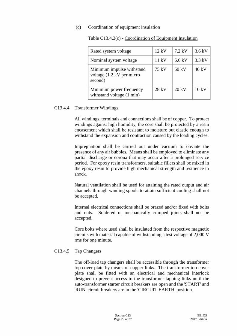
Section C13 Page 29 of 37
EE_GS 2017 Edition
(c) Coordination of equipment insulation
Table C13.4.3(c) - Coordination of Equipment Insulation Rated system voltage 12 kV 7.2 kV 3.6 kV
Nominal system voltage 11 kV 6.6 kV 3.3 kV
Minimum impulse withstand voltage (1.2 kV per micro- second)
75 kV 60 kV 40 kV
Minimum power frequency withstand voltage (1 min)
28 kV 20 kV 10 kV
C13.4.4 Transformer Windings
All windings, terminals and connections shall be of copper. To protect windings against high humidity, the core shall be protected by a resin encasement which shall be resistant to moisture but elastic enough to withstand the expansion and contraction caused by the loading cycles. Impregnation shall be carried out under vacuum to obviate the presence of any air bubbles. Means shall be employed to eliminate any partial discharge or corona that may occur after a prolonged service period. For epoxy resin transformers, suitable fillers shall be mixed in the epoxy resin to provide high mechanical strength and resilience to shock. Natural ventilation shall be used for attaining the rated output and air channels through winding spools to attain sufficient cooling shall not be accepted. Internal electrical connections shall be brazed and/or fixed with bolts and nuts. Soldered or mechanically crimped joints shall not be accepted. Core bolts where used shall be insulated from the respective magnetic circuits with material capable of withstanding a test voltage of 2,000 V rms for one minute.
C13.4.5 Tap Changers
The off-load tap changers shall be accessible through the transformer top cover plate by means of copper links. The transformer top cover plate shall be fitted with an electrical and mechanical interlock designed to prevent access to the transformer tapping links until the auto-transformer starter circuit breakers are open and the 'START' and 'RUN' circuit breakers are in the 'CIRCUIT EARTH' position.
Section C13 Page 30 of 37
EE_GS 2017 Edition
C13.4.6 Internal Earthing of Transformers
Metal parts of the transformer with the exception of individual core laminations, core bolts and associated individual clamping plates shall be maintained at some fixed potential. Where metal parts of the core are connected to earth this shall be done by way of accessible links to allow the insulation between core and earth to be tested. This insulation shall be able to withstand a test voltage of 2,000 V rms. The magnetic circuit shall be earthed to the clamping structure at one point only through a removable link placed in an accessible position beneath an inspection opening in the tank cover. The connection to the link shall be on the same side of the core as the main earth connection. Where coil clamping rings are of metal at earth potential, each ring shall be connected to the adjacent core clamping structure.
C13.4.7 Enclosure
(a) General
The enclosure shall be of rigid construction and shall not be damaged at short-circuit faults. Exterior corners and edges shall be rounded to give a smooth overall appearance. The design of the enclosure shall ensure adequate ventilation and air circulation without forced cooling or additional electric fans. The enclosure shall be designed so as to allow the complete auto transformer in the tank and filled with oil, to be lifted by crane or jacks, transported by road, rail or water, skidding in any direction on plates or rails without over-straining any joints and without causing subsequent leakage of oil. The tank or enclosure exterior shall be fitted with a M12 stud at the bottom of the unit suitable for termination of a copper earthing bar of 32 x 3 mm.
(b) Enclosures for Epoxy Resin Cast Auto-transformers - Additional Requirements Unless otherwise specified, a rectangular splash-proof enclosure of degree of protection to IEC 60529:2013/Corr 2:2015, IP32 shall be provided covering the entire unit. The enclosure shall be sheet steel of 2 mm minimum thickness and suitably braced to form a rigid structure. The enclosure shall be bolted to the transformer frame and shall be easily removable when required. Access panels and openings shall be provided to facilitate routine inspection and maintenance, and changing of tap position without the need for dismantling the enclosure completely.
Section C13 Page 31 of 37
EE_GS 2017 Edition
(c) Enclosure (Tank) for Oil-filled Auto-transformers
(i) General
A rectangular totally enclosed tank to IP65 shall be supplied covering the entire unit. Oil tank shall be fabricated from weldable structural steel to BS EN 10025:2004, BS EN 10029:2010 or products having equivalent functions or performance, with all welding to BS EN 1011-1:2009 or equivalent. Fabricated under bases shall be provided with skids and detachable rollers. The exterior of the tank shall be of plain sheet steel without stiffeners. Tank stiffeners shall be continuously welded. Wherever possible the transformer tank and its accessories shall be designed without pockets wherein gas may collect. All joints of the oil tank other than those which may have to be broken shall be welded. Caulking of defective welded joints will not be permitted. All joint faces shall be designed to prevent the ingress of water or leakage of oil with a minimum of gasket surface exposed to the action of oil or air. Unless otherwise approved, oil resisting synthetic rubber gaskets shall not be used, except where the synthetic rubber is used as a bonding medium for cork or similar material.
(ii) Pressure Relief Device
Each tank shall be fitted with an approved pressure relief device designed to protect the tank from damage and control the explosion of oil under internal fault conditions. The device shall operate at a static pressure of less than the hydraulic test pressure for transformer tank but not exceeding 70 kPa. Means shall be provided to prevent the ingress of moisture and dust. Unless otherwise approved the relief device shall be mounted on the main tank and, if on the cover, shall be fitted with a skirt projecting 25 mm inside the tank to prevent gas accumulation. If a diaphragm is used, it shall be of approved design and material and situated above the maximum oil level.
(iii) Tank Cover
Each tank cover shall be of adequate strength, and shall not distort when lifted. Inspection openings shall be provided as necessary for changing tap position. Each
Section C13 Page 32 of 37
EE_GS 2017 Edition
inspection opening shall not be less than 450 mm by 360 mm and shall not weigh more than 25 kg. The tank cover shall be provided with lifting welded eyes. The bolt holds in all cover plates shall be provided with washers which will prevent the collection of moisture in the bolt hole. The tank cover shall be fitted with pockets for a thermometer and for the bulbs of the winding or oil temperature indicators. Protection shall be provided where necessary for each capillary tube. The thermometer pocket shall be fitted with a captive screwed cap to prevent the ingress of water. The pockets shall be located in the position of maximum oil temperatures at full rated power and it shall be possible to remove the instrument bulbs without lowering the oil level in the tank.
(iv) Transformer Auxiliaries
Each transformer shall be fitted with: - An oil level indicator of prismatic glass visible
from ground level and indicating the oil levels over the range specified. The oil level indicator shall be marked to indicate the correct oil level with the oil at a temperature of 15ºC, 50ºC and 90ºC; and
- An oil seal silica gel breather or other approved
type device complete with dehydrating agent, indicator and sight glass. Breathers shall be at least one size larger than the size that would be fitted in temperate climate and shall be mounted approximately 1,000 mm above ground level.
(v) Transformer Oil
The transformer oil shall comply with IEC 60296:2012. The first filling of transformer oil shall be supplied with the Contract. All oil that may be used for works processing or testing shall be compatible with the oil to be used on site.
(vi) Valves and Flanges
All valves up to and including 100 mm shall be of gunmetal. Larger valves may be gunmetal or may have cast iron bodies with gunmetal fittings. They shall be of the full way type with internal screw and shall be opened by turning counter-clockwise when facing the handwheel. Butterfly type valves shall only be used for
Section C13 Page 33 of 37
EE_GS 2017 Edition
isolation of radiator. Means shall be provided for padlocking the valve in the open and closed positions. Every valve shall be provided with a mechanical indicator to show clearly the position of the valve. All valves shall be provided with flanges having machined faces. Each transformer shall be fitted with the following: - One 50 mm filter valve at the top and one 50 mm
combined filter and drain at the bottom of the tank mounted diagonally opposite to each other for connection to oil circulating equipment;
- A robust sampling device at the top and bottom
of the main tank. The sampling devices shall not be fitted on the filter valves specified above;
- A drain valve for oil tank; and - Flanged type air release plugs as necessary. All valves opening to atmosphere shall be fitted with blank flanges.
C13.4.8 Finishes
(a) Surface Preparation
Before untreated steelwork is painted it shall be thoroughly cleaned by an approved method such as grit blasting to the relevant parts of ISO 8501 series or chemical pickling and an approved anti-rusting priming coat applied. Treated steelwork shall be suitably cleaned and degreased.
(b) Painting - External Surfaces
Panel surfaces shall have not less than one primer coat, two stoved undercoats and two top stoved coats of paint. Undercoats shall be epoxy based and easily distinguishable in shade or colour from the priming and finishing coats. The two final coats shall have a total minimum dry film thickness of 0.075 mm with each coat separately stoved in an air-circulating oven. The final paint coating shall be of semi-matt finish and the colour shall be approved by the Supervising Officer. Oil tanks and other accessories shall be coated with air-drying paints by cold airless spray to a minimum total dry film
Section C13 Page 34 of 37
EE_GS 2017 Edition
thickness of 0.127 mm. Bright/gloss parts shall be protected with a coat of readily removable composition which shall be effective in preventing corrosion during transport and storage.
(c) Painting - Internal Surfaces
In oil tank, interior surfaces shall be painted in an identical manner to the external surface with air-drying oil and petrol-proof paint. The finishing colour of oil tank shall be red. For epoxy resin transformer enclosures, the interior surfaces shall be finished in white with anti-condensation paint.
C13.4.9 Rating Plates and Diagrams
The following plates shall be fixed to the transformer enclosure or tank at 1700 mm average height above ground level: (a) A rating plate bearing the data specified in IEC 60076:2015 and
the duty rating; (b) A diagram plate showing the internal connections and in
addition a plan view of the transformer giving the correct physical relationship of the terminals. The percentage tapping shall be indicated for each tap;
(c) For oil immersed transformers, a plate showing the location and
function of all valves and air release cocks or plugs. This plate shall also warn operators to refer to the Maintenance instructions before applying vacuum treatment; and
(d) Identification plates for the purpose of each removable
inspection cover e.g. tap changer access etc. The above plates shall be of stainless steel or brass. External plates and labels shall be fixed by phosphor bronze, stainless steel or brass screws with 3 mm thick fibre washers at the front and back of the fixing holes. Tapping holes in transformer tank walls for fixing plates will not be accepted.
C13.4.10 Cable Boxes
The auto-transformer cable boxes complete with cable glands shall be suitable for the termination of high voltage power cables. Cable boxes shall be air insulated and designed to suit the termination of high voltage cables. Cable boxes shall be designed to accommodate all cable joint fittings
Section C13 Page 35 of 37
EE_GS 2017 Edition
or sealing-ends required by the manufacturers of the cables, including stress cones or other approved means for grading the voltage stress on the terminal insulation of cables. Provision for earthing the body of each cable box shall be made. Cable boxes designed for three-core cable shall have seating sockets on the two outer phases inclined towards the centre to minimise bending of the cable cores. Where there is more than one core of cable per phase, the socket block shall be so designed as to minimise bending of the cable cores.
C13.5 HIGH VOLTAGE - POWER FACTOR CORRECTION CAPACITORS
The power factor correction capacitors for the high voltage chiller motors shall improve the overall power factor of the chiller motors to 0.95 lagging at rated output power. The kVAr rating of the capacitor shall not exceed 85% of the no load magnetising kVAr of the chiller motor. Specific requirements of the power factor correction capacitors shall be as follows: (a) Type - Low loss dielectric type, indoor and enclosed in
floor-mounted cubicles;
(b) Rated Capacity
- To suit the power factor to be improved;
(c) System voltage - 3.3 kV, 6.6 kV or 11 kV as specified;
(d) Frequency - 50 Hz;
(e) Connection - Delta-connected single-phase units;
(f) Insulation Level - 45 kV peak impulse voltage for 1/50 microseconds; and
(g) Protection - 3 line connected high voltage HBC fuses to IEC 60282-1:2014 with striker pin.
The output ratings of the power factor correction capacitor may require modification subject to the no-load magnetising kVAr rating of the high voltage motors to be driven. The power factor correction capacitors shall be provided with combined jacking and haulage lugs to facilitate positioning. The capacitors shall be externally finished where applicable in semi-gloss stoved enamel or cellulose. The power factor correction capacitors shall be protected by high voltage high breaking capacity fuses with striker pins to IEC 60282-1:2009. The striker pin shall be arranged to operate an auxiliary contact to trip the starter circuit breakers.
Section C13 Page 36 of 37
EE_GS 2017 Edition
The power factor correction capacitor cable box complete with cable glands shall be suitable for the termination of the high voltage power cables.
C13.6 HIGH VOLTAGE - POWER CABLES
C13.6.1 General
All high voltage power cables shall be insulated with cross-linked polyethylene. The 3.3 kV power cables shall comply with IEC 60502-1:2009 whereas 6.6 kV and up to 33 kV power cables shall comply with IEC 60502-2:2014. Where specified, cables shall be wire armoured and finished overall with a continuous outer sheathing of polyvinyl chloride (PVC). All cables shall be designed for operation on a system earthed either direct or through resistance or reactance at one or more neutral points. No straight through cable joints shall be installed without the approval of the Supervising Officer. For identification the rating of the cable shall be impressed into the outer insulation at regular intervals.
C13.6.2 Cross-Linked Polyethylene (XLPE) Cables
High voltage cross-linked polyethylene insulated (XLPE) cables shall be of the 1,900/3,300 V grade for 3.3 kV power cables, 3,800/6,600 V grade for 6.6 kV power cables and 6,350/11,000 V grade for 11 kV power cables. Multi-core cables shall comprise stranded annealed copper conductors. The insulation shall consist of cross-linked polyethylene applied by extrusion, bedded in a minimum of two layers of suitable tape. Armouring, where specified, shall comprise a single layer of galvanised steel wires or aluminium strip and the cable shall be served with an extruded layer of PVC. Single core cables shall comprise circular copper conductors and where armoured shall comprise non-magnetic aluminium wire or strip.
C13.6.3 Conductors
Copper conductors shall be stranded and shall consist of plain annealed copper. Before stranding, the conductors shall be approximately circular in section, smooth, uniform in quality, free from scale, inequalities, spills, splits and other defects. There shall be no joints in the wire except those made in the base rod or wire before final drawing. The term 'annealed' signifies that the wire before stranding is capable of at least 15 percent elongation without fracture, the test piece being
Section C13 Page 37 of 37
EE_GS 2017 Edition
not less than 150 mm and not more than 300 mm long. The stranded conductor shall be clean and reasonably uniform in size and shape and its surface shall be free from sharp edges. In the formation of shaped conductors containing less than 19 strands the same number of strands shall be used as for a circular conductor of equivalent area. For conductors having 19 strands or more the number of strands shall be the same as in a circular conductor of equivalent area, subject to a maximum permissible variation of plus or minus one strand. All the strands in any given shaped conductor shall be of the same nominal size.
C13.6.4 Cable Terminations
Cables shall be terminated in approved non-ferrous mechanical glands which comply with BS EN 62444:2013 complete with compression devices for securing the cable sheath. An armour clamp may be required for bonding to metal sheaths. Where the cables are installed in entirely dry situations, the gland shall be designed with a compressible gasket or packing for securing the inner sheath and means of anchoring the armour. For cables installed wholly or partly in outdoor or damp conditions compressible sealing and clamping features shall be provided for securing the inner and outer sheaths and also the armour; barriers shall be incorporated to prevent the ingress of moisture.
Section C14 Page 1 of 3
EE_GS 2017 Edition
SECTION C14
COMPUTERIZED LIGHTING MANAGEMENT SYSTEM
C14.1 GENERAL
(a) Where specified in the Particular Specification or shown on the Drawings, Computerized Lighting Management (CLM) System shall be provided for overall control of lighting system.
(b) All materials and equipment of the CLM system shall be products of
manufacturer certified under ISO 9001:2008 quality assurance standard. The CLM system shall be of proprietary product and have well-proven relevant local job references. For new CLM system which has not been installed before, demonstration the performance of the CLM system shall be provided to the satisfaction of the Supervising Officer before approval of it.
C14.2 SYSTEM REQUIREMENT (a) The CLM system shall consist of servers, user/operator workstations,
router/gateway and/or interfacing unit, controllers, lighting control modules, field devices and distributed intelligence communication bus network that enables complete control, monitoring & configuration of the lighting system from the operator workstation. The user/operator workstation shall comprise of the followings: - Keyboard and mouse;
- minimum 21” LED LCD monitor display; and
- A3 laser/ink printer capable of handling continuous paper. (b) Field devices shall include, but not limited to, local lighting control
switches, dimming control switches, lighting scene controller, infrared/radio frequency receiver/transmitter, occupancy sensors, photocell and daylight sensors, venetian blind switches, air conditioning sensors and other devices as specified.
(c) The CLM system shall be fully addressable and designed in a total system
integrated approach, allowing the connected field devices be independently supervised by the intelligent lighting control modules.
(d) The CLM system and equipment including the lightings shall be designed
in high degree of flexibility in ease of extension, modification, adaptability and re-programming of the lighting installation by the building operator to cater for future alteration and rezoning/re-grouping of lighting control.
(e) The CLM system shall be a widely distributed intelligent system, any
single point failure shall not impair the operation of the whole system.

Section C14 Page 2 of 3
EE_GS 2017 Edition
(f) The CLM system shall be designed in decentralised and non-master slave configuration having addressable lighting control modules widely distributed throughout the areas as specified for connection of lighting fittings, lighting circuits and various field devices to suit the lighting control requirements. With the distribution of lighting control modules amid the lighting fittings and/or lighting circuits, the control of its connected lighting fittings and field devices shall be effectively performed under direct supervision of the lighting control module.
(g) The CLM system shall be capable of interfacing with the Central Control
and Monitoring System (CCMS) via high-level interface such that the CCMS is allowed under password-authorisation to retrieve various lighting control parameters without direct access to the workstation of the CLM system.
(h) Where specified, the CLM system shall be capable of interfacing with the
control of air-conditioning units, such as variable air volume box or fan coil unit, etc. in such a manner that the aforesaid air-conditioning units can be automatically switched Off/On or reset temperature set-point when “No occupant” is detected by the occupancy sensor or the local lighting switch is switched off.
(i) The CLM system design shall be provided with maintenance by-pass or
other similar feature so that the lighting fittings can be locally isolated for “ON” switching in case of ad-hoc need, emergency or equipment failure.
(j) The lighting management software shall be resided in the server of the
operator workstation so that the building management can centrally gain control of the lighting management, including viewing of operation status of the connected lighting. The software shall also include simple to use diagnostics for checking the correct operation of the system, enabling the user, through multi-level password protection, to access Graphical User Interfaces (GUI’s) for the following settings:
- to programme “Time Events” of individual or group of lighting
fittings;
- to programme “Holiday Events” of individual or group of lighting fittings.
(k) Graphic display of geographical locations of lighting fittings and field
devices. (l) Where specified for situation requiring high flexibility of grouping/zoning
of lighting control, the lighting control system shall be of digital addressable type. This lighting control system interface shall employ digital communication protocol for interchange of data information amongst its connected field devices and electronic ballast. Full system compatibility with electronic ballast in conformance with IEC 60929:2015 shall be designed. The digital addressable lighting control system shall have 64 individual addresses, 16 group addresses and 16 scene light value settings. For large scale of lighting control installation where the number of address point exceeds 64 nos., the digital addressable lighting control
Section C14 Page 3 of 3
EE_GS 2017 Edition
system shall work in conjunction with the CLM system platform specified in this section.
C14.3 COMMUNICATION BUS
(a) The communication bus shall be of Cat 5 unshielded twisted pair (UTP) cable or similar to be approved by the Supervising Officer. The communication bus shall be of low smoke zero halogen type. Where the CLM system of digital addressable type is specified, the communication bus shall be of the type as recommended by the system manufacturer.
(b) The communication bus shall be ‘free topology’ structure, allowing
connections looping from one field device to another or branching at any point over the communication bus. New field devices shall be allowable to be added freely over the communication bus without the need of system re-configuration.
C14.4 LIGHTING CONTROL MODULES (a) Lighting control module shall be microprocessor based having
intelligence and be able to continue to operate all local control functions in the event of failure of any higher hierarchy control systems.
(b) Lighting control module shall be equipped with input/output relays,
overcurrent protective devices, channels/modules for receiving wiring connections of field devices and lighting fittings. Each channel shall be individually addressed and programmable to control lighting circuit over the communication bus. Number of input/output channels required to be provided in lighting control module shall depend on the design requirement. Unless otherwise approved by the Supervising Officer, number of lighting fittings connected to each of the controllable channels should not be more than two (2) in order to allow a high flexibility of configuration of lighting zone/group.
(c) Appropriate software shall be resided in the lighting control module for
performing direct digital control of connected field devices and lighting without the support from the operator workstation.

Section D1 Page 1 of 5
EE_GS 2017 Edition
PART D - INSPECTION, TESTING AND COMMISSIONING DURING CONSTRUCTION PERIOD
SECTION D1
GENERAL REQUIREMENTS
D1.1 GENERAL The inspection, testing and commissioning shall be carried out in accordance with the requirements specified in this Part, IEC 60364:2005, Code of Practice for the Electricity (Wiring) Regulations (COP) and Testing and Commissioning Procedure for Electrical Installation in Government Buildings which shall be referred to and adopted where appropriate. Throughout the execution of the Installations, the EE Contractor shall be responsible for ensuring compliance with the statutory and related requirements included in Section A2 and shall notify the Supervising Officer of any infringement which directly or indirectly detracts from the safe and satisfactory operation of the Installations whether or not such infringement relates to the works covered in the Installations or to those associated with others. All sub-standard works or defects found during inspection, testing and commissioning shall be rectified or replaced to the satisfaction of the Supervising Officer.
D1.2 METHODS AND PROCEDURES The EE Contractor is required to submit detailed inspection, testing and commissioning methods and procedures together with report formats for reporting the inspection, testing and commissioning results for the Supervising Officer’s approval at least four months before commencement of the testing and commissioning works, or four months after the acceptance of his Tender, whichever is earlier.
D1.3 NOTICES OF INSPECTION, TESTING and COMMISSIONING WORKS For items to be witnessed by the Supervising Officer or his Representative, the EE Contractor is required to provide advanced notice for inspection, testing and commissioning works, together with details of date, time and list of items to be inspected or tested, unless otherwise specified in the Conditions:- (a) Off-site Inspection and Test
An advanced notice of at least one week before commencement of the inspection or test shall be provided.
(b) On-site Inspection, Testing and Commissioning
An advanced notice of at least 3 days before commencement of inspection, testing or commissioning of any part or parts of the Installations shall be provided

Section D1 Page 2 of 5
EE_GS 2017 Edition
D1.4 LABOUR AND MATERIALS
The EE Contractor is responsible for provision of all labour and both consumable and non-consumable materials for carrying out the inspection, testing and commissioning works at their expenses. Unless otherwise indicated in the Conditions, all electricity supply and other fuels, such as diesel during preliminary runs and for full adjustments and inspection and commissioning tests shall also be arranged and provided by the EE Contractor. The EE Contractor shall provide and adopt measures to avoid damage to the building, Installations, decorations and fixtures during the inspection, testing and commissioning works for any of the Installations. The EE Contractor shall also provide all necessary equipment, apparatus and tools for carrying out the inspection, testing and commissioning works. The EE Contractor shall despatch competent and experienced commissioning personnel to carry out the inspection, testing and commissioning works.
D1.5 INSPECTION, MEASURING AND TESTING EQUIPMENT The EE Contractor is required to supply the calibrated equipment and instrument for the inspection, testing and commissioning works in accordance with the requirements as specified in the Particular Specification for supply of inspection, measuring and testing equipment. Certified true copy of calibration certificates shall be submitted. The period between calibration and testing shall not exceed the calibration period as recommended by the equipment/instrument manufacturer or 12 months whichever is shorter
The instruments shall not be limited to the typical instruments as detailed in Table D1.5.
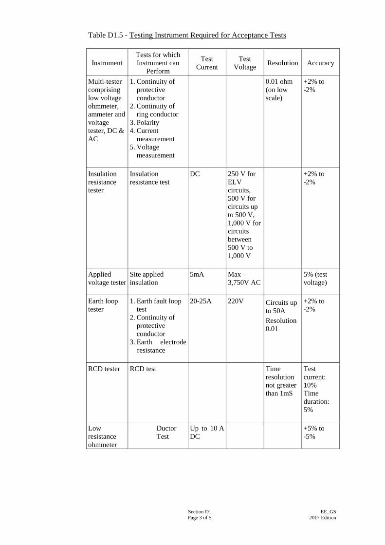
Section D1 Page 3 of 5
EE_GS 2017 Edition
Table D1.5 - Testing Instrument Required for Acceptance Tests
Instrument
Tests for which Instrument can
Perform
Test Current
Test Voltage
Resolution
Accuracy
Multi-tester comprising low voltage ohmmeter, ammeter and voltage tester, DC & AC
1. Continuity of protective conductor
2. Continuity of ring conductor
3. Polarity 4. Current
measurement 5. Voltage
measurement
0.01 ohm (on low scale)
+2% to -2%
Insulation resistance tester
Insulation resistance test
DC 250 V for ELV circuits, 500 V for circuits up to 500 V, 1,000 V for circuits between 500 V to 1,000 V
+2% to -2%
Applied voltage tester
Site applied insulation
5mA Max – 3,750V AC
5% (test voltage)
Earth loop tester
1. Earth fault loop test
2. Continuity of protective conductor
3. Earth electrode resistance
20-25A 220V Circuits up to 50A Resolution 0.01
+2% to -2%
RCD tester
RCD test Time resolution not greater than 1mS
Test current: 10% Time duration: 5%
Low resistance ohmmeter
Ductor Test
Up to 10 A DC
+5% to -5%
Section D1 Page 4 of 5
EE_GS 2017 Edition
D1.6 READINESS FOR INSPECTION, TESTING AND COMMISSIONING The EE Contractor is required to check the completion of the works to be inspected, tested or commissioned, the associated builder’s works, the associated building services installations and all other prerequisites to ensure that inspection, testing and commissioning can be proceeded in a safe and satisfactory manner without obstruction.
D1.7 "TYPE-TEST" CERTIFICATE "Type-test" for materials and equipment, where specified, shall be carried out at the manufacturer’s works, recognised institutions or accredited laboratories, or elsewhere as approved in order to demonstrate their compliance with the specified requirements. "Type-test" certificates together with the corresponding drawings, sketches, reports and any other necessary documents shall be submitted to the Supervising Officer for approval before delivery of the materials and equipment.
D1.8 OFF-SITE TESTS / FACTORY TESTS Factory tests and off-site tests as required shall be carried out at the manufacturer’s works, laboratories by independent regulatory/testing bodies, independent accredited laboratories or elsewhere as approved. This shall include quality control tests and general inspection tests in factory recommended by the manufacturer or for compliance with relevant standards. Where collection of test samples on the Site is required for the off-site tests, the EE Contractor shall submit the sampling and analysis methodology, including but not limited to the proposed independent accredited laboratory and the procedures for collection and analysis of test samples and submission of test results, for the Supervising Officer’s approval. The EE Contractor shall notify in advance the date for collection of test samples to the Supervising Officer’s Representative, who shall supervise the sampling, transport and delivery of the test samples. Collection of test samples shall be conducted by the independent accredited laboratory unless otherwise agreed by the Supervising Officer. The collected test samples shall be kept in sealed and locked containers inaccessible to unauthorised persons at all times. The test results in sealed envelope shall be submitted by the independent accredited laboratory to the Supervising Officer directly. Where specified, performance tests shall be carried out in factory for each or some of the offered equipment before delivery. After the performance tests, factory test report/certificate certified by a qualified factory engineer shall be submitted in duplicate to the Supervising Officer for approval immediately after the tests and before the equipment is dispatched from the manufacturer’s works. Factory tests shall be witnessed by an independent approved agency where specified. The EE Contractor shall note that the Supervising Officer may require witnessing the tests and inspection of locally and/or overseas manufactured equipment during construction at the manufacturer’s works.
Section D1 Page 5 of 5
EE_GS 2017 Edition
D1.9 SITE TESTS The EE Contractor shall carry out site tests for all system installations during construction period for individual components and/or part of the installed works to ensure safe and proper operation of the complete installations according to the specified requirements. Site tests for electrical works in the Installations shall comply with the COP for the Electricity (Wiring) Regulations unless otherwise specified. Registered or suitably qualified workers shall be deployed to conduct site tests, where applicable, for the Installations. Works to be permanently covered up shall be subject to inspection and testing before covering up. If the Supervising Officer or his Representative discovers any work that has been covered up before inspection and testing, this work shall be uncovered for inspection and testing to the satisfaction of the Supervising Officer or his Representative

Section D2 Page 1 of 2
EE_GS 2017 Edition
SECTION D2
INSPECTION
D2.1 INSPECTION OF MATERIALS AND EQUIPMENT DELIVERED TO SITE
The EE Contractor shall provide details of materials and equipment delivered to the Site including, but not limited to, brand name, model number, country of origin (if specified), their tested standards and record of Supervising Officer’s approval, purchase order, delivery order, record of delivery, payment vouchers, ex-factory certificate and shipping voucher, and all other relevant documents as applicable to the Supervising Officer for identification and verification of the materials and equipment delivered to the Site are in compliance with the approved submissions.
D2.2 VISUAL INSPECTION AND CHECKING
The EE Contractor shall be responsible for arranging adequate provisions to facilitate visual inspections and checking of the work in progress to be carried out by the Supervising Officer or his Representative from time to time during the construction period. The EE Contractor shall keep such inspection record for checking from time to time. Any defective works or sub-standard works found during visual inspection and checking shall be rectified or replaced before proceeding with further tests.
Visual inspection and checking shall include but not limited to the inspection and verification of the installed equipment being the approved brands and models and checking of any visible damages (such as scratches or dents, or painting problems) found on the equipment surface. A visual inspection shall be carried out in accordance with Code 21A and Code 21C of the COP before testing of the installations in order to verify the following: (a) The installation has been carried out in compliance with regulations and/or
COP; (b) The correctness of the designation of the installation; and (c) There is no visual damage to the installation.
D2.3 HANDOVER INSPECTION
The EE Contractor shall carry out detailed inspections for all components and equipment installed by him and make all necessary checking including operational settings for all equipment and systems in accordance with the instructions and recommendations from the manufacturer and to the satisfaction of the Supervising Officer before the handover of the Installations.
Section D2 Page 2 of 2
EE_GS 2017 Edition
If it is considered difficult or impossible to gain access to a part or parts of the complete installation for dismantling or maintenance purposes, the EE Contractor shall be required to carry out demonstrations on dismantling and assembling those parts of the installation to confirm the provisions are adequate. The EE Contractor shall be responsible for carrying out all necessary modification work at no additional cost to the Employer to alleviate the difficulties associated with dismantling or maintenance access.
The EE Contractor shall note that the Installations cannot be handed over until all the foregoing requirements where applicable have been carried out to the satisfaction of the Supervising Officer. The EE Contractor shall provide the following documents and data before the handover inspection:- (a) Test Certificates
Test records/certificates where applicable shall be provided:-
(i) Copies of manufacturer’s works test records/certificates on electrical installation items; (ii) Copies of electrical test records/certificates for works carried out on site; and (iii) Copies of works completion certificates for electrical works;
(b) "As-built" Drawings
"As-built" drawings as detailed in the contract documents shall be provided.
(c) Operation and Maintenance Manuals and User Manual
O&M Manuals and User Manual as detailed in the contract documents shall be provided.
D2.4 INSPECTION AND FUNCTIONAL TEST OF INSTALLED WORKS The EE Contractor shall carry out the tests and inspections as shown in the following sections and record the test results as agreed between the Supervising Officer or his Representative and the EE Contractor. Registered or suitably qualified electrical workers shall be employed to conduct such tests.
Section D3 Page 1 of 2
EE_GS 2017 Edition
SECTION D3
TESTING AND COMMISSIONING
D3.1 GENERAL Where testing and commissioning works for the Installations are required to be witnessed by the Supervising Officer or his Representative, the EE Contractor shall carry out the proper testing and commissioning works to his satisfaction before inviting them to witness the works. The EE Contractor shall arrange to enable the Supervising Officer or his Representative to witness the complete testing and commissioning. Unless otherwise approved by the Supervising Officer, testing and commissioning works carried out by the EE Contractor in the absence of the Supervising Officer or his Representative shall not be accepted as the approved test record. Any defects of alignment, adjustment, workmanship, materials and performance or other irregularities which become apparent during commissioning or testing shall be rectified by the EE Contractor and the relevant part of the commissioning or testing procedure shall be repeated at the EE Contractor’s own expense.
D3.2 PROCEDURES, STANDARDS AND REQUIREMENTS The EE Contractor shall follow relevant approved standards, procedures, guidelines in the testing and commissioning works, which shall include but not limited to:- (a) Statutory obligations and requirements, specifications and standards
specified in Part A; (b) Testing and Commissioning Procedure for Electrical Installation in
Government Buildings of the Hong Kong Special Administrative Region issued by BSB, ArchSD;
(c) Detailed inspection, testing and commissioning methods and procedures
approved by the Supervising Officer; and (d) Equipment manufacturers’ recommendations and specifications, if any.
D3.3 MASTER PROGRAMME FOR TESTING AND COMMISSIONING WORKS The EE Contractor is required to submit a programme for testing and commissioning works within the first three months after acceptance of his Tender. The programme shall indicate the tentative dates of all tests and commissioning works that will be carried out throughout the Conditions and all necessary submissions and approval relating to testing and commissioning. The EE Contractor shall ensure that the testing and commissioning programme matches the master programme for construction and that all testing and commissioning
Section D3 Page 2 of 2
EE_GS 2017 Edition
works are complete before the prescribed or extended date for completion of the Works. The programme shall also be updated as the Installations progress towards completion. The programme shall detail the types of testing and commissioning works required, the breakdown of the programme into floor-by-floor and/or area-by-area basis, the tests that are required during construction and before completion of the Installations, the period of each test with float time allowed, the milestone dates for the key activities of works etc. Critical path programme shall be submitted. The EE Contractor shall plan the programme so as to minimise the overlapping of different tests arranged simultaneously in different locations of the Site. A detailed checklist of all the Installations to be commissioned and tested shall be submitted at the same time. The checklist will be used for progress monitoring and shall be updated from time to time as the Installations progress towards completion
D3.4 DOCUMENTATION AND DELIVERABLES The EE Contractor shall submit full commissioning and testing report to the Supervising Officer within 14 days after completion of the commissioning and testing of the Installations. The report shall be in accordance with the requirements approved by the Supervising Officer.
D3.5 TESTING OF EMERGENCY LIGHTING, EXIT SIGN AND EMERGENCY GENERATOR INSTALLATIONS Where there are emergency lighting, exit sign and emergency generator installations included in the Installations, the EE Contractor shall be responsible for the following duties: (a) Confirmation to the Fire Service Contractor on the completion and
readiness of these installations for fire service inspection by FSD; (b) Provision of drawings and necessary information to the Fire Service
Contractor for inclusion in the submission to FSD for comments and inspection;
(c) Co-ordination with the Fire Service Contractor to inspect and witness the
final tests of these installations and rectification of any works found not complying with the fire service requirements of FSD; and
(d) Co-ordination with the Fire Service Contractor to carry out the final
functional test and performance test.
Section E1 Page 1 of 2
EE_GS 2017 Edition
PART E - TRAINING, INSPECTION, ATTENDANCE, OPERATION AND MAINTENANCE DURING MAINTENANCE PERIOD
SECTION E1
GENERAL REQUIREMENTS
E1.1 GENERAL
Unless otherwise specified in the Particular Specification, the EE Contractor shall provide training, inspection, attendance and operation and maintenance services for the Installations during Maintenance Period as specified in this General Specification. The EE Contractor shall supply and install, without additional cost to the Employer, replacements for any equipment or parts thereof, which may, in the opinion of the Supervising Officer, become unserviceable, especially where the causes are attributable to faulty materials, workmanship, or inadequate performance. In the execution of servicing and maintenance, repair and operation work on site, apart from transportation, necessary labour, tools, equipment and testing instruments, the EE Contractor shall also be responsible for keeping adequate stocks of spare parts/equipment and other items necessary to maintain all emergency repair in an efficient, satisfactory and safe operation condition at all time. The interruption of electricity supply and functioning of the Installations during execution of works shall be kept to the minimum. Such interruption shall only be allowed with the prior approval of the Supervising Officer or his representative. The EE Contractor shall also replace all burnt out or defective lamps or luminaires for failure or deficiency in performance at no cost to the Employer if the failure of the lamps and luminaires is still within the manufacturer’s guaranteed life period. The EE Contractor will be permitted to charge for the cost of lamps only if they fail beyond the guaranteed life period.
E1.2 COMPLETION OF OUTSTANDING AND DEFECTIVE WORKS After receiving the list of defects and outstanding works issued with the Certificate of Completion, the EE Contractor shall complete the outstanding works and rectify the defects concerned to the satisfaction of the Supervising Officer within the agreed time frame during the Maintenance Period. The EE Contractor shall also rectify as soon as practicable any defects identified within the Maintenance Period. The EE Contractor shall submit periodic report on the progress of outstanding and defective works to the Supervising Officer and attend inspection with the Supervising Officer’s Representatives to verify satisfactory completion of the outstanding and defective works.
Section E1 Page 2 of 2
EE_GS 2017 Edition
E1.3 REPAIR AND MAINTENANCE RECORDS The EE Contractor shall be responsible for maintaining a log book in each of the specific locations (e.g. switch room, plant room, etc.) agreed with the Supervising Officer or his representative. Every attendance and details of work done for the Installations including but not limited to repair, servicing and maintenance shall be entered into the log book by the EE Contractor so as to form a comprehensive record of attendance and works done. In addition, the EE Contractor shall also keep repair and maintenance records for the Installations in his own office and shall be required to forward such records for checking if so requested by the Supervising Officer.
Section E2 Page 1 of 1
EE_GS 2017 Edition
SECTION E2
TRAINING TO USERS AND OPERATION AND MAINTENANCE AGENTS
E2.1 GENERAL Training for the operation and maintenance of system and equipment shall be provided and arranged by the EE Contractor. The training shall include all training facilities, material and handouts etc. The EE Contractor shall submit a “Training Schedule” at least 3 months prior to the prescribed or extended date for the completion of Works for the Supervising Officer’s approval. The schedule shall include but not limited to the following requirements: Facilities and training programmes to ensure that the users and operation and maintenance agents acquire full knowledge and appreciation of all aspects of the design, day-to-day operation, breakdown and routine maintenance, diagnosis and hence capable to effectively and efficiently operate and maintain the system/equipment; All aspects of operation and maintenance of the plant including the use of special tools, and equipment portfolio for major systems covering quantity of equipment, equipment cost, recommended serviceable life by the manufacturer and cycle of major overhaul; Details and duration of the training course(s), qualifications of the instructor and the qualification requirements for the trainee(s); Full details of the training syllabus, including principles, theory and practical “hands-on” demonstration to reach the required depth of appreciation;
Section E3 Page 1 of 4
EE_GS 2017 Edition
SECTION E3
INSPECTION, ATTENDANCE, OPERATION AND MAINTENANCE REQUIREMENTS
E3.1 RESPONSE AND ATTENDANCE TO EMERGENCY AND FAULT CALLS The EE Contractor shall attend to emergency, fault and complaint calls arising from defective work materials and/or system operation at any time within the time limit according to the category of urgency stipulated below during the Maintenance Period and rectifies all defects leading to fault or breakdown of the equipment and/or system. The costs for the attendance, labour, materials and spare parts for repair, submission of fault/breakdown reports, etc. are deemed to have been allowed for in the Tender. (a) VERY URGENT
This refers to installation breakdown i.e. interruption more than one final sub-circuit, system or equipment failure bearing safety implication or seriously affecting the operation of the whole system. Emergency fault includes failure of switchboard, pipe burst or water dripping which may jeopardize the electrical installation, fire alarm and all types of electricity supply system failure or other situation the Supervising Officer or his representative shall determine. For Very Urgent situation, the EE Contractor shall attend to the call immediately.
(b) URGENT This refers to unsatisfactory services including individual lamp or socket outlet failure not involving more than one final sub-circuit and abnormality of equipment operation. Under this circumstance, the EE Contractor shall attend the Urgent calls within one hour from the receipt of the calls and provide temporary/permanent repair within 1 day after the receipt of the calls.
(c) NON URGENT This refers to any incident for anything that is not as serious as being included in (a) or (b) above. The EE Contractor shall attend the Non Urgent calls within 4 hours from receipt of the calls. The EE Contractor shall promptly complete any repair necessary for resuming the breakdown installation. In case immediate permanent repair is not possible due to safety related reason, the following "time for repair" targets counted from the receipt of breakdown or fault call shall be complied with:
(i) Complete temporary repair for resumption of the suspended or
breakdown services to a safe operating condition within 24 hours; and
Section E3 Page 2 of 4
EE_GS 2017 Edition
(ii) Complete permanent rectification works within 3 and 7 working
days unless long component and parts delivery time is required.
If the EE Contractor fails to respond promptly within the specified period, the EE Contractor shall immediately contact the Supervising Officer or his representative and provide sufficient justification for his incapability to comply with the requirement of response.
E3.2 MAINTENANCE SCHEDULE The EE Contractor shall prepare and submit the maintenance programme before the commencement of the Maintenance Period for the approval of the Supervising Officer. Upon the approval of the above maintenance programme and before the commencement of the Maintenance Period, the EE Contractor shall prepare a comprehensive maintenance schedule for all Installations and indicate dates for routine and periodic inspection, servicing and maintenance of the Installations. The schedule shall include but not limited to the following: - Infra-red scan of bus duct at 3 months interval;
- servicing of switchgear at L.V. switchboard at 6 months interval; and
- calibration of the instruments of L.V. switchboard at 6 months interval.
E3.3 INSPECTION DURING MAINTENANCE PERIOD The EE Contractor shall, in addition to the routine servicing and maintenance, make further inspections for the Installations to check and, if necessary, re-adjust the equipment/systems to meet the actual operation conditions and to test the Installations to meet statutory requirements including the submission of test reports and certificates.
E3.4 JOINT INSPECTION AT THE END OF MAINTENANCE PERIOD The EE Contractor shall attend inspections to the Installations at the expiry of the Maintenance Period in order to facilitate the acceptance and handing over of the Installations to the Employer’s operation and maintenance agents. The EE Contractor shall conduct site checking and make necessary adjustments to the equipment/systems one month before expiry of the Maintenance Period to ensure that the Installations are in good working order, safe and satisfactory operation condition for handover.
E3.5 FINAL INSPECTION BEFORE THE END OF MAINTENANCE PERIOD FOR LOW VOLTAGE CUBICLE SWITCHBOARD The following tests shall be carried out before the expiry date of the Maintenance Period or at a timing specified by the Supervising Officer if he considers that the
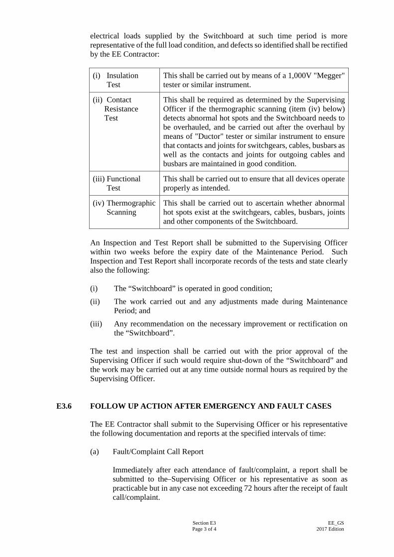
Section E3 Page 3 of 4
EE_GS 2017 Edition
electrical loads supplied by the Switchboard at such time period is more representative of the full load condition, and defects so identified shall be rectified by the EE Contractor: (i) Insulation Test
This shall be carried out by means of a 1,000V "Megger" tester or similar instrument.
(ii) Contact Resistance Test
This shall be required as determined by the Supervising Officer if the thermographic scanning (item (iv) below) detects abnormal hot spots and the Switchboard needs to be overhauled, and be carried out after the overhaul by means of "Ductor" tester or similar instrument to ensure that contacts and joints for switchgears, cables, busbars as well as the contacts and joints for outgoing cables and busbars are maintained in good condition.
(iii) Functional Test
This shall be carried out to ensure that all devices operate properly as intended.
(iv) Thermographic Scanning
This shall be carried out to ascertain whether abnormal hot spots exist at the switchgears, cables, busbars, joints and other components of the Switchboard.
An Inspection and Test Report shall be submitted to the Supervising Officer within two weeks before the expiry date of the Maintenance Period. Such Inspection and Test Report shall incorporate records of the tests and state clearly also the following: (i) The “Switchboard” is operated in good condition;
(ii) The work carried out and any adjustments made during Maintenance Period; and
(iii) Any recommendation on the necessary improvement or rectification on the “Switchboard”.
The test and inspection shall be carried out with the prior approval of the Supervising Officer if such would require shut-down of the “Switchboard” and the work may be carried out at any time outside normal hours as required by the Supervising Officer.
E3.6 FOLLOW UP ACTION AFTER EMERGENCY AND FAULT CASES The EE Contractor shall submit to the Supervising Officer or his representative the following documentation and reports at the specified intervals of time: (a) Fault/Complaint Call Report
Immediately after each attendance of fault/complaint, a report shall be submitted to the Supervising Officer or his representative as soon as practicable but in any case not exceeding 72 hours after the receipt of fault call/complaint.
Section E3 Page 4 of 4
EE_GS 2017 Edition
(b) Equipment Breakdown Report The equipment breakdown report shall have full details of findings during investigation/examination on cause of breakdown, account of repair/replacement work done, suggested precaution and/or action required to prevent the recurrence of similar incident. Interim report with proposal for repair/replacement work shall be submitted to the Supervising Officer or his representative within 48 hours after the receipt of breakdown call. A full report shall be available immediately after the rectification of breakdown for submission to the Supervising Officer and his representative.
Sample format of log and system performance sheet and breakdown report shall be submitted to the Supervising Officer or his representative for approval 2 months before completion of the Installation. If sample format is approved, the EE Contractor shall provide at his own expenses all copies of log and system performance sheets and breakdown reports to be used within the Maintenance Period.
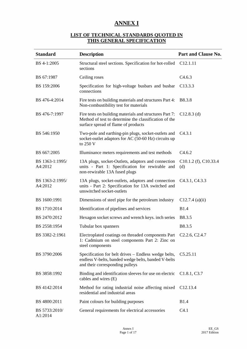
Annex I Page 1 of 17
EE_GS 2017 Edition
ANNEX I
LIST OF TECHNICAL STANDARDS QUOTED IN THIS GENERAL SPECIFICATION
Standard Description Part and Clause No.
BS 4-1:2005 Structural steel sections. Specification for hot-rolled sections
C12.1.11
BS 67:1987 Ceiling roses C4.6.3
BS 159:2006 Specification for high-voltage busbars and busbar connections
C13.3.3
BS 476-4:2014 Fire tests on building materials and structures Part 4: Non-combustibility test for materials
B8.3.8
BS 476-7:1997 Fire tests on building materials and structures Part 7: Method of test to determine the classification of the surface spread of flame of products
C12.8.3 (d)
BS 546:1950 Two-pole and earthing-pin plugs, socket-outlets and socket-outlet adaptors for AC (50-60 Hz) circuits up to 250 V
C4.3.1
BS 667:2005 Illuminance meters requirements and test methods C4.6.2
BS 1363-1:1995/ A4:2012
13A plugs, socket-Outlets, adaptors and connection units - Part 1: Specification for rewirable and non-rewirable 13A fused plugs
C10.1.2 (f), C10.33.4 (d)
BS 1363-2:1995/ A4:2012
13A plugs, socket-outlets, adaptors and connection units - Part 2: Specification for 13A switched and unswitched socket-outlets
C4.3.1, C4.3.3
BS 1600:1991 Dimensions of steel pipe for the petroleum industry C12.7.4 (a)(ii)
BS 1710:2014 Identification of pipelines and services B1.4
BS 2470:2012 Hexagon socket screws and wrench keys. inch series B8.3.5
BS 2558:1954 Tubular box spanners B8.3.5
BS 3382-2:1961 Electroplated coatings on threaded components Part 1: Cadmium on steel components Part 2: Zinc on steel components
C2.2.6, C2.4.7
BS 3790:2006 Specification for belt drives – Endless wedge belts, endless V-belts, banded wedge belts, banded V-belts and their corresponding pulleys
C5.25.11
BS 3858:1992 Binding and identification sleeves for use on electric cables and wires (E)
C1.8.1, C3.7
BS 4142:2014 Method for rating industrial noise affecting mixed residential and industrial areas
C12.13.4
BS 4800:2011 Paint colours for building purposes B1.4
BS 5733:2010/ A1:2014
General requirements for electrical accessories C4.1
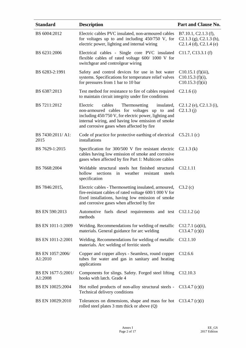
Annex I Page 2 of 17
EE_GS 2017 Edition
Standard Description Part and Clause No.
BS 6004:2012 Electric cables PVC insulated, non-armoured cables for voltages up to and including 450/750 V, for electric power, lighting and internal wiring
B7.10.1, C2.1.3 (f), C2.1.3 (g), C2.1.3 (h), C2.1.4 (d), C2.1.4 (e)
BS 6231:2006 Electrical cables - Single core PVC insulated flexible cables of rated voltage 600/ 1000 V for switchgear and controlgear wiring
C11.7, C13.3.1 (f)
BS 6283-2:1991 Safety and control devices for use in hot water systems. Specifications for temperature relief valves for pressures from 1 bar to 10 bar
C10.15.1 (f)(iii), C10.15.3 (f)(i), C10.15.3 (f)(ii)
BS 6387:2013 Test method for resistance to fire of cables required to maintain circuit integrity under fire conditions
C2.1.6 (i)
BS 7211:2012 Electric cables Thermosetting insulated, non-armoured cables for voltages up to and including 450/750 V, for electric power, lighting and internal wiring, and having low emission of smoke and corrosive gases when affected by fire
C2.1.2 (e), C2.1.3 (i), C2.1.3 (j)
BS 7430:2011/ A1: 2015
Code of practice for protective earthing of electrical installations
C5.21.1 (c)
BS 7629-1:2015 Specification for 300/500 V fire resistant electric cables having low emission of smoke and corrosive gases when affected by fire Part 1: Multicore cables
C2.1.3 (k)
BS 7668:2004 Weldable structural steels hot finished structural hollow sections in weather resistant steels specification
C12.1.11
BS 7846:2015, Electric cables - Thermosetting insulated, armoured, fire-resistant cables of rated voltage 600/1 000 V for fixed installations, having low emission of smoke and corrosive gases when affected by fire
C3.2 (c)
BS EN 590:2013 Automotive fuels diesel requirements and test methods
C12.1.2 (a)
BS EN 1011-1:2009 Welding. Recommendations for welding of metallic materials. General guidance for arc welding
C12.7.1 (a)(ii), C13.4.7 (c)(i)
BS EN 1011-2:2001 Welding. Recommendations for welding of metallic materials. Arc welding of ferritic steels
C12.1.10
BS EN 1057:2006/ A1:2010
Copper and copper alloys - Seamless, round copper tubes for water and gas in sanitary and heating applications
C12.6.6
BS EN 1677-5:2001/ A1:2008
Components for slings. Safety. Forged steel lifting hooks with latch. Grade 4
C12.10.3
BS EN 10025:2004 Hot rolled products of non-alloy structural steels - Technical delivery conditions
C13.4.7 (c)(i)
BS EN 10029:2010 Tolerances on dimensions, shape and mass for hot rolled steel plates 3 mm thick or above (Q)
C13.4.7 (c)(i)
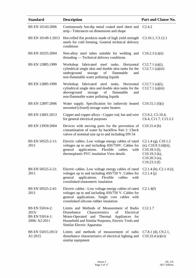
Annex I Page 3 of 17
EE_GS 2017 Edition
Standard Description Part and Clause No.
BS EN 10143:2006 Continuously hot-dip metal coated steel sheet and strip - Tolerances on dimensions and shape
C2.4.2
BS EN 10149-1:2013 Hot-rolled flat products made of high yield strength steels for cold forming. General technical delivery conditions
C3.10.1, C3.12.1
BS EN 10255:2004 Non-alloy steel tubes suitable for welding and threading — Technical delivery conditions
C10.2.3 (c)(ii)
BS EN 12885:1999 Workshop fabricated steel tanks. Horizontal cylindrical single skin and double skin tanks for the underground storage of flammable and non-flammable water polluting liquids
C12.7.1 (a)(i), C12.7.1 (a)(iii)
BS EN 12885:1999 Workshop fabricated steel tanks. Horizontal cylindrical single skin and double skin tanks for the aboveground storage of flammable and non-flammable water polluting liquids
C12.7.1 (a)(i), C12.7.1 (a)(iii)
BS EN 12897:2006 Water supply. Specification for indirectly heated unvented (closed) storage water heaters
C10.15.1 (f)(i)
BS EN 13601:2013 Copper and copper alloys - Copper rod, bar and wire for general electrical purposes
C5.9.2, C5.10.4, C6.4, C11.7, C13.3.3
BS EN 13959:2004 Devices with moving parts for the prevention of contamination of water by backflow Part 1: Check valves of nominal size up to and including DN 54
C10.15.4 (b)
BS EN 50525-2-11: 2011
Electric cables. Low voltage energy cables of rated voltages up to and including 450/750V. Cables for general applications. Flexible cables with thermoplastic PVC insulation View details
C2.1.4 (g), C10.1.2 (e), C10.9.3 (d)(ii), C10.18.3 (l), C10.19.3 (k), C10.20.3 (n), C10.23.3 (f)
BS EN 50525-2-21: 2011
Electric cables. Low voltage energy cables of rated voltages up to and including 450/750 V. Cables for general applications. Flexible cables with crosslinked elastomeric insulation
C2.1.4 (h), C2.1.4 (i), C2.1.4 (j)
BS EN 50525-2-41: 2011
Electric cables - Low voltage energy cables of rated voltages up to and including 450/750 V. Cables for general applications. Single core cables with crosslinked silicone rubber insulation
C2.1.4(f)
BS EN 55014-2: 2015/ BS EN 55014-1: 2006/ A2:2011
Limits and Methods of Measurement of Radio Disturbance Characteristics of Electrical Motor-Operated and Thermal Appliances for Household and Similar Purposes, Electric Tools and Similar Electric Apparatus
C12.1.7
BS EN 55015:2013/ A1:2015
Limits and methods of measurement of radio disturbance characteristics of electrical lighting and similar equipment
C7.8.1 (d), C9.2.1, C10.33.4 (e)(vi)
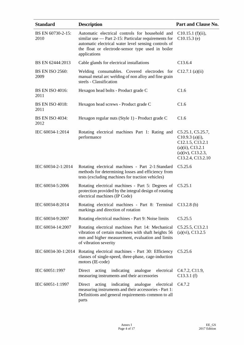
Annex I Page 4 of 17
EE_GS 2017 Edition
Standard Description Part and Clause No.
BS EN 60730-2-15: 2010
Automatic electrical controls for household and similar use — Part 2-15: Particular requirements for automatic electrical water level sensing controls of the float or electrode-sensor type used in boiler applications
C10.15.1 (f)(ii), C10.15.3 (e)
BS EN 62444:2013 Cable glands for electrical installations C13.6.4
BS EN ISO 2560: 2009
Welding consumables. Covered electrodes for manual metal arc welding of non alloy and fine grain steels - Classification
C12.7.1 (a)(ii)
BS EN ISO 4016: 2011
Hexagon head bolts - Product grade C C1.6
BS EN ISO 4018: 2011
Hexagon head screws - Product grade C C1.6
BS EN ISO 4034: 2012
Hexagon regular nuts (Style 1) - Product grade C C1.6
IEC 60034-1:2014 Rotating electrical machines Part 1: Rating and performance
C5.25.1, C5.25.7, C10.9.3 (a)(i), C12.1.5, C13.2.1 (a)(ii), C13.2.1 (a)(iv), C13.2.3, C13.2.4, C13.2.10
IEC 60034-2-1:2014 Rotating electrical machines - Part 2-1:Standard methods for determining losses and efficiency from tests (excluding machines for traction vehicles)
C5.25.6
IEC 60034-5:2006 Rotating electrical machines - Part 5: Degrees of protection provided by the integral design of rotating electrical machines (IP Code)
C5.25.1
IEC 60034-8:2014 Rotating electrical machines - Part 8: Terminal markings and direction of rotation
C13.2.8 (b)
IEC 60034-9:2007 Rotating electrical machines - Part 9: Noise limits C5.25.5
IEC 60034-14:2007 Rotating electrical machines Part 14: Mechanical vibration of certain machines with shaft heights 56 mm and higher measurement, evaluation and limits of vibration severity
C5.25.5, C13.2.1 (a)(vi), C13.2.5
IEC 60034-30-1:2014 Rotating electrical machines - Part 30: Efficiency classes of single-speed, three-phase, cage-induction motors (IE-code)
C5.25.6
IEC 60051:1997 Direct acting indicating analogue electrical measuring instruments and their accessories
C4.7.2, C11.9, C13.3.1 (f)
IEC 60051-1:1997 Direct acting indicating analogue electrical measuring instruments and their accessories - Part 1: Definitions and general requirements common to all parts
C4.7.2
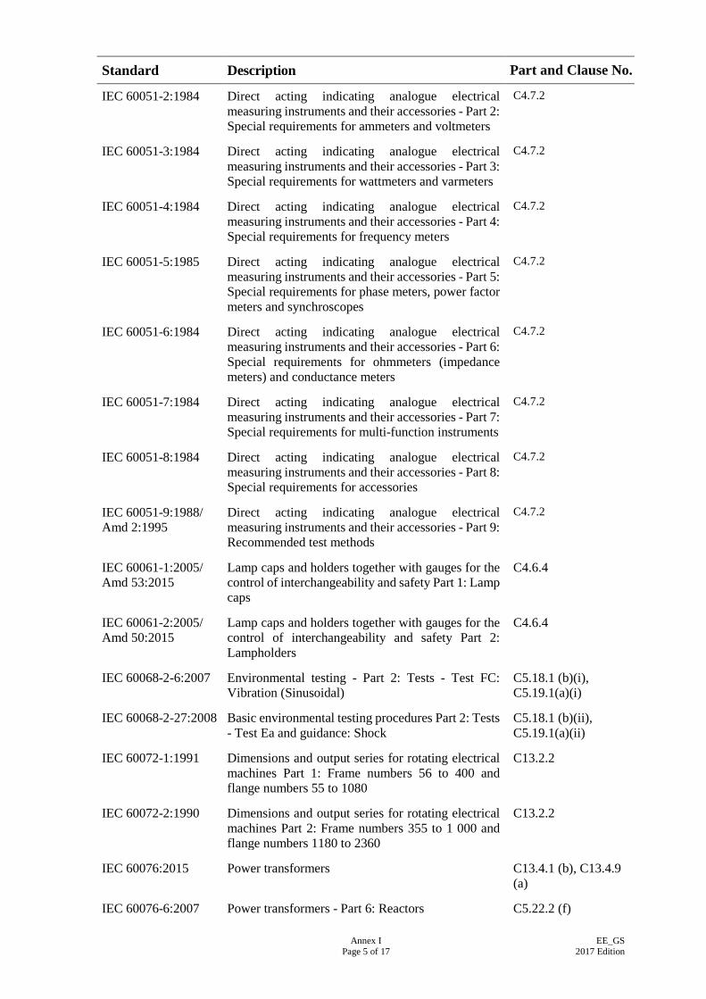
Annex I Page 5 of 17
EE_GS 2017 Edition
Standard Description Part and Clause No.
IEC 60051-2:1984 Direct acting indicating analogue electrical measuring instruments and their accessories - Part 2: Special requirements for ammeters and voltmeters
C4.7.2
IEC 60051-3:1984 Direct acting indicating analogue electrical measuring instruments and their accessories - Part 3: Special requirements for wattmeters and varmeters
C4.7.2
IEC 60051-4:1984 Direct acting indicating analogue electrical measuring instruments and their accessories - Part 4: Special requirements for frequency meters
C4.7.2
IEC 60051-5:1985 Direct acting indicating analogue electrical measuring instruments and their accessories - Part 5: Special requirements for phase meters, power factor meters and synchroscopes
C4.7.2
IEC 60051-6:1984 Direct acting indicating analogue electrical measuring instruments and their accessories - Part 6: Special requirements for ohmmeters (impedance meters) and conductance meters
C4.7.2
IEC 60051-7:1984 Direct acting indicating analogue electrical measuring instruments and their accessories - Part 7: Special requirements for multi-function instruments
C4.7.2
IEC 60051-8:1984 Direct acting indicating analogue electrical measuring instruments and their accessories - Part 8: Special requirements for accessories
C4.7.2
IEC 60051-9:1988/ Amd 2:1995
Direct acting indicating analogue electrical measuring instruments and their accessories - Part 9: Recommended test methods
C4.7.2
IEC 60061-1:2005/ Amd 53:2015
Lamp caps and holders together with gauges for the control of interchangeability and safety Part 1: Lamp caps
C4.6.4
IEC 60061-2:2005/ Amd 50:2015
Lamp caps and holders together with gauges for the control of interchangeability and safety Part 2: Lampholders
C4.6.4
IEC 60068-2-6:2007 Environmental testing - Part 2: Tests - Test FC: Vibration (Sinusoidal)
C5.18.1 (b)(i), C5.19.1(a)(i)
IEC 60068-2-27:2008 Basic environmental testing procedures Part 2: Tests - Test Ea and guidance: Shock
C5.18.1 (b)(ii), C5.19.1(a)(ii)
IEC 60072-1:1991 Dimensions and output series for rotating electrical machines Part 1: Frame numbers 56 to 400 and flange numbers 55 to 1080
C13.2.2
IEC 60072-2:1990 Dimensions and output series for rotating electrical machines Part 2: Frame numbers 355 to 1 000 and flange numbers 1180 to 2360
C13.2.2
IEC 60076:2015 Power transformers C13.4.1 (b), C13.4.9 (a)
IEC 60076-6:2007 Power transformers - Part 6: Reactors C5.22.2 (f)
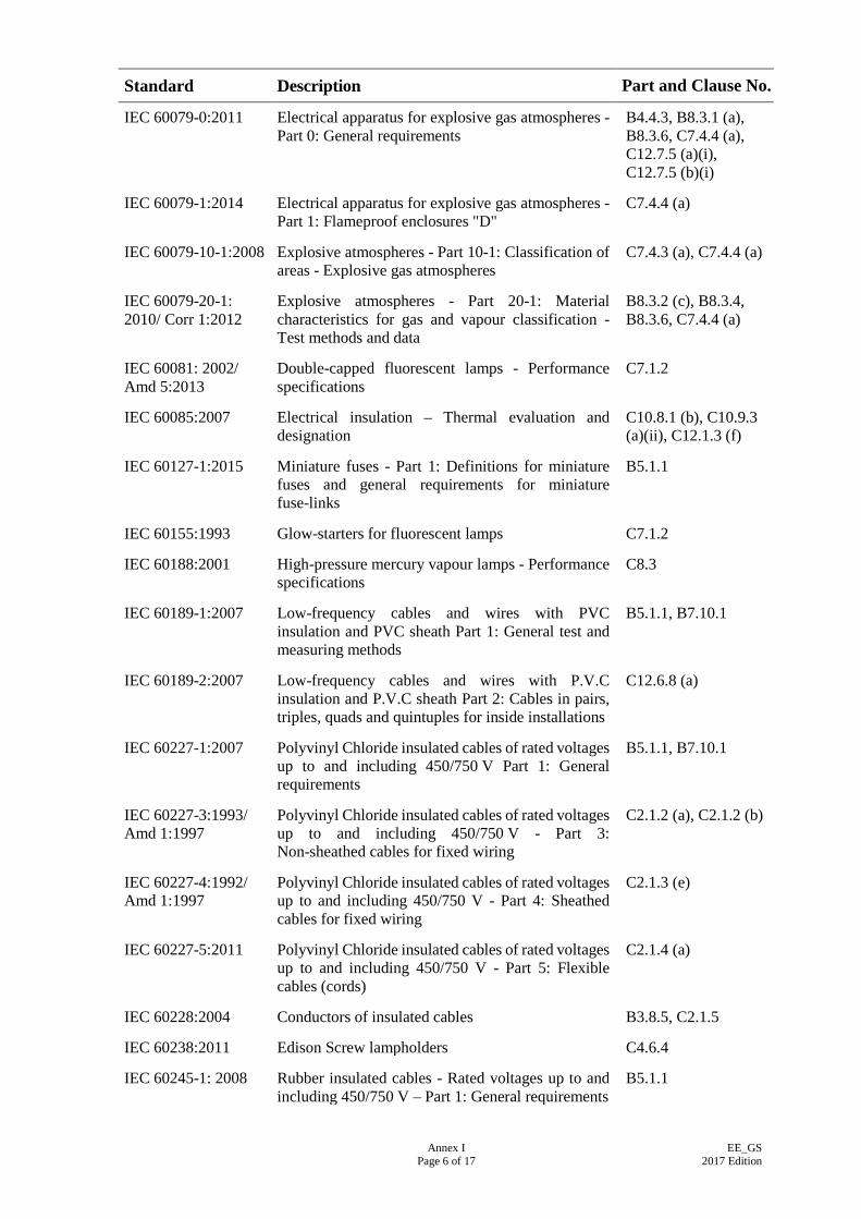
Annex I Page 6 of 17
EE_GS 2017 Edition
Standard Description Part and Clause No.
IEC 60079-0:2011 Electrical apparatus for explosive gas atmospheres - Part 0: General requirements
B4.4.3, B8.3.1 (a), B8.3.6, C7.4.4 (a), C12.7.5 (a)(i), C12.7.5 (b)(i)
IEC 60079-1:2014 Electrical apparatus for explosive gas atmospheres - Part 1: Flameproof enclosures "D"
C7.4.4 (a)
IEC 60079-10-1:2008 Explosive atmospheres - Part 10-1: Classification of areas - Explosive gas atmospheres
C7.4.3 (a), C7.4.4 (a)
IEC 60079-20-1: 2010/ Corr 1:2012
Explosive atmospheres - Part 20-1: Material characteristics for gas and vapour classification - Test methods and data
B8.3.2 (c), B8.3.4, B8.3.6, C7.4.4 (a)
IEC 60081: 2002/ Amd 5:2013
Double-capped fluorescent lamps - Performance specifications
C7.1.2
IEC 60085:2007 Electrical insulation – Thermal evaluation and designation
C10.8.1 (b), C10.9.3 (a)(ii), C12.1.3 (f)
IEC 60127-1:2015 Miniature fuses - Part 1: Definitions for miniature fuses and general requirements for miniature fuse-links
B5.1.1
IEC 60155:1993 Glow-starters for fluorescent lamps C7.1.2
IEC 60188:2001 High-pressure mercury vapour lamps - Performance specifications
C8.3
IEC 60189-1:2007 Low-frequency cables and wires with PVC insulation and PVC sheath Part 1: General test and measuring methods
B5.1.1, B7.10.1
IEC 60189-2:2007 Low-frequency cables and wires with P.V.C insulation and P.V.C sheath Part 2: Cables in pairs, triples, quads and quintuples for inside installations
C12.6.8 (a)
IEC 60227-1:2007 Polyvinyl Chloride insulated cables of rated voltages up to and including 450/750 V Part 1: General requirements
B5.1.1, B7.10.1
IEC 60227-3:1993/ Amd 1:1997
Polyvinyl Chloride insulated cables of rated voltages up to and including 450/750 V - Part 3: Non-sheathed cables for fixed wiring
C2.1.2 (a), C2.1.2 (b)
IEC 60227-4:1992/ Amd 1:1997
Polyvinyl Chloride insulated cables of rated voltages up to and including 450/750 V - Part 4: Sheathed cables for fixed wiring
C2.1.3 (e)
IEC 60227-5:2011 Polyvinyl Chloride insulated cables of rated voltages up to and including 450/750 V - Part 5: Flexible cables (cords)
C2.1.4 (a)
IEC 60228:2004 Conductors of insulated cables B3.8.5, C2.1.5
IEC 60238:2011 Edison Screw lampholders C4.6.4
IEC 60245-1: 2008 Rubber insulated cables - Rated voltages up to and including 450/750 V – Part 1: General requirements
B5.1.1
Annex I Page 7 of 17
EE_GS 2017 Edition
Standard Description Part and Clause No.
IEC 60245-3:1994/ Amd 1:1997/ Amd 2:2011
Rubber insulated cables - Rated voltages up to and including 450/750 V - Part 3: Heat resistant Silicone insulated cables
C2.1.4 (m)
IEC 60245-4:2011 Rubber insulated cables rated voltages up to and including 450/750 V Part 4: Cords and flexible cables
C2.1.4 (b), C2.1.4 (c)
IEC 60245-7:1994/ Amd 1:1997
Rubber insulated cables - Rated voltages up to and including 450/750 V - Part 7: Heat resistant Ethylene-Vinyl Acetate rubber insulated cables
C2.1.2. (c), C2.1.2 (d), C2.1.4 (k), C2.1.4 (l)
IEC 60255-1:2009 Measuring relays and protection equipment - Part 1: Common requirements
C5.5.2, C11.9, C13.3.1 (f)
IEC 60255-21-1:1988 Electrical relays - Part 21: Vibration, shock, bump and seismic tests on measuring relays and protection equipment - Section One: Vibration tests (sinusoidal)
C5.23.1 (f)
IEC 60255-21-2:1988 Electrical relays - Part 21: Vibration, shock, bump and seismic tests on measuring relays and protection equipment - Section Two: Shock and bump tests
C5.23.1 (f)
IEC 60255-26:2013 Measuring relays and protection equipment – Part 26: Electromagnetic compatibility requirements
C5.23.1 (b), C5.23.1 (f)
IEC 60269-1:2014 Low-voltage fuses - Part 1: General requirements C5.6.3, C5.8.2, C5.8.5, C5.26.4 (a)(xi), C6.6, C13.3.1 (f)
IEC 60269-2:2013 Low-voltage fuses – Part 2-1: Supplementary requirements for fuses for use by authorised persons (fuses mainly for industrial application) – Sections I to VI: Examples of types of standardised fuses
C5.8.5
IEC 60282-1:2014 High-voltage fuses - Part 1: Current-limiting fuses C13.3.1 (f), C13.5, C13.5 (g)
IEC 60296:2012 Fluids for electrotechnical applications unused mineral insulating oils for transformers and switchgear
C13.4.7 (c)(v)
IEC 60309-2:2012 Plugs, socket-outlets and couplers for industrial purposes – Part 2: Dimensional interchangeability requirements for pin and contact-tube accessories
C4.3.1
IEC 60332-1-1:2004/ Amd 1:2015
Tests on electric and optical fibre cables under fire conditions Part 1-1: Test for vertical flame propagation for a single insulated wire or cable Apparatus
C2.1.6 (ii)
IEC 60335-1:2013 Household and similar electrical appliances - Safety - Part 1: General requirements
C10.1.1 (b), C10.13.1 (a)
Annex I Page 8 of 17
EE_GS 2017 Edition
Standard Description Part and Clause No.
IEC 60335-2-2:2012 Household and similar electrical appliances – Safety – Part 2-2: Particular requirements for vacuum cleaners and water-suction cleaning appliances
C10.28.1 (a)
IEC 60335-2-3:2015 Household and similar electrical appliances – Safety – Part 2-3: Particular requirements for electric irons
C10.27.1 (b)
IEC 60335-2-6:2014 Household and similar electrical appliances – Safety – Part 2-6: Particular requirements for stationary cooking ranges, hobs, ovens and similar appliances
C10.19.1 (c), C10.20.1, C10.21.1
IEC 60335-2-9:2012 Household and similar electrical appliances – Safety – Part 2-9: Particular requirements for grills, toasters and similar portable cooking appliances
C10.23.1
IEC 60335-2-15:2012 Household and similar electrical appliances - Safety - Part 2-15: Particular requirements for appliances for heating liquids
C10.17.1 (a), C10.22.1 (a)
IEC 60335-2-21:2012 Household and similar electrical appliances - Safety - Part 2-21: Particular requirements for storage water heaters
C10.14.1 (d), C10.15.1 (f)(i)
IEC 60335-2-23:2012 Household and similar electrical appliances - Safety - Part 2-23: Particular requirements for appliances for skin or hair care
C10.24.1 (a)
IEC 60335-2-24:2012 Household and similar electrical appliances – Safety – Part 2-24: Particular requirements for refrigerating appliances, ice-cream appliances and ice-makers
C10.18.1 (c), C10.32.2 (a)
IEC 60335-2-30:2009 Household and similar electrical appliances - Safety - Part 2-30: Particular requirements for room heaters
C10.10.1 (a), C10.11.1 (a), C10.12.1 (a), C10.13.1 (a)
IEC 60335-2-40:2013 Household and similar electrical appliances – Safety – Part 2-40: Particular requirements for electrical heat pumps, air conditioners and dehumidifiers
C10.29.1 (a), C10.30.1 (a), C10.31.2 (a)
IEC 60335-2-75:2015 Safety of household and similar electrical appliances Part 2: Particular requirements for commercial dispensing appliances and vending machines
C10.16.1 (b)
IEC 60335-2-80:2015 Household and similar electrical appliances - Safety - Part 2-80: Particular requirements for fans
C10.2.1 (b)(ii), C10.3.1 (c)(i), C10.4.1 (c)(i), C10.5.1 (c)(i), C10.6.1 (c)(i), C10.7.1 (a)
IEC 60364:2015 Low-voltage electrical installations C5.9.4, D1.1
Annex I Page 9 of 17
EE_GS 2017 Edition
Standard Description Part and Clause No.
IEC 60364-1: 2005/ Corr 1: 2009
Low-voltage electrical installations – Part 1: Fundamental principles, assessment of general characteristics, definitions
B1.4, B2.2.4, B2.4.5 (m), B3.7.11 (b), B7.1, B7.7.4, B7.10.2
IEC 60364-4-44:2015 Electrical installations of buildings - Part 4-44: Protection for safety - Protection against voltage disturbances and electromagnetic disturbances
C5.17.2 (c)
IEC 60364-7-704:2005
Low-voltage electrical installations – Part 7-704: Requirements for special installations or locations – Construction and demolition site installations
A2.1.3 (h)
IEC 60376:2005 Specification of technical grade sulfur hexafluoride (SF6) for use in electrical equipment
C13.3.1 (f)
IEC 60400:2014/ Amd 2:2014
Lamp holders for tubular fluorescent lamps and starter holders
C7.1.2
IEC 60454-3-1: 2002 Pressure-sensitive adhesive tapes for electrical purposes Part 3 Specifications for individual materials Sheet 1: PVC film tapes with pressure-sensitive adhesive
C1.3
IEC 60502-1:2004/ Amd 1:2009
Power cables with extruded insulation and their accessories for rated voltages from 1 kV (Um = 1.2 kV) up to 30 kV (Um = 36 kV) - Part 1: Cables for rated voltages of 1 kV (Um = 1.2 kV) and 3 kV (Um = 3.6kV)
B8.4.8, C2.1.3 (a), C2.1.3 (b), C2.1.3 (c), C2.1.3 (d), C2.1.3 (l), C3.2 (a), C3.2 (b), C3.2 (f), C13.6.1
IEC 60502-2:2014 Power cables with extruded insulation and their accessories for rated voltages from 1 kV (Um = 1,2 kV) up to 30 kV (Um = 36 kV) - Part 2: Cables for rated voltages from 6 kV (Um = 7,2 kV) and up to 30 kV (Um = 36 kV)
C13.6.1
IEC 60529:2013/ Corr 2:2015
Degrees of protection provided by enclosures (IP Code)
C2.4.3, C4.2.1, C4.2.5, C4.3.1, C4.7.6, C5.1.5, C5.21.3(a), C6.2, C7.3.2, C7.4.2 (a), C7.4.3 (a), C7.4.4 (a), C8.5.1, C9.1.3, C11.4, C12.1.3 (c), C12.2.1, C12.7.3 (a)(v), C13.4.7 (b)
IEC 60570:2003 Electrical supply track systems for luminaires C4.6.1
IEC 60598-1:2014 Luminaires - Part 1: General requirements and tests C7.1.2, C7.3.2, C7.4.2 (a), C7.4.3 (a), C8.5.1, C9.1.2
IEC 60598-2-1:1979 Luminaires Part 2: Particular requirements section one - Fixed general purpose luminaires
C7.1.2, C7.1.5, C9.1.2, C9.1.3
IEC 60598-2-2:2011 Luminaires - Part 2: Particular requirements - Section 2: Recessed luminaires
C7.1.2, C7.1.5, C9.1.2, C9.1.3
Annex I Page 10 of 17
EE_GS 2017 Edition
Standard Description Part and Clause No.
IEC 60598-2-4: 1997 Luminaires - Part 2: Particular requirements – Section 4: Portable general purpose luminaires
C10.33.2 (a)
IEC 60598-2-5:2015 Luminaires - Part 2-5: Particular requirements - Floodlights
C8.5.1, C9.1.2
IEC 60598-2-22:2014 Luminaires - Part 2-22: Particular Requirements - Luminaires for emergency lighting
C7.5.2
IEC 60662:2011 High-pressure sodium vapour lamps C8.2, C8.4
IEC 60667-1:1980 Specification for vulcanized fibre for electrical purposes. Part 1: Definitions and general requirements
C6.11.2
IEC 60669-1 INTI: 2012
Switches for household and similar fixed-electrical installations - Part 1: General requirements
C4.2.1
IEC 60670-1:2015 Boxes and enclosures for electrical accessories for household and similar fixed electrical installations Part 1: General requirements
B5.2.1, B5.2.3, B5.6.1, B5.8, B7.6.4, B8.1.3, B8.1.4, B8.1.5, B8.2.7, B8.2.9, C2.2.3, C2.2.4, C2.2.5, C2.3.3, C4.1
IEC 60702-1:2002/ Amd 1:2015
Mineral insulated cables and their terminations with a rated voltage not exceeding 750 V Part 1: Cables
C3.2 (d), C3.2 (e)
IEC 60702-2:2015/ Amd 1:2015
Mineral insulated cables and their terminations with a rated voltage not exceeding 750 V Part 2: Terminations
B3.8.5, C3.2 (d), C3.2 (e)
IEC 60751:2008 Industrial platinum resistance thermometer sensors C13.2.11 (a)
IEC 60754-1:2011/ Corr 1:2013
Test on gases evolved during combustion of materials from cables - Part 1: Determination of the amount of Halogen acid gas
C2.1.6 (iv), C3.8.1
IEC 60838-2-2:2012 Miscellaneous lampholders – Part 2-2: Particular requirements – Connectors for LED modules
C9.3.1
IEC 60879:1986 Performance and construction of electric circulating fans and regulators
C10.2.1 (b)(i)
IEC 60898-1:2015/ Corr 1:2015
Electrical accessories - Circuit-breakers for overcurrent protection for household and similar installations - Part 1: Circuit-breakers for AC operation
C5.6.1, C5.6.2, C5.6.3
IEC 60901:2001/ Amd 6:2014
Single-capped fluorescent lamps - Performance specifications
C7.1.2
IEC 60921: 2006 Ballasts for tubular fluorescent lamps – Performance requirements
C7.1.2
IEC 60927:2013 Auxiliaries for lamps - Starting devices (other than glow starters) - Performance requirements
C7.1.2
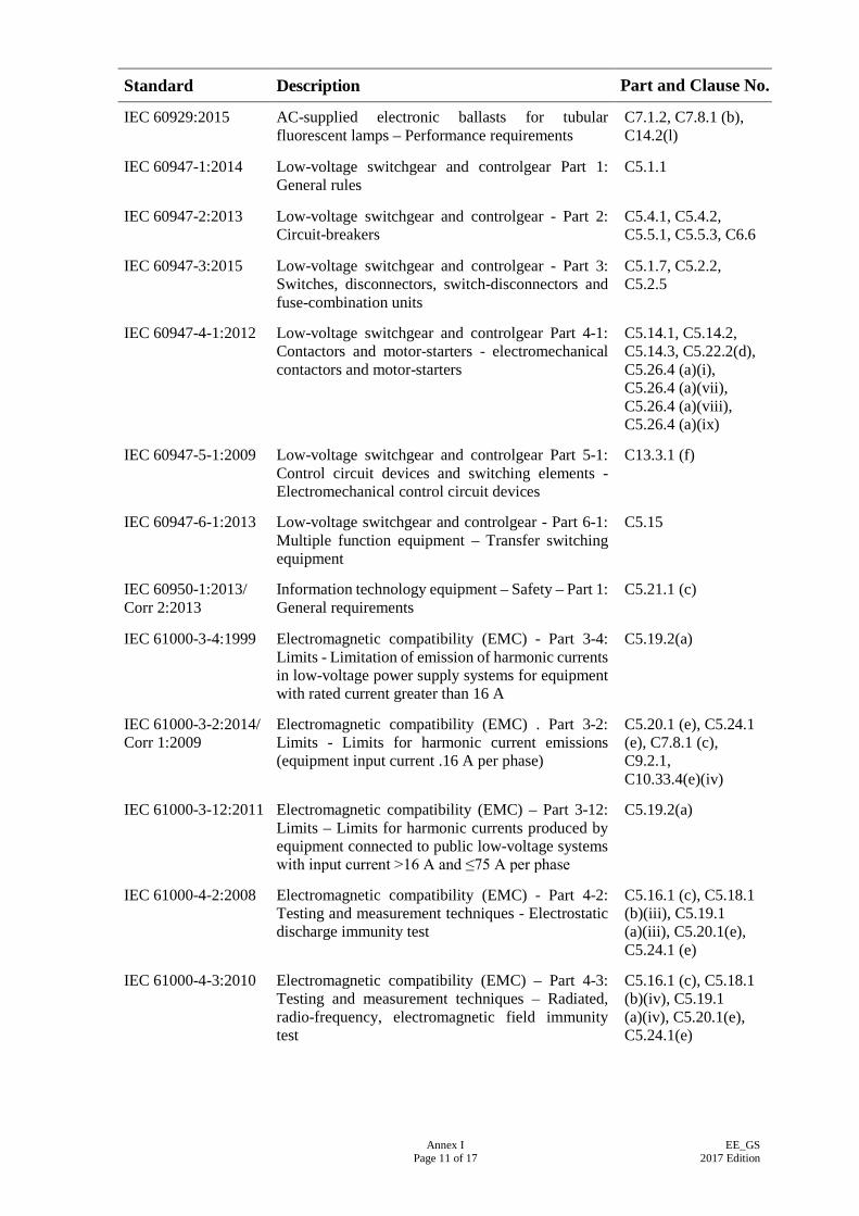
Annex I Page 11 of 17
EE_GS 2017 Edition
Standard Description Part and Clause No.
IEC 60929:2015 AC-supplied electronic ballasts for tubular fluorescent lamps – Performance requirements
C7.1.2, C7.8.1 (b), C14.2(l)
IEC 60947-1:2014 Low-voltage switchgear and controlgear Part 1: General rules
C5.1.1
IEC 60947-2:2013 Low-voltage switchgear and controlgear - Part 2: Circuit-breakers
C5.4.1, C5.4.2, C5.5.1, C5.5.3, C6.6
IEC 60947-3:2015 Low-voltage switchgear and controlgear - Part 3: Switches, disconnectors, switch-disconnectors and fuse-combination units
C5.1.7, C5.2.2, C5.2.5
IEC 60947-4-1:2012 Low-voltage switchgear and controlgear Part 4-1: Contactors and motor-starters - electromechanical contactors and motor-starters
C5.14.1, C5.14.2, C5.14.3, C5.22.2(d), C5.26.4 (a)(i), C5.26.4 (a)(vii), C5.26.4 (a)(viii), C5.26.4 (a)(ix)
IEC 60947-5-1:2009 Low-voltage switchgear and controlgear Part 5-1: Control circuit devices and switching elements - Electromechanical control circuit devices
C13.3.1 (f)
IEC 60947-6-1:2013 Low-voltage switchgear and controlgear - Part 6-1: Multiple function equipment – Transfer switching equipment
C5.15
IEC 60950-1:2013/ Corr 2:2013
Information technology equipment – Safety – Part 1: General requirements
C5.21.1 (c)
IEC 61000-3-4:1999 Electromagnetic compatibility (EMC) - Part 3-4: Limits - Limitation of emission of harmonic currents in low-voltage power supply systems for equipment with rated current greater than 16 A
C5.19.2(a)
IEC 61000-3-2:2014/ Corr 1:2009
Electromagnetic compatibility (EMC) . Part 3-2: Limits - Limits for harmonic current emissions (equipment input current .16 A per phase)
C5.20.1 (e), C5.24.1 (e), C7.8.1 (c), C9.2.1, C10.33.4(e)(iv)
IEC 61000-3-12:2011 Electromagnetic compatibility (EMC) – Part 3-12: Limits – Limits for harmonic currents produced by equipment connected to public low-voltage systems with input current >16 A and ≤75 A per phase
C5.19.2(a)
IEC 61000-4-2:2008 Electromagnetic compatibility (EMC) - Part 4-2: Testing and measurement techniques - Electrostatic discharge immunity test
C5.16.1 (c), C5.18.1 (b)(iii), C5.19.1 (a)(iii), C5.20.1(e), C5.24.1 (e)
IEC 61000-4-3:2010 Electromagnetic compatibility (EMC) – Part 4-3: Testing and measurement techniques – Radiated, radio-frequency, electromagnetic field immunity test
C5.16.1 (c), C5.18.1 (b)(iv), C5.19.1 (a)(iv), C5.20.1(e), C5.24.1(e)
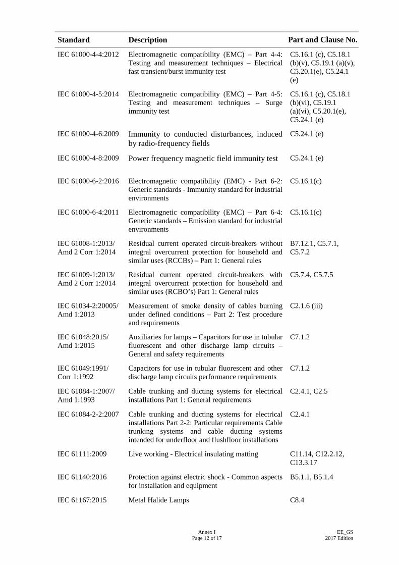
Annex I Page 12 of 17
EE_GS 2017 Edition
Standard Description Part and Clause No.
IEC 61000-4-4:2012 Electromagnetic compatibility (EMC) – Part 4-4: Testing and measurement techniques – Electrical fast transient/burst immunity test
C5.16.1 (c), C5.18.1 (b)(v), C5.19.1 (a)(v), C5.20.1(e), C5.24.1 (e)
IEC 61000-4-5:2014 Electromagnetic compatibility (EMC) – Part 4-5: Testing and measurement techniques – Surge immunity test
C5.16.1 (c), C5.18.1 (b)(vi), C5.19.1 (a)(vi), C5.20.1(e), C5.24.1 (e)
IEC 61000-4-6:2009 Immunity to conducted disturbances, induced by radio-frequency fields
C5.24.1 (e)
IEC 61000-4-8:2009 Power frequency magnetic field immunity test C5.24.1 (e)
IEC 61000-6-2:2016 Electromagnetic compatibility (EMC) - Part 6-2: Generic standards - Immunity standard for industrial environments
C5.16.1(c)
IEC 61000-6-4:2011 Electromagnetic compatibility (EMC) – Part 6-4: Generic standards – Emission standard for industrial environments
C5.16.1(c)
IEC 61008-1:2013/ Amd 2 Corr 1:2014
Residual current operated circuit-breakers without integral overcurrent protection for household and similar uses (RCCBs) – Part 1: General rules
B7.12.1, C5.7.1, C5.7.2
IEC 61009-1:2013/ Amd 2 Corr 1:2014
Residual current operated circuit-breakers with integral overcurrent protection for household and similar uses (RCBO’s) Part 1: General rules
C5.7.4, C5.7.5
IEC 61034-2:20005/ Amd 1:2013
Measurement of smoke density of cables burning under defined conditions – Part 2: Test procedure and requirements
C2.1.6 (iii)
IEC 61048:2015/ Amd 1:2015
Auxiliaries for lamps – Capacitors for use in tubular fluorescent and other discharge lamp circuits – General and safety requirements
C7.1.2
IEC 61049:1991/ Corr 1:1992
Capacitors for use in tubular fluorescent and other discharge lamp circuits performance requirements
C7.1.2
IEC 61084-1:2007/ Amd 1:1993
Cable trunking and ducting systems for electrical installations Part 1: General requirements
C2.4.1, C2.5
IEC 61084-2-2:2007 Cable trunking and ducting systems for electrical installations Part 2-2: Particular requirements Cable trunking systems and cable ducting systems intended for underfloor and flushfloor installations
C2.4.1
IEC 61111:2009 Live working - Electrical insulating matting C11.14, C12.2.12, C13.3.17
IEC 61140:2016 Protection against electric shock - Common aspects for installation and equipment
B5.1.1, B5.1.4
IEC 61167:2015 Metal Halide Lamps C8.4
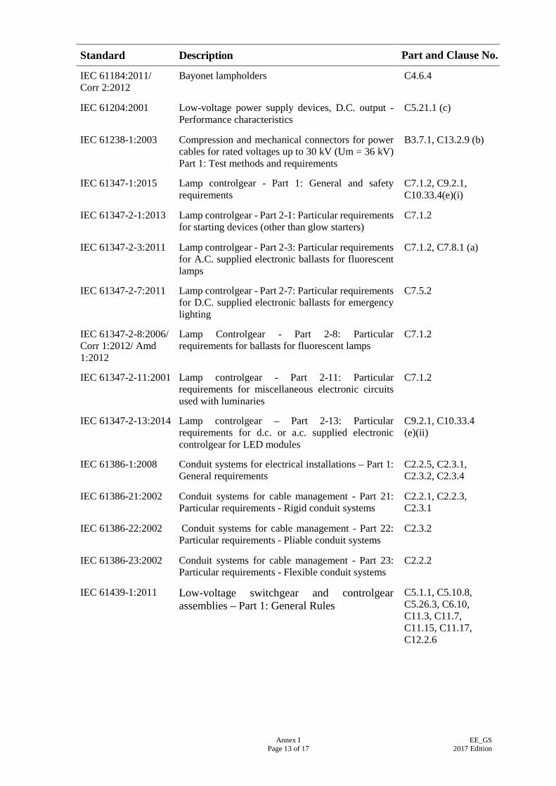
Annex I Page 13 of 17
EE_GS 2017 Edition
Standard Description Part and Clause No.
IEC 61184:2011/ Corr 2:2012
Bayonet lampholders C4.6.4
IEC 61204:2001 Low-voltage power supply devices, D.C. output - Performance characteristics
C5.21.1 (c)
IEC 61238-1:2003 Compression and mechanical connectors for power cables for rated voltages up to 30 kV (Um = 36 kV) Part 1: Test methods and requirements
B3.7.1, C13.2.9 (b)
IEC 61347-1:2015 Lamp controlgear - Part 1: General and safety requirements
C7.1.2, C9.2.1, C10.33.4(e)(i)
IEC 61347-2-1:2013 Lamp controlgear - Part 2-1: Particular requirements for starting devices (other than glow starters)
C7.1.2
IEC 61347-2-3:2011 Lamp controlgear - Part 2-3: Particular requirements for A.C. supplied electronic ballasts for fluorescent lamps
C7.1.2, C7.8.1 (a)
IEC 61347-2-7:2011 Lamp controlgear - Part 2-7: Particular requirements for D.C. supplied electronic ballasts for emergency lighting
C7.5.2
IEC 61347-2-8:2006/ Corr 1:2012/ Amd 1:2012
Lamp Controlgear - Part 2-8: Particular requirements for ballasts for fluorescent lamps
C7.1.2
IEC 61347-2-11:2001 Lamp controlgear - Part 2-11: Particular requirements for miscellaneous electronic circuits used with luminaries
C7.1.2
IEC 61347-2-13:2014 Lamp controlgear – Part 2-13: Particular requirements for d.c. or a.c. supplied electronic controlgear for LED modules
C9.2.1, C10.33.4 (e)(ii)
IEC 61386-1:2008 Conduit systems for electrical installations – Part 1: General requirements
C2.2.5, C2.3.1, C2.3.2, C2.3.4
IEC 61386-21:2002 Conduit systems for cable management - Part 21: Particular requirements - Rigid conduit systems
C2.2.1, C2.2.3, C2.3.1
IEC 61386-22:2002 Conduit systems for cable management - Part 22: Particular requirements - Pliable conduit systems
C2.3.2
IEC 61386-23:2002 Conduit systems for cable management - Part 23: Particular requirements - Flexible conduit systems
C2.2.2
IEC 61439-1:2011 Low-voltage switchgear and controlgear assemblies – Part 1: General Rules
C5.1.1, C5.10.8, C5.26.3, C6.10, C11.3, C11.7, C11.15, C11.17, C12.2.6
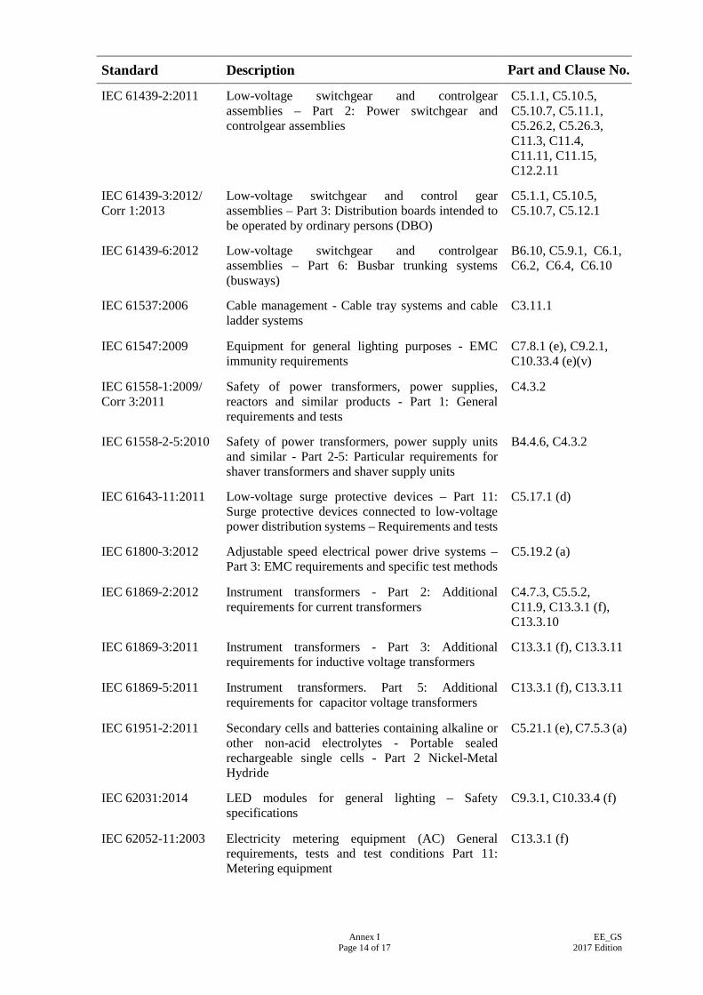
Annex I Page 14 of 17
EE_GS 2017 Edition
Standard Description Part and Clause No.
IEC 61439-2:2011 Low-voltage switchgear and controlgear assemblies – Part 2: Power switchgear and controlgear assemblies
C5.1.1, C5.10.5, C5.10.7, C5.11.1, C5.26.2, C5.26.3, C11.3, C11.4, C11.11, C11.15, C12.2.11
IEC 61439-3:2012/ Corr 1:2013
Low-voltage switchgear and control gear assemblies – Part 3: Distribution boards intended to be operated by ordinary persons (DBO)
C5.1.1, C5.10.5, C5.10.7, C5.12.1
IEC 61439-6:2012 Low-voltage switchgear and controlgear assemblies – Part 6: Busbar trunking systems (busways)
B6.10, C5.9.1, C6.1, C6.2, C6.4, C6.10
IEC 61537:2006 Cable management - Cable tray systems and cable ladder systems
C3.11.1
IEC 61547:2009 Equipment for general lighting purposes - EMC immunity requirements
C7.8.1 (e), C9.2.1, C10.33.4 (e)(v)
IEC 61558-1:2009/ Corr 3:2011
Safety of power transformers, power supplies, reactors and similar products - Part 1: General requirements and tests
C4.3.2
IEC 61558-2-5:2010 Safety of power transformers, power supply units and similar - Part 2-5: Particular requirements for shaver transformers and shaver supply units
B4.4.6, C4.3.2
IEC 61643-11:2011 Low-voltage surge protective devices – Part 11: Surge protective devices connected to low-voltage power distribution systems – Requirements and tests
C5.17.1 (d)
IEC 61800-3:2012 Adjustable speed electrical power drive systems – Part 3: EMC requirements and specific test methods
C5.19.2 (a)
IEC 61869-2:2012 Instrument transformers - Part 2: Additional requirements for current transformers
C4.7.3, C5.5.2, C11.9, C13.3.1 (f), C13.3.10
IEC 61869-3:2011 Instrument transformers - Part 3: Additional requirements for inductive voltage transformers
C13.3.1 (f), C13.3.11
IEC 61869-5:2011 Instrument transformers. Part 5: Additional requirements for capacitor voltage transformers
C13.3.1 (f), C13.3.11
IEC 61951-2:2011 Secondary cells and batteries containing alkaline or other non-acid electrolytes - Portable sealed rechargeable single cells - Part 2 Nickel-Metal Hydride
C5.21.1 (e), C7.5.3 (a)
IEC 62031:2014 LED modules for general lighting – Safety specifications
C9.3.1, C10.33.4 (f)
IEC 62052-11:2003 Electricity metering equipment (AC) General requirements, tests and test conditions Part 11: Metering equipment
C13.3.1 (f)
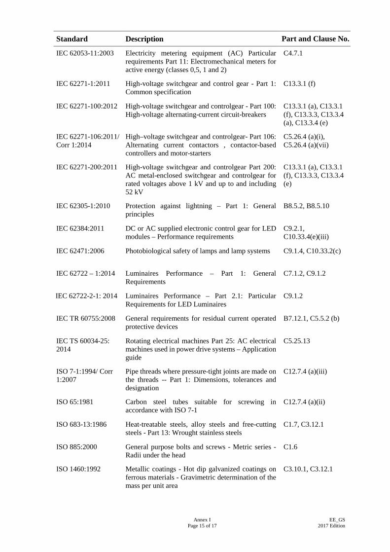
Annex I Page 15 of 17
EE_GS 2017 Edition
Standard Description Part and Clause No.
IEC 62053-11:2003 Electricity metering equipment (AC) Particular requirements Part 11: Electromechanical meters for active energy (classes 0,5, 1 and 2)
C4.7.1
IEC 62271-1:2011 High-voltage switchgear and control gear - Part 1: Common specification
C13.3.1 (f)
IEC 62271-100:2012 High-voltage switchgear and controlgear - Part 100: High-voltage alternating-current circuit-breakers
C13.3.1 (a), C13.3.1 (f), C13.3.3, C13.3.4 (a), C13.3.4 (e)
IEC 62271-106:2011/ Corr 1:2014
High–voltage switchgear and controlgear- Part 106: Alternating current contactors , contactor-based controllers and motor-starters
C5.26.4 (a)(i), C5.26.4 (a)(vii)
IEC 62271-200:2011 High-voltage switchgear and controlgear Part 200: AC metal-enclosed switchgear and controlgear for rated voltages above 1 kV and up to and including 52 kV
C13.3.1 (a), C13.3.1 (f), C13.3.3, C13.3.4 (e)
IEC 62305-1:2010 Protection against lightning – Part 1: General principles
B8.5.2, B8.5.10
IEC 62384:2011 DC or AC supplied electronic control gear for LED modules – Performance requirements
C9.2.1, C10.33.4(e)(iii)
IEC 62471:2006 Photobiological safety of lamps and lamp systems C9.1.4, C10.33.2(c)
IEC 62722 – 1:2014 Luminaires Performance – Part 1: General Requirements
C7.1.2, C9.1.2
IEC 62722-2-1: 2014 Luminaires Performance – Part 2.1: Particular Requirements for LED Luminaires
C9.1.2
IEC TR 60755:2008 General requirements for residual current operated protective devices
B7.12.1, C5.5.2 (b)
IEC TS 60034-25: 2014
Rotating electrical machines Part 25: AC electrical machines used in power drive systems – Application guide
C5.25.13
ISO 7-1:1994/ Corr 1:2007
Pipe threads where pressure-tight joints are made on the threads -- Part 1: Dimensions, tolerances and designation
C12.7.4 (a)(iii)
ISO 65:1981 Carbon steel tubes suitable for screwing in accordance with ISO 7-1
C12.7.4 (a)(ii)
ISO 683-13:1986 Heat-treatable steels, alloy steels and free-cutting steels - Part 13: Wrought stainless steels
C1.7, C3.12.1
ISO 885:2000 General purpose bolts and screws - Metric series - Radii under the head
C1.6
ISO 1460:1992 Metallic coatings - Hot dip galvanized coatings on ferrous materials - Gravimetric determination of the mass per unit area
C3.10.1, C3.12.1
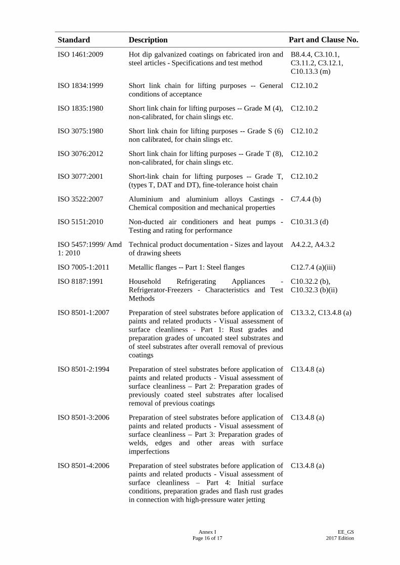
Annex I Page 16 of 17
EE_GS 2017 Edition
Standard Description Part and Clause No.
ISO 1461:2009 Hot dip galvanized coatings on fabricated iron and steel articles - Specifications and test method
B8.4.4, C3.10.1, C3.11.2, C3.12.1, C10.13.3 (m)
ISO 1834:1999 Short link chain for lifting purposes -- General conditions of acceptance
C12.10.2
ISO 1835:1980 Short link chain for lifting purposes -- Grade M (4), non-calibrated, for chain slings etc.
C12.10.2
ISO 3075:1980 Short link chain for lifting purposes -- Grade S (6) non calibrated, for chain slings etc.
C12.10.2
ISO 3076:2012 Short link chain for lifting purposes -- Grade T (8), non-calibrated, for chain slings etc.
C12.10.2
ISO 3077:2001 Short-link chain for lifting purposes -- Grade T, (types T, DAT and DT), fine-tolerance hoist chain
C12.10.2
ISO 3522:2007 Aluminium and aluminium alloys Castings - Chemical composition and mechanical properties
C7.4.4 (b)
ISO 5151:2010 Non-ducted air conditioners and heat pumps - Testing and rating for performance
C10.31.3 (d)
ISO 5457:1999/ Amd 1: 2010
Technical product documentation - Sizes and layout of drawing sheets
A4.2.2, A4.3.2
ISO 7005-1:2011 Metallic flanges -- Part 1: Steel flanges C12.7.4 (a)(iii)
ISO 8187:1991 Household Refrigerating Appliances - Refrigerator-Freezers - Characteristics and Test Methods
C10.32.2 (b), C10.32.3 (b)(ii)
ISO 8501-1:2007 Preparation of steel substrates before application of paints and related products - Visual assessment of surface cleanliness - Part 1: Rust grades and preparation grades of uncoated steel substrates and of steel substrates after overall removal of previous coatings
C13.3.2, C13.4.8 (a)
ISO 8501-2:1994 Preparation of steel substrates before application of paints and related products - Visual assessment of surface cleanliness – Part 2: Preparation grades of previously coated steel substrates after localised removal of previous coatings
C13.4.8 (a)
ISO 8501-3:2006 Preparation of steel substrates before application of paints and related products - Visual assessment of surface cleanliness – Part 3: Preparation grades of welds, edges and other areas with surface imperfections
C13.4.8 (a)
ISO 8501-4:2006 Preparation of steel substrates before application of paints and related products - Visual assessment of surface cleanliness – Part 4: Initial surface conditions, preparation grades and flash rust grades in connection with high-pressure water jetting
C13.4.8 (a)
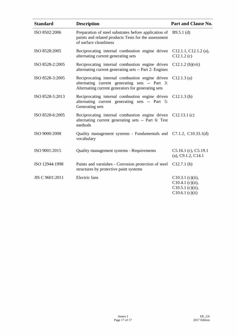
Annex I Page 17 of 17
EE_GS 2017 Edition
Standard Description Part and Clause No.
ISO 8502:2006 Preparation of steel substrates before application of paints and related products Tests for the assessment of surface cleanliness
B9.5.1 (d)
ISO 8528:2005 Reciprocating internal combustion engine driven alternating current generating sets
C12.1.1, C12.1.2 (a), C12.1.2 (c)
ISO 8528-2:2005 Reciprocating internal combustion engine driven alternating current generating sets -- Part 2: Engines
C12.1.2 (b)(vii)
ISO 8528-3:2005 Reciprocating internal combustion engine driven alternating current generating sets -- Part 3: Alternating current generators for generating sets
C12.1.3 (a)
ISO 8528-5:2013 Reciprocating internal combustion engine driven alternating current generating sets -- Part 5: Generating sets
C12.1.3 (b)
ISO 8528-6:2005 Reciprocating internal combustion engine driven alternating current generating sets -- Part 6: Test methods
C12.13.1 (c)
ISO 9000:2008 Quality management systems - Fundamentals and vocabulary
C7.1.2, C10.33.1(d)
ISO 9001:2015 Quality management systems - Requirements C5.16.1 (c), C5.19.1 (a), C9.1.2, C14.1
ISO 12944:1998 Paints and varnishes - Corrosion protection of steel structures by protective paint systems
C12.7.1 (b)
JIS C 9601:2011 Electric fans C10.3.1 (c)(ii), C10.4.1 (c)(ii), C10.5.1 (c)(ii), C10.6.1 (c)(ii)