general specification - universal instruments …graphiclib)/gs-406-03.pdf/...general specification...
TRANSCRIPT
4797 B/X/L/R HSPGS-406-03
4797 B/X/L/R HSPHigh Speed Chipshooter
Universal Part Number: GS-406-03Issued 12/03
Automation in Electronic AssemblyAutomation in Electronic AssemblyAutomation in Electronic AssemblyAutomation in Electronic AssemblyAutomation in Electronic Assembly
GeneralGeneralGeneralGeneralGeneral
SpeciSpeciSpeciSpeciSpecificaficaficaficaficationtiontiontiontion
Surface Mount Division of Universal InstrumentsSurface Mount Division of Universal InstrumentsSurface Mount Division of Universal InstrumentsSurface Mount Division of Universal InstrumentsSurface Mount Division of Universal Instruments

4797 B/X/L/R HSP GS-406-03
4797 B/X/L/R HSPGS-406-03
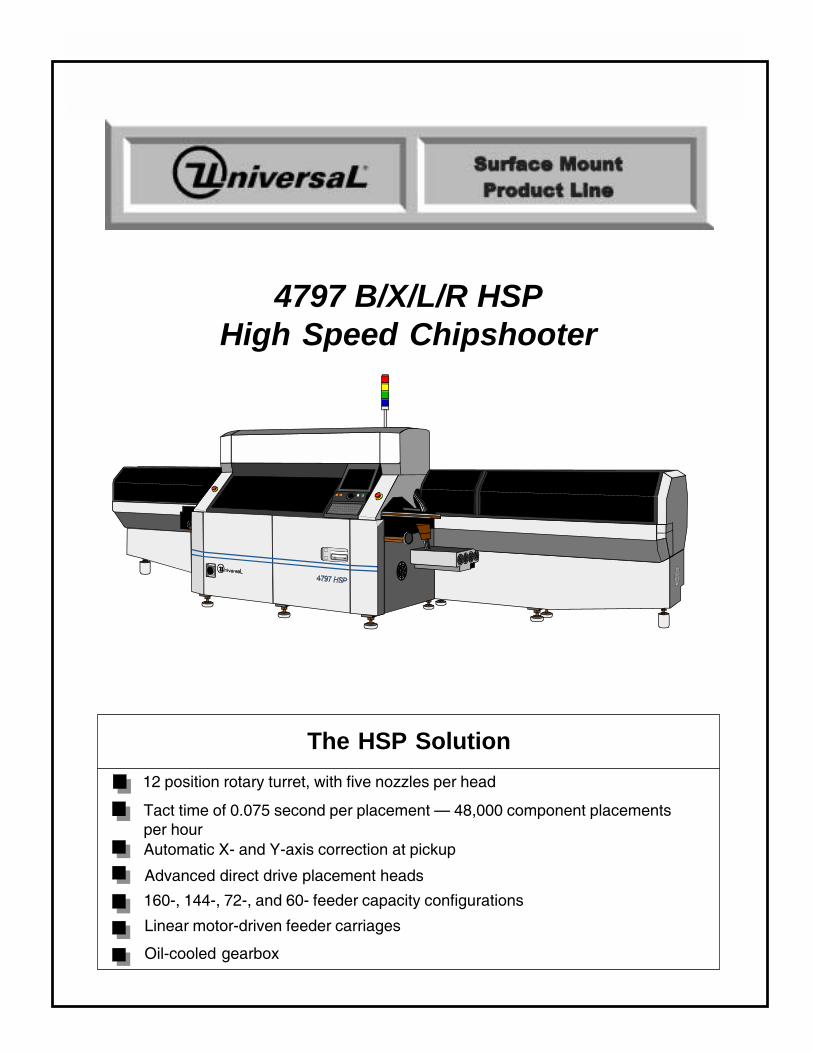
4797 B/X/L/R HSPHigh Speed Chipshooter
The HSP Solution12 position rotary turret, with five nozzles per head
Tact time of 0.075 second per placement � 48,000 component placementsper hourAutomatic X- and Y-axis correction at pickup
Advanced direct drive placement heads
160-, 144-, 72-, and 60- feeder capacity configurations
Linear motor-driven feeder carriages
Oil-cooled gearbox

4797 B/X/L/R HSP GS-406-03
4797 B/X/L/R HSPGS-406-03
Contents
Introduction ............................................................................................................... 1Functional Description ............................................................................................. 2Standard Features ..................................................................................................... 3
Turret Assembly ................................................................................................... 3Advanced Direct Drive Placement Head ............................................................... 3Nozzle Tooling ...................................................................................................... 3Board Handling ..................................................................................................... 3Programmable Width Control ................................................................................ 4Switchable Direction Board Transfer ..................................................................... 4Auto Board Thickness .......................................................................................... 4Positioning System .............................................................................................. 4Vision Centering System ...................................................................................... 5Fiducial Inspection................................................................................................ 5Oil-cooled Gearbox ............................................................................................... 5Bad Board Reject (BBR) ....................................................................................... 6Random Access Feeder Carriage System ............................................................ 7Feeders ................................................................................................................ 7Bulk Feeder Capability .......................................................................................... 7Component Recognition Test ................................................................................ 7Pattern Programming ............................................................................................ 8UCT 53 Software .................................................................................................. 8Program and Data Storage .................................................................................. 9Control System and Machine Software ................................................................. 9Hard Disk Drive (HDD)/Floppy Disk Drive (FDD)/Component Disk Drive (CDD) ..... 9
Optional Features .................................................................................................... 10Pattern Program Coordinate Teaching ................................................................ 10Component Library Data Teaching ...................................................................... 10Generic Equipment Model Interface (GEM)......................................................... 10Barcode Validation System (BVS) ...................................................................... 10Barcode Product Change .................................................................................... 11Dimensions Programming and Optimization ....................................................... 11Feeder Storage and Set-up Cart ........................................................................ 11Feeder Reload Tool ............................................................................................ 12Applied Conveyor Engineering® Conveyors ........................................................ 12Power Transformer ............................................................................................. 12Ceramic Applications .......................................................................................... 12
Supporting Documents ........................................................................................... 13Technical Specifications ........................................................................................ 13
Component for Tape Feeder Applications (chips/ICs) .......................................... 13Nozzle Specifications ......................................................................................... 15Placement Specifications (12 Station Turret) ...................................................... 15Board Specifications ........................................................................................... 16Experienced Operator Activity Time Estimates ................................................... 16Mass of Installable Tape Feeders........................................................................ 17Restrictions Tape Feeder Installation .................................................................. 18Board Handling ................................................................................................... 19Acceptable Fiducial Shapes (Industry Standard) ................................................. 22
4797/A/S/L/R Pattern Error Correction ................................................................... 30Component Recognition Camera ......................................................................... 30Pattern Error Correction Camera ......................................................................... 30Recommended Computer Specifications ............................................................ 32Durable Floor Load.............................................................................................. 32Machine Dimensions .......................................................................................... 33Service Requirements ........................................................................................ 42Environmental Requirements .............................................................................. 42

4797 B/X/L/R HSP GS-406-03
All specifications are subject to periodic review and may be changed withoutnotice. Illustrations may not be drawn to scale.
© Universal Instruments Corporation, 2003. All rights reserved.
Universal, the circle "U", the Universal logo, GSM, and Applied ConveyorEngineering are registered trademarks for products and services of UniversalInstruments Corporation.
CIMBridge® is a registered trademark of Mitron Corporation. WINDOWS® is aregistered trademark of Microsoft Corporation.
Page 1GS-406-03
Introduction
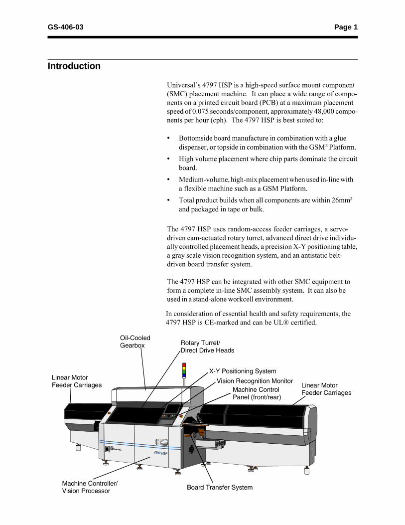
Universal�s 4797 HSP is a high-speed surface mount component(SMC) placement machine. It can place a wide range of compo-nents on a printed circuit board (PCB) at a maximum placementspeed of 0.075 seconds/component, approximately 48,000 compo-nents per hour (cph). The 4797 HSP is best suited to:
� Bottomside board manufacture in combination with a gluedispenser, or topside in combination with the GSM® Platform.
� High volume placement where chip parts dominate the circuitboard.
� Medium-volume, high-mix placement when used in-line witha flexible machine such as a GSM Platform.
� Total product builds when all components are within 26mm2
and packaged in tape or bulk.
The 4797 HSP uses random-access feeder carriages, a servo-driven cam-actuated rotary turret, advanced direct drive individu-ally controlled placement heads, a precision X-Y positioning table,a gray scale vision recognition system, and an antistatic belt-driven board transfer system.
The 4797 HSP can be integrated with other SMC equipment toform a complete in-line SMC assembly system. It can also beused in a stand-alone workcell environment.
In consideration of essential health and safety requirements, the4797 HSP is CE-marked and can be UL® certified.
Linear MotorFeeder Carriages
Oil-CooledGearbox Rotary Turret/
Direct Drive Heads
X-Y Positioning SystemVision Recognition Monitor
Machine ControlPanel (front/rear)
Linear MotorFeeder Carriages
Machine Controller/Vision Processor Board Transfer System
Page 2 GS-406-03
Functional Description
The 4797 HSP sequentially picks, visually recognizes, and placescomponents on a PCB. The actual placement sequence, how-ever, is fully programmable, depending upon user preference andcomponent pick/place requirements.
Typically, a PCB is presented to the machine X-Y positioningsystem by machine conveyors, where it is firmly located usingfront left-edge, topside registration. The actual location of art-work on the surface of the PCB is determined through the useof locator pins and/or recognition of board resident fiducials.
At the start of the component placement sequence, machine feedercarriages are moved into place under the rotary turret. Compo-nents are sequentially picked, visually recognized, and placed ac-cording to the indicated steps of the pattern program developedand inputted by the machine user.
At the conclusion of all placements steps, the PCB is moved ontothe machine output conveyors and transferred out onto externalconveyors and/or downline machines for further processing. Atthe same time this action is taking place, the next PCB is trans-ferred into the X-Y positioning system and the cycle continues.
Page 3GS-406-03
Standard Features
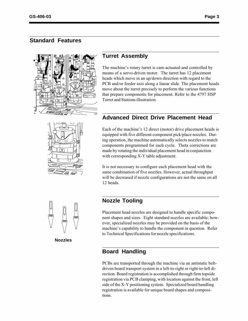
Turret Assembly
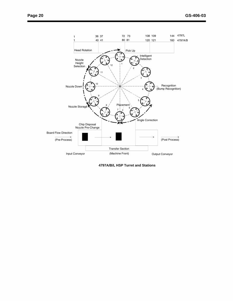
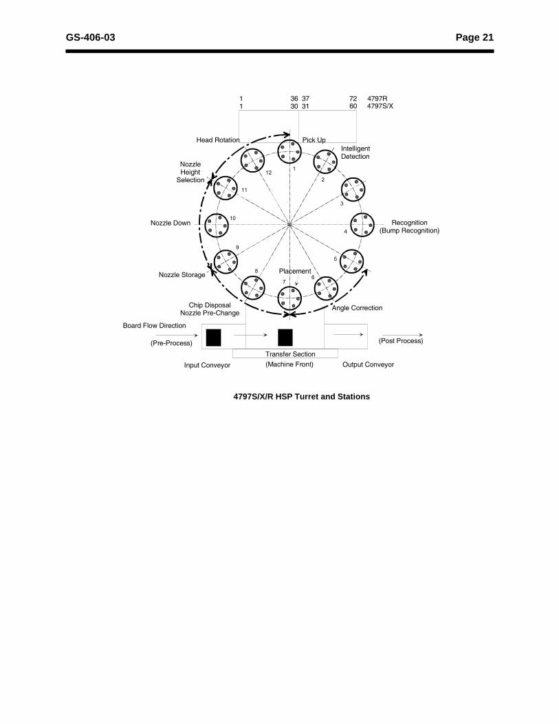
The machine�s rotary turret is cam-actuated and controlled bymeans of a servo-driven motor. The turret has 12 placementheads which move in an up/down direction with regard to thePCB and/or feeder axis along a linear slide. The placement headsmove about the turret precisely to perform the various functionsthat prepare components for placement. Refer to the 4797 HSPTurret and Stations illustration.
Advanced Direct Drive Placement Head
Each of the machine�s 12 direct (motor) drive placement heads isequipped with five different component pick/place nozzles. Dur-ing operation, the machine automatically selects nozzles to matchcomponents programmed for each cycle. Theta corrections aremade by rotating the individual placement head in conjunctionwith corresponding X-Y table adjustment.
It is not necessary to configure each placement head with thesame combination of five nozzles. However, actual throughputwill be decreased if nozzle configurations are not the same on all12 heads.
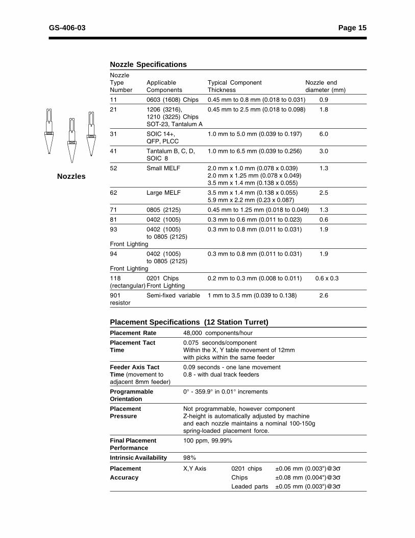
Nozzle Tooling
Placement head nozzles are designed to handle specific compo-nent shapes and sizes. Eight standard nozzles are available; how-ever, specialized nozzles may be provided on the basis of themachine�s capability to handle the component in question. Referto Technical Specifications for nozzle specifications.
Board Handling
PCBs are transported through the machine via an antistatic belt-driven board transport system in a left-to-right or right-to-left di-rection. Board registration is accomplished through firm topsideregistration via PCB clamping, with location against the front, leftside of the X-Y positioning system. Specialized board handlingregistration is available for unique board shapes and composi-tions.
Nozzles

Page 4 GS-406-03
Programmable Width Control
Input and output conveyor rails, as well as X-Y positioning sys-tem table rail width, is automatically adjusted when a new patternprogram is actuated.
Switchable Direction Board Transfer
Permits user to change direction of board transfer on the factoryfloor.
Auto Board Thickness
The distance between underside board support pins and the PCBis automatically adjusted when a new pattern program is acti-vated. Pin position and its relationship to the X-Y table grid ismanual.
Positioning System
The machine utilizes a precision X-Y table positioning system tolocate a PCB under the turret during placement steps. Both X-and Y-axis movements are controlled by AC servo-driven mo-tors.
Page 5GS-406-03
Vision Centering System
The 4797 HSP vision system provides contact-free componentrecognition and centering using either front or back lighting illumi-nation methods. The vision processor uses 256 level gray-scaleimage analysis to accurately locate the component and calculatethe appropriate X, Y, and theta adjustments.
High intensity fiber optic light is used to produce a sharp frontlitor backlit image, providing for precision placement and feederpick location (X and Y axis) updating. The image is captured byone of two high-resolution CCD cameras and optics (high andlow magnification) and processed by the machine vision control-ler. Largest applicable component is 26mm (1.024") square.*Optional on some models.
Fiducial Inspection
Fiducial inspection is used to register the PCB in the machine andcompensate for linear board distortions (stretch, shrink and non-orthogonality). Fiducial recognition may be selected for singleboards or individual boards in a breakaway.
The downward-looking P.E.C. (pattern error correction) fiducialinspection camera is mounted near the front of the turret. Thefield of view for this camera is approximately 12mm x 12mm(0.47" x 0.47"), with a window size of approximately 1mm(0.0394") square to 5mm (0.197") square. See the TechnicalSpecifications section for fiducial shapes, dimensions, and overallspecifications of this feature.
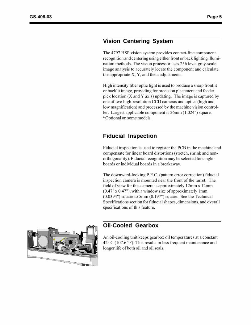
Oil-Cooled Gearbox
An oil-cooling unit keeps gearbox oil temperatures at a constant42° C (107.6 °F). This results in less frequent maintenance andlonger life of both oil and oil seals.
Page 6 GS-406-03
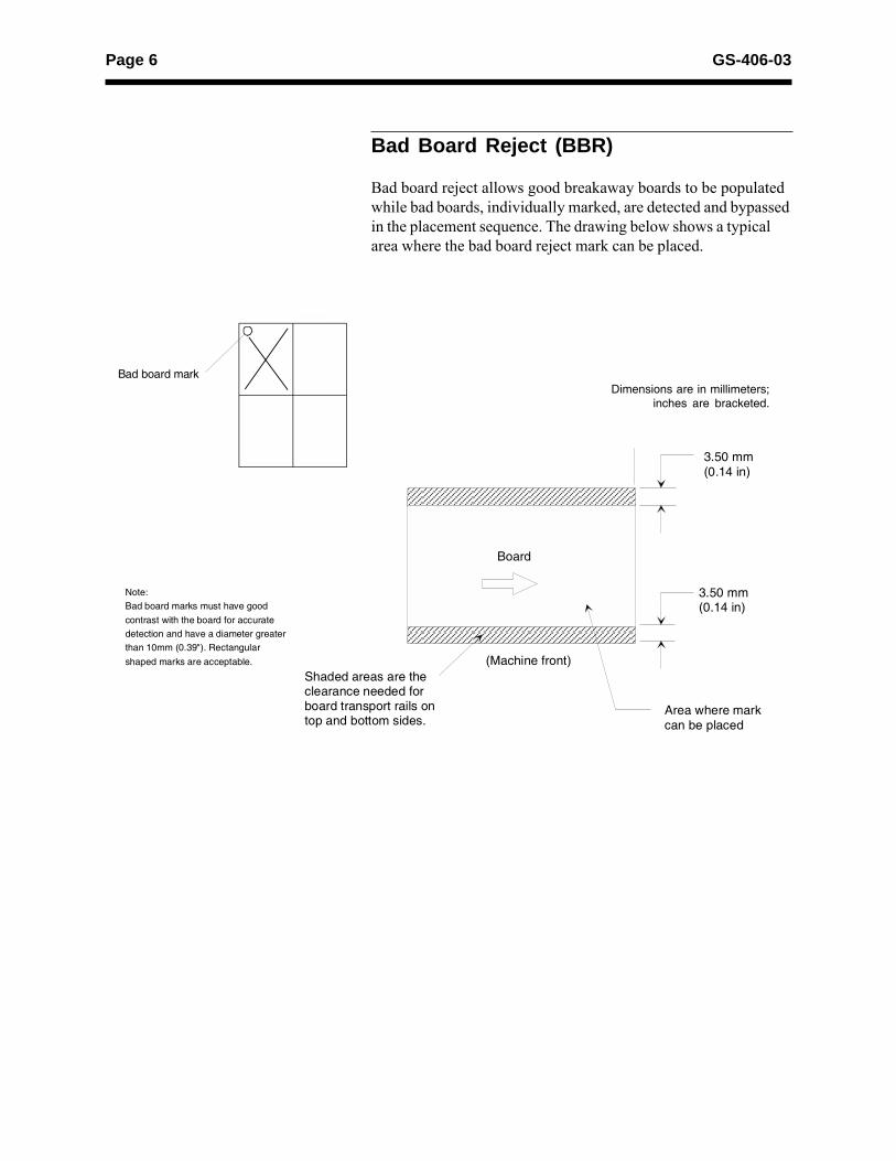
3.50 mm(0.14 in)
(Machine front)
Note:Bad board marks must have goodcontrast with the board for accuratedetection and have a diameter greaterthan 10mm (0.39"). Rectangularshaped marks are acceptable.
Shaded areas are theclearance needed forboard transport rails ontop and bottom sides.
Area where markcan be placed
Board
3.50 mm(0.14 in)
Dimensions are in millimeters;inches are bracketed.
Bad board mark
Bad Board Reject (BBR)
Bad board reject allows good breakaway boards to be populatedwhile bad boards, individually marked, are detected and bypassedin the placement sequence. The drawing below shows a typicalarea where the bad board reject mark can be placed.
Page 7GS-406-03
Random Access Feeder Carriage System
The feeder delivery system consists of four (or two) random ac-cess feeder carriages located in the rear of the machine. Eachfeeder carriage is automatically controlled by the machine andpattern program. See the Technical Specifications section for in-formation regarding feeder capacity.
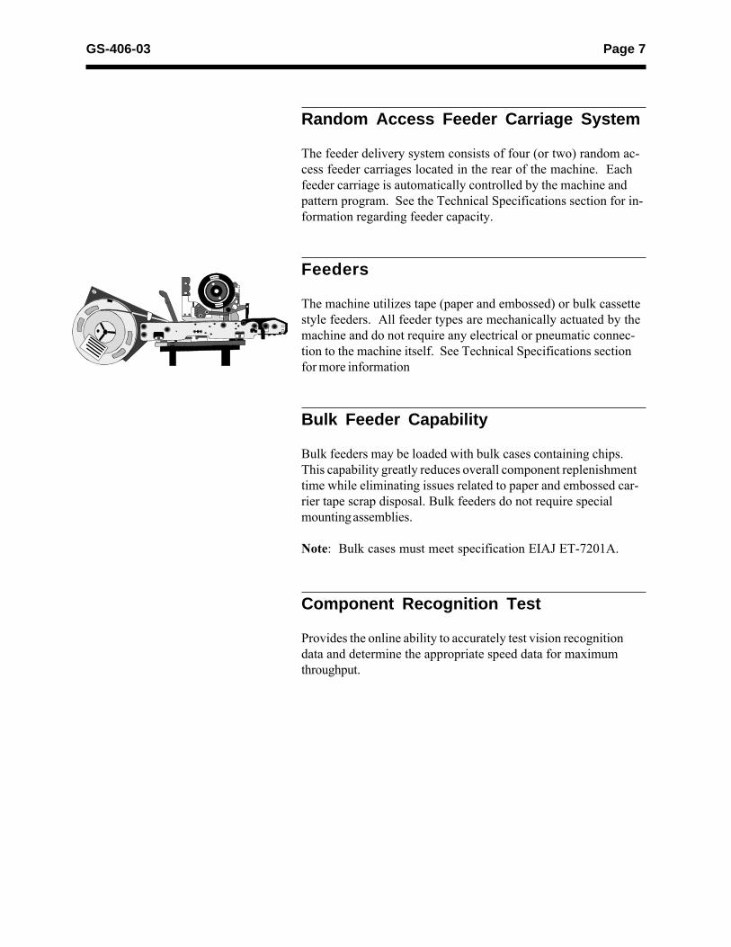
Feeders
The machine utilizes tape (paper and embossed) or bulk cassettestyle feeders. All feeder types are mechanically actuated by themachine and do not require any electrical or pneumatic connec-tion to the machine itself. See Technical Specifications sectionfor more information
Bulk Feeder Capability
Bulk feeders may be loaded with bulk cases containing chips.This capability greatly reduces overall component replenishmenttime while eliminating issues related to paper and embossed car-rier tape scrap disposal. Bulk feeders do not require specialmounting assemblies.
Note: Bulk cases must meet specification EIAJ ET-7201A.
Component Recognition Test
Provides the online ability to accurately test vision recognitiondata and determine the appropriate speed data for maximumthroughput.
Page 8 GS-406-03
Pattern Programming
Pattern programs may be generated off-line using one of fivemethods:
� Utilizing manual keyboard entry on a personal computerloaded with WINDOWS 2000® -based UCT 53 software.(UCT 53 is provided free-of-charge with each machine.)
� Utilizing Universal�s Dimensions� programming and optimi-zation software (DPO). DPO software provides one point ofdata entry, a common interface across machine types, and aconsistent process to generate production and setup data forone of more assembly lines, with any combination of GSMplatforms and HSP machines or for single machines.
Pattern programs may be generated for individual boards orbreakaway boards with up to 500 pattern offsets.
UCT 53 Software
In addition to providing pattern creation capability and optimiza-tion, UCT 53 software also provides the ability to communicatebetween the machine and the pattern programs, managementdata, and device data. Data may be transferred between each bya local area network (LAN) connection.
UCT 53 software also contains a component library databasecontaining parameters for each component used in the vision rec-ognition and placement process. Entries in the component librarymay be copied, edited, and transferred between the machine andoff-line component library. ID names may coincide with user�sinternal part numbers.
UCT 53 is available in either English or Chinese languages. Bothrequire Windows 2000TM operating systems.
Page 9GS-406-03
Program and Data Storage
Active machine memory stores up to 500 pattern programs or20K placement/offset steps per pattern program. Additional pat-tern program and component library storage is available with theoff-line personal computer.
Control System and Machine Software
The control system and machine software regulate machine op-erations using a 68,000-based microprocessor with VME bus ar-chitecture. The machine control software initiates, monitors, andreports operations through the touch screen machine controlpanel (MCP) interface, keyboard, trackball, joystick, and visionsystem monitor.
The operating system is Windows 2000TM, and is available in ei-ther English or Chinese.
Hard Disk Drive (HDD)Floppy Disk Drive (FDD)Component Disk Drive (CDD)
The machine is provided with an FDD and/or CDD, and the ma-chine data can be loaded from or saved on to a disk.• The device, management, pattern program, and component
library data can be saved from the machine side to a diskand later reloaded into the machine.
• All back-up data can be saved from the machine side todisk.
Page 10 GS-406-03
Optional FeaturesNote: For options or applications not listed, please contact theHSP RFQ Gatekeeper through your Universal Sales Engineer.
Pattern Program Coordinate Teaching
Pattern program coordinate and offset data (component and fidu-cial locations) can be taught using the machine�s downward-look-ing camera.
Component Library Data Teaching
Vision recognition data, pertinent to a given component, can betaught using a component, picked by or placed on a nozzle, themachine�s vision recognition camera system, and a trackball.
Generic Equipment Model Interface (GEM)
GEM provides an industry standard machine communication pro-tocol over a TCP-IP based network. GEM compliance is basedon SEMI International Standard E30-93.
Barcode Validation System (BVS)
The Barcode Validation System is used to insure that the feederset-up is correct prior to the start of a production run. Duringfeeder set-up, which is performed off-line, barcode data isscanned from the component reels and simultaneously written tomemory tags located in each feeder handle. After the feedersare loaded on the machine, the BVS system reads the storedfeeder handle data while the feeder carriages are being trans-ferred to the pick area. Production is allowed to occur only afterBVS verifies that each component feeder is in the correct loca-tion, according to the active pattern program.
Page 11GS-406-03
Barcode Product Change
When a specific barcode is put on the P.C.B., this functionmakes it possible for the machine to automatically perform theprogram change during automatic operation according to the re-sults of the barcode reading. As a result, the time for programchange and set-up operations can be reduced.
Dimensions Programming andOptimization
Dimensions Programming and Optimization (DPO) software pro-vides one point of data entry, a common interface acrossmachine types, and a consistent process to generate productionand set-up data for one or more assembly lines, with any combi-nation of GSM Platforms and HSP Machines or for single ma-chines. It also offers sharing of component and feeder informa-tion across multiple DPO systems.
The DPO software is an independent application and can be inte-grated with other products in the Dimensions Manufacturing Au-tomation Software suite. Dimensions Programming and Optimiza-tion Software provides a single programming and line optimizationprocess for Universal surface mount assembly lines.
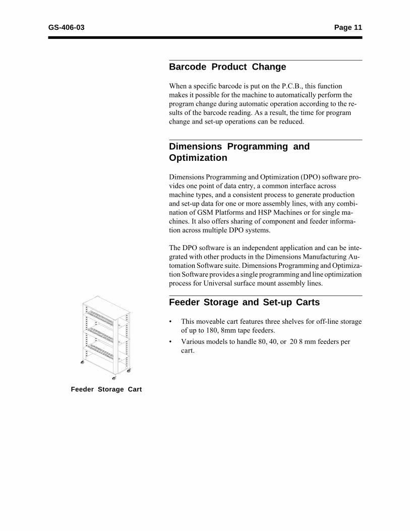
Feeder Storage and Set-up Carts
� This moveable cart features three shelves for off-line storageof up to 180, 8mm tape feeders.
� Various models to handle 80, 40, or 20 8 mm feeders percart.
Feeder Storage Cart
Page 12 GS-406-03
Power Transformer
This transformer allows for conversion of input power betweenindividual machines within a system.
Ceramic Applications
These substrates may require special anti-wear components andmay require fiducial blacklighting or backlighting. Consult theHSP RFQ Gatekeeper through your Universal Sales Engineer.
Feeder Reload Tool
This free standing fixture may be placed on any flat surface. Itis used to aid in the replenishment of empty feeders by holdingthe feeder securely while new component reels are mounted.
Applied Conveyor Engineering®
Conveyors
A variety of configurations and styles of conveyor systems areavailable to perform required system functions.
Page 13GS-406-03
GS-256 Quality Assurance Terms and ApplicationsStandards, Series 0000
GS-283 Standard Machine Parallel Interface (SMPI)Board Processing Protocol (BPP), Series8000
GS-284 Standard Machine Parallel Interface(SMPI), Series 6000
GS-356 UniScan Machine Programming Station,Model 86741
EIAJ EIA Standard for Taping Surface MountComponents for Automatic Placement. (Ja-pan Issue)
EIA-481 EIA Standard for Taping Surface MountComponents for Automatic Placement
JIS CO806-1990 Embossed Carrier Taping StandardQAP4791A Quality Assurance CriteriaSMEMA Standards 1.1(Interface) and 3.1(Fiducial
Mark)SEMI E30-93
Supporting Documents
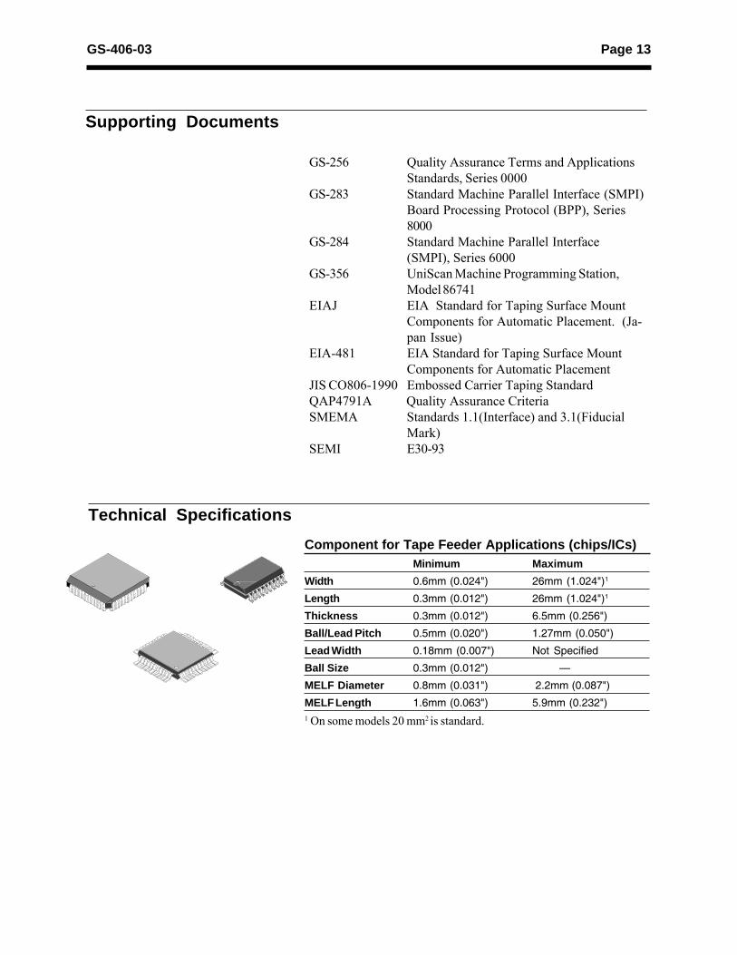
Minimum MaximumWidth 0.6mm (0.024") 26mm (1.024")1
Length 0.3mm (0.012") 26mm (1.024")1
Thickness 0.3mm (0.012") 6.5mm (0.256")
Ball/Lead Pitch 0.5mm (0.020") 1.27mm (0.050")
Lead Width 0.18mm (0.007") Not Specified
Ball Size 0.3mm (0.012") �
MELF Diameter 0.8mm (0.031") 2.2mm (0.087")
MELF Length 1.6mm (0.063") 5.9mm (0.232")1 On some models 20 mm2 is standard.
Technical Specifications
Component for Tape Feeder Applications (chips/ICs)
Page 14 GS-406-03
L
T
WWL
T
T
LT
WW
L
T
WL
L
W
T
L
W (Dia)LW
TT
W L
T
L W
WLW
T
L
T
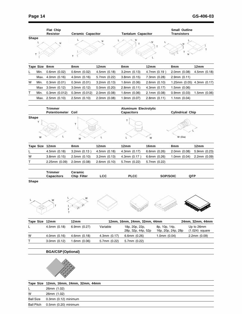
Tape Size 12mm 12mm 12mm, 16mm, 24mm, 32mm, 44mm 24mm, 32mm, 44mm
L 4.5mm (0.18) 6.9mm (0.27) Variable 18p, 20p, 22p, 8p, 10p, 14p, Up to 26mm28p, 32p, 44p, 52p 16p, 20p, 24p, 28p (1.024) square
W 4.0mm (0.16) 4.6mm (0.18) 4.3mm (0.17) 6.6mm (0.26) 1.0mm (0.04) 2.2mm (0.09)
T 3.0mm (0.12) 1.6mm (0.06) 5.7mm (0.22) 5.7mm (0.22)
BGA/CSP (Optional)
Tape Size 12mm, 16mm, 24mm, 32mm, 44mm
L 26mm (1.02)
W 26mm (1.02)
Ball Size 0.3mm (0.12) minimum
Ball Pitch 0.5mm (0.20) minimum
Shape
Tape Size 8mm 8mm 12mm 8mm 12mm 8mm 12mm
L Min. 0.6mm (0.02) 0.6mm (0.02) 4.5mm (0.18) 3.2mm (0.13) 4.7mm (0.19 ) 2.0mm (0.08) 4.5mm (0.18)
Max. 4.0mm (0.16) 4.0mm (0.16) 5.7mm (0.22) 3.8mm (0.15) 7.3mm (0.28) 2.9mm (0.11)
W Min. 0.3mm (0.01) 0.3mm (0.01) 3.2mm (0.13) 1.6mm (0.06) 2.6mm (0.10) 1.25mm (0.05) 4.3mm (0.17)
Max 3.0mm (0.12) 3.0mm (0.12) 5.0mm (0.20) 2.8mm (0.11) 4.3mm (0.17) 1.5mm (0.06)
T Min. 0.3mm (0.012) 0.3mm (0.012) 2.0mm (0.08) 1.6mm (0.06) 2.1mm (0.08) 0.9mm (0.03) 1.5mm (0.06)
Max. 2.5mm (0.10) 2.5mm (0.10) 2.0mm (0.08) 1.9mm (0.07) 2.8mm (0.11) 1.1mm (0.04)
Trimmer Aluminum ElectrolyticPotentiometer Coil Capacitors Cylindrical Chip
Shape
Tape Size 12mm 8mm 12mm 12mm 16mm 8mm 12mm
L 4.5mm (0.18) 3.2mm (0.13 ) 4.5mm (0.18) 4.3mm (0.17) 6.6mm (0.26) 2.0mm (0.08) 5.9mm (0.23)
W 3.8mm (0.15) 2.5mm (0.10) 3.2mm (0.13) 4.3mm (0.17 ) 6.6mm (0.26) 1.0mm (0.04) 2.2mm (0.09)
T 2.25mm (0.09) 2.0mm (0.08) 2.6mm (0.10) 5.7mm (0.22) 5.7mm (0.22)
Trimmer CeramicCapacitors Chip Filter LCC PLCC SOP/SOIC QFP
Shape
Flat Chip Small OutlineResistor Ceramic Capacitor Tantalum Capacitor Transistors
Page 15GS-406-03
Nozzle SpecificationsNozzleType Applicable Typical Component Nozzle endNumber Components Thickness diameter (mm)
11 0603 (1608) Chips 0.45 mm to 0.8 mm (0.018 to 0.031) 0.9
21 1206 (3216), 0.45 mm to 2.5 mm (0.018 to 0.098) 1.81210 (3225) ChipsSOT-23, Tantalum A
31 SOIC 14+, 1.0 mm to 5.0 mm (0.039 to 0.197) 6.0QFP, PLCC
41 Tantalum B, C, D, 1.0 mm to 6.5 mm (0.039 to 0.256) 3.0SOIC 8
52 Small MELF 2.0 mm x 1.0 mm (0.078 x 0.039) 1.32.0 mm x 1.25 mm (0.078 x 0.049)3.5 mm x 1.4 mm (0.138 x 0.055)
62 Large MELF 3.5 mm x 1.4 mm (0.138 x 0.055) 2.55.9 mm x 2.2 mm (0.23 x 0.087)
71 0805 (2125) 0.45 mm to 1.25 mm (0.018 to 0.049) 1.3
81 0402 (1005) 0.3 mm to 0.6 mm (0.011 to 0.023) 0.6
93 0402 (1005) 0.3 mm to 0.8 mm (0.011 to 0.031) 1.9to 0805 (2125)
Front Lighting
94 0402 (1005) 0.3 mm to 0.8 mm (0.011 to 0.031) 1.9to 0805 (2125)
Front Lighting
118 0201 Chips 0.2 mm to 0.3 mm (0.008 to 0.011) 0.6 x 0.3(rectangular) Front Lighting
901 Semi-fixed variable 1 mm to 3.5 mm (0.039 to 0.138) 2.6resistor
Placement Specifications (12 Station Turret)Placement Rate 48,000 components/hour
Placement Tact 0.075 seconds/componentTime Within the X, Y table movement of 12mm
with picks within the same feeder
Feeder Axis Tact 0.09 seconds - one lane movementTime (movement to 0.8 - with dual track feedersadjacent 8mm feeder)
Programmable 0° - 359.9° in 0.01° incrementsOrientationPlacement Not programmable, however componentPressure Z-height is automatically adjusted by machine
and each nozzle maintains a nominal 100-150gspring-loaded placement force.
Final Placement 100 ppm, 99.99%PerformanceIntrinsic Availability 98%
Placement X,Y Axis 0201 chips ±0.06 mm (0.003")@3σAccuracy Chips ±0.08 mm (0.004")@3σ
Leaded parts ±0.05 mm (0.003")@3σ
Nozzles
Page 16 GS-406-03
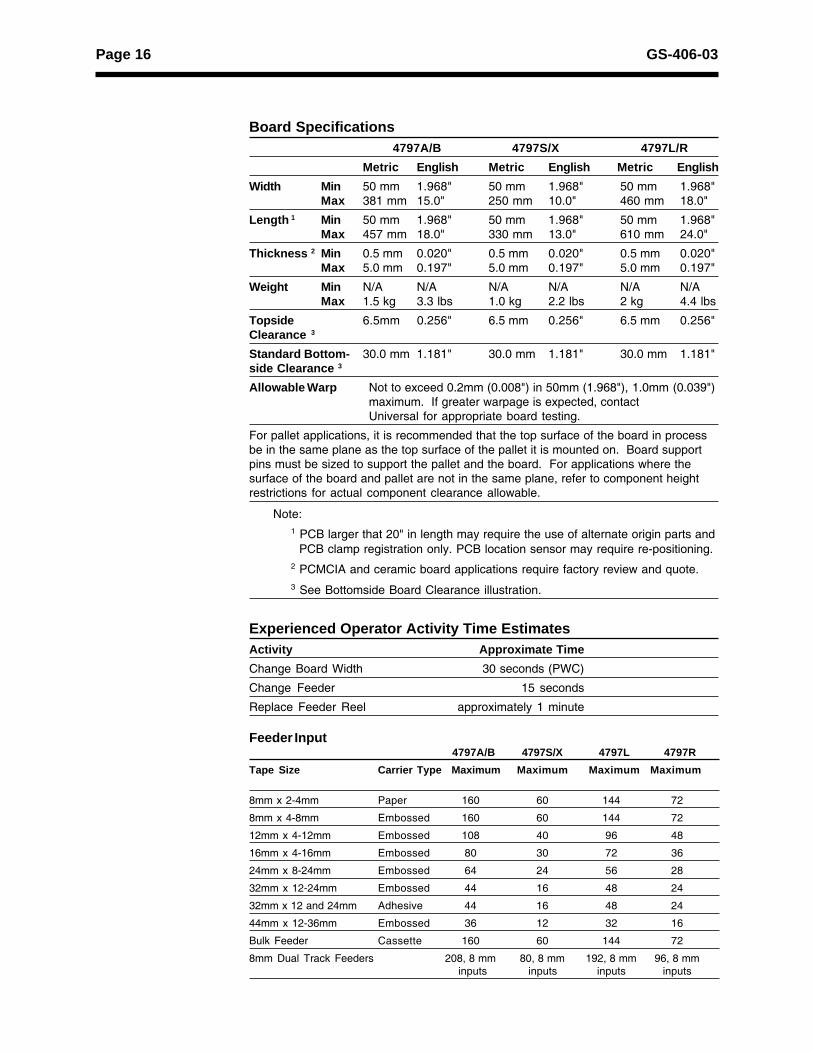
Feeder Input4797A/B 4797S/X 4797L 4797R
Tape Size Carrier Type Maximum Maximum Maximum Maximum
8mm x 2-4mm Paper 160 60 144 72
8mm x 4-8mm Embossed 160 60 144 72
12mm x 4-12mm Embossed 108 40 96 48
16mm x 4-16mm Embossed 80 30 72 36
24mm x 8-24mm Embossed 64 24 56 28
32mm x 12-24mm Embossed 44 16 48 24
32mm x 12 and 24mm Adhesive 44 16 48 24
44mm x 12-36mm Embossed 36 12 32 16
Bulk Feeder Cassette 160 60 144 72
8mm Dual Track Feeders 208, 8 mm 80, 8 mm 192, 8 mm 96, 8 mm inputs inputs inputs inputs
Board Specifications4797A/B 4797S/X 4797L/R
Metric English Metric English Metric EnglishWidth Min 50 mm 1.968" 50 mm 1.968" 50 mm 1.968"
Max 381 mm 15.0" 250 mm 10.0" 460 mm 18.0"
Length 1 Min 50 mm 1.968" 50 mm 1.968" 50 mm 1.968"Max 457 mm 18.0" 330 mm 13.0" 610 mm 24.0"
Thickness 2 Min 0.5 mm 0.020" 0.5 mm 0.020" 0.5 mm 0.020"Max 5.0 mm 0.197" 5.0 mm 0.197" 5.0 mm 0.197"
Weight Min N/A N/A N/A N/A N/A N/AMax 1.5 kg 3.3 lbs 1.0 kg 2.2 lbs 2 kg 4.4 lbs
Topside 6.5mm 0.256" 6.5 mm 0.256" 6.5 mm 0.256"Clearance 3
Standard Bottom- 30.0 mm 1.181" 30.0 mm 1.181" 30.0 mm 1.181"side Clearance 3
Allowable Warp Not to exceed 0.2mm (0.008") in 50mm (1.968"), 1.0mm (0.039")maximum. If greater warpage is expected, contactUniversal for appropriate board testing.
For pallet applications, it is recommended that the top surface of the board in processbe in the same plane as the top surface of the pallet it is mounted on. Board supportpins must be sized to support the pallet and the board. For applications where thesurface of the board and pallet are not in the same plane, refer to component heightrestrictions for actual component clearance allowable.
Note:1 PCB larger that 20" in length may require the use of alternate origin parts and PCB clamp registration only. PCB location sensor may require re-positioning.2 PCMCIA and ceramic board applications require factory review and quote.3 See Bottomside Board Clearance illustration.
Experienced Operator Activity Time EstimatesActivity Approximate TimeChange Board Width 30 seconds (PWC)
Change Feeder 15 seconds
Replace Feeder Reel approximately 1 minute
Page 17GS-406-03
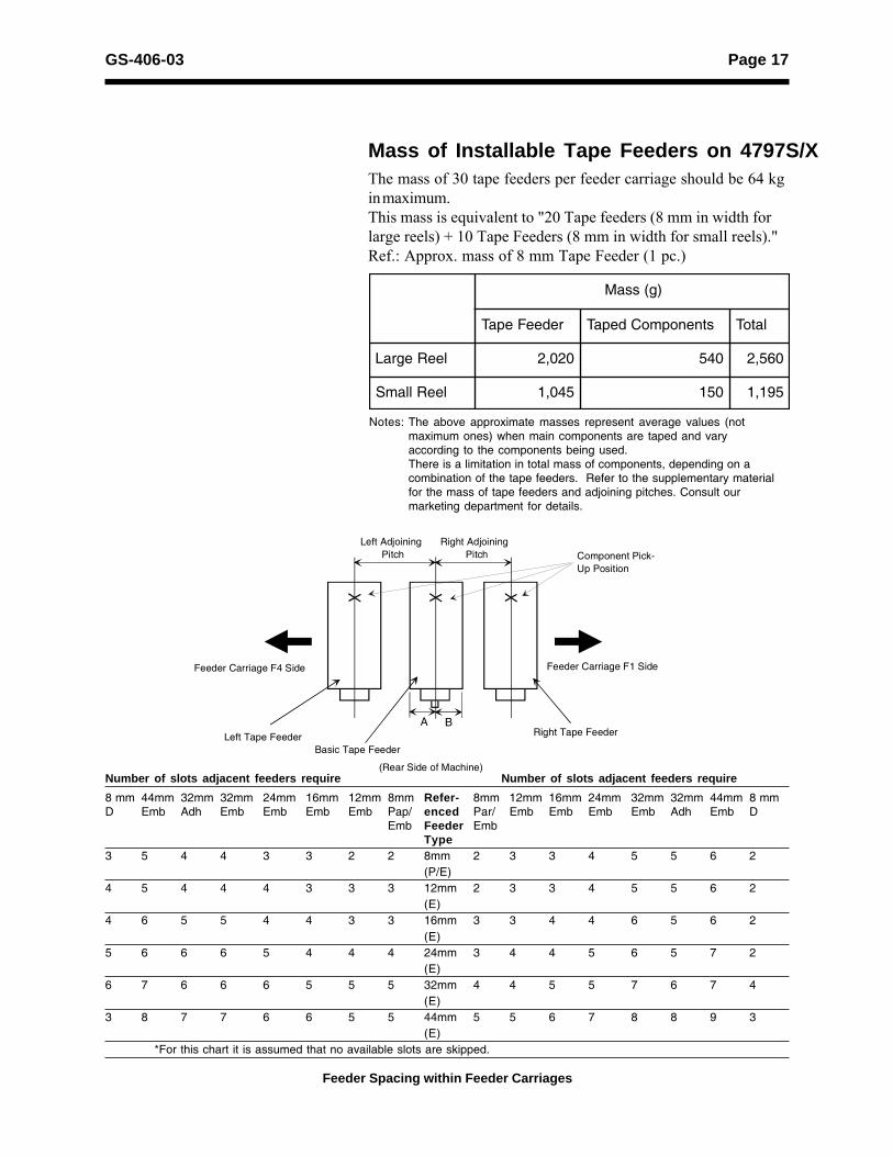
Number of slots adjacent feeders require Number of slots adjacent feeders require
8 mm 44mm 32mm 32mm 24mm 16mm 12mm 8mm Refer- 8mm 12mm 16mm 24mm 32mm 32mm 44mm 8 mmD Emb Adh Emb Emb Emb Emb Pap/ enced Par/ Emb Emb Emb Emb Adh Emb D
Emb Feeder EmbType
3 5 4 4 3 3 2 2 8mm 2 3 3 4 5 5 6 2(P/E)
4 5 4 4 4 3 3 3 12mm 2 3 3 4 5 5 6 2(E)
4 6 5 5 4 4 3 3 16mm 3 3 4 4 6 5 6 2(E)
5 6 6 6 5 4 4 4 24mm 3 4 4 5 6 5 7 2(E)
6 7 6 6 6 5 5 5 32mm 4 4 5 5 7 6 7 4(E)
3 8 7 7 6 6 5 5 44mm 5 5 6 7 8 8 9 3(E)
*For this chart it is assumed that no available slots are skipped.
Feeder Spacing within Feeder Carriages
Mass of Installable Tape Feeders on 4797S/XThe mass of 30 tape feeders per feeder carriage should be 64 kgin maximum.This mass is equivalent to "20 Tape feeders (8 mm in width forlarge reels) + 10 Tape Feeders (8 mm in width for small reels)."Ref.: Approx. mass of 8 mm Tape Feeder (1 pc.)
)g(ssaM
redeeFepaT stnenopmoCdepaT latoT
leeRegraL 020,2 045 065,2
leeRllamS 540,1 051 591,1
Notes: The above approximate masses represent average values (notmaximum ones) when main components are taped and varyaccording to the components being used.There is a limitation in total mass of components, depending on acombination of the tape feeders. Refer to the supplementary materialfor the mass of tape feeders and adjoining pitches. Consult ourmarketing department for details.
(Rear Side of Machine)
Feeder Carriage F4 Side Feeder Carriage F1 Side
A BRight Tape FeederLeft Tape Feeder
Basic Tape Feeder
Component Pick-Up Position
Left AdjoiningPitch
Right AdjoiningPitch
Page 18 GS-406-03
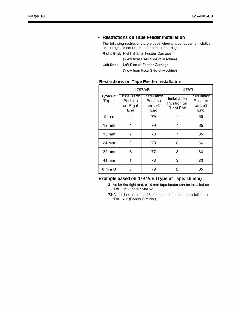
• Restrictions on Tape Feeder InstallationThe following restrictions are placed when a tape feeder is installedon the right or the left end of the feeder carriage.
Right End: Right Side of Feeder Carriage
(View from Rear Side of Machine)
Left End: Left Side of Feeder Carriage
(View from Rear Side of Machine)
Types ofTapes
4797A/B 4797L
InstallationPositionon Right
End
InstallationPositionon Left
End
InstallationPosition onRight End
InstallationPositionon Left
End
8 mm 1 79 1 35
12 mm 1 79 1 35
16 mm 2 78 1 35
24 mm 2 78 2 34
32 mm 3 77 3 33
44 mm 4 76 3 33
8 mm D 2 79 2 35
Restrictions on Tape Feeder Installation
Example based on 4797A/B (Type of Tape: 16 mm)2: As for the right end, a 16 mm tape feeder can be installed on
"Fdr. **2" (Feeder Slot No.)
78:As for the left end, a 16 mm tape feeder can be installed on"Fdr. *78" (Feeder Slot No.).

Page 19GS-406-03
Board Handling Available
Yes NoBoard Registration PCB clamping X
Top edge register XFront edge register XTooling pin XVision (P.E.C.) X
Board Transfer Left-to-right XDirection Switchable right-to-left/
left-to-right XTransfer Height 962.2+3.0mm 37.88+0.12" SMEMA
-22.4mm -0.88"
Board Transfer Time approximately 2.5 - 4.0 seconds, including tablemovement (time between final placement ofprevious PCB and placement start of followingPCB). Belt speed is programmable. Undercertain process conditions, transfer speed maybe adjusted.
Note: SMEMA communication to upline/downline equipment is standard.
Page 20 GS-406-03
4797A/B/L HSP Turret and Stations
Recognition(Bump Recognition)
Pick Up
IntelligentDetection
1
2
3
4
5
67
8
9
10
11
12
Angle CorrectionChip Disposal
Nozzle Pre-Change
Nozzle Storage
Nozzle Down
Nozzle Height
Selection
Head Rotation
Transfer Section
(Post Process)
Output Conveyor(Machine Front)Input Conveyor
Board Flow Direction
(Pre-Process)
Placement
4797L
4797A/B1 40 41 80 81 120 121 1601 36 37 72 73 108 109 144
Page 21GS-406-03
4797S/X/R HSP Turret and Stations
Recognition(Bump Recognition)
Pick UpIntelligentDetection
1
2
3
4
5
67
8
9
10
11
12
Angle CorrectionChip DisposalNozzle Pre-Change
Nozzle Storage
Nozzle Down
Nozzle Height
Selection
Head Rotation
1 30 31 60
(Post Process)
Output ConveyorTransfer Section(Machine Front)Input Conveyor
(Pre-Process)
Board Flow Direction
Placement
4797S/X1 36 37 72 4797R
Page 22 GS-406-03
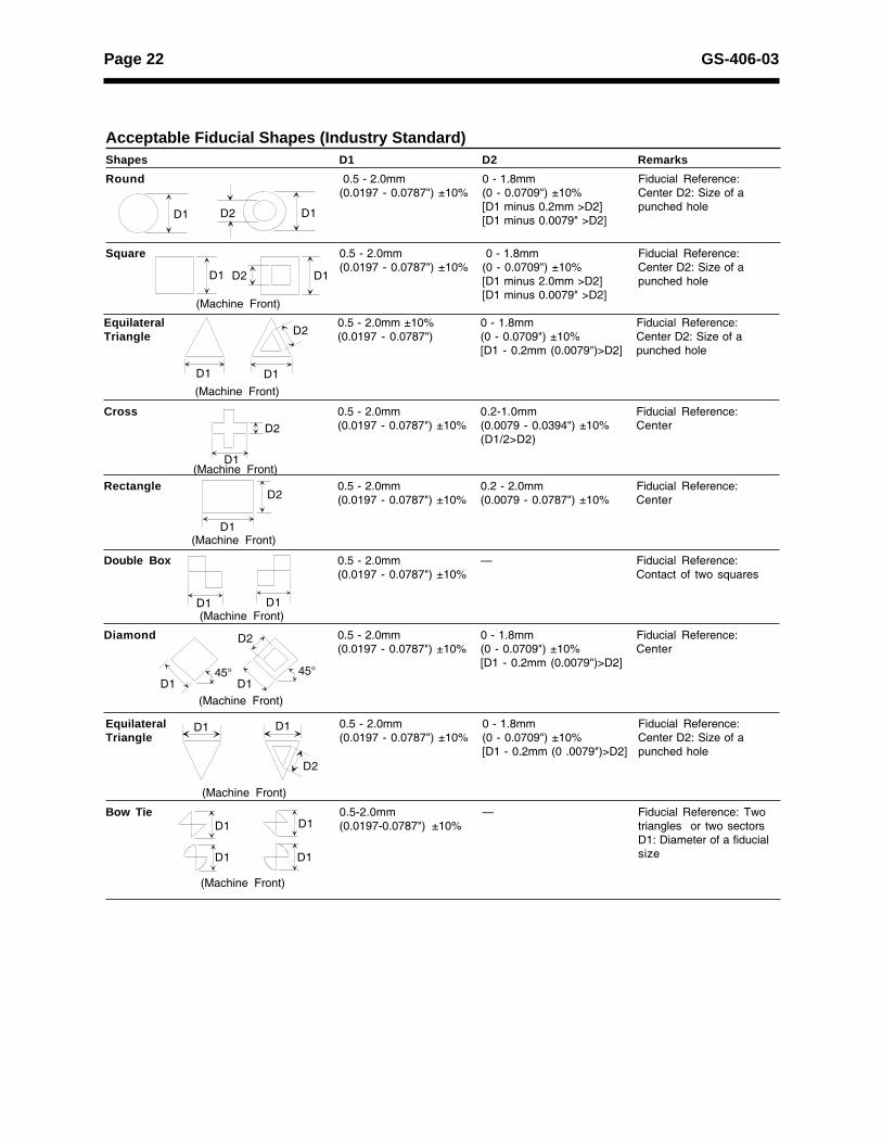
Acceptable Fiducial Shapes (Industry Standard)Shapes D1 D2 Remarks
Round 0.5 - 2.0mm 0 - 1.8mm Fiducial Reference:(0.0197 - 0.0787") ±10% (0 - 0.0709") ±10% Center D2: Size of a
[D1 minus 0.2mm >D2] punched hole[D1 minus 0.0079" >D2]
Square 0.5 - 2.0mm 0 - 1.8mm Fiducial Reference:(0.0197 - 0.0787") ±10% (0 - 0.0709") ±10% Center D2: Size of a
[D1 minus 2.0mm >D2] punched hole[D1 minus 0.0079" >D2]
Equilateral 0.5 - 2.0mm 0 - 1.8mm Fiducial Reference:Triangle (0.0197 - 0.0787") ±10% (0 - 0.0709") ±10% Center D2: Size of a
[D1 - 0.2mm (0 .0079")>D2] punched hole
Bow Tie 0.5-2.0mm � Fiducial Reference: Two(0.0197-0.0787") ±10% triangles or two sectors
D1: Diameter of a fiducialsize
D1D2D1
D1D1 D2
(Machine Front)
D2
D1 D1(Machine Front)
(Machine Front)D1
D2
(Machine Front)
D2
D1
(Machine Front)D1D1
(Machine Front)
D2
D1 D145° 45°
(Machine Front)
D2
D1 D1
(Machine Front)
D1 D1
D1D1
Equilateral 0.5 - 2.0mm ±10% 0 - 1.8mm Fiducial Reference:Triangle (0.0197 - 0.0787") (0 - 0.0709") ±10% Center D2: Size of a
[D1 - 0.2mm (0.0079")>D2] punched hole
Cross 0.5 - 2.0mm 0.2-1.0mm Fiducial Reference:(0.0197 - 0.0787") ±10% (0.0079 - 0.0394") ±10% Center
(D1/2>D2)
Rectangle 0.5 - 2.0mm 0.2 - 2.0mm Fiducial Reference:(0.0197 - 0.0787") ±10% (0.0079 - 0.0787") ±10% Center
Double Box 0.5 - 2.0mm � Fiducial Reference:(0.0197 - 0.0787") ±10% Contact of two squares
Diamond 0.5 - 2.0mm 0 - 1.8mm Fiducial Reference:(0.0197 - 0.0787") ±10% (0 - 0.0709") ±10% Center
[D1 - 0.2mm (0.0079")>D2]
Page 23GS-406-03
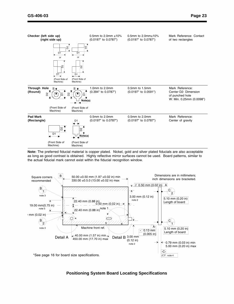
Positioning System Board Locating Specifications
Dimensions are in millimeters;inch dimensions are bracketed.
*See page 16 for board size specifications.
B1
B2
22.40 mm (0.88 in)
22.40 mm (0.88 in)
C2
C1
5.10 mm (0.20 in)Length of board
0.79 mm (0.03 in) min5.00 mm (0.20 in) max
-C-
Detail BDetail A
Machine front ref.
0.50 mm (0.02 in)note 1
50.00 ±0.50 mm (1.97 ±0.02 in) min330.00 ±0.5.0 (13.00 ±0.02 in) max
Square cornersrecommended
note 3
note 3
0 mm (0.02 in)
40.00 mm (1.57 in) min450.00 mm (17.70 in) max
B
note 5
// 0.50 mm (0.02 in) A
A- - 0.13 mm (0.005 in)
note 2
19.00 mm(0.75 in)
3.00 mm(0.12 in)
note 23.00 mm (0.12 in)
5.10 mm (0.20 in)Length of board
note 4
Through Hole 1.0mm to 2.0mm 0.5mm to 1.5mm Mark Reference:(Round) (0.394" to 0.0787") (0.0197" to 0.0591") Center D2: Dimension
of punched holeW: Min. 0.25mm (0.0098")
Pad Mark 0.5mm to 2.0mm 0.5mm to 2.0mm Mark Reference:(Rectangle) (0.0197" to 0.0787") (0.0197" to 0.0787") Center of gravity
Checker (left side up) 0.5mm to 2.0mm ±10% 0.5mm to 2.0mm±10% Mark Reference: Contact (right side up) (0.0197" to 0.0787") (0.0197" to 0.0787") of two rectangles
Note: The preferred fiducial material is copper plated. Nickel, gold and silver plated fiducials are also acceptableas long as good contrast is obtained. Highly reflective mirror surfaces cannot be used. Board patterns, similar tothe actual fiducial mark cannot exist within the fiducial recognition window.
D1
D2
or
D2
D1
(Front Side ofMachine)
or
(Front Side ofMachine)
D2
D1
D1
D2
D2
D1
(Front Side ofMachine)
(Front Side ofMachine)
Note(a)
W
D2
D1
W
D1
(Front Side ofMachine)
(Front Side ofMachine)
D2
D1
D2
Note(a)
Page 24 GS-406-03
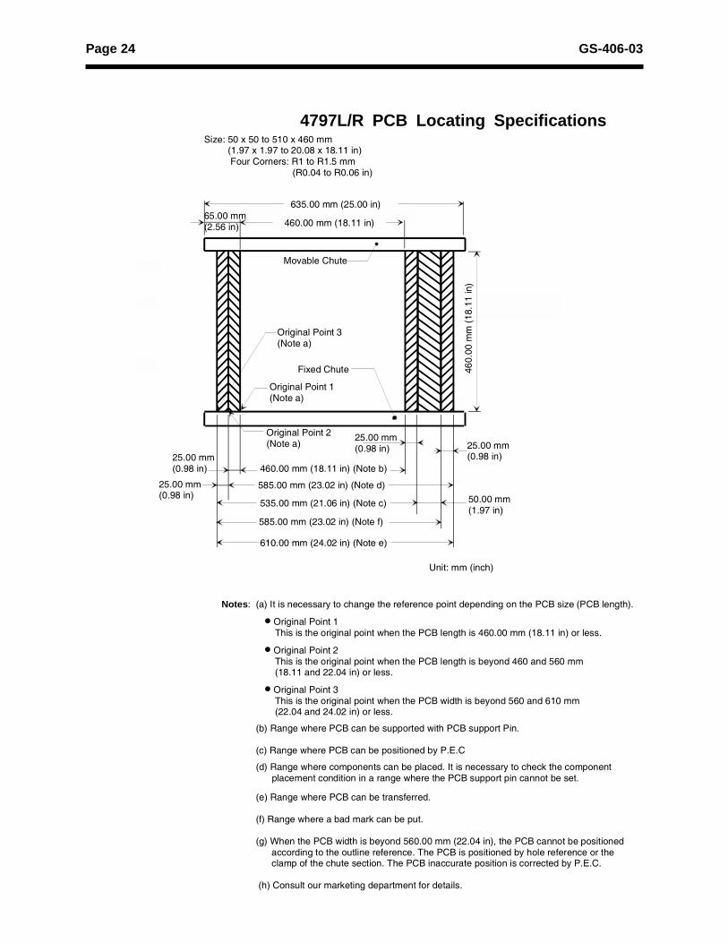
4797L/R PCB Locating Specifications
Size: 50 x 50 to 510 x 460 mm (1.97 x 1.97 to 20.08 x 18.11 in) Four Corners: R1 to R1.5 mm (R0.04 to R0.06 in)
65.00 mm(2.56 in)
Movable Chute
Original Point 3(Note a)
Fixed Chute
Original Point 1(Note a)
Original Point 2(Note a)
25.00 mm(0.98 in)
25.00 mm(0.98 in)
25.00 mm(0.98 in)
25.00 mm(0.98 in)
50.00 mm(1.97 in)
460.
00 m
m (1
8.11
in)
Unit: mm (inch)
Notes: (a) It is necessary to change the reference point depending on the PCB size (PCB length).
• Original Point 1 This is the original point when the PCB length is 460.00 mm (18.11 in) or less.
• Original Point 2 This is the original point when the PCB length is beyond 460 and 560 mm (18.11 and 22.04 in) or less.
• Original Point 3 This is the original point when the PCB width is beyond 560 and 610 mm (22.04 and 24.02 in) or less.
(b) Range where PCB can be supported with PCB support Pin.
(c) Range where PCB can be positioned by P.E.C
(d) Range where components can be placed. It is necessary to check the component placement condition in a range where the PCB support pin cannot be set.
(e) Range where PCB can be transferred. (f) Range where a bad mark can be put.
(g) When the PCB width is beyond 560.00 mm (22.04 in), the PCB cannot be positioned according to the outline reference. The PCB is positioned by hole reference or the clamp of the chute section. The PCB inaccurate position is corrected by P.E.C.
(h) Consult our marketing department for details.
635.00 mm (25.00 in)
460.00 mm (18.11 in)
460.00 mm (18.11 in) (Note b)
585.00 mm (23.02 in) (Note d)
535.00 mm (21.06 in) (Note c)
610.00 mm (24.02 in) (Note e)
585.00 mm (23.02 in) (Note f)
Page 25GS-406-03
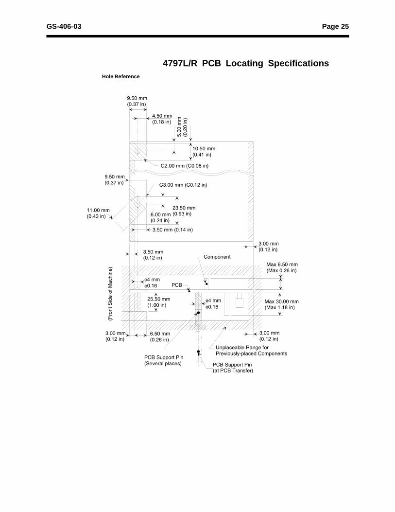
Hole Reference
9.50 mm(0.37 in)
4.50 mm(0.18 in)
5.00
mm
(0.2
0 in
)
10.50 mm(0.41 in)
C2.00 mm (C0.08 in)
C3.00 mm (C0.12 in)
6.00 mm(0.24 in)
23.50 mm(0.93 in)
9.50 mm(0.37 in)
11.00 mm(0.43 in)
3.50 mm(0.12 in)
3.50 mm (0.14 in)
Component
3.00 mm(0.12 in)
Max 6.50 mm(Max 0.26 in)
Max 30.00 mm(Max 1.18 in)
3.00 mm(0.12 in)
Unplaceable Range forPreviously-placed Components
PCB Support Pin(at PCB Transfer)
PCB Support Pin (Several places)
3.00 mm(0.12 in)
6.50 mm(0.26 in)
(Fro
nt S
ide
of M
achi
ne)
φ4 mmφ0.16
25.50 mm(1.00 in)
φ4 mmφ0.16 PCB
4797L/R PCB Locating Specifications
Page 26 GS-406-03
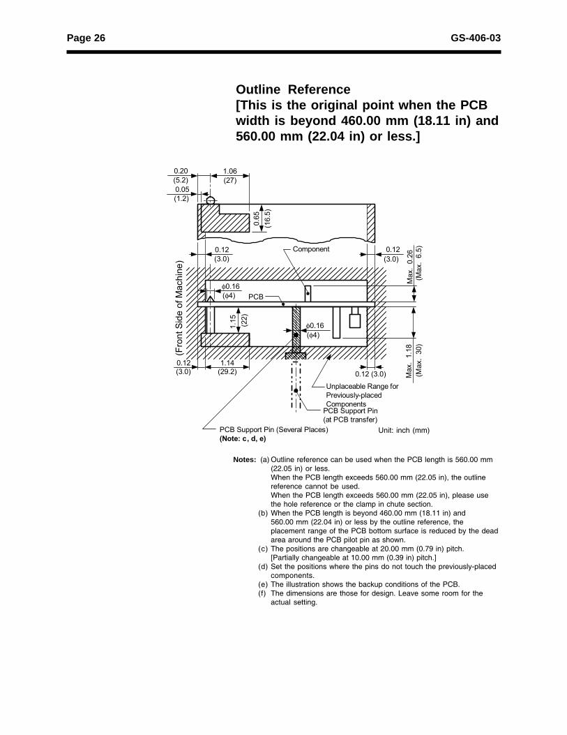
PCB
φ0.16
PCB Support Pin(at PCB transfer)
Unplaceable Range forPreviously-placedComponents
Component(3.0)
Max
. 0.
26
0.12
(Fro
nt S
ide
of M
achi
ne) (3.0)
0.12
(Max
. 6.
5)M
ax.
1.18
(Max
. 30
)
0.12 (3.0)0.12
(φ4)
φ0.16(φ4)
(22)
1.15
(1.2)0.05
(3.0)1.14
(29.2)
(16.
5)0.
65
(5.2)0.20
(27)1.06
PCB Support Pin (Several Places)(Note: c, d, e)
Notes: (a) Outline reference can be used when the PCB length is 560.00 mm(22.05 in) or less.When the PCB length exceeds 560.00 mm (22.05 in), the outlinereference cannot be used.When the PCB length exceeds 560.00 mm (22.05 in), please usethe hole reference or the clamp in chute section.
(b) When the PCB length is beyond 460.00 mm (18.11 in) and560.00 mm (22.04 in) or less by the outline reference, theplacement range of the PCB bottom surface is reduced by the deadarea around the PCB pilot pin as shown.
(c) The positions are changeable at 20.00 mm (0.79 in) pitch.[Partially changeable at 10.00 mm (0.39 in) pitch.]
(d) Set the positions where the pins do not touch the previously-placedcomponents.
(e) The illustration shows the backup conditions of the PCB.(f) The dimensions are those for design. Leave some room for the
actual setting.
Unit: inch (mm)
Outline Reference[This is the original point when the PCBwidth is beyond 460.00 mm (18.11 in) and560.00 mm (22.04 in) or less.]
Page 27GS-406-03
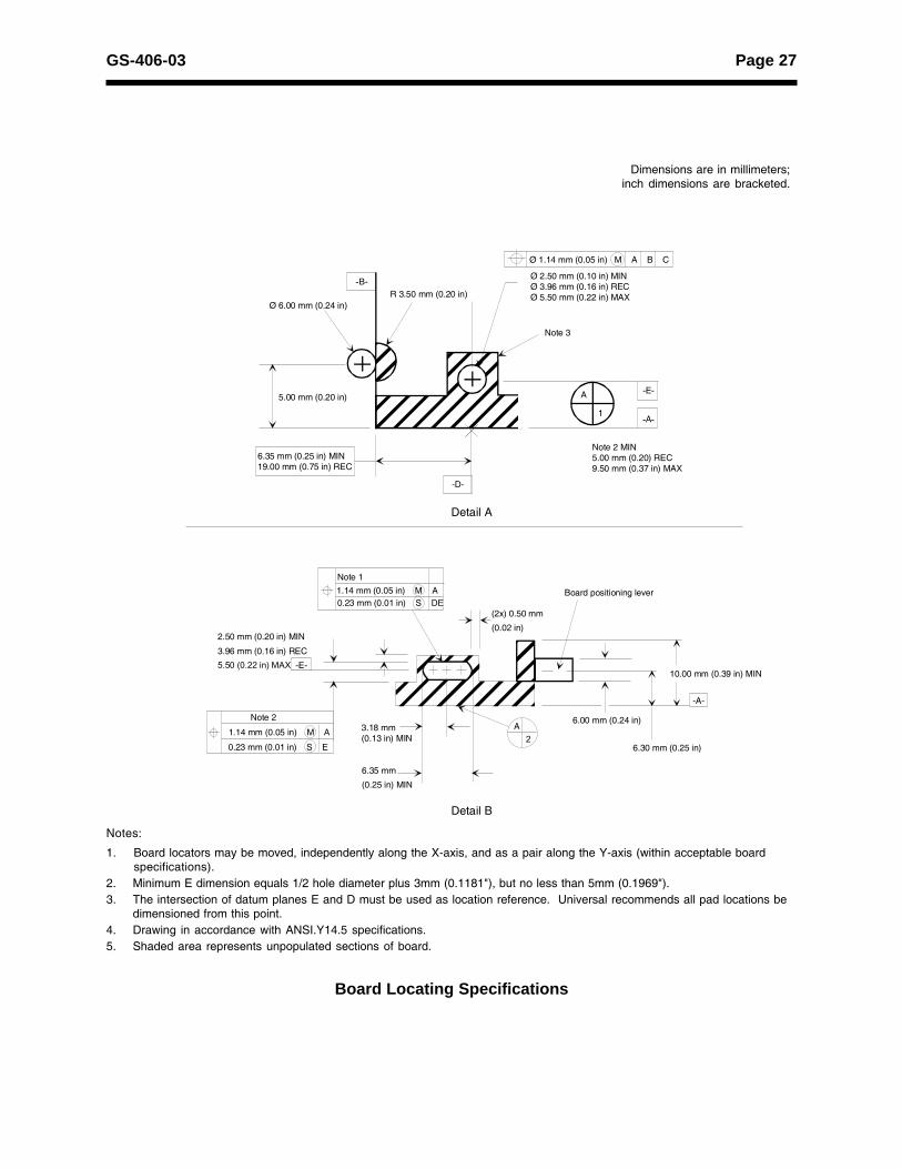
Board Locating Specifications
Dimensions are in millimeters;inch dimensions are bracketed.
Notes:
1. Board locators may be moved, independently along the X-axis, and as a pair along the Y-axis (within acceptable boardspecifications).
2. Minimum E dimension equals 1/2 hole diameter plus 3mm (0.1181"), but no less than 5mm (0.1969").3. The intersection of datum planes E and D must be used as location reference. Universal recommends all pad locations be
dimensioned from this point.4. Drawing in accordance with ANSI.Y14.5 specifications.5. Shaded area represents unpopulated sections of board.
R 3.50 mm (0.20 in)
Ø 1.14 mm (0.05 in) M A B C
Ø 2.50 mm (0.10 in) MINØ 3.96 mm (0.16 in) RECØ 5.50 mm (0.22 in) MAX
Note 3
A
1
6.35 mm (0.25 in) MIN19.00 mm (0.75 in) REC
-D-
Note 2 MIN5.00 mm (0.20) REC9.50 mm (0.37 in) MAX
5.00 mm (0.20 in)
Ø 6.00 mm (0.24 in)
-B-
-E-
-A-
Detail A
1.14 mm (0.05 in) M A0.23 mm (0.01 in) S DE
(2x) 0.50 mm
(0.02 in)
Board positioning lever
6.30 mm (0.25 in)
6.00 mm (0.24 in)A
23.18 mm(0.13 in) MIN
6.35 mm
(0.25 in) MIN
Note 2
1.14 mm (0.05 in) M A
0.23 mm (0.01 in) S E
2.50 mm (0.20 in) MIN
3.96 mm (0.16 in) REC
5.50 (0.22 in) MAX -E-
-A-
Detail B
10.00 mm (0.39 in) MIN
Note 1
Page 28 GS-406-03
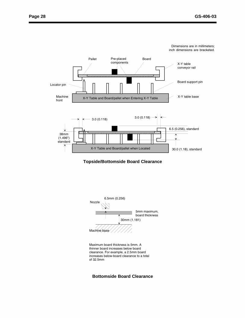
Topside/Bottomside Board Clearance
Bottomside Board Clearance
Dimensions are in millimeters;inch dimensions are bracketed.
Locator pin
Pallet Board
Board support pin
X-Y table baseX-Y Table and Board/pallet when Entering X-Y TableMachinefront
X-Y tableconveyor rail
Pre-placedcomponents
3.0 (0.118) 3.0 (0.118)
6.5 (0.256), standard
30.0 (1.18), standard
38mm(1.496")standard
X-Y Table and Board/pallet when Located
Nozzle
Machine base
6.5mm (0.256)
30mm (1.181)
Maximum board thickness is 5mm. A thinner board increases below board clearance. For example, a 2.5mm board increases below-board clearance to a total of 32.5mm
5mm maximum, board thickness
Page 29GS-406-03
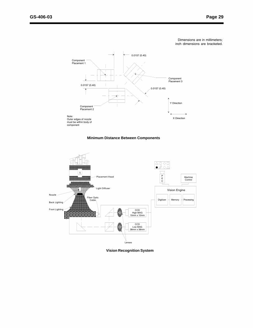
Dimensions are in millimeters;inch dimensions are bracketed.
Minimum Distance Between Components
Vision Recognition System
MachineControl
PEC
Vision Engine
Digitizer Memory Processing
CCDHigh MAG
10mm x 10mm
CCDLow MAG
38mm x 38mm
Lenses
1Placement Head
Light Diffuser
Fiber OpticCable
Nozzle
Back Lighting
Front Lighting
ComponentPlacement 1
0.0157 (0.40)
ComponentPlacement 2
Note:Outer edges of nozzlemust be within body ofcomponent
ComponentPlacement 3
Y Direction
X Direction
0.0157 (0.40)
0.0157 (0.40)

Page 30 GS-406-03
4797A/B Pattern Error Correction
Dimensions are in millimeters;inch dimensions are bracketed.
Component Recognition CameraFields of View High: 10 mm x 10 mm (0.394" x 0.394")
Low: 38 mm x 38 mm (1.496" x 1.496")
Camera Resolution High: 17 micrometer/pixel
Low: 67 micrometer/pixel
Pattern Error Correction CameraField of view 12mm x 12mm (0.47" x 0.47")
Camera Resolution 27 micrometer/pixel (0.001"/pixel)
Window Size 1mm x 1mm (0.0394" x 0.0394")
to 5mm x 5mm (0.197" x 0.197")
Recognition Time Approximately 200 ms/mark
1 (0.0394)
1 (0.0394)
4.5 (0.1772)
(Machine front)
Board Origin
Fiducial mark location
50 to 460 (2 to18)
50 to 381(2 to15)
Fiducial must have at least 1mmclearance on all sides
1 (0.0394)
The non-shaded area is therange where a P.E.C. markcan be set
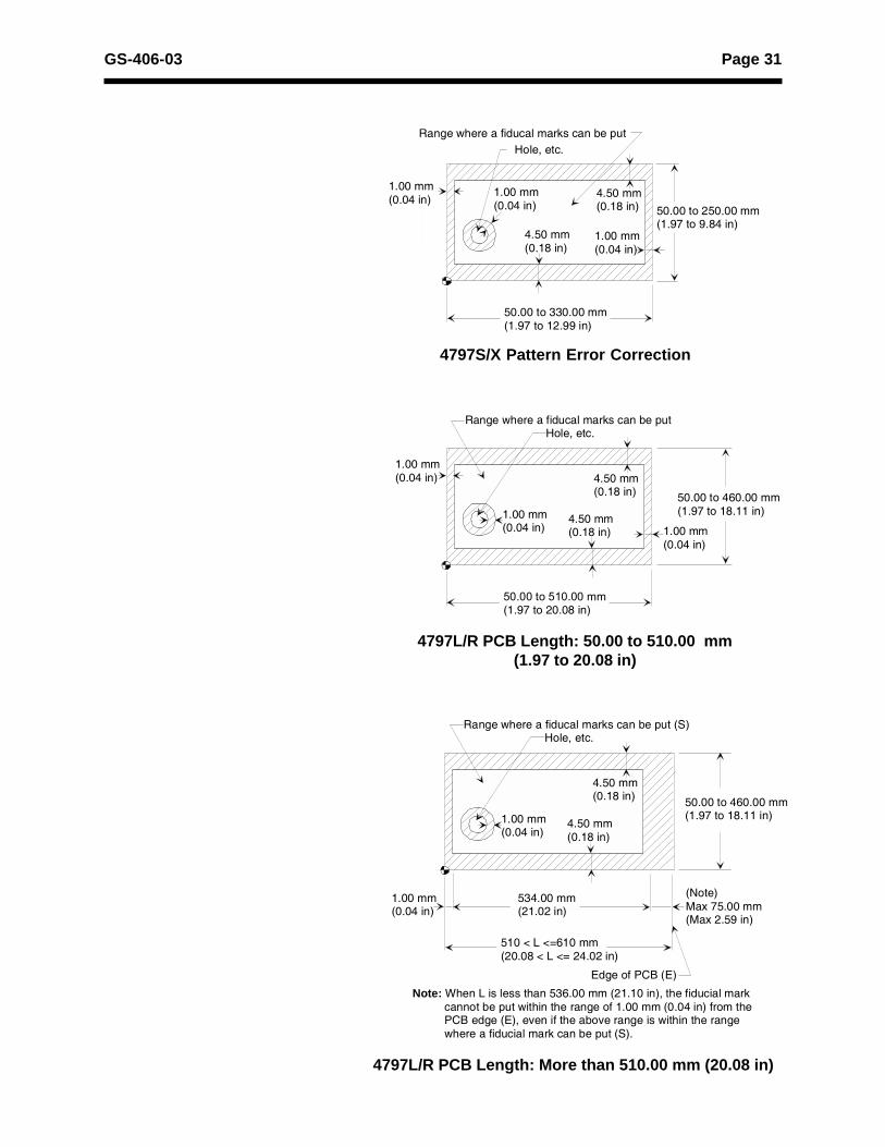
4797B/X/L/R Pattern Error Correction
Page 31GS-406-03
4797L/R PCB Length: 50.00 to 510.00 mm(1.97 to 20.08 in)
50.00 to 510.00 mm(1.97 to 20.08 in)
50.00 to 460.00 mm(1.97 to 18.11 in)
1.00 mm(0.04 in)
4.50 mm(0.18 in)
4.50 mm(0.18 in)
1.00 mm(0.04 in)
1.00 mm(0.04 in)
Hole, etc.Range where a fiducal marks can be put
4797L/R PCB Length: More than 510.00 mm (20.08 in)
50.00 to 330.00 mm(1.97 to 12.99 in)
1.00 mm(0.04 in)
4.50 mm(0.18 in)
4.50 mm(0.18 in)
1.00 mm(0.04 in)
1.00 mm(0.04 in)
Hole, etc.Range where a fiducal marks can be put
50.00 to 250.00 mm(1.97 to 9.84 in)
4797S/X Pattern Error Correction
where a fiducal marks can be put
etc.
4.50 mm(0.18 in)
4.50 mm(0.18 in)
1.00 mm(0.04 in)
Hole, etc.Range where a fiducal marks can be put (S)
1.00 mm(0.04 in)
534.00 mm(21.02 in)
510 < L <=610 mm(20.08 < L <= 24.02 in)
(Note)Max 75.00 mm(Max 2.59 in)
50.00 to 460.00 mm(1.97 to 18.11 in)
Note: When L is less than 536.00 mm (21.10 in), the fiducial mark cannot be put within the range of 1.00 mm (0.04 in) from the PCB edge (E), even if the above range is within the range where a fiducial mark can be put (S).
Edge of PCB (E)

Page 32 GS-406-03
Recommended Computer SpecificationsProcessor Celeron 566 MHz (or faster)
RAM 128 MB (or more)
Hard Drive Capacity 10 GB free space
Graphics Adapter PCI SVGA w/1 MB
Ports LAN port, 2 serial I/O
Operating Software Windows NT Workstation 4.0
Application Software UCT 53 or HSP UPS (OS/2)
FDD/CD-ROM 3.5 in FDD, 10x/24x max CD-ROM
Durable Floor Load SpecificationsModel Factory Floor Loading Reference Document
Specification Required4797S/X 1140 kg/m2 (233 lbs/ft2) SPD-C056-001
4797A/B 1020 kg/m2 (209 lbs/ft2) SPD-C054-001
4797L 847 kg/m2 (173 lbs/ft2) SPD-C064-001
4797R 900kg/m2 (215 lbs/ft2) SPD-C082-001
Page 33GS-406-03
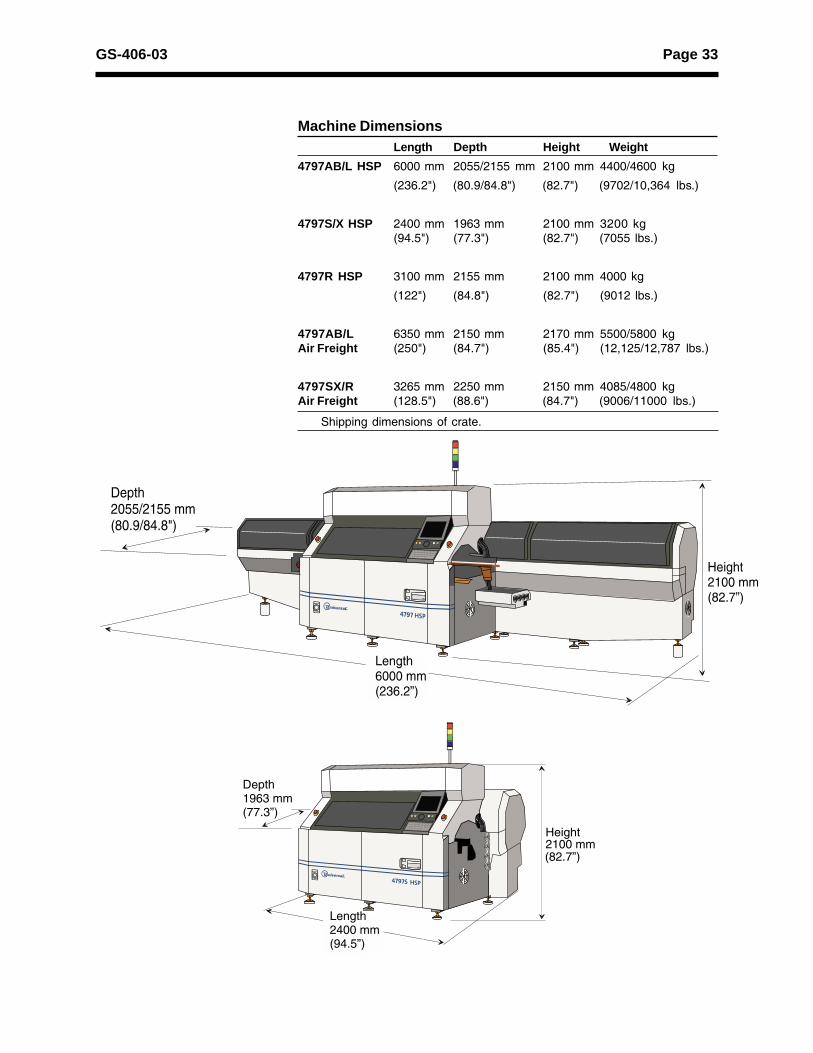
Machine DimensionsLength Depth Height Weight
4797AB/L HSP 6000 mm 2055/2155 mm 2100 mm 4400/4600 kg
(236.2") (80.9/84.8") (82.7") (9702/10,364 lbs.)
4797S/X HSP 2400 mm 1963 mm 2100 mm 3200 kg(94.5") (77.3") (82.7") (7055 lbs.)
4797R HSP 3100 mm 2155 mm 2100 mm 4000 kg
(122") (84.8") (82.7") (9012 lbs.)
4797AB/L 6350 mm 2150 mm 2170 mm 5500/5800 kgAir Freight (250") (84.7") (85.4") (12,125/12,787 lbs.)
4797SX/R 3265 mm 2250 mm 2150 mm 4085/4800 kgAir Freight (128.5") (88.6") (84.7") (9006/11000 lbs.)
Shipping dimensions of crate.
2100 mm(82.7”)
Height
Depth1963 mm(77.3”)
Length2400 mm(94.5”)
Page 34 GS-406-03
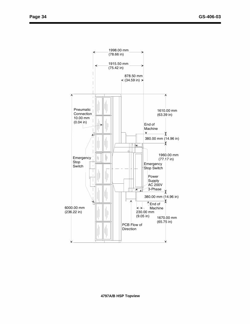
4797A/B HSP Topview
1998.00 mm(78.66 in)
1915.50 mm(75.42 in)
878.50 mm(34.59 in)
1610.00 mm(63.39 in)
End of Machine
380.00 mm (14.96 in)
EmergencyStop Switch
PowerSupply AC 200V3-Phase
380.00 mm (14.96 in)
1670.00 mm(65.75 in)
End ofMachine
230.00 mm(9.05 in)
EmergencyStopSwitch
PneumaticConnection10.00 mm(0.04 in)
1960.00 mm(77.17 in)
PCB Flow ofDirection
6000.00 mm(236.22 in)
Page 35GS-406-03
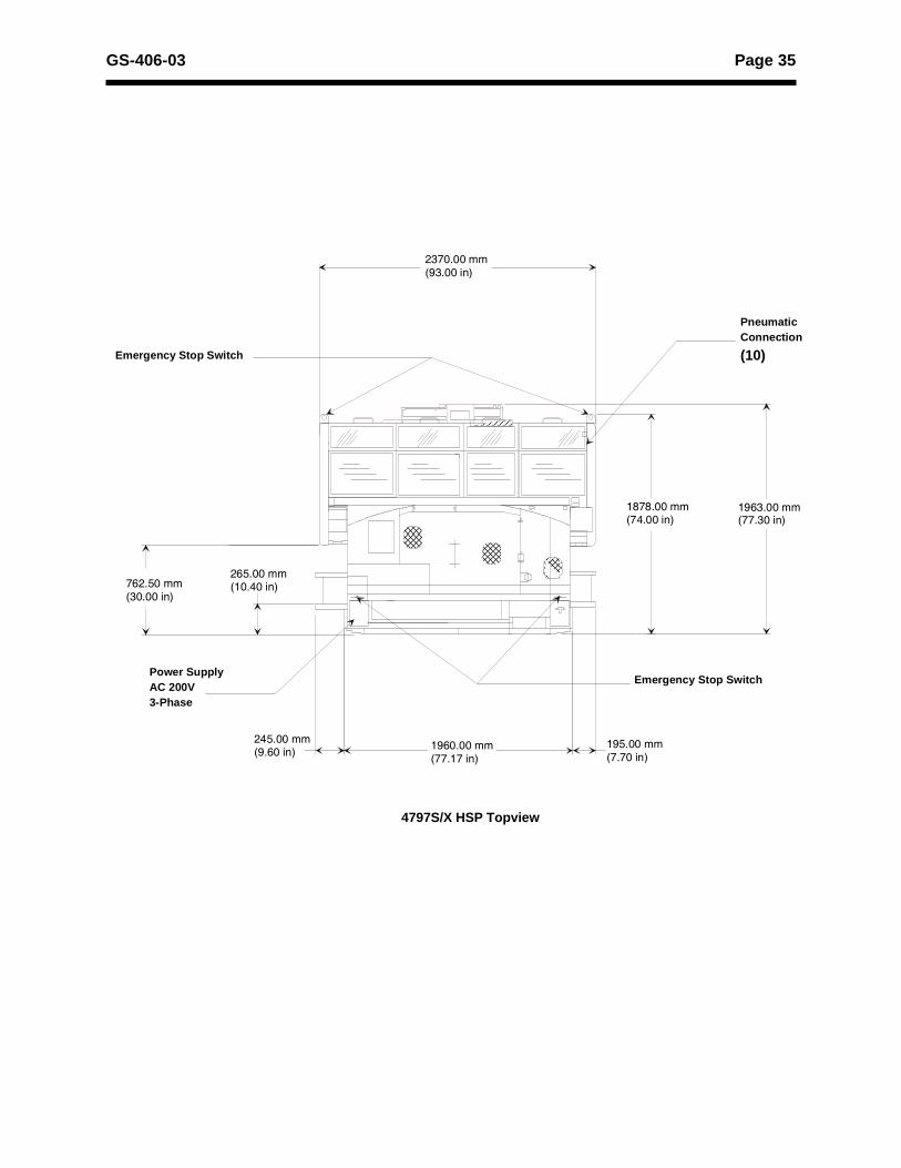
Emergency Stop Switch
PneumaticConnection
(10)
Power SupplyAC 200V3-Phase
1960.00 mm(77.17 in)
195.00 mm(7.70 in)
245.00 mm(9.60 in)
265.00 mm(10.40 in)
1878.00 mm(74.00 in)
1963.00 mm(77.30 in)
Emergency Stop Switch
2370.00 mm(93.00 in)
762.50 mm(30.00 in)
4797S/X HSP Topview
Page 36 GS-406-03
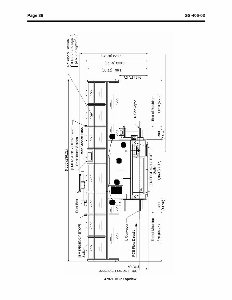
4797L HSP Topview
Page 37GS-406-03
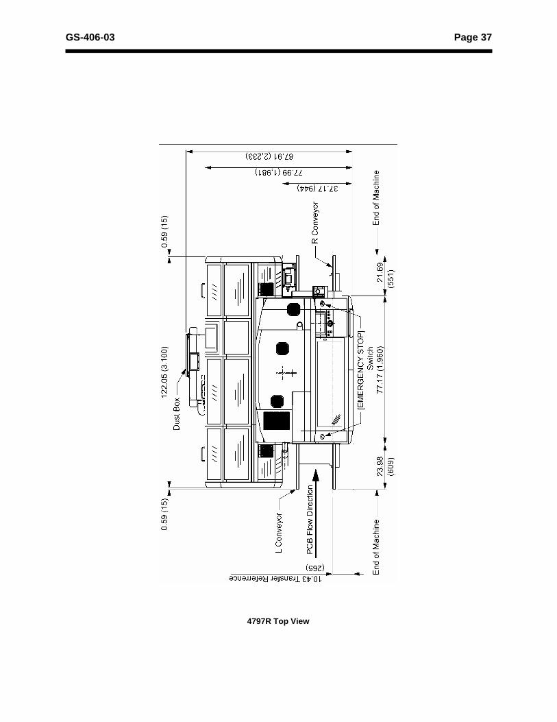
4797R Top View
Page 38 GS-406-03
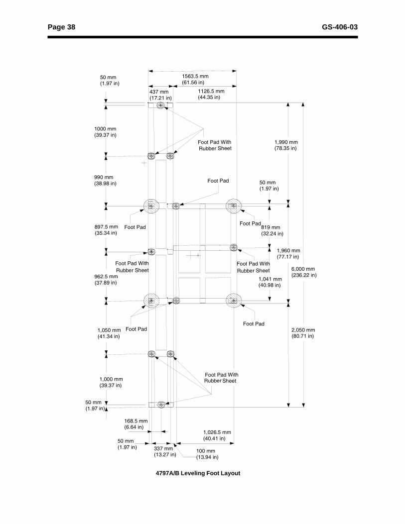
4797A/B Leveling Foot Layout
Foot Pad WithRubber Sheet
Foot Pad
Foot PadFoot Pad
Foot Pad
Foot Pad With Rubber Sheet
Foot Pad
Foot Pad WithRubber Sheet
50 mm(1.97 in)
100 mm(13.94 in)
168.5 mm(6.64 in)
50 mm(1.97 in) 337 mm
(13.27 in)
1,026.5 mm(40.41 in)
437 mm(17.21 in)
1563.5 mm(61.56 in)
1126.5 mm(44.35 in)
50 mm(1.97 in)
50 mm(1.97 in)
1000 mm(39.37 in)
990 mm(38.98 in)
1,990 mm(78.35 in)
897.5 mm(35.34 in)
962.5 mm(37.89 in)
1,041 mm(40.98 in)
819 mm(32.24 in)
1,960 mm(77.17 in)
6,000 mm(236.22 in)
1,050 mm(41.34 in)
1,000 mm(39.37 in)
Foot Pad WithRubber Sheet
2,050 mm(80.71 in)
Page 39GS-406-03
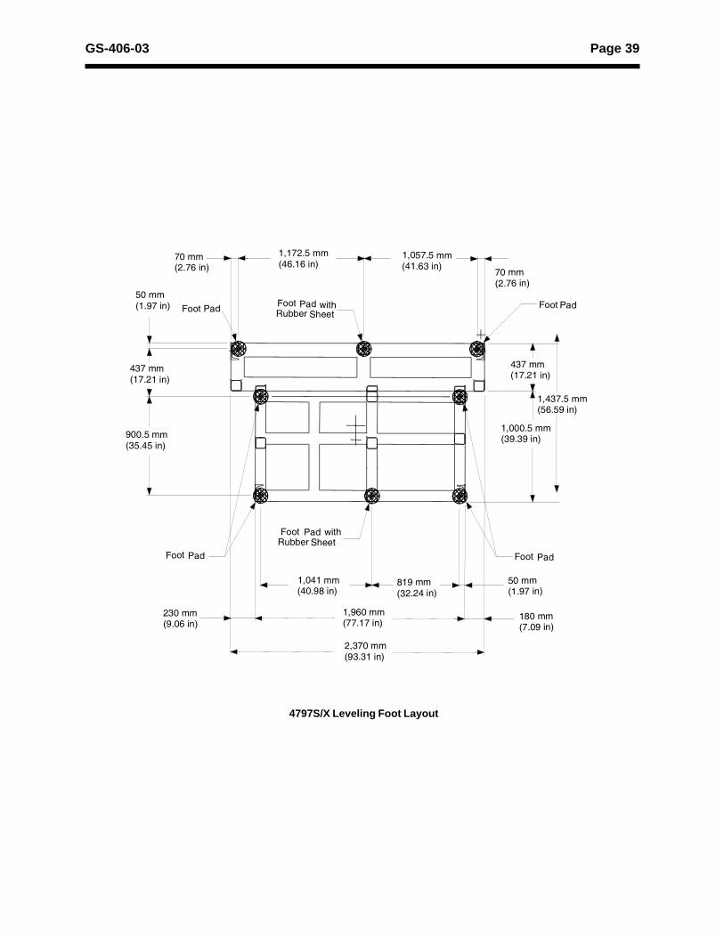
4797S/X Leveling Foot Layout
70 mm(2.76 in)
50 mm(1.97 in)
180 mm(7.09 in)
Foot Pad Foot Pad withRubber Sheet
Foot Pad
Foot Pad
Foot Pad withRubber Sheet
Foot Pad
50 mm(1.97 in)
230 mm(9.06 in)
70 mm(2.76 in)
437 mm(17.21 in)
900.5 mm(35.45 in)
1,172.5 mm(46.16 in)
1,057.5 mm(41.63 in)
437 mm(17.21 in)
1,000.5 mm(39.39 in)
1,437.5 mm(56.59 in)
1,041 mm(40.98 in)
819 mm(32.24 in)
1,960 mm(77.17 in)
2,370 mm(93.31 in)
Page 40 GS-406-03
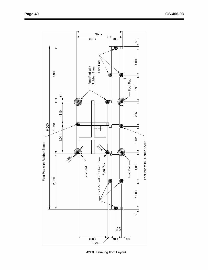
4797L Leveling Foot Layout

Page 41GS-406-03
2.3 Foot Pad (Base Frame)
4797S Leveling Foot Layout
Page 42 GS-406-03
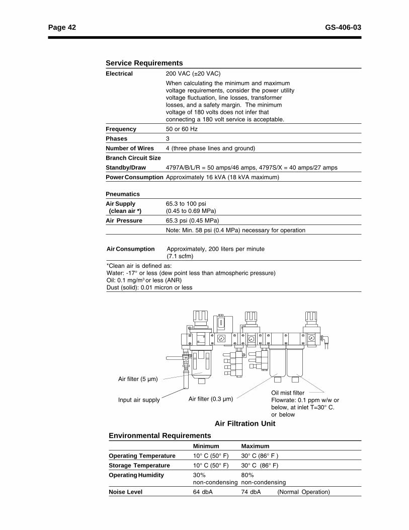
Air Filtration Unit
Air filter (5 µm)
Air filter (0.3 µm)Oil mist filterFlowrate: 0.1 ppm w/w orbelow, at inlet T=30° C.or below
Input air supply
Service RequirementsElectrical 200 VAC (±20 VAC)
When calculating the minimum and maximumvoltage requirements, consider the power utilityvoltage fluctuation, line losses, transformerlosses, and a safety margin. The minimumvoltage of 180 volts does not infer thatconnecting a 180 volt service is acceptable.
Frequency 50 or 60 Hz
Phases 3
Number of Wires 4 (three phase lines and ground)
Branch Circuit SizeStandby/Draw 4797A/B/L/R = 50 amps/46 amps, 4797S/X = 40 amps/27 amps
Power Consumption Approximately 16 kVA (18 kVA maximum)
PneumaticsAir Supply 65.3 to 100 psi (clean air *) (0.45 to 0.69 MPa)
Air Pressure 65.3 psi (0.45 MPa)
Note: Min. 58 psi (0.4 MPa) necessary for operation
Air Consumption Approximately, 200 liters per minute(7.1 scfm)
*Clean air is defined as:Water: -17° or less (dew point less than atmospheric pressure)Oil: 0.1 mg/m3 or less (ANR)Dust (solid): 0.01 micron or less
Environmental RequirementsMinimum Maximum
Operating Temperature 10° C (50° F) 30° C (86° F )
Storage Temperature 10° C (50° F) 30° C (86° F)
Operating Humidity 30% 80%non-condensing non-condensing
Noise Level 64 dbA 74 dbA (Normal Operation)