general specifications direct in situ zirconia oxygen...
TRANSCRIPT

GeneralSpecifications
Model ZR22G, ZR402G, and ZR202GDirect In Situ Zirconia Oxygen Analyzers
Yokogawa Corporation of America2 Dart Road Newnan, Georgia U.S.A. 30265Tel: 1-800-258-2552 Fax: 1-770-254-0928
GS O11M12A01-01E-A©Copyright January 2001
1st Edition 9/02(rev. 4th Ed)
Features
• The built-in heater assembly of the probe can be replacedon site, reducing maintenance costs.
• The probe uses a long-life, high reliability Zirconia sensor• The probe uses three-reference air supply methods
(natural air convection, instrument air, and pressurecompensated) in its applications.
• The separate type converter incorporates an LCD touch-screen for ease of operation.
• This converter is used as an oxygen analyzer.• The integrated type integrates both probe and converter, to
reduce wiring, piping, and installation costs. This type ofunit uses an optical switch for ease of operation at the site.
• Remote maintenance using digital communications(HART®) reduces maintenance costs.
Overview
The ZR22 is a direct insertion (in-situ) type oxygendetector. This detector when inserted through the wall ofa flue or furnace allows continuous monitoring of theoxygen concentration of combustion gas via a zirconiacell. Yokogawa offers three (3) types of oxygen detectors:low temperature, high temperature, and pressurecompensated. These detectors are subject to harshenvironments because they are directly mounted incombustion applications. We recommend utilizing one ofthe many accessories Yokogawa has available toincrease the life of the detector.
ZR402G
+
–
4 to 20 mA DC signal line withsuperimposed HART AC signal
Control room
Terminal board
Receiving instrumentload resistance: 250 to 550
Relayingterminals
HARTCommunicator
Model 275
HARTCommunicator
Model 275
HARTCommunicator
Model 275
Ao+
Ao-
Ao1+
Ao1-
EXA ZR402G
F34.EPS
ZR202G

Basic System Configuration
System configuration - Separate type
System configuration - Integrated type
2
GS O11M12A01-01E-A
Instrument air
Calibration gas pressure regulator
Air Set
Needle valveflowmeter
Reference gas
Calibration gas
Check valve ~
Zero gas cylinder
Model AC1 Auto Calibration unit
Model ZR22G Separate type Zirconia Oxygen/ High Temperature Humidity Analyzer, Detector
Model ZR402G Converter
Calibration gasunit case
F03.EPS
EXA ZR402G
*1
*2
100 to 240 V ACContact inputAnalog output, contact outputDigital output (HART)
Signal (6-core shield cable)
Heater (2-core)
System configuration Example 1 of Separate type Analyzer
Automatic calibration system uses instrument air for reference gas.For the calibration gas, a standard gas cylinder may be used for more accurate calibration.
Applications: Oxygen concentration monitoring and control in large boilers (for private power generation and for business use) and in heating furnaces, and the like. Humidity monitoring and control in drying furnaces and humidifiers.
*3
~ 100 to 240 V ACAuto Calibration unit
Reference gas
Calibration gas (Zero)
Contact inputAnalog output, contact outputDigital output (HART)
Air Set
Instrument air
Calibration gasunit case
Calibration gas pressure regulator
Zero gas cylinder
Model ZR202G Integrated type Zirconia Oxygen/ High Temperature Humidity Analyzerwith auto calibration (ZR202G-hhh-h-h-A-h-h-h-h-A)
F05.EPS
Span gas
*3
System configuration Example 1 of Integrated type Analyzer
For an integrated type as shown in the figure above.Applications: Oxygen concentraion monitoring and control in large boilers
(for private power generation and for business use) and in heating furnaces, and the like. Humidity monitoring and control in drying furnaces and humidifiers
Note: The installation temperature limits range for integrated type analyzer is -20 to 55 8C.
*2
*1 Shield cable:Use shielded signal cables, and connect the shields to the FG terminal of the converter.
*2 Select the desired probe from the Probe Configuration table on page 4.*3 When a zirconia oxygen analyzer is used, 100% N2 gas cannot be used as the zero gas. Use approx.
1 vol% O2 gas (N2-balanced).

System Components
Detector Components STANDARD SPECIFICATIONS
(Oxygen Analyzer)
General Specifications
3
GS O11M12A01-01E-A
1
2
3
4
5
6
7
8
9
10
11
12
System Components
Model ZR22G Separate type Zirconia Oxygen Analyzers/ High Temperature Humidity Analyzers,Detector
Model ZR402G Separate type Zirconia Oxygen / High Temperature Humidity Analyzer, Converter(*1)
Model ZR202G Integrated type Zirconia Oxygen Analyzers/ High Temperature Humidity Analyzers
Model ZR22P Adapter for High Temperature Probe of separate type Zirconia Oxygen Analyzer
M1132KA Auxiliary Ejector for High Temperature Probe of separate type Oxygen Analyzer
Model ZR22R Probe Protector for Zirconia Oxygen Analyzers
Separate type Integrated type
Ex.1 Ex.2 Ex.3 Ex.1 Ex.2 Ex.3System config. System config.
ZA8F-D
Model AC1-D Automatic Calibration Unit for Separate type Analyzer
Automatic Calibration Unit for Integrated type Analyzer (*2)
M1132KN Check Valve for Calibration-gas line
M1132ZX Pressure Regulator for Gas Cylinder
ZR22A, ZR202A Heater Assembly for Spare Parts
( )( )
Detector(ZR22G or ZR202G)
F06.EPS
Dust filter forOxygen Analyzer
(E7042UQ)) +
Probe Protector(ZR22R)Gas Flow
Detector(ZR22G or ZR202G)
Detector(ZR22G or ZR202G)
Process gas temperature 0 to 700C Process gas temperature 0 to 1800C
Mounting Insertionlength General-use Probe High temperature detectorApplication Application
Horizontalto
vertical
Horizontalto
vertical
Horizontalto
vertical
Vertical
Vertical
0.4to
2 m
0.4to
2 m
2.5 mor more
3 m or less
2.5 m or more
Boiler
Heating furnace
For pulverizedcoal boilerwith gas flowvelocity10 m/s or more
Black liquidrecovery boiler
CementKiln
Sampleoutlet
Sample inlet
Hightemperaturedetector
Heatingfurnace
High temperature auxiliaryejector (M1132KE)
Pressure gauge
Needlevalve
Blow
Absorptionstructure
Inlet
Ejectorassy.
Transport Tubefor hightemperature useZR22P
Sample inlet
Application ExampleSeparate and integrated type Zirconia Oxygen Analyzers
• Large, medium and small boilers (boilers for power generation: heavy oil, gas or coal)• Various industrial furnaces (refinery process/iron manufacture heating furnace, coal kiln, and black liquid recovery boilers)
For other applications, contact Yokogawa Electric Corporation.• May not be applicable corrosive gas such as ammonia is present-check with YOKOGAWA.

Oxygen Analyzer
Measurement: Oxygen concentration in combustionexhaust gas and mixed gas (excludingflammable gases).
Measurement System: Zirconia system Oxygen Concentration: 0.01 to 100 vol% O2Output Signal: 4 to 20 mA DC (maximum load
resistance 550Ω)Measurement Range: Any setting in the range of 0 to 5
through 0 to 100 vol% O2Digital Communication (HART®): 250 to 550Ω,
depending on number of field devicesconnected to the loop (multi-drop mode).
Display Range: 0 to 100 vol% O2Warm-up Time: Approx. 20 min.Repeatability: ±0.5% Maximum value of set range.Linearity: (Excluding standard gas tolerance)±1% Maximum value of set range.Drift: Both zero and span ±2% Maximum value of set
range/monthResponse Time: Response of 90% within 5
seconds. (Measured after gas is introducedfrom calibration-gas inlet and analog outputstarts changing.)
Accuracy: [(Repeatability)2] + (Linearity)2 + (CalibrationGas Accuracy)2] 1/2
1. ZR22G Separate type Zirconia OxygenAnalyzer, Detector
Oxygen Analyzer
Sample Gas Temperature: -0.725 to 700°C (Probe only)700 to 1400°C (with High Temperature ProbeAdapter)
Sample Gas Pressure: -0.725 to +0.73 psi(-0.725 to +36.3 requires pressurecompensation.)
Probe Length: 0.15, 0.4, 0.7, 1.0, 1.5, 2.0, 2.5, 3.0, 3.6,4.2, 4.8, 5.4m
Probe Material: SUS 316 (JIS)Ambient Temperature: -20 to +150°C (-4 to 302°F)Reference Air System: Natural Convection, Instrument
Air, or pressure compensatedInstrument Air System: Pressure; 29psi + the pressure
inside the furnace (It is recommended to useclean, dry plant air.)Consumption; Approx. 1Nl/min
Wetted Material: SUS 316 (JIS), Zirconia, SUS 304(JIS) (flange), Hastelloy B, (Inconel 600, 601),
Construction: Heater and thermocouple replaceableconstruction. Non explosion-proof.Equivalent to NEMA4X/IP 66 (recirculation tofurnace with pressure compensated only)
Terminal Box Case: Material; Aluminum alloy
Terminal Box Paint Color: Case; Off-white (Munsell0.6GY3.1/2.0)Cover; Moss green (Munsell 2.5Y8.4/1.2)
Finish: Polyurethane corrosion-resistance coating
Gas Connection: 1/4 FNPTWiring Connection: 1/2 NPTInstallation: Flange mounting
Weight:Insertion length of 0.4 m: approx. 6 kg (JIS 5K-65) /
approx. 11 kg (ANSI 150-4)Insertion length of 1.0 m: approx. 8 kg (JIS 5K-65) /
approx. 13 kg (ANSI 150-4)Insertion length of 1.5 m: approx. 10 kg (JIS 5K-65) /
approx. 15 kg (ANSI 150-4)Insertion length of 2.0 m: approx. 12 kg (JIS 5K-65) /
approx. 17 kg (ANSI 150-4)Insertion length of 3.0 m: approx. 15 kg (JIS 5K-65) /
approx. 20 kg (ANSI 150-4)Insertion length of 3.6 m: approx. 17 kg (JIS 5K-65) /
approx. 22 kg (ANSI 150-4)Insertion length of 4.2 m: approx. 19 kg (JIS 5K-65) /
approx. 24 kg (ANSI 150-4)Insertion length of 4.8 m: approx. 21 kg (JIS 5K-65) /
approx. 26 kg (ANSI 150-4)Insertion length of 5.4 m: approx. 23 kg (JIS 5K-65) /
approx. 28 kg (ANSI 150-4)
2. ZR402G Separate type Zirconia OxygenAnalyzer, Converter
Operated using an LCD touchscreen on the converter.Display: LCD display of size 320 by 240 dot with
touchscreen.Output Signal: 4 to 20 mA DC, two points (maximum
load resistance 550 V)Contact Output Signal: four points (one is fail-safe,
normally open)Contact Input: two pointsAuto-calibration Output: Two points (for dedicated auto-
calibration unit)Ambient Temperature: -20 to +558CStorage Temperature: -30 to +708CAmbient Humidity : 0 to 95 %RH (non-condensing)Installation Altitude: 2000 m or lessCategory based on IEC 1010: II (Note)Pollution degree based on IEC 1010: 2 (Note)
Note: Installation category, called over-voltagecategory, specifies impulse withstand voltage.Category II is for electrical equipment.Pollution degree indicates the degree ofexistence of solid, liquid, gas or otherinclusions which may reduce dielectricstrength. Degree 2 is the normal indoorenvironment.
Power Supply Voltage: Ratings; 100 to 240 V ACAcceptable range; 85 to 264 V AC
Power Supply Frequency: Ratings; 50/60 HzAcceptable range; 45 to 66 HzPower Consumption: Max. 300 W, approx. 100 W for
ordinary use.
Safety and EMC conforming standardsSafety: Conforms to EN 61010-1: 1993
CSA C22.2 No.1010-1 certifiedUL 3111-1 certified
4
GS O11M12A01-01E-A

EMC: Conforms to EN 61326: 1998Maximum Distance between Probe and Converter:
Conductor two-way resistance must be 10V orless (when a 1.25 mm2 cable or equivalent isused, 300 m or less.)
Construction: Outdoor installation, NEMA4 or equivalent(with conduit holes completely sealed with aplastic cable gland optional)
Wiring Connection: G1/2, Pg13.5, M20 by 1.5mm, 1/2NPT, eight holes
Installation: Panel, wall or pipe mountingCase: Aluminum alloyPaint Color: Door; Moss green (Munsell 0.6GY3.1/2.0)
Case; Off-white (Munsell 2.5Y8.4/1.2)Finish: Polyurethane corrosion-resistance coatingWeight: Approx. 6 kg
FunctionsDisplay Functions:
Value Display; Displays values of the measured oxygenconcentration
Graph Display; Displays trends of measured oxygenconcentration
Data Display; Displays various useful data formaintenance, such as cell temperature,reference junction temperature,maximum/minimum oxygen concentration, orthe like.
Status Message; Indicates an alarm or error occurrencewith flashing of the corresponding icon.Indicates status such as warming-up,calibrating, or the like by icons.
Alarm, Error Display: Displays alarms such as“Abnormal oxygen concentration” or errorssuch as “Abnormal cell e.m.f.” when any suchstatus occurs.
Calibration Functions:Auto-Calibration; Requires the Auto-calibration Unit. It
calibrates automatically at specified intervals.Semi-auto Calibration; Requires the Auto-calibration
Unit. Input calibration direction on thetouchscreen or contact, then it calibratesautomatically afterwards.
Manual Calibration; Calibration with opening/closing thevalve of calibration gas in operationinteractively with an LCD touchscreen.
Blowback Function:Output through the contact in the set periodand time. Auto/semi-auto selectable.
Maintenance Functions:Can operate updated data settings in dailyoperation and checking. Display data settings,calibration data settings, blowback datasettings, current output loop check,input/output contact check.
Setup Functions:Equipment settings, current output datasettings, alarm data settings, contact datasettings, other settings.
Self-diagnosis:This function diagnoses conditions of theconverter or the probe and indicates whenany abnormal condition occurs.
Password Functions:Enter your password to operate the analyzerexcepting data display. Individual passwordscan be set for maintenance and setup.
Display and Setting Content:Measuring Related items: Oxygen concentration
(vol% O2), output current value (mA), airration, moisture quantity (in hot gases)(vol% H2O)
Display Items: Cell temperature (°C), thermocouplereference junction temperature (°C),maximum/minimum/average oxygenconcentration (vol% O2), cell e.m.f. (mV), cellresistance (Ω), cell condition (in four grades),heater on-time rate (%), calibration record (tentimes), time (year/month/day/hour/minute)
Calibration Setting Items: Span gas concentration(vol% O2), zero gas concentration (vol% O2),calibration mode (auto, semi-auto, manual),calibration type and method (zero-spancalibration, zero calibration only, spancalibration only), stabilization time (min.sec),calibration time (min.sec), calibration period(day/hour), starting time(year/month/day/hour/minute)
Equipment Related Items: Measuring gas selectionOutput Related Items: Analog output/output mode
selection, output conditions when warming-up/maintenance/calibrating (duringblowback)/abnormal, 4 mA/20 mA pointoxygen concentration (vol% O2), timeconstant, preset values when warming-up/maintenance/calibrating (during blowback)/abnormal, output preset values on abnormal
Alarm Related Items: Oxygen concentration high-alarm/high-high alarm limit values (vol% O2),oxygen concentration low-alarm/low-low alarmlimit values (vol% O2), oxygen concentrationalarm hysteresis (vol% O2), oxygenconcentration alarm detection, alarm delay(seconds)
Contact Related Items: Selection of contact input 1 and 2,selection of contact output 1 to 4 (abnormal,high-high alarm, high-alarm, low-alarm, low-low alarm, maintenance, calibrating, rangeswitching, warming-up, calibration-gaspressure decrease, temperature high-alarm,blowback, flameout gas detection)
Converter Output: Two points mA analog output (4 to 20mA DC) (maximum load resistance of 550 Ω)and one mA digital output point (HART®)(minimum load resistance of 250 Ω)
.
5
GS O11M12A01-01E-A

Range: any setting between 0 to 5 through 0to 100 vol% O2 in 1 vol% O2, or partial rangeis available (Maximum range value/minimumrange value 1.3 or more)For the log output, the minimum range valueis fixed at 0.1 vol% O2.4 to 20 mA DC linear or log can be selected.
Input/output isolationOutput damping: 0 to 255 seconds.Hold/non-hold selection, preset value settingpossible with hold.
Contact Output: Four points, contact capacity 30 V DC 3 A,250 V AC 3 A (resistive load).Three of the output points can be selected toeither normally energized or normally de-energized status.Delayed functions (0 to 255 seconds) andhysteresis function (0 to 9.9 vol%O2 can beadded to high/low-alarms.The following functions are programmable forcontact outputs.(1) Abnormal, (2) High-high alarm, (3) High-alarm, (4) Low-low alarm, (5) Low-alarm, (6)Maintenance, (7) Calibration, (8) Rangeswitching answer-back, (9) Warm-up, (10) Calibration-gas pressure decrease (answerback of contact input), (11) Temperature high-alarm, (12) Blowbackstart, (13) Flameout gas detection (answerback of contact input)
Contact Input: Two points, voltage-free contactsThe following functions are programmable forcontact inputs:(1) Calibration-gas pressure decrease alarm,(2) Range switching - fixed range if use rangeswitching (3) External calibration start, (4)Process alarm (if this signal is received, theheater power turns off), (5) Blowback start
Contact capacity: Off-state leakage current: 3 mA or lessSelf-diagnosis: Abnormal cell, abnormal cell temperature
(low/high), abnormal calibration, defective A/Dconverter, defective digital circuit
Calibration: Method; zero/span calibrationCalibration mode; automatic, semi-automaticand manual (All are operated interactively withan LCD touchscreen). Either zero or span canbe skipped.Zero calibration-gas concentration settingrange: 0.3 to 100 vol% O2 (0.01 vol% O2 insmallest units).Span calibration-gas concentration settingrange: 4.5 to 100 vol% O2 (0.01 vol%vol% O2in smallest units).Use nitrogen-balanced mixed gas containing10 vol% O2 scale of oxygen and 80 to 100vol% O2 scale of oxygen for standard zero-gas, and standard span-gas respectively.Calibration period; date/time setting: maximum255 days
3. ZR202G Integrated type Zirconia OxygenAnalyzer
Oxygen AnalyzerDisplay: 6-digit LCDSwitch: Three optical switchesOutput Signal: 4 to 20 mA DC, one point (maximum
load resistance 550Ω)Digital Communication (HART®): 250 to 550Ω,
depending on quantity of field devicesconnected to the loop (multi-drop mode).
Contact Output Signal: Two points (one is fail-safe,normally open)
Contact Input Signal: Two pointsSample Gas Temperature: 0 to 700°C
High temperature service– greater than 700°Cis not available.
Sample Gas Pressure: -0.725 to 0.73 psi (-0.725 to +36.3 requires pressurecompensation.)
Probe Length: 0.4, 0.7, 1.0, 1.5, 2.0, 2.5, 3.0mProbe Material: SUS 316 (JIS)Ambient Temperature: -20 to +55°C (-5 to +70°C on the
case surface)Storage Temperature: -30 to +70°CAmbient Humidity: 0 to 95% RH (non-condensing)Installation Altitude: 2000 m or lessCategory based on IEC 1010: II (Note)Pollution degree based on IEC 1010: 2 (Note)Power Supply Voltage: Ratings; 100 to 240 V AC
Acceptable range; 85 to 264 V ACPower Supply Frequency: Ratings; 50/60 Hz
Acceptable range; 45 to 66 HzPower Consumption: Max. 300 W, approx. 100 W for
ordinary use.Safety and EMC conforming standards
Safety: Conforms to EN 61010-1: 1993CSA C22.2 No.1010-1 certifiedUL 3111-1 certifiedEMC: Conforms to EN 61326: 1998Reference Air System: Instrument air, or pressure
compensated Instrument Air System (excluding Natural Convection):
Pressure; 29 psi + the pressure inside thefurnace. (It is recommended to use clean, dryplant air.)Consumption; Approx. 1NI/min
Material in Contact with Gas: SUS 316 (JIS), Zirconia,SUS 304 (JIS) (flange), Hastelloy B, (Inconel600, 601)
Construction: Heater and thermocouple replaceableconstruction. Non explosion-proof.Equivalent to NEMA 4X/IP66 (recirculation tofurnace with pressure compensations only)
Gas Connection: 1/4 FNPTWiring Connection: 1/2 NPT select one type (4 pieces)Installation: Flange mountingCase: Aluminum alloyPaint Color: Cover; Moss green (Munsell 0.6GY3.1/2.0)Case: Off-white (Munsell 2.5Y8.4/1.2)Finish: Polyurethane corrosion-resistance coating
6
GS O11M12A01-01E-A

Weight:Insertion length of 0.4 m: approx. 8 kg (JIS 5K-65) /
approx. 13 kg (ANSI 150-4)Insertion length of 1.0 m: approx. 10 kg (JIS 5K-65) /
approx. 15 kg (ANSI 150-4)Insertion length of 1.5 m: approx. 12 kg (JIS 5K-65) /
approx. 17 kg (ANSI 150-4)Insertion length of 2.0 m: approx. 14 kg (JIS 5K-65) /
approx. 19 kg (ANSI 150-4)Insertion length of 3.0 m: approx. 17 kg (JIS 5K-65) /
approx. 22 kg (ANSI 150-4)
FunctionsDisplay Function: Displays values of the measured
oxygen concentration, etc.Alarm, Error Display: Displays alarms such as “AL-06”
or errors such as “Err-01” when any suchstatus occurs.
Calibration Functions:Auto-calibration; Requires the auto-calibration Unit.
It calibrates automatically at specifiedintervals.
Semi-auto Calibration; Requires the auto-calibrationunit. Input calibration starts signal by opticalswitch or contact, then it calibratesautomatically afterwards.
Manual Calibration; Calibration with opening/closing thevalve of calibration gas in operationinteractively with the optical switch.
Maintenance Functions:Can operate updated data settings in dailyoperation and checking. Display data settings,calibration data settings, test settings (currentoutput loop check, input/output contactcheck).
Setup Functions:Initial settings suit for the plant conditionswhen installing the converter. Current outputdata settings, alarm data settings, contactdata settings, other settings.
Display and setting content:Display Related Items: Oxygen concentration (vol%
O2), Output current value (mA), air ratio,moisture quantity (in hot gases) (vol% H2O),Cell temperature (°C), thermocouple referencejunction temperature (°C),maximum/minimum/average oxygenconcentration (vol% O2), cell e.m.f. (mV), cellinternal resistance (Ω), cell condition (in fourgrades), heater on-time rate (%), calibrationrecord (ten times), time(year/month/day/hour/minute)
Calibration Setting Items: Span gas concentration (vol% O2), zero-gas concentration (vol% O2),calibration mode (auto, semi-auto, manual),calibration type and method (zero-spancalibration, zero calibration only, spancalibration only), stabilization time (min.sec),calibration time (min.sec), calibration period(day/hour), starting time(year/month/day/hour/minute)
Output Related Items: Analog output/output modeselection, output conditions when warming-up/maintenance/calibrating/abnormal, 4 mA/ 20 mA point oxygen concentration(vol% O2), time constant, preset values whenwarming-up/maintenance/calibrating/abnormal,output preset values on abnormal
Alarm Related Items: Oxygen concentration high-alarm/high-high alarm limit values (vol% O2),Oxygen concentration low-alarm/low-lowalarm limit values (vol% O2), oxygenconcentration alarm hysteresis (vol% O2),oxygen concentration alarm detection, alarmdelay (seconds)
Contact Related Items: Selection of contact input 1 and2, selection of contact output 1 and 2(abnormal, high-high alarm, high-alarm, low-alarm, low-low alarm, maintenance,calibrating, range switching, warming-up,calibration-gas pressure decrease, flameoutgas detection (answer back of contact input)
Converter Output: One mA analog output point (4 to 20mA DC (maximum load resistance of 550 Ω)with mA digital output point (HART®)(minimum load resistance of 250 Ω).Range: any setting between 0 to 5 through 0to 100 vol% O2, and partial range is available(Maximum range value/minimum range value1.3 or more) For the log output, the minimum range valuesare fixed at 0.1 vol% O2.4 to 20 mA DC linear or log can be selected.Input/output isolationOutput damping: 0 to 255 seconds.Hold/non-hold selection, preset value settingpossible with hold.
Contact Output: Two points, contact capacity 30 V DC 3 A, 250 V AC 3 A (resistive load)One of the output points can be selected toeither normally energized or normally de-energized status.Delayed functions (0 to 255 seconds) andhysteresis function (0 to 9.9 vol% O2) can beadded to high/low-alarms.The following functions are programmable forcontact outputs.(1) Abnormal, (2) High-high alarm, (3) High-alarm, (4) Low-low alarm, (5) Low-alarm, (6)Maintenance, (7) Calibration, (8) Rangeswitching answer-back, (9) Warm-up, (10)Calibration-gas pressure decrease (answerback of contact input), (11) Flameout gasdetection (answer back of contact input).
Contact Input: Two points, voltage-free contactsThe following functions are programmable forcontact inputs:(1) Calibration-gas pressure decrease alarm,(2) Range switching - fixed ranges if userange switching, (3) External calibration start,(4) Process alarm (if this signal is received,the heater power turns off)
7
GS O11M12A01-01E-A

Self-diagnosis: Abnormal cell, abnormal celltemperature (low/high), abnormalcalibration, A/D converter abnormal, digitalcircuit abnormal
Calibration: Method; zero/span calibrationCalibration mode; automatic, semi-automatic and manual (All are operatedusing optical switches). Either zero or spancan be skipped.Zero-calibration gas concentration settingrange: 0.3 to 100 vol% O2 (in 0.01 vol% O2).Span-calibration gas concentration settingrange: 4.5 to 100 vol% O2 (in 0.01 vol% O2).Use nitrogen-balanced mixed gascontaining 10 vol% O2 scale of oxygen forstandard zero-gas, and 80 to 100 vol% O2scale of oxygen for standard span-gas.Calibration period; date/time setting:maximum 255 days
Input/output isolationOutput damping: 0 to 255 seconds.Hold/non-hold selection, preset valuesetting possible with hold.
Model and Suffix Codes
1. Separate type Zirconia Oxygen Converter
Note: When the ZR22 is used with existing oldermodel converters, ZA8C, AV8C and HA400, ROMreplacement and addition of a cold junctiontemperature compensation board are required.These ROMs are included when the /ZA, /AV, or /HAoptions indicated in the ZR22G model code.
8
GS O11M12A01-01E-A
ModelZR402G-T-E-E-A Zirconia Oxygen Humidity Analyzer Converter
Options/HS Preset for Humidity Measurement/H Hood/SCT Stainless Steel Tag Plate
Accessories for ZR402GIM 11M12A-01-01E Instruction Manual ZR402
ZA8C K9290KF
HA400 (kg) K9293HU
HA400 (%) K9293HQ
English LanguageModel
AV8C K9296CN

Note 1: The 4" ANSI Flange (-A*U) is suggested for probelengths of 3m or greater.
Note 2: Derekane coating is recommended for anyapplication up to 250°F (120°C) when elementscorrosive to the detector may be present, such asthose found in chemical incinerators.
Note 3: The Check Valve is recommended for use on theCalibration Gas Port for positive pressureapplications to prevent contamination of thecalibration line during operation.
Note 4: ZR22 Probe requires a conversion kit if used withAV8C/HA400/ZA8C analyzers. The ZR22 detector
uses a PT1000 temperature sensor instead of atransistor type cold junction.
Note 5: M1200DB-06 is not compatible to Z021D probe.M1100DA-01/M1100DA-02 cannot be used withZR22 or ZR202 probes.
Note 6: The Fly Ash Filter Assembly is a 10 Micron SinteredStainless Steel Filter with a Fly Ash Detector. It isused when the flue gas stream is laden withparticulates. It should be installed upstream from theprecipitators. Maximum temperature up to 1290°F(700°C)
9
GS O11M12A01-01E-A
1. Separate type Zirconia Oxygen / High Temperature Humidity Analyzer, Detectors
Code Model Description NoteZR22G Zirconia Oxygen/Humidity Analyzer Detector
Length-015 0.15 meters-040 0.4 meters-070 0.7 meters-100 1.0 meters-150 1.5 meters-200 2 meters-250 2.5 meters-300 3 meters 1-360 3.6 meters 1-420 4.2 meters 1-480 4.8 meters 1-540 5.4 meters 1
Wetted Material-S Stainless Steel-C Stainless Steel with Inconel Cal Gas Tube
Flange-A ANSI CLASS 150-2-RF (Equivalent)-C ANSI CLASS 150-4-RF (Equivalent)-Q JIS 5K32A (for high temp probe adapter)-W Westinghouse
Reference Air-E External Connection-P Pressure Compensation
Gas Thread-T 1/4 inch NPT
Connection Box Thread-T-E-A NPT (1/2 NPT)-Q-E-A Quick Connect
Options/ZA For detector use with ZA8C/AV For detector use with AV8C/HA For detector use with HA400/D Derekane Coating 2/C Inconel Bolt, Oring/CV Check Valve 3/SCT Stainless Steel Tag Plate/PT Printed Tag
Spare Parts-ZR22E7042UD Cell Assembly KitE7042AY Filter Screen KitM1132KN Check ValveM1200DB-06 High Temperature Fly Ash Filter for ZR22
(ZR22 & Z021D Clamp Included)5,6
M1234FF-A AV8C Single Channel Conversion Kit (for one probe) 4M1234FH-A ZA8C Single Channel Conversion Kit 4M1234FM-A HA400-A Conversion Kit (kg) 4M1234FK-A HA400-V Conversion Kit (Vol%) 4
HHooww ttoo OOrrddeerr::Specify the ModelNumber, add theOption Code selectionsto the Model Number.
The ZR22 requires aconversion kit if usedwith an AV8C, ZA8Cor HA400. Select the/ZA for use with ZA8Cor /AV for use withAV8C. See note 4.

10
GS O11M12A01-01E-A
Note 1: The 4" ANSI Flange (-A*U) is suggested for probelengths of 3m or greater.
Note 2: Derekane coating is recommended for anyapplication up to 250°F (120°C) when elementscorrosive to the detector may be present, such asthose found in chemical incinerators.
Note 3: The Check Valve is recommended for use on theCalibration Gas Port for positive pressure
applications to prevent contamination of thecalibration line during operation. The /CV optionis not needed when the auto-calibration unit ismounted.
Note 4: M1200DB-06 is backward compatible to Z021Dprobe. M1100DA-01/M1100DA-02 cannot be usedwith ZR22 or ZR202 probes.
2. Integrated type Zirconia Oxygen / High Temperature Humidity Analyzer, Converter
3. Probe Protector for Zirconia Oxygen Analyzers
Code Model Description NoteZR202G Integral Type Zirconia Oxygen Humidity Analyzer
Length-040 0.4 meters-070 0.7 meters-100 1.0 meters-150 1.5 meters-200 2 meters-250 2.5 meters-300 3 meters 1
Wetted Material-S Stainless Steel-C Stainless Steel with Inconel Cal Gas Tube
Flange-A ANSI CLASS 150-2-RF (Equivalent)-B ANSI CLASS 150-3-RF (Equivalent)-C ANSI CLASS 150-4-RF (Equivalent)-W Westinghouse
Auto Calibration-N No Auto-Calibration Unit Mounted-A Auto-Calibration Unit Mounted Horizontal 3-B Auto-Calibration Unit Mounted Vertical 3
Reference Air-E External Connection-P Pressure Compensation
Gas Thread-T 1/4 inch NPT
Converter Thread-T NPT (1/2 NPT)
Instruction Manual-E English
Style Code-A Always-A
Options/D Derekane Coating 2/C Inconel Bolt, Oring/CV Check Valve 3/SCT Stainless Steel Tag Plate/PT Printed Tag
Spare Parts-ZR202E7042UD Cell Assembly KitE7042AY Filter Screen KitM1132KN Check ValveM1200DB-06 High Temperature Fly Ash Filter for ZR22
(ZR22 & Z021D Clamp Included)4
HHooww ttoo OOrrddeerr::Specify the ModelNumber, add theOption Code selectionsto the Model Number.
T04.EPS
……………………
………………………………………
…………………
……………… ………………
…………
ZR22R
JIS 5K-65A-FF equivalentANSI CLASS150-4-FF equivalent
-L Probe Protector(0 to 700C)
-100-150-200
1.05 m (3.5 ft)1.55 m (5.1 ft)2.05 m (6.8 ft)
Insertionlength
Flange ( *1)
*1 Thickness of flange depends on demensions of flange.
Model Suffix code Optioncode Description
*B Style BStyle code
-J-C
11
GS O11M12A01-01E-A
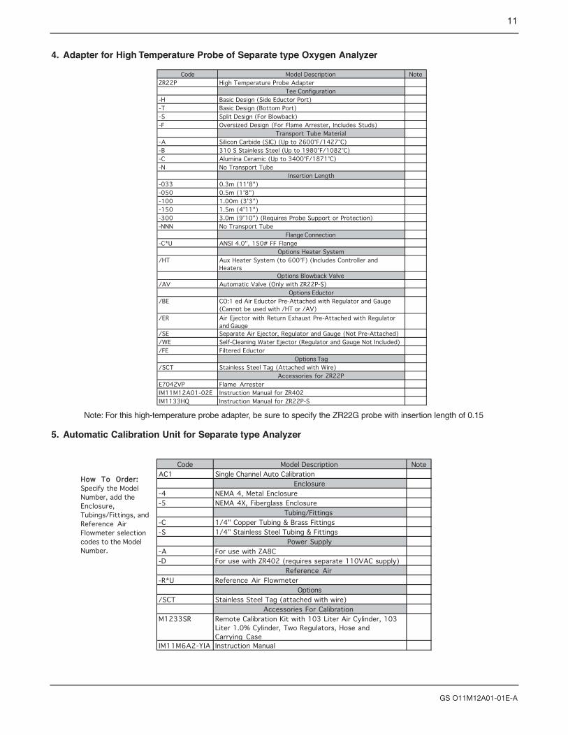
4. Adapter for High Temperature Probe of Separate type Oxygen Analyzer
Code Model Description NoteZR22P High Temperature Probe Adapter
Tee Configuration-H Basic Design (Side Eductor Port)-T Basic Design (Bottom Port)-S Split Design (For Blowback)-F Oversized Design (For Flame Arrester, Includes Studs)
Transport Tube Material-A Silicon Carbide (SIC) (Up to 2600°F/1427°C)-B 310 S Stainless Steel (Up to 1980°F/1082°C)-C Alumina Ceramic (Up to 3400°F/1871°C)-N No Transport Tube
Insertion Length-033 0.3m (11'8")-050 0.5m (1'8")-100 1.00m (3'3")-150 1.5m (4'11")-300 3.0m (9'10") (Requires Probe Support or Protection)-NNN No Transport Tube
Flange Connection-C*U ANSI 4.0", 150# FF Flange
Options Heater System/HT Aux Heater System (to 600°F) (Includes Controller and
HeatersOptions Blowback Valve
/AV Automatic Valve (Only with ZR22P-S)Options Eductor
/BE CO:1 ed Air Eductor Pre-Attached with Regulator and Gauge(Cannot be used with /HT or /AV)
/ER Air Ejector with Return Exhaust Pre-Attached with Regulatorand Gauge
/SE Separate Air Ejector, Regulator and Gauge (Not Pre-Attached)/WE Self-Cleaning Water Ejector (Regulator and Gauge Not Included)/FE Filtered Eductor
Options Tag/SCT Stainless Steel Tag (Attached with Wire)
Accessories for ZR22PE7042VP Flame ArresterIM11M12A01-02E Instruction Manual for ZR402IM1133HQ Instruction Manual for ZR22P-S
5. Automatic Calibration Unit for Separate type Analyzer
Code Model Description NoteAC1 Single Channel Auto Calibration
Enclosure-4 NEMA 4, Metal Enclosure-5 NEMA 4X, Fiberglass Enclosure
Tubing/Fittings-C 1/4" Copper Tubing & Brass Fittings-S 1/4" Stainless Steel Tubing & Fittings
Power Supply-A For use with ZA8C-D For use with ZR402 (requires separate 110VAC supply)
Reference Air-R*U Reference Air Flowmeter
Options/SCT Stainless Steel Tag (attached with wire)
Accessories For CalibrationM1233SR Remote Calibration Kit with 103 Liter Air Cylinder, 103
Liter 1.0% Cylinder, Two Regulators, Hose andCarrying Case
IM11M6A2-YIA Instruction Manual
HHooww TToo OOrrddeerr::Specify the ModelNumber, add theEnclosure,Tubings/Fittings, andReference AirFlowmeter selectioncodes to the ModelNumber.
Note: For this high-temperature probe adapter, be sure to specify the ZR22G probe with insertion length of 0.15

12
GS O11M12A01-01E-A
EXTERNAL DIMENSIONS
1. Model ZR22G Separate type Zirconia Oxygen Detector
25
t281 to 294
50
.8
12
7
85
L
48
153 to 164 69
B
A
C
F07_01.EPS
L=0.15, 0.4, 0.7, 1.0, 1.5, 2.0, 2.5, 3.03.6, 4.2, 4.8, 5.4 (m)
Rc1/4 or 1/4NPTReference air inlet
2-G1/2,2-1/2NPT etc.Cable connection port
Rc1/4 or 1/4NPTCalibration gas inlet Flange
Flange
Flange
B
A
CFlangeANSI CLASS150-2-RF equivalentANSI CLASS150-3-RF equivalentANSI CLASS150-4-RF equivalentJIS 5K-32-FF equivalentWestinghouse
152.4190.5228.6115155
120.6152.4190.5
90127
4 - 194 - 198 - 194 - 15
4 - 11.5
A B C1924245
14
t

13
GS O11M12A01-01E-A
2. Model ZR22...-P (with pressure compensated) Separate type Zirconia Oxygen Detector
25
t285 4
50
.8
12
7
85
L
48
1563 69
F07_02.EPS
L=0.15, 0.4, 0.7, 1.0, 1.5, 2.0, 2.5, 3.0 3.6, 4.2, 4.8, 5.4 (m)
C
Reference gas outlet
PIPING : A
PIPING
PIPING:B
ANSI CLASS150-2-RF equivalentANSI CLASS150-3-RF equivalentANSI CLASS150-4-RF equivalentWestinghouse
152.4190.5228.6155
120.6152.4190.5127
4 - 194 - 198 - 19
4 - 11.5
A B C19242414
ABBA
t
Rc1/4 or 1/4NPTReference air inlet
2-G1/2, 2-1/2NPT etc.Cable connection port
B
A
C
Flange
Flange
B
A
Rc1/4 or 1/4NPTCalibration gas inlet
Flange
Stop Valve
Flange

• With sun shield hood (option code /H)
14
GS O11M12A01-01E-A
3. Model ZR402G Separate type Zirconia Oxygen Converter
1 to 6 (Panel Thickness)
EXA ZR402G 4 - 6 holesfor Wall mounting
4-R8 to R10or4-C5 to C8
4 - 6 holes
8-G1/2, 8-1/2NPT etc(Wiring connection)
( for wall mounting)
F08_01.EPS
2-inch mounting pipe
Wall mounting Panel Cut-out
100
108228
280
126.
5
57.3
136.3 54.7
111
36
120.
2
(1/2
NP
T)
190 183+20
274
+2
0
126.
540 40 40
38 3824 14
36
23
ZR402G
243
4
251.
5
155.5
205.5
12355
3994
.5
4
3
4
32
2
3
F10.EPS
Material of HOOD : Aluminum

• With sun shield hood (option code /H)
15
GS O11M12A01-01E-A
4. Model ZR202G Separate type Zirconia Oxygen Analyzer
153 to 164
125
L
170252 to 265 49
48.5
338 to 351
25
t
122
L= 0.4, 0.7, 1.0, 1.5, 2.0, 2.5, 3.0 (m)
4-G1/2,2-1/2NPT etc.Cable connection port
Display side
ANSI CLASS150-2-RF equivalentANSI CLASS150-3-RF equivalentANSI CLASS150-4-RF equivalentWestinghouse
152.4190.5228.6155
120.6152.4190.5127
4 - 194 - 198 - 19
4 - 11.5
A B C19242414
t
5
0.8
Rc1/4 or 1/4NPTReference air inlet
Rc1/4 or 1/4NPTCalibration gas inlet
123
Terminal side
C
Flange
Flange
B
C
Flange
A
Flange
A
B
274 150
150
4 3
3
F13.EPS
Material of HOOD : Aluminum

16
GS O11M12A01-01E-A
5. Model ZR202G...-P (with pressure compensated) Integrated type Zirconia Oxygen Analyzer
153 to 164
125
L
170252 to 265 49
48.5
338 to 351
25
t
122
L= 0.4, 0.7, 1.0, 1.5, 2.0, 2.5, 3.0 (m)
F11_01.EPS
4-G1/2,2-1/2NPT etc.Cable connection port
Display side
ANSI CLASS150-2-RF equivalentANSI CLASS150-3-RF equivalentANSI CLASS150-4-RF equivalentWestinghouse
152.4190.5228.6155
120.6152.4190.5127
4 - 194 - 198 - 19
4 - 11.5
A B C19242414
t
5
0.8
Rc1/4 or 1/4NPTReference air inlet
Rc1/4 or 1/4NPTCalibration gas inlet
123
Terminal side
C
Flange
Flange
B
C
Flange
A
Flange
A
B

OPTIONS
1. ZR22P-H High Temperature Probe Adapter forSeparate type Oxygen Analyzer
Measuring O2 in the high temperature gases (exceeds 700°C) requires a general-use probe ZR22G of 0.15 mlength and a high-temperature probe adapter.
Sample gas temperature: 0 to 1800°C Sample gas pressure: -0.725 to 0.73 psi
(-0.725 to +36.3 requires pressurecompensation.)
Insertion length: 1 m, 1.5 mMaterial in Contact with Gas: SUS 316 (JIS), Zirconia,
SiC or SUS 310S, SUS 304 (JIS) (flange)Probe Material: SiC, SUS 310S (JIS)Installation: Flange mounting (FF type or RF type)Construction: Non explosion-proof. Rainproof
construction.Weight: Insertion length of 1.0 m: approx. 6.5 kg (JIS) /
approx. 8.5 kg (ANSI)Insertion length of 1.5m: approx. 7.5 kg (JIS) / approx.
9.5 kg (ANSI)
2. ZR22R Probe Protector for Zirconia OxygenAnalyzer
Used when sample gas flow velocity is approx. 10m/sec ormore and dust particles wears the detector in cases suchas pulverized coal boiler of fluidized bed furnace (or burner).When probe insertion length is 2.5 m or more andhorizontal installation, specify the ZR22V to reinforce theprobe.
Insertion Length: 1.5 m, 1.55 m, 2.05 m.Flange: JIS 5K 65A FF equivalent. ANSI CLASS 150-4-
FF (without serration) equivalent or DIN PN10-DN50-A equivalent. However, flange thickness isdifferent.
Material: SUS316 (JIS), SUS304 (JIS) (Flange)Weight: 1.05 m; Approx. 6/10/8.5 kg (JIS/ANSI/DlN),
1.55 m; Approx. 9/13/11.5 kg (JIS/ANSI/DIN), 2.05 m; Approx. 12/16/14.5 kg (JIS/ANSI/DIN)
17
GS O11M12A01-01E-A
6. Model ZR22P Adapter for High Temperature Probe of Separate type Oxygen Analyzer
Rc 1/4
1/4 FNPTF12A.EPS
1/2 FNPT
Approx. 351
180 Flange (Thickness)JIS 5K 32A FF equivalent
Gasket (Thickness 3)
Detector(ZR22G)
Flange <1>
52 over
30
60.5
Reference air inlet <2>
Calibration gas inlet<3>
High temperatureProbe SiC pipe
110
115
4225
170
App
rox,
215
(Ins
etio
n le
ngth
) (N
ote1
)
App
rox,
100
69
C (Note 1) 1=1000 or 1500 (mm)(Note 2) Sample gas outlet
(if the sample gas pressure is negative, connect the auxiliary ejector.)
127
85
Measurement gas outlet
Flange providedby customer
Unit: mm
60.5A
B
A
<1> Flange
JIS 5K-50-FF equivalent 130
228.6
105
190.5
4 - 15
8 - 19
<2>,<3> joint A B C
ANSI CLASS150-4-RF equivalent
Pipe hole (2-1/2NPT, etc)
Flange<1>
JIS 5K-65-FFequivalent
155
228.6
130
190.5
4- 15
8- 19
5
12
A B C t
ANSI CLASS150-4-FF equivalent
40
50
D
F17.EPS
D
C
B
B
Flange <1>(with bolts, nuts, gasket and washer)
gasket (t1.5)
SUS316
Dimensions ofholes on opposing surface
A
Gas flow
Washer (12)Mounting nut (M12)
l (Insert length)
l=1050,1550,2050
60.5

3. Filter for Oxygen Analyzer E7042UQThis filter is used to protect the cell from corrosive dustcomponents in natural gas or oil applications. Measuredgas flow rate is needed to be 1m/sec or more to replacegas inside zirconia sensor.
Mesh: 30 micronsMaterial: Carborundum (Filter), SUS316 (JIS)Weight: Approx. 0.2kg
4. M1200DB-06 Hastelloy X Sintered FilterAssembly (for use with ZR22G)
This filter addresses blockage and coating problemsexperienced by tough applications.
Mesh: 10 microns (filter)Material: Hastelloy XMaximum Temperature Rating: 1292°F (700°C)Connection: Stainless Steel c-clamp with boltsWeight: Approximately 18 lb (.8kg)
5. K9292DS Check ValveThe check valve prevents the water vapor in the processfrom diffusing down the calibration line where it maycondense and cause the cell to crack. A check valveshould be used on all natural gas and positive pressureapplications and any time a cal line is installed with longperiods (>3 months) of time time between calibrations.
Connection: 1/4 FNPT inlet; 1/4” MNPT outletMaterial: 304SSCracking Pressure: 1 psiWeight: Approximately 0.1lb (50g)
Note: The check valve is not a substitution for an inlinefilter for removing moisture from instrument air source.
6. Auxiliary Ejector Assembly, Model No.M1132KEHigh temperature installations require the use of theauxiliary ejector assembly in all installations. usinginstrument air, the auxiliary ejector draws a sample through
the adapter tee for quick measurement without mechanicalassistance. The assembly includes an ejector, regulatorand pressure gauge and is included in the heated eductor(/BE or /ER option) for the ZR22P high temperatureadapter tee.Note: Positive pressure requires the use of a needle valveto restrict the flow of sample gas.
7. Ejector, Model No. M1132KAThe ejector induces flow of the sample from the processthrough the transport tube. The draft causes the sampleflow from the process to pulled through a high temperatureadapter tee (i.e. transport tube).
Material: 316SSAir Supply: 1/8” NPT femaleExhaust: 1/8” NPT male straightVacuum Force: 7.6” HgVacuum Flow: 2.4 SCFMAir Consumption: 1.7 SCFMWeight: 6oz (170g)Vacuum: 1/8” NPT male
Pressure Regulator, Model no. M1132KDThis general purpose regulator is used to adjust the flow ofinstrument air entering the ejector. Made of durablematerials and corrosion resistant construction, it providesreliable operation in harsh industrial environments.
Flow Capacity: 20SCFM (33.6 m3/hr) at 100psig (700 kPa) supply - 20 psig (140 kPa) outlet.
Exhaust Capacity: 0.1 SCFM (0.17 m3/hr) -downstream pressure 5 psig (35 kPa) abovesetpoint.
Sensitivity: 1” (2.5 cm) of waterEffect of Supply Pressure Variation: Less than 0.2 psig
(1.4 kPa) for 25 psi (170 kPa) change.Maximum Supply Pressure: 250 psig (1700 kPa)Air Consumption: Less than 6 SCFH (0.17 m3/hr)Output Range: 0 to 60 psi ( 0 to 400 kPa)Port Size: 1/4” NPTMaterials: Body - Die cast aluminum alloy; Diaphragm -
Nitrile elastomer and nylon fabric; Trim - Brass,zinc plated steel, acetal.
Weight: 4.0lb (1.8kg)
18
GS O11M12A01-01E-A
K9292DN : Rc 1/4(A),R 1/4(B)K9292DS : 1/4FNPT(A),1/4NPT(Mail)(B)
F30.EPS
Approx. 19 Approx. 54
Unit: mm
0 30
25
20
15
10
5
BAR100 x kPa
psi
0.5
1.0
1.5
2.0
2.50
[63.5]
5.63
[143.0]
IN
IN
FROM PROBE ADAPTER
1/4 NPTFEMALE 1/4 NPT
FEMALE
1/8 NPTFEMALE
(2) 10-24 UNCMOUNTING HOLES
OUT
EXHAUST
1/4 NPT MALE(TYP EA END)
EX
HA
US
TS
AM
PLE
ZA8A09.EPS
(REF)2.83
8.10
(REF)
(REF)
END OF O PROBE2
7.0
THIS VIEW SHOWS THE
AS IT IS INSTALLED.(PROCESS FLOW WILL BE DOWN)
SIDE VIEW OF THE FILTER
FLOW
C-CLAMP CONNECTION
ZA8A10 2drawing.eps

19
GS O11M12A01-01E-A
9. Model AR20H Automatic Calibration Unit for Integrated type Analyzer
zero gas inlet
Rc1/4 or 1/4NPT(Female)
reference air inlet
Rc1/4 or 1/4NPT(Female)
terminal box side
span gas inlet
Rc1/4 or 1/4NPT(Female)
166.5
258
244
214 MAX44 66.540 40
Vertical mounting on the ZR202G (-B)
F36.EPS
Horizontal mounting on the ZR202G (-A)Unit: mm
display side
zero gas inlet
Rc1/4 or 1/4NPT(Female)
Span gas inlet
Rc1/4 or 1/4NPT(Female)
reference air inlet
Rc1/4 or 1/4NPT(Female)
166.5
604516
0
66.540 40180 MAX44

20
GS O11M12A01-01E-A
WIRING CONNECTIONS
1FG
2AO1(+)
3AO1(-)
4AO2(+)
5AO2(-)
6CJ(+)
7CJ(-)
8TC(+)
9TC(-)
10CELL
(+)
11CELL
(-)12FG
13DI-1
14DI-2
15DI-C
16AI(+)
17AI(-)
18AC-
ZERO
19AC-
SPAN
20AC-
COM
21FG
22FG
CELL(+)
CELL(-)
TC(+)
TC(-)
CJ(+)
CJ(-)
23DO-1
24DO-1
25DO-2
26DO-2
27DO-3
28DO-3
29DO-4
30DO-4
31HTR
32HTR
33L
34N
35G
36FG HTR HTR
100-240V AC50/60 Hz
F27.EPS
Model ZR402G Separate type Zirconia Oxygen Analyzer/ High Temperature Humidity Analyzer, Converter
Model ZR22G Separate type Zirconia Oxygen /High Temperature Humidity Analyzer, Detector
Analog output 2
Analog output 1
4-20 mA DC4-20 mA DCDigital output
Contact input 2
Contact input 1
Contact output 1
Contact output 2
Contact output 3
Contact output 4
Temperature transmitter input 4-20 mA DC
Solenoid valve for automatic calibration
Span gas
Solenoid valve for zero gas for automatic calibration
Flow setting meter
*1
*1
*2
*1 Grand resistance is 100 ohm or less.*2 Option (Temperrature transmitter provide by user) for humidity measurement.
1DI-1
2DI-2
3DI-C
4DO-1
5DO-1
6DO-2
7DO-2
8FG
9AO(+)
10AO(-)
11L
12N
13G
14FG
F28.EPS
Model ZR202G Integrated type Zirconia Oxygen / High Temperature Humidity Analyzer
Contact input 1Contact output 2Contact output 1
Analog output 4-20 mA DC
100 to 240 V AC, 50 or 60 Hz
Digital output
Contact input 2
*1
*1 Ground resistance is 100 ohm or less.