general troubleshooting schematic -...
TRANSCRIPT
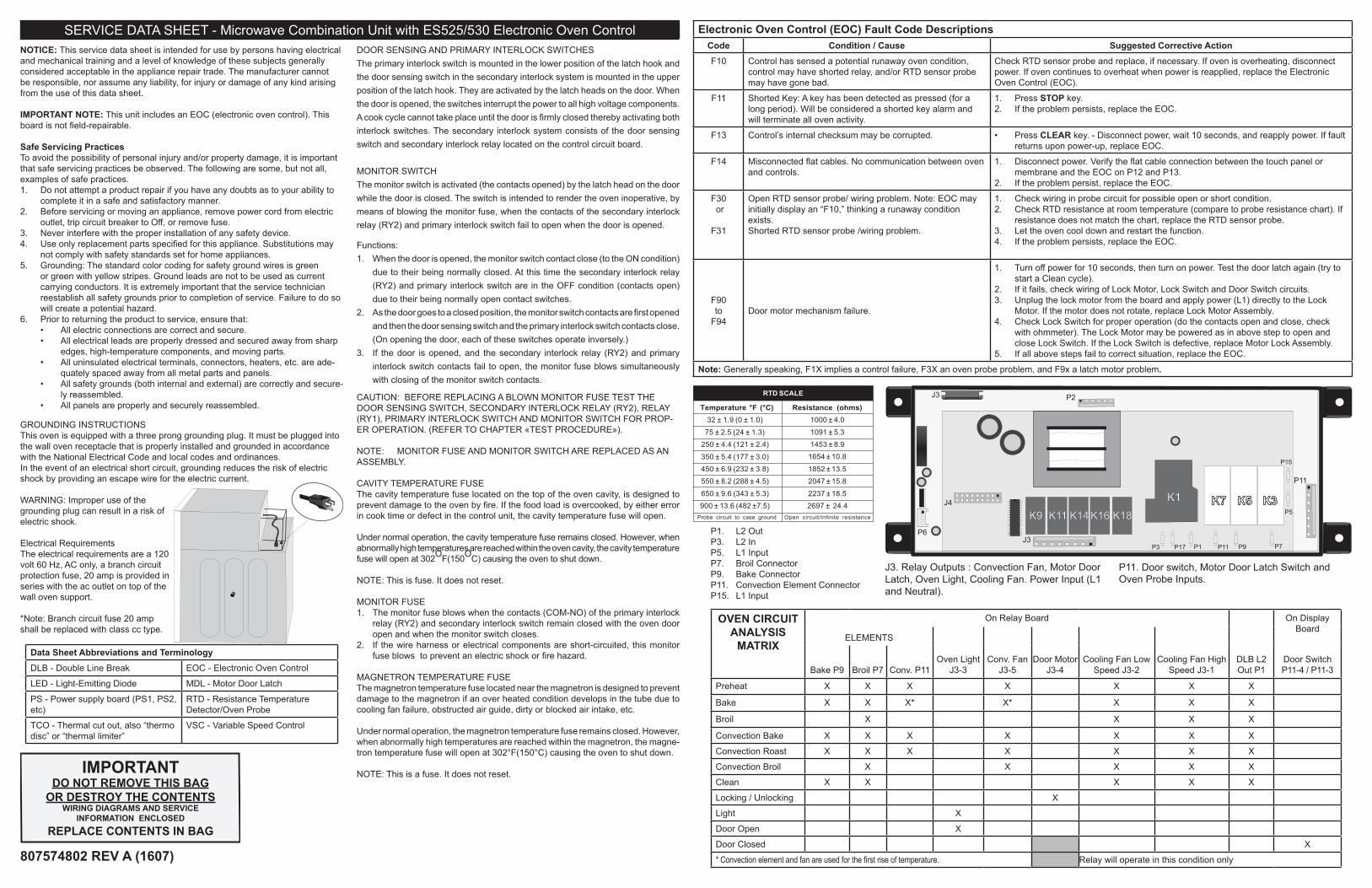
Electronic Oven Control (EOC) Fault Code DescriptionsCode Condition / Cause Suggested Corrective ActionF10 Control has sensed a potential runaway oven condition,
control may have shorted relay, and/or RTD sensor probe may have gone bad.
Check RTD sensor probe and replace, if necessary. If oven is overheating, disconnect power. If oven continues to overheat when power is reapplied, replace the Electronic Oven Control (EOC).
F11 Shorted Key: A key has been detected as pressed (for a long period). Will be considered a shorted key alarm and will terminate all oven activity.
1. Press STOP key.2. If the problem persists, replace the EOC.
F13 Control’s internal checksum may be corrupted. • Press CLEAR key. - Disconnect power, wait 10 seconds, and reapply power. If fault returns upon power-up, replace EOC.
F14 Misconnected flat cables. No communication between oven and controls.
1. Disconnect power. Verify the flat cable connection between the touch panel or membrane and the EOC on P12 and P13.
2. If the problem persist, replace the EOC.
F30 or
F31
Open RTD sensor probe/ wiring problem. Note: EOC may initially display an “F10,” thinking a runaway condition exists.Shorted RTD sensor probe /wiring problem.
1. Check wiring in probe circuit for possible open or short condition.2. Check RTD resistance at room temperature (compare to probe resistance chart). If
resistance does not match the chart, replace the RTD sensor probe.3. Let the oven cool down and restart the function.4. If the problem persists, replace the EOC.
F90to
F94Door motor mechanism failure.
1. Turn off power for 10 seconds, then turn on power. Test the door latch again (try to start a Clean cycle).
2. If it fails, check wiring of Lock Motor, Lock Switch and Door Switch circuits.3. Unplug the lock motor from the board and apply power (L1) directly to the Lock
Motor. If the motor does not rotate, replace Lock Motor Assembly.4. Check Lock Switch for proper operation (do the contacts open and close, check
with ohmmeter). The Lock Motor may be powered as in above step to open and close Lock Switch. If the Lock Switch is defective, replace Motor Lock Assembly.
5. If all above steps fail to correct situation, replace the EOC.
Note: Generally speaking, F1X implies a control failure, F3X an oven probe problem, and F9x a latch motor problem.
NOTICE: This service data sheet is intended for use by persons having electrical and mechanical training and a level of knowledge of these subjects generally considered acceptable in the appliance repair trade. The manufacturer cannot be responsible, nor assume any liability, for injury or damage of any kind arising from the use of this data sheet.
IMPORTANT NOTE: This unit includes an EOC (electronic oven control). This board is not field-repairable.
Safe Servicing PracticesTo avoid the possibility of personal injury and/or property damage, it is important that safe servicing practices be observed. The following are some, but not all, examples of safe practices.1. Do not attempt a product repair if you have any doubts as to your ability to
complete it in a safe and satisfactory manner.2. Before servicing or moving an appliance, remove power cord from electric
outlet, trip circuit breaker to Off, or remove fuse.3. Never interfere with the proper installation of any safety device.4. Use only replacement parts specified for this appliance. Substitutions may
not comply with safety standards set for home appliances.5. Grounding: The standard color coding for safety ground wires is green
or green with yellow stripes. Ground leads are not to be used as current carrying conductors. It is extremely important that the service technician reestablish all safety grounds prior to completion of service. Failure to do so will create a potential hazard.
6. Prior to returning the product to service, ensure that:• All electric connections are correct and secure.• All electrical leads are properly dressed and secured away from sharp
edges, high-temperature components, and moving parts.• All uninsulated electrical terminals, connectors, heaters, etc. are ade-
quately spaced away from all metal parts and panels.• All safety grounds (both internal and external) are correctly and secure-
ly reassembled.• All panels are properly and securely reassembled.
IMPORTANTDO NOT REMOVE THIS BAG
OR DESTROY THE CONTENTSWIRING DIAGRAMS AND SERVICE
INFORMATION ENCLOSEDREPLACE CONTENTS IN BAG
Resistance (ohms)1000 ± 4.0
1091 ± 5.3
1453 ± 8.9
1654 ± 10.8
1852 ± 13.5
2047 ± 15.8
2237 ± 18.5
2697 ± 24.4Open circuit/infinite resistance
RTD SCALE
Temperature °F (°C)32 ± 1.9 (0 ± 1.0)
75 ± 2.5 (24 ± 1.3)
250 ± 4.4 (121 ± 2.4)
350 ± 5.4 (177 ± 3.0)
450 ± 6.9 (232 ± 3.8)
550 ± 8.2 (288 ± 4.5)
650 ± 9.6 (343 ± 5.3)
900 ± 13.6 (482 ±7.5)Probe circuit to case ground
807574802 REV A (1607)
SERVICE DATA SHEET - Microwave Combination Unit with ES525/530 Electronic Oven Control
GROUNDING INSTRUCTIONS This oven is equipped with a three prong grounding plug. It must be plugged into the wall oven receptacle that is properly installed and grounded in accordance with the National Electrical Code and local codes and ordinances. In the event of an electrical short circuit, grounding reduces the risk of electric shock by providing an escape wire for the electric current.
WARNING: Improper use of the grounding plug can result in a risk of electric shock.
Electrical RequirementsThe electrical requirements are a 120 volt 60 Hz, AC only, a branch circuit protection fuse, 20 amp is provided in series with the ac outlet on top of the wall oven support.
*Note: Branch circuit fuse 20 amp shall be replaced with class cc type.
OVEN CIRCUIT ANALYSIS
MATRIX
On Relay Board On Display Board
ELEMENTS
Oven Light J3-3
Conv. Fan J3-5
Door MotorJ3-4
Cooling Fan Low Speed J3-2
Cooling Fan High Speed J3-1
DLB L2 Out P1Bake P9 Broil P7 Conv. P11
Door Switch P11-4 / P11-3
Preheat X X X X X X X
Bake X X X* X* X X X
Broil X X X X
Convection Bake X X X X X X X
Convection Roast X X X X X X X
Convection Broil X X X X X
Clean X X X X X
Locking / Unlocking X
Light X
Door Open X
Door Closed X
* Convection element and fan are used for the first rise of temperature. Relay will operate in this condition only
J4
P11 P9 P7J3
K11 K14 K16 K18K7 K5 K3
P5
P6
P11
P15
K9
J3 P2
K1
P3 P17 P1
DOOR SENSING AND PRIMARY INTERLOCK SWITCHESThe primary interlock switch is mounted in the lower position of the latch hook and the door sensing switch in the secondary interlock system is mounted in the upper position of the latch hook. They are activated by the latch heads on the door. When the door is opened, the switches interrupt the power to all high voltage components. A cook cycle cannot take place until the door is firmly closed thereby activating both interlock switches. The secondary interlock system consists of the door sensing switch and secondary interlock relay located on the control circuit board.
MONITOR SWITCHThe monitor switch is activated (the contacts opened) by the latch head on the door while the door is closed. The switch is intended to render the oven inoperative, by means of blowing the monitor fuse, when the contacts of the secondary interlock relay (RY2) and primary interlock switch fail to open when the door is opened.
Functions:1. When the door is opened, the monitor switch contact close (to the ON condition)
due to their being normally closed. At this time the secondary interlock relay (RY2) and primary interlock switch are in the OFF condition (contacts open) due to their being normally open contact switches.
2. As the door goes to a closed position, the monitor switch contacts are first opened and then the door sensing switch and the primary interlock switch contacts close. (On opening the door, each of these switches operate inversely.)
3. If the door is opened, and the secondary interlock relay (RY2) and primary interlock switch contacts fail to open, the monitor fuse blows simultaneously with closing of the monitor switch contacts.
CAUTION: BEFORE REPLACING A BLOWN MONITOR FUSE TEST THE DOOR SENSING SWITCH, SECONDARY INTERLOCK RELAY (RY2), RELAY (RY1), PRIMARY INTERLOCK SWITCH AND MONITOR SWITCH FOR PROP-ER OPERATION. (REFER TO CHAPTER «TEST PROCEDURE»).
NOTE: MONITOR FUSE AND MONITOR SWITCH ARE REPLACED AS AN ASSEMBLY.
CAVITY TEMPERATURE FUSEThe cavity temperature fuse located on the top of the oven cavity, is designed to prevent damage to the oven by fire. If the food load is overcooked, by either error in cook time or defect in the control unit, the cavity temperature fuse will open.
Under normal operation, the cavity temperature fuse remains closed. However, when abnormally high temperatures are reached within the oven cavity, the cavity temperature fuse will open at 302OF(150OC) causing the oven to shut down.
NOTE: This is fuse. It does not reset.
MONITOR FUSE1. The monitor fuse blows when the contacts (COM-NO) of the primary interlock
relay (RY2) and secondary interlock switch remain closed with the oven door open and when the monitor switch closes.
2. If the wire harness or electrical components are short-circuited, this monitor fuse blows to prevent an electric shock or fire hazard.
MAGNETRON TEMPERATURE FUSEThe magnetron temperature fuse located near the magnetron is designed to prevent damage to the magnetron if an over heated condition develops in the tube due to cooling fan failure, obstructed air guide, dirty or blocked air intake, etc.
Under normal operation, the magnetron temperature fuse remains closed. However, when abnormally high temperatures are reached within the magnetron, the magne-tron temperature fuse will open at 302°F(150°C) causing the oven to shut down.
NOTE: This is a fuse. It does not reset.
Data Sheet Abbreviations and TerminologyDLB - Double Line Break EOC - Electronic Oven Control
LED - Light-Emitting Diode MDL - Motor Door Latch
PS - Power supply board (PS1, PS2, etc)
RTD - Resistance Temperature Detector/Oven Probe
TCO - Thermal cut out, also “thermo disc” or “thermal limiter”
VSC - Variable Speed Control
J3. Relay Outputs : Convection Fan, Motor Door Latch, Oven Light, Cooling Fan. Power Input (L1 and Neutral).
P11. Door switch, Motor Door Latch Switch and Oven Probe Inputs.
P1. L2 OutP3. L2 InP5. L1 InputP7. Broil ConnectorP9. Bake ConnectorP11. Convection Element ConnectorP15. L1 Input
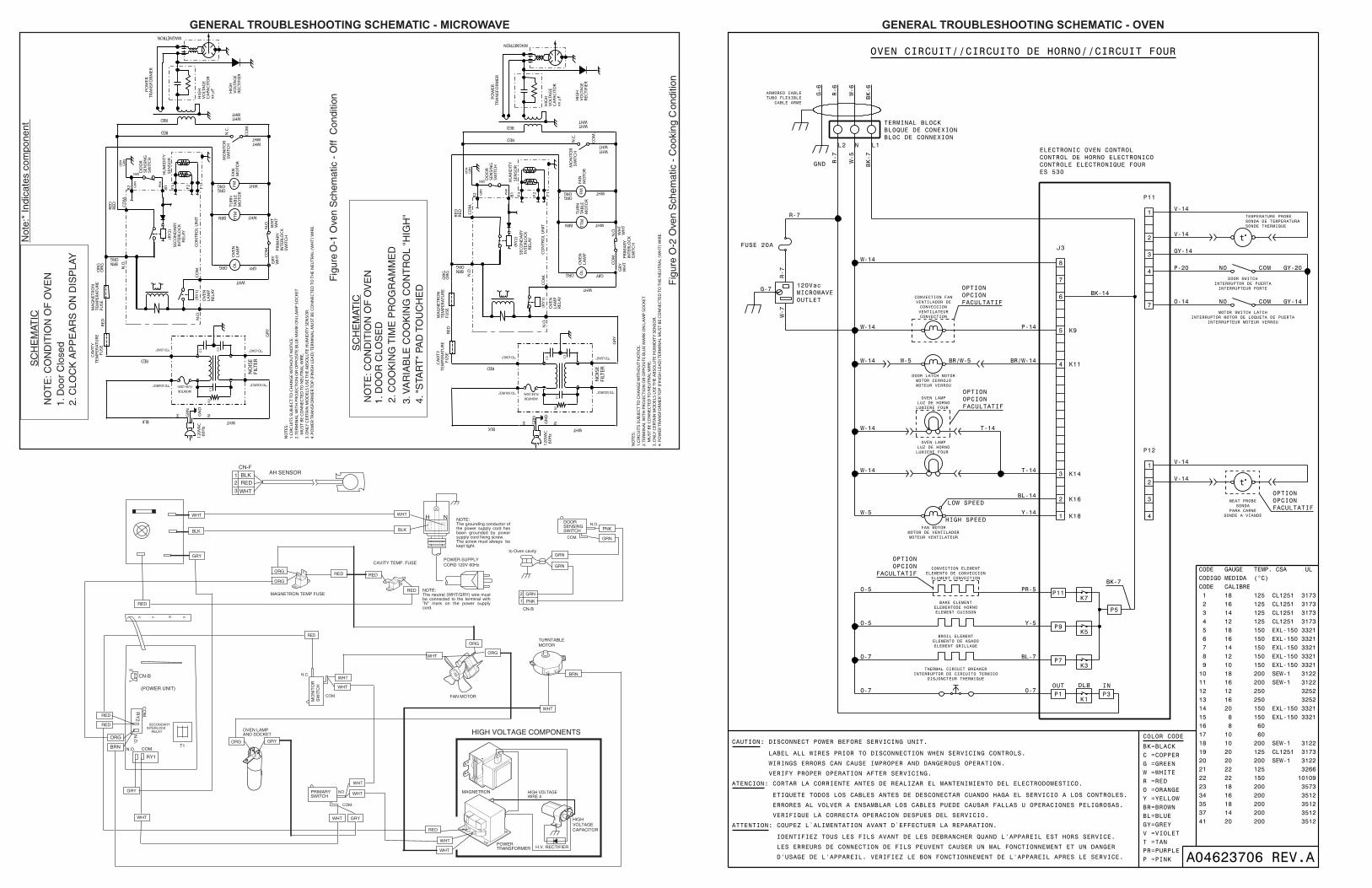
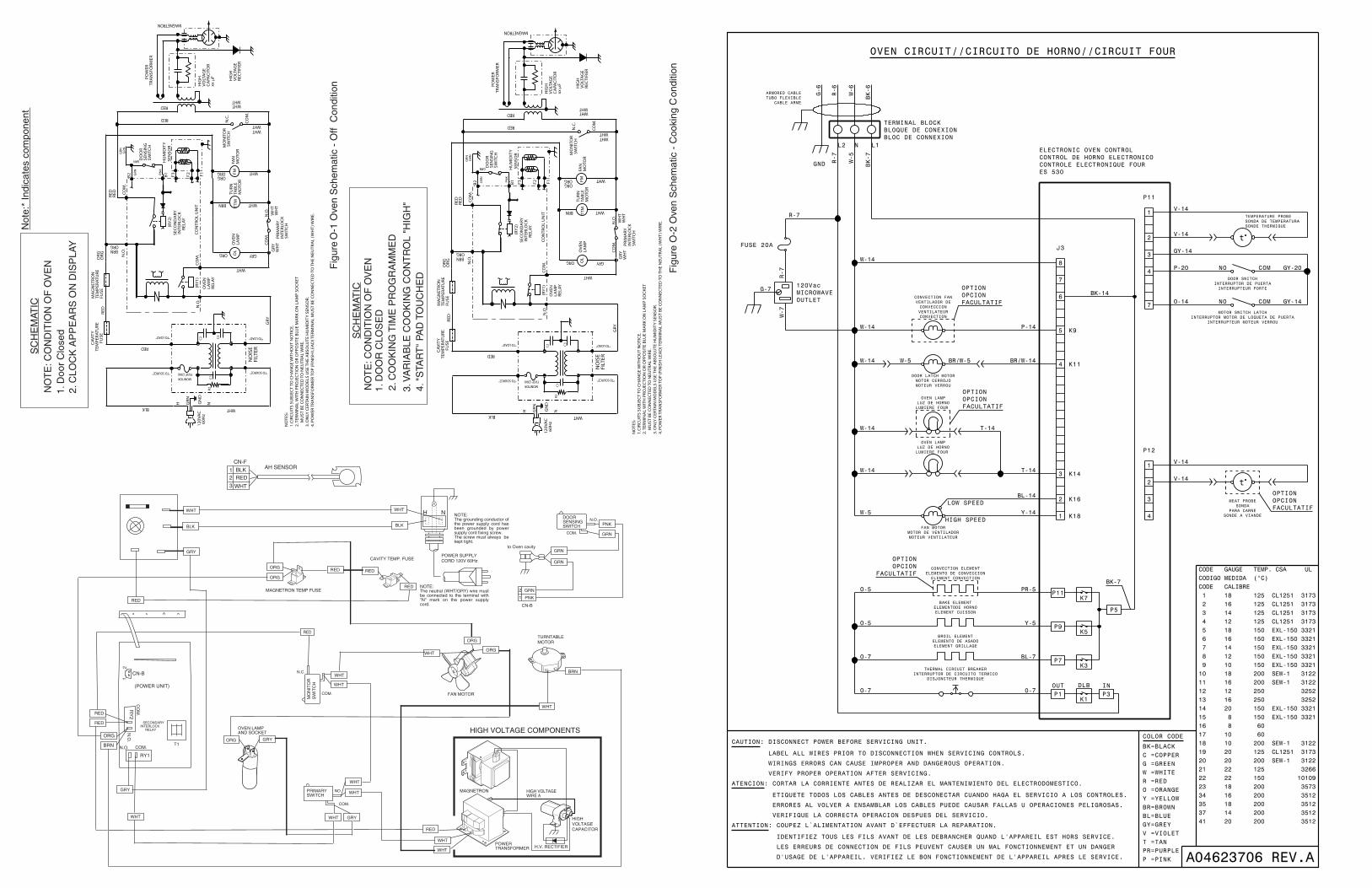
GENERAL TROUBLESHOOTING SCHEMATIC - OVEN
Figu
re O
-2 O
ven
Sch
emat
ic -
Coo
king
Con
ditio
n
Fig
ure
O-1
Ove
n S
chem
atic
- O
ff C
ondi
tion
SC
HE
MAT
ICN
OT
E: C
ON
DIT
ION
OF
OV
EN
1. D
oor
Clo
sed
2. C
LOC
K A
PP
EA
RS
ON
DIS
PLA
Y
SC
HE
MAT
IC
3. V
AR
IAB
LE C
OO
KIN
G C
ON
TR
OL
"HIG
H"
2. C
OO
KIN
G T
IME
PR
OG
RA
MM
ED
1. D
OO
R C
LOS
ED
NO
TE
: CO
ND
ITIO
N O
F O
VE
N
4. "
STA
RT
" PA
D T
OU
CH
ED
Not
e:*
Indi
cate
s co
mpo
nent
NO
TE
S:
1.C
IRC
UIT
S S
UB
JEC
T T
O C
HA
NG
E W
ITH
OU
T N
OT
ICE
.2
. TE
RM
INA
L W
ITH
PR
OJE
CT
ION
OR
OP
PO
SIT
E B
LUE
MA
RK
ON
LA
MP
SO
CK
ET
M
US
T B
E C
ON
NE
CT
ED
TO
NE
UT
RA
L W
IRE
.3
. ON
LY C
ER
TAIN
MO
DE
LS U
SE
TH
E A
BS
OLU
TE
HU
MID
ITY
SE
NS
OR
.4
. PO
WE
R T
RA
NS
FOR
ME
R T
OP
(FI
NIS
H L
EA
D) T
ER
MIN
AL
MU
ST
BE
CO
NN
EC
TE
D T
O T
HE
NE
UT
RA
L (W
HT
) WIR
E.
CA
VIT
Y
TE
MP
ER
AT
UR
E
F
US
E
12
0VA
C 6
0H
z
CO
M.
RED
RED
WH
TW
HT
WHT
GRY
BRN
WHT
WHT
WH
T
ORG
RED
WHT
WHT
GR
N
N.O
.
B2 B1
CO
NT
RO
L U
NIT
MA
GN
ET
RO
NT
EM
PE
RA
TU
RE
FUS
E
N.O
.
(RY
2)
CO
M.
DO
OR
SE
NS
ING
SW
ITC
H
TT
MFM
OL
TU
RN
TAB
LEM
OTO
R
FAN
MO
TOR
OV
EN
LAM
P
MO
NIT
OR
SW
ITC
H
PR
IMA
RY
INT
ER
LOC
KS
WIT
CH
PO
WE
RT
RA
NS
FOR
ME
R
MAGNETRON
HIG
HV
OLT
AG
EC
APA
CIT
OR
xx µ
F
ORG
WHT
SE
CO
ND
AR
Y IN
TE
RLO
CK
R
ELA
Y
ORGBRN
OR
GO
RG
RE
D
GR
YG
RY
GN
D
WHT
F3 F2 F1
SE
NS
OR
(RY
1)
OV
EN
LAM
PR
ELA
Y
CO
M.
N.O
.
HU
MID
ITY
CO
M.
N.C
.H
IGH
VO
LTA
GE
RE
CT
IFIE
R
ORG
H N
RE
DR
ED
PN
K
GR
N
GRN
GR
NG
RN
C3
C2
C1
BLK
WHT
NO
ISE
FILT
ER
MONITORFUSE (20A)
R2
"TO LOAD" "TO LOAD"
"TO SOURCE""TO SOURCE"
NO
TE
S:
1.C
IRC
UIT
S S
UB
JEC
T T
O C
HA
NG
E W
ITH
OU
T N
OT
ICE
.2
. TE
RM
INA
L W
ITH
PR
OJE
CT
ION
OR
OP
PO
SIT
E B
LUE
MA
RK
ON
LA
MP
SO
CK
ET
M
US
T B
E C
ON
NE
CT
ED
TO
NE
UT
RA
L W
IRE
.3
. ON
LY C
ER
TAIN
MO
DE
LS U
SE
TH
E A
BS
OLU
TE
HU
MID
ITY
SE
NS
OR
.4
. PO
WE
R T
RA
NS
FOR
ME
R T
OP
(FI
NIS
H L
EA
D) T
ER
MIN
AL
MU
ST
BE
CO
NN
EC
TE
D T
O T
HE
NE
UT
RA
L (W
HT
) WIR
E.
CA
VIT
Y
TE
MP
ER
AT
UR
E
F
US
E
12
0VA
C 6
0H
z
CO
M.
RED
RED
WH
TW
HT
WHT
GRY
BRN
WHT
WHT
WH
T
ORG
RED
WHT
WHT
GR
N
N.O
.
B2 B1
CO
NT
RO
L U
NIT
MA
GN
ET
RO
NT
EM
PE
RA
TU
RE
FUS
E
N.O
.
(RY
2)
CO
M.
DO
OR
SE
NS
ING
SW
ITC
H
TT
MFM
OL
TU
RN
TAB
LEM
OTO
R
FAN
MO
TOR
OV
EN
LAM
P
MO
NIT
OR
SW
ITC
H
PR
IMA
RY
INT
ER
LOC
KS
WIT
CH
PO
WE
RT
RA
NS
FOR
ME
R
MAGNETRON
HIG
HV
OLT
AG
EC
APA
CIT
OR
xx µ
F
ORG
WHT
SE
CO
ND
AR
Y IN
TE
RLO
CK
R
ELA
Y
ORGBRN
OR
GO
RG
RE
D
GR
YG
RY
GN
D
WHT
F3 F2 F1
SE
NS
OR
(RY
1)
OV
EN
LAM
PR
ELA
Y
CO
M.
N.O
.
HU
MID
ITY
CO
M.
N.C
.H
IGH
VO
LTA
GE
RE
CT
IFIE
R
ORG
H N
RE
DR
ED
PN
K
GR
N
GRN
GR
NG
RN
C3
C2
C1
BLK
WHTN
OIS
EFI
LTE
R
MONITORFUSE (20A)
R2
"TO LOAD" "TO LOAD"
"TO SOURCE""TO SOURCE"
GENERAL TROUBLESHOOTING SCHEMATIC - MICROWAVE
HIGH VOLTAGECAPACITOR
HIGH VOLTAGEWIRE A
H.V. RECTIFIER
HIGH VOLTAGE COMPONENTSOVEN LAMP AND SOCKET
MAGNETRON
COM.
MO
NIT
OR
SW
ITC
H
N.C.
PRIMARYSWITCH
TURNTABLEMOTOR
POWER TRANSFORMER
COM.
NO
WHT
RED
RED
ORG GRY
ORG
WHT
WHT
WHT
RED
RED
CAVITY TEMP. FUSE
MAGNETRON TEMP FUSE
FAN MOTOR
RED
WHT
WHT
POWER SUPPLY CORD 120V 60Hz
NOTE:The neutral (WHT/GRY) wire must be connected to the terminal with "N" mark on the power supply cord.
BLK
WHT H N NOTE:The grounding conductor of the power supply cord has been grounded by power supply cord fixing screw.The screw must always be kept tight.
COM.
N.O.DOORSENSINGSWITCH PNK
GRN
GRNto Oven cavity
GRN
PNK
GRN2
1
CN-B
BRN
WHT
ORG
RED
GRY
WHT
BLK
RED
COM.
CO
M.
.O.N
N.O
.
1YR
RY
2
YRADNOCES KCOLRETNI
YALER
T1
12
)TINU REWOP(
B-NC
GRO
WHT
GRY
ORG
ORG
WHT
GRY
WHT
RED
NRB
BLK AH SENSOR
RED
WHT
12
3
CN-F
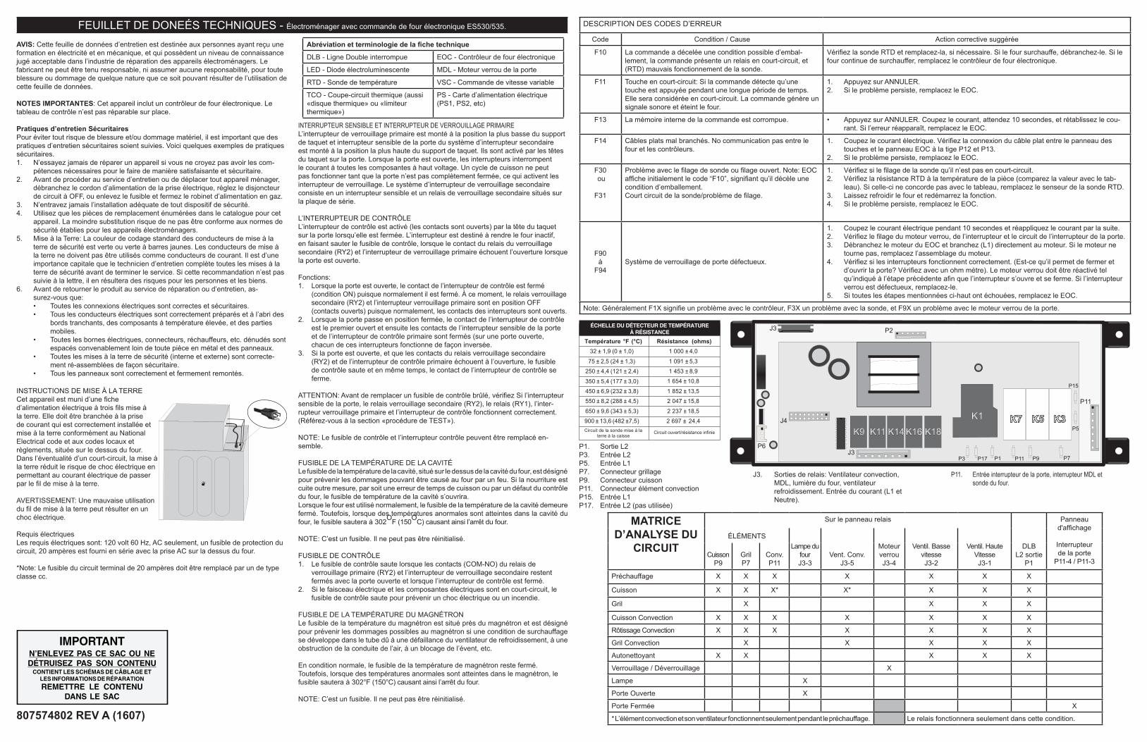
DESCRIPTION DES CODES D’ERREUR
Code Condition / Cause Action corrective suggérée
F10 La commande a décelée une condition possible d’embal-lement, la commande présente un relais en court-circuit, et (RTD) mauvais fonctionnement de la sonde.
Vérifiez la sonde RTD et remplacez-la, si nécessaire. Si le four surchauffe, débranchez-le. Si le four continue de surchauffer, remplacez le contrôleur de four électronique.
F11 Touche en court-circuit: Si la commande détecte qu’une touche est appuyée pendant une longue période de temps. Elle sera considérée en court-circuit. La commande génère un signale sonore et éteint le four.
1. Appuyez sur ANNULER.2. Si le problème persiste, remplacez le EOC.
F13 La mémoire interne de la commande est corrompue. • Appuyez sur ANNULER. Coupez le courant, attendez 10 secondes, et rétablissez le cou-rant. Si l’erreur réapparaît, remplacez le EOC.
F14 Câbles plats mal branchés. No communication pas entre le four et les contrôleurs.
1. Coupez le courant électrique. Vérifiez la connexion du câble plat entre le panneau des touches et le panneau EOC à la tige P12 et P13.
2. Si le problème persiste, remplacez le EOC.
F30 ou
F31
Problème avec le filage de sonde ou filage ouvert. Note: EOC affiche initialement le code “F10”, signifiant qu’il décèle une condition d’emballement.Court circuit de la sonde/problème de filage.
1. Vérifiez si le filage de la sonde qu’il n’est pas en court-circuit.2. Vérifiez la résistance RTD à la température de la pièce (comparez la valeur avec le tab-
leau). Si celle-ci ne concorde pas avec le tableau, remplacez le senseur de la sonde RTD.3. Laissez refroidir le four et redémarrez la fonction.4. Si le problème persiste, remplacez le EOC.
F90à
F94Système de verrouillage de porte défectueux.
1. Coupez le courant électrique pendant 10 secondes et réappliquez le courant par la suite.2. Vérifiez le filage du moteur verrou, de l’interrupteur et le circuit de l’interrupteur de la porte.3. Débranchez le moteur du EOC et branchez (L1) directement au moteur. Si le moteur ne
tourne pas, remplacez l’assemblage du moteur.4. Vérifiez si les interrupteurs fonctionnent correctement. (Est-ce qu’il permet de fermer et
d’ouvrir la porte? Vérifiez avec un ohm mètre). Le moteur verrou doit être réactivé tel qu’indiqué à l’étape précédente afin que l’interrupteur s’ouvre et se ferme. Si l’interrupteur verrou est défectueux, remplacez-le.
5. Si toutes les étapes mentionnées ci-haut ont échouées, remplacez le EOC.
Note: Généralement F1X signifie un problème avec le contrôleur, F3X un problème avec la sonde, et F9X un problème avec le moteur verrou de la porte.
AVIS: Cette feuille de données d’entretien est destinée aux personnes ayant reçu une formation en électricité et en mécanique, et qui possèdent un niveau de connaissance jugé acceptable dans l’industrie de réparation des appareils électroménagers. Le fabricant ne peut être tenu responsable, ni assumer aucune responsabilité, pour toute blessure ou dommage de quelque nature que ce soit pouvant résulter de l’utilisation de cette feuille de données.
NOTES IMPORTANTES: Cet appareil inclut un contrôleur de four électronique. Le tableau de contrôle n’est pas réparable sur place.
Pratiques d’entretien SécuritairesPour éviter tout risque de blessure et/ou dommage matériel, il est important que des pratiques d’entretien sécuritaires soient suivies. Voici quelques exemples de pratiques sécuritaires.1. N’essayez jamais de réparer un appareil si vous ne croyez pas avoir les com-
pétences nécessaires pour le faire de manière satisfaisante et sécuritaire.2. Avant de procéder au service d’entretien ou de déplacer tout appareil ménager,
débranchez le cordon d’alimentation de la prise électrique, réglez le disjoncteur de circuit à OFF, ou enlevez le fusible et fermez le robinet d’alimentation en gaz.
3. N’entravez jamais l’installation adéquate de tout dispositif de sécurité.4. Utilisez que les pièces de remplacement énumérées dans le catalogue pour cet
appareil. La moindre substitution risque de ne pas être conforme aux normes de sécurité établies pour les appareils électroménagers.
5. Mise à la Terre: La couleur de codage standard des conducteurs de mise à la terre de sécurité est verte ou verte à barres jaunes. Les conducteurs de mise à la terre ne doivent pas être utilisés comme conducteurs de courant. Il est d’une importance capitale que le technicien d’entretien complète toutes les mises à la terre de sécurité avant de terminer le service. Si cette recommandation n’est pas suivie à la lettre, il en résultera des risques pour les personnes et les biens.
6. Avant de retourner le produit au service de réparation ou d’entretien, as-surez-vous que:• Toutes les connexions électriques sont correctes et sécuritaires.• Tous les conducteurs électriques sont correctement préparés et à l’abri des
bords tranchants, des composants à température élevée, et des parties mobiles.
• Toutes les bornes électriques, connecteurs, réchauffeurs, etc. dénudés sont espacés convenablement loin de toute pièce en métal et des panneaux.
• Toutes les mises à la terre de sécurité (interne et externe) sont correcte-ment ré-assemblées de façon sécuritaire.
• Tous les panneaux sont correctement et fermement remontés.
INSTRUCTIONS DE MISE À LA TERRE Cet appareil est muni d’une fiche d’alimentation électrique à trois fils mise à la terre. Elle doit être branchée à la prise de courant qui est correctement installée et mise à la terre conformément au National Electrical code et aux codes locaux et règlements, située sur le dessus du four. Dans l’éventualité d’un court-circuit, la mise à la terre réduit le risque de choc électrique en permettant au courant électrique de passer par le fil de mise à la terre.
AVERTISSEMENT: Une mauvaise utilisation du fil de mise à la terre peut résulter en un choc électrique. Requis électriquesLes requis électriques sont: 120 volt 60 Hz, AC seulement, un fusible de protection du circuit, 20 ampères est fourni en série avec la prise AC sur la dessus du four.
*Note: Le fusible du circuit terminal de 20 ampères doit être remplacé par un de type classe cc.
IMPORTANTN’ENLEVEZ PAS CE SAC OU NEDÉTRUISEZ PAS SON CONTENU
CONTIENT LES SCHÉMAS DE CÂBLAGE ETLES INFORMATIONS DE RÉPARATION
REMETTRE LE CONTENUDANS LE SAC
Résistance (ohms)1 000 ± 4,0
1 091 ± 5,3
1 453 ± 8,9
1 654 ± 10,8
1 852 ± 13,5
2 047 ± 15,8
2 237 ± 18,5
2 697 ± 24,4
Circuit ouvert/résistance infinie
ÉCHELLE DU DÉTECTEUR DE TEMPÉRATUREÀ RÉSISTANCE
Température °F (°C)32 ± 1,9 (0 ± 1,0)
75 ± 2,5 (24 ± 1,3)
250 ± 4,4 (121 ± 2,4)
350 ± 5,4 (177 ± 3,0)
450 ± 6,9 (232 ± 3,8)
550 ± 8,2 (288 ± 4,5)
650 ± 9,6 (343 ± 5,3)
900 ± 13,6 (482 ±7,5)Circuit de la sonde mise à la
terre à la caisse
807574802 REV A (1607)
FEUILLET DE DONEÉS TECHNIQUES - Électroménager avec commande de four électronique ES530/535.
Abréviation et terminologie de la fiche technique
DLB - Ligne Double interrompue EOC - Contrôleur de four électronique
LED - Diode électroluminescente MDL - Moteur verrou de la porte
RTD - Sonde de température VSC - Commande de vitesse variable
TCO - Coupe-circuit thermique (aussi «disque thermique» ou «limiteur thermique»)
PS - Carte d’alimentation électrique (PS1, PS2, etc)
INTERRUPTEUR SENSIBLE ET INTERRUPTEUR DE VERROUILLAGE PRIMAIREL’interrupteur de verrouillage primaire est monté à la position la plus basse du support de taquet et interrupteur sensible de la porte du système d’interrupteur secondaire est monté à la position la plus haute du support de taquet. Ils sont activé par les têtes du taquet sur la porte. Lorsque la porte est ouverte, les interrupteurs interrompent le courant à toutes les composantes à haut voltage. Un cycle de cuisson ne peut pas fonctionner tant que la porte n’est pas complètement fermée, ce qui activent les interrupteur de verrouillage. Le système d’interrupteur de verrouillage secondaire consiste en un interrupteur sensible et un relais de verrouillage secondaire situés sur la plaque de série.
L’INTERRUPTEUR DE CONTRÔLEL’interrupteur de contrôle est activé (les contacts sont ouverts) par la tête du taquet sur la porte lorsqu’elle est fermée. L’interrupteur est destiné à rendre le four inactif, en faisant sauter le fusible de contrôle, lorsque le contact du relais du verrouillage secondaire (RY2) et l’interrupteur de verrouillage primaire échouent l’ouverture lorsque la porte est ouverte.
Fonctions:1. Lorsque la porte est ouverte, le contact de l’interrupteur de contrôle est fermé
(condition ON) puisque normalement il est fermé. À ce moment, le relais verrouillage secondaire (RY2) et l’interrupteur verrouillage primaire sont en position OFF (contacts ouverts) puisque normalement, les contacts des interrupteurs sont ouverts.
2. Lorsque la porte passe en position fermée, le contact de l’interrupteur de contrôle est le premier ouvert et ensuite les contacts de l’interrupteur sensible de la porte et de l’interrupteur de contrôle primaire sont fermés (sur une porte ouverte, chacun de ces interrupteurs fonctionne de façon inversée.
3. Si la porte est ouverte, et que les contacts du relais verrouillage secondaire (RY2) et de l’interrupteur de contrôle primaire échouent à l’ouverture, le fusible de contrôle saute et en même temps, le contact de l’interrupteur de contrôle se ferme.
ATTENTION: Avant de remplacer un fusible de contrôle brûlé, vérifiez Si l’interrupteur sensible de la porte, le relais verrouillage secondaire (RY2), le relais (RY1), l’inter-rupteur verrouillage primaire et l’interrupteur de contrôle fonctionnent correctement. (Référez-vous à la section «procédure de TEST»).
NOTE: Le fusible de contrôle et l’interrupteur contrôle peuvent être remplacé en-semble.
FUSIBLE DE LA TEMPÉRATURE DE LA CAVITÉLe fusible de la température de la cavité, situé sur le dessus de la cavité du four, est désigné pour prévenir les dommages pouvant être causé au four par un feu. Si la nourriture est cuite outre mesure, par soit une erreur de temps de cuisson ou par un défaut du contrôle du four, le fusible de température de la cavité s’ouvrira.Lorsque le four est utilisé normalement, le fusible de la température de la cavité demeure fermé. Toutefois, lorsque des températures anormales sont atteintes dans la cavité du four, le fusible sautera à 302OF (150OC) causant ainsi l’arrêt du four.
NOTE: C’est un fusible. Il ne peut pas être réinitialisé.
FUSIBLE DE CONTRÔLE1. Le fusible de contrôle saute lorsque les contacts (COM-NO) du relais de
verrouillage primaire (RY2) et l’interrupteur de verrouillage secondaire restent fermés avec la porte ouverte et lorsque l’interrupteur de contrôle est fermé.
2. Si le faisceau électrique et les composantes électriques sont en court-circuit, le fusible de contrôle saute pour prévenir un choc électrique ou un incendie.
FUSIBLE DE LA TEMPÉRATURE DU MAGNÉTRONLe fusible de la température du magnétron est situé près du magnétron et est désigné pour prévenir les dommages possibles au magnétron si une condition de surchauffage se développe dans le tube dû à une défaillance du ventilateur de refroidissement, à une obstruction de la conduite de l’air, à un blocage de l’évent, etc.
En condition normale, le fusible de la température de magnétron reste fermé. Toutefois, lorsque des températures anormales sont atteintes dans le magnétron, le fusible sautera à 302°F (150°C) causant ainsi l’arrêt du four.
NOTE: C’est un fusible. Il ne peut pas être réinitialisé.
MATRICE D’ANALYSE DU
CIRCUIT
Sur le panneau relais Panneaud'affichage
Interrupteur de la porte
P11-4 / P11-3
ÉLÉMENTSLampe du
four J3-3
Vent. Conv.J3-5
Moteur verrouJ3-4
Ventil. Basse vitesse J3-2
Ventil. Haute Vitesse J3-1
DLBL2 sortie
P1Cuisson
P9GrilP7
Conv.P11
Préchauffage X X X X X X X
Cuisson X X X* X* X X X
Gril X X X X
Cuisson Convection X X X X X X X
Rôtissage Convection X X X X X X X
Gril Convection X X X X X
Autonettoyant X X X X X
Verrouillage / Déverrouillage X
Lampe X
Porte Ouverte X
Porte Fermée X
* L’élément convection et son ventilateur fonctionnent seulement pendant le préchauffage. Le relais fonctionnera seulement dans cette condition.
J4
P11 P9 P7J3
K11 K14 K16 K18K7 K5 K3
P5
P6
P11
P15
K9
J3 P2
K1
P3 P17 P1
P1. Sortie L2P3. Entrée L2P5. Entrée L1P7. Connecteur grillageP9. Connecteur cuissonP11. Connecteur élément convectionP15. Entrée L1P17. Entrée L2 (pas utilisée)
J3. Sorties de relais: Ventilateur convection, MDL, lumière du four, ventilateur refroidissement. Entrée du courant (L1 et Neutre).
P11. Entrée interrupteur de la porte, interrupteur MDL et sonde du four.
Figu
re O
-2 O
ven
Sch
emat
ic -
Coo
king
Con
ditio
n
Fig
ure
O-1
Ove
n S
chem
atic
- O
ff C
ondi
tion
SC
HE
MAT
ICN
OT
E: C
ON
DIT
ION
OF
OV
EN
1. D
oor
Clo
sed
2. C
LOC
K A
PP
EA
RS
ON
DIS
PLA
Y
SC
HE
MAT
IC
3. V
AR
IAB
LE C
OO
KIN
G C
ON
TR
OL
"HIG
H"
2. C
OO
KIN
G T
IME
PR
OG
RA
MM
ED
1. D
OO
R C
LOS
ED
NO
TE
: CO
ND
ITIO
N O
F O
VE
N
4. "
STA
RT
" PA
D T
OU
CH
ED
Not
e:*
Indi
cate
s co
mpo
nent
NO
TE
S:
1.C
IRC
UIT
S S
UB
JEC
T T
O C
HA
NG
E W
ITH
OU
T N
OT
ICE
.2
. TE
RM
INA
L W
ITH
PR
OJE
CT
ION
OR
OP
PO
SIT
E B
LUE
MA
RK
ON
LA
MP
SO
CK
ET
M
US
T B
E C
ON
NE
CT
ED
TO
NE
UT
RA
L W
IRE
.3
. ON
LY C
ER
TAIN
MO
DE
LS U
SE
TH
E A
BS
OLU
TE
HU
MID
ITY
SE
NS
OR
.4
. PO
WE
R T
RA
NS
FOR
ME
R T
OP
(FI
NIS
H L
EA
D) T
ER
MIN
AL
MU
ST
BE
CO
NN
EC
TE
D T
O T
HE
NE
UT
RA
L (W
HT
) WIR
E.
CA
VIT
Y
TE
MP
ER
AT
UR
E
F
US
E
12
0VA
C 6
0H
z
CO
M.
RED
RED
WH
TW
HT
WHT
GRY
BRN
WHT
WHT
WH
T
ORG
RED
WHT
WHT
GR
N
N.O
.
B2 B1
CO
NT
RO
L U
NIT
MA
GN
ET
RO
NT
EM
PE
RA
TU
RE
FUS
E
N.O
.
(RY
2)
CO
M.
DO
OR
SE
NS
ING
SW
ITC
H
TT
MFM
OL
TU
RN
TAB
LEM
OTO
R
FAN
MO
TOR
OV
EN
LAM
P
MO
NIT
OR
SW
ITC
H
PR
IMA
RY
INT
ER
LOC
KS
WIT
CH
PO
WE
RT
RA
NS
FOR
ME
R
MAGNETRON
HIG
HV
OLT
AG
EC
APA
CIT
OR
xx µ
F
ORG
WHT
SE
CO
ND
AR
Y IN
TE
RLO
CK
R
ELA
Y
ORGBRN
OR
GO
RG
RE
D
GR
YG
RY
GN
D
WHT
F3 F2 F1
SE
NS
OR
(RY
1)
OV
EN
LAM
PR
ELA
Y
CO
M.
N.O
.
HU
MID
ITY
CO
M.
N.C
.H
IGH
VO
LTA
GE
RE
CT
IFIE
R
ORG
H N
RE
DR
ED
PN
K
GR
N
GRN
GR
NG
RN
C3
C2
C1
BLK
WHT
NO
ISE
FILT
ER
MONITORFUSE (20A)
R2
"TO LOAD" "TO LOAD"
"TO SOURCE""TO SOURCE"
NO
TE
S:
1.C
IRC
UIT
S S
UB
JEC
T T
O C
HA
NG
E W
ITH
OU
T N
OT
ICE
.2
. TE
RM
INA
L W
ITH
PR
OJE
CT
ION
OR
OP
PO
SIT
E B
LUE
MA
RK
ON
LA
MP
SO
CK
ET
M
US
T B
E C
ON
NE
CT
ED
TO
NE
UT
RA
L W
IRE
.3
. ON
LY C
ER
TAIN
MO
DE
LS U
SE
TH
E A
BS
OLU
TE
HU
MID
ITY
SE
NS
OR
.4
. PO
WE
R T
RA
NS
FOR
ME
R T
OP
(FI
NIS
H L
EA
D) T
ER
MIN
AL
MU
ST
BE
CO
NN
EC
TE
D T
O T
HE
NE
UT
RA
L (W
HT
) WIR
E.
CA
VIT
Y
TE
MP
ER
AT
UR
E
F
US
E
12
0VA
C 6
0H
z
CO
M.
RED
RED
WH
TW
HT
WHT
GRY
BRN
WHT
WHT
WH
T
ORG
RED
WHT
WHT
GR
N
N.O
.
B2 B1
CO
NT
RO
L U
NIT
MA
GN
ET
RO
NT
EM
PE
RA
TU
RE
FUS
E
N.O
.
(RY
2)
CO
M.
DO
OR
SE
NS
ING
SW
ITC
H
TT
MFM
OL
TU
RN
TAB
LEM
OTO
R
FAN
MO
TOR
OV
EN
LAM
P
MO
NIT
OR
SW
ITC
H
PR
IMA
RY
INT
ER
LOC
KS
WIT
CH
PO
WE
RT
RA
NS
FOR
ME
R
MAGNETRON
HIG
HV
OLT
AG
EC
APA
CIT
OR
xx µ
F
ORG
WHT
SE
CO
ND
AR
Y IN
TE
RLO
CK
R
ELA
Y
ORGBRN
OR
GO
RG
RE
D
GR
YG
RY
GN
D
WHT
F3 F2 F1
SE
NS
OR
(RY
1)
OV
EN
LAM
PR
ELA
Y
CO
M.
N.O
.
HU
MID
ITY
CO
M.
N.C
.H
IGH
VO
LTA
GE
RE
CT
IFIE
R
ORG
H N
RE
DR
ED
PN
K
GR
N
GRN
GR
NG
RN
C3
C2
C1
BLK
WHT
NO
ISE
FILT
ER
MONITORFUSE (20A)
R2
"TO LOAD" "TO LOAD"
"TO SOURCE""TO SOURCE"
HIGH VOLTAGECAPACITOR
HIGH VOLTAGEWIRE A
H.V. RECTIFIER
HIGH VOLTAGE COMPONENTSOVEN LAMP AND SOCKET
MAGNETRON
COM.
MO
NIT
OR
SW
ITC
H
N.C.
PRIMARYSWITCH
TURNTABLEMOTOR
POWER TRANSFORMER
COM.
NO
WHT
RED
RED
ORG GRY
ORG
WHT
WHT
WHT
RED
RED
CAVITY TEMP. FUSE
MAGNETRON TEMP FUSE
FAN MOTOR
RED
WHT
WHT
POWER SUPPLY CORD 120V 60Hz
NOTE:The neutral (WHT/GRY) wire must be connected to the terminal with "N" mark on the power supply cord.
BLK
WHT H N NOTE:The grounding conductor of the power supply cord has been grounded by power supply cord fixing screw.The screw must always be kept tight.
COM.
N.O.DOORSENSINGSWITCH PNK
GRN
GRNto Oven cavity
GRN
PNK
GRN2
1
CN-B
BRN
WHT
ORG
RED
GRY
WHT
BLK
RED
COM.
CO
M.
.O.N
N.O
.
1YR
RY
2
YRADNOCES KCOLRETNI
YALER
T1
12
)TINU REWOP(
B-NC
GRO
WHT
GRY
ORG
ORG
WHT
GRY
WHT
RED
NRB
BLK AH SENSOR
RED
WHT
12
3
CN-F