generalelectric das power whitepaper
TRANSCRIPT
Going the Distance - Solving Power Reach Issues With Diverse DAS Solutions
GE Critical Power

2 of 12 Going the Distance – Solving Power Reach Issues with Diverse DAS solutions
Paul SmithTechnical Marketing Manager GE Critical Power Paul Smith (214) 385-9070 [email protected]
Terrell MoorerProduct Manager GE Critical Power Terrell Moorer (469) 371-1858 [email protected]
AbstractAll Distributed Antenna Systems (DAS), with various load, power-back-up and cellular performance requirements, are not created equal. Yet a powering system with multiple load locations, coupled with a centralized energy storage system, will typically provide uninterruptible power with the lowest total cost of ownership (TCO) when the initial system costs are considered along with the installation, maintenance and up-keep costs of the entire system.
Remote or line powering options are all subject to reach limitations depending on the type and size of the load, wire gage and voltage variations. This paper looks at several different remote load scenarios and how to best power them with cost effective power systems. In addition, because energy storage in the form of batteries imposes constraints of its own with regards to reach, battery implications are also examined.
The calculations used to determine the reach of different powering scenarios will be shown in detail, with examples and case studies as illustrations. Solutions will include current limited high voltage, Class 2 circuits and Safety Extra Low Voltage (SELV) solutions.
IntroductionThe rapid growth in wireless data use is placing capacity burdens on the traditional large (macro) cell site capacity. The number of users within a cell’s coverage area competing for bandwidth has prompted the growth of small cell
and DAS. These systems provide similar capacity over much smaller areas, dramatically increasing the capacity of the overall system, especially in areas of highly concentrated users such as stadiums, convention facilities, campus, malls and resorts. The ability of small cells and DAS to increase system capacity relies on the placement of large numbers of small radio stations with small coverage areas. To meet consumers’ service expectations, these systems need to perform even during power outages, therefore, uninterrupted power supply is critical. The sheer number of these locations prompts telecommunication operators to look at ways to power these radios without having to deploy batteries, with the associated costs and maintenance issues, at every location.
Powering Options Local PowerPowering a small radio set with uninterruptable power requires a battery backup to power it during utility interruptions. The remote radio heads typically used by DAS or small cell architectures can be alternating current (AC), (110/240 volts (V)), or direct current (DC), (-48 V), powered. Local power requires the provision of an AC outlet and a suitable uninterruptible power supply (UPS).
Small UPSUninterruptible power supplies, either AC or DC, can be provided at each remote location.
Figure 1. Local Power – Small UPS

3 of 12 Going the Distance – Solving Power Reach Issues with Diverse DAS solutions
Remote PowerProvisioning of a larger UPS to power many remote radios from a central location offers many advantages including reduced maintenance costs associated with many battery locations. This applies to AC or DC UPSs.
Installation CostsIn the case of unprotected AC and DC wiring, local codes and the National Electric Code (NEC) require all power wiring to be installed in conduit. This is a labor intensive and costly process. NEC requirements also apply to local powering, where both AC and DC UPSs require an AC power source at each remote location. NEC installation standards allow conduit to be avoided in certain, power-limited cases.
Power limited high voltage circuitA power delivery infrastructure using high voltage DC (+/-190 V) with a 100 volt-ampere (VA) power limit per circuit can be installed using an appropriate cable, without the use of a protective conduit. Because most remote radios do not accept +/-190 VDC directly, a down converter is used. The use of high voltage allows the delivery of power over greater distances with smaller cables.
Figure 2. Remote Power – Larger AC and DC UPS
Figure 3. Remote Power – Power Limited high voltage DC

4 of 12 Going the Distance – Solving Power Reach Issues with Diverse DAS solutions
Single circuitA single power limited circuit can supply power up to a maximum of 100 watts (W). The distance over which it can supply a load is dependent on the size of the load, the resistance of the cable, the minimum UPS voltage and the minimum operating voltage of the load. When the high voltage converters are capable of operation at the battery end of discharge voltage, the operating voltages do not factor into the reach calculations.
The single circuit is limited to 100 VA, but its reach can be extended by using heavier gage conductors or paralleling conductors.
Combined circuitsTo achieve a load power greater than 100 VA, multiple circuits also can be combined. Again, each circuit can use heavier gage wire or multiple conductors to achieve a greater reach.
Figure 4. Single circuit – 100 VA Limited high voltage DC
Figure 5. Parallel circuits – Multiple 100 VA Limited high voltage DC circuits
Figure 6. Reach calculations for different wire gages – Power delivered to load per converter circuit
100
90
80
70
60
50
40
30
20
10
00 .62 3.10 6.2 9.3 12.45
Distance (Miles)
Pow
er d
eliv
ered
to lo
ad p
er 1
00 W
con
vert
er
3x22 AWG2x22 AWG20 AWG22 AWG24 AWG26 AWG

5 of 12 Going the Distance – Solving Power Reach Issues with Diverse DAS solutions
Power limited low voltage circuitA power delivery infrastructure using low voltage DC (-48 V) with a 100 VA power limit per circuit also can be installed using an appropriate cable, without the use of a protective conduit. Because many remote radios can accept -48 VDC directly, a down converter is not needed. This power delivery infrastructure is called a Class 2 power limited circuit in the NEC.
Limited Power (Class 2) - Low Voltage circuitsThe single circuit is limited to 100 VA, but a single circuit can have its reach extended by using heavier gage conductors or paralleling conductors. NEC limits the wire gage to 12 American Wire Gage (AWG maximum for Class 2 circuits.
Class 2 circuits cannot have multiple circuits combined to increase the power available because there is no isolation at the remote end. This would violate the safety of a Class 2 circuit under line fault conditions, where multiple circuits could feed current to a fault.
Figure 7. Remote Power – Power Limited low voltage DC
Figure 8. Single circuit – Power Limited low voltage DC
Figure 9. Parallel circuits – violates Class 2 safety requirements
6 of 12 Going the Distance – Solving Power Reach Issues with Diverse DAS solutions
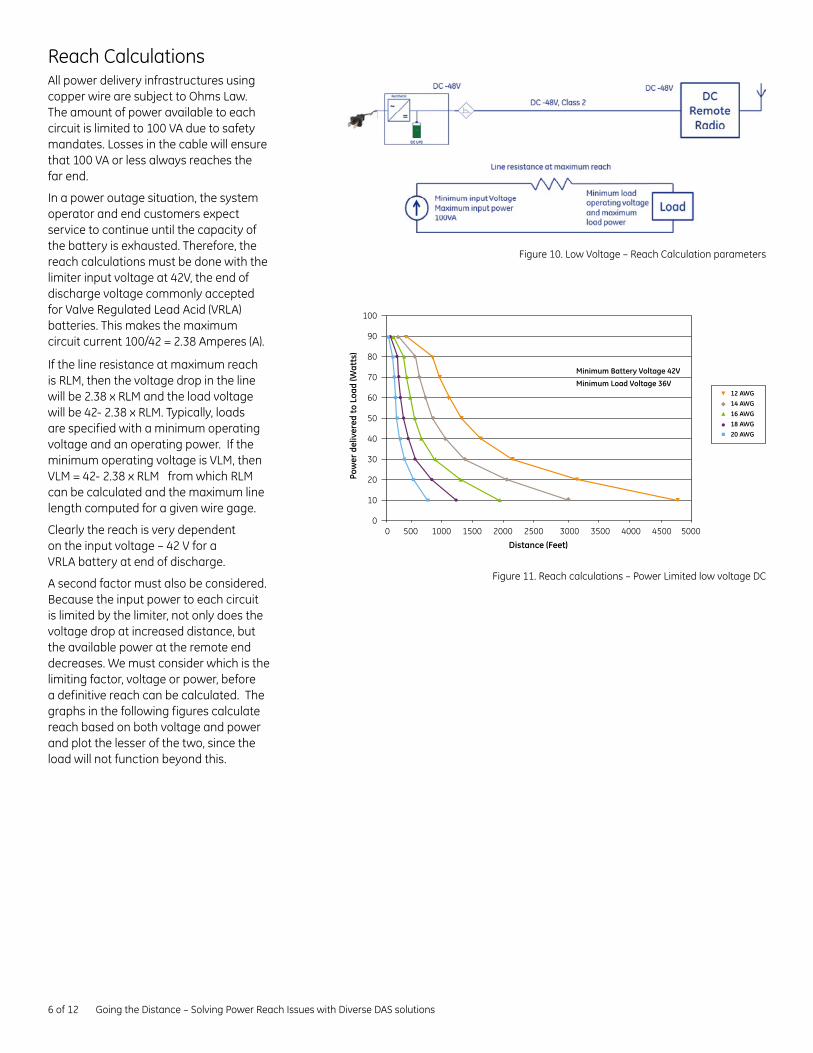
Reach CalculationsAll power delivery infrastructures using copper wire are subject to Ohms Law. The amount of power available to each circuit is limited to 100 VA due to safety mandates. Losses in the cable will ensure that 100 VA or less always reaches the far end.
In a power outage situation, the system operator and end customers expect service to continue until the capacity of the battery is exhausted. Therefore, the reach calculations must be done with the limiter input voltage at 42V, the end of discharge voltage commonly accepted for Valve Regulated Lead Acid (VRLA) batteries. This makes the maximum circuit current 100/42 = 2.38 Amperes (A).
If the line resistance at maximum reach is RLM, then the voltage drop in the line will be 2.38 x RLM and the load voltage will be 42- 2.38 x RLM. Typically, loads are specified with a minimum operating voltage and an operating power. If the minimum operating voltage is VLM, then VLM = 42- 2.38 x RLM from which RLM can be calculated and the maximum line length computed for a given wire gage.
Clearly the reach is very dependent on the input voltage – 42 V for a VRLA battery at end of discharge.
A second factor must also be considered. Because the input power to each circuit is limited by the limiter, not only does the voltage drop at increased distance, but the available power at the remote end decreases. We must consider which is the limiting factor, voltage or power, before a definitive reach can be calculated. The graphs in the following figures calculate reach based on both voltage and power and plot the lesser of the two, since the load will not function beyond this.
Figure 10. Low Voltage – Reach Calculation parameters
Figure 11. Reach calculations – Power Limited low voltage DC
100
90
80
70
60
50
40
30
20
10
00 500 1000 1500 2000 2500 3000 3500 4000 4500 5000
Distance (Feet)
Minimum Battery Voltage 42V
Minimum Load Voltage 36V
Pow
er d
eliv
ered
to L
oad
(Wat
ts)
12 AWG14 AWG16 AWG18 AWG20 AWG

7 of 12 Going the Distance – Solving Power Reach Issues with Diverse DAS solutions
If we can boost the voltage of the limiter input, so that it is a constant higher voltage even during battery discharge, the reach calculations can be performed at this higher voltage and the reach extended. This is easily done with a DC / DC converter that can operate at inputs down to 42 V and provide a constant output voltage. The output voltage is typically chosen to be 57 V, which gives a marked improvement in reach while still providing a margin of safety below the maximum SELV voltage of 60 V.
For the 12 AWG wire with a 50 W (36 V) load, the reach using 42 V battery voltage is 1,263 feet.
Using the 57 V converter boosted voltage; the reach is 4,421 feet, an increase of 250%.
To compare the reach of a 12 AWG cable with and without the voltage booster, see Figure 14.
The results plotted in Figures 12 and 13 are calculated by the GE Power Express calculator tool available from the author(s) or your local GE Critical Power sales representative.
100
90
80
70
60
50
40
30
20
10
00 500 1000 1500 2000 2500 3000 3500 4000 4500 5000
Distance (Feet)
Minimum Battery Voltage 57V
Minimum Load Voltage 36V
Pow
er d
eliv
ered
to L
oad
(Wat
ts)
12 AWG14 AWG16 AWG18 AWG20 AWG
Figure 12. Single circuit – Power Limited low voltage DC with DC Boost converter
Figure 13. Reach calculations – Power Limited low voltage DC with Boost Converter
100
90
80
70
60
50
40
30
20
10
00 500 1000 1500 2000 2500 3000 3500 4000 4500 5000
Distance (Feet)
Pow
er d
eliv
ered
to L
oad
(Wat
ts)
12 AWGwith voltage booster
12 AWG without voltage booster
Figure 14. Reach calculations – Power Limited low voltage DC with and without Boost Converter
8 of 12 Going the Distance – Solving Power Reach Issues with Diverse DAS solutions
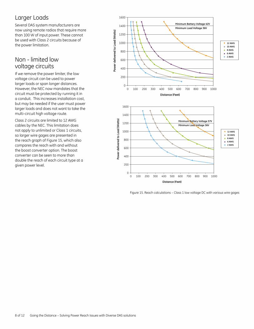
Larger LoadsSeveral DAS system manufacturers are now using remote radios that require more than 100 W of input power. These cannot be used with Class 2 circuits because of the power limitation.
Non - limited low voltage circuitsIf we remove the power limiter, the low voltage circuit can be used to power larger loads or span longer distances. However, the NEC now mandates that the circuit must be protected by running it in a conduit. This increases installation cost, but may be needed if the user must power larger loads and does not want to take the multi-circuit high voltage route.
Class 2 circuits are limited to 12 AWG cables by the NEC. This limitation does not apply to unlimited or Class 1 circuits, so larger wire gages are presented in the reach graph of Figure 15, which also compares the reach with and without the boost converter option. The boost converter can be seen to more than double the reach of each circuit type at a given power level.
0 100 200 300 400 500 600 700 800 900 1000
Distance (Feet)
Minimum Battery Voltage 42V
Minimum Load Voltage 36V
1600
1400
1200
1000
800
600
400
200
0
Pow
er d
eliv
ered
to L
oad
(Wat
ts)
12 AWG10 AWG8 AWG6 AWG2 AWG
0 100 200 300 400 500 600 700 800 900 1000
Distance (Feet)
Minimum Battery Voltage 57V
Minimum Load Voltage 36V
1600
1400
1200
1000
800
600
400
200
0
Pow
er d
eliv
ered
to L
oad
(Wat
ts)
12 AWG10 AWG8 AWG6 AWG2 AWG
Figure 15. Reach calculations – Class 1 low voltage DC with various wire gages

9 of 12 Going the Distance – Solving Power Reach Issues with Diverse DAS solutions
Tools – Reach CalculatorsBelow are screen shots of the GE Reach Calculator tools for Class 2 and Class 1 circuits for some typical loads and applications. In both illustrations, the use of the voltage booster is assumed (57 V minimum input).
These calculators are available upon request from GE Critical Power representatives.
Figure 16. Reach Calculator – Power Express Plus, Class 2 Circuits
Figure 17. Reach Calculator – Class 1 Circuits
Power Express Reach Calculator
Step 1 What is the minimum input voltage at the source? 57 Volts
41.25 Volts is recommened for traditional systems
57 Volts is recommended for systems with converter boost in the limiter
Step 2 What is the minimum input voltage required at the remote load? 38 Volts
Step 3 How many Watts are needed at 48 Volts in the remote device? 86 Watts
Step 4 What wire gauge do you use in your network for remote power? 12 Gauge
Results of Colculations
The one way distance from the 96.6W power source to the remote cabinet is: 1071 Feet VA Limit
Class 1 Circuit Reach Calculator
Case #1 Case #2
Step 1 What is the minimum input voltage at the source? 57 Volts 57 Volts
41.25 Volts is recommened for traditional systems
57 Volts is recommended for systems with converter boost in the limiter
Step 2 What is the minimum input voltage required at the remote load? 36 Volts 36 Volts
Step 3 How many Watts are needed at 48 Volts in the remote device? 1600 Watts 350 Watts
Calculated: Minimum usuable Breaker size (for power required) 60 Amp 15 Amp
Step 4 Select Wire Gauge 8 Gauge 8 Gauge
Calculated: Max Breaker size Allowed (for wire gauge selected) 45 Amp 45 Amp
Results of Colculations
The one way distance from the power source to the remote cabinet is: 120 Feet VA Limit 1,597 Feet Voltage Limit

10 of 12 Going the Distance – Solving Power Reach Issues with Diverse DAS solutions
Input Voltage range
Input Power Reach (Class 2) Reach (Class 1)
Low Power 1 38-60 V DC 86 W 1,071 ft. 12 AWG 2,455 ft. 12 AWG
Low Power 2 38-60 V DC 80 W 1,683 ft. 12 AWG 2,639 ft. 12 AWG
Med Power 1 36-75 V DC 350 W - 1,597 ft. 8 AWG
Med Power 2 36-75 V DC 500 W - 1,118 ft. 8 AWG
High Power 1 21-60 V DC 1,100 W - 508 ft. 8 AWG
High Power 2 21-60 V DC 1,600 W - 120 ft. 8 AWG
Figure 18. Typical Remote DC Power requirements
Hybrid Fiber CableWhen the power circuit does not need to be installed in a conduit, as is the case when the circuit is power limited (100 VA), this opens the door for routing the power cables in the same raceway as the fiber cable. In fact, fiber optic cables are now available with built-in power conductors. (hybrid fiber cable). This means that both power and fiber can be installed in a single operation, connecting each remote to the central communications and power location.
These cables can be used with high or low voltage, power limited power circuits and are available with differing fiber types, counts and copper wire gages as shown in the example data sheet in Figure 19.
Figure 19. Example Hybrid Fiber Cable
12 Fiber
4 Fiber
Copper sub-unit
strength member
fiber sub-unit - 900um tight buffer- aramid- PVC jacket
core wrap tape
ripcord
Integrated outer jacket
fiber sub-unit - 900um tight buffer- aramid- PVC jacket
copper sub-unit
core wrap tape
Integrated outer jacket
Copper/Fiber Composite CableRugged easy to use composite cable consiting of flexible stranded Copper conductors and integrating communications links utilizing fiber optic technologies. The breakout design privides additional protection for both the copper and fifer channels by individually protecting each with insulated jackets and all-dielectric strength members. For applications requiring remote low-voltage power and high speed communications, these designs provide an efficient single-installation option where space is of a premium and devices are not easily accessed.
Features• Rugged Riser rated constructions• Water-blocked• Flexible stranded Copper
(12 AWG, 14 AWG, 16 AWG, 18 AWG available)
• High-speed fiber optics• UL 13, UL 1666 rated• NEC 725 classified• CL2R-OF classified
Applications• Remote application of
Low-Voltage power• Security networks• IP enable appliances• Wireless Access Points
Cable Components

11 of 12 Going the Distance – Solving Power Reach Issues with Diverse DAS solutions
Cost ConsiderationsIt is important to understand all the factors that affect the cost of a DAS installation. The initial cost of equipment and installation are key parts of this, but the cost of operating and maintaining the installation are equally important.
• Materials- In a centralized power scenario we use a larger power plant and batteries in place of many small plants. In this case the larger power plant is typically more cost effective. Some of this cost advantage will be offset by the cost of power limiters if these are used to provide Class 2 protected circuits. - Materials used to connect the power to the remotes will also vary. The cost of conduit material can be eliminated by the use of Class 2 power circuits.
• Installation- Installation costs are dramatically affected by the specifics of a DAS configuration. However, one of the most significant parts of the installation cost can be power. Providing an AC drop (typically with ¾” conduit) to each remote location can be very costly when there are many remotes.
- Typical job estimates show that the cost of running power cable in conduit can be three to four times the cost of installing a Class 2 cable. With a DAS system consisting of 50 remotes, each requiring an average of 200 feet of cabling, this difference is significant.
- The remote will always require the installation of a fiber optic cable for data communications, so the use of a hybrid fiber cable will not impact the cost of installing that fiber if a Class 2 circuit protector is used. In this case, power installation is “free” because it costs no more to install the hybrid fiber cable. The cost of a hybrid fiber cable will be higher from a material standpoint, but probably no more than the combined cost of individual fiber and copper cables.
• Operation- Operational costs of each powering scenario are similar, since the power used by the remote does not vary significantly, whether it’s AC or DC.
• Maintenance- Maintenance costs are difficult to quantify; each operator and situation will require different maintenance. However, maintenance of many small battery installations will be much more difficult and costly than maintaining a single, large, centralized battery system.
Conduit Installation
50 x 200 ft . = 10,000 ft .
Est . $11 / ft . Total $110,000
Class 2 Cable installation
50 x 200 ft . = 10,000 ft .
Est . $3 / ft . Total $30,000

12 of 12 Going the Distance – Solving Power Reach Issues with Diverse DAS solutions
SummaryThere are many ways to power DAS and small cell equipment. The main driver for alternatives to a UPS for each and every remote is the sheer number of systems required – and the costs incurred in installation, operation and maintenance. When the required user experience dictates the use of UPSs, elimination of the costs associated with battery proliferation is a key consideration.
Each of the powering scenarios discussed has advantages and disadvantages, and the user must decide which is most appropriate for the particular installation. See Figure 20 for an abbreviated summary of these factors for each of the scenarios discussed.
Power Architecture
Battery Conduit Reach Max Power
RelativeCost
Advantages Disadvantages
Local Power @ remote
Many AC N/A 2,455 ft. 12 AWG
5 Simple Architecture, reserve can be specific to remote unit
High Cost, battery proliferation, ac drop for each remote
High Voltage Remote
Central1
None Long miles 2,639 ft. 12 AWG
4 Single battery location, low cost cable and installation, combine circuits for additional power
Converters at both ends of span
Low Voltage Remote – Limited Power
Central1
None Medium Kft.
1,597 ft. 8 AWG
2 Single battery location, low cost cable and installation, limiter only at source, no converters
Limited reach, cannot parallel circuits for additional remote power
Low Voltage Remote – Limited Power with voltage booster
Central1
None Long x2 Kft. 1,118 ft. 8 AWG
3 Single battery location, low cost cable and installation, limiter only at source, better reach
Needs source boost converter, cannot parallel circuits for additional remote power
Low Voltage Remote – No Power Limiter, with voltage booster
Central1
DC Medium 100’s ft.
508 ft. 8 AWG
4 Single battery location, Higher Power at remote
Larger Cables, Conduit installation cost
Figure 20. Power Scenario summary table

Imagination at work
GE Critical Power 601 Shiloh Road Plano, TX 75074 +1 800 637 1738 GECriticalPower.com
The GE brand, logo, and lumination are trademarks of the General Electric Company. © 2014 General Electric Company. Information provided is subject to change without notice. All values are design or typical values when measured under laboratory conditions.
DET-810