generation 2 man-machine interface (mmi) controllersmmi controllers – over 500,000 in operation...
TRANSCRIPT
www.grayhill.com
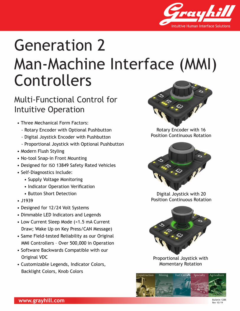
• Three Mechanical Form Factors: - Rotary Encoder with Optional Pushbutton - Digital Joystick Encoder with Pushbutton
- Proportional Joystick with Optional Pushbutton• Modern Flush Styling• No-tool Snap-in Front Mounting• Designed for ISO 13849 Safety Rated Vehicles• Self-Diagnostics Include: • Supply Voltage Monitoring • Indicator Operation Verification • Button Short Detection• J1939• Designed for 12/24 Volt Systems• Dimmable LED Indicators and Legends• Low Current Sleep Mode (<1.5 mA Current Draw; Wake Up on Key Press/CAN Message)• Same Field-tested Reliability as our Original MMI Controllers – Over 500,000 in Operation• Software Backwards Compatible with our Original VDC• Customizable Legends, Indicator Colors, Backlight Colors, Knob Colors
Generation 2Man-Machine Interface (MMI) ControllersMulti-Functional Control for Intuitive Operation
Rotary Encoder with 16 Position Continuous Rotation
Digital Joystick with 20 Position Continuous Rotation
Proportional Joystick with Momentary Rotation
Bulletin 1288 Rev 10/19

DIMENSIONS in mm [inch]
77[3.032]
113[4.449]
56,5[2.224]
38,5[1.516]
44,4[1.748]
30,0[1.181]
8,23[.324]
27[1.063]
36[1.417]
3JX0X5-G2-100XROTARY ENCODER VERSION
77[3.032]
38,5[1.516]
113[4.449]
56,5[2.224]
37,33[1.470]
8,23[.324]
27[1.063]
36[1.417]
49,9[1.965]
3JX115-G2-100XDIGITAL JOYSTICK VERSION
113[4.449]
77[3.032]
38,5[1.516]
56,5[2.224]
38,08[1.499]
8,23[.324]
27[1.063]
36[1.417]
13,59[.535]
36,59[1.441]
13°
40,89[1.610]
3JX2X5-G2-100X / 3JX305-G2-100XPROPORTIONAL JOYSTICK / DUAL PROPORTIONAL OUTPUT VERSION
LABEL
104[4.094]
(CENTERED)
68[2.677](CENTERED)
10,75 0,1.423 .003[ ]
54,2 0,12.134 .003[ ]
0 .000[ ]
2X 0.000[ ]
2,5 0,1.098 .003[ ]
54,2 0,12.134 .003[ ]
36 0,11.417 .003[ ]
36 0,11.417 .003[ ]
4X R7[.276]
4X 3[.118]
RECOMMENDED PANEL THICKNESS: 2,5 [.098] 1,0 [.039]Panel Cutout
PIN SIGNAL1 POWER2 GROUND3 CAN_H4 CAN_L
CONNECTOR: MATES WITH DEUTSCH #DT06 - 4S WITH W4S WEDGE LOCK.
Grayh i l l , Inc . • 561 H i l lg rove Avenue • LaGrange, I l l i no is 60525-5997 • USA • Phone: 708-354-1040 • Fax : 708-354-2820 • www.grayh i l l . com

-0: BLANK -1: ISO SYMBOLS -2: GENERIC TARGETS
1 3
2
4
5
6
STANDARD KEYPAD SYMBOL OPTIONS
SERIES CODE
KEYPAD SYMBOLS 0 = BLANK 1 = ISO SYMBOLS 2 = GENERIC TARGETS
INPUT TYPE 0 = ROTARY ENCODER 1 = DIGITAL JOYSTICK 2 = PROPORTIONAL JOYSTICK 3 = DUAL PROPORTIONAL OUTPUT JOYSTICK
CENTER PUSHBUTTON / OUTPUT 0 = NO CENTER PUSHBUTTON
(DUAL PROPORTIONAL OUTPUT JOYSTICK CANNOT HAVE CENTER PUSHBUTTON) 1 = CENTER PUSHBUTTON
(DIGITAL JOYSTICK ALWAYS HAS CENTER PUSHBUTTON)
GENERATION CODE G2 = GENERATION 2
INCATOR NUMBER/COLOR3A = 3 AMBER INDICATORS PER KEY
PROTOCOL C = CANbus J1939
3J X X X 5 G2 X X3A- -BACK LIGHT COLORG = GREEN W = WHITE
Contact us about optional knob colors!
STANDARD KEYPAD SYMBOL KNOBS LEGENDSLEDS
Contact us for optional LED colors
Indicator colors:• Amber (Standard)• Blue• Green• Red• White• Yellow
Backlight colors: • Green (Standard)• White (Standard)• Amber• Blue• Pure Green• Red• Yellow
Contact us for Custom Legends
Grayh i l l , Inc . • 561 H i l lg rove Avenue • LaGrange, I l l i no is 60525-5997 • USA • Phone: 708-354-1040 • Fax : 708-354-2820 • www.grayh i l l . com

Vibration, Random ISO 16750-3 4.1.2.7 Commercial vehicle, Sprung Masses
Vibration, Sinusoidal(Resonant Response between 50-80 Hz)
MIL-STD-202G, Method 204D, Test Condition C
Logarithmic Sweep from 10 Hz – 2000 Hz – 10 Hz over a period of 20 minutesDuration: 4 hours duration (12 cycles) in each of 3 orthogonal axes. Maximum displacement for 10Hz - 55Hz: 0.06”. Constant acceleration for 55Hz – 2000 Hz: 10G.
Shock/Crash Safety ISO 16750-3 4.2.2 10 pulses per direction
Drop ISO 16750-3 4.3 Height: 400 mmRepeat for all practical edges and faces
Mechanical Life Internal Testing Pro-cedure
Keypad Center Pushbutton Rotary Encoder Optical Joystick Proportional Joystick Momentary-turn Encoder
PHYSICAL SPECIFICATIONS
1M Cycles1M Cycles1M Cycles
1M Cycles1M Cycles
500K Cycles
ENVIRONMENTAL SPECIFICATIONS
Operating temperature ISO 16750-4 5.1.1.2ISO 16750-4 5.1.2.2
Low temperature -40ºC for 24hrsHigh temperature +85ºC for 96hrs
Storage Temperature ISO 16750-4 5.1.1.1ISO 16750-4 5.1.2.1
Low temperature -55ºC High temperature +105ºC
Thermal Shock (Ice Water Shock Test)
ISO 16750-4 5.4.3 High temperature +85 ºC
Altitude (Barometric Pressure)
IEC60068-2-13 Method 105C Test Condition B
Sea level to 15240m (101.3 kPa to 11.6 kPa), Exposure Time: 2 hour
Solar Radiation ISO 4892-2 Method B 1000 hours
Ingress Protection IEC 60529 / ISO 20653 8.3.3 - IP6K7
Dust – Talcum powderLiquid - 1m submersion for 30 minutes
Wash Down SAE J1211 Section 4.4>>ISO 60529 / ISO20653
375 kPa and 8.3 L/min for 10 minutes @ 15ºC
Humidity ISO 16750-4 5.7 (Damp Heat)ISO 16750-4 5.6.2.2 (Humidity Cycling)
96% Humidity at +35ºC, Duration: 240 hours
Salt Fog ISO 16750-4 5.5.1 5% aqueous solution of NaCl @ 35ºC and a pH between 6.5 and 7.2 for 48 hours
Thermal Cycling Custom Test (Extended Duration Temperature and Humidity Cycling)
Low temperature: -40°High Temperature: +85°C
Chemical Resistance ISO 16750-5 (All agents on Table 1 except Battery Fluid)
Radiated Immunity
ISO 11452-2 ALSE 80 MHz – 1000 MHz, 200V/m
ISO 11452-2 ALSE 1000 – 2500 MHz, 200V/m, 3-axis
ISO 11452-3 TEM cell 0.01 – 200 MHz, 300V/m
ISO 11452-4 Bulk current injection
0.5 MHz – 400MHz, 300mA
ISO 11452-5 150 mm Stripline
0.01 MHz – 400MHz, 300V/m
Electrostatic Discharge ISO 10605 8 powered-up test
ESD Capacitor Network 330pF, 330ΩConductive Surfaces Contact Discharge +/-15kVNon-Conductive SurfacesAir Discharge +/-25kVIndirect Discharge +/-20kV
Electrostatic Discharge ISO 10605 9 unpowered test ESD Capacitor Network 150pF / 2kΩConductive Surfaces Contact Discharge +/-15kVNon-Conductive SurfacesAir Discharge +/-25kVIndirect Discharge +/-20kV
Magnetic Field Immunity Test
ISO 11452-8:2007 15 Hz – 1000 Hz,100 A/m, Class A1 kHz – 10 kHz, 100/(F/1000)^2, Class A10 kHz – 150 kHz, 1 A/m, Class A
Radiated Emissions:Broadband/Narrowband
ISO14982
CISPR 25 (where frequency bands are specified)
CISPR 25 Class 5 where specifiedClass 3 - Average, Peak and Quasi Peak (where specified), on remaining CISPR 25 defined bands
Conducted Emissions CISPR 25 6.2 Class 5
ELECTROMAGNETIC COMPATIBILITY SPECIFICATIONS
Maximum Load ISO 16750-4 5.1 Low Temp = -40C, High Temp = +85C Duration: 4 hours at Low Temp, 11 hours at High TempMaximum load applied
Over-voltage ISO 16750-2 4.3.2 High Voltage: 36V, Duration: 60 minTmax - 20°C
Superimposed alternating voltage
ISO 16750-2 4.4 Severity 2 and 3Ri = 50mΩFrequency Range: 50Hz to 25kHzSweep Duration: 120sNumber of sweeps: 5 (continuously)
Slow decrease and increase of supply voltage
ISO 16750-2 4.5
Momentary drop in supply voltage
ISO 16750-2 4.6.1 Class B No Reset
Reset behavior at voltage drop
ISO 16750-2 4.6.2 Class C
Starting Profile IISO 16750-2 Sec. 4.6.3Formerly known as pulse 4
12V, Level II Class B and Level IV Class A24V, Level II Class A and Level III Class A
Load Dump ISO16750-2 sec 4.6.4.2.2Test AFormerly known as ISO7637-2 pulse 5
12V: Us = 101V, Ri=0.5Ω, td=400ms24V: Us = 202V, Ri=8.0Ω, td=350ms
Reverse Polarity ISO 16750-2 4.7.2.3 Voltage: -28V, Duration: 60s
Open Circuit tests ISO 16750-2 4.9.1.2 Relay and signal outputs to be connected to load
Short-circuit Protection ISO 16750-2 4.10.2 SignalCircuits
Connect all signal inputs and outputs to Vmax and GND for 60s. One circuit tested at a time.
Short-circuit Protection ISO 16750-2 4.10.3 for load circuits
ISO 8820 operating time rating +10% Minimum Class C
Parallel inductive load ISO7637-2 Pulse 1 Us = -600V
Wire Harness Induc-tance
ISO 7637-2 Pulse 2a Wire Harness Inductance
Switching Spikes ISO 7637-2 Pulse 3a Pulse 3a: Us = -300VPulse 3b: Us = +300V
Fast transients mutual coupling
ISO 7637-2 Pulse 3b Pulse a: 24V class IV Us = -80Pulse b: 24V class IV Us = +80
Slow transients mutual coupling
ISO7637-3 4.3.2 DCC Slow + = +30DCC Slow – = -30ICC slow + = +6 ICC slow - = -6
ELECTRICAL SPECIFICATIONS
www.grayhill.com Bulletin 1288 Rev 10/19