generation and transport of solid particle clusters using a … · absence of a mesh at the...
TRANSCRIPT

Abstract—A vortex ring launched into quiescent water is
used to generate and transport solid particle clusters. A vortex ring launcher, comprising a cylinder and piston, is mounted at the bottom of a water tank. One-hundred spherical, polyacetal particles (mean diameter: 1.52 mm, density: 1417 kg/m3) are placed on a mesh stretched near the cylinder outlet. The piston is used to discharge water in the cylinder vertically upward into the tank; this launches a particle-laden vortex ring. This solid-liquid two-phase flow is investigated at the Reynolds number Re, defined by the piston velocity and the cylinder diameter, of 6500, 7500, and 13000. When Re=6500, the particles are not entrained in the vortex ring, and therefore a cluster is not produced. Particles are entrained just after the launch of vortex rings at Re=7500 and 13000. These particle clusters are transported by the convection of the vortex ring. The velocity of water in the central vertical cross-section of the vortex ring decreases because of the particles, resulting in decreased circulation of the vortex ring. This reduction is more severe for lower Re.
Index Terms—Solid-liquid, two-phase flow, vortex ring, particle entrainment, Piv.
I. INTRODUCTION A vortex ring entrains matter in the vortex core with the
vortical motion, and it transports the entrained matter with the self-induced convective motion. Industrial processes that use multi-phase flow must control the transport of the dispersed phase, which may comprise gas bubbles or solid particles. Consequently, the transport of bubbles and particles by a vortex ring has been studied.
The present authors [1]-[3] have performed numerical and experimental investigations on the transport of bubbles in water. Uchiyama [1] conducted a numerical simulation of a water jet laden with small air bubbles and showed that a vortex ring, induced near the nozzle outlet by an axisymmetric disturbance, incorporates the bubbles and convects with them along the jet centerline. Uchiyama and Yoshii [2] simulated the bubble motion and behavior of a vortex ring launched toward a bubble cluster. Their simulation found that the bubbles are entrained and transported by the vortex ring and that the strength of the vortex ring is affected by the entrained bubbles. Uchiyama and Kusamichi [3] performed an experimental study to explore the interaction between a bubble cluster and a vortex ring. Small hydrogen bubbles were generated by water
Manuscript received March 16, 2017; revised July 5, 2017. T. Uchiyama is with Nagoya University, Japan (e-mail:
[email protected]). C. Yano is with Kawasaki Heavy Industries, Japan. T. Degawa is with Nagoya University, Japan.
electrolysis at the bottom of a water tank. The bubbles rose owing to their buoyant force, producing a bubble plume. A vortex ring was launched vertically upward into the bubble plume; the diameter and velocity of the vortex ring, the bubble motion, and the water velocity distribution were measured. The experiment highlighted the entrainment of bubbles in the vortex core and the resulting change in the convection of the vortex ring.
Numerical simulations have been used to study the convection of solid particles transported by a vortex ring in the air [4]. A vortex ring was launched into quiescent air, and spherical glass particles were arranged along its cross-section. The simulation was performed at the Stokes number St of 0.01; these conditions highlighted the ability of the vortex ring to entrain the particles and convectively transport them. The simulation also clarified the effects of St on the behavior of the vortex ring and particle motion. Notably, studies on particle transport in water are limited to visualization experiments in quiescent water [5], [6]. Domon et al. [5] conducted an experimental study on the transport of spherical resin particles (mean diameter: 0.4 mm, specific weight: 1.02). In their experiment, a vortex ring was loaded with particles then launched into quiescent water, and the resulting particle motion was examined by visualization. Munro et al. [6] launched a vortex ring perpendicular to particle layers on a horizontal wall to clarify the deformation and erosion of the layers caused by the collision with the vortex ring. The strength of a vortex ring affects particle transport in water, but this effect has not been fully explored. Vortex rings have the potential to form particle clusters by gathering particles dispersed in water and to transport the clusters to a specific position; this is useful for the supply and removal of particles. Therefore, techniques using vortex rings could be widely applicable to various engineering problems, such as the control of chemical reactions and heat transfer.
This study experimentally explores the generation and transport of particle clusters by vortex rings launched into quiescent water. A vortex ring launcher, comprising a cylinder and piston, is mounted at the bottom of a water tank. One-hundred spherical, polyacetal particles (mean diameter: 1.52 mm, density: 1417 kg/m3) are placed on a mesh stretched across the cross-section of the cylinder outlet. A vortex ring is launched vertically upward into the tank from the vortex ring launcher. The particle motion is visualized, and the water velocity distribution is measured by a particle image velocimetry (PIV) system. The Reynolds number Re is defined by the piston velocity and the cylinder diameter; the values of Re = 6500, 7500, and 13000 are investigated. The experiments highlight the generation and transport of the particle cluster and the behavior of the vortex ring.
Generation and Transport of Solid Particle Clusters Using a Vortex Ring Launched into Water
Tomomi Uchiyama, Chiaki Yano, and Tomohiro Degawa
253
International Journal of Chemical Engineering and Applications, Vol. 8, No. 4, August 2017
doi: 10.18178/ijcea.2017.8.4.666

II. EXPERIMENTAL
A. Experimental Set-up Fig. 1 shows a schematic of the experimental setup. The
water tank is made of transparent acrylic resin to enable flow visualization. The width and depth are both 300 mm, and the height is 600 mm. The top of the tank is open to the atmosphere. A vortex ring launcher, comprising a cylinder and piston, is mounted at the bottom of the tank. The cylinder centerline is vertical, and the cylinder outlet is positioned above the bottom of the tank. Spherical solid particles are placed on a mesh stretched near the cylinder outlet.
A vortex ring is launched vertically upward into the water tank by discharging the water in the cylinder with the piston. The piston is actuated by a slider connected to an AC servomotor. The velocity and stroke are controlled by a personal computer.
Fig. 1. Schematic diagram of the experimental setup.
B. Measurement of Water Velocity and Observation of the Vortex Ring and Particles The water velocity distribution in the central vertical
cross-section of the vortex ring (parallel to the launch axis) is measured by a particle image velocimetry (PIV) system. The image is captured by a video camera using a laser light sheet (power: 100 mW, wavelength: 532 nm, thickness: 1 mm). The spatial resolution, frame rate, and shutter speed of the camera are 640 x 480 pixel, 200 fps, and 1/200 s, respectively. Nylon particles (mean diameter: 80 µm, specific weight: 1.02) are used as the tracers.
The water velocity u in the central vertical cross-section of the vortex ring is measured on a grid of 55 × 75 points at the specific displacements of the vortex ring. The ensemble-averaged velocity u is calculated from 10 experimental measurements of u. Occasionally, a grid point fails to provide the measurement because of the presence of particles. These missed data points are excluded when calculating the ensemble-averaged velocity of each grid point. Since the number of particles is relatively small, this averaging method successfully yields a significant, smoothly distributed velocity field.
The video camera used for PIV measurements is also employed to capture images of the vortex ring and particles. The vortex ring is visualized by adding dye to the water that is launched from the cylinder.
C. Launch of Vortex Ring Fig. 2 shows the vortex ring launcher and the water tank.
The water depth is 500 mm, the piston stroke L0 is 100 mm, and the top dead center is positioned 46 mm below the cylinder outlet. The inner diameter of the cylinder, D0, is 42.5 mm, and the outer diameter is 57.8 mm. The height of the cylinder outlet from the bottom of the tank is 45 mm. The origin of the vertical (z) and horizontal (x, y) axes is placed at the center of the cylinder outlet.
Fig. 2. Vortex ring launcher and water tank.
The vortex ring is launched using the conditions listed in
Table I. The Reynolds number Re is defined as D0Um/ν, where Um is the piston velocity and ν is the kinematic viscosity of water. The experiments are performed at Re = 6500, 7500, and 13000.
TABLE I: CONDITIONS FOR LAUNCHING A VORTEX RING
Inner diameter of cylinder D0 42.5 mm Stroke of piston L0 100 mm Reynolds number D0Um/ν 6500, 7500, 13000
Fig. 3 shows the profiles for the displacement zp and
velocity U0 (= dzp/dt) of the piston, where t* is the non-dimensional time defined by tUm/D0. The velocity profile is trapezoidal, because a constant velocity Um is maintained for a specific period of time.
When fluid is discharged from a cylinder into the quiescent fluid by a piston, a laminar or turbulent vortex ring is launched depending on the discharge conditions. Glezer [7] has identified the conditions that lead to the generation of laminar and turbulent vortex rings, as shown in Fig. 4. The relevant parameters are the cylinder inner diameter D0, the piston stroke L0, and the circulation Γ0 of the vortex ring. Γ0 is computed from the following equation:
tUT
d2
0
0
20
0 ∫=Γ (1)
where T0 and U0 are the time-of-motion and velocity of the piston, respectively. The values of Γ0 for this study are plotted in Fig. 4. Although Glezer constructed Fig. 4 in the
254
International Journal of Chemical Engineering and Applications, Vol. 8, No. 4, August 2017

absence of a mesh at the cylinder outlet, the vortex rings launched in this study seem to be well within the laminar window.
Fig. 3. Displacement and velocity profiles of the piston.
Fig. 4. Experimental condition for launching a vortex ring.
D. Injection of Solid Particles Polyacetal particles with a density ρp of 1417 kg/m3 are
used in this study. The particle diameter (d) distribution is shown in Fig. 5. The mean diameter dm is 1.52 mm.
Fig. 5. Particle size distribution.
Fig. 6. Particle arrangement on the mesh at the launch of a vortex ring.
The polyacetal particles are placed on the mesh near the cylinder outlet before the vortex ring is launched. The number of particles is 100, and their total mass is 0.26 g. A photograph of the particles on the mesh is shown in Fig. 6. The mesh is stretched across the cross-section of cylinder at a height 30 mm below the cylinder outlet. The mesh has a wire diameter and aperture of 200 µm and 435 µm, respectively. The characteristics of the mesh and particles are listed in Table II.
TABLE II: CHARACTERISTICS OF THE MESH AND SOLID PARTICLES
Mesh wire diameter 0.2 mm Mesh aperture 0.435 mm Mean particle diameter dm 1.52 mm Particle density ρp 1417 kg/m3 Number of particles on mesh np0 100
Crowe et al. [8] hypothesized that particle motion could be
classified by the responsiveness of particle to large-scale eddies; they proposed that the Stokes number St is the appropriate parameter for estimating particle motion. St is the ratio of the particle response time τp to the characteristic time τl of the fluid flow, τp/ τl, where τp is given by the following equation:
( )νρρτ lmpp d 18/2= (2)
and ρl is the density of water. Assuming that τl = D02/Γ0, the
values of the Reynolds number Re used in this study, Re = 6500, 7500, and 13000, correspond to the St values of 0.82, 0.94, and 1.55, respectively.
III. RESULTS AND DISCUSSION
A. Behavior of Vortex Ring Launched without Solid Particles First, a vortex ring is launched without particles, and its
characteristics are examined for this particular experimental setup. An image of the central vertical cross-section of the vortex ring is shown in Fig. 7, where Re = 13000. The fluid is visualized by adding dye to the water launched from the cylinder. A vortex pattern is clearly observed. A shear layer forms at the boundary between the water discharged from the cylinder and the quiescent water in the tank, and the dye is entrained in the vortex core as the shear layer rolls up. A laminar distribution of dye forms behind the vortex ring, and there is no active mixing. Similar features are observed when Re = 6500 and 7500. These images confirm that laminar vortex rings are launched from this experimental setup, in agreement with Glezer's flow map [7] (Fig. 4). The z-coordinate at the center of the vortex core is regarded as the displacement of the vortex ring zv, as indicated in Fig. 7.
The displacement of the vortex ring, zv, changes with time as shown in Fig. 8. The time when the piston reaches the top dead center is defined as t* = 0. The change in zv is almost linear, indicating that the vortex ring rises with a constant velocity inf quiescent water. The displacement of the vortex ring, which is measured without the mesh, is presented by broken lines in Fig. 8. The mesh hardly affects the displacement. The displacement is closely related to the
255
International Journal of Chemical Engineering and Applications, Vol. 8, No. 4, August 2017

velocity distribution within the vortex ring, so the mesh is not expected to significantly affect the velocity distribution.
Fig. 7. Image of a vortex ring launched without particles at Re = 13000.
Fig. 8. Time variation of the displacement of a vortex ring launched without
particles. The velocity distribution of water in the central vertical
cross-section of the vortex ring is shown in Fig. 9. The ensemble-averaged velocity u is shown at displacements of zv/D0 = 2, 4, and 6. Vortical flow is observed around the vortex core as well as vertically upward flow around the central axis. The velocity distribution is almost axisymmetric. When the vortex ring convects, neither deformation nor breakup occurs. It should be noted that the velocity at Re = 13000 decreases slightly with convection. This occurs because the launch velocity of the vortex ring is high; therefore, the friction between the vortex ring and the surrounding quiescent water causes a large amount of energy dissipation.
The distribution of vorticity ω (= u×∇ ) is shown in Fig. 10, where the vorticity is calculated from the ensemble-averaged velocity presented in Fig. 9. The absolute value of vorticity is locally high at the vortex core and decreases as the vortex ring convects. The diameter of the vortex ring remains almost constant.
The circulation Γ is estimated from the distribution of the vorticity ω within a square region of 1.25D0 x 1.25 D0 around the vortex core. Fig. 11 shows the relationship between Γ and the displacement of the vortex ring. Γ decreases slightly with the convection of the vortex ring
when Re = 6500 and 7500. When Re = 13000, the decrease in Γ is remarkable for displacements zv/D0 ≤ 4. This is attributable to energy dissipation by the surrounding quiescent water.
Fig. 9. Velocity distribution of water around the particle-free vortex ring.
Fig. 10. Vorticity distribution of water around the particle-free vortex ring.
Fig. 11. Axial change in the circulation of the particle-free vortex ring.
B. Particle Motion Relative to the Vortex Ring Fig. 12 shows the particles and vortex ring for Re = 6500.
The images are captured at six values of zv. The laser light is not used. The vortex ring is produced at zv/D0 = 1; the roll-up of the shear layer originates from the cylinder tip. This corresponds to the time (t* = 1.17) when the piston nearly reaches the top dead center. The particles are also injected vertically upward from the cylinder, and most of the particles
256
International Journal of Chemical Engineering and Applications, Vol. 8, No. 4, August 2017

distribute uniformly around the central axis of the vortex ring (x/D0 = 0). Some particles are entrained in the vortex core of the vortex ring. There are no particles around a fully developed vortex ring (zv/D0 = 2) because the strength of the vortex ring is low; the particles are not held inside the vortex core and fall vertically downward. At zv/D0 ≥ 3, the vortex ring convects vertically upward without any particles.
Fig. 13 shows the vortex ring with the particles at Re = 7500. When zv/D0 = 1, a number of particles are entrained in the vortex core, generating a particle cluster. When zv/D0 = 2 and 3, some particles drop out from the vortex core and fall around the central axis of the vortex ring. The number of particles inside the vortex core lessens as the vortex ring convects, as discussed later. When zv/D0 ≥ 4, the particle cluster is transported vertically upward with the vortex ring.
Fig. 12. Images of the particles and vortex ring at Re = 6500.
Fig. 13. Images of the particles and vortex ring at Re = 7500.
When Re = 13000, the particles and the vortex ring behave
as shown in Fig. 14. At zv/D0 = 1, the vortex ring entrains many particles, producing a particle cluster. Some particles distribute concentrically around the vortex core; the swirling motion is because of the vortical motion of water. There are still many particles around the vortex core at zv/D0 ≥ 2, but some particles drop out near the central axis of the vortex ring because the strength of the vortex ring decreases. The
fraction of particles that drop out is relatively small. The vortex ring at Re = 13000 is more effective at transporting solid particles.
Fig. 14. Images of the particles and vortex ring at Re = 13000.
Fig. 15. Images of horizontal cross-sections at zv/D0 = 2 and 4.
Fig. 15 shows the images of the particles for zv/D0 = 2 and
4. The camera is placed at the centerline of the cylinder above the water tank, and the images are acquired by focusing the camera on the planes corresponding to zv/D0 = 2 and 4. In the images, the outer edge of the vortex ring is indicated by a solid line, and the center of the vortex core is shown with a broken line. When Re = 6500, the particles distribute around the central axis at zv/D0 = 2. The particles injected from the cylinder into the tank are dropping, as shown in Fig. 12, and such particles are photographed. When Re = 7500, some particles concentrate around the vortex core at zv/D0 = 2, and many particles distribute around the central axis. They are dropping out from the vortex core, as shown in Fig. 13. At zv/D0 = 4, the number of particles around the central axis reduces, but the particle distribution near the vortex core is the same as that at zv/D0 = 2. In the case of Re = 13000, a number of particles distribute around the central axis and vortex core at zv/D0 = 2. The concentration of particles around
257
International Journal of Chemical Engineering and Applications, Vol. 8, No. 4, August 2017

the central axis decreases at zv/D0 = 4. The vortex ring is highly effective at transporting particles, as demonstrated in Fig. 14.
Fig. 16 shows the images of the particles and vortex ring just after their injection, where the images at lower displacements of the vortex ring (0.2 ≤ zv/D0 ≤ 0.8) are presented. When Re = 6500, the particles are injected almost uniformly from the cylinder at zv/D0 ≥ 0.4 and are hardly entrained in the shear layer of water. When Re = 7500, the particles distribute almost flatly at zv/D0 = 0.4; maintaining the same configuration as before the water is discharged from the cylinder. The particles are injected with maintaining their configurations at the initial time. At zv/D0 ≥ 0.6, the distribution of particles becomes convex because particles fall around the central axis. When Re = 13000, the particles are entrained in the shear layers that roll up to form the vortex ring, and some particles swirl around the vortex core. The particles are still inside the cylinder at zv/D0 = 0.2 when Re = 6500 and 7500, but they are injected from the cylinder when Re = 13000. This demonstrates that the particles are successfully accelerated by the vortex ring.
Fig. 16. Images of the particles and vortex ring just after their launch from the
cylinder. Particle motion is related to the behavior of large-scale
eddies through the Stokes number St [8]. Studies of particle motion in a wake [9], in mixing layers [10], [11], and around a vortex pair [12] show that for St ≈ 1, particles accumulate in thin layers, outlining the boundaries of a large-scale eddy. Since Re = 13000 corresponds to St = 1.55 in the present experiment, the particles around the vortex core (Figs. 14, 15, and 16) are expected to preferentially distribute in this manner.
The number of particles np in a rectangular region (2.5D0 x 1.25D0) surrounding the vortex core is measured to quantify the effect of vortex ring convection on the number of particles inside the vortex core. Fig. 17 shows the relationship between np and the displacement of the vortex ring zv, where np0 (= 100) denotes the number of particles placed on the mesh at the initial time (t* = 0). When Re = 6500, 65% of the particles distribute around the vortex core just after the launch of the vortex ring (zv/D0 = 1), but there
are no particles at zv/D0 ≥ 2. When Re = 7500, 95% of the particles concentrate around the vortex core at zv/D0 = 1. Although np decreases with the convection of the vortex ring, it remains unchanged at zv/D0 ≥ 4. When Re = 13000, 95% of the particles are entrained in the vortex core at zv/D0 = 1. np reduces with increasing zv, but the reduction is relatively smaller. This figure demonstrates that the vortex ring is capable of transporting the particles.
Fig. 17. Axial change in the number of particles inside the vortex ring.
C. Effect of Particles on the Behavior of the Vortex Ring The displacement profile of the vortex ring is shown in Fig.
18. In the case of Re = 6500, the profile is linear, indicating that the vortex ring convects with a constant velocity. The gradient of the line (convection velocity) is smaller than when the vortex ring is launched without particles, because the strength of the vortex ring is reduced by the particles, as explained later. When Re = 7500 and 13000, the profiles are also linear (constant convection velocity), even though the vortex ring transports more particles. The reduction in velocity because of particles becomes more significant as Re decreases. This trend occurs because the energy required to inject the particles and the energy dissipation caused by the velocity difference between the particles and the water are larger than the kinematic energy of the vortex ring.
The distribution of the ensemble-averaged velocity u in the central vertical cross-section of the vortex ring is shown in Fig. 19. At every value of Re, the velocity is lower than that in the distributions measured without particles (Fig. 9). Particles with more inertia than the surrounding water are launched; therefore, the energy delivered to water from the piston is less when particles are present. The drag force induced by the velocity difference between the particles and the water also contributes to the observed trend. The velocity reduction increases in magnitude as the displacement of the vortex ring increases.
Fig. 18. Displacement profile of the vortex ring.
258
International Journal of Chemical Engineering and Applications, Vol. 8, No. 4, August 2017
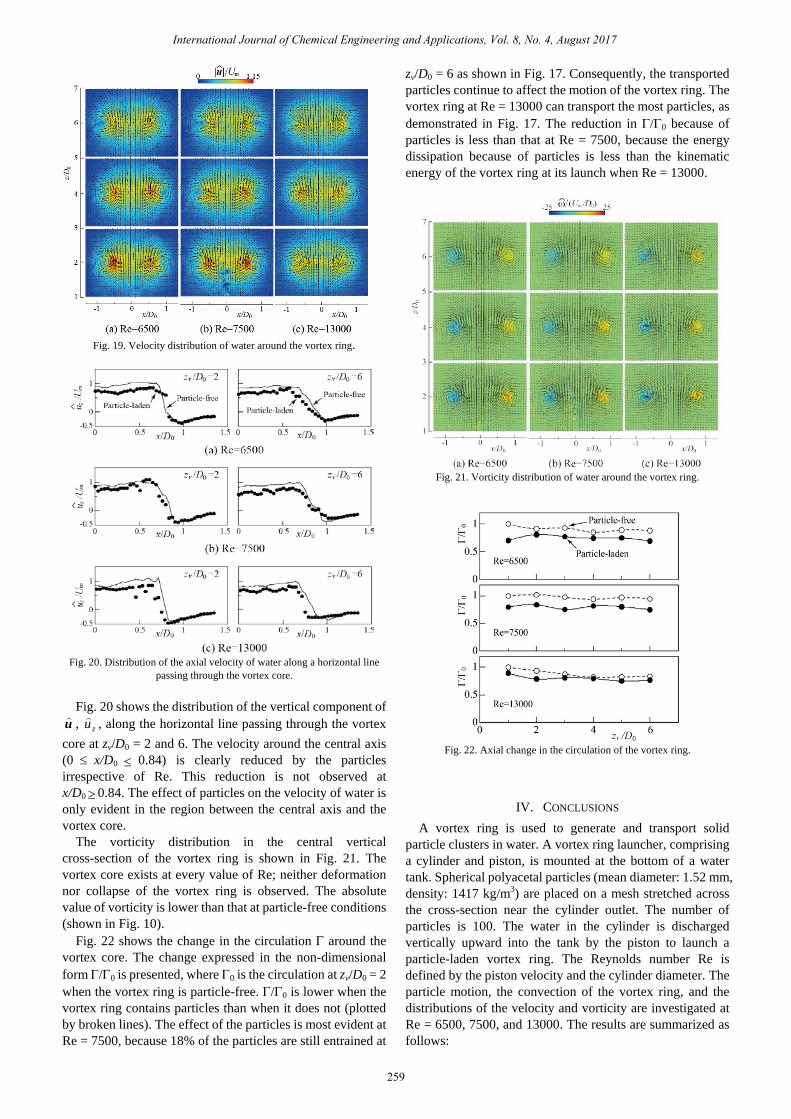
Fig. 19. Velocity distribution of water around the vortex ring.
Fig. 20. Distribution of the axial velocity of water along a horizontal line
passing through the vortex core. Fig. 20 shows the distribution of the vertical component of
u , zu , along the horizontal line passing through the vortex core at zv/D0 = 2 and 6. The velocity around the central axis (0 ≤ x/D0 ≤ 0.84) is clearly reduced by the particles irrespective of Re. This reduction is not observed at x/D0 ≥ 0.84. The effect of particles on the velocity of water is only evident in the region between the central axis and the vortex core.
The vorticity distribution in the central vertical cross-section of the vortex ring is shown in Fig. 21. The vortex core exists at every value of Re; neither deformation nor collapse of the vortex ring is observed. The absolute value of vorticity is lower than that at particle-free conditions (shown in Fig. 10).
Fig. 22 shows the change in the circulation Γ around the vortex core. The change expressed in the non-dimensional form Γ/Γ0 is presented, where Γ0 is the circulation at zv/D0 = 2 when the vortex ring is particle-free. Γ/Γ0 is lower when the vortex ring contains particles than when it does not (plotted by broken lines). The effect of the particles is most evident at Re = 7500, because 18% of the particles are still entrained at
zv/D0 = 6 as shown in Fig. 17. Consequently, the transported particles continue to affect the motion of the vortex ring. The vortex ring at Re = 13000 can transport the most particles, as demonstrated in Fig. 17. The reduction in Γ/Γ0 because of particles is less than that at Re = 7500, because the energy dissipation because of particles is less than the kinematic energy of the vortex ring at its launch when Re = 13000.
Fig. 21. Vorticity distribution of water around the vortex ring.
Fig. 22. Axial change in the circulation of the vortex ring.
IV. CONCLUSIONS A vortex ring is used to generate and transport solid
particle clusters in water. A vortex ring launcher, comprising a cylinder and piston, is mounted at the bottom of a water tank. Spherical polyacetal particles (mean diameter: 1.52 mm, density: 1417 kg/m3) are placed on a mesh stretched across the cross-section near the cylinder outlet. The number of particles is 100. The water in the cylinder is discharged vertically upward into the tank by the piston to launch a particle-laden vortex ring. The Reynolds number Re is defined by the piston velocity and the cylinder diameter. The particle motion, the convection of the vortex ring, and the distributions of the velocity and vorticity are investigated at Re = 6500, 7500, and 13000. The results are summarized as follows:
259
International Journal of Chemical Engineering and Applications, Vol. 8, No. 4, August 2017

(1) When Re = 6500, the particles are injected into the tank, but the vortex ring does not entrain particles at a displacement of zv/D0 ≥ 2. A particle cluster is not generated. When Re = 7500, the vortex ring generates the particle cluster just after its launch. Some particles drop out from the cluster with the convection of the vortex ring at 2 ≤ zv/D0 ≤ 4, but the vortex ring successfully transports the remaining particle cluster in the direction of its convection at zv/D0 ≥ 4. When Re = 13000, the vortex ring entrains many particles and transports them in direction of its convection.
(2) When Re = 7500 and 13000, the vortex ring can entrain 95% of the particles placed on the mesh and successfully produce a particle cluster.
(3) A vortex ring laden with particles convects at a constant velocity that is slightly less than the velocity of a particle-free vortex ring. The velocity decreases because of the particles; this effect becomes larger with decreasing Re.
(4) The velocity in the central vertical cross-section of the vortex ring reduces because of the particles. The reduction becomes more significant as the displacement of the vortex ring increases. A remarkable reduction in velocity occurs at Re = 6500. Notably, the vortex core exists, and the vortex ring neither deforms nor collapses.
(5) Circulation around the vortex core reduces because of the particles. Although the vortex ring is more effective at transporting particles when Re = 13000, the reduction in circulation is smaller. This occurs because the energy dissipation because of particles is less than the kinematic energy of the vortex ring at its launch.
REFERENCES [1] T. Uchiyama, “Three-dimensional vortex simulation of bubble
dispersion in excited round jet,” Chem. Eng. Sci., vol. 59, pp. 1403-1413, 2004.
[2] T. Uchiyama and Y. Yoshii, “Numerical study of the entrainment and transport of gas bubbles by a vortex ring,” J. Chem. Eng. Process Tech., vol. 6, 2015.
[3] T. Uchiyama and S. Kusamichi, “Interaction of bubbles with vortex ring launched into bubble plume,” Advances in Chemical Engineering and Science, vol. 3, pp. 207-217, 2013.
[4] H. Yagami and T. Uchiyama, “Numerical simulation for the transport of solid particles with a vortex ring,” Advanced Powder Technology, vol. 22, pp. 115-123, 2011.
[5] K. Domon et al., “Mass transport by a vortex ring,” J. Phys. Soc., Japan, vol. 69, pp. 120-123, 2000.
[6] R. J. Munro et al., “Sediment resuspension and erosion by vortex rings,” Phys. Fluids, vol. 21, pp. 046-601, 2009.
[7] A. Glezer, “The formation of vortex rings,” Phys. Fluids, vol. 31, pp. 3532-3542, 1988.
[8] C. T. Crowe et al. “Particle dispersion by coherent structures in free shear flows,” Particle Science Technology J., vol. 3, pp. 149-158, 1985.
[9] L. Tang et al., “Self-organizing particle dispersion mechanism in a plane wake,” Phys. Fluids A., vol. 4, pp. 2244-2251, 1992.
[10] F. Wen et al., “Particle dispersion by vortex structures in plane mixing layers,” Trans. ASME, J. Fluid Eng., vol. 114, pp. 657-666, 1992.
[11] X. Yang et al., “Modelling of heavy and buoyant particle dispersion in a two-dimensional turbulent mixing layer,” Powder Technology, vol. 178, pp. 151-165, 2007.
[12] Uchiyama and Shimada, “Numerical simulation of the interactions between a vortex pair and solid particles near a wall,” Powder Technology, vol. 257, pp. 55-67, 2014.
Tomomi Uchiyama was born in Shizuoka Prefecture, Japan in 1962. He finished the Graduate School of Engineering, Nagoya University, Japan in 1987, and received his degree, Dr. Eng., from Nagoya University in 1992. He is a professor at Institute of Materials and Systems for Sustainability, Nagoya University, Japan. His current research interests lie in fluid engineering, especially CFD, multi-phase flow, and micro-hydraulic turbine.
260
International Journal of Chemical Engineering and Applications, Vol. 8, No. 4, August 2017