generation track overview lecture - event …€¢ limit mechanical stress for external ground...
TRANSCRIPT

2/20/2017
1
34th Hands-On Relay School
Generation Track
Overview Lecture
Generator Design, Connections, and Grounding

2/20/2017
2
Generator Main Components
• Stator
– Core lamination
– Winding
• Rotor
– Shaft
– Poles
– Slip rings
Stator Core
Source: www.alstom.com/power/fossil/gas/

2/20/2017
3
Stator (Core + Winding)
Core Lamination
Winding (Roebel bars)
Winding Connections
Typical Types of Generator Windings Stator Winding: Random-Wound Coils

2/20/2017
4
Typical Types of Generator Windings Stator Winding: Form-Wound Coils
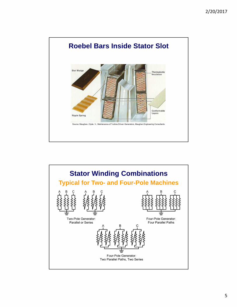
Typical Types of Generator Windings Stator Winding: Roebel Bars
2/20/2017
5
Roebel Bars Inside Stator Slot
Source: Maughan, Clyde. V., Maintenance of Turbine Driven Generators, Maughan Engineering Consultants
Stator Winding CombinationsTypical for Two- and Four-Pole Machines

2/20/2017
6
Series Connection of Roebel Bars
Source:www.ansaldoenergia.com/Hydro_Gallery.asp
Series connection
Rotor

2/20/2017
7
Classification of Synchronous Generators
Synchronous Generator Classification
Rotor designCylindrical rotor
Salient-pole rotor
Cooling: Stator and rotor
Direct
Indirect
Field winding connection to dc
source
Brush
Brushless
Rotor Design
Salient-Pole Rotor
Cylindrical Rotor

2/20/2017
8
Two-Pole Round Rotor
Source: www.alstom.com
Salient Pole Rotor
Source:www.ansaldoenergia.com/Hydro_Gallery.asp

2/20/2017
9
Stator Winding Cooling
Directly CooledIndirectly Cooled
Cooling Ducts, Water Cooled Bar
Rotor Winding Cooling
Directly CooledIndirectly Cooled

2/20/2017
10
Field Winding Connection to DC Source
Brush Type
Field Winding Connection to DC Source
Brushless
2/20/2017
11
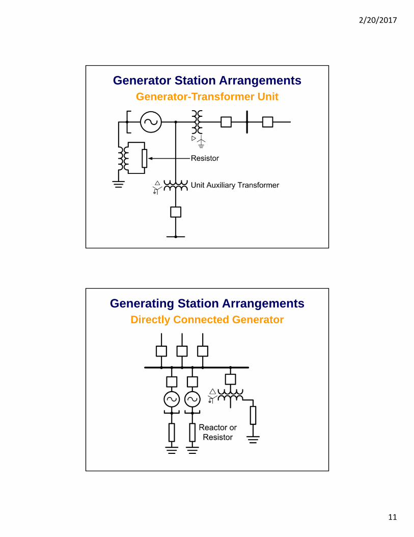
Generator Station ArrangementsGenerator-Transformer Unit
Generating Station ArrangementsDirectly Connected Generator
2/20/2017
12
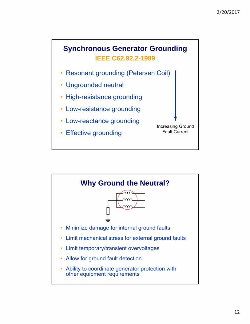
• Resonant grounding (Petersen Coil)
• Ungrounded neutral
• High-resistance grounding
• Low-resistance grounding
• Low-reactance grounding
• Effective grounding
IEEE C62.92.2-1989
Synchronous Generator Grounding
Increasing GroundFault Current
Why Ground the Neutral?
• Minimize damage for internal ground faults
• Limit mechanical stress for external ground faults
• Limit temporary/transient overvoltages
• Allow for ground fault detection
• Ability to coordinate generator protection with other equipment requirements

2/20/2017
13
Ungrounded Neutral
• No intentional connection to ground
• Maximum ground fault current higher than for resonant grounding
• Excessive transient overvoltages may result
High-Resistance Grounding
• Low value resistor connected to secondary of distribution transformer
• Resistor value selected to limit transient overvoltages
• Maximum single-phase-to-ground fault current: 5–15 A
2/20/2017
14
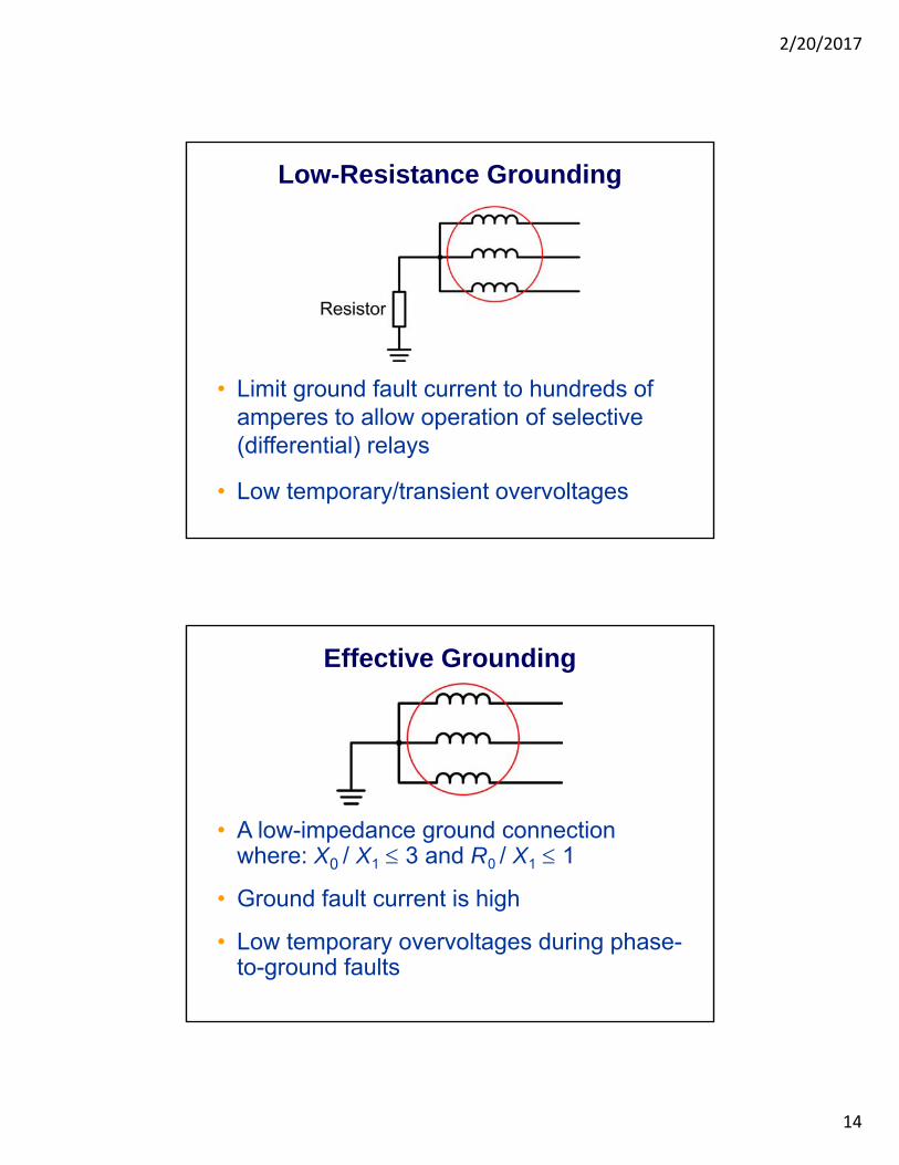
Low-Resistance Grounding
• Limit ground fault current to hundreds of amperes to allow operation of selective (differential) relays
• Low temporary/transient overvoltages
Effective Grounding
• A low-impedance ground connection where: X0 / X1 3 and R0 / X1 1
• Ground fault current is high
• Low temporary overvoltages during phase-to-ground faults

2/20/2017
15
Generator Capability Curves
Defining Generator Capability
• Curve provided by the generator manufacturer
• Defines the generator operating limits during steady state conditions
• Assumes generator is connected to an infinite bus
• Limits are influenced by:
– Terminal voltage
– Coolant
– Generator construction

2/20/2017
16
Generator Capability Curve for a Round Rotor Generator
Generator Capability Curve for a Salient Pole Generator
2/20/2017
17
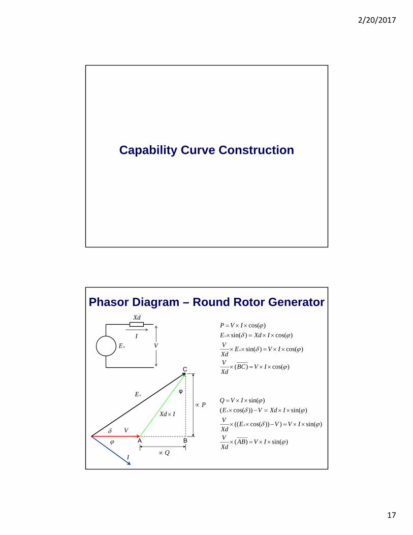
Capability Curve Construction
Phasor Diagram – Round Rotor Generator
)cos()(
)cos()sin(
)cos()sin(
)cos(
0
0
IVBCXd
V
IVEXd
V
IXdE
IVP
)sin()(
)sin()))cos(((
)sin())cos((
)sin(
0
0
IVABXd
V
IVVEXd
V
IXdVE
IVQ
0E
Xd
I
V
φ
A B
C
0E
V
IXd
Q
P
I

2/20/2017
18
Power Angle Characteristic
P
Operation with Constant Active Power and Variable Excitation
A B
C
0E
V
IXd
Q
I
I
I 0 E 0 E
IXd IXd
B’B’’
C’C’’
P
Q
Q
4513.1
606.1
87.361
00.1
6.1
I
I
I
V
Xd
5.7831.1
7.21466.3
15.3334.2
0
0
0
E
E
E

2/20/2017
19
Power Angle Characteristic
5.7831.1
7.21466.3
15.3334.2
0
0
0
E
E
E
P
V-Curves
(p.u.) 0E
).( upI
Current Excitation
inductive cos cap. cos

2/20/2017
20
Operation with Constant Apparent Power and Variable Excitation
A B
C
0E
V
IXd
I
87.361
00.1
6.1
I
V
Xd
Operation with Constant Excitation and Variable Active Power
A B
C
0E
V
IXd
I
0 E
IXd
I The
or. S
tabi
lity
Lim
it

2/20/2017
21
Capability Curve – Round Rotor
max.
0 P
0
)cos()sin(
0
0
E
IVEXd
V
Xd
E
IVVEXd
V
VV - Q
0
)sin()))cos(((
0
0
625.0VV -
Q
Xd
The
or. S
tabi
lity
Lim
it
0.1
6.1
V
Xd
P (
Rea
l Pow
er)
Q (Reactive Power)
Generator Fault Protection

2/20/2017
22
Generator Fault Protection
• Stator phase faults
• Stator ground faults
• Field ground faults
• External faults (backup protection)
Stator Phase Fault Protection
• Phase fault protection
– Percentage differential
– High-impedance differential
– Self-balancing differential
• Turn-to-turn fault protection
– Split-phase differential
– Split-phase self-balancing

2/20/2017
23
Phase Fault ProtectionPercentage Differential
Dual-Slope Characteristic

2/20/2017
24
O O O
Phase Fault ProtectionHigh-Impedance Differential
Phase Fault ProtectionSelf-Balancing Differential
http://www.polycastinternational.com/old_cat/pdfs/Section4/Section4-Part2.pdf

2/20/2017
25
Stator Winding Coils with Multiple Turns
Turn-to-Turn Fault ProtectionSplit-Phase Self-Balancing

2/20/2017
26
Turn-to-Turn Fault ProtectionSplit-Phase Percentage Differential
Stator Ground Fault Protection
• High-impedance-grounded generators
– Neutral fundamental-frequency overvoltage
– Third-harmonic undervoltage or differential
– Low-frequency injection
• Low-impedance-grounded generators
– Ground overcurrent
– Ground directional overcurrent
– Restricted earth fault (REF) protection

2/20/2017
27
Ground Fault in a Unit-Connected Generator
G
T XG1
XG2
3R
XG0
XC0
XC2
XC1
XT1
XT2
XT0
XS0
XS2
XS1
S
High-Impedance Grounded GeneratorNeutral Fundamental Overvoltage
Fault Location/ % of Winding
Voltage V
F1 / 3%
F2 / 85%
3% •3
Vnom
85% •3
Vnom
2/20/2017
28
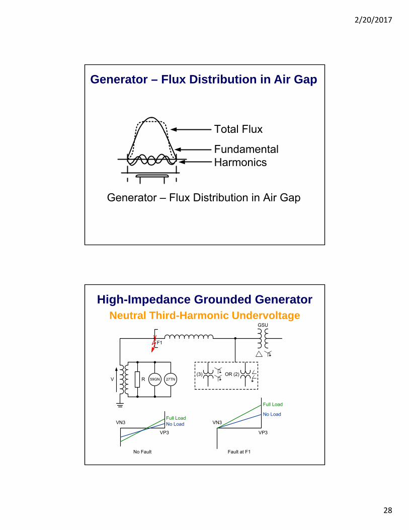
Generator – Flux Distribution in Air Gap
Total Flux
FundamentalHarmonics
Generator – Flux Distribution in Air Gap
Neutral Third-Harmonic Undervoltage
59GNRV
F1
GSU
Full LoadNo LoadVN3
No Fault
VP3
Full Load
No Load
VP3
VN3
Fault at F1
(3) OR (2)27TN
High-Impedance Grounded Generator

2/20/2017
29
Third-Harmonic Differential
59GNRV
GSU
(3)(3)
–+
Pickup Setting
• 3 3k VP VN
VN3 VP3 59THD
Third-Harmonic Differential Element
High-Impedance Grounded Generator
Generator Winding Analysis
• Generator data
– 18 poles
– 216 slots
• Winding pitch
– Full pitch = 216/18 = 12 slots
– Actual pitch = 128 – 120 = 8 slots
– Actual pitch / full pitch = 8/12 = 2/3

2/20/2017
30
Full-Pitch Winding
2/3 Pitch WindingRemoves Third Harmonic

2/20/2017
31
Low-Frequency Injection
59GNR
GSU
(3) OR (2)
V
I
64S
Coupling Filter
Low-Frequency Voltage Injector
Protection Measurements
High-Impedance Grounded Generator
100% Stator Ground Fault ProtectionElements Coverage

2/20/2017
32
Low-Impedance-Grounded GeneratorGround Overcurrent and Directional Overcurrent
Low-Impedance-Grounded GeneratorGround Differential

2/20/2017
33
Low-Impedance-Grounded GeneratorSelf-Balancing Ground Differential
Zero-Sequence CTs
http
://w
ww
05.a
bb.c
om/g
loba
l/sco
t/sc
ot23
5.ns
f/ve
rityd
ispl
ay/b
eaae
b012
3376
5418
3257
3460
062a
765/
$file
/1va
p42
8561
-db_
byz.
Zero-sequence CT
2/20/2017
34
Field Ground Protection
Field Ground Protection
• Types of rotors
• Winding failure mechanisms
• Importance of field ground protection
• Field ground detection methods
• Switched-DC injection principle of operation
• Shaft grounding brushes

2/20/2017
35
Salient Pole Rotor
Source:www.ansaldoenergia.com/Hydro_Gallery.asp
A Round Rotor Being Milled
Source: Maughan, Clyde. V., Maintenance of Turbine Driven Generators, Maughan Engineering Consultants

2/20/2017
36
Round Rotor – End Turns
Source: Main Generator Rotor Maintenance – Lessons Learned - EPRI
Source: Main Generator Rotor Maintenance – Lessons Learned - EPRI
Two-Pole Round Rotor
Source: www.alstom.com

2/20/2017
37
Two-Pole Round Rotor
Source: www.alstom.com
Two-Pole Round Rotor
Source: www.alstom.com

2/20/2017
38
Round Rotor Slot — Cross Section
Slot Armor
Copper Winding
Creepage Block
Coil SlotWedge
Turn InsulationEnd Windings
Retaining RingRetaining Ring Insulation
Winding Short
Winding GroundWinding Ground
Field Winding Failure Mechanisms in Round Rotors
• Thermal deterioration
• Thermal cycling
• Abrasion
• Pollution
• Repetitive voltage surges

2/20/2017
39
Salient Pole Cross Section
Turn Insulation
Winding Turn
Pole Body
Pole BodyInsulation
Pole Collar
Pole Collar
* Strip-On-Edge
Winding Ground
Winding Short
Field Winding Failure Mechanisms inSalient Pole Rotors
• Thermal deterioration
• Abrasive particles
• Pollution
• Repetitive voltage surges
• Centrifugal forces
2/20/2017
40
Importance of Field Ground Detection
• Presence of a single point-to-ground in field winding circuit does not affect the operation of the generator
• Second point-to-ground can cause severe damage to machine
– Excessive vibration
– Rotor steel and / or copper melting
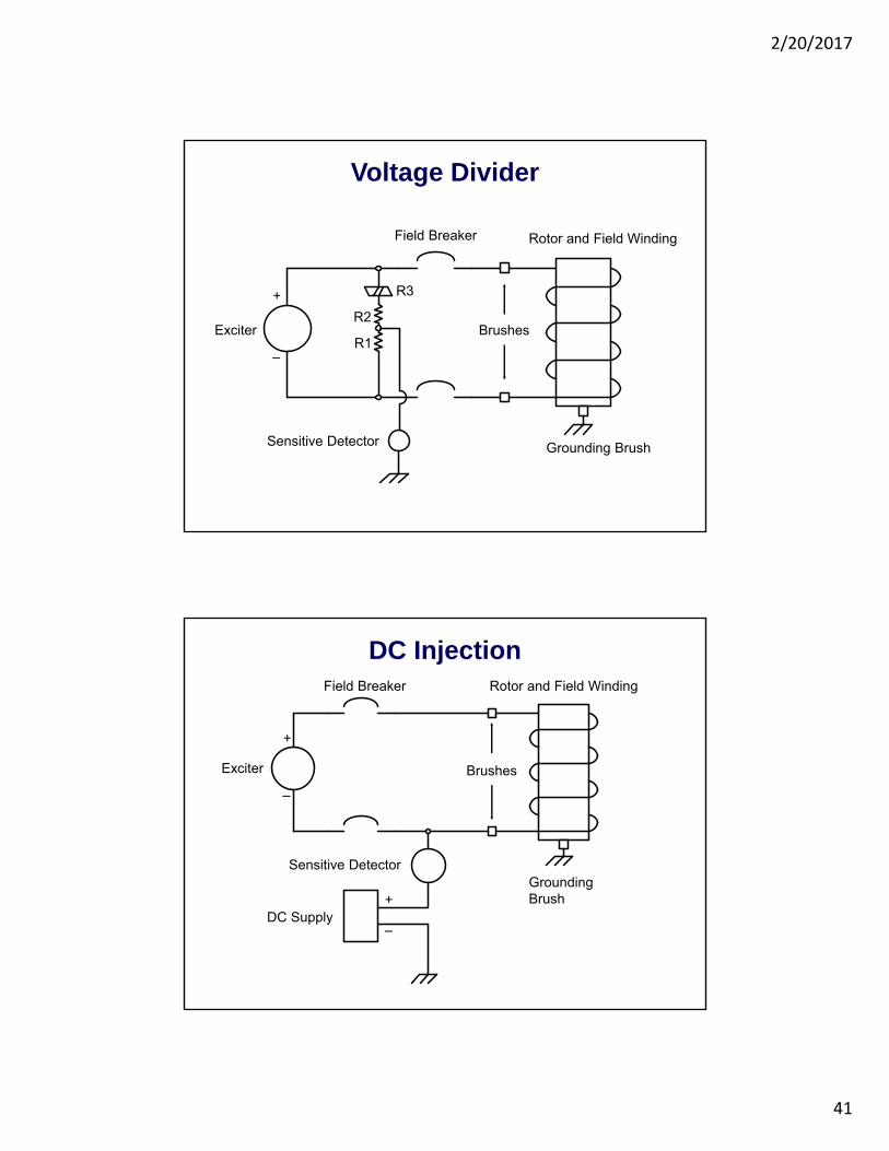
Rotor Ground Detection Methods
• Voltage divider
• DC injection
• AC injection
• Switched-DC injection
2/20/2017
41
Voltage Divider
+
–
Exciter
Field Breaker
Grounding Brush
Rotor and Field Winding
Brushes
Sensitive Detector
R1
R2
R3
DC Injection
+
–
Exciter
Field Breaker
GroundingBrush
Rotor and Field Winding
Brushes
Sensitive Detector
DC Supply+
–

2/20/2017
42
AC Injection
+
–
Exciter
Field Breaker
GroundingBrush
Rotor and Field Winding
Brushes
Sensitive Detector
AC Supply
Switched-DC Injection Method
+
–
Exciter
Field Breaker
GroundingBrush
Rotor and Field Winding
Measured Voltage
R1
R2
Rs
Brushes

2/20/2017
43
Switched DC Injection Principle of Operation
Measured Voltage (Vrs)
R
R
Rs
Cfg
Rx
+
–
VDC
V
Vrs
Vrs
Voscp
Voscn
Vosc
Shaft Grounding with Carbon Brush

2/20/2017
44
Shaft Grounding with Wire Bristle Brush
Source: SOHRE Turbomachinery, Inc. (www.sohreturbo.com)
Generator Abnormal Operation Protection

2/20/2017
45
Generator Abnormal Operation Protection
• Thermal
• Currentunbalance
• Loss-of-field
• Motoring
• Overexcitation
• Overvoltage
• Abnormal frequency
• Out-of-step
• Inadvertent energization
• Backup
Stator Thermal ProtectionGenerators With Temperature Sensors

2/20/2017
46
Stator Thermal ProtectionGenerators Without Temperature Sensors
2 2
22 ln
P
NOM
I IT
I k I
Current Unbalance Causes
• Single-phase transformers
• Untransposed transmission lines
• Unbalanced loads
• Unbalanced system faults
• Open phases

2/20/2017
47
Generator Current Unbalance
Produces negative-sequence currents that:
– Cause magnetic flux that rotates in opposition to rotor
– Induce double-frequency currents in the rotor
Rotor-Induced Currents

2/20/2017
48
Negative-Sequence Current Damage
Negative-Sequence Current CapabilityContinuous
Type of Generator I2 Max %
Salient pole (C50.12-2005)
Connected amortisseur windings 10
Unconnected amortisseur windings 5
Cylindrical rotor (C50.13-2005)
Indirectly cooled 10
Directly cooled, to 350 MVA 8
351 to 1250 MVA 8 – (MVA – 350) / 300
1251 to 1600 MVA 5

2/20/2017
49
Short Time
Type of Generator I22t Max %
Salient pole (C37.102-2006) 40
Synchronous condenser (C37.102-2006) 30
Cylindrical rotor (C50.13-2005)
Indirectly cooled 30
Directly cooled, to 800 MVA 10
Directly cooled, 801 to 1600 MVA →
22 2I t K
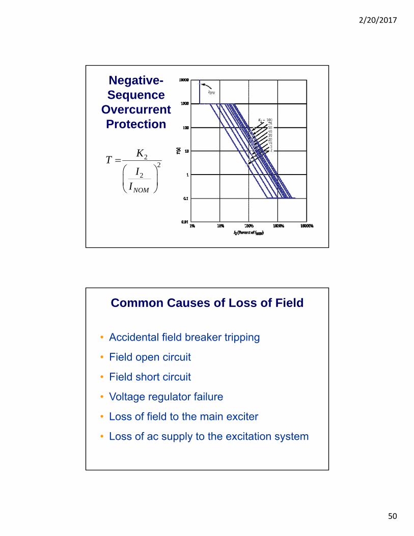
Negative-Sequence Current Capability
Short Time
Negative-Sequence Current Capability
2/20/2017
50
Negative-Sequence
Overcurrent Protection
22
2
NOM
KT
II
Common Causes of Loss of Field
• Accidental field breaker tripping
• Field open circuit
• Field short circuit
• Voltage regulator failure
• Loss of field to the main exciter
• Loss of ac supply to the excitation system
2/20/2017
51
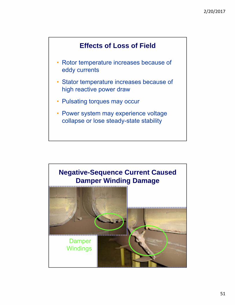
Effects of Loss of Field
• Rotor temperature increases because of eddy currents
• Stator temperature increases because of high reactive power draw
• Pulsating torques may occur
• Power system may experience voltage collapse or lose steady-state stability
Negative-Sequence Current Caused Damper Winding Damage
Damper Windings

2/20/2017
52
LOF Protection Using a Mho Element
LOF Protection Using Negative-Offset Mho Elements

2/20/2017
53
LOF Protection Using Negative- and Positive-Offset Mho Elements
Zone 2 Setting Considerations

2/20/2017
54
Possible Prime Mover DamageFrom Generator Motoring
• Steam turbine blade overheating
• Hydraulic turbine blade cavitation
• Gas turbine gear damage
• Diesel engine explosion danger from unburned fuel
Typical values of reverse power required to spin a generator at synchronous speed
Small Reverse Power FlowCan Cause Damage
Steam turbines 0.5–3%
Hydro turbines 0.2–2+%
Diesel engines 5–25%
Gas turbines 50+%

2/20/2017
55
Directional Power ElementQ
P
32P1
32P2
P1
P2
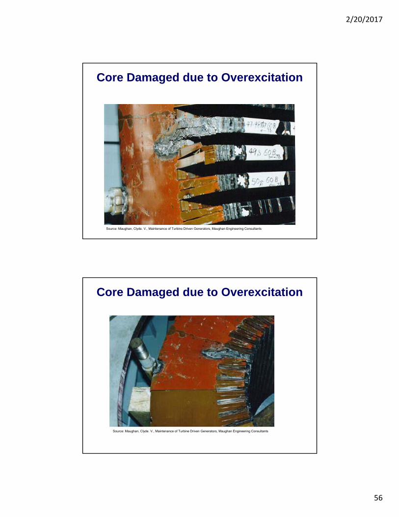
Overexcitation Protection
• Overexcitation occurs when V/f exceeds 1.05
• Causes generator heating
• Volts/hertz (24) protection should trip generator
• NOM
NOM
fV
f V
2/20/2017
56
Core Damaged due to Overexcitation
Source: Maughan, Clyde. V., Maintenance of Turbine Driven Generators, Maughan Engineering Consultants
Core Damaged due to Overexcitation
Source: Maughan, Clyde. V., Maintenance of Turbine Driven Generators, Maughan Engineering Consultants

2/20/2017
57
Overexcitation ProtectionDual-Level, Definite Time Characteristic
Overexcitation ProtectionInverse- and Definite Time Characteristics

2/20/2017
58
Overvoltage Protection
• Overvoltage most frequently occurs in hydroelectric generators
• Overvoltage protection (59):
– Instantaneous element set at 130–150 percent of rated voltage
– Time-delayed element set at approximately 110 percent of rated voltage
Abnormal Frequency Protection

2/20/2017
59
Possible Damage From Out-of-Step Generator Operation
• Mechanical stress in the machine windings
• Damage to shaft resulting from pulsating torques
• High stator core temperatures
• Thermal stress in the step-up transformer
Single-Blinder Out-of-Step Scheme
2/20/2017
60
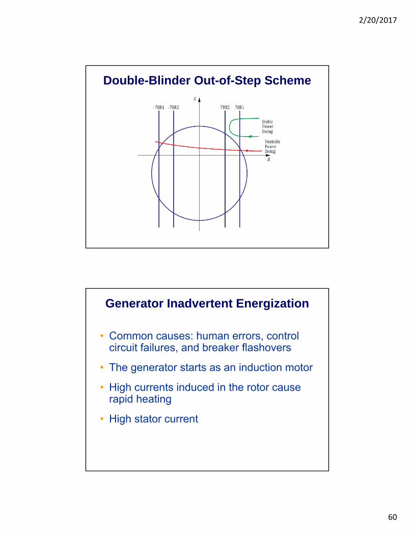
Double-Blinder Out-of-Step Scheme
Generator Inadvertent Energization
• Common causes: human errors, control circuit failures, and breaker flashovers
• The generator starts as an induction motor
• High currents induced in the rotor cause rapid heating
• High stator current

2/20/2017
61
Inadvertent Energization Protection Logic
Logic for Combined Breaker-Failure and Breaker-Flashover Protection

2/20/2017
62
Backup ProtectionDirectly Connected Generator
Generator With Step-Up Transformer
Voltage-Restrained OvercurrentElement Pickup Current

2/20/2017
63
Mho Distance Element Characteristic
Synchronism-Check Element

2/20/2017
64
Nominal Current: 10560 A
Voltage: 6.5 kV
Power System Disturbance Caused by an Out-of-Synchronism Close
Possible Damaging EffectsDuring Synchronizing
• Shaft damage due to torque
• Bearing damage
• Loosened stator windings
• Loosened stator laminations

2/20/2017
65
Source: IEEE Std. C50.12 and C50.13
IEEE Generator Synchronizing Limits
Breaker closing angle +/–10°
Generator-side voltage relative to system
100% to 105%
Frequency difference +/–0.067 Hz
Issues Affecting Generator Synchronizing
• Voltage ratio differences
• Voltage angle differences
• Voltage, angle, and slip limits
Synchronism Check relay
Synchronism Check relay

2/20/2017
66
Synchronism-Check Logic Overview