generative design of a nature-inspired geometry
TRANSCRIPT

October, 2020
ALMA MATER STUDIORUM – UNIVERSITÀ DI BOLOGNA
Department of Civil, Chemical, Environmental, and Materials Engineering
Degree program Civil Engineering – Curriculum Structural Engineering
GENERATIVE DESIGN OF A NATURE-INSPIRED GEOMETRY
MANIPULATED BY AN ALGORITHM IN A BIM-
ENVIRONMENT, APPLIED IN A FAÇADE SYSTEM FOR A
RESIDENTIAL BUILDING IN BOLOGNA, ITALY
Supervisor Author
Professor Simone Garagnani Konstantin Bozhinovski
Co-supervisor
Giacomo Bergonzoni

2
Contents
Abstract ........................................................................................................................................... 4
Keywords ........................................................................................................................................ 6
1. General introduction to the research themes ........................................................................... 7
1.1 General description of the main field of research (structures, envelopes, materials, etc.) .... 7
1.2 Expected goals and ambition............................................................................................... 10
1.3 General outline of the research work with specification of purposes for every chapter ..... 11
2. BIM technological & methodological background ............................................................... 13
Introduction ............................................................................................................................... 13
2.1 What is BIM? ...................................................................................................................... 13
2.1.1 Advantages of using BIM and BIM uses ...................................................................... 15
2.1.2 BIM Interoperability ..................................................................................................... 17
2.1.3 BIM use characteristics ................................................................................................ 19
2.2 BIM Benefits ....................................................................................................................... 20
2.2.1 Main general BIM benefits ........................................................................................... 20
2.2.2 Benefits for AEC .......................................................................................................... 20
2.3 Legal and technical risks associated with Building Information Modeling ........................ 22
2.4 Future challenges................................................................................................................. 23
2.5 Some basic principles common to guidelines and laws ...................................................... 24
2.5.1 AIA (US) regulations.................................................................................................... 24
2.5.2 PAS (UK) regulations ................................................................................................... 25
2.5.3. Italian regulations ........................................................................................................ 26
2.6 Concluding remarks ............................................................................................................ 27
3. Methodology .......................................................................................................................... 28
3.1 Function - residential building ......................................................................................... 28

3
4. Hypothesis: Implementation of the methodology created via Rhinoceros3D and Grasshopper
into a BIM environment (Revit) ................................................................................................... 32
5. Thesis: Using the algorithm created with a visual programming language and environment
(Grasshopper) that runs within the Rhinoceros3D computer-aided design (CAD) application in a
BIM environment (Revit) with a real-time preview of the result in a form of a façade system ... 33
5.1 Creating the algorithm and the geometry ............................................................................ 33
5.1.1 Experimenting and testing the methods for manipulating the geometry ...................... 33
5.1.2 Final working design for the geometry ......................................................................... 40
5.1.3 Industry foundation classes – IFC ................................................................................ 48
5.1.4 Implementation of the algorithm in a BIM environment – Revit ................................. 50
5.2 Simple roof solution using the same algorithm as a proof of concept for the workability of
the algorithm in all dimensions and directions.......................................................................... 56
5.3 Optimization of the openings of the façade system for a comfort shade benefit evaluation
regarding the analysis of the solar radiation.............................................................................. 57
6. Future application and possibilities ....................................................................................... 60
7. Conclusion ............................................................................................................................. 66
8. Bibliography .......................................................................................................................... 71

4
Abstract
Wireless communication, mobile monitoring and electronic documentation systems become
integral components of contemporary business models. In terms of technology, BIM is also part of the
worldwide change Industry 4.0, which in essence, is the trend toward automation and data exchange in
manufacturing technologies and processes.
As human designers, what can we learn from nature? One way to answer this question is to first consider
our own limitations as designers — the aspects of the design process that are particularly difficult to us as
humans. Then, we can study how design occurs in nature, and the process that natural evolution takes in
arriving at its final design solutions. With this being said, we should consider how we might develop
similar strategies within our design processes.
Contemporary designers are dealing with “Algorithms” as the model of computation to do their design
tasks. An Algorithm is a set of rules and instructions in a step by step procedure to calculate, process data
and do a defined task. For any piece of data as input, an algorithm will perform its predefined operations
and calculate the result. In this sense, a design algorithm will also provide a design output if being fed by
relevant input information. While in conventional design systems, there were various parameters (i.e. site,
program, building type, facilities, beauty, structure …) which should be considered during the design
process, in algorithmic processes it is attempted to transfer these parameters (input information) into
algorithms to generate design solutions. Furthermore, a key aspect when talking about computational
design is defining generative design and parametric design.
Generative design is an iterative design process that involves a program that will generate a certain
number of outputs that meet certain constraints, and a designer that will fine tune the feasible region by
changing minimal and maximal values of an interval in which a variable of the program meets the set of
constraints, in order to reduce or augment the number of outputs to choose from. Whereas Parametric
design is a process based on algorithmic thinking that enables the expression of parameters and rules that,
together, define, encode, and clarify the relationship between design intent and design response.
Parametric design is a paradigm in design where the relationship between elements is used to manipulate
and inform the design of complex geometries and structures.
The initial idea was to manipulate few of the most basic geometric elements in order to get a complex
parametric geometry. Inspired from the honeycomb as the natures perfectly shaped element. Two possible
explanations exist as to why honeycomb is composed of hexagons, rather than any other shape. First, the
hexagonal tiling creates a partition with equal-sized cells, while minimizing the total perimeter of the
cells.
The idea, together with the ambition to use this transformation for a façade system in a structural building
led us to a series of decisions to try and connect two “worlds”, in the sense that we have a CAD
environment that lets us create the geometry and a BIM environment where everything is represented by a
specific level of information. This geometry is given a specific set of rules that drive and manipulate each
of the elements it contains in a certain fashion. This methodology, as well as the communication and the
interaction between these softwares and environments is what makes the generative design possible.
Through a long series of testing and experimenting with the geometry, we get to a point where we have a
functional algorithm that creates and manipulates the geometry. In this algorithm every element that is

5
created has “dynamic” parameters which can be changed in an instant – which changes the result. This
result from the Grasshopper algorithm is then being created in the CAD environment in Rhinoceros3D,
which then can be opened through Rhino.Inside.Revit and give us a direct real-time preview in the BIM
environment in Revit. With a few simple tools we make the algorithm to create the geometry directly onto
an existing edge from the architectural envelope.
Thanks to BIM, it is possible to recreate a virtual building model which is not a simple 3D representation,
but a dynamic model that contains a range of information regarding: geometry, materials, load-bearing
structural members, costs, life cycle, etc.
Furthermore we have proven the eligibility of the algorithm to create the geometry in any direction in the
environment through a roughly created Roof as a proof of concept and as well as the possibility of the
process to optimize the shade comfort evaluation with the geographical coordinates of Bologna by using
the plug-in “Ladybug”.
And the last step is to consider, mention, and evaluate the future possibilities and application as a
universal method for creating complex geometry in a multiple connected environments that share and
translate the information from each other.
Design and construction of a building involving various technical roles each operating within their area of
competence. This obviously leads to the strategic importance for the various participants to exchange
information in order to effectively collaborate in the realization and management of a shared project.
And this is the main reason why the need to exchange a multidisciplinary data model arises by means of a
standard file format, allowing a secure interoperability and interchange of data without introducing errors
and/or loss of information. This is the true purpose of having the IFC data format.
The IFC, Industry Foundation Classes, is a particular data format that has the purpose to allow the inter-
exchange of an information model without loss or distortion of data.
There are 3 main ways to classify and move Rhino geometry to Revit. Each successive strategy increases
the integration within a BIM model, but each strategy also takes a bit more planning.
o DirectShapes are the most obvious and many times the easiest way to get Geometry from Rhino
into Revit.
DirectShapes are generic Revit elements that can contain and categorize arbitrary non-parametric
geometry inside the Revit model. However, since the geometry is not parametric, Revit does not know
how they are created and cannot resolved interactions between DirectShapes and other native elements.
An example is that native Revit walls cannot be extended to reach a DirectShape roof geometry.
o Developing Loadable Families with Subcategories works well for standalone elements in a model
or elements that might be ordered or built by an independent fabricator.
Being part of a Family, these objects could have their own set of drawings in addition to being part of the
larger project drawings. You can use subcategories to control the visibility and graphics of portions of a
family within a top-level category.

6
o Use Rhino geometry to generate Native Revit elements is the best way to generate final Revit
elements.
While it is not always possible to create everything with native elements, native elements normally
integrate best with the rest of the Revit team. These objects can potentially be edited without any
dependency on Rhino.Inside.Revit. While the creating elements in this way can be limited, the resulting
elements are native Revit elements. Using built-in Revit System Families such as Walls, Floors, Ceilings,
and Roofs can take the most amount of thought, however, the extra effort can be worth it.
We discussed at length about the advantages and possibilities of BIM as a process but for the creation of
the thesis and its future application “openBIM” comes to mind. When we think and discuss the future
application we have to, in a way, “expand” the possibilities of the process and algorithm that we created
and consider them to be “openBIM” compliant.
“openBIM” extends the benefits of BIM (Building Information Modeling) by improving the accessibility,
usability, management, and sustainability of digital data in the built asset industry. At its core, openBIM
is a collaborative process that is vendor neutral. openBIM processes can be defined as sharable project
information that supports seamless collaboration for all project participants. openBIM facilitates
interoperability to benefit projects and assets throughout their lifecycle.
Keywords:
BIM – Building Information Modeling, Computational design, Parametric design, Generative design,
BIM environment, Revit, Rhinoceros3D, Grasshopper, Rhino.Inside.Revit, Visual programming
language, CAD environment, Parametric geometry, Façade system, Shade optimization, Algorithm, AEC,
IFC - Industry foundation classes, OpenBIM.

7
1. General introduction to the research themes
1.1 General description of the main field of research (structures, envelopes,
materials, etc.)
Computational design is the application of computational strategies to the design
process. While designers traditionally rely on intuition and experience to solve design problems,
computational design aims to enhance that process by encoding design decisions using a
computer language. The goal is not to document the final result necessarily, but rather the steps
required to create that result. Most computational design environments rely on visual
programming as opposed to traditional text-based programming. With visual programming, you
assemble programs graphically rather than writing code. Outputs from one node are connected to
inputs on another. A program or “graph” flows from node to node along a network of connectors.
The result is a graphic representation of the steps required to achieve the end design.By using a
computational design process, you are encoding the design. Each step in the design becomes a
series of instructions that can be evaluated, revised, and improved. Likewise, each step requires
specific parameters. By thinking through all the steps of the design problem and considers all the
inputs and outputs, you effectively create a process that can be understood and repeated.
It is widely discussed, criticized, attempted, and somehow admitted that contemporary
engineering or architecture as other areas of human activities like media, entertainment, science
and technology, is dominated by computers and “Computation” paradigm. In Design Industry,
computers were first appeared as helping tools for facilitation of manual tasks which started the
procedure of “Computerization” through utilization of PC’s and CAD software (Terzidis, 2006)
in offices. While the notion of computerization was the first step, utilization of computers is now
certainly evolved into the era of “Computation” in design processes (which tremendously
affected the “design thinking”) (Menges, 2010). In this sense, computation refers to the act of
calculation and reasoning in the information processing. It involves certain techniques and
methods which deal with the subjects, processes and tasks that could be done through
information processing and even raises the question of Computability and Incomputability
(Flake, 1998).

8
Contemporary designers are dealing with “Algorithms” as the model of computation to do their
design tasks. An Algorithm is a set of rules and instructions in a step by step procedure to
calculate, process data and do a defined task. For any piece of data as input, an algorithm will
perform its predefined operations and calculate the result. In this sense, a design algorithm will
also provide a design output if being fed by relevant input information. While in conventional
design systems, there were various parameters (i.e site, program, building type, facilities, beauty,
structure …) which should be considered during the design process, in algorithmic processes it is
attempted to transfer these parameters (input information) into algorithms to generate design
solutions.
Furthermore, a key aspect when talking about computational design is defining generative design
and parametric design.
Generative design is an iterative design process that involves a program that will generate a
certain number of outputs that meet certain constraints, and a designer that will fine tune
the feasible region by changing minimal and maximal values of an interval in which a variable of
the program meets the set of constraints, in order to reduce or augment the number of outputs
to choose from. The program doesn't need to be run on a machine like a digital computer, it can
be run by a human for example with pen and paper. The designer doesn't need to be a human, it
can be a test program in a testing environment or an artificial intelligence, for example
a generative adversarial network. The designer learns to refine the program (usually
involving algorithms) with each iteration as their design goals become better defined over time.
Whereas, Parametric design is a process based on algorithmic thinking that enables the
expression of parameters and rules that, together, define, encode and clarify the relationship
between design intent and design response. Parametric design is a paradigm in design where the
relationship between elements is used to manipulate and inform the design of complex
geometries and structures.
The term parametric originates from mathematics (parametric equation) and refers to the use of
certain parameters or variables that can be edited to manipulate or alter the end result of an
equation or system.

9
As human designers, what can we learn from nature? One way to answer this question is to first
consider our own limitations as designers — the aspects of the design process that are
particularly difficult to us as humans. Then, we can study how design occurs in nature, and the
process that natural evolution takes in arriving at its final design solutions. With this being said,
we should consider how we might develop similar strategies within our design processes.
For example, the New Terminal 3 at Shenzhen Bao’an International Airport, China. A “manta
ray emerging from the depths of the sea, transformed into a bird and ascending into the sky” –
this is how Massimiliano and Doriana Fuksas describe their design for the new Terminal 3. The
terminal building is clad by an organically shaped, double-skin envelope covering the structure.
The outer and inner skins, each perforated by approx. 25 000 honeycomb-shaped openings,
allows for bright but diffused and patterned natural light.
Two major decisions guaranteed that every passenger would have an unobstructed view out over
the airfield: At the competition phase it became clear that the structure should be aligned with the
logic of the honeycomb façade, which meant that the structure had to follow the diagonal
orientation. Otherwise, verticals and horizontals would cut through the windows. As a second
aspect, a “ray” system was developed to define the geometry of the concourse section. The
façade openings and main structure were oriented to allow horizontal views through the façade
from all locations on the departure level.
Inspired from the honeycomb as the natures perfectly shaped element, the idea is to create an
algorithm that follows the behavior of a simple shape as the hexagon into a form or a surface
which is consisted of repeatedly combined hexagon shapes with a very stable connection in-
between.

10
A honeycomb is a mass of hexagonal prismatic wax cells built by honey bees in their nests to
contain their larvae and stores of honey and pollen.
Two possible explanations exist as to why honeycomb is composed of hexagons, rather than any
other shape. First, the hexagonal tiling creates a partition with equal-sized cells, while
minimizing the total perimeter of the cells. Known in geometry as the honeycomb conjecture,
this was given by Jan Brożek and proved much later by Thomas Hales. Thus, a hexagonal
structure uses the least material to create a lattice of cells within a given volume.
1.2 Expected goals and ambition
In our specific case we have to apply a parametric geometry onto a residential building in
Bologna, Italy as a façade system which we can manipulate with the algorithm depending on the
primary needs of the project and its uses.
It is very interesting that we need to collide 2 completely different worlds into 1 environment
that can communicate with both worlds, translate each of their information and combine it
together in 1 functional result that follows the patterns and rule it is previously given into 2
separate environments.
In order to create this whole process, we have to find a way to combine multiple environments
that interact and communicate with each other. We start from a BIM environment where we also
want to get the final result, but we have to introduce another different environment where the

11
geometry won’t be so “static” as in Revit, but instead it will follow a given specific rule that
changes the geometry according to its predefined laws. This can be done by introducing a visual
programming language and environment (Grasshopper) that runs within the Rhinoceros3D
computer-aided design (CAD) application. These software’s are much more suitable for creating
a so-called “free-form” geometry than directly using Revit (and its Adaptive components as a
method) and the communication between Grasshopper and Rhinoceros3D is very stable. So, if
we want to work with a “dynamic” geometry or in other words, a parametric geometry we
actually need to start with Grasshopper and work our way to the BIM environment in Revit step-
by-step. This means that if we want to have a workable parametric geometry in Revit, we have to
learn how to work with a visual programming language and environment, then to understand
how that language is transformed and placed into a CAD application, and lastly when we need to
have the information from Rhinoceros3D placed into Revit, we can use the specific plug-in
called “Rhino Inside” which basically translates the information and gives us a preview of our
result in a BIM environment.
1.3 General outline of the research work with specification of purposes for
every chapter
In this paper I will discuss the process of creating an algorithm for a generative design of
a geometry that eventually will serve as a façade system in a residential building in Bologna,
Italy.
In the first chapter we have briefly explained the initial idea, the motivation behind that idea and
the basic steps that we plan to take throughout the whole thesis by means of experimentation and
testing various types of processes and methods. With these steps we are gathering information on
how and why these methods do or do not work, which will be explained in detail along the
research. Furthermore, in this chapter we are providing the information on which software’s we
will use and the reason why we have to work in those specific environments with their tools and
possibilities.
In the second chapter we are introducing the readers to the BIM technology. This is where we
have a very thorough and detailed introduction into the BIM world, its history, development,

12
and, as well as its advantages and disadvantages. Most importantly, in this chapter we cover the
interoperability that BIM offers and its future challenges.
The third chapter is the methodology of the thesis. This is where we specifically explain where
and what for do we plan to use all the previously mentioned tools and processes. The function of
our algorithm in a residential area, as well as identifying its issues with the same.
The 4th chapter is where we define our hypothesis which is the implementation of the
methodology created via Rhinoceros3D and Grasshopper into a BIM environment (Revit). This
is the main chapter where we specifically introduce the readers about what we want to do, why
we want to do it and how we plan to do it.
Chapter number 5 is the thesis. In this chapter we have a step-by-step guide about the algorithm,
the process, the tools used, how all the previously encountered problems were solved and, of
course, the final result. Furthermore, all the interactions and communications between all 3
environments are explained as to how they work together to create our final product.
This chapter also covers the universal use of the created algorithm, in a form of a very simple
roof geometry with which we prove that the algorithm is adaptable in any direction in our 3D
environment and last, but not least, we performed solar radiation analysis with a plug-in
“Ladybug” that gave us information (using the geographical coordinates of the city of Bologna)
on how we can perform an optimization of the shade values of our façade system.
In the 6th chapter we discuss the future application and possibilities of our algorithm. Since the
algorithm is basically universal, here we discuss a few of the many possibilities where this
algorithm can be applied and what for can it be used.
The 8th chapter is our conclusion where we draw the main advantages of the algorithm and the
main advantages of combining 2 complex worlds together.
13
2. BIM technological & methodological background
Introduction
In the 21st century, evolution in computer science has changed the work process of almost
every industry. Wireless communication, mobile monitoring and electronic documentation
systems become integral components of contemporary business models. In terms of technology,
BIM is also part of the worldwide change Industry 4.0, which in essence, is the trend toward
automation and data exchange in manufacturing technologies and processes.
BIM is an information technology enabled approach that involves applying and maintaining an
integral digital representation of all building information for different phases of the complex
construction project lifecycle (Chen & Qu, 2011) in the form of a data repository (Gu & London,
2010). BIM manages both graphical perspectives and building information, allowing the
computer-aided generation of drawings and reports, design evaluation, project scheduling and
resources organization from facility design to operation.
2.1 What is BIM?
Building Information Modeling (BIM) is an intelligent 3D model-based process that
gives architecture, engineering, and construction (AEC) professionals the insight and tools to
more efficiently plan, design, construct and manage buildings and infrastructure.
The concept of BIM has existed since the 1970s. The term “building model” was first used in
papers in the mid-1980s by Simon Ruffle and later by Robert Aish, while the term “Building
Information Model” first appeared in a 1992 paper by G.A. van Nederveen and F. P. Tolman.
In 2002, Autodesk released a white paper entitled “Building Information Modeling”, and other
software vendors also started to assert their involvement in the field. By hosting contributions
from Autodesk, Bentley Systems and Graphisoft, in 2003, Jerry Laiserin helped popularize and
standardize the term as a common name for the digital representation of the building process.
Seeing buildings through the lens of the database contributed to the breakdown of architecture
into its constituent components, necessitating a literal taxonomy of a buildings constituent parts.

14
One of the first projects to successfully create a building database was the Building Description
System (BDS) which was the first software to describe individual library elements which can be
retrieved and added to a model. This program uses a graphical user interface, orthographic and
perspective views and a sortable database that allows the user to retrieve information
categorically by attributes including material type and supplier. The project was designed by
Charles Eastman.
Charles M. Eastman is a professor in the Colleges of Design and Computer Science at Georgia
Institute of Technology. He is a specialist in the areas of Building information modeling, solid
and parametric modeling, engineering databases, and product models and interoperability. He is
the director of the Georgia Tech Digital Building Lab (DBL).
Eastman is a pioneer of AEC CAD, developing research 3D and early solid and parametric
modeling systems for the building industry starting in the middle 1970s. Trained as an architect
at the Berkeley CED, he focused on tool development for practitioners with the 'Building
Description System' and 'Building Product Modeling', later re-branded as Building Information
Modeling. He started the PhD program in Architecture at Carnegie Mellon University and
founded ACADIA (the North American academic building modeling conference group). He did
a parametric modeling start-up (called FORMTEK) in the early 1980s and then joined University
of California, Los Angeles, where he was for eight years before coming to Georgia Tech.
His research group at GA Tech works with industry groups to develop new generation
parametric modeling tools and also new integrating tools and workflows. He currently has
projects with the Precast Concrete Institute and the Charles Pankow Foundation, with GSA,
working on courthouse BIM tools, with the American Institute of Steel Construction and
the American Concrete Institute, defining BIM exchange standards for these industry areas. He
recently completed work with the National Institute of Standards and Technology on improving
IFC semantic foundations.

15
2.1.1 Advantages of using BIM and BIM uses
While the reasons for the uses of BIM may be broad, common goals include improving
design, management processes, project time efficiency, and constructability of a project.
Essentially, a BxP1 must state why BIM is being used so that everyone involved with the project
can have a clear goal to work towards. This will limit extraneous work and keep the contributors
focused on the same goal.
There are many use cases of BIM as teams begin considering their BxP’s. Penn State University
is a leader in BIM research and has studied the Use of BIM across organizations. Their results
identify four main life-cycle stages of a project: Planning, Design, Construction and Operations.
Some of the most common uses of BIM identified are 3D coordination, site layout drawings,
assistance in marketing, and the creation of design and construction (“shop”) drawings.
1 BxP – Rule Book of a Construction Project

16
o Existing conditions modeling
A process in which a project team develops a 3D model of the existing conditions for a site,
facilities on a site, or a specific area within a facility. This model can be developed in multiple
ways including laser scanning, photogrammetry and/or conventional surveying techniques,
depending on what is desired and what is most efficient. Once the model is constructed, it can be
queried for information, whether it is for new construction or a modernization project.
o Cost estimation
A process in which BIM can be used to assist in the generation of accurate quantity take-offs and
cost estimates throughout the lifecycle of a project. This process allows the project team to see
the cost effects of their changes, during all phases of the project, which can help curb excessive
budget overruns due to project modifications. Specifically, BIM can provide cost effects of
additions and modifications, with potential to save time and money and is most beneficial in the
early design stages of a project.
o Phase Planning (4D Modeling)
A process in which a 4D model (3D models with the added dimension of time) is utilized to
effectively plan the phased occupancy in a renovation, retrofit, addition, or to show the
construction sequence and space requirements on a building site. 4D modeling is a powerful
visualization and communication tool that can give a project team the including owner a better
understanding of project milestones and construction plans.
o Structural Analysis
A process in which analytical modeling software utilizes the BIM design authoring model so to
determine the behavior of a given structural system. With the modeling minimum required
standards for structural design and analysis are used for optimization. Based on this analysis
further development and refinement of the structural design takes place to create effective,
efficient, and constructible structural systems. The development of this information is the basis
for what will be passed onto the digital fabrication and construction system design phases.
This BIM Use does not need to be implemented from the beginning of the design to be
beneficial. Often structural analysis is implemented at the connection design level to make

17
fabrication quicker, more efficient and for better coordination during construction. Another
application is that this relates and ties into is construction system design, examples include but
not limited to: erection design, construction means and methods, and rigging. The application of
this analysis tool allows for performance simulations that can significantly improve the design,
performance, and safety of the facility over its lifecycle.
2.1.2 BIM Interoperability
Interoperability is the ability to communicate between varying types of software. It has
become a buzzword for the architecture, engineering and construction (AEC) industry.
Or, in other words, interoperability is a characteristic of a product or system, whose interfaces
are completely understood, to work with other products or systems, present or future, in either
implementation or access, without any restrictions. As our built environment becomes more
digitized and relies more heavily on technology like building information modeling (BIM), it
becomes increasingly dependent on interoperability.

18
As mentioned in a paper from Penn State University, one of the most important ability that is
enabling interoperability is to Transform, or in other words: to modify information and translate
it to be received by another process which is a synonym for Translate.
Often within the BIM process, facility information needs to be taken from one form to another so
that it can be received and used by another process. This translation or transformation of data
allows for interoperability between different systems. It also allows legacy data to be used by
current infrastructure. Some examples include developing spooling information, developing
layout data, and developing industry standard formats. Often this translated data is in manner in
which it is not human interoperable, but readable by machine.

19
2.1.3 BIM use characteristics
BIM Use Characteristics are used to define the BIM Use more precisely beyond the
purpose and objective alone. This includes the facility element(s), facility phase(s), discipline(s),
and level of development.
Adding these characteristics move the BIM Use beyond answering “why” to a more distinct
description which could be used in procurement efforts. Additionally, when BIM planning, a
team can communicate to all the stake holders who, what, when, and to what degree the BIM
Use will be implemented. Depending on the facility’s BIM utilization, it is possible to have
multiple disciplines implement multiple BIM Use purposes during multiple phases on multiple
facility elements to multiple levels of development.
o Level of development
For each of the BIM Uses, the level of development should be identified in order to maximize
the benefit from the BIM Use. The Level of Development describes the level of detail /
granularity to which a Model Element is developed. AIA / BIMForum has recently released a
major revision to the level of development specification. This revision further specifies level of
development for specific elements of the facility with details in Figure 2.

20
2.2 BIM Benefits
2.2.1 Main general BIM benefits
The key benefit of BIM is its accurate geometrical representation of the parts of a building in
an integrated data environment (CRC Construction Innovation, 2007).
Other related benefits are:
o Faster and more effective processes – information is more easily shared, can be value-
added and reused.
o Better design – building proposals can be rigorously analyzed, simulations can be
performed quickly and performance benchmarked, enabling improved and innovative
solutions.
o Controlled whole-life costs and environmental data – environmental performance is more
predictable; lifecycle costs are better understood.
o Automated assembly – digital product data can be exploited in downstream processes and
be used for manufacturing/assembling of structural systems.
o Better customer service – proposals are better understood through accurate visualization.
o Lifecycle data – requirements, design, construction and operational information can be
used in facilities management.
2.2.2 Benefits for AEC
The Architecture, Engineering and Construction (AEC) industries have long sought
techniques to decrease project cost, increase productivity and quality, and reduce project delivery
time. Building Information Modeling (BIM) offers the potential to achieve these objectives. BIM
represents the development and use of computer-generated n-dimensional (n-D) models to
simulate the planning, design, construction and operation of a facility. It helps architects,
engineers and constructors to visualize what is to be built in simulated environment and to
identify potential design, construction or operational issues. BIM represents a new paradigm

21
within AEC, one that encourages integration of the roles of all stakeholders on a project. It has
the potential to bring about great efficiency as well as harmony amongst the people working on
the project.
Building Information Modeling (BIM) is one of the most promising developments in the
Architecture, Engineering and Construction (AEC) industries. BIM simulates the construction
project in a virtual environment. With BIM technology, an accurate virtual model of a building is
digitally constructed. When completed, the computer-generated model contains precise geometry
and relevant data needed to support the construction, fabrication and procurement activities
required to realize the building. A Building Information Model, is a data-rich, object-oriented,
intelligent and parametric digital representation of the facility, from which views and data
appropriate to various users’ needs can be extracted and analyzed to generate information that
can be used to make decisions and to improve the process of delivering the facility (AGC, 2005).
The principal difference between BIM and conventional 3D CAD is that the latter describes a
building by independent 3D views such as plans, sections and elevations. Editing one of these
views requires that all other views must be checked and updated, an error-prone process that is
one of the major causes of poor documentation. In addition, data in these 3D drawings are
graphical entities only, such as lines, arcs and circles, in contrast to the intelligent contextual
semantic of BIM models, where objects are defined in terms of building elements and systems
such as spaces, walls, beams and columns. A building information model carries all information
related to the building, including its physical and functional characteristics and project life cycle
information, in a series of “smart objects”. For example, an air conditioning unit within a BIM
would also contain data about its supplier, operation and maintenance procedures, flow rates and
clearance requirements.
It is important to note that a building information model characterizes the geometry, spatial
relationships, geographic information, quantities and properties of building elements, cost
estimates, material inventories and project schedule. This model can be used to demonstrate the
entire building life cycle (Bazjanac, 2006). As a result, quantities and shared properties of
materials can be readily extracted. Scopes of work can be easily isolated and defined. Systems,
assemblies, and sequences can be shown in a relative scale with the entire facility or group of
facilities. The construction documents such as the drawings, procurement details, submittal

22
processes and other specifications can be easily interrelated. A building information model can
be used for the following purposes:
o Visualization: 3D renderings can be easily generated in-house with little additional
effort.
o Fabrication/shop drawings: it is easy to generate shop drawings for various building
systems, e.g., the sheet metal ductwork shop drawing can be quickly produced once the
model is complete.
o Code reviews: fire departments and other officials may use these models for building
projects review.
o Forensic analysis: a building information model can easily be adapted to graphically
illustrate potential failures, leaks, evacuation plans, etc.
o Facilities management: facilities management departments can use BIM for
renovations, space planning, and maintenance operations.
o Cost estimating: BIM software(s) have built-in cost estimating features. Material
quantities are automatically extracted and changed when any changes are made in the
model.
o Construction sequencing: a building information model can be effectively used to
create material ordering, fabrication, and delivery schedules for all building
components.
o Conflict, interference and collision detection: because BIM models are created, to scale,
in 3D space, all major systems can be visually checked for interferences. This process,
formally called “Clash detection”, can verify that piping does not intersect with steel
beams, ducts or walls.
2.3 Legal and technical risks associated with Building Information Modeling
The first legal risk to determine is ownership of the BIM data and how to protect it through
copyright laws. For example, if the owner is paying for the design, then the owner may feel
entitled to own it, but if team members are providing proprietary information for use on the -
project, their propriety information needs to be protected as well. Thus, there is no simple answer

23
to the question of data ownership; it requires a unique response to every project depending on the
participants' needs. The goal is to avoid inhibitions that discourage participants from fully
realizing the model's potential (Thompson, 2001). Another issue to address is who will control
the entry of data into the model and be responsible for any inaccuracies in it. Taking
responsibility for updating BIM data and ensuring its accuracy entails a great deal of risk.
Requests for complicated indemnities by BIM users and the offer of limited warranties and
disclaimers of liability by designers will be essential negotiation points that need to be resolved
before BIM technology is utilized. It also requires more time spent imputing and reviewing BIM
data, which is a new cost in the design and project administration process. Although these new
costs may be more than offset by efficiency and schedule gains, they are still a cost that someone
on the project team will have to bear. Thus, before BIM technology can be fully utilized, the
risks of its use must not only be identified and allocated, but the cost of its implementation must
be paid for as well (Thompson and Miner, 2007). The integrated concept of BIM blurs the level
of responsibility so much that risk and liability will likely be enhanced.
2.4 Future challenges
The productivity and economic benefits of BIM to the AEC industry are widely
acknowledged and increasingly well understood. Further, the technology to implement BIM is
readily available and rapidly maturing. Yet, BIM adoption is much slower than anticipated
(Fischer and Kunz, 2006). There are two main reasons, technical and managerial. The technical
reasons can be broadly classified into three categories (Bernstein and Pittman, 2005):
o the need for well-defined transactional construction process models to eliminate data
interoperability issues;
o the requirements that digital design data be computable;
o the need for well-developed practical strategies for the purposeful exchange and
integration of meaningful information among the BIM model components.
The management issues cluster around the implementation and use of BIM. There is a need to
standardize the BIM process and to define the guidelines for its implementation. Another

24
contentious issue among the AEC industry stakeholders (i.e. owners, designers and constructors)
is who should develop and operate the building information models and how should the
developmental and operational costs be distributed.
2.5 Some basic principles common to guidelines and laws
2.5.1 AIA (US) regulations
As the use of building information modeling (BIM) and other types of DigitalData has
continued to evolve in the design and construction industry in recent years, the industry has
begun to ask practical questions regarding how these concepts and tools should be implemented.
In an effort to provide guidance, the American Institute of Architects (AIA) published its first
Digital Data documents, AIA Documents E201™–2007, DigitalData Protocol Exhibit, and
C106™–2007, DigitalData Licensing Agreement, in October 2007. E201–2007 is an exhibit to
an agreement that allows the parties to establish the procedures they agree to follow with respect
to the transmission or exchange of DigitalData, including instruments of service. Unlike E201–
2007, C106–2007 is not an exhibit and is instead a stand-alone agreement between two parties
who otherwise have no existing licensing agreement for the use and transmission of Digital Data,
including Instruments of Service. Following the release of E201–2007, the AIA addressed the
increasing use of BIM with the publication of AIA Document E202™–2008, Building
Information Protocol Exhibit.
Like E201–2007, E202–2008 is an exhibit that is attached to the parties’ agreement. E202–2008
is used to establish the requirements for model content at five progressive levels of development,
and the authorized uses of the model content at each level of development. E202–2008 also
assigns authorship of each model element by project phase, defines the extent to which model
users may rely on model content, clarifies model ownership, sets forth BIM standards and file
formats, and provides the scope of responsibility for model management from the beginning to
the end of the project.
Digital practice and the use of BIM are rapidly evolving areas of the industry. Typically AIA
Contract Documents are revised on a ten year cycle. However, given the pace at which use of

25
Digital Data in the construction industry is changing, a ten year review cycle for the Digital
Practice documents would have been too long, to maintain a meaningful tool for industry
participants. Accordingly, in 2011 the AIA undertook to again evaluate continued development
and adoption of digital practice and BIM. As a result of this evaluation, the AIA created an
updated and reconfigured new set of Digital Practice documents that includes AIA Document
E203™–2013, Building Information Modeling and DigitalData Exhibit; AIA DocumentG201™
2013, Project DigitalData Protocol Form; and AIA Document G202™ 2013, Project Building
Information Modeling Protocol Form. This Guide, Instructions and Commentary to the 2013
AIA Digital Practice Documents (the “Guide”) is intended to provide an in-depth look at this set
of Digital Practice documents, and to provide guidance on how the documents are intended to be
used.
2.5.2 PAS (UK) regulations
The PAS 1192 framework sets out the requirements for the level of model detail (the
graphical content), model information (non-graphical content, such as specification data), model
definition (its meaning) and model information exchanges.
As a whole the series currently contains:
o PAS 1192-2: 2013, which deals with the construction (CAPEX) phase, and specifies the
requirements for Level 2 maturity; sets out the framework, roles and responsibilities for
collaborative BIM working; builds on the existing standard of BS 1192, and expands the
scope of the Common Data Environment (CDE).
o PAS 1192-3: 2014, which deals with the operational (OPEX) phase, focusing on use and
maintenance of the Asset Information Model, for Facilities Management.
o BS 1192-4: 2014, technically a code of practice rather than a specification standard,
which documents best practice for the implementation of COBie2.
o PAS 1192-5: 2015, a specification for security-minded building information modelling,
digital built environments and smart asset management.
2 COBie – Construction Operations Building Information Exchange
26
2.5.3. Italian regulations
Through the new D.l. 50, in April 2016 Italy has included into its own legislation several
European directives including 2014/24/EU on Public Procurement. The decree states among the
main goals of public procurement the "rationalization of designing activities and of all connected
verification processes, through the progressive adoption of digital methods and electronic
instruments such as Building and Infrastructure Information Modelling". A norm in 8 parts is
also being written to support the transition: UNI 11337-1, UNI 11337-4 and UNI 11337-5 were
published in January 2017, with five further chapters to follow within a year.
In early 2018 the Italian Ministry of Infrastructure and Transport issued a decree (DM 01/12/17)
creating a governmental BIM Mandate compelling public client organizations to adopt a digital
approach by 2025, with an incremental obligation which will start on 1 January 2019.
Parts 1, 4 and 5 of standard UNI 11337 Construction and civil engineering works - Digital
management of information processes of buildings published by the Technical Commission
Products, processes and systems for the building organization.
o UNI 11337-1: 2017 "Construction and civil engineering works - Digital management of
building information processes - Part 1:
“Models, designs and information objects for products and processes" concerns the general
aspects of digital management of the information process in the field of constructions, such as:
the structure of the information vehicles, the information structure of the process, the information
structure of the product.
The standard is applicable to any type of (resulting) product in the sector, be it a building or an
infrastructure, and to any type of process: from conception, production or operation. They are
aimed at new construction as at the conservation and / or requalification of the environment or
built heritage.

27
o UNI 11337-4: 2017 "Construction and civil engineering works - Digital management of
building information processes - Part 4:
“Evolution and information development of models, designs and objects" concerns the
qualitative and quantitative aspects of the digitalized management of the information process in
the construction sector, to support the decision-making process, with the aim of: specifying the
objectives of each of the phases of a process (numbered from 0 to 7) introduced in UNI 11337-1.
The model, objects and information documents are instrumental in achieving these objectives;
define a common level of information development level of the objects related to the models;
define a common scale of processing states and approval of the information content.
The UNI 11337-4 standard is applicable to any type of product (resulting) in the sector (be it a
building, an infrastructure, a territorial intervention - for example a basin, a cliff, etc.) and to any
type of process (of conception , production or operating), for new construction and conservation,
demolition and / or redevelopment of the environment or built heritage.
o UNI 11337-5: 2017 "Construction and civil engineering works - Digital management of
information processes in buildings - Part 5:
“Information flows in digitized processes" defines the roles, rules and flows necessary for
production, management and transmission of information and its connection and interaction in
digitized construction processes.
2.6 Concluding remarks
Building Information Modeling (BIM) has emerged as an innovative way to manage projects.
Many researchers and practitioners have indicated that the BIM technology is set to become as
indispensable to building design and construction as the proverbial tee square or hammer and
nail. As the use of BIM accelerates, collaboration within project teams should increase, which
will lead to improved profitability, reduced costs, better time management and improved
customer/client relationships.

28
3. Methodology
3.1 Function - residential building
A residential building is defined as the building which provides more than half of its floor
area for dwelling purposes. In other words, residential building provides sleeping
accommodation with or without cooking or dining or both facilities.
We have several types of residential buildings and they are divided into the following types:
o Individual houses or private dwellings
o Lodging or rooming houses
o Dormitories
o Apartments
o Hotels
Our case belongs to the Apartments category, which are, by definition, big buildings which
consists separate dwellings for different families. This means that we will have minimum three
or more families living independently of each other.
The site selection for residential buildings is a very important and experts’ job and should be
done very carefully by an experienced engineer. The requirements of site for buildings of
different category are various, but we should mention the following general requirements:
o The site should be in fully developed area or in the area which has potential of
development
o There should be good transport facilities such as railway, bus service, for going to office,
college, market, etc.
o Civic services such as water supply, drainage sewers, electric lines, telephone lines, etc.
should be very near to the selected site so as to obtain their services with no extra cost.
o The selected site should be large enough; both to ensure the building abundant light and
air to prevent any over dominance by the neighboring buildings.
29
o Nearness of schools, hospitals, etc. are considered good for residential site, but these
facilities do not carry any significance in the selection site for other public buildings.
o Residential buildings should be located away from the busy commercial roads.
Furthermore, we should speak for the Italian regulations more thoroughly. Generally speaking,
we can initially divide the regulations in 2 groups - Residential and Commercial.
In Italy there is no specific general regulation for residential building because there are many and
they almost always change among regions, so we need to introduce BIM laws only (D Lgs
50/2016 and DM 560/2017, which however are mandatory for the public procurement only.
From the 29.01.2018 DRAFTING, we can say that we have in force the MIT Decree 01.12.2017
n. 560 which establishes the methods and times for the gradual introduction of electronic
modeling methods and tools for buildings and infrastructures.
In implementation of art. 23, paragraph 13, of the Legislative Decree 18.04.2016 n. 50 (Code of
public contracts ") the Decree defines the methods and times for the gradual introduction, by
contracting authorities, granting administrations and economic operators, of the mandatory
nature of specific electronic methods and tools, such as modeling tools for construction and
infrastructure, in the design, construction and management phases of the works and related
checks.
From the date of entry into force of the Decree, contracting authorities can optionally request the
use of electronic methods and tools for new works as well as for recovery, redevelopment or
changes.
Contracting authorities, on the other hand, mandatorily require the use of electronic methods and
tools according to the following timing:
a) for complex works relating to works with a tender amount equal to or greater than 100
million euros, starting from 1 January 2019;
b) for complex works relating to works with a tender amount equal to or greater than € 50
million starting from 1 January 2020;

30
c) for complex works relating to works with a tender amount equal to or greater than 15
million euros starting from 1 January 2021;
d) for works with a tender-based amount equal to or greater than the threshold referred to in
Article 35 of the Public Contracts Code, starting from 1 January 2022;
e) for works with a tender amount equal to or greater than 1 million euro, starting from 1
January 2023;
f) for works with a tender amount of less than 1 million euros, starting from January 1,
2025.
What are the building and planning permit requirements for an Italian property?
In Italy you need to comply with building rules and regulations in order to do any construction
work on an Italian property. For example, you typically need permits to build a property, to add
an extension, for renovations as well as remodeling work, even small projects. If you do not
comply with the construction work rule above, there might be a case of building violation.
Depending on the nature and entity of the work to be done, or work that has already been done,
you might need to pursue one of the following options:
o Building Notice: If you do minor work, without any impact, or with nominal impact, on
zoning and property value that does not make a substantial alteration to the property
surface area, you need to notify the local Municipal authority about the work that needs
to be done. The Italian term for such notice depends on specific case circumstances.
Common notices are: Dichiarazione di Inizio attività (or DIA), or Comunicazione di
Inizio Lavori – (CIL/CILA) or Segnalazione Certificata di Inizio Lavori (SCIA).
o Building Permit (Permesso di Costruire): If you do more substantial work you need a
Building Permit. You need to apply for a Permit, and it needs to be granted, prior to
starting the work.
o Formal Building Amnesty (Permesso in Sanatoria, or just Sanatoria): If you start the
construction work without a notice or a building permit, you might be able to regularize
your position by filing a Sanatoria. You file a Formal Building Amnesty (Sanatoria) to
update the property record. You can apply for a Formal Building Amnesty when the work
done is not in conflict with mandatory rules and regulations. You cannot get a Sanatoria
31
if, for example, you have done work that, had you asked for a permit, it would have been
denied.
o Substantial Building Amnesty (Condono Edilizio, or Condono): If you have done work
that goes against local building rules and you cannot get a Formal Building Amnesty
(Sanatoria), you might be able to fix the situation through a Condono. A Condono is
possible only if the government passes a special Condono law that determines the
applicable terms. In the past the government established deadlines to file Condono
applications for certain types of building violations done before a certain date.

32
4. Hypothesis: Implementation of the methodology created via Rhinoceros3D
and Grasshopper into a BIM environment (Revit)
The initial idea made on the basis of limited evidence as a starting point for further
investigation, was to try to create a parametric geometry that we will be able to manipulate in
some pattern which we choose and that will follow a specific set of rules that we impose. So, we
wanted to start from the most basic geometry and try to evolve it into something much more
complex and advanced. Considering this, we had to choose an environment where we can freely
manipulate the geometry and that is why we chose Rhinoceros3D, because it gives us as a
designer a very wide range of commands and possibilities on how to work with the geometry.
After choosing the CAD environment, because we want to make the geometry as “dynamic” as
possible, we needed an additional software that is able to imply a set of rules that will govern the
transformation/manipulation of the geometry. That is why for this task we choose Grasshopper, a
visual programming language and environment that is firstly able to complete this task for us,
and secondly – it is the most compatible software that works with Rhino. With Grasshopper and
its environment, we can make sure that we can create the set of rules that define and drive the
geometry, in other words – the algorithm. The last piece of the puzzle is how to give this
geometry enough information as a parameter so it can be universal and so it can act as a very
wide range of material or to have a different function depending on the specific needs for each
project that it will be used for. For this purpose, the idea is to transfer the result from the CAD
environment which was generated by the algorithm – into a BIM environment where the
geometry will gain the advantage of having as much information as possible. In this stage we
introduce Revit, as a software that can receive and translate the given result and use it in its own
environment.

33
5. Thesis: Using the algorithm created with a visual programming language
and environment (Grasshopper) that runs within the Rhinoceros3D
computer-aided design (CAD) application in a BIM environment (Revit)
with a real-time preview of the result in a form of a façade system
5.1 Creating the algorithm and the geometry
5.1.1 Experimenting and testing the methods for manipulating the geometry
In order to create the basic element which will shape all the geometry for the idea, I started
from the simplest form – a cube. The cube is easily manipulated into many different shapes, for
which in our case – we want the end result to be a hexagon. Since the idea is to create a shape
that will most likely be used to form a façade system (Even though if few parameters are added
into the algorithm it can be used for many more purposes than a façade, for instance – a shell
structure). I developed several similar shapes to check their compatibility, because in our case we
will need to pay attention to the connections between the elements as well as the connections
from the elements to the existing structure. The first element that I created and test was a singular
3D model of a hexagon element which was created from a cube by transforming a 2D
rectangular surface into a 3D cube, then changing the cube into a shell and removing 2 sides.
After that, the remaining sides were transformed from a cube into a symmetrical hexagon. Since
this geometry was the starting point of the whole idea for the creation of the algorithm, it was
created in Rhinocerus 3D just by using the simplest commands from the software.

34
With this approach – the geometry is very simple and easy to manipulate but given the
requirements of the end result it will not be sufficient.
After projecting this element into the desired shapes and surfaces, even though we got as a result
a very similar shape to the honeycomb, given the fact that the purpose of the method is to create
a façade – the connections between the elements would not be sufficient for their required
purpose as a group. The second element that would fill the missing requirements was also driven
by the primary idea of a hexagon, but in this case I created an element which will have very
stable connections between each and every one of them and also keep the original idea for the
hexagon element alive. Instead of creating a singular hexagon element from a cube – the 2D
rectangular surface was transformed into a 3D cube, which then was combined with several
symmetrical hexagon shaped holes in it. Ideally, each of the geometrical shapes that I created can
be considered as “panels” which consist a symmetrical system of holes our primary element –
the hexagon. This geometry, same as the primary mentioned above, was created in Rhinocerus
3D and then deployed into Grasshopper just by setting a parameter for the “Box Morph”
command and then inserting it just as it was created.

35
With this approach, when we combine multiple element of this specific geometry – we have a
hexagon shaped surface and we have a very strong connection between the “panels” as well,
which will be enormously useful when we take into consideration their function as a whole.
Considering that with this shape I got a result that is satisfying most of the criteria for the final
product, a very quick test was observed where this geometry was projected into 2 possible
solutions:
1. Projection of the geometry between 2 curves
2. Projection of the geometry onto a simple surface
The results of both tests were very close to what I expected but some new problems came to
light.
As mentioned above, this attempt was created using the “Box Morph” solution. We are creating
a surface which has a lot of parameters and its divided with “U” and “V” count parameters for
the result of how many fields do we need. After we have the surface then we use the already
created geometry with “Surface Box” command to project that geometry into all the fields that
we already have on the surface.

36
This method usually provides a very elegant solution but in the cases of morphing simple
geometry or morphing geometry onto a simple surface. In this case we have a bit more complex
geometry that has to be projected onto an irregular surface and that is what caused the main
problems. These problems are solvable but if we decide to find a solution for this method then
we are losing the simplicity of the process and that is supposed to be one of the main advantages
of the algorithm that I want to create.
As we can see in the figure above, every field is distorted more or less depending on the
curvature and the irregularity of the surface. This is the main problem that arises from this
process and is the reason that we have to consider evolving the process in order to get to the
wanted solution.
After realizing the problems with the first 2 attempts, I needed a new solution in order to avoid
all the problems I encountered so far, but as well as preserving the initial idea.
The next step was deciding which part of the algorithm to try to evolve, the geometry or the
algorithm. So, instead of creating the “stationary” geometry in Rhinocerus 3D and then just
adding it in Grasshopper, I decided to create a fully parametric geometry directly in Grasshopper
and skip the Rhinocerus 3D in this first stage completely. The geometry was much easier to
manipulate with this change and as a result I had much more freedom using it for many purposes.

37
And the algorithm that drives it:
With this algorithm we have much more control over the geometry than with the previous
solution where it was only created in Rhinocerus 3D and was “stationary”, because we can easily
change all the dimensions, the offset inside (openings), extrusion and so on.
But as well as the first few attempts, when testing this geometry for its projection onto a surface I
encountered more or less the same problems. Firstly, the connections between the geometry were
in the same condition as before, and more importantly, they kept showing the distortion when
projected onto an irregular surface with 1 or more curves.

38
When this algorithm showed its flaws, I decided to make few additional changes but keep the
idea of having the geometry parametric in terms of its dimensions, extrusions, offset, etc.
So, instead of having a simple element as the geometry that needs manipulating, I decided to try
to create a parametric pattern which uses my primary idea, the hexagon shape, as a base.
This time I decided to try to run the process backwards, so I created an algorithm that is dividing
the surface with a pattern of interconnected hexagons which follow simple rules, instead of
projecting a single element onto a surface. The result was more than satisfying and all the criteria
that were set in the initial idea were met.
The algorithm that drives this solution is shown in the figures below.

39
We have a simple polygon shaped geometry that is defined by the initial parameters: a plane,
radius and segments, which means that this geometry can be very easily changed from a triangle
to a rectangle/hexagon/octagon (depending on the needs). With each change in the parameters
for the basic geometry we receive a different result: all the connections between shapes are
changing, different patterns appear on the surface and so on.
Then we have the parameter for the plane on which this geometry is manipulated, which is only
driven by a number that defines the dimensions on the X and Y axis.
The next part of the algorithm is the array of the geometry which in this basic idea is only
defined with a number slider, but it can be very easily translated into any irregular surface or
between 2 curves and that is a huge advantage in our case.
However, in this algorithm we use the Box Morph solution once again, but for a very different
result. In this case, we use the centroids of all the elements to add a parametric pattern to the
algorithm. The primary idea that currently is considered for the algorithm is the transparency and
the second parameter will be the material properties which will be analyzed later in the thesis.
After running this algorithm through Grasshopper and receiving the geometry result in
Rhinoceros3D there were major issues that arose:
a) The array of elements that were supposed to be projected onto the given surface did not
function and instead of a whole array of elements only the 1 basic element was created in
the selected surfaces.
b) Since this was mainly created so we can change the elements according to a point in the
single “panel”, when using the “Scale NU” command – we can only change the shapes of
the single panel. Which means that if we want to create a continuous scaling of the
elements of a full length of, in our case, façade on the whole floor – we need to create a
separate algorithm for each and every panel that will exist in the façade system and adjust
the point for the scale 1 by 1 for all of them. This basically ruins the basic function of the
algorithm and it increases the time required to create the geometry significantly.
After much consideration on how to proceed, improve and fix the algorithm I decided to go back
to the very beginning and go step-by-step to try and find a solution.
The first thing that I considered at this stage was to change the basic shape of the geometry, so
instead of creating a polygon and then extruding it so we can get a solid which can be

40
additionally mixed in the façade system, there was a much simpler solution: to create an array of
points and interconnect them with lines to form a hexagon without any extrusion until the very
final stage of the algorithm. This was very promising, and the major upside of this idea was that
we will save an enormous amount of computational power in the process. After testing this idea
the result was a failure as well, because it was not possible to keep the original positions of all
the elements after we finish with scaling them for the most part because we have a very irregular
surface to work with. If on the other hand, we have a very simple surface like a rectangle or a
circle – then this is the best possible solution to solve any problem that may arise.
5.1.2 Final working design for the geometry
Lastly, after seeing that I have to keep the extruded polygon as the basic shape for the
algorithm, there were few major changes in the algorithm that basically made it work.
Proceeding from this step I decided not to have a plain surface which is divided to equal parts
because this was the biggest problem that made the algorithm not to work as it should. The
problem was that because we had such an irregular surface – it was nearly impossible to divide it
into equal parts. The reason for this was because of the control points that are created at each
radius for each curved edge. These points were creating an additional division on the surface that
basically ruined the whole function of the command “Divide domain” and after that as a chain

41
reaction we were losing information as we went. Now, the solution was to start with even more
basic shape, so instead of going directly to a surface – we start from a simple curve. We extract
the edges of the floor that we need, and we get a very simple curve. That curve is then divided by
a fixed distance, after that we use the “Shatter” command to receive the parameters and the
output from that command we can use directly into the “Extrude” command and we get a fine
divided surface from Grasshopper.
The result from Grasshopper is then baked into Rhino and we get the desired result. With this
process we have issues as well but they are minor and they are easily solvable.
Specifically, after baking the result from Grasshopper into Rhino – we have uneven distribution
of the UV network and we have to fix that before proceeding with the next steps.

42
As you can see from the figure above, we have around 90% of the panels divided as they are
meant to, but in some cases we have a difference in the grid inside the panel. On the selected
panel on the left we can see that the grid is centered and we have 4 equal parts, but on the
selected panel on the right we can see that the grid is not centered and that will present a problem
further in the algorithm if not solved at this stage. This issue is not solvable in Grasshopper
because of the irregular shape that we have to work with, but because we already have these
panels baked into Rhino, we can work with its commands now. So for any irregular panel that
we have we simply delete it, use the “Blend Surface” command between the 2 surfaces around
the deleted panel and on the newly created panel we can create a brand new UV grid any way
that we want using the “Rebuild” command. We can see the result in the figure below.
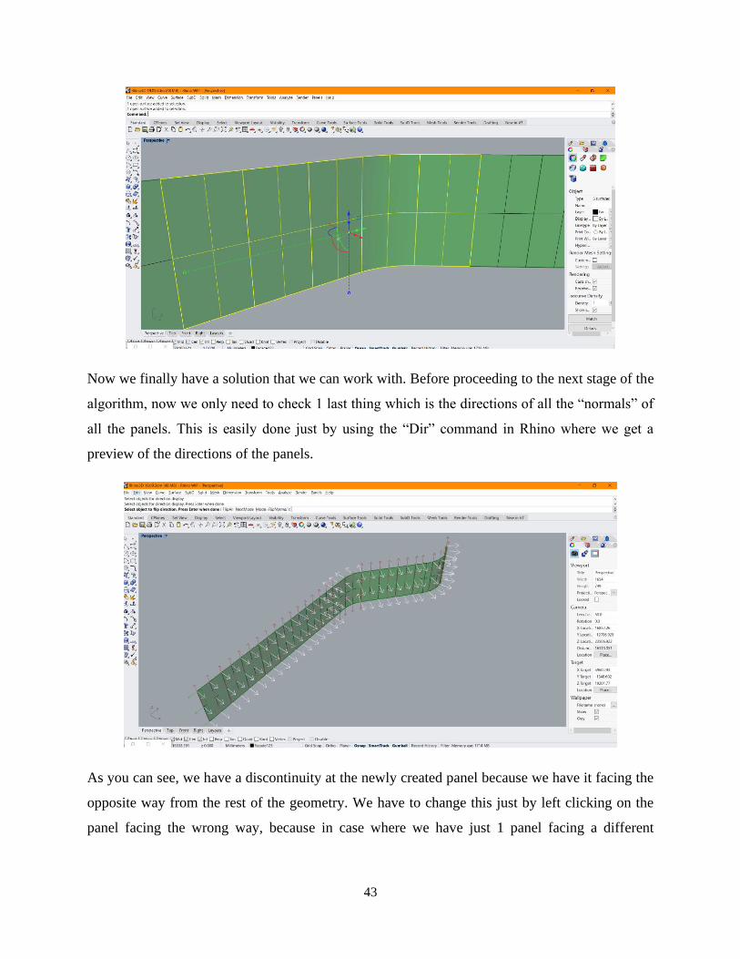
43
Now we finally have a solution that we can work with. Before proceeding to the next stage of the
algorithm, now we only need to check 1 last thing which is the directions of all the “normals” of
all the panels. This is easily done just by using the “Dir” command in Rhino where we get a
preview of the directions of the panels.
As you can see, we have a discontinuity at the newly created panel because we have it facing the
opposite way from the rest of the geometry. We have to change this just by left clicking on the
panel facing the wrong way, because in case where we have just 1 panel facing a different

44
direction – we will have an extrusion in the opposite way later in the process and the algorithm
will not be able to find a host for the elements.
The next step is to give the geometry to the result that we got from the extrusion of the curve.
The algorithmic shape of this step is presented in the figure below.
The surfaces now are divided with an additional UV grid network where each basic element is
being placed by using the Box Morph method that we previously experimented with. As we can
see we have an array of identical basic elements being hosted by the surfaces that we created.
The next step Is implementing the idea that we want these shapes to follow some specific rule on
how to change parametrically so we can manipulate them to get some specific result.
In our case we are planning to use this algorithm to create a façade system where, for example,
one of the functions will be to optimize the solar radiation which will be discussed later. For this
goal we give the algorithm an additional part where we can give the geometry this rule and
parameters on how they should change. The rule that the geometry needs to follow is that it will
be scaled depending on the distance of a given curve that is placed along the surfaces.

45
As we can see from the figure above, we are giving a simple curve between the elements and
along the surfaces. The idea is to change the dimensions of each of the elements (Diameter,
height, and width) depending on how close each and every element is to the curve. So, the closer
the element is to the curve it will be significantly smaller, and the further away is the element – it
will be bigger. The parameters defined in our case are that the elements will change in a range
from 0.3 to 0.7 of the original shape. We can see the result in the figure below.

46
Since this was a success and we managed to manipulate the geometry in a way that we want to,
the next step is to find a host for it, because in the original idea this geometry is planned to
actually represent the holes in the panels of the façade system. In this step only 1 problem
emerges, which is the displacement of the original surfaces by a value of the scale factor
previously used. In most cases this might present a real issue, but since we need to have a host
for the geometry this problem is very easily solved in our next step.
So now we need to create a solid from the surface that we previously managed to extract as an
extrusion from a curve. That is shown in the next step of the algorithm where we actualy use a
plug-in for Grasshopper called “Pufferfish” that helps us do this in a much simpler way. In order
for use to create a host domain for the geometry and solve the problem that we had in the
previous step – we use the “Offset surface” command twice as a chain. Basically with the first
usage we create an offset with the value of the scale parameter from before (also we are not
creating a solid with the first usage) and we are placing the geometry and the panels in the same
spot in our Rhino environment, and then we use the “Offset surface” command directly on the
first offset created – and this time we are making the algorithm to create our solid host with a
specific width, just enough so the geometry can pass through it as we can see on the figure
below.
Now, we can see that we have the scaled geometry as well as the solid panels created, and they
are well within their own boundaries.

47
In order for us to have the prepared geometry in a form of shapes in these panels, we simply need
to use the command “Trim solid” so we can create their difference.
We now have the final result of a system of panels that have parametric openings depending on
our future needs shown in the figure below.
At this point, where we successfully created our desired geometry with its parameters we have
proven that it follows the specific set of rules that we designed for it. Now we have an active
communication between Grasshopper and Rhinoceros3D, and we need to find a way how to
make this result communicate with a BIM environment.

48
5.1.3 Industry foundation classes – IFC
Before we continue on the phase where we establish the communication between these 3
softwares and environments, we need to address the real issue behind the need to have a data-
format which allows the exchange of information.
Thanks to BIM, it is possible to recreate a virtual building model which is not a simple 3D
representation, but a dynamic model that contains a range of information regarding: geometry,
materials, load-bearing structural members, costs, life cycle, etc. Design and construction of a
building involving various technical roles each operating within their area of competence. This
obviously leads to the strategic importance for the various participants to exchange information
in order to effectively collaborate in the realization and management of a shared project.
And this is the main reason why the need to exchange a multidisciplinary data model arises by
means of a standard file format, allowing a secure interoperability and interchange of data
without introducing errors and/or loss of information. This is the true purpose of having the IFC
data format. The IFC, Industry Foundation Classes, is a particular data format that has the
purpose to allow the inter-exchange of an information model without loss or distortion of data.
It is an open file format, neutral, not controlled by individual software houses and created to
facilitate interoperability between different operators. IFC is designed to process a building’s
data model throughout its entire life cycle, from feasibility up to its realization and maintenance,
passing through the various design and planning phases.
According to the “buildingSMART” consortium, IFC is the main tool used for Open BIM
implementation, “…a universal approach to the collaborative design, realization, and operation
of buildings based on open standards and workflows”.
The IFC architecture bases its structure on:
• Semantics
• Relations
• Properties
The elements are meant to describe the components of a building, such as plants, spaces, areas,
furniture, structural elements (columns, beams, walls, slabs, etc.), including the specific

49
properties of each object. Thanks to the division, each object can be associated with certain
properties, such as:
• Shape
• Cost
• Need for maintenance
• Position
• Energy performance
• Their connection with other elements
• Health and safety
• Mechanical and physical characteristics
All of this data is, in general, codified according to these three available formats:
• .ifc: default file format based on the ISO-STEP standard
• .ifcxml: encoding based on XML file structure
• .ifczip: a compressed archive of one of these previous formats also containing additional
material, such as PDFs or images
The main advantage offered by the IFC format is the ability to allow collaboration between the
various technical roles involved in the construction process, allowing them to exchange
information through a standard format.
This results in higher quality, the reduction of errors, reduction of costs and saving of time, with
consistent data and information flowing from the design phase through to realization and
maintenance.
50
5.1.4 Implementation of the algorithm in a BIM environment – Revit
In order for us to start implementing the result in a Revit environment, of course, firstly
we need the create the model of our building or at least the portion where we need to apply it. In
our case, since the idea is to use this geometry as a façade system - we create the Architectural
model with the specific plans and design so we have a very precise idea of how the geometry
will behave in Revit when we apply it. After the creation of the model, we now have a host for
the geometry. The simplest option is to try to “Bake” the geometry into Rhinoceros3D and then
export it as a specific file format.
• The first test was to export it as a “.3dm” file which is an open source file format which is
used for 3D graphics software. Developed by the openNURBS initiative, 3DM files are
inherently classified as computer-aided design (CAD) files as they can be processed by
several CAD applications. When we try to import the “.3dm” file into Revit we can only
import it with the Revit command “Create an In-Place Mass” which basically allows us to
place the predefined geometry at a specific location in the Revit environment, but the
issue with this option is that after we place it, we lose all the information from it and we
cannot define any properties for the imported geometry, which means that basically we
lose the main idea of a parametric geometry.
• The second test was to export the geometry as a family, and then import it in Revit as a
family. The revit family is defined as “A Family is a grouping of 2D and/or 3D
information that serves to represent a discrete building or documentation element in the
Project. It defines parametric, graphical, and documentation requirements.” With this
option, theoretically, we should be able to form the connection between the
environments, but it is nearly impossible to do so because of the complexity of the
geometry. With this option we need to create a new family for revit and place the already
prepared geometry, and for a new family we need to strictly define its dimensions and
values. When we have this kind of geometry with so many different elements with
different dimensions, it will take us a very long time.
• The third test was with a “.sat” extension, and what it does by definition is: The SAT file
extension stores three-dimensional geometry information within a standard text file
format. It is used to exchange 3D data between multiple systems and is saved in Spatial's

51
ACIS solid modeling format. This but when we try to do this – we get an error in Revit
which you can see in the figure below.
The error message “This family instance has too many edges. Remove unnecessary geometry or
split the instance into multiple instances” actually tells us that every single element that we
created in the Rhinoceros3D has multiple edges and because we have a fairly “complicated”
geometry – we cannot use this option. If we have a case of a simple geometry that needs to be
transferred into Revit – this might be the most preferable option to do so.
Since all these test have proven to be unsuccessful, we abandon the idea that we have to bake the
geometry first and find a way to export/import it, but instead find a way to have some preview
before baking so the geometry stays parametric until the very last moment.
The last test was done with Rhino.Inside. Rhino. Inside® is an open source Rhino WIP project
which allows Rhino and Grasshopper to run inside other 64-bit Windows applications such as
Revit, AutoCAD, etc. This is very exciting, because it allows us to open Rhinoceros3D as a plug-
in for Revit. And in that plug-in, we can directly open a Grasshopper file. The most valuable
outcome from this combination is that everything that we create via Grasshopper is presented
directly into the Rhino environment, and also we get a real-time preview directly into the Revit
environment as you can see in the figure below.

52
This opens up so many possibilities, few from which are the specific Tab in Grasshopper for
Revit with contains commands only for direct communication between Grasshopper and Revit.
One of the options that was used in this algorithm was the “Edge” command which directly
connects a specific edge in the Revit environment and gives the information to Grasshopper. In
this way we can directly work with Grasshopper into the Revit environment, which is what I did.
With this method now we no longer have issues with the placement of our geometry, the
translation between environments, the preservation of information. After getting a real-time
preview in Revit, everything we do is directly transferring information in that environment.
One of the issues that was discovered during the last stages of the thesis was the difficulty of
what Revit accepts as a “correct” geometry, which means that even if it takes more
computational power – we need to have as many control points as possible. As you can see in the
figure below, after baking the result in Rhinoceros3D we have a slight “cracking” of the
geometry which is actually an indicator of which panel will be damaged when given to Revit. In
the Rhinoceros3D environment the damage is not so significant and its possible to oversee this
during the baking.

53
However, when we finally bake the result in Revit, that is when the damage becomes much more
severe and noticeable. As you can see in the next figure the geometry is almost fully fractured or
shattered and it’s not solvable unless we re-create the surfaces (where the geometry is shattered)
at the starting phase and once again recreate the geometry step-by-step as we did before for all
the others, but with much finer detail, or in other words, as many more divisions and control
points grid.

54
The reason we are having this issue is a bit complicated. Revit is quite picky what it will accept
as a BREP. And its tolerance is only set to 1mm. I see that the Rhino file has a tolerance of:
Those are much tighter than Revit will handle. The procedure to fix this issue is as follows:
1. Using the attached Grasshopper script (figure below) to find the panels that failed. It
shows the failed results in magenta in Rhinoceros3D
2. I set to Tolerance Absolute to 0.001mm and Angle to 0.5.
3. Solid > Extract surface to extracted one face of the panels that were failing.
4. Used Rebuild on those faces with 10 control points in each direction. And we use the
Retrim option directly in Grasshopper.
5. Solid > Offset with FlipAll options to 5 mm thickness.
This is one of the challenges to the process, how to model clean enough so Revit will accept the
results.
Now we can even create an additional part of the algorithm that is focused on choosing the Revit
category, family, and type for the created geometry. You can see the script shown in the figure
below.

55
This part of the algorithm allows us to create a specific category in which the created geometry
will be placed from Grasshopper into Revit. First we only need to define a specific layer for the
geometry in Rhinoceros3D and then from the parameters included in the algorithm we choose
the category, and with that the algorithm creates a sub-category in Revit with the name that we
specified in the blank panels. Everything that changes in the algorithm is changed in the real-
time preview in Revit until we use the “Bake” command. However, this requires a lot of
computational power and the more complex the geometry or the bigger the changes –
significantly increases the computational time for the process. This allows us to directly bake
anything and everything we create in Grasshopper, through Rhinoceros3D – into Revit with
predefined parameters.
In the high-resolution rendered image below, you can see the final result for the geometry
attached to the architectural envelope as a façade system.

56
5.2 Simple roof solution using the same algorithm as a proof of concept for
the workability of the algorithm in all dimensions and directions
We have proven the concept of the algorithm that it works, but since we used it in a
façade system, we have basically shown that it can be applied in a vertical surfaces. In order to
give proof of concept that this algorithm works in any given direction onto any given surface, I
created a very basic concept of a roof for the building where using nothing but the algorithm I
created the geometry and the form. The algorithm for the roof is exactly the same as the one for
the facade system, but only applied on multiple horizontal surfaces and a set of inclined surfaces
by some angle. That is shown in the figure below.

57
In this phase, there was also 1 additional experiment performed, where I wanted to test if we can
create some elements to fill in the holes in the roof by using the same algorithm with an opposite
function. So, instead of using the elements to cut through the panels, I used the “Difference”
command between the panels and the elements, which gave me the result of the holes in the roof
as a solid element that can be placed in a specific category in Revit. For these elements just in a
testing phase I created them to be in the category “Mass” and have the properties of the
predefined material in Revit – “Glass”. The result is shown in the figure below.
5.3 Optimization of the openings of the façade system for a comfort shade
benefit evaluation regarding the analysis of the solar radiation
Another one of the possibilities this process gives us, is that we can take advantage of the
process and perform an optimization for a specific function of the building. In this case I chose to
perform an optimization of the openings of the façade system regarding the solar radiation
analysis throughout the 2 hottest months in Bologna. This analysis is performed by the plug-in
“Ladybug” for Grasshopper. It works on the basis of the coordinates of the building site which
we can give as an input from a simple “.epw” file.
For this process first we need to create the part of the algorithm that generates the sun path in a
specifically determined period of time in the year.

58
As we can see from the figure above, we have the building site coordinates as an input, and from
there we give that output to the location in the “Sun path” command, in which we also need to
put the period for which we want the analysis. As we can see, the result is the position of the sun
and its path to our building site in the period of July and August.
This information we need as an input in our next task, which is to find the total radiation.

59
As we can see, we find the total radiation depening on the orientation of our building. As we can
see there is nothing out of the ordinary since we have the highest amount of radiation focused on
the south part of the building.
The last step is to perform the optimization of the shading of the structure, which can be done in
a few simple steps with the algorithm.
Since the generation of this task requires an enormous amount of computational power, we had
to lower the accuracy of the result and get the analysis for the building in general. If we had the
computational power to perform this same analysis on a much more detailed profile with a very
high grid size, this could be done on each floor separately for each panel of the façade. From this
analysis we can see that we have a huge need of shades on the south-west side of the building,
whereas we basically need none on the north-east side. From this analysis now we can create the
curve along each floor so we can make the transformation of the geometry for the façade and
adjust the openings in the same in the most effective way.
60
6. Future application and possibilities
Rhino.Inside.Revit allows Rhino shapes and forms to be encoded into and categorized as
Revit elements. It is important to note that the easiest and quickest way of moving geometry into
Revit may not be the best method. Determining which the final goal of the forms in Revit can
improve the quality of the final Revit data structure and increase project efficiency. Revit data
model is based on a categorization system. Determining the best categories and subcategories to
use will allow the elements to be drawn and scheduled properly. The challenge is that not every
Revit category is available for each method discussed here.
There are 3 main ways to classify and move Rhino geometry to Revit. Each successive strategy
increases the integration within a BIM model, but each strategy also takes a bit more planning.
1. Using DirectShapes can be quite fast and takes the least amount of organizing. The
limited organization and speed make DirectShapes best for temporary drawing sets such
as competitions and early design presentations. DirectShapes may not the best for late
project phases.
DirectShapes are the most obvious and many times the easiest way to get Geometry from Rhino
into Revit. DirectShapes are generic Revit elements that can contain and categorize arbitrary
non-parametric geometry inside the Revit model. However, since the geometry is not parametric,
Revit does not know how they are created and cannot resolved interactions between
DirectShapes and other native elements. An example is that native Revit walls cannot be
extended to reach a DirectShape roof geometry. Good reasons for using DirectShapes include:
• Temporary models used in a competition or early design study submission for quick
drawings.
• Placeholders for part of the building that is still changing during design development.
• A completely bespoke component or assembly that cannot be modeled using Revit
native Families.

61
2. Developing Loadable Families with Subcategories works well for standalone elements in
a model or elements that might be ordered or built by an independent fabricator. Being
part of a Family, these objects could have their own set of drawings in addition to being
part of the larger project drawings.
Rhino objects imported as forms inside a Revit family allow for inserting multiple instances of
an object and also assigning subcategories. You can use subcategories to control the visibility
and graphics of portions of a family within a top-level category. Wrapping Rhino geometry
inside Loadable Families have many advantages:
• Repeated objects can be inserted multiple times allowing forms to be scheduled and
counted correctly
• Forms in loadable families can be edited by Revit if needed.
• Forms placed inside Family/Types can be placed in subcategories for further graphics
control and scheduling.
3. Use Rhino geometry to generate Native Revit elements is the best way to generate final
Revit elements. While it is not always possible to create everything with native elements,
native elements normally integrate best with the rest of the Revit team. These objects can
potentially be edited without any dependency on Rhino.Inside.Revit. While the creating
elements in this way can be limited, the resulting elements are native Revit elements.
Using built-in Revit System Families such as Walls, Floors, Ceilings, and Roofs can take the
most amount of thought, however, the extra effort can be worth it. Advantages of native elements
include:
• Great integration in the project BIM schema including maximum graphic control,
dynamic built-in parameter values and all access to all common project standard BIM
parameters as any native elements would have
• Elements can be edited even when Rhino.Inside.Revit is not available. The elements may
have dimensions attached to them. The elements may be used to host other elements
• Many Revit users downstream may not realize these elements were created with
Rhino.Inside.Revit
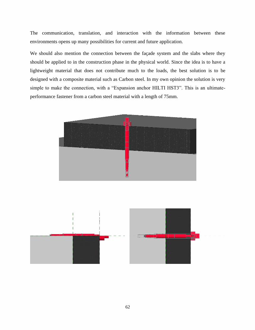
62
The communication, translation, and interaction with the information between these
environments opens up many possibilities for current and future application.
We should also mention the connection between the façade system and the slabs where they
should be applied to in the construction phase in the physical world. Since the idea is to have a
lightweight material that does not contribute much to the loads, the best solution is to be
designed with a composite material such as Carbon steel. In my own opinion the solution is very
simple to make the connection, with a “Expansion anchor HILTI HST3”. This is an ultimate-
performance fastener from a carbon steel material with a length of 75mm.

63
For the material properties of the façade system we discussed that at this stage is only considered
in the architectural design stage and we selected Carbon steel material from the algorithm. But
for future application there is a very exciting possibility because we can create a new material in
Revit, for example a composite material and simply select it from the list in Grasshopper after
we define the specific properties. With this approach and the fact that we already have the façade
system automatically divided in panels, we can consider having the full geometry for 3D
printing. This may not be very conventional, but considering that we have every panel different
from the next one and the complexity as a whole is at a very high level, the manufacturing of the
panels 1 by 1 is a very huge cost of time and money.
A different approach of the universal use of the algorithm is to be designed as a structural load
bearing system. So, instead of attaching the geometry to a host, we could simply change the
material and physical properties and consider it to be a structural member. The base of the
algorithm is most suited, for example, for an exo-skeleton of a stadium or a skyscraper, where
the exo-skeleton will be connected to the actual base skeleton of the structure. In this case the
geometry will have to have its physical properties predefined so it can be load bearing. With this
approach we have another possibility of the future use if we consider adding a Grasshopper
compatible software for the analysis, like Karamba3D or Milipede. After we design the exo-
skeleton we can simply perform structural analysis in this system and have the deformations,
deflections and so on.

64
Thinking “out-of-the-box”, the algorithm can be
adapted for energy optimization and
conservation. Since we had a preview of how
we created the “fillings” for the holes in the
roof, these elements can be, in the future, solar
or voltaic panels that actually generate energy.
The shape and the dimensions are very
interactive and because of the parameters we set
in the algorithm we can change them to a
compatible form so we can place the panels in.
With this approach we are basically considering
the sustainability of the structure. This idea is
already created by BURKETTDESIGN,
Denver, Colo., United States and is called
“Science Pyramid”. The photovoltaics are by
Onyx Solar. Science Pyramid is an interactive
learning center located in the Denver Botanic
Gardens. The façade, inspired by natural forms, appears fractured, like shifting tectonic plates.
The building’s 16 faceted sides are uniformly clad in fiber-cement panels, manufactured by
SwissPearl, in a pattern modeled after the structure of beehives. Interspersed among these panels
are custom hexagon-shaped skylights which glow amber when backlit, completing the
honeycomb effect. The angle of the façades increased the amount of surface area exposed to
direct sunlight. To compensate for this, the architects fit the skylights with special
electrochromic glass, which automatically adjusts opacity depending on the strength of the sun.
They also used this as an opportunity to integrate photovoltaic panels into the building envelope.
These hexagonal solar modules, fabricated for the project by Onyx Solar, were custom-specified
to blend in with the fiber-cement cladding. As Barton Harris of Burkett Design explained: “to
completely integrate the photovoltaic modules in the aesthetics of the façade, not only was the
color of the glass carefully chosen to match the color of the surrounding modules but its surface
was coated with a similar sheen.”

65
Furthermore, another use for the algorithm is that we can use it to reduce the overall waste and
carbon footprint of the towers. Lets consider “Bosco Verticale” which is a pair of residential
towers in the Porta Nuova district of Milan, Italy, between Via Gaetano de Castillia and Via
Federico Confalonieri near Milano Porta Garibaldi railway station. They have a height of 111
metres (364 ft) and 76 metres (249 ft) and contain more than 900 trees (approximately 550 and
350 in the first and second towers, respectively) on 8,900 square metres (96,000 sq ft) of
terraces. Within the complex is an 11-storey office building; its facade does not include plants.
In our case we can divide the panels to, for example, in 2 groups: “Active” and “Inactive” and
create a separate lists in the algorithm placing them in their own groups. Let us consider that the
active are the panels that are contributing to the shade optimization and the inactive panels are
the panels that are not contributing to the optimization. We can use the list of inactive panels to
make an additional extrusion to make them more reliable as hosts to the plants with which we
can contribute to push the building a step closer to be environmentally responsible and resource-
efficient throughout a building's life-cycle.

66
7. Conclusion
At the beginning the idea we had a very simple idea to find a way to transform the most basic
geometric element into a responsive combination of the same has brought us to the point where
we managed to collide two “worlds” interacting with each other and are able to exchange a lot of
complex information from the first to the other and vice versa.
We discussed at length about the advantages and possibilities of BIM as a process but for the
creation of the thesis and its future application “openBIM” comes to mind. When we think and
discuss the future application we have to, in a way, “expand” the possibilities of the process and
algorithm that we created and consider them to be “openBIM” compliant.
“openBIM” extends the benefits of BIM (Building Information Modeling) by improving the
accessibility, usability, management, and sustainability of digital data in the built asset industry.
At its core, openBIM is a collaborative process that is vendor neutral. openBIM processes can be
defined as sharable project information that supports seamless collaboration for all project
participants. openBIM facilitates interoperability to benefit projects and assets throughout their
lifecycle. By breaking down data silos, openBIM® can greatly improve project delivery and
asset performance. Firms that adopt an openBIM® approach develop cross-party collaboration,
enhanced communication, and industry standard exchange methodologies. This delivers better
project outcomes, greater predictability, improved performance, and increased safety with
reduced risk. Throughout the whole lifecycle of an asset, openBIM helps connect people,
processes, and data to achieve asset delivery, operation, and maintenance goals. “openBIM”
removes the traditional problem of BIM data that is typically constrained by proprietary vendor
data formats, by discipline or by the phase of a project. By adhering to international standards
and working procedures, openBIM® extends the breadth and depth of the use of BIM by
creating common alignment and language. Technical applications developed for openBIM®
improve the management of data and eliminate disconnected workflows. Independent quality
benchmarks ensure reliable open data exchanges.
“openBIM” permits digital workflows based on vendor-neutral formats such as IFC, BCF,
COBie, CityGML, gbXML, etc...

67
“openBIM” enables an accessible digital twin which provides the core foundation to a long-term
data strategy for built assets. This provides better sustainability for projects and for more
efficient management of the built environment. The principles of openBIM recognize that:
• Interoperability is key to the digital transformation in the built asset industry
• Open and neutral standards should be developed to facilitate interoperability
• Reliable data exchanges depend on independent quality benchmarks
• Collaboration workflows should not be limited by proprietary processes or data formats
• Flexibility of choice of technology creates more value to all stakeholders
• Sustainability is safeguarded by long-term interoperable data standards
The benefits for the built asset industry are that:
• openBIM greatly enhances collaboration for project delivery
• openBIM enables better asset management.
• openBIM provides access to BIM data created during design for the whole life cycle of
the built asset.
• openBIM extends the breadth and depth of BIM deliverables by creating common
alignment and language by adhering to international standards and commonly defined
work processes.
• openBIM facilitates a common data environment that provides opportunities for users to
develop new workflows, software applications and technology automation.
• openBIM enables an accessible digital twin which provides the core foundation to a long-
term data strategy for built assets
Starting from the most basic geometry – a cube, we defined its parameters and we transformed it
into an interactive element that is able to change all of its dimensions and therefore dictate the
shape and patterns for the final result. This element served as a base for the algorithm which was
instructed to give that element a rule, or a law to follow which begins the transformation of the
very same. This law requires only a surface with a specifically defined “UV” divisions into
which it will project the element and then create the pattern. This pattern of elements bonded
together is later transformed yet again, with a different set of rules which consider the pattern of

68
elements as a whole and manipulates it according to the previously given law. The resulting
array of elements at this point needs a host which is able to adopt the new set of generated
elements and for this we introduce the same surfaces that we used before. Since the location of
the geometry and the host are at the very same coordinates, we can easily create the difference
between the two from which we get the result. This opens up the possibility for us to basically
work and have a real-time preview of the result directly into a BIM environment (Revit) with
geometry that is created by an algorithm into a visual programming language and environment
(Grasshopper) that dictates the transformations and manipulations which runs within the
Rhinoceros3D computer-aided design (CAD) application in a form of a façade.
With this we have proven that we can actually take the most basic geometric element, project it
onto the most basic rectangle surface from the most basic curve or a polyline and implement a
set of rules that makes these 3 simple elements into a very complex, responsive, parametric
design with many more future applications and possibilities.
We basically created a combination between the second option “Developing Loadable Families
with Subcategories” and third option “Using built-in Revit System Families such as Walls,
Floors, Ceilings, and Roofs” for the Revit-Rhinoceross3D connection. Our geometry is being
placed in a subcategory of a previously defined category by us in the process which is the
category of “Generic Models”. This subcategory can adopt any material properties that Revit
possesses, or we can even create completely new properties depending on our needs for that
subcategory in Revit.
We have experimented with the methods and various approaches on how to make them
compatible and eligible for the transfer of information and we learned many of the issues that can
arise and how to solve most of the issues along the process. Along the way, we also shown that
the algorithm is not only valid for regular vertical surfaces with simple shape, but also for any
surface that is facing any direction in the 3D environment through the rough creation of the roof.
Furthermore, we have proven that the algorithm can be used for optimization such as shade
optimization, as well as the possibility of its architectural and structural future uses. The
possibilities are basically endless, and the application span is very large since we have a simple
geometry that can transform in so many ways and adopt material and physical properties in any
way that we define them.

69
As a conclusion, in my opinion, we can safely say that from a lot of aspects with this method we
gain a big advantage over the traditional method for the design stage. The CAD environment in
Rhinoceros3D gives us much “freedom” for designing the geometry and considering that we
have the real-time preview in a BIM environment is a very desirable option. Initially we have a
starting advantage in a BIM environment because we have most of the elements and components
to be interactive and have their parameters changeable, but with this methodology we also have
the tools to build a very complex and specific geometry which can adopt the properties of any
built-in material of Revit, either the physical or graphical and the geometry can be kept “open” in
the sense that with the preview we can manipulate it until we have the wanted result ready. This
means that we can work on our elements or components in a CAD environment while not being
obliged to place any components in the BIM environment while at the same time having a
preview of everything we created. Firstly this means that any change we make in the
Grasshopper and/or Rhinoceros3D environment is directly changed in the preview of the BIM
environment with which we save a huge amount of time for the design stage and furthermore the
required computational power is significantly lower which gives us a computational time
difference as well.
The final result of the architectural envelope and the geometry created by the algorithm attached
to can be seen in the high-resolution Revit renderings below.

70
71
8. Bibliography
• Barriers of Implementing BIM in Construction Industry from the Designers’ Perspective:
A Hong Kong Experience (Caroline T. W. Chan 1+ 1 Department of Building, Science
and Technology, City University of Hong Kong)
• Building Information Modeling (BIM): A New Paradigm for Visual Interactive Modeling
and Simulation for Construction Projects (Salman Azhar McWhorter School of Building
Science, Auburn University, Auburn, Alabama, USA [email protected] Abid
Nadeem Hong Kong College of Technology International, Kowloon, Hong Kong Johnny
Y. N. Mok Hong Kong College of Technology International, Kowloon, Hong Kong Brian
H. Y. Leung Hong Kong College of Technology International, Kowloon, Hong Kong)
• Kreider, Ralph G. and Messner, John I. (2013). “The Uses of BIM: Classifying and
Selecting BIM Uses”. Version 0.9, September, The Pennsylvania State University,
University Park, PA, USA. http://bim.psu.edu.
• Engineering in a computational design environment – New Terminal 3 at Shenzhen
Bao’an International Airport, China - Thorsten Helbig, Florian Scheible, Florian Kamp,
Roman Schieber
• Generative Algorithms using Grasshopper by Zubin Khabazi (2012)
• http://www.amblav.it/news/norme+uni+11337-1,+uni+11337-4+e+uni+11337-
5,+gestione+digitale+dei+processi+informativi+delle+costruzioni_14359.aspx
• https://www.archdaily.com/302490/a-brief-history-of-bim
• https://www.thenbs.com/knowledge/what-is-the-pas-1192-framework
• https://www.ingenio-web.it/9176-aia---american-institute-of-architectures-pubblica-una-
guida-al-bim
• https://www.uni.com
• https://www.united-bim.com/bim-execution-plan-bep-guide-for-successful-bep-design-
and-execution/

72
• https://www.bim.psu.edu/bim_uses/
• www.autodesk.com
• www.bimmodel.co
• www.engineering.com
• https://medium.com/generative-design/learning-from-nature-fe5b7290e3de
• https://en.wikipedia.org/wiki/Generative_design
• https://biblus.accasoftware.com
• https://www.buildingsmart.org/about/openbim/openbim-definition/
• https://theconstructor.org/building/types-site-selection-residential-building
• www.rhino3d.com