generator control system used in aircraft power supply · 2) ac main generator: the main ac...
TRANSCRIPT

International Journal of Scientific and Research Publications, Volume 8, Issue 8, August 2018 516 ISSN 2250-3153
http://dx.doi.org/10.29322/IJSRP.8.8.2018.p8065 www.ijsrp.org
Generator Control System Used in Aircraft Power Supply
Thin Thiri Win
Department of Electrical Systems and Instrumentation, Myanmar Aerospace Engineering University, Meiktila Township, Mandalay Division, Myanmar
DOI: 10.29322/IJSRP.8.7.2018.p8065 http://dx.doi.org/10.29322/IJSRP.8.8.2018.p8065
Abstract- Aircraft have two primary sources of electrical
energy. The first is the generator, which converts mechanical energy to electrical energy. The second is the battery, which converts chemical energy to electrical energy. The generator is the main source and the battery is the auxiliary source. In aircraft, the electrical system is primarily an AC system. Aircraft electrical components operate on many different voltages both AC and DC. However, most of the systems are 115 VAC with 400 Hz, 28 VDC and 26 VAC is also used in aircraft for lighting. DC is also supplied from a battery installation. The battery provides 28 VDC. The function of the electrical system is to generate, regulate and distribute electrical power throughout the aircraft. New generation aircraft rely heavily on electrical power because of the wide use of electronic flight instrument systems. For aircraft constant frequency systems 400 Hz has been adopted as the standard. The application of 400 Hz frequency, which is higher than usual frequencies, offer several advantages over 60 Hz - notably in allowing smaller, lighter power supplies to be used for aircraft operations and computer applications. Index Terms- Power Generation System, Power Generation Control, Integrated Drive Generator, Constant Speed Drive, Generator Control Unitt
I. INTRODUCTION AS the aircraft fly higher, faster and grow larger the service
that the aircraft electrical power system has to satisfy also grow more and more complex. There are several different power sources on aircraft to power the aircraft electrical systems. These power sources include: engine driven AC generators, auxiliary power units (APU), external power and ram air turbine (RAT). The primary function of an aircraft electrical system is to generate, regulate and distribute electrical power throughout the aircraft.
The electrical power generation system supplies all the electrical consumers with enough electrical power on the aircraft. There are two main types of power in power generation, the first one is Direct Current (DC) power and the other one is Alternating Current (AC). The main advantage of AC power is that it operates at a higher voltage; 115 VAC rather than 28 VDC for the DC system. The use of the higher voltage is not an advantage in itself; in fact higher voltage is most apparent. For a given amount of power transmission, a higher voltage relates to an equivalent lower current. The lower the current, the lower the losses such as voltage drops (proportional to current) and power
losses (proportional to current squared). Also as current conductors are generally heavy it can be seen that the reduction in current also saves weight; a very important consideration for aircraft systems.
II. COMPONENTS OF GENERATOR CONTROL SYSTEM USED IN
AIRCRAFT The A320 family includes Airbus A318, A319, A320 and
A321. The family has integrated state-of-the-art technology in its overall operation, including: fly-by-wire flight control, side-stick controller, and digital avionics to support these functions.
A. Integrated Drive Generator (IDG) The integrated drive generator (IDG) consists of a Constant
Speed Drive (CSD) and AC generator mounted side by side in a single housing. The CSD performs the operation by controlled differential action to maintain the constant output speed required to drive the generator.
The input constant speed of the generator provides the constant voltage and constant frequency generator output. The output of the generator used in A320 is 115VAC, three-phase, 400 Hz. The Flight Authority Digital Engine Control (FADEC) provides the GUC with the corresponding engine speed information, which is also used for the under speed protections. The drive speed varies according to the engine rating. The IDG internal gearing, converts the variable gearbox frequency to a stable 400Hz. The IDG supplies a 115 VAC, three-phase, and 400 Hz AC.
Fig.1 Internal Connection IDG

International Journal of Scientific and Research Publications, Volume 8, Issue 8, August 2018 517 ISSN 2250-3153
http://dx.doi.org/10.29322/IJSRP.8.8.2018.p8065 www.ijsrp.org
1) Constant speed drive: The CSD converts the variable input
speed (4900 to 9120) provided by the engine gearbox to the constant speed (12000 rpm) through the CSD hydro mechanical components. A mechanical governor, acting on a hydraulic trim unit, controls the differential-gear in order to maintain the constant output speed. A mechanical epicyclic differential-gear transmits power to the generator of the IDG.
2) AC main generator: The main AC generator consists of a 2 pole rotor and a three-phase winding stator. As the rotor rotates, the DC field induces an AC voltage in the stator windings. The AC generator portion of the Integrated Drive Generator (IDG) is a three-phase, brushless, spray oil-cooled unit. The output constant speed is regulated at 12000 rpm. The generator rotor consists of an exciter rotor, and a 4 pole main field rotor. The exciter rotor and main field rotor are mounted on a common shaft supported by a roller bearing set at the drive end and a ball bearing set at the opposite end. The generator is a three-stage assembly which has three machines connected in cascade. The first machine (Pilot Exciter (PE)) is a 12 pole Permanent Magnet Generator (PMG). The Permanent Magnet Generator (PMG) rotor is mounted on the output ring gear of the differential assembly. The main generator stator, exciter stator, PMG stator and generator Current Transformer (CT) are mounted in the housing. Rotating diodes rectify the three-phase output of the main exciter rotor. The resulting DC current feeds the third machine (main alternator) rotor winding. Thus, the main alternator receives excitation for the rotating salient 4 pole field from the rectified output of the main exciter. The main alternator has a three-phase star-connected stator winding. The three phases star point neutral are taken to the generator output terminal block.
B. Generator Control Unit (GCU) The GCU is supplied by the Permanent Magnet Generator
(PMG). The GCU is also supplied by the AC network. The GCU has four different functions. They are; 1) Voltage regulation 2) Control , protection of the network and the generator 3) Control of the various indications 4) System test and self-monitoring
The main functions of the GCU are: 1) Regulation of the generator voltage 2) Regulation of the generator frequency 3) Regulation of the generator speed (Servo Valve (SV)
control) 4) Control and protection of the network and the generator 5) Interface with System Data Acquisition Concentrator
(SDACs) for the ECAM 6) Interface with Full Authority Digital Engine Control
(FADEC) for engine speed 7) Interface with Centralized Fault Display System (CFDS) via
the Ground and Auxiliary Power Control Unit (GAPCU)
Fig. 2 Generator control unit (GCU)
C. APU Generator The AC auxiliary generation comes from the APU generator.
This generator can: 1) In flight, replace either or both engine generator(s) in case of
failure. 2) On the ground, supply the aircraft electrical network when
the electrical ground power unit is not available. The APU generator is not interchangeable with the
Integrated Drive Generators (IDGs). It is driven at a constant speed by the APU and can be connected to the electrical network in flight in case of any generator failure. It can supply the entire electrical network if no other power sources are available. The APU directly drives the APU generator at a nominal 24000 rpm constant speed. The APU gearbox supplies the oil for cooling and lubrication of the generator. The cooling circuit is common to the APU and the generator. The APU supplies, scavenges, drains the oil. The generator is a brushless oil-cooled generator with a nominal 115/200 V, 90 kVA, three-phase, 400 Hz output. The generator includes three stages which are: 1) Pilot exciter 2) Main exciter 3) Main alternator
The operation principle is the same as that of the IDG generator. The operation of the APU generator is through the APU generator pushbutton switch, which has two stable positions:(1) when in OFF position, the pushbutton switch is released, and the white OFF legend is on. The generator is shut down (de-energized) and the line contactor is opened and (2) when the pushbutton switch is pushed, the generator is energized, because its rotational speed is high enough. If the electrical parameters are correct, the GCU controls the line contactor closing: this causes the supply of the transfer circuit. The APU GLC supplies the aircraft electrical network if the other power sources are not available.

International Journal of Scientific and Research Publications, Volume 8, Issue 8, August 2018 518 ISSN 2250-3153
http://dx.doi.org/10.29322/IJSRP.8.8.2018.p8065 www.ijsrp.org
D. AC Emergency Generator
The AC emergency generation comes from the AC emergency generator. This generator is used when; 1) Loss of the two main generation sources and 2) unavailability of the auxiliary generation.
The emergency generation system is mainly composed of a Constant Speed Motor/Generator (CSM/G) including a hydraulic motor and drives a generator, and a Generator Control Unit (GCU). The hydraulic motor speed is regulated by a servo valve. The generator operation principle is identical to that of the main or auxiliary generation. During transient configuration, battery 2 and then the Permanent Magnet Generator (PMG) supplies the CSM/G control unit and the exciter field through a voltage regulation module.
The voltage regulation module maintains the Point Of Regulation (POR) at a nominal voltage value (115 VAC). The generator output characteristics are: three-phase 115/200 VAC, 400 Hz (12000rpm), output power: 5 kVA continuously. As the emergency AC generator parameters are correct, the emergency Generator Line Contactor (GLC) is supplied by the CSM/G control unit. The emergency AC generator has priority to supply the AC and DC essential buses.
III. GENERATOR CONTROL SYSTEM USED IN AIRBUS A320 FAMILY
The A320 family includes Airbus A318, A319, A320, A321. The family has integrated state-of-the-art technology in its overall operation, including: fly-by-wire flight control, side-stick controller, and digital avionics to support these functions
A. Normal Operation Condition of A320 Family In normal configuration, both BTCs are de-energized. IDG 1
generator supplies AC BUS 1 and IDG 2 generator supplies AC BUS 2. In normal flight configuration, each generator supplies its own distribution network via its Generator Line Contactor (GLC). The two generators are never electrically coupled.
Fig.3. Normal operation of AC generation
The Constant Speed Drive (CSD), in the IDG, drives the AC generator at constant speed. Each generator is controlled, via a GCU, by a GEN pushbutton switch located on the electrical (ELEC) panel on the overhead panel. The order of distribution priorities are: 1) On side IDG to own bus, the IDG 1 to AC BUS 1 and the
IDG 2 to AC BUS 2 2) External power 3) APU generator 4) Opposite IDG: IDG 1 to AC BUS 2 or IDG 2 to AC BUS 1
B. Abnormal Operation Condition of A320 Family
The generator 1 (IDG 1) failure, generator 2 (IDG 2) can supply the AC BUS 1 and 2.The following control or fault signals cause generator shutdown or de-energization; 1) IDG disconnection 2) GLC failure (BTC is only locked out) 3) Engine shutdown with the ENG 1(2) FIRE pushbutton
switch 4) PMG short circuit 5) Over/under voltage 6) Over/under frequency 7) Open cable (IDG position)
Fig. 4 Abnormal operation of AC generation The following conditions are also turned off the generator. They are: 1) If over-voltage of IDG and APU generator is about of
highest of Point Of Regulation (POR) 130 VAC (+ or -) 1.5 V, the generator logic contactor (GLC) and generator control relay (GCR) turn off the voltage regulator (during 4 to 5 sec),
2) If under-voltage of IDG and APU generator is about of lowest phase of Point Of Regulation (POR) 100 VAC (+ or -) 4 V, the generator logic contactor (GLC) turn off the

International Journal of Scientific and Research Publications, Volume 8, Issue 8, August 2018 519 ISSN 2250-3153
http://dx.doi.org/10.29322/IJSRP.8.8.2018.p8065 www.ijsrp.org
voltage regulator (during 4 to 5 sec), 3) If over-frequency of IDG and APU generator, sensing from
PMG frequency, is about of 433 Hz (+ or -) 3 Hz, trip from the generator logic contactor (GLC) and generator control relay (GCR), turn off the voltage regulator (during 3 to 5 sec),
4) If under-frequency of IDG and APU generator, sensing from PMG frequency, is about of 363 Hz (+ or -) 3 Hz, trip the generator logic contactor (GLC) and generator control relay (GCR), turn off the voltage regulator (during 3 to 5 sec).
C. AC Main Generation Operation Control When the input speed is about 12,000 rpm, the PMG
mounted on the same shaft of the aircraft engine is energized. Then PMG supplied the excitation field through the Generator Control Relay (GCR). If the electrical parameters are correct, the operation of GCR is controlled by the control and regulation of Generator Control Unit (GCU). The excitation current depends on the comparison between the voltage sensed at the Point Of Regulation (POR) and a reference voltage. If the electrical parameters are correct, the Generator Line Contactor (GLC) closes.
The GCUs use the CT outputs for protection functions (differential current, over current, overload). One CT is located inside the IDG and the other is just before the GLC. The excitation control and regulation module keeps the voltage at the nominal value (115 VAC) at the Point Of Regulation (POR). Then the voltage at the POR is compared to 115 VAC (reference) and used as an operational error to regulate the field current. The GCU supply from the aircraft network is duplicated (back up supply). The supply is taken from the DC essential system. The excitation control and regulation module keeps the voltage at the nominal value at the Point Of Regulation (POR).
Fig.5. AC Main Generation Operation Control
The generator is controlled by the corresponding generator pushbutton (P/B) switch. When pressed in, if the generator speed
is high enough, the generator is energized. If the delivered parameters are correct, thus the Power Ready Relay (PRR) closed; the Generator Line Contactor (GLC) closes to supply its network. When the GEN P/B is released out after fault detection, the GCU is reset. The GCR and the PRR are reset.
D. Voltage Regulation The voltage regulation is achieved by regulating the
generator excitation current. It also supplies the exciter field through the Generator Control Relay (GCR), which is normally closed, and through a rectifier. When the generator starts running, the PMG supplies the GCU. The exciter field current is reduced inside the GCU until 335 Hz is obtained. As the PMG frequency is below the threshold, the generator excitation is reduced through the excitation control module. The voltage regulation shutdown signal, generated by the protection module, triggers the voltage regulation shutdown control module which simulates a high generator load signal via the current limit module. As soon as the PMG frequency is over the threshold, the generator excitation is regulated normally. The excitation current depends on the comparison between the voltage sensed at the Point Of Regulation (POR) and a reference voltage. As the parameters are correct, the Generator Line Contactor (GLC) closes. The generator excitation also depends on the load. If a fault is detected by the GCU protection module, the voltage regulation shutdown control module simulates a high generator load signal. The exciter field coils are no longer supplied. The GCR and GLC are tripped.
Fig.6. Voltage regulation
E. AC Auxiliary Generation Operation Control When two main generators are out of operation, the APU
generator comes in operation. Speed regulation function of IDG and APU generator are different. Allows the APU to run 15 minutes.
International Journal of Scientific and Research Publications, Volume 8, Issue 8, August 2018 520 ISSN 2250-3153
http://dx.doi.org/10.29322/IJSRP.8.8.2018.p8065 www.ijsrp.org
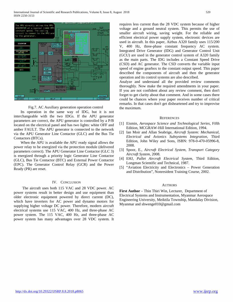
Fig.7. AC Auxiliary generation operation control Its operation in the same way of IDG, but it is not
interchangeable with the two IDGs. If the APU generator parameters are correct, the APU generator is controlled by a P/B located on the electrical panel and has two lights: white OFF and amber FAULT. The APU generator is connected to the network via the APU Generator Line Contactor (GLC) and the Bus Tie Contactors (BTCs).
When the APU is available the APU ready signal allows the power relay to be energized via the protection module (delivered parameters correct). The APU Generator Line Contactor (GLC 3) is energized through a priority logic Generator Line Contactor (GLC), Bus Tie Contactor (BTC) and External Power Contactor (EPC). The Generator Control Relay (GCR) and the Power Ready (PR) are reset.
IV. CONCLUSION The aircraft uses both 115 VAC and 28 VDC power. AC
power systems result in better design and use equipment than older electronic equipment powered by direct current (DC), which have inverters for AC power and dynamo motors for supplying higher voltage DC power. Therefore, modern aircraft electrical systems use 115 VAC, 400 Hz, and three-phase AC power system. The 115 VAC, 400 Hz, and three-phase AC power system has many advantages over 28 VDC system. It
requires less current than the 28 VDC system because of higher voltage and a ground neutral system. This permits the use of smaller aircraft wiring, saving weight. For the reliable and efficient electrical power supply system, electronic devices are used in aircraft. In this paper, Airbus A320 family uses 115/200 V, 400 Hz, three-phase constant frequency AC system. Integrated Drive Generator (IDG) and Generator Control Unit (GCU) are used in the generator control system of A320 family as the main parts. The IDG includes a Constant Speed Drive (CSD) and AC generator. The CSD converts the variable input speed of engine gearbox to the constant output speed. This paper described the components of aircraft and then the generator operation and its control systems are also described. Analyze and understand all the provided review comments thoroughly. Now make the required amendments in your paper. If you are not confident about any review comment, then don't forget to get clarity about that comment. And in some cases there could be chances where your paper receives number of critical remarks. In that cases don't get disheartened and try to improvise the maximum.
REFERENCES
[1] Eismin, Aerospace Science and Technological Series, Fifth Edition, MCGRAW-Hill International Edition, 1994.
[2] Ian Moir and Allan Seabrige, Aircraft System: Mechanical, Electrical and Avionics Subsystems Integration, Third Edition, John Wiley and Sons, ISBN: 978-0-470-05996-8, 2008.
[3] Spoor, E., Aircraft Electrical System, Transport Category Aircraft System, 2008.
[4] EHJ, Pallet Aircraft Electrical System, Third Edition, Longman Scientific and Technical, 1987.
[5] “Aviation Electricity and Electronics – Power Generation and Distribution”, Nonresident Training Course, 2002.
AUTHORS First Author – Thin Thiri Win, Lecturer, Department of Electrical Systems and Instrumentation, Myanmar Aerospace Engineering University, Meiktila Township, Mandalay Division, Myanmar and [email protected]